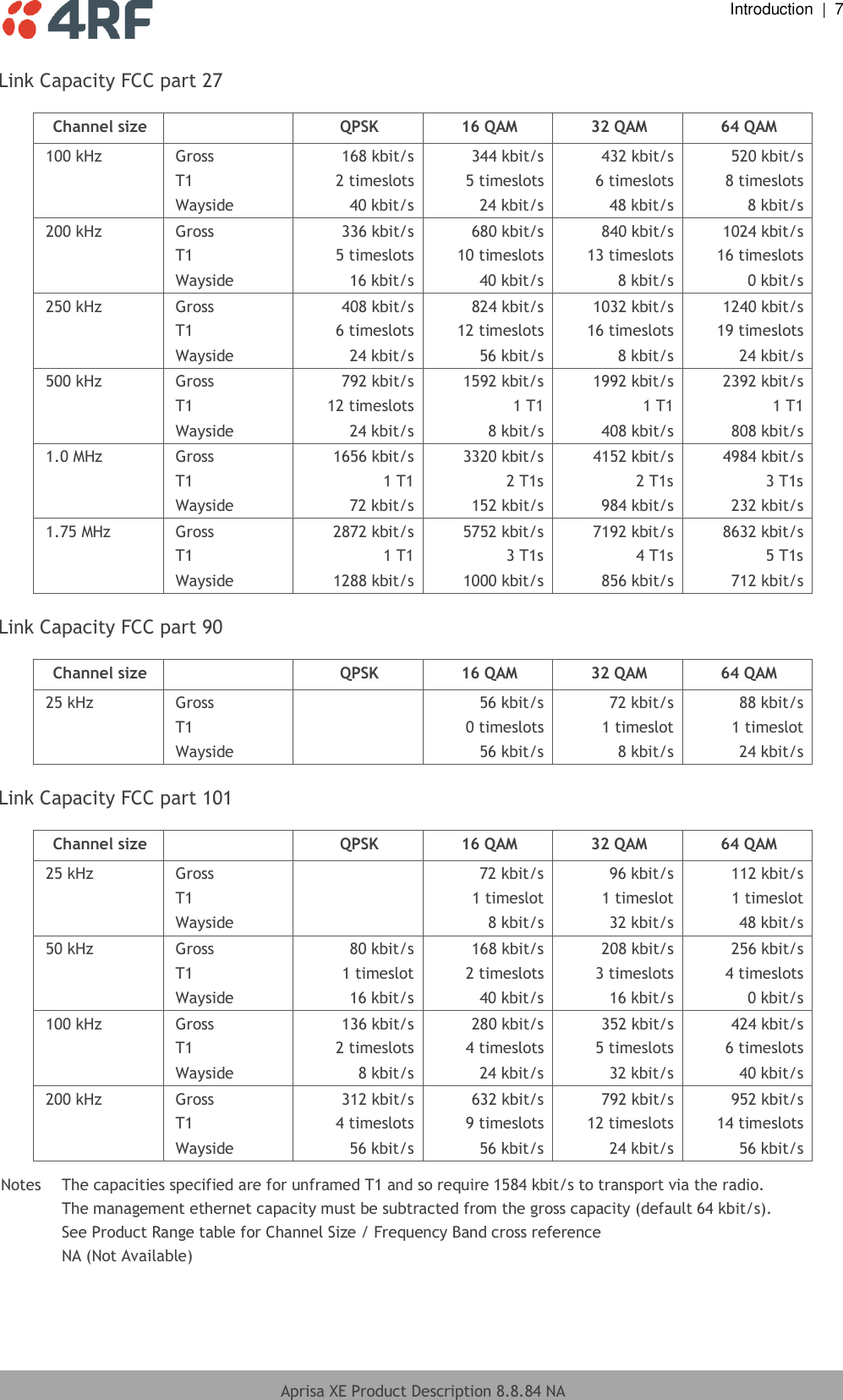
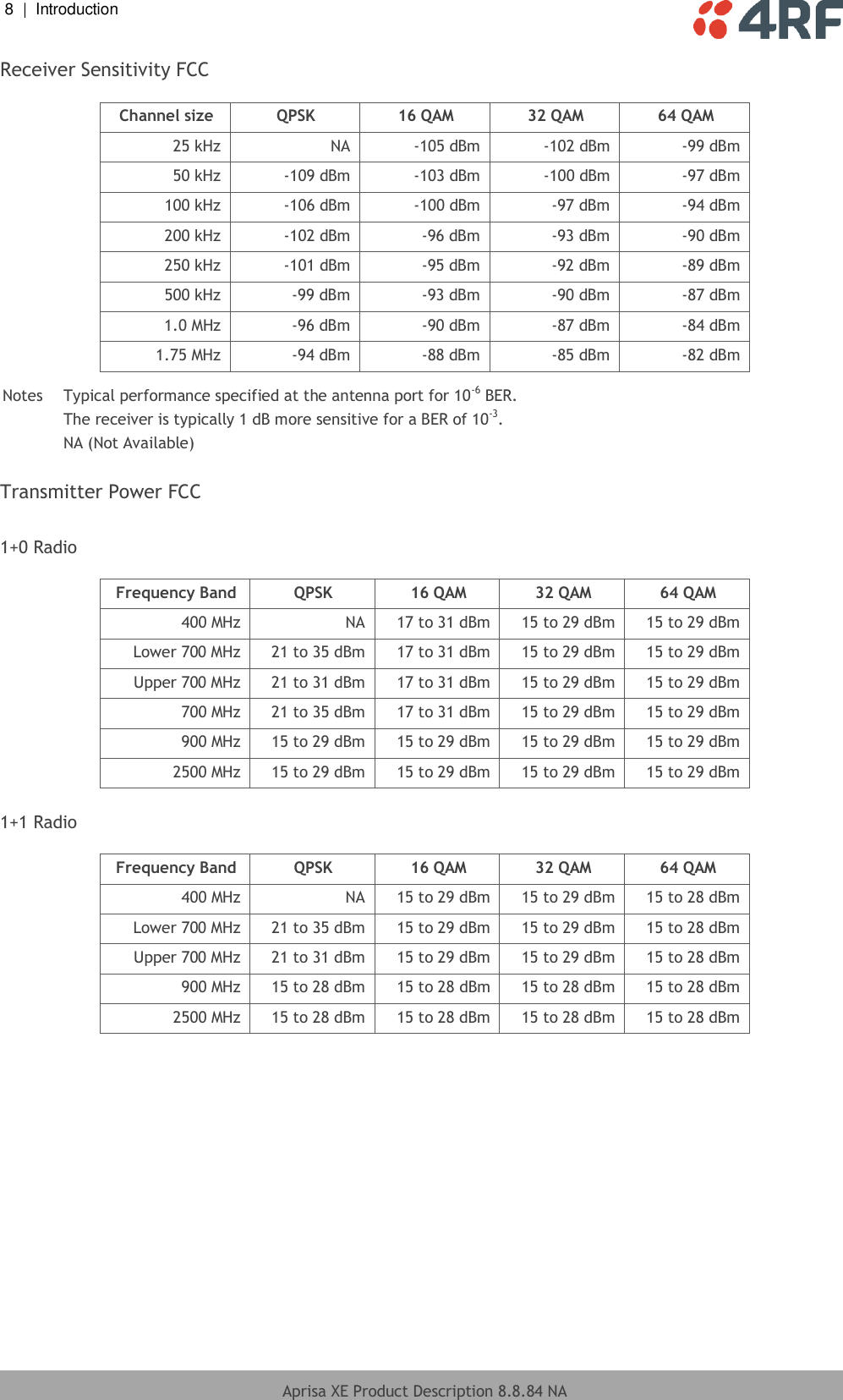
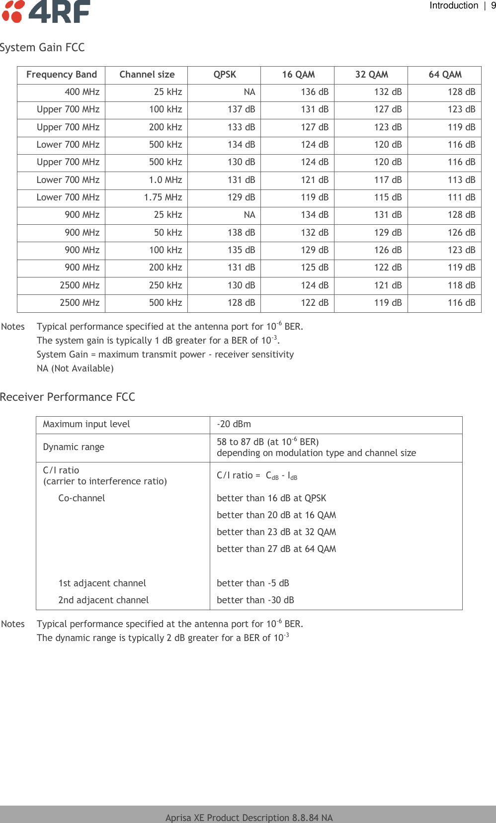
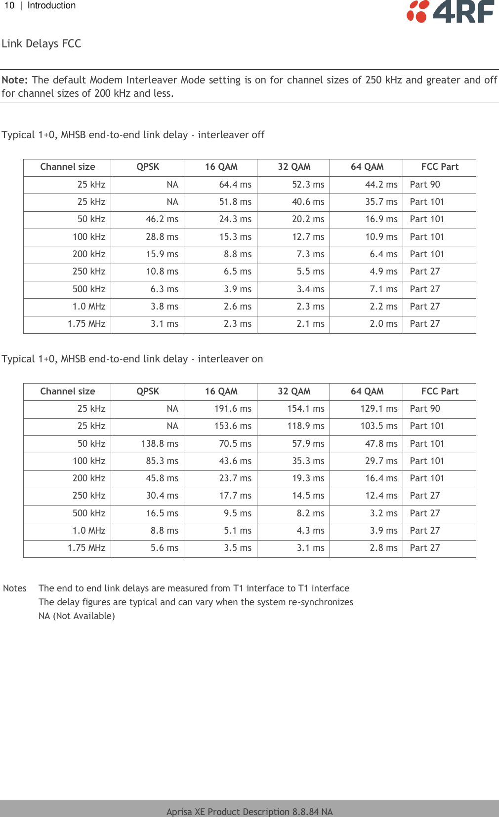
4RF XE757M170 Digital Transceiver User Manual Aprisa XE Product Description 8 8 84 NA

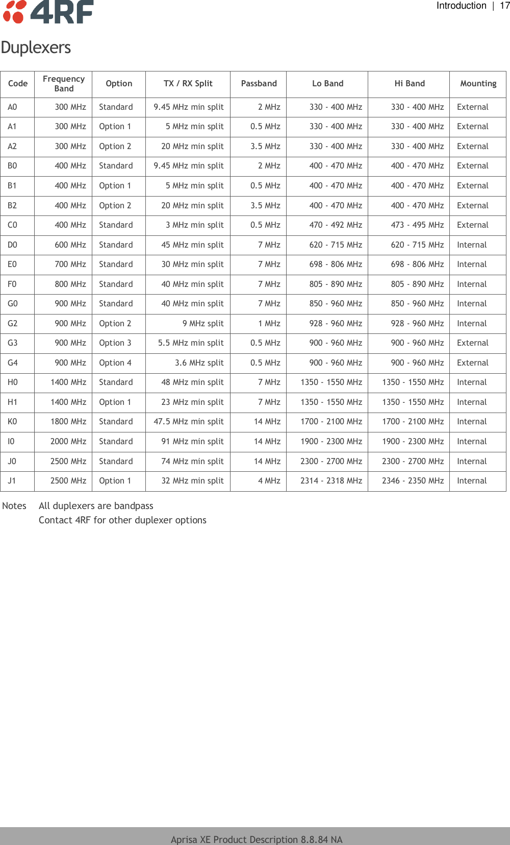
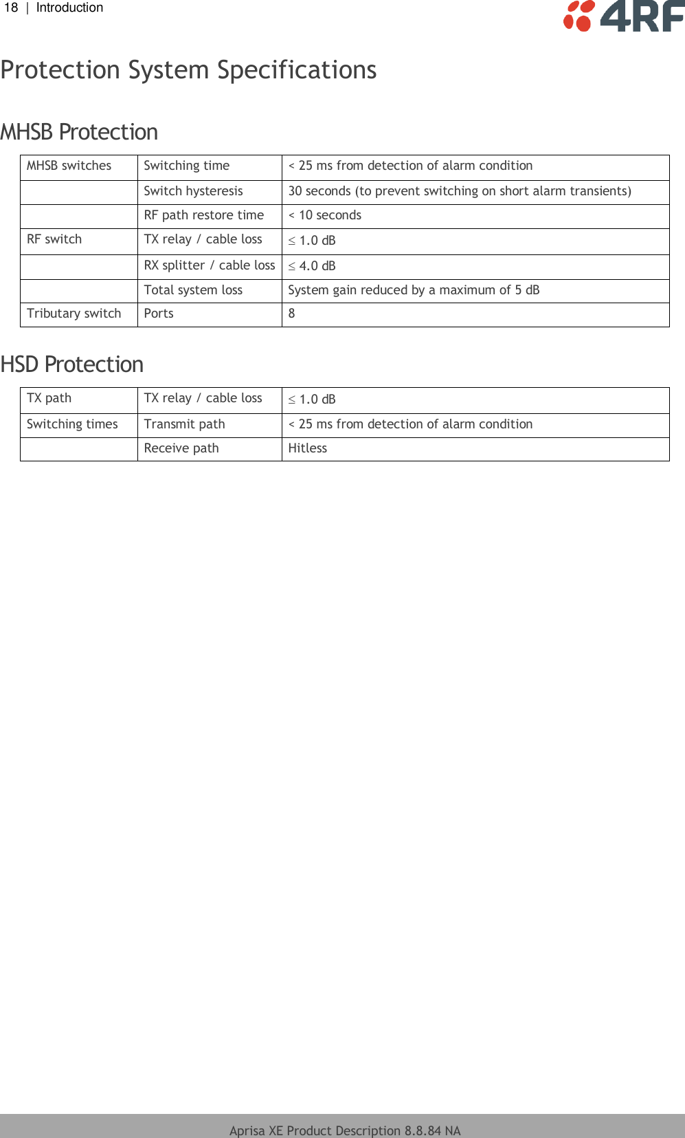
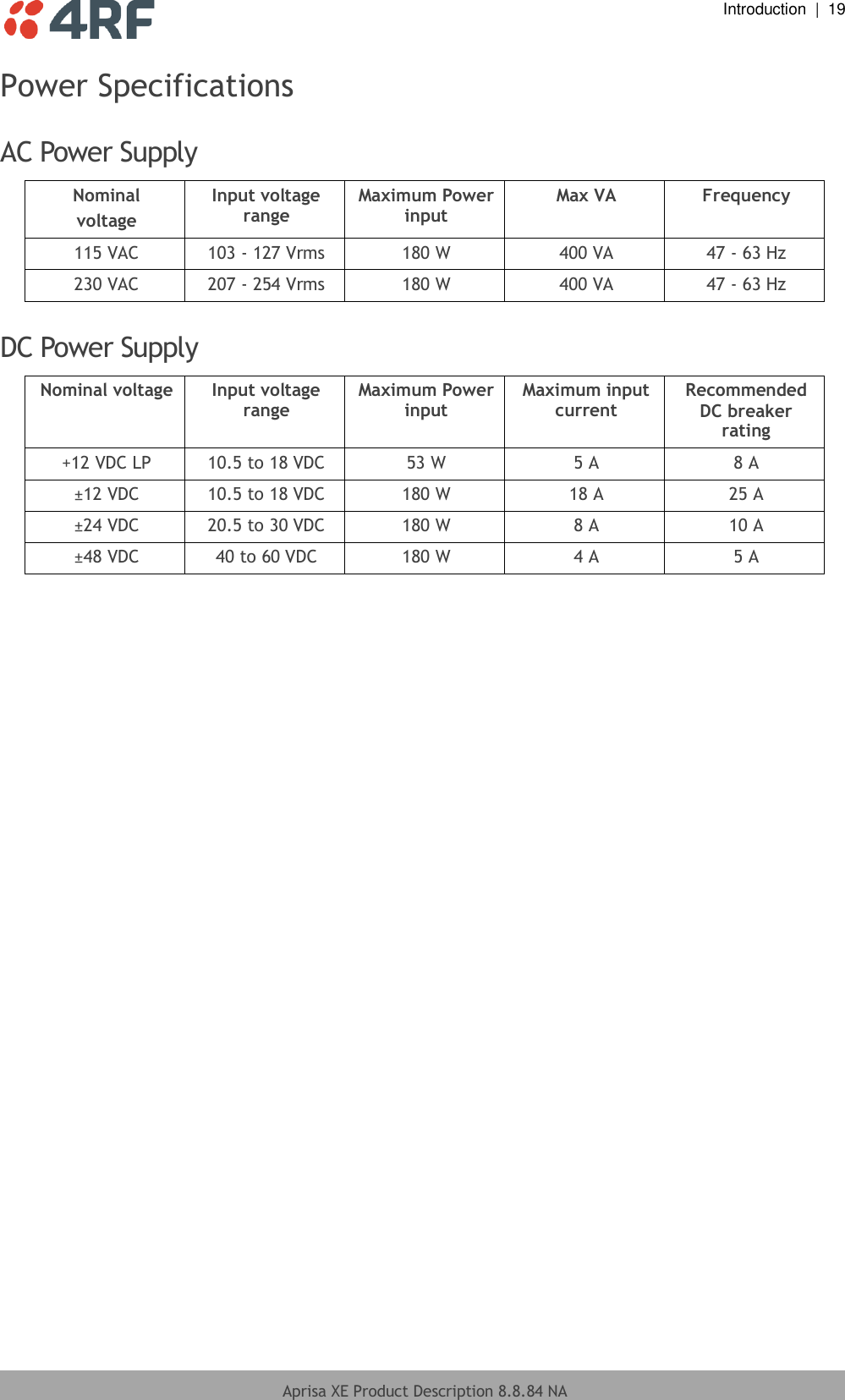
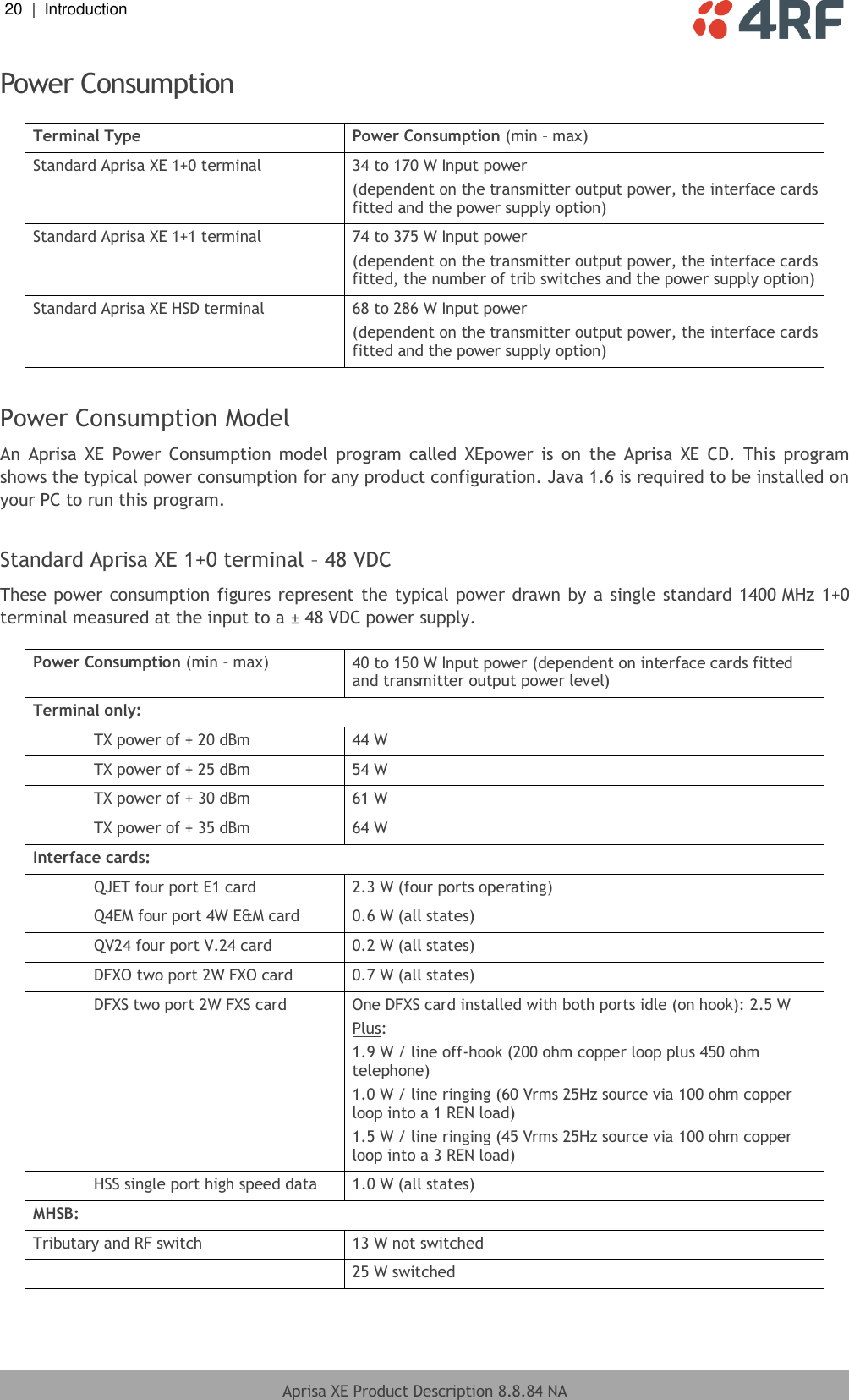
4RF Limited Digital Transceiver Aprisa XE Product Description 8 8 84 NA

User Manual

                                August 2017 Version 8.8.84a
   Aprisa XE Product Description 8.8.84 NA  Copyright Copyright © 2017 4RF Limited. All rights reserved.  This  document  is  protected  by  copyright  belonging  to  4RF  Limited  and  may  not  be  reproduced  or republished in whole or part in any form without the prior written permission of 4RF Limited.   Trademarks Aprisa and the 4RF logo are trademarks of 4RF Limited.  Windows is a registered trademark of Microsoft Corporation in the United States and other countries. Java and all Java-related trademarks are trademarks or registered trademarks of Sun Microsystems, Inc. in the United States and other countries. All other marks are the property of their respective owners. GoAhead WebServer. Copyright © 2000 GoAhead Software, Inc. All Rights Reserved. Disclaimer Although every precaution has been taken preparing this information, 4RF Limited assumes no liability for errors  and  omissions,  or  any  damages  resulting  from  use  of  this  information.  This  document  or  the equipment may change, without notice, in the interests of improving the product. RoHS and WEEE compliance The Aprisa XE is fully compliant with the European Commission’s RoHS (Restriction of Certain Hazardous Substances in Electrical and Electronic Equipment) and WEEE (Waste Electrical and Electronic Equipment) environmental directives.  Restriction of hazardous substances (RoHS) The  RoHS  Directive  prohibits  the  sale  in  the  European  Union  of  electronic  equipment  containing  these hazardous substances: lead*, cadmium, mercury, hexavalent chromium, polybrominated biphenyls (PBBs), and polybrominated diphenyl ethers (PBDEs). 4RF Limited has worked with its component suppliers to ensure compliance with the RoHS Directive which came into effect on the 1st July 2006.  *The European Commission Technical Adaptation Committee (TAC) has exempted lead in solder for high-reliability applications for which viable lead-free alternatives have not yet been identified. The exemption covers  communications  network  infrastructure  equipment,  which  includes  4RF  Limited’  Aprisa  XE microwave radios.  End-of-life recycling programme (WEEE) The WEEE Directive concerns the recovery, reuse, and recycling of electronic and electrical equipment. Under the Directive, used equipment must be marked, collected separately, and disposed of properly. 4RF  Limited  has  instigated  a  programme  to  manage  the  reuse,  recycling,  and  recovery  of  waste  in  an environmentally safe manner using processes that comply with the WEEE Directive (EU Waste Electrical and Electronic Equipment 2002/96/EC). 4RF  Limited  invites  questions  from  customers  and  partners  on  its  environmental  programmes  and compliance with the European Commission’s Directives (sales@4RF.com).
   Aprisa XE Product Description 8.8.84 NA  Compliance general The Aprisa XE digital radio predominantly operates within frequency bands that require a site license be issued  by  the  radio  regulatory  authority  with  jurisdiction  over  the  territory  in  which  the  equipment  is being operated. It  is  the responsibility of the user, before operating the  equipment, to  ensure that  where required the appropriate license has been granted and all conditions attendant to that license have been met. Changes  or  modifications  not  approved  by  the  party  responsible  for  compliance  could  void  the  user’s authority to operate the equipment. Equipment  authorizations  sought  by  4RF  Limited  are  based  on  the  Aprisa  XE  radio  equipment  being installed at a fixed restricted access location and operated in a continuous point-to-point mode within the environmental profile  defined  by EN 300 019,  Class 3.2.  Operation  outside  these  criteria may  invalidate the authorizations and / or license conditions. The term ‘Terminal’ with reference to the Aprisa XE User Manual, is a generic term for one end of a fixed point-to-point Aprisa XE link and does not confer any rights to connect to any public network or to operate the equipment within any territory.
   Aprisa XE Product Description 8.8.84 NA  Compliance FCC The Aprisa XE radio terminal is designed to comply with the Federal Communications Commission (FCC) specifications as follows:  Radio  47CFR part 90 Private Land Mobile Radio Services 47CFR part 101 Fixed Microwave Services 47CFR part 27 Misc Wireless Communication Services EMC 47CFR part 15 Radio Frequency Devices Environmental EN 300 019, Class 3.4 Safety EN 60950-1:2006   Frequency band limits Channel size Power input Authorization FCC ID 421 to 512 MHz 25 kHz 48 VDC Part 90 Certification UIPN0400025A0200A Lower 700 MHz 698 to 746 MHz 500 kHz, 1.0 MHz 1.75 MHz 24 VDC, 48 VDC, 110 VAC Part 27 Certification UIPN0700AAAA0000A Upper Block A 700 MHz 757 to 758 MHz 787 to 788 MHz 100 kHz, 200 kHz 500 kHz 24 VDC, 48 VDC, 110 VAC Part 27 Certification Pending 932.5 to 960 MHz 100 kHz, 200 kHz 24 VDC, 48 VDC, 110 VAC Part 101 Verification - 2314.5 to 2317.5 MHz 2346.5 to 2349.5 MHz 250 kHz, 500 kHz 24 VDC, 48 VDC, 110 VAC Part 27 Certification UIPN2500AAAA0200A 2180 to 2290 MHz 500 kHz 110 VAC Part 101 Certification UIPXE20001300  NOTE: This equipment has been tested and found to comply with the limits for a Class A digital device, pursuant to part 15 of the FCC Rules. These limits are designed to provide reasonable protection against harmful  interference  when  the  equipment  is  operated  in  a  commercial  environment.  This  equipment generates, uses, and can radiate radio frequency energy and, if not installed and used in accordance with the  instruction  manual,  may  cause  harmful  interference  to  radio  communications.  Operation  of  this equipment  in  a  residential  area  is  likely  to  cause  harmful  interference  in  which  case  the  user  will  be required to correct the interference at his own expense.
   Aprisa XE Product Description 8.8.84 NA  Compliance Industry Canada The Aprisa XE radio terminal is designed to comply with Industry Canada (IC) specifications as follows:  Radio RSS-GEN RSS-119  EMC This Class A digital apparatus complies with Canadian standard ICES-003. Cet appareil numérique de la classe A est conforme à la norme NMB-003 du Canada. Environmental EN 300 019, Class 3.4 Safety EN 60950-1:2006   Frequency Band Channel size Power input Authorization IC ID 406.1 to 430 MHz and 450 to 470 MHz 25 kHz, 50 kHz 75 kHz, 150 kHz 24 VDC, 48 VDC, 110 VAC RSS-119 6772A-N04AAAEC 932.5 to 944 MHz 100 kHz, 200 kHz 24 VDC, 48 VDC, 110 VAC RSS-119 6772A-N09AAACC 1427 to 1452 MHz and 1492 to 1518 MHz 3.50 MHz 24 VDC, 48 VDC, 110 VAC SRSP-301.4  2025 to 2110 MHz and 2200 to 2285 MHz 500 kHz, 1.0 MHz, 1.75 MHz, 3.50 MHz, 7 MHz 24 VDC, 48 VDC, 110 VAC SRSP-302.0
DRAFT   Aprisa XE Product Description 8.8.84 NA  RF Exposure Warning   WARNING: The installer and / or user of Aprisa XE radio terminals shall ensure that a separation distance as given in the following table is maintained between the main axis of the terminal’s antenna and the body of the user or nearby persons. Minimum  separation  distances  given  are  based  on  the  maximum  values  of  the following methodologies: 1.  Maximum Permissible Exposure non-occupational limit (B or general public) of 47 CFR 1.1310 and the methodology of FCC’s OST/OET Bulletin number 65.  2.  Reference levels as given in Annex III, European Directive on the limitation of exposure of  the  general  public  to  electromagnetic fields (0 Hz  to  300 GHz) (1999/519/EC).  These  distances  will  ensure  indirect  compliance  with  the requirements of EN 50385:2002.    Frequency (MHz) Maximum power (dBm) Maximum antenna gain (dBi) Maximum power density (mW/cm2) Minimum separation distance (m) 400 + 35 15 0.20 2.0 512 + 35 15 0.26 1.8 806 + 34 28 0.40 5.6 890 + 34 28 0.45 5.3 960 + 34 28 0.48 5.1 1550 + 34 33 0.78 7.2 2300 + 34 37 1.00 10.0 2700 + 34 38 1.00 11.2  715 + 34 10 0.23 1.0
   Aprisa XE Product Description 8.8.84 NA  Contents 1. Introduction ................................................................................ 1 The 4RF Aprisa XE Terminal .................................................................... 1 Key Features ...................................................................................... 2 Robust Transmission Performance ...................................................... 3 Flexible Multiplexing ...................................................................... 3 Interface Types ............................................................................ 3 In-built Cross-Connect .................................................................... 4 RF Specifications ................................................................................. 5 Radios FCC.................................................................................. 5 Radios IC ................................................................................... 11 Duplexers .................................................................................. 17 Protection System Specifications ............................................................. 18 MHSB Protection .......................................................................... 18 HSD Protection ............................................................................ 18 Power Specifications ............................................................................ 19 AC Power Supply .......................................................................... 19 DC Power Supply.......................................................................... 19 Power Consumption ...................................................................... 20 Environmental ............................................................................ 22 Mechanical ................................................................................ 22 Compliance ................................................................................ 23 2. Applications .............................................................................. 25 Extending Telecommunications and Cellular Networks .................................... 26 Delivering POTS and Broadband to Remote Subscribers ................................... 27 Extending DSL Services in Remote Areas..................................................... 28 Supporting Mobile Radio Networks............................................................ 29 Digital Mobile Radio Networks .......................................................... 29 Analogue Trunked Radio................................................................. 29 Conventional Radio ...................................................................... 30 Supporting Utility Networks ................................................................... 31 Linking Offices in Private Networks .......................................................... 32
   Aprisa XE Product Description 8.8.84 NA  3. Architecture ............................................................................. 33 Modules ........................................................................................... 33 Front Panel Connections and Indicators ..................................................... 35 Transceiver ....................................................................................... 36 Receiver ................................................................................... 36 Transmitter................................................................................ 37 Duplexer .......................................................................................... 37 Modem ............................................................................................ 38 Motherboard ..................................................................................... 39 Power Supplies................................................................................... 40 AC Power Supply .......................................................................... 40 DC Power Supply.......................................................................... 40 Mounting Options ................................................................................ 40 Heat Dissipation ................................................................................. 40 4. Interfaces ................................................................................. 41 Interface Specifications ........................................................................ 41 Ethernet Interface Connections ............................................................... 41 QETH Interface Connections ................................................................... 42 QJET Quad E1 / T1 Interface ........................................................... 44 Q4EM Quad 4 Wire E&M Interface ...................................................... 45 DFXO Dual Foreign Exchange Office Interface ....................................... 49 DFXS Dual Foreign Exchange Subscriber Interface ................................... 51 QV24 Quad V.24 Serial Data Interface ................................................ 53 HSS Single High Speed Synchronous Interface ........................................ 55 5. SuperVisor ................................................................................ 59 Configuring the Aprisa XE Terminal........................................................... 59 Monitoring the Aprisa XE Terminal............................................................ 59 Operator Rights and Access Levels............................................................ 60 Viewing the Status of the Link ................................................................ 60 Configuring the Basic Terminal Settings ..................................................... 61 Configuring the Interface Ports and Cross Connect ........................................ 62 Interface Ports ............................................................................ 62 Loopback Functionality .................................................................. 63 Configuring the Cross Connects ........................................................ 63 Monitoring Performance and Troubleshooting Problems .................................. 64 6. Network Management .................................................................. 67 7. Protected Options ...................................................................... 69 Monitored Hot Stand By (MHSB) ............................................................... 69 Hitless Space Diversity (HSD) .................................................................. 71
 Introduction  |  1  Aprisa XE Product Description 8.8.84 NA  1. Introduction The 4RF Aprisa XE Terminal The  4RF  Aprisa  XE  point-to-point  digital  access  radio  provides  robust  wireless  transmission  of  Internet, voice and data traffic over distances of up to 250 kilometres.  The  Aprisa  XE  Terminal  is  the  flexible,  functional  answer  to  the  low-medium  capacity  challenges  in today’s wireless networks. Easy  to  use  and  customer-configurable,  the  Aprisa  XE  terminal  provides  solutions  from  simple  trunking applications to complete complex network designs. Our  design  priority  is  to  reduce  network  operators’  costs.  To  this  end,  we  engineer  into  all  Aprisa  XE terminals high-performance characteristics and operating features that deliver:  Superior spectral efficiency  Customer-configurable interfaces  Straightforward integration into existing networks  The SuperVisorTM software is an embedded element manager for the Aprisa XE terminal, meaning that is easily accessed using any standards-compliant web browser. The SuperVisor software is graphical and intuitive, and requires no ongoing training. SNMP connectivity is standard with  the  SuperVisor software, allowing easy integration of  the  Aprisa XE  terminal into  higher-level management systems. The Aprisa XE terminal is small and powerful, with eight interface slots and up to 65 Mbit/s of capacity, ideal for use in busy network sites where vertical rack space is limited.
2  |  Introduction   Aprisa XE Product Description 8.8.84 NA     Key Features  Spectrally efficient 16, 32 and 64 QAM modulation types  QPSK modulation for higher system gain  Capacities from 72 kbit/s (1 x timeslot) to 65 Mbit/s (32 x E1)  Channel sizes from 25 kHz to 14 MHz  A full E1 (2 Mbit/s) bearer in just 500 kHz of spectrum (64 QAM)  In-built 4-port Ethernet switch  In-built digital cross-connect with 8 kbit/s granularity  Frequency bands from 300 MHz to 2.7 GHz  Customer-configurable interface options for data and voice traffic  19-inch rack mounting  Complies with international standards, including ETSI, FCC and Industry Canada  Modular design to reduce the mean time to repair (MTTR)  Embedded Java™-enabled element management software (the SuperVisor software)  Integrated SNMP for network management  Protection options of Monitored Hot Standby (MHSB) and Hitless Space Diversity (HSD)
 Introduction  |  3  Aprisa XE Product Description 8.8.84 NA  Robust Transmission Performance The  Aprisa  XE  terminal  provides  robust,  reliable,  ‘carrier-class’  transmission  performance  for  long  and challenging paths:  Reed-Solomon  Forward  Error  Correction  delivers  an  unfaded  BER  of  10-12  ,  a  performance  more commonly associated with fibre optics.  Multi-tap equalizers optimize multi-path performance.  Advanced  digital  filters  provide  optimum  protection  against  adjacent  channel  interference,  and allow maximum frequency reuse.  Spectrum-efficient  16,  32  and  64  QAM  modulation  maximizes  data  throughput  in  narrow  radio channels, thereby reducing frequency licensing costs.  QPSK modulation provides increased gain for very long obstructed paths.  Flexible Multiplexing The Aprisa XE terminal provides primary multiplexing options without the need for external equipment. It features eight interface card slots and an in-built cross-connect.  Interface Types The  Aprisa  XE  terminal’s  range  of  analogue  and  digital  customer  interface  types  makes  it  suitable  for many applications. It comes with an in-built 4-port Ethernet switch, which supports VLAN tagging and QoS for customer and management traffic.  Other interface card options include:  QETH Quad port Ethernet interface card supporting 10Base-T or 100Base-TX for transport of user Ethernet traffic  DFXO Dual 2 wire Foreign Exchange Office (PCM / ADPCM)  DFXS Dual 2 wire Foreign Exchange Subscriber (PCM / ADPCM)  Q4EM Quad 4 wire E&M (PCM / ADPCM)  QJET Quad E1 / T1 - G.703 / G.704  QV24 Quad V.24 asynchronous and synchronous Serial Data Interface.  HSS Single Synchronous Serial interface including V.35, X.21, RS-449 and RS-530
4  |  Introduction   Aprisa XE Product Description 8.8.84 NA  In-built Cross-Connect The Aprisa XE terminal’s in-built micro cross-connect distributes capacity to each of the interfaces. It can distribute traffic  to any of  the possible 32 interface ports as well as the integrated  Ethernet  interface. This allows operators to reconfigure traffic as network demand changes, and to groom user traffic onto E1 bearers between equipment. For example, a typical E1 bearer can be distributed as follows:  Four 64 kbit/s PCM 2 wire voice circuits  CAS signalling using 64 kbit/s  Four 9600 bit/s V.24 circuits, each using 24 kbit/s  One X.21 circuit using 128 kbit/s  One Ethernet 100/10Base-T circuit using 384 kbit/s  16 timeslots for fractional E1 traffic using 1024 kbit/s  One management channel using 64 kbit/s
 Introduction  |  5  Aprisa XE Product Description 8.8.84 NA  RF Specifications  Radios FCC  Frequency Bands FCC  Frequency Bands Frequency Band Frequency Tuning Range Synthesizer Step Size   400 MHz 421 - 512 MHz 6.25 kHz   Lower 700 MHz 698 - 746 MHz 12.5 kHz   Upper Block A  700 MHz 757 – 758 and  787 – 788 MHz 12.5 kHz   900 MHz 928 - 960 MHz 12.5 kHz   1800 MHz 1755 - 1850 MHz 62.5 kHz   2000 MHz 1900 - 2300 MHz 62.5 kHz   2500 MHz  250 / 500 kHz channels 2314 - 2350 MHz 62.5 kHz   2500 MHz All other channels 2305 - 2360 MHz 62.5 kHz  Modulation 16 / 32 / 64 QAM and QPSK (software configurable) Frequency stability (short term) < ±1 ppm Frequency stability (long term) < ±2 ppm Antenna connector N-type female 50 Ω  Notes  Frequency Ranges Country specific frequency ranges within the above tuning ranges can be accommodated  Frequency stability Short term frequency stability is defined as changes in frequency due to environmental effects and power supply variations Long term frequency stability is defined as changes in frequency due to aging of crystal oscillators approx over 5 years
6  |  Introduction   Aprisa XE Product Description 8.8.84 NA  Product Range FCC The Aprisa XE terminal provides the following FCC frequency bands / channel sizes:    Channel Size   kHz MHz                   Frequency Band MHz  25 50 100 200 250 500 1.00 1.75 400 Part 90                        700     Part 27 Part 27   Part 27 Part 27 Part 27          900 Part 101 Part 101 Part 101 Part 101                  2500         Part 27 Part 27                            Released                     Product Release Pending
 Introduction  |  7  Aprisa XE Product Description 8.8.84 NA  Link Capacity FCC part 27  Channel size  QPSK 16 QAM 32 QAM 64 QAM 100 kHz Gross 168 kbit/s 344 kbit/s 432 kbit/s 520 kbit/s   T1 2 timeslots 5 timeslots 6 timeslots 8 timeslots  Wayside 40 kbit/s 24 kbit/s 48 kbit/s 8 kbit/s 200 kHz Gross 336 kbit/s 680 kbit/s 840 kbit/s 1024 kbit/s   T1 5 timeslots 10 timeslots 13 timeslots 16 timeslots   Wayside 16 kbit/s 40 kbit/s 8 kbit/s 0 kbit/s 250 kHz Gross 408 kbit/s 824 kbit/s 1032 kbit/s 1240 kbit/s   T1 6 timeslots 12 timeslots 16 timeslots 19 timeslots   Wayside 24 kbit/s 56 kbit/s 8 kbit/s 24 kbit/s 500 kHz Gross 792 kbit/s 1592 kbit/s 1992 kbit/s 2392 kbit/s   T1 12 timeslots 1 T1 1 T1 1 T1   Wayside 24 kbit/s 8 kbit/s 408 kbit/s 808 kbit/s 1.0 MHz Gross 1656 kbit/s 3320 kbit/s 4152 kbit/s 4984 kbit/s   T1 1 T1 2 T1s 2 T1s 3 T1s   Wayside 72 kbit/s 152 kbit/s 984 kbit/s 232 kbit/s 1.75 MHz Gross 2872 kbit/s 5752 kbit/s 7192 kbit/s 8632 kbit/s   T1 1 T1 3 T1s 4 T1s 5 T1s   Wayside 1288 kbit/s 1000 kbit/s 856 kbit/s 712 kbit/s  Link Capacity FCC part 90  Channel size  QPSK 16 QAM 32 QAM 64 QAM 25 kHz Gross   56 kbit/s 72 kbit/s 88 kbit/s   T1   0 timeslots 1 timeslot 1 timeslot  Wayside   56 kbit/s 8 kbit/s 24 kbit/s  Link Capacity FCC part 101  Channel size  QPSK 16 QAM 32 QAM 64 QAM 25 kHz Gross   72 kbit/s 96 kbit/s 112 kbit/s   T1   1 timeslot 1 timeslot 1 timeslot   Wayside   8 kbit/s 32 kbit/s 48 kbit/s 50 kHz Gross 80 kbit/s 168 kbit/s 208 kbit/s 256 kbit/s   T1 1 timeslot 2 timeslots 3 timeslots 4 timeslots  Wayside 16 kbit/s 40 kbit/s 16 kbit/s 0 kbit/s 100 kHz Gross 136 kbit/s 280 kbit/s 352 kbit/s 424 kbit/s   T1 2 timeslots 4 timeslots 5 timeslots 6 timeslots  Wayside 8 kbit/s 24 kbit/s 32 kbit/s 40 kbit/s 200 kHz Gross 312 kbit/s 632 kbit/s 792 kbit/s 952 kbit/s   T1 4 timeslots 9 timeslots 12 timeslots 14 timeslots   Wayside 56 kbit/s 56 kbit/s 24 kbit/s 56 kbit/s  Notes  The capacities specified are for unframed T1 and so require 1584 kbit/s to transport via the radio.   The management ethernet capacity must be subtracted from the gross capacity (default 64 kbit/s).   See Product Range table for Channel Size / Frequency Band cross reference    NA (Not Available)
8  |  Introduction   Aprisa XE Product Description 8.8.84 NA  Receiver Sensitivity FCC  Channel size QPSK 16 QAM 32 QAM 64 QAM 25 kHz NA -105 dBm -102 dBm -99 dBm 50 kHz -109 dBm -103 dBm -100 dBm -97 dBm 100 kHz -106 dBm -100 dBm -97 dBm -94 dBm 200 kHz -102 dBm -96 dBm -93 dBm -90 dBm 250 kHz -101 dBm -95 dBm -92 dBm -89 dBm 500 kHz -99 dBm -93 dBm -90 dBm -87 dBm 1.0 MHz -96 dBm -90 dBm -87 dBm -84 dBm 1.75 MHz -94 dBm -88 dBm -85 dBm -82 dBm  Notes  Typical performance specified at the antenna port for 10-6 BER.   The receiver is typically 1 dB more sensitive for a BER of 10-3.   NA (Not Available)  Transmitter Power FCC  1+0 Radio  Frequency Band QPSK 16 QAM 32 QAM 64 QAM 400 MHz NA 17 to 31 dBm 15 to 29 dBm 15 to 29 dBm Lower 700 MHz 21 to 35 dBm 17 to 31 dBm 15 to 29 dBm 15 to 29 dBm Upper 700 MHz 21 to 31 dBm 17 to 31 dBm 15 to 29 dBm 15 to 29 dBm 700 MHz 21 to 35 dBm 17 to 31 dBm 15 to 29 dBm 15 to 29 dBm 900 MHz 15 to 29 dBm 15 to 29 dBm 15 to 29 dBm 15 to 29 dBm 2500 MHz 15 to 29 dBm 15 to 29 dBm 15 to 29 dBm 15 to 29 dBm  1+1 Radio  Frequency Band QPSK 16 QAM 32 QAM 64 QAM 400 MHz NA 15 to 29 dBm 15 to 29 dBm 15 to 28 dBm Lower 700 MHz 21 to 35 dBm 15 to 29 dBm 15 to 29 dBm 15 to 28 dBm Upper 700 MHz 21 to 31 dBm 15 to 29 dBm 15 to 29 dBm 15 to 28 dBm 900 MHz 15 to 28 dBm 15 to 28 dBm 15 to 28 dBm 15 to 28 dBm 2500 MHz 15 to 28 dBm 15 to 28 dBm 15 to 28 dBm 15 to 28 dBm
 Introduction  |  9  Aprisa XE Product Description 8.8.84 NA  System Gain FCC  Frequency Band Channel size QPSK 16 QAM 32 QAM 64 QAM 400 MHz 25 kHz NA 136 dB 132 dB 128 dB Upper 700 MHz 100 kHz 137 dB 131 dB 127 dB 123 dB Upper 700 MHz 200 kHz 133 dB 127 dB 123 dB 119 dB Lower 700 MHz 500 kHz 134 dB 124 dB 120 dB 116 dB Upper 700 MHz 500 kHz 130 dB 124 dB 120 dB 116 dB Lower 700 MHz 1.0 MHz 131 dB 121 dB 117 dB 113 dB Lower 700 MHz 1.75 MHz 129 dB 119 dB 115 dB 111 dB 900 MHz 25 kHz NA 134 dB 131 dB 128 dB 900 MHz 50 kHz 138 dB 132 dB 129 dB 126 dB 900 MHz 100 kHz 135 dB 129 dB 126 dB 123 dB 900 MHz 200 kHz 131 dB 125 dB 122 dB 119 dB 2500 MHz 250 kHz 130 dB 124 dB 121 dB 118 dB 2500 MHz 500 kHz 128 dB 122 dB 119 dB 116 dB  Notes  Typical performance specified at the antenna port for 10-6 BER.   The system gain is typically 1 dB greater for a BER of 10-3.   System Gain = maximum transmit power - receiver sensitivity    NA (Not Available)  Receiver Performance FCC  Maximum input level -20 dBm Dynamic range 58 to 87 dB (at 10-6 BER) depending on modulation type and channel size  C/I ratio (carrier to interference ratio) C/I ratio =  CdB - IdB   Co-channel better than 16 dB at QPSK     better than 20 dB at 16 QAM     better than 23 dB at 32 QAM     better than 27 dB at 64 QAM         1st adjacent channel better than -5 dB   2nd adjacent channel better than -30 dB  Notes  Typical performance specified at the antenna port for 10-6 BER.   The dynamic range is typically 2 dB greater for a BER of 10-3
10  |  Introduction   Aprisa XE Product Description 8.8.84 NA  Link Delays FCC  Note: The default Modem Interleaver Mode setting is on for channel sizes of 250 kHz and greater and off for channel sizes of 200 kHz and less.  Typical 1+0, MHSB end-to-end link delay - interleaver off  Channel size QPSK 16 QAM 32 QAM 64 QAM FCC Part 25 kHz NA 64.4 ms 52.3 ms 44.2 ms Part 90 25 kHz NA 51.8 ms 40.6 ms 35.7 ms Part 101 50 kHz 46.2 ms 24.3 ms 20.2 ms 16.9 ms Part 101 100 kHz 28.8 ms 15.3 ms 12.7 ms 10.9 ms Part 101 200 kHz 15.9 ms 8.8 ms 7.3 ms 6.4 ms Part 101 250 kHz 10.8 ms 6.5 ms 5.5 ms 4.9 ms Part 27 500 kHz 6.3 ms 3.9 ms 3.4 ms 7.1 ms Part 27 1.0 MHz 3.8 ms 2.6 ms 2.3 ms 2.2 ms Part 27 1.75 MHz 3.1 ms 2.3 ms 2.1 ms 2.0 ms Part 27  Typical 1+0, MHSB end-to-end link delay - interleaver on  Channel size QPSK 16 QAM 32 QAM 64 QAM FCC Part 25 kHz NA 191.6 ms 154.1 ms 129.1 ms Part 90 25 kHz NA 153.6 ms 118.9 ms 103.5 ms Part 101 50 kHz 138.8 ms 70.5 ms 57.9 ms 47.8 ms Part 101 100 kHz 85.3 ms 43.6 ms 35.3 ms 29.7 ms Part 101 200 kHz 45.8 ms 23.7 ms 19.3 ms 16.4 ms Part 101 250 kHz 30.4 ms 17.7 ms 14.5 ms 12.4 ms Part 27 500 kHz 16.5 ms 9.5 ms 8.2 ms 3.2 ms Part 27 1.0 MHz 8.8 ms 5.1 ms 4.3 ms 3.9 ms Part 27 1.75 MHz 5.6 ms 3.5 ms 3.1 ms 2.8 ms Part 27  Notes  The end to end link delays are measured from T1 interface to T1 interface    The delay figures are typical and can vary when the system re-synchronizes   NA (Not Available)
 Introduction  |  11  Aprisa XE Product Description 8.8.84 NA  Radios IC Frequency Bands IC  Frequency Bands Frequency Band Frequency Tuning Range Synthesizer Step Size   400 MHz 400 - 470 MHz 6.25 kHz   900 MHz 928 - 960 MHz 12.5 kHz   2000 MHz 1900 - 2300 MHz 62.5 kHz  Modulation 16 / 32 / 64 QAM and QPSK (software configurable) Frequency stability (short term) < ±1 ppm Frequency stability (long term) < ±2 ppm Antenna connector N-type female 50 Ω  Notes  Frequency Ranges Country specific frequency ranges within the above tuning ranges can be accommodated  Frequency stability Short term frequency stability is defined as changes in frequency due to environmental effects and power supply variations Long term frequency stability is defined as changes in frequency due to aging of crystal oscillators approx over 5 years
12  |  Introduction   Aprisa XE Product Description 8.8.84 NA  Product Range IC The Aprisa XE terminal provides the following IC frequency bands / channel sizes:     Channel Size   kHz MHz                             25 50 75 100 150 200 500 1.00 1.75 3.50 7.00 14.00 Frequency Band MHz 400 RSS 119 RSS 119 RSS 119   RSS 119                            900       RSS 119   RSS 119                          2000             SRSP-302 SRSP-302 SRSP-302 SRSP-302 SRSP-302 SRSP-302
 Introduction  |  13  Aprisa XE Product Description 8.8.84 NA  Link Capacity IC  Channel size  QPSK 16 QAM 32 QAM 64 QAM 25 kHz Gross NA 56 kbit/s 72 kbit/s 88 kbit/s   T1   0 timeslots 1 timeslot 1 timeslot   Wayside   56 kbit/s 8 kbit/s 24 kbit/s 50 kHz Gross 72 kbit/s 152 kbit/s 192 kbit/s 232 kbit/s   T1 1 timeslot 2 timeslots 3 timeslots 4 timeslots   Wayside 8 kbit/s 24 kbit/s 0 kbit/s 40 kbit/s 75 kHz Gross 128 kbit/s 264 kbit/s 312 kbit/s 400 kbit/s   T1 2 timeslots 4 timeslots 4 timeslots 6 timeslots   Wayside 0 kbit/s 8 kbit/s 56 kbit/s 16 kbit/s 100 kHz Gross 136 kbit/s 280 kbit/s 352 kbit/s 424 kbit/s   T1 2 timeslots 4 timeslots 5 timeslots 6 timeslots   Wayside 8 kbit/s 24 kbit/s 32 kbit/s 40 kbit/s 150 kHz Gross 264 kbit/s 536 kbit/s 672 kbit/s 808 kbit/s   T1 4 timeslots 8 timeslots 10 timeslots 12 timeslots   Wayside 8 kbit/s 24 kbit/s 32 kbit/s 40 kbit/s 200 kHz Gross 312 kbit/s 632 kbit/s 792 kbit/s 952 kbit/s   T1 4 timeslots 9 timeslots 12 timeslots 14 timeslots   Wayside 56 kbit/s 56 kbit/s 24 kbit/s 56 kbit/s 500 kHz Gross 792 kbit/s 1592 kbit/s 1992 kbit/s 2392 kbit/s   T1 12 timeslots 1 T1 1 T1 1 T1   Wayside 24 kbit/s 8 kbit/s 408 kbit/s 808 kbit/s 1.0 MHz Gross 1624 kbit/s 3256 kbit/s 4072 kbit/s 4888 kbit/s   T1 1 T1 2 T1s 2 T1s 3 T1s   Wayside 40 kbit/s 88 kbit/s 904 kbit/s 136 kbit/s 1.75 MHz Gross 2872 kbit/s 5752 kbit/s 7192 kbit/s 8632 kbit/s   T1 1 T1 3 T1s 4 T1s 5 T1s   Wayside 1288 kbit/s 1000 kbit/s 856 kbit/s 712 kbit/s 3.5 MHz Gross 5720 kbit/s 11448 kbit/s 14312 kbit/s 17176 kbit/s   T1 3 T1s 7 T1s 9 T1s 10 T1s   Wayside 968 kbit/s 360 kbit/s 56 kbit/s 1336 kbit/s 7.0 MHz Gross 11832 kbit/s 23672 kbit/s 29592 kbit/s 35512 kbit/s   T1 7 T1s 14 T1s 18 T1s 22 T1s   Wayside 744 kbit/s 1496 kbit/s 1080 kbit/s 664 kbit/s 14 MHz Gross NA 47992 kbit/s 59992 kbit/s 65464 kbit/s   T1   30 T1s 32 T1s 32 T1s   Wayside   472 kbit/s 9304 kbit/s 14776 kbit/s  Notes  The capacities specified are for unframed T1 and so require 1584 kbit/s to transport via the radio.   The management ethernet capacity must be subtracted from the gross capacity (default 64 kbit/s).   See Product Range table for Channel Size / Frequency Band cross reference    NA (Not Available)
14  |  Introduction   Aprisa XE Product Description 8.8.84 NA  Receiver Sensitivity IC  Channel size QPSK 16 QAM 32 QAM 64 QAM 25 kHz NA -105 dBm -102 dBm -99 dBm 50 kHz -109 dBm -103 dBm -100 dBm -97 dBm 75 kHz -107 dBm -101 dBm -98 dBm -95 dBm 100 kHz -106 dBm -100 dBm -97 dBm -94 dBm 150 kHz -104 dBm -98 dBm -95 dBm -92 dBm 200 kHz -102 dBm -96 dBm -93 dBm -90 dBm 500 kHz -99 dBm -93 dBm -90 dBm -87 dBm 1.0 MHz -96 dBm -90 dBm -87 dBm -84 dBm 1.75 MHz -94 dBm -88 dBm -85 dBm -82 dBm 3.5 MHz -90 dBm -84 dBm -81 dBm -78 dBm 7.0 MHz -87 dBm -81 dBm -78 dBm -75 dBm 14 MHz NA -78 dBm -75 dBm -72 dBm  Notes  Typical performance specified at the antenna port for 10-6 BER.   The receiver is typically 1 dB more sensitive for a BER of 10-3.   NA (Not Available)  Transmitter Power IC  Frequency Band QPSK 16 QAM 32 QAM 64 QAM 400 MHz 21 to 35 dBm 17 to 31 dBm 16 to 30 dBm 15 to 29 dBm 900 MHz 15 to 29 dBm 15 to 29 dBm 15 to 29 dBm 15 to 29 dBm 2000 MHz 20 to 34 dBm 17 to 31 dBm 16 to 30 dBm 15 to 29 dBm
 Introduction  |  15  Aprisa XE Product Description 8.8.84 NA  System Gain IC  Channel size QPSK 16 QAM 32 QAM 64 QAM 25 kHz NA 136 dB 132 dB 128 dB 50 kHz 144 dB 134 dB 130 dB 126 dB 75 kHz 142 dB 132 dB 128 dB 124 dB 100 kHz 135 dB 129 dB 126 dB 123 dB 150 kHz 139 dB 129 dB 125 dB 121 dB 200 kHz 131 dB 125 dB 122 dB 119 dB 500 kHz 133 dB 124 dB 120 dB 116 dB 1.0 MHz 130 dB 121 dB 117 dB 113 dB 1.75 MHz 128 dB 119 dB 115 dB 111 dB 3.5 MHz 124 dB 115 dB 111 dB 107 dB 7.0 MHz 121 dB 112 dB 108 dB 104 dB 14 MHz NA 109 dB 105 dB 101 dB  Notes  Typical performance specified at the antenna port for 10-6 BER.   The system gain is typically 1 dB greater for a BER of 10-3.  System Gain = maximum transmit power - receiver sensitivity    NA (Not Available)  Receiver Performance  Maximum input level -20 dBm Dynamic range 58 to 87 dB (at 10-6 BER) depending on modulation type and channel size  C/I ratio (carrier to interference ratio) C/I ratio =  CdB - IdB   Co-channel better than 16 dB at QPSK     better than 20 dB at 16 QAM     better than 23 dB at 32 QAM     better than 27 dB at 64 QAM         1st adjacent channel better than -5 dB   2nd adjacent channel better than -30 dB  Notes  Typical performance specified at the antenna port for 10-6 BER.   The dynamic range is typically 2 dB greater for a BER of 10-3
16  |  Introduction   Aprisa XE Product Description 8.8.84 NA  Link Delays IC  Note: The default Modem Interleaver Mode setting is on for channel sizes of 250 kHz and greater and off for channel sizes of 200 kHz and less.  Typical 1+0, MHSB end-to-end link delay - interleaver off  Channel size QPSK 16 QAM 32 QAM 64 QAM 25 kHz NA 49.6 ms 39.4 ms 34.9 ms 50 kHz 46.2 ms 24.3 ms 20.2 ms 16.9 ms 75 kHz 35.5 ms 19.0 ms 16.8 ms 13.6 ms 100 kHz 28.8 ms 15.3 ms 12.7 ms 10.9 ms 150 kHz 17.5 ms 10.1 ms 8.5 ms 7.1 ms 200 kHz 15.9 ms 8.8 ms 7.3 ms 6.4 ms 500 kHz 6.3 ms 3.5 ms 3.4 ms 3.2 ms 1.0 MHz 3.8 ms 2.6 ms 2.3 ms 2.2 ms 1.75 MHz 3.1 ms 2.3 ms 2.1 ms 2.0 ms 3.5 MHz 2.6 ms 2.0 ms 1.8 ms 1.8 ms 7.0 MHz 2.0 ms 1.7 ms 1.6 ms 1.6 ms 14 MHz NA 1.6 ms 1.5 ms 1.5 ms  Typical 1+0, MHSB end-to-end link delay - interleaver on  Channel size QPSK 16 QAM 32 QAM 64 QAM 25 kHz NA 164.7 ms 127.7 ms 111.8 ms 50 kHz 138.8 ms 70.5 ms 59.9 ms 47.8 ms 75 kHz 103.7 ms 53.2 ms 45.8 ms 36.4 ms 100 kHz 85.3 ms 43.6 ms 35.3 ms 29.7 ms 150 kHz 51.4 ms 26.8 ms 21.9 ms 18.6 ms 200 kHz 45.8 ms 23.7 ms 19.3 ms 16.4 ms 500 kHz 16.5 ms 9.3 ms 8.0 ms 6.9 ms 1.0 MHz 8.8 ms 5.1 ms 4.3 ms 3.9 ms 1.75 MHz 6.8 ms 4.1 ms 3.6 ms 3.2 ms 3.5 MHz 5.1 ms 3.2 ms 2.8 ms 2.6 ms 7.0 MHz 3.5 ms 2.4 ms 2.2 ms 2.1 ms 14 MHz NA 2.1 ms 1.9 ms 1.8 ms   Notes  The end to end link delays are measured from T1 interface to T1 interface    The delay figures are typical and can vary when the system re-synchronizes   NA (Not Available)
 Introduction  |  17  Aprisa XE Product Description 8.8.84 NA  Duplexers  Code Frequency Band Option TX / RX Split Passband Lo Band Hi Band Mounting A0 300 MHz Standard 9.45 MHz min split 2 MHz 330 - 400 MHz 330 - 400 MHz External A1 300 MHz Option 1 5 MHz min split 0.5 MHz 330 - 400 MHz 330 - 400 MHz External A2 300 MHz Option 2 20 MHz min split 3.5 MHz 330 - 400 MHz 330 - 400 MHz External B0 400 MHz Standard 9.45 MHz min split 2 MHz 400 - 470 MHz 400 - 470 MHz External B1 400 MHz Option 1 5 MHz min split 0.5 MHz 400 - 470 MHz 400 - 470 MHz External B2 400 MHz Option 2 20 MHz min split 3.5 MHz 400 - 470 MHz 400 - 470 MHz External C0 400 MHz Standard 3 MHz min split 0.5 MHz 470 - 492 MHz 473 - 495 MHz External D0 600 MHz Standard 45 MHz min split 7 MHz 620 - 715 MHz 620 - 715 MHz Internal E0 700 MHz Standard 30 MHz min split 7 MHz 698 - 806 MHz 698 - 806 MHz Internal F0 800 MHz Standard 40 MHz min split 7 MHz 805 - 890 MHz 805 - 890 MHz Internal G0 900 MHz Standard 40 MHz min split 7 MHz 850 - 960 MHz 850 - 960 MHz Internal G2 900 MHz Option 2 9 MHz split 1 MHz 928 - 960 MHz 928 - 960 MHz Internal G3 900 MHz Option 3 5.5 MHz min split 0.5 MHz 900 - 960 MHz 900 - 960 MHz External G4 900 MHz Option 4 3.6 MHz split 0.5 MHz 900 - 960 MHz 900 - 960 MHz External H0 1400 MHz Standard 48 MHz min split 7 MHz 1350 - 1550 MHz 1350 - 1550 MHz Internal H1 1400 MHz Option 1 23 MHz min split 7 MHz 1350 - 1550 MHz 1350 - 1550 MHz Internal K0 1800 MHz Standard 47.5 MHz min split 14 MHz 1700 - 2100 MHz 1700 - 2100 MHz Internal I0 2000 MHz Standard 91 MHz min split 14 MHz 1900 - 2300 MHz 1900 - 2300 MHz Internal J0 2500 MHz Standard 74 MHz min split 14 MHz 2300 - 2700 MHz 2300 - 2700 MHz Internal J1 2500 MHz Option 1 32 MHz min split 4 MHz 2314 - 2318 MHz 2346 - 2350 MHz Internal  Notes  All duplexers are bandpass   Contact 4RF for other duplexer options
18  |  Introduction   Aprisa XE Product Description 8.8.84 NA  Protection System Specifications  MHSB Protection MHSB switches Switching time < 25 ms from detection of alarm condition  Switch hysteresis 30 seconds (to prevent switching on short alarm transients)  RF path restore time < 10 seconds RF switch TX relay / cable loss  1.0 dB  RX splitter / cable loss  4.0 dB  Total system loss System gain reduced by a maximum of 5 dB Tributary switch Ports 8  HSD Protection TX path TX relay / cable loss  1.0 dB Switching times Transmit path < 25 ms from detection of alarm condition  Receive path Hitless
 Introduction  |  19  Aprisa XE Product Description 8.8.84 NA  Power Specifications  AC Power Supply Nominal voltage Input voltage range Maximum Power input Max VA Frequency 115 VAC 103 - 127 Vrms 180 W 400 VA 47 - 63 Hz 230 VAC 207 - 254 Vrms 180 W 400 VA 47 - 63 Hz  DC Power Supply Nominal voltage Input voltage range Maximum Power input Maximum input current Recommended DC breaker rating +12 VDC LP 10.5 to 18 VDC 53 W 5 A 8 A ±12 VDC 10.5 to 18 VDC 180 W 18 A 25 A ±24 VDC 20.5 to 30 VDC 180 W 8 A 10 A ±48 VDC 40 to 60 VDC 180 W 4 A 5 A
20  |  Introduction   Aprisa XE Product Description 8.8.84 NA  Power Consumption  Terminal Type Power Consumption (min – max) Standard Aprisa XE 1+0 terminal 34 to 170 W Input power (dependent on the transmitter output power, the interface cards fitted and the power supply option) Standard Aprisa XE 1+1 terminal 74 to 375 W Input power (dependent on the transmitter output power, the interface cards fitted, the number of trib switches and the power supply option) Standard Aprisa XE HSD terminal 68 to 286 W Input power (dependent on the transmitter output power, the interface cards fitted and the power supply option)  Power Consumption Model An  Aprisa  XE  Power  Consumption  model  program  called  XEpower  is  on  the  Aprisa  XE  CD.  This  program shows the typical power consumption for any product configuration. Java 1.6 is required to be installed on your PC to run this program.  Standard Aprisa XE 1+0 terminal – 48 VDC These power consumption figures represent the typical power drawn by a single standard 1400 MHz 1+0 terminal measured at the input to a ± 48 VDC power supply.  Power Consumption (min – max) 40 to 150 W Input power (dependent on interface cards fitted and transmitter output power level) Terminal only:   TX power of + 20 dBm 44 W   TX power of + 25 dBm 54 W   TX power of + 30 dBm 61 W   TX power of + 35 dBm 64 W Interface cards:   QJET four port E1 card 2.3 W (four ports operating)   Q4EM four port 4W E&M card 0.6 W (all states)   QV24 four port V.24 card 0.2 W (all states)   DFXO two port 2W FXO card 0.7 W (all states)   DFXS two port 2W FXS card One DFXS card installed with both ports idle (on hook): 2.5 W Plus: 1.9 W / line off-hook (200 ohm copper loop plus 450 ohm telephone)   1.0 W / line ringing (60 Vrms 25Hz source via 100 ohm copper loop into a 1 REN load)  1.5 W / line ringing (45 Vrms 25Hz source via 100 ohm copper loop into a 3 REN load)   HSS single port high speed data 1.0 W (all states) MHSB: Tributary and RF switch 13 W not switched  25 W switched
 Introduction  |  21  Aprisa XE Product Description 8.8.84 NA  Low Power Aprisa XE 1+0 terminal – 12 VDC These power consumption figures represent the typical power drawn by a single low power 1400 MHz 1+0 terminal measured at the input to a low power +12 VDC power supply.  Power Consumption (min – max) 34 to 53 W Input power (dependent on interface cards fitted and transmitter output power level) Terminal only:   TX power of + 20 dBm 34 W   TX power of + 24 dBm 40 W Interface cards:   QJET four port E1 card 1.9 W (four ports operating)   Q4EM four port 4W E&M card 0.53 W (all states)   QV24 four port V.24 card 0.15 W (all states)   DFXO two port 2W FXO card 0.56 W (all states)   DFXS two port 2W FXS card One DFXS card installed with both ports idle (on hook): 2.1 W Plus: 1.6 W / line off-hook (200 ohm copper loop plus 450 ohm telephone)   0.8 W / line ringing (60 Vrms 25Hz source via 100 ohm copper loop into a 1 REN load)  1.2 W / line ringing (45 Vrms 25Hz source via 100 ohm copper loop into a 3 REN load)   HSS single port high speed data 0.85 W (all states)
22  |  Introduction   Aprisa XE Product Description 8.8.84 NA  General Specifications Environmental Operating temperature range -10 to +50˚ C Storage temperature range -20 to +70˚ C Operating humidity Maximum 95% non-condensing Acoustic noise emission 59 dBA (A-weighted Sound Power Level)  Mechanical  Height Standard terminal 2 U high (internal duplexer)  3 – 4 U high (depending on external duplexer type)  MHSB terminal 6 U high (internal duplexer)  7 – 8 U high (depending on external duplexer type)  HSD terminal 4 U high (internal duplexer)  6 – 8 U high (depending on external duplexer type) Width 19-inch rack mount 434 mm (without mounting brackets attached) 483 mm (with mounting brackets attached) Depth 372 mm  Colour Pure black Weight Standard terminal 8 kg (internal duplexer)  9 - 12 kg (depending on external duplexer type)  MHSB terminal 25 kg (internal duplexer)  26 – 29 kg (depending on external duplexer type)  HSD terminal 17 kg (internal duplexer)  19 – 24 kg (depending on external duplexer type)
 Introduction  |  23  Aprisa XE Product Description 8.8.84 NA  Compliance FCC  Radio 47CFR part 90 47CFR part 101 47CFR part 27 EMI / EMC EN 301 489 Parts 1 & 5 Safety EN 60950 CSA 253147 applicable for AC, 48 VDC and 24 VDC product variants Environmental ETS 300 019 Class 3.2  IC  Radio RSS-GEN RSS-119 EMI / EMC This Class A digital apparatus complies with Canadian standard ICES-003. Cet appareil numérique de la classe A est conforme à la norme NMB-003 du Canada Safety EN 60950 CSA 253147 applicable for AC, 48 VDC and 24 VDC product variants Environmental ETS 300 019 Class 3.2
 Applications  |  25  Aprisa XE Product Description 8.8.84 NA  2. Applications This section describes some sample applications in which the Aprisa XE terminal is the ideal solution. The Aprisa  XE  terminal's  integrated  multiplexer  and  digital  cross  connect,  along  with  the  wide  range  of interface  cards,  allow  the  Aprisa  XE  to  be  used  to  deliver  solutions  to  address  many  more  networking problems. The following applications are described:  Extending telecommunications and cellular networks  Delivering POTS and broadband access to remote subscribers  Extending DSL services in remote areas  Supporting mobile radio networks  Supporting utility networks  Linking offices in private networks
26  |  Applications   Aprisa XE Product Description 8.8.84 NA  Extending Telecommunications and Cellular Networks The Aprisa XE terminal offers operators a simple and cost-effective way to extend the reach of wired and cellular telecommunications networks:  Greater reach whilst maintaining quality The range of frequencies allows the radio to function in rough terrains over longer paths than traditional point-to-point radio systems.   Reduction in spectrum licensing costs The spectrally-efficient design maximizes the amount of data that can be carried in narrow channels.   Reduction in the amount of infrastructure required in the transport network Operators can groom traffic from multiple interfaces onto a common backhaul system from remote exchanges or cell sites back towards the central exchange or MSC.   The Aprisa XE terminal’s expansion of the backhaul and distribution network for inter-exchange and cell site linking is illustrated below:     The in-built Ethernet interface enables operators to add broadband access and evolve networks to IP when required. When demand justifies expanding the wired network to the radio site, operators can re-deploy the Aprisa XE terminal elsewhere in the network.
 Applications  |  27  Aprisa XE Product Description 8.8.84 NA  Delivering POTS and Broadband to Remote Subscribers The Aprisa XE terminal offers operators a quick and cost-effective way to deliver new broadband access and  traditional  POTS  to  remote  businesses  and  low-density  subscribers  (for  example,  in  response  to government imperatives):  The built-in multiplexer supports a wide range of analogue and digital interfaces to the chassis. This enables operators to supply voice and data services in remote areas, with minimal need for external equipment, which means quicker realization of revenue.  The in-built  layer-2 Ethernet switch  delivers a wide range  of broadband services  including Internet, VPN and LAN interconnection, VoIP, video-conferencing, web-hosting and E-business applications. This enables operators to provide all services with a single box solution.  The  Aprisa  XE  terminal’s  delivery  of  broadband  services  to  remote  communities  and  businesses  is illustrated below:
28  |  Applications   Aprisa XE Product Description 8.8.84 NA  Extending DSL Services in Remote Areas The Aprisa XE terminal offers operators an affordable way to extend xDSL services to remote areas where subscriber densities are so low that traditional methods are not commercially feasible:  The  in-built  multiplexer  integrates  voice  and  data  interfaces  into  a  single  radio  link.  This  enables operators  to  supply  voice  and  data  services  in  remote  areas,  with  minimal  need  for  external equipment, which means quicker realization of revenue.  The  2  wire  DFXO  /  DFXS  interface  transports  traditional  POTS  services.  This  enables  operators  to quickly redeploy DSL and POTS to rural and remote communities.   This figure illustrates the transportation of DSL services across the microwave radio link:    The link transports DSL services to an existing remote POP using Ethernet (for PPPoE systems) or Inverse Multiplexed ATM over E1 (IMA E1) (for PPPoA systems). At  the  remote  POP,  a  ‘mini’  DSLAM  terminates  the  data  network  and  POTS  service,  and  uses  existing copper to deliver POTS and broadband xDSL to the subscriber.  Note: Many vendors now offer ‘mini’ DSLAM products that support 4 to 60 xDSL ports. These mini DSLAM products can be mounted in street cabinets and small shelters, and are suitable for co-location with the Aprisa XE terminal.
 Applications  |  29  Aprisa XE Product Description 8.8.84 NA  Supporting Mobile Radio Networks The  Aprisa  XE  terminal  offers  operators  of  mobile  radio  networks  (for  example,  first-responders, emergency services, homeland security, public safety, and disaster recovery organizations) permanent or temporary support:  Its  flexible  architecture  enables  it  to  inter-connect  mobile  radio  base  stations  and  provide  a reliable backhaul to centralized switches.  It can be redeployed easily in an emergency.    Digital Mobile Radio Networks The Aprisa XE terminal’s digital interfaces include E1, Ethernet and synchronous serial such as X.21 and V.35. This means it can support digital mobile radio networks such as TETRA, Tetrapol, APCO-25 / P-25 and other types of digital trunked radio.  Analogue Trunked Radio The  Aprisa  XE  terminal  offers  cost-effective  in-band  or  out-of-band  linking  in  trunked  mobile  radio networks, where it replaces expensive leased wireline circuits. For MPT-1327 analogue trunked radio  networks, the Aprisa XE terminal’s in-built multiplexer allows the radio link to transport multiple 4 wire audio and V.24 signalling circuits. At intermediary sites, interfaces either drop from the terminal to a base station, or pass across to a second or third hop. The Aprisa XE terminal encapsulates ongoing traffic within an E1 bearer; at the final destination it extracts it and passes it to the base station via 4 wire audio and V.24. The cross-connect’s Drop and Insert capability provides simple traffic management across the network.
30  |  Applications   Aprisa XE Product Description 8.8.84 NA  Conventional Radio The Aprisa XE terminal accommodates conventional mobile radio via 4 wire interfaces with E&M signalling. E&M  provides  the  signalling  to  key  the  transmitter  and  receiver.  Audio  is  carried  as  standard  PCM  or ADPCM traffic. The Aprisa XE terminal solution integrates easily into complex conventional networks, for example, those using voters or conferencing bridges.
 Applications  |  31  Aprisa XE Product Description 8.8.84 NA  Supporting Utility Networks The Aprisa XE terminal offers operators of utility networks (for example, electricity, oil, gas, railways and mining communication) a logical building block to support coverage of wide areas, remote locations and difficult terrain:  The flexible  interfacing architecture allows for easy integration with a wide  range of infrastructure equipment  including  legacy  analogue  equipment,  IP-based  SCADA  equipment,  telemetry  and teleprotection  equipment,  as  well  as  traditional  voice  or  PBX  and  corporate  LAN  data  equipment. Common use includes: 4 wire interfaces for protection signalling equipment Asynchronous or synchronous serial interfaces for low and high speed data terminal equipment Ethernet for IP-based SCADA systems and telemetry equipment 2 wire interfaces for voice circuits  The  in-built  multiplexer  efficiently transports  traffic  from  different  sources  across a  common  radio link. This enables operators to  reduce the amount of infrastructure required in the  network, which reduces capital and operational costs and lowers the total cost of owning the network. The Aprisa XE terminal solution for remote monitoring and control of a utility network is illustrated below:
32  |  Applications   Aprisa XE Product Description 8.8.84 NA  Linking Offices in Private Networks The Aprisa XE terminal offers operators of private networks (for example, large corporate organizations, government,  military,  international  relief  and  protection  agencies)  a  cost-effective  way  to  link  remote offices to the central office, that is, the hub of the voice and data network.  The in-built multiplexer and flexible interfacing architecture support a wide range of voice and data interfaces, which make it simple to link remote PBXs to a central PBX and deliver the corporate LAN to remote offices.  The dedicated bandwidth minimizes dependency on service providers’ connections that may be shared by  several  customers.  The  licensed  frequency  provides  long-term  reliability,  security  and  high availability. Operators can  amortize  the cost of the equipment over  the  life  of  the link, saving the ongoing charges of an expensive leased line. The Aprisa XE terminal solution for ensuring robust independent communications capability is illustrated below:    In  the  event  of  office  relocation  due  to  emergency  or  disaster,  operators  can  re-deploy  the  Aprisa  XE terminal elsewhere.
 Architecture  |  33  Aprisa XE Product Description 8.8.84 NA  3. Architecture The  Aprisa XE  terminal’s modular design  reduces MTTR (mean time to  repair). This  section provides  an overview of the main modules. Modules The terminal is modular in design, which helps reduce mean time to repair (MTTR). It is designed for 19-inch rack mounting and is only 2U high for standard configurations. The five main modules housed inside the chassis are the transceiver, modem, motherboard, power supply, and duplexer. Interface cards are fitted into the eight interface slots on the motherboard. Modules are interconnected via several buses on the motherboard. The duplexer is mounted inside or outside the chassis depending on the type and size.
34  |  Architecture   Aprisa XE Product Description 8.8.84 NA  The interrelationships between the components are shown below:
 Architecture  |  35  Aprisa XE Product Description 8.8.84 NA  Front Panel Connections and Indicators    All connections to the terminal are made on the front panel of the unit.  No. Label Description 1 AC or DC power input DC and AC power supplies are available (AC is shown) 2 Earth stud An M5 stud for connection to an external protection ground for protection against electric shock in case of a fault. 3 Antenna connector N-type 50Ω female connector. 4 Interface slots A to H There are eight interface slots on the motherboard to fit interface cards. 5 ETHERNET Integrated four-port layer 2 switch. 6 SETUP RJ-45 for initial configuration PC connection. 7 ALARM RJ-45 connector for two input and four output external alarm connections. 8 LED indicators    OK Indicates normal operation and minor and major alarm conditions.   RX Indicates status of receive path including normal operation and alarms such as BER, RSSI and loss of synchronization.   TX Indicates status of transmit path including normal operation and alarms such as forward/reverse power and temperature.   ON Blue LED indicates that there is power to the terminal. 9 RSSI RSSI test point suitable for 2 mm diameter multimeter test lead pin.
36  |  Architecture   Aprisa XE Product Description 8.8.84 NA  Transceiver Receiver    The receiver down converts and amplifies the incoming signal so it can be demodulated by the modem:  It  down  converts  the  incoming  signal  at  the  receive  frequency  set  by  the  synthesizer.  The  receive frequency synthesizer tunes the receiver across the entire band of operation.  It amplifies the 70 MHz IF and passes it through a channel filter to provide main receiver selectivity and to  reject  unwanted mixing products. After the last IF  amplifier stage, it  monitors the  RSSI and adjusts the signal gain to a level suitable for the modem. During production, 4RF fits an appropriate channel filter for the channel size required.
 Architecture  |  37  Aprisa XE Product Description 8.8.84 NA  Transmitter    The  transmitter  sets  the  final  transmit  frequency  of  the  outgoing  signal,  then  amplifies  it  and  applies protection before delivering it to the duplexer.  The modem modulator passes I&Q signals to the transmitter modulator, where a transmit frequency synthesizer sets the final transmit frequency.  The  transmitter  passes  the  signal  through  a  multi-stage  high-efficiency  linear  RF  amplifier  and associated forward power detection and control feedback loop.  The transmitter passes the signal through a circulator that provides VSWR protection before delivering it  to  the  duplexer.  The  circulator  prevents  reverse  power  damage  to  the  transmitter  caused  by antenna return loss or no-load situations. The transmitter takes a reverse power measurement from the circulator to detect VSWR conditions.  Duplexer The  duplexer  is  an  integral  component  in  the  Aprisa  XE  terminal  circuit.  It  incorporates  several bandpass / wavelength filter sections for the transmit and receive paths. The duplexer provides:  Specific transmission mask refinement and transmitter image rejection  RF isolation between the transmitter and receiver sections (so a single antenna is adequate) 4RF tunes the duplexer to centre the passband on the customer’s required operating frequency.  For maximum deployment flexibility, each frequency variant is synthesized and customer-tunable across the  entire  frequency  range.  Operators  can  re-tune  duplexers  at  depot-level  repair  facilities  with appropriate test equipment or return them to 4RF for re-tuning as needed. The duplexer is mounted inside or outside the chassis depending on the type and size (see ‘Duplexers' on page 17).
38  |  Architecture   Aprisa XE Product Description 8.8.84 NA  Modem   The  modem  provides  the  QPSK  and  QAM  modulation  and  demodulation  functions  for  the  Aprisa  XE terminal. Operators can configure the modem modulation type to maximize the link capacity versus the link performance required. When receiving incoming signals, the modem:  converts the incoming analogue signal to digital and down converts it into I&Q signals for processing  passes the I&Q signals through digital filtering and adaptive equalization  error-corrects the resultant signal and extracts performance data  rate-converts data, frames it and passes it to the traffic bus for use by the interface cards  provides a recovered clock from the incoming received signal  When transmitting outgoing signals, the modem:  frames data from the traffic bus with timing and adds FEC information  enables  the  operator  to  test  the  radio  link  to  confirm  that  modem  and  RF  functions  are  working independently of the interface data  creates I&Q signals and passes them at the base band frequency through digital to analogue converters and on to the transmitter The Aprisa XE terminal uses direct modulation technology, so there are no IF or up-conversion stages in the modulator or transmitter. The modem provides error counts, SNR and constellation information via the SuperVisor software, so the operator can monitor the performance of the data link.
 Architecture  |  39  Aprisa XE Product Description 8.8.84 NA  Motherboard    The motherboard contains the Aprisa XE terminal’s central microprocessor and traffic management control functions, including traffic multiplexing and cross-connect:  The  power  PC-based  microprocessor  interfaces  with  a  Linux-based  web  server  to  run  the SuperVisor software (see ‘SuperVisor’ on page 59).  Its  FPGA manages  the traffic  distribution to/from  interface  ports  on  the  cards fitted to  the  PCI slots on the motherboard. The motherboard has eight standard PCI slots for interface cards and one extended PCI slot for the modem. The control bus gathers alarms via SNMP traps and stores them in the web server. LED indicators on the front fascia show the status of the radio link. An  alarm  I/O  port,  with  two  inputs  and  four  outputs,  enables  operators  to  connect  to  external  alarm monitoring equipment. The motherboard’s internal power supply delivers +3.3, ± 5 and ± 12 VDC nominal inputs to the terminal elements. Operators can change the terminal power supply option at depot level if their supply voltage requirement changes after shipment.
40  |  Architecture   Aprisa XE Product Description 8.8.84 NA  Power Supplies  AC Power Supply There is  one AC power supply for  the product.  This AC power  supply is  auto-sensing  to operate  with  a nominal input voltage of 115 Vrms or 230 Vrms. The power input is terminated on the front panel of the terminal using a standard IEC plug. This power supply has a power on/off switch. A  power  cable  is  included  in  the  accessory  kit  and  is  pre-fitted  with  an  IEC  socket  connector  and  the country-specific plug that was specified when the order was placed.  DC Power Supply There are four DC power supply options for the terminal 12 VDC, 12 VDC Low Power, 24 VDC and 48 VDC. The appropriate power cable for the power supply ordered is included in the accessory kit.  Mounting Options The Aprisa XE terminal is designed for 19-inch rack mounting.  The terminal height is dependent on the product variant  and the mounting of the duplexer (internal or external) (see ‘Mechanical' on page 22). Air venting space above or below the product is not required as the terminal has rear mounted fans. The Aprisa XE terminal can only be  mounted on  a  wall surface  with  a  375 x  441 x  137 mm  wall mount bracket part number ‘APAC-MBRK-XEB’.   Heat Dissipation The Aprisa XE terminal has two fans in the rear of the chassis and fans in the power supply. These  fans  are  required  to  keep  the  Aprisa  XE  terminal  below  a  preset  temperature  and  to  meet  the operating temperature and RF power output specifications. The SuperVisor software monitors the chassis fans and raises an alarm in the event of a failure.
 Interfaces  |  41  Aprisa XE Product Description 8.8.84 NA  4. Interfaces  The Aprisa XE  terminal has  an  integrated layer-2  Ethernet switch for Ethernet  and IP  based traffic and eight standard PCI slots for interface cards. This section details the Aprisa XE terminal’s interfaces:  In-built quad port Ethernet bridge fast ethernet interface  QETH  Quad  port  Ethernet  interface  card  supporting  10Base-T  or  100Base-TX  for  transport  of  user Ethernet traffic.  QJET Quad port E1 / T1 interface card  DFXO Dual port 2 wire Foreign Exchange Office interface card  DFXS Dual port 2 wire Foreign Exchange Subscriber interface card  Q4EM Quad port 4 wire E&M interface card  QV24 Quad port low speed data serial interface card  HSS Single port synchronous high speed data serial interface card  Interface Specifications  The  Aprisa  XE  terminal’s  motherboard  features  an  integrated  10Base-T/100Base-TX  layer-2  Ethernet switch. To simplify network setup, each port supports auto-negotiation and auto-sensing MDI/MDIX. Operators can select from the following preset modes:  10Base-T half or full duplex  100Base-TX half or full duplex The switch is IEEE 802.3-compatible. It supports both VLAN tagging and QoS. In its most basic mode the switch passes on these extended packets as it receives them.  Ethernet Interface Connections   Pin number Pin function Direction TIA-568A wire colour 1 Transmit Output Green/white 2 Transmit Output Green 3 Receive Input Orange/white 4 Not used  Blue 5 Not used  Blue/white 6 Receive Input Orange 7 Not used  Brown/white 8 Not used  Brown
42  |  Interfaces   Aprisa XE Product Description 8.8.84 NA  QETH Interface Connections   Pin number Pin function Direction TIA-568A wire colour 1 Transmit Output Green/white 2 Transmit Output Green 3 Receive Input Orange/white 4 Not used  Blue 5 Not used  Blue/white 6 Receive Input Orange 7 Not used  Brown/white 8 Not used  Brown  RJ45 connector LED indicators LED Status Explanation Green On Ethernet signal received Green Flashing Indicates data traffic present on the interface  Note: Do not connect Power over Ethernet (PoE) connections to the Aprisa XE Ethernet ports as this will damage the port.  VLAN Tagging The Aprisa XE terminal’s VLAN tagging conforms to IEEE 802.1Q. All ports default to the same VLAN ID. This VLAN can carry both user and network management traffic. To  allow  the  radio  link  to  transport  traffic  in  existing  VLANS,  the  Aprisa  XE  terminal  supports  double tagging. It adds VLAN IDs at the ingress port and removes them at the egress port, and retains the original VLAN ID for Ethernet traffic carried across the radio link.  QoS  The Aprisa XE terminal determines QoS classification via four priority queues for each port. Operators can select whether the QoS uses the IEEE 802.1p or Cisco-compatible standard, as required. Port-based ingress rate-limiting and frame prioritization functions ensure quality of service:  Port-based ingress rate-limiting: By default, the Ethernet switch uses all the bandwidth allocated to it in  the  cross-connect  and  shares  it  across  all  four  ports.  Operators  can  protect  the  radio’s  traffic buffers  against  flooding  by  rate-limiting  each  port  to  a  discrete  setting:  128 kbit/s,  256 kbit/s, 512 kbit/s, 1 Mbit/s, 2 Mbit/s, 4 Mbit/s, 8 Mbit/s or none.  Traffic prioritization: The Aprisa XE terminal always sends high-priority traffic ahead of lower-priority traffic. A high-speed address look-up engine, supporting up to 2048 preferential MAC addresses, filters and forwards with automatic learning and aging. This ensures that only traffic destined for the far end of the link is sent.
 Interfaces  |  43  Aprisa XE Product Description 8.8.84 NA  Ethernet Interface  General Interface RJ-45 * 4  Cabling CAT-5 UTP, supports auto MDIX (Standard Ethernet)  Maximum line length 100 metres on cat-5 or better  Bandwidth allocation n x 8 kbit/s up to maximum available.  n x 64 kbit/s is recommended for terminals with higher channel size (> 500 kHz, 32 QAM).  The ethernet capacity maximum is determined by the available radio link capacity.  Maximum packet size ‘Standard’ Ethernet packets: max 1518 octets Tagged and double-tagged packets: max 1526 octets  Data buffer size Up to 256 frames  Address table size 2048 IP addresses  WAN protocol HDLC  Ethernet mode 10Base-T or 100Base-TX  Full duplex or half duplex  (Auto-negotiating and auto-sensing)  VLAN tagging IEEE 802.1Q VLAN tagging  QoS IEEE 802.1p Ipv4 TOS DiffServ Ipv6 traffic class  Spanning Tree Forwards 802.1D Spanning Tree Protocol packets up to 1526 bytes in length. Diagnostics Green LED On: Ethernet signal received Flashing: Indicates data traffic present on the interface
44  |  Interfaces   Aprisa XE Product Description 8.8.84 NA  QJET Quad E1 / T1 Interface  The quad port 2 Mbit/s G.703 / 4 E1 / T1 digital trunk interface allows the Aprisa XE  terminal  to  connect  directly  to  E1  /  T1  trunks  or  other  G.703  /  4-compliant equipment.  Operators can groom individual or multiple timeslots from any E1 / T1 interface in the Aprisa XE terminal and transmit them across the radio  link  and  back into the transport network on a common bearer. The  Aprisa  XE  terminal  also  supports Drop  and Insert  applications.  Operators  can map any E1 / T1 timeslot from any interface to any other E1 / T1 timeslot on any other E1 / T1 interface, either locally or at the remote end.  General Standard G.703 and G.704  Interface RJ-45  Line termination impedance E1  120 Ω balanced T1  100 Ω balanced  Maximum line length E1 typically up to 1.7 km (43 dB of loss at 1024 kHz in standard 0.4 mm2 cable). T1 typically up to 1.7 km (36 dB of loss at 772 kHz in standard 0.4 mm2 cable).  Bandwidth allocation Framed E1s require a link bandwidth of 2048 kbit/s. Unframed E1s require a link bandwidth of 2088 kbit/s. Framed T1s require a link bandwidth of 1544 kbit/s. Unframed T1s require a link bandwidth of 1584 kbit/s.  Line code E1  HDB3 or AMI T1  B8ZS or AMI  Tx Waveform Shaper (T1 only) 0 ~ 133 ft 133 ~ 266 ft 266 ~ 399 ft 399 ~ 533 ft 533 ~ 655 ft  Stability ±50 ppm  Jitter performance G.823 (sections 2 & 3) Diagnostics Green LED On: Interface is operational and in service Off: No 2 Mbit/s input signal Flashing: The interface loopback is active.  Yellow LED On: Alarm Off: No alarm
 Interfaces  |  45  Aprisa XE Product Description 8.8.84 NA  Q4EM Quad 4 Wire E&M Interface  The Aprisa XE terminal’s 4 wire interface digitizes analogue signals at either 64 kbit/s PCM (G.711-compliant) or 32, 24 or 16 kbit/s ADPCM compression (G.726-compliant).  The Q4EM E&M signalling leads are optically isolated, bi-directional lines which can  be  externally  referenced  to  meet  any  of  the  EIA-464  connection types I, II,IV or V (as shown below).   General Audio 64 kbit/s (PCM A-Law as per ITU G.711)  32, 24 & 16 kbit/s (ADPCM as per ITU G.726 and ANSI TI.303)  E&M signalling 8 kbit/s per port  Maximum line length 400 metres Analogue Transmission performance characteristics ITU G.712 E4 for an operating level range of -14 dBr to +4 dBr for a G.711 64 kbit/s coded channel  Input level range -14.0 dBr to +4.0 dBr in 0.5 dB steps  Output level range -14.0 dBr to +4.0 dBr in 0.5 dB steps  Default output level 0 dBr  Default input level 0 dBr  Maximum level +3.14 dBm0  Port impedance 600 Ω  Return loss better than 25 dB over the frequency range 200 - 3600 Hz   Transformer isolation 3.88 kV  End to end gain Frequency response 0 dB ± 0.1 dB (300-3000 Hz) 0 dB ± 0.5 dB (250-3400 Hz)  Audio line protection Secondary protection  Signal to total distortion > 30 dB (0 dBm0 to -30 dBm0) > 22 dB (-45 dBm0)
46  |  Interfaces   Aprisa XE Product Description 8.8.84 NA   Signalling E&M Mode independent (external power supply / ground reference required)  Pulse distortion 4:1 multiplexed < 2.250 ms Non-multiplexed  250 µs  M circuit loop current 5.0 to 6.5 mA (constant current)  M circuit detection voltage 9 VDC  M circuit maximum voltage 60 VDC  M circuit protection Current limited to 6.5 mA, overvoltage to 100 V  E circuit impedance 45 Ω closed, > 100 kΩ open  E circuit current maximum 100 mA  E circuit maximum voltage 60 V Diagnostics Green LED Off: No external source applied to M wire On: External source applied to M wire Flashing: The interface loopback is active  Yellow LED Off: E wire relay contact open On: E wire relay contact closed
 Interfaces  |  47  Aprisa XE Product Description 8.8.84 NA  E&M Signalling Types The  Q4EM  E&M  signalling  leads  are  optically  isolated,  bi-directional  lines  which  can  be  externally referenced to meet any of the EIA-464 connection types I, II,IV or V (as shown below). The  M1  lead  associated  with  the  M  wire  detector  can  be  externally  referenced  to  earth  or  battery  as required. The  E1  lead  associated  with  the  E  wire  output  can  be  externally  referenced  to  earth  or  battery  as required.
48  |  Interfaces   Aprisa XE Product Description 8.8.84 NA
 Interfaces  |  49  Aprisa XE Product Description 8.8.84 NA  DFXO Dual Foreign Exchange Office Interface  The Exchange interface connects the Aprisa XE terminal to the telephone network via a 2 wire line. Each 2 wire channel has two ports: one connects to a customer; the other is a local test port. The  Aprisa  XE  terminal  digitizes  analogue  signals  using  either  64  kbit/s  PCM (G.711-compliant) or  32,  24  or  16  kbit/s ADPCM compression  (G.726-compliant), providing  phone-quality  voice  transmission.  It  uses  CAS  to  signal  to  the  remote DFXS. Line impedances are synthesized with high-performance DSP architecture.  General Audio 64 kbit/s (PCM as per ITU G.711)  32, 24 and 16 kbit/s (ADPCM as per ITU G.726 and ANSI TI.303)  Signalling allocation 8 or 32 kbit/s allocated for CAS  Companding A-Law or µ-Law  Maximum line length 600 metres (2000 feet) on 0.4 mm / 26 AWG copper pair  Calling line ID (CLI) Support provided for ETSI: EN 300 659-1 & 2 and BT: SIN 227 and 242  Fax Conforms to G3 standard for 64 kbit/s PCM and 32 kbit/s ADPCM compression Analogue Transmission performance characteristics ITU G.712 E2 for an operating level range of -6 dBr to +1 dBr for a G.711 64 kbit/s coded channel  Input level range -10 dBr to +1.0 dBr in 0.5 dB steps  Output level range -10 dBr to +1.0 dBr in 0.5 dB steps  Default Input level -4.0 dBr  Default Output level -1.0 dBr  Maximum level +3.14 dBm0  Line impedance / Hybrid balance impedance options 600 Ω 900 Ω 600 Ω + 2.16 µF 900 Ω + 2.16 µF 270 Ω + 750 Ω || 150 nF (TBR-21) 220 Ω + 820 Ω || 120 nF (TN12) 370 Ω + 620 Ω || 310 nF (BT3) 320 Ω + 1050 Ω || 210 nF (BT Network) 200 Ω + 680 Ω || 100 nF (China)  Return Loss better than 12 dB 300 Hz to 600 Hz better than 15 dB 600 Hz to 3400 Hz   Trans hybrid loss better than 13 dB 300 Hz to 3400 Hz better than 17 dB 500 Hz to 2500 Hz (with matched external line and hybrid balance impedance)  Common mode rejection ratio better than 40 dB 50 Hz to 3800 Hz better than 46 dB 600 Hz to 3400 Hz  Echo Canceller provides up to 64 ms of echo cancellation reduces the echo by more than 15 dB at an input signal level of 10 dBm0.
50  |  Interfaces   Aprisa XE Product Description 8.8.84 NA   Signalling DTMF dialing Standard DTMF dialing over the voice channel  Pulse dialing Transparent decadic signalling at 7 - 14 PPS with break period limits of 60 - 73 %  Pulse distortion 4:1 multiplexed < 2.250 ms Non-multiplexed  250 µs  Reversals Line polarity reversal detection  Loop current limit maximum of 60 mA with Loop Current Limiter On maximum of 160 mA with Loop Current Limiter Off  Metering level sensitivity 12 kHz / 16 kHz billing tone detection with a selectable level sensitivity of -17dBm to -40 dBm in 1dB steps into 200 Ω (60 mV rms to 5 mV rms into 200 Ω).  Metering level maximum The maximum level of metering signal the DFXO can tolerate without voice band interference is 0.8 Vrms into 200 Ω.  Loop resistance on-hook >1 MΩ  Ringing detection threshold Three selectable options of 16 Vrms, 26 Vrms and 49 Vrms ± 20 %.  Ringing detection frequency 15 to 50 Hz sine wave  Ringing input impedance Two selectable options of >1 MΩ and >12 kΩ  Ringing DC offset range tolerance 0 to -75VDC  Ringing input voltage maximum up to 100 Vrms  Ringing cadence limits     min    max Ringing ON:  270 ms    10 secs Ringing OFF:  180 ms    4 secs  Ringing cadence distortion < 40 ms cadence error on both ring and silent periods Physical Physical interface Dual RJ-45 per port (1 line port, 1 monitor port) Diagnostics Green LED Off: Interface operational but not in service On: Interface in service Flashing: Cadenced ringing on line  Yellow LED Off: No interface alarm On: Interface alarm Flashing: The interface loopback is active
 Interfaces  |  51  Aprisa XE Product Description 8.8.84 NA  DFXS Dual Foreign Exchange Subscriber Interface  The subscriber interface connects the Aprisa XE terminal to the customers' 2 wire telephone via a 2 wire line. Each 2 wire channel has two ports: one connects to a customer; the other is a local test port. The  Aprisa  XE  terminal  digitizes  analogue  signals  using  either  64  kbit/s  PCM (G.711-compliant) or  32,  24  or  16  kbit/s ADPCM compression  (G.726-compliant), providing  phone-quality  voice  transmission.  It  uses  CAS  to  signal  to  the  remote DFXS. Line impedances are synthesized with high-performance DSP architecture.  General Audio 64 kbit/s (PCM as per ITU G.711)  32, 24 and 16 kbit/s (ADPCM as per ITU G.726 and ANSI TI.303)  Signalling Allocation 8-32 kbit/s allocated for CAS  Compression coding A-Law or µ-Law  Maximum line length 600 metres (2000 feet) on 0.4 mm / 26 AWG copper pair  Calling line ID (CLI) Support provided for ETSI: EN 300 659-1 & 2 and BT: SIN 227 and 242  Fax Conforms to G3 standard for 64 kbit/s PCM and 32 kbit/s ADPCM compression Analogue Transmission performance characteristics ITU G.712 E2 for an operating level range of -6 dBr to +2.0 dBr for a G.711 64 kbit/s coded channel  Input level range -9.0 dBr to +2.0 dBr in 0.5 dB steps  Output level range -9.5 dBr to +2.5 dBr in 0.5 dB steps  Default Input level +1.0 dBr  Default Output level -6.0 dBr  Maximum level +3.14 dBm0  Line impedance / Hybrid balance impedance options 600 Ω 900 Ω 600 Ω + 2.16 µF 900 Ω + 2.16 µF 220 Ω + (820 Ω || 120 nF) (TN12) 270 Ω + (750 Ω || 150 nF) (TBR21) 370 Ω + (620 Ω || 310 nF) (BT3)  Return Loss better than 12 dB 300 Hz to 600 Hz better than 15 dB 600 Hz to 3400 Hz  Trans hybrid loss better than 13 dB 300 Hz to 3400 Hz better than 17 dB 500 Hz to 2500 Hz (with matched external line and hybrid balance impedance)  Common mode rejection ratio better than 40 dB 50 Hz to 3800 Hz better than 46 dB 600 Hz to 3400 Hz
52  |  Interfaces   Aprisa XE Product Description 8.8.84 NA  Signalling Feed voltage output -48 V (160 + 160 Ω voltage source current limited)  Loop current limit 35 mA ± 10 %.  Seize signal Loop start only (no ground start)  Loop detect threshold 9 - 12 mA (step function between on hook and off hook)  Loop non-seizure current > 6 mA (step function between on hook and off hook)  Loop release threshold > 4 mA  DTMF dialing Standard DTMF dialing over the voice channel  Pulse dialing Transparent decadic signalling at 7 - 14 PPS with break period limits of 60 - 73 % (with loop current > 23 mA)  Pulse distortion 4:1 multiplexed < 2.250 ms Non-multiplexed  250 µs  Reversals output Line polarity reversal output (optional)  Metering output frequency 12 kHz / 16 kHz ± 0.5 %.   Metering output voltage Four selectable output voltages of 100 mV, 200 mV, 300 mV and 400 mV rms into 200 Ω ± 20 % sourced via the Line Impedance setting but limited to a maximum open circuit voltage of 1 Vrms.   Metering output distortion Billing tone total distortion < 5 %.  Ringer waveform Sinusoidal with a maximum total distortion of 10% (into 3 REN load)  Ringer voltage (open circuit) Five selectable ringer output voltages sourced via an internal ringing resistance of 178 per port. The ringing output is a composite balanced AC ringing voltage with a differential DC offset voltage. 60 Vrms + 0 VDC 55 Vrms + 10 VDC 50 Vrms + 18 VDC 45 Vrms + 22 VDC 40 Vrms + 24 VDC Both the DC and AC components have a tolerance of ± 5%.  Ringer output frequency Three selectable options of 17, 25 or 50 Hz ± 5%  Ringer output power 60 Vrms source into a load of 2 REN 45 Vrms source into a load of 3 REN (1 REN  6930  F)  Ring trip Ring trip will ocurr in < 150 ms following DC loop of > 20 mA  Ring trip immunity Ring trip will not ocurr if the DFXS outputs ringing into a load of 500  in series with 4.4F or less. Physical Physical interface Dual RJ-45 per port (1 line port, 1 monitor port)  Line protection Secondary protection (4RF recommends the use of external primary protection in lightning prone areas) Diagnostics Green LED Off: Interface operational but not in service On: Interface in service Flashing: Cadenced ringing on line  Yellow LED Off: No interface alarm On: Interface alarm Flashing: The interface loopback is active
 Interfaces  |  53  Aprisa XE Product Description 8.8.84 NA  QV24 Quad V.24 Serial Data Interface  The  Aprisa  XE  terminal’s  EIA/TIA-232-compliant  V.24/RS-232  interface  is configured  as  a  Cisco®  pinout  DCE.  For  DCE-to-DCE  connection,  the  interface terminates  to  a  DTE  using  a  straight-through  cable  or  a  crossover  cable  (null modem).  There  are  two  modes  of  operation  of  the  QV24  Serial  Interface  Card;  QV24 asynchronous and QV24S synchronous. The interface uses two control lines for handshaking. It transports the CTS signal across the link and displays it at the remote Aprisa XE terminal as an RTS output. QV24 Asynchronous Operation  General Interface ITU-T V.24 / EIA/TIA RS-232E  Interface direction DCE only  Bandwidth allocation 8 to 120 kbit/s in 8 kbit/s steps (dependent on rate selected)  Control line allocation 8 kbit/s  Maximum line length 10 metres  Data clamp Mark hold when out of sync.  Control line clamp Off when loss of sync.  Clock Internally generated from 2.048 MHz system clock (synchronized at both ends) Async parameters Transparent mode Operation is completely transparent but limited to 0-600 bit/s  Standard mode data bits 7 or 8 bits  Standard mode parity Transparent  (enable / disable)  Standard mode stop bits 1 or 2 bits  Asynchronous Data rates 300, 600, 1200, 2400, 4800, 7200, 9600, 12800, 14400, 19200, 23040, 28800, 38400, 57600 and 115200 bit/s Control signals End-to-end CTS to RTS, DSR to DTR Diagnostics Green LED Indicates RX data traffic present  Yellow LED Indicates TX data traffic present
54  |  Interfaces   Aprisa XE Product Description 8.8.84 NA  QV24S Synchronous Operation  There are two modes of operation of the QV24S synchronous, synchronous and over sampling modes. A QV24S interface is always configured as a DCE.  QV24S Synchronous Mode In synchronous mode, interface data is synchronously mapped to radio capacity using proprietary subrate multiplexing. QV24S interfaces are required at both ends of the circuit.  General Interface ITU-T V.24 / EIA/TIA RS-232E  Interface direction DCE only  Bandwidth allocation 8 to 120 kbit/s in 8 kbit/s steps (dependent on rate selected)  Control line allocation 8 kbit/s  Maximum line length 10 metres  Data clamp Mark hold when out of sync.  Control line clamp Off when loss of sync.  Synchronous Data rates 300, 600, 1200, 2400, 4800, 9600 and 19200 bit/s Control signals End-to-end CTS to RTS, DSR to DTR Diagnostics Green LED Indicates RX data traffic present  Yellow LED Indicates TX data traffic present  QV24S Over Sampling Mode In over sampling mode, 64 kbit/s of radio capacity is allocated to the circuit and the incoming interface data is sampled at a fixed 64 kHz. This timeslot can be cross connected to an E1 or T1. This over sampling mode can be operated up to 19.2 kbit/s. There will be some unavoidable distortion in mark space ratios (jitter) of the transported V.24 circuit. This effect  will  become  progressively more  significant  as  the  baud rate of  the  V.24  circuit  increases or  the number of data conversions increases. In over sampling mode, the DTE clock input is not used and there is no DCE output clock available.
 Interfaces  |  55  Aprisa XE Product Description 8.8.84 NA  HSS Single High Speed Synchronous Interface  The  Aprisa  XE  terminal’s  synchronous  high-speed  synchronous  data  interface  (sync. serial) allows flexibility. It supports a  range of n x 64 kbit/s synchronous high-speed data  options  acting  as  either  DCE  or  DTE,  and  data  rates  from  8  kbit/s  up  to 2048 kbit/s.  Options include:  V.35  X.21  RS-530  RS-449 Operators  can  change  interface  simply  by  changing  a  cable.  The  connector  on  the  HSS  card  is  a  high density LHF-60, as used on standard Cisco WAN port serial interface cables and equivalents.  General Interfaces ITU-T V.35 ITU-T X.21 EIA/TIA RS-530 EIA/TIA RS-449  Bandwidth allocation 8-2048 kbit/s in 8 kbit/s steps (dependent on rate selected) 8 kbit/s for control lines  Maximum line length 3 metres  Clock Internally generated from 2.048 MHz system clock (synchronized at both ends) on DCE-DCE mode. Clock provided by external DCE when in DTE mode. Remote DCE outputs clock-timed by incoming clock at DTE. Diagnostics Top Green LED On: Normal operation Flashing: Loopback  Lower Green LED On: Normal operation
56  |  Interfaces   Aprisa XE Product Description 8.8.84 NA  Handshaking and Clocking Options The HSS interface card is capable of acting as a DTE or DCE. This is determined by the interface cable that is connected to the interface card and specified as part of the HSS part number. When connecting to a DTE the Aprisa XE must be the DCE. A DCE interface must be specified. When connecting to a DCE device a DTE interface must be specified. This  scenario  shows  the  Aprisa  XE  terminal  link  acting  in  ‘Pipe  mode’  where  the  Aprisa  link  is  passing through traffic from the DTE to the DCE.
 Interfaces  |  57  Aprisa XE Product Description 8.8.84 NA  This scenario  shows the  Aprisa XE  terminal link  acting in  ‘Cloud mode’ where the  Aprisa link  is passing through traffic from one DTE to another DTE via the Aprisa link. A null-modem cable would normally be used in this scenario, but since the Aprisa link is acting as a network, the null-modem cable is not required and the functionality provided in the terminal.    Along with the different operating modes, the Aprisa XE HSS interface card can provide a wide range of clocking options when used in the ‘pipe mode’ and ‘cloud mode’. The various clocking options allow clock signals to be passed across the link or regenerated at the far end.  The control lines required by the supported synchronous interfaces are software configurable to provide the necessary outputs to connected devices. Typically they can be set to be always on or always off, or to follow the state of the RF link or a remote input condition. For  details  on  the  recommended  clocking  options  and  control  line  functionality,  please  contact  4RF customer support.
 SuperVisor  |  59  Aprisa XE Product Description 8.8.84 NA  5. SuperVisor The SuperVisor software enables operators to set up and manage the Aprisa XE terminal. It is an embedded web server application built into the Aprisa XE terminal’s operating system. Operators can use any major web browser (such as Mozilla Firefox, Microsoft® Internet Explorer, Netscape Navigator) to:  Configure radio and interface parameters  Monitor performance, terminal status and alarm details    Configuring the Aprisa XE Terminal The SuperVisor software enables operators to set radio parameters such as frequencies, modulation and power  levels.  It  passes  parameters to  the  web  server,  which  uses  SNMP  to  load  them  into  the  various elements within the terminal.  Monitoring the Aprisa XE Terminal The  SuperVisor  software  uses  SNMP  to  interrogate  the  elements  of  the  terminal  over  a  control  bus.  It stores the variables in the web server where they are available for retrieval by the browser.
60  |  SuperVisor   Aprisa XE Product Description 8.8.84 NA  Operator Rights and Access Levels The SuperVisor software has three access levels, each of which has certain rights:  View — allows operators to view Aprisa XE terminal information  Modify — allows operators to configure Aprisa XE terminal parameters  Admin — allows system administrators to perform administration tasks  Viewing the Status of the Link The  Summary  page  appears  when  the  operator  logs  on.  It  shows  the  status  of  the  link  including  the following parameters:  Transmit and receive frequencies  Transmit power output level and received signal strength  Terminal and link status  Terminal name, terminal ID, and contact details
 SuperVisor  |  61  Aprisa XE Product Description 8.8.84 NA  Configuring the Basic Terminal Settings The Basic Terminal Settings page allows the operator to configure the basic Terminal settings including:  Receive frequency MHz  Transmit frequency MHz  Transmit power dBm  Channel size MHz  Modulation type  Interleaver State  The terminal name, terminal ID, location and contact details The radio channel size is factory set to the size specified in the purchase order.
62  |  SuperVisor   Aprisa XE Product Description 8.8.84 NA  Configuring the Interface Ports and Cross Connect The Interface Summary page allows the operator to configure each port on each interface card. When the operator  selects  a  port,  the  SuperVisor  software  automatically  detects  each  interface  card  and  makes available the relevant configuration options.  Interface Ports  The  Configure  Interface  provides  menu  options  for  configuration  of  each  of  the  interface  card  types installed in the interface slots, for example:  Interface port settings  Gains and impedances  Compression levels  Data rates  Loopbacks
 SuperVisor  |  63  Aprisa XE Product Description 8.8.84 NA  Loopback Functionality The  Aprisa  XE  terminal  provides  loopback  functionality  for  link  commissioning  and  debugging.  The loopback simultaneously sets a radio and line facing loopback, and can be positioned at different points in the traffic path. The loopbacks provided with each interface are: Interface loopback The SuperVisor software sets this loopback at the interface port. It loops back all traffic at the physical interface to and from the terminal. Cross-connect loopback The  SuperVisor software  sets  this  loopback  at  the  cross-connect.  It  loops  back  all  traffic  at  the  digital interface to and from the modem. Loopbacks are configured by the operator using the SuperVisor software.  Configuring the Cross Connects The Cross Connections application is a software application that you can use to:  display and configure the traffic and signalling cross connections between interface ports  save and load configuration files  operate in conjunction with SuperVisor
64  |  SuperVisor   Aprisa XE Product Description 8.8.84 NA  Monitoring Performance and Troubleshooting Problems The SuperVisor software provides comprehensive alarm diagnostics, including:  Transmitter Forward power  Transmitter Reverse power  Transmitter temperature  Loss of RF link synchronization  RSSI  Internal voltages  Correctable and uncorrectable RF link errors  E1 and other interface card alarms  Fan status  External alarms status
 SuperVisor  |  65  Aprisa XE Product Description 8.8.84 NA  In addition to alarms, the SuperVisor software provides link performance functions for both the local and remote terminal. Performance monitoring functions include:  Error count statistics  RSSI  SNR  Constellation display
Network Management  |  67  Aprisa XE Product Description 8.8.84 NA  6. Network Management Operators  can  use  any  industry-standard  SNMPc  Management  software,  such  as  Castle  Rock's  SNMPc (www.castlerock.com),  to  manage  an  Aprisa  XE  terminal  network  and  to  configure  radio  and  interface parameters. Using an SNMPc client running on a standard PC, operators can interrogate SNMP agents within the Aprisa XE terminal. SNMP traps and events raise alarms and log performance criteria within the SNMPc network management platform. The  SNMPc  client  software  can  remotely  access  many  Aprisa  XE  terminal  links  in  a  network  from  one location via  an  IP  network. The  software  polls the  terminals  in  the  network  and  monitors  their  status, capturing alarms and fault report events and alerting the operator by visual indication and audible alarm. It time-stamps events and stores them in a database for later analysis.
68  |  Network Management   Aprisa XE Product Description 8.8.84 NA    SNMPc Network Management (single client) Alternatively, operators can configure the system to operate within a Client Server-type architecture. This involves configuring many SNMPc clients to  run in a server mode  and loading a  server module onto the Client PC. The server module interrogates the Aprisa XE terminal’s SNMP agents via the server’s client application. External SNMPc clients interrogate the server for details of each of the individual Aprisa XE terminals.    SNMP Network Management (Client / Server setup)
 Protected Options  |  69  Aprisa XE Product Description 8.8.84 NA  7. Protected Options The Aprisa XE terminal is available in one of two protected options:   MHSB - Monitored Hot Stand By - offers equipment redundancy.   HSD  -  Hitless  Space  Diversity  -  hitless  RF  receive  path  protection  and  hot  standby  transmitter redundancy.   Monitored Hot Stand By (MHSB) MHSB  provides  equipment  redundancy  and  protection  for  up  to  32  interface  ports.  It  offers  protection against any single point of failure in the radio path using two duplicated systems interconnected via two 1U switching units.   The first is the RF switch that interconnects with the transceiver in each terminal unit via SMA connectors on the front panels. The RF switch also houses a common duplexer. The receive path of the duplexer is split by means of a splitter to both the radio transceivers. The transmit path is switched via a transmit relay.  Only  the  active  transmit  path  is  fed  to  the  relay  output  and  on  to  the  duplexer;  the  inactive transmit path is fed to a dummy load.  The second unit is a master tributary switch that monitors the alarm ports of the connected terminals and makes a switching decision based on a pre-configured set of alarm conditions. The CPU inside the master tributary switch controls the RF switch and also up to three slave tributary switches connected to the RF switch. Each tributary switch protects up to eight RJ-45 interface ports, or two synchronous serial ports (using a special adapter cable). The master tributary switch also protects the integrated Ethernet interface.  Each tributary switch has one RJ-45 input and two RJ-45 outputs for each interface to drive the duplicated interface cards in each of the protected terminals.  When specifying MHSB, you should ensure that duplicate interface cards are ordered for each terminal and if you require protection for more than eight ports, additional tributary switches.
70  |  Protected Options   Aprisa XE Product Description 8.8.84 NA
 Protected Options  |  71  Aprisa XE Product Description 8.8.84 NA  Hitless Space Diversity (HSD) HSD provides hitless RF receive path protection and hot standby transmitter redundancy.  It is typically deployed for paths where high path availability is required.  An Aprisa XE hitless space diversity terminal comprises two radio terminals, radio A and radio B. Radio A is the primary radio which is fitted with the interface cards and connects to antenna A. Antenna A always carries the transmitted signal and the received signal for Radio A. Radio B is the secondary radio the receiver of which connects to antenna B. The transmitter in this radio is the standby transmitter. In the event of a radio A active transmitter failure, radio B transmitter becomes active. Antenna B only carries the received signal for Radio B. This antenna is physically separated on the tower by a pre-determined distance from Antenna A. As both radios have a receive path, traffic from the path with the best received bit error rate is routed to the customer interfaces in radio A. Customer  interfaces  are  provided  on  radio  A  only  in  interface  slots  A  to  G.  Interface  connections  to Ethernet and the external alarm inputs and outputs are also provided on radio A only.      End

Navigation menu