6Harmonics GWS-3000 GWS-3000 Cognitive Radio for Global White Space Market User Manual
6Harmonics Inc GWS-3000 Cognitive Radio for Global White Space Market
user manual

@2013 6Harmonics Inc. All Rights Reserved 1
6Harmonics Inc.
GWS-3000
Operating Manual
September 12th, 2013
Steve Beaudin & Yu Zhou
Phone: 613-366-1768
Email: steve@6harmonics.com
yu.zhou@6harmonics.com
Version 1.0
Security Notice: This document is confidential. The Intellectual Property Rights belong to 6Harmonics Inc.

@2013 6Harmonics Inc. All Rights Reserved 2
1. Table of Contents
1. Table of Contents ................................................................................................................................. 2
Revision Control..................................................................................................................................... 4
3. FCC Regulatory Information .............................................................................................................. 5
4. Introduction....................................................................................................................................... 6
4. Product Overview ........................................................................................................................... 7
4.1 External Dimensions of the radio module....................................................................................7
5. System Diagram ............................................................................................................................. 8
6. Software Environment..................................................................................................................... 8
6.1 Overview..................................................................................................................................... 8
6.2 Node Initialization........................................................................................................................ 9
6.3 Setup and Communicate with Host Board................................................................................... 9
6.3.1 User Interfaces ......................................................................................................9
6.3.2 Serial Port...............................................................................................................9
6.3.3 SSH .....................................................................................................................10
6.4 Configure the IP Address of the Nodes ................................................................................. 12
6.5 Image burn and upgrade........................................................................................................... 12
6.5.1 Burn image for first time.......................................................................................12
6.6.2 Upgrade Image....................................................................................................13
6.6.3 Upgrade the application.......................................................................................13
6.7 Configurations............................................................................................................................ 13
6.7.1 Configure GWS Node Mode as BTS or CPE....................................................... 13
6.7.2 Wireless Configuration........................................................................................16
6.7.3 Radio turn on (For non database application).......................................................18
6.7.4 Check channel number (For non database application)........................................18
7.0 User Commands............................................................................................................................ 18
7.1 help command............................................................................................................................ 19
7.2 setchan command..................................................................................................................... 19
7.3 getchan command..................................................................................................................... 20
7.4 txresume command................................................................................................................... 20
7.5 txoff command.......................................................................................................................... 20
7.6 gettxstatus command................................................................................................................ 20
7.7 getrxstatus command................................................................................................................ 20
7.8 settxpwr command ................................................................................................................... 20
7.9 gettxpwr command.................................................................................................................... 21
7.10 rfinfo command ...................................................................................................................... 21
7.11 u command ............................................................................................................................ 21
7.12 d command ........................................................................................................................... 21
7.13 setchanlist command............................................................................................................. 22
7.14 getchanlist command .............................................................................................................. 22
7.15 getrxgain command................................................................................................................. 22
7.16 setrxgain command................................................................................................................ 23
7.17 monitor command .................................................................................................................. 23
7.18 setinstaller command ............................................................................................................. 23
7.19 getinstaller command .............................................................................................................. 23
7.20 setsubchanlist command....................................................................................................... 24
7.21 getsubchanlist command........................................................................................................ 25

@2013 6Harmonics Inc. All Rights Reserved 3
7.22 cu command........................................................................................................................... 25
7.23 cd command.......................................................................................................................... 25
7.24 setagcmode command.......................................................................................................... 25
7.25 getagcmode command ......................................................................................................... 26
7.26 setrxatten command................................................................................................................ 26
7.27 getrxatten command.............................................................................................................. 27
7.28 reboot command .................................................................................................................... 27
8 Power Control and Link Configuration............................................................................................. 27
8.1 Manual Power Control................................................................................................................ 27
8.1.1 Point to Point Link ...........................................................................................28
8.1.2 Point to Multi-Point Link...................................................................................29
8.2 Automatic Power Control....................................................................................................... 31

@2013 6Harmonics Inc. All Right Reserved
4
Revision Control
Issue Editor Date Status Notes
0.01 Steve Beaudin &
Yu Zhou June 9th, 2013 draft Initial Release
0.02 Steve Beaudin &
Yu Zhou August 7th, 2013 draft Added SW interface and Power Control
0.03 Peter Sun August 16th, 2013 draft Added 6.7.3 manually enable radio for
non database application
Added 6.7.4 to check if BTS and CPE
work on same channel
Typo fix
0.04 Steve Beaudin September 12th,
2012 draft Changed Power Limits to 20 dBm, add
explanation to several sections to provide
insight, fixed a few typos and formatting
issues. Removed the “settxatten” and
“gettxatten” from the User Interface
commands.
1.0 Steve Beaudin September 13th,
2014 Approve
d Released for FCC submission
Table 1: Revision history of the document

@2013 6Harmonics Inc. All Right Reserved
5
3. FCC Regulatory Information
This device complies with part 15 of the FCC Rules. Operation is subject to the
following two conditions: (1) This device may not cause harmful interference,
and (2) this device must accept any interference received, including
interference that may cause undesired operation. Any changes or
modifications not expressly approved by the party responsible for
compliance could void the user’s authority to operate the equipment.
Part 15 TV Band Device Notice
This equipment has been tested and found to comply with the rules for TV
bands devices, pursuant to part 15 of the FCC rules. These rules are designed
to provide reasonable protection against harmful interference. This
equipment generates, uses and can radiate radio frequency energy and, if
not installed and used in accordance with the instructions, may cause
harmful interference to radio communications. If this equipment does cause
harmful interference to radio or television reception, which can be
determined by turning the equipment off and on, the user is encouraged to
try to correct the interference by one or more of the following measures:
(1) Reorient or relocate the receiving antenna.
(2) Increase the separation between the equipment and receiver.
(3) Connect the equipment into an outlet on a circuit different from that to
which the receiver is connected.
(4) Consult the manufacturer, dealer or an experienced radio/TV technician
for help.
Caution: Exposure to Radio Frequency Radiation.
To comply with FCC RF exposure compliance requirements, for fixed
configurations, a separation distance of at least 40 cm must be maintained
between the antenna of this device and all persons.
This device must not be co-located or operating in conjunction with any
other antenna or transmitter.
Only the following components are approved for use with the radio.
• Power over Ethernet Mid-Span: PowerDsineTM 9001G-40/SP

@2013 6Harmonics Inc. All Right Reserved
6
• Sector Antenna SL12948B, 11 dBi Gain
• Sector Antenna SL14198A, 7 dBi Gain
• Sector Antenna SL12948A, 6 dBi Gain
• OMNI Antenna SL13304A, 6 dBi Gain
• OMNI Antenna SL1330B, 6 dBi Gain
• OMNI Antenna SL15918A, 3.5 dBi Gain
4. Introduction
The GWS-3000 radio modules are a wireless access solution which utilize the
unlicensed TV Band, also known as “White Space Spectrum.” These radio’s are
designed to provide high reliability, non line of sight (NLOS) point to point (PtP) or
point to multi-point (PtMP) radio links at a very low cost of ownership. The devices
are designed to be operated and to receive a useable channel list from an approved
White Space Database
For more information on the electrical specifications of the product please see
“GWS-3000 General Specification.” For instructions on the mechanical installation
as well as power and grounding requirements please see “GWS-3000 Installation
Guide”.
This document provides an outline for configuring and operating the GWS-3000
units in a live network. Specifically, this document “GWS-3000 Operating Manual”
provides instruction on:
a) Product Overview
b) Configuring the IP address of the nodes
c) Entering information for the White Space Data Base and Power Control such
as a. Global GPS coordinates
b. Installer name and contact information
c. Antenna height above ground (30m max)
d. Gain of Antenna used for the TV Band Device.
d) How to verify that the node has connected to the network and registered with
the database
e) Perform the initial power control to comply with FCC rule 15.709 (a) (3)
f) Planning a deployment
a. Chosing site location
b. Selecting the appropriate antenna for a fixed device
c. Minimizing interference between nodes on the network
@2013 6Harmonics Inc. All Right Reserved
7
4. Product Overview
The GWS-3000 and GWS-4000 radio modules are a wireless access solution which
utilize the unlicensed TV Band, also known as “White Space Spectrum.” These
radio’s are designed to provide high reliability, non line of sight (NLOS) point to point
(PtP) or point to multi-point (PtMP) radio links at a very low cost of ownership. For
more information on the electrical specifications of the product please see “GWS-
3000 General Specification” or “GWS-4000 General Specification.” For information
on how to operate and configure the devices please see “GWS-3000 Operating
Manual” or “GWS-4000 Operating Manual.”
The mechanical solution comprises of two main parts. The first part is the radio
enclosure and the second part is the mounting bracket which is used to fix the
module to a post or a wall.
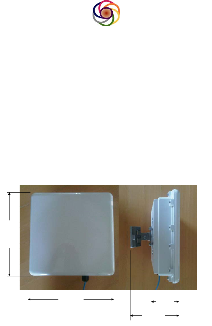
4.1 External Dimensions of the radio module
30.5 cm
30.5 cm
GWS3000 & GWS4000 External Dimensions
8.5 cm
17 cm
Figure 1: Diagram showing the external dimensions of the GWS-3000. The
mounting bracket shown is for the standard Wall Mount Configuration.
A picture of the GWS-3000 can be seen in the diagram above. The module
measures 30.5 cm in width, 30.5 cm in height. The thickness of the module is 8.5
cm from the front panel to the heat fins on the rear of the enclosure. If the mounting
@2013 6Harmonics Inc. All Right Reserved
8
bracket is attached the module has a total thickness of 17 cm from the front of the
module to the base of the wall mount bracket.
For a basic wall mount deployment, there is a clearance of 8.5 cm between the wall
and the heat fins of the module to allow for air circulation. When the radio is in
operation, the rear surface of the module can reach a temperature of Tambient + 20 oC.
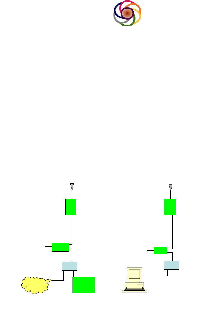
5. System Diagram
Below is a block diagram to show how the GWS radio can be used in a network.
Both the BTS and CPE can be powered via a POE Midspan. The mid-span accepts
AC power and is designed for international deployments with an input range of
100V-240V, 50-60 Hz. The mid-span then combines the Ethernet data along with a
DC bias voltage on the the Cat5e cable. The Ethernet cable from a personal
computer can be directly connected into the POE Midspan, or router as shown.
BTS CPE
iOMC
Router Router
UHF Airwaves
POE
Midspan
Internet
AC Power
POE
Midspan
AC Power
6. Software Environment
6.1 Overview
This User’s Manual is intended to provide guidance on what the Host
Software does and how to use the Host Software to make the GWS node
function properly.
The GWS-3000 Host Software provides the following functionalities:
a) Initialize host board and GWS-3000 radio;

@2013 6Harmonics Inc. All Right Reserved
9
b) Configure the host board and GWS-3000 radio
c) Provide interface for users to manage and operate host board and GWS-
3000 radio;
d) Control the behaviors of GWS node, .e.g. set GWS Node acts as BTS or
CPE
6.2 Node Initialization
After power up, the host software will load into RAM of host board from NAND,
start to initialize and setup all the devices in good working status, including:
initialize CPU and peripheral devices.
6.3 Setup and Communicate with Host Board
There are three ways to communicate with the Host Board: a) User Interface, b)
Serial Port and c) SSH Interface.
6.3.1 User Interfaces
The host software also provides different sets of user interface for users to
configure, manage and operate the host board or radio devices and the
commands are distinguished by user commands and debug commands. User
commands are intended to allow users to change configurable parameters to
manage the host board or radio, and the debug commands are intended for
the internal design/testing engineer to perform DVT or debug or set factory
parameters.
The User Interface is the general purpose interface which should be used by
the staff of the wireless operator to perform routine maintenance and
management functions on the nodes.
6.3.2 Serial Port
Use the terminal on a PC to Connect to Host board with the following parameters:
Parameters
Baud rate: 115200
Data bits: 8
Parity: None
Stop bits: 1
Flow control: None
Warning: This connection is for a professional installer which has been trained
by 6Harmonics and can damage the module if performed improperly. This
connection is used to burn the first image on the host board. The module is shipped
with the latest software pre-loaded and this procedure should not need to be
performed by the customer. Only in extremely rare circumstances, such as if the
flash becomes corrupted or a power failure occurs during a remote software upgrade,

@2013 6Harmonics Inc. All Right Reserved
10
will this procedure need to be performed. To perform the procedure the module
must be taken to a maintenance point and the lid must be opened to access the
serial connector on the host card.
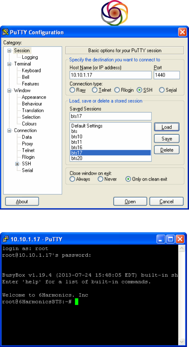
6.3.3 SSH
SSH will provide all debug commands to configure, manage and operate the
GWS Node
SSH Port 1440
USER: ********
PWD:********
Example:
Use putty on Windows XP to access the Node
Note: The SSH interface should only be used by qualified personnel
trained by 6Harmonics. Root access requires a User Name and Password
and is only available to 6Harmonics personnel or professional installers
which have been trained and certified by 6Harmonics. This guide is meant
for both non-certified users as well as professional installers which have
been trained and certified by 6Harmonics and as such we provide
instructions on how to use both the User Interface and the SSH interface.
@2013 6Harmonics Inc. All Right Reserved
11
@2013 6Harmonics Inc. All Right Reserved
12
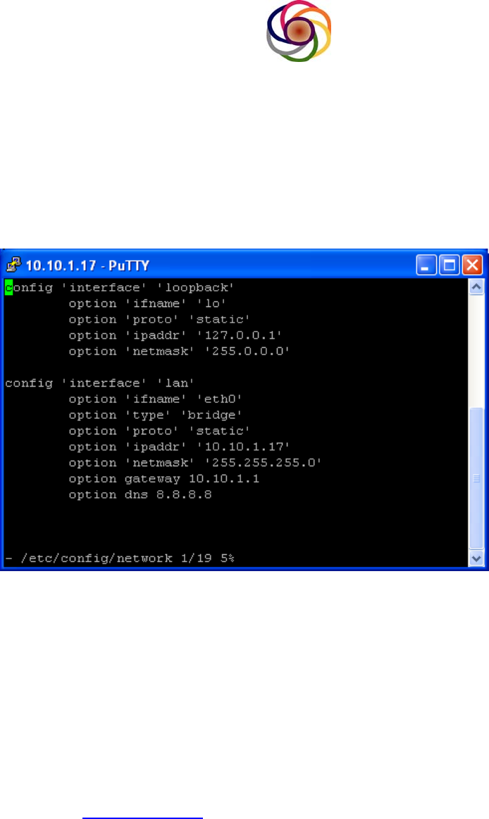
6.4 Configure the IP Address of the Nodes
When the modules are shipped from the factory they will all have the same IP
address, 192.168.1.1. Prior to deploying the modules, the installer should
reprogram the IP address to a value appropriate for the network in question. The IP
address can be rewritten by following the procedure below:
By default, the management IP ip address is 192.168.1.1
To change ip address, open /etc/config/network
Modify the ip address and gateway, save it.
Then type /etc/init.d/network restart.
6.5 Image burn and upgrade
6.5.1 Burn image for first time
Connect serial cable to host board, assume boot environment is ready ( image, tftp
server and http server are ready).
On terminal of PC, when prompt press any key. Press any key to access the bios
menu.
Choose boot over Ethernet. After boot success, in terminal, type
wget2nand http://xx.xx.xx.xx/ xx.xx.xx.xx is ip address of http server, and assume
all image are put in its root dir.
After downloaded the image, reboot the node and choose boot from NAND.
The default ip address for GWS node is 192.168.1.1
Default mode is BTS.
@2013 6Harmonics Inc. All Right Reserved
13
6.6.2 Upgrade Image
Assume boot environment is ready ( image, ftp server and http server are ready).
SSH the GWS Node. Type
firmwareupgrade http://xx.xx.xx.xx/
The GWS node will reboot after upgrade finished.
Attention: Currently, when upgrading the host image, all current configuration
will lost. The new image with default configuration will be used.
6.6.3 Upgrade the application
Assume upgrade environment is ready (application package and http server are
ready).
In SSH shell type
wget http://xx.xx.xx.xx/packagename.ipk
After download the application package.
In SSH Shell , type
opkg install applicationpackage.ipk
6.7 Configurations
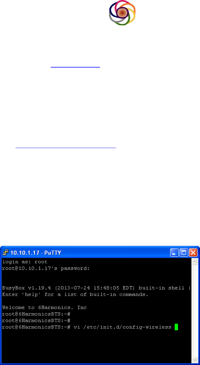
6.7.1 Configure GWS Node Mode as BTS or CPE
GW-3000 S Node can be configured as BTS or CPE. By default: GWS Mode is BTS
SSH to GWS Node, open /etc/init.d/config-wireless
@2013 6Harmonics Inc. All Right Reserved
14
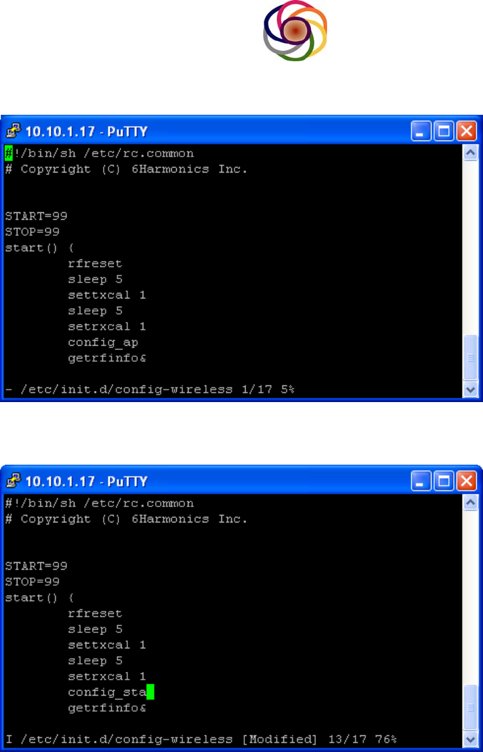
By default: GWS Mode is BTS, to set it to CPE mode, change config_ap to
config_sta
Save it, type re in SSH shell
@2013 6Harmonics Inc. All Right Reserved
15
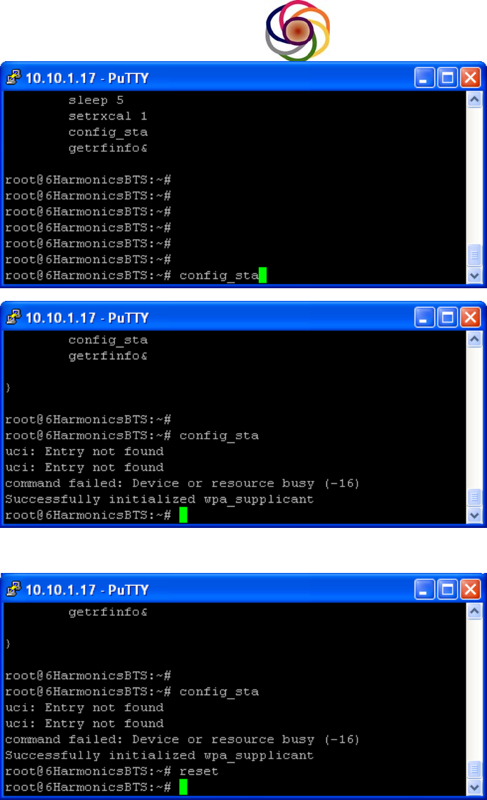
then type reset in SSH shell to reboot the GWS node
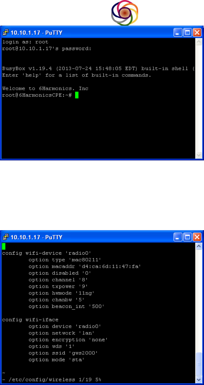
Now GWS Node is acting as CPE
@2013 6Harmonics Inc. All Right Reserved
16
To set CPE back to BTS, edit the /etc/init.d/config-wireless to change config_sta to
config_ap , save it, type config_ap in SSH shell then reset the GWS Node.
6.7.2 Wireless Configuration
There are two ways to modify the wireless configuration
1. For temporary change. (No reset needed)
Open /etc/config/wireless

@2013 6Harmonics Inc. All Right Reserved
17
Attention: Modifying the wireless settings are for debug purposes only and
you must be trained by 6Harmonics prior to attempting, otherwise you may
impair performance of the wireless link.
After performing the changes, save it in SSH Shell.
For the changes to take effect you must issue the following commands: a)
wifi down, and then b) wifi up. The new setting will be take effect but these are
not permanent. Once the GWS Node is reset, the changes will be gone and
the default configuration will be loaded from the file.
2. For permanent changes
Open /sbin/config_ap for BTS or /sbin/config_sta for CPE
Attention: Modifying the wireless settings are for debug purposes only and you must be trained by
6Harmonics prior to attempting, otherwise you may impair performance of the wireless link.

@2013 6Harmonics Inc. All Right Reserved
18
After changes, save it, then reset.
6.7.3 Radio turn on (For non database application)
The default setting radio is off. To turn on the radio with out database access, in
SSH Shell
Type txresume, the radio will be enabled.
Note: This functionality is only available for units shipped to countries which do not
use a White Space Database. For US customers this capability is not provided.
6.7.4 Check channel number (For non database application)
For non database application, after the radio has been enable, expect the
connection is up at this time. If not, please check if BTS and CPE are configured to
the same channel.
7.0 User Commands
As stated previously, users commands are a set of commands for users to configure the radio and get
information from the radio. The supported commands are listed in table 1 and can be exercised by telnetting to
the node.
Table 1. General User Commands
Commands Description
setchan Set Channel Number
getchan Show Channel Number
setagcmode Set AGC mode
getagcmode Show AGC mode
rfinfo Show RF informations
u Tx power up 0.5dBm
c Tx power down 0.5 dBm
cu Tx power up 5 dBm
cd Tx power down 5dBm
settxpwr Set Tx Power
gettxpwr Show current Tx power
monitor Show Node status
setinstaller Set installer
getinstaller Show information about who install the node
getchanlist Show channel list
getsubchanlist Show sub channel list
txoff Turn off Tx
txresume Resume the Tx
gettxstatus Show tx status
getrxstatus Show rx status
setchanlist Set channel list
setsubchanlist Set Sub Channel list
setrxgain Set Rx Gain
getrxgain Show Rx Gain
@2013 6Harmonics Inc. All Right Reserved
19
reboot Reboot the GWS node
--help Help command to list all above commands
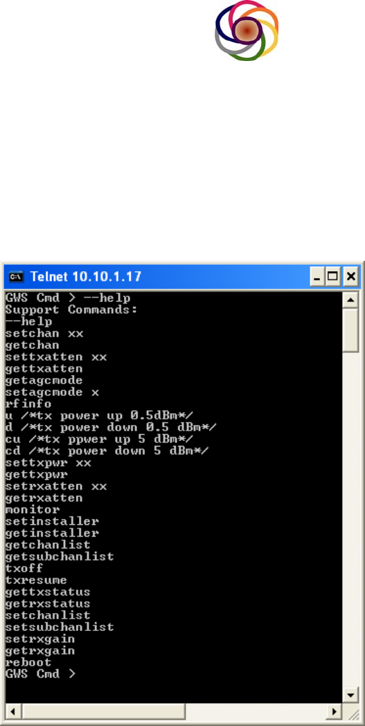
7.1 help command
This command lists all available commands. If you type help during the telnet
session, you’ll see the followings:
7.2 setchan command
The “setchan” command is to set what channel the radio is going to work on.
The channel number range will vary from region to region. For example for
US, the number would be 14~51, except channel 36, 37 and 38. For
operation in the US, the module needs to querry the available channel from
FCC database and the SW will only allow the module to tune to a channel
which is part of the channel list received from the data base.
GWS Cmd >setchan 35

@2013 6Harmonics Inc. All Right Reserved
20
7.3 getchan command
The “getchan” command returns the current channel setting. The following
returns that the current channel is set to channel 33:
GWS Cmd >getchan
Channel: 33
7.4 txresume command
The “txresuem” command is to resume radio tx chain, otherwise tx will not
transmitting. The syntax would be:
GWS Cmd >txresume
7.5 txoff command
The command “txoff” is to turn tx chain off and cease transmission:
GWS Cmd >txoff
7.6 gettxstatus command
To know what tx status is and what tx parameters are set to, you can use
“gettxstatus” command:
GWS Cmd >gettxstatus
TX : OFF
Tx_Atten : 10
TV Channel : 41
CurTxPower : 20.0 dbm
MaxTxPower : 20.0 dbm
MinTxPower : -6.5 dbm
TX Power Cal: ON
GWS Cmd >
7.7 getrxstatus command
The “rxstatus” command will return the current RX status:
GWS Cmd > getrxstatus
RX : ON
AGC Mode : 2
RF IFOUT : IFOUT2
Rx_F_Atten : 0
Rx_R_Atten : 22
RX Gain : 12.0 dB
RX Gain Cal : ON
GWS Cmd >
7.8 settxpwr command
The “settxpwr” command allows the user to set the tx power in 0.5dbm steps.
The following is to set the tx power to 11.5dbm:
GWS Cmd >settxpwr 11.5
GWS Cmd >

@2013 6Harmonics Inc. All Right Reserved
21
Note1: The Software will only allow the user to increase the maximum power
up to the maximum permissible power.
Note2: If manual power control has been implemented, the user should refer
to the section in the document which details the power control procedure to
ensure the link is configured properly.
7.9 gettxpwr command
The “gettxpwr” command will return the current tx power setting in dbm:
GWS Cmd >gettxpwr
CurTxPower: 11.5 dbm
GWS Cmd >
7.10 rfinfo command
The “rfinfo” command will return the current radio configuration:
GWS Cmd >rfinfo
6 Harmonics GWS-1100 - Rev 04
Firmware #601100-410 Generated at: Jul 9 2013 16:25:19.
Radio SNO : 19
TX : DOWN
RX : DOWN
Region : 0
Channel : 41
CurTxPower : 20.0 dbm
MaxTxPower : 20.0 dbm
MinTxPower : -6.5 dbm
RX Gain : 12.0 dbm
Temperature : 38.0 C
GWS Cmd >
7.11 u command
The “u” command will set tx power up 0.5dBm:
GWS Cmd >u
7.12 d command
The “d” command will set tx power up 0.5dBm:
GWS Cmd >d
Note: The “u” and “d” commands are used to perform manual power control
and load balancing to optimize network performance. The can be used to
increase or decrease transmit power during while the node is in service and
carrying traffic.

@2013 6Harmonics Inc. All Right Reserved
22
7.13 setchanlist command
The “setchanlist” is to set channel list. The following is to set channel list 14
15 35:
GWS Cmd > setchanlist 14 15 35
GWS Cmd >
Note1: For markets such as the USA, where the regulatory rules require the
node to access a database, the radio will only accept a channel list from an
approved database with whom it has registered.
Note 2: This command is intended for countries where a database is not
prescribed and allows the user to program the allocated channels into
memory. In this way, the node can only be tuned to a channel which is part
of the channel list, which will accelerate handoff and the scanning process
and will ensure that node does not attempt to transmit on a channel which is
not permitted. The software will only attempt to establish communication links
on a channel which is part of the “channel list” and the user will only be
permitted to change the channel, to a channel which is part of the “channel
list.”
7.14 getchanlist command
The “getchanlist” will return the current channel list stored in memory:
GWS Cmd > getchanlist
GWS Cmd >
14
15
35
If the radio has received the channel list from a white space database, then
this command can be used by the operator to determine which channels are
available. The command does not querry the database but produces the
channel list which was last provided by the database to be displayed.
7.15 getrxgain command
getrxgain to return the current rx gain in dbm:
GWS Cmd >getrxgain
Note: The rxgain which is reported is the gain of the White Space radio front
end, and does not include the baseband gain. The system provides
reasonably good performance with an rxgain of 12 dB. For short links where
RX sensitivity is not critical, the gain can be reduced accordingly. The
receive chain includes two attenuators, “rxatten0” and “rxatten1”.
“rxatten0” is situated after the LNA but before the downconverter and for
maximum sensitivity should be left at a value of 0. “rxatten1” is located at IF
@2013 6Harmonics Inc. All Right Reserved
23
and can be used to trim the RX gain up or down by a few dB without
adversely affecting sensitivity.
7.16 setrxgain command
The “setrxgain” command is to set rx gain.
GWS Cmd >setrxgain 10
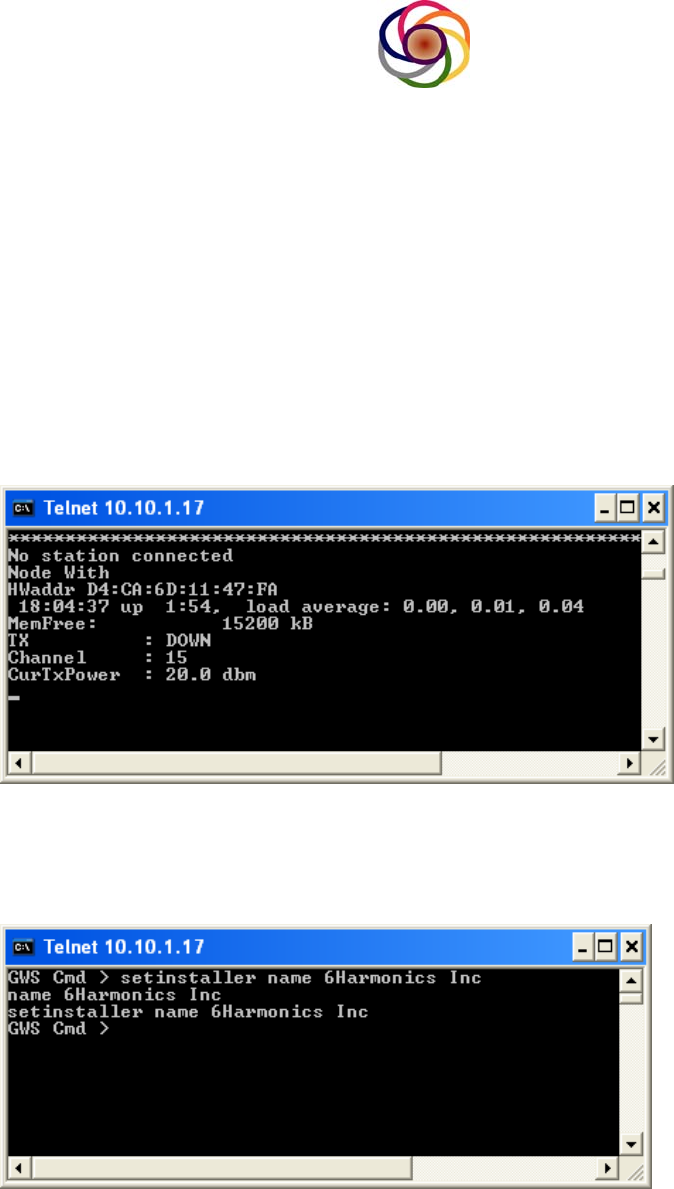
7.17 monitor command
The “monitor” command is to start program to monitor status of Node. Typing
“monitor” in the telnet window will initial the program which allows the status of the
radio link to be monitored real time. Below is an example of the parameters which
are displayed.
GWS Cmd>monitor
7.18 setinstaller command
The “setinstaller” command is to record who installed the GWS Node. For US
customers this field is made available to the White Space database and the node
will not be allowed to connect to the database unless there is a valid entry.
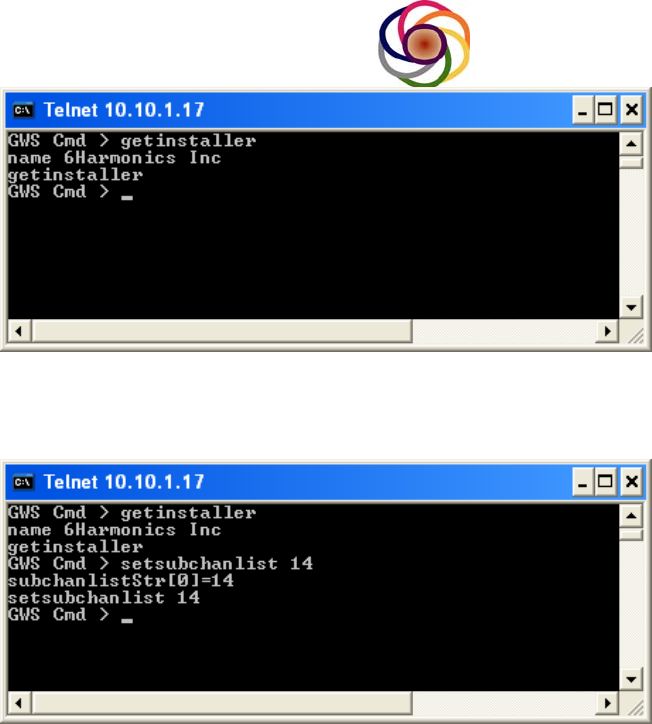
7.19 getinstaller command
The “getinstaller” shows who installed the GWS Node
@2013 6Harmonics Inc. All Right Reserved
24
7.20 setsubchanlist command
The “setsubchanlist” command is to set sub channel list
There is an important distinction between the “setchanlist” and the “setsubchanlist”
which we will explain here. The “chanlist” can be programmed and read using the
“setchanlist” and “getchanlist” commands and these are the channels on which the
node is permitted to transmit. This list will be provided by the White Space
Database in countries such as the US, and in countries which do not use a
database it will be dependent on local regulatory rules or the license an operator
may have in place and must be programmed by the professional installer. For US
customers the software will not allow the user to manually program the channel list.
The “subchanlist” does not come from the database but is meant to further restrict
the channels which are used based on the hardware configuration. A situation
where the user may want to reduce the number of channels would be if a Combiner
or Narrow Band Filter is placed between the radio module and the antenna. For
example, if the passband of a filter covers Channels 14 to 22, the user would use
the following command”
Setsubchanlist 14 15 16 17 18 19 20 21 22
The software will then know that the node can only transmit on a channel between
14 and 22, inclusive.
@2013 6Harmonics Inc. All Right Reserved
25
The actual channel which is used must be part of both the “chanlist” and the
“subchanlist”. The “chanlist” is from the database while the “subchanlist” is from
the installer and used to configure hardware limitations such as a narrow band filter
which is inline with the antenna. The Software will only attempt to use a channel
which are part of both lists.
By default, the “subchanlist” includes all channels for a given market. For the USA
this would be channels 14-35, and 39-51. To restrict this further the professional
installer must rewrite the subchanlist.
Ensuring that the “subchanlist” is properly programmed will improve network
performance by ensuring nodes do not try to transmit at frequencies for which an in-
line filter or combiner might be attenuating the signal.
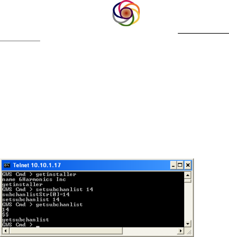
7.21 getsubchanlist command
The “getsubchanlist “ is used to read the sub channel list
7.22 cu command
The “cu” command is to set tx power up 5 dBm
7.23 cd command
The “cd” command is to set tx power down 5 dBm
Note: The “Cu” and “cd” commands are to perform course power adjustments in the
field and can be used to adjust transmit power while a node is in service. The
software will only allow the user to increase the power up to the limit allowed by the
regulatory standard in a given market. For the GWS-3000 in the US, this is 20
dBm.
7.24 setagcmode command
The “setagcmode” is to set the Receiver AGC mode. The choices are 0, 1,
and 2.
GWS Cmd >setagcmdoe 2

@2013 6Harmonics Inc. All Right Reserved
26
GWS Cmd >
The choices are:
0 is fixed mode,
1 is maximum attack mode,
2 is minimum attack mode.
The standard deployment and default configuration is to use AGC mode 2.
For deployments where the node is subjected to very harsh interference, the user
can use the “setagc” command to try to improve the throughput on the link. In
general, AGCmode2 will provide the best protection from IM3 products which fall in
channel. As such, if there are two or more interfering carriers which result in an
Intermodulation Product falling in channel, AGC mode 2 will give the best
performance.
If however the interference comes primarily from a single carrier which results
in Gain Drop and hence a loss of RX sensitivity, the user might get slightly better
performance by increasing the attack point of the AGC by using the “setagcmode 1”
command, or even turning off the AGC completely using the “setagcmode 0”
command.
The receiver of the GWS-3000 has been designed to sustain fairly high levels
of interference and for the vast majority of deployments leaving the radio in
“agcmode 2” (the default configuration) will provide good results. This information
is purely to give our customers some insight and help them optimize network
performance in the even that a node is subjected to very strong interference.
Another approach to reduce severe interference is to decrease the front end RX
attenuator by using the “setrxatten” command. Please see Section 7.26 for more
details.
7.25 getagcmode command
The “getagcmode” command will return the current agc mode setting:
GWS Cmd >getagcmode
AGC Mode : 2
GWS Cmd >
7.26 setrxatten command
The “setrxatten” command is to set the attenuation values for two of the RX
attenuators, the syntax is: setrxatten x n; here x means attenuator (0 means
front attenuator, 1 means rear attenuator).
To set front attenuator:
GWS Cmd >setrxatten 0 10
GWS Cmd >
To set rear attenuator:

@2013 6Harmonics Inc. All Right Reserved
27
GWS Cmd >setrxatten 1 30
GWS Cmd >
The attenuator values will be set at the factory to provide the best combination of
RX Sensitivity and RX Linearity. The first attenuator is located between the LNA
and downconverter and is therefore at RF. In general this attenuator will be set to its
minimum attenuation “setrxatten 0 0”. The second attenuator is at the IF frequency
and is located after the channel select filter. The second attenuator is typically used
to trim the gain up or down in the factory to adjust for part to part variation during the
fabrication process. The gain of the GWS receiver is carefully set to allow the best
combination of RX linearity and sensitivity and is factored into the calculation of
RSSI.
In rare cases the user may find it beneficial to adjust the attenuator values. For
short links where the radio does not need to receive near its sensitivity, or which are
susceptible to strong interference, the user may find the radio performs better if the
first attenuator value is increased slightly, since this will reduce the amount of
interference incident upon the demodulator.
7.27 getrxatten command
The “getrxatten” command will return current setting for both attenuators:
GWS Cmd >getrxatten
FRxAtten : 10
RRxAtten : 30
GWS Cmd >
7.28 reboot command
The “reboot” command is to reboot GWS Node
GWS Cmd>reboot
8 Power Control and Link Configuration
For certain jurisdictions such as the USA the FCC has mandated that a TV Band
Device must use the minimum amount of power necessary in order to successfully
establish/maintain the communication link. In other jurisdictions there may not be a
requirement yet, but implementing good power control at the network level is
nevertheless recommended to minimize interference between nodes and to optimize
the aggregate throughput at the network.
8.1 Manual Power Control
For small networks the user may prefer to perform the power control manually to
have a good control over the interference and to balance the load between links.

@2013 6Harmonics Inc. All Right Reserved
28
Below is a description of how to perform power control manually using the GWS-
3000 user interface. 6Harmonics is currently developing a SON algorithm which will
perform power control at the network level. This algorithm is not yet released but
should become available sometime late in 2013 or early 2014.
8.1.1 Point to Point Link
For a point to point link, one BTS connected to a single CPE, we will adjust the
power of both the uplink and downlink to have an RSSI (Received Signal Strength)
of about -75 dBm at both nodes. To operate at our highest modulations, 64 QAM
5/6 encoding, we require a CINR of about 24 dB. For a 5 MHz modulation
bandwidth, kTBf = -107 dBm/5MHz. The noise figure of the radio is 5.0 dB and
hence the noise floor of the radio referred to the antenna port is -102 dBm/5MHz.
To maintain an SNR of 24 dB, the RSSI must be at -78 dBm/5 MHz carrier. An extra
3 dB is provided as margin and hence the recommended receive signal strangeth is
-75 dBm.
In certain deployments the noise floor of the channel may be higher than thermal
noise, due to interference power from nearby transmitters which are co-channel or
even adjacent or alternate channel to the link being configured. 6Harmonics has
surveyed the noise floor of UHF channels is several US and Canadian cities and
some channels are very clean with an integrated noise power near -102 dBm/5MHz
but many channels have an noise floor which is 3-6 dB above ktBf. If the RSSI is
at -75 dBm but the MCS is low, not consistently shown as MCS6 or 7, then the
power may need to be increased by a few dB until a satisfactory MCS is achieved.
8.1.1.1 Configure the link:
• Telnet into the BTS and CPE.
• From the telnet session type “monitor”
o The monitor session will show you the RSSI as well as the MCS for
both the BTS and CPE.
• Adjust the Uplink TX Power of the CPE.
o Telnet to the CPE
o If the RSSI at the BTS is below or above, – 75 dBm, increase or
decrease the CPE TX Power by using the following commands:
U Æ Increases power by 0.5 dB (fine adjustment)
C Æ Decreases TX power by 0.5 dB (fine adjustment)
Cu Æ Increases power by 5 dB (course adjustment)
Cd Æ Decreases TX power by 5 dB (course adjustment)
o Between each adjustment observe the RSSI and MCS value at the
BTS RX until the desired value is achieved.
• Adjust the Downlink TX Power of the BTS
o Telnet to the BTS
o If the RSSI at the BTS is below or above – 75 dBm, increase or
decrease the CPE TX Power by using the following commands:

@2013 6Harmonics Inc. All Right Reserved
29
U Æ Increases power by 0.5 dB (fine adjustment)
C Æ Decreases TX power by 0.5 dB (fine adjustment)
Cu Æ Increases power by 5 dB (course adjustment)
Cd Æ Decreases TX power by 5 dB (course adjustment)
o Between each adjustment observe the RSSI and MCS value at the
CPE RX until the desired value is achieved.
o The following commands can be used to read the transmitter
configuration:
Gettxstatus : Will show the TX power as well as the value of the
TXattenuator. The TX attenuator cannot be accessed using the
User Interface but is provided for diagnostic purposes.
\ Note: If the User tries to increase the TX power beyond the maximum power
for which the device has been certified, the software will not allow the TX
power to be increased beyond the maximum permissible value.
Furthermore, for some links it may not be possible to achieve an RSSI of -75
dBm, at which point the link should be set to transmit at the maximum
permissible power to get the best RSSI and hence SNR.
8.1.2 Point to Multi-Point Link
The power control for a point to multi-point link can be performed in a similar manner
with a few small but important differences. The Uplink power control should be
performed first to ensure that signals from the 2 or more CPE’s arrives at the BTS
at a similar power. This will prevent the creation of a near far issue for the BTS
which can severely degrade throughput. For the Downlink power control, the BTS
TX power should be decreased until the CPE with the weakest signal has an RSSI of
about -75 dBm. If the furthest CPE cannot achieve an RSSI of -75 dBm when the
BTS is transmitting at full power, then the BTS should be configured at full power in
order to provide a reasonable level of service to the furthest CPE.
It is important to ensure we do not have a very large spread of RSSI’s on the uplink,
from the multiple CPE’s. Acceptable values are from Senstivity ( -100 dBm to about
-70 dBm). The presence of a strong signal , > -60 dBm will actuate the RX AGC of
the BTS and will degrade the quality of the connection for CPE’s which are arriving
at low powers near sensitivity. If the Uplink power control is performed properly, the
signals from all CPE’s should be between -100 dBm and -70 dBm and no near far
issue will be present. Ideally, the signal from all CPE’s should be received by the
BTS at about -75 dBm.
8.1.2.1 Configure the link:
• Telnet into the BTS and each of the CPE’s.
• From the telnet session type “monitor”

@2013 6Harmonics Inc. All Right Reserved
30
o The monitor session will show you the RSSI as well as the MCS for
both the BTS and CPE’s.
• Adjust the Uplink TX Power for each of the CPE’s in sequence.
o Telnet to the CPE
o If the RSSI at the BTS is above or below – 75 dBm, increase the CPE
TX Power by using the following commands:
U Æ Increases power by 0.5 dB (fine adjustment)
C Æ Decreases TX power by 0.5 dB (fine adjustment)
Cu Æ Increases power by 5 dB (course adjustment)
Cd Æ Decreases TX power by 5 dB (course adjustment)
o Between each adjustment observe the RSSI and MCS value at the
BTS RX until the desired value is achieved.
o Repeat for the Next CPE.
• Next, adjust the Downlink TX Power of the BTS
o The BTS will transmit at a constant power to all CPE’s. As such, the
BTS TX Power should be reduced only as much as is allowed to
provide an acceptable signal level to the furthest CPE, or CPE with the
weakest RSSI. Some CPE’s which may be closer to the BTS will
receive the downlink signal at a power greater than -75 dBm. This is
not an issue. The AGC in the CPE is capable of receiving the downlink
signal from near -100 dBm to as high as -15 dBm.
o Telnet to the BTS
o If the RSSI at the furthest CPE is below or above – 75 dBm, increase
or decrease the BTS TX Power by using the following commands:
U Æ Increases power by 0.5 dB (fine adjustment)
C Æ Decreases TX power by 0.5 dB (fine adjustment)
Cu Æ Increases power by 5 dB (course adjustment)
Cd Æ Decreases TX power by 5 dB (course adjustment)
o Between each adjustment observe the RSSI and MCS value at the
CPE RX until the desired value is achieved.
• Before finalizing the setup, observe the RSSI and MCS for each of the links.
The RSSI for the furthest CPE should be at about -75 dBm or lower. Other
CPE’s should have a higher RSSI. For Uplink signals, all CPE’s should be at
about -75 dBm, or lower for long links where the CPE is transmitting at full
power.
Note: If the User tries to increase the TX power beyond the maximum power
for which the device has been certified, the software will not allow the TX
power to be increased beyond the maximum permissible value.
Furthermore, for some links it may not be possible to achieve an RSSI of -75
dBm, at which point the link should be set to transmit at the maximum
permissible power to get the best RSSI and hence SNR.

@2013 6Harmonics Inc. All Right Reserved
31
8.2 Automatic Power Control
6Harmonics is in the process of developing and testing an automatic power control
algorithm. This capability will be important for larger deployments and will be
introduced later in 2013. The feature is not yet available.
END OF DOCUMENT