7signal ABGN-EYE-APU3 7Signal Sapphire User Manual Carat User Guide
7signal 7Signal Sapphire Carat User Guide
7signal >
Contents
- 1. user manual 1
- 2. user manual 2
- 3. user manual 3
- 4. user manaul 1
user manaul 1

7signal Ltd, Panuntie 6, FI-00620 HELSINKI, FINLAND, +358 40 777 7611, info@7signal.com, www.7signal.com
7signal Sapphire Carat
Carat User Guide
Release 3.1
Preface i
7signal Ltd, Panuntie 6, FI-00620 HELSINKI, FINLAND, +358 40 777 7611, info@7signal.com, www.7signal.com
7signal Sapphire Carat Carat User Guide Release 3.1
PREFACE
Document scope
This document is aimed for people that shall manage and configure 7signal Sapphire quality
tests on wlan networks. The test pattern configuration and 7signal Sapphire system
administration are explained in this document.
This document does not describe how the software is installed and how to handle the
monitoring station. This is found in 7signal Sapphire Deployment Guide. To get guidance on
how to interpret the measurements, please turn to 7signal Sapphire Loupe User Guide.
FCC Warning
The radiated output power of the 7signal Sapphire Eye complies with the FCC RF exposure
limits. To avoid the possibility of exceeding the FCC radio frequency exposure limits, a distance
of at least 20 cm should be kept with the user and the device while operating.
The FCC ID for 7signal Sapphire Eye is YLF-2010-08-APU2 for
IEEE802.11a/b/g
FCC APPROVAL PENDING ON RELEASE DATE
The FCC ID for 7signal Sapphire Eye is YLF-EYE-ABGN-APU3 for
IEEE802.11a/b/g/n
This device is restricted to indoor-only use in 5150.0-5250.0 MHz and
5470.0 -5725.0 MHz bands
Note to the user
Any uninstructed modification to the 7signal products may result in violation of FCC
requirements.

Preface ii
7signal Ltd, Panuntie 6, FI-00620 HELSINKI, FINLAND, +358 40 777 7611, info@7signal.com, www.7signal.com
7signal Sapphire Carat Carat User Guide Release 3.1
Contact information
Contact us at 7signal
by mail: Panuntie 6, FI-00620 Helsinki, Finland
by email: info@7signal.com
by phone: +358 40 777 7611 (exchange)
report defects by email: defect-report@7signal.com
any other request: support@7signal.com

Table of Contents iii
7signal Ltd, Panuntie 6, FI-00620 HELSINKI, FINLAND, +358 40 777 7611, info@7signal.com, www.7signal.com
7signal Sapphire Carat Carat User Guide Release 3.1
TABLE OF CONTENTS
1 7signal sapphire – WQA Solution .......................................................................................1
1.1 System overview ............................................................................................................. 2
2 Sapphire Eye .....................................................................................................................3
3 Sapphire Carat ..................................................................................................................5
4 Sonar ................................................................................................................................6
5 Sapphire Loupe .................................................................................................................7
6 Carat user Interface ..........................................................................................................8
6.1 Menus ............................................................................................................................. 8
6.1.1 Navigation ............................................................................................................ 8
6.2 Network Topology ........................................................................................................... 9
7 Starting the Carat configuration ...................................................................................... 11
7.1 How To Create The Minimum Set Of Users .................................................................. 11
7.2 Automated Tests ........................................................................................................... 12
7.3 Access Rights ................................................................................................................. 12
8 User Management .......................................................................................................... 13
8.1 User Groups And Object Permissions ........................................................................... 13
8.2 User Group Hierarchy ................................................................................................... 13
8.3 User Access Levels ......................................................................................................... 14
8.4 User Group And User Management ............................................................................. 14
8.5 User Groups .................................................................................................................. 14
8.5.1 Related icons ...................................................................................................... 14
8.5.2 User Group Parameters ..................................................................................... 14
8.5.3 Adding User Groups ........................................................................................... 15
8.5.4 Editing User Groups ........................................................................................... 15
8.5.5 Removing User Groups ...................................................................................... 15
8.5.6 User Group Status .............................................................................................. 16
8.6 Users ............................................................................................................................. 16
8.6.1 Related icons ...................................................................................................... 16
Parameters .................................................................................................................. 16
8.6.2 Adding Users (New) ........................................................................................... 16

Table of Contents iv
7signal Ltd, Panuntie 6, FI-00620 HELSINKI, FINLAND, +358 40 777 7611, info@7signal.com, www.7signal.com
7signal Sapphire Carat Carat User Guide Release 3.1
8.6.3 Adding Users By Copying ................................................................................... 17
8.6.4 Editing User Information ................................................................................... 17
8.6.5 Removing Users ................................................................................................. 18
8.6.6 Changing Password For Users ............................................................................ 18
9 Network topology configuration...................................................................................... 19
9.1 Choosing Networks To Be Monitored ........................................................................... 19
9.1.1 Organization....................................................................................................... 19
9.1.2 Addition Network Locations .............................................................................. 20
9.1.3 Hidden Networks ............................................................................................... 21
9.1.4 Removing Networks ........................................................................................... 21
9.1.5 Channel Configuration ...................................................................................... 22
10 Eye configuration .......................................................................................................... 24
10.1 States of Monitoring Stations ..................................................................................... 24
10.1.1 Adding Monitoring Stations ............................................................................. 24
10.1.2 Monitoring Station Settings ............................................................................. 25
10.1.3 Activating Monitoring Stations ........................................................................ 26
10.1.4 Updating Monitoring Station Software ........................................................... 26
10.2 Initial network scan ..................................................................................................... 27
11 Creation And Use Of Encryption Keys............................................................................. 29
11.1 Supported Encryption Types ....................................................................................... 30
11.2 Adding Encryption Keys (PSK) ..................................................................................... 31
11.2.1 Passphrase and pre-shared key ....................................................................... 31
11.2.2 Adding .............................................................................................................. 31
11.3 On Certificate-Based Encryption ................................................................................. 31
11.4 Multiple Keys Per Eye .................................................................................................. 32
11.4.1 Microsoft PKI Infrastructure ............................................................................ 32
12 Test End-Points ............................................................................................................. 34
12.1 Sonar ........................................................................................................................... 34
12.2 Generic Test Counterparts .......................................................................................... 34
13 Access Point Information ............................................................................................... 36
13.1 Replacing Access Points .............................................................................................. 36
14 Links And Link Groups ................................................................................................... 38
14.1 Forming Links .............................................................................................................. 38

Table of Contents v
7signal Ltd, Panuntie 6, FI-00620 HELSINKI, FINLAND, +358 40 777 7611, info@7signal.com, www.7signal.com
7signal Sapphire Carat Carat User Guide Release 3.1
14.2 Removing Links ........................................................................................................... 38
14.3 Creating Link Groups ................................................................................................... 39
14.4 Removing Link Groups ................................................................................................ 39
14.5 Adding Link To Group .................................................................................................. 39
14.6 Removing Links From Group ....................................................................................... 39
15 Alarms .......................................................................................................................... 40
15.1 Creating Alarm Groups ................................................................................................ 40
15.2 Binding Alarm Groups To Access Points ..................................................................... 41
15.3 Alarm Messages .......................................................................................................... 42
15.4 Alarm Forwarding ....................................................................................................... 42
15.4.1 Email Forwarding ............................................................................................. 42
15.4.2 SNMP ............................................................................................................... 43
16 Traffic Classes ............................................................................................................... 45
17 Automated test configuration ....................................................................................... 46
17.1 Test Profiles ................................................................................................................. 46
17.2 Contents Of A Test Profile ........................................................................................... 47
17.2.1 Passive ............................................................................................................. 47
17.2.2 Warehouse ....................................................................................................... 47
17.2.3 Office ................................................................................................................ 48
17.2.4 Lightweight ...................................................................................................... 48
17.2.5 VoIP .................................................................................................................. 48
17.2.6 Hospital ............................................................................................................ 48
17.2.7 Spectrum and Noise ......................................................................................... 48
17.2.8 Surveillance ...................................................................................................... 48
17.2.9 TripleSSID ......................................................................................................... 48
17.3 Testing multiple wlan networks in one test profile .................................................... 48
17.4 Operations on Templates ............................................................................................ 49
17.4.1 Duplicate .......................................................................................................... 49
17.4.2 Copy as essid .................................................................................................... 49
17.5 Operation on Test Element ......................................................................................... 49
17.5.1 Copy element ................................................................................................... 49
17.6 Operations on Test Profile Node................................................................................. 50
17.7 Operations on Test Profile .......................................................................................... 50
17.8 Operations on essid inside a test profile .................................................................... 51
17.9 On test elements ......................................................................................................... 51

Table of Contents vi
7signal Ltd, Panuntie 6, FI-00620 HELSINKI, FINLAND, +358 40 777 7611, info@7signal.com, www.7signal.com
7signal Sapphire Carat Carat User Guide Release 3.1
17.9.1 Modifying test parameters .............................................................................. 51
17.9.2 Use case: Multiple SSID testing ....................................................................... 52
17.10 Running test profiles ................................................................................................. 53
18 Manual tests ................................................................................................................. 54
18.1 “Network Scan” test .................................................................................................... 54
18.2 “Client scan” test ......................................................................................................... 55
18.2.1 Addition of a new client ................................................................................... 57
18.3 Spectrum Analyzer ...................................................................................................... 58
18.4 “Noise monitor” test ................................................................................................... 58
18.5 “Client Traffic Test” ..................................................................................................... 59
18.6 “Air Utilization” test .................................................................................................... 60
18.7 “Optimal Antenna Selection” test ............................................................................... 61
18.8 Download Tests ........................................................................................................... 62
18.9 Upload Tests ................................................................................................................ 63
18.10 “Ping” test ................................................................................................................. 64
18.11 Traceroute Test ......................................................................................................... 65
18.12 “Access point traffic” test ......................................................................................... 66
18.13 “MOS test” ................................................................................................................ 67
18.13.1 MOS test parameters ..................................................................................... 68
18.13.2 MOS Test Result ............................................................................................. 68
18.14 “HTTP URL test” ........................................................................................................ 69
18.15 “Internet AvailabilityTest” ........................................................................................ 70
18.16 “SIP Register Test” .................................................................................................... 71
19 Service Level Agreement ............................................................................................... 74
19.1 Defining a Service Level Agreement into the system ................................................. 74
19.2 Defining SLA Key Performance Indicators (KPI) .......................................................... 74
19.3 Example: Upload throughput KPI ................................................................................ 75
19.4 Creating an SLA group ................................................................................................. 75
19.4.1 Creating an SLA group from a template .......................................................... 75
19.4.2 Creating an SLA group from scratch ................................................................ 76
19.4.3 Binding an SLA group to a Link ........................................................................ 76
19.4.4 Binding an SLA group to a link group ............................................................... 77
19.4.5 Binding an SLA Group to other Entities ........................................................... 77
19.4.6 SLA propagation hierarchy ............................................................................... 77
20 Continuos And Automated Reporting ............................................................................ 78

Table of Contents vii
7signal Ltd, Panuntie 6, FI-00620 HELSINKI, FINLAND, +358 40 777 7611, info@7signal.com, www.7signal.com
7signal Sapphire Carat Carat User Guide Release 3.1
20.1 Subscription for a new report ..................................................................................... 78
20.2 Adding Report Items ................................................................................................... 79
20.2.1 Adding SLA compliance report item ................................................................ 80
20.2.2 Adding KPI report item .................................................................................... 81
20.2.3 Adding SLA report item .................................................................................... 83
20.2.4 Adding alarm report item ................................................................................ 84
21 Viewer Software ........................................................................................................... 85
22 Email Servers ................................................................................................................ 86
23 Database Backup .......................................................................................................... 87
23.1 Backup options ............................................................................................................ 87
23.1.1 Automated backup with server downtime ...................................................... 87
23.1.2 Automated backup without server downtime ................................................ 87
23.1.3 Manual backup ................................................................................................ 87
23.2 Database logging ......................................................................................................... 88
23.2.1 Purging database logs ...................................................................................... 88
23.3 Backup method options .............................................................................................. 89
23.3.1 Default state (not recommemded) .................................................................. 89
23.3.2 First degree of backup: offline backup ............................................................ 89
23.3.3 2nd degree of backup: online backup ............................................................. 90
23.3.4 Changing log settings ....................................................................................... 91
23.3.5 Managing backup levels................................................................................... 91
23.3.6 File system settings for the database .............................................................. 91
23.3.7 Changing backup settings ................................................................................ 91
23.4 Restoring backups ....................................................................................................... 92
24 Nagios Support ............................................................................................................. 93
24.1 Adding Sapphire Host Information To Nagios Server ................................................. 93
24.2 Adding Nagios Plug-ins To Sapphire Software ............................................................ 94
24.2.1 Install NRPE daemon ........................................................................................ 94
24.2.2 Install toolset ‘Nagios plugins’ ......................................................................... 94
24.3 Verifying Nagios Installation ....................................................................................... 94
24.4 Removing Nagios plugins ............................................................................................ 94

1 7signal sapphire – WQA Solution 1
7signal Ltd, Panuntie 6, FI-00620 HELSINKI, FINLAND, +358 40 777 7611, info@7signal.com, www.7signal.com
7signal Sapphire Carat Carat User Guide Release 3.1
1 7signal sapphire – WQA Solution
Welcome to learn about 7signal Sapphire, that provides you a new way to continuously and
automatically measure the health and quality of a wireless network from the user's
perspective. A commonly used term here is wireless quality assurance, or WQA. Companies
and their business processes are becoming increasingly dependent on the performance and
service quality of their wireless networks. Thanks to the Sapphire WQA solution, companies
can integrate the quality management of wireless networks with their existing IT and
communications technology services.
7signal Sapphire uses monitoring stations (Sapphire Eye) to monitor performance and quality
in WLAN cells and to monitor the surrounding radio frequency environment. The performance
of the customer’s network is tested against a test server (Sonar). Interactive tests, monitoring
stations, and parameters for automatic measurement are managed with a centralized
management tool (Sapphire Carat). The measurement results are reported via a reporting
application (Sapphire Loupe).
The monitoring station, Sapphire Eye, continuously monitors the selected WLAN channels via
passive listening, which does not have an impact on network performance. It can also emulate
a client device in the target network and then use the network and the services provided
through it. By analyzing the measurement results, the solution can detect network
performance and quality-of-service (QoS).The solution can also produce proactive statistics on
the predicted user experience of network performance, which enables the company to
increase network capacity before the users notice loss of performance.
In user emulation tests, also known as active tests, Eye connects to the test server (Sonar) over
the wireless network and uses it like an ordinary production service. The use may include mass
file transfers, browser downloads, wireless VoIP calls, or connections to another production
server. Sapphire tests the end-user experience by examining the entire data chain from the
client to the production service. Active tests can monitor the network even when there are no
users in the network. This makes it possible to forecast performance problems and to take
corrective actions even before the service level suffers. Active tests show the availability and
quality of services offered over the network, and they help administrators to see why some
applications with their various demands for network performance do not work as expected in
the network or some of its areas. When problems occur, active tests can also aid to locate of
the problem area in the network topology, which often includes WLAN, LAN, and WAN
elements.
The key benefits of 7signal Sapphire are user emulation, superb coverage, continuous
monitoring, and visibility of network health. Competing solutions are often based on
monitoring the access point settings. As a result, they do not give any indication of the service
quality experienced by the end user. In such limited solutions, the service quality parameters
measured are the same as in wired networks. Sapphire, by contrast, produces a
comprehensive picture of the radio connection quality, where delay, number of
retransmissions, and packet loss are taken into account, in addition to the commonly
measured parameters.
1 7signal sapphire – WQA Solution 2
7signal Ltd, Panuntie 6, FI-00620 HELSINKI, FINLAND, +358 40 777 7611, info@7signal.com, www.7signal.com
7signal Sapphire Carat Carat User Guide Release 3.1
1.1 System overview
The 7signal Sapphire Quality Monitoring Solution consists of a Sapphire Eye monitoring
station, a Sonar test server, the feature-rich Sapphire Carat management software, and
Sapphire Loupe for viewing and reporting on results.
The system components are described in chapters 2–6. The remaining chapters describe the
management software. The result viewing and reporting tool (Loupe) is described in its own
user guide.
2 Sapphire Eye 3
7signal Ltd, Panuntie 6, FI-00620 HELSINKI, FINLAND, +358 40 777 7611, info@7signal.com, www.7signal.com
7signal Sapphire Carat Carat User Guide Release 3.1
2 SAPPHIRE EYE
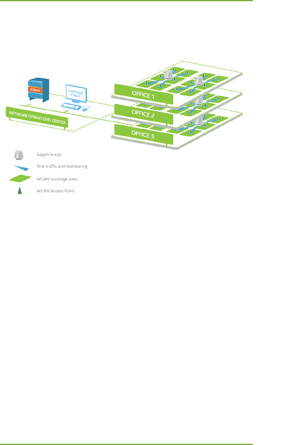
Sapphire Eye is a monitoring station for WLAN environments. Unlike a common access point or
client, the Eye monitoring station uses advanced broadband antenna technology, which
creates an exceptionally large coverage area. Consequently, one Eye can monitor several
access points, or WLAN cells. The typical number of monitored cells is 5–8. Eye is protected
against dust and water (conformant to IP55 or IP65 specifications, depending on the model),
so it can be installed outdoors also in challenging environments.
In the picture above:
• The monitoring station (Eye) is the grey cone-like object in the center;
• the Carat management interface is on the service provider’s premises (top left
corner);
• the customer’s premises have a wireless network with six access points (center part
of the picture, access points in red);
• there is one monitoring station on the customer’s premises (the colored lobes
depict the station’s directional antennas and their range);
• a problem has occurred in an access point in the red lobe;
• the problem can be seen in the monitoring interface or in a report as a falling
performance indicator value (lower right corner).
In Sapphire, the management tool Carat and monitoring station Eye work as a client and
server, with Eye being the server for Carat. The traffic between the client and server is strongly
encrypted and uses 7signal’s proprietary management protocol. This makes it possible to
manage the monitoring stations from geographically distant locations and over insecure
networks.

2 Sapphire Eye 4
7signal Ltd, Panuntie 6, FI-00620 HELSINKI, FINLAND, +358 40 777 7611, info@7signal.com, www.7signal.com
7signal Sapphire Carat Carat User Guide Release 3.1
A monitoring station conducts both passive and active measurements in a WLAN environment.
The passive measurements consist of listening to data traffic that uses the IEEE 802.11
protocol and of general analysis of the radio frequency spectrum in the coverage area. Passive
measurements have no effect on the functionality or utilization rate of the target network, or
the effect is very small (probe request transmissions). During active measurements, Sapphire
Eye contacts each monitored access point in turn and uses the network services via the WLAN;
i.e., it acts as a client in the network. Using both active and passive measurements, the 7signal
WQA solution can monitor the experienced network performance along the entire length of
the service chain and locate problems in both WLAN and LAN environments.

3 Sapphire Carat 5
7signal Ltd, Panuntie 6, FI-00620 HELSINKI, FINLAND, +358 40 777 7611, info@7signal.com, www.7signal.com
7signal Sapphire Carat Carat User Guide Release 3.1
3 SAPPHIRE CARAT
With the Sapphire Carat management tool, you can manage the Sapphire Eye monitoring
stations, run interactive and real-time measurements, configure and manage automatic
measurements, and generate reports of the measurement results. The reports shows
measurement results in tables and charts.
Sapphire Carat stores the profiles used in the automatic testing of the monitored network, and
the network’s access rights information. Sapphire Carat can be used interactively to test
various areas of the network, or it can be left running in the background for continuous
collection of test results.
Key features:
• Status information on the radio network’s availability and usability;
• Availability of a production service;
• Overview of data traffic from the client to the production server;
• Packet-level load measurement and traffic analysis in a radio network ;
• Tests at application level;
• Properties, signal levels, and noise levels of the radio frequency environment;
• Statistical analyses, averages, deviations, and distributions;
• Monitoring of data security settings;
• Location of interference;
• Alarms.

4 Sonar 6
7signal Ltd, Panuntie 6, FI-00620 HELSINKI, FINLAND, +358 40 777 7611, info@7signal.com, www.7signal.com
7signal Sapphire Carat Carat User Guide Release 3.1
4 SONAR
The role of the Sonar test server in 7signal Sapphire is to emulate one of the customer’s
production servers. Sapphire Eye connects to Sonar to measure QoS provided by the network.
Measurements are performed both directions (uplink and downlink). Uplink means traffic from
end-user device (e.g Eye) towards network (e.g. Sonar). Downlink means traffic from network
towards the end-user device.
Single Sonar can serve several monitoring stations which has access through IP networks to
Sonar. One Sonar can therefore be used as the test point for several networks.
The 7signal Sapphire WQA solution supports the concurrent use of several Sonar test servers,
which means that Sonar can be installed on several servers within a company. Using several
Sonars enables the company to detect and locate problems in its network. Sonar can be
located in the same network as the access points, in a server room in the same building, or
anywhere on the Internet – such as in the centralized identification and authorization center of
an international organization.

5 Sapphire Loupe 7
7signal Ltd, Panuntie 6, FI-00620 HELSINKI, FINLAND, +358 40 777 7611, info@7signal.com, www.7signal.com
7signal Sapphire Carat Carat User Guide Release 3.1
5 SAPPHIRE LOUPE
Sapphire Loupe is the performance and QoS analysis tool in the WQA solution. Loupe cannot
be used to control Sapphire’s functions and measurements themselves.
Loupe makes the network’s key performance indicators (KPIs) available at a glance, or in more
detailed form for a given time period. Loupe is browser-based, so authorized persons can use
any of the most common browsers to view the results as long as they have an Internet
connection. The result summaries can be saved as plain text to comma separated value files
(CSV files), or as PDF files, preserving the formatting. The plain-text material can be used in
many ways, including import into a spreadsheet.
There is a separate user document for the Sapphire Loupe.

6 Carat user Interface 8
7signal Ltd, Panuntie 6, FI-00620 HELSINKI, FINLAND, +358 40 777 7611, info@7signal.com, www.7signal.com
7signal Sapphire Carat Carat User Guide Release 3.1
6 CARAT USER INTERFACE
The Carat user interface (GUI) is a stand-alone java client. The purpose of the Carat user
interface is to configure and manage the Sapphire solution. Several users can access and
configure single Carat simultaneously.
6.1 Menus
6.1.1 Navigation
The menu contents are dynamic based on context, user access rights and the current license.
Menu
Description
Submenus
File
Log in / log out, lock the session, and
close the application.
Lock session
Log in
Log off
Exit
Edit
Enter settings for applications used for
viewing the exported result files. Specify
the server for outgoing mail.
Configure tools
SMTP server
View
Configure and view Sapphire’s general
settings.
Network topology
Alarm
Manage
Manage Sapphire’s general settings:
- alarms
- user management
- access keys to radio networks
- test end point settings
- administration of target network
client information
- settings for automatic reporting
- remote management of
monitoring station software
Alarm configuration
Users and groups
Access Control
Network Keys
Test end points
Alarms
Email
SNMP
Network clients
SLA Definitions
Automated report
configuration
Eye software
management
Change password
Test Profiles
Tools
Start and stop the automatic test profile.
Start sequential testing
Stop sequential testing
Eyes auto test
management
Window
Refresh the main window of the user
interface.
Refresh
Help
Read user documentation and general
information about the system
installation.
Release notes
Carat User guide
Loupe User guide
About
6 Carat user Interface 9
7signal Ltd, Panuntie 6, FI-00620 HELSINKI, FINLAND, +358 40 777 7611, info@7signal.com, www.7signal.com
7signal Sapphire Carat Carat User Guide Release 3.1
6.2 Network Topology
The Network topology is a hierarchical tree displaying hierarchy from the Organization to Eyes
and Access Points. The user can select from multiple ways to access the network: either via
monitoring stations or via the network’s service areas. Both methods support network testing,
but monitoring stations can only be managed by using their respective icons.
The network hierarchy is displayed as a tree, with an icon representing each item at each
node. If the item has functionality, you can bring it into view by right-clicking the icon.
Topology
Node
Icon
Description
Submenus
Organization
In the Organization menu,
you can add organizations,
locations and service areas to
the organization that is being
created.
Edit
View wireless network
Add location
Add organization
Remove organization
Bind SLA
Location
From the Location menu, you
can set the network’s
physical location (e.g.,
country, city, or building). A
location is always attached to
a higher-level location or
organization.
Edit
Add Location
Add service area
Remove location
Add Link Group
Bind SLA
Service area
A service area is a location
where you can install a
monitoring station. A service
area is determined by the
coverage area of the
monitoring station, not by
the coverage area of the
target network.
A service area can have a
floor plan.
Edit
Add Eye
Bind wireless network
Remove service area
Allowed channels
Floor plan
Bind SLA
Eye
A monitoring station always
belongs to a service area.
Edit
Remove Eye
(De)activate
Network scan
Client scan
Spectrum analysis
Noise Monitor
Manual tests
Bind to test profiles
Unbind from test profiles
Automated test status
Bind SLA
Wireless
network
This menu describes the
target network, which can be
located in one or more
service areas. A service area
can contain several target
networks. This menu is used
Add key
Edit
Unbind wireless network
Allowed channels
Bind SLA

6 Carat user Interface 10
7signal Ltd, Panuntie 6, FI-00620 HELSINKI, FINLAND, +358 40 777 7611, info@7signal.com, www.7signal.com
7signal Sapphire Carat Carat User Guide Release 3.1
to configure the encryption
method used in the network.
Access Point
In this menu, you can
perform tests and set alarm
limits for an access point.
Access point info
Active tests
Bind to alarm limit group
Unbind to alarm limit group
Remove access point
Bind SLA

7 Starting the Carat configuration 11
7signal Ltd, Panuntie 6, FI-00620 HELSINKI, FINLAND, +358 40 777 7611, info@7signal.com, www.7signal.com
7signal Sapphire Carat Carat User Guide Release 3.1
7 STARTING THE CARAT CONFIGURATION
The access rights and user management heavily relies a group-based model. The group is the
starting point: every user belongs to one of the groups and the group determines the access
rights of any given user. The technical details and management instructions are in the next
section.
Any objects in the system – Eyes, Sonars, topology elements such as Organizations and
Locations – belong to some administrative group. Objects that do not belong to a certain
group are also invisible to the group. This isolation is very low-level in 7signal Sapphire in order
to enable safe and secure operations in large setups with numerous and heterogeneous
organizations.. 7signal Sapphire supports multiple organizations that are under completely
different administration and must remain unaware of each other.
NOTE: To fully utilize this feature it is strongly advised that a role called Solution
Administrator (see the next section on user and group management) is used only
to create other Administrators (Organization Administrators).
The recommended minimum setup for an operational 7signal Sapphire is to have default
admin user for general handling of users and groups and admins of one or more organizations.
Any organization needs two users: one for administration and one for configuration network
tests etc.
7.1 How To Create The Minimum Set Of Users
The system default user is the ‘Solution Administrator’ belonging to Solution Administrator
Group. This requires no other action than the initial login and changing the default password
to a non-default password.
As ‘Solution Administrator’
1. Choose ‘Manage | Users and Groups’ for user account management from the top-
menu.
2. Create a new group for the administrators of the organization.
Use a descriptive name, f ex NewAdminGroupForOrganizationX
3. Create a new admin user for the organization.
Use a descriptive name, f ex LocalAdministrator1.
4. Logout
As ‘LocalAdministrator1’ created in the previous step
1. Choose ‘Manage | Users and Groups’ for user account management from the top-
menu.
2. Create a new group for the configurators of the organization under previously created
administrator group.
Use a descriptive name, f ex NewConfigGroupForOrganizationX

7 Starting the Carat configuration 12
7signal Ltd, Panuntie 6, FI-00620 HELSINKI, FINLAND, +358 40 777 7611, info@7signal.com, www.7signal.com
7signal Sapphire Carat Carat User Guide Release 3.1
3. Create a new configurator user to the Configurator group.
Use a descriptive name, f ex LocalConfigurator1.
4. Continue using Sapphire.
All other configurations related to network topology, test profiles, wlan network
keys etc. should be made by the user LocalConfigurator1 to enable proper
operation of the automated object access rights management system.
Some top-level operations for Solution Administrator are explained right below
7.2 Automated Tests
Top-menu selection “Tools | Start automated tests” affects only those objects that are
accessible to the user issuing the command. Stopping works similarly.
Solution Administrator level user starts and stops testing system-wide i.e. all the monitoring
stations. Local Administrator may affect the monitoring stations only inside their own
administrative boundary i.e. only part of the monitoring stations start/stop. However it is
advised to use Configurator level users to manage automated testing.
7.3 Access Rights
The access rights is an accessible pane in the “Manage” menu. When one follows the intended
way of user and group definition, the contents and actions in the “Access Rights” pane are
redundant. The feature remains activated but the use of it is discouraged and thus not
instructed in detail.
For sandbox testing and non-warranted try-outs: the left panel contains actual users and
groups and related access rights. The right panel contains all objects in 7signal Sapphire. With
combinations of right-clicks and drag&drops fine-level adjustment and changes to access rights
are possible.

8 User Management 13
7signal Ltd, Panuntie 6, FI-00620 HELSINKI, FINLAND, +358 40 777 7611, info@7signal.com, www.7signal.com
7signal Sapphire Carat Carat User Guide Release 3.1
8 USER MANAGEMENT
User management in 7signal Sapphire is based on user groups. A user's access rights in the
system derive from the user group that the user belongs to. A user may belong to one or more
user groups.
In addition to normal user management the Sapphire system supports user group specific view
virtualization. The system can be configured so that different user groups have access to
different objects that have been created into the system. For instance, one user group may
have access to all objects and two subgroups of that group may only have access to a portion
of all objects. It is also not necessary for the subgroups to have access to any of the same
objects.
User management is also restricted in the same manner as object management. An
administrator user only has access to the users created to subgroups in addition to any users
belonging to the same administrator group he/she belongs to.
Users belonging to the Sapphire admin group have access to the entire system.
8.1 User Groups And Object Permissions
Almost every object created in the Sapphire system includes an access control list (ACL). An
object's ACL is mainly determined by the user group of the user that creates the object in
question.
Note that objects are also created through automatic testing. For example access points,
wireless clients and alarms created this way. Objects created as a result of automatic testing
inherit their ACL from the Eye that conducted the test.
The Sapphire system also includes the functionality to transfer access rights of objects from
one user group to another.
8.2 User Group Hierarchy
The Sapphire system supports two types of user groups: normal user groups and referencing
user groups.
A normal user group can be created either as a new root group or as a subgroup to an already
existing user group. When new groups are created as subgroups under an existing user group,
the existing group inherits access rights to all objects that its subgroups have access rights to.
This inheritance rule applies to the whole user group hierarchy meaning that the root user
group in a hierarchy gets access rights recursively from all subgroups. Access rights of
referencing user groups are not inherited in this way.
A referencing user group can be created for any group except the Solution Administrator
group. A referencing user group always has the same access rights as the user group it
references. The only difference is that a referencing user group cannot be granted the same
access level as the group it references. A common use for a referencing user group is to have it
reference for example an organization’s configuration group. This way the referencing group’s
users can view the configuration group’s objects, but cannot configure the system.
8 User Management 14
7signal Ltd, Panuntie 6, FI-00620 HELSINKI, FINLAND, +358 40 777 7611, info@7signal.com, www.7signal.com
7signal Sapphire Carat Carat User Guide Release 3.1
8.3 User Access Levels
The Sapphire system supports three elementary access levels for user groups: Reporter,
Configurator and Administrator. Access rights are inherited from lower to higher levels:
Reporter users only have their own level’s access rights, Configurator users have reporter level
rights plus additional rights granted by their configurator level, and Administrator users have
all rights.
There are four levels of access rights:
• Solution Administrator – system-wide super-user that may be the only user in small
set-ups and should be used only for other administrator definitions in large-scale
environments
• Administrator – full access and management rights
• Configurator – full access rights, no user management rights
• Reporter – access rights to alarms and reports
8.4 User Group And User Management
The Sapphire Carat user management dialog can be accessed from the main menu by selecting
"Manage | Users and groups". Only administrator level users can access user group and user
management in the Sapphire system.
When the user management dialog is opened, a tree view showing the users and user groups
currently existing in the system opens to the left of the dialog.
8.5 User Groups
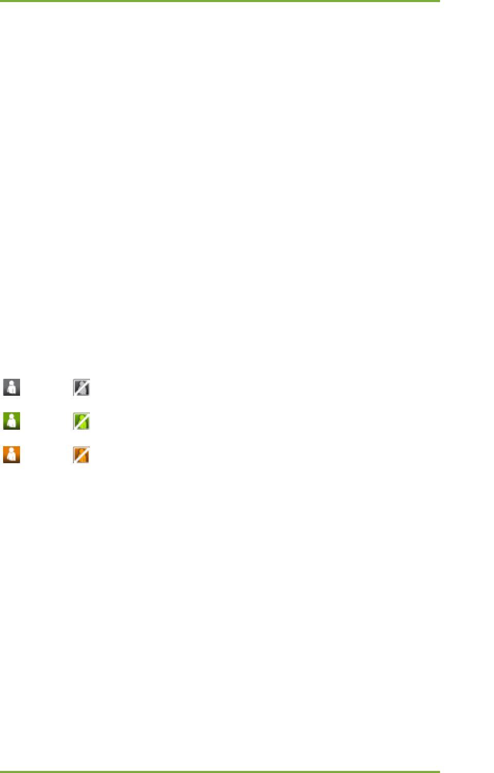
8.5.1 Related icons
Reporter group
active group referencing group inactive group
Configurator group
active group referencing group inactive group
Administrator group
active group referencing group inactive group
8.5.2 User Group Parameters
Name - The name of the user group
Description - A description of the group
Service Role - Defines access rights for the group's users in the Sapphire system
Type - The group type (normal/referencing)
Status - The group status (active/inactive)

8 User Management 15
7signal Ltd, Panuntie 6, FI-00620 HELSINKI, FINLAND, +358 40 777 7611, info@7signal.com, www.7signal.com
7signal Sapphire Carat Carat User Guide Release 3.1
8.5.3 Adding User Groups
A new user group can be added into the system in three different ways:
1. As a new root group under which to start creating a new user group hierarchy.
2. As a subgroup to an already existing user group.
3. As a symbolic (referencing) group for an already existing group.
Adding a group can be done by right-clicking on either the "Groups and users" node in case n:o
1 or an existing user group in cases 2 and 3 and selecting "Add instance group" in case n:o 1
and n:o2 or "Add symbolic group" in cases n:o 3 from the pop-up menu.
Steps to create a new group:
1. From the top menu bar select “Manage | Users and Groups” to open a pane on left
2. Right-click the root object named “Users and Groups” or an existing group to get a
submenu
3. Select “Add group” to open a pane on right
4. Enter the relevant group information
a. user name: login name for the user
b. (optional) Description: free-text field for the group description
c. Role: group access right level. The field is dynamic, the super-group dictates
the default level and available range of valid access level.
d. Status: Active or inactive. Only users in an active group may login.
5. Save the group by clicking “Save”
8.5.4 Editing User Groups
The user group editing dialog can be accessed by right-clicking the desired user group and
selecting "Edit" from the pop-up menu.
An example of editing a user group:
1. Log in as an administrator group user
2. Open the user group and user management dialog by clicking "Manage | Users and
Groups" from the top menu bar
3. Select the desired user group for editing by right-clicking on it and choosing "Edit"
from the pop-up menu
4. Make the desired changes to the user group’s settings
5. Save the changes by clicking on the "Save" button
8.5.5 Removing User Groups
A user group can be removed by selecting the group to be removed by right-clicking on it and
selecting "Remove Group" from the pop-up menu. The following criteria must be satisfied
before a user group can be removed:
`
1. The group must be empty of users
2. The group must not have any subgroups
3. The group must not own any objects
An example of removing a user group:
8 User Management 16
7signal Ltd, Panuntie 6, FI-00620 HELSINKI, FINLAND, +358 40 777 7611, info@7signal.com, www.7signal.com
7signal Sapphire Carat Carat User Guide Release 3.1
1. Log in as an administrator group user
2. Open the user group and user management dialog by clicking "Manage | Users and
Groups" from the top menu bar
3. Right-click on a group that satisfies the removal criteria and select "Remove" from the
pop-up menu
8.5.6 User Group Status
In certain situations it may be desired to inactivate some user group. An inactive user group
has no access rights in the system. A user group can be inactivated by right-clicking on the
desired group and selecting "Inactivate" from the pop-up menu. An inactive group can be re-
activated by right-clicking on the group and selecting "Activate" from the pop-up menu.
An example of changing a group’s status:
1. Log in as an administrator group user
2. Open the user group and user management dialog by clicking "Manage | Users and
Groups" from the top menu bar
Right-click on the desired group and select "Inactivate" from the pop-up menu
8.6 Users
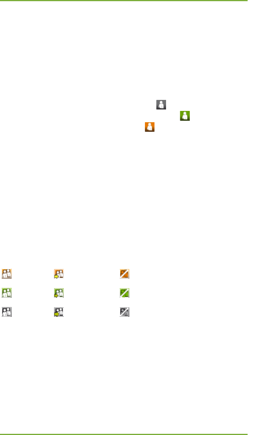
8.6.1 Related icons
Administrator user
active inactive
Configurator user
active inactive
Reporter user
active inactive
Parameters
User name - User name
Alias - An alias for the user name, for example the user’s real name
Email Address - User’s email address
Phone - User’s phone number
Organization - The Organization that the user belongs to. Useful for example when a
service provider wants to give access rights to clients it manages.
Status - User’s status
Password/Confirm password: Password/Confirm password
When creating a new user the user name, status and password fields are required, the rest of
the parameters are optional.
8.6.2 Adding Users (New)
A new user can be added by right-clicking on the user group that the user is to be added into
and selecting "Add user" from the pop-up menu.
8 User Management 17
7signal Ltd, Panuntie 6, FI-00620 HELSINKI, FINLAND, +358 40 777 7611, info@7signal.com, www.7signal.com
7signal Sapphire Carat Carat User Guide Release 3.1
Steps to create a new user:
1. From the top menu bar select “Manage | Users and Groups” to open a pane on left
2. Right-click the relevant group to get a submenu
3. Select “Add user” to open a pane on right
4. Enter the relevant user information
a. Username: login name for the user
b. (optional) Alias: alternative name for the user
c. (optional) Email address: contact information for the user
d. (optional) Organization: user’s organization
e. Status: Active or inactive. Only active users may login.
f. Password and confirmation: login password
5. Save the user by clicking “Save”
8.6.3 Adding Users By Copying
An existing user can be copied to several groups. This enables one single account to be used on
numerous organizations while preserving the strict access policy.
Steps to copy a user:
1. Create one more group
2. Select a user from a previously existing group and right-click for the menu
3. Select “Copy user”
4. Select the icon of the new group and right-click for the menu
5. Select “Paste user”
The copied account may now access numerous groups. The login of a user belonging to several
groups starts in the typical manner. After successful login a pop-up is shown in order to make
selection of the group used for the login. The possible other groups are invisible after the
chosen group (context) has been chosen.
8.6.4 Editing User Information
A user’s information can be edited by right-clicking on the desired user and choosing "Edit"
from the pop-up menu. User name and password cannot be changed from here.
An example of editing a user’s information:
1. Log in as an administrator group user
2. Open the user group and user management dialog by clicking "Manage | Users and
Groups" from the top menu bar
3. Right-click on the desired user and pick "Edit" from the pop-up menu
4. Change the desired parameters

8 User Management 18
7signal Ltd, Panuntie 6, FI-00620 HELSINKI, FINLAND, +358 40 777 7611, info@7signal.com, www.7signal.com
7signal Sapphire Carat Carat User Guide Release 3.1
5. Save changes by clicking "Save"
8.6.5 Removing Users
A user can be removed by right-clicking on him/her and selecting "Remove" from the pop-up
menu.
An example of removing a user:
1. Log in as an administrator group user
2. Open the user group and user management dialog by clicking "Manage | Users and
Groups" from the top menu bar
3. Right-click on the desired user and pick "Remove" from the pop-up menu
User’s status
If for some reason it is desired to deny a certain user from accessing the system, that user can
be inactivated by right-clicking on the user and selecting "Inactivate" from the pop-up menu.
An inactivated user may be re-activated by right-clicking on him/her and selecting "Activate"
from the pop-up menu.
An example of changing a user’s status:
1. Log in as an administrator group user
2. Open the user group and user management dialog by clicking "Manage | Users and
Groups" from the top menu bar
3. Right-click on the desired user and select "Passivate" or "Activate" from the pop-up
menu
8.6.6 Changing Password For Users
A user’s password can be changed by right-clicking on the user and selecting "Change
Password" from the pop-up menu. This will open a new dialog into which the user’s new
password can be entered.
An example of changing a user’s password:
1. Log in as an administrator group user
2. Open the user group and user management dialog by clicking "Manage | Users and
Groups" from the top menu bar
3. Right-click on the desired user and select "Change Password" from the pop-up menu
4. Input new password
5. Save new password by clicking the "Save" button
9 Network topology configuration 19
7signal Ltd, Panuntie 6, FI-00620 HELSINKI, FINLAND, +358 40 777 7611, info@7signal.com, www.7signal.com
7signal Sapphire Carat Carat User Guide Release 3.1
9 NETWORK TOPOLOGY CONFIGURATION
Network topology is defined in Carat to reflect geography and organization and help with
reporting necessary entities separately. Network topology consists of organizations, locations,
service areas, Eyes and managed access points.
9.1 Choosing Networks To Be Monitored
9.1.1 Organization
Sapphire can simultaneously manage networks in several independent organizations. A
company or other organization can have many separate locations. The networks are displayed
in a hierarchical tree starting from the Organization.
A company can have several networks, for different purposes. For example:
• Office network
• Warehouse network
• Guest network
To meet this need, Sapphire can monitor several networks at the same time.
To handle a hierarchy that might grow utterly complex, 7signal uses a tree-structure.
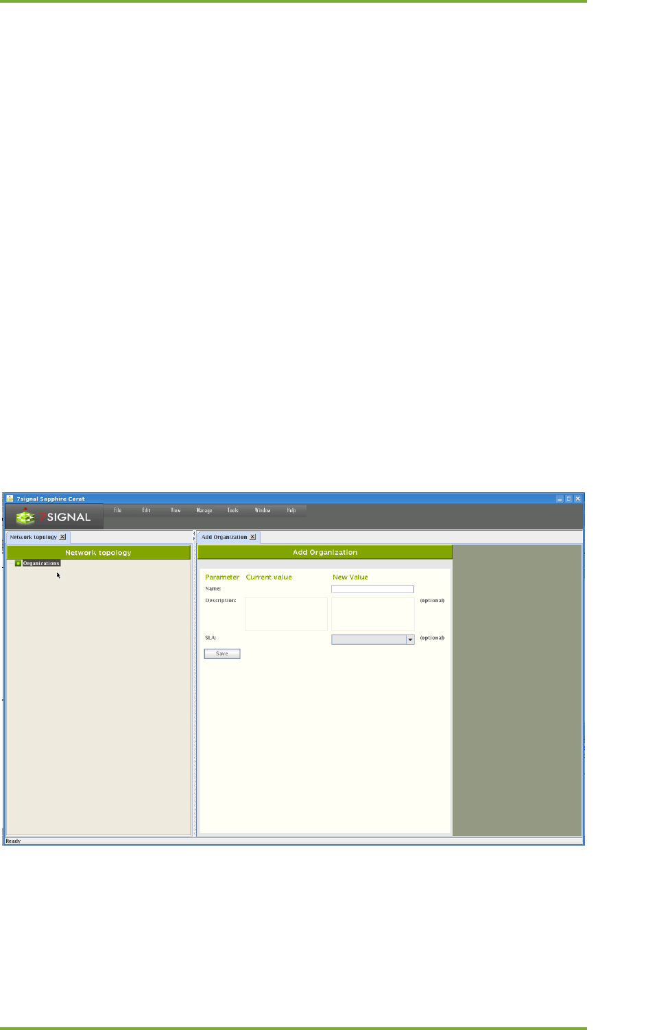
Organization is a starting point to create tree structure. User can add one or more
organizations depending what is an appropriate structure.
1. Right click Organizations node in tree and select “Add Organization”
2. Enter the organization’s name
3. Save by clicking “Save”
4. The Network topology is automatically displayed after saving
9 Network topology configuration 20
7signal Ltd, Panuntie 6, FI-00620 HELSINKI, FINLAND, +358 40 777 7611, info@7signal.com, www.7signal.com
7signal Sapphire Carat Carat User Guide Release 3.1
9.1.2 Addition Network Locations
Location is used to define the network’s location in a precise or descriptive way. A location
might be a city, a part of the city, a building, or a single floor in a building, depending on the
coverage area of the organization’s network. A small organization might have only a single
location, an office. On the other hand, a large organization might have several locations, in
different cities, or a single overall location, such as “Europe,” under which countries and cities
etc. are defined.
1. From the top menu bar, select “View | Network topology”
2. Right-click the organization
3. Select “Add location”
4. Enter the location’s name
5. Select the location type from the pull-down menu
6. Enter an optional description for the location
7. Click “Save”
You can add as many locations as needed to describe the organization’s structure.
After you have added a location, you can add a service area.
1. Right-click a location
2. Select “Add service area”
3. Enter a name for the service area
4. Enter an optional description for the service area
5. Click “Save”

9 Network topology configuration 21
7signal Ltd, Panuntie 6, FI-00620 HELSINKI, FINLAND, +358 40 777 7611, info@7signal.com, www.7signal.com
7signal Sapphire Carat Carat User Guide Release 3.1
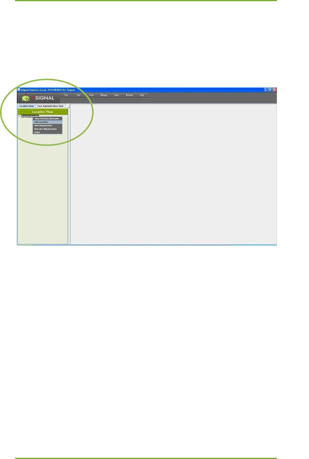
9.1.3 Hidden Networks
7signal Sapphire considers a hidden network to be a property of certain Organization. The
network scans are based on listening and actively requesting beacon information on the
Service Areas. The hidden networks shall not actively transmit beacons nor respond to
requests with partial information only. Due to this the various scans - including the initial scan -
in 7signal Sapphire do not capture hidden networks. Tests related to traffic analysis shall
contain also information on hidden networks but the capture is not used as a technique in
scans.
NOTE: Hiding the network SSID should not be used as a security as it does not
limit sending the beacons or SSID names in payload frames but leaves only
network SSID field blank in beacon signal. Any attacker or publicly available
analysis tool can find hidden network as soon as there are any payload packets in
the network. Even popular operating systems may present hidden network after a
certain period of time. If SSID name is not transmitted, client devices are forced to
start probing their access points continuously. This increase significantly radio
interface traffic overhead and lowers overall network performance.
To add a hidden network to 7signal Sapphire follow the steps below.
1. locate the Organization with a hidden network from the Topology tree
2. Right-click menu on the Service Area and select "Wireless networks"
3. Enter the relevant data on the hidden network on the pane that opened on the right
a. Name type (optional): currently only text strings are supported SSIDs
b. Name: the name of the network - not friendly name but SSID
c. Description (optional): description on the hidden network
d. Contact person (optional): the administrator for the hidden network
e. Key: the name of the wlan network access key that has been stored earlier to
the system
4. Select "Save" to store the data to the system
The pane "All Wireless Networks" shows all defined networks. By choosing the network it is
possible to change the current data. Button "Remove" deletes the network and the related
information from the system.
9.1.4 Removing Networks
All networks managed by Sapphire are displayed in the Network topology. Networks can be
deleted on the organization level. To delete a network from the Network topology:
1. From the Network topology, select the organization containing the wireless network
you wish to remove
2. Right-click the organization and select “View wireless network” – then the “All
Wireless Networks” view is displayed in the right-hand pane
3. Select from the list the network you want to remove
4. Click “Remove”
9 Network topology configuration 22
7signal Ltd, Panuntie 6, FI-00620 HELSINKI, FINLAND, +358 40 777 7611, info@7signal.com, www.7signal.com
7signal Sapphire Carat Carat User Guide Release 3.1
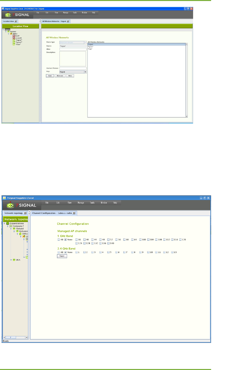
9.1.5 Channel Configuration
In addition to access points, a wireless network can include a controller, which remotely sets
RF parameters for a network. In such a case, the transmitting power and channels may change
over time, due to operator actions or the controller’s own actions.
Sapphire supports controllers via channel configuration so that each managed wireless
network or access point can have its own set of allowed channel changes. Changes that stay
within the preconfigured channel set do not cause an alarm. A change in a channel outside the
preconfigured channel set causes an alarm if that alarm has been activated.
To set up channel configuration, proceed as follows:

9 Network topology configuration 23
7signal Ltd, Panuntie 6, FI-00620 HELSINKI, FINLAND, +358 40 777 7611, info@7signal.com, www.7signal.com
7signal Sapphire Carat Carat User Guide Release 3.1
1. From the top menu bar, select “View | Network topology”
2. Right-click the item (access point, service area or network) for which you want to set
up a channel configuration and select “Channels”
3. Select the allowed channels
4. Select “Save”
7signal Sapphire Enterprise extends this functionality such that all access points or networks
within the service area can have their own allowed and forbidden channels. This allows
Sapphire to monitor the channel configuration in several networks, and to obtain information
on other networks that use channels in unexpected ways. One obvious area of application for
channel configuration is office hotels, which have several small wireless networks that can
interfere with each other.
Extended channel configuration is a feature in the enterprise edition and requires a license.
Each version of Sapphire supports channel configuration in managed networks. To monitor
external networks, you need the enterprise license or some other license model that supports
channel configuration. Without a suitable license, accessing channel configuration in the user
interface does nothing.
10 Eye configuration 24
7signal Ltd, Panuntie 6, FI-00620 HELSINKI, FINLAND, +358 40 777 7611, info@7signal.com, www.7signal.com
7signal Sapphire Carat Carat User Guide Release 3.1
10 EYE CONFIGURATION
10.1 States of Monitoring Stations
The Eye unit may be in an inactive state. This happens if there is no network connectivity to
the monitoring station when a monitoring station is being added to the system. Also, an active
monitoring station may be turned inactive. This allows exceeding the number of monitoring
stations limited by the license. Only active monitoring stations may run the tests but the
topology may contain unlimited number of inactive monitoring stations.
Related icons
active monitoring station
inactive monitoring station
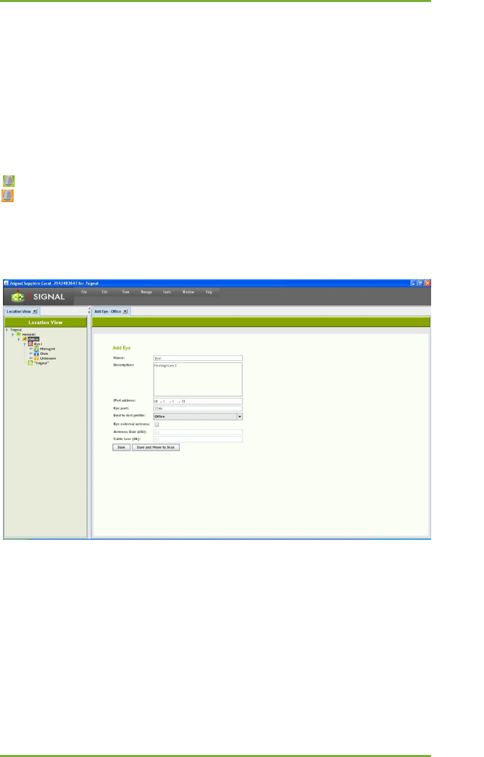
10.1.1 Adding Monitoring Stations
Monitoring stations can be added in the service areas in the Network topology.
1. In the Network topology, select the service area where you want to set up a
monitoring station (Eye)
2. Right-click the service area and select “Add Eye”
3. Enter a name for the Eye
4. Enter the Eye’s IP address
5. Enter a description for the Eye (optional)
a. for example, its location and mount information
6. If you already know the test profile you want to use, you can select it now (for more
information on test profiles, see the section on test profiles in this user guide)
7. Enter the the regional setting. The wlan channels and possibly power options are
dependent on this setting so one should always choose the right setting.
8. (optional): if the hardware exists, it is possible to use the 8th beam or diversity antenna
with the check-box. When selected, one must also provide
10 Eye configuration 25
7signal Ltd, Panuntie 6, FI-00620 HELSINKI, FINLAND, +358 40 777 7611, info@7signal.com, www.7signal.com
7signal Sapphire Carat Carat User Guide Release 3.1
a. Antenna gain
b. Cable loss (measured or estimate)
9. Save the monitoring station settings by clicking “Save” or “Save and move to scan”; the
latter option opens Scan Networks dialog.
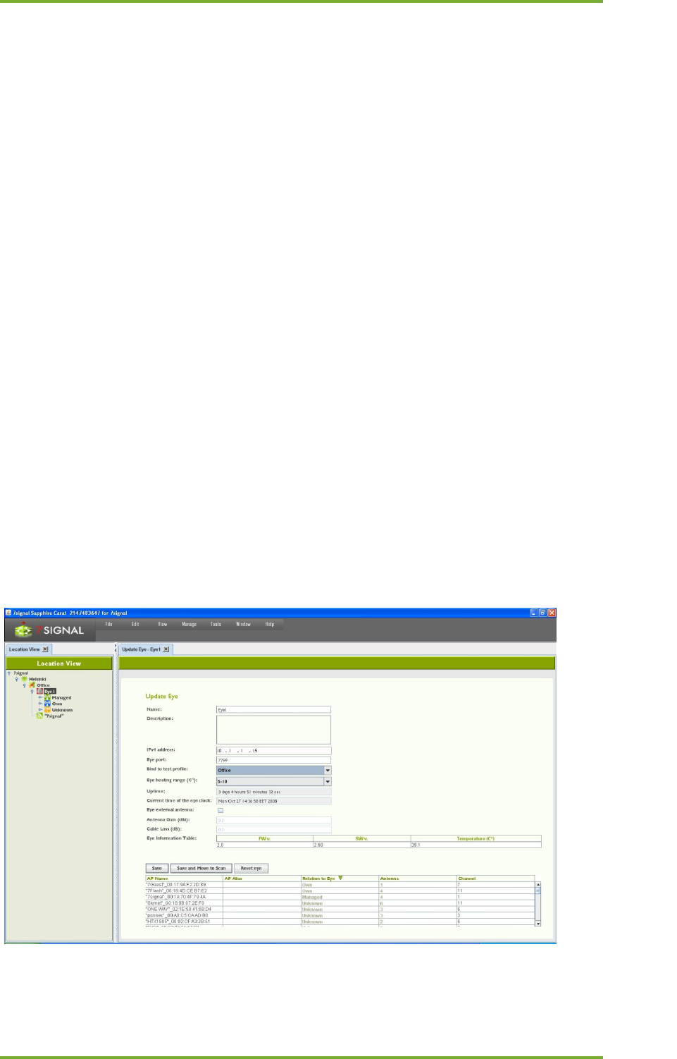
10.1.2 Monitoring Station Settings
1. Activate the monitoring station by right-clicking on it in the Network topology
2. Select “Edit”
a. This opens the settings window in the right pane
3. The settings window allows you to view and edit the following information about the
monitoring station:
a. Name
b. Description
c. IPv4 address
d. TCP port for management traffic
e. Test profile
f. Settings for the Eye’s heating resistor
g. Monitoring station’s uptime
h. Monitoring station’s current time
i. External antenna enabled or disabled
i. gain of the external antenna
ii. cable loss
j. Software versions and temperature of the monitoring station (in a table)
k. Information about the access points within the monitoring station’s range
4. You can also check the information you have entered for the access points:
a. Access point ID (AP ID)
b. Access point name (AP name)
c. The role of the access point with relation to this Eye (AP relation to Eye)
5. Click “Save” to save any changes you have made
10 Eye configuration 26
7signal Ltd, Panuntie 6, FI-00620 HELSINKI, FINLAND, +358 40 777 7611, info@7signal.com, www.7signal.com
7signal Sapphire Carat Carat User Guide Release 3.1
10.1.3 Activating Monitoring Stations
By default, the monitoring station is in active state. This is flagged with the green background
color in the Network topology. An inactive monitoring station would have orange background
color.
It is possible to deactivate the monitoring station. This feature is mainly targeted for
temporary installations. An inactive monitoring station exists in the system and its
measurements are accessible as usual. Only an active monitoring station may produce
measurements and run manual tests. The state management enables consistent user view on
Network topology and measurements.
The use case is to have temporary measurements in numerous locations and to have the
possibility to return to one location and continue with identical monitoring station setup to
keep the measurements comparable. After activating monitoring station, it is recommended
that it would be treated as new if it will be used for monitoring.
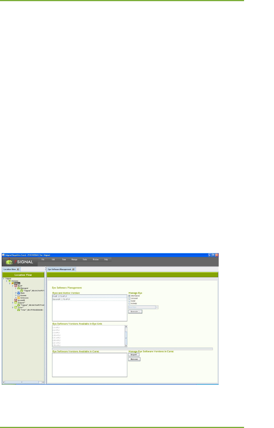
10.1.4 Updating Monitoring Station Software
The software versions of the monitoring stations are managed via Carat. In the “Eye software
management” view, you can manage Eye software via the Carat server’s file system. Software
imported into Carat is visible in a list. Only solution admin has access to software
management.
The center portion of the view lists the software versions of an individual monitoring station
when the monitoring station is activated. At the same time, you can also perform operations
that are available in the top part of the pane.
Operations:
• Information displays the software versions in the activated Eye
• Uninstall uninstalls the software version
• Install adds a software version from the Carat server
• Activate activates the software uploaded to the monitoring station
•
To start using a new software version:
1. From the top menu bar, select “Manage | Eye software management”
10 Eye configuration 27
7signal Ltd, Panuntie 6, FI-00620 HELSINKI, FINLAND, +358 40 777 7611, info@7signal.com, www.7signal.com
7signal Sapphire Carat Carat User Guide Release 3.1
2. At the bottom right, under “Manage Eye software version in Carat,” select “Import”
3. Browse to the desired monitoring station software version in the Carat server file
system and select “Open”; the software is displayed in the “Eye Software Versions
Available in Carat” list
4. Click on the software version you want to install
5. At the top right, under “Manage Eye,” check the “Install” checkbox
6. Select “Execute”
10.2 Initial network scan
When the Eye has been installed or needs to be reconfigured, you must run a network scan.
There are various preconfigured scanning durations. When an Eye has been installed for the
first time, it is recommended that you run the longest scan, titled “Initial scan.” The purpose of
the initial scan is to scan the monitoring station’s radio frequency environment very
thoroughly and to detect the access points suitable for monitoring.
Network scan type
Description
Estimated duration (all antennas and
channels) for channels 1-11 excl. 5 GHz
Initial
First deployment
15–20 min
Slow
Thorough
7–9 min
Regular
Normal
3–4 min
Fast
Quick
less than 1 min
The scan results are presented in a table. An initial scan should be run whenever substantial
physical changes have been made in the environment being monitored (for example, new or
removed walls), or if the Eye’s location has been changed.
The table contains the following information about the WLAN access points detected:
• Network name (ESSID)
• Encryption methods supported by the access point
• MAC address of the access point
• Channel
• Management status (if not known, denoted as “Unknown”)
• Antenna that hears the access point best
• Access point signal strength
• Noise level
The access points in the service area must have a management status. Setting a management
status means that the access point’s existence is acknowledged. Unacknowledged access
points prompt issuing of an alarm if such an alarm has been configured. The management
statuses are as follows:
• Managed: Monitored by this monitoring station
o The recommendation for signal strength is >-65 dBm
• Own: Own access point managed by another monitoring station
• Known: An access point that is an accepted part of the radio frequency environment
(for example, a neighboring network)
o If possible, ensure the access point operates properly and can be accepted
• Unknown: An access point without a monitoring status
o In practice, this status should exist only during network scans in new service
areas; it should not exist in normal use

10 Eye configuration 28
7signal Ltd, Panuntie 6, FI-00620 HELSINKI, FINLAND, +358 40 777 7611, info@7signal.com, www.7signal.com
7signal Sapphire Carat Carat User Guide Release 3.1
The changes are saved in Sapphire Carat’s database and the installed monitoring station. The
test is described in more detail below, under the “Network Scan” description.
11 Creation And Use Of Encryption Keys 29
7signal Ltd, Panuntie 6, FI-00620 HELSINKI, FINLAND, +358 40 777 7611, info@7signal.com, www.7signal.com
7signal Sapphire Carat Carat User Guide Release 3.1
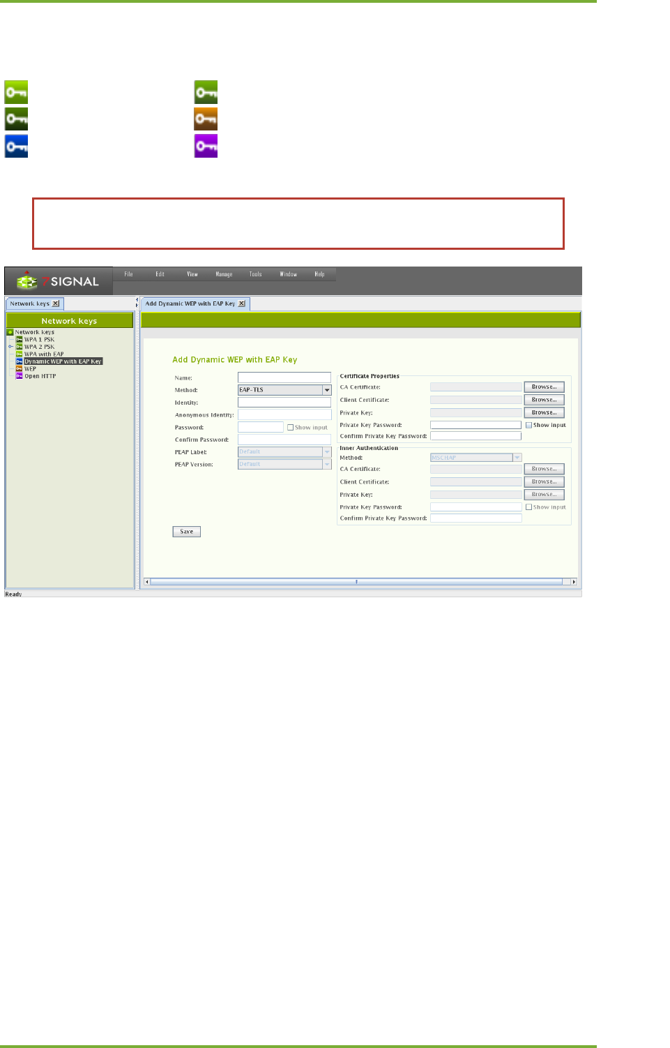
11 CREATION AND USE OF ENCRYPTION KEYS
Related icons
wpa2 encryption wpa eap encryption
wpa 1 encryption wep encryption
ieee encryption http encryption
Before accessing secured wlan, an encryption key for that network should be
created.

11 Creation And Use Of Encryption Keys 30
7signal Ltd, Panuntie 6, FI-00620 HELSINKI, FINLAND, +358 40 777 7611, info@7signal.com, www.7signal.com
7signal Sapphire Carat Carat User Guide Release 3.1
11.1 Supported Encryption Types
Key type
Authentication method
Inner authentication
WPA 1 PSK
WPA 2 PSK
EAP_TLS
GTC
MD5
EAP_PEAP
MSCHAPV2
OTP
TLS
MSCHAP
MSCHAPV2
WPA with EAP
PAP
CHAP
EAP_TTLS
EAP-MSCHAPV2
EAP-TLS
EAP-GTC
EAP-OTP
EAP-MD5
EAP_PSK
EAP_FAST
LEAP
EAP_MSCHAP_V2
EAP_TLS
GTC
MD5
EAP_PEAP
MSCHAPV2
OTP
TLS
MSCHAP
Dynamic WEP with EAP
MSCHAPV2
PAP
CHAP
EAP_TTLS
EAP-MSCHAPV2
EAP-TLS
EAP-GTC
EAP-OTP
EAP-MD5
LEAP
EAP_MSCHAP_V2
WEP 104 Hex
WEP
WEP 104 Asc
WEP 40 Hex
WEP 40 Asc
Open HTTP
11 Creation And Use Of Encryption Keys 31
7signal Ltd, Panuntie 6, FI-00620 HELSINKI, FINLAND, +358 40 777 7611, info@7signal.com, www.7signal.com
7signal Sapphire Carat Carat User Guide Release 3.1
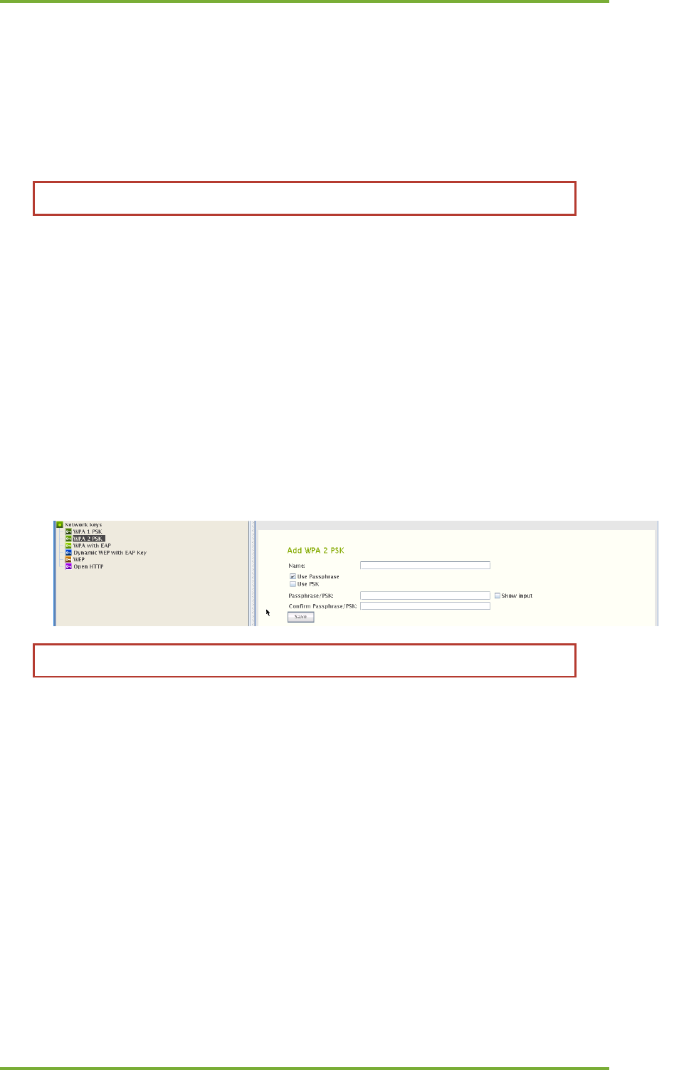
11.2 Adding Encryption Keys (PSK)
11.2.1 Passphrase and pre-shared key
Pre-shared key authentication is sometimes called passphrase authentication. Standard
configuration interfaces allow user to type passphrase (that is converted to PSK) and
proprietary interfaces can allow direct entry of PSK.
WPA and WPA2 are both vulnerable to brute force attacks if you use weak PSK.
The user may enter either a PSK or a passphrase when creating WPA1/2 PSK.
11.2.2 Adding
Add a key by following the instructions below:
1. From the top menu bar, select “Manage | Network Keys” – the available key types and
existing keys are displayed in a hierarchical structure in the left pane
2. Right-click the key type you want to create and select “Add key”
3. Enter a name for the key
4. Enter the data required by the key type
a. There are significant differences in the data required for different key types
b. When “Show input” is checked, the user interface displays the passwords in
plain-text.
5. Save the key by clicking “Save”
After a key has been created, it should be attached to a wireless network.
1. From the top menu bar, select “View | Network topology”
2. In the Network topology, select the network to which you want to add the encryption
key and right-click
3. Select “Add Key”
4. Select a suitable encryption key for the network from the pull-down menu
5. Click “Save”
11.3 On Certificate-Based Encryption
There are input fields for the “CA certificate” and “Client certificate”. It is recommended that
both certificates are added. If one certificate file contains all the information, it should be used
in both of the input fields.
The certificate container is expected to be accessible by the Carat GUI client in the local or
shared file system of the host machine. Accepted formats are the following:
CA certificate – PEM, DER, PKCS12 (aka PFX)
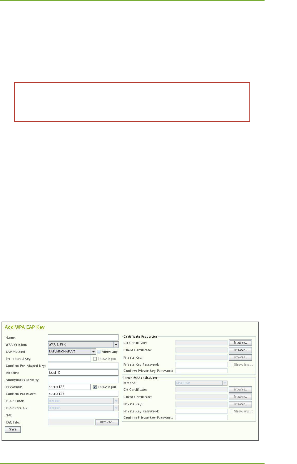
11 Creation And Use Of Encryption Keys 32
7signal Ltd, Panuntie 6, FI-00620 HELSINKI, FINLAND, +358 40 777 7611, info@7signal.com, www.7signal.com
7signal Sapphire Carat Carat User Guide Release 3.1
Private key – PKCS12 (aka PFX)
As a corollary, a single PKCS12 formatted file that contains the CA certificate as well as the
private key, can be used in both of the cases.
If conversions are required to achieve these formats, please consult Your Certificate Authority.
In Linux and Unix environments OpenSSL is commonplace tool and can handle the conversions
required.
TIP: Microsoft environments have certificate files with file extension CER. The file
content format typically is DER. To turn DER files into PEM, please use the
command below:
openssl x509 –informat DER –in <yours>.cer –outformat PEM –out <target>.pem
Windows environments have extension “PFX” to mark a typical certificate container file type.
This format is exactly PKCS12 format that typically has “p12” extension in Linux/Unix world.
7signal Sapphire does not care about the extension but the internal format of the file.
11.4 Multiple Keys Per Eye
There is no limitation to number of keys per Eye or per Wireless Network. If there is only one
key bound to Wireless Network, that key shall be used every time this particular SSID is
associated with. On top of that, each Eye unit may be bound with eye specific key (right-click
on Eye in the topology).
The rationale is to support environments where the actual key dictates both access to the
access point in general and also the access level to the network services beyond the access
point.
11.4.1 Microsoft PKI Infrastructure
One commonplace certificate-based environment is implemented by Microsoft. Typically any
appliance shall have their own account (“machine-account”). It would very challenging to
make the linux-based Eye to serve Windows infrastructure with the proper certificate. An
applicable option is to create one user-account to be used by all Eye units.
When a user-account is in place, the authentication may be defined as follows:

11 Creation And Use Of Encryption Keys 33
7signal Ltd, Panuntie 6, FI-00620 HELSINKI, FINLAND, +358 40 777 7611, info@7signal.com, www.7signal.com
7signal Sapphire Carat Carat User Guide Release 3.1
1. Select “Dynamic WEP with EAP key” to get the dialog above
2. Select WPA key type, either 1 or 2, according the local environment
3. EAP method must be set to “EAP_MSCHAP_V2”
4. Fill in the account user name to the field “Identity”
5. Enter and confirm the account password.
6. Enter Windows infrastructure CA certificate.
7. One may enter the same certificate as “Client Certificate” as well.
The Eye is now properly authenticated in Windows PKI environment.
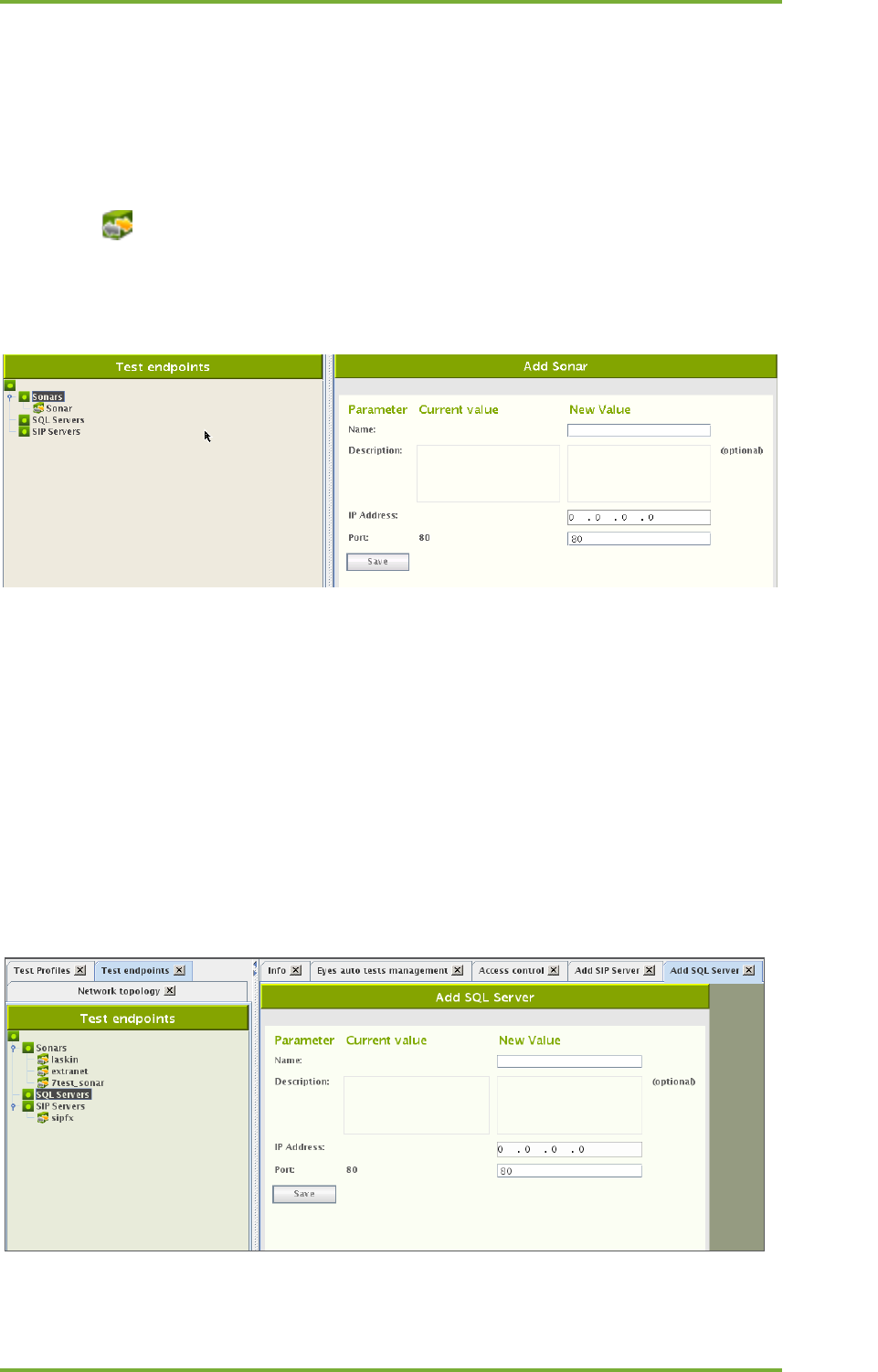
12 Test End-Points 34
7signal Ltd, Panuntie 6, FI-00620 HELSINKI, FINLAND, +358 40 777 7611, info@7signal.com, www.7signal.com
7signal Sapphire Carat Carat User Guide Release 3.1
12 TEST END-POINTS
12.1 Sonar
Sonar is 7signal specific server that handles typical network requests i.e. it emulates numerous
servers in the network.
Sonar (icon ) is the server needed for executing elementary tests. There can be several
Sonar servers configured. Each test can be configured to use any of the configured Sonars.
Configuring Sonar servers makes it easy to define the parameters for the automatic
measurements.
1. From the top menu bar, select “Manage | Test endpoints”
2. Select “Add Sonar” from Sonars tree node after right clicking it.
3. Enter a name for the Sonar instance (Note: The name should be descriptive, especially
when one is using several Sonars)
4. Enter a description for the Sonar (optional)
5. Enter the IP address and TCP port (Note: At this stage, Carat does not verify that the
Sonar actually exists, so ensure that the Sonar exists before you begin testing)
6. Click “Save”
12.2 Generic Test Counterparts
It is possible to run tests towards actual network servers such as SIP servers or database hosts.
Test endpoint definition requires information on networking level but does not require
anything application specific. For example, an SQL server is considered only from connectivity

12 Test End-Points 35
7signal Ltd, Panuntie 6, FI-00620 HELSINKI, FINLAND, +358 40 777 7611, info@7signal.com, www.7signal.com
7signal Sapphire Carat Carat User Guide Release 3.1
point of view while the actual access credentials and test queries are defined per test.
Therefore the endpoint definition is a simple procedure and is similar to all supported test
endpoints.

13 Access Point Information 36
7signal Ltd, Panuntie 6, FI-00620 HELSINKI, FINLAND, +358 40 777 7611, info@7signal.com, www.7signal.com
7signal Sapphire Carat Carat User Guide Release 3.1
13 ACCESS POINT INFORMATION
Related icons
unknown access point (unwanted state)
known access point (in the coverage area but outside administrative domain)
own access point (in administrative domain)
managed access point (target to a monitoring station, in administrative domain)
The access point information can be displayed by right-clicking the access point in the Network
topology and selecting “Access Point Info.” The information includes the following:
• Access point name
• Alias
• Description
• The managing Eye (i.e., the Eye that performs the tests)
• Related Eyes
• ESSID
• Access point type
• The antenna used by the Eye to monitor the access point
• Network
• MAC address
• Alarm limit
• SLA Group
• Encryption
• Beacon Interval
• Country Code
• Environment
• Capabilities
• Channel and channel change history
• legacy bitrates and changes in those
• 802.11n MCS Indexes
• 802.11n HT Capabilities
• 802.11n seconadary Channel
• 802.11n Control Channel
• 802.11n HT Parameters
• WMM Category: Best Effort
• WMM Category: Background
• WMM Category: Video
• WMM Category: Voice
13.1 Replacing Access Points
7signal Sapphire saves all access points it has noticed. The changes in the hardware may be
due removal of existing hardware or because of extensions of the current network. These
cases are handled by inactivation of the removed access points or scanning and saving the new
ones.
The hardware replacements require a different approach. The new equipment shall have new
MAC addresses and this causes a discontinuity in the measurements as it is considered a new
access point in the target network. If this is not the intention and the new equipment should
totally replace an access point that was previously in Managed more, 7signal Sapphire must be
informed.

13 Access Point Information 37
7signal Ltd, Panuntie 6, FI-00620 HELSINKI, FINLAND, +358 40 777 7611, info@7signal.com, www.7signal.com
7signal Sapphire Carat Carat User Guide Release 3.1
To retain the measurement history with a new hardware:
1. Scan the network to get hold of the new access point hardware
2. Right-click on the access point that has been replaced to summon the edit dialog
3. Locate the replace panel and choose from the drop-down list the new access point that
shall assume the role of the replaced access point.
The intended use of this feature is to help with replacing identical hardware. If the hardware is
not identical, the results may be many-fold. SLAs and alarm thresholds should be checked, for
example.
There is also possibility to enable automatic access point change logic in carat server. This can
be done configuring Wireless Network to allow automatic changes.
1. Open Edit Wireless Network by right clicking network in tree and selecting “Edit”
2. Enable “Allow automatic BSSID changes”
3. Save Wireless Network Configuration.

14 Links And Link Groups 38
7signal Ltd, Panuntie 6, FI-00620 HELSINKI, FINLAND, +358 40 777 7611, info@7signal.com, www.7signal.com
7signal Sapphire Carat Carat User Guide Release 3.1
14 LINKS AND LINK GROUPS
In 7signal Sapphire a link denotes an end to end connection between an Eye monitoring
station and a Sonar server. Link consists of a monitoring station, an access point and a Sonar
server. In the Network topology links are positioned below the managed access points. 7signal
Sapphire forms the links automatically when it detects an established end to end connection.
Related icons
link link group
A link group is a grouping of links defined by a user. A user can create a link in a Location in the
Network topology. The main purpose of a link group is to give users the ability to easily bind
one SLA group to multiple links with similar expected level of service.
Links and link groups enable the versatile binding of SLA groups formed from service level
agreements to end to end connections. For example an SLA group bound to an organization is
applied to all topology elements within that organization. However, this can be overridden by
binding different SLA groups to specific links or link groups, in which case their compliance
with the service level agreement is determined by measuring against the KPIs defined in their
own SLA group, instead of the SLA group bound to the organization.
14.1 Forming Links
7signal Sapphire Carat forms a link automatically once a test profile with a Sonar definition is
bound to a monitoring station.
For example when a test profile containing active tests to two Sonars ("Sonar1" and "Sonar2")
is bound to a monitoring station ("Eye1") with two managed access points ("AP1" and "AP2")
7signal Sapphire carat forms the following links:
1. Eye1 - AP1 - Sonar1
2. Eye1 - AP1 - Sonar2
3. Eye1 - AP2 - Sonar1
4. Eye1 - AP2 - Sonar2
14.2 Removing Links
7signal Sapphire Carat automatically removes a link if one of its components (the monitoring
station, access point or Sonar) is removed. Because links are formed automatically it may be in
certain rare situations necessary for the user to remove links one deems unnecessary.
Remove a link as follows:
1. Click on "View | Network topology" from the top menu bar
2. Right-click on the link to be removed from the tree hierarchy
3. Choose "Remove link" from the pop-up menu
4. Confirm link removal

14 Links And Link Groups 39
7signal Ltd, Panuntie 6, FI-00620 HELSINKI, FINLAND, +358 40 777 7611, info@7signal.com, www.7signal.com
7signal Sapphire Carat Carat User Guide Release 3.1
14.3 Creating Link Groups
Create a link group as follows:
1. Click on "View | Network topology" from the top menu bar
2. Right-click on the desired Location into which the link group is to be added
3. Choose "Add Link Group" from the pop-up menu. A dialog for adding a link group is
opened to the right.
4. Name the link group
5. Define the SLA group to be bound to the link group (optional)
6. Click "Save"
14.4 Removing Link Groups
Remove a link group as follows:
1. Click on "View | Network topology" from the top menu bar
2. Right-click on the link group to be removed from the tree hierarchy
3. Choose "Remove" from the pop-up menu
4. Confirm link group removal
14.5 Adding Link To Group
Add a link to a link group as follows:
1. Click on "View | Network topology" from the top menu bar
2. Drag the link to the desired link group
14.6 Removing Links From Group
Remove a link from a link group as follows:
1. Click on "View | Network topology" from the top menu bar
2. Right-click on the link (under a link group) to be removed from the tree hierarchy
3. Choose "Remove link" from the pop-up menu
4. Confirm link removal
15 Alarms 40
7signal Ltd, Panuntie 6, FI-00620 HELSINKI, FINLAND, +358 40 777 7611, info@7signal.com, www.7signal.com
7signal Sapphire Carat Carat User Guide Release 3.1
15 ALARMS
Related icons
alarm configuration alarm configuration group
critical alarm network error
informational message warning message
The system alarms are initiated by significant changes in the monitored network's status or
topology. It is possible to send the alarms to an SNMP system. Please see the instructions later
in this document.
Alarms are used through alarm groups to which the desired alarms can be assigned. There is a
preconfigured alarm group, Global Alarms, which is active by default. The alarms will then be
issued by any access point in the network. The Global Alarms group includes the following
alarms:
• Managed Access Point Down
• Offending Channel Changes of Managed Domain
• Offending Channel Changes of External Domain
15.1 Creating Alarm Groups
You can extend the Global Alarms group or create new alarm groups. It is recommended that
you create new groups. To create a group, proceed as follows:
1. From the top menu bar, select “Manage | Alarm configuration”
2. Select “Alarm Groups” and right-click it
3. Select “Add Alarm Group”
4. Enter a name for the alarm group
5. Select the alarms by dragging them from “Alarm Templates” to the alarm group pane
6. When you have added all the alarms you want, select “Save”
Modification of alarms in a group
The table below lists the alarms. Some of them have parameters that can be modified. To
modify the parameters of an alarm, proceed as follows:
1. Select the alarm to be modified in the alarm group
2. Right-click and select “Edit”
3. Modify the parameter value
4. Select “Update”
Menu
Description
Modifiable?
Managed Access Point Not
Responding
The alarm is activated when a managed
access point does not respond. This is a
critical alarm.
No
Channel Interference
The alarm is activated when a new access
point with a strong signal is detected on a
managed channel. This is a warning alarm.
Yes
Managed Access Point Security
Settings Changed
The alarm is activated when the security
settings of a managed access point are
changed. This is a critical alarm.
No

15 Alarms 41
7signal Ltd, Panuntie 6, FI-00620 HELSINKI, FINLAND, +358 40 777 7611, info@7signal.com, www.7signal.com
7signal Sapphire Carat Carat User Guide Release 3.1
15.2 Binding Alarm Groups To Access Points
Alarms can be configured on a per-access-point basis by binding an alarm group to an access
point. Only an existing group can be bound to an access point.
1. In the Network topology, right-click the access point to which you want to bind the
alarms
Managed Access Point
Channel Violation
The alarm is activated when a managed
access point starts to use a restricted
channel. This is a warning alarm.
No
Non-Managed Access Point
Channel Violation
The alarm is activated when an external
access point starts to use a restricted
channel. This is a warning alarm.
No
Unknown Access Point
Detected
The alarm is activated when an unknown
access point is detected. This is a warning
alarm.
Yes
End to end latency time
exceeded.
The alarm is activated when the average
round-trip time in a ping test exceeds the
set limit. This is a warning alarm.
Yes
End-to-End Connection Loss
The alarm is activated when ping tests fail.
This is a critical alarm.
Yes
Retransmission Rate Exceeded
The alarm is activated when the
retransmission rate exceeds the set limit.
This is a critical alarm.
Yes
DCHP Server Unreachable
The alarm is activated on DHCP timeout.
This is a critical alarm.
Yes
Access Point MAC Change.
Alarm is activate when BSSID’s mac
changes.
No
Attach Success Rate
Alarm is activated when Attach Success
Rate falls under configured value.
Yes
DHCP Server Success Rate
Alarm is activated when DHCP success Rate
falls under configured value.
Yes
Beacon Availability
Alarm is activated when beacons are not
detected under configured value.
yes
FTP Download Throughput
Alarm is activated when throughput is
lower than configured value.
Yes
FTP Upload Throughput
Alarm is activated when throughput is
lower than configured value.
Yes
VoIP MOS, listen quality
Alarm is activated when listening quality
drops under configured value.
Yes
VoIP MOS, Talk quality
Alarm is activated when Talk quality drops
under configured value.
Yes
Ping Success Rate
Alarm is activated when Ping success rate
drops under configured value.
Yes
FTP Success Rate
Alarm is activated when FTP success rate
drops under configured value.
Yes
VoIP Success Rate
Alarm is activated when VoIP test success
rate drops under configured value.
Yes
Internet Availability
Alarm is activated when Internet
availability is lost.
No
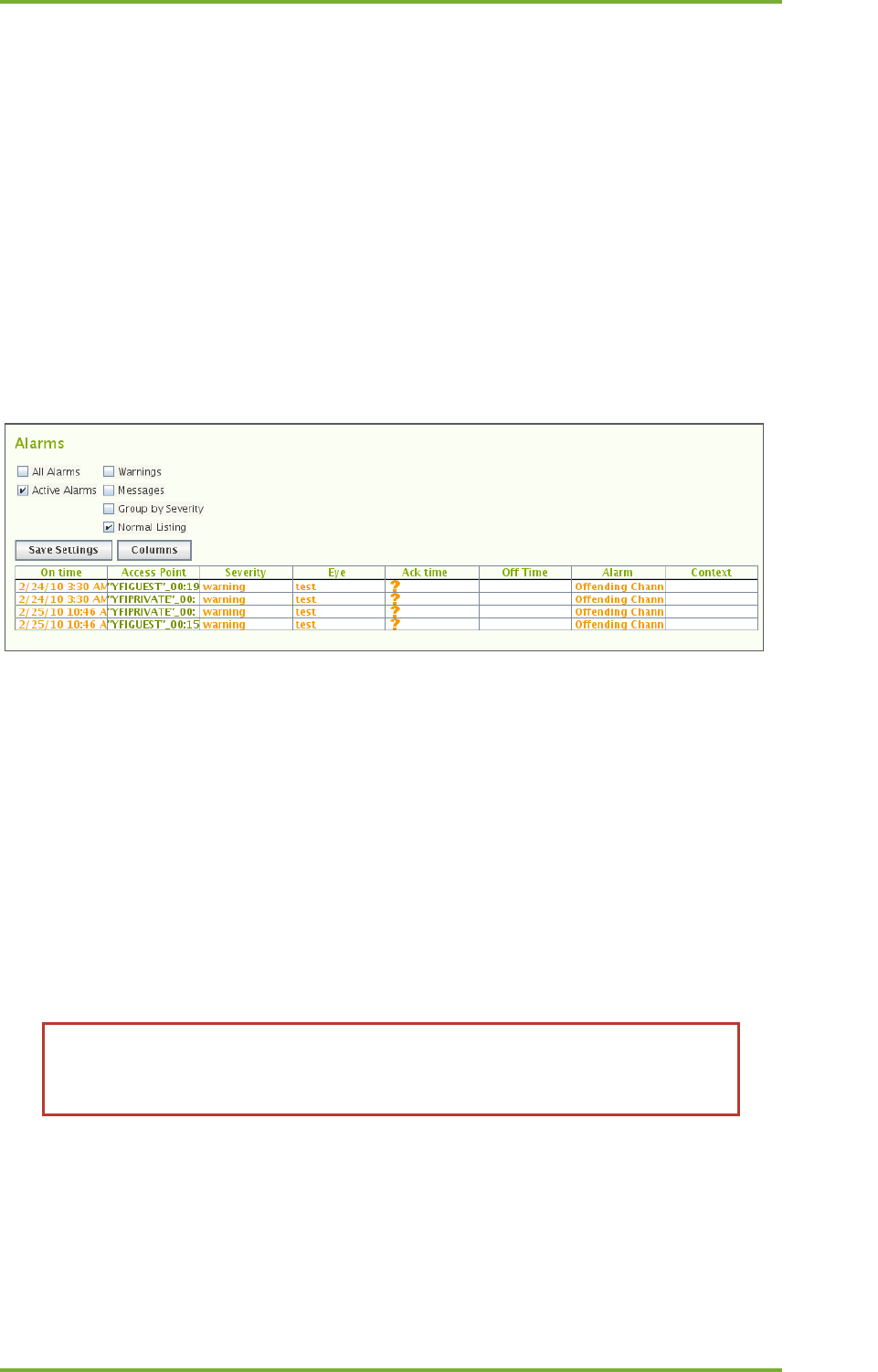
15 Alarms 42
7signal Ltd, Panuntie 6, FI-00620 HELSINKI, FINLAND, +358 40 777 7611, info@7signal.com, www.7signal.com
7signal Sapphire Carat Carat User Guide Release 3.1
2. Select “Bind to alarm limit group”
3. From the pull-down menu, select the alarm group you want to use for this access point
Or
1. Open Service Alarm Binder Dialog by right clicking Service Area Node and selecting
“Bind Alarms”
2. Select Alarm Limit Group from the Combo Box
3. Select Access Points for the binding
4. Save
15.3 Alarm Messages
To view the alarms issued, select “View | Alarms” from the top menu bar. You can indicate
whether you want to see all alarms or only alarms that are currently active. You can also select
how the alarms are listed.
You can acknowledge an alarm by clicking the symbol under “Ack time”. The symbol will be
replaced by the current time of the Carat server, and the alarm is acknowledged. The alarms
are turned off when the cause of the alarm is no longer present.
15.4 Alarm Forwarding
There are two methods that alarms may be brought to attention of external systems: email
forwarding and SNMP.
15.4.1 Email Forwarding
Alarms are sent as plain-text emails with standard formatting easy to be parsed with typical
text-processing tools.
NOTE: Email may be used only for relaying the alarms to the other messaging
system that convert emails to f ex SMS and messenger formats. 7signal products
do not directly provide such integration.
Email forwarding requires an SMTP server to be defined. There may be numerous recipients
that shall receive the alarms.
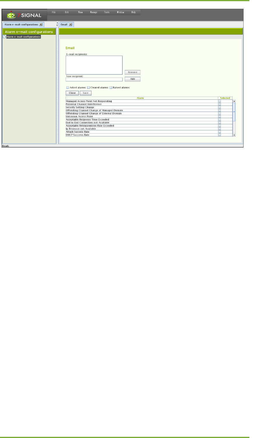
15 Alarms 43
7signal Ltd, Panuntie 6, FI-00620 HELSINKI, FINLAND, +358 40 777 7611, info@7signal.com, www.7signal.com
7signal Sapphire Carat Carat User Guide Release 3.1
1. From the top menu bar, select “Manage | Alarms | Email”
2. Enter target email address to “New recipient” field
3. Select “Add” to register the email address as a recipient. It shall appear in the box
named “Email recipients”
a. Incorrectly added or not any more relevant recipients may be removed by
activating the recipient in the box and then selecting “Remove”
4. Choose the types of alarm event that shall be forwarded by ticking the check-boxes.
a. Types are: raised, acked, offed.
5. Choose the set of alarms to be forwarded by ticking the check-boxes on the alarm
table.
6. Select “Save” the make the selection permanent and stored.
7. Select “Close” to close the pane.
15.4.2 SNMP
Some alarms in Sapphire Carat can be forwarded as SNMP notifications to a receiving server.
1. From the top menu bar, select “Manage | Alarms | SNMP”
2. Enter the IP address of the receiving server
3. Enter the UDP port to use
4. Select the SNMP version (v2c/v3) to be used for the message format
5. If you select v3, you must also:
a. Enter a security name
b. Select the security level (authentication / no authentication)
c. If you select authentication, configure its settings:
i. Select an encryption method (MD5/SHA)
ii. Enter a password
iii. Re-enter the password
6. Select the alarms you want to forward
7. Select the events you want to forward:
a. Alarms issued
b. Acknowledged alarms
c. Alarms that have been turned off
8. Select “Update”
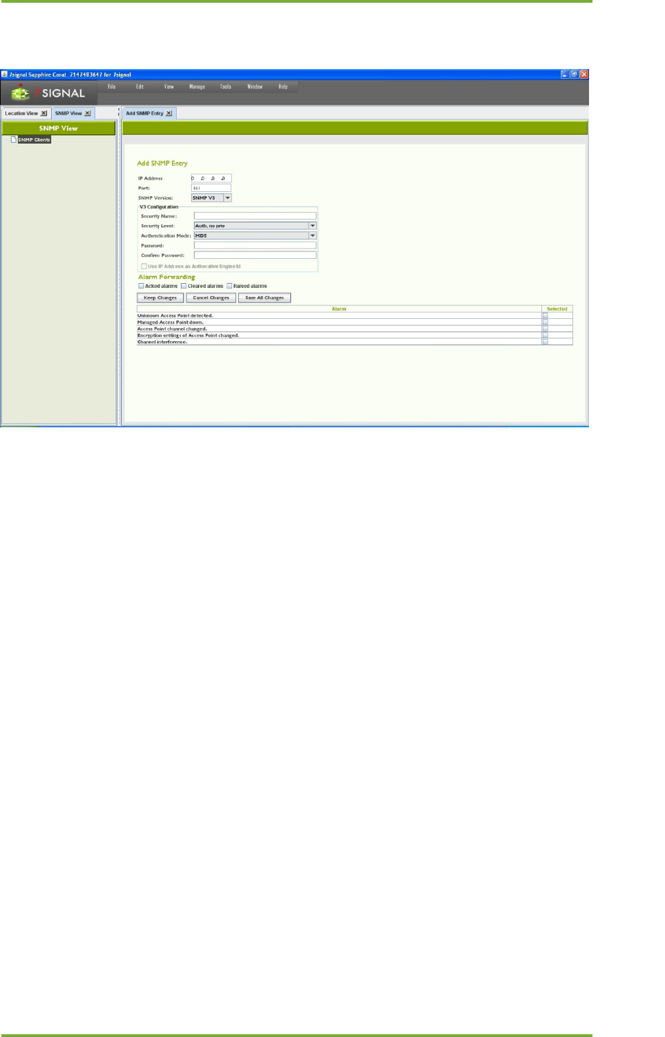
15 Alarms 44
7signal Ltd, Panuntie 6, FI-00620 HELSINKI, FINLAND, +358 40 777 7611, info@7signal.com, www.7signal.com
7signal Sapphire Carat Carat User Guide Release 3.1
9. Click Save all Changes.
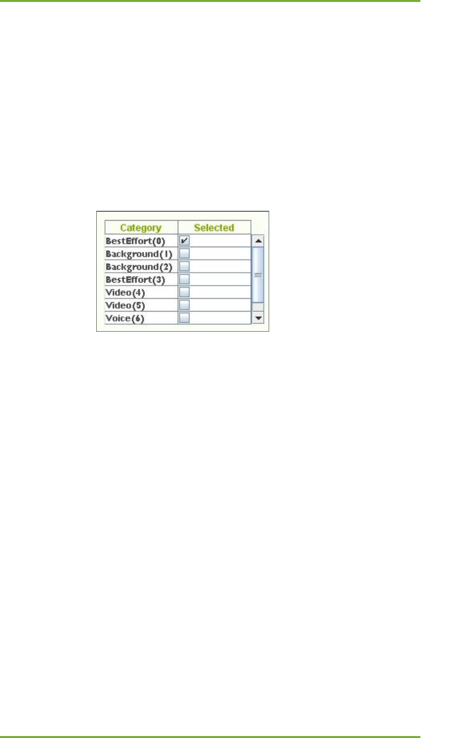
16 Traffic Classes 45
7signal Ltd, Panuntie 6, FI-00620 HELSINKI, FINLAND, +358 40 777 7611, info@7signal.com, www.7signal.com
7signal Sapphire Carat Carat User Guide Release 3.1
16 TRAFFIC CLASSES
The IEEE 802.11e standard defines eight traffic classes. Most mission-critical access points
support this standard. Traffic classes are becoming more and more important, especially on
account of wireless VoIP.
7signal Sapphire Enterprise supports the 802.11e standard. Active tests can be configured to
have a traffic class. All Sapphire versions support assignment of traffic classes, but if the
Sapphire license does not include traffic classes, Sapphire will treat the traffic as ordinary
traffic (Non-QoS, best-effort). Traffic classes are taken into account in only those networks
whose access points support this feature. A request for a traffic class does not guarantee that
it is granted. When viewing measurement reports, you might see that several traffic classes
have been used. The class granted will never exceed that requested.
The following table describes the traffic classes for the parameters of active tests:
The standard defines eight traffic classes, which are grouped into four named classes
(background, best-effort, video, and voice). In practice, most telecommunications devices
support four named classes. This is seen in Sapphire as well, where Eye supports four classes,
and the user interface shows eight. Only supported classes are selectable in the user interface.
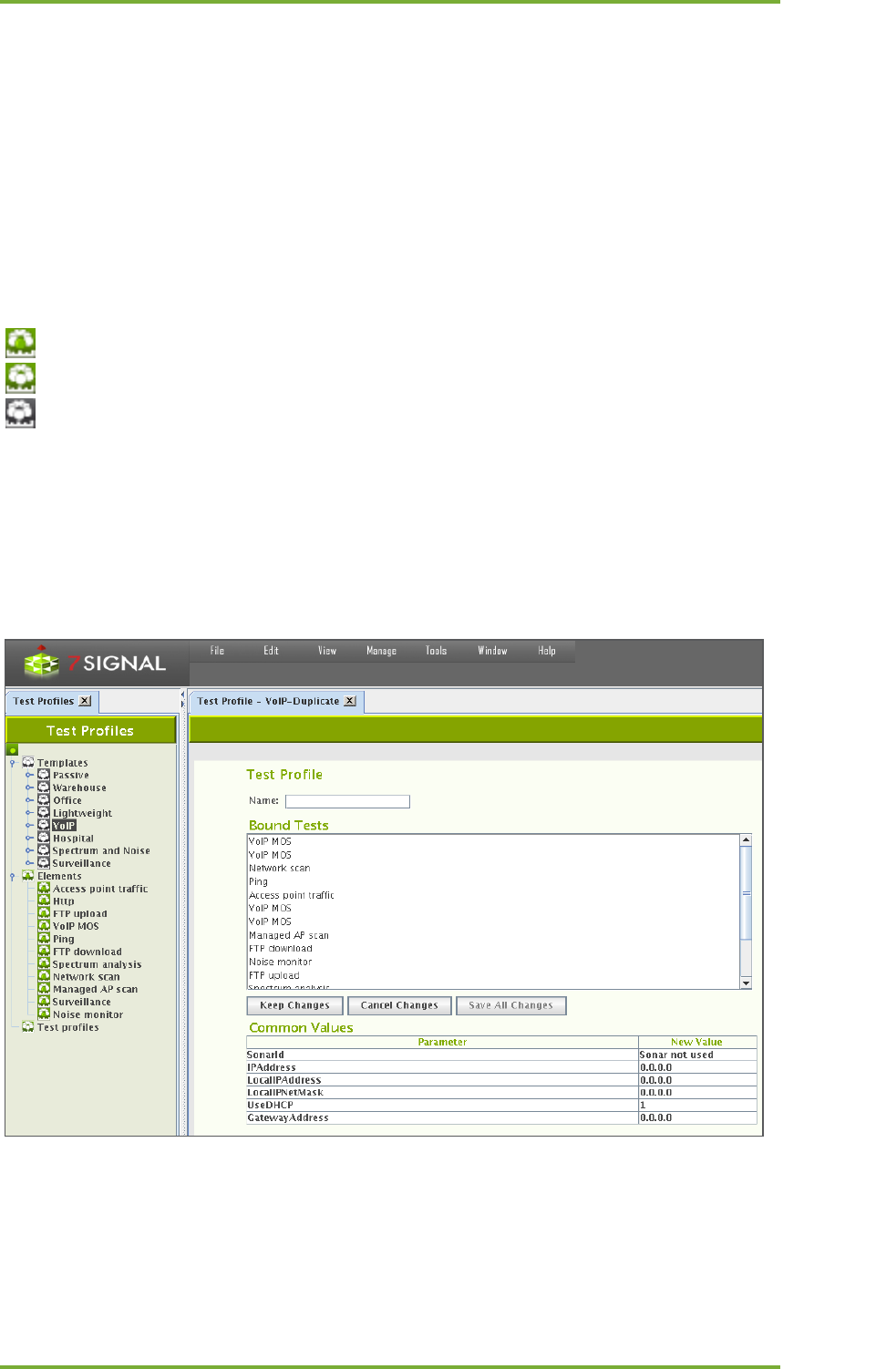
17 Automated test configuration 46
7signal Ltd, Panuntie 6, FI-00620 HELSINKI, FINLAND, +358 40 777 7611, info@7signal.com, www.7signal.com
7signal Sapphire Carat Carat User Guide Release 3.1
17 AUTOMATED TEST CONFIGURATION
The tests are grouped into passive listening tests and active tests in the radio network. There
are two ways to run tests in Sapphire Carat: user-initiated tests to locate a fault and
automated tests for continuous monitoring and collecting of measurement results.
You can run the tests from a hierarchical tree. Test menus are accessible by right-clicking a
monitoring station or an access point. You can also run tests from the floor plan.
17.1 Test Profiles
Related icons
test profile element
test profile
test profile template
A test profile is a series of tests that can be run continuously either on a per-access-point basis
or in monitor mode, thus listening all 802.11 traffic. Sapphire contains preconfigured profiles
intended for typical business environments.
To set up test profiles, select “Manage | Test Profiles” to display the Test Profiles view. The
existing templates, test elements and actual profiles are displayed on the left in the
management tree in descending order, respectively.
Templates are a collection of pre-configured test profiles aimed at various business
purposes. They are not to be used as runnable test profiles but as a source, reference
and model for the user creating the runnable test profiles.
Elements are individual tests that may be inserted to test profiles.
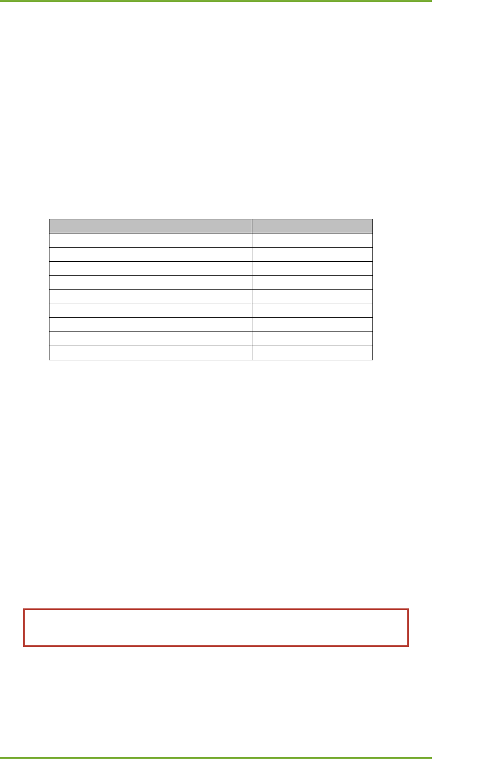
17 Automated test configuration 47
7signal Ltd, Panuntie 6, FI-00620 HELSINKI, FINLAND, +358 40 777 7611, info@7signal.com, www.7signal.com
7signal Sapphire Carat Carat User Guide Release 3.1
Test profile is a collection of test elements that may be executed. The user is supposed
to copy either templates or elements to a test profile. There may be numerous profiles
for different purposes. A test profile is always bound to a monitoring station.
17.2 Contents Of A Test Profile
The purpose of the network dictates which tests should be used to get the best picture of its
functionality. As a result, there are several preconfigured test profiles, where the order and
frequency of tests is different and so are test parameters, such as the number of megabytes
downloaded and uploaded. The test profile names reflect the business environment in which
they are thought to be most useful.
Below is a sample profile that could be used for a monitoring station.
Test
Test parameters
RTT ping
32 B x 10
Download
2 MB x 2
Scan managed
350 ms/channel
Download
2 MB x 2
Access point traffic
60 s
Noise monitor
350 ms/channel
Scan
350 ms/channel
Http
500 kB
MOS
VoIP parameters
When the profile is running, each test is run in its turn, followed by the next test. After the last
test is run, the test profile starts from the beginning. The table shows the most important test
parameters, but the tests also have other configurable parameters.
Below are descriptions of the preconfigured profiles - Templates - in Sapphire. You can copy a
template and save it under a different name. You can then freely modify the parameters in the
original profile and the copy. By copying test profiles, you can easily create a customized
profile for each monitoring station.
17.2.1 Passive
“Passive” template contains five passive tests and no active tests. In passive tests, the
monitoring station does not attach to an access point; it just listens to radio traffic for the
specified time. When using a passive profile, you do not need to configure encryption settings
or authentication for the radio network.
Note: A passive profile has an extremely small effect on the monitored network.
The only effect is that Sapphire sends probe requests to access points.
17.2.2 Warehouse
The “Warehouse” template serves the needs of logistics services where the amount of data
transferred is not large but the data traffic is continuous. Network availability and uptime are

17 Automated test configuration 48
7signal Ltd, Panuntie 6, FI-00620 HELSINKI, FINLAND, +358 40 777 7611, info@7signal.com, www.7signal.com
7signal Sapphire Carat Carat User Guide Release 3.1
vital. The network clients are mostly known or even preconfigured. This profile can be used in
all environments that have similar circumstances.
17.2.3 Office
The “Office” template is intended for office use wherein the clients are mostly laptops running
office applications. An office WLAN must have superb usability and a robust data transfer
capacity. This profile can be used in all environments with similar circumstances.
17.2.4 Lightweight
The “Lightweight” profile is intended for environments that do not have several concurrent
users and that have a narrowband link to a central server (<512 kbit/s). This profile emphasizes
WLAN availability. Another emphasis is on a fast testing cycle, where each test takes only a
short time.
17.2.5 VoIP
The “VoIP” template is intended for environments where the wireless clients are mostly VoIP
devices. A wireless VoIP network must have extremely high-quality radio connections. The
MOS test indicates packet losses and jitter in the network, among other things.
17.2.6 Hospital
“Hospital” resembles the “Office” template. However, the “Hospital” template produces more
results that describe the status of the wireless clients. The profile is a general purpose one that
emphasizes wireless clients.
17.2.7 Spectrum and Noise
This template is limited in test elements: there are no active test at all. It is targeted for
environments that have severe interference conditions. This can be considered as a trouble-
shooting template that is activated if the normal course of testing does not provide enough
information on the source of the interference.
17.2.8 Surveillance
The “Surveillance” is a limited template with one test only that specializes in surveillance. The
point is to capture traffic in any channel in any direction. The rationale is environments where
there should be no radio traffic at all or only for white-listed devices.
17.2.9 TripleSSID
Mainly example how to configure test profiles that access numerous wlan networks in a single
profile. This is the case one Eye unit is supposed to monitor multiple wlans concurrently. The
next chapter has more details on this.
17.3 Testing multiple wlan networks in one test profile
One monitoring station may test multiple access points that provide multiple wlan networks.
In the context of test profiles wlan networks are referred as ESSIDs (essid later in the text).

17 Automated test configuration 49
7signal Ltd, Panuntie 6, FI-00620 HELSINKI, FINLAND, +358 40 777 7611, info@7signal.com, www.7signal.com
7signal Sapphire Carat Carat User Guide Release 3.1
Testing on multiple essid’s is achieved by either copying and editing individual test element in
a profile or copying a complete template to pasted to an existing profile.
Whenever it is possible to define an essid to a test element there may be exactly one essid per
element or no essid at all. The latter means that the test in question shall be executed against
all access points managed by the monitoring station. The former limits the access points to
ones that have the essid and are managed by the monitoring station.
17.4 Operations on Templates
Templates are for copying and editing. There are two different supported methods for that,
“Duplicate” to make a fresh copy of the sample profile and “Copy as essid” that adds the
template profile to an existing test profile.
17.4.1 Duplicate
1. Select “Manage | Test Profiles” to open the management tree on the left.
2. Choose the appropriate template and right-click for the submenu.
3. Select “Duplicate” to open the Test Profile pane.
4. Give a name to the new Test Profile.
5. Bound Tests window is for informative purposes here only. Editing if desired is
available later.
6. In “Common Values” one may enter test parameters that apply to every test in the
profile.
7. Saving options
a. Select “Cancel Changes” to undo changes.
b. Select “Keep Changes to save the intermediate work.
c. Select “Save All Changes” to finalize the work on this pane.
17.4.2 Copy as essid
The pre-requisite here is to have existing test profiles that shall be the target for pasting all
elements in the template. This is one form of cut&paste operation.
1. Select “Manage | Test Profiles” to open the management tree on the left
2. Choose the appropriate template and right-click for the submenu
3. Select “Copy as essid” (no visible results)
4. Right-click on Test Profile icon and select “Insert essid” to open essid pane on the right
5. Insert an existing essid name
6. Optionally, insert other common parameters in the table “Common Values”
7. Select “Save All Changes” to insert the test elements in the template to the test profile
as individual essid. All tests under the essid contain the same parameters, such as
Sonar etc.
17.5 Operation on Test Element
17.5.1 Copy element
The pre-requisite here is to have existing test profiles that shall be the target for pasting this
test element. This is one form of cut&paste operation.
1. Select “Manage | Test Profiles” to open the management tree on the left

17 Automated test configuration 50
7signal Ltd, Panuntie 6, FI-00620 HELSINKI, FINLAND, +358 40 777 7611, info@7signal.com, www.7signal.com
7signal Sapphire Carat Carat User Guide Release 3.1
2. Choose one of the test elements and right-click
3. Select “Copy element” (no visible results)
4. Paste the element by choosing “Paste testprofile element” available on the right-click
a. If the target is a Test Profile icon, the element shall be the last one in that
profile
b. If the target is an essid inside a test profile, the element shall be the last one
for that essid.
5. Repeat step 2-4 until the test profile is according the expectations.
17.6 Operations on Test Profile Node
Save All Changes
Any change in the sub-tree shall be made persistent.
Add empty Test Profile
A new test profile object to the tree shall be inserted. The only input required is the name of
the profile.
17.7 Operations on Test Profile
Edit
Open a pane with “Common Values” and “Name” field ready for editing. “Bound Tests”
remains read-only, the elements are managed in the tree.
Duplicate
Create identical test profile with a new name. It is possible to change top-level parameters on
the same pane. This option enables easy creation of test profiles with similar test elements to
another link.
Copy as essid
Copies the contents of a test profile to be pasted to another profile as essid object.
Remove
Removes the object.
Bound Eyes
Shows the monitoring stations that are using this profile.
Paste test profile element
Paste previously copied test profile element as the last element in the profile.

17 Automated test configuration 51
7signal Ltd, Panuntie 6, FI-00620 HELSINKI, FINLAND, +358 40 777 7611, info@7signal.com, www.7signal.com
7signal Sapphire Carat Carat User Guide Release 3.1
Save
Make the changes in the sub-objects persistent.
Insert Essid
Paste previously copied essid into this profile as the last element.
Insert New Essid
Create a new empty essid into this profile as the last element.
17.8 Operations on essid inside a test profile
Edit
Open a pane with “Common Values” and “Name” field ready for editing.
Copy
Enable pasting of the object.
Paste test profile element
Paste previously copied test profile element as the last element in the profile.
Remove
Deletes the object.
17.9 On test elements
Each test has default parameters, which can be used as is or modified as needed. To obtain the
best results and find the best measurement methods for a target network, plan and configure
the tests to suit the network.
A test profile must be configured for each monitoring station separately. The same profile can
be used in several monitoring stations.
17.9.1 Modifying test parameters
If you wish to modify individual tests, see the instructions below. For each test, do the
following:
1. Select the test from the profile and right-click the test
2. Select “Edit”
3. If desired, set the test duration (in seconds)
a. The test duration does not affect the running of the test; however, if the test
type is temporarily removed from the test set, the time specified is spent in
sleep mode, depending on the configuration
4. For some tests, such as RTT ping, you may also do the following:
a. Select the interval, or the pause between pings
b. Select Sonar

17 Automated test configuration 52
7signal Ltd, Panuntie 6, FI-00620 HELSINKI, FINLAND, +358 40 777 7611, info@7signal.com, www.7signal.com
7signal Sapphire Carat Carat User Guide Release 3.1
c. Select an access point
d. Select an IP address
e. Select the number of bytes to be downloaded/uploaded
f. Select the number of repetitions
g. Select the client’s IP address policy:
i. DHCP in use (1)
ii. Static address (0) – enter address data
5. Select “Keep changes”
6. Select “Save all changes”
17.9.2 Use case: Multiple SSID testing
There are two ways to achieve testing on multiple networks on one single monitoring station.
The first is based on element copying (the previous paragraph) and the other is using copies of
essid objects.
Using copies of elements may be burdensome at the configuration time but gives control over
the test order. By copying one single element (test type) to be sequentially tested on different
wlans produces the following sample profile:
1. FTP on Wlan1
2. FTP on Wlan2
3. FTP on Wlan3
4. Spectrum
5. MOS on Wlan1
6. MOS on Wlan2
7. MOS on Wlan3
8. Scan
The other approach is the create a simple test sequence as essid and then duplicate the essid
object and make the duplicates to point to different wlans. The resulting sample test profile
would be similar to the following:
1. FTP on Wlan1
2. MOS on Wlan1
3. Spectrum
4. FTP on Wlan2
5. MOS on Wlan2
6. Scan
7. FTP on Wlan3
8. MOS on Wlan3
Please observe that in the latter approach the measurements on a single wlan network shall
be sparser temporally. While individual tests shall happen on roughly the same time interval,
the distribution of the samples per network differs a great deal on these two approaches.
When planning the test cycles, one should bear in mind:
• The more tests there are in the sequence, the bigger the difference in sample
distribution.
• The more networks, the less samples for individual networks.
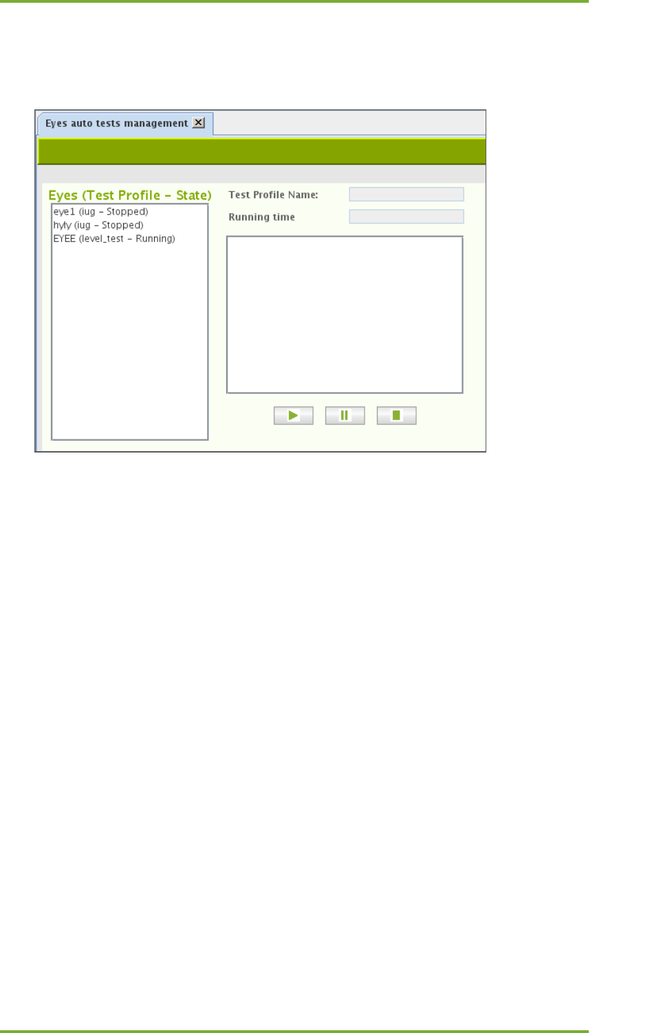
17 Automated test configuration 53
7signal Ltd, Panuntie 6, FI-00620 HELSINKI, FINLAND, +358 40 777 7611, info@7signal.com, www.7signal.com
7signal Sapphire Carat Carat User Guide Release 3.1
17.10 Running test profiles
Select “Tools | Eye auto tests management” to see current status of Eye units.
The Eyes of the user context are enlisted in the box on the right. The Eye name, the test profile
name and the state of the test profile run are indicated.
By selecting one of the Eyes brings additional information such as the run time and test profile
content on the left.
Buttons:
Play – runs the chosen test profile on the active Eye
Pause – temporarily stop or resume running the test profile on the active Eye
Stop – Stop running the profile on the active Eye
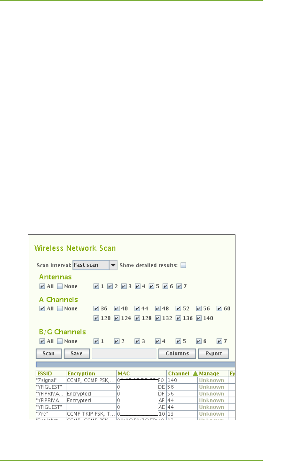
18 Manual tests 54
7signal Ltd, Panuntie 6, FI-00620 HELSINKI, FINLAND, +358 40 777 7611, info@7signal.com, www.7signal.com
7signal Sapphire Carat Carat User Guide Release 3.1
18 MANUAL TESTS
Manual tests can run simultaneously with automated testing. Sapphire will perform ongoing
automated test first and then run user defined manual test. Automated test will continue after
manual test has been finished.
Manual test results will not be saved to database.
18.1 “Network Scan” test
The network scan test can also be used as a separate test outside initial deployment. The
deployment is described in the previous section of this guide.
To scan the network, do the following:
1. In the Network topology, select the Eye you want to use for scanning the network
2. Right-click and select “Network Scan”; a test window is displayed in the right pane
3. Select the test duration from the pull-down menu
4. If you want to view information about each antenna, select “Show RX level”
a. If this checkbox is selected, the results window has a separate line for each
antenna, which might make the window’s content more difficult to read
b. The system selects the best antenna automatically in any case
c. The system offers an active test for verification of the antenna selection
5. Select the scan directions – i.e., directional antennas
6. Select the channels to scan
7. Select “Scan”
8. The results are displayed in a table
MAC
hidden

18 Manual tests 55
7signal Ltd, Panuntie 6, FI-00620 HELSINKI, FINLAND, +358 40 777 7611, info@7signal.com, www.7signal.com
7signal Sapphire Carat Carat User Guide Release 3.1
After the network scan, you can verify the suitability of the selected antenna by
running the antenna selection test.
The information in the table can be edited. Remember to save the changes.
• “Manage”: The management status: the status of a monitoring station can be changed
• “Sel Ant”: Selected antenna – you can change the antenna used by the Eye to monitor
the access point
o We recommend that you compare the signal levels received very thoroughly
o We recommend that you perform the antenna selection test if anything is
even slightly unclear
Options for processing the results:
• “Save” saves the information in the table to the Carat system.
• “Columns” select the visible columns; the table might be easier to read if you hide
unnecessary columns
• “Export” exports a text file to the local file system – you can enter the location in the
dialog that appears after you click “Export” – which is a handy feature for comparison
of results obtained at different times
18.2 “Client scan” test
You can scan for preconfigured clients by their MAC address.
1. In the Network topology, select the Eye you want to use for scanning the network
2. Right-click and select “Active Tests | Client Scan”
3. Enter the scan duration under “Scan interval”
4. Select the scan directions – i.e., antenna lobes
5. Select the channels to scan
6. Select “Scan”
7. The results are displayed in a table:
a. The MAC address of the scanned devices that transmitted during the test
b. The noise level and signal strength, by antenna
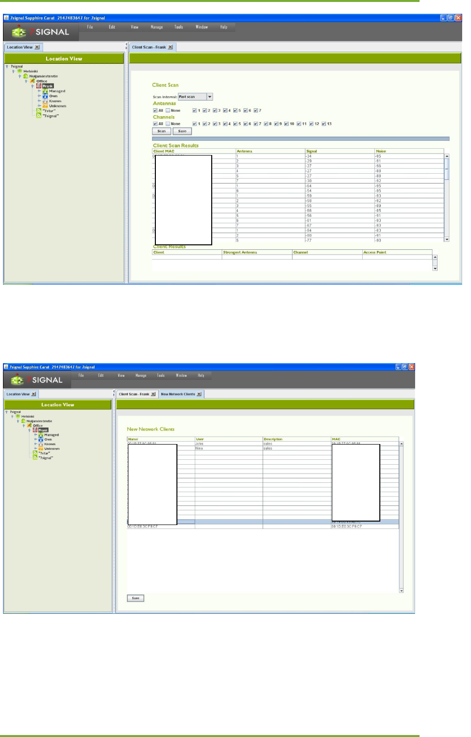
18 Manual tests 56
7signal Ltd, Panuntie 6, FI-00620 HELSINKI, FINLAND, +358 40 777 7611, info@7signal.com, www.7signal.com
7signal Sapphire Carat Carat User Guide Release 3.1
8. Select “Save”; the clients detected remain in the table
9. You can enter a friendly name and description for each user; this name will be
displayed in future results instead of the MAC address
10. Select “Save” to save the friendly names and descriptions
The data can be viewed and edited.
1. From the top menu bar, select “Manage | Network clients”
2. To change the information, select the MAC address or name
MAC
hidden
MAC
hidden
MAC
hidden
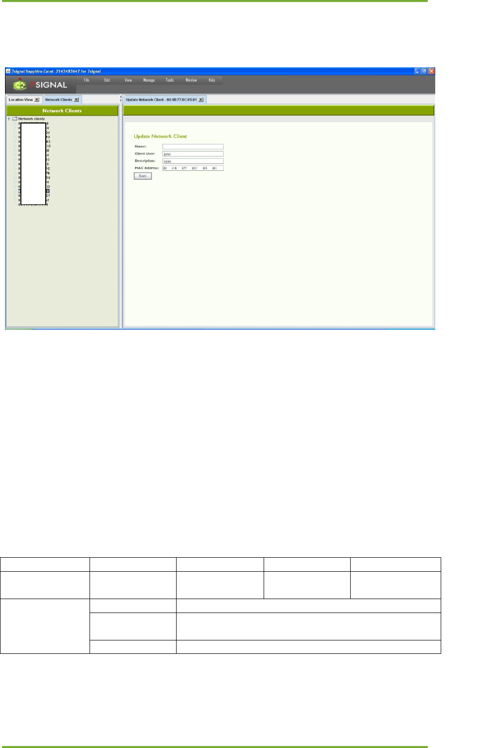
18 Manual tests 57
7signal Ltd, Panuntie 6, FI-00620 HELSINKI, FINLAND, +358 40 777 7611, info@7signal.com, www.7signal.com
7signal Sapphire Carat Carat User Guide Release 3.1
3. Right-click and select “Edit”
4. Edit the information
5. Select “Save”
18.2.1 Addition of a new client
1. From the top menu bar, select “Manage | Network clients”
2. In the hierarchical tree in the left pane, right-click the topmost element, titled
“Network clients”
3. Select “Add network client”
4. Enter a friendly name for the client
5. Enter a user’s name, if known
6. Enter a description (optional)
7. Enter the client’s MAC address
8. Click “Save”
To add several clients at once, select “Import network clients” in step 3. This option imports a
text file from the Carat server’s file system. The file format is as follows:
field
MAC
Name
User
Description
explanation
MAC address,
required
Client name,
(optional)
Client user if
known (optional)
Client description
(optional)
example
complete
A:B:C:D,pda,Pda User,personal digital assistant
description
omitted
A:B:C:D,officeLaptop,J.D.,
partial
A:B:C:D,barCodeReader, ,
The “Export network clients” function creates a corresponding file in the Carat server’s file
system.
MAC
hid-
den
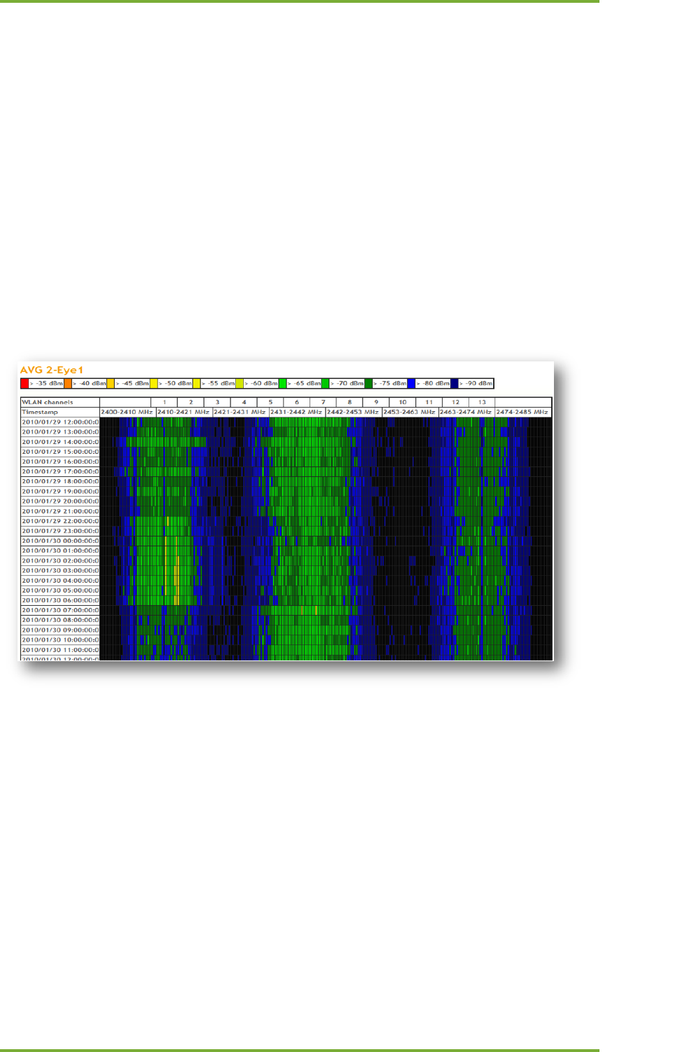
18 Manual tests 58
7signal Ltd, Panuntie 6, FI-00620 HELSINKI, FINLAND, +358 40 777 7611, info@7signal.com, www.7signal.com
7signal Sapphire Carat Carat User Guide Release 3.1
18.3 Spectrum Analyzer
The monitoring station supports frequency-sweep-based radio spectrum analysis. The
frequency status is displayed as a colored map.
1. In the Network topology, select the Eye that will run the test
2. Right-click and select “Spectrum Analysis”
3. Select a suitable sweep method from the pull-down menu
4. Select the presentation mode from the pull-down menu
a. Off-line: one-time draw
b. On-line: regularly updated image
5. Select the test duration from the pull-down menu
6. Select the antennas to be used in the test by selecting their respective checkboxes
7. Select “Scan”
For the results See the figure below:
18.4 “Noise monitor” test
You can measure the noise levels surrounding the monitoring station.
1. In the Network topology, select the Eye that will run the test
2. Right-click and select “Noise Monitor”
3. Select the scan directions – i.e., directional antennas
4. Select the channels to scan
5. Select “Execute”
6. The results are displayed in a table as seen below
7. To view the results in a graphical view, click “Show graph”
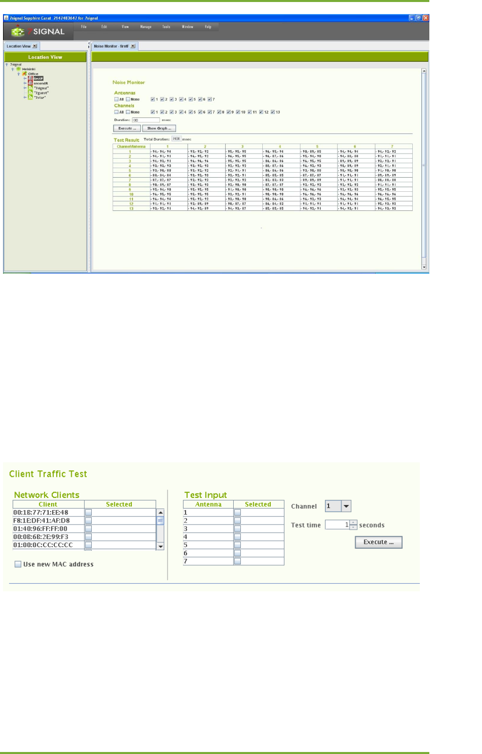
18 Manual tests 59
7signal Ltd, Panuntie 6, FI-00620 HELSINKI, FINLAND, +358 40 777 7611, info@7signal.com, www.7signal.com
7signal Sapphire Carat Carat User Guide Release 3.1
18.5 “Client Traffic Test”
This test listens to radio traffic in the Sapphire Eye’s coverage area and gathers information on
wlan clients that are active i.e. exchange traffic with access points in the proximity.
The result contains all the clients that were active during the test. Please note that both
channels and antennas work in an exclusive manner, only one antenna and only one channel
are active at the time. In other words: it is impossible to capture all the traffic during the test
execution.
Depending on the test purpose, it might be worthwhile to define the interesting MAC
addresses beforehand, possibly giving a friendly-name, too. If such definition exists, the
friendly-name is shown in the result tables instead of text-formatted MAC addresses.
To run the test:
1. In the Network topology, select the Eye that will run the test
2. Right-click and select ”Manual tests | Client Traffic Test”
3. Select the antennas to be used in the test
4. Select the channel to be used in the test
5. Select the listening time from the drop-down menu, the division is similar to the
network scan
6. Select “Execute”
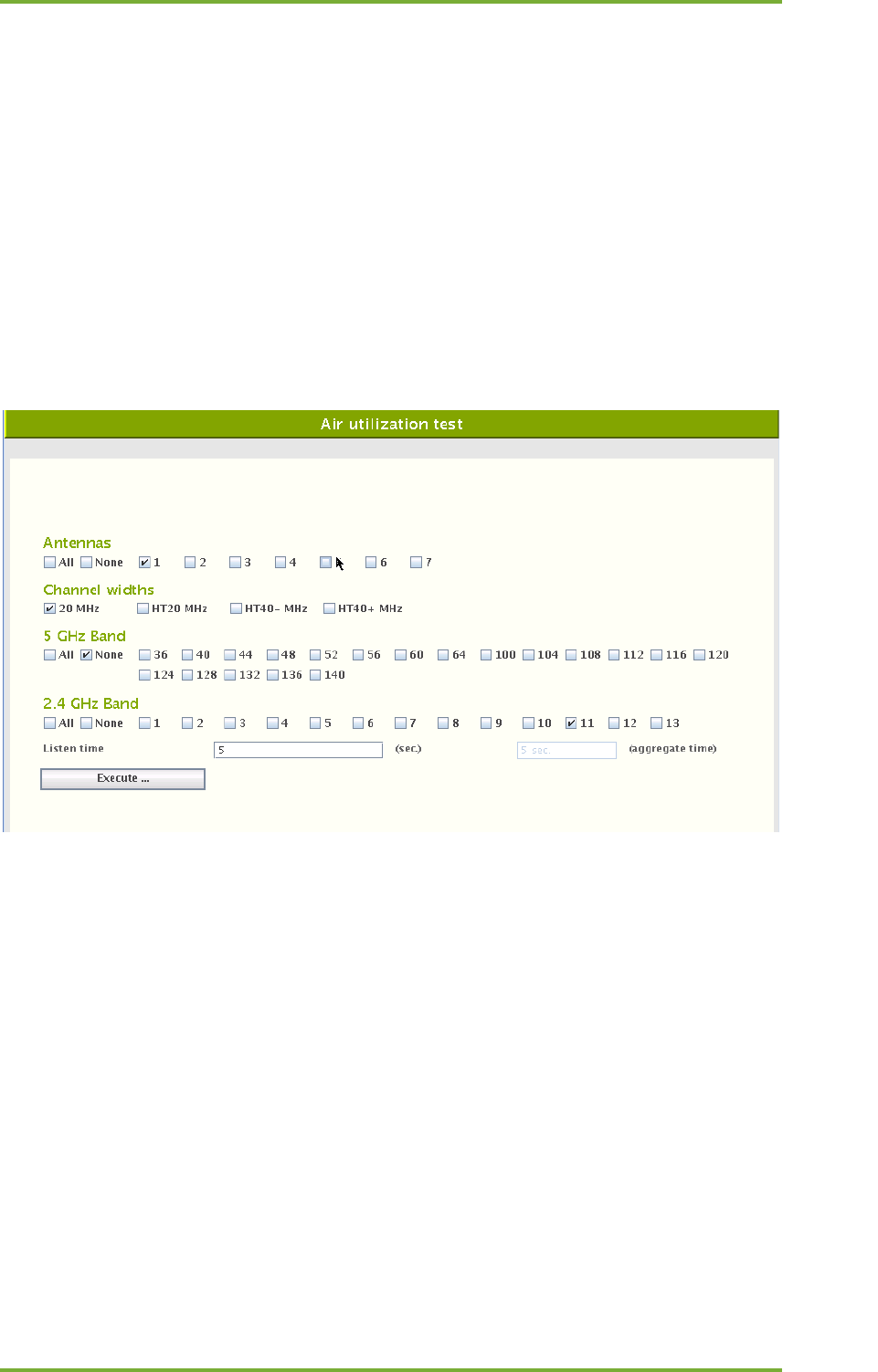
18 Manual tests 60
7signal Ltd, Panuntie 6, FI-00620 HELSINKI, FINLAND, +358 40 777 7611, info@7signal.com, www.7signal.com
7signal Sapphire Carat Carat User Guide Release 3.1
The results are displayed in two tables as seen below. The tables are active and the column
names support sort-orders.
The table “Client Scan Results” shows individual clients and their antenna sectors. By activating
a row on this table, more detailed information on the client is displayed on the table named
“Client Results” below.
18.6 “Air Utilization” test
To capture spectrum heavy-users and misconfigurations – such as extensive use of legacy
codecs - in the wlan network, air utilization test should be run. This test is not part of the test
profiles as it is lengthy troubleshoot test. Special attention to the test parameters is required
as the maximum runtime is easily very high. One should check the “aggregate time” box for an
estimate.
To run the test:
1. Select antennas, at least one must be selected.
2. Select the desired channels with the check-boxes.
3. Select the channel widths for the test(802.11n feature)
4. Select the time – in seconds – to listen to each selected channel on each selected
antenna.
The results are shown in a table that has each antenna/channel combination as one row. One
will get simple table result by activating each row with the mouse. There shall be more
detailed result if “Show graph” is selected for the activated row:
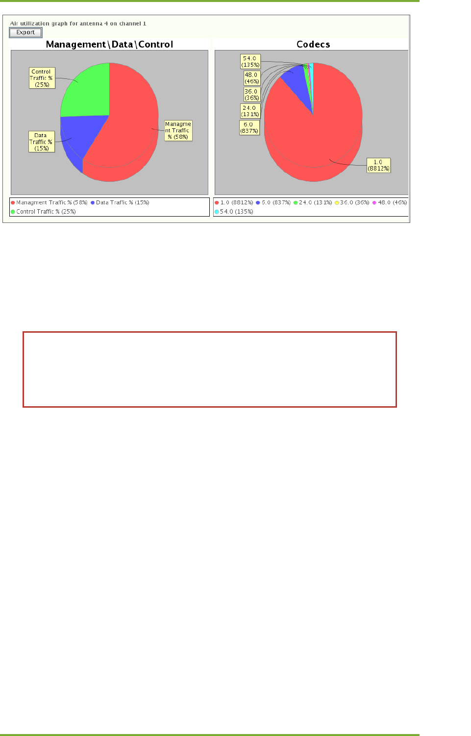
18 Manual tests 61
7signal Ltd, Panuntie 6, FI-00620 HELSINKI, FINLAND, +358 40 777 7611, info@7signal.com, www.7signal.com
7signal Sapphire Carat Carat User Guide Release 3.1
Antenna/channel row is presented in a pie-chart form that show frame type distribution on
the left and codec distribution on the right.
18.7 “Optimal Antenna Selection” test
The antenna test is used to verify the suitability of the selected antenna. Because
of reflections, the network scan can show similar results for different antennas.
However, during transmission of data to an access point, the differences between
antennas become significant. This test is worth running if more than one antenna
shows similar results.
1. In the Network topology, select the Eye that will run the test
2. Right-click and select “Active Tests | Optimal Antenna Selection”
3. Select the Sonar against which you want to run the test, or type another IP address
4. Select an access point
5. Select the Eye’s IP address (DHCP or static)
a. If static, enter the (1) local IP address, (2) local netmask, and (3) gateway
6. Set up the test options:
a. Select the amount of data transferred at one time
b. Select the antennas to be used in the test
7. Select “Execute”
8. The results are displayed in a table as seen below
9. If an antenna gives better results than the currently used antenna, select the better
antenna for monitoring
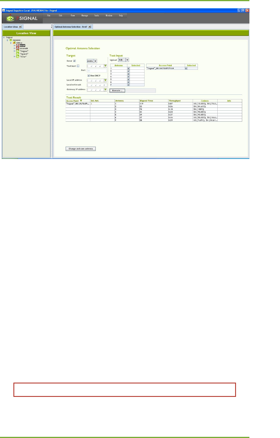
18 Manual tests 62
7signal Ltd, Panuntie 6, FI-00620 HELSINKI, FINLAND, +358 40 777 7611, info@7signal.com, www.7signal.com
7signal Sapphire Carat Carat User Guide Release 3.1
18.8 Download Tests
This test gives an indication of an access point’s FTP or UDP downlink capacity.
1. In the Network topology, select the Eye that will run the test
2. Right-click and select ”Manual tests”
3. From the submenu select either “FTP Download Test” or “UDP Download Test”
4. Specify whether you want to run the test against a Sonar or another target
5. Select the Sonar against which you want to run the test, or type another IP address
6. Select an access point
7. Select the Eye’s IP address (DHCP or static)
a. If static, enter the (1) local IP address, (2) local netmask, and (3) gateway
8. Set up the test options
a. Select the amount of data transferred at one time
b. (UDP only): Packet size to be used (small = 256, medium = 1024, large = 32768
bytes)
c. (UDP only): Sender (Sonar) port. Default 0 means that system shall allocate
used ports. User-given port overrides this setting. Please observe possible
firewall settings.
d. (UDP only): Receiver (Eye) port. Default 0 means that system will allocate used
ports. User-given port overrides this setting. Please observe possible firewall
settings.
e. Select the display format for the results
f. Select how many times the test is to be run
9. Select “Execute”
10. The results are displayed in a table as shown below
You can change the table type even after the test is executed.
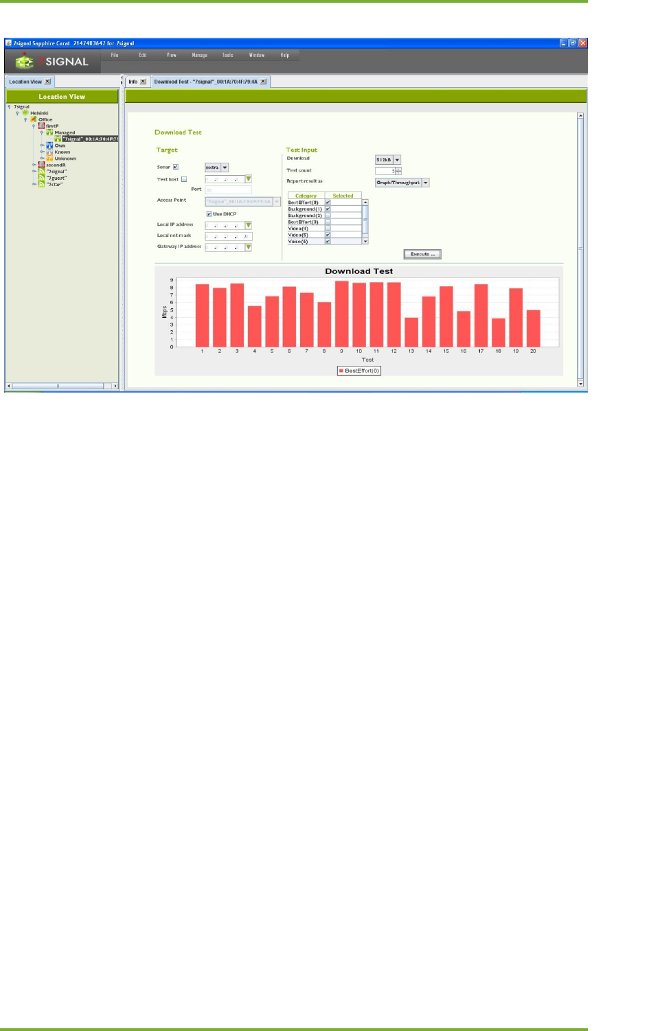
18 Manual tests 63
7signal Ltd, Panuntie 6, FI-00620 HELSINKI, FINLAND, +358 40 777 7611, info@7signal.com, www.7signal.com
7signal Sapphire Carat Carat User Guide Release 3.1
18.9 Upload Tests
This test gives an indication of an access point’s FTP uplink capacity.
1. In the Network topology, select the Eye that will run the test
2. Right-click and select ”Manual tests”
3. From the submenu select either “FTP Upload Test” or “UDP Upload Test”
4. Configure the test target in the target area:
a. Select the Sonar against which you want to run the test, or type another IP
address
b. Select an access point from the pull-down menu
c. Select the Eye’s IP address (DHCP or static)
i. If static, enter the (1) local IP address, (2) local netmask, and (3)
gateway
5. Set up the test options:
a. Select the amount of data from the pull-down menu
b. (UDP only): Packet size to be used (small = 256, medium = 1024, large = 32768
bytes)
c. (UDP only): Sender (Eye) port. Default 0 means that system will allocate ports
.User-given port overrides this setting. Please observe possible firewall
settings.
d. (UDP only): Receiver (Sonar) port. Default 0 means that system shall allocate
used ports. User-given port overrides this setting. Please observe possible
firewall settings.
e. Specify how many times the test is to be run
f. Select the display format for the results from the pull-down menus
g. Select the traffic classes to use (licensed products only)
6. Select “Execute”
The results are displayed in a table as seen below.
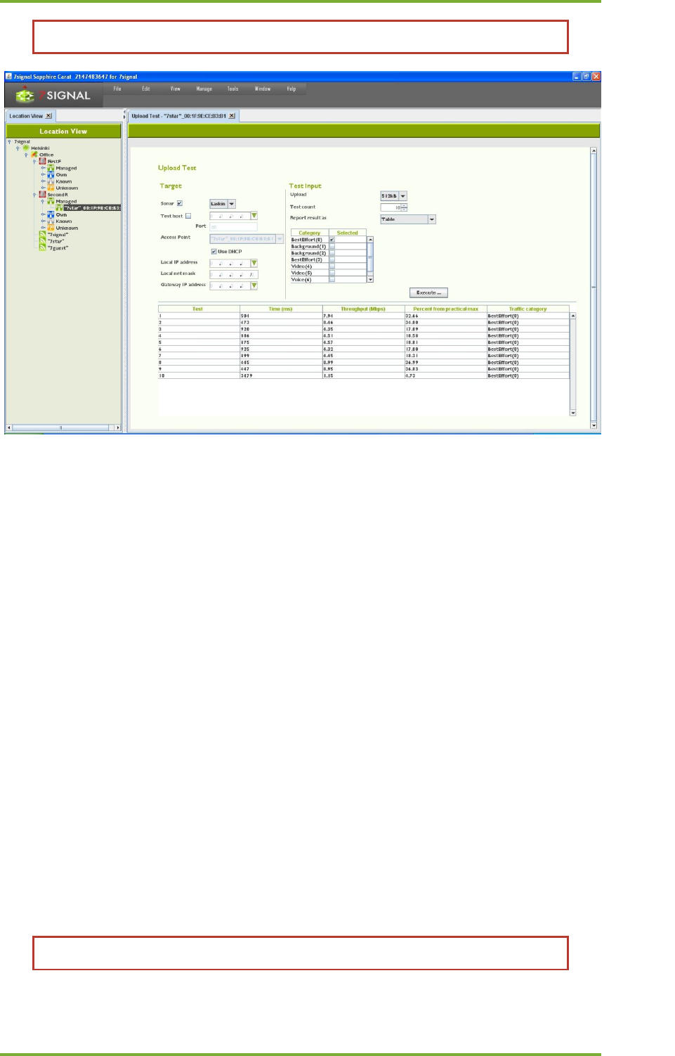
18 Manual tests 64
7signal Ltd, Panuntie 6, FI-00620 HELSINKI, FINLAND, +358 40 777 7611, info@7signal.com, www.7signal.com
7signal Sapphire Carat Carat User Guide Release 3.1
You can change the table type even after the test is executed.
18.10 “Ping” test
A ping test tests the accessibility of a device, the number of packets sent and received, and
latency time.
1. In the Network topology, select the Eye that will run the test
2. Right-click and select ”Manual tests | Ping test”
3. Define the test target in the target area:
a. Select the Sonar against which you want to run the test, or type another IP
address
b. Select an access point from the pull-down menu
c. Select the Eye’s IP address (DHCP or static)
i. If static, enter the (1) local IP address, (2) local netmask, and (3)
gateway
4. Set up the test options:
a. Select the size for the ping packet
b. Select the waiting time between ping tests (in milliseconds)
c. Select the waiting time (in seconds) before termination of a test that does not
progress
d. Specify how many pings will be send.
e. Select the display format for the results from the pull-down menus
5. Select the traffic classes to use (licensed products only) – note that it is not
recommended to use traffic classes in a ping test
6. Select “Execute”
The results are displayed in a report as seen below.
You can change the table type even after the test is executed.
18 Manual tests 65
7signal Ltd, Panuntie 6, FI-00620 HELSINKI, FINLAND, +358 40 777 7611, info@7signal.com, www.7signal.com
7signal Sapphire Carat Carat User Guide Release 3.1
18.11 Traceroute Test
This test helps one perform network troubleshooting and identify routing problems or
firewalls that may be blocking access to a host.
1. In the Network topology, select the Eye that will run the test
2. Right-click and select ”Manual tests | Traceroute Test”
3. Define the test target in the target area:
a. Select the Sonar against which you want to run the test, or type another IP
address
b. Select an access point from the pull-down menu
c. Select the Eye’s IP address (DHCP or static)
i. If static, enter the (1) local IP address, (2) local netmask, and (3)
gateway
4. Set up the test options:
a. Minimum TTL: minimum number of devices/hops to try
b. Maximum TTL: maximum number of devices/hops to try
c. Queries per hop: how many times a device/hop is tried
d. Timeout: how long to wait before giving up on a device/hop
5. Select the traffic classes to use (licensed products only)
6. Select “Execute”
The results are displayed in a report as seen below.
Note: You can change the report type even after the test is executed
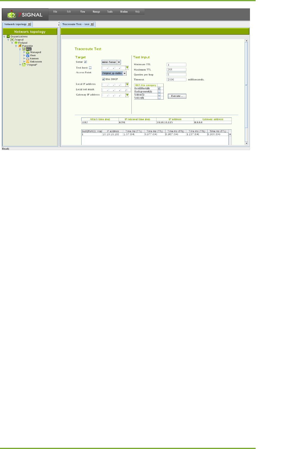
18 Manual tests 66
7signal Ltd, Panuntie 6, FI-00620 HELSINKI, FINLAND, +358 40 777 7611, info@7signal.com, www.7signal.com
7signal Sapphire Carat Carat User Guide Release 3.1
18.12 “Access point traffic” test
This test listens to radio traffic in the Sapphire Eye’s coverage area and gathers many kinds of
information.
1. In the Network topology, select the Eye that will run the test
2. Right-click and select ”Manual tests | Access Point Traffic Test”
Note: This test is among the active tests since it requires you to select a target access
point
3. Select the target access points from the table
4. Select the listening time (in milliseconds)
5. Select “Execute”
The results are displayed in a table as seen below – the tree view in the table shows the access
point as the root node, and the heard clients under it; for more information, move the mouse
cursor over the individual items in the tree or, to display even more details and a graphical
view, click an item in the tree.
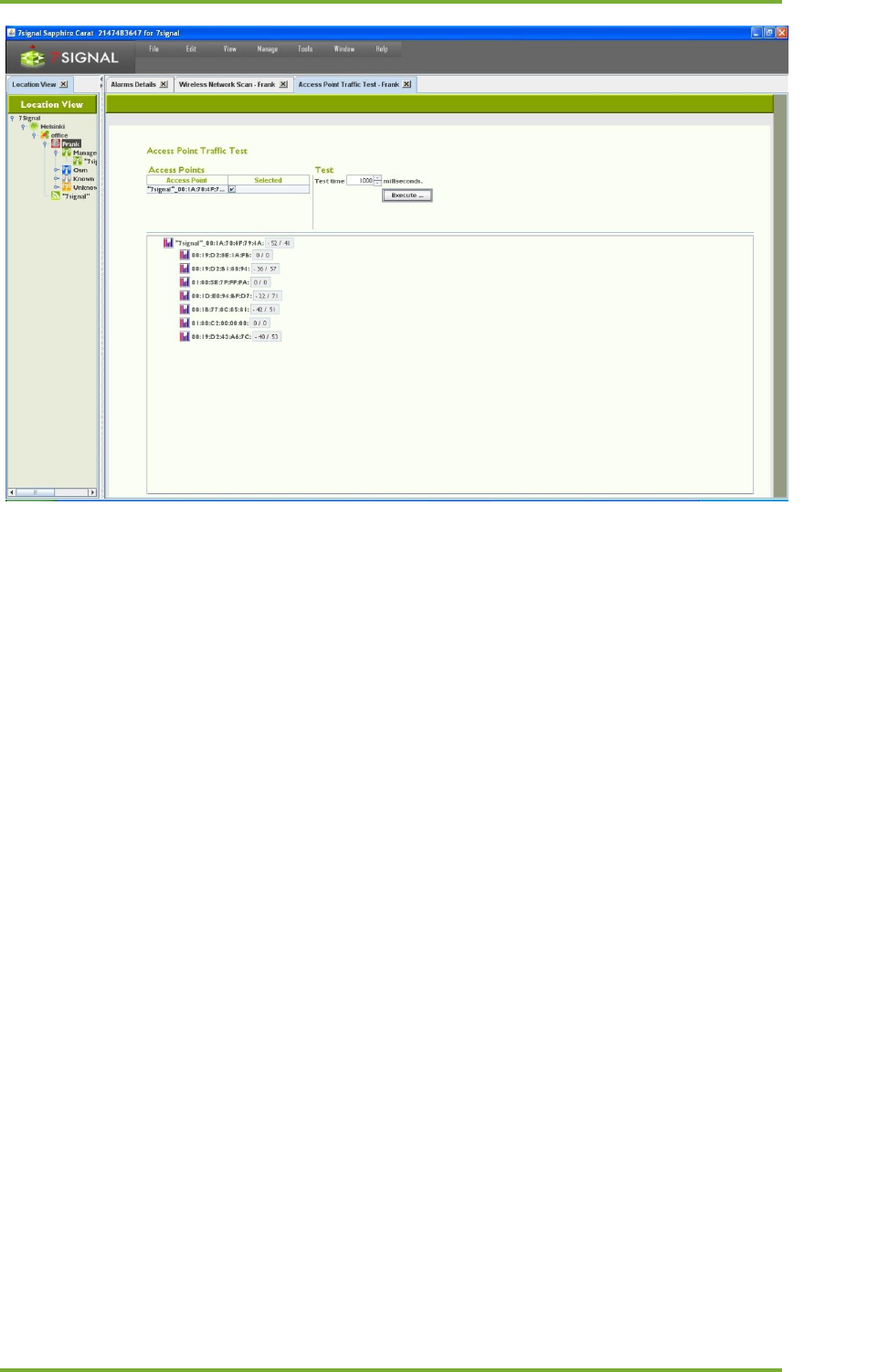
18 Manual tests 67
7signal Ltd, Panuntie 6, FI-00620 HELSINKI, FINLAND, +358 40 777 7611, info@7signal.com, www.7signal.com
7signal Sapphire Carat Carat User Guide Release 3.1
18.13 “MOS test”
This test creates a VoIP call between Sapphire Eye and Sonar. Both uplink and downlink call
quality can be measured.
1. In the Network topology, select the Eye that will run the test
2. Right-click and select ”Manual tests | Http test”
3. Define the test target in the target area:
a. Select the Sonar against which you want to run the test
b. Select an access point from the pull-down menu
c. Select the Eye’s IP address (DHCP or static)
i. If static, enter the (1) local IP address, (2) local netmask, and (3)
gateway
4. Configure the test data (see separate instructions)
5. Select “Execute”
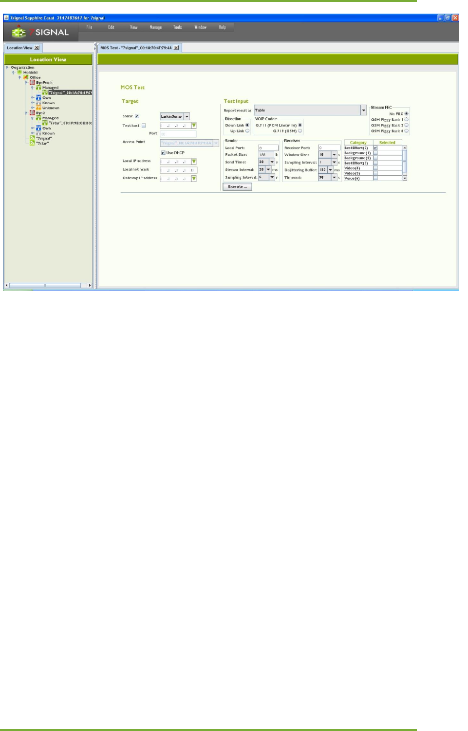
18 Manual tests 68
7signal Ltd, Panuntie 6, FI-00620 HELSINKI, FINLAND, +358 40 777 7611, info@7signal.com, www.7signal.com
7signal Sapphire Carat Carat User Guide Release 3.1
18.13.1 MOS test parameters
1. Select the initial display format for the results (Table/Graph)
2. Select the direction of the test (Downlink/Uplink)
3. Select the codec to be used in the test (VoIP Codec):
a. G.711 PCM Linear 16 = 64 kbit/s
b. G.729 GSM data = 8 kbit/s
4. Select an optional error correction method (Stream FEC)
5. Configure sender information:
a. Enter a port for the MOS test (Local port)
b. Enter the test duration in seconds (Send time)
c. Enter the packet interval in milliseconds (Stream interval)
d. Enter the packet size in bytes (Packet size)
e. Enter the sampling window size in seconds (Sampling interval)
6. Configure the receiver information:
a. Enter a port for the MOS test (Receiver port)
b. Enter the receiving window size in seconds (Window size)
c. Enter the sampling interval in seconds (Sampling Interval)
d. Enter the size of the dejittering buffer (Dejittering Buffer)
e. Enter the connection timeout in milliseconds (Timeout)
7. Enter the traffic class (licensed feature only)
8. Select “Execute”
9. The results are displayed in a new window in the selected format
18.13.2 MOS Test Result
Sample result set:
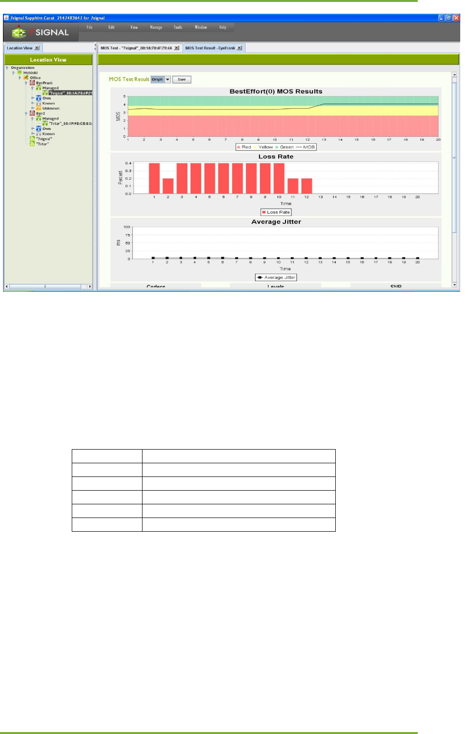
18 Manual tests 69
7signal Ltd, Panuntie 6, FI-00620 HELSINKI, FINLAND, +358 40 777 7611, info@7signal.com, www.7signal.com
7signal Sapphire Carat Carat User Guide Release 3.1
Elements of the results image:
• MOS result: The distribution of MOS values related to test duration. The color coding
indicates quality.
• Loss Rate: Packet loss as a function of test duration.
• Average Jitter: Variation in delay as a function of test duration.
• Codec: The distribution of codecs used during the test. If only one result is visible, the
codec was not changed during the test.
• Levels: Signal and noise levels during the test, averaged over the duration of the test.
• SNR: Signal/noise ratio during the test, averaged over the duration of the test.
Test result
5
Excellent
4
Good
3
Fair
2
Poor
1
Bad
In practice, the supported codec’s can reach MOS scores that are slightly above 4.
18.14 “HTTP URL test”
This test is used for “downloading” actual WWW-pages.
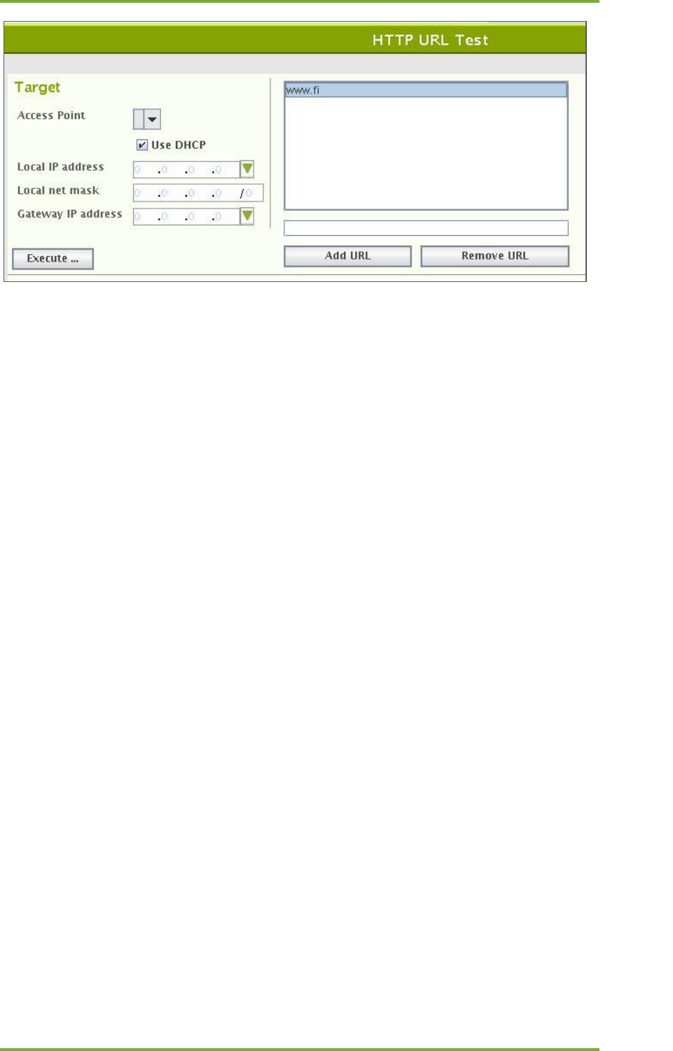
18 Manual tests 70
7signal Ltd, Panuntie 6, FI-00620 HELSINKI, FINLAND, +358 40 777 7611, info@7signal.com, www.7signal.com
7signal Sapphire Carat Carat User Guide Release 3.1
To run the Intranet test:
1. Select an access point from the pull-down menu
2. Select the Eye’s IP address (DHCP or static)
a. If static, enter the (1) local IP address, (2) local netmask, and (3) gateway
3. Choose URL from the box
a. To add a URL
i. Write a well-formed and proper address to the input box
ii. Select “Add URL”
b. To remove a URL
i. Activate the URL to be removed with a right-click
ii. Select “Remove URL”
4. Select Execute.
The result marks whether the download was successful (protocol errors or not), the download
time and the downloaded byte count.
18.15 “Internet AvailabilityTest”
This is an infrastructure test that reflects how well a wlan client (Eye) is able to utilize the
Internet. The test includes the following steps:
- radio link setup
- wlan authentication
- DHCP service
- Gateway pinging
- DNS server checks
- DNS name resolves
If the Eye passes all the phases of the test, it is justified to assume that the internet use is in
general fully functional.
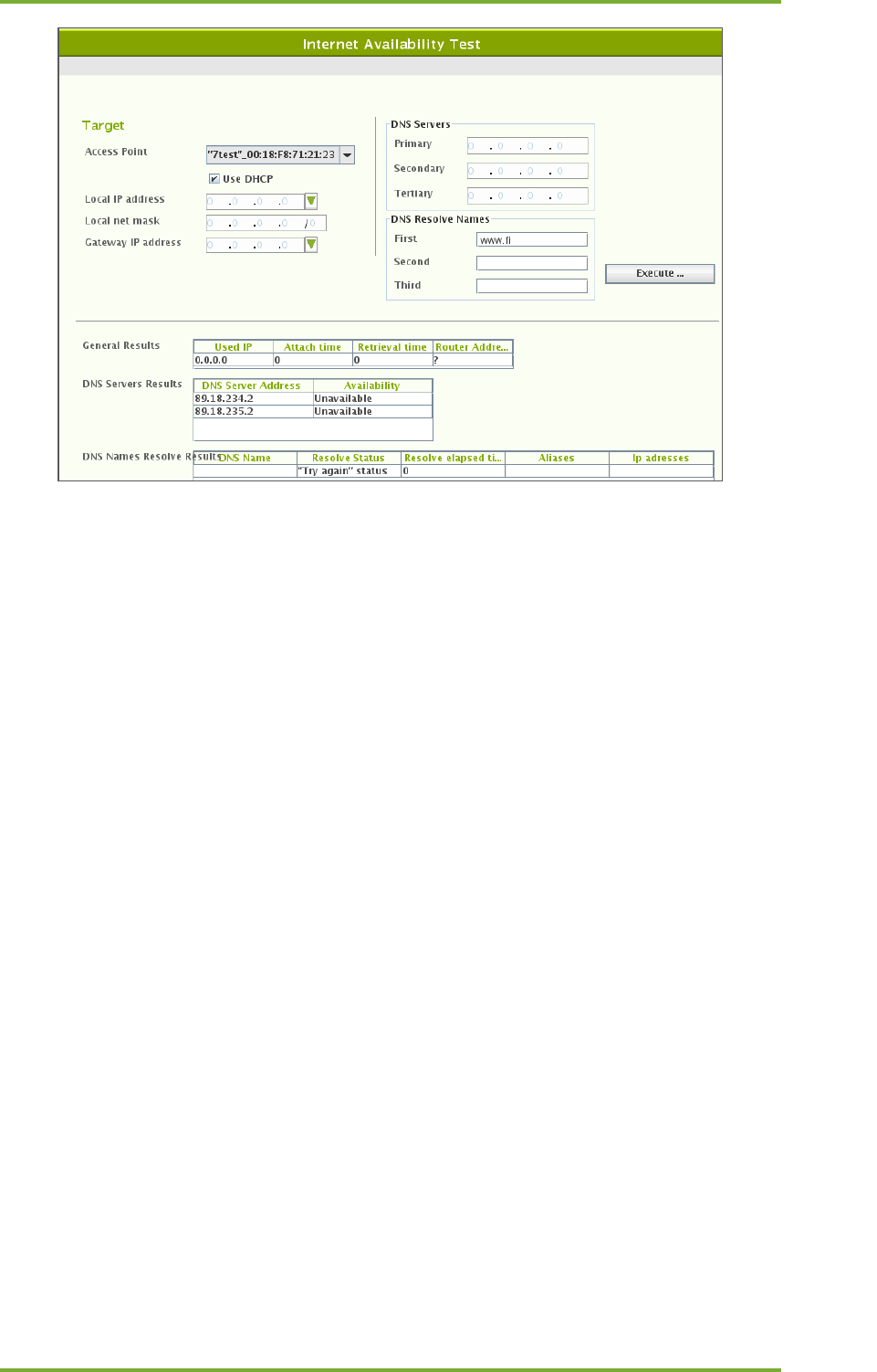
18 Manual tests 71
7signal Ltd, Panuntie 6, FI-00620 HELSINKI, FINLAND, +358 40 777 7611, info@7signal.com, www.7signal.com
7signal Sapphire Carat Carat User Guide Release 3.1
To run the Internet availability test:
1. Select an access point from the pull-down menu
2. Select IP address
a. Use DHCP of the wlan network by checking the box
i. DHCP result shall affect other test parameters as the actual servers
shall be dictated by the result and the reliability is expected.
b. Use of static IP address configuration
i. enter the (1) local IP address, (2) local netmask, and (3) gateway
ii. Enter primary DNS server
iii. Enter secondary DNS server (optional)
iv. Enter tertiary DNS server (optional)
c. Enter 1st network name to be resolved
d. Enter 2nd network name to be resolved (optional)
e. Enter 3rd network name to be resolved (optional)
3. Select “Execute”
The result-set is three-fold:
1. General results: IP address obtained, attach time, dhcp retrieval time and gateway
address.
2. Status of DNS servers
3. Results of the name resolving.
18.16 “SIP Register Test”
It is possible to run SIP REGISTER test in both unauthorized and authorized mode.
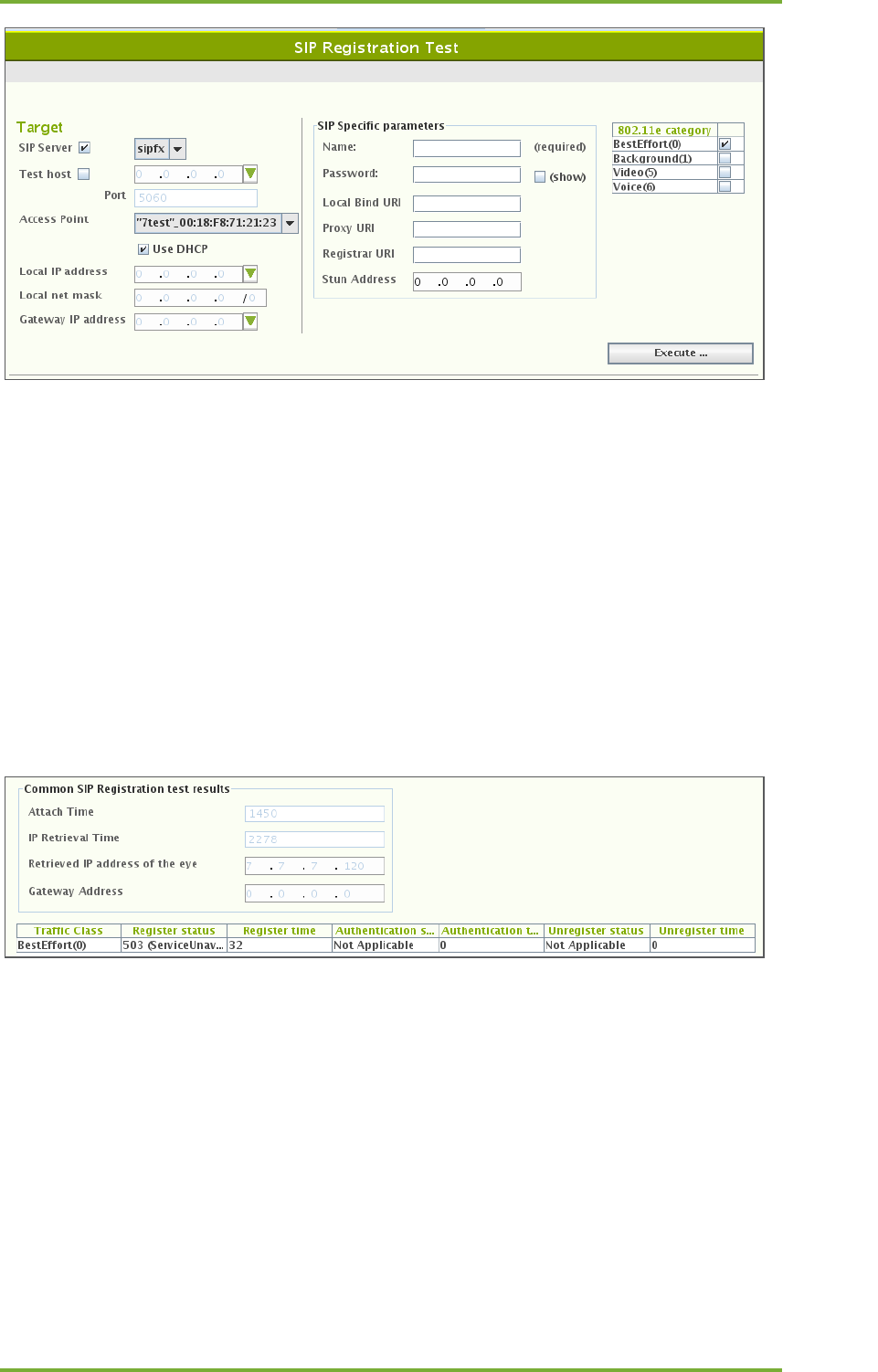
18 Manual tests 72
7signal Ltd, Panuntie 6, FI-00620 HELSINKI, FINLAND, +358 40 777 7611, info@7signal.com, www.7signal.com
7signal Sapphire Carat Carat User Guide Release 3.1
To run the SIP test:
1. Select the SIP server to register to
a. From the pull-down menu
i. SIP end-point has to be defined as a test end-point to be selectable
b. Arbitrary IP address
i. Enter IP address and the port
2. Select an access point
3. Select the Eye’s IP address (DHCP or static)
a. If static, enter the (1) local IP address, (2) local netmask, and (3) gateway
4. Enter the SIP protocol specific parameters
a. Name is mandatory
b. If alone, the test is run as un-authorized
5. Select the wlan traffic category
6. Select “Execute”
The test result is two-fold: test setup information and SIP specific.
Test setup information contais:
- attach time
- dhcp retrieval time
- Eye IP address used in wlan interface
- The gateway
SIP results contain:
- used IEEE802.11e traffic category
- SIP server response for REGISTER: SIP protocol code
- Register time, milliseconds
- Authentication information (optional)
- SIP server response for UNREGISTER: SIP protocol code

18 Manual tests 73
7signal Ltd, Panuntie 6, FI-00620 HELSINKI, FINLAND, +358 40 777 7611, info@7signal.com, www.7signal.com
7signal Sapphire Carat Carat User Guide Release 3.1
- Unregister time, milliseconds
19 Service Level Agreement 74
7signal Ltd, Panuntie 6, FI-00620 HELSINKI, FINLAND, +358 40 777 7611, info@7signal.com, www.7signal.com
7signal Sapphire Carat Carat User Guide Release 3.1
19 SERVICE LEVEL AGREEMENT
Service Level Agreement (SLA) groups a number of KPIs and their expected target values. In a
nutshell, typically a KPI has a scalar value while SLA is combination of numerous KPI values and
statistical rules that result in a higher-level view on the quality of the network.
The ultimate goal is to bind together a contractual agreement and actual measurements, the
expression of the desired or required level of the service and the proven real-life phenomena.
As such, the SLA is a communication medium between the service provider and the customer.
The SLA outcome is percentage value and based on user-defined thresholds it is divided into
values green, yellow and red according the three-basket principle. This means that the end-
user experience on the wlan network might remain adequate but the resulting SLA value is
clearly in the red basket.
Related icons
SLA template SLA KPI definition
SLA group KPI definition
19.1 Defining a Service Level Agreement into the system
A network service provider can make Service Level Agreements (SLA) with their customers,
defining the level of service provided to the customer. 7signal Sapphire enables users to
monitor the fulfillment of the various performance level guarantees defined in the SLA.
The user may freely choose the performance indicators to be monitored in the
service level agreement, in effect forming out of them an SLA group.
19.2 Defining SLA Key Performance Indicators (KPI)
In 7signal Sapphire an SLA group is formed out of a set of Key Performance Indicators
corresponding to the SLA. The SLA group is bound to a topology element in the monitored
network.
An SLA group consists of several KPIs which define the boundary values used in monitoring the
fulfillment of the service level agreement.
In the 7signal Sapphire system the boundary values can be set separately for each KPI
contained in the SLA group. Each KPI defines a certain type of boundary value and percentage
values for how many measurement samples may fall outside the defined boundary values
without causing the service level agreement to be considered unfulfilled. The type of the KPI
determines whether measurement samples with values over or under the boundary value are
desired.
Three color coding is used for service levels in the KPIs: green, yellow and red. The percentage
boundaries are defined for green and yellow levels of service.
To attain the green level of service the percentage of measurement samples that fulfill the
boundary value criteria set in the KPI (that is, are over or under the set boundary value,
depending on the type of KPI) must be at least as high as the percentage boundary value set
for the green level in the KPI. If there are too many measurement samples that do not fulfill
the boundary value criteria, the service level falls to yellow. The yellow level functions likewise:
if it is not attained, the service level falls to red.
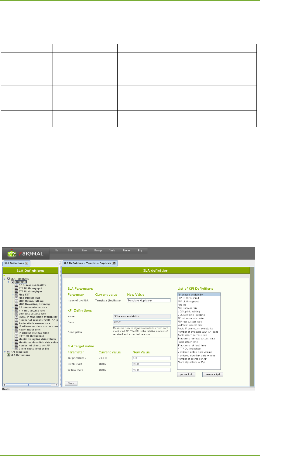
19 Service Level Agreement 75
7signal Ltd, Panuntie 6, FI-00620 HELSINKI, FINLAND, +358 40 777 7611, info@7signal.com, www.7signal.com
7signal Sapphire Carat Carat User Guide Release 3.1
19.3 Example: Upload throughput KPI
The table below explains how an SLA value is calculated based on target KPI, it’s measurement
and statistical analysis.
Boundary value
above 5,5 Mbit/s
The threshold value for KPI.
Green level
99,0%
At least 99,0% of measured samples must attain
an upload throughput of at least 5,5Mbit/s in
order to attain the green level for the KPI in
question.
Yellow level
95,0%
If the percentage of measured samples that
satisfy the boundary value criteria falls between
95,0% and 98,99% the yellow level is attained.
Red level
below 95,0%
If the percentage falls below 95,0% the service
level can be considered unfulfilled.
19.4 Creating an SLA group
An SLA group can be created in one of two ways:
1. By copying an SLA template
2. By creating an empty SLA group and adding to it the desired Key Performance
Indicators
When the desired set of KPIs has been added to the SLA group the KPI boundary values can be
set to match the service levels outlined in the actual Service Level Agreement contract.
19.4.1 Creating an SLA group from a template
Create the SLA group as follows:
1. Click on "Manage | SLA definitions" from the top menu bar
2. Open Templates node.
3. Right-click on the desired SLA template

19 Service Level Agreement 76
7signal Ltd, Panuntie 6, FI-00620 HELSINKI, FINLAND, +358 40 777 7611, info@7signal.com, www.7signal.com
7signal Sapphire Carat Carat User Guide Release 3.1
4. Choose "Duplicate" from the pop-up menu. An SLA group editing dialog opens to the
right (pictured above)
5. Name the SLA group
6. Remove unnecessary KPIs from the "KPI definitions" list by using the "Remove KPI"
button
7. Add wanted KPI’s which are not within the template. See next chapter how to do this.
8. If it's desired to change the boundary values of KPIs, choose the desired KPI from the
"KPI definitions" list. The KPI's name, description and boundary values according to
service level agreement are updated into the editing dialog.
9. Edit the boundary values to your liking.
10. Repeat from step 7. until every boundary value is as desired.
11. Click "Save"
19.4.2 Creating an SLA group from scratch
The dialog pane is identical to the case of duplicated template. Naturally the contents of the
pane are empty, but the look and the process is identical.
Create the SLA group as follows:
1. Click on "Manage | SLA definitions" from the top menu bar
2. Right-click on "SLA groups" from the tree hierarchy
3. Choose "Add SLA group" from pop-up menu. An SLA group editing dialog opens to the
right.
4. Name the SLA group
5. Choose "KPI definitions" from the tree hierarchy. Available KPIs are opened into the tree.
6. Right-click on the desired KPI
7. Choose "Copy" from the pop-up menu
8. Click "Paste KPI" from the SLA group editing dialog
9. Choose the KPI in the SLA group editing dialog ("KPI definitions"). The KPI's name,
description and boundary values according to service level agreement are updated into
the editing dialog.
10. If necessary, edit the boundary values.
11. Repeat from step 6. onwards until all desired KPIs have been added to the SLA group.
12. Click "Save"
19.4.3 Binding an SLA group to a Link
Bind an SLA group to a link as follows:
1. Click on "View | Network topology" from the top menu bar
2. Right-click on the link that you want to bind an SLA group to from the tree hierarchy
3. Choose "Set SLA group" from the pop-up menu
4. Choose the desired SLA group from the menu that opens
or alternatively
1. Click on "View | Network topology" from the top menu bar
2. Right-click on the link that you want to bind an SLA group to from the tree hierarchy
3. Select "Edit" from the pop-up menu. A link editing dialog opens to the right
4. Choose the desired SLA group from the drop-down menu
5. Click "Save"

19 Service Level Agreement 77
7signal Ltd, Panuntie 6, FI-00620 HELSINKI, FINLAND, +358 40 777 7611, info@7signal.com, www.7signal.com
7signal Sapphire Carat Carat User Guide Release 3.1
19.4.4 Binding an SLA group to a link group
Bind an SLA group to a link group as follows:
1. Click on "View | Network topology" from the top menu bar
2. Right-click on the link group that you want to bind an SLA group to from the tree
hierarchy
3. Choose "Set SLA group" from the pop-up menu
4. Choose the desired SLA group from the menu that opens
or alternatively
1. Click on "View | Network topology" from the top menu bar
2. Right-click on the link group that you want to bind an SLA group to from the tree
hierarchy
3. Select "Edit" from the pop-up menu. A link group editing dialog opens to the right
4. Choose the desired SLA group from the drop-down menu
5. Click "Save"
19.4.5 Binding an SLA Group to other Entities
SLA Group can be bound to any entity within the Topology Tree. This can be done as follows
1. Right click the topology element and select “Bind SLA”
2. Select the SLA from the given list.
19.4.6 SLA propagation hierarchy
There is a propagation hierarchy how SLA Groups are propagated from different levels within
the topology hierarchy. This means that for example if SLA Group is only bound to Top level
organization, it is propagated to each element under the organization. Following is a order of
propagation from left to right for the rightmost element. Element right always overrides
propagation from the left.
Organization > Location > Service Area > Access Point > Link Group > Link
Organization > Location > Link Group
Organization > Location > Service Area > Eye
Organization > Wireless Network
Organization > Location > Service Area > Access Point
Organization > Location > Service Area
Organization > Location
Organization
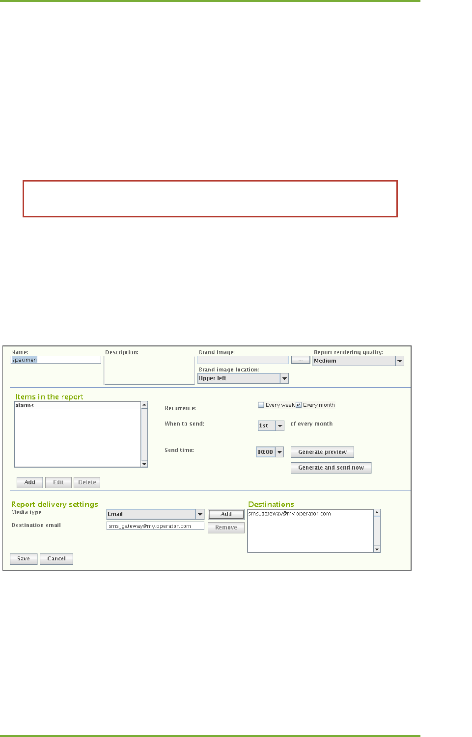
20 Continuos And Automated Reporting 78
7signal Ltd, Panuntie 6, FI-00620 HELSINKI, FINLAND, +358 40 777 7611, info@7signal.com, www.7signal.com
7signal Sapphire Carat Carat User Guide Release 3.1
20 CONTINUOS AND AUTOMATED REPORTING
Loupe is an interactive tool for studying network phenomena of interest and for in-depth
investigation of problems. Reports in standard, easy-to-interpret formats are available to
support routine monitoring.
By using the report view in Carat, the user can configure reports from elements that are
familiar from Loupe. In addition to the user-selected indicators, a report configured here
contains the time of compilation and delivery and a list of the delivery addresses. At the
specified time, Carat generates the report and delivers it to the recipients, specified as either
e-mail addresses or directories in the Carat server file system. A report can include KPIs,
service level views, and alarms, referred to below as report items.
Note: Configuring the mail server settings found under “Edit | SMTP server”
enables the use of email in reporting.
20.1 Subscription for a new report
1. Select “Manage | Automated report configuration”
2. Select “New” to create a new subscription and open a report template
a. Use “Edit” for editing a subscription
b. The “Delete” option allows you to delete a subscription
c. When you select a report name, the description of this existing report is displayed
In the “Report Properties Configuration” area:
3. Enter a name for the subscription
4. Enter a description for the subscription (optional)
5. Select an report image (optional)
6. Choose the location for the image on the page
The image will be repeated on each page of the report. It might represent, for example, a
company or a target network.
7. Select the resolution (quality) to be used for the report graphics, mainly relevant to
charting.
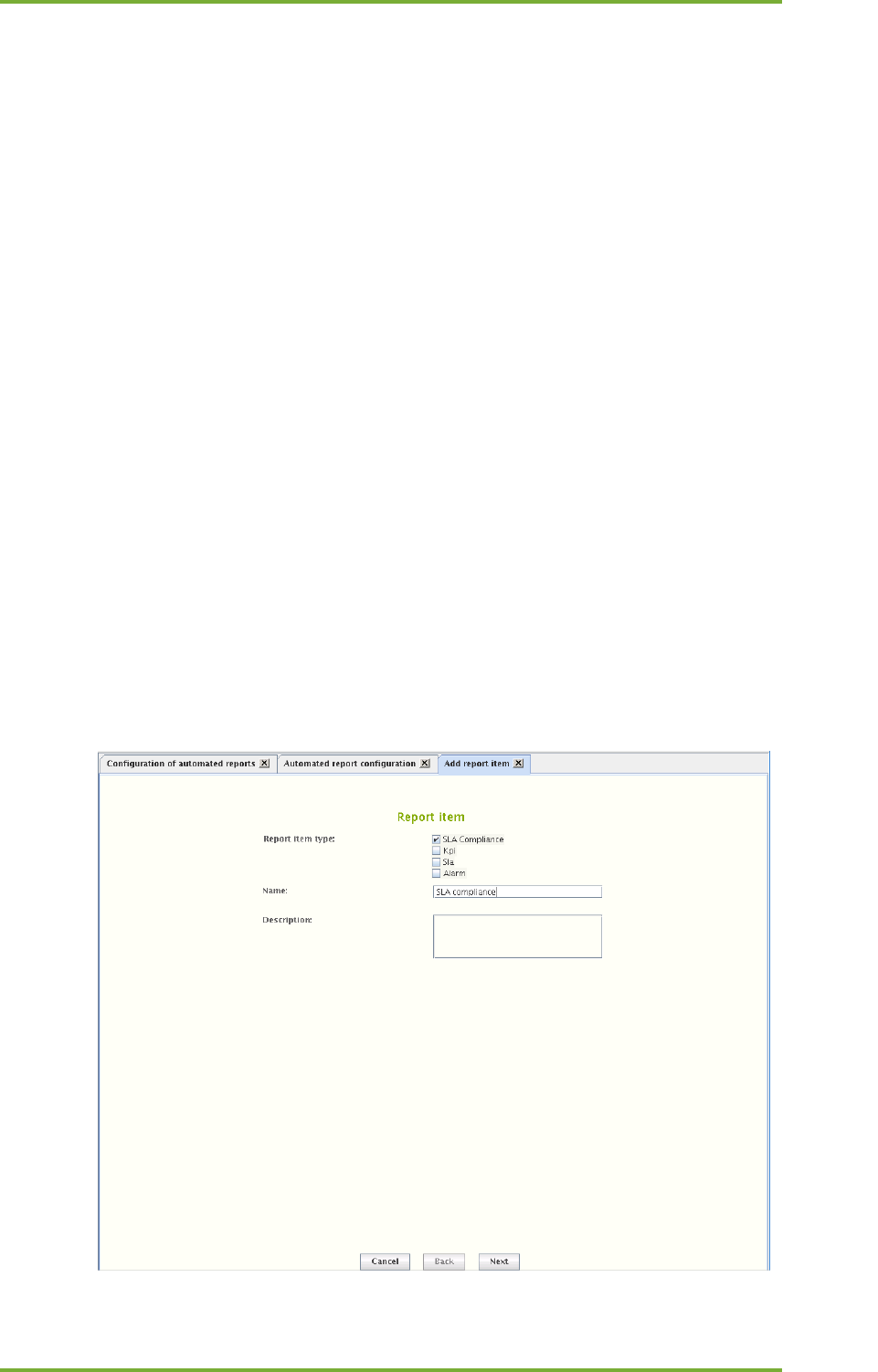
20 Continuos And Automated Reporting 79
7signal Ltd, Panuntie 6, FI-00620 HELSINKI, FINLAND, +358 40 777 7611, info@7signal.com, www.7signal.com
7signal Sapphire Carat Carat User Guide Release 3.1
In the “Report items” area:
8. Configure the items to be included in the report by selecting “Add”
a. this starts content-dependent workflows, instructions below
9. Specify the send time
a. recurrence is weekly or monthly
i. Field “When to send” is dynamic and let’s one choose either numerous
week days or a day in month
b. send time has 30 minutes resolution in a drop-down menu
10. “Generate preview” creates a report and opens it is a viewer tool
11. “Generate and send now” are available for subscriptions that have been saved.
In the “Report destination settings” area:
12. Choose the delivery format (Media type) of the PDF report
a. Email
b. save to File system
i. an absolute path gives the location in the Carat server file system
ii. relative paths are relative to the Carat startup directory (default:
/opt/7signal/Carat/7signal)
13. Add one or more formats in the “Destinations” field by clicking “New”
14. Save the subscription by clicking “Save”
20.2 Adding Report Items
There are four report item types. A report item is an individual piece of information – SLA
compliance, a KPI chart, SLA table or a set of alarms – that is part of the report. A report is a
series of report items.
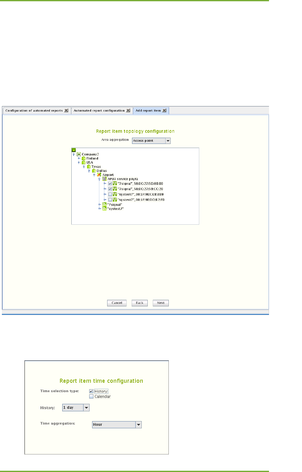
20 Continuos And Automated Reporting 80
7signal Ltd, Panuntie 6, FI-00620 HELSINKI, FINLAND, +358 40 777 7611, info@7signal.com, www.7signal.com
7signal Sapphire Carat Carat User Guide Release 3.1
To add a report item:
1. Choose the content type
2. Give a name to the report item
a. a descriptive name is good especially if the item content groups together
numerous pieces of information
3. Optionally write a description of the report item
4. Select “Next”
20.2.1 Adding SLA compliance report item
1. Select the method of aggregation in Area aggreation
2. From the hierarchical tree presented, select the corresponding elements depending on
the selected area aggregation.
3. Click “Next” to continue to “Report item time configuration”
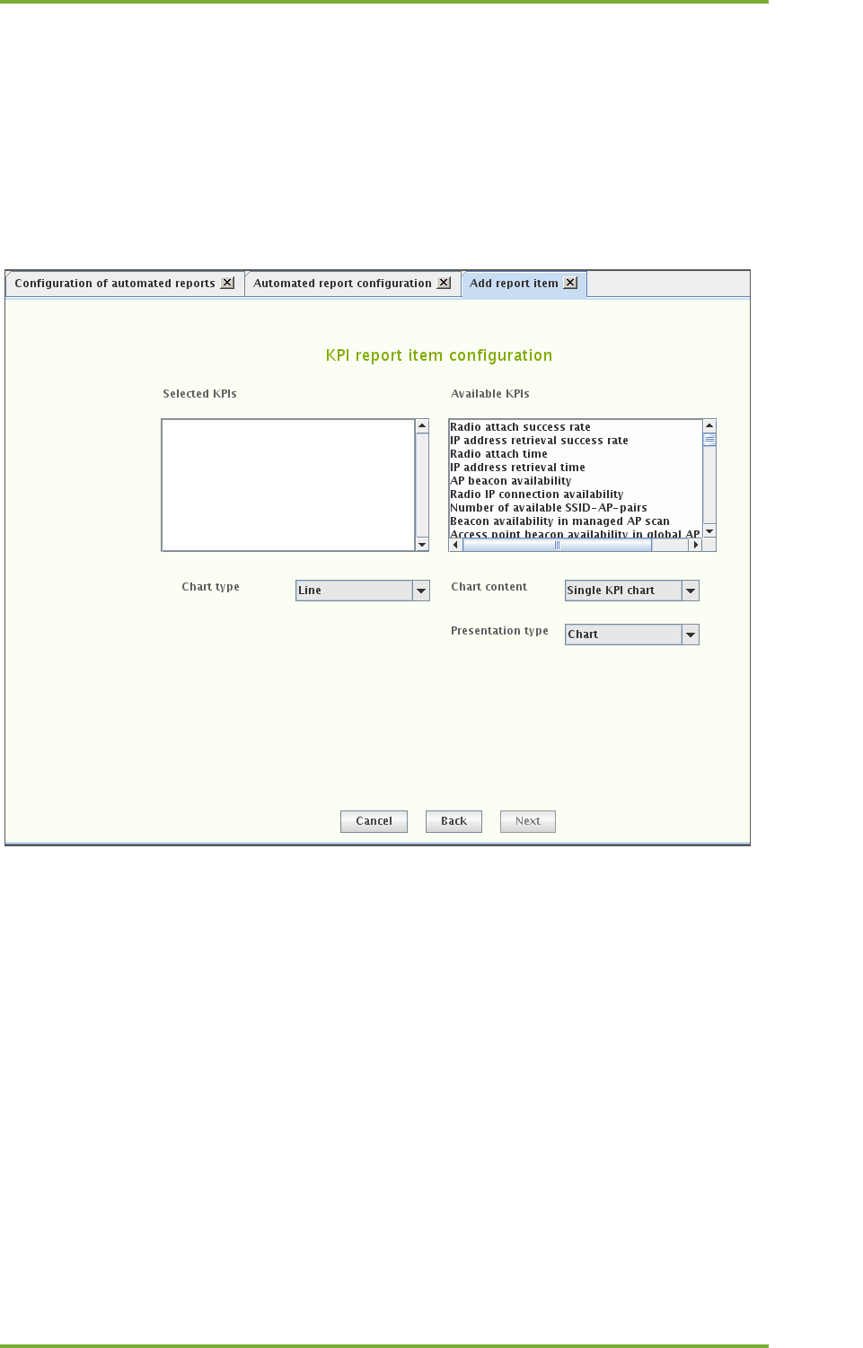
20 Continuos And Automated Reporting 81
7signal Ltd, Panuntie 6, FI-00620 HELSINKI, FINLAND, +358 40 777 7611, info@7signal.com, www.7signal.com
7signal Sapphire Carat Carat User Guide Release 3.1
4. Select the time interval for the report
a. History uses pre-defined intervals from the generation time backwards
b. Calendar (in the picture above) allows free interval definition
5. Time aggregation defines the averaging period for the report item
6. Click “Finish” to return to first subscription page
20.2.2 Adding KPI report item
7. Select the desired KPI by left-clicking it in the right-hand pane
8. Right-click and select “Add KPI” in the submenu
9. Repeat steps 2–3 until all desired KPIs are in the left pane
10. Select the Chart type
11. Select the method for displaying the measurement series in Chart content
12. Select the display method
a. Data Table, Aggregation Chart
13. Click “Next” to continue to “Report item topology configuration”
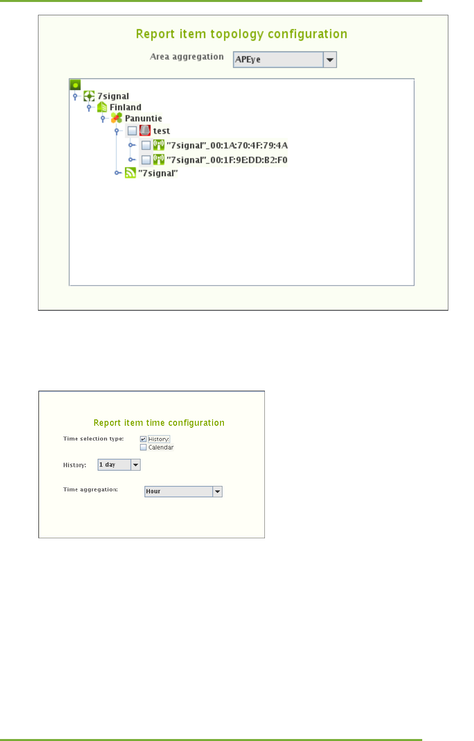
20 Continuos And Automated Reporting 82
7signal Ltd, Panuntie 6, FI-00620 HELSINKI, FINLAND, +358 40 777 7611, info@7signal.com, www.7signal.com
7signal Sapphire Carat Carat User Guide Release 3.1
14. Select the method of aggregation in Area aggreation
15. From the hierarchical tree presented, select the corresponding elements depending on
the selected area aggregation.
16. Click “Next” to continue to “Report item time configuration”
17. Select the time interval for the report
a. History uses pre-defined intervals from the generation time backwards
b. Calendar (in the picture above) allows free interval definition
18. Time aggregation defines the averaging period for the report item
19. Click “Finish” to return to first subscription page
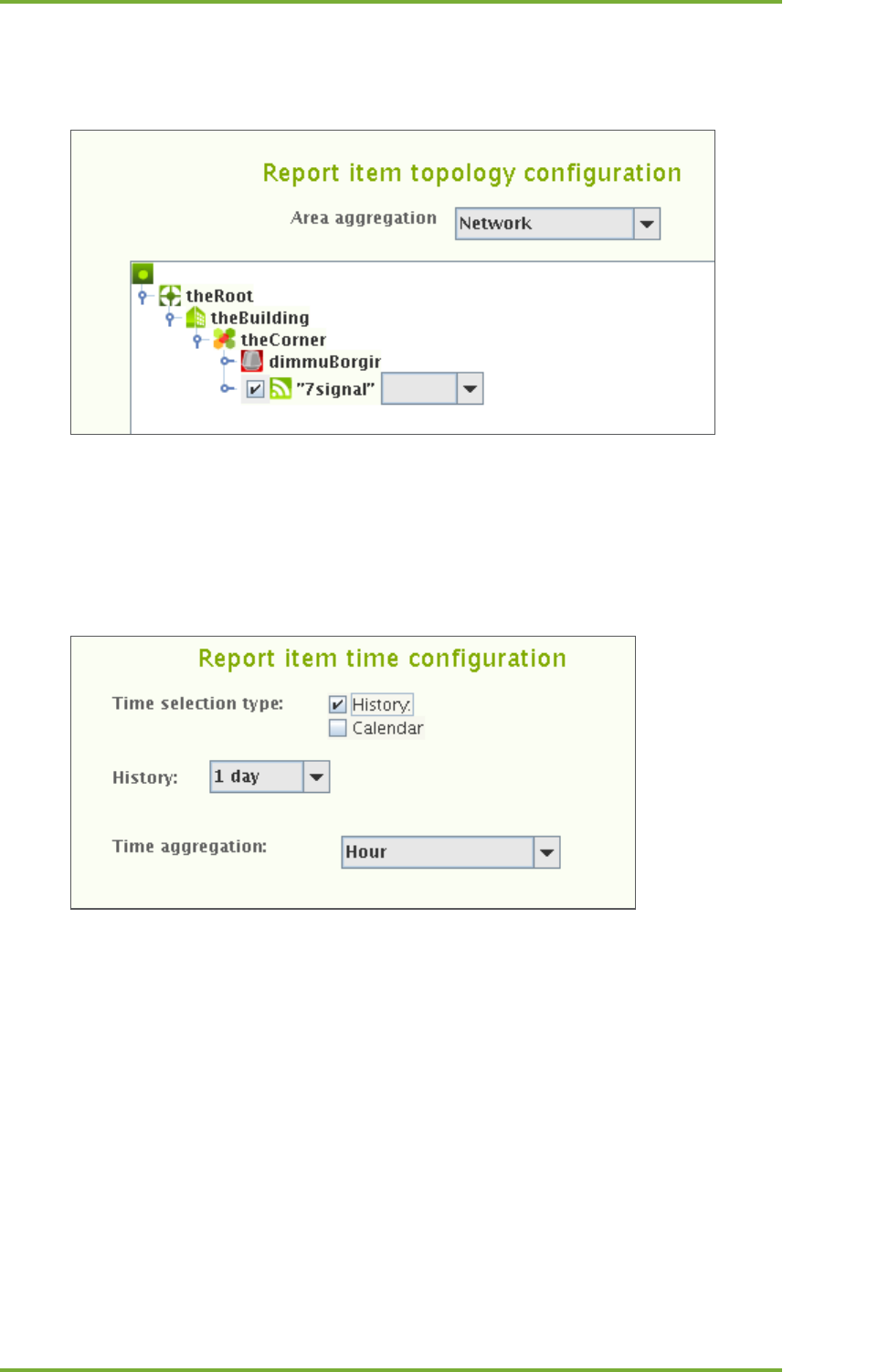
20 Continuos And Automated Reporting 83
7signal Ltd, Panuntie 6, FI-00620 HELSINKI, FINLAND, +358 40 777 7611, info@7signal.com, www.7signal.com
7signal Sapphire Carat Carat User Guide Release 3.1
20.2.3 Adding SLA report item
.
1. Choose the appropriate aggregation in the drop-down box.
2. Select the elements in the topology tree
3. Select the SLA group to be applied. Available SLA groups are in a drop-down menu on
the right of the topology element name.
4. Repeat steps 2-3 until all desired elements are bound to SLA groups.
5. Click “Next” to continue to “Report item time configuration”
6. Select the time interval for the report
a. History (in the picture above)uses pre-defined intervals from the generation
time backwards
b. Calendar allows free interval definition
7. Time aggregation defines the averaging period for the report item
8. Click “Finish” to return to first subscription page
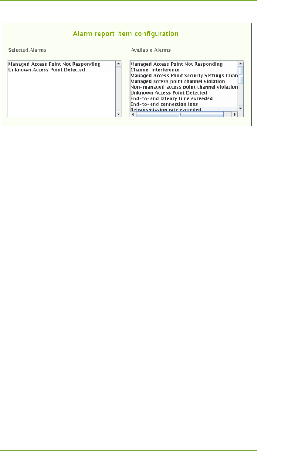
20 Continuos And Automated Reporting 84
7signal Ltd, Panuntie 6, FI-00620 HELSINKI, FINLAND, +358 40 777 7611, info@7signal.com, www.7signal.com
7signal Sapphire Carat Carat User Guide Release 3.1
20.2.4 Adding alarm report item
1. Select the desired alarm by left-clicking it in the right-hand pane
2. Right-click the alarm and select “Add alarm” in the submenu
a. One may remind oneself about the alarm by selecting “Description”
3. Repeat steps 2–3 until all of the desired alarms are in the left pane
4. Select “Next” to continue to “Report item topology configuration”
5. Select the method of aggregation in Area aggregation
6. From the hierarchical tree presented, select the access points or networks to be
included in the report by ticking the check-boxes
7. Select “Next” to continue to “Report item time configuration”
8. Select the time interval for the report
a. History uses pre-defined intervals from the generation time backwards
b. Calendar allows free interval definition
9. Time aggregation defines the averaging period for the report item
10. Click finish to return
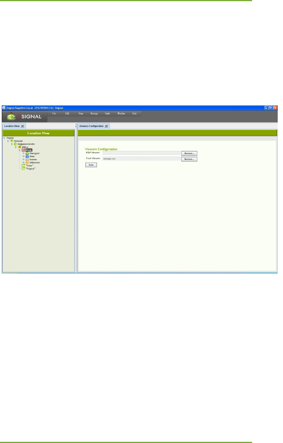
21 Viewer Software 85
7signal Ltd, Panuntie 6, FI-00620 HELSINKI, FINLAND, +358 40 777 7611, info@7signal.com, www.7signal.com
7signal Sapphire Carat Carat User Guide Release 3.1
21 VIEWER SOFTWARE
Test result information and other results can be transferred outside Carat in spreadsheet
format and as raw or delimited text and pdfs. You can select the applications you want to use
to process these files in Carat.
1. From the top menu bar, select “Edit | Configure viewers”
2. The installed applications are displayed on the right
3. To change the applications, click “Browse”
4. Locate the application in the Carat server file system and select “Open”
5. Click “Save”
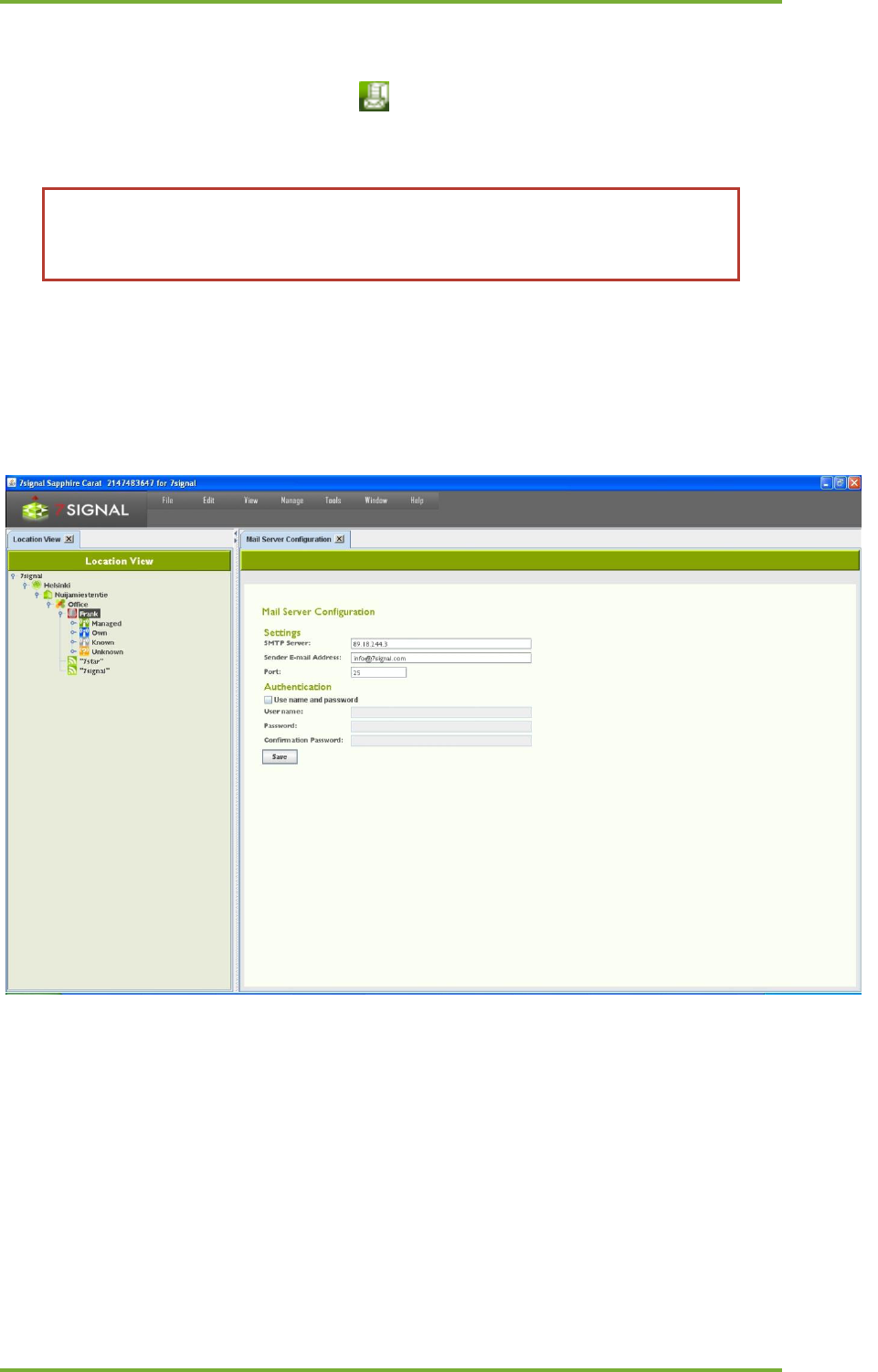
22 Email Servers 86
7signal Ltd, Panuntie 6, FI-00620 HELSINKI, FINLAND, +358 40 777 7611, info@7signal.com, www.7signal.com
7signal Sapphire Carat Carat User Guide Release 3.1
22 EMAIL SERVERS
When one configures an email server (icon ), one can send reports and alarms to email
addresses. This setting is only for the SMTP server, the email account information is given in
each of the features using the SMTP server.
There should be only one SMTP per organization. Solution Administrator has
visibility to all SMTP servers but local Administrators and Configurators may add
only one SMTP server.
1. From the top menu bar, select “Edit | Mail server configuration”
2. Enter the SMTP server’s address
3. Enter the recipient’s e-mail address
4. Enter the SMTP port to use
5. Enter a username and password, if required by the SMTP server
6. Click “Save”

23 Database Backup 87
7signal Ltd, Panuntie 6, FI-00620 HELSINKI, FINLAND, +358 40 777 7611, info@7signal.com, www.7signal.com
7signal Sapphire Carat Carat User Guide Release 3.1
23 DATABASE BACKUP
It is possible to backup databases in 7signal Sapphire. Given a proper backup, the system state
may be recovered completely in case of system crash. There are two remarkably different
alternatives and an option not to backup the database. The default in 7signal Sapphire is no
backup. While this option is known to be non-optimal for any production environment, it is
chosen as default to force every organization to define their own backup policy.
23.1 Backup options
The backup process will use /tmp directory by default and take a lot of disk space.
The directory can be changed with 7db-utility.
Example:
# 7db backup workdir set /largefilesys
23.1.1 Automated backup with server downtime
Backup with downtime is a circadian backup based on Unix cron that pauses the
measurements by stopping the Carat server and closing the underlying database connections.
In quiescent mode a full backup of the database is made and stored to the desired location in
the Carat server file system. The user is responsible for managing the backup files, moving and
purging and so on. This type of logging is later referred as offline backup.
Example:
# 7db backup set daily 03:00 /mnt/backups
23.1.2 Automated backup without server downtime
Online backup is a circadian backup based on Unix cron that keeps 7signal Sapphire in
production while creating the backups.
Database logging method should be archival logging.
Example:
# 7db backup set daily 03:00 /mnt/backups
23.1.3 Manual backup
Circular logging
Sapphire processes will be stopped during backup process and automatically restarted after
backup has been created.

23 Database Backup 88
7signal Ltd, Panuntie 6, FI-00620 HELSINKI, FINLAND, +358 40 777 7611, info@7signal.com, www.7signal.com
7signal Sapphire Carat Carat User Guide Release 3.1
Example:
# 7db backup now /mnt/backups offline
Archival logging
Sapphire processes will not be stopped during backup process.
Example:
# 7db backup now /mnt/backups online
23.2 Database logging
In short, the logs of a database system are the most precious. It is justified to say that the logs
are the database as they are written first and the tables are updated after that.
IBM DB2 provides alternative logging methods that affect the backup options. So called
'circular logging' method keeps the size of the logs very predictable. The other option used in
7signal Sapphire is so called 'infinite archive logging'. This is very flexible a logging method
provided that there is a special file system available. Practically the file system must not fill up
ever.
The default logging method in 7signal Sapphire is 'circular logging'.
23.2.1 Purging database logs
Circular logging
There is no need for purging in case of circular logging. The default logging method in 7signal
Sapphire is 'circular logging'.
Infinite archice logging
There is one secure way of purging the log files in the infinite archive directory. Offline backup
has to be done and this comes with price of the 7signal Sapphire halt. Offline backup provides
one single and unique point-in-time to be restored later. Once the offline backup exists, the
log files in the infinite archive directory become obsolete and may be removed.
The other option comes with no warranty whatsoever. The option is to keep 7signal Sapphire
running and to delete log files in the infinite archive directory. To understand what files are
likely to be unused, the active log files has to be followed to see the time to fill up a single log
file and then deduce what infinite archive files might be available for deleting . If one chooses
this option, setting the safety margins reasonably high is advisable.
In case there is both a system crash and a log file has been deleted too early, the
recovery shall never be able to finish. In this case, the only consistent system
stage is available at offline backup time.

23 Database Backup 89
7signal Ltd, Panuntie 6, FI-00620 HELSINKI, FINLAND, +358 40 777 7611, info@7signal.com, www.7signal.com
7signal Sapphire Carat Carat User Guide Release 3.1
The automated reporting lessens the impact of possible data loss if used in detail
and frequently. However, possibility to measurement drill-in analysis is lost as
well as any change in the network topology and other management information.
The infinite archival logging is provided in order to support online backups (see below) but it
should also be seen as a method to make system run longer automatically without user
interruption. However, the system has to be maintained and administered. It is outside of the
scope of this document to fit 7signal Sapphire to IT processes of all organizations but offline
backups with planned system halts are highly recommended.
23.3 Backup method options
23.3.1 Default state (not recommemded)
Essentially the 7signal Sapphire system default state is not a backup system at all but it is
based on the underlying database management system's robustness, fault tolerance and basic
level recovery options. In case of a permanent disk failure the data is lost. By installing the
databases on RAID disks lessens the risk further.
On default state the 7signal Sapphire relies on the database management system (IBM DB2)
logging. The assumptions are that the management information (Eye, access point and target
network) changes are not continuous but rather sporadic. The measurements are continuous
but losing few of the most recent samples is a risk that can be tolerated. Typical starting point
for analysis is one week of measurements and in case of sudden system down one would lose
the data until the system is fixed. And in case of system down it is expected that all the efforts
shall be there to bring 7signal Sapphire and other systems online again. There shall be no
special snapshots where to start operations again. It is possible to resume a state before the
interrupt, possibly the system is operational with no special effort at all.
Offline backups are possible but require user actions both to shutdown 7signal Sapphire and
do the actual backup.
Handicaps of the default method:
- no precise and secure backup (system state) to return to by default
- backup process is completely manual
- backup process requires downtime
Method strengths:
- least planning
- least resource consuming
23.3.2 First degree of backup: offline backup
Most importantly this method gives fully recoverable snapshots at the desired intervals. The
disk space requirement is an issue but not extremely serious as the frequency is totally user-
managed and the file size growth is easy to check (with the tools provided by the operating
system, not by 7signal). The downside is the downtime as the 7signal Sapphire must be halted
for the time of the backup, hence it is called offline backup. Typically this would be rather
minutes than tens of minutes. Naturally all the measurements are stopped for that time.
23 Database Backup 90
7signal Ltd, Panuntie 6, FI-00620 HELSINKI, FINLAND, +358 40 777 7611, info@7signal.com, www.7signal.com
7signal Sapphire Carat Carat User Guide Release 3.1
Offline backup 1st degree is available in every install and run scenario of 7signal Sapphire. One
can start offline backup with a tool or have it run by the system in a circadian manner.
Method handicaps:
- backup process requires downtime
Method strengths:
- simple to recover
- recovered system state is thoroughly consistent
TIP: offline backup is suitable for environments that require automated backup
but do not have special backup policy hardware nor other extensive resources.
23.3.3 2nd degree of backup: online backup
The requirement for the online backup is that infinite archive logging is enabled.
When online backup is operational, the most significant benefit is the ability to run circadian
backups online i.e. 7signal Sapphire remains operational and continues testing while creating
the backup. As opposed to offline backup, the system is online all the time producing
measurements.
The first and the most important assumption is that there is a storage device available that in
practice is a so-called endless device. 7signal cannot and shall not guarantee any checks on the
device but it is assumed to be available all the time and have the capacity for massive data
transfers. The user is responsible for the storage capacity.
NOTE: backups are not done incrementally in any case. This means that over time
the needed to dump the database increases but more importantly the disk space
requirement increases continuously.
NOTE: use of backup systems require planning and administration i.e continuous
effort from the administrator. This area is outside of 7signal scope, 7signal
encourages clear planning on the issue.
During installation there shall be various destination folders inquired by the install script. The
folders are for logs, for bakcup files etc. As complex as online backup may sound, the setting of
the online backup is easy. To maintain and keep it available and functional requires IT support
that is beyond the scope of 7signal guidance.
Behind the scenes the technology relies completely on IBM DB2 backup system and 7signal
provides interface that covers and automates IBM interface to support 7signal databases.
TIP: there are environments that require separate hardware for backups. If
possible, 7signal Sapphire should be integrated (on file system level) to these.
23 Database Backup 91
7signal Ltd, Panuntie 6, FI-00620 HELSINKI, FINLAND, +358 40 777 7611, info@7signal.com, www.7signal.com
7signal Sapphire Carat Carat User Guide Release 3.1
TIP: with frequent and detailed automated reports the loss of measurement data
becomes less drastic as the needed information may be found in the reports.
23.3.4 Changing log settings
Install time gives the option to set all the backup related settings including log setup.
To change the settings while the system is installed and in production later, please use the tool
7db and the logsetup sub-command. Complete guide to 7db tool is in the appendix of
Deployment Guide.
23.3.5 Managing backup levels
By default the system is in default state, no automated backups at all. Any change to that state
would require more resources and administration that should be planned separately.
In case one has changed the default settings – either by giving such install parameters or
issuing the needed commands after the installation - the following operations return the initial
state:
1) stop circadian backups
2) set logging to circular mode
This implies that the default state means circular logging without circadian backups.
23.3.6 File system settings for the database
There are three elements that require – optimally separate – disk space:
1. databases
a. measurement database
b. management database
c. security database
2. database logs
3. database backups
Naturally the backups must be stored separately from the logs and the databases, otherwise
the value of the backups reduces significantly. The databases and the related logs are expected
to be accessible easily from the hosting server but it is encouraged to use separate physical file
systems for these two.
NOTE: log files and databases residing in the same physical disk mean duplicate
disk operation efforts on the same device. It is good design to separate logs and
actual databases to different physical storage devices.
23.3.7 Changing backup settings
Install time gives the option to set all the backup related settings.
To change the settings while the system is installed and in production later, please use the tool
7db and the backup sub-command. Complete guide to 7db tool is in the appendix of
Deployment Guide.
23 Database Backup 92
7signal Ltd, Panuntie 6, FI-00620 HELSINKI, FINLAND, +358 40 777 7611, info@7signal.com, www.7signal.com
7signal Sapphire Carat Carat User Guide Release 3.1
Below there are example commands to give the reader an overview:
# 7db backup remove
# 7db backup set weekly Wed 00:30 /mnt/backups /mnt/backups
# 7db backup set daily 03:00 /mnt/backups
# 7db backup set directory /mnt/newbackups
# 7db backup set weekly Sun 01:30
# 7db backup set type online
# 7db backup now /mnt/backups online
23.4 Restoring backups
Backups are located in the user-defined directory. Backup files contain timestamp in the name,
also the operating system timestamp exists.
NOTE: the user must be aware which backup file should be used. Therefore it is
essential to understand the backup system and the related files.
Based on this information one must choose which backup to restore.
Restore command is
# 7db backup restore <absolute-file-path>
NOTE: while issuing restore command when using online backup, it might be
necessary for the system to retrieve files from the infinite archive directory when
the restore command is issued. The access time is affected by the physical device.
If the system cannot access the files, restore shall not happen. The most recent
offline backup is the alternative point of recovery.

24 Nagios Support 93
7signal Ltd, Panuntie 6, FI-00620 HELSINKI, FINLAND, +358 40 777 7611, info@7signal.com, www.7signal.com
7signal Sapphire Carat Carat User Guide Release 3.1
24 NAGIOS SUPPORT
7signal Sapphire supports Nagios, a commonplace open license tool for IT infrastructure
monitoring.
In this case Sapphire is the object of monitoring, not the monitor itself. Therefore we assume
the general concepts and usage of Nagios to be well-known to the user. If this is not the case,
one may start exploring the topic from the Nagios web pages (http://www.nagios.org). Also, a
recent Nagios release package is included in the delivery media of the 7signal Solution in Sonar
disk and the folder named "Non-7signal Software"
24.1 Adding Sapphire Host Information To Nagios Server
The prerequisite is that Nagios is installed and running on the host machine. In order to
monitor a remote Carat server do the following steps (as a root user):
1. Modify commands.cfg file (default location: /etc/nagios/object/commands.cfg)
Add:
define command {
command_name check_nrpe
command_line $USER1$/check_nrpe -H $HOSTADDRESS$ -c $ARG1$
}
2. Create configuration file for remote machine running the Carat server to Nagios
objects directory (default location: /etc/nagios/objects)
File extension is cfg, otherwise the naming is free. You may use or modify the
following:
carat-host-xyz.cfg
7signal_wqa_carat_1.cfg etc.
Content of the file:
define host {
use linux-server
host_name <host-name-of-the-monitored-server>
alias <alias-of-the-monitored-server>
address <IP address of the monitored server>
}
define service {
use local-service
host_name <host-name-of-the-monitored-server>
service_description 7signal Sapphire Carat
check_command check_nrpe!check_carat_server
}
3. Add host configuration file (the previous step) to nagios.cfg file (default location:
/etc/nagios/nagios.cfg):
cfg_file=/etc/nagios/objects/carat-host-xyz.cfg
4. Restart Nagios server
service nagios restart

24 Nagios Support 94
7signal Ltd, Panuntie 6, FI-00620 HELSINKI, FINLAND, +358 40 777 7611, info@7signal.com, www.7signal.com
7signal Sapphire Carat Carat User Guide Release 3.1
24.2 Adding Nagios Plug-ins To Sapphire Software
The prerequisite is that client-side tools of Nagios have been installed on the host running
7signal Sapphire software. The protocol being used is NRPE. There is no SSH support
concurrently.
24.2.1 Install NRPE daemon
Use online install with yum:
# yum install nrpe
24.2.2 Install toolset ‘Nagios plugins’
Use online install with yum:
# yum install nagios-plugins-nrpe
NOTE: the following installers shall open port tcp/5666 for Nagios traffic in the
firewall settings.Install Sapphire plugin
There folders named Nagios_support on both Carat and Sonar delivery disks. They contain the
following files
7signal-Nagios-plugin-<version-info>-for-Carat-installer.bin
7signal-Nagios-plugin-<version-info>-for-Loupe-installer.bin
7signal-Nagios-plugin-<version-info>-for-Sonar-installer.bin
The files are executable and totally self-contained. By running each of the file makes the
respective Sapphire Nagios plugin available. The process includes configuration file creation,
updates and firewall settings.
Silent install mode (option -s) uses 7signal defaults for all parameters. If this option is not used,
all parameters are inquired interactively with the default setting visible.
By default, the plugin installations end up in /opt/7signal/nagios folder. However, the
installation makes the plugins available and after this the process and operations are
completely transparent to the Carat user.
24.3 Verifying Nagios Installation
Complete and operational install is achieved if Nagios GUI shows
check_carat_server
check_sonar_server
check_loupe_server
as options for monitoring for the hosts running 7signal Sapphire software.
24.4 Removing Nagios plugins
The installation directory contains uninstall_nagios.sh that removes Sapphire related
plugin files. The NRPE daemon stays untouched and its configuration is cleaned only for
Sapphire plugins thus NRPE and other Nagios operations remain untouched.