8E6 Technologies 8E6Enterprise Reporter3 0 Owners Manual ER3.0 V3.06_01
3 to the manual bff7fab8-8cd8-4a87-9620-9d9fd5e17330
2015-02-05
: 8E6-Technologies 8E6-Technologies-8E6Enterprise-Reporter3-0-Owners-Manual-135831 8e6-technologies-8e6enterprise-reporter3-0-owners-manual-135831 8e6-technologies pdf
Open the PDF directly: View PDF ![]() .
.
Page Count: 215 [warning: Documents this large are best viewed by clicking the View PDF Link!]
- Contents
- Enterprise Reporter 3.0 Overview
- Administrator Section
- Introduction
- Chapter 1: Accessing the Server
- Chapter 2: Configuring the ER 3.0 Server
- Administrator GUI
- Network Menu
- Server Menu
- Database Menu
- Page View Elapsed Time screen
- Tools screen
- Expiration screen
- Administrator GUI
- Client User Section
- Introduction
- Chapter 1: Workstation Configuration
- Chapter 2: Accessing the Client
- Chapter 3: Customizing the Client
- Chapter 4: Using the Client
- Specific Search Function
- Report Screen Elements
- Date Scope
- Display button
- Search button
- Navigation path
- Navigation bar
- Filters
- Columns
- Select All, Deselect All buttons
- Records
- Generate a Report
- Chapter 5: Reports
- Technical Support / Product Warranties Section
- Appendices Section
- Index
- A
- B
- C
- Categories icon
- Categories reports
- Category Descriptions button
- category group
- Category Groupings button
- Category Groups icon
- Category Groups report
- Category/IPs report
- Category/Sites report
- Category/Users report
- change database password
- charts
- checkbox, terminology
- Client
- columns
- Conventions
- Count columns
- D
- E
- F
- G
- I
- L
- M
- N
- O
- P
- Q
- R
- S
- Save icon
- schedule
- screen, terminology
- search
- Search button
- Secure Access screen
- Select All button
- Select All, Deselect All buttons
- Self Monitoring screen
- Server
- Server Info button
- Server Menu
- Server Status screen
- Settings button
- setup.exe icon
- Shut Down screen
- Site/Categories report
- Site/IPs report
- Site/Users report
- Sites icon
- Sites reports
- Software Update screen
- Specific Search button
- Standard report
- T
- U
- V
- W

8e6
Enterprise Reporter
3.0
USER’S GUIDE
© 2003 8e6 Technologies
All rights reserved.
828 W. Taft Ave., Orange, CA 92865, USA
Version 1.07, published August 2003
Printed in the United States of America
This document may not, in whole or in part, be copied, photo-
copied, reproduced, translated, or reduced to any electronic
medium or machine readable form without prior written consent
from 8e6 Technologies.
Every effort has been made to ensure the accuracy of this
document. However, 8e6 Technologies makes no warranties
with respect to this documentation and disclaims any implied
warranties of merchantability and fitness for a particular pur-
pose. 8e6 Technologies shall not be liable for any error or for
incidental or consequential damages in connection with the
furnishing, performance, or use of this manual or the examples
herein. The information in this documentation is subject to
change without notice.
Trademarks
Other product names mentioned in this manual may be trade-
marks or registered trademarks of their respective companies
and are the sole property of their respective manufacturers.
8E6 ENTERPRISE REPORTER 3.0
USER’S GUIDE

48E6 TECHNOLOGIES, ENTERPRISE REPORTER 3.0 USER’S GUIDE
CONTENTS
CONTENTS
ENTERPRISE REPORTER 3.0 OVERVIEW .............................11
Operations ........................................................................................... 11
Components ........................................................................................ 12
Hardware ........................................................................................12
Software..........................................................................................12
Environment ........................................................................................13
Client Workstation Requirements ................................................... 13
Network Requirements ...................................................................13
How to Use this Manual ......................................................................14
Organization ...................................................................................14
Conventions....................................................................................15
Terminology ....................................................................................16
ADMINISTRATOR SECTION ................................................19
Introduction .........................................................................................19
Chapter 1: Accessing the Server .......................................................20
Preliminary Network Settings ......................................................... 20
Procedures for Accessing the Server .............................................20
Procedures for Logging On, Off the Server ....................................21
Log On......................................................................................21
Logging on the First Time ...................................................21
Specify the Server’s function .........................................22
Set up an Administrator Login ID ........................................ 23
Log Off......................................................................................24
Chapter 2: Configuring the ER 3.0 Server.........................................25
Administrator GUI ........................................................................... 25
Network Menu .......................................................................... 26
Box Mode ............................................................................27
Live Mode ......................................................................27
Archive Mode .................................................................27
Change the Box Mode ...................................................28

8E6 TECHNOLOGIES, ENTERPRISE REPORTER 3.0 USER’S GUIDE 5
CONTENTS
Add/Edit/Delete Administrators screen ............................... 29
View a List of Administrators .......................................... 30
Add an Administrator...................................................... 30
Edit an Administrator’s Login ID ..................................... 30
Delete an Administrator..................................................31
Network Settings screen .....................................................31
Set up/Edit IP Addresses ...............................................32
Routing Table screen .......................................................... 33
View a List of Routers ....................................................33
Add a Router ..................................................................34
Delete a Router ..............................................................34
Time Settings screen .......................................................... 35
Specify the Time Zone ................................................... 35
Specify Network Time Protocol Servers......................... 36
Update the Time on the Server ......................................37
Network Diagnostics screen ...............................................37
Ping ................................................................................38
Trace Route ................................................................... 39
Server Menu .............................................................................41
Backup screen ....................................................................41
Backup Procedures........................................................ 42
Set up/Edit External Backup FTP Password.................. 43
Execute a Manual Backup .............................................44
Perform a Remote Backup.............................................45
Perform a Restoration to the ER 3.0 Server ..................46
Self Monitoring screen ........................................................47
View a List of Contact E-Mail Addresses ....................... 48
Set up and Activate Self-Monitoring ...............................48
Remove Recipient from E-mail Notification List ............48
Deactivate Self-Monitoring ............................................. 48
Server Status screen ...........................................................49
View the Status of the Server .........................................49
Secure Access screen.........................................................50
Activate a Port to Access the Server.............................. 51
Terminate a Port Connection ......................................... 51
Software Update screen......................................................52
View Installed Patches ................................................... 53
Retrieve a Patch ............................................................53
Install a Patch................................................................. 53

68E6 TECHNOLOGIES, ENTERPRISE REPORTER 3.0 USER’S GUIDE
CONTENTS
Shut Down screen ............................................................... 55
Server Action Selections ................................................ 55
Perform a Server Action ................................................. 56
Database Menu ........................................................................ 57
User Name Identification screen .........................................57
View the User Name Identification screen ..................... 60
Configure the Server to Log User Activity ......................60
Static IP Assignment ......................................................61
Identification Timeout ..................................................... 61
Deactivate User Name Identification ............................. 62
Page View Elapsed Time screen ........................................ 62
Establish the Unit of Elapsed Time for Page Views .......63
Elapsed Time Rules ....................................................... 63
Tools screen ........................................................................64
View Diagnostic Reports ................................................ 65
View Database Status Logs ........................................... 65
Change Database Password .........................................66
Expiration screen ................................................................ 67
Expiration Screen Terminology ......................................68
Expiration Rules ............................................................. 69
View Data Storage Statistics ..........................................70
Change Data Storage Settings ......................................73
CLIENT USER SECTION ...................................................75
Introduction .........................................................................................75
Chapter 1: Workstation Configuration ..............................................76
Installation Components .................................................................76
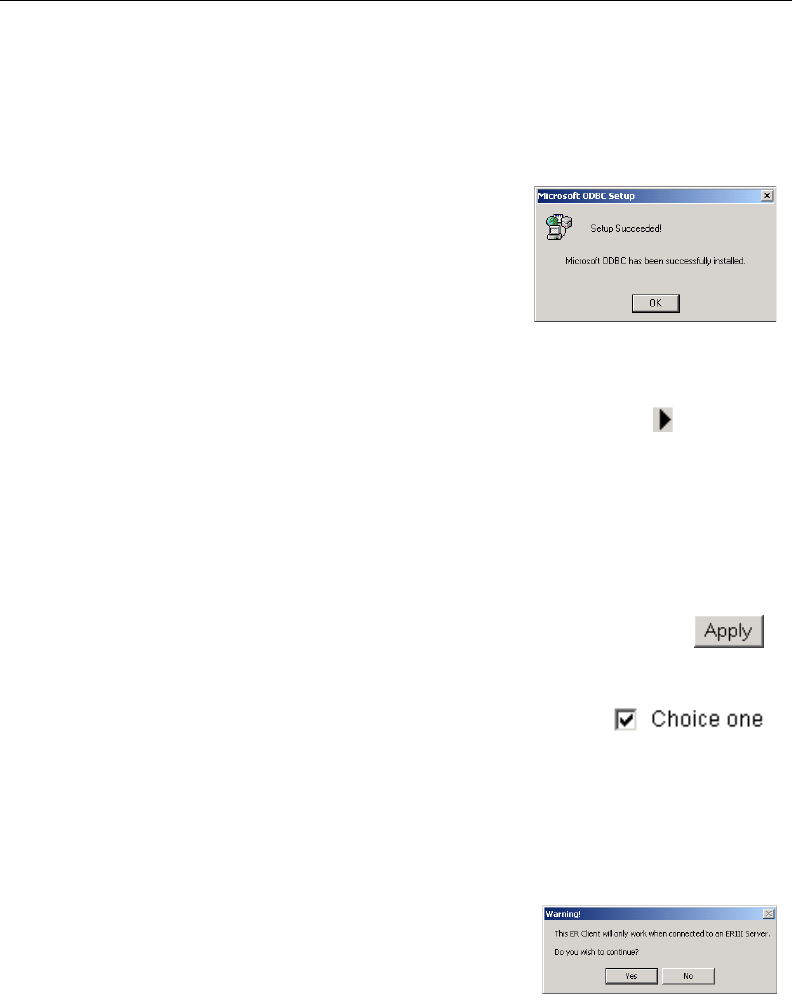
Install the ODBC Driver .................................................................. 77
Install Microsoft Access Runtime .................................................... 80
Download and Install the Client ......................................................82
Download the Client .................................................................82
Install the Client ........................................................................ 84
Update the Server Address and Password .........................89
Uninstall the Client, Install New Release ................................. 92
Chapter 2: Accessing the Client ........................................................94
Launch the Client Application ......................................................... 94
Login window .................................................................................. 94
Administrator Details ................................................................95
Change the Administrator Password...................................95

8E6 TECHNOLOGIES, ENTERPRISE REPORTER 3.0 USER’S GUIDE 7
CONTENTS
View, Modify Server Information ......................................... 96
Log In ....................................................................................... 99
Server Statistics ................................................................100
Date Scopes ................................................................100
Expiration Info ..............................................................101
ER Activity .................................................................... 101
Navigate the Main Menu ...................................................105
Buttons .........................................................................106
Icons.............................................................................106
Log Out...................................................................................107
Chapter 3: Customizing the Client................................................... 108
Settings .........................................................................................108
Event Schedule ...................................................................... 109
View Details or Edit a Scheduled Event ............................ 110
View Details for a Scheduled Event ............................. 110
Edit a Scheduled Event................................................ 111
Schedule an Event ............................................................ 112
Delete a Scheduled Event ................................................ 113
Category Descriptions ............................................................ 113
View Details for a Filter Category ...................................... 114
Update a Filter Category ................................................... 114
Add a Filter Category ........................................................ 115
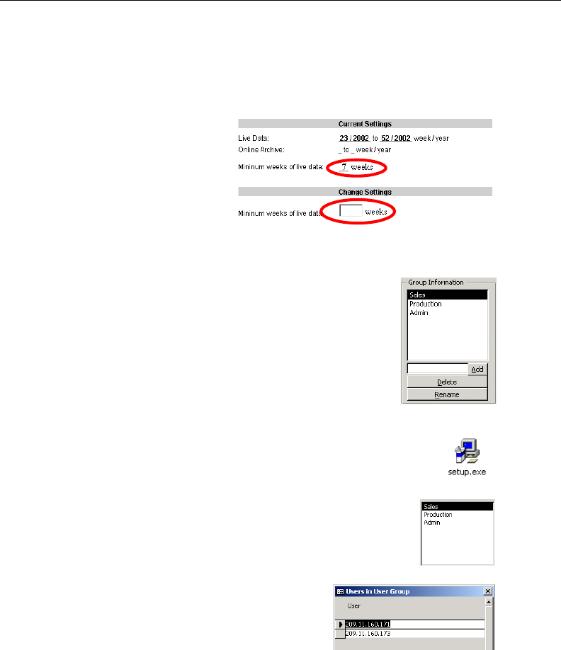
Category Groupings ............................................................... 116
Group Information frame ................................................... 117
Add a Category Group ................................................. 117
Rename a Category Group .......................................... 117
Delete a Category Group ............................................. 118
Group Definitions frame .................................................... 119
Add Categories to a Category Group........................... 119
Delete a Category from a Category Group ..................120
User Groupings ...................................................................... 121
Group Information frame ...................................................121
Add a User Group ........................................................122
Rename a User Group ................................................. 122
Delete a User Group .................................................... 123
Group Definitions frame ....................................................123
View a List of Users in a User Group ........................... 123
Define a User Group ....................................................124
Delete a User ...............................................................127

88E6 TECHNOLOGIES, ENTERPRISE REPORTER 3.0 USER’S GUIDE
CONTENTS
User Permissions ................................................................... 128
Add User ...........................................................................128
User Information frame .....................................................130
Add User to a User Group ...........................................130
Remove User from a User Group ................................ 130
Group Information frame ...................................................131
Update User Group by Adding a User .........................131
Update User Group by Removing a User .................... 131
Edit Password or Delete User ........................................... 131
Change a User’s Password .........................................132
Delete a User ...............................................................132
My Account .............................................................................133
View Users in a User Group.............................................. 134
Change Password ............................................................. 135
Default Options.......................................................................136
Set New Defaults ..............................................................136
Chapter 4: Using the Client ..............................................................137
Specific Search Function ..............................................................137
Specify Time Frame for the Search ........................................ 138
Specify Type of Search to be Performed ................................ 139
Specify Items to be Searched, View Results .......................... 139
Warning Messages ........................................................... 140
Page Search ................................................................140
Object Search ..............................................................140
View Additional Information ....................................................141
Report Screen Elements...............................................................142
Date Scope.............................................................................143
Display button......................................................................... 145
Search button ......................................................................... 146
Navigation path ...................................................................... 146
Navigation bar ........................................................................147
Back icon...........................................................................147
Categories icon ................................................................. 147
IPs icon .............................................................................148
Users icon ......................................................................... 148
Sites icon........................................................................... 148
Category Groups icon .......................................................148
User Groups icon ..............................................................148
Exit icon............................................................................. 149
Reports / Report Layout field ............................................149

8E6 TECHNOLOGIES, ENTERPRISE REPORTER 3.0 USER’S GUIDE 9
CONTENTS
Save icon ..........................................................................149
View icon ........................................................................... 150
View, Print the Report .................................................. 151
Double Break Information dialog box...........................152
Generate Chart box .....................................................153
Print icon ...........................................................................154
E-mail icon ........................................................................154
Export icon ........................................................................ 156
Record icon .......................................................................157
Save Custom Report dialog box .................................. 158
Save as Custom Report dialog box .............................160
Open a Recorded Report .............................................162
Filters......................................................................................164
Columns .................................................................................164
Select All, Deselect All buttons ...............................................167
Records ..................................................................................168
Generate a Report ........................................................................169
Report Formats ......................................................................170
Standard report .................................................................171
Pie Chart report ................................................................. 172
Bar Chart report ................................................................173
Chapter 5: Reports ............................................................................ 174
Categories Reports .......................................................................174
Categories ..............................................................................174
Category/IPs........................................................................... 175
Category/Users ......................................................................176
Category/Sites ........................................................................177
IPs Reports ...................................................................................178
IPs ..........................................................................................178
IP/Categories..........................................................................179
IP/Users.................................................................................. 180
IP/Sites ...................................................................................181
Users Reports ............................................................................... 182
Users ......................................................................................182
User/Categories .....................................................................183
User/IPs.................................................................................. 184
User/Sites ...............................................................................185
Sites Reports ................................................................................ 186
Sites .......................................................................................186
Site/Categories .......................................................................187

10 8E6 TECHNOLOGIES, ENTERPRISE REPORTER 3.0 USER’S GUIDE
CONTENTS
Site/IPs ...................................................................................188
Site/Users ...............................................................................189
Category Groups Report...............................................................190
User Groups Report......................................................................190
Page/Object Reports ....................................................................191
TECHNICAL SUPPORT / PRODUCT WARRANTIES SECTION 193
Technical Support .............................................................................193
Hours ............................................................................................ 193
Contact Information ......................................................................193
Domestic (United States)........................................................193
International............................................................................ 193
E-Mail .....................................................................................194
Address ..................................................................................194
Support Procedures ...................................................................... 194
Product Warranties ...........................................................................195
Standard Warranty ........................................................................195
Technical Support and Service ..................................................... 196
Extended Warranty (optional) ....................................................... 197
Extended Technical Support and Service ..................................... 197
APPENDICES SECTION ...................................................198
Appendix A......................................................................................... 198
Scheduled Task Wizard ................................................................198
Steps for Scheduling a Task ...................................................198
Appendix B ........................................................................................205
Lotus Notes Configuration ............................................................205
Steps for Former MS Outlook / Express Users ......................205
Steps for Installing and Configuring Lotus Notes ................... 206
Step 1: Install Lotus Notes ................................................ 206
Step 2: Configure Microsoft Mail Client .............................206
Step 3: Verify Internet Explorer Settings ........................... 206
INDEX.........................................................................207

8E6 TECHNOLOGIES, ENTERPRISE REPORTER 3.0 USER’S GUIDE 11
OVERVIEW
ENTERPRISE REPORTER 3.0 OVERVIEW
Though many companies have Internet filtering solutions
to prevent employees from accessing inappropriate, non-
work related Web sites, simply blocking these sites is not
enough. Administrators want the ability to know who is
accessing which site, the duration of each site visit, and the
frequency of these visits. This data can help administrators
identify abusers, develop policies, and target sites to be
filtered, in order to maximize bandwidth utilization and pro-
ductivity.
The Enterprise Reporter 3.0 (ER 3.0) from 8e6 Technologies
is designed to readily obtain this information, giving the user
the ability to interrogate massive datasets through flexible
drill-down technology, until the desired view is obtained. This
“view” can then be memorized and saved to a user-defined
report menu for repetitive, scheduled execution and distribu-
tion.
Operations
In simplified terms, the ER 3.0 operates as follows: the ER
3.0 Server box accepts log files (text files containing Web
access data) from a source device such as 8e6’s R2000
Standard Edition or Enterprise Edition, or the 8e6 R3000
Enterprise Filter. 8e6’s proprietary programs “normalize” the
transferred data and insert them into a MySQL database. The
ER 3.0 Client reporting application accesses this database to
generate a virtually unlimited number of queries and reports.

12 8E6 TECHNOLOGIES, ENTERPRISE REPORTER 3.0 USER’S GUIDE
OVERVIEW
Components
Hardware
• High performance server
• One or more high-capacity hard drives
• Optional: One or more Network Attached Storage (NAS)
devices
Software
•Linux OS
•Graphical User Interface (GUI) application utilized by
authorized administrators to configure and maintain the ER
3.0 Server
•8e6 Technologies proprietary programs for processing and
organizing files transferred via Web access logging
device(s)
•MySQL database
•MS Access Runtime
•8e6 Technologies proprietary application employed by
report users for generating “views” and reports

8E6 TECHNOLOGIES, ENTERPRISE REPORTER 3.0 USER’S GUIDE 13
OVERVIEW
Environment
Client Workstation Requirements
Minimum system requirements include the following:
•450 MHz CPU
•256 MB RAM
•1024 x 768 display
•1 GB free hard drive space
•Windows 98, 2000, NT 4.0, or XP operating system
•Internet Explorer (IE) Version 5.0 or later
Network Requirements
•High-speed connection from the ER 3.0 Server to the Web
access logging device(s)
•High-speed connection from the ER 3.0 Server to the
Client workstation(s)

14 8E6 TECHNOLOGIES, ENTERPRISE REPORTER 3.0 USER’S GUIDE
OVERVIEW
How to Use this Manual
Organization
This User’s Guide is organized into the following sections:
• Overview - This section provides information on the ER
3.0 application, and how to use this manual to help you
configure the ER 3.0 Server and Client.
• Administrator Section - Refer to this section for informa-
tion on configuring and maintaining the ER 3.0 Server via
the Administrator GUI application.
• Client User Section - This section includes information on
configuring and using the Client application.
• Tech Support / Product Warranties Section - This
section contains information on technical support and
product warranties.
• Appendices Section - Appendix A provides information on
using the Scheduled Task Wizard to schedule a report to
be generated at a specified time. Appendix B provides
information on configuring Lotus Notes to work with Client
application reports, instead of Microsoft Outlook.
• Index - This section includes an index of topics and the first
page numbers where they appear in this user’s guide.

8E6 TECHNOLOGIES, ENTERPRISE REPORTER 3.0 USER’S GUIDE 15
OVERVIEW
Conventions
The following icons are used throughout this User’s Guide:
NOTE: The “note” icon is followed by italicized text providing
additional information about the current topic.
TIP: The “tip” icon is followed by italicized text giving you hints
on how to execute a task more efficiently.
WARNING: The “warning” icon is followed by italicized text
cautioning you about making entries in the application, executing
certain processes or procedures, or the outcome of specified
actions.
16 8E6 TECHNOLOGIES, ENTERPRISE REPORTER 3.0 USER’S GUIDE
OVERVIEW
Terminology
The following terms are used throughout this User’s Guide.
Sample images (not to scale) are included for each item.
• alert box - a message box
that opens in response to an
entry you made in a dialog
box, window, or screen. This
box often contains a button
(usually labeled “OK”) for
you to click in order to
confirm or execute a command.
• arrow - a triangular-shaped object or button that dis-
plays in a window or on a screen. When displayed as a
non-stationary object, the arrow points to the item that was
selected in a list. When displayed as a button, the arrow is
static. By clicking on this button, depending on the direction
of the arrow, the previous item or the next item in a list
displays or is selected.
• button - an object in a dialog box, window, or
screen that can be clicked with your mouse to
execute a command.
• checkbox - a small square in a
dialog box, window, or screen used
for indicating whether or not you wish to select an option.
This object allows you to toggle between two choices. By
clicking in this box, a check mark or an “X” is placed,
indicating that you selected the option. When this box is not
checked, the option is not selected.
• dialog box - a box that opens
in response to a command
made in a window or screen,
and requires your input. You
must choose an option by
8E6 TECHNOLOGIES, ENTERPRISE REPORTER 3.0 USER’S GUIDE 17
OVERVIEW
clicking a button (such as “Yes” or “No”, or “Next” or “Can-
cel”) to execute your command. As dictated by this box, you
also might need to make one or more entries or selections
prior to clicking a button.
• field - an area
in a dialog
box, window,
or screen that
either accom-
modates your
data entry, or
displays pertinent information. A text box is a type of field.
• frame - a boxed-in area in a dialog box,
window, or screen that includes a group
of objects such as fields, text boxes, list
boxes, buttons, radio buttons, and/or
tables. Objects within a frame belong to
a specific function or group. A frame
often is labeled to indicate its function or
purpose.
• icon - a small image in a dialog box, window, or
screen that can be clicked. This object can be
a button or an executable file.
• list box - an area in a dialog box, window,
or screen that accommodates and/or
displays entries of items that can be added
or removed.
• popup box or popup win-
dow - a box or window that
opens after you click a button
in a dialog box, window, or
screen. This box or window
may display information, or may require you to make one or
more entries. Unlike a dialog box, you do not need to
choose between options.
18 8E6 TECHNOLOGIES, ENTERPRISE REPORTER 3.0 USER’S GUIDE
OVERVIEW
• pull-down menu - a field in a
dialog box, window, or screen that
contains a down-arrow to the right. When you click the
arrow, a menu of items displays from which you make a
selection.
• radio button - a small, circular
object in a dialog box, window, or
screen used for selecting an option. This object allows you
to toggle between two choices. By clicking a radio button, a
dot is placed in the circle, indicating that you selected the
option. When the circle is empty, the option is not selected.
• screen - a main object of
an application that dis-
plays across your monitor.
A screen can contain
windows, frames, fields,
tables, text boxes, list
boxes, icons, buttons, and
radio buttons.
• table - an area in a window or
screen that contains items
previously entered or se-
lected.
• text box - an area in a dialog
box, window, or screen that
accommodates your data entry. A text box is a type of field.
• window - displays on a
screen, and can contain
frames, fields, text
boxes, list boxes, icons,
buttons, and radio
buttons. Types of win-
dows include ones from
the system such as the
Save As window, popup windows, or login windows.

8E6 TECHNOLOGIES, ENTERPRISE REPORTER 3.0 USER’S GUIDE 19
ADMINISTRATOR SECTION: INTRODUCTION
ADMINISTRATOR SECTION
Introduction
The authorized administrator of the ER 3.0 Server is respon-
sible for integrating the Server into the existing network, and
providing the Server a high-speed connection to the desig-
nated logging device(s) and remote Client workstations. To
attain this objective, the administrator performs the following
tasks:
•executes Quick Start procedures defined in the four-page
Quick Start Guide leaflet packaged with the ER 3.0 Server
•provides a suitable environment for the Server, including:
• high speed, File Transfer Protocol (FTP) link to the
current logging device
• power connection protected by an Uninterruptible
Power Supply (UPS)
• high speed access to the Server by authorized Client
workstations
•adds new administrators
•sets up administrators for receiving automatic alerts
•updates the Server with patches supplied by 8e6
•analyzes Server statistics
•utilizes diagnostics for monitoring the Server status to
ensure optimum functioning of the Server
Instructions on configuring and maintaining the ER 3.0 Server
are documented in this section.
20 8E6 TECHNOLOGIES, ENTERPRISE REPORTER 3.0 USER’S GUIDE
ADMINISTRATOR SECTION: CHAPTER 1 - ACCESSING THE SERVER
Chapter 1: Accessing the Server
Preliminary Network Settings
To initially set up your ER 3.0 Server, follow the instructions in
the Quick Start Guide, the four-page leaflet packaged with
your ER 3.0. This guide explains how to perform the initial
configuration of the Server so that it can be accessed via an
IP address on your network.
NOTE: If you do not have the ER 3.0 Quick Start Guide,
contact 8e6 Technologies immediately to have a copy sent to
you.
Procedures for Accessing the Server
WARNING: Once you turn on the Server, DO NOT interrupt
the initial boot-up process. This process may take from five to 10
minutes per drive. If the process is interrupted, damage to key
files may occur.
When the Server is fully booted, any workstation on the
network that can access the Server’s IP address (set up
during Quick Start procedures) will be able to communicate
with the Server via the Internet.
1. Launch Internet Explorer (IE).
2. In the address line of the IE browser window, type in the
Server’s IP address. Port number “88” should be appended
to this IP address. For example, if your IP address is
1.2.3.4, type in http://1.2.3.4:88.
3. Click the Go button to open the login dialog box of the
Administrator GUI application.
8E6 TECHNOLOGIES, ENTERPRISE REPORTER 3.0 USER’S GUIDE 21
ADMINISTRATOR SECTION: CHAPTER 1 - ACCESSING THE SERVER
Procedures for Logging On, Off the Server
WARNING: In order to prevent data from being lost or
corrupted while the Server is running, the Server should be
connected to a UPS or other battery backup system.
Log On
1. In the login dialog box, type in the generic User Name
admin, and Password reporter, if you have not yet set up
your own user name and password. Otherwise, enter your
personal User Name and Password.
2. Click OK to close the login dialog box and to go to the main
screen of the Administrator GUI.
NOTE: When logging on the Server for the first time, the
main screen displays with a message, as shown in the example
in Logging on the First Time. Follow the directions in this sub-
section before proceeding.
If you are logging on during a subsequent session, the main
screen displays as in Fig. 1:2-1. If you have not set up your own
user name and password, see Set up an Administrator Login ID.
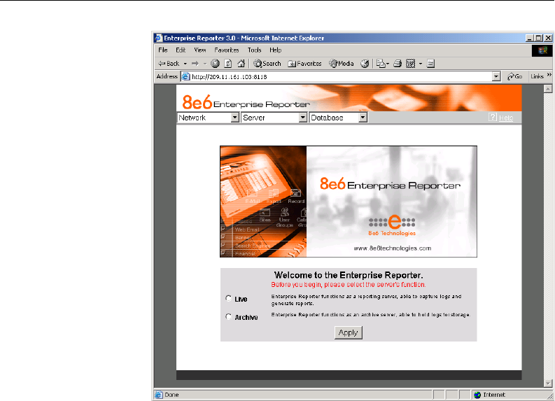
Logging on the First Time
If you are logging on the Administrator GUI for the first time,
the main screen displays with a message that asks you to
specify the Server’s function (Fig. 1:1-1):
22 8E6 TECHNOLOGIES, ENTERPRISE REPORTER 3.0 USER’S GUIDE
ADMINISTRATOR SECTION: CHAPTER 1 - ACCESSING THE SERVER
Specify the Server’s function
1. Click the appropriate radio button to specify the function of
the Server:
• choose Live if you wish the Server to function in the “live”
mode, receiving and processing real time data from the
Web access logging device.
• choose Archive if you wish the Server to function in the
“archive” mode, solely as a receptacle for historical,
archived files. In this mode, “old” files placed on the
Server can be viewed using the Client reporting applica-
tion.
2. Click Apply to confirm your selection. The mode you
specify will immediately be in effect.
Fig. 1:1-1 Administrator GUI, main screen, first-time access
8E6 TECHNOLOGIES, ENTERPRISE REPORTER 3.0 USER’S GUIDE 23
ADMINISTRATOR SECTION: CHAPTER 1 - ACCESSING THE SERVER
TIP: After choosing the function for the ER 3.0 Server box on
the main screen, if you have not previously set up your own user
name and password, you should do so before entering any
Server settings.
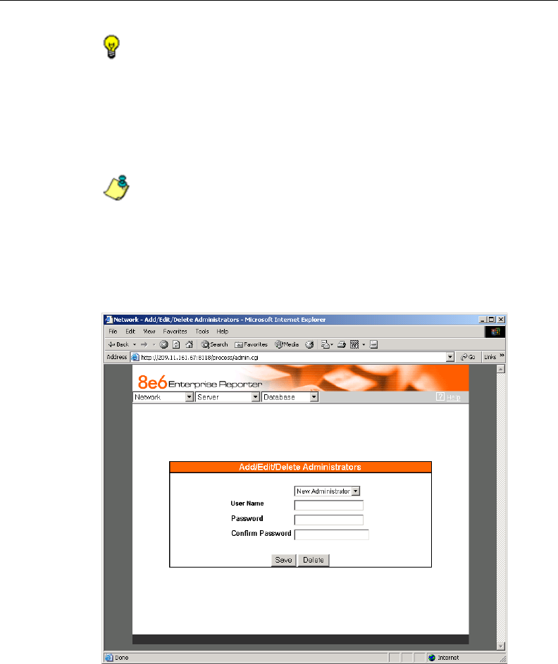
Set up an Administrator Login ID
NOTE: If you have already set up your user name and
password, you can skip this section.
1. At the Network pull-down menu, choose Administrators to
display the Add/Edit/Delete Administrators screen where
you will set up your user name and password:
Fig. 1:1-2 Add/Edit/Delete Administrators screen
24 8E6 TECHNOLOGIES, ENTERPRISE REPORTER 3.0 USER’S GUIDE
ADMINISTRATOR SECTION: CHAPTER 1 - ACCESSING THE SERVER
2. Select New Administrators from the pull-down menu.
3. In the User Name field, enter up to 20 upper- and/or
lowercase alphanumeric characters, without spaces.
4. In the Password field, enter up to eight alphanumeric
characters in upper- or lowercase characters, or a combi-
nation of both. The password is case sensitive. For security
purposes, an asterisk displays for each character entered.
5. In the Confirm Password field, re-enter the password in
the exact format used at the Password field. An asterisk
displays for each character entered at this field.
6. Click the Save button.
Log Off
To log off the Administrator GUI, click the in the upper right
corner of the browser window to close the window. Exiting the
Administrator GUI will log you off the Server, but will not turn
off the Server.
WARNING: If you need to turn off the Server, follow the shut
down procedures outlined in the Shut Down screen sub-section
under the Server Menu section in Chapter 2. Failure to properly
shut down the Server can result in data being lost or corrupted.
8E6 TECHNOLOGIES, ENTERPRISE REPORTER 3.0 USER’S GUIDE 25
ADMINISTRATOR SECTION: CHAPTER 2 - CONFIGURING THE ER 3.0 SERVER
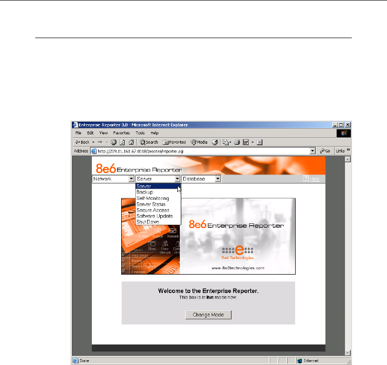
Chapter 2: Configuring the ER 3.0 Server
Administrator GUI
After logging on the Server, the main screen of the Adminis-
trator GUI displays in your Web browser:
The Administrator GUI is used for configuring and maintain-
ing the ER 3.0 Server. Settings made in the Administrator GUI
affect the Client reporting application. On the main screen of
the Administrator GUI, there are three menus: Network,
Server, and Database. Each menu contains options from
which you make selections to access screens used for
configuring your Server.
Fig. 1:2-1 Administrator GUI, main screen
26 8E6 TECHNOLOGIES, ENTERPRISE REPORTER 3.0 USER’S GUIDE
ADMINISTRATOR SECTION: CHAPTER 2 - CONFIGURING THE ER 3.0 SERVER
NOTE: The mode of the Server displays on the main screen.
More information about the “live” and “archive” Server box modes
can be found in the Box Mode sub-section under the Network
Menu section in this chapter.
TIP: When making a complete configuration of the Server, 8e6
Technologies recommends you navigate from left to right (Net-
work to Server to Database) in choosing your menu options.
Network Menu
The Network pull-down menu includes options for setting up
and maintaining components to be used on the Server’s
network. These options are: Box Mode, Administrators,
Network Setting, Routing Table, Time Setting, and Diagnos-
tics.
Fig. 1:2-2 Network menu, main screen

8E6 TECHNOLOGIES, ENTERPRISE REPORTER 3.0 USER’S GUIDE 27
ADMINISTRATOR SECTION: CHAPTER 2 - CONFIGURING THE ER 3.0 SERVER
Box Mode
The Server box mode displays by default when you first log
on the Server, or when the Box Mode option is selected from
the Network menu. (See Figs. 1:2-1 and 1:2-2.) The box
mode indicates whether the Server box is functioning in the
“live” mode, or in the “archive” mode. When the box mode
displays on the screen, you can view the current mode set for
the Server, and can change this setting, if necessary.
Live Mode
Once your Server is configured and the Server box is set in
the “live” mode, it will receive and process real time data from
the Web access logging device. The Client reporting applica-
tion can then be used to capture data and create views.
Archive Mode
In the “archive” mode, the Server box solely functions as a
receptacle in which historical, archived files are placed. In this
mode, “old” files placed on the Server can be viewed using
the Client reporting application.
28 8E6 TECHNOLOGIES, ENTERPRISE REPORTER 3.0 USER’S GUIDE
ADMINISTRATOR SECTION: CHAPTER 2 - CONFIGURING THE ER 3.0 SERVER
Change the Box Mode
1. Click the Change Mode button to display the two box mode
options on the screen:
2. Click the radio button corresponding to Live or Archive to
specify the mode in which the Server should function.
3. Click the Apply button to confirm your selection. The “new”
mode will be in effect after the Server is restarted.
NOTE: After applying the box mode setting, you must restart
the Server by selecting the Restart Hardware option on the Shut
Down screen. (See the Shut Down sub-section under the Server
menu section in this chapter.)
Fig. 1:2-3 Change Box Mode
8E6 TECHNOLOGIES, ENTERPRISE REPORTER 3.0 USER’S GUIDE 29
ADMINISTRATOR SECTION: CHAPTER 2 - CONFIGURING THE ER 3.0 SERVER
Add/Edit/Delete Administrators screen
The Add/Edit/Delete Administrators screen displays when the
Administrators option is selected from the Network menu.
This screen is used for viewing, adding, editing, and deleting
the login ID of personnel authorized to configure the Server.
For security purposes, administrators should be the first
users set up on the Server.
TIP: 8e6 recommends adding an alternate login ID prior to
editing or deleting the default login ID. By doing so, if one login ID
fails, you have another you can use.
Fig. 1:2-4 Add/Edit/Delete Administrators screen

30 8E6 TECHNOLOGIES, ENTERPRISE REPORTER 3.0 USER’S GUIDE
ADMINISTRATOR SECTION: CHAPTER 2 - CONFIGURING THE ER 3.0 SERVER
View a List of Administrators
To view a list of administrator user names, click the down
arrow at the New Administrator field. If no administrator has
yet been assigned to the Server, no selections display except
for the default “admin” user name.
Add an Administrator
1. Select New Administrator from the pull-down menu.
2. In the User Name field, enter up to 20 upper- and/or
lowercase alphanumeric characters, without spaces, for
the administrator’s name.
3. In the Password field, enter up to eight characters for the
administrator’s password. The entry in this field is alphanu-
meric and case sensitive. For security purposes, an aster-
isk displays for each character entered in this field.
3. In the Confirm Password field, re-enter the password in
the exact format used in the Password field. An asterisk
displays for each character entered in this field.
4. Click the Save button to add the administrator to the
choices in the pull-down menu.
Edit an Administrator’s Login ID
1. Select the administrator’s user name from the pull-down
menu.
2. Edit either of the following fields:
• User Name
• Password (if this field is edited, the Confirm Password
field must be edited in tandem)
3. Click the Save button.
8E6 TECHNOLOGIES, ENTERPRISE REPORTER 3.0 USER’S GUIDE 31
ADMINISTRATOR SECTION: CHAPTER 2 - CONFIGURING THE ER 3.0 SERVER
Delete an Administrator
1. Select the administrator’s user name from the pull-down
menu.
2. After the administrator’s login ID information populates the
fields, click the Delete button to remove the administrator’s
user name from the choices in the pull-down menu.
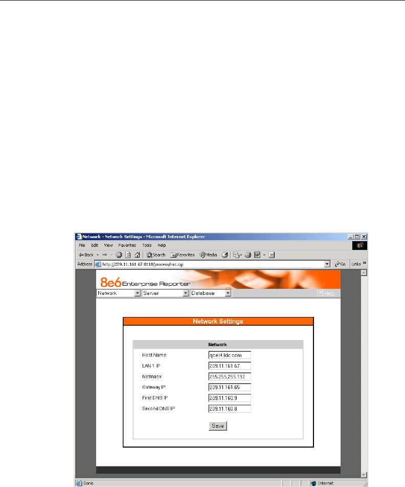
Network Settings screen
The Network Settings screen displays when the Network
Setting option is selected from the Network menu. This
screen is used for setting up IP addresses so the Server can
communicate with your system.
Fig. 1:2-5 Network Settings screen

32 8E6 TECHNOLOGIES, ENTERPRISE REPORTER 3.0 USER’S GUIDE
ADMINISTRATOR SECTION: CHAPTER 2 - CONFIGURING THE ER 3.0 SERVER
Set up/Edit IP Addresses
TIP: In order for the Server to effectively communicate with
your system, be sure all fields contain accurate information
before saving your settings.
1. Enter or edit an IP address in each appropriate field:
• In the Host Name field, enter the address or URL that will
be used for accessing the Administrator GUI. This entry
should include the full, qualified domain name, and the
“host” name for the box (i.e. reporter.myserver.com).
• In the LAN 1 IP field, enter the IP address of the ER 3.0
Server on your Local Area Network (LAN 1).
• In the Netmask field, enter the netmask that will define
the traffic designated for the LAN.
• In the Gateway IP field, enter the IP address for the
default router that will be the main gateway for the entire
network segment.
• In the First DNS IP field, enter the IP address of the
primary Domain Name System (name server). The
Server box will use this IP address to identify other IP
addresses on the system, including its own IP address.
• In the Second DNS IP field, enter the IP address of the
fallback DNS.
2. Be sure each IP address is correct, and then click Save.
NOTE: After appropriate entries have been made in these
fields and saved, you must restart the Server to activate the IPs.
To restart the Server, select the Restart Hardware option on the
Shut Down screen. (See the Shut Down sub-section under the
Server menu section in this chapter.)
8E6 TECHNOLOGIES, ENTERPRISE REPORTER 3.0 USER’S GUIDE 33
ADMINISTRATOR SECTION: CHAPTER 2 - CONFIGURING THE ER 3.0 SERVER
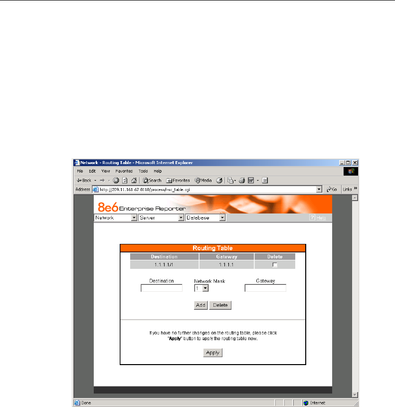
Routing Table screen
The Routing Table screen displays when the Routing Table
option is selected from the Network menu. This screen is
used for viewing, building, and maintaining a list of routers—
network destination and gateway IP addresses—the Server
will use for communicating with other segments of the net-
work. You will only need to set up a routing table if your local
network is interconnected with another network.
View a List of Routers
Each router that was configured in the routing table displays
as a separate row in the table. The IP address and subnet
mask to receive data packets display in the Destination
Fig. 1:2-6 Routing Table screen

34 8E6 TECHNOLOGIES, ENTERPRISE REPORTER 3.0 USER’S GUIDE
ADMINISTRATOR SECTION: CHAPTER 2 - CONFIGURING THE ER 3.0 SERVER
column, and the IP address of the portal that will transfer data
packets to and from the Internet displays in the Gateway
column.
Add a Router
1. In the Destination field, enter the IP address of the net-
work to which data packets will be forwarded.
2. At the Network Mask pull-down menu, specify the number
(1-32) of the subnet mask that will be used for grouping IP
addresses on the same local network.
3. In the Gateway field, enter the IP address of the portal to
which data packets will be transferred to and from the
Internet.
4. Click the Add button to include your entry in the table. If you
have another router to add, follow steps 1-4.
5. After you have entered all routers, click the Apply button to
display the confirmation screen indicating that your up-
dated routing table is now being applied to the Administra-
tor GUI.
6. Click the Back button on the confirmation screen to return
to the Routing Table screen.
Delete a Router
1. Click in the Delete checkbox of the row corresponding to
the router you wish to remove from the routing table.
2. Click the Delete button.
3. Click the Apply button to display the confirmation screen
indicating that your updated routing table is now being
applied to the Administrator GUI.
4. Click the Back button on the confirmation screen to return
to the Routing Table screen.
8E6 TECHNOLOGIES, ENTERPRISE REPORTER 3.0 USER’S GUIDE 35
ADMINISTRATOR SECTION: CHAPTER 2 - CONFIGURING THE ER 3.0 SERVER
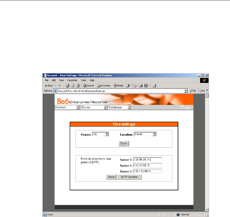
Time Settings screen
The Time Settings screen displays when the Time Setting
option is selected from the Network menu. This screen is
used for specifying the time zone and network time to be
used by the Server when generating reports via the Client
application.
Specify the Time Zone
1. At the Region pull-down menu, select your country from
the available choices.
2. If necessary, at the Location pull-down menu, select the
time zone for the specified region. A selection from this
menu is required if your Server is located in the United
States or in the Pacific Islands.
Fig. 1:2-7 Time Settings screen

36 8E6 TECHNOLOGIES, ENTERPRISE REPORTER 3.0 USER’S GUIDE
ADMINISTRATOR SECTION: CHAPTER 2 - CONFIGURING THE ER 3.0 SERVER
3. Click the Save button.
WARNING: The time zone set for the ER 3.0 should be the
same one set for each Web access logging device to be used by
the ER 3.0. These “like” settings ensure consistency when
tracking the logging times of all users on the network.
Specify Network Time Protocol Servers
IP addresses of servers running Network Time Protocol
(NTP) software are entered in the Server fields. NTP is a time
synchronization system for computer clocks throughout the
Internet. Your ER 3.0 Server will use the actual time from
clocks at the IP addresses you’ve specified.
1. Enter or edit an IP address in each appropriate field:
• In the Server 1 field, enter the IP address of the primary
NTP server to be used for clock settings on your Server.
• In the Server 2 field, enter the IP address of the second-
ary NTP server. The time from this server will be used by
your Server if the IP address for the primary server fails
to be accessed by your Server.
• In the Server 3 field, enter the IP address of the tertiary
NTP server. The time from this server will be used by
your Server if the IP addresses for the primary and
secondary servers fail to be accessed by your Server.
2. Click the Save button to save your entries.
NOTE: When you click the Save button, the IP addresses
you entered are saved, but the time on your Server will not be
synchronized with the NTP servers until you click the NTP Update
button.
8E6 TECHNOLOGIES, ENTERPRISE REPORTER 3.0 USER’S GUIDE 37
ADMINISTRATOR SECTION: CHAPTER 2 - CONFIGURING THE ER 3.0 SERVER
Update the Time on the Server
After you have saved the IP addresses of NTP servers you
wish your Server to access, click the NTP Update button to
synchronize the clock on your Server with the NTP server
clocks.
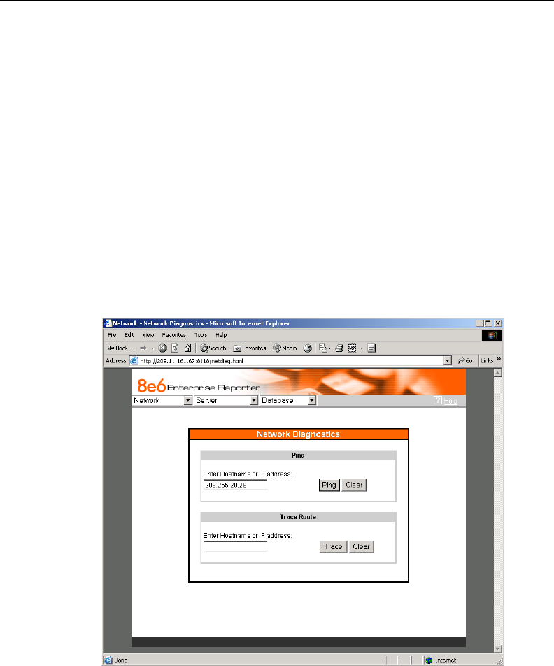
Network Diagnostics screen
The Network Diagnostics screen displays when the Diagnos-
tics option is selected from the Network menu. This screen is
used to help you identify and resolve problems with your
network configuration, using the ping and trace route utility
tools.
Fig. 1:2-8 Network Diagnostics screen, Ping entry
38 8E6 TECHNOLOGIES, ENTERPRISE REPORTER 3.0 USER’S GUIDE
ADMINISTRATOR SECTION: CHAPTER 2 - CONFIGURING THE ER 3.0 SERVER
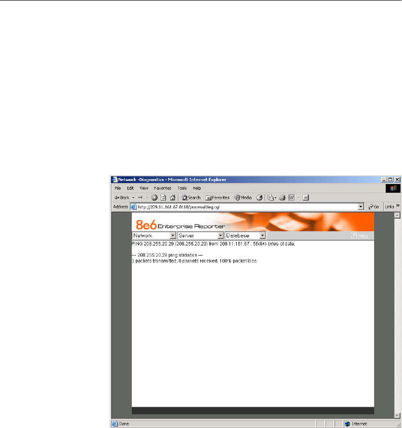
Ping
The ping utility is used for verifying whether the Server can
communicate with a machine at a given IP address within the
network, and the speed of the network connection.
1. In the Ping frame, enter the IP address or host name of the
specific Internet address to be contacted (pinged).
2. Click the Ping button to display the results found by the
Server, as shown on the sample screen:
As indicated by the results for the sample entry, the Server at
206.255.20.29 was not able to communicate with the ma-
chine at the IP address 209.11.161.67. The statistics show
that three (3) data packets were transmitted by the Server,
Fig. 1:2-9 Ping results

8E6 TECHNOLOGIES, ENTERPRISE REPORTER 3.0 USER’S GUIDE 39
ADMINISTRATOR SECTION: CHAPTER 2 - CONFIGURING THE ER 3.0 SERVER
but zero (0) packets were received by the designated ma-
chine, for a total of three (3) errors and a 100 percent packet
loss.
TIP: If the machine cannot be contacted, be sure the ping
feature on that machine is turned on.
NOTE: To ping another IP address, click the Back button in
your browser window, then click the Clear button in the Ping
frame, and follow the procedures documented in this sub-section.
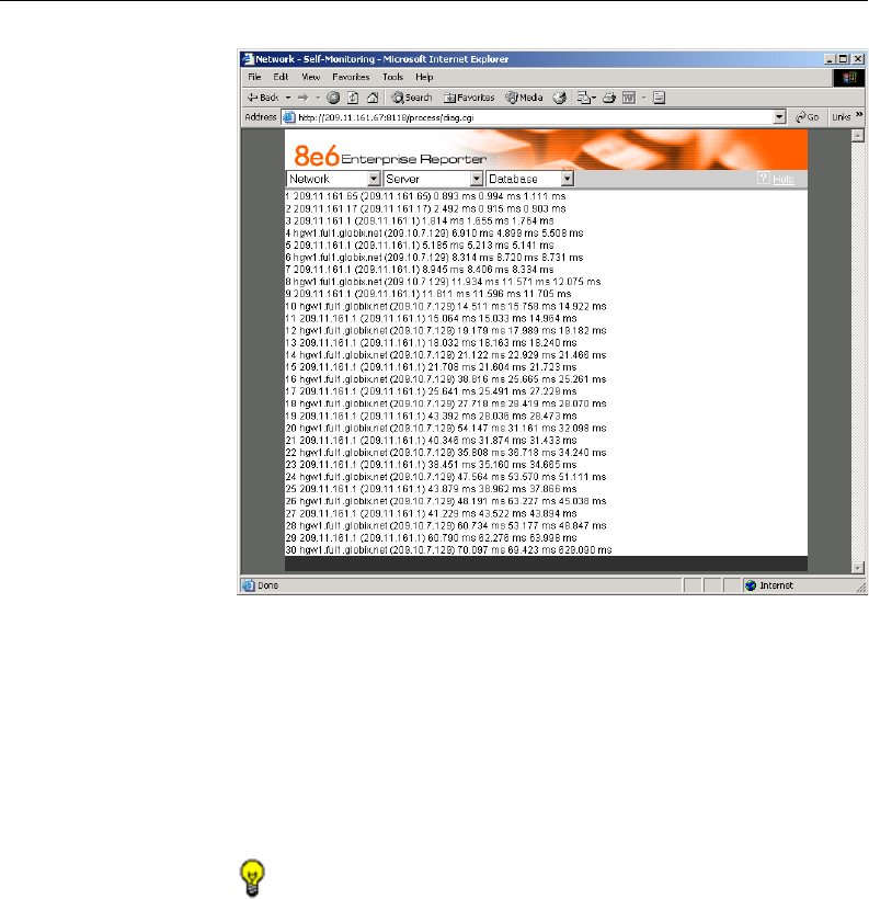
Trace Route
If the ping utility was not able to help you diagnose the prob-
lem with your network configuration, you should use the trace
route utility. This diagnostic tool records each “hop” (trip from
one router to another) the data packet made, identifying the
IP addresses of gateway computers where the packet
stopped en route to its final destination, and the length of time
of each hop.
NOTE: The trace route utility can be used after your routing
table has been set up. To set up a routing table, see the Routing
Table screen sub-section under the Network menu in this chap-
ter.
1. In the Trace Route frame, enter the IP address or host
name of the specific Internet address to be validated.
2. Click the Trace button to display the results found by the
Server, as shown on the sample screen:
40 8E6 TECHNOLOGIES, ENTERPRISE REPORTER 3.0 USER’S GUIDE
ADMINISTRATOR SECTION: CHAPTER 2 - CONFIGURING THE ER 3.0 SERVER
As indicated by the results for the sample entry, the packet
made 30 hops. For each line in the report, the hop number
displays, followed by the IP address or host name; the IP
address in parentheses; and the maximum, minimum, and
average response time in milliseconds.
TIP: To “trace” another IP address, click the Back button in
your browser window, then click the Clear button in the Trace
Route frame, and follow the procedures documented in this sub-
section.
Fig. 1:2-10 Trace Route results
8E6 TECHNOLOGIES, ENTERPRISE REPORTER 3.0 USER’S GUIDE 41
ADMINISTRATOR SECTION: CHAPTER 2 - CONFIGURING THE ER 3.0 SERVER
Server Menu
The Server pull-down menu includes options for setting up
processes for maintaining the Server. These options are:
Backup, Self-Monitoring, Server Status, Secure Access,
Software Update, and Shut Down.
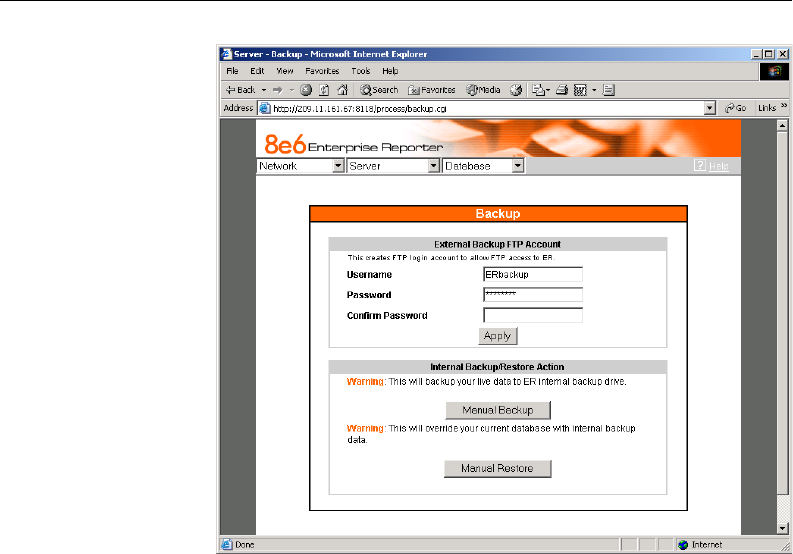
Backup screen
The Backup screen displays when the Backup option is
selected from the Server menu. This screen is used for
setting up the password for the remote server’s FTP account,
for executing an immediate backup on the ER 3.0 Server, and
for performing a restoration to the database from the previous
backup run.
Fig. 1:2-11 Server menu, main screen
42 8E6 TECHNOLOGIES, ENTERPRISE REPORTER 3.0 USER’S GUIDE
ADMINISTRATOR SECTION: CHAPTER 2 - CONFIGURING THE ER 3.0 SERVER
Backup Procedures
Although automatic backups to a local ER 3.0 hard drive are
scheduled nightly by default, it is important that the ER 3.0
administrator implements a backup policy to ensure data
integrity and continuity in the event of any possible failure
scenario. This policy should include frequent, remote back-
ups, such that raw logs and ER 3.0 database files are avail-
able for restoration without relying on the ER 3.0’s hard
drives.
In general, recovery plans involve (i) restoring the most
recent backup of the database, and (ii) restoring raw logs to
fill in the gap between the most recent backup of the data-
base, and the current date and time.
Fig. 1:2-12 Backup screen

8E6 TECHNOLOGIES, ENTERPRISE REPORTER 3.0 USER’S GUIDE 43
ADMINISTRATOR SECTION: CHAPTER 2 - CONFIGURING THE ER 3.0 SERVER
Some scenarios and action plans to consider include the
following:
• The ER 3.0 database becomes corrupted - Correct the
root problem. Restore the database from the most recent
ER 3.0 backup, and reprocess raw logs up to the current
date and time.
• The data drive fails - Replace the data drive. Restore the
database from the ER 3.0 backup drive, and reprocess raw
logs up to the current date and time.
• The backup drive fails - Replace the backup drive, and
perform a manual backup.
• Both data and backup drives are damaged - Restore the
database from the most recent remote backup, and repro-
cess raw logs up to the current date and time.
As you can see, it is critical that raw logs are available to
bridge the gap between the last database backup and the
present time, and more frequent backups (local and remote)
result in less “catch-up” time required for reprocessing raw
logs.
Set up/Edit External Backup FTP Password
In order to back up the ER 3.0 Server’s database to a remote
server, an FTP account must be established for the remote
server.
NOTE: In the External Backup FTP Account frame, the login
name that will be used to access the remote server displays in the
Username field. This field cannot be edited.
1. In the Password field, enter up to eight characters for the
password. The entry in this field is alphanumeric and case
sensitive. For security purposes, an asterisk displays for
each character entered.
44 8E6 TECHNOLOGIES, ENTERPRISE REPORTER 3.0 USER’S GUIDE
ADMINISTRATOR SECTION: CHAPTER 2 - CONFIGURING THE ER 3.0 SERVER
2. In the Confirm Password field, re-enter the password in
the exact format used in the Password field. An asterisk
displays for each character entered in this field.
3. Click the Apply button to save your entries. The updated
Account ID will be activated after two minutes.
Execute a Manual Backup
In addition to performing on demand backups in preparation
for a disaster recovery, you may wish to execute a manual
backup under the following circumstances:
• Power outage - If there is a power outage at your facility
and your system uses a backup battery, you might want to
back up data before the battery fails.
• Rolling blackout - If your facility is subjected to rolling
blackouts, and a blackout is scheduled during the time of
your daily backup, you should back up your data before the
blackout period, when the ER 3.0 Server will be down.
• Expiration about to occur - If a data expiration is about to
occur, you might want to back up your data before losing
the oldest data on the ER 3.0 Server, prior to the daily
backup process.
WARNING: If corrupted data is detected on the ER 3.0
Server, do not backup your data, as you may back up and eventu-
ally restore a corrupted database.
When performing a manual backup, the ER 3.0’s database is
immediately saved to the internal backup drive. From the
remote server, the backup database can be retrieved via FTP,
and then stored off site.
TIP: 8e6 recommends executing an on demand backup
during the lightest period of system usage, so the Server will
perform at maximum capacity.

8E6 TECHNOLOGIES, ENTERPRISE REPORTER 3.0 USER’S GUIDE 45
ADMINISTRATOR SECTION: CHAPTER 2 - CONFIGURING THE ER 3.0 SERVER
1. Click the Manual Backup button in the Internal Backup/
Restore Action frame to specify that you wish to back up
live data to the ER 3.0 Server’s internal backup drive.
2. On the Confirm Backup/Restore screen, click the Yes
button to back up the database tables and indexes.
WARNING: 8e6 recommends that you do not perform other
functions on the ER 3.0 Server until the backup is complete. The
time it will take to complete the backup depends on the size of all
tables being saved.
Perform a Remote Backup
After executing the manual backup, a remote backup can be
performed on your remote server.
NOTE: Before beginning this FTP process, be sure you have
enough space on the remote server for storing backup data. The
required space can be upwards of 200 gigabytes.
1. Log in to your FTP account.
2. Use FTP to download the ER 3.0 Server’s backup data-
base to the remote server.
3. Store this backup data in a safe place off the remote server.
If this backup database needs to be restored, it can be
uploaded to the ER 3.0 Server via FTP. (See Perform a
Restoration to the Server.)

46 8E6 TECHNOLOGIES, ENTERPRISE REPORTER 3.0 USER’S GUIDE
ADMINISTRATOR SECTION: CHAPTER 2 - CONFIGURING THE ER 3.0 SERVER
Perform a Restoration to the ER 3.0 Server
There are two parts in performing a restoration of data to your
ER 3.0 Server. Part one requires data to be loaded on the
remote server and then FTPed to the ER 3.0 Server. Part two
requires the FTPed data to be restored on the ER 3.0 Server.
NOTE: Before restoring backup data to the ER 3.0 Server,
be sure you have enough space on the ER 3.0 Server. Data that
is restored to the ER 3.0 Server will automatically include in-
dexes.
Perform these steps on the remote server:
1. Load the backup data on your remote server.
2. Log in to your FTP account.
3. FTP the backup data to the ER 3.0 Server’s internal backup
drive.
On the ER 3.0 Server’s Backup screen:
1. Click the Manual Restore button in the Internal Backup/
Restore Action frame to specify that you wish to overwrite
data on the live ER 3.0 Server with data from the previous,
internal backup run.
2. On the Confirm Backup/Restore screen, click the Yes
button to restore database tables and indexes to the ER 3.0
Server.
NOTE: The amount of time it will take to restore data to the
ER 3.0 Server depends on the combined size of all database
tables being restored. 8e6 recommends that you do not perform
other functions on the ER 3.0 Server until the restoration is
complete.

8E6 TECHNOLOGIES, ENTERPRISE REPORTER 3.0 USER’S GUIDE 47
ADMINISTRATOR SECTION: CHAPTER 2 - CONFIGURING THE ER 3.0 SERVER
Fig. 1:2-13 Self Monitoring screen
Self Monitoring screen
The Self Monitoring screen displays when the Self-Monitoring
option is selected from the Server menu. This screen is used
for setting up and maintaining e-mail addresses of contacts
who will receive automated notifications if problems occur
with the network. Possible alerts include situations in which a
daemon stops running, software fails to run, corrupted files
are detected, or a power outage occurs.
As the administrator of the Server, you have the option to
either activate or deactivate this feature. When the self-
monitoring feature is activated, an automated e-mail mes-
sage is dispatched to designated recipients if the Server
identifies a failed process during its hourly check for new
data.

48 8E6 TECHNOLOGIES, ENTERPRISE REPORTER 3.0 USER’S GUIDE
ADMINISTRATOR SECTION: CHAPTER 2 - CONFIGURING THE ER 3.0 SERVER
View a List of Contact E-Mail Addresses
If this feature is currently activated, the e-mail address of the
Master Administrator displays on this screen, along with any
other contacts set up as Choice one - four.
Set up and Activate Self-Monitoring
1. Click the radio button corresponding to YES.
2. Enter the Master Administrator’s E-Mail Address.
3. In the Send e-mail to e-mail address fields, enter up to
four e-mail addresses of persons authorized to receive
automated notifications. Entries in any of these four fields
are optional.
4. If e-mail addresses were entered in any of the four optional
e-mail address fields, click in the Choice one - Choice
four checkboxes corresponding to the e-mail address(es).
5. Click the Save button to activate self-monitoring.
Remove Recipient from E-mail Notification List
1. To stop sending emergency notifications to an e-mail
address set up in the list, remove the check mark from the
checkbox corresponding to the appropriate e-mail ad-
dress.
2. Click the Save button to remove the recipient’s name from
the e-mail list. The Master Administrator and any remaining
e-mail addresses in the list will continue receiving notifica-
tions.
Deactivate Self-Monitoring
1. Click the radio button corresponding to NO.
2. Click the Save button to deactivate self-monitoring.
8E6 TECHNOLOGIES, ENTERPRISE REPORTER 3.0 USER’S GUIDE 49
ADMINISTRATOR SECTION: CHAPTER 2 - CONFIGURING THE ER 3.0 SERVER
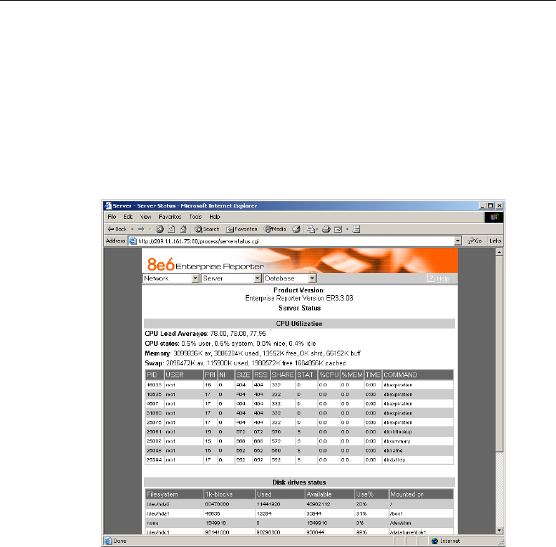
Server Status screen
The Server Status screen displays when the Server Status
option is selected from the Server menu. This screen, which
automatically refreshes itself every 10 seconds, displays the
statuses of processes currently running on the Server, and
provides information on the amount of space and memory
used by each process.
View the Status of the Server
The Product Version number of the software displays at the
top of the screen. Status information displays in the following
sections of this screen:
Fig. 1:2-14 Server Status screen
50 8E6 TECHNOLOGIES, ENTERPRISE REPORTER 3.0 USER’S GUIDE
ADMINISTRATOR SECTION: CHAPTER 2 - CONFIGURING THE ER 3.0 SERVER
•CPU Utilization - includes CPU process data and informa-
tion on the status of the top command
•Disk drives status - provides data on the status of each
drive of the operating system
•NETSTAT - displays the status of a local IP address
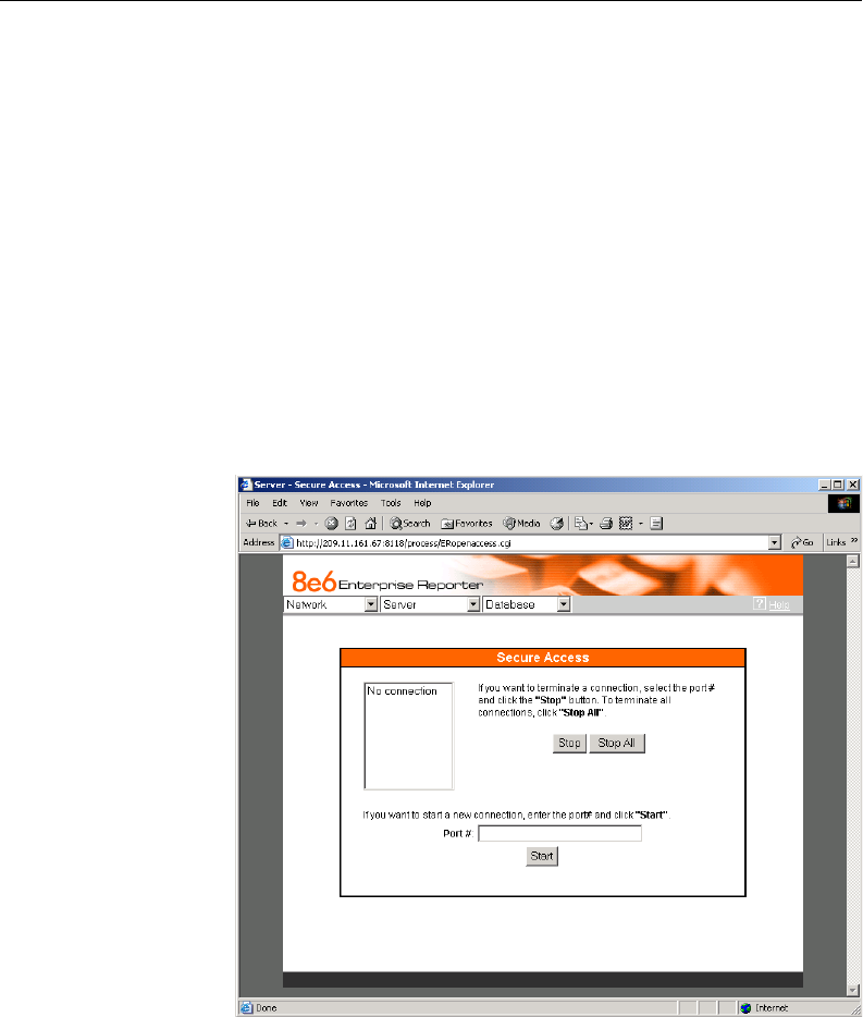
Secure Access screen
The Secure Access screen displays when the Secure Access
option is selected from the Server menu. This screen is
primarily used by 8e6 technical support representatives to
perform maintenance on your Server, if your system is behind
a firewall that denies access to your Server.
Fig. 1:2-15 Secure Access screen
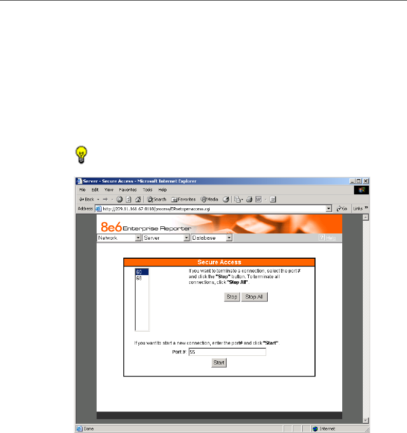
8E6 TECHNOLOGIES, ENTERPRISE REPORTER 3.0 USER’S GUIDE 51
ADMINISTRATOR SECTION: CHAPTER 2 - CONFIGURING THE ER 3.0 SERVER
Activate a Port to Access the Server
1. After the administrator at the customer’s site authorizes
you to use a designated port to access their Server, enter
that number at the Port # field.
2. Click the Start button to activate the port. This action enters
the port number in the list box above, replacing the text: “No
connection”.
TIP: Follow steps 1-2 to activate additional ports.
Terminate a Port Connection
1. After maintenance has been performed on the customer’s
Server, select the active port number from the list box by
clicking on it.
Fig. 1:2-16 Port entries
52 8E6 TECHNOLOGIES, ENTERPRISE REPORTER 3.0 USER’S GUIDE
ADMINISTRATOR SECTION: CHAPTER 2 - CONFIGURING THE ER 3.0 SERVER
2. Click the Stop button to terminate the port connection. This
action removes the port number from the list box.
Terminate All Port Connections
If more than one port is currently active on the customer’s
Server and you need to terminate all port connections, click
the Stop All button. This action removes all port numbers
from the list box.
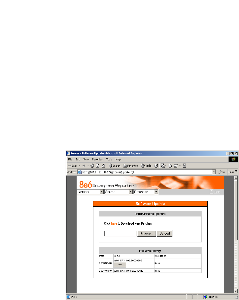
Software Update screen
The Software Update screen displays when the Software
Update option is selected from the Server menu. This screen
is used for updating the Server with software updates
(patches) supplied by 8e6.
Fig. 1:2-17 Software Update screen

8E6 TECHNOLOGIES, ENTERPRISE REPORTER 3.0 USER’S GUIDE 53
ADMINISTRATOR SECTION: CHAPTER 2 - CONFIGURING THE ER 3.0 SERVER
View Installed Patches
Any patch previously installed on the Server displays in the
ER Patch History frame. For each installed patch, the Date
installed (YYYY/MM/DD), and patch Name and Description
display.
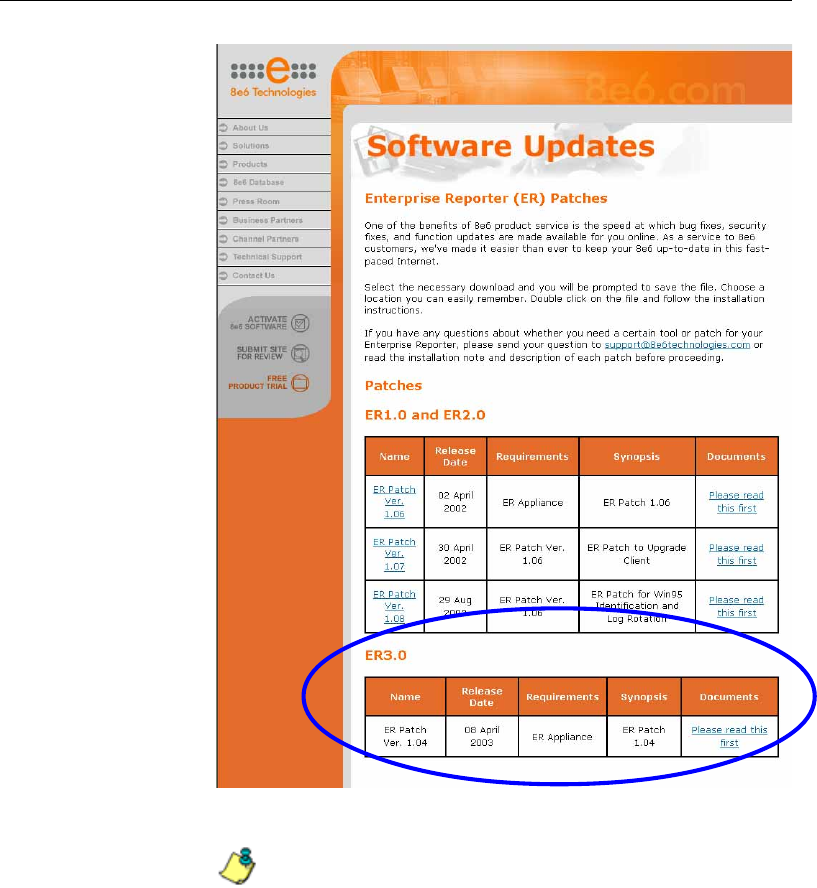
Retrieve a Patch
1. In the Retrieve Patch Updates frame, click the hyperlink
(“here”) to launch a browser window for the Web page
“Software Updates: Enterprise Reporter (ER) Patches”
(http://www.8e6technologies.com/patches/er.html) from
8e6’s Web site (see Fig. 1:2-18).
2. If patches are available for the ER 3.0, links to the files
display in the “ER 3.0” section of the Web page. To down-
load a patch to the Server, make a selection by clicking on
the Name of the patch.
3. In the Save As popup window, save the patch to a desig-
nated folder on the Server, then close the popup window
and the Web page.
Install a Patch
WARNING: Before installing a patch you must shut off the
Server’s software by selecting the Shutdown Software option on
the Shut Down screen. (See the Shut Down sub-section under
the Server menu section in this chapter.) All patches must be
installed in numerical order on your Server.
1. On the Software Update screen, click the Browse button to
open the Choose file popup window.
2. Select the patch. When you make a selection from this
popup window, the popup window closes and your choice
displays in the text box.
3. Click the Upload button to install the patch on the Server.
54 8E6 TECHNOLOGIES, ENTERPRISE REPORTER 3.0 USER’S GUIDE
ADMINISTRATOR SECTION: CHAPTER 2 - CONFIGURING THE ER 3.0 SERVER
NOTES: After installing the patch, you must restart the
Software by selecting the Restart Software option on the Shut
Down screen.
A patch can be uninstalled by clicking the Undo button beside the
patch in the Name column of the ER Patch History frame.
Fig. 1:2-18 Software Updates for the ER 3.0
8E6 TECHNOLOGIES, ENTERPRISE REPORTER 3.0 USER’S GUIDE 55
ADMINISTRATOR SECTION: CHAPTER 2 - CONFIGURING THE ER 3.0 SERVER
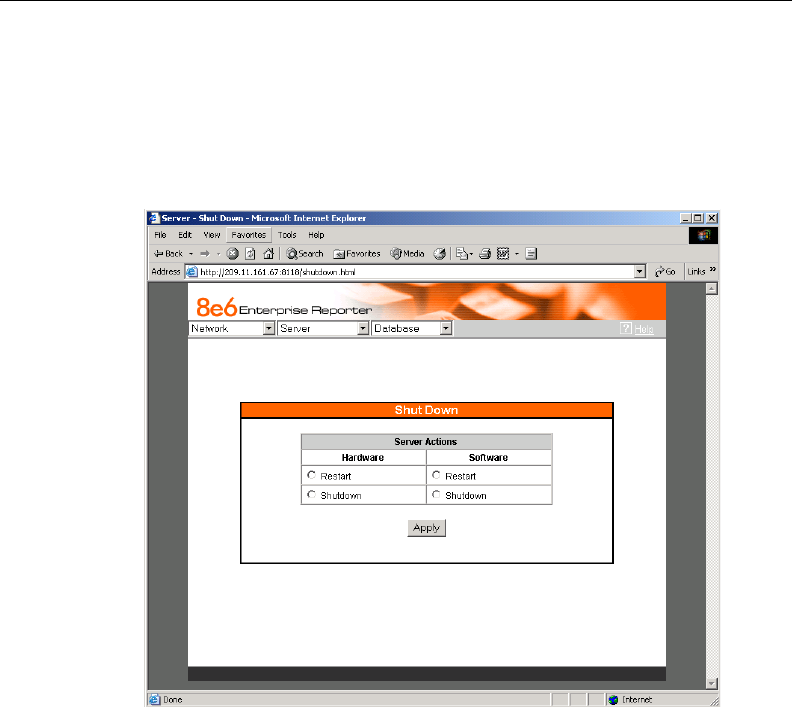
Shut Down screen
The Shut Down screen displays when the Shut Down option
is selected from the Server menu. This screen is used to
restart or shut down the Server’s software or hardware.
Server Action Selections
• Restart the Server’s Hardware - The Restart Hardware
option should be selected if the Server box needs to be
rebooted—for example, when applying certain hardware
configurations. You will need to use this option if the box
mode has been changed or after an IP address has been
entered in the Network Settings screen. During the Hard-
ware Restart process, files normally FTPed to the Server
are routed to a problem directory in the logging device.
Fig. 1:2-19 Shut Down screen

56 8E6 TECHNOLOGIES, ENTERPRISE REPORTER 3.0 USER’S GUIDE
ADMINISTRATOR SECTION: CHAPTER 2 - CONFIGURING THE ER 3.0 SERVER
When the Server is running again, these files are FTPed to
the Server.
• Shut Down the Server’s Hardware - The Shutdown
Hardware option should only be selected if the Server’s
hardware must be completely shut down—for example, if
the Server box will be physically relocated. When this
option is selected, the Server box shuts off, and files
normally FTPed to the Server will be routed to a problem
directory in the logging device. When the Server is
rebooted, these files will be FTPed to the Server.
• Restart the Server’s Software - The Restart Software
option should be selected if daemons fail to run and/or the
database needs to be started again. When this option is
selected, the MySQL database is rebooted.
• Shut Down the Server’s Software - The Shutdown
Software option should be selected if a patch needs to be
installed on the Server. When the Shutdown Software
option is selected, the MySQL database shuts off and no
files are FTPed to the Server.
Perform a Server Action
1. Click the radio button corresponding to the Server Action
you wish to execute.
2. Click the Apply button to display the warning screen.
3. To proceed with your selection, click the Restart or Shut-
down button on the warning screen. To change your
selection, click the Back button of the browser window to
return to the Shut Down screen.
NOTE: When the Restart Software or Hardware option is
selected, the Server will take five to 10 minutes to reboot. After
this time, you can go to another screen or log off.
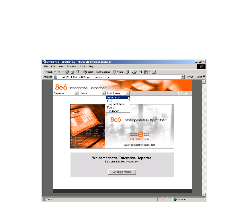
8E6 TECHNOLOGIES, ENTERPRISE REPORTER 3.0 USER’S GUIDE 57
ADMINISTRATOR SECTION: CHAPTER 2 - CONFIGURING THE ER 3.0 SERVER
Database Menu
The Database pull-down menu includes options for configur-
ing the database. These options are: IP.ID, Elapsed Time,
Tools, and Expiration.
User Name Identification screen
The User Name Identification screen displays when the IP.ID
option is selected from the Database menu. This screen is
used for configuring the Server to identify users based on the
IP addresses of their machines, their usernames, and/or their
machine names. Information set up on this screen is used by
the Client when logging a user’s Internet activity.
Fig. 1:2-20 Database menu, main screen
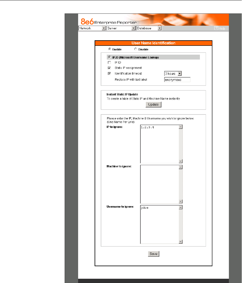
58 8E6 TECHNOLOGIES, ENTERPRISE REPORTER 3.0 USER’S GUIDE
ADMINISTRATOR SECTION: CHAPTER 2 - CONFIGURING THE ER 3.0 SERVER
Fig. 1:2-21 User Name Indentification screen with IP.ID activated
8E6 TECHNOLOGIES, ENTERPRISE REPORTER 3.0 USER’S GUIDE 59
ADMINISTRATOR SECTION: CHAPTER 2 - CONFIGURING THE ER 3.0 SERVER
As the administrator of the Server, you have the option to
either enable or disable this feature for logging users’ activi-
ties by usernames, machine names, and/or IP addresses of
machines.
WARNINGS
The ER 3.0 will generate NetBIOS requests outside
the network if IP.ID is activated and if no segment settings
have been specified in the configuration of the Web access
logging device—causing it to log external traffic. To resolve
this issue, the Web access logging device should be
modified to log activity only within the network. If a firewall is
used, it should be set up to prevent logging NetBIOS
requests outside the network.
NOTE: Depending on the type of Web access logging
device you are using, there may not be a configuration
parameter for segment settings.
Be sure the time zone specified for the ER 3.0 is the
same for each Web access logging device the ER 3.0 uses.
Failure in executing this setup will cause inconsistencies
when users’ logging times are reported, especially if IP.ID is
activated. If multiple Web access logging devices are used,
be sure to identify the subnets assigned to each of these
devices, as users cannot be tracked solely by IP address.
If using IP.ID, note that user login times are established
for set periods of 15 minutes, and if more than one user logs
onto the same machine during that time period, the activity
on that machine will be identified with the first user who
logged onto that machine. For example, the first user logs
on a machine for three minutes and then logs off. The
second user logs on the same machine for 11 minutes and
then logs off. The first user logs back on that machine for 16
minutes. All 30 minutes are logged as the first user’s activity.

60 8E6 TECHNOLOGIES, ENTERPRISE REPORTER 3.0 USER’S GUIDE
ADMINISTRATOR SECTION: CHAPTER 2 - CONFIGURING THE ER 3.0 SERVER
View the User Name Identification screen
If user name identification has been enabled and configura-
tions have been made on this screen, the IP.ID frame will be
populated. The frame with addresses, machines, and
usernames to ignore also may be populated.
Configure the Server to Log User Activity
1. Click the radio button corresponding to Enable.
NOTE: The IP.ID (Microsoft Username Lookup) radio button
is selected, indicating that users will be identified on the network
via the Microsoft username lookup file.
2. Select one or more of the following options by clicking in the
designated checkbox(es):
•IP.ID - log a user’s activity by username (login ID)
•Static IP assignment - log a user’s activity by the IP
address of the machine used
•Identification timeout - specify the amount of time the
Server will expend in reconciling a username with the IP
address of the machine used
NOTE: More about the Static IP assignment and Identifica-
tion timeout options can be found in the sub-sections that follow.
3. In the IP/Machine/Username to ignore list boxes, enter
all IP addresses, machine names, and/or usernames the
Server should disregard when identifying users. Each entry
should be made in a separate row.
4. After making all necessary entries on this screen, click the
Save button.

8E6 TECHNOLOGIES, ENTERPRISE REPORTER 3.0 USER’S GUIDE 61
ADMINISTRATOR SECTION: CHAPTER 2 - CONFIGURING THE ER 3.0 SERVER
Static IP Assignment
1. Click in the Static IP assignment checkbox to select the
option for logging a user’s activity by the IP address of the
machine used. When this option is selected, the Update
button in the Instant Static IP Update frame is activated.
2. Click the Update button to automatically generate a table
of static IP addresses and machine names. After this table
is created, the message screen displays to confirm the
successful execution of this task.
3. Click the Back button to return to the User Name Identifica-
tion screen.
TIP: Save this selection before exiting this screen.
Identification Timeout
1. Click in the Identification timeout checkbox to select the
option for specifying the amount of time the Server will
expend in reconciling a username with the IP address of
the machine used.
2. Make a selection from the pull-down menu to specify the
timeout (3, 6, 9, or 12 hours).
3. An entry in the Replace IP with text label field is optional.
This field is used for entering text that will replace the IP
address of any machine that is not assigned to a specific
user. To use this option, enter up to 14 characters of text for
the label. After saving this entry, when a report is generated
via the Client, this text will replace any IP address that
cannot be identified by username or machine name.
TIP: Save your entries before exiting this screen.
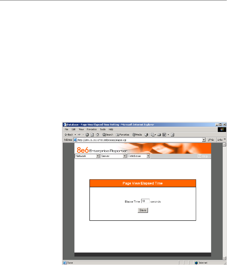
62 8E6 TECHNOLOGIES, ENTERPRISE REPORTER 3.0 USER’S GUIDE
ADMINISTRATOR SECTION: CHAPTER 2 - CONFIGURING THE ER 3.0 SERVER
Deactivate User Name Identification
1. Click the radio button corresponding to Disable.
2. Click the Save button.
Page View Elapsed Time screen
The Page View Elapsed Time screen displays when the
Elapsed Time option is selected from the Database menu.
This screen is used for establishing the value—amount of
time—that will be used when tracking the length of a user’s
stay at a given Web site, and the number of times the user
accesses that site.
Fig. 1:2-22 Page View Elapsed Time screen

8E6 TECHNOLOGIES, ENTERPRISE REPORTER 3.0 USER’S GUIDE 63
ADMINISTRATOR SECTION: CHAPTER 2 - CONFIGURING THE ER 3.0 SERVER
Establish the Unit of Elapsed Time for Page Views
1. In the Elapse Time field, enter the number of seconds that
will be used as the value when tracking a user’s visit to a
Web site.
2. Click the Save button.
Elapsed Time Rules
Each time a user on the network accesses a Web site, this
activity is logged as one or more visit(s) to that site. The
amount of time a user spends on that site and the number of
times he/she accesses that site is tracked according to the
following rules:
•A user will be logged as having visited a Web site one time
if the amount of time spent on any pages at that site is
equivalent to the value entered at the Elapse Time field, or
less than that value.
For example, if the value entered at the Elapse Time field is
10 seconds, and if the user is at a site between one to 10
seconds—on the same page or on any other page within
the same site—the user’s activity will be tracked as one
visit to that Web site.
•Each time the user exceeds the value entered at the Elapse
Time field, the user will be tracked as having visited the site
an additional time.
For example, if the value entered at the Elapse Time field is
10 seconds and the user remains at a Web site for 12
seconds, two visits to that site will be logged for him/her.
•Each session at a Web site is tracked as one or more
visit(s), depending on the duration of the session. A session
is defined as a user’s activity at a site that begins when the
user accesses the site and ends when the user exits the
site.
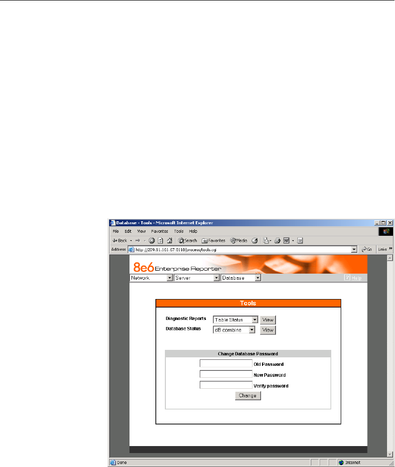
64 8E6 TECHNOLOGIES, ENTERPRISE REPORTER 3.0 USER’S GUIDE
ADMINISTRATOR SECTION: CHAPTER 2 - CONFIGURING THE ER 3.0 SERVER
For example, if the value entered at the Elapse Time field is
10 seconds and the user spends five seconds on a Web
site, then exits, then returns to the same site for another 15
seconds, the user will have two sessions or three visits to
that site logged for him/her (5 seconds = 1 visit, 15 seconds
= 2 visits, for a total of 3 visits).
Tools screen
The Tools screen displays when the Tools option is selected
from the Database menu. This screen is used for viewing
reports and logs to help you troubleshoot problems with the
Client application, and also is used for changing the database
password after the Client application has been configured.
Fig. 1:2-23 Tools screen

8E6 TECHNOLOGIES, ENTERPRISE REPORTER 3.0 USER’S GUIDE 65
ADMINISTRATOR SECTION: CHAPTER 2 - CONFIGURING THE ER 3.0 SERVER
The following options are available on this screen:
•View Diagnostic Reports
•View Database Status Logs
•Change Database (Client) Password
View Diagnostic Reports
1. Choose a report from the pull-down menu (Table Status,
Process List, Full Process List, Tables, or Daily Summary).
2. Click the View button to view the selected diagnostic report
in a popup window:
• Table Status - This report contains a list of Client table
names, and columns of statistics on each table, such as
type, size, number of rows, and time created and up-
dated.
• Process List - This report shows a list of current SQL
queries in the database, in an abbreviated format.
• Full Process List - This report shows a list of current
SQL queries in the database, in the full format that
includes all columns of data.
• Tables - This report contains a list of the names of tables
currently in the database.
•Daily Summary - This report shows the date range of
summary tables currently in the database.
3. Click the in the upper right corner of the popup window
to close the window.
View Database Status Logs
1. Choose a database status log from the pull-down menu (db
Combine, db Split, db Identify, Error Entries, or File Watch
Log).

66 8E6 TECHNOLOGIES, ENTERPRISE REPORTER 3.0 USER’S GUIDE
ADMINISTRATOR SECTION: CHAPTER 2 - CONFIGURING THE ER 3.0 SERVER
2. Click the View button to view the selected database status
log in a popup window:
• db Combine - This log shows the status of database
records combined from different machines.
• db Split - This log includes the status of records that are
moved from one table to another in the database.
• db Identify - This log shows the status of records that
populated tables in the database.
• Error Entries - This log displays a list of query errors.
• File Watch Log - This log shows a list of records that
were imported from one machine to another.
3. Click the in the upper right corner of the popup window
to close the window.
Change Database Password
NOTE: You can only change the database password if the
Client application has already been configured. (Refer to the
Client User Section, Chapter 1: Workstation Configuration, for
more information.) The default username is manager and the
default password is 8e6ReporT.
1. In the Old Password field, enter the password previously
set up for accessing the Client application. If this password
has never been changed, type in 8e6ReporT exactly as
shown here, using upper- and lowercase, alphanumeric
characters. For security purposes, an asterisk displays for
each character entered.
2. In the New Password field, enter a unique alphanumeric
password in upper- and/or lowercase characters. This
password is case sensitive. For security purposes, an
asterisk displays for each character entered.
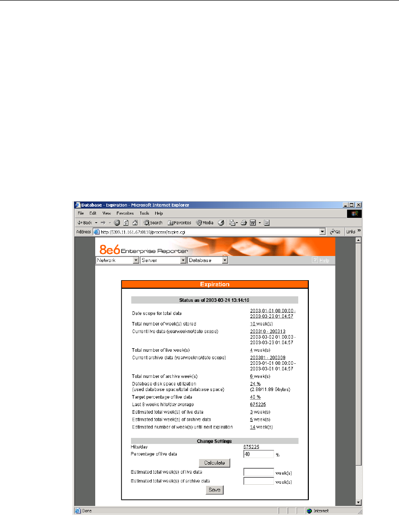
8E6 TECHNOLOGIES, ENTERPRISE REPORTER 3.0 USER’S GUIDE 67
ADMINISTRATOR SECTION: CHAPTER 2 - CONFIGURING THE ER 3.0 SERVER
3. In the Verify Password field, re-enter the password in the
exact format used in the New Password field. An asterisk
displays for each character entered at this field.
4. Click the Change button to display the screen confirming
that the password has been changed.
5. Click the Back button of the browser window to return to
the Tools screen.
Expiration screen
The Expiration screen displays when the Expiration option is
selected from the Database menu. This screen shows
Fig. 1:2-24 Expiration screen

68 8E6 TECHNOLOGIES, ENTERPRISE REPORTER 3.0 USER’S GUIDE
ADMINISTRATOR SECTION: CHAPTER 2 - CONFIGURING THE ER 3.0 SERVER
statistics on the amount of data currently stored on the Server
box, and provides an estimated date when that data will
expire. By reviewing the current database disk space utiliza-
tion and the average number of daily hits on your Server,
adjustments can be made to the number of weeks of live and
archive data you wish to store in the future before that data
expires.
NOTE: Though the database is backed up automatically
each day, under certain circumstances you may need to perform
a manual backup to the internal backup drive, and then save this
data off site. (See the Server Menu Backup screen section for
information on establishing backup procedures, and backing up
and restoring data on the ER 3.0 Server.)
Expiration Screen Terminology
The following terminology is used on the Expiration screen:
• Live - pertains to indexed data on the hard drive of the
Server for the most recent weeks—the period designated
as “live.” Indexed data includes pages and objects that
were accessed by users on the Internet, as well as the
indexes for these items.
When setting up the Server to store data, 8e6 recommends
that you allocate the highest percentage possible for live
data storage, since reports run faster if indexes are avail-
able for pages and objects.
If your Server is set up to store live data only (100 percent
live data), you will be able to store less data than if you store
both live and archive data, since indexes require additional
storage space.
• Archive - pertains to non-indexed data on the hard drive of
the Server for the oldest weeks—the period designated as
“archive.” Non-indexed data might include pages and/or
objects that were accessed by users on the Internet.

8E6 TECHNOLOGIES, ENTERPRISE REPORTER 3.0 USER’S GUIDE 69
ADMINISTRATOR SECTION: CHAPTER 2 - CONFIGURING THE ER 3.0 SERVER
Since archive data contain no indexes, they occupy less
space on the Server than live data—which include indexes
and pages/objects. However, reports generated for periods
of time with archive data take longer to process since
indexes are not included for that data.
• Expire - pertains to the action of dropping data from the
Server when there is no room left on the hard drive for
additional storage. When the hard drive reaches its maxi-
mum data storage capacity, indexes from the oldest week
of data stored on the Server are dropped, or “expired” from
the Server. Thereafter, when more space is needed on the
Server, the oldest week of non-indexed data “expires.”
Expiration Rules
The administrator of the Server specifies the number of
weeks of data that will be stored on the Server, based on the
storage capacity of the hard drive, and the number of hits on
the Server. After inputting the percentage of live data to be
stored, the Server translates that figure into the equivalent of
weekly time periods for live and/or archive data storage.
When the Server reaches the maximum number of weeks
allocated for live data storage, the oldest week of live data
stored on the Server attains an archive data status. In attain-
ing an archive data status, the index for that week of data is
dropped from the database tables.
When the Server reaches its maximum number of weeks
allocated for archive data storage, the oldest week of non-
indexed data stored on the Server is automatically dropped
(expired) from the database.
Once data expires, it cannot be recovered.

70 8E6 TECHNOLOGIES, ENTERPRISE REPORTER 3.0 USER’S GUIDE
ADMINISTRATOR SECTION: CHAPTER 2 - CONFIGURING THE ER 3.0 SERVER
View Data Storage Statistics
In the Status section of this screen, the date and time of the
last database expiration displays in the Status bar. The date
displays in the YYYY-MM-DD format, and the time displays in
military time (01-24 hours) using the HH:MM:SS time format.
The following data that displays is current as of the most
recent database expiration run:
• Data scope for total data - the date and time range of all
live and archive data currently stored on the Server. The
date displays in the YYYY-MM-DD format, and the time
displays in military time (01-24 hours) using the HH:MM:SS
time format.
• Total number of week(s) stored - the number of weeks
represented in the total data date scope.
• Current live data (yearweekno/date scope) - the range
of dates and times of live data currently stored on the
Server.
The first line displays the range of year(s) and weeks in the
YYYYWW format, where “Y” represents the year, and “W”
represents the week number in that year (01-52).
The second line displays the first date and time in the range
of live data currently stored on the Server. The date dis-
plays in the YYYY-MM-DD format, and the time displays in
military time (1-24 hours) using the HH:MM:SS time
format.
The third line displays the last date and time in the range of
live data currently stored on the Server, using the same
format as in the second line of data.
• Total number of live week(s) - the number of weeks
represented in the live data date scope.

8E6 TECHNOLOGIES, ENTERPRISE REPORTER 3.0 USER’S GUIDE 71
ADMINISTRATOR SECTION: CHAPTER 2 - CONFIGURING THE ER 3.0 SERVER
• Current archive data (yearweekno/date scope) - the
range of dates and times of archive data currently stored
on the Server.
The first line displays the range of year(s) and weeks in the
YYYYWW format, where “Y” represents the year, and “W”
represents the week number in that year (01-52).
The second line displays the first date and time in the range
of archive data currently stored on the Server. The date
displays in the YYYY-MM-DD format, and the time displays
in military time (1-24 hours) using the HH:MM:SS time
format.
The third line displays the last date and time in the range of
archive data currently stored on the Server, using the same
format as in the second line of data.
• Total number of archive week(s) - the number of weeks
represented in the archive data date scope.
• Database disk space utilization - the percentage of
space currently being used on the hard drive for both live
and archive data. If a high percentage displays, you may
want to expire data in the near term (see Change Data
Storage Settings).
• (used database space/total database space) - the
amount of space in Gigabytes currently being used on the
hard drive for both live and archive data, and the total
amount of space in Gigabytes (Gbytes) on the hard drive
allocated to database storage.
• Target percentage of live data - the percentage of live
data to be stored on the Server. If this figure is 100, only live
data will be stored. If this figure is less than 100, the re-
maining percentage to be stored will be archive data.
The percentage that displays can be changed by entering
and saving a different figure in the Percentage of live data
field in the Change Settings section of this screen.

72 8E6 TECHNOLOGIES, ENTERPRISE REPORTER 3.0 USER’S GUIDE
ADMINISTRATOR SECTION: CHAPTER 2 - CONFIGURING THE ER 3.0 SERVER
• Last 8 weeks hits/day average - the average number of
hits on the Server per day, based on the last eight weeks of
data stored on the Server.
The following data that displays is current as of the last
changes made in the Change Settings section of the screen:
• Estimated total week(s) of live data - the number of
weeks of live data the Server will store, based on your
specifications. This number is affected by the hits/day on
the Server, and the maximum number of weeks of data the
Server is able to hold.
The number of weeks of live data to be stored can be
changed by making a new entry in the Percentage of live
data field in the Change Settings section of this screen, and
saving the result of your calculations that displays below in
the Estimated total week(s) of live data field.
• Estimated total week(s) of archive data - the number of
weeks of archive data the Server will store, based on your
specifications. This number is affected by the hits/day on
the Server, and the maximum number of weeks of data the
Server is able to hold.
The number of weeks of archive data to be stored can be
changed by making a new entry in the Percentage of live
data field in the Change Settings section of this screen, and
saving the result of your calculations that displays below in
the Estimated total week(s) of archive data field.
• Estimated number of week(s) until next expiration - the
number of weeks from this week that data on the Server will
expire.

8E6 TECHNOLOGIES, ENTERPRISE REPORTER 3.0 USER’S GUIDE 73
ADMINISTRATOR SECTION: CHAPTER 2 - CONFIGURING THE ER 3.0 SERVER
Change Data Storage Settings
The Change Settings section of the screen is used for updat-
ing the amount of data that will be stored on the Server box in
the future. By making an entry in this section of the screen,
you dictate how data on the box will expire.
At the Hits/day field, the number of hits on the Server per day
displays. This is the same figure that displays in the Last 8
weeks hits/day average field in the Status section above.
1. In the Percentage of live data field, enter a figure for the
percentage of data you wish to be stored as live data on the
box. If you want all data to be live data only, enter 100.
2. Click the Calculate button to display results in the following
fields below: Estimated total week(s) of live data, and
Estimated total week(s) of archive data.
After viewing your results in these display fields, you can
adjust the number of weeks that data will be saved on the
Server, if necessary. To do so, follow steps 1 and 2 again.
3. Once you are satisfied with your results, click the Save
button. As a result of your entries, the following occurs:
•the figure saved in the Percentage of live data field
displays in the Target percentage of live data field in the
Status section
•the figures displayed in the Estimated total week(s) of
live/archive data fields display in the Estimated total
week(s) of live/archive data fields in the Status section
•the Estimated number of week(s) until next expiration
field may display a new figure, based on the new settings
you saved.
When the next database expiration runs, all other
fields in the Status section will reflect the new calcula-
tions.

74 8E6 TECHNOLOGIES, ENTERPRISE REPORTER 3.0 USER’S GUIDE
ADMINISTRATOR SECTION: CHAPTER 2 - CONFIGURING THE ER 3.0 SERVER
TIP: 8e6 recommends that you set up your Server to store
more live data than archive data for the benefit of administrators
and managers who generate reports via the Client application.
Report processing times are slower when generating reports that
include non-indexed data.
If your Server is set up to store only live data, you will be able to
store less data than if you store both live and archive data, since
indexes require additional storage space.

8E6 TECHNOLOGIES, ENTERPRISE REPORTER 3.0 USER’S GUIDE 75
CLIENT USER SECTION: INTRODUCTION
CLIENT USER SECTION
Introduction
This section of the User’s Guide provides instructions to
administrators on how to install software on workstations to
run the Client application, and information to managers on
how to utilize this application to generate report views and
interpret results.
Before installing the ER 3.0 Client application, the ER 3.0
Server must be fully configured, and the Structured Query
Language (SQL) server must be installed on the network and
connected to the Web access logging device(s).
After verifying that the necessary components are installed,
configured, and functioning, the administrator can begin
configuring the workstation(s) that will run the Client applica-
tion.

76 8E6 TECHNOLOGIES, ENTERPRISE REPORTER 3.0 USER’S GUIDE
CLIENT USER SECTION: CHAPTER 1 - WORKSTATION CONFIGURATION
Chapter 1: Workstation Configuration
Installation Components
In order to use the Client, the three components of this
application must be installed:
•Open Data Base Connectivity (ODBC) Driver - enables the
Client application to access data in the database via SQL
•Microsoft Access Runtime - engine used for sorting,
searching, and filtering the database when processing a
query
•Client application - tool used for generating views from the
database
The ODBC driver and MS Access Runtime are distributed to
the administrator on a CD-ROM. After these components are
installed, the Client application should be downloaded from
8e6’s Web site and installed on the workstation.
NOTE: Before you begin,verify that the CD-ROM includes
folders named MS RUNTIME and ODBC DRIVER. When install-
ing these components, the ODBC Driver folder must be opened
first, followed by the MS Runtime folder.
TIP: If you wish to install a new release of the Client to replace
a prior version of this application on your workstation, refer to the
following instructions under the Download and Install the Client
sub-section in this chapter:
•Download the Client
•Uninstall the Client, Install New Release
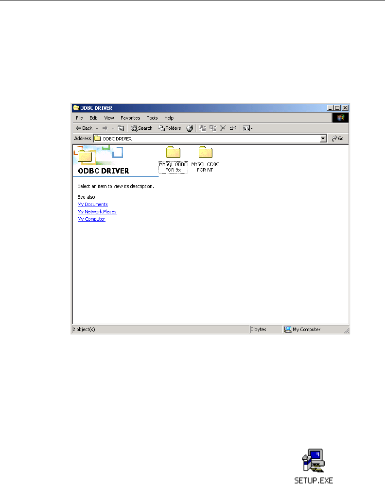
8E6 TECHNOLOGIES, ENTERPRISE REPORTER 3.0 USER’S GUIDE 77
CLIENT USER SECTION: CHAPTER 1 - WORKSTATION CONFIGURATION
Fig. 2:1-1 ODBC folder
Install the ODBC Driver
1. Open the ODBC DRIVER folder to display folders contain-
ing ODBC drivers for Microsoft Windows 9x-based and NT-
based operating systems:
2. Click on the folder corresponding to your machine type:
• MYSQL ODBC FOR 9x - ODBC driver for Windows 98,
and ME.
• MYSQL ODBC FOR NT - ODBC driver for Windows
2000, NT 4.0, and XP.
3. With the folder of your choice opened, click
the SETUP.EXE icon to open the Microsoft
ODBC Setup window and dialog box:
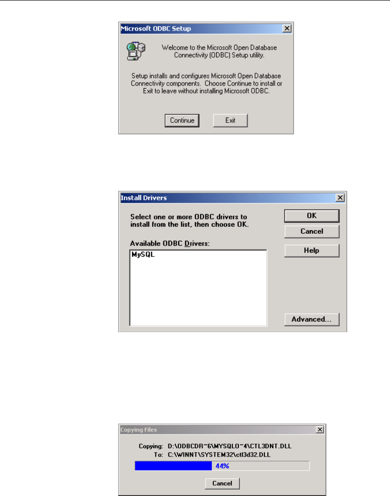
78 8E6 TECHNOLOGIES, ENTERPRISE REPORTER 3.0 USER’S GUIDE
CLIENT USER SECTION: CHAPTER 1 - WORKSTATION CONFIGURATION
4. Click Continue to open the Install Drivers dialog box:
5. From the list of Available ODBC Drivers, click on MySQL to
highlight this selection, then click OK to copy files from the
CD to your hard drive:
Fig. 2:1-2 Microsoft ODBC dialog box
Fig. 2:1-3 Install Drivers dialog box
Fig. 2:1-4 Copying Files dialog box
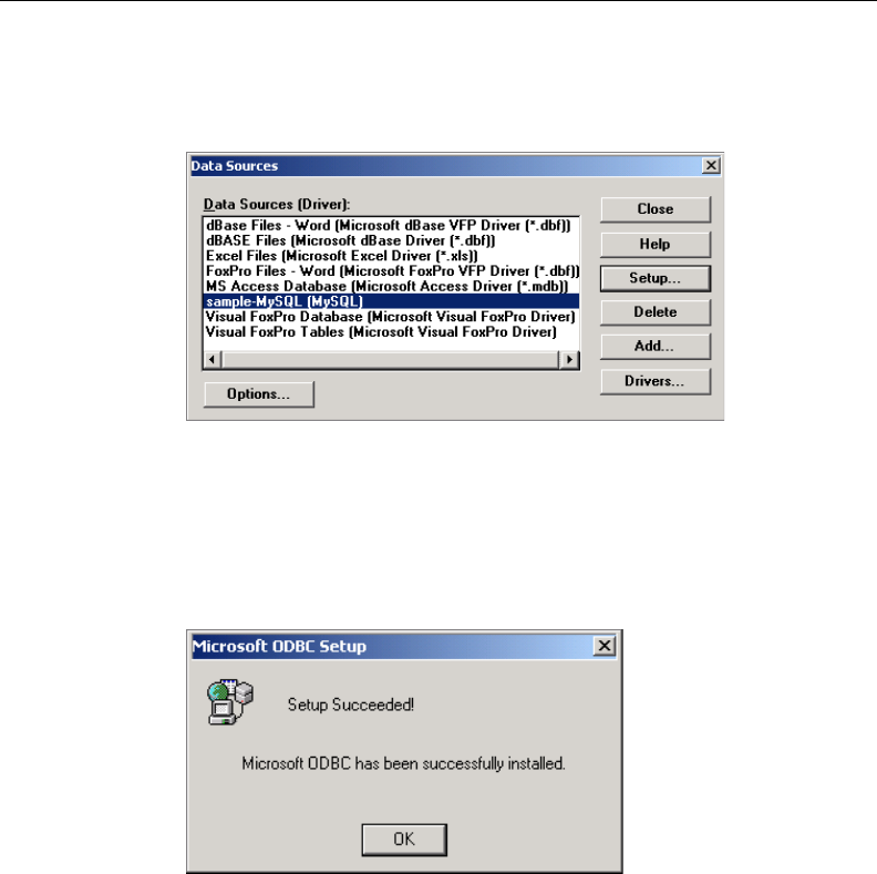
8E6 TECHNOLOGIES, ENTERPRISE REPORTER 3.0 USER’S GUIDE 79
CLIENT USER SECTION: CHAPTER 1 - WORKSTATION CONFIGURATION
Fig. 2:1-6 Microsoft ODBC alert box
After the files are copied to your machine, the Data Sources
dialog box opens, displaying a list of available drivers:
6. Click Close to display the Microsoft ODBC Setup alert box
with a message indicating the driver has been successfully
installed:
7. Click OK to close the alert box and to return to your desk-
top.
You can now install Microsoft Access Runtime.
Fig. 2:1-5 Data Sources dialog box
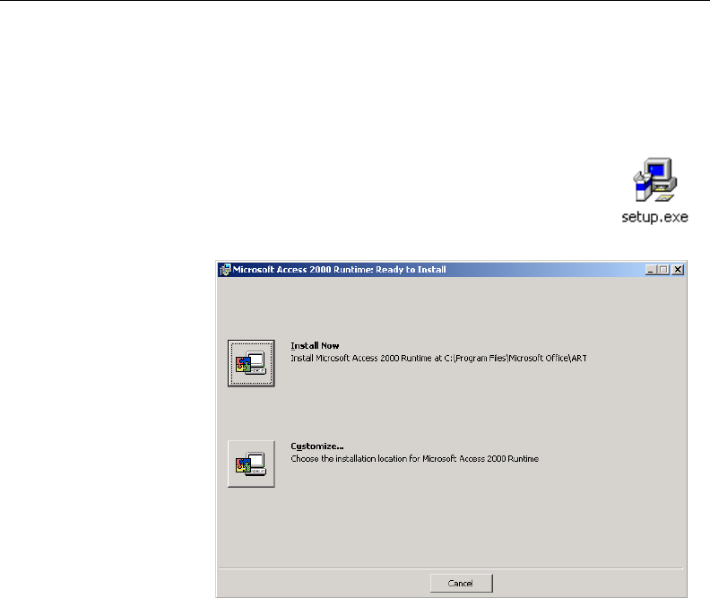
80 8E6 TECHNOLOGIES, ENTERPRISE REPORTER 3.0 USER’S GUIDE
CLIENT USER SECTION: CHAPTER 1 - WORKSTATION CONFIGURATION
Install Microsoft Access Runtime
With the ODBC driver installed, you are ready to install MS
Access Runtime.
1. Open the MS RUNTIME folder and click the
setup.exe icon to display the MS Access
Runtime - Ready to Install dialog box:
2. Click the button corresponding to Customize to open the
Installation Location dialog box:
Fig. 2:1-7 Microsoft Access Runtime dialog box
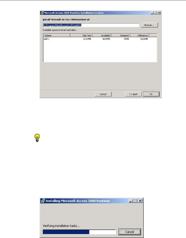
8E6 TECHNOLOGIES, ENTERPRISE REPORTER 3.0 USER’S GUIDE 81
CLIENT USER SECTION: CHAPTER 1 - WORKSTATION CONFIGURATION
3. At the Install Runtime field, specify the location where the
application will be installed. The default path is C:\Program
Files\Microsoft Office\ART\.
TIP: 8e6 recommends that you create a folder named 8e6
SQL on your local “C” drive and install Access Runtime in this
folder.
4. After specifying the installation path, click OK to reopen the
Access Runtime - Ready to Install dialog box (see Fig.
2:1-7).
5. Click the button corresponding to Install Now to begin
installing the application:
Fig. 2:1-8 Installation Location dialog box
Fig. 2:1-9 Installing Access Runtime dialog box

82 8E6 TECHNOLOGIES, ENTERPRISE REPORTER 3.0 USER’S GUIDE
CLIENT USER SECTION: CHAPTER 1 - WORKSTATION CONFIGURATION
An alert box pops up with message to inform you when the
installation is complete.
6. Click OK to close the alert box and to return to your desk-
top.
You can now download and install the Client application.
Download and Install the Client
After the ODBC driver and MS Access Runtime are installed,
the Client application should be downloaded from 8e6’s Web
site and installed on your machine.
This sub-section includes instructions for downloading and
installing the Client application for the first time, and for
installing a new release to replace an existing version of the
Client on your machine.
Download the Client
1. Go to http://www.8e6technologies.com/tools/er.html to
access the Web page “Enterprise Reporter (ER) Tools:
Upgrades/Tools.”
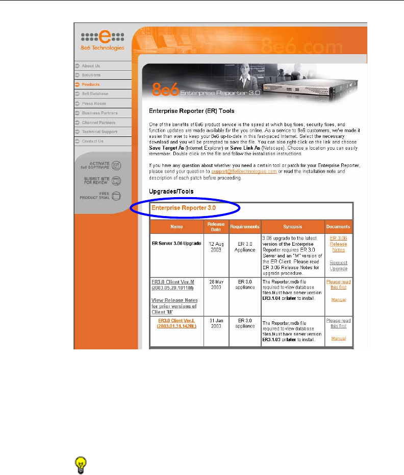
8E6 TECHNOLOGIES, ENTERPRISE REPORTER 3.0 USER’S GUIDE 83
CLIENT USER SECTION: CHAPTER 1 - WORKSTATION CONFIGURATION
2. In the Enterprise Reporter 3.0 section of the page, click on
the link for the latest Reporter.exe file.
3. In the Save As popup window, save the file to your ma-
chine, then close the popup window and the Web page.
TIP: 8e6 recommends saving the “.exe” file on the desktop of
your workstation. This self-extracting Zip file will open when you
click on it.
Fig. 2:1-10 Upgrades/Tools page, Enterprise Reporter 3.0 circled
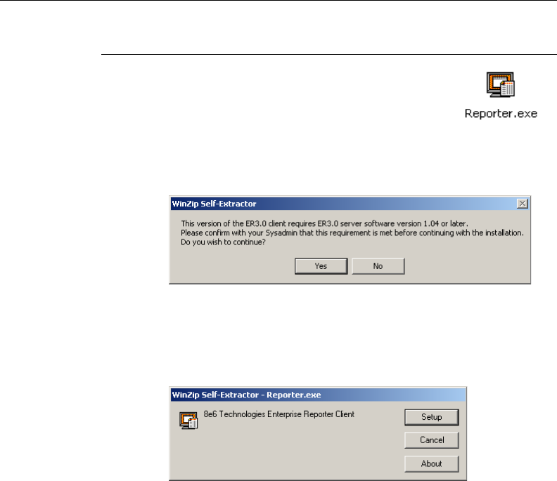
84 8E6 TECHNOLOGIES, ENTERPRISE REPORTER 3.0 USER’S GUIDE
CLIENT USER SECTION: CHAPTER 1 - WORKSTATION CONFIGURATION
Install the Client
1. If you saved the Reporter.exe file to your
desktop, click on the Reporter.exe icon:
This action opens the dialog box warning
you that the Client application will only work if connected to
an ER 3.0 Server:
2. Click Yes to open the dialog box for the self-extracting Zip
file:
3. Click the Setup button to extract the contents of the file to
your machine.
After the contents of the file are extracted, the installation
Wizard installs itself on your machine, then takes you
through the steps of the installation process:
Fig. 2:1-12 Reporter.exe self-extracting Zip file
Fig. 2:1-11 Warning dialog box
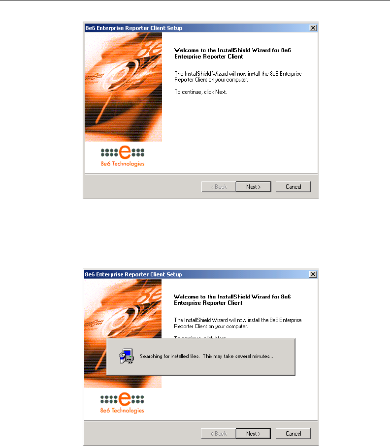
8E6 TECHNOLOGIES, ENTERPRISE REPORTER 3.0 USER’S GUIDE 85
CLIENT USER SECTION: CHAPTER 1 - WORKSTATION CONFIGURATION
4. Click the Next button to tell the Wizard to search your
machine for pertinent files that were installed:
Fig. 2:1-14 Searching for files
Fig. 2:1-13 Installation Wizard
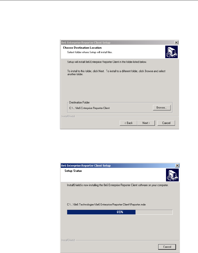
86 8E6 TECHNOLOGIES, ENTERPRISE REPORTER 3.0 USER’S GUIDE
CLIENT USER SECTION: CHAPTER 1 - WORKSTATION CONFIGURATION
5. Once all pertinent files have been located, click Next to
select the folder in which the Client application will be
installed:
6. Click Next to install the Client application on your machine:
Fig. 2:1-15 Specify folder for Client installation
Fig. 2:1-16 Installing the Client application
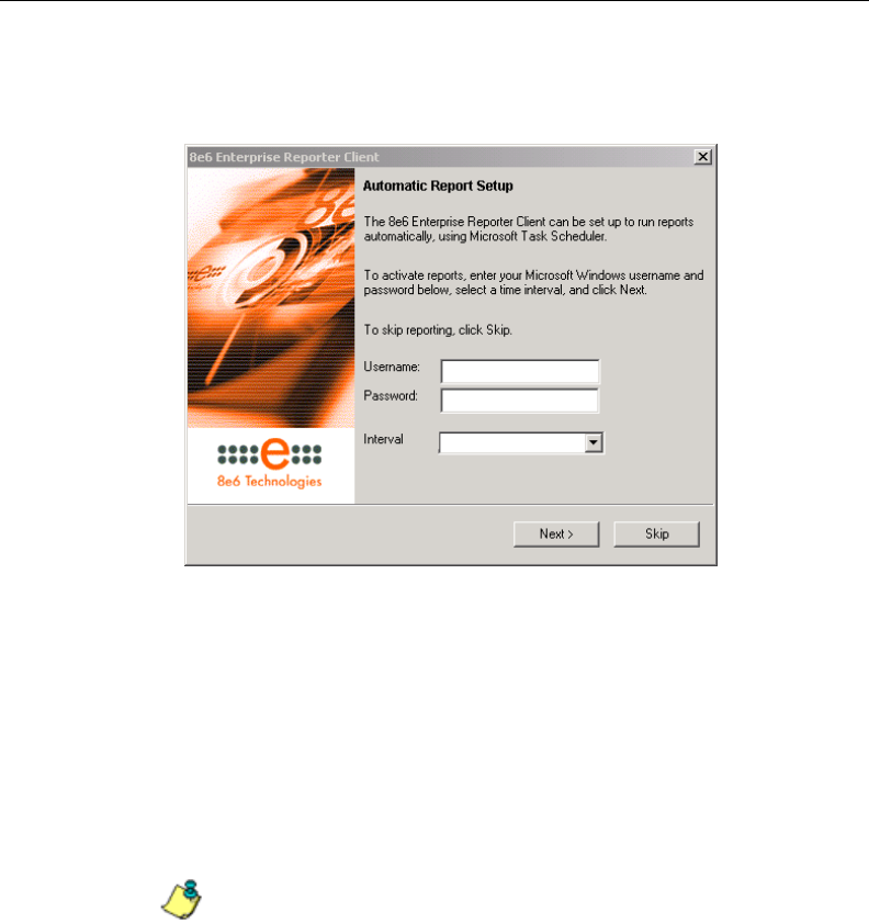
8E6 TECHNOLOGIES, ENTERPRISE REPORTER 3.0 USER’S GUIDE 87
CLIENT USER SECTION: CHAPTER 1 - WORKSTATION CONFIGURATION
After the Client has been installed, the automatic reporting
option becomes available to you:
7. You must either set up automatic reporting or bypass this
option. By choosing automatic reports, the Microsoft Task
Scheduler will generate reports at the time interval speci-
fied via this Wizard.
If you choose to bypass the option for setting up automatic
reporting, you can later set up reports to run automatically
via Microsoft’s Scheduled Task Wizard.
NOTE: For information on setting up the task scheduler, see
Event Schedule in Chapter 3: Customizing the Client, and
Appendix A: Scheduled Task Wizard.
Fig. 2:1-17 Automatic Report Setup
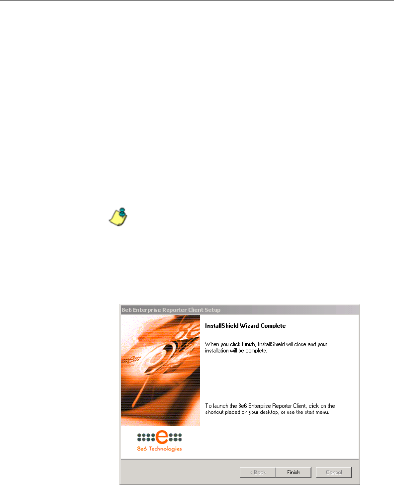
88 8E6 TECHNOLOGIES, ENTERPRISE REPORTER 3.0 USER’S GUIDE
CLIENT USER SECTION: CHAPTER 1 - WORKSTATION CONFIGURATION
•To set up automatic reporting, specify the following
criteria:
a. Username - enter the alphanumeric, case sensitive
username of the user at this workstation.
b. Password - enter the alphanumeric, case sensitive
password of the user.
c. Interval - specify the interval of time when reports will
be generated (every 15 or 30 minutes; every hour; or
every 2, 4, 12, or 24 hours).
d. Click the Next button.
•To bypass this option, click the Skip button.
NOTE: 8e6 recommends that you select the automatic report
option and set up reports to run each hour.
After clicking either the Next or Skip button in the Automatic
Report Setup window, the Wizard indicates that the instal-
lation is complete:
Fig. 2:1-18 Installation complete
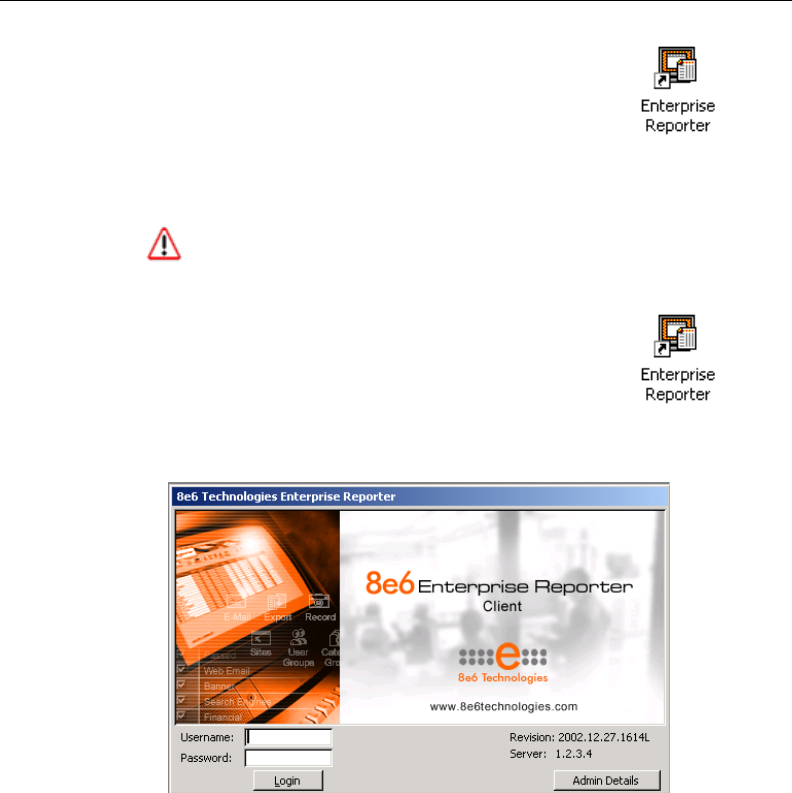
8E6 TECHNOLOGIES, ENTERPRISE REPORTER 3.0 USER’S GUIDE 89
CLIENT USER SECTION: CHAPTER 1 - WORKSTATION CONFIGURATION
Fig. 2:1-19 Login window with unchanged Server address
8. Click the Finish button to close the Wizard and
to return to your desktop where you will find a
shortcut to the Client application
(reporter.mde file):
Update the Server Address and Password
WARNING: Before you can use the Client, you must change
the entry for the Server address and database password.
1. Launch the Client application by clicking on the
Enterprise Reporter icon (reporter.mde file)
located on your desktop or in the folder where
the icon was saved:
The login window displays when you access the Client:
2. Click the Admin Details button to open the Admin: Form
popup box:
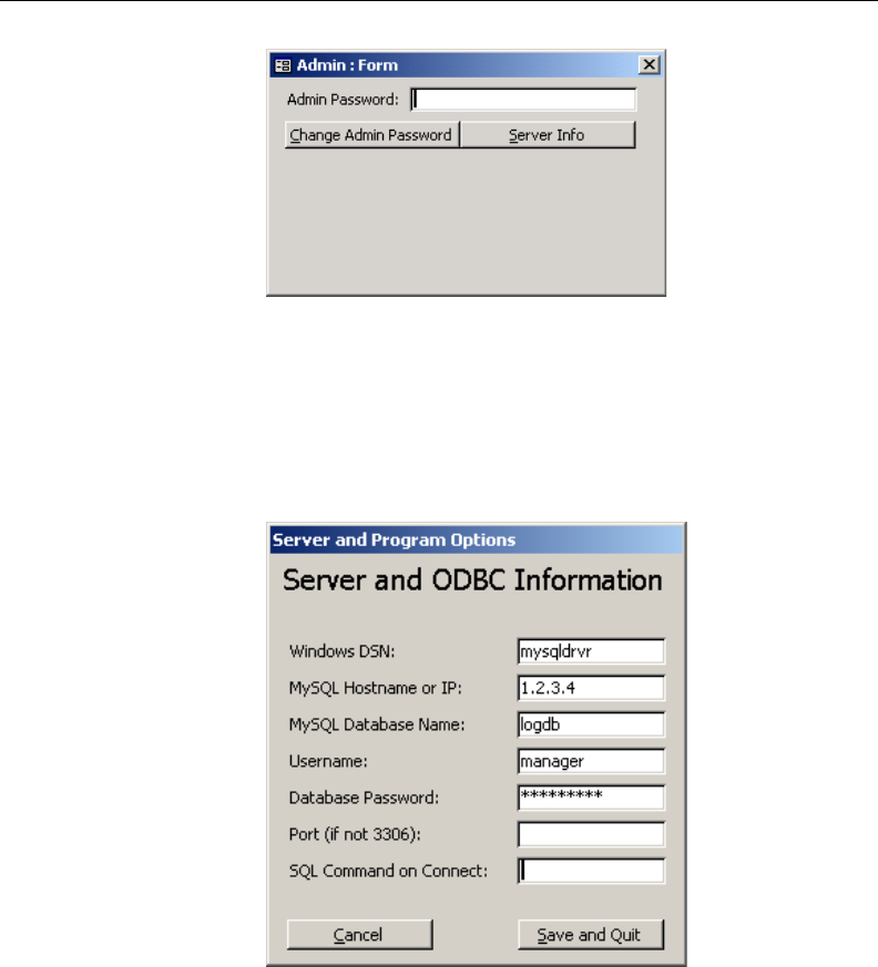
90 8E6 TECHNOLOGIES, ENTERPRISE REPORTER 3.0 USER’S GUIDE
CLIENT USER SECTION: CHAPTER 1 - WORKSTATION CONFIGURATION
3. In the Admin Password field, type in the default password
admin exactly as shown here, in lowercase letters.
4. Click the Server Info button to display the Server and
ODBC Information box:
5. In the MySQL Hostname or IP field, change the entry from
“1.2.3.4” to the IP address of your ER 3.0 Server, entered in
the LAN 1 IP field on the Network Settings screen of the
Administrator GUI.
Fig. 2:1-20 Admin: Form popup box
Fig. 2:1-21 Unchanged IP address and password

8E6 TECHNOLOGIES, ENTERPRISE REPORTER 3.0 USER’S GUIDE 91
CLIENT USER SECTION: CHAPTER 1 - WORKSTATION CONFIGURATION
NOTE: If you don’t know the IP address, contact the adminis-
trator of your ER 3.0 Server. For more information about the IP
address, see the Network Settings screen sub-section under the
Network menu in the Administrator Section.
6. In the Database Password field, change the entry from
“8e6ReporT” to the password set up for the ER 3.0 Server,
if necessary.
WARNING: This password must be the same password
entered on the Tools screen in the Administrator GUI. (The
default password is 8e6ReporT.) If you don’t know the database
password, contact the administrator of your ER 3.0 Server. For
more information about the Database Password, see the Tools
screen sub-section under the Database menu in the Administra-
tor Section.
7. Click Save and Quit to accept your settings and to exit the
Client. When you launch the Client again, use the pass-
word you just set up.
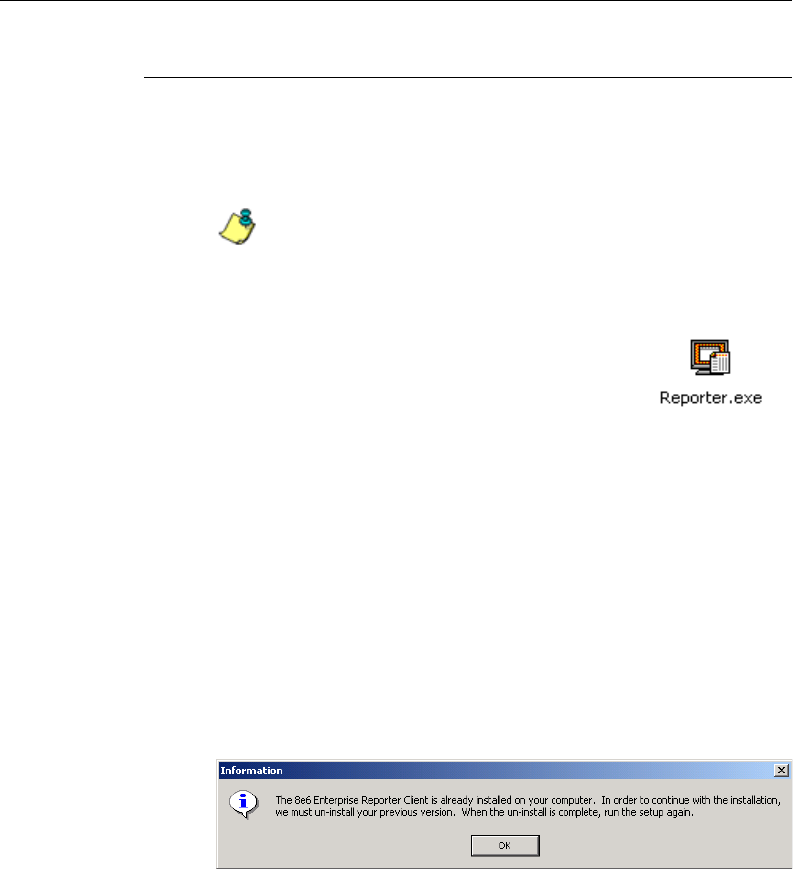
92 8E6 TECHNOLOGIES, ENTERPRISE REPORTER 3.0 USER’S GUIDE
CLIENT USER SECTION: CHAPTER 1 - WORKSTATION CONFIGURATION
Uninstall the Client, Install New Release
Follow these steps if you have the Client application installed
on your workstation and would like to replace that version
with a new release of the application.
NOTE: Before uninstalling the Client from your workstation,
be sure that the application is not currently open on your ma-
chine.
1. After downloading the new release of the
Reporter.exe file to your machine, if you
saved that file to your desktop, click the
Reporter.exe icon to open the warning
dialog box (see Fig. 2:1-11).
2. Click the Yes button to open the dialog box for the self-
extracting Zip file (see Fig. 2:1-12).
3. Click the Setup button to extract the contents of the file to
your machine. After the contents of the file are extracted,
the installation Wizard installs itself on your machine.
Since a previous version of the Client application is already
installed on your machine, the old version must be
uninstalled before you can install the new version, as
indicated by the message in the alert box:
Fig. 2:1-22 Information alert box
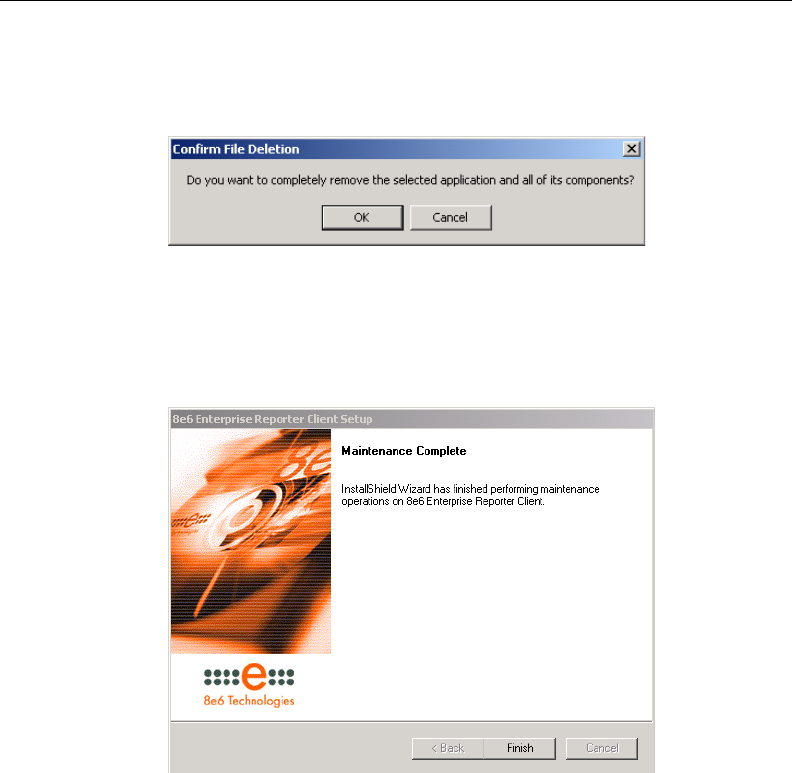
8E6 TECHNOLOGIES, ENTERPRISE REPORTER 3.0 USER’S GUIDE 93
CLIENT USER SECTION: CHAPTER 1 - WORKSTATION CONFIGURATION
4. Click OK to open the confirmation dialog box for
uninstalling the application:
5. Click OK to display the Maintenance Complete Wizard that
indicates the Client application has been uninstalled:
6. Click the Finish button to close the Wizard and to return to
your desktop.
7. Follow the procedures documented in Install the Client to
install the new version of the Client application. Be sure to
update the Server address and password.
Fig. 2:1-24 Maintenance Complete
Fig. 2:1-23 Confirmation dialog box
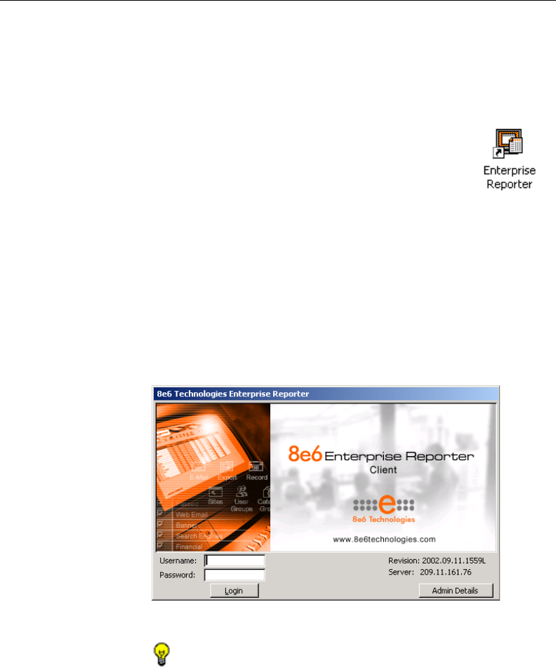
94 8E6 TECHNOLOGIES, ENTERPRISE REPORTER 3.0 USER’S GUIDE
CLIENT USER SECTION: CHAPTER 2 - ACCESSING THE CLIENT
Chapter 2: Accessing the Client
Launch the Client Application
Launch the Client application by clicking on the
Enterprise Reporter icon (reporter.mde file)
located on your desktop or in the folder where
the icon was saved:
Login window
The login window displays when you access the Client
application. This window serves as a portal for managers to
log into the Client, and gives the administrator access to
popup windows for changing passwords and modifying a set
of server components.
TIP: Administrators who access the Client application for the
first time should change the administrator password, as de-
scribed on the next pages. This ensures that only the administra-
tor will be able to modify server components.
Fig. 2:2-1 Client Login window
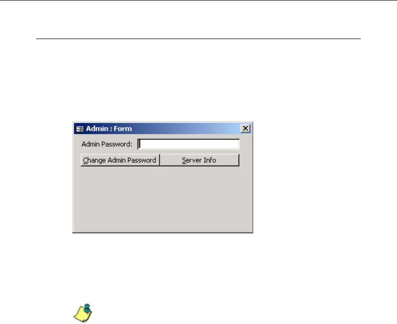
8E6 TECHNOLOGIES, ENTERPRISE REPORTER 3.0 USER’S GUIDE 95
CLIENT USER SECTION: CHAPTER 2 - ACCESSING THE CLIENT
Administrator Details
To change the password of the administrator, or to modify
server components—including the manager’s username and
password—click the Admin Details button to open the
Admin: Form popup box:
Change the Administrator Password
NOTE: The administrator password is different than the
manager password, the latter which is used at the Password field
in the login window.
1. In the Admin Password field, if this password has never
been changed, type in the default password admin exactly
as shown here, in lowercase letters. Otherwise, enter the
administrator password.
2. Click the Change Admin Password button to display the
Changing Admin Password dialog box:
Fig. 2:2-2 Admin: Form popup box
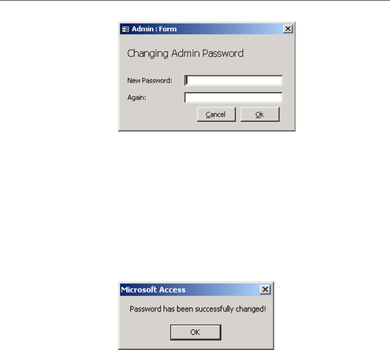
96 8E6 TECHNOLOGIES, ENTERPRISE REPORTER 3.0 USER’S GUIDE
CLIENT USER SECTION: CHAPTER 2 - ACCESSING THE CLIENT
3. In the New Password field, enter an alphanumeric pass-
word in upper- and/or lowercase characters.
4. In the Again field, re-enter the password in the exact format
used at the New Password field.
5. Click the OK button to accept your changes and to close
the popup box. As a result of this action, a confirmation
message displays:
6. Click OK to close the alert box and to return to your desk-
top.
View, Modify Server Information
In addition to changing the administrator password, the
Client’s administrator can modify a set of server components,
such as manager usernames and passwords for accessing
the Client application.
Fig. 2:2-3 Changing Admin Password box
Fig. 2:2-4 Password alert box
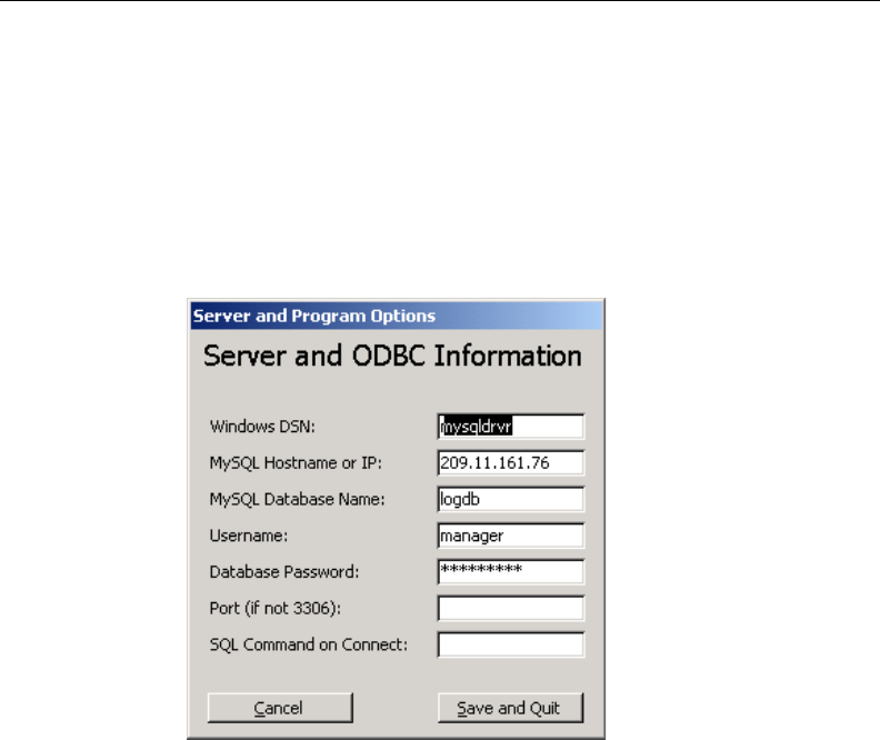
8E6 TECHNOLOGIES, ENTERPRISE REPORTER 3.0 USER’S GUIDE 97
CLIENT USER SECTION: CHAPTER 2 - ACCESSING THE CLIENT
1. In the Admin Password field of the Admin: Form popup
box (see Fig. 2:2-2), if the administrator password has
never been changed, type in the default password admin
exactly as shown here, in lowercase letters. Otherwise,
enter the administrator password.
2. Click the Server Info button to display the Server and
ODBC Information box:
3. The following fields can be viewed and edited, if necessary:
• Windows DSN - case sensitive Data Source Name of
the OBDC driver (default is mysqldrvr)
• MySQL Hostname or IP - IP address of the ER 3.0
Server
• MySQL Database Name - case sensitive database
name (default is logdb)
• Username - case sensitive, alphanumeric manager
username to be used at the Username field in the Client
login window (default is manager)
Fig. 2:2-5 Server and ODBC Information box
98 8E6 TECHNOLOGIES, ENTERPRISE REPORTER 3.0 USER’S GUIDE
CLIENT USER SECTION: CHAPTER 2 - ACCESSING THE CLIENT
• Database Password - case sensitive, alphanumeric
manager password to be used at the Password field in
the Client login window (default is 8e6ReporT).
WARNING: This password must be the same password
entered on the Tools screen in the Administrator GUI.
• Port (if not 3306) - port number (default is blank or zero)
• SQL Command on Connect - SQL command when
connection is made (default is blank)
4. The next step differs depending on whether entries were
made in the Server and ODBC Information box:
•If edits were made in this box, click the Save and Quit
button to exit the Client and to return to your desktop. To
re-access the Client, you will need to launch this applica-
tion again.
•To exit this box without making modifications, click the
Cancel button to close this box and to return to the login
window.
NOTE: The only components you might change after
installation are the username and password, and the IP address
of the Server. Contact 8e6 Technologies customer service
before changing the IP address from the one assigned the
Client during installation.
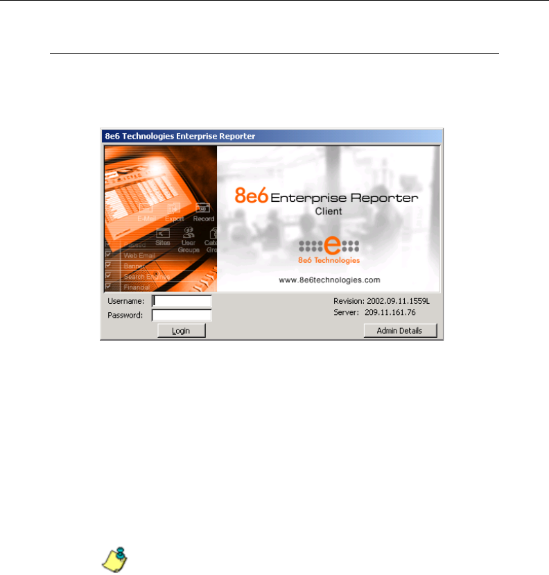
8E6 TECHNOLOGIES, ENTERPRISE REPORTER 3.0 USER’S GUIDE 99
CLIENT USER SECTION: CHAPTER 2 - ACCESSING THE CLIENT
Log In
In order to log in the Client, you must enter the manager
username and password in the login window:
1. In the Username field, type in your username. If you have
not had your username changed, enter the default
username manager in lowercase letters, as shown here.
2. In the Password field, type in your password. If you have
not had your password changed, enter the default pass-
word 8e6ReporT, using upper- and lowercase letters, as
shown here. A series of asterisks displays for each charac-
ter entered.
NOTE: Manager usernames and passwords can be modified
in the Admin: Form popup box of the Client, accessible via the
Admin Details button.
3. Click the Login button to display the ER Server Information
popup box:
Fig. 2:2-6 Client Login window
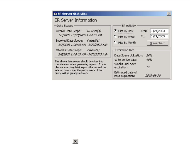
100 8E6 TECHNOLOGIES, ENTERPRISE REPORTER 3.0 USER’S GUIDE
CLIENT USER SECTION: CHAPTER 2 - ACCESSING THE CLIENT
Fig. 2:2-7 ER Server Information popup box
Server Statistics
The ER Server Information popup box contains details about
data storage on the ER 3.0 Server. This popup box is com-
prised of three frames: Date Scopes, ER Activity, and Expira-
tion Info.
Click the in the upper right corner of the ER Server Infor-
mation popup box to close it.
Date Scopes
In the Date Scopes frame, the number of week(s) of data
stored on the ER 3.0 Server, and the date and time range
display for the following date scopes:
• Overall Date Scope - this date scope pertains to all data
currently stored on the Server, including both live (indexed)
and archive (non-indexed) data.
• Indexed Date Scope - this date scope pertains only to live
data currently stored on the Server. Live data can include
Web pages and objects, and will always include the in-
dexes for these items. Objects include images from Web
pages, and items such as JavaScript files and flash files.

8E6 TECHNOLOGIES, ENTERPRISE REPORTER 3.0 USER’S GUIDE 101
CLIENT USER SECTION: CHAPTER 2 - ACCESSING THE CLIENT
• Objects Date Scope - this date scope pertains only to
objects currently stored on the Server. If this date scope
overlaps the date ranges for indexed and non-indexed data
currently stored on the Server, both live and archive items
will be included in this date scope.
Expiration Info
In the Expiration Info frame, the following data displays:
• Data Space Utilization - the percentage of database
storage space currently being used on the ER 3.0 Server
• % to be live data - the percentage of data that is set to be
live data stored on the Server
• Weeks until next expiration - the number of weeks from
this week that data on the Server will expire
• Estimated date of next expiration - the date scheduled
for the next automatic database expiration
ER Activity
In the ER Activity frame, you specify the type of chart you
wish to generate that will show details on the number of hits
on the Server within a specified time period.
In the From and To fields, today’s date displays.
1. Click in the From date box, and enter the first date in the
date range, in the M/D/YYYY or MM/DD/YYYY format.
2. Click in the To date box, and enter the last date in the date
range, in the M/D/YYYY or MM/DD/YYYY format.
3. Click the radio button corresponding to Hits By Day, Hits
By Week, or Hits By Month.
4. Click the Draw Chart button to open a window that displays
the chart of your selection.
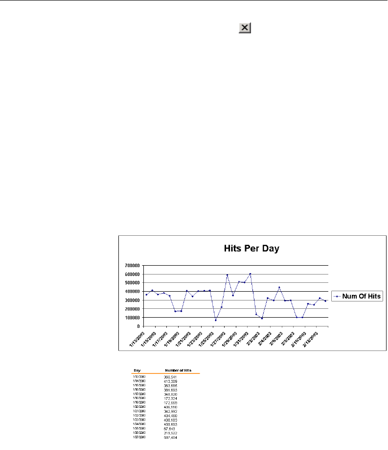
102 8E6 TECHNOLOGIES, ENTERPRISE REPORTER 3.0 USER’S GUIDE
CLIENT USER SECTION: CHAPTER 2 - ACCESSING THE CLIENT
5. To view the chart, click the in the upper right corner of
the ER Server Information popup box to close it.
The top portion of the chart includes the title of the chart,
and a graph showing the number of hits for the specified
time period.
The bottom portion of the chart includes the time measure-
ment (day, week, or month) and the Number of Hits corre-
sponding to each time measurement.
Depending on the time frame specified, this chart may be
several pages in length.
• Hits By Day - If you selected Hits By Day, each day within
the date range is plotted on the graph, with the date
(month, day, and year) labeled below.
Fig. 2:2-8 Hits Per Day chart
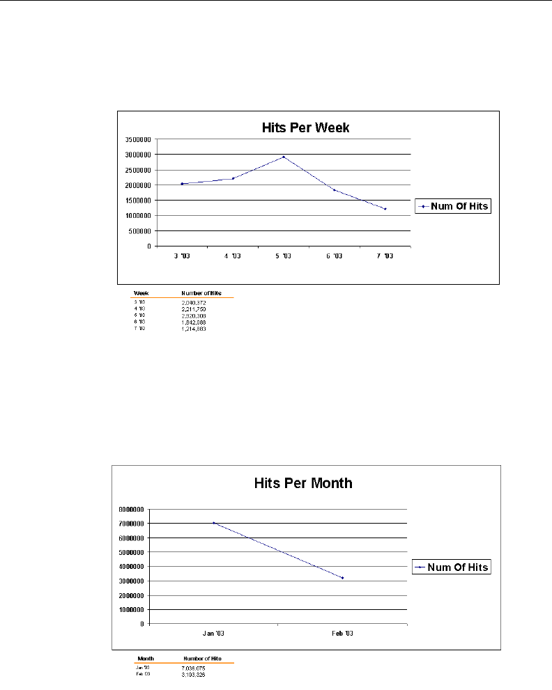
8E6 TECHNOLOGIES, ENTERPRISE REPORTER 3.0 USER’S GUIDE 103
CLIENT USER SECTION: CHAPTER 2 - ACCESSING THE CLIENT
• Hits Per Week - If you selected Hits Per Week, each
week within the date range is plotted on the graph, with
the number of the week (1-52) and year labeled below.
• Hits Per Month - If you selected Hits Per Month, each
month within the date range is plotted on the graph, with
the month and year labeled below.
Fig. 2:2-9 Hits Per Week chart
Fig. 2:2-10 Hits Per Month chart

104 8E6 TECHNOLOGIES, ENTERPRISE REPORTER 3.0 USER’S GUIDE
CLIENT USER SECTION: CHAPTER 2 - ACCESSING THE CLIENT
You now have the option to print the chart, close the chart
window, or generate a new chart.
To print the chart, click File > Print.
To close the chart window, click the in the upper right
corner of the window.
To generate a new chart:
1. Click the in the upper right corner of the chart window to
close it, and to display the main menu:
2. Click the Settings button to open the Settings box that
displays a menu of options for customizing the Client
application:
Fig. 2:2-11 Client application main menu
8E6 TECHNOLOGIES, ENTERPRISE REPORTER 3.0 USER’S GUIDE 105
CLIENT USER SECTION: CHAPTER 2 - ACCESSING THE CLIENT
NOTE: If you are not the administrator, you will only see
options for Event Schedule, My Account, Server Statistics, and
Default Options. More about these buttons and icons—and the
functions of their corresponding windows and screens—can be
found in subsequent chapters in this Client User Section of the
User’s Guide.
3. Click the Server Statistics button to re-open the ER
Server Information popup box.
4. Follow the steps in this sub-section for generating a chart.
Navigate the Main Menu
The main menu (see Fig. 2:2-11) is comprised of buttons and
icons, and also displays the Server IP address and Client
application Revision code.
NOTE: More about these buttons and icons—and the
functions of their corresponding windows and screens—can be
found in subsequent chapters in this Client User Section of the
User’s Guide.
Fig. 2:2-12 Settings box menu

106 8E6 TECHNOLOGIES, ENTERPRISE REPORTER 3.0 USER’S GUIDE
CLIENT USER SECTION: CHAPTER 2 - ACCESSING THE CLIENT
Buttons
The buttons on the main menu provide access to popup
windows with options for customizing the Client application or
for searching the database:
• Settings - click this button to access options for customiz-
ing the Client application.
• Specific Search - click this button to perform a search for
pages or objects either viewed at a site or by a single user.
Icons
Clicking an icon on the main menu provides access to
screens or boxes displaying reporting information for the
selected item:
• Categories - click this icon to view a report showing data in
each filter category that was set up for monitoring user
activity.
• IPs - click this icon to view a report showing Internet activity
by user IP address.
• Users - click this icon to view a report showing Internet
activity by username.
• Sites - click this icon to view a report showing activity on
Web sites users accessed.
• Category Groups - click this icon to view a report showing
activity by category groups, if category groups previously
have been established.
• User Groups - click this icon to view a report showing
activity by user groups, if user groups previously have been
established.
8E6 TECHNOLOGIES, ENTERPRISE REPORTER 3.0 USER’S GUIDE 107
CLIENT USER SECTION: CHAPTER 2 - ACCESSING THE CLIENT
• Record - click this icon to open a dialog box where custom-
ized settings for a previously recorded report view can be
viewed and modified, and the report can be run.
• Exit - click this icon to log out of the Client.
Details on each of these menu items are included in subse-
quent sub-sections.
Log Out
To log out of the Client application, click the Exit icon or
the in the upper right corner of the browser window.
108 8E6 TECHNOLOGIES, ENTERPRISE REPORTER 3.0 USER’S GUIDE
CLIENT USER SECTION: CHAPTER 3 - CUSTOMIZING THE CLIENT
Chapter 3: Customizing the Client
This chapter provides information on customizing the Client
to generate reports based on your specified settings.
Settings
From the main menu, click the Settings button to open the
Settings box that shows a menu of options for customizing
the Client:
If you are logged in as the administrator, the following options
are available to you: Event Schedule, Category Descriptions,
Category Groupings, User Groupings, User Permissions,
and Default Options. The Admin Details and Server Statistics
selections—documented in the Administrator Details sub-
section and Log In sub-section in Chapter 2—also are avail-
able.
Fig. 2:3-1 Settings menu
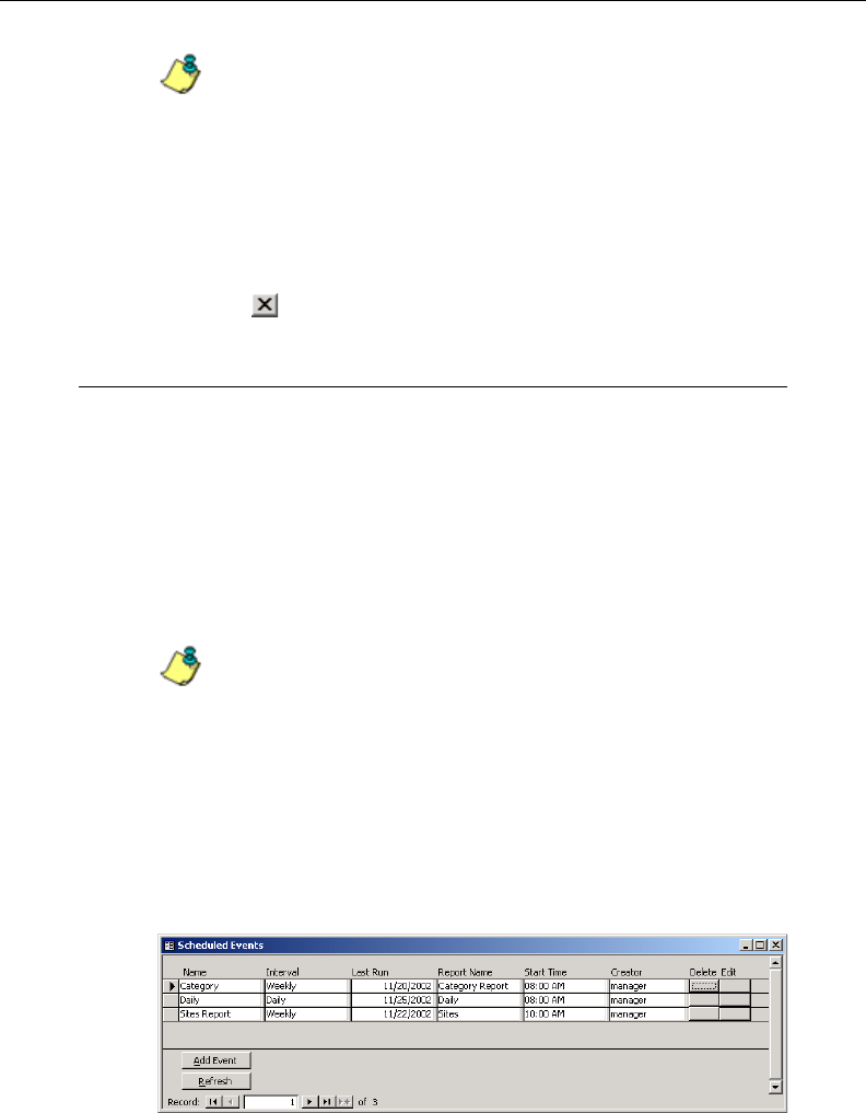
8E6 TECHNOLOGIES, ENTERPRISE REPORTER 3.0 USER’S GUIDE 109
CLIENT USER SECTION: CHAPTER 3 - CUSTOMIZING THE CLIENT
NOTE: If you are not the administrator, you will only see
options for Event Schedule, My Account, Server Statistics, and
Default Options. Details about the My Account option can be
found in the My Account sub-section.
Click a button in this menu to open boxes or windows used for
specifying your settings.
Click the in the upper corner of the Settings box to exit.
Event Schedule
The Event Schedule option is used for maintaining a sched-
ule for generating a customized report. For this option,
Windows’ task scheduler must be running on your machine,
and a customized report must previously have been saved
via the Record option. In order for the report to be automati-
cally generated, the Client must be closed at the time the
report is scheduled to run.
NOTE: See Appendix A: Scheduled Task Wizard for informa-
tion on setting up the task scheduler to run at a specified time.
More about saving reports using the Record option can be found
in Chapter 4, Using the Client, under the Record icon sub-section
in the Navigation bar section.
To view details on a scheduled event, or to edit, add, or delete
a scheduled event, click the Event Schedule button in the
Settings menu to open the Scheduled Events box:
Fig. 2:3-2 Scheduled Events box
110 8E6 TECHNOLOGIES, ENTERPRISE REPORTER 3.0 USER’S GUIDE
CLIENT USER SECTION: CHAPTER 3 - CUSTOMIZING THE CLIENT
Click the in the upper right corner of the Scheduled Events
box to exit this option.
View Details or Edit a Scheduled Event
In the Scheduled Events box, events display as rows of
records. The following information is included for each
record: Name assigned to the scheduled event, Interval when
the report is scheduled to run, date Last Run, Report Name,
Start Time for the report to run, and Creator of the schedule
(login username).
In the Record field at the bottom of the box, the number of the
selected record displays, along with the total number of
records (scheduled events).
TIP: The selected record is designated by an arrow in the grey
box to the left of a row. To select another record, click the grey box
in that row to display the arrow. You also can select another
record by clicking any of the four arrow buttons in the Record
field. In the order in which they display in the Record field, clicking
these buttons moves you to the first record, the record prior to the
selected record, the record following the selected record, and the
last record.
View Details for a Scheduled Event
To view additional information on an event, click the grey
button in the Edit column for that event. This action opens the
Add Event to Schedule dialog box:
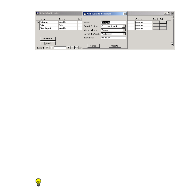
8E6 TECHNOLOGIES, ENTERPRISE REPORTER 3.0 USER’S GUIDE 111
CLIENT USER SECTION: CHAPTER 3 - CUSTOMIZING THE CLIENT
The following information displays in this dialog box: Name
assigned to the scheduled event, selected Report to Run,
interval When to Run the report, Day of the Week to run the
report if the report is a daily report, and Start Time to run.
Edit a Scheduled Event
1. In the Scheduled Events box, click the grey button in the
Edit column for the event you wish to modify. This action
opens the Add Event to Schedule dialog box. In this dialog
box you can:
•change the Name of the report
•make different selections as necessary from the pull-
down menus for Report to Run, When to Run, and/or
Day of the Week
•change the Start Time for running the report
TIP: Click Cancel if you wish to return to the Scheduled Events
box without saving your edits.
2. Click the Update button. This action opens an alert box with
the message: “Event added to schedule”.
3. Click OK to close both the alert box and the Add Event to
Schedule dialog box.
4. Click the Refresh button to display your edits in the Sched-
uled Events box.
Fig. 2:3-3 Add Event to Schedule dialog box and Scheduled Events
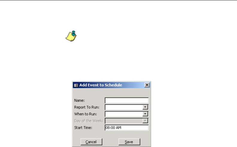
112 8E6 TECHNOLOGIES, ENTERPRISE REPORTER 3.0 USER’S GUIDE
CLIENT USER SECTION: CHAPTER 3 - CUSTOMIZING THE CLIENT
Schedule an Event
NOTE: To schedule an event, a report must already have
been saved using the Record option.
1. In the Scheduled Events box, click the Add Event button to
open the Add Event to Schedule dialog box:
2. Enter a Name for the event.
3. Select the Report to Run from the pull-down menu.
4. Select the frequency When to Run from the pull-down
menu (Daily, Weekly, or Monthly).
If Weekly, specify the Day of the Week from the pull-down
menu.
5. Enter the Start Time for the report.
6. Click Save to open an alert box with the message: “Event
added to schedule”.
7. Click OK to close both the alert box and the Add Event to
Schedule dialog box.
8. Click the Refresh button to display the event in the Sched-
uled Events box.
Fig. 2:3-4 Add Event to Schedule
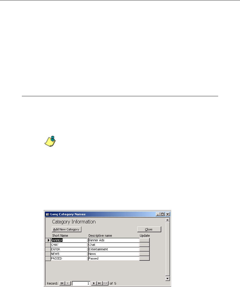
8E6 TECHNOLOGIES, ENTERPRISE REPORTER 3.0 USER’S GUIDE 113
CLIENT USER SECTION: CHAPTER 3 - CUSTOMIZING THE CLIENT
Delete a Scheduled Event
1. In the Scheduled Events box, click the grey button in the
Delete column for the event you wish to delete. This action
opens a dialog box with the message: “Are you sure you
want to delete this event?”
2. Click Yes or No to execute your action and to close the
dialog box.
Category Descriptions
The Category Descriptions option is used for viewing, updat-
ing, and adding category names and descriptions of filtering
categories used by the Web access logging device(s).
NOTE: When logs are imported each hour, new categories
found by the Server are automatically entered and will display in
the Client. The Server generates a short name for the category
and also uses this name as the descriptive “long” name.
To view details on a filter category, or to update or add a filter
category, click the Category Descriptions button in the
Settings menu to open the Category Information box:
To exit this option, click Close.
Fig. 2:3-5 Category Information box
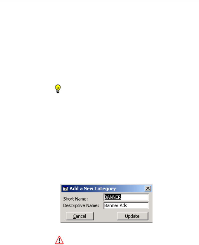
114 8E6 TECHNOLOGIES, ENTERPRISE REPORTER 3.0 USER’S GUIDE
CLIENT USER SECTION: CHAPTER 3 - CUSTOMIZING THE CLIENT
View Details for a Filter Category
In the Category Information box, filter categories display as
rows of records. The following information is included for
each record: Short Name of the category, and its correspond-
ing Descriptive name.
In the Record field at the bottom of the box, the number of the
selected record displays, along with the total number of
records (categories).
TIP: The selected record is designated by an arrow in the grey
box to the left of a row. To select another record, click the grey box
in that row to display the arrow. You also can select another
record by clicking any of the four arrow buttons in the Record
field. In the order in which they display in the Record field, clicking
these buttons moves you to the first record, the record prior to the
selected record, the record following the selected record, and the
last record.
Update a Filter Category
1. Click the grey button in the Update column for the category
you wish to modify. This action opens the Add a New
Category dialog box:
WARNING: While the Short Name can be edited, 8e6
recommends that you do not change this name. Doing so will
make that filter category unusable.
Fig. 2:3-6 Update a Filter Category
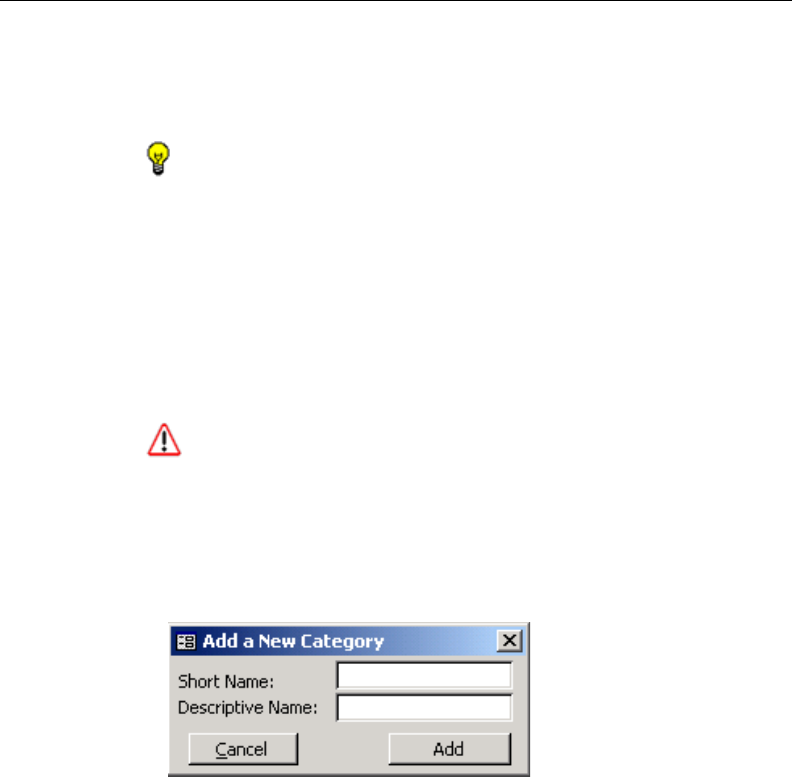
8E6 TECHNOLOGIES, ENTERPRISE REPORTER 3.0 USER’S GUIDE 115
CLIENT USER SECTION: CHAPTER 3 - CUSTOMIZING THE CLIENT
2. Edit the Descriptive Name. This description for the filter
category displays in the Categories column on the report
screen.
TIP: Click Cancel to return to the Category Information box
without saving your edits.
3. Click Update to accept your modifications and to open the
alert box with the message: “Category Updated!”
4. Click OK to close both the alert box and the dialog box. The
update you made displays in the Category Information box.
Add a Filter Category
WARNING: Any filter category you add can be edited but
cannot be deleted.
1. If you wish to add a filter category, in the Category Informa-
tion box, click the Add New Category button. This action
opens the Add a New Category dialog box:
2. Enter up to seven characters without spaces for the filter
category’s Short Name.
3. Enter the Descriptive Name. This entry will display as the
filter category’s description in the Categories column on the
report screen.
Fig. 2:3-7 Add a Filter Category
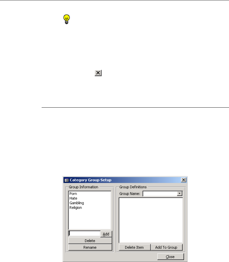
116 8E6 TECHNOLOGIES, ENTERPRISE REPORTER 3.0 USER’S GUIDE
CLIENT USER SECTION: CHAPTER 3 - CUSTOMIZING THE CLIENT
TIP: Click Cancel to return to the Category Information box
without saving your entries.
4. Click Add to open an alert box displaying the message:
“New Category Added!”
5. Click OK to close the alert box.
6. Click the in the upper right corner of the dialog box to
close it. The new category entry displays in the Category
Information box.
Category Groupings
The Category Groupings option is used for defining a cus-
tomized group of filter categories, if you wish to run reports
using certain filter categories only.
To create, edit, or delete a category group, click the Category
Groupings button in the Settings menu to open the Category
Group Setup box:
Fig. 2:3-8 Category Group Setup box

8E6 TECHNOLOGIES, ENTERPRISE REPORTER 3.0 USER’S GUIDE 117
CLIENT USER SECTION: CHAPTER 3 - CUSTOMIZING THE CLIENT
The Category Group Setup box is comprised of two frames
used for setting up and maintaining category groupings:
Group Information, and Group Definitions.
To exit this option, click Close.
Group Information frame
The Group Information frame displays to the left in the Cat-
egory Group Setup box. In this frame you can add, rename,
or delete a category group.
Any category groups that were created display in the list box
in this frame.
Add a Category Group
1. In the field to the left of the Add button, type in the name for
the category group.
2. Click the Add button to add this entry to the list box above,
and to open an alert box displaying the message: “Group
added successfully!”
3. Click OK to close the alert box.
NOTE: The category group you added also displays in the
Group Name pull-down menu in the Group Definitions frame to
the right.
Rename a Category Group
1. Select the category group from the list box by clicking on
your choice to highlight it.
2. Click the Rename button to open the Group Rename
dialog box:
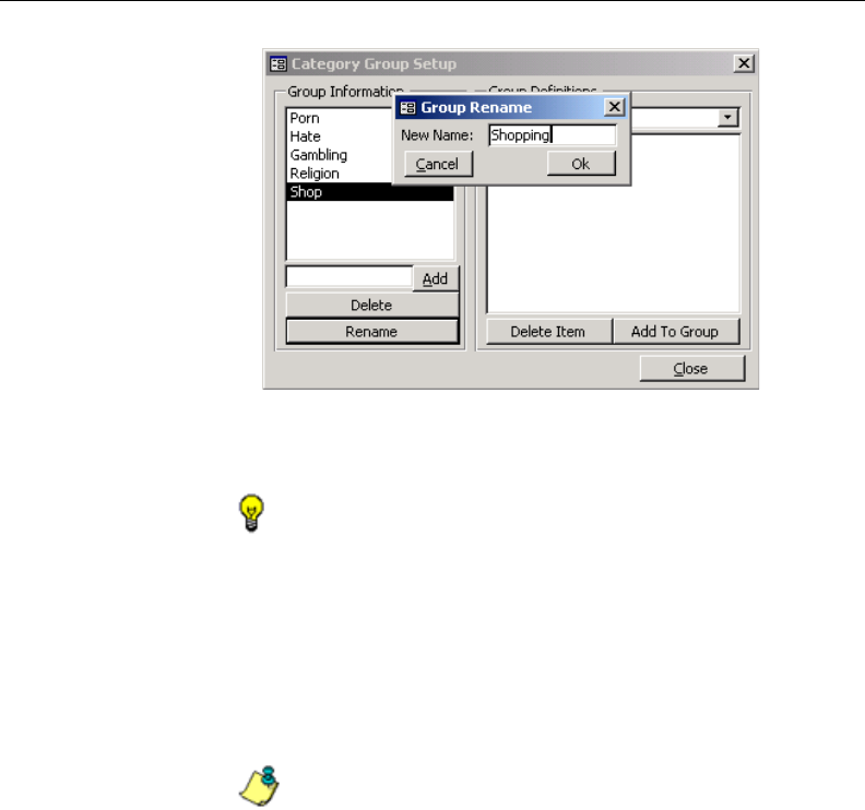
118 8E6 TECHNOLOGIES, ENTERPRISE REPORTER 3.0 USER’S GUIDE
CLIENT USER SECTION: CHAPTER 3 - CUSTOMIZING THE CLIENT
3. In the New Name field, edit the category group name.
TIP: Click Cancel if you wish to return to the Category Group
Setup box without saving your modifications.
4. Click Ok to close the Group Rename dialog box and to
open an alert box displaying the message: “Group re-
named successfully!”
5. Click OK to close the alert box and to update the list box in
the Group Information frame with your edits.
NOTE: The category group you renamed also displays in the
Group Name pull-down menu in the Group Definitions frame to
the right.
Delete a Category Group
1. Select the category group from the list box by clicking on
your choice to highlight it.
2. Click the Delete button to remove the category group from
the list box and to open an alert box displaying the mes-
sage: “Group deleted successfully!”
Fig. 2:3-9 Edit a Category Group Name

8E6 TECHNOLOGIES, ENTERPRISE REPORTER 3.0 USER’S GUIDE 119
CLIENT USER SECTION: CHAPTER 3 - CUSTOMIZING THE CLIENT
3. Click OK to close the alert box.
NOTE: The category group you deleted also is removed
from the Group Name pull-down menu in the Group Definitions
frame to the right.
Group Definitions frame
The Group Definitions frame displays to the right in the
Category Group Setup box. In this frame you define a cat-
egory group by specifying which categories will belong to that
group.
Add Categories to a Category Group
1. Select a category group from the Group Name pull-down
menu. Any categories previously entered display in the list
box in this frame.
2. Click the Add To Group button to open the Add To Group
popup box.
3. Select a category from the popup box by clicking on your
choice to highlight it.
4. To select the next category from the list, press the Ctrl key
on your keyboard, then use the mouse to click on the
category to highlight it.
5. After all categories for the group are selected, click the Add
To Group button in the popup box to display the alert box
with the message: “Categories Added!”
6. Click OK to close the alert box, and to add all selected
categories to the list box in the Group Definitions frame:
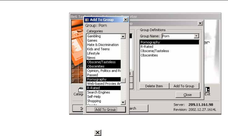
120 8E6 TECHNOLOGIES, ENTERPRISE REPORTER 3.0 USER’S GUIDE
CLIENT USER SECTION: CHAPTER 3 - CUSTOMIZING THE CLIENT
7. Click the in the upper right corner of the Add To Group
popup box to close it.
Delete a Category from a Category Group
1. Select a category group from the Group Name pull-down
menu to display in the list box all categories for that cat-
egory group.
2. Select the category to be removed by clicking on your
choice to highlight it.
3. Click the Delete Item button to display the alert box with the
message: “Group deleted successfully!”
4. Click OK to close the alert box and to remove the category
from the list box for that category group.
Fig. 2:3-10 Add Categories to the Category Group
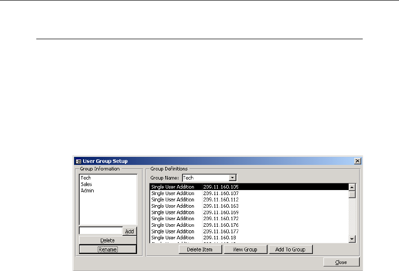
8E6 TECHNOLOGIES, ENTERPRISE REPORTER 3.0 USER’S GUIDE 121
CLIENT USER SECTION: CHAPTER 3 - CUSTOMIZING THE CLIENT
User Groupings
The User Groupings option is used for defining a customized
group of users, if you wish to run reports for certain users
only.
To create, edit, or delete a user group, click the User Group-
ings button in the Settings menu to open the User Group
Setup box:
The User Group Setup box is comprised of two frames used
for setting up and maintaining user groupings: Group Infor-
mation, and Group Definitions.
To exit this option, click Close.
Group Information frame
The Group Information frame displays to the left in the User
Group Setup box. In this frame you can add, rename, or
delete a user group.
Any user groups that were created display in the list box in
this frame.
Fig. 2:3-11 User Group Setup box
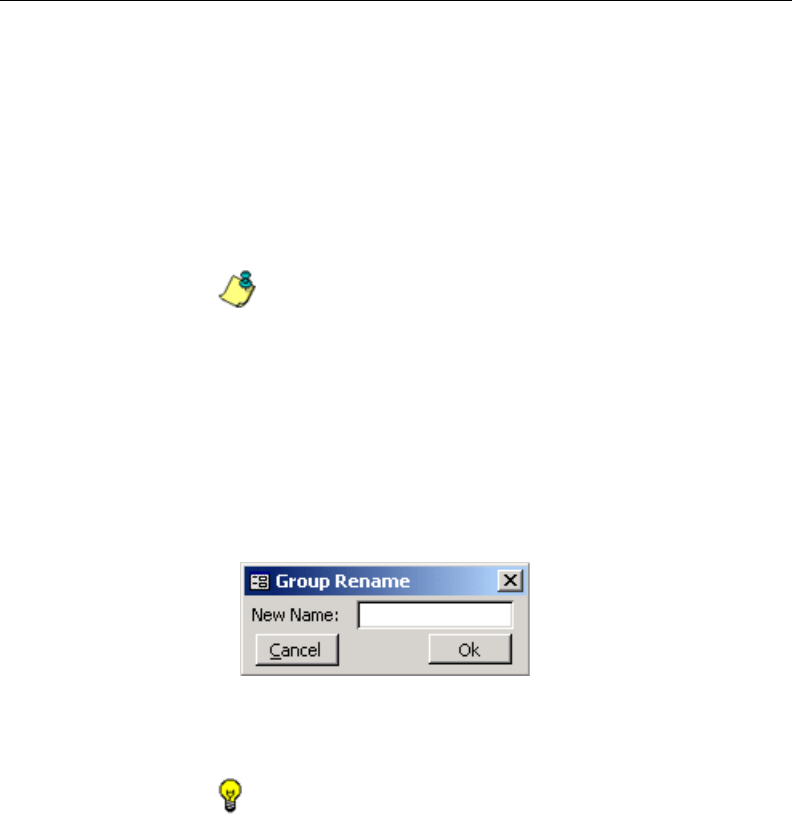
122 8E6 TECHNOLOGIES, ENTERPRISE REPORTER 3.0 USER’S GUIDE
CLIENT USER SECTION: CHAPTER 3 - CUSTOMIZING THE CLIENT
Add a User Group
1. In the field to the left of the Add button, type in the name for
the user group.
2. Click the Add button to add this entry to the list box above,
and to display the message: “Group added successfully!”
3. Click OK to close the alert box.
NOTE: The user group you added also displays in the Group
Name pull-down menu in the Group Definitions frame to the right.
Rename a User Group
1. Select the user group from the list box by clicking on your
choice to highlight it.
2. Click the Rename button to open the Group Rename
dialog box:
3. In the New Name field, edit the user group name.
TIP: Click Cancel if you wish to return to the User Group Setup
box without saving your modifications.
4. Click Ok to close the Group Rename dialog box and to
open an alert box displaying the message: “Group re-
named successfully!”
5. Click OK to close the alert box and to update the list box in
the Group Information frame with your edits.
Fig. 2:3-12 Group Rename dialog box

8E6 TECHNOLOGIES, ENTERPRISE REPORTER 3.0 USER’S GUIDE 123
CLIENT USER SECTION: CHAPTER 3 - CUSTOMIZING THE CLIENT
NOTE: The user group you renamed also displays in the
Group Name pull-down menu in the Group Definitions frame to
the right.
Delete a User Group
1. Select the user group from the list box by clicking on your
choice to highlight it.
2. Click the Delete button to remove the user group from the
list box and to open an alert box displaying the message:
“Group deleted successfully!”
3. Click OK to close the alert box.
NOTE: The user group you deleted also is removed from the
Group Name pull-down menu in the Group Definitions frame to
the right.
Group Definitions frame
The Group Definitions frame displays to the right in the User
Group Setup box. In this frame you can view members of a
user group, and can define a user group by specifying which
users will belong to that group.
View a List of Users in a User Group
1. Select a user group from the Group Name pull-down
menu. Any users previously entered display in the list box in
this frame.
2. To view the entire list of users in a different format, click the
the View Group button to open the Users in User Group
popup box:
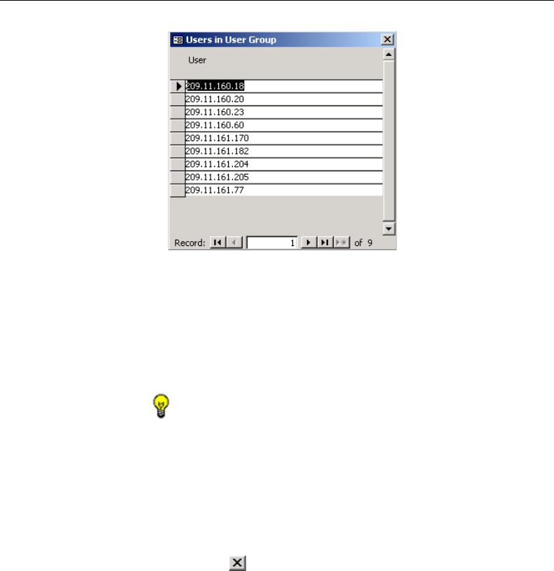
124 8E6 TECHNOLOGIES, ENTERPRISE REPORTER 3.0 USER’S GUIDE
CLIENT USER SECTION: CHAPTER 3 - CUSTOMIZING THE CLIENT
Each user entered for the user group displays as a sepa-
rate record in this popup box. In the Record field at the
bottom of the box, the number of the selected record
displays, along with the total number of records (catego-
ries).
TIP: The selected record is designated by an arrow in the grey
box to the left of a row. To select another record, click the grey box
in that row to display the arrow. You also can select another
record by clicking any of the four arrow buttons in the Record
field. In the order in which they display in the Record field, clicking
these buttons moves you to the first record, the record prior to the
selected record, the record following the selected record, and the
last record.
3. Click the in the upper right corner of the popup box to
close it.
Define a User Group
When defining a user group, you can add and/or exclude
users to/from that group. Modifications to a user group can be
made at any time, as necessary.
Fig. 2:3-13 Users in User Group popup box
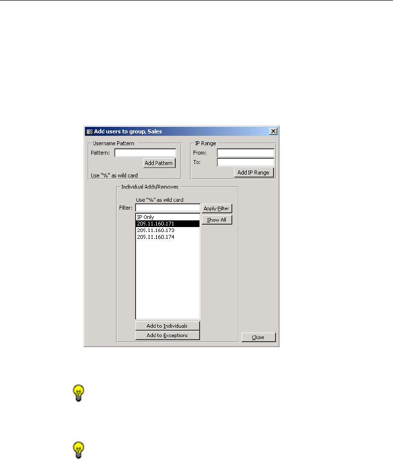
8E6 TECHNOLOGIES, ENTERPRISE REPORTER 3.0 USER’S GUIDE 125
CLIENT USER SECTION: CHAPTER 3 - CUSTOMIZING THE CLIENT
1. Select a user group from the Group Name pull-down
menu. Any users previously entered display in the list box in
this frame.
2. Click the Add To Group button to open the popup box
where you define users to be added/excluded to/from the
group:
TIP: To view a list of all users, go to the Individual Adds/
Removes frame and click the Show All button to display the list of
users in the list box.
TIP: To clear your entries in this popup box without accepting
them, do not click any of the buttons in the frames described
below. Instead, click the Close button in the popup box, and
return to step 1.
Fig. 2:3-14 Add Users to group

126 8E6 TECHNOLOGIES, ENTERPRISE REPORTER 3.0 USER’S GUIDE
CLIENT USER SECTION: CHAPTER 3 - CUSTOMIZING THE CLIENT
3. Make entries in one of the three frames:
• Username Pattern - This frame is used for including
users from a specific group (such as “Sales”) on the
network. In the Pattern field, enter the appropriate
characters and wild card “%” to add specified users to
the group. For example, type in Sales% to add anyone to
the group who has a “Sales” designation on your net-
work. Click the Add Pattern button to open an alert box
with the message: “Pattern Added!” Click OK to close
the alert box.
• IP Range - This frame is used for including users based
on a range of IP addresses. For example, you might
have one range of IP addresses for Sales, and another
for Admin. Enter the IP address range in the From and
To fields. Click the Add IP Range button to open an alert
box with the message: “IP Range Added!” Click OK to
close the alert box.
• Individual Adds/Removes - This frame is used for
including and/or excluding specified users. Click the
Show All button to display a list of all users in the list box.
To narrow down the list of users, make an entry in the
Filter field using the “%” wild card, and click the Apply
Filter button to only display the users you specified. To
select from users in the list box, click on the user(s) to
highlight your choice(s). After making all choices, click
Add to Individuals to include the selected users to the
group, or click Add to Exceptions to exclude the users
from the group.
TIP: In the Individual Adds/Removes frame, if you know which
users you would like to add/exclude to/from the group, you can
bypass the step for showing all users and making your selections.
To use this shortcut, enter the criteria in the Filter field along with
the “%” wild card, and then click the Apply Filter button to display
your results in the list box.

8E6 TECHNOLOGIES, ENTERPRISE REPORTER 3.0 USER’S GUIDE 127
CLIENT USER SECTION: CHAPTER 3 - CUSTOMIZING THE CLIENT
4. After you have made your entries, click Close to close the
popup box.
5. Refresh the display in the Group Definitions frame list box
by making another selection from the Group Name pull-
down menu, then re-selecting the user group you just set
up or modified.
The following information displays in the Group Definitions
frame list box when a selection is made from the Group
Name pull-down menu:
•If an entry was made in the Username Pattern frame,
“Username Pattern” and the character(s) you entered
display(s).
•If entries were made in the IP Range frame, “IP RANGE”
“Between...AND...” (including the IP addesses) dis-
plays.
•If entries were made in the Individual Adds/Removes
frame, “Single User Addition” and/or “Single User
Exception” (including each user added/excluded)
displays.
NOTE: A combination of any of items above may display in
the Group Definitions frame list box, based on entries you made
in any of the frames in the popup box.
Delete a User
1. Select a user group from the Group Name pull-down
menu. Any users previously entered display in the list box in
this frame.
2. Click on the user to highlight your selection.
3. Click the Delete Item button to remove the user from the
user group and to display an alert box with the message:
“Group deleted successfully!”
4. Click OK to close the alert box.
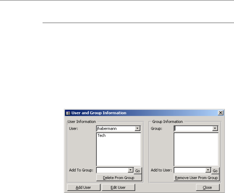
128 8E6 TECHNOLOGIES, ENTERPRISE REPORTER 3.0 USER’S GUIDE
CLIENT USER SECTION: CHAPTER 3 - CUSTOMIZING THE CLIENT
User Permissions
The User Permissions option is used for giving authorization
to personnel such as managers to view reports for their
group and to change their own passwords. This option
requires a user group to be set up via the User Groupings
option from the Settings menu.
To assign permissions, or to edit permissions that have been
assigned, click the User Permissions button in the Settings
menu to open the User and Group Information box:
Using the User and Group Information box, you can maintain
the list of users and user groups set up to access the Client.
To exit this option, click Close.
Add User
When adding a user who will be authorized to access the
Client, you must first set up the user’s username and pass-
word, then specify the group(s) in which the user will belong.
Fig. 2:3-15 User and Group Information box
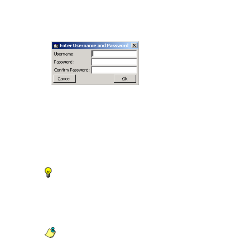
8E6 TECHNOLOGIES, ENTERPRISE REPORTER 3.0 USER’S GUIDE 129
CLIENT USER SECTION: CHAPTER 3 - CUSTOMIZING THE CLIENT
1. Click the Add User button to open the Enter Username and
Password dialog box:
2. Type in the Username.
3. Type in the alphanumeric Password in upper- and/or
lowercase characters. Your entry displays as a series of
asterisks for security purposes.
4. Type in the same characters in the Confirm Password
field.
TIP: Click Cancel if you wish to return to the User and Group
Information box without saving your entries.
5. Click Ok to open an alert box displaying the message:
“User Added!”
6. Click OK to close both the alert box and the dialog box.
NOTE: The username is added to the User pull-down menu
in the User Information frame. When the User and Group Infor-
mation box is refreshed (by clicking the Close button to close it,
then clicking the User Permissions button in the Settings menu to
re-open it), the username also displays in the Add to User pull-
down menu in the Group Information frame.
Fig. 2:3-16 Add User

130 8E6 TECHNOLOGIES, ENTERPRISE REPORTER 3.0 USER’S GUIDE
CLIENT USER SECTION: CHAPTER 3 - CUSTOMIZING THE CLIENT
You must now add the user to a user group by making entries
in either the User Information frame or the Group Information
frame. While both frames contain similar contents, each
serves a different function. The User Information frame is
used for maintaining a list of authorized users, while the
Group Information frame is used for maintaining user groups.
User Information frame
In the User Information frame, you can add a user to a user
group, or remove a user from a user group.
Add User to a User Group
1. Select the User from the pull-down menu. If the user has
been added to other groups, these groups display in the list
box below.
2. From the Add To Group pull-down menu, select the group
to which the user should be added.
3. Click Go to open an alert box displaying the message:
“Group added.”
4. Click OK to close the alert box and to display the group
name in the list box above.
Remove User from a User Group
1. Select the User from the pull-down menu. The user’s
group(s) display(s) in the list box below.
2. Select the group from which the user should be removed by
clicking on your choice to highlight it.
3. Click the Delete From Group button to remove the group
from the list box, and to open an alert box displaying the
message: “Removed from group.”
4. Click OK to close the alert box.

8E6 TECHNOLOGIES, ENTERPRISE REPORTER 3.0 USER’S GUIDE 131
CLIENT USER SECTION: CHAPTER 3 - CUSTOMIZING THE CLIENT
Group Information frame
In the Group Information frame, you update user groups by
adding or removing users.
Update User Group by Adding a User
1. Select the Group from the pull-down menu. Any users
added to this user group display in the list box below.
2. From the Add To User pull-down menu, select the user to
be added to the group.
3. Click Go to open an alert box displaying the message:
“User added.”
4. Click OK to close the alert box and to display the user name
in the list box above.
Update User Group by Removing a User
1. Select the Group from the pull-down menu. Any users
added to this user group display in the list box below.
2. Select the user to be removed from the group by clicking on
your choice to highlight it.
3. Click the Remove User From Group button to remove the
user from the list box, and to open an alert box displaying
the message: “Removed!”
4. Click OK to close the alert box and to remove the user from
the list box.
Edit Password or Delete User
By clicking the Edit User button in the User and Group Infor-
mation box, the User Information dialog box displays. In this
dialog box you can change a user’s password, or delete a
user.
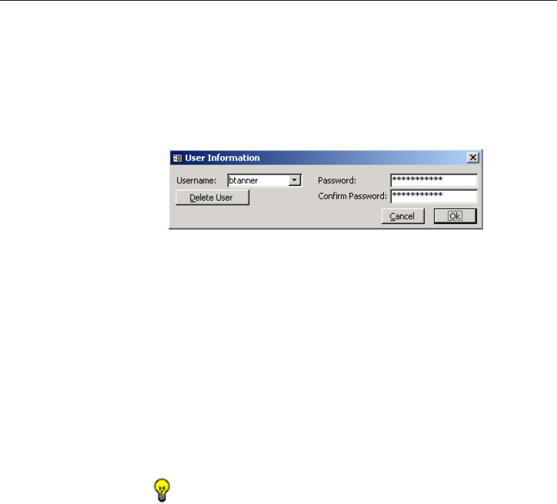
132 8E6 TECHNOLOGIES, ENTERPRISE REPORTER 3.0 USER’S GUIDE
CLIENT USER SECTION: CHAPTER 3 - CUSTOMIZING THE CLIENT
Change a User’s Password
1. In the User and Group Information box, click the Edit User
button to open the User Information dialog box.
2. Select the user from the Username pull-down menu:
3. In the Password field, clear the asterisks that display by
pressing the spacebar on your keyboard.
Type in the new alphanumeric password in upper- and/or
lowercase characters. Your entry displays as a series of
asterisks for security purposes.
4. Press the Tab key on your keyboard to move to the Con-
firm Password field.
Type in the same characters you entered in the Password
field.
TIP: Click Cancel if you wish to return to the User and Group
Information box without saving your entries.
5. Click Ok to open an alert box displaying the message:
“Password Updated!”
6. Click OK to close both the alert box and the User Informa-
tion dialog box.
Delete a User
1. In the User and Group Information box, click the Edit User
button to open the User Information dialog box.
Fig. 2:3-17 Edit user password, delete user
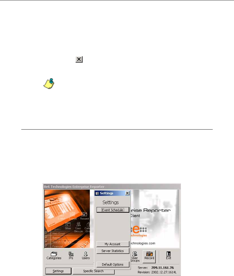
8E6 TECHNOLOGIES, ENTERPRISE REPORTER 3.0 USER’S GUIDE 133
CLIENT USER SECTION: CHAPTER 3 - CUSTOMIZING THE CLIENT
2. Select the user from the Username pull-down menu.
3. Click the Delete User button to open an alert box display-
ing the message: “User deleted!”
4. Click OK to close the alert box.
5. Click the in the upper right corner of the User Informa-
tion dialog box to close it.
NOTE: The username is removed from the choices in the
User pull-down menu in the User Information frame, and from the
choices in the Add to User pull-down menu in the Group Informa-
tion frame.
My Account
The My Account option displays only for non-administrator
users who have been set up (by the administrator) to access
the Client. When a non-administrator user logs into the Client
and clicks the Settings button, the Settings menu displays as
follows:
Fig. 2:3-18 Settings menu, non-administrator user
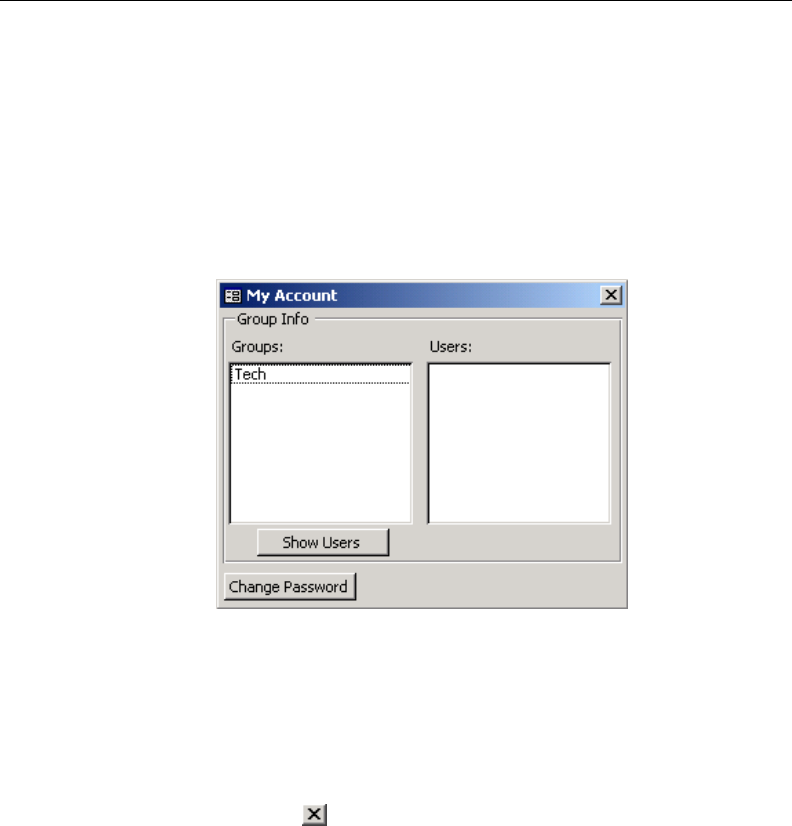
134 8E6 TECHNOLOGIES, ENTERPRISE REPORTER 3.0 USER’S GUIDE
CLIENT USER SECTION: CHAPTER 3 - CUSTOMIZING THE CLIENT
Options available to the user include: Event Schedule, My
Account, Server Statistics, and Default Options.
My Account is used for viewing a list of users who are in-
cluded in your user group(s), and for updating your password.
To access your account, click the My Account button to open
the My Account box:
Upon accessing My Account, any user group to which your
username has been assigned (via the User Permissions
option from the Settings menu) displays in the Groups list
box.
Click the in the upper right corner of the My Account box to
exit this option.
View Users in a User Group
To view a list of users in your user group:
1. In the Groups list box, select the user group by clicking on
your choice to highlight it.
Fig. 2:3-19 My Account box
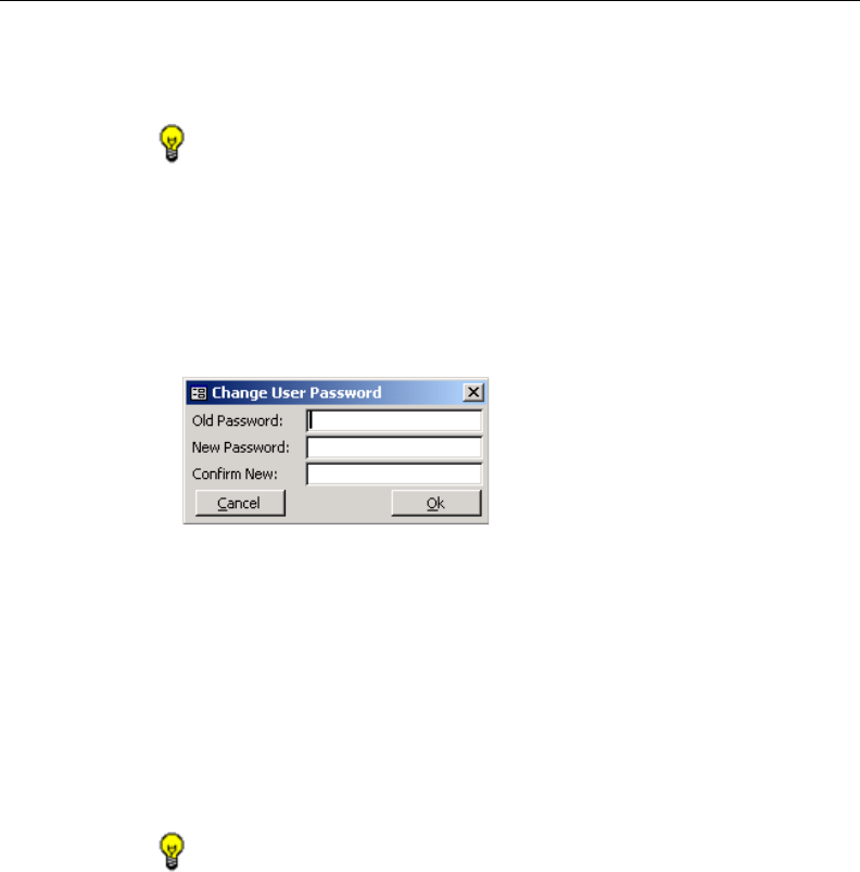
8E6 TECHNOLOGIES, ENTERPRISE REPORTER 3.0 USER’S GUIDE 135
CLIENT USER SECTION: CHAPTER 3 - CUSTOMIZING THE CLIENT
2. Click the Show Users button to display the users in the
Users list box to the right.
TIP: If there is another user group listed that you wish to view,
follow the steps above to view the usernames in that user group.
Change Password
1. Click the Change Password button to open the Change
User Password dialog box:
2. Type in the Old Password. Your entry displays as a series
of asterisks for security purposes.
3. Type in the alphanumeric New Password in upper- and/or
lowercase characters. Your entry displays as a series of
asterisks for security purposes.
4. Type in the same characters for the new password in the
Confirm New field.
TIP: Click Cancel if you wish to return to the My Account box
without saving your entries.
5. Click Ok to open an alert box displaying the message:
“Password Changed!”
6. Click OK to close both the alert box and the dialog box.
Fig. 2:3-20 Change User Password
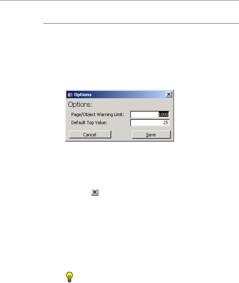
136 8E6 TECHNOLOGIES, ENTERPRISE REPORTER 3.0 USER’S GUIDE
CLIENT USER SECTION: CHAPTER 3 - CUSTOMIZING THE CLIENT
Default Options
Default Options is used for setting the maximum number of
records to be included in a report, and the number of records
that will display on a report screen.
Click the Default Options button in the Settings menu to open
the Options box:
The Page/Object Warning Limit default is “1000” and the
Default Top Value default is “25”.
Click the in the upper right corner of the Options box to exit
this option.
Set New Defaults
1. Enter the maximum Page/Object Warning Limit for the
query results.
2. Enter the Default Top Value of records that will display on
the screen.
TIP: Click Cancel to exit without saving your entries.
3. Click the Save button to save your settings and to exit the
Options box.
Fig. 2:3-21 Options box
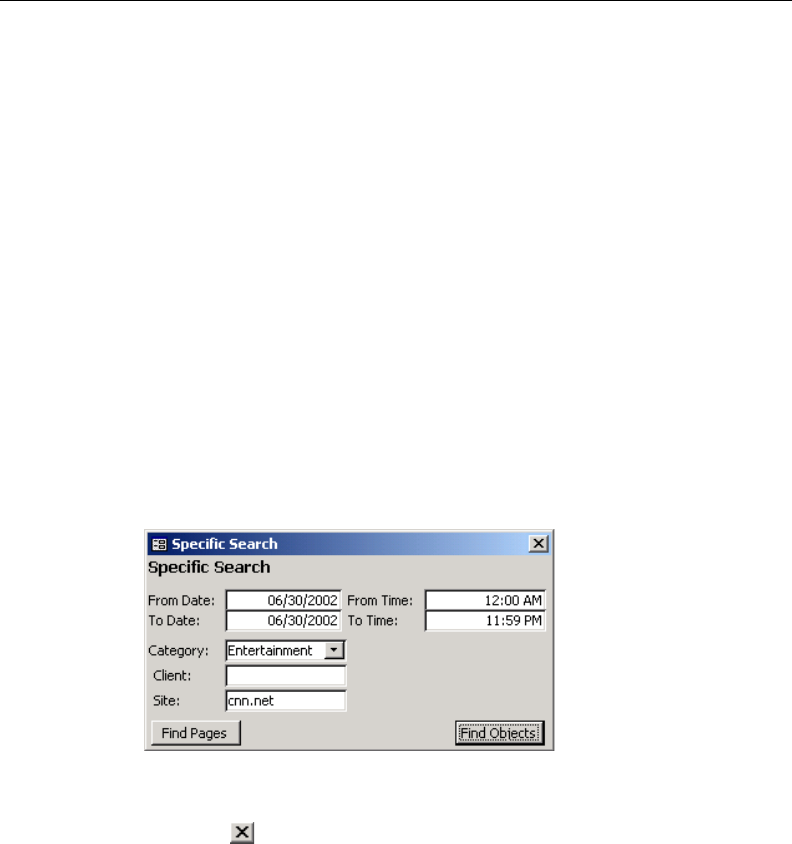
8E6 TECHNOLOGIES, ENTERPRISE REPORTER 3.0 USER’S GUIDE 137
CLIENT USER SECTION: CHAPTER 4 - USING THE CLIENT
Chapter 4: Using the Client
Once the Client has been customized, you can query the
database and generate reports. This chapter provides ex-
amples on the many ways in which the Client can be used for
fulfilling your reporting needs.
Specific Search Function
The Specific Search function is used for performing a search
for pages or objects viewed by a specified user, or for per-
forming a search for pages or objects users viewed within a
specified filter category and/or at a specified Web site.
From the main menu, click the Specific Search button to
open the Specific Search box:
Click the in the upper right corner of the Specific Search
box to exit this option.
When using the specific search function, you must specify
the date and time range for the search, the type of search you
wish to perform (Category, Client, Site), and the type of items
to be included in the search (Pages or Objects).
Fig. 2:4-1 Specific Search option
138 8E6 TECHNOLOGIES, ENTERPRISE REPORTER 3.0 USER’S GUIDE
CLIENT USER SECTION: CHAPTER 4 - USING THE CLIENT
Specify Time Frame for the Search
You must first specify a date and time range for your query.
1. Click in the From Date field and enter the first date in the
range, using the format on your machine (e.g. 12/01/2002
could be entered if the MM/DD/YYYY format is used).
TIP: When entering dates in this box, forward slash (“/”)
symbols should not be entered, as they are static components of
the Date fields. To clear an entry in a Date field, press the Back
Space key.
Press the Tab key to move to the To Date field.
2. Enter the last date in the range, using the format on your
machine.
Press the Tab key to move to the From Time field.
3. Enter the beginning time using the HH:MM format (e.g.
03:00), and type in either “am” or “pm”.
TIP: When entering times in this box, colon (“:”) symbols
should not be entered, as they are static components of the Time
fields. To clear an entry in a Time field, press the Back Space key.
Press the Tab key to move to the To Time field.
4. Enter the ending time using the HH:MM format, and type in
either “am” or “pm”.

8E6 TECHNOLOGIES, ENTERPRISE REPORTER 3.0 USER’S GUIDE 139
CLIENT USER SECTION: CHAPTER 4 - USING THE CLIENT
Specify Type of Search to be Performed
In the next step for specifying search criteria, you must
indicate if you wish to perform the search on the activity of a
specific filter category, user, and/or Web site. Specify your
search type in one or more of the following fields: Category,
Client, Site.
• Category - to perform a search on activity within a specific
filter category, make a selection from the filter categories in
the pull-down menu. Category items are set up under the
Category Descriptions option from the Settings menu.
• Client - to perform a search on the activity of a specific
user, enter either the username (e.g. “tjohnson”) or IP
address of the user’s machine (e.g. “209.11.160.174”).
• Site - to perform a search on activity at a specific Web site
visited by clients (users), enter the domain or site address
(e.g. “yahoo.com” or “icq.com”).
Specify Items to be Searched, View Results
In the final step for specifying your search criteria, you must
indicate the type of items you wish to search: Pages or
Objects.
• Find Pages - click this button to search for Web pages that
were accessed. Results display in a report in your browser
window showing the Date and URL for each Web page
matching the search criteria. A hyperlink to the page is
included so you can visit that page.
• Find Objects - click this button to search for objects that
were viewed (image files, JavaScript files, flash files, etc.).
Results display in a report in your browser window showing
the Date and URL for each object matching the search
criteria. A hyperlink to the object is included so you can visit
that item.
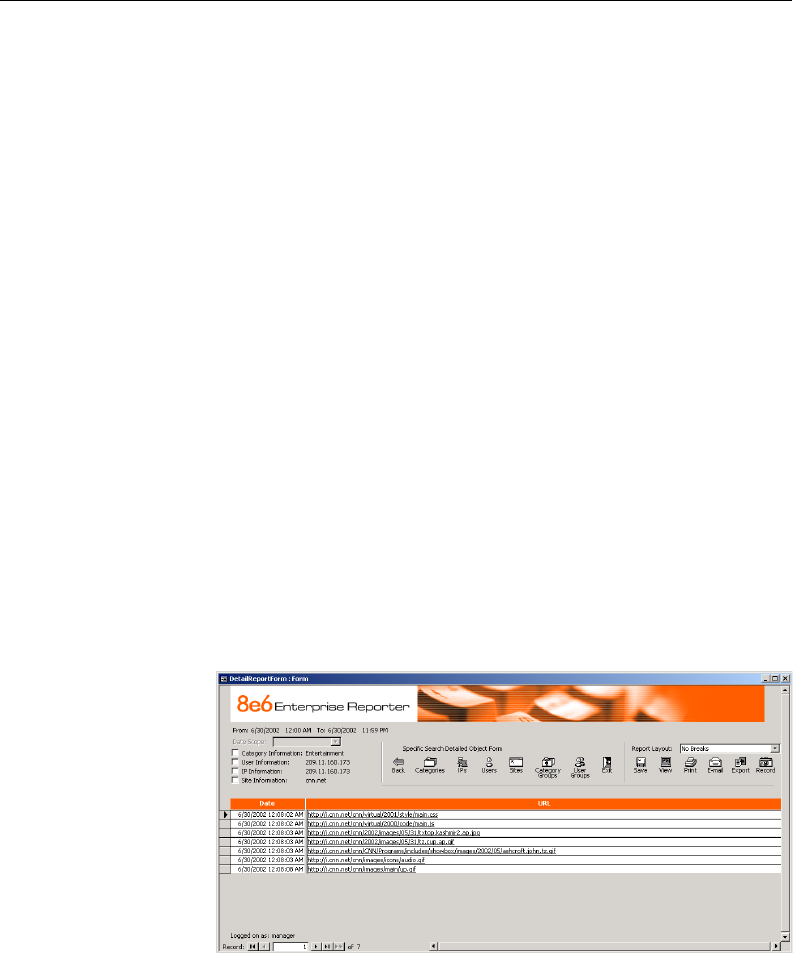
140 8E6 TECHNOLOGIES, ENTERPRISE REPORTER 3.0 USER’S GUIDE
CLIENT USER SECTION: CHAPTER 4 - USING THE CLIENT
Warning Messages
Page Search
When the Find Pages button is clicked, if the date and time
range that was specified is outside the scope of live data
currently stored on the Server, a warning message displays
to inform you that if you wish to proceed, the report will take a
longer amount of time to generate.
Object Search
When the Find Objects button is clicked:
•If the date and time range that was specified includes both
live and archive data currently stored on the Server, a
warning message displays to inform you that if you wish to
proceed, only the objects that still exist on the Server will
display.
•If objects no longer exist on the Server for the date and time
range that was specified, a message displays to inform you
that these objects no longer exist on the Server.
Fig. 2:4-2 Find Objects search results

8E6 TECHNOLOGIES, ENTERPRISE REPORTER 3.0 USER’S GUIDE 141
CLIENT USER SECTION: CHAPTER 4 - USING THE CLIENT
View Additional Information
To view additional data, click in the Information checkbox
corresponding to Category, User, IP, and/or Site to add the
selected column(s) to the online report. To remove a column
from the online report, click to remove the check mark.
• Category - clicking in this checkbox adds the Category
column to the report, listing the filter category to which the
item belongs.
• User - clicking in this checkbox adds the User column to
the report, listing the username or IP address of the user
who accessed or viewed the item.
•IP - clicking in this checkbox adds the User IP column to the
report, listing the IP address of the user’s machine that
accessed the item.
• Site - clicking in this checkbox adds the Site column to the
report, listing the item’s domain name or site address.
This online report can be saved, viewed, printed, distributed,
and/or captured for repetitive execution. More information on
reporting options can be found throughout this chapter, and in
Chapter 5: Reports.
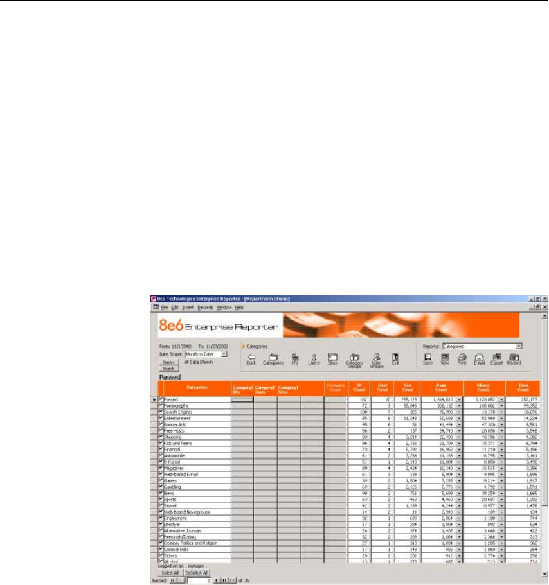
142 8E6 TECHNOLOGIES, ENTERPRISE REPORTER 3.0 USER’S GUIDE
CLIENT USER SECTION: CHAPTER 4 - USING THE CLIENT
Report Screen Elements
Report screens are accessible by clicking on icons for Cat-
egories, IPs, Users, or Sites from the main menu or any
report screen. If category groupings or user groupings have
been defined via the Settings menu option, Category Groups
or User Groups report screens are additionally available by
clicking on icons for these topics.
Though each screen displays data pertinent to your specifica-
tions, all screens have basic elements in common. Under-
standing the function of these elements is critical, since the
usage of these tools determines the results of your query.
The top of the report screen displays the date range for the
selected Date Scope, the type of data (Top or All) selected to
Display, the navigation path for the current report view, and
the report view selection made at the Reports field.
Fig. 2:4-3 Categories report
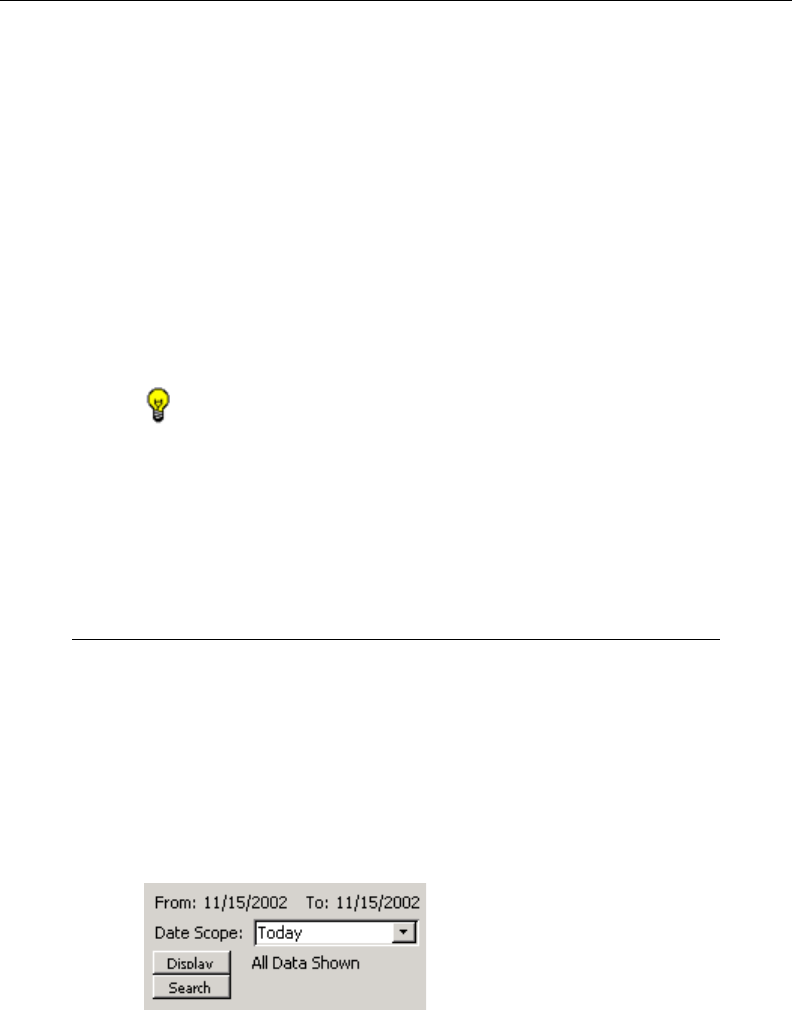
8E6 TECHNOLOGIES, ENTERPRISE REPORTER 3.0 USER’S GUIDE 143
CLIENT USER SECTION: CHAPTER 4 - USING THE CLIENT
The body of the report includes columns pertinent to the
report selection that was made, populated by rows of records
resulting from the query. Each row is preceded by a
checkbox. After each record, columns of grey filter boxes
display. These boxes are followed by columns of statistics for
tracking user activity on the Internet by Category Count, IP
Count, User Count or Site Count, and by Page Count, Object
Count, and Time Count. A down arrow displays to the right of
the Page Count and Object Count for each record. By clicking
this arrow, a report for that record displays. More about Page/
Object reports is explained in subsequent sub-sections, and
in Chapter 5: Reports.
TIP: Pages/objects must exist within the date scope that was
specified in order to be viewed.
The bottom of the report screen displays the username of the
login ID used for this session (Logged on as), the Record
number currently selected, and the last number in the range
of records obtained by the query.
Date Scope
The Date Scope field is located at the top left portion of the
screen. Make a selection from the pull-down menu for the
time frame you wish to use in your query: Month to Date,
Monthly, Year to Date, Daily, Yesterday, Today, Month to
Yesterday, Year to Yesterday. The range of dates within the
specified scope displays above the Date Scope field. Reports
can be run for any data saved in the ER 3.0’s memory.
Fig. 2:4-4 Date Scope field
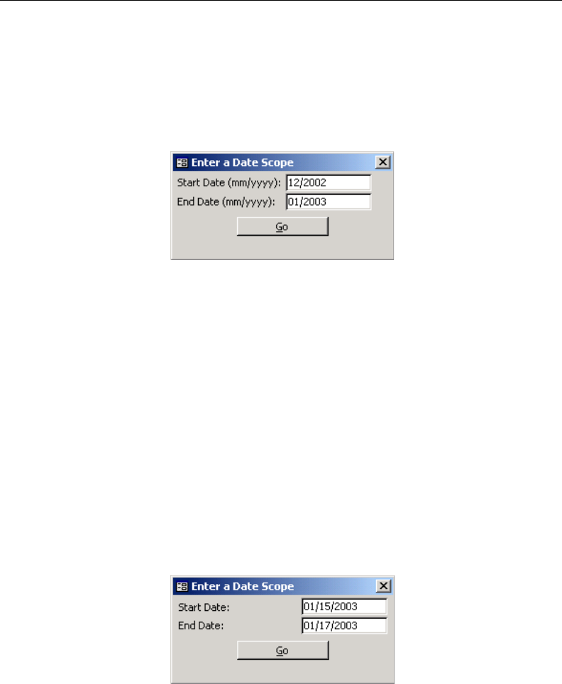
144 8E6 TECHNOLOGIES, ENTERPRISE REPORTER 3.0 USER’S GUIDE
CLIENT USER SECTION: CHAPTER 4 - USING THE CLIENT
• Month to Date - this option generates the report for the
range of days that includes the first day of the current
month through today.
• Monthly - selecting this option opens the Enter a Date
Scope box where you specify the range of months:
Enter the Start Date and End Date using the MM/YYYY
format, and click Go to close the box. The generated report
includes the first date of the specified month in the speci-
fied year, and the last date of the specified month in the
specified year. For example, if “12/2002” is entered for the
Start Date and “01/2003” is entered for the End Date, the
screen displays the date range as 12/1/2002 to 1/31/2003.
• Year to Date - this option generates the report for the range
of days that includes the first day of the current year
through today.
• Daily - selecting this option opens the Enter a Date Scope
box where you specify the range of days:
Fig. 2:4-5 Entries for Monthly option
Fig. 2:4-6 Entries for Daily option
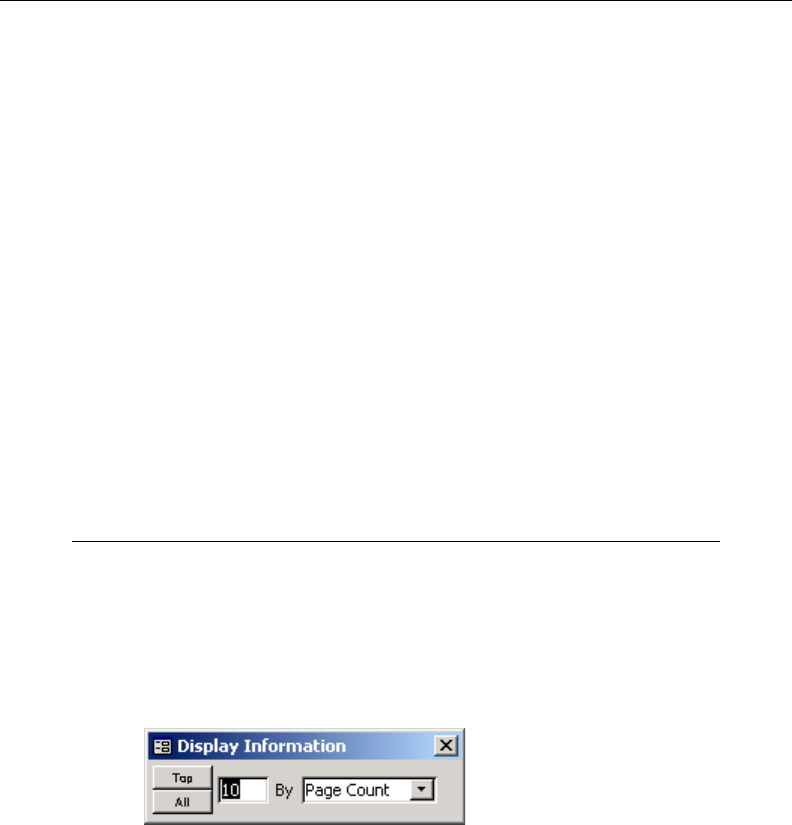
8E6 TECHNOLOGIES, ENTERPRISE REPORTER 3.0 USER’S GUIDE 145
CLIENT USER SECTION: CHAPTER 4 - USING THE CLIENT
Enter the Start Date and End Date using the MM/DD/
YYYY format, and click Go to close the box. The generated
report includes data for the specified days only, if the data
for these days are stored on the Server.
• Yesterday - this option generates the report for yesterday
only.
• Today - this option generates the report for today only, if
logs from the Web access logging device have been
received and processed.
• Month to Yesterday - this option generates the report for
the range of days that includes the first day of the current
month through yesterday.
• Year to Yesterday - this option generates the report for the
range of days that includes the first day of the current year
through yesterday.
Display button
The Display button is located beneath the Date Scope field.
Click the Display button to open the Display Information box
where you specify the number of records you wish to view on
the screen and include in the report, and how these records
will be sorted in the generated report.
Specify the manner in which records will be sorted by select-
ing an available choice from the pull-down menu: Category
Count, IP Count, User Count, Object Count, Page Count, Site
Count, or Time Count. Each of these selections corresponds
to an available column on the report screen.
Fig. 2:4-7 Display Information box
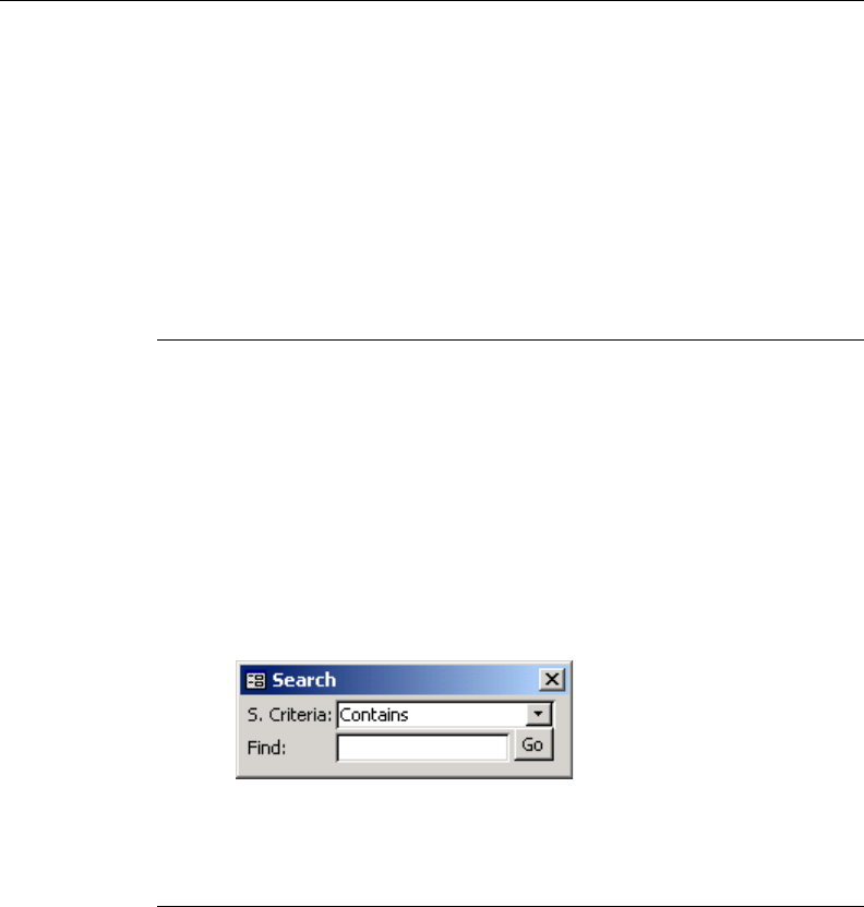
146 8E6 TECHNOLOGIES, ENTERPRISE REPORTER 3.0 USER’S GUIDE
CLIENT USER SECTION: CHAPTER 4 - USING THE CLIENT
To include only top records, enter the number of records and
click the Top button. To include all records, click the All
button.
By clicking one of these buttons, the box closes and the
screen displays rows of records corresponding to the number
of records specified, and a label (to the right of this Display
button) showing the specified criteria.
Search button
The Search button is located beneath the Display button.
Click the Search button to open the Search box and specify
your search terms for items in the current report.
At the S(earch) Criteria field, choose from the following
items: Contains, Starting With, Ending In. Enter the text in the
Find field, and click Go to display the results of your query on
the screen. To perform another search, click the Back icon in
the navigation bar located beneath the navigation path.
Navigation path
The navigation path displays to the right of the Date Scope
field. This path shows your location in the Client for the
current session. For example, if you are on the main screen
of the Categories report, the navigation path will read “Cat-
egories.” If you are in the Users section of a specific category,
the path would read “Category/Users.” By noting the path,
you can easily locate the view again during the same session.
Fig. 2:4-8 Search box
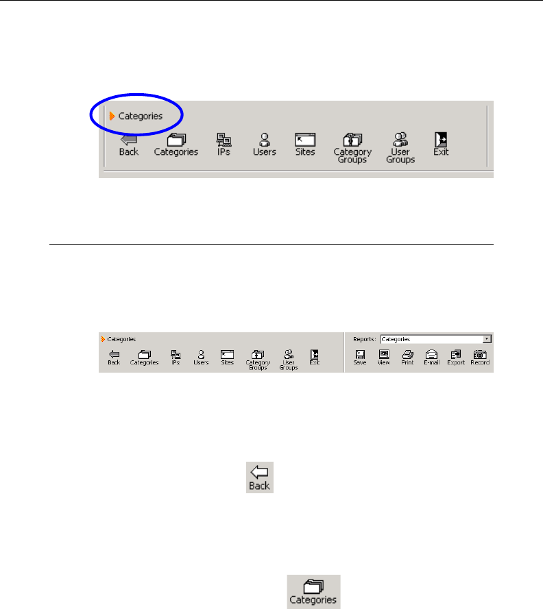
8E6 TECHNOLOGIES, ENTERPRISE REPORTER 3.0 USER’S GUIDE 147
CLIENT USER SECTION: CHAPTER 4 - USING THE CLIENT
To return to a previous report view, click the Back icon in the
navigation bar located beneath the navigation path.
Navigation bar
The navigation bar, located beneath the navigation path,
includes a row of icons and the Reports (or Report Layout)
pull-down menu:
Back icon
Clicking the Back icon returns you to a prior screen, if
you have viewed other reports during this session.
Categories icon
Clicking the Categories icon displays the report
showing categories set up for your Web access logging
device(s).
Fig. 2:4-10 Navigation bar
Fig. 2:4-9 Navigation path
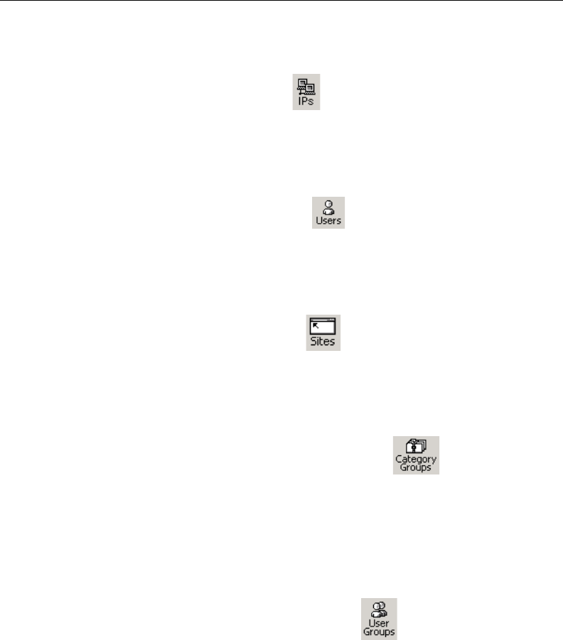
148 8E6 TECHNOLOGIES, ENTERPRISE REPORTER 3.0 USER’S GUIDE
CLIENT USER SECTION: CHAPTER 4 - USING THE CLIENT
IPs icon
Clicking the IPs icon displays the report sorted by user IP
address.
Users icon
Clicking the Users icon displays the report sorted by
username.
Sites icon
Clicking the Sites icon displays the report sorted by
visited sites.
Category Groups icon
Clicking the Category Groups icon displays the
report sorted by user-defined category groups, if category
groupings were previously estabished under the Settings
menu option.
User Groups icon
Clicking the User Groups icon displays the report
sorted by user-defined user groups, if user groupings were
previously established under the Settings menu option.
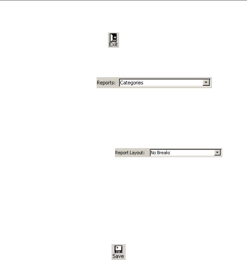
8E6 TECHNOLOGIES, ENTERPRISE REPORTER 3.0 USER’S GUIDE 149
CLIENT USER SECTION: CHAPTER 4 - USING THE CLIENT
Exit icon
Clicking the Exit icon returns you to the main menu.
Reports / Report Layout field
The Reports field
displays on Categories, IPs, Users, Sites, Category Groups,
and User Groups report screens. Make a selection from the
Reports pull-down menu. Reports in the standard report
format are available for all main report groups. Pie chart and
bar chart formats are available for Categories, Category
Groups, and User Groups reports.
The Report Layout field
displays on Page and Object report screens. Make a selec-
tion from the Report Layout pull-down menu for the type of
report you wish to view.
Save icon
The Save option lets you capture the report that currently
displays on your screen. A generated report format is used for
the saved report.
Clicking the Save icon opens the Output To dialog box in
which you specify the output format for the report:
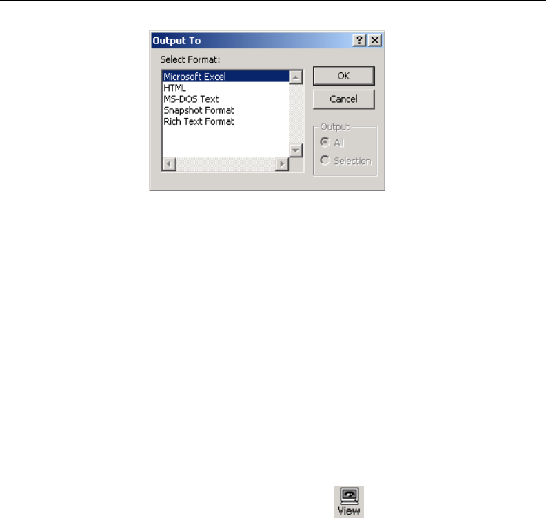
150 8E6 TECHNOLOGIES, ENTERPRISE REPORTER 3.0 USER’S GUIDE
CLIENT USER SECTION: CHAPTER 4 - USING THE CLIENT
Choose the output format from the list box by clicking on your
selection: Microsoft Excel (.xls), HTML (.html), MS-DOS Text
(.txt), Snapshot Format (.snp) or Rich Text Format (.rtf).
Click OK to close the Output To dialog box, and to open the
Output To popup window where you save the report to a
designated folder in the specified output format.
View icon
The View option helps you make any necessary adjustments
to your report settings prior to printing the report. To use this
feature, you must have a printer configured for your machine.
When clicking the View icon , one of three actions
occurs, depending on the report options you selected:
• the report displays in a window
• the Double Break Information dialog box opens
• the Generate Chart box opens
Fig. 2:4-11 Output To dialog box

8E6 TECHNOLOGIES, ENTERPRISE REPORTER 3.0 USER’S GUIDE 151
CLIENT USER SECTION: CHAPTER 4 - USING THE CLIENT
View, Print the Report
The report displays in a window: The report automatically
displays in a window when the View icon is clicked for any of
the following scenarios:
• when a standard report from one of the main report groups
(“IPs,” “Users,” etc.) is selected.
• when a filter selection is specified for the report (see the
Filters sub-section).
• when the report is an object/page report (see Page/Object
Reports from Chapter 5: Reports).
In the report window, you can zoom in or out by clicking the
middle of the page with the magnifying glass icon. If the
report includes more than one page, click the arrow buttons
at the bottom of the window. In the order in which they display
in this window, clicking these buttons moves you to the first
page, the page prior to the displayed page, the page following
the displayed page, and the last page.
To change the orientation of the page, select File > Page
Setup from the toolbar at the top of the window which opens
the Page Setup dialog box where you specify Portrait or
Landscape on the Page tab.
To print the report from this window, select File > Print from
the toolbar at the top of the window which opens the Print
dialog box where you specify your printing options.
To close this window, click the in the upper right corner of
the window.
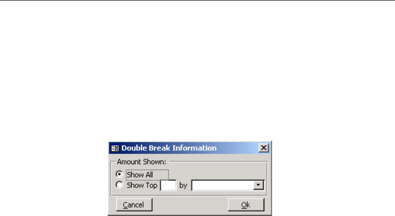
152 8E6 TECHNOLOGIES, ENTERPRISE REPORTER 3.0 USER’S GUIDE
CLIENT USER SECTION: CHAPTER 4 - USING THE CLIENT
Double Break Information dialog box
The Double Break Information dialog box opens: If you
made a selection from the Reports pull-down menu to view a
standard report with two main sort groups (such as “Cat-
egory/IPs” or “Sites/Users,” etc.), and then click the View
icon, you will be prompted to specify viewing/printing criteria
in the Double Break Information dialog box.
Entries made in this dialog box are similar to those made in
the Display Information box, accessible via the Display
button. However, entries in the Double Break Information
dialog box further define how the generated report will display
and print.
Specify the manner in which records will be viewed/printed by
selecting an available choice from the pull-down menu:
Category Count, IP Count, User Count, Object Count, Page
Count, Site Count, or Time Count. Each of these selections
corresponds to an available column on the report screen.
To include only top records, enter the number of records and
click the Top button. To include all records, click the All
button.
After making selections in this box, click OK to close the box
and to view the report in a window. (See View, Print the
Report for view/print options.)
Fig. 2:4-12 Double Break dialog box
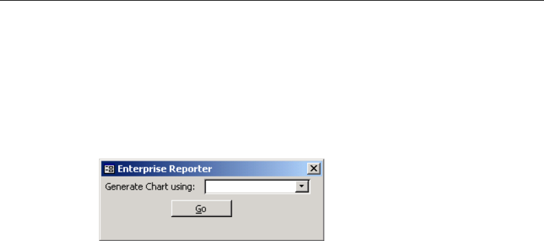
8E6 TECHNOLOGIES, ENTERPRISE REPORTER 3.0 USER’S GUIDE 153
CLIENT USER SECTION: CHAPTER 4 - USING THE CLIENT
Generate Chart box
The Generate Chart box opens: If you made a selection
from the Reports pull-down menu to view a report in the pie
chart or bar chart format, you will be prompted to specify
viewing/printing criteria in the Generate Chart box.
Entries made in this box further define how the generated
report will display and print.
Make a selection from choices available in the pull-down
menu: Category Count, IP Count, User Count, Object Count,
Page Count, Site Count, or Time Count. Each of these
selections corresponds to an available column on the report
screen.
After making your selection in this box, click Go to close the
box and to view the report in a window. (See View, Print the
Report for view/print options.)
Fig. 2:4-13 Generate Chart box
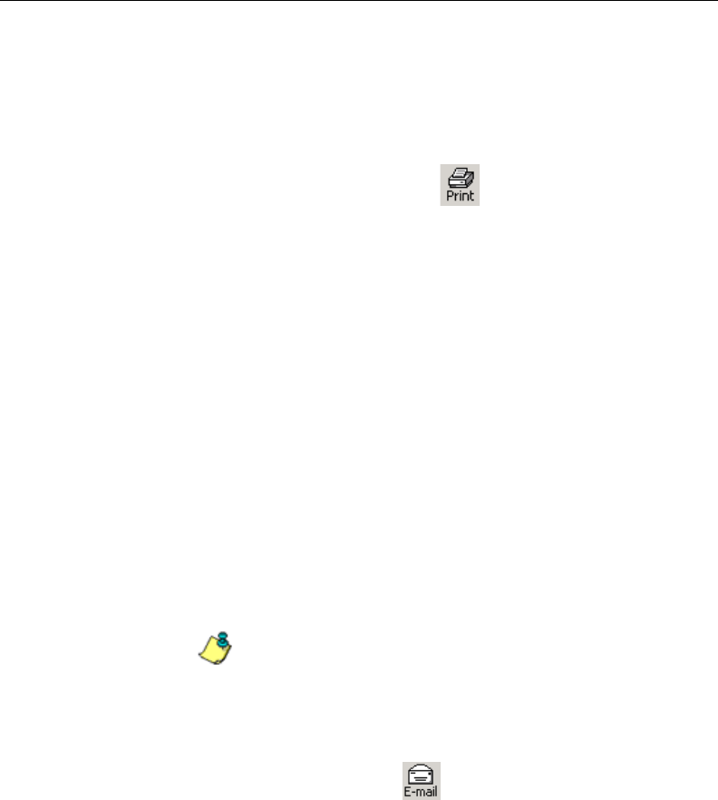
154 8E6 TECHNOLOGIES, ENTERPRISE REPORTER 3.0 USER’S GUIDE
CLIENT USER SECTION: CHAPTER 4 - USING THE CLIENT
Print icon
To use the Print option, you must have a printer configured for
your machine.
When clicking the Print icon , one of three actions
occurs, depending on the report options you selected:
• the report prints to your printer
• the Double Break Information dialog box opens
• the Generate Chart box opens
See the View icon section for information about the Double
Break Information dialog box and the Generate Chart box.
After making selections from either box, click OK or Go to
close the box and to print the report to your printer.
E-mail icon
The E-mail option lets you e-mail the report that currently
displays on your screen.
NOTE: If you are using Lotus Notes as your primary e-mail
client instead of Microsoft Outlook or Outlook Express, refer to
Appendix B for information on how to configure Lotus Notes to
work with the ER 3.0 Client.
Clicking the E-mail icon opens the E-mail Report dialog
box in which you enter the e-mail address(es) of the
recipient(s) in the To field. If necessary, enter e-mail criteria in
the following fields: Cc, Bcc, Subject, Body.
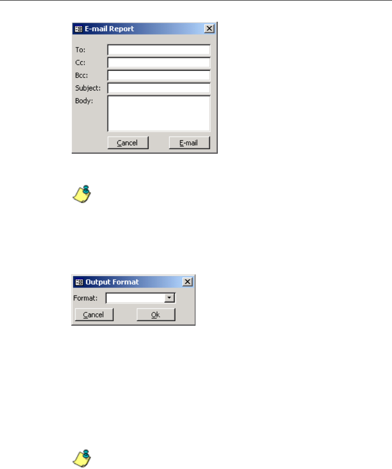
8E6 TECHNOLOGIES, ENTERPRISE REPORTER 3.0 USER’S GUIDE 155
CLIENT USER SECTION: CHAPTER 4 - USING THE CLIENT
NOTE: If a Subject is not specified, the report received by
the recipient(s) will display “Enterprise Reporter - Report” in the
Subject line of the e-mail message.
Click the E-mail button to open the Output Format box:
From the Format pull-down menu, choose the output format
for the report: Microsoft Excel (.xls), MS-DOS Text (.txt),
Snapshot Format (.snp), or Rich Text Format (.rtf).
Click Ok to dispatch the e-mail. The report is sent as an
attachment to the e-mail message.
NOTE: The report attached to the e-mail message will look
like the report that is saved when using the Save option for
Microsoft Excel, MS-DOS Text, Snapshot Format, or Rich Text
Format.
Fig. 2:4-14 E-mail Report box
Fig. 2:4-15 Output Format box
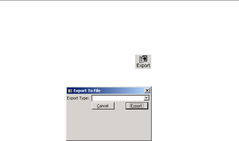
156 8E6 TECHNOLOGIES, ENTERPRISE REPORTER 3.0 USER’S GUIDE
CLIENT USER SECTION: CHAPTER 4 - USING THE CLIENT
Export icon
The Export option lets you export raw data from the report
that displays on your screen.
Clicking the Export icon opens the Export To File box
in which you specify the format for exporting the raw data.
From the Export Type pull-down menu, choose the format
for the report: Ansii Text File (*.txt), Comma Delimited Text
File (*.csv), Microsoft Excel File (*.xls), HTML File (*.html), or
Rich Text File (*.rtf).
Click the Export button to open the Save File popup window
to designate where the exported data will be saved.
Fig. 2:4-16 Export to File box

8E6 TECHNOLOGIES, ENTERPRISE REPORTER 3.0 USER’S GUIDE 157
CLIENT USER SECTION: CHAPTER 4 - USING THE CLIENT
Record icon
The Record option lets you save data from a custom report
you create. This custom report can be generated and then
viewed, printed, e-mailed, or saved in a selected file format.
Report specifications can be edited via the Open a Recorded
Report option, defined in this sub-section. A custom report
can be scheduled to run at a specified interval using the
Event Schedule option.
NOTE: Information on using the Event Schedule option can
be found in Chapter 3: Customizing the Client, in the Settings
section, Event Schedule sub-section. In order for the report to run
as scheduled, the Client must be closed. The Client will automati-
cally open and generate the report at the scheduled time, and
then close after completing the task.
Clicking the Record icon opens a dialog box (“Save
Custom Report” or “Save as Custom Report”) that lets you
record details for the report you wish to generate.
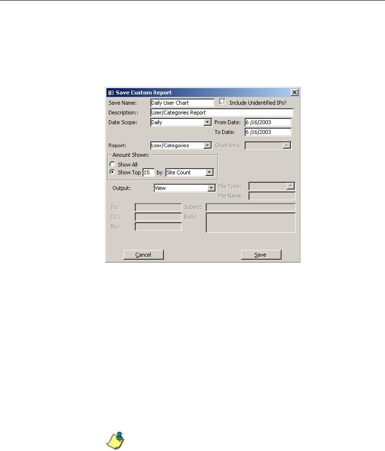
158 8E6 TECHNOLOGIES, ENTERPRISE REPORTER 3.0 USER’S GUIDE
CLIENT USER SECTION: CHAPTER 4 - USING THE CLIENT
Save Custom Report dialog box
The Save Custom Report dialog box opens for any report that
is not a page or object report:
Enter the report name in the Save Name field, and then enter
a Description for the report. Click in the Include Unidenti-
fied IPs? checkbox if you wish to include the IP Only record
in reports. This record includes activity from machines that
are not assigned to specific users.
In the Date Scope field, choose from the following dates:
Today, Yesterday, Month To Date, Year To Date, Daily, or
Monthly. If you choose Daily or Monthly, you must specify the
date range in the From Date and To Date fields.
NOTE: More information on Date Scope entries can be
found in this chapter, in the Date Scope sub-section.
Fig. 2:4-17 Save Custom Report dialog box

8E6 TECHNOLOGIES, ENTERPRISE REPORTER 3.0 USER’S GUIDE 159
CLIENT USER SECTION: CHAPTER 4 - USING THE CLIENT
The selection made at the Reports pull-down menu on the
report screen displays in the Report field. The default selec-
tion at this field can be changed, if necessary.
If the selected report format is either a pie or bar chart, the
Chart Info field is activated. Make a selection from the pull-
down menu for the manner in which you wish the report data
to be sorted. Options may include the following: Category
Count, IP Count, User Count, Object Count, Page Count, Site
Count, or Time Count.
In the Amount Shown frame, specify the amount of data you
wish to include in the report by clicking the radio button
corresponding to Show All or Show Top. If Show All is
selected, the report will include all records. If Show Top is
selected, specify the column Count type to be used (Cat-
egory, IP, User, Site, Page, Object, Time) based on the
available selections, as well as the number of records to be
included. The entries in this frame are similar to those made
in the Display Information box. (See the Display button sub-
section in this chapter.)
At the Output field, make a choice from the pull-down menu
to specify the output method for the report: Printer, File, E-
Mail, or View.
• If File is selected, the File Type and File Name fields be-
come activated. Choose the File Type from the pull-down
menu: Microsoft Excel, HTML, MS-DOS Text, Snapshot
Format, Rich Text Format. Enter a File Name for the report.
• If E-Mail is selected, the following fields become activated:
File Type, To, Cc, Bcc, Subject, and Body. Select the File
Type from the pull-down menu. Type in the e-mail
address(es) of the recipient(s) in the To field. If necessary,
enter e-mail critieria in the following fields: Cc, Bcc, Sub-
ject, Body.
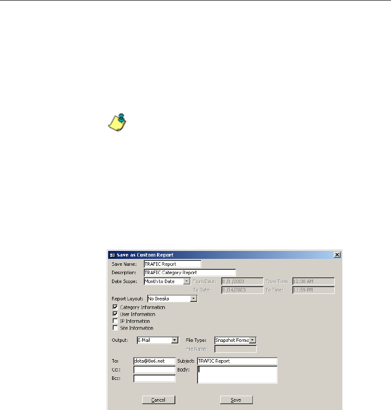
160 8E6 TECHNOLOGIES, ENTERPRISE REPORTER 3.0 USER’S GUIDE
CLIENT USER SECTION: CHAPTER 4 - USING THE CLIENT
When you click Save the alert box opens with the message:
“Custom Report has been saved”. Click OK to close the alert
box. The report will not run until you specify when you want it
to run, by using either the Open a Recorded Report option
defined in this sub-section, or the Event Schedule option and
task scheduler.
NOTE: If the Save Name you entered has already been
used, a message displays: “Name Already in use, Overwrite?”
You can choose to either overwrite the record with the current
report criteria, or rename the report.
Save as Custom Report dialog box
The Save as Custom Report dialog box opens for any page
or object report:
Enter the report name in the Save Name field, and then enter
a Description for the report.
Fig. 2:4-18 Save as Custom Report dialog box

8E6 TECHNOLOGIES, ENTERPRISE REPORTER 3.0 USER’S GUIDE 161
CLIENT USER SECTION: CHAPTER 4 - USING THE CLIENT
In the Date Scope field, choose from the following dates:
Yesterday, Month To Date, Year To Date, Part of Today, Part
of Yesterday, Daily, Monthly, or Part of Specific Day.
• If you choose Part of Today or Part of Yesterday, you must
specify the time range in the From Time and To Time
fields.
• If you choose Daily or Monthly, you must specify the date
range in the From Date and To Date fields.
• If you choose Part of Specific Day, you must specify the
From Date and make entries in the From Time and To
Time fields.
The selection made at the Report Layout pull-down menu on
the report screen displays in the Report Layout field. If
selections were made on the report screen for Category
Information, User Information, IP Information, or Site Infor-
mation, these selections display. Default selections from any
of these fields can be changed, if necessary.
At the Output field, make a choice from the pull-down menu
to specify the output method for the report: Printer, File, E-
Mail, or View.
• If File is selected, the File Type and File Name fields be-
come activated. Choose the File Type from the pull-down
menu: Microsoft Excel, HTML, MS-DOS Text, Snapshot
Format, Rich Text Format. Enter a File Name for the report.
• If E-Mail is selected, the following fields become activated:
File Type, To, Cc, Bcc, Subject, and Body. Select the File
Type from the pull-down menu. Type in the e-mail
address(es) of the recipient(s) in the To field. If necessary,
enter e-mail critieria in the following fields: Cc, Bcc, Sub-
ject, Body.
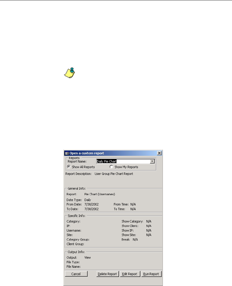
162 8E6 TECHNOLOGIES, ENTERPRISE REPORTER 3.0 USER’S GUIDE
CLIENT USER SECTION: CHAPTER 4 - USING THE CLIENT
When you click Save the alert box opens with the message:
“Custom Report has been saved”. Click OK to close the alert
box. The report will not run until you specify when you want it
to run, by using either the Open a Recorded Report option
defined in this sub-section, or the Event Schedule option and
task scheduler.
NOTE: If the Save Name you entered has already been
used, a message displays: “Name Already in use, Overwrite?”
You can choose to either overwrite the record with the current
report criteria, or rename the report.
Open a Recorded Report
By clicking the Record icon on the main menu, the Open a
custom report box opens:
Fig. 2:4-19 Open a custom report box

8E6 TECHNOLOGIES, ENTERPRISE REPORTER 3.0 USER’S GUIDE 163
CLIENT USER SECTION: CHAPTER 4 - USING THE CLIENT
TIP: Click Cancel to close this dialog box.
If you are logged in as a non-administrator, in the Reports
frame, click the radio button corresponding to either Show All
Reports or Show My Reports. By clicking the former, you
will view a list in the Report Name pull-down menu of all
recorded reports. By clicking the latter, you will view only the
reports you recorded. If you are logged in as an administrator,
you do not need to click either radio button, as all report
selections will display in the Report Name pull-down menu.
Make a selection from the Report Name pull-down menu to
populate the General Info, Specific Info, and Output Info
frames.
To remove the custom report from choices available in this
box, click Delete Report. A dialog box opens: “Are you sure
you wish to delete the report?” Click either Yes or No.
NOTE: If a custom report is scheduled to run via the Event
Schedule option, deleting the report removes it from the Sched-
uled Events box.
To re-open the Save Custom Report dialog box where you
can edit your report settings, click Edit Report. After making
your modifications, click Update to open the alert box: “Cus-
tom Report has been updated”. Click OK to close the alert
box.
To generate the custom report now, click Run Report.
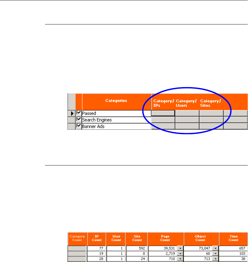
164 8E6 TECHNOLOGIES, ENTERPRISE REPORTER 3.0 USER’S GUIDE
CLIENT USER SECTION: CHAPTER 4 - USING THE CLIENT
Fig. 2:4-21 “Count” columns
Filters
A filter displays on the report screen as a grey box in a column
following the record name, and preceding the Count col-
umns. Each filter column is labeled for the function it will
perform. By clicking a specific filter button for a record, more
in-depth analysis is provided for that record.
Columns
Columns for specified “item counts” display in the body of all
report screens. By clicking a column header, all records in the
report will sort by that column. You can toggle between
ascending and descending counts by clicking the same
column header twice. The column for the current report type
does not display and therefore cannot be selected.
Fig. 2:4-20 Filters

8E6 TECHNOLOGIES, ENTERPRISE REPORTER 3.0 USER’S GUIDE 165
CLIENT USER SECTION: CHAPTER 4 - USING THE CLIENT
• Category Count - This column displays the number of
categories a user has visited, or the number of categories
included within a given site. Categories are set up for the
Web access logging device filter via the Settings menu
option. It is possible for a site to be listed in more than one
category, so even if a user has visited only one site, this
column may count the user’s visit in two or three catego-
ries.
• IP Count - This column displays the number of sites or
categories visited by the IP address on the user’s machine.
• User Count - This column displays the number of individu-
als who have visited a specific site or category.
• Site Count - This column displays the number of sites a
user has visited, or the number of sites in a category. This
figure is based on the root name of the site. For example, if
a user visits www.espn.com, www.msn.com, and
www.foxsports.com, that user will have visited three pages.
If that same user additionally visits www.espn.com/scores,
the total number of sites visited would still count as three—
and not as four—because the latter page is on the original
ESPN site that was already counted.
• Page Count - This column displays the total number of
pages visited. A user may visit only one site, but visit 20
pages on that site. If a user visits a page with popup ads,
these items would add to the page count. If a page has
banner ads that link to other pages, these items also would
factor into the page count. In categories that use a lot of
popup ads—porn, gambling, and other related sites—the
page count usually exceeds the number of objects per
page.
By clicking the down arrow to the right of any record in this
column, a report screen displays with details for all pages
visited, including hyperlinks to those pages. On this screen,
you have the option to include Information columns for
Category, User, IP, and Site by clicking in the checkboxes.

166 8E6 TECHNOLOGIES, ENTERPRISE REPORTER 3.0 USER’S GUIDE
CLIENT USER SECTION: CHAPTER 4 - USING THE CLIENT
TIP: If the date range that was specified at the Date Scope
field is outside the scope of live data currently stored on the
Server, when clicking the down arrow, a warning message
displays to inform you that if you wish to proceed, the report will
take a longer amount of time to generate.
• Object Count - This column displays the number of objects
on a Web page. All images, graphics, multimedia items,
and text items count as objects. The number of objects on a
page is generally higher than the number of pages a user
visits.
However, if an advertisement or banner ad (an object on
the page) is actually a page from another site, this item
would not be classified as an object but as a page, since it
comes from a different server.
By clicking the down arrow to the right of any record in this
column, a report screen displays with details for all pages
visited, including hyperlinks to those pages. On this screen,
you have the option to include Information columns for
Category, User, IP, and Site by clicking in the checkboxes.
TIP: If the date range that was specified at the Date Scope
field includes both live and archive data currently stored on the
Server, when clicking the down arrow, a warning message
displays to inform you that if you wish to proceed, only the objects
that exist on the Server will display. If objects no longer exist on
the Server, a message displays to inform you that these objects
no longer exist.
• Time Count - This column displays the amount of time a
user spends at a given site. Each page detected by a user’s
machine adds to the count. If a browser window is opened
to a certain page and left there for an extended time period,
and that page is refreshed by either the user or a banner
ad, the counter starts again and continues as long as Web
activity is detected. If that Web page contains an active
banner ad that refreshes the page every 10 to 30 seconds,
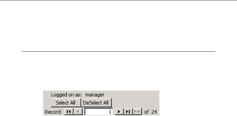
8E6 TECHNOLOGIES, ENTERPRISE REPORTER 3.0 USER’S GUIDE 167
CLIENT USER SECTION: CHAPTER 4 - USING THE CLIENT
a user could show an incredibly high page count and many
minutes, even though only one page was opened by that
user.
Select All, Deselect All buttons
The Select All and DeSelect All buttons display at the bottom
of the screen, beneath the username ID. These buttons affect
the checkboxes preceding the rows of records.
By default, check marks display in all checkboxes, which
means that all records will be included in the report view or in
the printed report.
To include only specified records in the report, de-select a
record by clicking in the checkbox to remove the check mark.
To de-select all items, click the DeSelect All button. To
include a record, click in the checkbox to add a check mark.
To include all records, click the Select All button.
Fig. 2:4-22 Select All and DeSelect All buttons

168 8E6 TECHNOLOGIES, ENTERPRISE REPORTER 3.0 USER’S GUIDE
CLIENT USER SECTION: CHAPTER 4 - USING THE CLIENT
Records
Beneath the Select All and DeSelect All buttons at the bottom
of the screen, the number of the record for the selected row
on the current screen displays at the Records field, along with
the total number of records in the current report. This indica-
tor helps you determine how long it will take to generate a
report view or to print a report. If there are many records, you
may wish to filter your results to reduce the time it will take to
process the report.
A record is selected by clicking in the grey box preceding the
checkbox in that row. This action displays an arrow in that
box, and the record number in the Record field.
You can navigate to another record by clicking any of the
arrow buttons. In the order in which they display on the
screen, clicking these buttons moves you to the first record,
the record prior to the selected record, the record following
the selected record, and the last record.

8E6 TECHNOLOGIES, ENTERPRISE REPORTER 3.0 USER’S GUIDE 169
CLIENT USER SECTION: CHAPTER 4 - USING THE CLIENT
Generate a Report
1. Select the report screen of your choice: Categories, IPs,
Users, Sites, Category Groups, or User Groups.
2. Specify the Date Scope: Month to Date, Monthly, Year to
Date, Daily, Yesterday, Today, Month to Yesterday, or Year
to Yesterday.
3. At the Reports (or Report Layout) field, select a report
type from the pull-down menu.
4. If necessary, do any of the following, in any order:
• To generate a report for a single record only, click the
designated filter button from the available column
choices.
• To sort records by a specified column, click the corre-
sponding Count column header.
• Click the Display button to open the Display Information
dialog box, and specify the manner in which you wish the
records to be sorted, from the available selections:
Category Count, IP Count, User Count, Object Count,
Page Count, Site Count, or Time Count. To include only
top records, enter the number of records and click the
Top button, or click All to include all records.
• If generating a page or object count report, the displayed
screen includes additional options. To include Informa-
tion columns for Category, User, IP, and Site, click in the
checkboxes. After making any selections, proceed on
that screen with the preceding steps for generating a
report.
5. This task can now be completed by clicking on one of the
following icons in the navigation bar: Save, View, Print, E-
mail, Export, or Record.

170 8E6 TECHNOLOGIES, ENTERPRISE REPORTER 3.0 USER’S GUIDE
CLIENT USER SECTION: CHAPTER 4 - USING THE CLIENT
• Click Save to save the report to a designated folder, in
the output format of your choice.
• Click View to view the report. If prompted, enter any view
specifications, and click Go or OK to view the report as
requested.
From the view window, you can print the report by select-
ing File > Print from the toolbar at the top of the window.
• Click Print to print the report without viewing it. If
prompted, enter any print specifications, and click Go or
OK to print the report as requested.
• Click E-mail to send the report to the designated
recipient(s), in the output format of your choice.
NOTE: If you are using Lotus Notes as your primary e-mail
client instead of Microsoft Outlook or Outlook Express, refer to
Appendix B for information on how to configure Lotus Notes to
work with the ER 3.0 Client.
• Click Export to export the raw report data to a desig-
nated folder, in the output format of your choice.
• Click Record to save custom report data. The custom
report can be generated and viewed, printed, e-mailed,
or saved in a selected file format.
Report Formats
Reports in the standard report format are available for all
main report groups (Categories, IPs, Users, Sites, Category
Groups, and User Groups), and for Page Count and Object
Count reports. Pie chart and bar chart formats are available
for Categories, Category Groups, and User Groups reports.
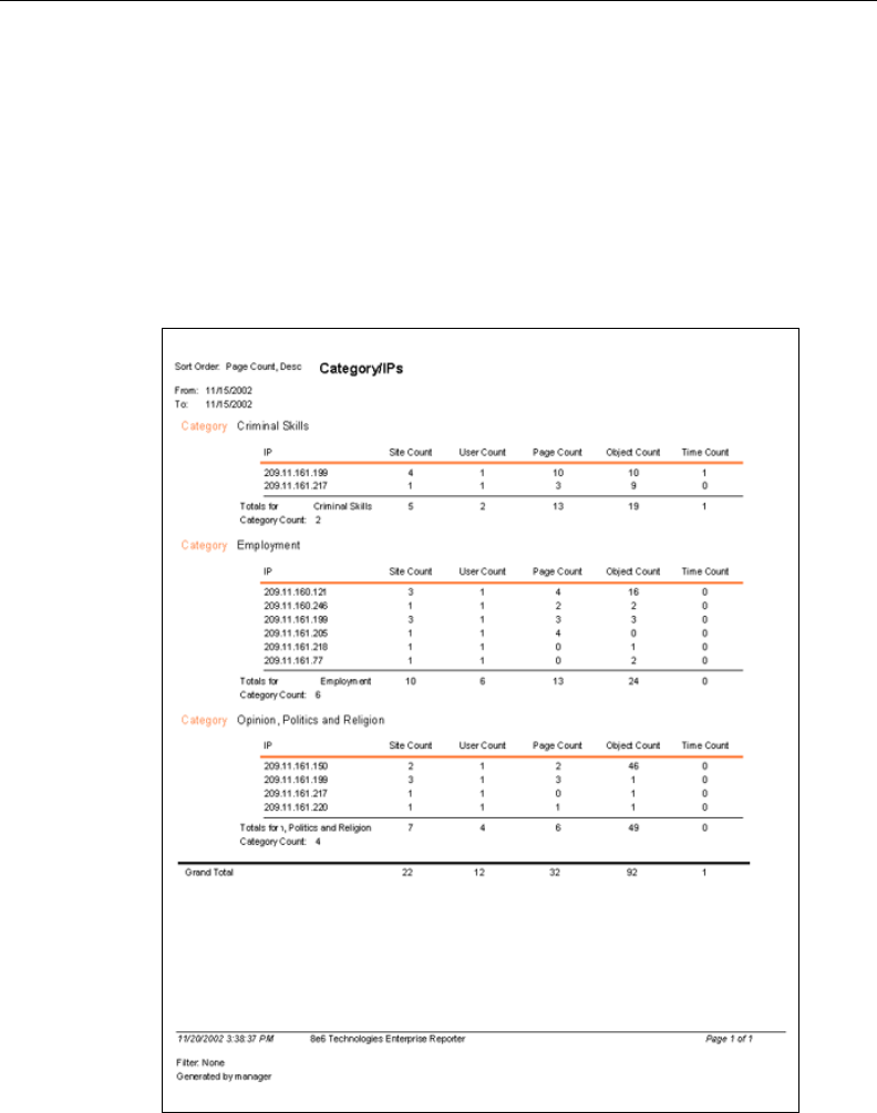
8E6 TECHNOLOGIES, ENTERPRISE REPORTER 3.0 USER’S GUIDE 171
CLIENT USER SECTION: CHAPTER 4 - USING THE CLIENT
Standard report
Standard reports include text only, arranged in columns and
rows. The header displays the name of the report, the Sort
Order, and the date range. The body of the report includes
data grouped into sections, columns, and rows, according to
your specifications. Totals for each section display, followed
by a Grand Total at the end of the report. The footer displays
Fig. 2:4-23 Standard report format
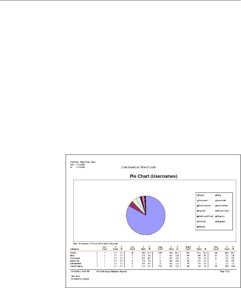
172 8E6 TECHNOLOGIES, ENTERPRISE REPORTER 3.0 USER’S GUIDE
CLIENT USER SECTION: CHAPTER 4 - USING THE CLIENT
Fig. 2:4-24 Pie Chart report format
the date and time the report was generated, the page number
and range of pages in the report, selected Filter settings, and
username of the user login ID (Generated by).
Pie Chart report
Pie charts feature color-coded, circular diagrams broken into
sections, depicting the quantity of items in each category or
group. The top of the report displays the name of the report,
the Sort Order, and the date range. The body of the report
includes the pie chart and color key. Beneath this chart is a
text report showing the type of sort selected, and columns of
figures and percentages. The footer displays the date and
time the report was generated, the page number and range of
pages in the report, selected Filter settings, and username of
the user login ID (Generated by).
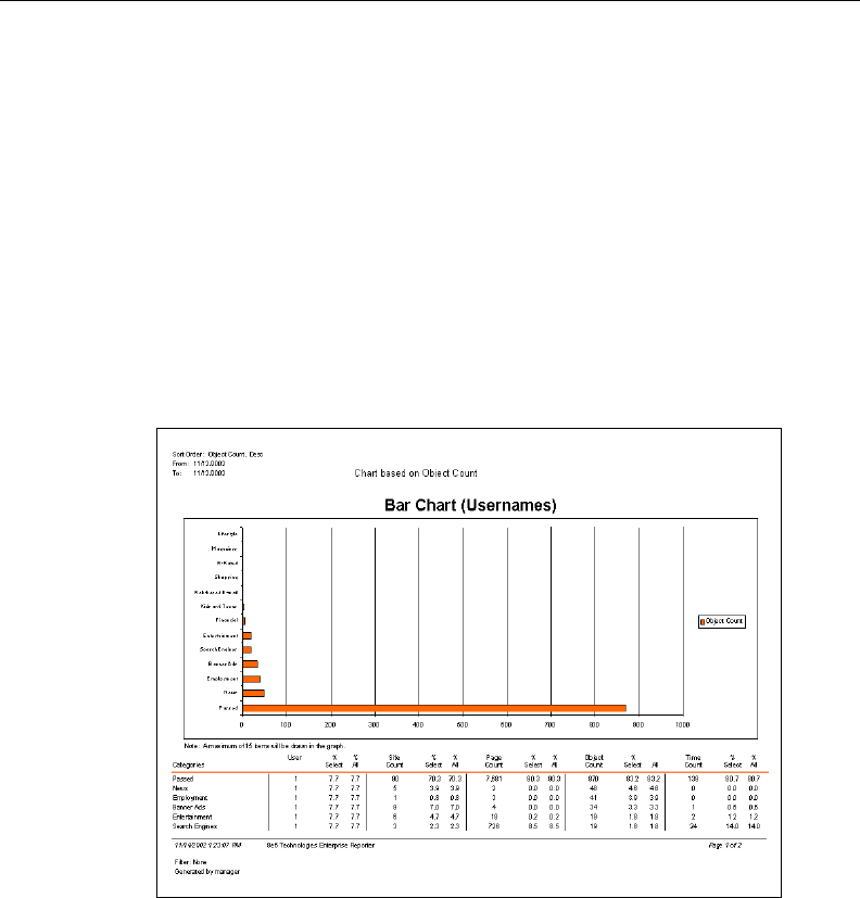
8E6 TECHNOLOGIES, ENTERPRISE REPORTER 3.0 USER’S GUIDE 173
CLIENT USER SECTION: CHAPTER 4 - USING THE CLIENT
Bar Chart report
Bar charts feature color-coded blocks that represent the
quantity of items in each category or group. The top of the
report displays the name of the report, the Sort Order, and the
date range. The body of the report includes the bar chart and
color key. Beneath this chart is a text report showing the type
of sort selected, and columns of figures and percentages.
The footer displays the date and time the report was gener-
ated, the page number and range of pages in the report,
selected Filter settings, and username of the user login ID
(Generated by).
Fig. 2:4-25 Bar Chart report format
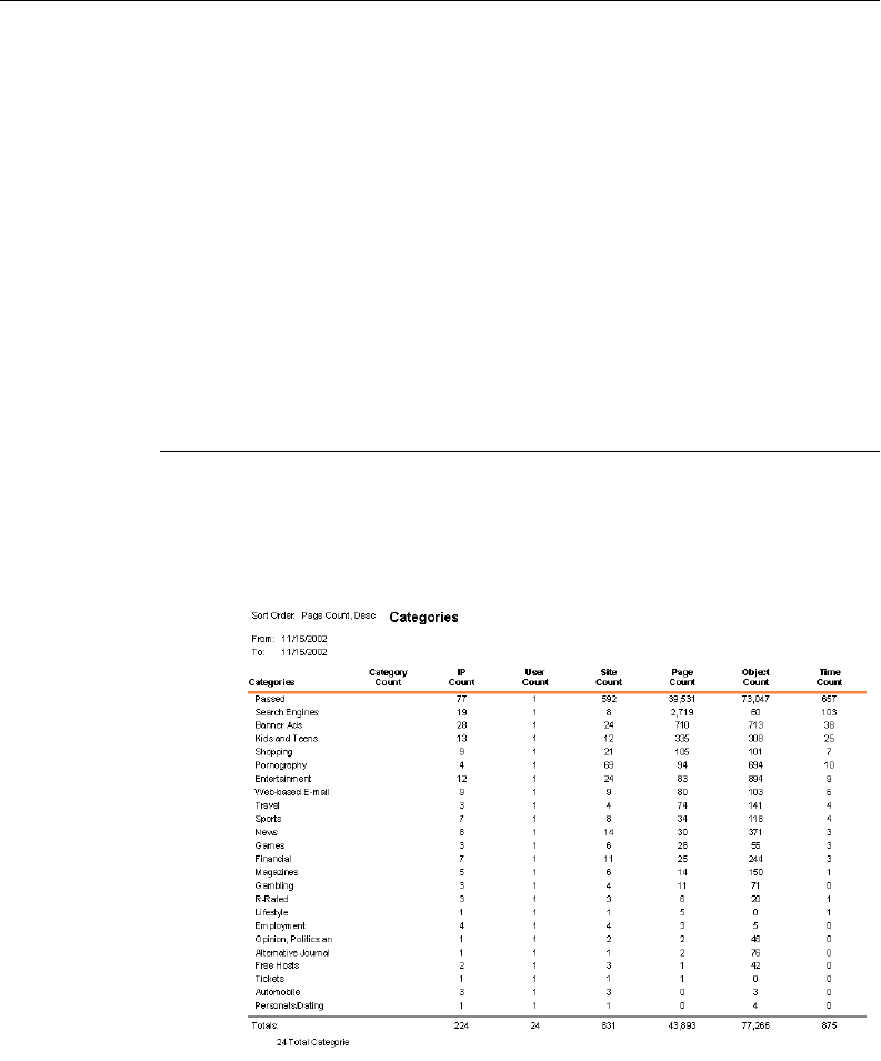
174 8E6 TECHNOLOGIES, ENTERPRISE REPORTER 3.0 USER’S GUIDE
CLIENT USER SECTION: CHAPTER 5 - REPORTS
Chapter 5: Reports
Due to the variations of reports that can be generated by the
ER 3.0, only the basic reports from each report group will be
described.
Categories Reports
Reports in this group are used for analyzing activity in catego-
ries set up to be monitored.
Categories
The Categories report shows an itemized list of all categories
with totals in the Count columns. The sum of all Totals dis-
plays at the end of the report.
Fig. 2:5-1 Categories report
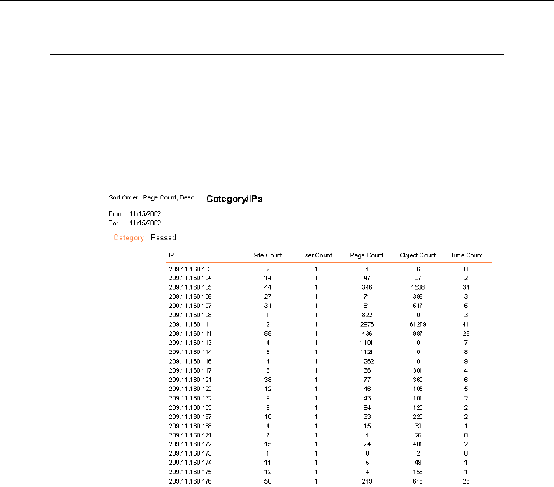
8E6 TECHNOLOGIES, ENTERPRISE REPORTER 3.0 USER’S GUIDE 175
CLIENT USER SECTION: CHAPTER 5 - REPORTS
Category/IPs
The Category/IPs report is broken out by category, with each
category showing an itemized list of IP adresses. Count
column Totals are included for each IP address in the list.
Totals display for each Category, and the Grand Total for all
categories displays at the end of the report.
Fig. 2:5-2 Category/IPs report
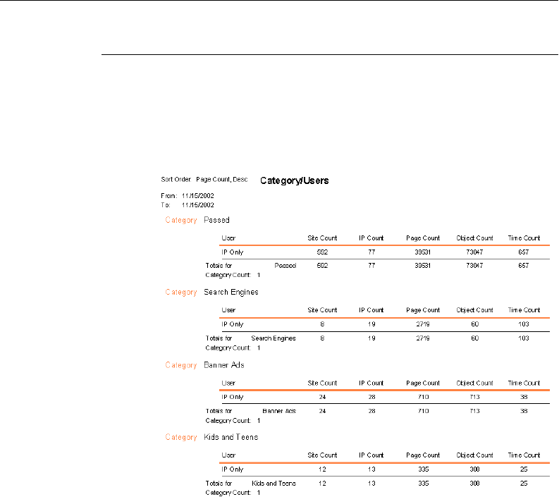
176 8E6 TECHNOLOGIES, ENTERPRISE REPORTER 3.0 USER’S GUIDE
CLIENT USER SECTION: CHAPTER 5 - REPORTS
Category/Users
The Category/Users report is broken out by category, with
each category showing Count column Totals for all users.
Category Count Totals display for each category, and the
Grand Total for all categories displays at the end of the report.
Fig. 2:5-3 Category/Users report
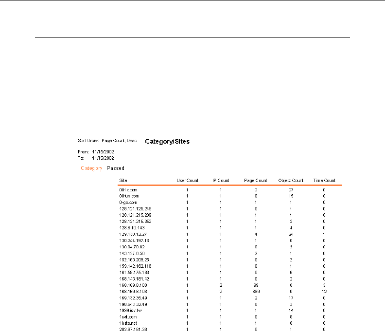
8E6 TECHNOLOGIES, ENTERPRISE REPORTER 3.0 USER’S GUIDE 177
CLIENT USER SECTION: CHAPTER 5 - REPORTS
Category/Sites
The Category/Sites report is broken out by category, with
each category showing an itemized list of visited sites. Count
column Totals are included for each site in the list. Totals
display for each Category, and the Grand Total for all catego-
ries displays at the end of the report.
Fig. 2:5-4 Category/Sites report
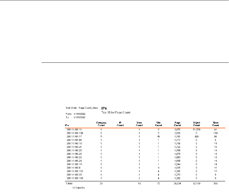
178 8E6 TECHNOLOGIES, ENTERPRISE REPORTER 3.0 USER’S GUIDE
CLIENT USER SECTION: CHAPTER 5 - REPORTS
IPs Reports
Reports in this group are used for analyzing user activity by
the IP address of the user.
IPs
The IPs report shows an itemized list of all IP addresses with
totals in the Count columns. The sum of all Totals displays at
the end of the report.
Fig. 2:5-5 IPs report
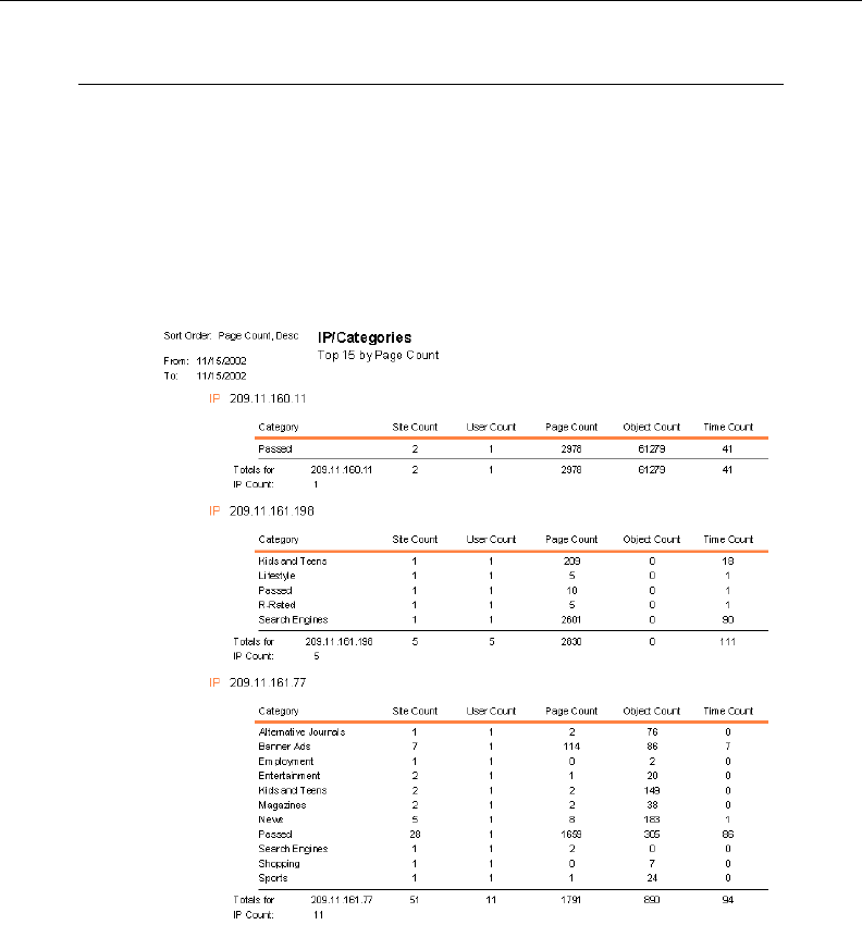
8E6 TECHNOLOGIES, ENTERPRISE REPORTER 3.0 USER’S GUIDE 179
CLIENT USER SECTION: CHAPTER 5 - REPORTS
IP/Categories
The IP/Categories report is broken out by IP address, with
each IP address showing an itemized list of categories visited
by that user’s machine. Count column Totals are included for
each category in the list. Totals display for each IP address,
and the Grand Total for all IP addresses displays at the end of
the report.
Fig. 2:5-6 IP/Categories report
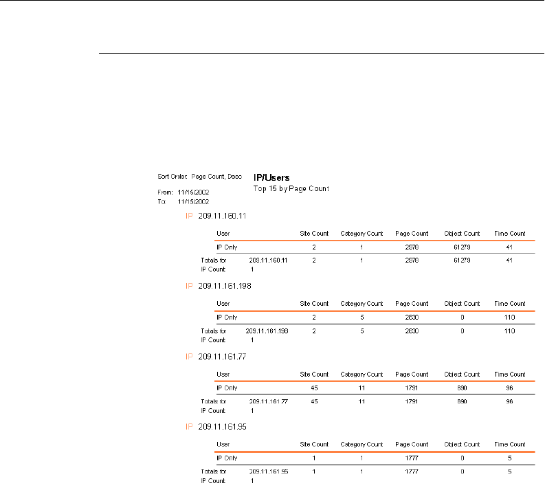
180 8E6 TECHNOLOGIES, ENTERPRISE REPORTER 3.0 USER’S GUIDE
CLIENT USER SECTION: CHAPTER 5 - REPORTS
IP/Users
The IP/Users report is broken out by IP address, with each IP
address showing Count column Totals. IP Count Totals
display for each IP address, and the Grand Total for all IP
addresses displays at the end of the report.
Fig. 2:5-7 IP/Users report
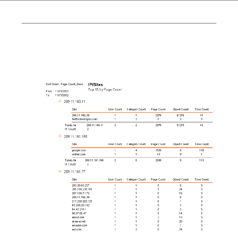
8E6 TECHNOLOGIES, ENTERPRISE REPORTER 3.0 USER’S GUIDE 181
CLIENT USER SECTION: CHAPTER 5 - REPORTS
IP/Sites
The IP/Sites report is broken out by IP address, with each IP
address showing an itemized list of visited sites. Count
column Totals are included for each site in the list. IP Count
Totals display for each IP address, and the Grand Total for all
IP addresses displays at the end of the report.
Fig. 2:5-8 IP/Sites report
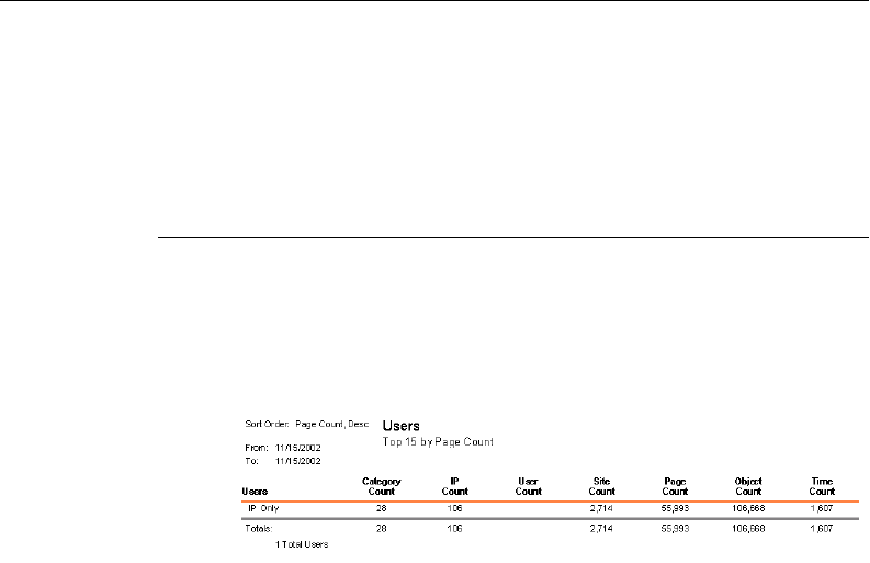
182 8E6 TECHNOLOGIES, ENTERPRISE REPORTER 3.0 USER’S GUIDE
CLIENT USER SECTION: CHAPTER 5 - REPORTS
Users Reports
Reports in this group are used for analyzing user activity by
user.
Users
The Users report shows totals for all users in the Count
columns. The sum of all Totals displays at the end of the
report.
Fig. 2:5-9 Users report
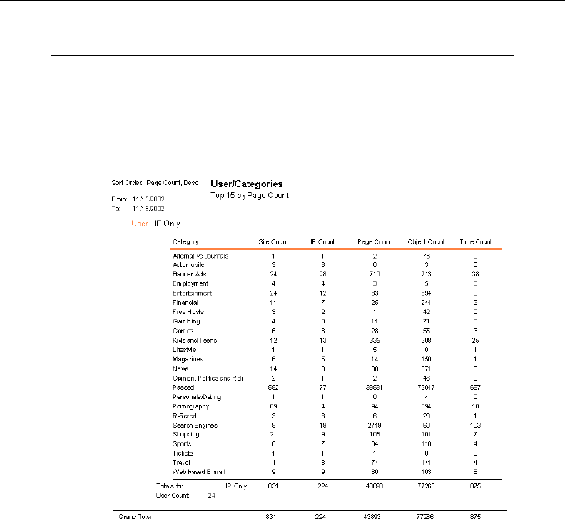
8E6 TECHNOLOGIES, ENTERPRISE REPORTER 3.0 USER’S GUIDE 183
CLIENT USER SECTION: CHAPTER 5 - REPORTS
User/Categories
The User/Categories report shows an itemized list of catego-
ries visited by all users. Count column Totals are included for
each category in the list. User Count Totals and the Grand
Total display at the end of the report.
Fig. 2:5-10 User/Categories report
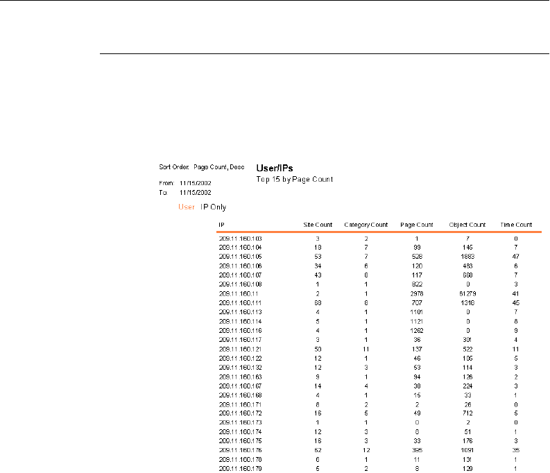
184 8E6 TECHNOLOGIES, ENTERPRISE REPORTER 3.0 USER’S GUIDE
CLIENT USER SECTION: CHAPTER 5 - REPORTS
User/IPs
The Users/IPs report is broken out by user, with each user
showing Count column Totals. User Count Totals and the
Grand Total display at the end of the report.
Fig. 2:5-11 User/IPs report
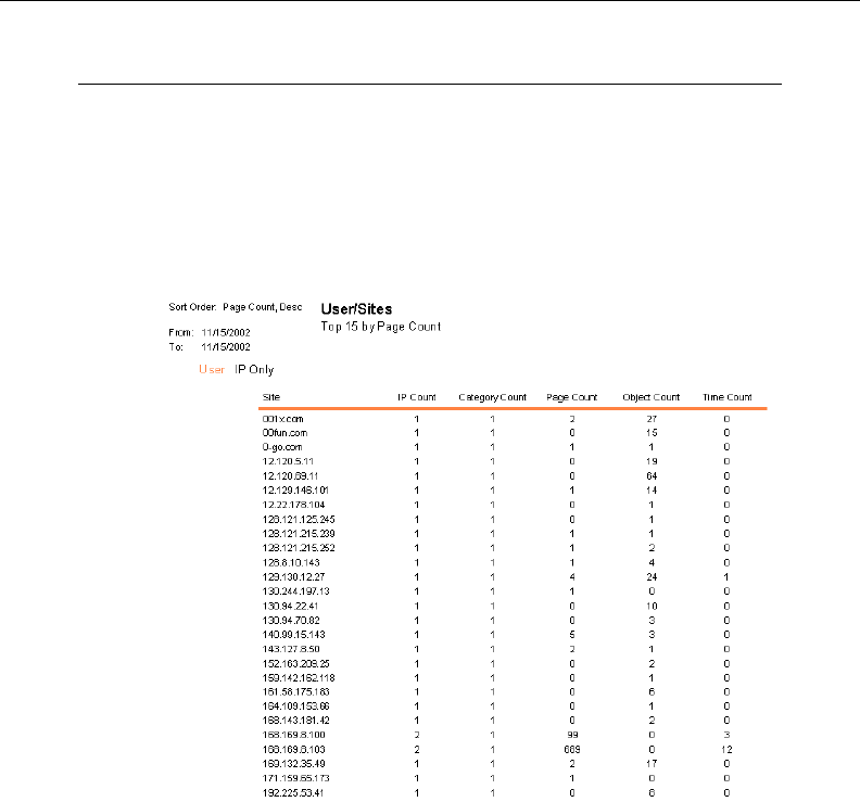
8E6 TECHNOLOGIES, ENTERPRISE REPORTER 3.0 USER’S GUIDE 185
CLIENT USER SECTION: CHAPTER 5 - REPORTS
User/Sites
The User/Sites report is broken out by user, with each user
showing an itemized list of visited sites. Count column Totals
are included for each site in the list. User Count Totals display
for each user, and the Grand Total for all users displays at the
end of the report.
Fig. 2:5-12 User/Sites report
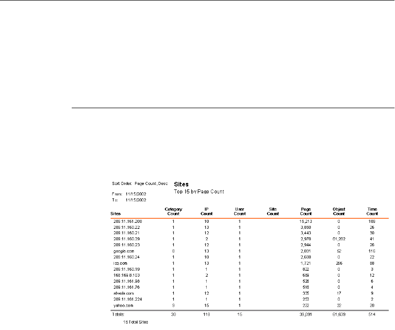
186 8E6 TECHNOLOGIES, ENTERPRISE REPORTER 3.0 USER’S GUIDE
CLIENT USER SECTION: CHAPTER 5 - REPORTS
Sites Reports
Reports in this group are used for analyzing user activity by
sites visited.
Sites
The Sites report shows an itemized list of all sites visited with
totals in the Count columns. The sum of all Totals displays at
the end of the report.
Fig. 2:5-13 Sites report
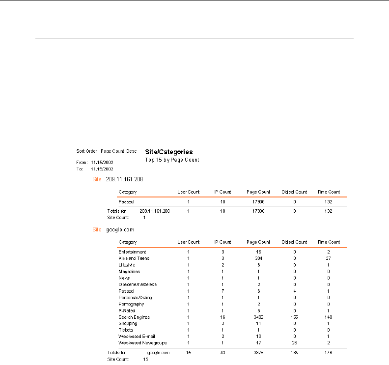
8E6 TECHNOLOGIES, ENTERPRISE REPORTER 3.0 USER’S GUIDE 187
CLIENT USER SECTION: CHAPTER 5 - REPORTS
Site/Categories
The Site/Categories report is broken out by site address, with
each site address showing an itemized list of categories in
which that site visit can be classified. Count column Totals are
included for each site in the list. Site Count Totals display for
each site, and the Grand Total for all sites displays at the end
of the report.
Fig. 2:5-14 Site/Categories report
188 8E6 TECHNOLOGIES, ENTERPRISE REPORTER 3.0 USER’S GUIDE
CLIENT USER SECTION: CHAPTER 5 - REPORTS
Site/IPs
The Site/IPs report is broken out by site address, with each
site address showing an itemized list of IP addresses of
visitors. Count column Totals are included for each IP ad-
dress in the list. Site Count Totals display for each site ad-
dress, and the Grand Total for all site addresses displays at
the end of the report.
Fig. 2:5-15 Site/IPs report
8E6 TECHNOLOGIES, ENTERPRISE REPORTER 3.0 USER’S GUIDE 189
CLIENT USER SECTION: CHAPTER 5 - REPORTS
Site/Users
The Site/Users report is broken out by site address, with each
site address showing Count column Totals for all users who
visited that site. Site Count Totals display for each site, and
the Grand Total for all sites displays at the end of the report.
Fig. 2:5-16 Site/Users report
190 8E6 TECHNOLOGIES, ENTERPRISE REPORTER 3.0 USER’S GUIDE
CLIENT USER SECTION: CHAPTER 5 - REPORTS
Category Groups Report
Category Group reports are only available if category groups
are set up via the Category Groupings Settings option from
the main menu. These reports give you the flexibility to view
user-defined criteria in the format of your choice, and to
compare activity by user-defined groups. Reports can be
generated in standard, pie chart, or bar chart formats.
User Groups Report
User Groups reports are only available if user groups are set
up via the User Groupings Settings option from the main
menu. These reports are used for analyzing the activity of
users set up in a user-defined group, and for comparing
activity by user groups. Reports can be generated in stan-
dard, pie chart, or bar chart formats.
Fig. 2:5-17 User Groups report
8E6 TECHNOLOGIES, ENTERPRISE REPORTER 3.0 USER’S GUIDE 191
CLIENT USER SECTION: CHAPTER 5 - REPORTS
Page/Object Reports
Page/Object reports are only available from page/object
count report screens, or from find pages/objects report
screens.
Page/object count screens are accessible from any main
report screen by either clicking the Search button and per-
forming a search for specified criteria, or by clicking the down
arrow to the right of the Page Count or Object Count columns
for a specified record.
Find page/object screens are available by clicking the Spe-
cific Search button in the main menu.
TIP: If searching for pages, if the date range that was specified
is outside the scope of live data currently stored on the Server, a
warning message displays to inform you that if you wish to
proceed, the report will take a longer amount of time to generate.
Fig. 2:5-18 Objects report screen
192 8E6 TECHNOLOGIES, ENTERPRISE REPORTER 3.0 USER’S GUIDE
CLIENT USER SECTION: CHAPTER 5 - REPORTS
Fig. 2:5-19 Objects report
If searching for objects, if the date range that was specified
includes both live and archive data currently stored on the Server,
a warning message displays to inform you that if you wish to
proceed, only the objects that exist on the Server will display. If
objects no longer exist on the Server, a message displays to
inform you that these objects no longer exist.
In the top left portion of these screens, checkboxes for
Category Information, User Information, IP Information, and
Site Information can be selected. By selecting any of these
items, the corresponding column displays on the report
screen.
After selecting the Report Layout, and clicking View or
Print, the report is generated with the Date and URL, along
with any specified reporting elements.
As with all other reports, in addition to the View and Print
options, the following other options are available for Page/
Object reports: Save, E-mail, Export, and Record.

8E6 TECHNOLOGIES, ENTERPRISE REPORTER 3.0 USER’S GUIDE 193
TECHNICAL SUPPORT / PRODUCT WARRANTIES SECTION
TECHNICAL SUPPORT / PRODUCT
WARRANTIES SECTION
Technical Support
For technical support, visit 8e6 Technologies’s Technical
Support Web page at http://www.8e6technologies.com/
techsupport/index.html, or contact us by phone, by e-mail,
or in writing.
Hours
Regular office hours are from Monday through Friday, 8 a.m.
to 5 p.m. PST.
After hours support is available for emergency issues only.
Requests for assistance are routed to a senior-level techni-
cian through our forwarding service.
Contact Information
Domestic (United States)
1. Call 1-888-786-7999
2. Select option 2
International
1. Call +1-714-282-6111
2. Select option 2

194 8E6 TECHNOLOGIES, ENTERPRISE REPORTER 3.0 USER’S GUIDE
TECHNICAL SUPPORT / PRODUCT WARRANTIES SECTION
E-Mail
For non-emergency assistance, e-mail us at
support@8e6technologies.com
Address
8e6 Technologies
828 W. Taft Avenue
Orange, CA 92865
Support Procedures
When you contact our technical support department:
• You will be greeted by a technical professional who will
request the details of the problem and attempt to resolve
the issue directly.
• If your issue needs to be escalated, you will be given a
ticket number for reference, and a senior-level technician
will contact you to resolve the issue.
• If your issue requires immediate attention, such as your
network traffic being affected or all blocked sites being
passed, you will be contacted by a senior-level technician
within one hour.
• Your trouble ticket will not be closed until your permission is
confirmed.

8E6 TECHNOLOGIES, ENTERPRISE REPORTER 3.0 USER’S GUIDE 195
TECHNICAL SUPPORT / PRODUCT WARRANTIES SECTION
Product Warranties
Standard Warranty
8e6 Technologies warrants the medium on which the 8e6
product is provided to be free from defects in material and
workmanship under normal use for period of one year (the
“Warranty Period”) from the date of delivery. 8e6 Technolo-
gies’ entire liability and customer’s exclusive remedy if the
medium is defective shall be the replacement of the hardware
equipment or software provided by 8e6 Technologies.
8e6 Technologies warrants that the 8e6 product(s) do(es) not
infringe on any third party copyrights or patents. This warranty
shall not apply to the extent that infringement is based on any
misuse or modification of the hardware equipment or soft-
ware provided. This warranty does not apply if the infringe-
ment is based in whole or in part on the customer’s modifica-
tion of the hardware equipment or software.
8e6 Technologies specifically disclaims all express warranties
except those made herein and all implied warranties; includ-
ing without limitation, the implied warranties of merchantabil-
ity and fitness for a particular purpose. Without limitation, 8e6
Technologies specifically disclaims any warranty related to
the performance(s) of the 8e6 product(s). Warranty service
will be performed during 8e6 Technologies’ regular business
hours at 8e6 Technologies’ facility.

196 8E6 TECHNOLOGIES, ENTERPRISE REPORTER 3.0 USER’S GUIDE
TECHNICAL SUPPORT / PRODUCT WARRANTIES SECTION
Technical Support and Service
8e6 Technologies will provide initial installation support and
technical support for up to 90 days following installation. 8e6
Technologies provides after-hour emergency support to 8e6
server customers. An after hours technician can be reached
by voice line.
Technical support information:
Online: http://www.8e6.com/techsupport/
Toll Free: 888-786-7999, press 2
Telephone: 1+714-282-6111, press 2
E-mail: support@8e6technologies.com
Have the following information ready before calling technical
support:
Product Description: _______________________________
Purchase Date: ___________________________________
Extended warranty purchased: _______________________
Plan # __________________________________________
Reseller or Distributor contact: _______________________
Customer contact: _________________________________

8E6 TECHNOLOGIES, ENTERPRISE REPORTER 3.0 USER’S GUIDE 197
TECHNICAL SUPPORT / PRODUCT WARRANTIES SECTION
Extended Warranty (optional)
The extended warranty applies to hardware and software of
the product(s) except any misuse or modification of the
product(s), or product(s) located outside of the United States.
The extended warranty does not include new product up-
grades. Hardware parts will be furnished as necessary to
maintain the proper operational condition of the product(s). If
parts are discontinued from production during the Warranty
Period, immediate replacement product(s) or hardware parts
will be available for exchange with defective parts from 8e6
Technologies’ local reseller or distributor.
Extended Technical Support and Service
Extended technical support is available to customers under a
Technical Support Agreement. Contact 8e6 Technologies
during normal business hours, 8 a.m. to 5 p.m. PST, at (888)
786-7999, or if outside the United States, call 1+(714) 282-
6111.

198 8E6 TECHNOLOGIES, ENTERPRISE REPORTER 3.0 USER’S GUIDE
APPENDICES SECTION: APPENDIX A
APPENDICES SECTION
Appendix A
Scheduled Task Wizard
If you wish to run a report at a specified time, if the report was
not set up via the Automatic Report Setup option during the
installation of the Client, you need to add a scheduled task on
your machine. This setup must be performed in addition to
scheduling an event via the Event Schedule option in the
Settings menu.
NOTE: See Event Schedule in Chapter 3: Customizing the
Client from the Client User Section for information about setting
up the Client to run at a specified time.
Steps for Scheduling a Task
Follow these steps to set up a report to run at a scheduled
time:
1. From the taskbar of your machine, go to Start > Settings >
Control Panel to open the Control Panel window:
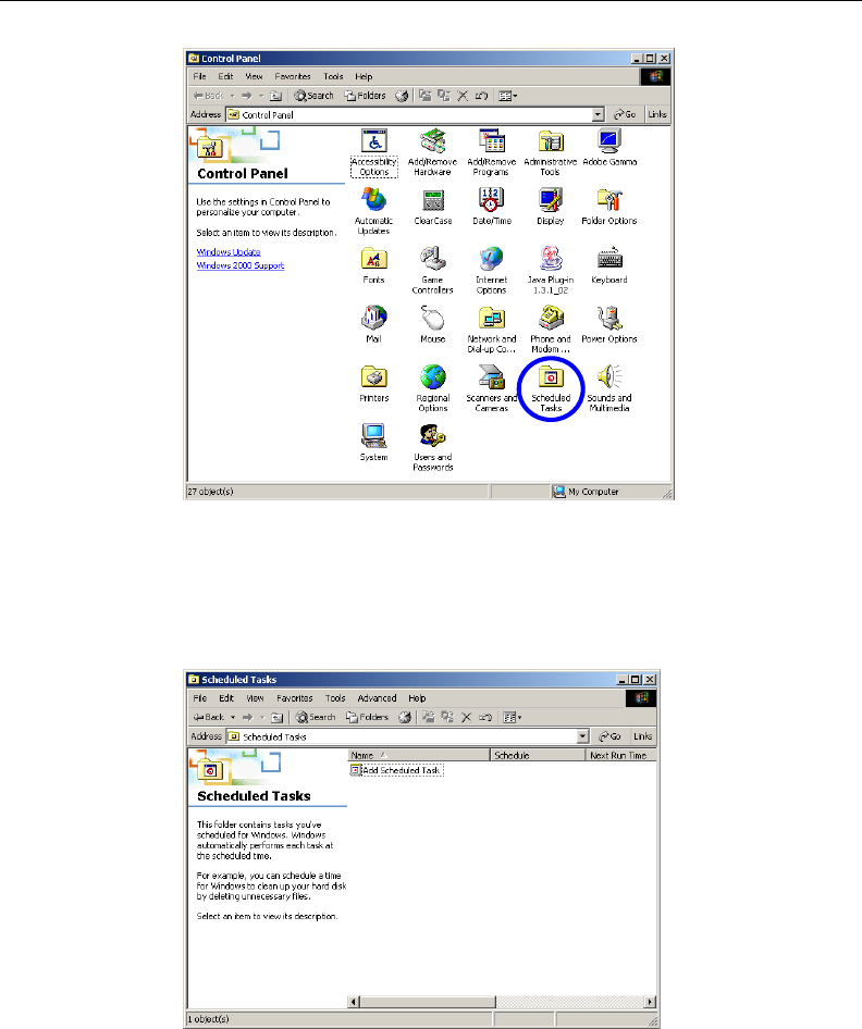
8E6 TECHNOLOGIES, ENTERPRISE REPORTER 3.0 USER’S GUIDE 199
APPENDICES SECTION: APPENDIX A
2. Choose Scheduled Tasks to open the Scheduled Tasks
window:
Fig. 4:1-1 Control Panel window
Fig. 4:1-2 Scheduled Tasks window
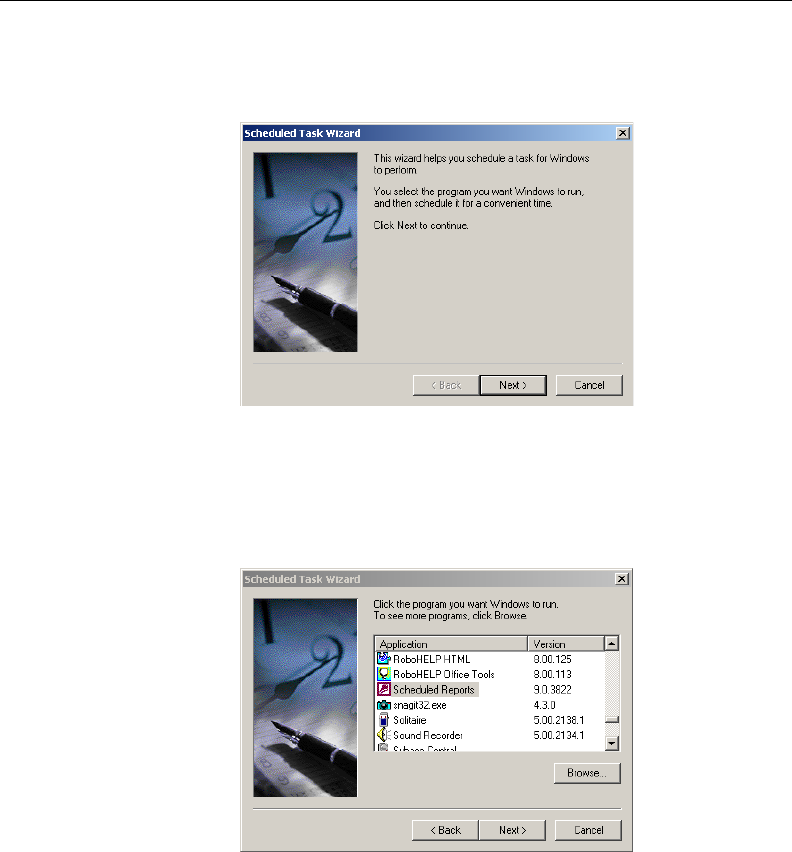
200 8E6 TECHNOLOGIES, ENTERPRISE REPORTER 3.0 USER’S GUIDE
APPENDICES SECTION: APPENDIX A
3. Click Add Scheduled Task to launch the Scheduled Task
Wizard:
4. Click Next to display the list box showing available applica-
tions that can be run:
5. Choose Scheduled Reports, and then click Next to
specify criteria for the task:
Fig. 4:1-3 Scheduled Task Wizard, 1st frame
Fig. 4:1-4 Scheduled Task Wizard, 2nd frame
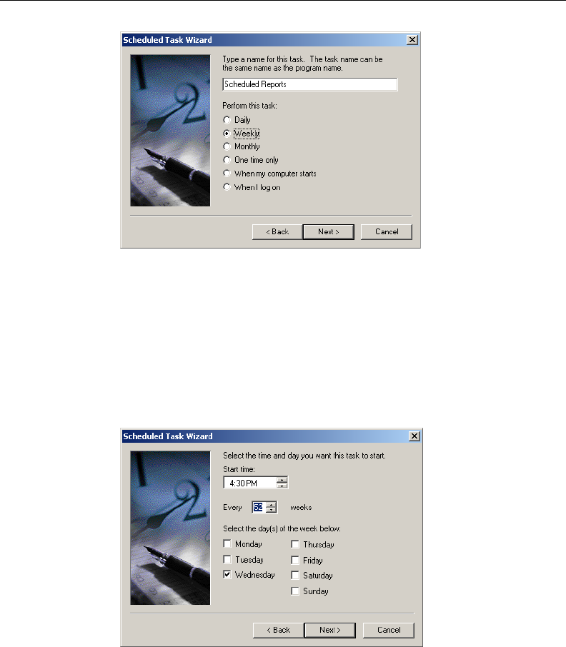
8E6 TECHNOLOGIES, ENTERPRISE REPORTER 3.0 USER’S GUIDE 201
APPENDICES SECTION: APPENDIX A
6. Accept the name of the task that displays in the text box, or
enter a different name. Indicate when the task should be
performed by clicking the radio button corresponding to the
option for Daily, Weekly, or Monthly. When Next is
clicked, the Wizard selections will differ depending on the
time interval specified for performing the task:
7. Specify criteria regarding the time the task will be per-
formed, and then click Next to display text boxes for user
criteria:
Fig. 4:1-5 Scheduled Task Wizard, 3rd frame
Fig. 4:1-6 Scheduled Task Wizard, 4th frame
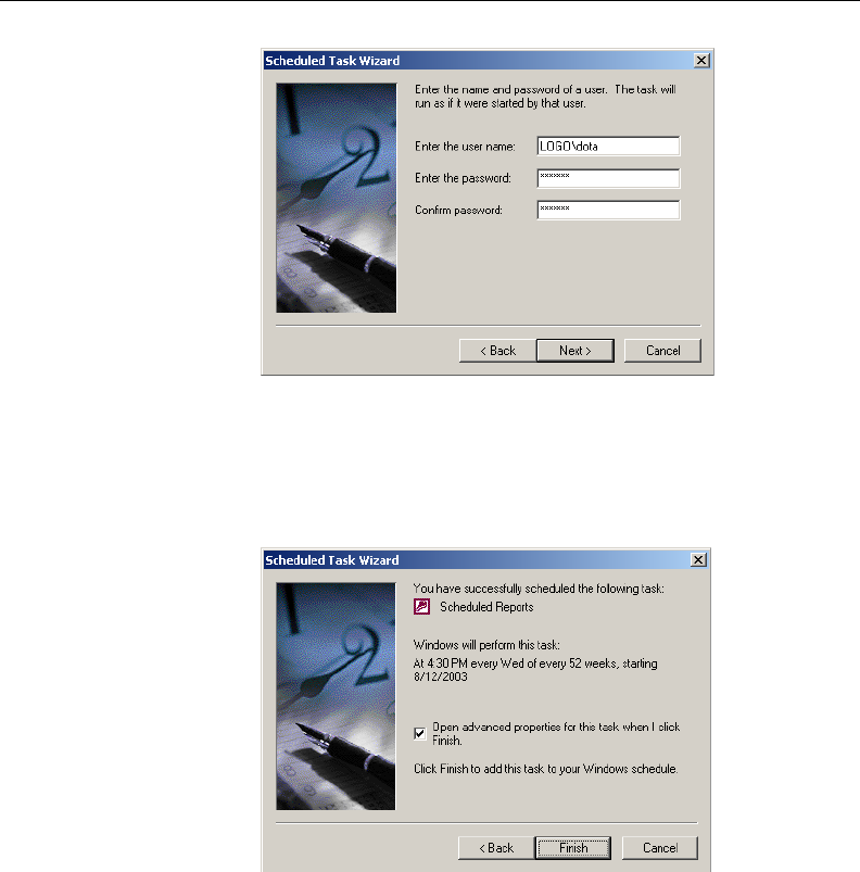
202 8E6 TECHNOLOGIES, ENTERPRISE REPORTER 3.0 USER’S GUIDE
APPENDICES SECTION: APPENDIX A
8. If necessary, modify the user name that displays. Enter the
password used when logging on your machine, and then
click Next:
9. If you are scheduling more than one report to run at the
same time, click in the advanced properties checkbox.
Click Finish to close the Wizard.
a. If you clicked in the checkbox for advanced properties,
upon clicking Finish the dialog box for the scheduled
task opens:
Fig. 4:1-7 Scheduled Task Wizard, 5th frame
Fig. 4:1-8 Scheduled Task Wizard, 6th frame
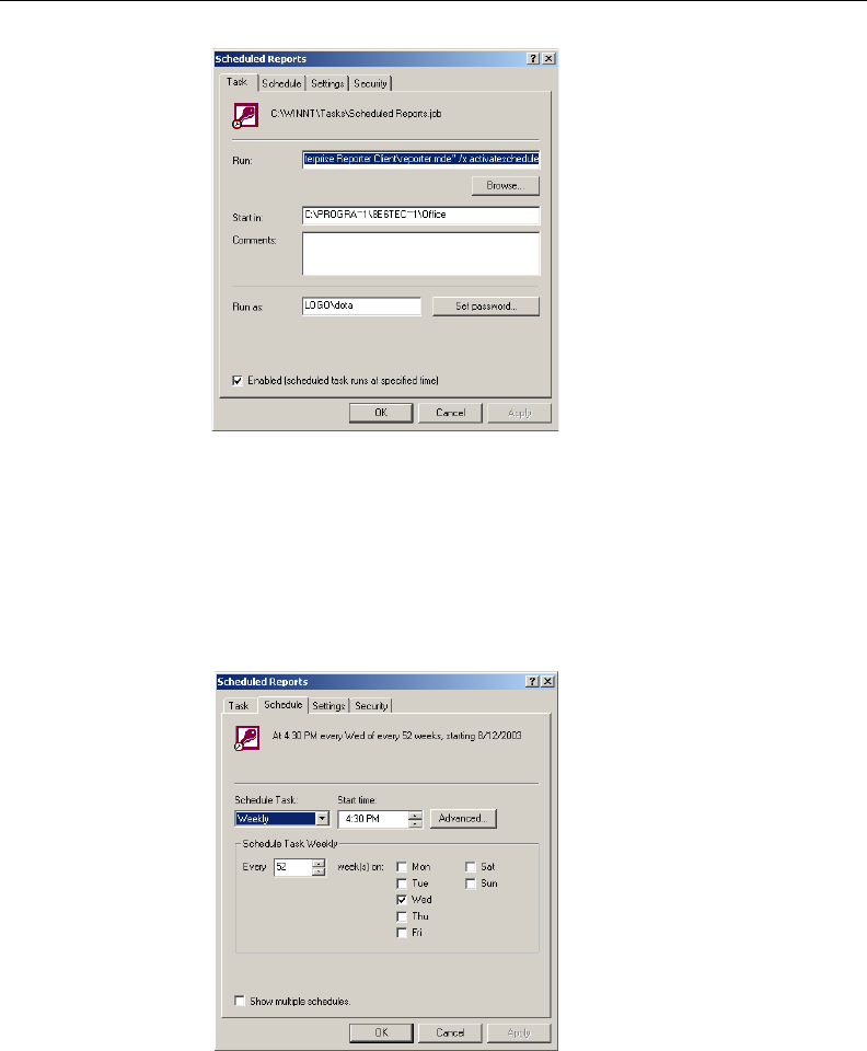
8E6 TECHNOLOGIES, ENTERPRISE REPORTER 3.0 USER’S GUIDE 203
APPENDICES SECTION: APPENDIX A
b. If “deactivated” displays in the Run text box, change the
text to “activated”.
c. If necessary, click the Schedule tab to modify schedule
criteria:
Fig. 4:1-9 Dialog box, Task tab
Fig. 4:1-10 Dialog box, Schedule tab
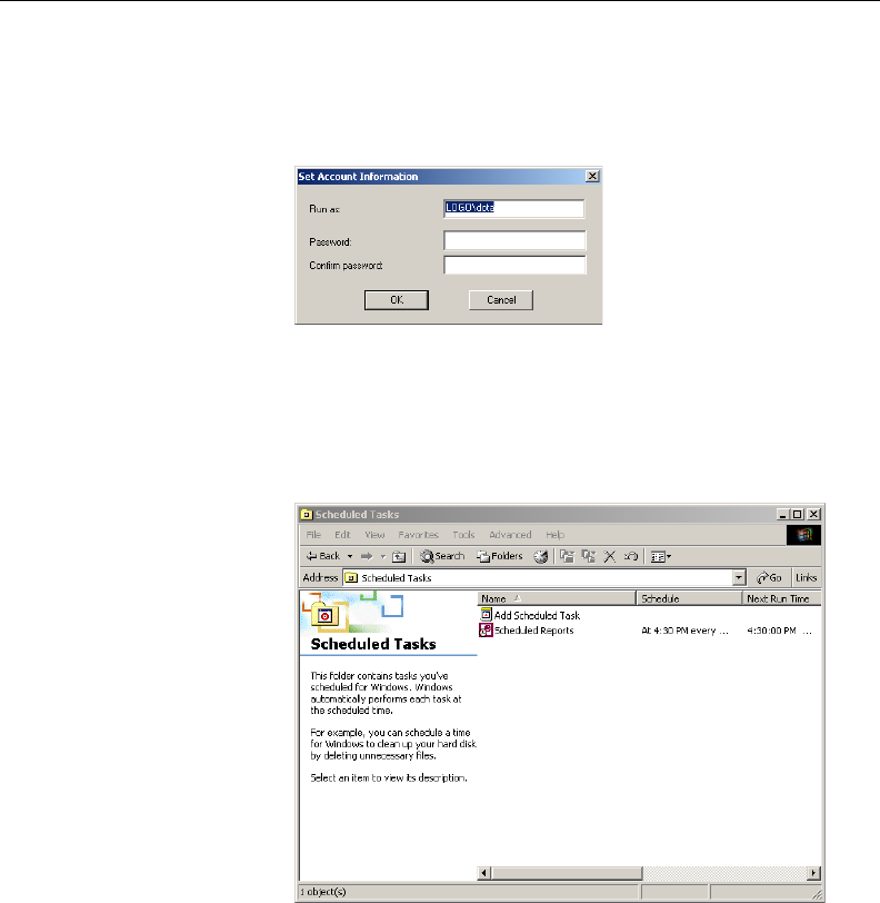
204 8E6 TECHNOLOGIES, ENTERPRISE REPORTER 3.0 USER’S GUIDE
APPENDICES SECTION: APPENDIX A
d. If entries were made in either tab, click Apply. If edits
were made on the Task tab, the Set Account Information
dialog box opens:
e. Enter the password twice, and then click OK to close the
Set Account Information dialog box and to display the
Scheduled Tasks window:
10. The scheduled task can be modified at any time via the
Scheduled Tasks window. Click the icon for the scheduled
task to open the dialog box for the task, and make the
necessary edits.
The task can be deleted by selecting the icon for the task
from this window, and then deleting the icon.
Fig. 4:1-11 Set Account Info box
Fig. 4:1-12 Scheduled Tasks window

8E6 TECHNOLOGIES, ENTERPRISE REPORTER 3.0 USER’S GUIDE 205
APPENDICES SECTION: APPENDIX B
Appendix B
Lotus Notes Configuration
This appendix provides information on configuring the ER 3.0
client to use Lotus Notes (4.5 and above) in a Microsoft
Windows environment in which Lotus Domino is the primary
e-mail server.
Making these configurations ensures that e-mail reports sent
from the ER 3.0 Client are transported via the MAPI client in
Outlook Express directly to the IP Address of the Lotus
Domino e-mail server. This setup avoids any delays or “hung”
reports that may occur if settings point to the Lotus Notes
client, since Lotus Notes utilizes the MAPI .DLL differently
than mail clients native to the Windows OS.
NOTE: Versions of Lotus Notes prior to 4.5 do not contain
the necessary MAPI transport .DLL.
Steps for Former MS Outlook / Express Users
Follow these steps if Microsoft Outlook or Outlook Express
was the primary e-mail client used on your system.
1. Delete any current e-mail accounts residing in Outlook or
Outlook Express.
2. If Outlook is currently installed with your Microsoft Office
system, uninstall Outlook—but not Outlook Express.
206 8E6 TECHNOLOGIES, ENTERPRISE REPORTER 3.0 USER’S GUIDE
APPENDICES SECTION: APPENDIX B
Steps for Installing and Configuring Lotus Notes
Step 1: Install Lotus Notes
Install and configure Lotus Notes to connect to your network’s
Lotus Domino server.
NOTE: Check with your System Administrator if you are
unsure about your settings.
Step 2: Configure Microsoft Mail Client
Make the following configurations for the Microsoft Mail Client
from the control panel:
1. When running the Internet Connection and Internet Ex-
plorer e-mail client wizard, be sure the e-mail address is set
to the “Internet address” of your Lotus Notes account.
NOTE: If this account has not yet been set up in Lotus
Domino, create it now, and then run the e-mail client wizard.
2. When the e-mail account wizard requests the server
address, use the IP Address only—not the Lotus Name—
of your Lotus Domino server.
TIP: These settings also can be generated directly by using
the “mail” settings in the Windows control panel. Again, any
previous non-Lotus Notes accounts must be deleted.
Step 3: Verify Internet Explorer Settings
1. Open Internet Explorer.
2. Go to Tools > Internet Options > Programs tab.
3. Check your “E-mail” and “Newsgroups” settings to make
sure they are set to “Outlook Express”—not Lotus Notes.

8E6 TECHNOLOGIES, ENTERPRISE REPORTER 3.0 USER’S GUIDE 207
INDEX
INDEX
A
add/edit/delete administrators 23
Add/Edit/Delete Administrators screen 29
Admin Details button 89, 95, 99
administrator
e-mail contact setup 47
log in to Server 23
Administrator Details 95
Administrator GUI 25
alert box, terminology 16
archive
data setup on Server 67
terminology 68
arrow, terminology 16
automatic reporting 87
B
Back icon 147
back up data
internal on demand backup 44
to remote server 45
backup
procedures 42
Backup screen 41
Bar Chart report 173
Box Mode screen 27
button, terminology 16
C
Categories icon 147
Categories reports 174
Category Descriptions button 113
category group
add additional groups 119
how to add 117

208 8E6 TECHNOLOGIES, ENTERPRISE REPORTER 3.0 USER’S GUIDE
INDEX
Category Groupings button 116
Category Groups icon 148
Category Groups report 190
Category/IPs report 175
Category/Sites report 177
Category/Users report 176
change database password 66
charts
bar chart 173
Generate Chart box 153
Hits By Day, Week, Month 101
pie chart 172
checkbox, terminology 16
Client
change settings 108
diagnostic reports 65
download and install 82
ER Server Information 100
install new release 92
log in 99
log out 107
main menu 105
update password 89
update Server address 89
columns 164
Conventions 15
Count columns 164
D
data storage setup 67
Database Menu 57
database status logs 64
Date Scope
ER Server Information 100
Expiration screen 67
indexed 100
objects 101
usage in reports 143
Default Options button 136
Deselect All button 167
diagnostic reports 64

8E6 TECHNOLOGIES, ENTERPRISE REPORTER 3.0 USER’S GUIDE 209
INDEX
Diagnostics 37
dialog box, terminology 16
Display button 145
Double Break Information box 152
download
Client 82
Server patch 53
E
E-mail icon 154
Elapsed Time 62
Enterprise Reporter icon 89, 94
ER Activity, hits on Server 101
Event Schedule button 109
Exit icon 149
expiration 67
Expiration Info 101
expire
data from Server 67
terminology 69
Export icon 156
F
field, terminology 17
File Transfer Protocol (FTP) 19, 43, 55
filter category
how to add 115
filters 164
frame, terminology 17
FTP (File Transfer Protocol) 19, 43, 45, 46, 55
G
generate
automatic reports 87
ER activity charts 101
static table of IP addresses, machine names 61
generate a report 169
Generate Chart box 153

210 8E6 TECHNOLOGIES, ENTERPRISE REPORTER 3.0 USER’S GUIDE
INDEX
I
icon, terminology 17
install
Client 84
new Client release 92
patch on Server 53
IP.ID 57
IP/Categories report 179
IP/Sites report 181
IP/Users report 180
IPs icon 148
IPs reports 178
L
Linux 12
list box, terminology 17
live
data setup on Server 67
terminology 68
log, database status 65
log into Client 99
log off the Server 24
log on the Server 21
log out of Client 107
Lotus Notes 154, 205
configurations 205
M
Manual Backup button 44
Manual Restore button 46
MS Access Runtime 12, 76, 80
My Account button 133
change password 135
MySQL 11, 12, 56, 77, 78, 90, 97
N
NAS (Network Attached Storage) 12

8E6 TECHNOLOGIES, ENTERPRISE REPORTER 3.0 USER’S GUIDE 211
INDEX
navigation bar 147
navigation path 146
Network Attached Storage (NAS) 12
Network Diagnostics screen 37
Network Menu 26
Network Settings screen 31
Network Time Protocol (NTP) 36
NTP (Network Time Protocol) 36
O
ODBC Driver (Open Data Base Connectivity) 76
ODBC Driver, install 77
Outlook Express 205
P
Page View Elapsed Time screen 62
Page/Object report 191
password
change Client administrator password 95
change Client password after installation 89
change database password 66
create for Administrator GUI 23
create for Client user 128
create for remote server's FTP account 43
patch
Server 52
Pie Chart report 172
Ping 38
popup box/window, terminology 17
Print icon 154
Product Warranties section 195
pull-down menu, terminology 18
Q
Quick Start Guide 19, 20

212 8E6 TECHNOLOGIES, ENTERPRISE REPORTER 3.0 USER’S GUIDE
INDEX
R
radio button, terminology 18
Record icon 157
Records field 168
remote server backup 45
report
columns 164
Date Scope field 143
Double Break Information dialog box 152
elements 142
enter search terms 146
filters 164
formats 170
Generate Chart box 153
how to generate 169
navigation bar icons 147
navigation path 146
record report for scheduled run 157
records 168
select record and columns to display 145
select/deselect all records 167
report formats 171
Report Screen Elements 142
reporter.exe icon 84, 92
reporter.mde file 89, 94
reports
bar chart 173
Categories 174
Category Groups 190
Category/IPs 175
Category/Sites 177
Category/Users 176
diagnostic 65
ER Activity 101
IP/Categories 179
IP/Sites 181
IP/Users 180
IPs 178
Page/Objects 191
pie chart 172

8E6 TECHNOLOGIES, ENTERPRISE REPORTER 3.0 USER’S GUIDE 213
INDEX
Site/Categories 187
Site/IPs 188
Site/Users 189
Sites 186
standard 171
User Groups 190
User/Categories 183
User/IPs 184
User/Sites 185
Users 182
Reports pull-down menu
Report Layout 149
reports, types of 174
restart the Server 55
restore data from backup 46
Routing Table screen 33
rules
elapsed time 63
expiration 69
S
Save icon 149
schedule
automatic reports 88
event 112
screen, terminology 18
search
by terms 146
for pages, objects viewed 137
Search button 146
Secure Access screen 50
Select All button 167
Select All, Deselect All buttons 167
Self Monitoring screen 47
Server
add, maintain routers 33
download patch 52
perform manual backup 44
restart 55
restore data from previous backup 46
set time 35

214 8E6 TECHNOLOGIES, ENTERPRISE REPORTER 3.0 USER’S GUIDE
INDEX
set up IP addresses 31
shut down 55
store data, change settings 67
view statistics using Client 100
Server Info button 90, 97
Server Menu 41
Server Status screen 49
Settings button 108
setup.exe icon 77, 80
Shut Down screen 55
Site/Categories report 187
Site/IPs report 188
Site/Users report 189
Sites icon 148
Sites reports 186
Software Update screen 52
Specific Search button 137
Standard report 171
T
table, terminology 18
Task Scheduler 87
technical support 50
Technical Support section 193
Terminology 16
text box, terminology 18
Time Settings screen 35
Tools screen 64
Trace Route 39
U
update
category group 117
Client 82
NTP server settings 36
recorded report 163
routing table 34
scheduled event 111
Server software 52
user group 122

8E6 TECHNOLOGIES, ENTERPRISE REPORTER 3.0 USER’S GUIDE 215
INDEX
user group, add/remove user 131
user group
how to add 122
User Groupings button 121
User Groups icon 148
User Groups report 190
User Name Identification screen 57
User Permissions
how to add a user to a group 130
User Permissions button 128
change passwords 132
User/Categories report 183
User/IPs report 184
User/Sites report 185
Users icon 148
Users reports 182
V
view
diagnostic reports 65
ER Activity charts 101
objects/pages reports 137
reports prior to printing 150
View icon 150
W
window, terminology 18
