A O Smith 120 Trough 500 Handbook NAME
120trough500 0c48242d-3c83-4152-90f5-c2442a241ec6 A.O. Smith Water Heater 120 trough 500 User Guide |
2015-01-05
: A-O-Smith A-O-Smith-120-Trough-500-Handbook-162762 a-o-smith-120-trough-500-handbook-162762 a-o-smith pdf
Open the PDF directly: View PDF ![]() .
.
Page Count: 55

BTR TANK TYPE HEATERS
SERVICE HANDBOOK
A.O. Smith Water Products Service Handbook
Irving, Texas ©2000 Training Department
1
BTR HANDBOOK
TABLE OF CONTENTS
PAGE PAGE
Troubleshooting (continued)
Introduction 1-2 Troubleshooting the Efflkal 30-31
Wire Harness Test 32
Installation IID Module 33
Clearances 3-4 Pilot Spark 34
Air Requirements 5-9 Pilot Valve 35-36
Contaminated Air 10 Main Burner Test 37
Flammable 10 Flame Rectification 38
Gas Pressure 11 IID Module 39
Gas Valve 12 Main Gas Valve 40-41
Venting 13-15
Wiring Schematics
Natural and Propane Gas 42
Sequence of Operation
Mechanical 16 Service Charts 43
Electrical 17-18
General Questions & Answers 44
Troubleshooting
Transformer 19 Parts List 45-50
High Limit 20-21
Damper (on Standby) 22 Component Part Information 51
PC Board 22-23
Thermostat 24 Service Check List 52-53
Damper (call for heat) 25-26
Effikal Damper 27 Comments 54
Effikal Harness Test 28
Normal Operation 28-29
BTR WORKBOOK INTRODUCTION
This service handbook is designed to aid in servicing and troubleshooting A.O. Smith BTR water heaters in
the field. No duplication or reproduction of this book may be made without the express written authorization
of the A.O. Smith Water Products Company.
The following text and illustrations will provide you with a step by step procedure to verify proper installation,
operation, and troubleshooting procedures. Additional quick reference data is included to assist you in
servicing this product.
The information contained in this handbook is designed to answer common questions encountered in the
operation of the BTR product line and is not meant to be all inclusive. If you are experiencing a problem not
covered in this handbook, please contact the A.O. Smith Technical Information Department at 1-800-527-
1953 or your local A.O. Smith Water Products Company representative for further assistance. This
handbook is intended for use by licensed plumbing professionals and reference should be made to the
installation manual accompanying the product. This handbook contains supplemental information to the BTR
installation and operation manual.

BTR TANK TYPE HEATERS
SERVICE HANDBOOK
A.O. Smith Water Products Service Handbook
Irving, Texas ©2000 Training Department
2
Qualifications: Installation or service of this water heater requires ability equivalent to
that of a licensed tradesman in the field involved. Plumbing, air supply, venting, gas
supply and electrical testing skills are required.
Tools Required:
• Phillips head screwdriver
• standard screwdrivers
• a 3/8 and 7/16 inch open end wrench
• setofmarkeddrillbits
• an electrical multimeter tester capable of measuring continuity
• gas pressure gauge or manometer (gauge - AOS pt. no. 8099-2)
• water pressure gauge (AOS pt. no. 4798)
• thermometer (AOS pt no. 4870 - range 0 - 220 degree F)
• 1/2 inch socket with extension for removal of the clean out cover,
• 1 1/16 inch socket with extension for anode removal.
MISC: TC-043 Revision 1 vs. TC-043
Revision 1:
• Adds Additional model’s information.
• Adds cover statement this Handbook’s also a Service Handbook for many BTC Models.
• Includes Power vent kit information.
• Includes BTR/C-500 gas valve information.
• Updated Damper illustrations.
Revision2:
• Revised Part Numbers on Page 15
Revision 3:
• Adds information unique to the Efflkal damper equipped (Series 110, 111 and
Retrofit) models
BTR TANK TYPE HEATERS
SERVICE HANDBOOK
A.O. Smith Water Products Service Handbook
Irving, Texas ©2000 Training Department
3
INSTALLATION
This portion of the handbook will review some often overlooked installation
considerations, taking note of necessary installation requirements for the BTR 120
through 500 model heaters. The installation manual covers most of these items in detail.
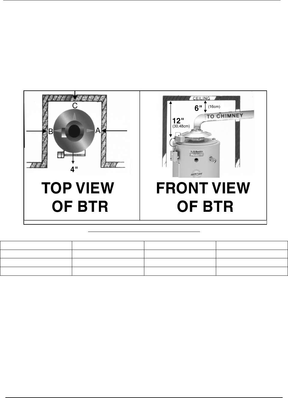
Clearance to Combustibles Table
MODEL A B C
120 - 200 1” (2.54CM) 1” (2.54CM) 1” (2.54CM)
250 - 305 2” (5.08CM) 2” (5.08CM) 2” (5.08CM)
365 - 500 3” (7.75CM) 3” (7.75CM) 3” (7.75CM)
A 24 inch clearance for all serviceable parts is recommended. Clearances may vary
between BTR models – See instruction manual or the label on the heater, for clearances
applicable to your specific model.
CLEARANCES FROM COMBUSTIBLES
BTR TANK TYPE HEATERS
SERVICE HANDBOOK
A.O. Smith Water Products Service Handbook
Irving, Texas ©2000 Training Department
4
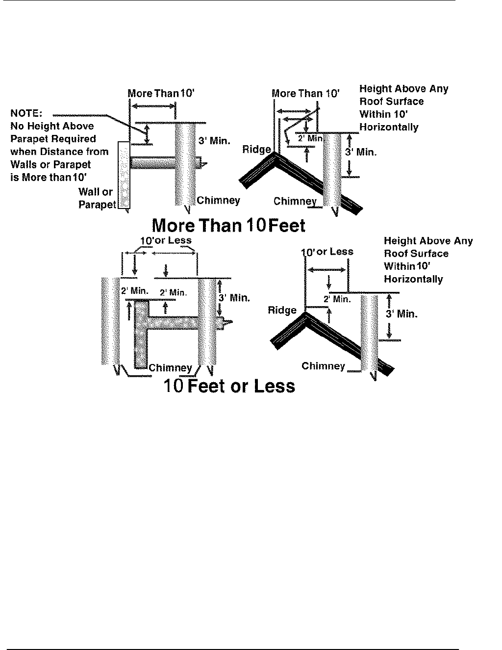
EXTERIOR CLEARANCE
This illustrates the exterior roof clearances for BTR units with natural draft venting. The
vent shall extend at least 3 feet above the highest point where it passes through a roof of
a building, and at least 2 feet higher than any portion of a building within a horizontal
distance of 10 feet (for vents of 12" in diameter or less). (NFPA 54 ANSI Z 223.1 SEC
7.5.2a). (Sec 7.6.2a may allow reduction to 8 feet with a “ Listed vent cap”).
"Copyright by the American Gas Association. Used by permission of the copyright holder".

BTR TANK TYPE HEATERS
SERVICE HANDBOOK
A.O. Smith Water Products Service Handbook
Irving, Texas ©2000 Training Department
5
AIR FOR COMBUSTION
10 CUBIC FEET OF AIR PER 1,000 BTU
Stoichiometric or theoretical complete combustion requires 10 cubic feet of air per 1000
BTUH input of the gas input. The National Fuel Gas Code also recommends an
additional 2.5 cu.ft. of "excess" air. This 12.5 cu.ft minimum supply air per 1000 BTUH
input applies to natural and propane gas models.
The National Fuel Gas Code also specifies minimum make-up air opening sizes for
various building installations. (Ref: NFPA 54, ANSI Z223.1, sec 5.3)
2.5 CU.
FT.
EXCESS
AIR
10 CU.
FT.
COMB.
AIR
+
1
1
1,
,
,0
0
00
0
00
0
0
B
B
BT
T
TU
U
U
BTR TANK TYPE HEATERS
SERVICE HANDBOOK
A.O. Smith Water Products Service Handbook
Irving, Texas ©2000 Training Department
6
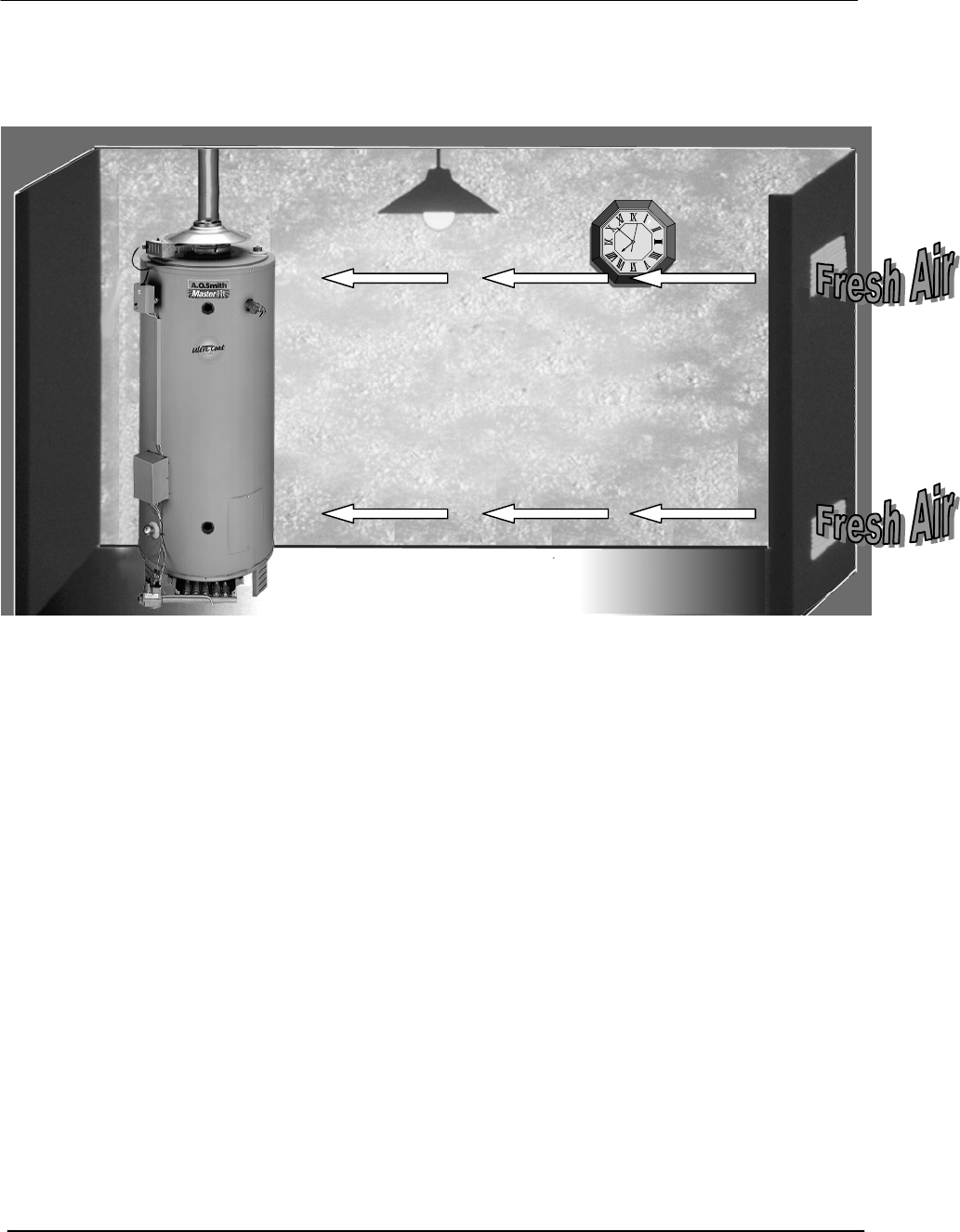
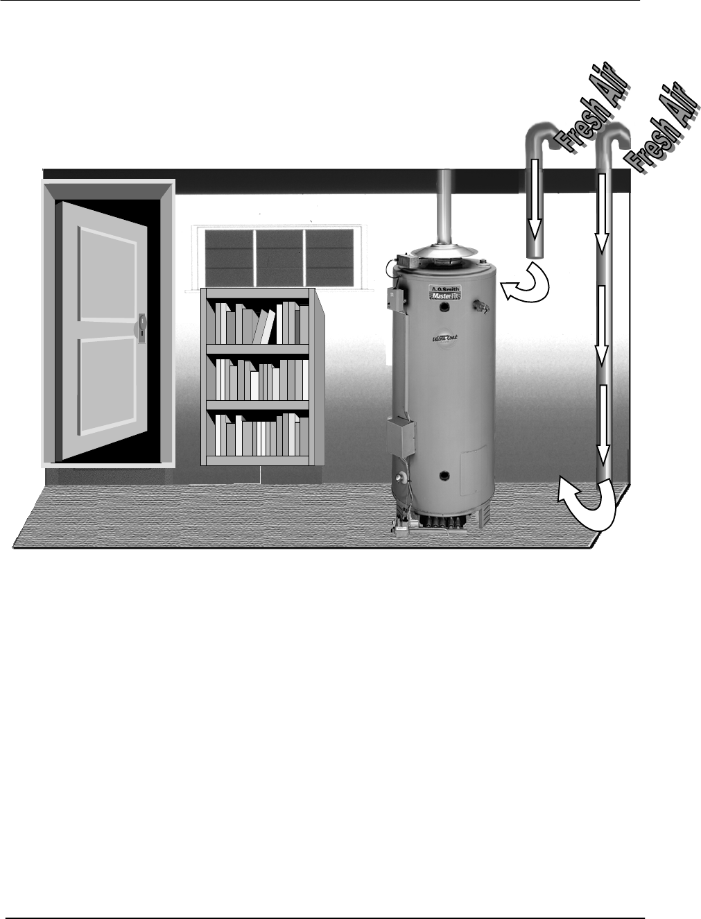
MAKE-UP AIR
DIRECT COMMUNICATION
A fresh supply of make-up air for combustion can be supplied to the heater through
make-up air ducts which directly communicate with the out of doors. Two openings are
required - one within 12 inches of the top of the enclosure and one within twelve inches of
the bottom of the enclosure. Each opening shall have a free area of not less than 1
square inch per 4000 BTUH of the total input of all appliances within the enclosure.
The lower opening is primarily providing combustion air. The upper opening is providing
vent dilution air and acts as a relief opening for flue gases should the vent become
obstructed or a downdraft condition occur. Additionally, when the heater is installed in a
confined space and communicating with the outdoor air, one permanent opening,
commencing within 12 in. (30 cm) of the top of the enclosure, shall be permitted where
the equipment has clearances of at least 1 in. (2.5 cm) from the sides and back and 6 in.
(16 cm) from the front of the appliance. The opening shall directly communicate with the
outdoors and shall communicate through a vertical or horizontal duct to the outdoors or
spaces (crawl or attic) that freely communicate with the outdoors, and shall have a
minimum free area of:
a. 1 sq. in. per 3000 BTU per hr (7 cm2per kW) of the total input of all equipment
located in the enclosure, and
b. Not less than the sum of the areas of all vent connectors in the confined space.
1 Square
Inch Per
4,000
BTUH
BTR TANK TYPE HEATERS
SERVICE HANDBOOK
A.O. Smith Water Products Service Handbook
Irving, Texas ©2000 Training Department
7
MAKE-UP AIR
VERTICAL DUCTS
Often it is more practical to install vertical make-up air ducts to the out doors. Again, two
openings are required - one within 12 inches of the top of the enclosure and one within
twelve inches of the bottom of the enclosure. Each opening shall have a free area of not
less than 1 square inch per 4000 BTUH of the total input of all appliances within the
enclosure.
1 Square
Inch Per
4,000
BTUH
BTR TANK TYPE HEATERS
SERVICE HANDBOOK
A.O. Smith Water Products Service Handbook
Irving, Texas ©2000 Training Department
8
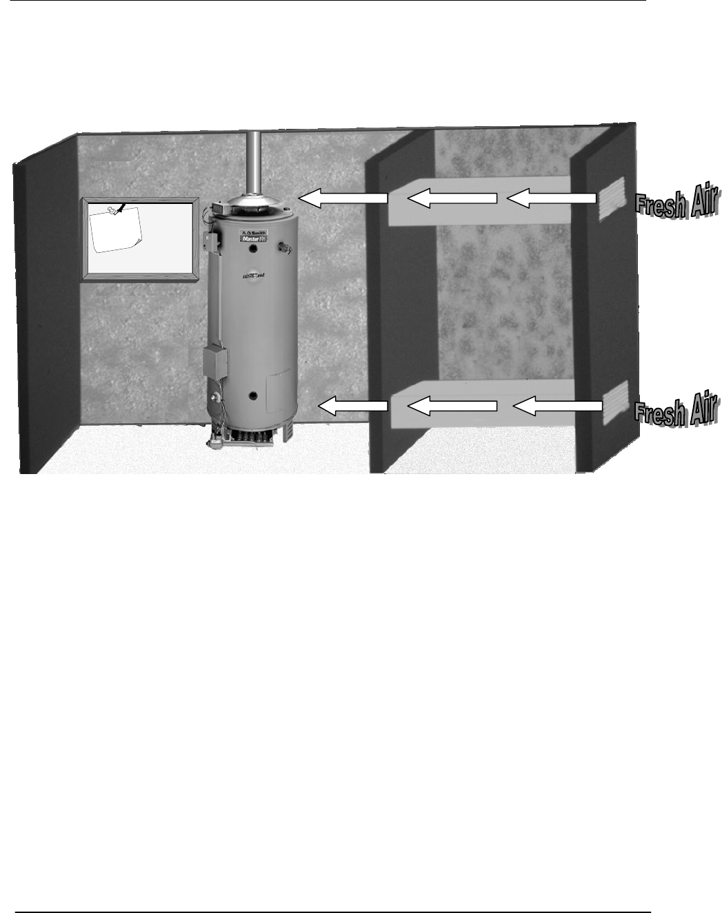
MAKE-UP AIR
HORIZONTAL DUCTS
When the heater is installed in an interior room with no roof access for vertical ducts,
horizontal make-up air ducts should be installed. When using horizontal ducts, two
openings are required - one within 12 inches of the top of the enclosure and one within
twelve inches of the bottom of the enclosure. Each opening shall have a free area of not
less than 1 square inch per 2000 BTUH of the total input of all appliances within the
enclosure.
1 Square
Inch Per
2,000
BTUH
Dail
y
Schedule
BTR TANK TYPE HEATERS
SERVICE HANDBOOK
A.O. Smith Water Products Service Handbook
Irving, Texas ©2000 Training Department
9
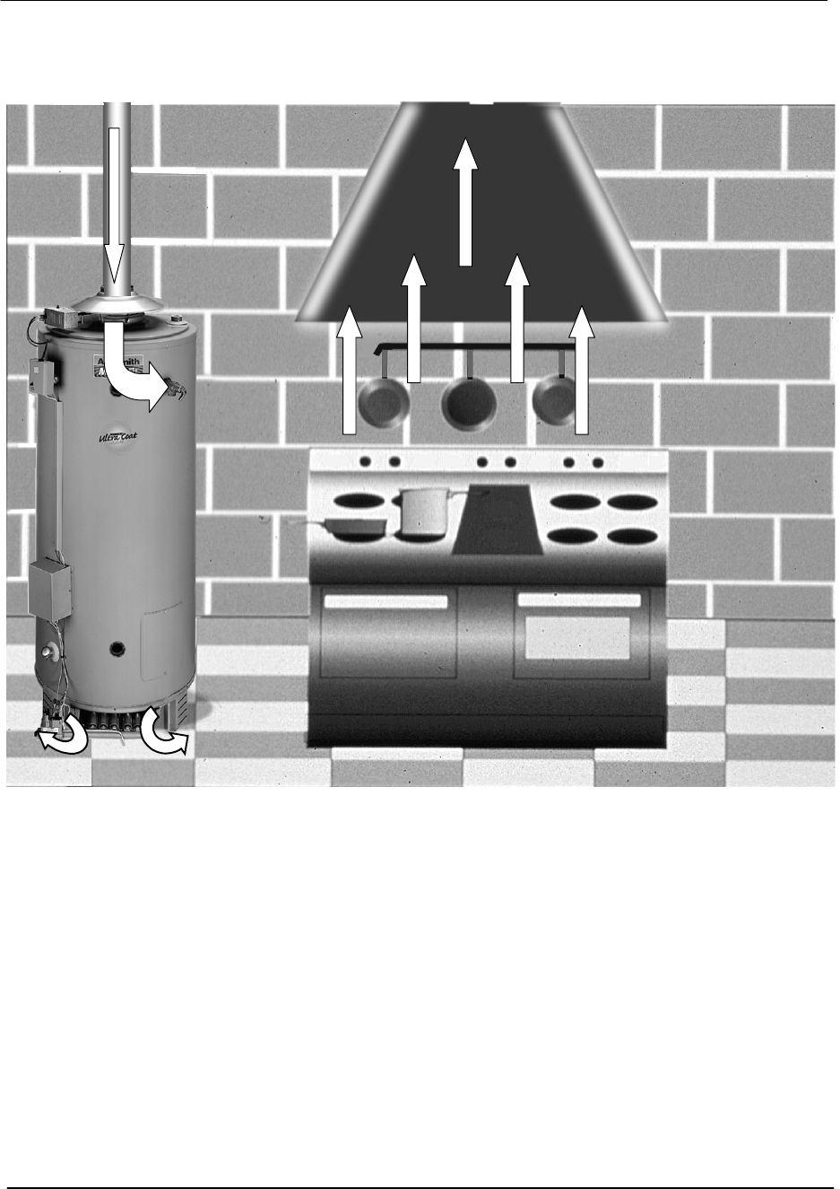
INSUFFICIENT MAKE-UP AIR
BACKDRAFT
Insufficient make-up air is a major cause of combustion problems. One common example
is in a restaurant installation where exhaust vent equipment was not considered in sizing
make-up air requirements. This may result in air being backdrafted by the restaurant
exhaust equipment through the heater causing flue gas spillage, flame roll out, improper
combustion, inconsistent pilot operation, and/or erratic heater shut down.
BTR TANK TYPE HEATERS
SERVICE HANDBOOK
A.O. Smith Water Products Service Handbook
Irving, Texas ©2000 Training Department
10
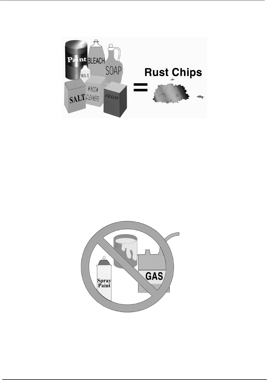
CONTAMINATED AIR
Along with adequate make-up air, the quality of the air is important. Contaminants in
combustion air can lead to premature heater failure. Vapors from bleaches, soaps,
waxes, salts, etc. are drawn into the combustion chamber with the make-up air and, once
fired, mix with water vapor in the gases to form extremely corrosive hydrochloric or
hydrofluoric acid and other corrosive byproducts.
AIR FOR COMBUSTION
Flammable Items
Flammable items, pressurized containers or any other potentially hazardous articles must
never be placed on or adjacent to the heater. Open containers of flammable material
should not be stored or used in the same room with the heater.
BTR TANK TYPE HEATERS
SERVICE HANDBOOK
A.O. Smith Water Products Service Handbook
Irving, Texas ©2000 Training Department
11
GAS PRESSURE REQUIREMENTS
Natural Gas Propane Gas
Maximum Supply Pressure 13.8" w.c. 13.8" w.c.
Minimum Supply Pressure 4.5" w.c. 11" w.c.
Manifold Pressure 3.5 " w.c. 10" w.c.
The supply gas pressure is normally measured at the dirt leg or at the gas pressure
tapping on the gas supply shutoff valve. This reading must be measured with 'flowing'
gas.
The manifold gas pressure is measured at the manifold pressure tap of the gas valve
when the gas is flowing.
Supply Gas
Dirt Leg
Manifold
Gas Port
Manifold
Pressure
Tap
BTR TANK TYPE HEATERS
SERVICE HANDBOOK
A.O. Smith Water Products Service Handbook
Irving, Texas ©2000 Training Department
12
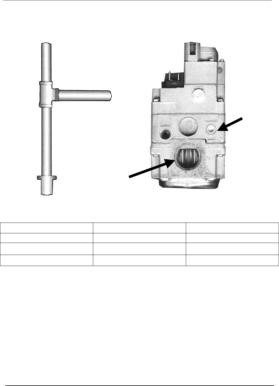
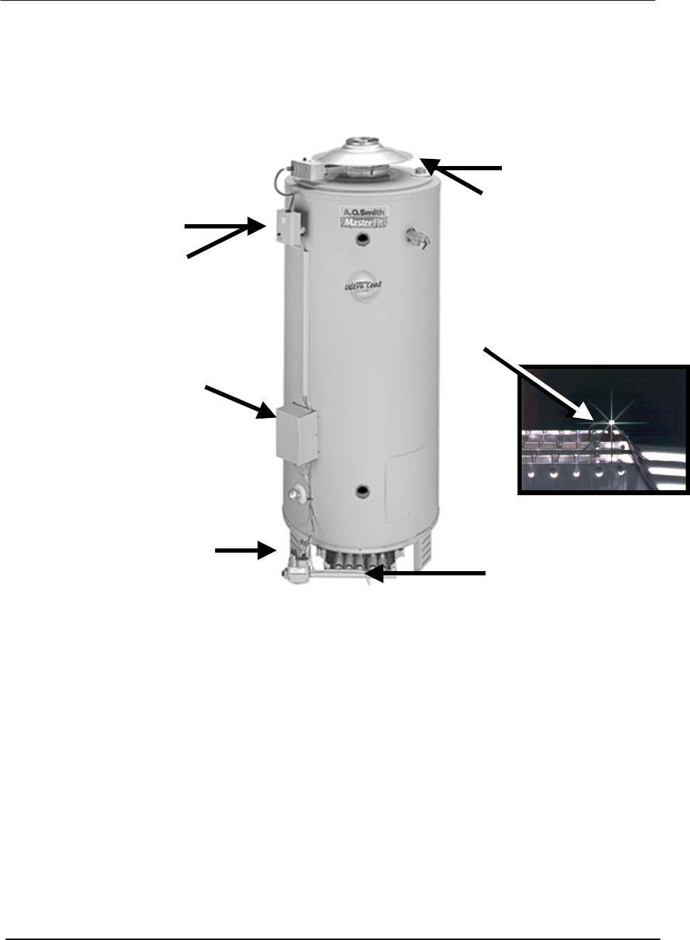
BTR GAS VALVE
The gas valves used on all BTR water heaters are
24 volt AC combination step opening gas valves.
They incorporate the pilot valve, main valve, and gas
pressure regulators into one body. The inlet view of
the valve features a filter screen and the top knob.
The top knob is a manual on/off gas control for both
the pilot and main gas valves. When the top knob is
placed on the black mark, gas is supplied only to the
pilot valve.
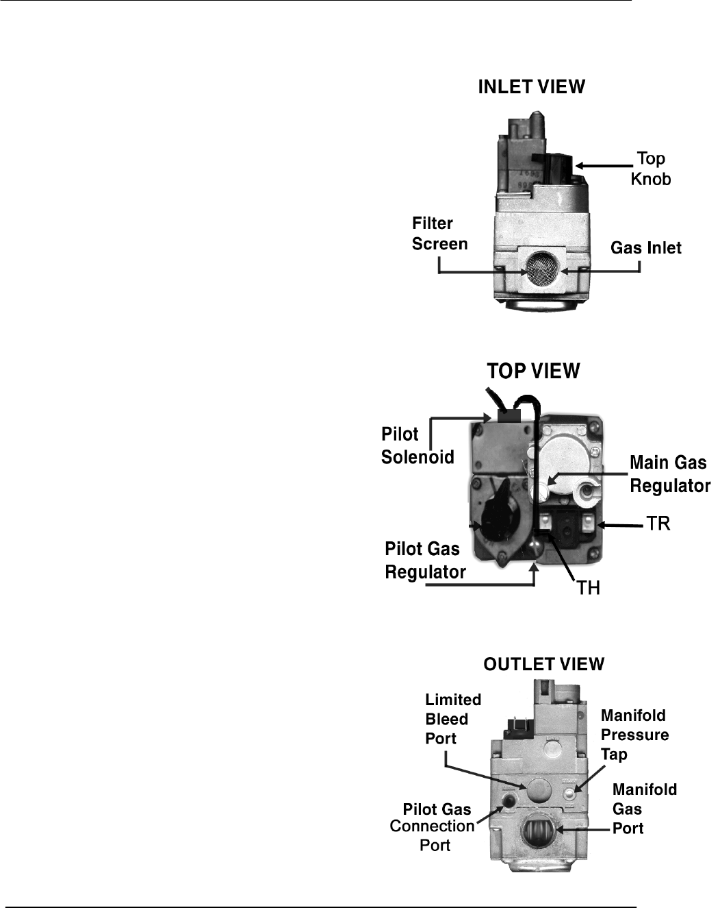
On the top view, we see the pilot solenoid and
pilot and main gas regulators. The top view also
displays the “TH and “TR” terminals. The pilot
gas regulator is found under its cover screw. It is
factory preset at 3.5”w.c. but can be adjusted from
2.5 to 5 inches water column. The main gas
regulator is found under its cover screw. It is
factory preset to 3.5 inches w.c. and adjusts gas
pressure output from 2.5 to 5 inches water
column. The two electrical terminals are marked
TH and TR. The TH terminal is the common
between the pilot valve solenoid coil and the main
valve solenoid coil. The other wire emerging from
the pilot solenoid connects to the pilot valve
electrical output on the IID (terminal PV). The TR
terminal connects directly to the main valve
electrical output from the IID module
(terminal MV).
On the outlet view of the gas valve, we see the
pilot gas connection port, manifold gas connection
port, a limited bleed vent port, the manifold gas and
pressure tap.
See step 18 for BTR-500 gas valve illustration
BTR TANK TYPE HEATERS
SERVICE HANDBOOK
A.O. Smith Water Products Service Handbook
Irving, Texas ©2000 Training Department
13
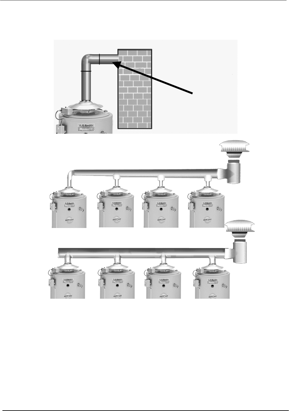
VENTING
Atmospheric Multiple Heaters
All BTR water heaters are classified by ANSI as category I (non-condensing, negative
pressure venting) appliances. They are approved for type B vent.
For larger applications, BTR water heaters can be common vented together either in a
tapered manifold or constant size manifold. (Follow National Fuel Gas Code
requirements for sizing and installation.)
BTRs may be common vented only with other category I appliances. (See venting
section in the National Fuel Gas Code).
A minimum of ¼” rise
per foot of horizontal
vent is re
q
uired.
Chimne
y
BTR TANK TYPE HEATERS
SERVICE HANDBOOK
A.O. Smith Water Products Service Handbook
Irving, Texas ©2000 Training Department
14
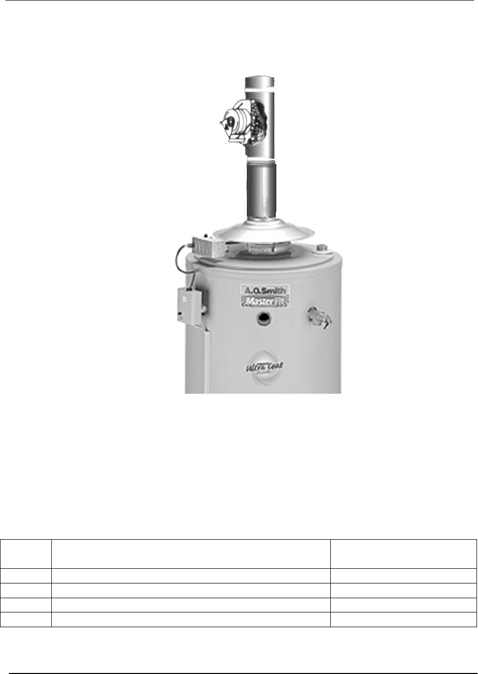
DRAFT INDUCER
Draft inducers can be used with BTR water heaters to mechanically aid a lazy chimney in
vertical vent applications. They are not designed to allow “through-the-wall” vent
installations. (See Power Venter)
SINGLE UNIT INSTALLATION
When mechanically venting, the following items are required:
Qty Description Part No.
1 Draft Inducer (up to 300,000Btuh) 90909
1 Draft Inducer (up to 305,000 thru 500,000 Btuh) 90910
1 Draft Prover Switch 95220
1 Relay Switch 96695
BTR TANK TYPE HEATERS
SERVICE HANDBOOK
A.O. Smith Water Products Service Handbook
Irving, Texas ©2000 Training Department
15
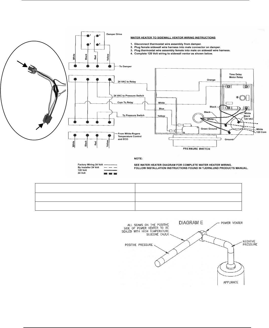
POWER VENT KITS FOR SIDEWALL VENTING
Water Heater Models Part Number
BTR-120-200 193933-0
BTR-250-500 193933-1
BTR water heaters can be used
with power vent kits for sidewall
venting. A.O. Smith offers power
vent kits for use on installations with
a maximum of 100 equivalent feet
of vent piping. The power vent kits
also use type B vent materials.
When power venting, specific
exterior clearances must be
maintained, as outlined in the
National Fuel Gas Code. (NFPA
54, ANSI A223.1, sec 7.8)
Male plug
to Cable
Female plug
to Damper
40’, Power Venter
cablewith“Y”
connect
BTR TANK TYPE HEATERS
SERVICE HANDBOOK
A.O. Smith Water Products Service Handbook
Irving, Texas ©2000 Training Department
16
BTR SEQUENCE OF OPERATION
1. Thermostat calls for heat 2. Flue dam
p
er o
p
ens
3. Intermittent
I
g
nition Control
5. Main gas valve opens
7. Thermostat satisfies
4. Pilot gas opens,
Pilot sparks and
flame
p
roves
6. Main burner i
g
nites
8. Main and pilot
burners "OFF"
SEQUENCE OF OPERATION
To understand BTR tank type water heaters, an examination of their sequence of
operation is necessary.
When the thermostat calls for heat, the relay in the draft hood assembly activates, de-
energizing the flue damper motor. The damper opens and power flows to the IID
(Intermittent Ignition Device). This activates the IID module to open the pilot valve
and begin sparking at the pilot burner assembly. Once the pilot flame is established
and confirmed back to the IID, the sparking is stopped and the main gas valve is
opened, allowing gas flow to the main burner. When the thermostat satisfie’s, main
and pilot gas is shut off.
9. Flue dam
p
er closes
BTR TANK TYPE HEATERS
SERVICE HANDBOOK
A.O. Smith Water Products Service Handbook
Irving, Texas ©2000 Training Department
17
BTR ELECTRICAL SEQUENCE
100 – 109 Series

BTR TANK TYPE HEATERS
SERVICE HANDBOOK
A.O. Smith Water Products Service Handbook
Irving, Texas ©2000 Training Department
18
BTR ELECTRICAL SEQUENCE OF OPERATION
Motor Opens
Damper
Power to Damper
#2 Interrupted
Series 110 and 111
Effikal
Series 110 and 111
Effikal
IID Module
(24V) Receives Voltage
Module (PV) Teminal
Sends 24V to Pilot Coil
Module (Spark) Sends
10,000V Spark to Pilot
Spark Stops
Dam per Motor Energized
and Dam per Closed
Power to Damper
Relay (4) Interupted
Them ostat O pens
Main Burner Heats Tank
Module (MV)
Terminal Sends 24V
To Main Gas Coil
90 Second Trial /
5 Minute Delay Between
Trials - C on tin u ously
Pilot Ignites and Proves Flame
Cam On Damper Blade
Closes Proving End Switch
Damper Spring Opens
Dam per Blade
Motor Relay Interrupts
Power to Motor
Therm ostat Closed
High Limit Closed
Tank Tem perature
Motor Closes
Damper
High Limit (ECO)
Closed
Tank Tem perature
Satisfied
24V Transform er
On / OFF Switch "ON"
120 Vac to Junction Box
BTR TANK TYPE HEATERS
SERVICE HANDBOOK
A.O. Smith Water Products Service Handbook
Irving, Texas ©2000 Training Department
19
TROUBLESHOOTING BTR WATER HEATERS
To troubleshoot a BTR water heater check that:
• 120 VAC is supplied to the heater
• the tank is full of water
• gas is supplied to the unit
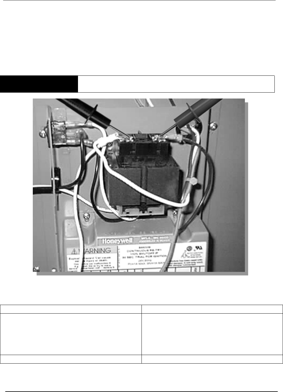
STEP 1 TEST THE TRANSFORMER
STEP 1 - TO TEST THE TRANSFORMER - Using a multimeter, test for 24 VAC
between the secondary transformer terminals.
IF THEN
The meter does not read 24 VAC: • Check that the 120 VAC is supplied
from the On/Off Switch – if not, replace
switch.
• Check that the 120 VAC is supplied
from transformer.
The meter reads 24 VAC: • Go to step 2.
BTR TANK TYPE HEATERS
SERVICE HANDBOOK
A.O. Smith Water Products Service Handbook
Irving, Texas ©2000 Training Department
20
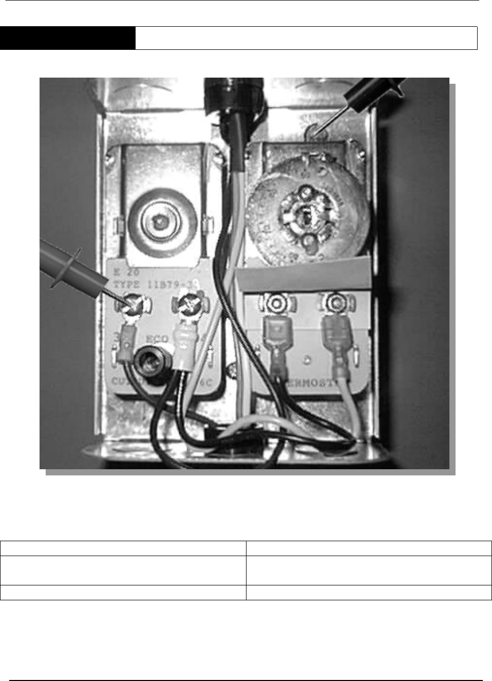
STEP 2 HIGH LIMIT, LEFT TERMINAL TEST
STEP 2. HIGH LIMIT, LEFT TERMINAL TEST. Test for 24 VAC between the left high
limit terminal and ground.
IF THEN
The meter does not read 24 VAC: • Check wiring between transformer and
high limit.
The meter reads 24 VAC: • Go to Step 3.
Note: The high limit (Energy Cut Off) opens if the tank water temperature exceeds 205
degrees. The control is resettable (manually) when the tank water temperature drops
below 185 degrees.
BTR TANK TYPE HEATERS
SERVICE HANDBOOK
A.O. Smith Water Products Service Handbook
Irving, Texas ©2000 Training Department
21
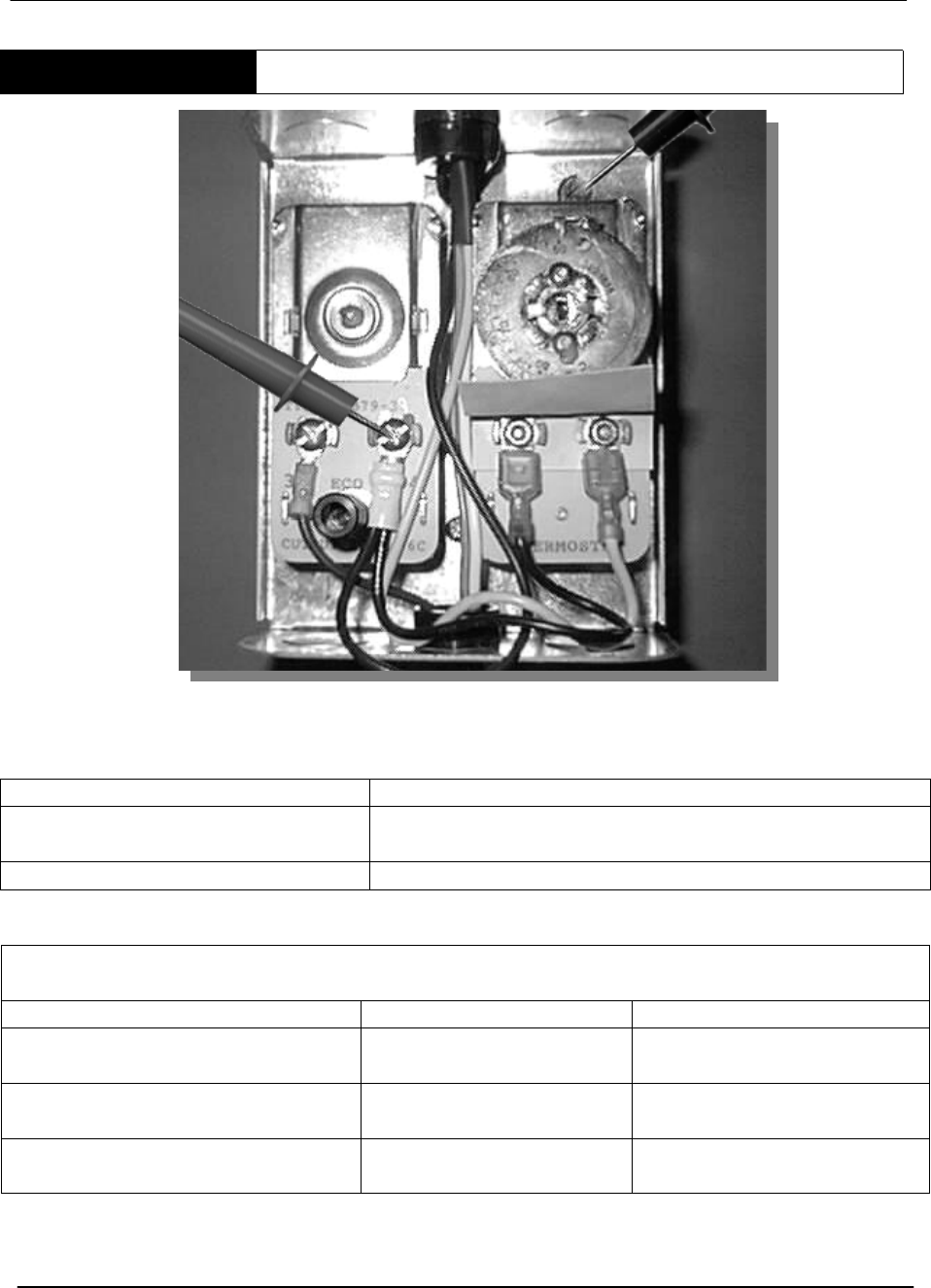
STEP 3 TEST HIGH LIMIT RIGHT TERMINAL
STEP 3. TO TEST HIGH LIMIT RIGHT TERMINAL. Ensure that the jumper wire
between the high limit and thermostat is connected, and the damper motor power line is
connected. Test for 24 VAC between the high limit right terminal and ground.
IF THEN
The meter does not read 24 VAC: • Push the reset button and redo the test (storage
water temperature below 185 degrees).
The meter reads 24 VAC: • Go to step 4.
After Push in Reset - 24 VAC is now present
Reasons For Resetting
Condition Cause Solution
High limit open Never set on initial
installation
Push high limit button
Excessive water temperature Faulty thermostat Replace dual control
Heater shut down before
reaching thermostat setting
Faulty high limit Replace dual control
Note: The right terminal of the high limit has a jumper wire connected to the left terminal of the
thermostat. There is also a black wire connecting to the damper motor assembly. This black wire
supplies power to the motor to close the damper during periods of standby.
BTR TANK TYPE HEATERS
SERVICE HANDBOOK
A.O. Smith Water Products Service Handbook
Irving, Texas ©2000 Training Department
22
STEP 4 INSPECT THE DAMPER
STEP 4. INSPECT THE DAMPER. Lower the thermostat setting so the unit will not be
calling for heat, then inspect the damper.
IF THEN
If the damper is open: • Go to step 5.
If the damper is closed: • Go to step 7.
Note: If the water temperature in the tank is below 120 degrees F, temporarily disconnect the
jumper wire between the high limit and thermostat to simulate a satisfied thermostat.
STEP 5 CHECK THE PC BOARD
STEP 5. CHECK THE PC BOARD. Test for 24 VAC between the black PC board wire
connection and ground.
IF THEN
24 VAC is not present: • Check the black wire connections
between PC Board and high limit.
24 VAC is present: • Go to step 6.
E
Ef
ff
fi
ik
ka
al
lD
Da
am
mp
pe
er
rO
Op
pe
en
n
BTR TANK TYPE HEATERS
SERVICE HANDBOOK
A.O. Smith Water Products Service Handbook
Irving, Texas ©2000 Training Department
23
STEP 6 PC BOARD MOTOR TEST
STEP 6. PC BOARD/MOTOR TEST. Check for 24 VAC between the two motor lead
terminals of the PC board. Disconnect the wires for this test.
IF THEN
24 VAC is not present: • Replace the board (AOS part # 6522)
and go to step 7. The board and relay
are one piece. Regardless of which
part is defective, both parts should be
changed.
Voltage is present: • This verifies that the motor is receiving
power but not closing the damper.
• Replace the motor (AOS part # 6521)
and go to step 7.
Note: The service switch may be used to bypass the damper, while waiting for a replacement part.
WARNING - In the event of damper motor failure, verify that the damper is in the "open"
position before utilizing the service switch. (BTR Series 106/107 and some prior series –
changed from momentary push button to service switch).
Service Switch
Motor Lead
Terminals
BTR TANK TYPE HEATERS
SERVICE HANDBOOK
A.O. Smith Water Products Service Handbook
Irving, Texas ©2000 Training Department
24
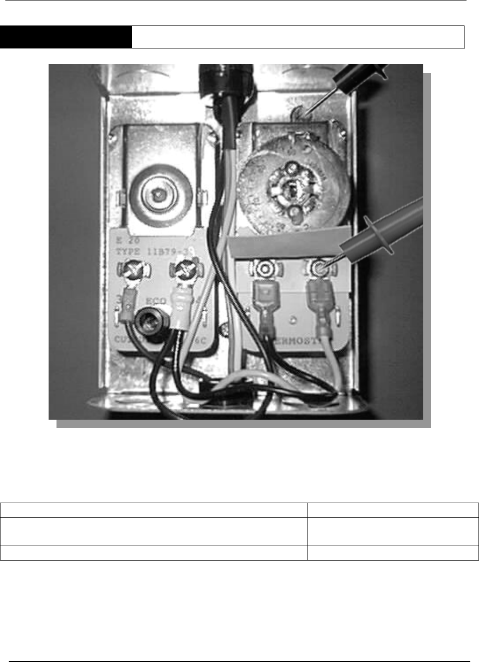
STEP 7 THERMOSTAT TEST
STEP 7. THERMOSTAT TEST. Set the thermostat to call for heat. Using your
multimeter, test for 24 VAC between right terminal and ground.
IF THEN
The meter does not read 24 VAC and the jumper wire
between the high limit and the thermostat is in place:
• Replace the thermostat
The meter reads 24 VAC: • Go to step 8.
Note: If the high limit to thermostat jumper wire was disconnected earlier to simulate a satisfied
thermostat, reconnect the jumper to the terminals.
Note: A yellow wire from this thermostat terminal connects to the damper PC board.
BTR TANK TYPE HEATERS
SERVICE HANDBOOK
A.O. Smith Water Products Service Handbook
Irving, Texas ©2000 Training Department
25
GO TO PAGE 27 FOR DAMPER TESTS OF EFFIKAL EQUIPPED (SERIES 110, 111 AND
RETROFIT) MODELS
STEP 8 DAMPER INPUT TEST
STEP 8. DAMPER INPUT TEST. Test for 24 VAC between the yellow wire on the PC
board and ground. Effikal – Check from orange wire to neutral
IF THEN
24 VAC is not present: • Check the black wire connections
between the PC board and high limit.
24 VAC is present • Go to step 6.
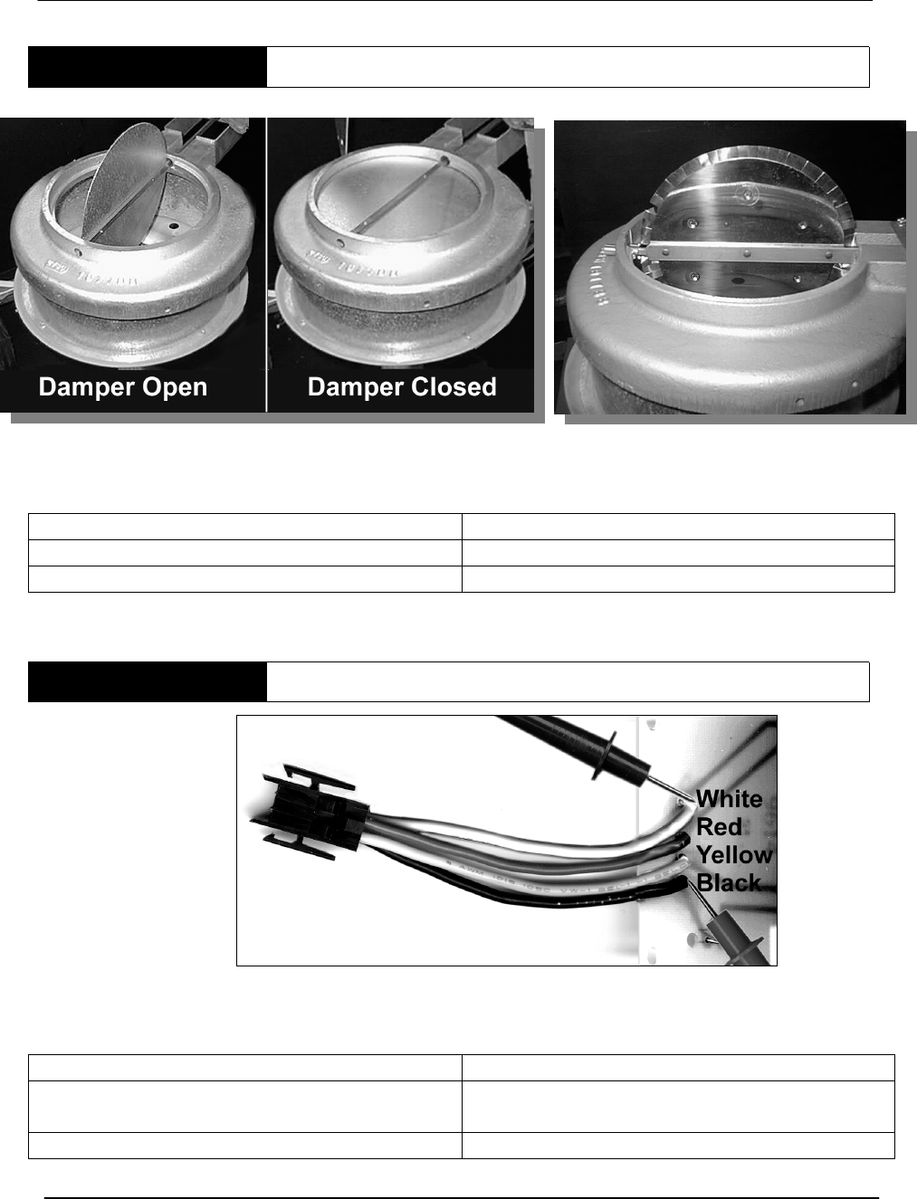
STEP 9 TEST THE DAMPER
STEP 9. TEST THE DAMPER. Visually check the damper blade position.
IF THEN
The damper does NOT open fully: • Replace the damper assembly
The damper DOES open fully: • Go to step 10.
Test from
Orange
wire to
Black
(neutral)
BTR TANK TYPE HEATERS
SERVICE HANDBOOK
A.O. Smith Water Products Service Handbook
Irving, Texas ©2000 Training Department
26
STEP 10 TEST DAMPER OUTPUT
STEP 10. TEST DAMPER OUTPUT. On a call for heat, the damper relays receives
power through the yellow wire and power to the motor is interrupted. Then, the motor
clutch is disengaged and the damper opens. The damper proves it is open via an end
switch before power flows through the red wire from the PC board.
Place the red test probe on the solder joint of the red wire connection to the damper PC
board.
IF THEN
The meter does not read 24 VAC and the
end switch is closed:
• Replace the PC board
The meter reads 24 VAC • Go to step 11.
Note: The spring rotates the damper blade assembly to the open position. This closes an end
switch.
BTR TANK TYPE HEATERS
SERVICE HANDBOOK
A.O. Smith Water Products Service Handbook
Irving, Texas ©2000 Training Department
27
Damper
1234
Black
Red
Yellow
White
Orange Brown Yellow Black
Male Plug
From Heater
21
3
4
Female Plug
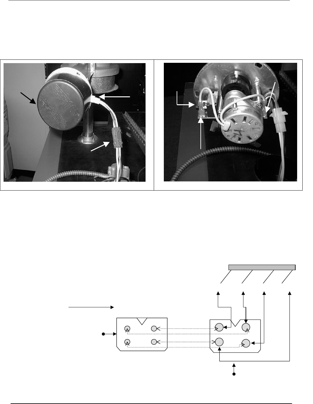
EFFIKAL DAMPER
BTR Series 110 and 111 began using the motor open; motor close, Effikal Damper. The
wiring colors from the damper PC Board are different from previous series BTR(C) and
BTC Models.
The heater harness wires still serve the same function:
Service
Switch Adapter
Plug
Heater
Harness
Service
Switch
Motor
Lead
Terminal
Motor
Lead
Motor
Effikal Control Cover (Photo of kit mounting) Effikal Style
Black – 24V Constant if high limit closed
Yellow – 24V To damper if the thermostat is closed
Red – 24V From damper to IID if damper closes end switch
White–Neutral
(
common
)
BTR TANK TYPE HEATERS
SERVICE HANDBOOK
A.O. Smith Water Products Service Handbook
Irving, Texas ©2000 Training Department
28
HARNESS CHART
Heater Harness Function Damper Harness
Black 24V Hot 1-Brown
Yellow 24V from Therm 2-Orange
Red 24V from damper 3-Yellow
White 24V common 4-Black
Series 110 and 111 heaters and converted model BTR(C) and BTC heaters with Effikal
Dampers.
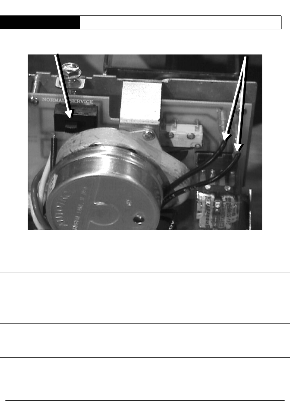
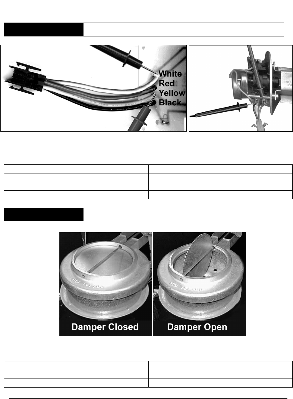
NORMAL OPERATION
Condition:
• Heater on standby
• Damper closed
• High Limit closed
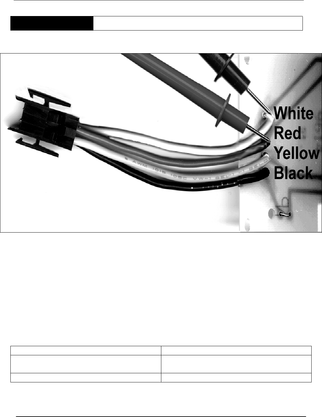
STEP A
TEST FOR 24VAC BETWEEN BLACK (COMMON)
AND BROWN
STEP A. TEST FOR 24VAC BETWEEN BLACK (COMMON) AND BROWN
IF THEN
24VAC is present Continue to Step B.
24VAC is not present See Troubleshooting Step A1
Wires are from left to right:
Black iYellow iBrown iWhite

BTR TANK TYPE HEATERS
SERVICE HANDBOOK
A.O. Smith Water Products Service Handbook
Irving, Texas ©2000 Training Department
29
NORMAL OPERATION (continued)
Condition:
• Thermostat closed, damper in process of opening
STEP B TEST FOR 24VAC BETWEEN BLACK AND ORANGE
IF THEN
24VAC is present Continue to Step C.
24VAC is not present See Troubleshooting Step A2
Condition:
• Thermostat closed, damper fully open
STEP C TEST FOR 24VAC BETWEEN BLACK AND YELLOW
IF THEN
24VAC is present Continue to Step 11
24VAC is not present See Troubleshooting Step A3
BTR TANK TYPE HEATERS
SERVICE HANDBOOK
A.O. Smith Water Products Service Handbook
Irving, Texas ©2000 Training Department
30
TROUBLESHOOTING THE EFFIKAL STYLE DAMPER
Condition:
Thermostat closed, damper
STEP A1
TEST BETWEEN BLACK (COMMON) AND BROWN
ON THE DAMPER BOARD
IF THEN
24VAC is present This is correct
24VAC is not present • SeeSteps1thru4
Check the harness plugs connecting heater
and damper for looseness or damage.
Condition:
Thermostat closed, damper in process of opening.
STEP A2 TEST FOR 24VAC BETWEEN BLACK AND ORANGE
IF THEN
24VAC is present This is correct
24VAC is not present • SeeStep7
• Check the harness plug connecting
heater ----or damaged
Wires are from left to right:
Black iYellow iBrown iWhite

BTR TANK TYPE HEATERS
SERVICE HANDBOOK
A.O. Smith Water Products Service Handbook
Irving, Texas ©2000 Training Department
31
TROUBLESHOOTING THE EFFIKAL STYLE DAMPER (continued)
Condition:
Thermostat closed, damper is open fully
STEP A3 TEST FOR 24VAC BETWEEN BLACK AND YELLOW
IF THEN
24VAC is present This is correct – continue to Step 11
24VAC is not present • SeeStep9
• Check the harness plug connecting ----
• Check that cam on shaft rotates with
shaft
• Replace the damper board
BTR TANK TYPE HEATERS
SERVICE HANDBOOK
A.O. Smith Water Products Service Handbook
Irving, Texas ©2000 Training Department
32
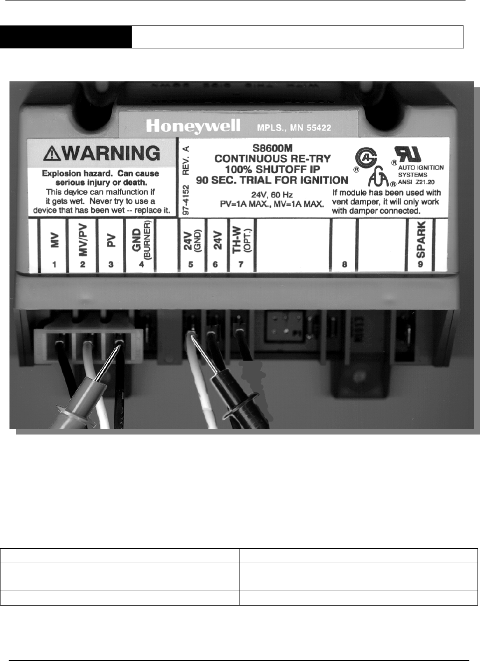
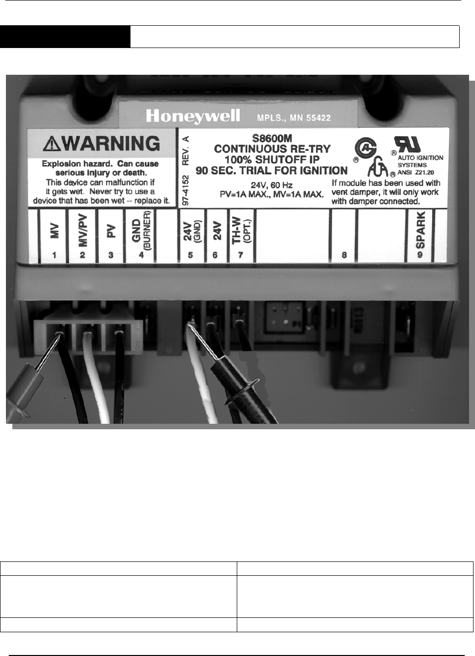
STEP 11 WIRE HARNESS TEST
STEP 11. WIRE HARNESS TEST. Test for 24 VAC between terminal 24V on the IID
module, and 24V (GND).
IF THEN
24 VAC is not present: • Check the wiring harness.
24 VAC is present: • Go to step 12.
Note: This test may be easier to conduct by removing the red wire from the IID terminal. Test for 24
VAC between the red wire and ground. Reconnect the red wire to the 24V terminal after the test.
BTR TANK TYPE HEATERS
SERVICE HANDBOOK
A.O. Smith Water Products Service Handbook
Irving, Texas ©2000 Training Department
33
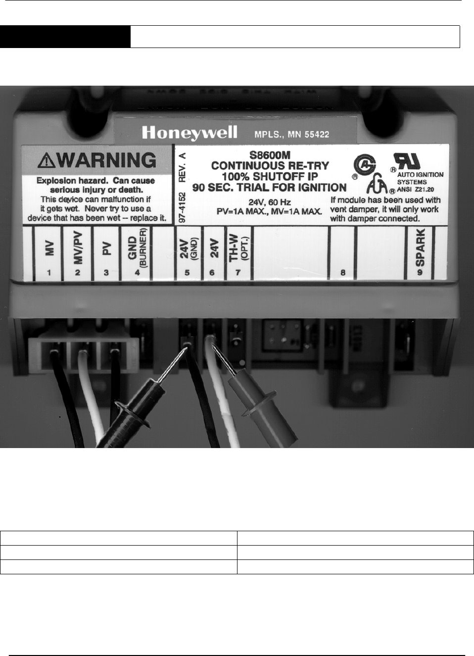
STEP 12 IID MODULE TEST
STEP 12. IID MODULE TEST (Power to the Pilot Valve). Using a multimeter, test for
24 VAC between terminal PV and 24V (GND) on the IID during the 90 second trial for
ignition.
IF THEN
The meter does not read 24 VAC and the
IID module is not between ignition trials:
• Replace the module.
The meter does read 24 VAC: • Go to step 13
BTR TANK TYPE HEATERS
SERVICE HANDBOOK
A.O. Smith Water Products Service Handbook
Irving, Texas ©2000 Training Department
34
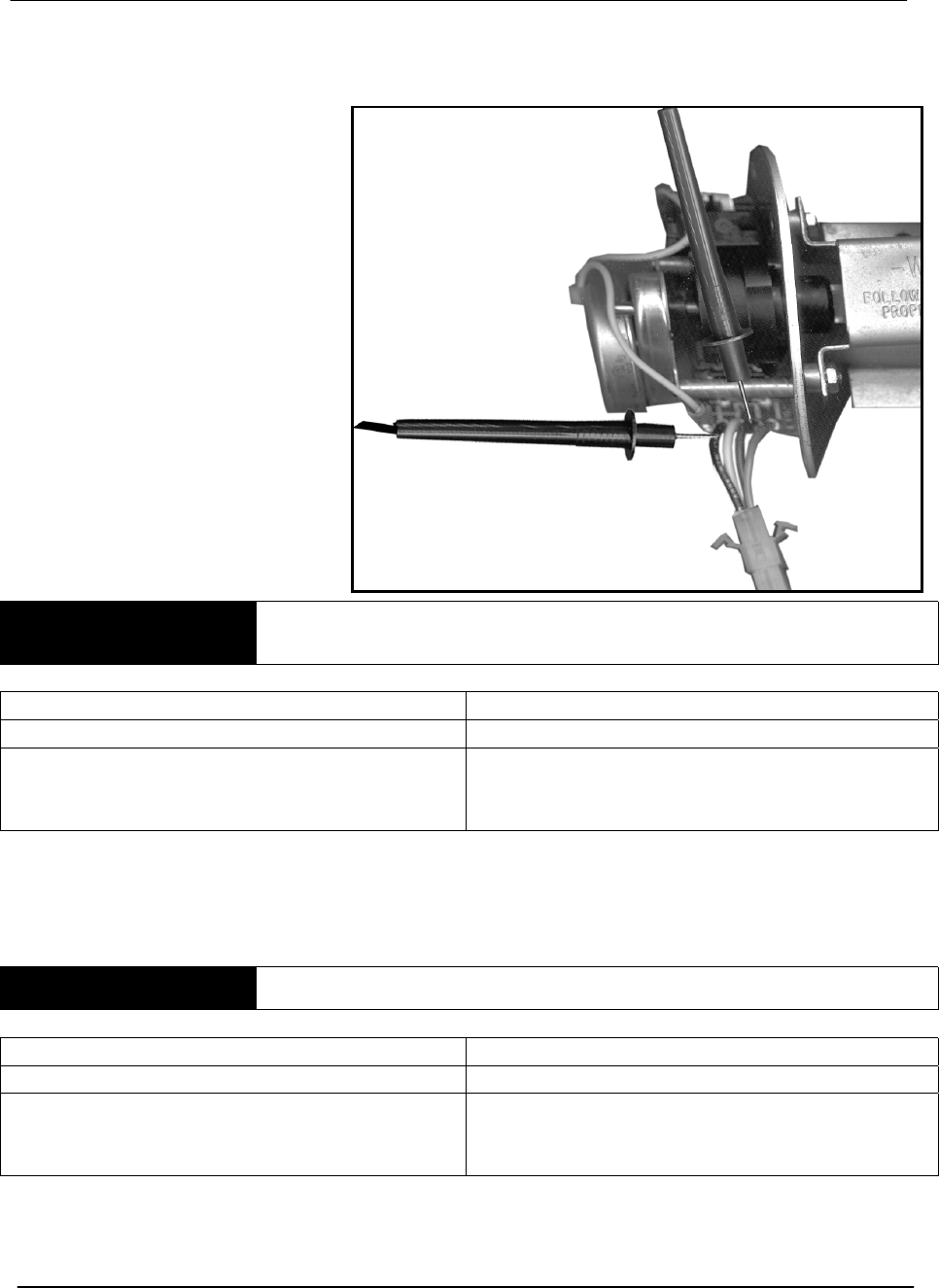
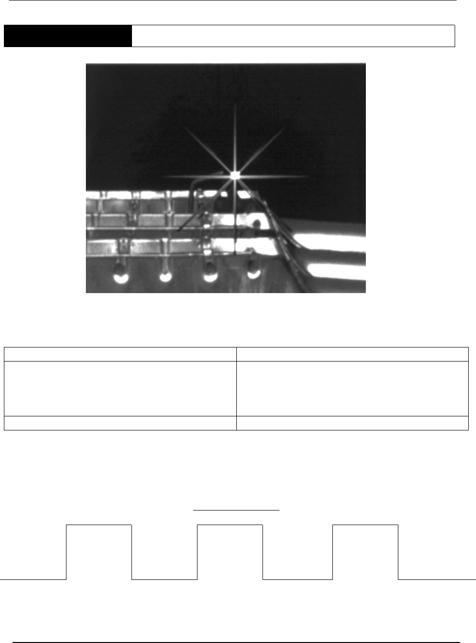
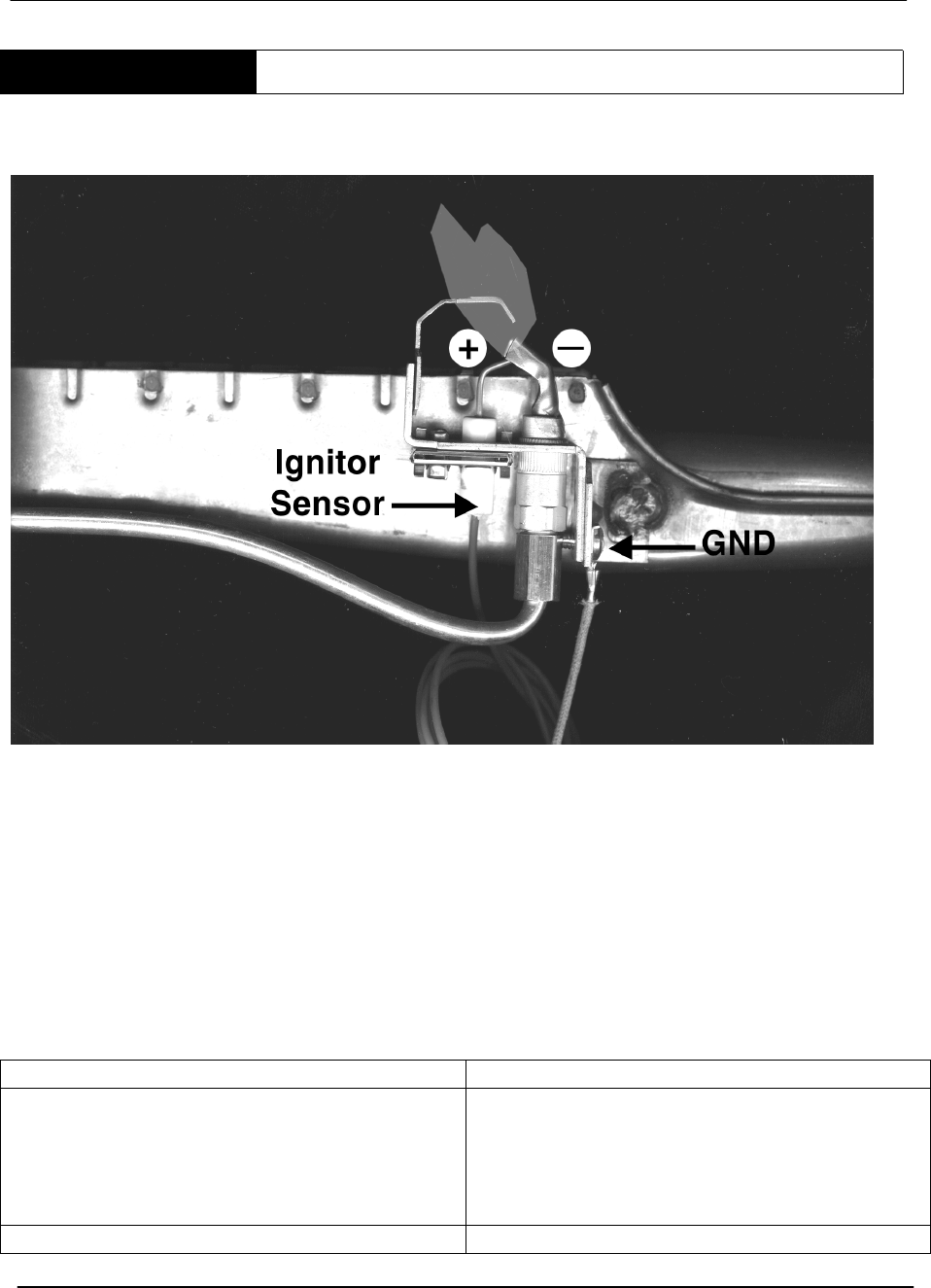
STEP 13 PILOT SPARK TEST
STEP 13. PILOT SPARK TEST. Visually check for spark at the pilot assembly.
Note: The pilot burner mounts on the left side of the main burner.
IF THEN
The igniter is not sparking: Check for:
• A 7/64” spark gap
• Spark cable continuity
• Ground cable continuity
Sparking is present: • Go to step 14.
Power To Module May Be Interrupted To Reset .
Trial for Ignition
90 sec. 5 min. 90 sec. 5 min. 90 sec.
Call for
heat
Sparking No
Sparking
Sparking No
Sparking
Sparking
Continuous
Trial
Sequence
BTR TANK TYPE HEATERS
SERVICE HANDBOOK
A.O. Smith Water Products Service Handbook
Irving, Texas ©2000 Training Department
35
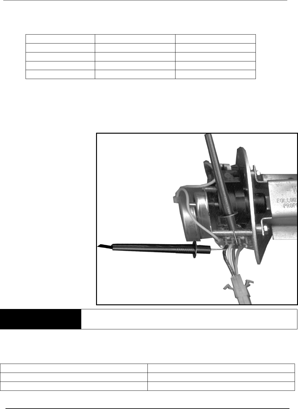
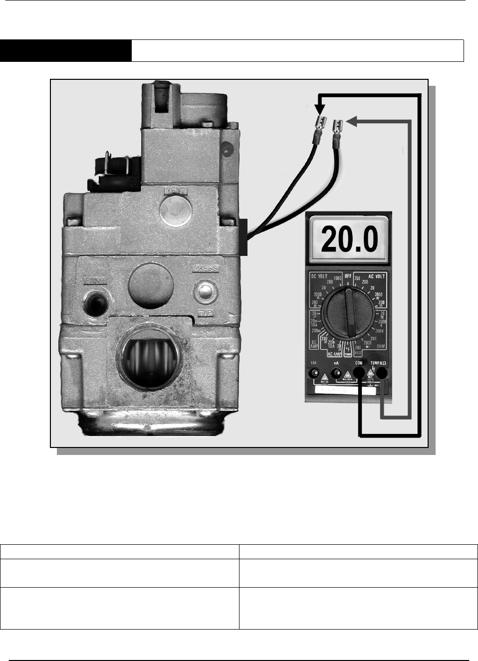
STEP 14A PILOT VALVE - OHM TEST
BTR 120 – 400 GAS VALVE
STEP 14A. PILOT VALVE - OHM TEST. If pilot assembly is sparking but no pilot flame
is established, disconnect the pilot valve solenoid leads. Using a multimeter, (set to read
ohms) test for 20* ohms resistance +/- 5 through the solenoid coil.
IF THEN
The meter dose not read 20 ohms plus or
minus 5:
• Replace gas valve
The meter does read 20 ohms plus or
minus 5:
• Gas valve should work. Also check that
pilot gas is present and pilot tube or
orifice are not blocked
BTR TANK TYPE HEATERS
SERVICE HANDBOOK
A.O. Smith Water Products Service Handbook
Irving, Texas ©2000 Training Department
36
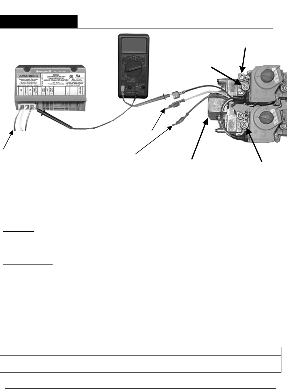
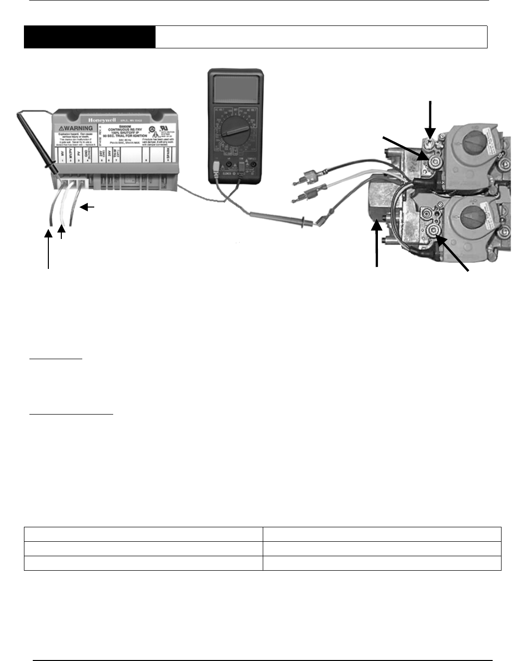
STEP 14B PILOT VALVE TEST – BTR 500 ONLY
STEP 14B. PILOT VALVE TEST – BTR 500 ONLY. Testing the two coils of the
Honeywell VR8404P 5004 gas valve used on the model BTR 500 only. Because of built
in diodes, it is difficult to test for ohms resistance through these coils. The following is a
DC amperage check of the main and pilot coils.
Condition:
• Tank calls for heat
• PV terminal of module has 24 Vac
• No Pilot flame
Test Procedure:
• Turn off power to heater
• Meter set to test for DC amperage (on AOS meters, the black wire is in the
“com” port, the red wire is in the “10A” port, the dial is set to 20M/10A in the DC
AMP test area).
• Blue “PV” wire is disconnected from the ignition PV terminal.
• Install meter in series between gas valve and ignition module – 10A wire to
blue gas valve lead, common wire to PV module terminal.
• Turn power on to heater, after module receives 24V
Test DC Amperage through Pilot coil of gas valve
IF THEN
.75 to .85 DCA is not present: • Replace the gas valve
.75 to .85 DCA is present • Pilot should work if gas (not air) is present to pilot
Power off, reattach blue gas valve wire to PV terminal of module.
RED
WHITE
BLUE
MANIFOLD
PRESSURE
TAP
MANIFOLD
PRESSURE
TAP
PILOT GAS
MANIFOLD
GAS
The MV/PV wire on the IID is connected to the white wire
The MV wire on the IID is connected to the red wire.
BTR TANK TYPE HEATERS
SERVICE HANDBOOK
A.O. Smith Water Products Service Handbook
Irving, Texas ©2000 Training Department
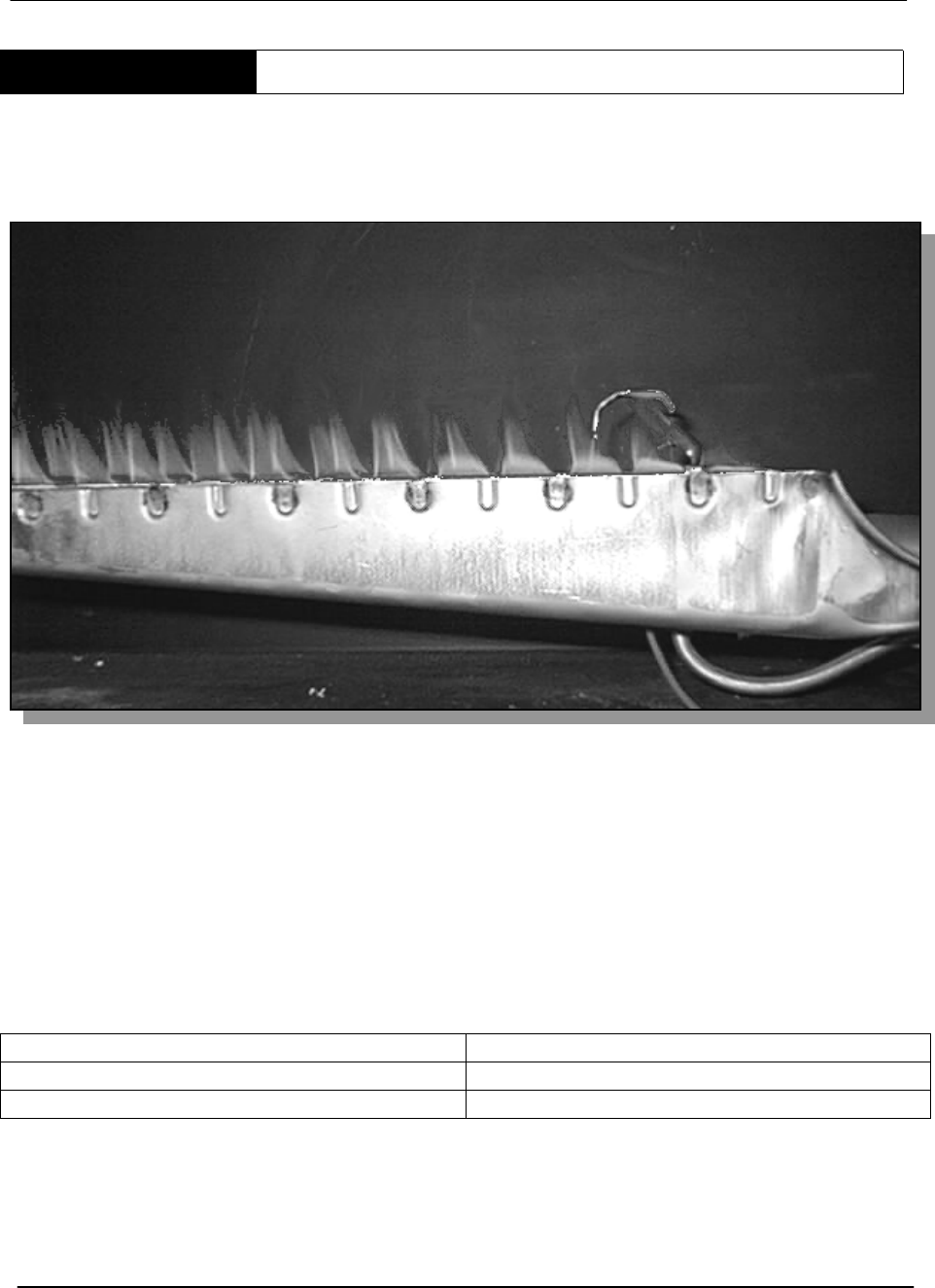
37
STEP 15 MAIN BURNER TEST
Note: BTR series 108 and 109 implemented a new main burner stamping process –
burners appear the same as illustrated.
STEP 15. MAIN BURNER TEST. Visually check for main burner.
IF THEN
The main burner ignites: • Sequence is complete
The main burner does not ignite • Go to step 16
BTR TANK TYPE HEATERS
SERVICE HANDBOOK
A.O. Smith Water Products Service Handbook
Irving, Texas ©2000 Training Department
38
STEP 16 FLAME RECTIFICATION
STEP 16. FLAME RECTIFICATION
Note: Flame rectification means that an alternating current (AC) signal is changed to a direct current (DC)
signal. The pilot flame is the 'switch' which connects the pilot hood to the igniter and ground. If the pilot
hood and igniter sensor had the same surface area, the flame 'switch' would conduct an AC signal.
Because the pilot surface is greater than the igniter surface, the signal becomes a DC current that the
module can interpret. The pilot hood must be properly grounded and the pilot flame must remain in
contact with both surfaces for the flame proving signal to remain constant.
If the signal is broken for just 8 tenths of a second, the heater will cycle off.
Sparking at the pilot will continue if an insufficient signal is received by the module.
Sparking at the pilot will stop almost immediately after the ignition module senses the pilot flame.
IF THEN
Sparking continues after pilot is
established:
• Check wire connections
• Check flame contact between hood
and lighter
• Clean pilot burner surfaces
• Replace pilot assembly
Sparking stops: • Go to step 17.
BTR TANK TYPE HEATERS
SERVICE HANDBOOK
A.O. Smith Water Products Service Handbook
Irving, Texas ©2000 Training Department
39
STEP 17 IID MODULE TEST
Pilot is lit - Sparking has stopped.
STEP 17. IID MODULE TEST (Power to the Main Valve). Using a multimeter, test for
24 VAC between terminal MV on the IID and 24V (GND).
IF THEN
24 VAC is not present: • Replace the IID module. Conduct Step
18 before applying power to
replacement module.
24 VAC is present: • Go to step 18.
BTR TANK TYPE HEATERS
SERVICE HANDBOOK
A.O. Smith Water Products Service Handbook
Irving, Texas ©2000 Training Department
40
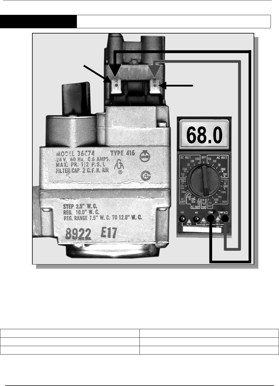
STEP 18A MAIN GAS VALVE CHECK
BTR 120 – 400 GAS VALVE
STEP 18A. MAIN GAS VALVE CHECK. Disconnect wires from gas valve TH and TR
terminals. Using a multimeter, test for 68 ohms plus or minus 5 between TH and TR on
themainvalvecoil.
IF THEN
The meter reads ‘O’ or infinity • Replace the gas valve
The meter reads 68* ohms plus or minus 5 • The main burner will ignite
TH
TR
BTR TANK TYPE HEATERS
SERVICE HANDBOOK
A.O. Smith Water Products Service Handbook
Irving, Texas ©2000 Training Department
41
STEP 18B MAIN GAS VALVE COIL CHECK
STEP 18B. MAIN GAS VALVE COIL CHECK – BTR 500 ONLY
Condition:
• Pilot lights
• Sparking stops
• No main burner ignition
Test Procedure:
• Power off
• Disconnect red, main valve wire from module MV terminal
• Meter set to test for DC amperage
• 10A wire to red gas valve wire, COM wire to MV terminal of ignition module
• Turn power on to heater
• After pilot lights and sparking stops
IF: THEN:
.25 to .35 DC Amps is not present • Replace the gas valve
.25 to .35DCA is present • Main burner gas should ignite.
Be certain to correct you meter wire connections and setting before performing further
tests.
RED
WHITE
BLUE
MANIFOLD
PRESSURE
TAP
MANIFOLD
PRESSURE
TAP
PILOT GAS
MANIFOLD
GAS
The PV wire is connected to the blue wire
The MV/PV wire on the IID is connected to the white wire.
The MV wire is disconnected from the gas valve.
BTR TANK TYPE HEATERS
SERVICE HANDBOOK
A.O. Smith Water Products Service Handbook
Irving, Texas ©2000 Training Department
42
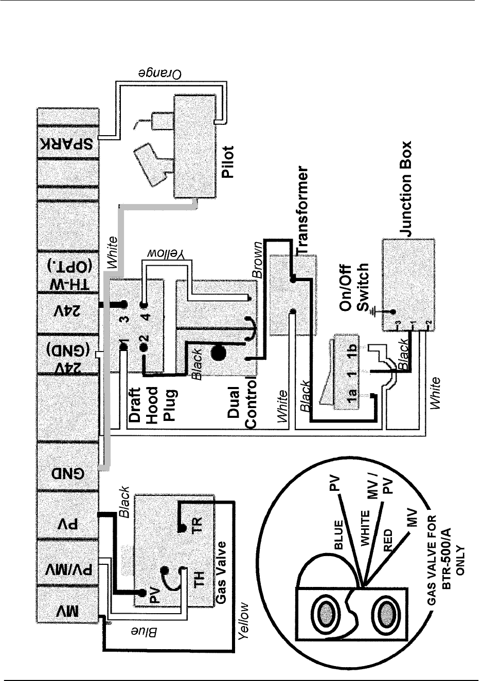
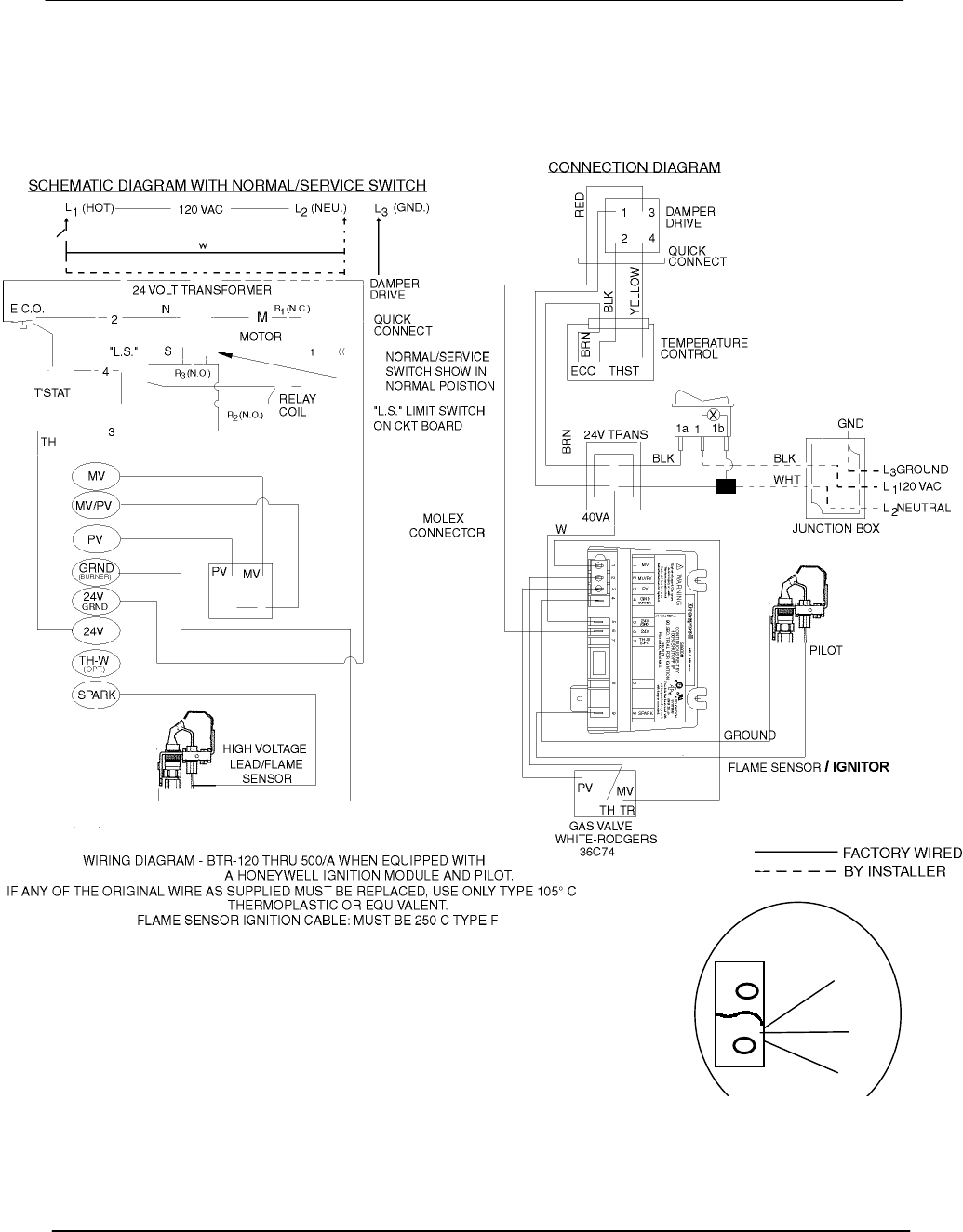
BTR WIRING DIAGRAM - NATURAL AND PROPANE GAS
Honeywell Ignition System (110 – 109 Series)
IF ANY OF THE ORIGINAL WIRE AS SUPPLIED MUST BE
REPLACED, USE ONLY TYPE 105° C THERMOPLASTIC OR
EQUIVALENT.
BLUE
WHITE
RED
PV
MV/
PV
MV
GAS VALVE FOR
BTR-500/A ONLY

BTRTANKTYPEHEATERS
SERVICE WORKBOOK
A.O. Smith Water Products Service Handbook
Irving, Texas ©2000 Training Department
43
GENERAL SERVICE CHART
CONDITION CAUSE SOLUTION
DAMPER OPENS NO POWER
TO IID MODULE . DAMPER NOT FULLY OPEN
. DEFECTIVE PROTECTOR
SWITCH
.EFFIKAL – REPLACE DAMPER CONTROL
ASSEMBLY
. REPLACE DAMPER
. REPLACE PC BOARD
PILOT LIGHTS, SPARKS
CONTINUOUSLY PILOT FLAME NOT PROVING SEE FLAME RECTIFICATION - STEP 16
HEATER WILL NOT IGNITE NOT PROVING PILOT
FLAME EXISTANCE
INTERRUPT 120 VAC POWER
. CHECK GROUND WIRE
ATTACHMENT
. CLEAN OR REPLACE PILOT
ASSEMBLY
PILOT GAS NOT COMPLETELY
INTERRUPTED AT END OF
HEATING CYCLE
. CHECK SUPPLY GAS PRESSURE
. REPLACE GAS VALVE
. THERMAL EXPANSION ADD THERMAL EXPANSION TANK
WEEPING TEMPERATURE
AND
PRESSURE RELIEF VALVE
. FAULTY VALVE REPLACE RELIEF VALVE
. EXCESSIVE WATER
TEMPERATURE
. CHECK WIRING
. REPLACE DUAL CONTROLLER
LARGE VOLUME WATER
RELIEF FROM T&P VALVE
. FAULTY RELIEF VALVE REPLACE RELIEF VALVE
PREMATURE TANK
LEAKAGE
CONDENSATION . INCREASE STORED WATER
TEMPERATURE AND CONFIRM
PROPERLY SIZED APPLICATION
CONTAMINATED AIR . REMOVE CONTAMINANTS.
. SUPPLY CLEAN COMBUSTION
AIR.
WATER HAMMER . ADD WATER HAMMER
ARRESTOR.
. REDUCE WATER PRESSURE.
. REMOVE UNNECESSARY CHECK
VALVES.
THERMAL EXPANSION ADD THERMAL EXPANSION TANK.
DEPLETED ANODES SCHEDULE ANODE CHECKS -
REPLACE AS NEEDED.
DAMPER WILL NOT OPEN BINDING SHAFT SUPPORT VENTING
SHAFT SPRING WEAK/BROKEN REPLACE DAMPER NON-EFFIKALS
DAMPER MOTOR REPLACE MOTOR EFFIKAL-REPLACE DAMPER
CONTROL ASSEMBLY
NO SPARK AT PILOT -
DAMPER FULLY OPEN
DAMPER ASSEMBLY REPLACE PC BOARD - SEE STEP 10
Services Switch may bypass problem until
replacement part is received. (EFFIKAL –
REPLACE DAMPER CONTROL ASSEMBLY
IID MODULE REPLACE IID STEP 12
SPARK CABLE REPLACE CABLE STEP 13

BTRTANKTYPEHEATERS
SERVICE WORKBOOK
A.O. Smith Water Products Service Handbook
Irving, Texas ©2000 Training Department
44
GENERAL QUESTIONS AND ANSWERS
Q. What changes caused series 106/107 and 108/109 to be implemented?
A. The 106 and 107 series units changed from the momentary push button to a slide
switch. The 108 and 109 series implemented a new main burner construction process. The
damper boards with service switch and new style main burners will automatically be
replacement parts for previous series heaters if parts are ordered.
Q. What is unique about the Canadian – BTRC – models vs. U.S. BTR models?
A. The Canadian models have different dimensions to meet Canadian code requirements.
Q: How much electrical power is required for a BTR water heater?
A: The BTR models draw approximately .7 Amps at 120VAC.
Q: The units require "leg kits" to meet National Sanitation Foundation standards. What are the
part numbers for these kits?
A: The BTR model heaters need AOS kit numbers:
BTR 120-400 (except BTR 197&198 series 100) = Part # 6570-0
BTR 197&198 Series 100 = Part # 6570-5
BTR 500 = Part # 6570-7
Q: When should BTRs be delimed?
Many variables affect the liming up process including:
water temperature - The amount of lime accumulation during the same period of time will be
nearly 2 times greater if water is stored at 140 degrees F than at 120 degrees F. A 180
degree setting will build up lime about seven times as fast as a 140 degree F setting.
volume of water - The more gallons flowing through the BTR, the more rapid the
accumulation.
hardness – The harder the water the faster lime build up occurs. 1 to 3.5 grains per gallon is
"soft", 3.5 to 7 grains per gallon is "moderate", 7 to 10.5 grains per gallon is "hard" and 10.5 +
grains per gallon is "very hard". (An aspirin is about 5 grains. One grain is equal to 17.1 parts
per million.)
A: Deliming should be done when a slight rumbling or popping sound is detected when the main
burners are on.
Q: What effect will lime build-up have on the BTR water heater?
A: One eighth inch of scale build-up may reduce efficiency as much as 22%; a 1/4 inch build-up,
as much as 38%.
A: Less efficient heat transfer means more bottom head expansion/contraction stress and
premature leakage.
A: Heavy build-up on the bottom head and bottom portion of the flue pipes leads to more heat
transfer at the top of the flues. This can lead to stacking or erratic thermostat operation.
Q: Anode rods provide additional protection against corrosion. When should these be
replaced?
A: When large gouges or pits appear in the anodes, replace them. It is recommended that
these be inspected every 6 months.
BTRTANKTYPEHEATERS
SERVICE WORKBOOK
A.O. Smith Water Products Service Handbook
Irving, Texas ©2000 Training Department
45
BTR MODELS 197 AND 198
Series 100-101
BTRTANKTYPEHEATERS
SERVICE WORKBOOK
A.O. Smith Water Products Service Handbook
Irving, Texas ©2000 Training Department
46
BTR MODELS 197 AND 198 (continued)
Series 100-101

BTRTANKTYPEHEATERS
SERVICE WORKBOOK
A.O. Smith Water Products Service Handbook
Irving, Texas ©2000 Training Department
47
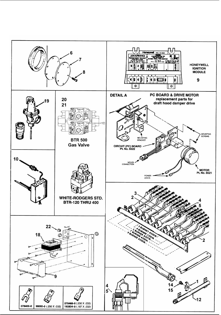
PARTS LIST for BTR Models 197 and 198 Series 100 & 101
Item Parts Description BTR 197 BTR 198
1 Bracket For Main Burner Orifice............... 098044(5) 098044(5)
2 Main Burner ............................................. 192322 192322
3 Main Burner w/Pilot Bracket..................... 193873-0 193873-0
4 Pilot Burner Natural ................................. 193314-0 193314-0
5 Pilot Burner Propane ............................... 193314-1 193314-1
6 Gasket ..................................................... 99036 99036
7 Pressure Plate ......................................... 99037 99037
8 Screws, Self Tapping............................... 69852 69852
9 Control, Ignition Module ........................... 193325 193325
10 Control, Dual w/ECO ............................... 192828 192828
11 Drafthood................................................. 192957-4 192957-4
12 Manifold................................................... 76244-2 76244-2
13 Instruction Manual ................................... 193927 193927
14 Main Burner Orifice Natural .....................76243-32 76243-32
15 Main Burner Orifice Propane.................... 76243-49 76243-49
16 Anode Rod............................................... 43817-38 (4) 43817-42 (4)
17 T & P Relief Valve ................................... 99465-7 99465-7
18 Transformer ............................................. 193444 193444
19 Inlet Tube ................................................ 192626 192626
20 Gas Valve Natural.................................... 192827-2 192827-2
21 Gas Valve Propane.................................. 192827-3 192827-3
22 Off/On Switch .......................................... 193243 193243
BTRTANKTYPEHEATERS
SERVICE WORKBOOK
A.O. Smith Water Products Service Handbook
Irving, Texas ©2000 Training Department
48
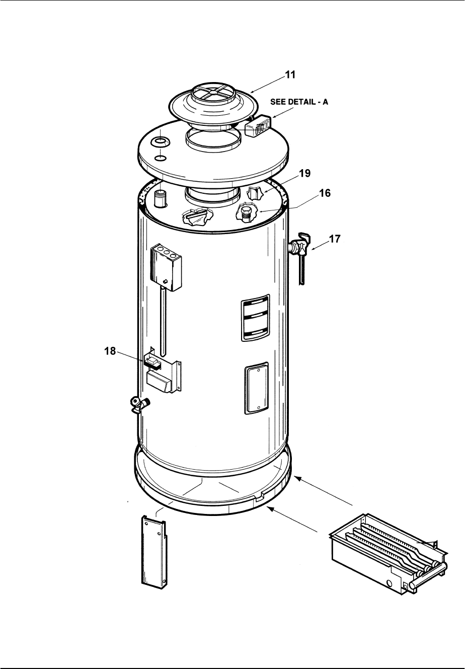
BTR MODELS 120 through 500
Series 104-105
BTRTANKTYPEHEATERS
SERVICE WORKBOOK
A.O. Smith Water Products Service Handbook
Irving, Texas ©2000 Training Department
49
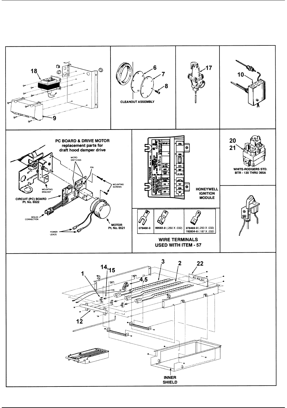
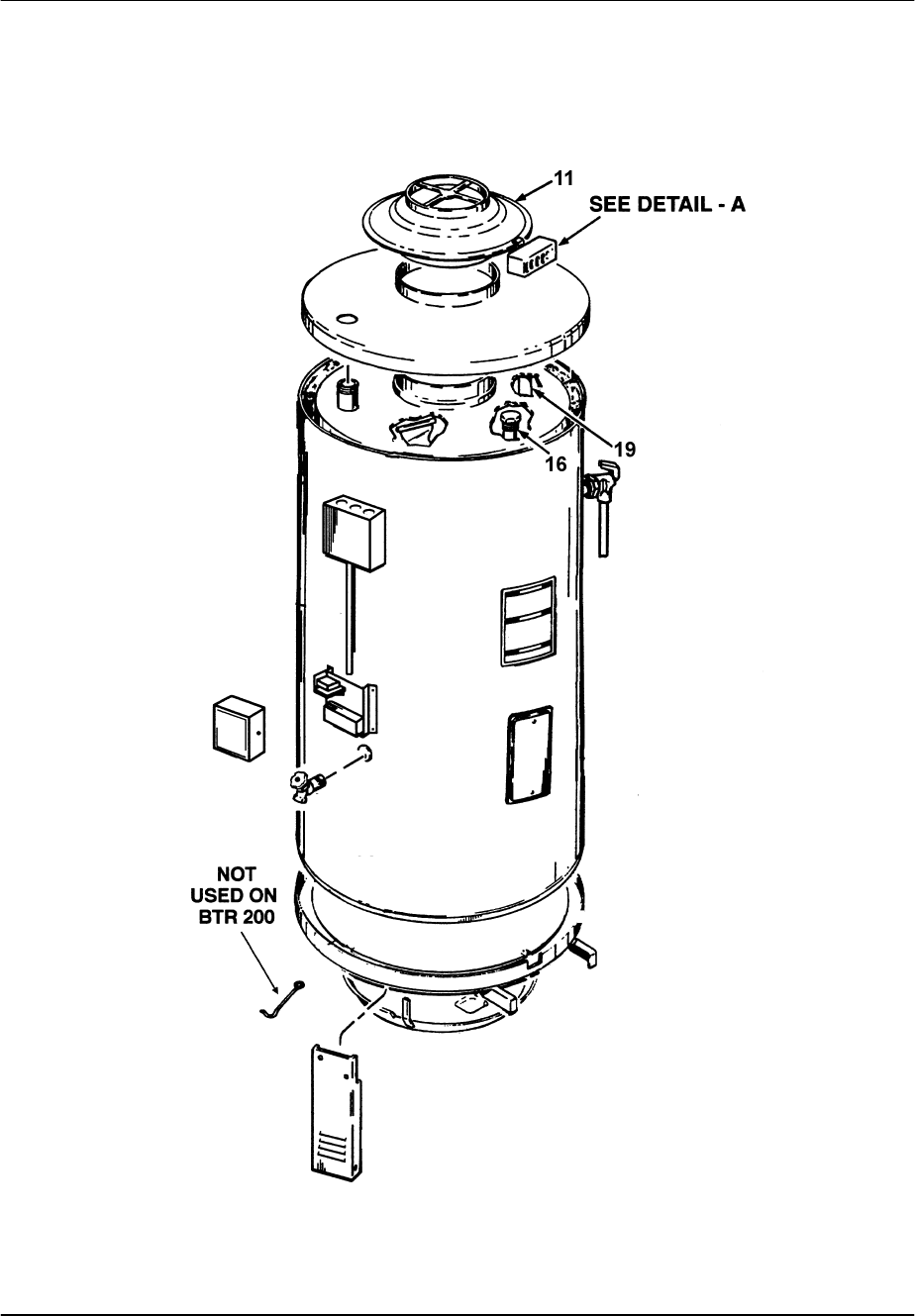
BTR MODELS 120 through 500 (continued)
Series 104-111

BTRTANKTYPEHEATERS
SERVICE WORKBOOK
A.O. Smith Water Products Service Handbook
Irving, Texas ©2000 Training Department
50
PARTS LIST FOR BTR Models 120 Through 500(A)
Series 104 Through 109 Series
(Series 106/107 have a service switch on Circuit Board 6522; Series 108/109 have new
main burner production method. Both parts will automatically be shipped
on 104 thru 109 series heaters.)
Item Parts Description BTR-120 BTR-154 BTR-180 BTR-199 BTR-200 BTR-250
1 Main Burner, Orifice Bracket 98044(3) 98044(3) 98044(5) 98044(5) 98044(5) 98044(5)
2 Main Burner 192322 98047 192322 192322 192322 098047
3 Main Burner w/Pilot Bracket 193873-0 193873-1 193873-0 193873-0 193873-0 193873-0
4 Pilot Burner, Natural 193314-0 193314-0 193314-0 193314-0 R 193314-4
5 Pilot Burner, Propane 193314-1 193314-1 193314-1 193314-1 193314-1 193314-3
6 Gasket, Cleanout 99036 99036 99036 99036 99036 99036
7 Pressure Plate, Cleanout 99037 99037 99037 99037 99037 99037
8 Screw, Self tapping, Cleanout 69852 69852 69852 69852 69852 69852
9 Control, Ignition Module 193325 193325 193325 193325 193325 193325
10 Control, Dual w/eco 192828 192828 192828 192828 192828 192828
11 Drafthood 193597-0 193597-1 192957-0 192957-0 192957-0 193287
11 Drafthood 110, 111 Series
12 Manifold 76244-0 76244-0 76244-2 76244-2 76244-2 76244-2
13 Instruction Manual, (not illustrated) 193927 193927 193927 193927 193927 193927
14 Main Burner Orifice, Natural 76243-32 76243-30 76243-35 76243-32 76243-32 76243-xx
15 Main Burner, Orifice, Propane 76243-49 76243-46 76243-51 76243-49 76243-48 76243-xx
16 Anode Rod 43817-38 (2) 43817-38 (2) 43817-38 (4) 43817-38 (4) 180618-42 (3) 180618-42 (4)
17 T & P Relief Valve 99465-7 99465-7 99465-7 99465-7 99465-7 192467
18 Transformer 193444 193444 193444 193444 193444 193444
19 Inlet Tube 193729 192626 193729 193729 192626 192626
20 Gas Valve, Natural 192827-2 192827-2 192827-2 192827-2 192827-2 192827-2
21 Gas Valve, LP 192827-3 192827-3 192827-3 192827-3 192827-3 192827-3
22 Off/On Switch 193243 193243 193243 193243 193243 193243
Item Parts Description BTR-251 BTR-275 BTR-305 BTR-365 BTR-400 BTR-500
1 Main Burner, Orifice Bracket 98044(7) 98044(5) 98044(7) 98044(9) 98044(9) 98044(9)
2 Main Burner 98047 98047 192322 192322 192322 192322
3 Main Burner w/Pilot Bracket 193873-0 193873-1 193873-0 193873-0 193873-0 193873-0
4 Pilot Burner, Natural 193314-4 193314-4 193314-4 193314-4 193314-4 193314-4
5 Pilot Burner, Propane 193314-3 193314-3 193314-3 193314-3 193314-3 193314-3
6 Gasket, Cleanout 99036 99036 99036 99036 99036 99036
7 Pressure Plate, Cleanout 99037 99037 99037 99037 99037 99037
8 Screw, Self tapping, Cleanout 69852 69852 69852 69852 69852 69852
9 Control, Ignition Module 193325 193325 193325 193325 193325 193325
10 Control, Dual w/eco 192828 192828 192828 192828 192828 192828
11 Drafthood 193287 193287 193287 193287 193287 193287
11 Drafthood 110, 111 Series
12 Manifold 76244-3 76244-2 76244-3 76244-4 76244-4 76244-4
13 Instruction Manual, (not illustrated) 193927 193927 193927 193927 193927 193927
14 Main Burner Orifice, Natural 76243-xx 76243-xx 76243-37 76243-32 76243-31 76243-28
15 Main Burner, Orifice, Propane 76243-xx 76243-xx 76243-48 76243-49 76243-48 76243-44
16 Anode Rod 43817-38 (4) 180618-42 (3) 43817-38 (4) 180618-42(4) 180618-42 (3) 180618-42 (4)
17 T & P Relief Valve 192467 192467 192467 192467 192467 192467
18 Transformer 193444 193444 193444 193444 193444 193444
19 Inlet Tube NA 192626 NA 192626 192626 192626
20 Gas Valve, Natural 192827-2 192827-2 192827-2 192827-2 192827-2 193366-0
21 Gas Valve, LP 192827-3 192827-3 192827-3 192827-3 192827-3 193366-1
22 Off/On Switch 193243 193243 193243 193243 193243 193243
∗For complete parts list call 1-800-433-2545

BTRTANKTYPEHEATERS
SERVICE WORKBOOK
A.O. Smith Water Products Service Handbook
Irving, Texas ©2000 Training Department
51
COMPONENT PART INFORMATION
NAME SPECIFICATIONS AOS PART NUMBERS
DUAL
CONTROLLER THERMOSTAT
120-180ORANGE, + 4O,5
O
DIFFERENTIAL,
LIQUID FILLED, ANTI-
STACKING
AOS # 192828
HIGH LIMIT
(ECO)
OPENS - 205OFIXED,
MANUAL
RESET BELOW 185O
GAS VALVE NATURAL GAS BTR 120-400;24VAC, 60hz,
.6A,.7” to 3.5” W.C.,
STEP OPEN
BTR 500; 24VAC, 60hz,
Dual Gas Valve,
STEP OPEN
AOS # 192827-2
AOS # 193366-0
PROPANE
GAS
BTR 120-400;
2.5 – 10” W.C.
STEP OPEN
BTR 500; 24VAC, 60hz,
Dual Gas Valve,
STEP OPEN
AOS # 192827-3
AOS # 193366-1
INTERMITENT
IGNITION
DEVICE
CONTROL
NATURAL GAS
AND
PROPANE
GAS
24 VAC, 50-60 HZ, .1A;
.7 MICROAMP SIGNAL
CONTINUOUS RETRIAL
AOS 193325
DAMPER COMPLETE
ASSEMBLY
SEE PARTS LIST
MOTOR 24 VAC, 60 HZ, 120 RPM,
5WATT
AOS #6521
P.C. BOARD
W/RELAY
Service Switch AOS #6522
TRANSFORMER 120 V PRIMARY, 24 VAC
SECONDARY,
40 VA, 50-60 HZ, CLASS 2
"B"
AOS #193444

BTRTANKTYPEHEATERS
SERVICE WORKBOOK
A.O. Smith Water Products Service Handbook
Irving, Texas © 1999 Training Department
52
BTR SERVICE CHECKLIST
(This service checklist may be photo copied to assist with BTR service call.)
This checklist is intended to aid the Service Agent in determining that the A.O. Smith
BTR Water Heater has been properly installed and is operating correctly. Because the
circumstances of each installation may vary greatly, it is not intended to be an all-
inclusive list of the problems that the Service Agent may encounter. Any item checked
"no" on this list should be thoroughly investigated and corrective action taken, if
required.
SERVICE AGENT INSTALLATION DATE
MODEL NUMBER SERVICE DATE
SERIAL NUMBER LOCATION ADDRESS
GAS TYPE - CHECK ONE
NATURAL PHONE( ) ___ - ____
PROPANE
I. Check Clearances (circle answer)
A. Are exterior clearances adequate? yes no
B. Are interior clearances adequate? yes no
Comments:
II. Check Makeup Air Requirements
A. Is the quantity of make-up air adequate per the National Fuel Gas Code? yes no
Comments:
B. Is the quality of make-up air adequate? yes no
Comments:
III. Gas Pressure (fill in blank)
A. Supply gas pressure inches of w.c.
B. Manifold gas pressure (main burner) inches of w.c.
Comments:
IV. Venting (check)
A. Properly sized per the National Fuel Gas Code? yes no
B. Does the installation have mechanically assisted venting? yes no
If so, is it operational? yes no
Comments:
V. WATER PIPING

BTRTANKTYPEHEATERS
SERVICE WORKBOOK
A.O. Smith Water Products Service Handbook
Irving, Texas © 1999 Training Department
53
Is the system properly sized? yes no
Is the system properly installed? yes no
Are there any water leaks? yes no
Does the installation have a recirculating system? yes no
If so, is it operational? yes no
VI. PROPER SEQUENCE OF OPERATION
During standby does damper close on standby? yes no
During standby is pilot flame off? yes no
On a call for heat does thermostat close? yes no
On a call for heat does damper open completely? yes no
Does sparking begin at pilot? yes no
Is pilot flame established? yes no
If so, does sparking stop? yes no
Does main burner ignite? yes no
Does the thermostat satisfy? yes no
Does damper close? yes no
Comments:
VII. SAFETY
A. Gas
Does pilot flame prove before main burner ignites? yes no
Does damper blade fully open before ignition sequence occurs? yes no
Is burner cover plate in place? yes no
Is burner floor shield in place? yes no
Does IID lockout occur after 30 sec. trial for ignition? (Propane models only) yes no
B. Water Temperature
Is the thermostat adjusted to the lowest acceptable temperature? yes no
Does the installation have a mixing valve? yes no
If so, is it operational? yes no
What is the outlet temperature of the mixing valve?
NOTE: (To minimize the risk of scalding, the manufacturer recommends storing water at 120°F.)
Is a properly rated temperature and pressure relief valve installed? yes no
C. Electrical
Is the 120 VAC electrical power supply properly wired? yes no
Are all the BTR control covers in place? yes no
Is the 120 VAC electrical power supply properly fused? yes no
D. Flammables
Are flammable materials located in the area of the water heater? yes no
Are flammable vapors located in the area of the water heater? yes no
Comments:
(This service checklist may be photo copied to assist with BTR service call.)

BTRTANKTYPEHEATERS
SERVICE WORKBOOK
A.O. Smith Water Products Service Handbook
Irving, Texas © 1999 Training Department
54
COMMENTS
Author: Terry Mulder
