A O Smith Btp 140 Owners Manual COF 60047 008.p65
BTP-140-140 thru 600-2500 to the manual d609056f-3add-48e6-b9b4-7062c513dad0
2015-01-05
: A-O-Smith A-O-Smith-Btp-140-140-Owners-Manual-162899 a-o-smith-btp-140-140-owners-manual-162899 a-o-smith pdf
Open the PDF directly: View PDF ![]() .
.
Page Count: 16
1
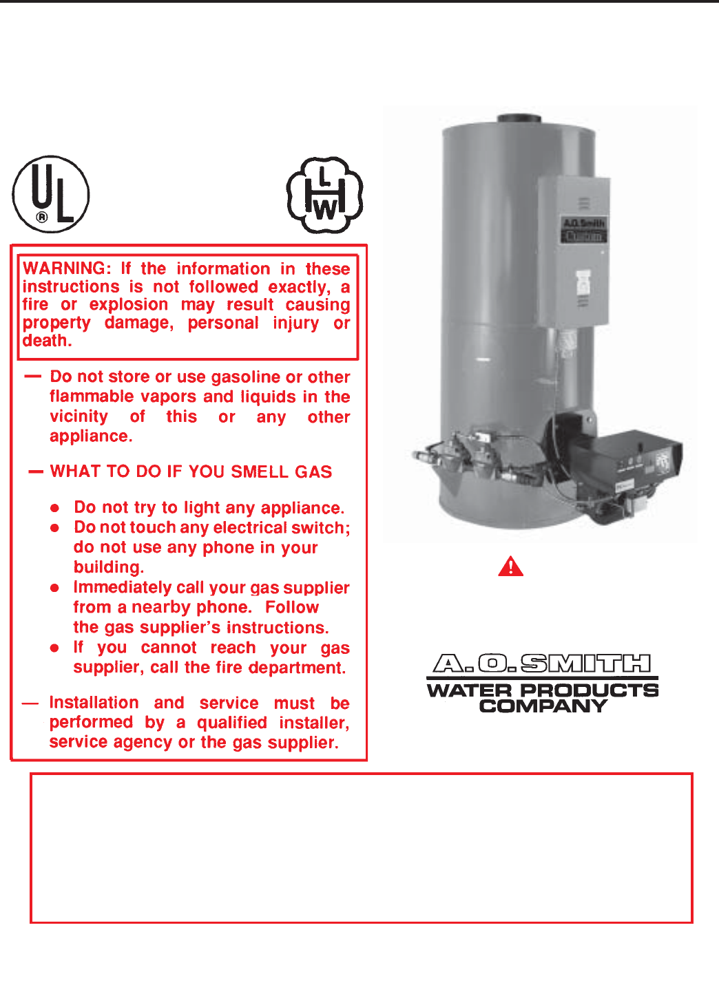
WARNING – PROPANE MODEL
Water heaters for propane gas are different from natural gas models. A natural gas heater will not function
safely on propane gas and no attempt should be made to convert a heater from natural gas to propane gas.
Propane gas must be used with great caution. It is highly explosive and heavier than air. It collects first in the
low areas making its odor difficult to detect. If propane gas is present or even suspected, do not attempt to
find the cause yourself. Ventilate the room, then call your gas supplier or service agent. Keep area clear until
a service agent has been called.
MODELS BTP-140-140 thru 600-2500
INCLUDING BTPD/BTPN/COF & COBT
COMMERCIAL GAS, OIL AND GAS/OIL TANK-TYPE WATER HEATERS
• INSTALLATION • OPERATION • SERVICE • MAINTENANCE • LIMITED WARRANTY
PLACE THESE INSTRUCTIONS ADJACENT TO HEATER AND
NOTIFY OWNER TO KEEP FOR FUTURE REFERENCE
PART NO. 60047-008 REV.6
PRINTED IN U.S.A. 3882 1100 SUPERSEDES 60047-008 REV.5
A DIVISION OF A.O. SMITH CORPORATION
RENTON, WASHINGTON
www.hotwater.com
CAUTION
TEXT PRINTED OR OUTLINED IN RED CONTAINS
INFORMATION RELATIVE TO YOUR SAFETY.
PLEASE READ THOUROUGHLY BEFORE USING
APPLIANCE.
CONSERVATIONIST®
ASME
2
FOREWORD
This manual is intended to be used in conjunction with other
literature provided with the heater. This includes power burner
and related gas control information. It is important that this manual
and the additional publications be reviewed in their entirety before
beginning any work.
The installation should be made in accordance with the regulations
of the local code authorities and utility companies, which pertain
to this type of water heating equipment.
MAKE SURE the fuel on which the heater will operate is the same
as that specified on the heater model and rating plate.
THESE HEATERS MUST NOT BE INSTALLED ON
COMBUSTIBLE FLOORS.
Instructions for periodic testing of various water heater safety
devices are included in section titled COMBUSTION
ARRANGEMENT REQUIREMENTS AND SERVICE
RECOMMENDATIONS.
In the absence of local codes, the installation must comply with
the instruction as outlined in the latest publication of ANSI booklet
NFPA-54/ANSI Z223.1 “NATIONAL FUEL GAS CODE”, NFPA No.
70 “NATIONAL ELECTRICAL CODE”, or Canadian Gas
Association booklet CAN 1-B149.1 or CAN 1-B149.2 for Canadian
Installations also be followed.
These manuals can be purchased from the American Gas
Association Laboratories, 8501 East Pleasant Valley Road,
Cleveland, OH 44131 or the National Fire Protection Association,
1 Batterymarch Park, Quincy, MA 02269-9101, or Canadian Gas
Association Labortories, 55 Scarsdale Road, Don Mills, Ontario,
Canada M3B 2R3.
TABLE OF CONTENTS
This manual is supplemented by the power burner manual. All information, including start-up and
maintenance relating to the burner, can be found in that manual.
PAGE
FOREWORD ................................................................................ 2
IDENTIFICATION ......................................................................... 2
GENERAL SAFETY INFORMATION ........................................... 3
Precautions ............................................................................. 3
Grounding Instructions ............................................................ 3
Improper Combustion .............................................................. 3
Liquid Petroleum Models ......................................................... 3
Extended Non-Use Periods (BTP Models Only) ..................... 3
Insulation Blankets .................................................................. 3
High Altitude Installations ........................................................ 3-4
FEATURES .................................................................................. 4
Water Temperature Control ..................................................... 4
INSTALLATION INSTRUCTIONS ................................................ 4
Required Ability ....................................................................... 4
Uncrating ................................................................................. 4-5
Locating the Heater ................................................................. 5
Leveling ................................................................................... 5
Clearances .............................................................................. 5
Air Requirements ..................................................................... 5-6
Thermal Expansion (Closed System) ...................................... 6
Venting .................................................................................... 6
Vent Connector........................................................................ 6
Barometric Draft Control Assembly ......................................... 6-7
Water Line Connections .......................................................... 7
Thermometers (Not Supplied) ................................................. 7
Relief Valve ............................................................................. 7
Gas Piping ............................................................................... 7-8
Purging .................................................................................... 8
Gas Meter Size (City Gases Only) .......................................... 8
Gas Pressure Regulator .......................................................... 8
Wiring ...................................................................................... 8-11
TWO UNIT MANIFOLD INSTALLATION ..................................... 11
OPERATION ................................................................................ 11
Important ................................................................................. 11
General .................................................................................... 11
Filling ....................................................................................... 11
Combustion Arrangement Requirements
And Service Recommendations .............................................. 11-12
MAINTENANCE ........................................................................... 12
General .................................................................................... 12
Flushing ................................................................................... 12
Draining ................................................................................... 12
Sediment Removal .................................................................. 12
Lime Scale Removal ............................................................... 12-13
Relief Valve ............................................................................. 13
Power Burner ........................................................................... 13-14
Cleaning Flues - COF & COBT Only ....................................... 14
Vent Systems .......................................................................... 14
Barometric Draft Control ......................................................... 14
TROUBLESHOOTING ................................................................. 14-15
Replacement Parts .................................................................. 15
LIMITED WARRANTY ................................................................. 16
PAGE
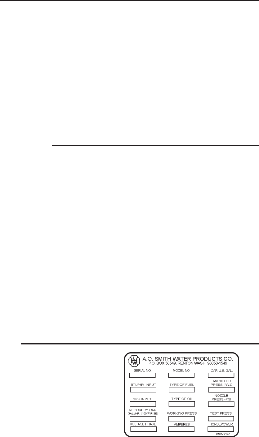
IDENTIFICATION
The heater and burner mounted identification plates provide
valuable information. When ordering parts or inquiring about a
unit, be sure to include serial number, model number and type of
fuel.

3
GENERAL SAFETY
INFORMATION
PRECAUTIONS
DO NOT USE THIS APPLIANCE IF ANY PART HAS BEEN
UNDERWATER. Immediately call a qualified service technician
to inspect the appliance and to replace any part of the control
system and any gas control which has been under water.
IF THE UNIT IS EXPOSED TO THE FOLLOWING, DO NOT
OPERATE HEATER UNTIL ALL CORRECTIVE STEPS HAVE
BEEN MADE BY A QUALIFIED SERVICEMAN.
1. EXTERNAL FIRE.
2. DAMAGE.
3. FIRING WITHOUT WATER.
4 SOOTING.
Heater must be protected from freezing downdrafts during
shutdown periods.
GROUNDING INSTRUCTIONS
This water heater must be grounded in accordance with the
National Electric Code and/or local codes. These must be followed
in all cases.
This water heater must be connected to a grounded metal,
permanent wiring system; or an equipment grounding conductor
must be run with the circuit conductors and connected to the
equipment grounding terminal or lead on the water heater.
CHEMICAL VAPOR CORROSION
WARNING
CORROSION OF THE FLUEWAYS AND VENT SYSTEM MAY
OCCUR IF AIR FOR COMBUSTION CONTAINS CERTAIN
CHEMICAL VAPORS WHICH BREAK DOWN INTO ACIDS AT
HIGH TEMPERATURE. SUCH CORROSION MAY RESULT IN
FAILURE AND RISK OF ASPHYXIATION.
Spray can propellants, cleaning solvents, refrigerator and air
conditioning refrigerants, swimming pool chemicals, calcium and
sodium chloride (water softener salt), waxes, and process
chemicals and typical compounds which are potentially corrosive.
Do not store products of this sort near the heater. Also, air which
is brought in contact with the heater should not contain any of
these chemicals. If necessary, uncontaminated air should be
obtained from remote or outside sources. The limited warranty is
voided when failure of water heater is due to a corrosive
atmosphere. (Refer to the limited warranty for complete terms
and conditions).
IMPROPER COMBUSTION
WARNING
ATTIC AND/OR EXHAUST FANS OPERATING ON THE
PREMISES WITH A WATER HEATER CAN RESULT IN CARBON
MONOXIDE POISONING AND DEATH.
OPERATING OF THESE FANS CAN PRODUCE A DOWN
DRAFT IN THE AREA OF THE WATER HEATER PREVENTING
THE PRODUCTS OF COMBUSTION FROM EXHAUSTING
THROUGH THE CHIMNEY OR VENT PIPE.
The venting of the water heater should be inspected by a qualified
service technician at the time of installation and periodically
thereafter to ensure a down-draft condition does not exist.
DO NOT OBSTRUCT THE FLOW OF COMBUSTION AND
VENTILATING AIR. ADEQUATE AIR FOR COMBUSTION AND
VENTILATION MUST BE PROVIDED FOR SAFE OPERATION.
LIQUID PETROLEUM MODELS
Water heaters for propane or liquefied petroleum gas (LPG) are
different from natural gas models. A natural gas heater will not
function safely on LP gas and no attempt should be made to
convert a heater from natural gas to LP gas.
LP gas must be used with great caution. It is highly explosive
and heavier than air. It collects first in the low areas making its
odor difficult to detect at nose level. If LP gas is present or even
suspected, do not attempt to find the cause yourself. Ventilate
the area, then call your gas supplier or service agent. Keep area
clear until a service call has been made.
The presence of LP gas may be difficult to detect. The use of a
propane gas detector is recommended.
Only trained LP professionals should conduct the required safety
checks in accordance with industry standards.
EXTENDED NON-USE PERIODS
WARNING
HYDROGEN GAS CAN BE PRODUCED IN A HOT WATER
SYSTEM SERVED BY THIS HEATER THAT HAS NOT BEEN
USED FOR A LONG PERIOD OF TIME (GENERALLY TWO
WEEKS OR MORE). HYDROGEN GAS IS EXTREMELY
FLAMMABLE. To reduce the risk of injury under these conditions,
it is recommended that a hot water faucet be opened for several
minutes before using any electrical appliance connected to the
hot water system. If hydrogen is present, there will probably be
an unusual sound such as air escaping through the pipe as the
water begins to flow. THERE SHOULD BE NO SMOKING OR
OPEN FLAME NEAR THE FAUCET AT THE TIME IT IS OPEN.
INSULATION BLANKETS
Insulation blankets available to the general public for external
use on gas water heaters are not approved for use on your A.O.
Smith water heater. The purpose of an insulation blanket is to
reduce the standby heat loss encountered with storage tank water
heaters. Your A.O. Smith water heater meets or exceeds the
ASHRAE/IES 90.1b-1992 standards with respect to insulation and
standby loss requirements making an insulation blanket
unnecessary.
WARNING
The application of an insulation blanket will void the warranty for
this water heater. Furthermore, the application of an insulation
blanket may interfere with the operation of this water heater,
possibly resulting in property damage, injury, or death.
HIGH ALTITUDE INSTALLATIONS
Your A.O. Smith water heater has been designed to operate at
altitudes above 2000 feet, provided that requirement was specified
at the time of order. The firing rate will be specified on the water
heater rating plate.
4
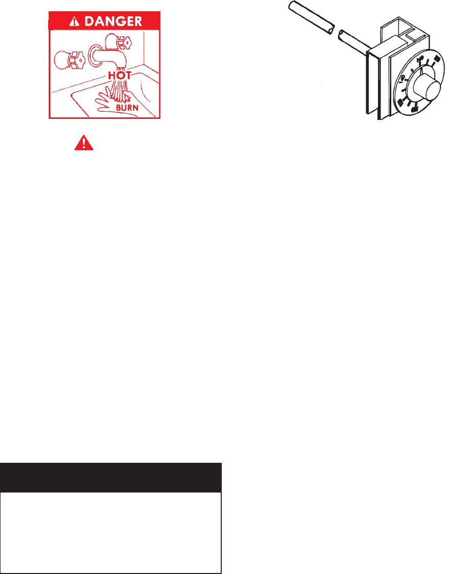
The water temperature is controlled by two thermostats. One
thermostat is located near the top of the tank and the other is in
the lower part of the tank. The upper thermostat must be set at
least 5°F higher than the lower thermostat. In the case where the
water heater has electronic thermostats, this differential has been
factory set and cannot be changed.
The thermostat temperature dials are accessible by opening the
control compartment cover.
FIGURE 1
A high limit switch interrupts the power burner operation should
the water temperature reach 200°F.
The high limit switch must be manually reset by depressing the
red button on the front of the control when water temperature
drops to about 180°F. The manual reset high limit can be found
inside the control compartment.
INSTALLATION INSTRUCTIONS
REQUIRED ABILITY
INSTALLATION OR SERVICE OF THIS WATER HEATER IS
REQUIRED TO BE PERFORMED BY AN AUTHORIZED A.O.
SMITH STARTUP AGENT. PLUMBING, AIR SUPPLY, VENTING,
GAS SUPPLY AND ELECTRICAL WORK ARE REQUIRED.
UNCRATING
The heater should be moved in the crate as close as possible to
the installation site. Depending upon size, shipping weights range
from about 1,300 to 4,500 pounds.
The installer should be guided by the instructions furnished with
the heater, local codes and utility company requirements.
Preference should be given to codes and requirements where
they differ from the heater furnished instructions.
Additional publications, which should guide the installer, include:
The latest version of the National Fuel Gas Code, ANSI Z223.1,
from American Gas Association Laboratories, 8501 East
Pleasant Valley Road, Cleveland, OH 44131.
In Canada – CGA No. B149 (latest version), from Canadian
Gas Association Laboratories, 55 Scarsdale Road, Don Mills,
Ontario, Canada M3B 2R3.
Code for the installation of Heat Producing Appliances (latest
version), from American Insurance Association, 85 John Street,
New York, NY 11038.
Note: Some gas utility companies derate the heating value of the
supplied gas at high elevations. Your authorized A.O. Smith Start-
Up Agent must adjust for actual heating valve of the gas at the
time of start-up.
FEATURES
WATER TEMPERATURE CONTROL
WARNING
THIS WATER HEATER IS EQUIPPED WITH AN ADJUSTABLE
THERMOSTAT TO CONTROL WATER TEMPERATURE. HOT
WATER TEMPERATURES REQUIRED FOR AUTOMATIC
DISHWASHER AND LAUNDRY USE CAN CAUSE SCALD
BURNS RESULTING IN SERIOUS PERSONAL INJURY AND/
OR DEATH. THE TEMPERATURE AT WHICH INJURY OCCURS
VARIES WITH THE PERSON’S AGE AND TIME OF EXPOSURE.
THE SLOWER RESPONSE TIME OF DISABLED PERSONS
INCREASES THE HAZARDS TO THEM. NEVER ALLOW SMALL
CHILDREN TO USE HOT WATER TAP, OR TO DRAW THEIR
OWN BATH WATER. NEVER LEAVE A CHILD OR DISABLED
PERSON UNATTENDED IN A BATHTUB OR SHOWER.
THE WATER HEATER SHOULD BE LOCATED IN AN AREA
WHERE THE GENERAL PUBLIC DOES NOT HAVE ACCESS
TO SET TEMPERATURES.
SETTING THE WATER HEATER TEMPERATURE AT 120°F WILL
REDUCE THE RISK OF SCALDS. Some states or provinces
require settings at specific lower temperatures.
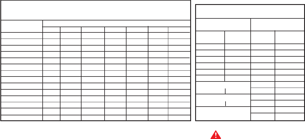
Below you will find listed the appropriate time-to-burn relationship
for normal adult skin. Short repeated heating cycles caused by
small hot water uses can cause temperatures at the point of use
to exceed the thermostat setting by up to 20°F (11°C). If you
experience this type of use, you should consider using lower
temperature settings to reduce scald hazards.
Temperature Time to Produce 2nd & 3rd
Setting Degree Burns on Adult Skin
180°F (82°C) Nearly Instantaneous
170°F (77°C) Nearly Instantaneous
160°F (71°C) About 1/2 Second
150°F (65°C) About 1-1/2 Seconds
140°F (60°C) Less than 5 Seconds
130°F (54°C) About 30 Seconds
120°F (49°C) More than 5 Minutes
Valves for reducing point-of-use temperature by mixing cold and
hot water are available. Also available are inexpensive devices
that attach to faucets to limit hot water temperatures. Contact a
licensed plumber or the local plumbing authority.

5
The latest version of the National Electrical Code, NFPA No.
70. In Canada refer to Canadian Electrical Code C 22.1, from
National Fire Protection Association, 1 Batterymarch Park,
Quicy, MA 02269-9101.
LOCATING THE HEATER
When installing the heater, consideration must be given to proper
location. Location selected should be as close to the stack or
chimney as practicable, with adequate air supply and as
centralized with the piping system as possible.
WARNING
THERE IS A RISK IN USING FUEL BURNING APPLIANCES
SUCH AS GAS WATER HEATERS IN ROOMS, GARAGES OR
OTHER AREAS WHERE GASOLINE, OTHER FLAMMABLE
LIQUIDS OR ENGINE DRIVEN EQUIPMENT OR VEHICLES ARE
STORED, OPERATED OR REPAIRED. FLAMMABLE VAPORS
ARE HEAVY AND TRAVEL ALONG THE FLOOR AND MAY BE
IGNITED BY THE HEATER’S IGNITION SYSTEM OR MAIN
BURNER FLAMES CAUSING FIRE OR EXPLOSION.
SOME LOCAL CODES PERMIT OPERATION OF GAS
APPLIANCES IF INSTALLED 18 INCHES OR MORE ABOVE THE
FLOOR. THIS MAY REDUCE THE RISK IF LOCATION IN SUCH
AN AREA CANNOT BE AVOIDED.
THE HEATER SHALL BE LOCATED OR PROTECTED SO IT IS
NOT SUBJECT TO PHYSICAL DAMAGE BY A MOVING
VEHICLE.
WARNING
FLAMMABLE ITEMS, PRESSURIZED CONTAINERS OR ANY
OTHER POTENTIAL FIRE HAZARDOUS ARTICLES MUST
NEVER BE PLACED ON OR ADJACENT TO THE HEATER.
OPEN CONTAINERS OF FLAMMABLE MATERIAL SHOULD
NOT BE STORED OR USED IN THE SAME ROOM WITH THE
HEATER.
THE HEATER MUST NOT BE LOCATED IN AN AREA WHERE
IT WILL BE SUBJECT TO FREEZING.
LOCATE HEATER NEAR A FLOOR DRAIN. THE HEATER
SHOULD BE LOCATED IN AN AREA WHERE LEAKAGE FROM
THE TANK OR CONNECTIONS WILL NOT RESULT IN DAMAGE
TO THE ADJACENT AREA OR TO LOWER FLOORS OF THE
STRUCTURE.
WHEN SUCH LOCATIONS CANNOT BE AVOIDED, A SUITABLE
METAL DRAIN PAN, ADEQUATELY DRAINED, SHOULD BE
INSTALLED UNDER THE HEATER. Such pans should be
fabricated with sides at least 2” deep, with length and width at
least 2” greater than the diameter of the heater and must be piped
to an adequate drain. The pan must not restrict combustion air
flow.
This unit must be installed on a non-combustible surface.
LEVELING
The heater shall be installed level. If it is necessary to adjust the
heater, use metal shims under the channel-type skid base.
CLEARANCES
Provide ample clearance on all sides for installation, adjustment
and replacement of burner, control components and other parts.
A clearance of 24” should be maintained from serviceable parts,
such as relief valve, power burner, thermostat and drain valve.
MINIMUM INSTALLATION CLEARANCES
BTP/BTPN/BTPD COF/COBT
FRONT - 18 Inches FRONT - 18 Inches
BACK - 0 Inches Back - 6 Inches
TOP - 5 Inches Top - 12 Inches
LEFT SIDE - 0 Inches LEFT SIDE - 6 Inches
RIGHT SIDE - 0 Inches RIGHT SIDE - 6 Inches
NOTE: If a chimney connector is used, the minimum clearance
from the top of the unit to the connector is 18 inches.
AIR REQUIREMENTS
WARNING
FOR SAFE OPERATION, AN AMPLE SUPPLY OF AIR MUST
BE PROVIDED FOR PROPER COMBUSTION AND
VENTILATION AIR IN ACCORDANCE WITH SECTION 5.3, AIR
FOR COMBUSTION AND VENTILATION, OF THE NATIONAL
FUEL GAS CODE, NFPA-54/ANSI Z223.1 OR APPLICABLE
PROVISIONS OF THE LOCAL BUILDING CODES. AN
INSUFFICIENT SUPPLY OF AIR WILL RESULT IN A YELLOW,
LUMINOUS BURNER FLAME, CAUSING CARBONING OR
SOOTING OF THE HEAT EXCHANGER AND CREATING A RISK
OF ASPHYXIATION. DO NOT OBSTRUCT THE FLOW OF
COMBUSTION AND VENTILATION AIR.
UNCONFINED SPACE
In buildings of conventional frame, brick or stone construction,
unconfined spaces may provide adequate air for combustion.
If the unconfined space is within a building of tight construction
(buildings using the following construction: weather stripping,
heavy insulation, caulking, vapor barrier, etc.), air for combustion,
ventilation and draft hood dilution must be obtained from outdoors
or spaces freely communicating with the outdoors. The installation
instructions for confined spaces in tightly constructed buildings
must be followed to ensure adequate air supply.
CONFINED SPACE
When drawing combustion and dilution air from inside a
conventionally constructed building to a confined space, such a
space shall be provided with two permanent openings, ONE IN
OR WITHIN 12 INCHES OF THE ENCLOSURE TOP AND ONE
IN OR WITHIN 12 INCHES OF THE ENCLOSURE BOTTOM.
Each opening shall have a free area of at least one square inch
per 1000 Btu/hr of the total input of all appliances in the enclosure,
but not less than 100 square inches.
If the confined space is within a building of tight construction, air
for combustion, ventilation and draft dilution must be obtained
from outdoors. When directly venting with the outdoors or venting
with the outdoors through vertical ducts, two permanent openings,
located in the aforementioned manner, shall be provided. Each
opening shall have a free area of not less than one square inch
per 4000 Btu/hr of the total input of all appliances in the enclosure.
If horizontal ducts are used, each opening shall have a free area
of not less than one square inch per 2000 Btu/hr of the total input
of all appliances in the enclosure.
Where an exhaust fan is installed in the same room with the boiler,
sufficient openings for air must be provided in the walls.
UNDERSIZED OPENINGS WILL CAUSE AIR TO BE DRAWN
INTO THE ROOM THROUGH THE CHIMNEY OR OTHER
6
UNDESIRABLE OPENINGS, CAUSING POOR COMBUSTION.
SOOTING MAY RESULT WITH AN INCREASED RISK OF
ASPHYXIATION.
THERMAL EXPANSION (CLOSED SYSTEM)
Thermal expansion occurs in any hot water system when system
water is heated or “recovered” during periods of non-use.
If the system is operated in an “open” condition such as being
connected directly to the city main, the volume of expanded water
generated during the recovery periods can be dissipated back
through the “open” connection to the city main so pressure cannot
increase.
However, once a back flow preventer is installed to isolate system
water from the public supply; or a pressure reducing valve is
installed to protect a water meter; or any device preventing flow
back into the cold water supply, the “open” condition becomes
“closed”. During periods of temperature recovery and no usage,
water expands and the pressure increases until a relief valve
opens spilling hot water.
A relief valve opening on pressure will flow small amounts of water,
whereas relieving on temperature releases large amounts of water.
Consult the section under “High Water Temperature” to determine
the cause of the relief valve to open due to temperature.
Since the water is not compressible, some provision must be made
for THERMAL EXPANSION to protect the system from excessive
pressures. Two options are:
1. Install an expansion tank properly and adequately sized for
the expanding volume of water.
2. Install a pressure relief valve in the cold water supply line having
a setting of at least 10lbs. below the system working pressure,
located at or near a suitable drain. This valve will open at
each heat cycle when there is no hot water demand on the
system.
Service problems or parts failure due to excessive pressure are
NOT covered under warranty.
The pressure and temperature relief valve supplied with the water
heater IS NOT considered to be protection against thermal
expansion.
VENTING
WARNING
THE INSTRUCTIONS IN THIS SECTION ON VENTING MUST
BE FOLLOWED TO AVOID CHOKED COMBUSTION OR
RECIRCULATION OF FLUE GASES. SUCH CONDITIONS
CAUSE SOOTING OR RISKS OF FIRE AND ASPHYXIATION.
Heater must be protected from freezing downdrafts during
shutdown periods.
Remove all soot or other obstructions from chimney, which will
retard free draft.
Venting materials used for this category 1 appliance must be in
accordance with the National Fuel Gas Code and all state and
local requirements.
NOTE: A NEGATIVE DRAFT MUST BE MAINTAINED IN VENT
PIPING (-0.02 to -0.06).
VENT CONNECTOR
The chimney vent connector diameter should be the same size
as the heater flue outlet, see table 1. A minimum rise of 1/4” per
foot of horizontal connector length must be maintained between
the heater and chimney opening, fig. 2. The connector length
should be kept as short as possible.
TABLE 1
BTP/BTPD/BTPN/COF/COBT FLUE OUTLET
INPUT (KBTUh) (INCHES)
140, 199 5
255, 270, 300 6
400 7
540, 600 8
720, 800, 1000 10
1250, 1500 12
1750, 2000 14
2250, 2500 16
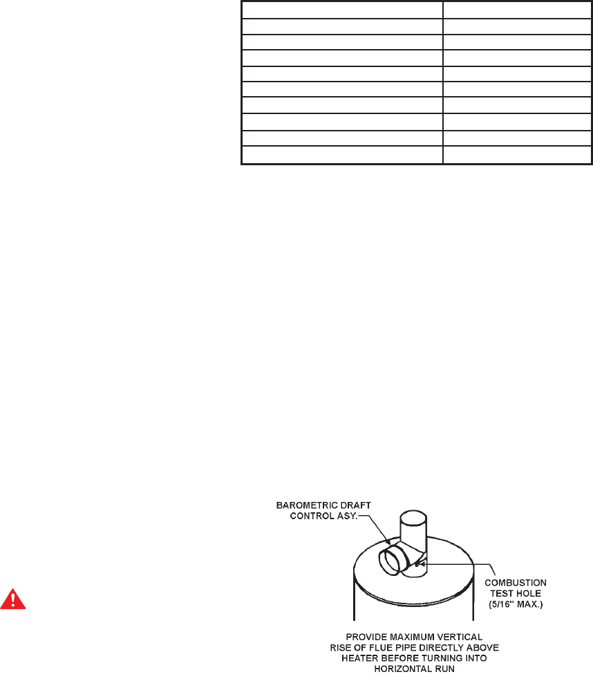
BAROMETRIC DRAFT CONTROL ASSEMBLY
A double-acting barometric draft control assembly is provided with
each unit. This assembly must be attached to the heater as shown
in figure 2. The direction in which the outlet to the draft control
assembly faces is arbitrary. This assembly must be fitted to the
jacket cover such that it is plumb and level to the ground. Fasten
the draft control assembly to the top cover using sheet metal
screws at three locations, or more, as required.
Refer to the instructions provided with the barometric damper for
complete installation requirements.
Dampers or other obstructions must not be installed between the
heater and the barometric draft control assembly.
Barometric draft control counterweights can be adjusted for
installation conditions by an authorized A.O. Smith Start-Up Agent.
Any readjustment must be by authorized A.O. Smith Start-Up
agent.
PROPER DRAFT CONTROLLER AND
VENT PIPE INSTALLATION - FIGURE 2
VENT CONNECTION
Vent connections must be made to an adequate stack or chimney.
Refer to the National Fuel Gas Code or to the vent pipe
manufacturer’s gas vent and chimney sizing table to properly
design and size the venting system. Refer to Table 2 for the vent
pipe size required for installation to the barometric draft control
assembly outlet.
7
Where an existing chimney or vent is to be used, be sure that the
chimney or vent has adequate capacity for the number and sizes
of gas appliances being vented through it. Inspect the chimney
or vent and remove all soot or other obstructions, which will retard
free draft.
Vent piping making horizontal runs must have a minimum upward
slope toward the chimney or vent of 1/4” per foot. Vent pipe
length should be kept as short as possible. Be sure that the vent
pipe does not extend beyond the inside wall of a chimney.
In venting systems, where a continuous or intermittent back
(positive) draft is found to exist, the cause must be determined
and corrected. In some cases, a special vent cap may be required.
WATER LINE CONNECTIONS
The water heater may be installed by itself, or with a separate
storage tank, on both single and two-temperature systems. When
used with a separate storage tank, the circulation may be either
by gravity or by means of a circulating pump.
SYSTEM CONNECTIONS
The system installation must conform to these instructions and to
the local code authority having jurisdiction. Good practice requires
that all heavy piping be supported.
THERMOMETERS (Not supplied)
Thermometers should be obtained and field installed as shown
in the installation diagrams.
Thermometers are installed in the system as a means of detecting
the temperature of the outlet water.
RELIEF VALVE
This water heater has been provided with an ASME rated pressure
and temperature relief valve.
In addition to the appliance relief valve, each remote storage tank,
which may be used in conjunction with this appliance, shall also
be installed with a properly sized, rated and approved temperature
(ANSI) and pressure (ASME) relief valve(s).
WARNING
THE PURPOSE OF A RELIEF VALVE IS TO AVOID EXCESSIVE
PRESSURE OR TEMPERATURE INTO THE STEAM RANGE,
WHICH MAY CAUSE SCALDING AT FIXTURES, TANK
EXPLOSIONS, SYSTEM OR HEATER DAMAGE. NO VALVE IS
TO BE PLACED BETWEEN THE RELIEF VALVE AND THE
TANK.
A DRAIN LINE MUST BE CONNECTED TO THE RELIEF VALVE
TO DIRECT DISCHARGE TO A SAFE LOCATION TO AVOID
SCALDING OR WATER DAMAGE. THIS LINE MUST NOT BE
REDUCED FROM THE SIZE OF THE VALVE OUTLET AND
MUST NOT CONTAIN VALVES, RESTRICTIONS NOR SHOULD
IT BE LOCATED IN FREEZING AREAS. DO NOT THREAD OR
CAP THE END OF THIS LINE. RESTRICTED OR BLOCKED
DISCHARGE WILL DEFEAT THE PURPOSE OF THE VALVE
AND IS UNSAFE. DISCHARGE LINE SHALL BE INSTALLED
TO ALLOW COMPLETE DRAINAGE OF BOTH THE VALVE AND
LINE.
Your local code authority may have other specific relief valve
requirements.
GAS PIPING
Contact your local gas service company to ensure that adequate
gas service is available and to review applicable installation codes
for your area.
Size the main gas line in accordance with Table 3. The figures
shown are for straight lengths of pipe at 0.3 in. w.c. pressure
drop, which is considered normal for low-pressure systems. Note
that fittings such as elbows and tees will add to the pipe pressure
drop.
Equivalent lengths of standard pipe in feet for listed fittings (add
below values to Table 3).
Install vent lines from main gas regulator and (if applicable) a
diaphragm gas valve. Vent line should be run to the outside of
the building, terminating clear of windows or fresh air intakes.
Outside terminal of vent should have a screen to prevent insects
from building nests in vent pipe. The vent should terminate in a
manner, which will preclude the possibility of water, snow, dirt or
other matter from entering the line.
CORRECTION FACTORS
Specific Gravity Pressure Drop
Other than 0.60 Other than 0.3
Specific Multplier Pressure Multiplier
Gravity Drop
0.50 1.10 0.1 0.577
0.60 1.00 0.2 0.815
0.70 0.926 0.3 1.00
0.80 0.867 0.4 1.16
0.90 0.817 0.6 1.42
1.00 0.775 0.8 1.64
Propane - Air 1.0 1.83
1.10 0.740 2.0 2.58
Propane 3.0 3.16
1.55 0.622 4.0 3.65
6.0 4.47
8.0 5.15
CAPACITY OF PIPE - NATURAL GAS IN CUBIC FEET PER HOUR
Maximum Based Upon Pressure Drop of 0.3” w.c. and Specific Gravity
of 0.60 and Maximum Gas Pressure of .5 psig.
Pipe Length Pipe Size - Inches (IPS)
In Feet 1 1 1/4 1 1/2 2 2 1/2 3 4
10 520 1050 1600 3050 4800 8500 17500
20 350 730 1100 2100 3300 5900 12000
30 285 590 890 1650 2700 4700 9700
40 245 500 760 1450 2300 4100 8300
50 215 440 670 1270 2000 3600 7400
60 195 400 610 1150 1850 3250 6800
70 180 370 560 1050 1700 3000 6200
80 170 350 530 990 1600 2800 5800
90 160 320 490 930 1500 2600 5400
100 150 305 460 870 1400 2500 5100
125 130 275 410 780 1250 2200 4500
150 120 250 380 710 1130 2000 4100
175 110 225 350 650 1050 1850 3800
200 100 210 320 610 980 1700 3500
NOTE: Use Multiplier at right for other specific gravities and pressure drops.
TABLE 2

8
TABLE 3
EQUIVALENT LENGTH OF FITTINGS IN FEET
Pipe Size (IPS) 1 1.25 1.5 2 2.5 3 4
Std. Tee through side 5.5 7.5 9.0 12.0 14.0 17.0 22.0
Std. E11 2.7 3.7 4.3 5.5 6.5 8.0 12.0
45°F E11 1.2 1.6 2.0 2.5 3.0 3.7 5.0
Plug Cock 3.0 4.0 5.5 7.5 9.0 12.0 16.0
WARNING
THE HEATER IS NOT INTENDED FOR OPERATION AT HIGHER
THAN 13.8” WATER COLUMN (1/2 POUND PER SQUARE INCH)
SUPPLY GAS PRESSURE. HIGHER GAS PRESSURE
REQUIRES SUPPLEMENTAL REDUCING SERVICE
REGULATION. EXPOSURE TO HIGHER GAS SUPPLY
PRESSURE MAY CAUSE DAMAGE TO THE GAS CONTROLS
WHICH COULD RESULT IN FIRE OR EXPLOSION. IF
OVERPRESSURE HAS OCCURRED SUCH AS THROUGH
IMPROPER TESTING OF GAS LINES OR EMERGENCY
MALFUNCTION OF THE SUPPLY SYSTEM, THE GAS VALVE
MUST BE CHECKED FOR SAFE OPERATION. MAKE SURE
THAT THE OUTSIDE VENTS ON THE SUPPLY REGULATORS
AND THE SAFETY VENT VALVES ARE PROTECTED AGAINST
BLOCKAGE. THESE ARE PARTS OF THE GAS SUPPLY
SYSTEM, NOT THE HEATER. VENT BLOCKAGE MAY OCCUR
DURING ICE STORMS.
IT IS IMPORTANT TO GUARD AGAINST GAS VALVE FOULING
FROM CONTAMINANTS IN THE GAS WAYS. SUCH FOULING
MAY CAUSE IMPROPER OPERATION, FIRE OR EXPLOSION.
IF COPPER SUPPLY LINES ARE USED THEY MUST BE
INTERNALLY TINNED AND CERTIFIED FOR GAS SERVICE.
BEFORE ATTACHING THE GAS LINE, BE SURE THAT ALL GAS
PIPE IS CLEANED ON THE INSIDE.
TO TRAP ANY DIRT OR FOREIGN MATERIAL IN THE GAS
SUPPLY LINE, A DIRT LEG (SOMETIMES CALLED A SEDIMENT
TRAP OR DRIP LEG) MUST BE INCORPORATED IN THE
PIPING. THE DIRT LEG MUST BE READILY ACCESSIBLE AND
NOT SUBJECT TO FREEZING CONDITIONS. INSTALL IN
ACCORDANCE WITH RECOMMENDATIONS OF SERVING GAS
SUPPLIERS. REFER TO THE NATIONAL FUEL GAS CODE.
To prevent damage, care must be taken not to apply too much
torque when attaching gas supply pipes to gas valve inlet.
Apply joint compounds (pipe dope) sparingly and only to the male
threads of pipe joints. Do not apply compound to the first two
threads. Use compounds resistant to the action of liquefied
petroleum gases.
DISCONNECT THE APPLIANCE AND ITS MANUAL GAS
SHUTOFF VALVE FROM THE GAS SUPPLY PIPING SYSTEM
DURING ANY SUPPLY PRESSURE TESTING EXCEEDING 1/2
PSIG. GAS SUPPLY LINE MUST BE CAPPED WHEN
DISCONNECTED FROM THE HEATER. FOR TEST
PRESSURES OF 1/2 PSIG OR LESS, THE APPLIANCE NEED
NOT BE DISCONNECTED, BUT MUST BE ISOLATED FROM
THE SUPPLY PRESSURE TEST BY CLOSING THE MANUAL
GAS SHUTOFF VALVE.
BEFORE PLACING THE HEATER IN OPERATION, CHECK FOR
GAS LEAKAGE. USE SOAP AND WATER SOLUTION OR
OTHER MATERIAL ACCEPTABLE FOR THE PURPOSE OF
LOCATING GAS LEAKS. DO NOT USE MATCHES, CANDLES,
FLAME OR OTHER SOURCES OF IGNITION FOR THIS
PURPOSE.
PURGING
Gas line purging is required with new piping or systems in which
air has entered.
CAUTION
PURGING SHOULD BE PERFORMED BY PERSONS
EXPERIENCED IN THIS TYPE GAS SERVICE. TO AVOID RISK
OF FIRE OR EXPLOSION, PURGE DISCHARGE MUST NOT
ENTER CONFINED AREAS OR SPACES WHERE IGNITION
CAN OCCUR. THE AREA MUST BE WELL VENTILATED AND
ALL SOURCES OF IGNITION MUST BE INACTIVATED OR
REMOVED.
GAS METER SIZE – CITY GASES ONLY
Be sure that the gas meter has sufficient capacity to supply the
full rated gas input of the water heater as well as the requirements
of all other gas fired equipment supplied by the meter. If gas
meter is too small, request the gas company to install a meter
having adequate capacity.
GAS PRESSURE REGULATOR
DO NOT SUBJECT COMBINATION GAS VALVE TO INLET GAS
PRESSURE OF MORE THAN 14 I.W.C. A SERVICE
REGULATOR IS NECESSARY IF HIGH GAS PRESSURES ARE
ENCOUNTERED.
The gas pressure regulator vent line must be vented to the
outside of the building.
POWER BURNER
For information relating to the power burner supplied with this
water heater, refer to the power burner manual provided.
LIFTING LUGS
This water heater is supplied with lifting lugs. Prior to lifting, insure
that the lugs are threaded into their receptacles as tight as
possible.
These lugs may be removed after installation. Sheet metal covers
are provided to cover the receptacle openings.
WIRING
The rating plate provides the electrical information needed to size
the water heater branch supply circuit.
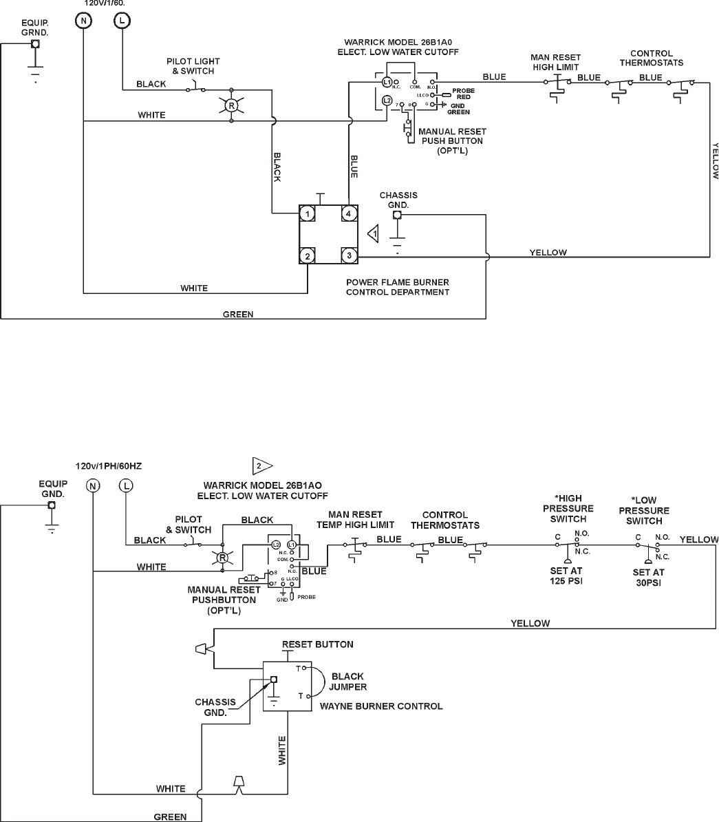
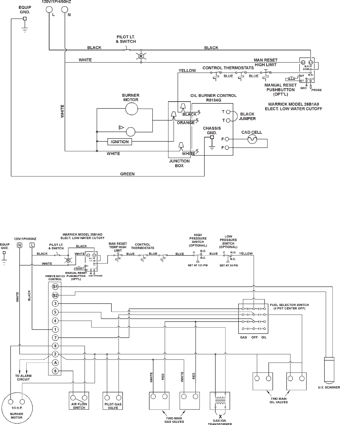
Typical water heater electrical diagrams are provided in this
manual (pages 9 and 10). The actual diagram, corresponding to
each water heater, is provided with each water heater, and may
differ from the diagrams shown in this manual.
The BTP unit burner is wired to the water heater control
compartment as shown in the following diagram. The electrical
service should be connected to the N & L Terminals located in
the control compartment. Ground from control compartment to
suitable ground.
All electrical work must be installed in accordance with the National
Electrical Code (latest version) and local requirements. AN
ELECTRICAL GROUND IS REQUIRED TO REDUCE THE RISK
9
TYPICAL WIRE DIAGRAM
BTP, 270 - 2,500 KBTUH
COF, 800 - 2,500 KBTUH
COBT, 400 - 2,500 KBTUH
TYPICAL WIRE DIAGRAM
BTP, 140 - 255 KBTUH
10
TYPICAL WIRE DIAGRAM
COF, 140 - 720 KBTUH
TYPICAL WIRE DIAGRAM
COBT, 140 - 300 KBTUH
11
OF ELECTRICAL SHOCK. DO NOT ENERGIZE THE BRANCH
CIRCUIT BEFORE THE HEATER TANK IS FILLED WITH
WATER.
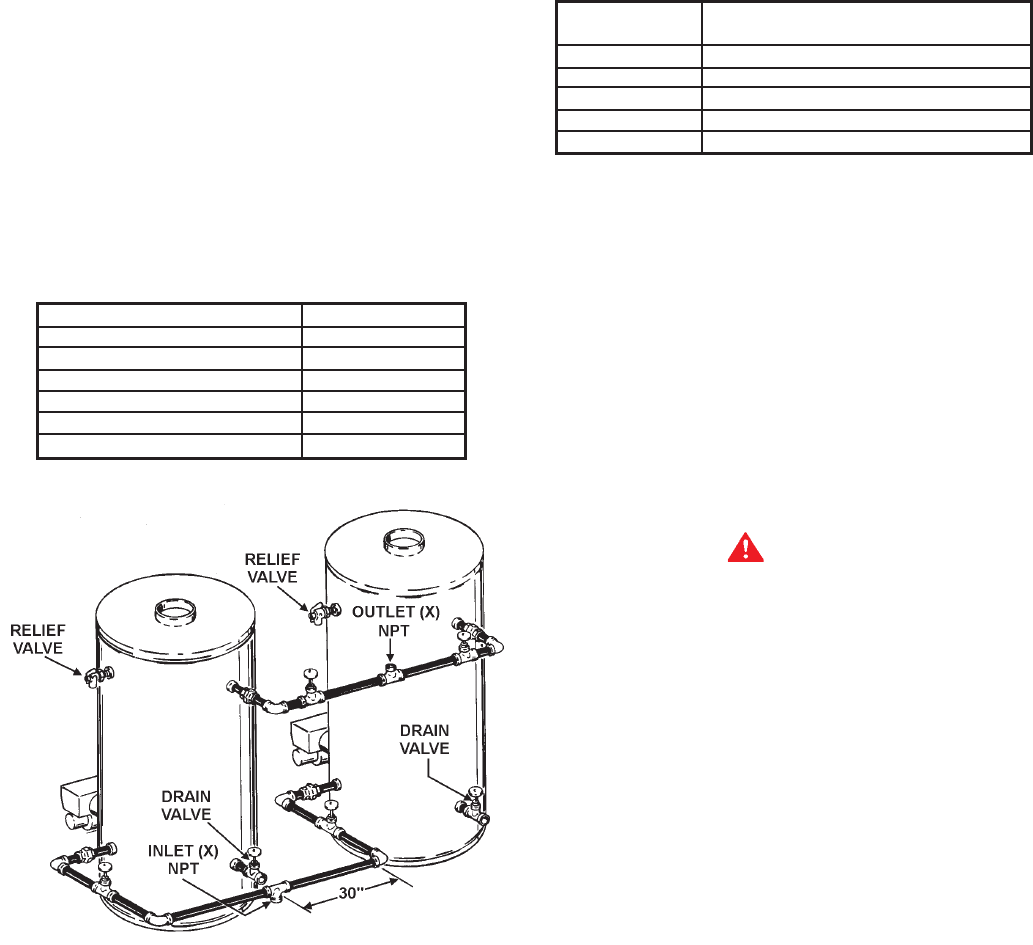
TWO UNIT MANIFOLD
INSTALLATION
Assure water flow balance of all units. Without this balance, the
full water heating and storage potential of the system cannot be
achieved. Otherwise, the units with the higher water flow may
have a shortened life.
Dimensions shown are for minimum space occupied by complete
assemblies. Service space in front of units must be included.
MODEL MANIFOLD SIZE
BTPD-85 2”
BTPN/BTP/COF/COBT - 140 2”
BTPN/BTP/COF/COBT - 200 2 1/2”
BTPN/BTP/COF/COBT - 300 2 1/2”
BTPN/BTP/COF/COBT - 400 3”
BTPN/BTP/COF/COBT - 600 3”
OPERATION
IMPORTANT
AUTHORIZED START-UP REQUIRED. Start-up by an A.O.
Smith Authorized BTP/BTPN/COF/COBT Start-Up Agent is
required on the models covered in this manual. Start-up and
Operation of the units covered by this manual by other than
an A.O. Smith Authorized BTP/BTPN/COF/COBT Start-Up
Agent will void the warranty.
If you have not already done so, contact your local A.O. Smith
Sales Representative or Authorized BTP/BTPN/COF/COBT Start-
Up Agent and set-up a date for the start-up service.
The Authorized Start-Up Agent will when they come out to start-
up the unit(s) complete one of the following forms for each unit
you have and submit it to A.O. Smith Water Products Company
to activate your warranty:
Start-Up Covering Models
Form No.
09063511 BTP Models, 140 - 255 kBTUH
09063510 BTP Models, 270 - 2500 kBTUH
09063512 COBT Models, 140 - 2500 kBTUH
09063514 COF Models, 140 - 2500 kBTUH
09063515 BTPN Models, 400 - 2000 kBTUH
The time to ask any questions you may have about your unit is
when the A.O. Smith Authorized BTP/COF/COBT Start-Up Agent
is there. Please do not hesitate to ask the agent any questions
which you may have regarding the units start-up, operation or
maintenance.
A MAINTENANCE section is included at the rear of this manual.
Any service required should be performed by an Authorized A.O.
Smith Service Agent.
GENERAL
NEVER OPERATE THE HEATER WITHOUT FIRST BEING
CERTAIN IT IS FILLED WITH WATER AND A TEMPERATURE
AND PRESSURE RELIEF VALVE IS INSTALLED IN THE RELIEF
VALVE OPENING OF THE HEATER.
CAUTION
Before proceeding with the operation of the unit make sure the
water heater and system are filled with water and all air is expelled.
FILLING
1. Close the heater drain valve by turning handle clockwise.
2. Open a nearby hot water faucet to permit the air in the system
to escape.
3. Fully open the cold water inlet pipe valve allowing the heater
and piping to be filled.
4. Close the hot water faucet as water starts to flow.
5. The heater is ready to be operated.
COMBUSTION ARRANGEMENT REQUIREMENTS
AND SERVICE RECOMMENDATIONS
1. In order to fire correctly, the burner requires an adequate supply
of combustion air. Ventilation to the boiler room should be
provided on the basis of one square inch of free air opening
for each 1000 BTU/HR input. This excludes the requirements
for any other fired equipment in the room. The boiler room
should not become excessively hot and under no
circumstances should be under negative pressure.
2. The burner must be set up initially and serviced at regular
intervals (suggested semi-annually) by a trained serviceman
using the proper instruments. During this semi-annual service,
primary safety devices should be tested under operating
conditions. Failure to routinely test primary safety devices may
cause hazards. Suggested test procedures are listed in the
following paragraphs. Failure to maintain the correct burner
settings may result in inefficient gas consumption, premature
wear of burner components, or explosion hazard.

12
3. The correct test instruments are:
•CO
2 indicator or 02 analyzer
• CO indicator
• Stack thermometer
• Draft gauge or inclined manometer
• U-tube manometer or calibrated 0-10” and 0-35” w.c.
pressure gauge
• Combination volt/ammeter.
Suggested safety device test procedures are:
A. While heater is operating, turn valve, main burner and pilot
gas line manual gas cocks to the OFF position. Burner should
shutdown within 3-4 seconds and lockout on flame failure,
requiring reset of the flame safeguard device.
B. While heater is operating, lower the setting of each of (2)
operating thermostats (one at a time). During this setting
change, the burner should shutdown when the called for
temperature is less than the temperature indicated on the
thermometer. Restore the settings to original values and burner
should restart.
Should any of the above operating test fail, replace the involved
component.
MAINTENANCE
GENERAL
Water heater maintenance includes periodic tank flushing and
cleaning, and removal of lime scale. The power burner should
be inspected and adjusted to maintain proper combustion. Refer
to the following table. A periodic inspection of the venting system
should be made. Where used, the water heating system
circulating pump should be oiled.
KEEP APPLIANCE AREA CLEAR AND FREE FROM
COMBUSTIBLE MATERIALS, GASOLINE AND OTHER
FLAMMABLE VAPORS AND LIQUIDS.
FLUSHING
1. Turn off the heater electrical disconnect switch.
• For convenience, the switch on the outside of the control
compartment can be used.
2. Open the drain valve and allow water to flow until it runs clean.
3. Close the drain valve when finished flushing.
4. Turn on the heater electrical disconnect switch.
MAINTENANCE SCHEDULE
Component Operation Interval Required
Flushing Monthly
Sediment
Tank Removal Semi-Annually
Lime Scale UN•LIME®
Removal As Required Delimer
Relief Valve Inspect Semi-Annually
Power Burner SAE No. 20
Motor(1) Inspect Quarterly non-detergent
motor oil
Power Burner Combustion
and Ignition Inspection Semi-Annually test kit &
Device(2) test
specifications
Main Burner Check Flame Annually
Flue Baffle
Pipe(3) Cleaning As Required Wire Brush
Vent System
and Barometric Inspect Semi-Annually Draft Gauge
Damper
(1) If furnished with oiling provisions
(2) If flange gasket is damaged, it must be repaired.
(3) COF and COBT Only.
DRAINING
The heater must be drained if it is to be shut down or exposed to
freezing temperatures. Maintenance and service procedures may
also require draining the heater.
1. Tun off the heater electrical disconnect switch.
2. Close the cold water inlet valve to heater.
3. Open a nearby hot water faucet to vent the system.
4. Open the heater drain valve.
5. If the heater is being drained for an extended shutdown, it is
suggested the drain valve be left open during this period.
• Follow FILLING instructions when restoring hot water service
SEDIMENT REMOVAL
Waterborne impurities consist of fine particles of soil and sand
which settle out and form a layer of sediment on the bottom of the
tank.
For convenience, sediment removal and lime scale removal
should be performed at the same time.
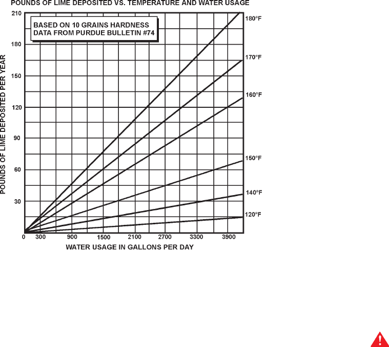
LIME SCALE REMOVAL
The amount of calcium (lime) released from water is indirect
proportion to water temperature and usage. The higher the water
temperature or water usage, the more lime deposits are dropped
out of the water. This is the lime scale which forms in pipes, heaters
and on cooking utensils.
13
Lime accumulation not only reduces the life of the equipment but
also reduces efficiency of the heater and increases fuel
consumption.
The usage of water softening equipment greatly reduces the
hardness of the water. However, this equipment does not always
remove all of the hardness (lime). For this reason it is
recommended that a regular schedule for deliming be maintained.
The depth of lime build-up should be measured periodically.
Heaters will have about 3” of lime build-up when the level of lime
has reached the bottom of the cleanout opening or about 1” of
lime build-up if it has reached the drain valve opening. A schedule
for deliming should be set-up; based on the amount of time it
would take for a 1” build-up of lime.
Example 1 = Initial inspection, after 1 year, shows 1/2” of lime
accumulation. Therefore, the heater can be
delimed once a year.
Example 2 = Initial inspection, after 1 year, shows 2” of lime
accumulation. Therefore, the heater should be
delimed every 3 months.
Following are the instructions for performing some of the
recommended maintenance. Power burner inspection and
adjustment should be performed by a competent technician.
Heater failure due to excessive lime build-up voids the warranty.
Sediment and lime scale removal may be accomplished through
the cleanout opening furnished on the heater. The heater must
be drained, see DRAINING, before removing cleanout cover on
tank.
To dissolve and remove the more stubborn mineral deposits, A.O.
Smith UN•LIME Professional Delimer should be used.
A. O. Smith UN-LIME Delimer is an easy to handle patented food
grade acid formulated specifically for lime scale removal from all
types of water using equipment. Available in 1 gallon (part no.
4763) and 5 gallon (part no. 4813) sizes. Hydrochloric acids are
not recommended for use on glass-lined tanks.
A. O. Smith Form no. 4800, entitled, “Why, When and How”,
describes tank cleaning methods and materials. UN•LIME and
the booklet may be obtained through your A. O. Smith dealer or
distributor.
To clean heater through cleanout opening, proceed as follows:
1. Turn off water inlet valve, the heater electrical disconnect switch
and open drain valve.
2. Remove outer cover plate from lower side of heater jacket.
3. Remove plug from cleanout opening.
• Place a short pipe nipple into the tank to extend beyond
the heater jacket.
4. Remove lime, scale and sediment using care not to damage
the glass coatings inside the tank.
5. Remove the nipple.
6. Replace cleanout plug.
7. Follow filling instructions when restoring hot water service..
8. Check for water leakage and correct as necessary.
9. Replace outer jacket cover plate.
RELIEF VALVE
At least twice a year, the temperature and pressure relief valve
should be checked to ensure that it is in operating condition. To
check the relief valve, lift the lever at the end of the valve several
times. The valve should seat properly and operate freely.
CAUTION
BEFORE MANUALLY OPERATING THE VALVE, MAKE SURE
THAT A DRAIN LINE HAS BEEN ATTACHED TO THE VALVE
TO DIRECT THE DISCHARGE TO AN OPEN DRAIN. FAILURE
TO TAKE THIS PRECAUTION COULD MEAN CONTACT WITH
EXTREMELY HOT WATER PASSING OUT OF THE VALVE
DURING THIS CHECKING OPERATION.
If the temperature and pressure relief valve on the heater
discharges periodically or continuously, it may be due to the
thermal expansion of water in a closed water supply system, or it
may be due to a faulty relief valve.
Thermal expansion is the normal response of water when it is
heated. In a closed system, thermal expansion will cause the
system pressure to increase until the relief valve actuation
pressure is equaled. Then, the relief valve will open, allowing
some water to escape slightly lowering the pressure. (See
THERMAL EXPANSION Section of pages 5 and 6).
Contact your water supplier or local plumbing inspector on how
to control this situation.
ABOVE ALL, DO NOT PLUG THE TEMPERATURE AND
PRESSURE RELIEF VALVE. THIS IS NOT A SOLUTION AND
CAN CREATE A HAZARDOUS SITUATION.
POWER BURNER
KEEP THE AREA AROUND THE BURNER CLEAR AND FREE
OF COMBUSTIBLE MATERIALS, GASOLINE OR OTHER
FLAMMABLE LIQUIDS OR VAPORS. DO NOT OBSTRUCT
14
BURNER AIR OPENINGS OR VENTILATION GRILLES FOR
COMBUSTION AIR. REMOVE LINT ACCUMULATION FROM
AIR INTAKE GRILL.
At least annually, contact a qualified service agency for burner
cleaning and other routine maintenance.
CLEANING FLUES-COF & COBT ONLY
The following describes how to gain access to the tank flues for
cleaning if necessary.
1. Turn off the heater electrical disconnect switch.
• The switch on the outside of the control compartment
may be used.
2. Remove the vent connector from on top the heater.
3. Remove the jacket top from the heater by taking out the screws
and lifting it off.
• The insulating pad should then be lifted out.
4. Take out the screws holding the flue gas collector top to the
tank and lift off.
5. The flue baffles may now be removed by lifting out.
• The flue baffles are flexible enough to bend for removal
within headroom.
6. Using a wire brush, remove soot from flue passages in heater
tank.
CAUTION
While cleaning tank flue passages, care must be taken that brush
does not come in contact with the combustion chamber lining as
damage could occur.
• If burner flue collector flange gaskets are damaged, replace.
VENT SYSTEMS
Examine the vent system every six months for obstruction and/or
deterioration of vent piping. Remove any soot or obstructions and
replace damaged vent piping.
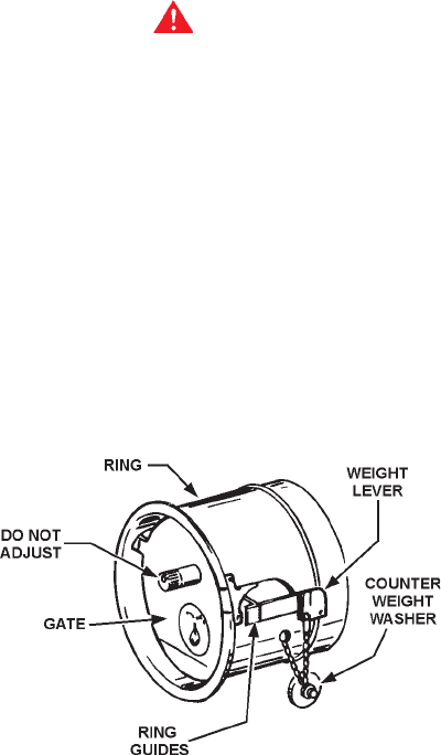
BAROMETRIC DRAFT CONTROL
The heater is equipped with a double acting barometric draft
control. The damper gate must pivot freely in the ring guides.
FIGURE 3
To test gate for operation, gently tap gate and observe. DO NOT
OIL.
The red solid fuel tabs supplied with the draft regulator must be
removed (See instructions supplied with Draft Regulator).
TROUBLESHOOTING
NOT ENOUGH OR NO HOT WATER
1. Be certain the electrical disconnect switch serving the water
heater is in the ON position.
• The outside of the control compartment and the power burner
housing also have switches.
2. Check the fuses
• The electrical disconnect switch usually contains fuses.
3. The capacity of the heater may have been exceeded by a large
demand for hot water.
• Large demands require a recovery period to restore water
temperature.
4. Colder incoming water temperature will lengthen the time
required to heat water to the desired temperature.
• If the heater was installed when incoming water temperature
was warm, colder water creates the effect of less hot water.
5. Look for hot water wastage and leaking or open hot water
faucets.
6. Sediment or lime scale may be affecting water heater operation.
Refer to MAINTENANCE for details.
7. Heater or burner may be dirty.
• Clean all heater flue pipes and flue connector, see
MAINTENANCE.
• Have burner properly cleaned and readjusted.
8. Burner may not be firing at proper rate.
• Check gas pressure, see burner manufacturer’s instruction
manual.
9. Burner fan wheel may be dirty.
10.Draft regulator may be stuck.
• Check to see if vane swings freely. Clean, if vane is stuck.
11.Reset button or burner flame safeguard primary control has
operated.
WATER IS TOO HOT
1. Water temperature control may be set too high.
2. If lowering the control setting does not reduce the water
temperature, contact your dealer.

15
WATER HEATER MAKES NOISE
1. Sediment or lime scale accumulations cause noises when the
heater is operating.
• The sounds are normal, however, the tank bottom should
be cleaned. Refer to MAINTENANCE for details.
2. Some of the electrical components of the water heater make
sounds, which are normal.
• Contacts click or snap as the heater starts and stops.
• Transformers often hum.
WATER LEAKAGE IS SUSPECTED
1. Check to see if the water heater drain valve is tightly closed.
Also check the cleanout-opening plug for leakage.
2. The apparent leakage may be condensation, which forms on
cool surfaces of the heater and piping.
3. If the outlet of the relief valve is leaking it may represent:
• Excessive water pressure.
• Excessive water temperature.
• Faulty relief valve.
Excessive water pressure is the most common cause of relief
valve leakage. It is often caused by a “closed system”. If a
check valve is in the inlet system it will not permit the expanded
hot water volume to equalize pressure with the main. The
relief valve must release this water or the water heater or
plumbing system will be damaged.
When such a condition is encountered, local codes or
inspection agency should be consulted to determine which
system is acceptable in your area. These may consist of:
• Installation of a second relief valve with lower setting than
the primary relief valve.
• An expansion tank of suitable size and pressure rating and
provision to avoid water logging.
REPLACEMENT PARTS
Replacement parts may be ordered through authorized servicers
or distributors, refer to your local Yellow Pages for where to call
or contact A. O. Smith Water Products Company, 5621 W. 115th
Street, Alsip, Illinois, 60803, 1-800-433-2545. When ordering
parts, be sure to state the quantity, part number and description
of the item including the complete model and serial number as it
appears on the product. Refer to the parts list for more information.
REPLACEMENT PARTS
For additional troubleshooting information, refer to the power
burner manual.

16
CERTIFIED FACTORY START - UP REQUIRED
To activate your warranty, contact your local sales representative or Authorized Start-up Agent to arrange for a FREE Certified Start-up.
A.O. Smith Corporation, the warrantor, extends the following LIMITED WARRANTY to the owner of this water heater.
1. THE TANK
If the glass lined tank in this water heater shall prove upon examination by the warrantor to have leaked due to natural corrosion from potable water
therein, during the first THREE years after initial installation, the warrantor will at its option, provide a replacement A. O. Smith water heater of
equivalent size and current model, less burner and controls. Some government agencies are requiring energy efficient standards for water
heaters. In the event regulations prohibit sale of a model of equivalent size and construction, A. O. Smith will provide a model which complies with
the regulations of your area, in which case the consumer will be charged the difference in price between the like replacement and the energy
efficient model required. The warranty on the replacement water heater will be limited to the unexpired term of the original warranty.
2. ALL OTHER PARTS
If within ONE year after initial installation of this water heater, any part or portion shall prove upon examination by the warrantor to be defective in
material or workmanship, the warrantor will repair such part or portion at its option.
3. CONDITIONS AND EXCEPTIONS
This warranty shall apply only if a certified factory start-up was performed and if the water heater is installed in accordance with local plumbing and
building codes, ordinances and regulations, the printed instructions provided with it and good industry practices. In addition, a temperature and
pressure relief valve, approved by the American Society of Mechanical Engineers, must have been installed.
a) This warranty shall apply only when the heater is used:
(1) at temperatures not exceeding the maximum setting of its thermostat;
(2) at water pressure not exceeding the working pressure shown on the water heater;
(3) when operated free from the damaging effects of uncontrolled water hammer;
(4) when filled with potable water, free to circulate at all times and the tank free of damaging water sediment or scaled deposits;
(5) in a non-corrosive and not-contaminated atmosphere;
(6) in its original installation location;
(7) with factory approved anode(s) installed;
(8) in the United States, its territories or possessions, and Canada.
b) Any accident to the water heater, any misuse, abuse (including freezing) or alteration of it, any operation of it in a modified
form, or any attempt to repair tank leaks will void this warranty.
c) This warranty is void if a device acting as a backflow prevention device (check valves etc.) is installed in the cold water
supply the heater is connected to, unless an effective method of controlling thermal expansion is also installed at the
heater(s) and operational at all times. The relief valve installed on the heater is not an acceptable method.
4. SERVICE AND REPAIR EXPENSES
Under the limited warranty the warrantor will provide only a replacement water heater or part thereof. The owner is responsible for all other costs.
Such costs may include but are not limited to:
a) Labor charges for service removal, repair or reinstallation of the water heater or any component part;
b) Shipping, delivery, handling, and administrative charges for forwarding the new heater or replacement part from the nearest
distributor and returning the claimed defective heater or part to such distributor.
c) All cost necessary or incidental for any material and/or permits required for installation of the replacement heater or part.
5. LIMITATIONS ON IMPLIED WARRANTIES
Implied warranties, including the warranty of merchantability imposed on the sale of this heater under state law are limited to one (1) year duration
for the heater or any of its parts. Some states do not allow limitation on how long an implied warranty lasts, so the above limitation may not apply
to you.
6. CLAIM PROCEDURE
Any claim under the warranty should be initiated with the dealer who sold the heater, or with any other dealer handling the warrantor’s products.
If this is not practicable, the owner should contact:
U.S. Customers Canadian Customers
AO Smith Corporation A.O. Smith Enterprises Ltd.
5621 W. 115th Street P.O. Box 310-768 Erie Street
Alsip, IL 60803 Stratford, Ontario N5A-6T3
Telephone: 1-800-323-2636 Telephone: (519) 271-5800
a) The warrantor will only honor replacement with identical or similar water heater or parts thereof, which are manufactured or
distributed by the warrantor.
b) Dealer replacements are made subject to in-warranty validation by warrantor.
7. DISCLAIMERS
NO OTHER EXPRESS WARRANTY HAS BEEN OR WILL BE MADE IN BEHALF OF THE WARRANTOR WITH RESPECT TO THE HEATER
OR THE INSTALLATION, OPERATION, REPAIR OR REPLACEMENT OF THE HEATER. THE WARRANTOR SHALL NOT BE RESPONSIBLE
FOR WATER DAMAGE, LOSS OF USE OF THE UNIT, INCONVENIENCE, LOSS OR DAMAGE TO PERSONAL PROPERTY OR OTHER
CONSEQUENTIAL DAMAGE. THE WARRANTOR SHALL NOT BE LIABLE BY VIRTUE OF THIS WARRANTY OR OTHERWISE FOR DAMAGE
TO ANY PERSONS OR PROPERTY, WHETHER DIRECT OR INDIRECT, AND WHETHER ARISING IN CONTRACT OR IN TORT.
a) Some states do not allow the exclusion or limitation of the incidental or consequential damage, so the above limitations or exclusions may
not apply to you
b) This warranty gives you specific legal rights, and you may also have other rights, which may vary, from state to state.
Fill in the following for your own reference. KEEP IT. Registration is not a condition of warranty. The model and serial number are found on the
heater’s rating plate.
Model No. _____________________ Serial No. ______________________________________ Date Installed ___________________
Dealer’s Name __________________________________________________________________________________________________________
Dealer’s Address __________________________________________________________________Phone Number _________________________
City and State _____________________________________________________________________ Zip _________________________________
KEEP THIS WARRANTY POSTED ADJACENT TO THE HEATER FOR FUTURE REFERENCE.
Model BTP/BTPD/BTPN/COF/COBT Limited Warranty
