A O Smith Dse 5 Thru 120 Owners Manual
DSE-5 THRU DSE-120 to the manual 58794cfb-d8ae-44d5-bff0-13b2fb6a3d17
2015-01-05
: A-O-Smith A-O-Smith-Dse-5-Thru-Dse-120-Owners-Manual-162967 a-o-smith-dse-5-thru-dse-120-owners-manual-162967 a-o-smith pdf
Open the PDF directly: View PDF ![]() .
.
Page Count: 24
1
• Installation • Operation • Maintenance • Checklist • Limited Warranty
CAUTION
TEXT PRINTED OR OUTLINED IN RED CONTAINS
INFORMATION RELATIVE TO YOUR SAFETY. PLEASE READ
THOROUGHLY BEFORE INSTALLING AND USING THIS
APPLIANCE.
KEEP THIS MANUAL WITH THE HEATER FOR FUTURE REFERENCE.
WHENEVER MAINTENANCE ADJUSTMENTS OR SERVICE IS REQUIRED.
PART NO. 60047-004 REV.6
SUPERSEDES PART NO. 60047-004 REV.5
A DIVISION OF A.O.SMITH CORPORATION
RENTON, WASHINGTON
www.hotwater.com
Dura-Power Electric Models
DSE-5 THRU DSE-120 COMMERCIAL WATER HEATERS
PRINTED IN U.S.A. 700
2
STANDARD BTU/ 30° 40° 50° 60° 70° 80° 90° 100° 110° 120° 130° 140°
KW INPUT HOUR
3 10,239 41 31 24 20 17 15 13 12 11 10 10 9
6 20,478 82 62 49 41 35 31 27 25 22 21 19 18
9 30,717 123 92 74 62 53 46 41 37 34 31 28 26
12 40,956 164 123 98 82 70 61 55 49 45 41 38 35
15 51,195 205 154 123 102 88 77 68 61 56 51 47 44
18 61,434 246 184 148 123 105 92 82 74 67 62 57 53
24 81,912 328 246 197 164 140 123 109 98 90 82 76 70
30 102,390 410 308 246 205 176 154 137 123 112 103 95 88
36 122,868 492 369 295 246 211 184 164 148 134 123 113 105
45 153,585 615 461 369 307 263 230 205 184 168 154 142 132
54 184,302 738 554 443 359 316 277 246 221 201 185 170 158
60** 204,780 819 615 492 410 351 307 273 246 223 205 189 176
75** 255,975 1025 768 615 512 439 384 341 307 279 256 236 219
90** 307,170 1229 922 738 615 527 461 410 369 335 307 284 263
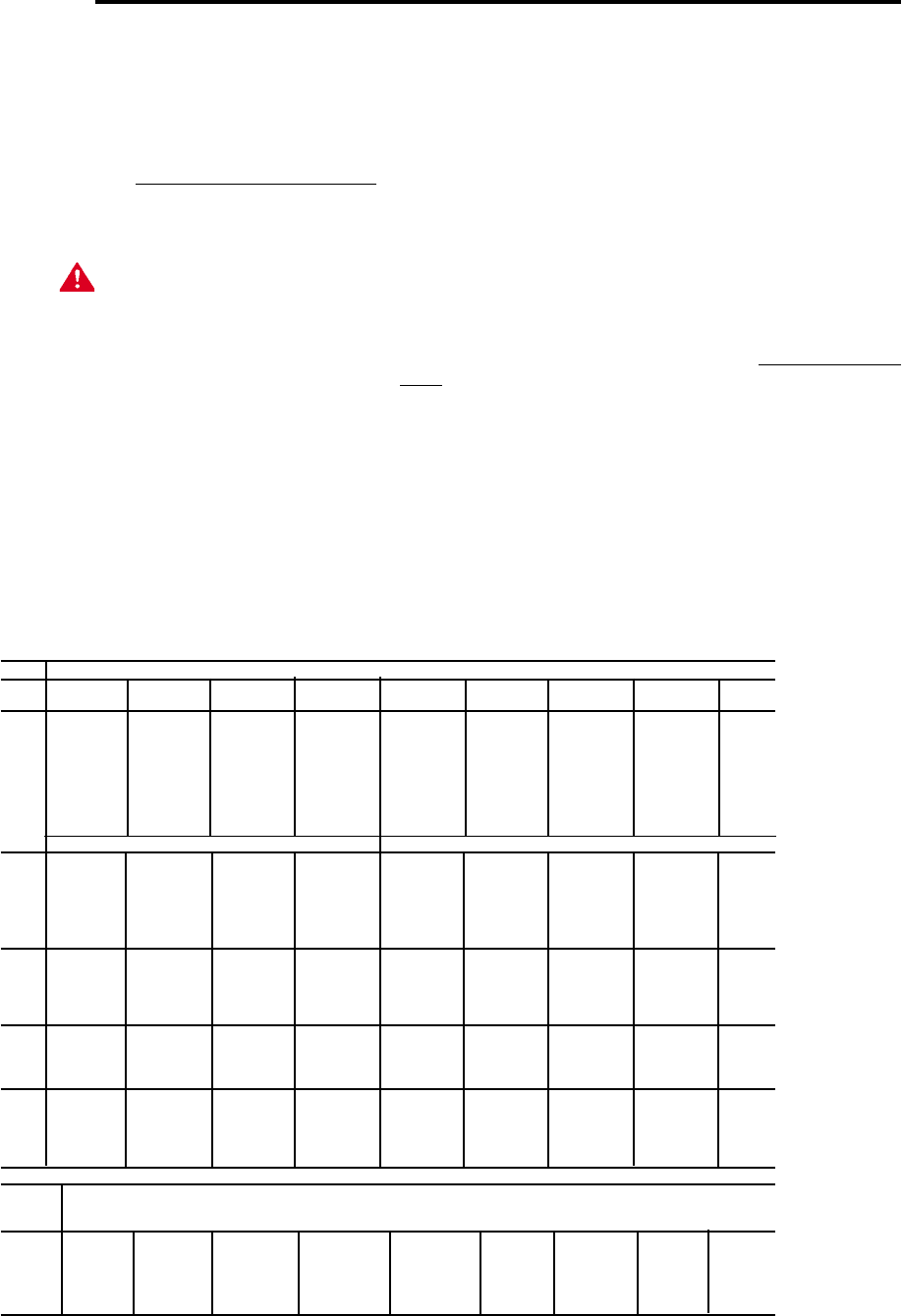
* Figured at 1KW (3413 Btu) = 4.1 Gallons at 100°F temperature rise.
To determine recovery rate per minute, divide recovery rate per hour by 60.
NSF ratings may be obtained by multiplying above figures by 0.98.
**Available on 50 gallon models or larger.
RECOVERY CAPACITY
RECOVERY RATE IN GALLONS PER HOUR *
Temperature Rise °F
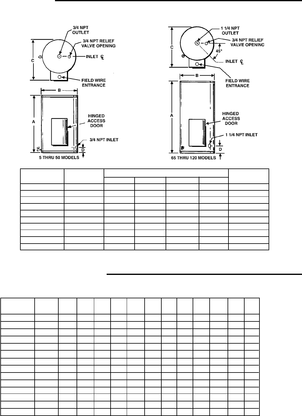
DIMENSIONS
Tank Capacity Maximum All Dimensions in Inches Approx. Ship
in Gallons KW Input A B C D Wt.Lbs.
5 3 20 /12 16 1/4 21 1/2 5 1/4 82
10 6 26 1/4 18 3/4 24 5 1/4 106
20 18 27 1/4 20 1/2 27 5 3/4 130
30 24 35 3/4 20 1/2 27 5 3/4 150
40 36 45 3/4 20 1/2 27 5 3/4 190
50 90 54 3/4 20 1/2 27 5 3/4 221
65 90 50 1/2 24 1/2 30 1/4 7 267
80 90 49 1/4 26 1/2 32 1/4 7 285
100 90 58 1/4 26 1/2 32 1/4 7 354
119 90 63 1/4 28 33 3/4 7 1/2 420
3
CONTENTS PAGE
ROUGH-IN-DIMENSIONS ...................................... 2
RECOVERY CAPACITY ....................................... 2
FOREWORD ......................................................... 3
APPROVALS ....................................................... 3
MODEL & RATING PLATE .................................... 3
GETTING TO KNOW YOUR WATER HEATER ...... 4
GENERAL SAFETY INFORMATION
Insulation Blankets .............................................. 5
External Damage ................................................. 5
INSTALLATION
Required Ability ................................................... 5
General ................................................................ 5
Location ............................................................... 5
Connections ........................................................ 6
Relief Devices ..................................................... 6
Temperature Limiting Control ............................... 6
Hydrogen Gas .................................................... 6
PIPING DIAGRAMS .............................................. 7-12
ELECTRICAL
General ................................................................ 13
Branch Circuit...................................................... 13
PAGE
Amperage Table/Overcurrent Protection........ 14
Heater Circuits ................................................ 14
Control Circuit ................................................. 14
Power Circuit .................................................. 14
Wiring Diagram ................................................ 15-17
OPERATION
General............................................................ 17
Filling ................................................................ 17
Start Up ........................................................... 17
Temperature Regulation .................................. 17-18
Draining ........................................................... 18
MAINTENANCE
General............................................................ 18
Flushing ........................................................... 18
Sediment Removal........................................... 18
Lime Scale Removal ........................................ 18-19
Checklist .......................................................... 19-20
Replacement Parts .......................................... 20
LEAKAGE CHECKPOINTS ............................... 21
LIMITED WARRANTY ...................................... 22
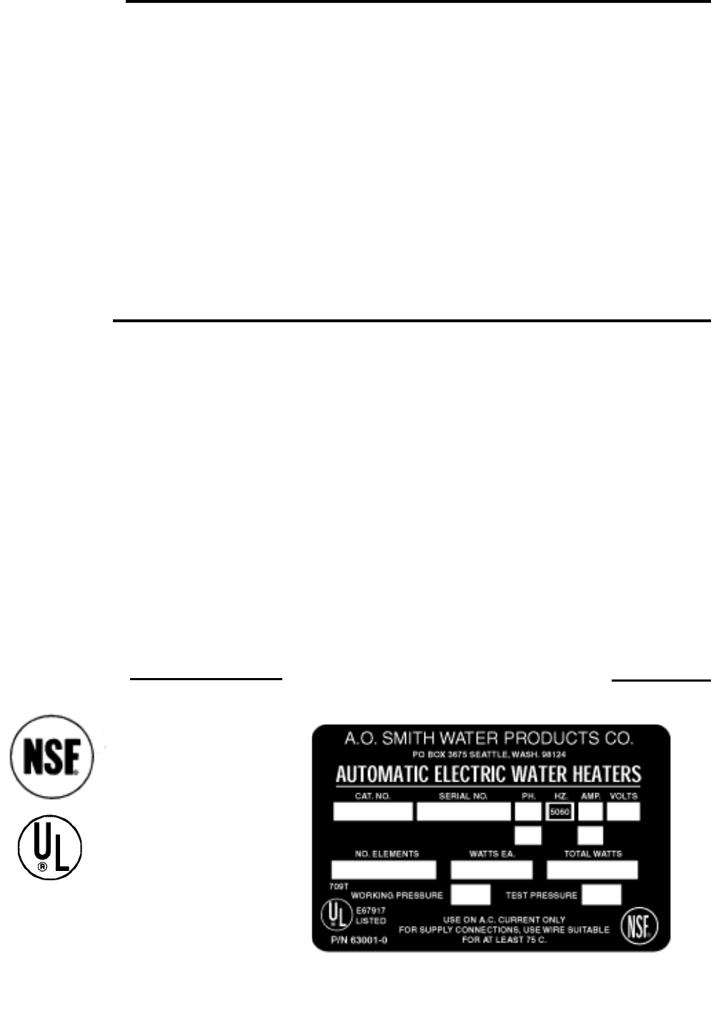
APPROVALS
All models bear the
National Sanitation
Foundation seal of
approval.
MODEL & RATING PLATE
ASME
All models are
listed
by Underwriters’
Laboratories, Inc.
125 PSI Working Pressure
(65 thru 120 Gallons)
150 PSI Working Pressure
(5 thru 50 Gallons)
FOREWORD
Detailed installation diagrams are in this manual. These
diagrams will serve to provide the installer with a reference for
the materials and method of piping suggested. IT IS
NECESSARY THAT ALL WATER PIPING AND THE ELECTRICAL
WIRING BE INSTALLED AND CONNECTED AS SHOWN IN THE
DIAGRAMS.
Particular attention should be given to the installation of
thermometers at the locations indicated in the diagrams as
these are necessary for checking the operation of the heater.
In addition to these instructions, the equipment shall be installed
in accordance with those installation regulations in force in the
local area where installation is to be made. Authorities having
jurisdiction shall be consulted before installations are made.
BE SURE TO TURN OFF POWER WHEN WORKING ON OR
NEAR THE ELECTRICAL SYSTEM OF THE HEATER. NEVER
TOUCH ELECTRICAL COMPONENTS WITH WET HANDS OR
WHEN STANDING IN WATER. WHEN REPLACING FUSES
ALWAYS USE THE CORRECT SIZE FOR THE CIRCUIT. SEE
PAGE 14.
DO NOT TEST ELECTRICAL SYSTEM BEFORE HEATER IS
FILLED WITH WATER, FOLLOW START UP PROCEDURE ON
PAGE 17.
The principal components of the heater are identified on page
4. The model and rating plate on page 3 interprets certain
markings into useful information. Both of these references
should be used to identify the heater, its components and
optional equipment.

4
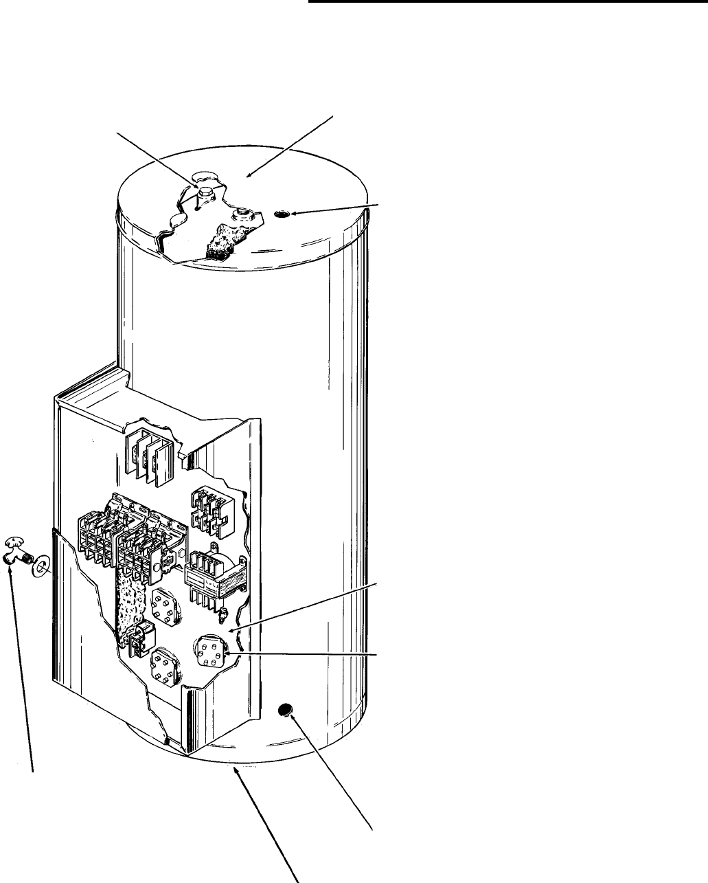
GETTING TO KNOW YOUR WATER HEATER
Below is an illustration of the water
heater with its features called out. The
text of this manual will refer to the items
shown.
FIGURE 1

5
GENERAL SAFETY
INFORMATION
INSULATION BLANKETS
Insulation blankets available to the general public for external
use on electric water heaters are not approved for use on your
A.O. Smith water heater. The purpose of an insulation blanket
is to reduce the standby heat loss encountered with storage tank
water heaters. Your A.O. Smith water heater meets or exceeds
the National Appliance Energy Conservation Act standards with
respect to insulation and standby loss requirements, making
an insulation blanket unnecessary.
WARNING
Should you choose to apply an insulation blanket to this heater,
you should follow these instructions (See Figure 1 for
identification of components mentioned below). Failure to follow
these instructions can result in fire, asphyxiation, serious
personal injury or death.
1. DO NOT COVER THE JUNCTION BOX EXTERNAL WIRING,
THERMOSTATS OR HEATING ELEMENTS ON ELECTRIC
WATER HEATER.
2. DO NOT COVER THE TEMPERATURE-PRESSURE RELIEF
VALVE.
3. DO NOT COVER OPERATING INSTRUCTIONS,
INSTALLATION OR SAFETY RELATED LABELS.
.
4. DO OBTAIN NEW WARNING AND INSTRUCTION LABELS
FROM A.O. SMITH FOR PLACEMENT ON THE BLANKET
DIRECTLY OVER THE EXISTING LABELS.
5. WATER AND/OR CONDENSATE CAN COLLECT IN AN
INSULATION BLANKET. A.O. SMITH WILL NOT BE LIABLE
FOR ANY RUST OR CORROSION DAMAGE CAUSED BY
THE INSTALLATION OF INSULATION BLANKETS.
WARNING
FAILURE TO FOLLOW THESE INSTRUCTIONS CAN RESULT
IN SERIOUS PERSONAL INJURY OR DEATH.
EXTERNAL DAMAGE
Do not operate the water heater until it has been fully checked
out by a qualified service technician, if the water heater:
• Has been exposed to fire or damage.
• Produces steam or unusually hot water.
If the water heater has been subject to flooding, it must be
replaced.
INSTALLATION
REQUIRED ABILITY
INSTALLATION OR SERVICE OF THIS WATER HEATER
REQUIRES ABILITY EQUIVALENT TO THAT OF A LICENSED
TRADESMAN IN THE FIELD INVOLVED. PLUMBING AND
ELECTRICAL WORK INVOLVED.
GENERAL
The installation must conform to these instructions and the local
code authority having jurisdiction. Grounding and electrical
wiring connected to the water heater must also conform to the
latest version of the NATIONAL ELECTRICAL CODE and NFPA-
70. Copies of these codes may be obtained from American
National Standards Institute, 1430 Broadway, New York, NY
10018.
If your location requires the installation of the water heater to
comply with National Sanitation Foundation requirements, the
heater must be sealed to the floor so as to prevent seepage
underneath the heater. The following are recommended
sealants that may be used on all types of flooring except
concrete: GE Silicone Seal RTV-120, 103, 108 and 109.
DO NOT TEST ELECTRICAL SYSTEM BEFORE HEATER IS
FILLED WITH WATER, FOLLOW START UP PROCEDURE AS
WRITTEN IN “OPERATION” SECTION OF THIS MANUAL.
The principal components of the heater are identified in figure
1. The model and rating plate on page 3 interprets certain
markings into useful information. Both of these references
should be used to identify the heater, its components and
optional equipment.
LOCATION
For proper installation, the heater should be installed on a level
surface.
LOCATE IT NEAR A FLOOR DRAIN. THE HEATER SHOULD BE
LOCATED IN AN AREA WHERE LEAKAGE FROM THE HEATER
OR CONNECTIONS WILL NOT RESULT IN DAMAGE TO THE
ADJACENT AREA OR TO LOWER FLOORS OF THE
STRUCTURE.
WHEN SUCH LOCATIONS CANNOT BE AVOIDED, A SUITABLE
DRAIN PAN SHOULD BE INSTALLED UNDER THE HEATER.
Such pans should be fabricated with sides at least 2” deep,
with length and width at least 2” greater than the diameter of the
heater and must be piped to an adequate drain. Drain pans
suitable for these heaters are available from your distributor or
A.O. Smith Water Products Company, Product Service Division,
5621 W. 115th St., Alsip, IL 60803.
Locate the heater close to the point of major hot water usage
and the power supply.
• Try to make hot water piping and branch circuit wiring
as short as possible.
• Insulate hot and cold water piping where heat loss
and condensation may be a problem.
THE HEATER SHOULD NOT BE LOCATED IN AN AREA WHERE
IT WILL BE SUBJECT TO FREEZING.
Suggested clearances from adjacent surfaces are 18 inches in
front for access to the controls and elements and 12 inches from
top. The heater may be installed on or against combustible
surfaces.
CONNECTIONS
The heater water inlet is located on the side of the heater near
the bottom. The heater outlet is located at the top of the heater.
Piping and wiring diagrams are included in this manual.

6
RELIEF DEVICES
An unplugged 3/4” relief valve opening is provided for installing
temperature and pressure relief valve.
CAUTION: TO REDUCE THE RISK OF EXCESSIVE PRESSURES
AND TEMPERATURE IN THIS WATER HEATER INSTALL
TEMPERATURE AND PRESSURE PROTECTIVE EQUIPMENT
REQUIRED BY LOCAL CODES but not less than a combination
temperature and pressure relief valve certified by a nationally
recognized testing laboratory that maintains periodic inspection
of production of listed equipment or materials, as meeting the
requirements for relief valve devices for hot water supply
systems, ANSI Z21.22 (latest version).
This valve must be marked with a maximum set pressure not to
exceed the marked maximum working pressure of the water
heater. INSTALL THE VALVE INTO THE OPENING PROVIDED
AND MARKED FOR THIS PURPOSE IN THE WATER HEATER,
AND ORIENT IT OR PROVIDE TUBING SO THAT ANY
DISCHARGE FROM THE VALVE WILL EXIT ONLY WITHIN 6
INCHES ABOVE, OR AT ANY DISTANCE BELOW THE
STRUCTURAL FLOOR AND CANNOT CONTACT ANY LIVE
ELECTRICAL PART. THIS DISCHARGE OPENING MUST NOT
BE BLOCKED OR REDUCED IN SIZE UNDER ANY
CIRCUMSTANCES.
The pressure setting of the relief valve should not exceed the
pressure capacity of any component in the system. The
temperature setting of the relief valve should not exceed 210°F.
TEMPERATURE LIMITING CONTROL
The heater control circuit contains a high temperature cutoff
switch which operates if excessive water temperatures are
reached. The high temperature cutoff contacts open at 190°F
and must be manually reset (after a 30°F drop in water
temperature). Disconnect the power before resetting button.
HYDROGEN GAS (FLAMMABLE)
CAUTION
HYDROGEN GAS CAN BE PRODUCED IN A HOT WATER
SYSTEM SERVED BY THIS HEATER THAT HAS NOT BEEN
USED FOR A LONG PERIOD OF TIME (GENERALLY TWO
WEEKS OR MORE). HYDROGEN GAS IS EXTREMELY
FLAMMABLE. To reduce the risk of injury under these conditions,
it is recommended that the hot water faucet be opened for
several minutes at the kitchen sink before using any electrical
appliance connected to the hot water system. If hydrogen is
present, there will probably be an unusual sound such as air
escaping through the pipe as the water begins to flow. THERE
SHOULD BE NO SMOKING OR OPEN FLAME NEAR THE
FAUCET AT THE TIME IT IS OPEN.

7
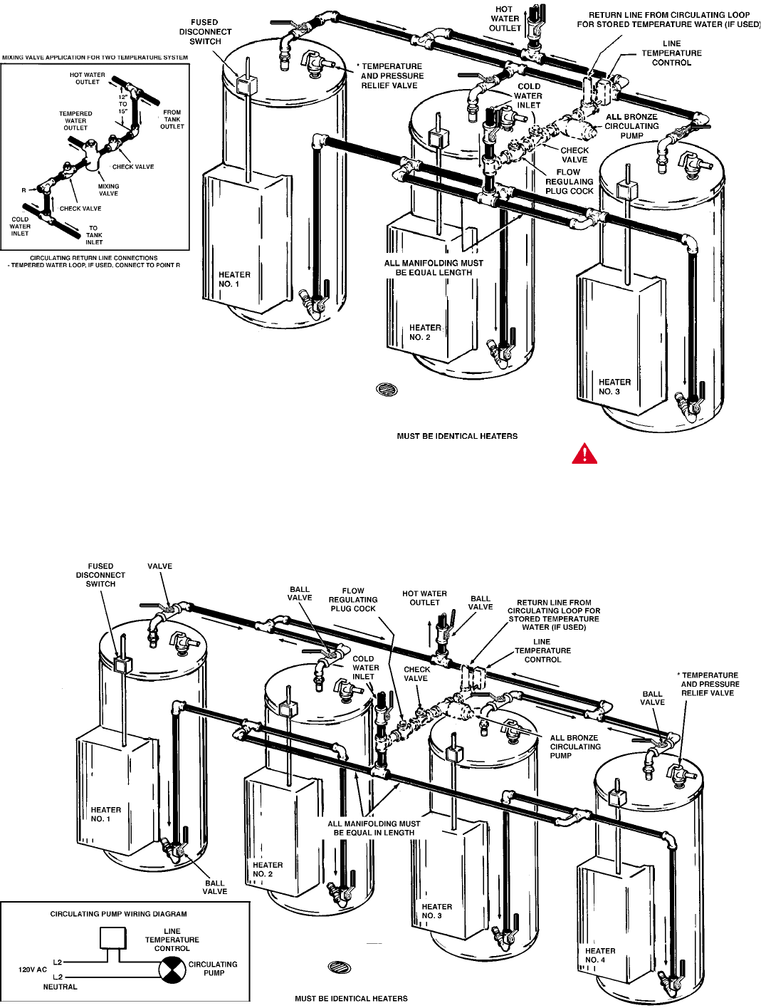
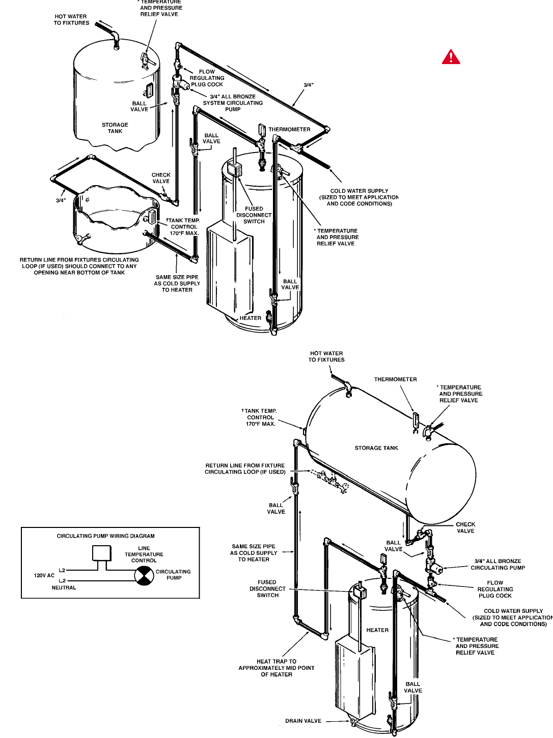
PIPING DIAGRAM
ONE OR TWO TEMPERATURE - ONE HEATER
ONE OR TWO TEMPERATURE - TWO HEATER
DANGER:
TEMPERATURE SETTING SHOULD NOT
EXCEED SAFE USE TEMPERATURE AT
FIXTURES. SEE WATER TEMPERATURE
CONTROL WARNING ON PAGES 17 & 18. IF
HIGHER PREHEAT TEMPERATURES ARE
NECESSARY TO OBTAIN ADEQUATE
BOOSTER OUTPUT, ADD AN ANTI-SCALD
VALVE FOR HOT WATER SUPPLIED TO
FIXTURES..
CAUTION: IF BUILDING COLD WATER SUPPLY HAS A
BACK-FLOW PREVENTER, CHECK VALVE OR WATER
METER WITH CHECK VALVE, PROVISIONS FOR THERMAL
EXPANSION OF WATER IN THE HOT WATER SYSTEM MUST
BE PROVIDED.
*PIPE TO OPEN DRAIN.
INSTALL IN ACCORDANCE WITH ALL LOCAL CODES.
8
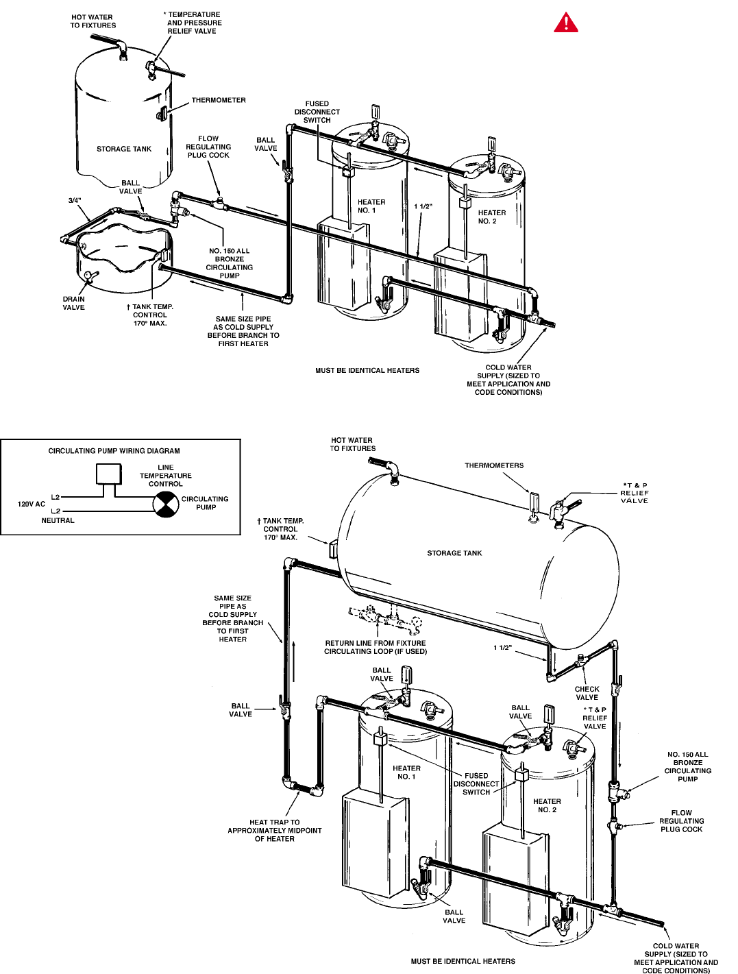
ONE OR TWO TEMPERATURE - THREE HEATERS
ONE OR TWO TEMPERATURE - FOUR HEATERS
CAUTION: IF BUILDING COLD WATER SUPPLY HAS A
BACK-FLOW PREVENTER, CHECK VALVE OR WATER
METER WITH CHECK VALVE, PROVISIONS FOR THERMAL
EXPANSION OF WATER IN THE HOT WATER SYSTEM MUST
BE PROVIDED.
*PIPE TO OPEN DRAIN.
INSTALL IN ACCORDANCE WITH ALL LOCAL CODES. DANGER:
TEMPERATURE SETTING SHOULD NOT EXCEED SAFE
USE TEMPERATURE AT FIXTURES. SEE WATER
TEMPERATURE CONTROL WARNING ON PAGES 17 &
18. IF HIGHER PREHEAT TEMPERATURES ARE
NECESSARY TO OBTAIN ADEQUATE BOOSTER OUTPUT,
ADD AN ANTI-SCALD VALVE FOR HOT WATER
SUPPLIED TO FIXTURES..
9
MEDIUM TEMPERATURE - ONE HEATER
VERTICAL STORAGE TANK
MEDIUM TEMPERATURE - ONE HEATER
HORIZONTAL STORAGE TANK
*PIPE RELIEF VALVE TO OPEN DRAIN.
†TANK TEMPERATURE CONTROL SET AT
DESIRED TEMPERATURE (MAX. 170°). HEATER
THERMOSTAT SET AT LEAST 5° HIGHER.
INSTALL IN ACCORDANCE WITH ALL LOCAL
CODES.
CAUTION: IF BUILDING COLD WATER SUPPLY
HAS A BACK-FLOW PREVENTER, CHECK
VALVE OR WATER METER WITH CHECK VALVE,
PROVISIONS FOR THERMAL EXPANSION OF
WATER IN THE HOT WATER SYSTEM MUST BE
PROVIDED.
DANGER:
TEMPERATURE SETTING SHOULD NOT
EXCEED SAFE USE TEMPERATURE AT
FIXTURES. SEE WATER TEMPERATURE
CONTROL WARNING ON PAGES 17 & 18. IF
HIGHER PREHEAT TEMPERATURES ARE
NECCESARY TO OBTAIN ADEQUATE BOOSTER
OUTPUT, ADD AN ANTI-SCALD VALVE FOR HOT
WATER SUPPLIED TO FIXTURES..
10
MEDIUM TEMPERATURE - TWO HEATERS HORIZONTAL STORAGE TANK
MEDIUM TEMPERATURE - TWO HEATERS VERTICAL STORAGE TANK
RETURN LINE FROM FIXTURE
CIRCULATING LOOP (IF USED)
SHOULD CONNECT TO ANY OPENING
NEAR BOTTOM OF TANK.
* PIPE RELIEF VALVE TO OPEN DRAIN.
† TANK TEMPERATURE CONTROL SET
AT DESIRED TEMPERATURE (MAX. 170°).
HEATER THERMOSTAT SET AT LEAST 5°
HIGHER.
INSTALL IN ACCORDANCE WITH ALL
LOCAL CODES.
CAUTION: IF BUILDING COLD WATER
SUPPLY HAS A BACK-FLOW
PREVENTER, CHECK VALVE OR WATER
METER WITH CHECK VALVE,
PROVISIONS FOR THERMAL
EXPANSION OF WATER IN THE HOT
WATER SYSTEM MUST BE PROVIDED.
NOTE:
BRANCH PIPING TO ALL HEATERS
MUST BE SAME SIZE AND LENGTH FOR
EQUAL FLOW. THESE BRANCHES MAY
BE SIZED UP TO 1 1/4” SO THAT CROSS
SECTIONAL AREAS OF ALL INLETS AND
OUTLETS AT LEAST EQUAL AREA OF
THEIR RESPECTIVE MAIN PIPING.
REVERSE RETURN PIPING SHOWN.
DANGER:
TEMPERATURE SETTING SHOULD NOT EXCEED SAFE
USE TEMPERATURE AT FIXTURES. SEE WATER
TEMPERATURE CONTROL WARNING ON PAGES 17 &
18. IF HIGHER PREHEAT TEMPERATURES ARE
NECESSARY TO OBTAIN ADEQUATE BOOSTER
OUTPUT, ADD AN ANTI-SCALD VALVE FOR HOT WATER
SUPPLIED TO FIXTURES..
11
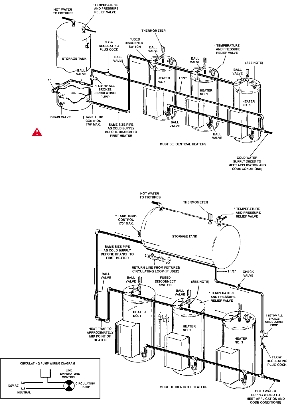
MEDIUM TEMPERATURE - THREE HEATERS HORIZONTAL STORAGE TANK
MEDIUM TEMPERATURE - THREE HEATERS VERTICAL STORAGE TANK
* PIPE RELIEF VALVE TO OPEN DRAIN
† TANK TEMPERATURE CONTROL SET
AT DESIRED TEMPERATURE (MAX. 170°).
HEATER THERMOSTAT SET AT LEAST 5°
HIGHER.
CAUTION: IF BUILDING COLD WATER
SUPPLY HAS A BACK-FLOW
PREVENTER, CHECK VALVE OR WATER
METER WITH CHECK VALVE,
PROVISIONS FOR THERMAL
EXPANSION OF WATER IN THE HOT
WATER SYSTEM MUST BE PROVIDED.
INSTALL IN ACCORDANCE WITH ALL
LOCAL CODES.
NOTE:
BRANCH PIPING TO ALL HEATERS
MUST BE SAME SIZE AND LENGTH FOR
EQUAL FLOW. THESE BRANCHES MAY
BE SIZED UP TO 1 1/4” SO THAT CROSS
SECTIONAL AREAS OF ALL INLETS AND
OUTLETS AT LEAST EQUAL AREA OF
THEIR RESPECTIVE MAIN PIPING.
REVERSE RETURN PIPING SHOWN.
DANGER:
TEMPERATURE SETTING SHOULD NOT EXCEED SAFE
USE TEMPERATURE AT FIXTURES. SEE WATER
TEMPERATURE CONTROL WARNING ON PAGES 17 &
18. IF HIGHER PREHEAT TEMPERATURES ARE
NECESSARY TO OBTAIN ADEQUATE BOOSTER
OUTPUT, ADD AN ANTI-SCALD VALVE FOR HOT WATER
SUPPLIED TO FIXTURES..
12
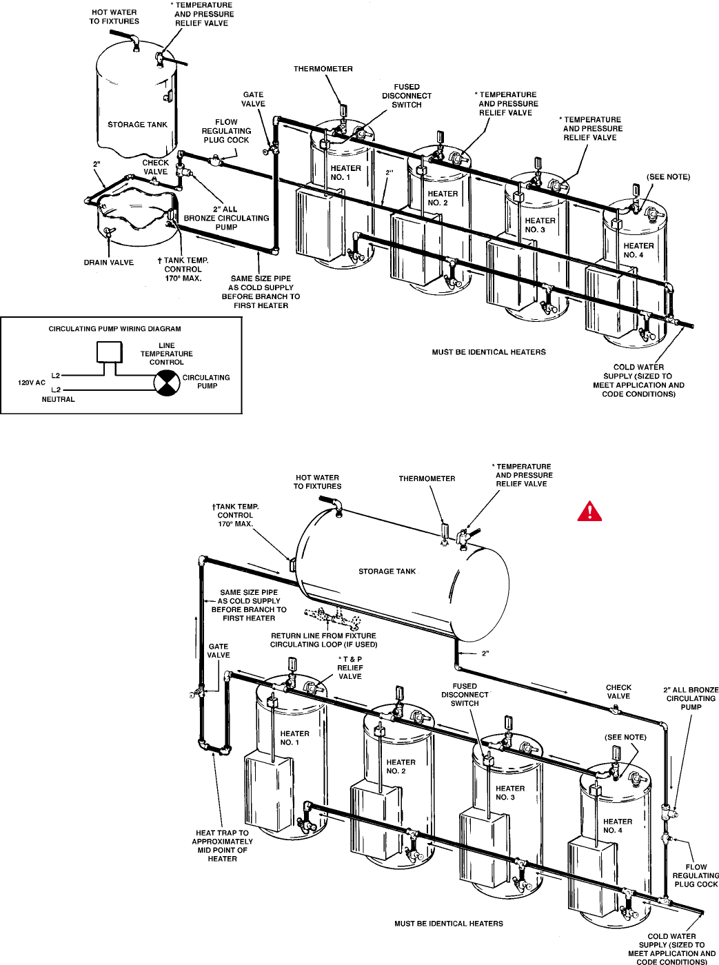
MEDIUM TEMPERATURE - FOUR HEATERS HORIZONTAL STORAGE TANK
MEDIUM TEMPERATURE - FOUR HEATERS VERTICAL STORAGE TANK
CAUTION: IF BUILDING COLD WATER
SUPPLY HAS A BACK-FLOW
PREVENTER, CHECK VALVE OR WATER
METER WITH CHECK VALVE,
PROVISIONS FOR THERMAL
EXPANSION OF WATER IN THE HOT
WATER SYSTEM MUST BE PROVIDED.
* PIPE RELIEF VALVE TO OPEN DRAIN.
† TANK TEMPERATURE CONTROL SET
AT DESIRED TEMPERATURE (MAX. 170°).
HEATER THERMOSTAT SET AT LEAST 5°
HIGHER.
INSTALL IN ACCORDANCE WITH ALL
LOCAL CODES.
NOTE:
BRANCH PIPING TO ALL HEATERS
MUST BE SAME SIZE AND LENGTH FOR
EQUAL FLOW. THESE BRANCHES MAY
BE SIZED UP TO 1 1/4” SO THAT CROSS
SECTIONAL AREAS OF ALL INLETS AND
OUTLETS AT LEAST EQUAL AREA OF
THEIR RESPECTIVE MAIN PIPING.
REVERSE RETURN PIPING SHOWN.
DANGER:
TEMPERATURE SETTING SHOULD NOT
EXCEED SAFE USE TEMPERATURE AT
FIXTURES. SEE WATER TEMPERATURE
CONTROL WARNING ON PAGES 17 & 18. IF
HIGHER PREHEAT TEMPERATURES ARE
NECESSARY TO OBTAIN ADEQUATE
BOOSTER OUTPUT, ADD AN ANTI-SCALD
VALVE FOR HOT WATER SUPPLIED TO
FIXTURES..
13
ELECTRICAL
GENERAL
The installation must conform to these instructions, the local
code authority having jurisdiction, and the requirements of the
power company. In the absence of code requirements follow
the latest version of NFPA-70, The National Electrical Code
which may be ordered from: American National Standards
Institute, 1430 Broadway, New York, NY 10018.
WARNING
AN ELECTRICAL GROUND IS REQUIRED TO REDUCE RISK
OF ELECTRIC SHOCK OR POSSIBLE ELECTROCUTION. The
water heater should be connected to a separate, grounded,
branch circuit with overcurrent protection and disconnect switch.
The water heater should be grounded in accordance with
national and local codes.
Check the heater model and rating plate information against
the characteristics of the branch circuit electrical supply. DO NOT
CONNECT THE HEATER TO AN IMPROPER SOURCE OF
ELECTRICITY.
Voltage applied to the heater should not vary more than +5% to
-10% of the model and rating plate marking for satisfactory
operation.
DO NOT ENERGIZE THE BRANCH CIRCUIT FOR ANY REASON
BEFORE THE HEATER TANK IS FILLED WITH WATER. DOING
SO WILL CAUSE THE HEATING ELEMENT TO BURN OUT.
The branch circuit is connected to the heater wiring through an
opening provided on the heater.
BRANCH CIRCUIT
The branch circuit wire and fuse size should be established
through reference to the latest version of the National Electrical
Code or other locally approved source in conjunction with the
heater amperage rating. Branch circuit wires should be 75°C
temperature rated. For convenience, portions of the wire size
tables from the Code are reproduced here. It is suggested the
electrician size the branch circuit at 125 percent of the heater
ampere rating and further increase wire size as necessary to
compensate for voltage drop in long runs. Branch circuit voltage
drop should not exceed 3% at the heater.
TABLE 310-16. Allowable Ampacities of Insulated Conductors
Not More Than Three Conductors in Raceway or Cable or Earth
(Directly Buried), Based on Ambient Temperature of 30°C (86°F)
Size Temperature Rating of Conductor, See table 310-13 Size
60°C 75°C 85°C 90°C 60°C 75°C 85°C 90°C
(140°F) (167°F) (185°F) (194°F) (140°F) (167°F) (185°F) (194°F)
TYPES TYPES TYPES TYPES TYPES TYPES TYPES TYPES
RUW, T FEPW V, MI TA, TBS RUW, T RH, RHW V, MI TA, TBS,
AWG TW, UF RH,RHW SA, AVB TW, UF RUH SA, AVB
RUH, SIS, =FEP, THW, SIS, AWG
THW, =FEPB, THWN =RHH,
MCM THWN, =RHH, XHHW, =THHN, MCM
XHHW =THHN, USE =XHHW*
USE, ZW =XHHW*
COPPER ALUMINUM OR COPPER-CLAD ALUMINUM
18 …… …… …… 21 …… …… …… …… ……
16 …… …… 22 22 …… …… …… …… ……
14 15 15 25 25 …… …… …… …… ……
12 20 20 30 30 15 15 25 25 12
10 30 30 40 40 25 25 30 30 10
840 4550 50 304040 408
655 6570 70 405055 556
470 8590 90 556570 704
3 80 100 105 105 65 75 80 80 3
2 115 120 120 75 90 95 95 2
1 130 140 140 100 110 110 1
0 150 155 155 120 125 125 0
00 175 185 185 135 145 145 00
000 200 210 210 155 165 165 000
0000 230 235 235 180 185 185 0000
250 255 270 270 205 215 215 250
300 285 300 300 230 240 240 300
350 310 325 325 250 260 260 350
400 335 360 360 270 290 290 400
500 380 405 405 310 330 330 500
CORRECTION FACTORS
Ambient For ambient temperatures over 30°C, multiply the amacities shown by the appropriate Ambient
Temp.°C correction factor to determine the maximum allowable load current. Temp.°F
31-40 .82 .88 .90 .91 .82 .88 .90 .91 86-104
41-50 .58 .75 .80 .82 .58 .75 .80 .82 105-122
51-60 …… .58 .67 .71 …… .58 .67 .71 123-141
61-70 …… .35 .52 .58 …… .35 .52 .58 142-158
71-80 …… …… .30 .41 …… …… .30 .41 159-176
= The load current rating and the overcurrent protection for these conductors shall not exceed 15 amperes for 14 AWG,
20 amperes for 12 AWG, and 30 amperes for 10 AWG copper; or 15 amperes for 12 AWG and 25 amperes for 10 AWG
aluminum and copper-clad aluminum.
* For dry locations only. See 75°C column for wet locations.
14
AMPERAGE TABLE/OVERCURRENT
PROTECTION
This table provides the total connected heating element load in
amperes for branch circuit conductor and over current protection
sizing. Single-phase heaters are two wire circuits. Three-phase
heaters are three wire circuits. In addition to the foregoing a
ground conductor may be required.
The rating of the overcurrent protection should be computed on
the basis of 125 percent of the total connected load amperage.
Where the standard ratings and settings do not correspond with
this computation, the next higher standard rating or setting
should be selected.
HEATER CIRCUITS
The water heater’s electrical components are pictured and
identified in Figure 1.
The following describes the heater circuits and includes wiring
diagrams. All heater circuits are designed for 60 hertz alternating
current.
CONTROL CIRCUIT
The heater is equipped with 120 volt control circuit where all of
the heating elements are switched on and off together. This is
the standard circuit and may be used with up to five elements.
The control circuit wiring is 14 AWG rated 600 volts, 105°C.
A low water cutoff switch is available as an optional safety device
to protect the elements from damage due to lack of water in the
heater.
POWER CIRCUIT
Power circuit wiring is rated 600 volts, 75°C.
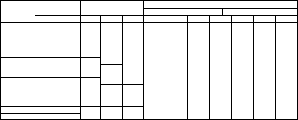
WIRING DIAGRAMS
The following wiring diagrams are included in this manual to
show typical arrangement of electrical components in the control
and power circuits by voltage and phase characteristics. They
are to be used as a reference by the installer or servicer in
performing their work. An actual diagram of the water heater
wiring is furnished with the heater.
STANDARD KW INPUTS
Standard Immersion Number of Full Load Current In Amperes
KW Heaters*** 50A Contractors Single Phase Three Phase
Ratings No. Of Wattage 208V 240V 480V 208V 240V 277V 480V 208V 240V 480V
3 1 3,000 14.4 12.5 10.8 6.3 8.3 7.2 3.6
6 1 6,000 1 28.8 25.0 21.2 12.5 16.7 14.4 7.2
9 1 9,000 1 43.3 37.5 32.5 18.8 25.0 21.7 10.8
12 1 12,000 1 57.7 50.0 43.3 25.0 33.3 28.9 14.4
15 1 15,000 72.1 62.5 54.2 31.3 41.6 36.1 18.0
18* 1 18,000 86.5 75.0 65.0 37.5 50.0 43.3 21.7
24 2 12,000 2 115.4 100.0 86.6 50.0 66.6 57.7 28.9
30 2 15,000 2 144.2 125.0 108.3 62.5 83.3 72.2 36.1
36* 2 18,000 173.1 150.0 130.0 75.0 99.9 86.6 43.3
45 3 15,000 3 3 216.3 187.5 162.5 93.8 124.9 108.3 54.1
54 3 18,000 2 N/A 225.0 194.9 112.5 149.9 129.9 65.0
60** 4 15,000 4 4 N/A 250.0 216.6 125 166.7 145 72
75** 5 18,000 5 5 3 N/A 312.5 270.8 156 208.4 181 90
90** 5 18,000 N/A 375.0 324.9 188 250 217 108
* 208V models use one additional immersion heater.
** Available on 50 gallon models or larger.
***Each immersion heater contains three electric elements.
15
SMALL COMMERCIAL WIRE DIAGRAM
208-240V / 3PH
SMALL COMMERCIAL WIRE DIAGRAM
208-240V / 3-1PH

16
3-1 PHASE CONVERSIONS
In the case where the unit is phase convertible and it has only one contactor, jumper wires (provided) must be added according to
the phase of the supply voltage. See the diagram below. For single-phase connection, jumpers A-C and B-D must be added. For
three-phase connection, jumper B-C must be added.
3-1 PHASE CONTACTOR JUMPER CONFIGURATION
FIGURE 1
1 PHASE CONNECTION FIGURE 2
3 PHASE CONNECTION
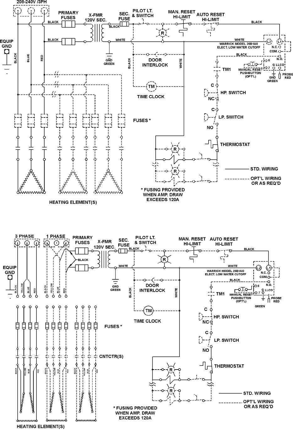
SMALL COMMERCIAL WIRE DIAGRAM
300-600V / 3PH
17
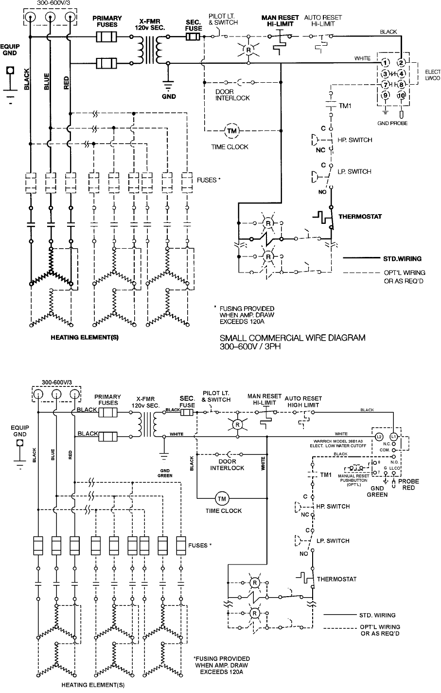
SMALL COMMERCIAL WIRE DIAGRAM
SINGLE PHASE
SMALL COMMERCIAL WIRE DIAGRAM
300-600V / 3PH
18
OPERATION
GENERAL
Never operate the heating elements without being certain the
water heater is filled with water, and a temperature and pressure
relief valve is installed in the relief valve opening.
FILLING
1. Turn off the electrical disconnect switch.
2. Close the water heater drain valve by turning knob
to right (clockwise).
3. Open a nearby hot water faucet to permit the air in the
system to escape.
4. Fully open the cold water inlet valve allowing the heater
and piping to be filled.
5. Close the hot water faucet as water starts to flow. The
heater is now ready for START UP and TEMPERATURE
REGULATION.
START UP
The following checks should be made by the installer when the
heater is placed into operation for the first time.
1. Open the hinged access door, check all water and electrical
connections for tightness. Also check connections on top
and side of heater.
• Repair water leaks and tighten electrical connections
as necessary.
2. Depress red button on manual reset high limit switch.
3. Turn on the electrical disconnect switch.
4. Observe the operation of the electrical components during
the first heating cycle. Use care as the electrical circuits
are energized.
• Thermostat and contactor operation should be
checkedby (a) manually operating thermostat and
(b) allowing the heater to come up to temperature
and shutoff automatically.
• The thermostat operates all contactor coils
simultaneously.
5. Close the access door.
TEMPERATURE REGULATION
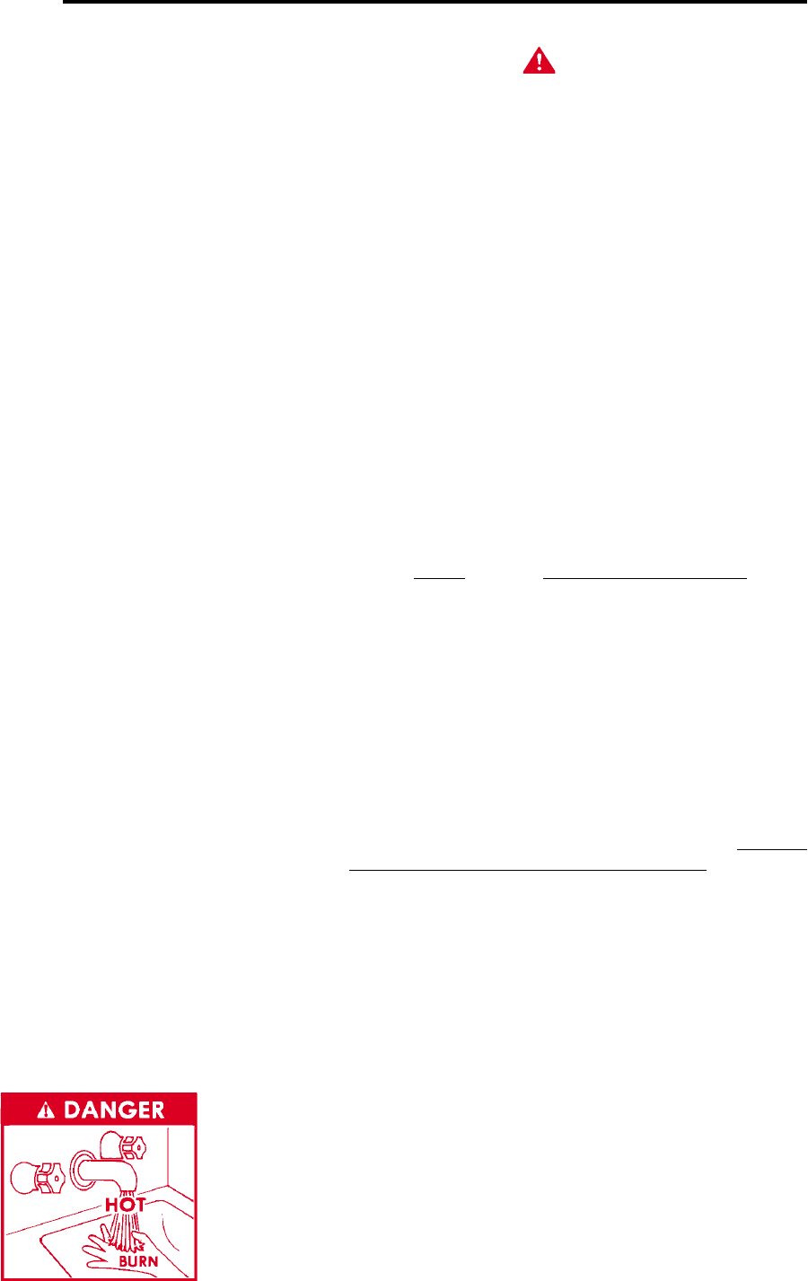
DANGER
THIS WATER HEATER IS EQUIPPED WITH AN ADJUSTABLE
THERMOSTAT TO CONTROL WATER TEMPERATURE. HOT
WATER TEMPERATURES REQUIRED FOR AUTOMATIC
DISHWASHER AND LAUNDRY USE CAN CAUSE SCALD
BURNS RESULTING IN SERIOUS PERSONAL INJURY AND/
OR DEATH. THE TEMPERATURE AT WHICH INJURY OCCURS
VARIES WITH THE PERSON’S AGE AND TIME OF EXPOSURE.
THE SLOWER RESPONSE TIME OF DISABLED PERSONS
INCREASES THE HAZARDS TO THEM. NEVER ALLOW SMALL
CHILDREN TO A HOT WATER TAP, OR TO DRAW THEIR OWN
BATH WATER. NEVER LEAVE A CHILD DISABLED PERSON
UNATTENDED IN A BATHTUB OR SHOWER.
THE WATER HEATER SHOULD BE LOCATED IN AN AREA
WHERE THE GENERAL PUBLIC DOES NOT HAVE ACCESS TO
SET TEMPERATURES.
SETTING THE WATER HEATER TEMPERATURE AT 120°F WILL
REDUCE THE RISK OF SCALDS. Some states require settings
at specific lower temperatures.
Figure 1 shows the approximate time-to-burn relationship for
normal adult skin.
Temperature Time to Produce 2nd & 3rd
Setting Degree Burns on Adult Skin
180°F (82°C) Nearly instantaneous
170°F (77°C) Nearly instantaneous
160°F (71°C) About 1/2 second
150°F (65°C) About 1-1/2 seconds
140°F (60°C) Less than 5 seconds
130°F (54°C) About 30 seconds
120°F (49°C) More than 5 minutes
FIGURE 1
Valves for reducing point-of-use temperature by mixing cold and
hot water are available. Also available are inexpensive devices
that attach to faucets to limit hot water temperatures Contact a
licensed plumber or the local plumbing authority.
The thermostat factory setting is 130°F. The dial is adjustable
through a range of 95° to 194°.
The thermostat is behind the front access door. TURN OFF THE
ELECTRICAL DISCONNECT SWITCH BEFORE OPENING
DOOR.
• It is suggested the thermostat be turned to the lowest
setting which satisfies the hot water requirements
of the system. This helps minimize water scale
formations on the heating elements.
• The thermostat contacts close on about 6°F (not
adjustable) drop in water temperature.
• Where multiple thermostats are used, they may be
all set at the same temperature or 2° to 4°F apart to
achieve “step control”. The bottom thermostat is
set the hottest and top thermostat the coolest.
19
MAINTENANCE
Always close the front access door after making a temperature
adjustment. Turn on electricity.
DRAINING
The water heater must be drained if it is to be shut down and
exposed to freezing temperatures. Maintenance and service
procedures may also require draining the heater.
1. Turn off the electrical disconnect switch.
2. Close the supply water inlet valve to heater.
GENERAL
Periodically the drain valve should be opened and the water
allowed to run until it flows clean. This will help to prevent
sediment build-up in the tank bottom.
Periodically check the temperature and pressure relief valve to
ensure that it is in operating condition. Lift the lever at the top of
the valve several times until the valve seats properly and operates
freely.
CAUTION
THE WATER PASSING OUT OF THE VALVE DURING THIS
CHECKING OPERATION MAY BE EXTREMELY HOT.
Water heater maintenance includes periodic tank flushing and
cleaning, and removal of lime scale from the heating elements.
Component Operation Interval Required
Flushing Monthly -------------
Tank Sediment
Removal As needed -------------
Elements Lime Scale As needed UN•Lime® delimer
Removal and element gaskets,
Part No.5109.
Tank flushing should be performed in accordance with the above
schedule. Tank sediment removal and element lime scale
removal must be performed when needed as determined by
periodic inspections. Following are the instructions for
performing recommended maintenance.
FLUSHING
The water heater drain valve should be opened once a month to
help prevent sediment buildup on the tank bottom.
1. Turn off the electrical disconnect switch.
2. Attach hose to outlet opening of drain valve and direct
end to drain.
• Open the drain valve by turning the knob to the
left (counterclockwise). Allow water to flow until it runs
clean.
• If water does not flow from opened drain valve,
follow instructions for sediment removal.
3. When finished flushing:
• Close heater drain valve and remove hose.
• Turn on electricity.
SEDIMENT REMOVAL
Water borne impurities consist of fine particles of soil and sand
which settle out and form a layer of sediment on the bottom of
the tank. In time, if not removed, the level of sediment might
reach the heating elements and cause their failure.
For convenience, sediment removal and element lime scale
removal should be performed at the same time as follows.
LIME SCALE REMOVAL
Lime scale accumulations on the heating elements is a normal
condition, common to all immersion type elements. Factors
which affect the amount of this formation are:
1. Amount of hot water used. As the volume of water heated
increases, more scale results.
2. Water temperature. As the temperature of water is in-
creased, more scale is deposited on the elements.
3. Characteristics of water supply. Regardless of water
treatment, the elements should be examined regularly.
Lime scale accumulations may cause noises to occur during
operation.
It is recommended that a heating element be removed
periodically for examination. If it is scaled, all of the elements
should be removed and cleaned. If the tank bottom has an
accumulation of sediment it should be cleaned.
Lime scale should be removed by dissolving the accumulation
in UN•LIME® delimer. UN•LIME is a non-muriatic delimer,
available from A.O. Smith Water Products Company, Product
Service Division, 5621 W. 115th ST., Alsip, IL. 60803. Do not
use muriatic or hydrochloric acid base deliming solutions to
remove lime scale from the elements.
1. Turn off electrical disconnect switch.
2. Drain the heater following DRAINING instructions.
3. Open front access door.
4. Disconnect the element wiring. Try not to disturb the
wiring unnecessarily and reconnection will be easier.
3. Attach hose to outlet opening of drain valve and direct
end to drain.
4. Open a nearby hot water faucet and the heater drain
valve.
5. If the heater is being drained for extended shutdown, it is
suggested the drain valve be left open during this period.
The hose may be removed.
• Follow FILLING instructions when restoring hot
water service.
20
5. Remove the bolts from each element.
6. Remove the elements from the openings.
• Use a twisting, pulling action to remove elements
scaled beyond size of the tank openings.
• Brush loose scale from elements.
7. Lime scale removal.
• Place limed ends of heating elements into UN•LIME
delimer and allow scale to dissolve. Do not permit
delimer or water to contact heating element electrical
terminals.
Other scale removal:
• Silicates, sulfates and aluminates must be removed
by scraping or other mechanical means. Lime scale
solvents will not remove these types of scale
which are occasionally encountered.
8. Flush cleaned ends of elements with water when deliming
or cleaning is completed.
9. Remove sediment and scale from the tank bottom through
the access provided by the element opening(s).
• The cold water inlet valve and drain valve may be
opened to aid the cleanout process.
10. Clean remaining gasket material from tank and element
flanges. DO not reuse original element gaskets.
• The element gaskets should be replaced whenever an
element is removed.
11. Put new gaskets on each element and install into tank
openings.
• Uniformly tighten element bolts.
12. Attach element wires to connection points from which
they were removed.
13. Follow FILLING instruction to restore hot water service.
• Check for water leaks around elements and proper
operation when heater is filled.
• Close front access door.
CHECKLIST
Before calling for service, check the following points to see if
the cause of trouble can be identified and corrected. Reviewing
this checklist may eliminate the need of a service call and quickly
restore hot water service. Figure 1 identifies the location of all
of the heater components.
BE SURE TO TURN OFF THE ELECTRICITY WHEN CHECKING
EQUIPMENT.
Not enough or no hot water.
1. Be certain the electrical disconnect switch serving the
water heater is in the ON position.
2. Check the fuses.
• The electrical disconnect switch usually contains
fuses.
3. If the water was excessively hot, and is now cold, the
high limit switch may have operated.
• To reset, remove the plug from the top cover of the
heater and push the reset button.
• Repeated operation of the high temperature cutoff
should be investigated by your dealer.
4. The capacity of the heater may have been exceeded
by a large demand for hot water.
• Large demands require a recovery period to restore
water temperature.
5. Cooler incoming water temperature will lengthen the
time required to heat water to the desired temperature.
6. Look for hot water wastage and leakage.
7. Sediment or lime scale may be affecting water heater
operation. Refer to page 18 for details.
Water is too hot
1. Refer to TEMPERATURE REGULATION.
Water heater makes sounds
1. Sediment or lime scale accumulations on the elements
causes sizzling and hissing noises when the heater is
operating.
• The sounds are normal. However, the tank bottom `
and elements should be cleaned. Refer to page 18
for details.
2. Some of the electrical components of the water heater
make sounds which are normal.
• Contactors will “click” or snap as the heater starts
and stops.
• Contactors often hum.
Water leakage is suspected.
1. Check to see if the heater drain valve is tightly closed
2. If the outlet of the relief valve is leaking it may represent:
• Excessive water temperature.
• Faulty relief valve.
• Excessive water pressure.
• Excessive water pressure is the most common cause
of relief valve leakage. It is often caused by a “closed
system”. A check valve in the inlet system will not permit
the expanded hot water volume to equalize pressure
with the main. A relief valve must release this water or
the water heater or plumbing system will be damaged.

21
When such a condition is encountered, local codes or
inspection agency should be consulted to determine which
system is acceptable in your area. These may consist of:
• Installation of a second relief valve set to lower
than the primary safety relief valve.
• An expansion tank of suitable pressure and provision
to avoid water logging.
• Removal of the check valve.
4. Examine the flange area of the elements for gasket
leakage.
• Tighten the bolts or, if necessary, follow the WATER
AND LIME SCALE REMOVAL procedure to replace
the gaskets.
• Refer to “LEAKAGE CHECKPOINTS” on page 22.
IF YOU CANNOT IDENTIFY OR CORRECT THE SOURCE OF
MALFUNCTION
1. Place the water heater electrical switch in the OFF
position
2. Close the supply water inlet valve to the heater.
3. Contact your dealer.
REPLACEMENT PARTS
Replacement parts may be ordered through dealers, authorized
servicers or distributors. Refer to Yellow Pages for where to call
or contact the A.O. Smith Water Products Company, Product
Service Division, 5621 W. 115th Street, Alsip, IL 60803, 1-800-
433-2545 When ordering parts, specify complete model no.,
serial no., (see rating plate), quantity and name of part desired.
Standard hardware items should be purchased locally.
REPLACEMENT PARTS
22
LEAKAGE CHECKPOINTS
INSTRUCTIONS: USE THIS ILLUSTRATION AS A GUIDE WHEN CHECKING FOR SOURCES OF WATER LEAKAGE.
YOU OR YOUR DEALER MAY BE ABLE TO CORRECT WHAT APPEARS TO BE A PROBLEM.
Water on side of the tank may be condensation due
to the panel or insulation not being in place.
Relief valve operation and leakage may be due to
water expansion during heating cycle or foreign
material on seat of valve. If the valve is not piped to
an open drain the released water could be mistaken
for a leaking heater. To check where threaded
portion enters tank, insert Q-tip or similar absorbent
material between jacket opening and valve to swab
spud area. Remove valve* if leak is indicated and
repair with pipe joint compound.
Water leaks at the elements may be due to:
1. Defective element which leaks at terminals or
through flange. Replace element*.
2. Loose element/gasket leak:
Flange type: Tighten screws with wrench. If leak
continues remove element* and discard gasket.
Clean gasket seating areas and reinstall element
with new gasket.
NOTE: Part No. 5288 scale cleaning replacement
screws available where threads have become
rusted or damaged, preventing tightening.
Condensation and dripping may appear on pipes
when cold water temperature is low. Pipe fitting may
be leaking.
All water which appears at the heater bottom or on the surrounding
floor may be caused by condensation, loose connections or relief
valve operation and leakage. Do not replace the heater until a full
inspection of all potential leak points is made and corrective steps
taken to stop the leak. Leakage from other appliances, water
lines or ground seepage should also be suspected until proven
otherwise.
Where possible, remove or lift top cover to examine
threads of fittings installed into tank for evidence of
leakage. Correct fitting leaks as necessary.
Drain valve leakage could be from the valve
itself. Either correct the problem or replace the
valve.* To check for leakage where threaded
portion enters tank, insert Q-tip or similar
absorbent material between jacket opening
and valve to swab spud area. Remove valve*
if leak is indicated and repair with pipe joint
compound.
*Contact your dealer as it is necessary to shut
off electricity and drain tank to perform
procedure.
ANODE

23
MODEL DSE LIMITED WARRANTY
A.O. Smith Corporation, the warrantor, extends the following LIMITED WARRANTY to the owner of this water heater:
1. THE TANK
If the glass-lined tank in this water heater shall prove upon examination by the warrantor to have leaked due to natural corrosion from potable
water therein, during the first THREE years after initial installation, the warrantor will supply a complete new A.O. Smith water heater of
equivalent size and current model. Some government agencies are requiring energy efficient standards for water heaters. In the event
regulations prohibit sale of a model of equivalent size and construction, A.O. Smith will provide a model which complies with the regulations of
your area, in which case the consumer will be charged the difference in price between the like replacement and the energy efficient model
required. The warranty on the replacement water heater will be limited to the unexpired term of the original warranty.
2. ALL OTHER PARTS
If within ONE year after initial installation of this water heater, any part or portion shall prove upon examination by the warrantor to be defective
in material or workmanship, the warrantor will repair or replace such part or portion at its option.
3. CONDITIONS AND EXCEPTIONS
This warranty shall apply only when the water heater is installed in accordance with local plumbing and building codes, ordinances and regulations,
the printed instructions provided with it and good industry practices. In addition, a temperature and pressure relief valve, certified by A.G.A. and
approved by the American Society of Mechanical Engineers, must have been installed.
a. This warranty shall apply only when the heater is used:
(1) at temperatures not exceeding the maximum setting of its thermostat;
(2) at water pressure not exceeding the working pressure shown on the water heater;
(3) when operated free from the damaging effects of uncontrolled water hammer;
(4) when filled with potable water, free to circulate at all times;
(5) in a non-corrosive and non-contaminated atmosphere;
(6) with factory approved anode(s) installed;
(7) in the United States, its territories or possessions, and Canada.
b. Any accident to the water heater, any misuse, abuse (including freezing) or alteration of it, any operation of it in a modified
form, any use of insulation blankets, or any attempt to repair tank leaks will void this warranty.
c. This warranty is void if a device acting as a backflow prevention device (check valves etc) is installed in the cold water supply the heater
is connected to, unless an effective method of controlling thermal expansion is also installed at the heater(s) and operational at all times.
The relief valve installed on the heater is not an acceptable method.
4. SERVICE AND REPAIR EXPENSES
Under the limited warranty the warrantor will provide only a replacement water heater or part thereof. The owner is responsible for all other
costs. Such costs may include but are not limited to:
a. Labor charges for service removal, repair or reinstallation of the water heater or any component part;
b. Shipping, delivery, handling, and administrative charges for forwarding the new heater or replacement part from the nearest
distributor and returning the claimed defective heater or part to such distributor.
c. All cost necessary or incidental for any material and/or permits required for installation of the replacement heater or part.
5. LIMITATIONS ON IMPLIED WARRANTIES
Implied warranties, including the warranty of merchantability imposed on the sale of this heater under state law are limited to (1) year duration for
the heater or any of its parts. Some states do not allow limitation on how long an implied warranty lasts, so the above limitation may not apply to
you.
6. CLAIM PROCEDURE
Any claim under the warranty should be initiated with the dealer who sold the heater, or with any other dealer handling the warrantor’s products.
If this is not practicable, the owner should contact:
U.S. Customers Canadian Customers
A.O. Smith Water Products Company A.O.Smith Enterprises Ltd.
5621 W. 115th Street P.O.Box 310 - 768 Erie Street
Alsip, IL 60803 Stratford, Ontario N5A 6T3
Telephone: 800-323-2636 Telephone: (519) 271-5800
a. The warrantor will only honor replacement with identical or similar water heater or parts thereof which are manufactured or distributed by the
warrantor.
b. Dealer replacements are made subject to in-warranty validation by warrantor.
7. DISCLAIMERS
NO OTHER EXPRESS WARRANTY HAS BEEN OR WILL BE MADE IN BEHALF OF THE WARRANTOR WITH RESPECT TO THE HEATER OR
THE INSTALLATION OPERATION REPAIR OR REPLACEMENT OF THE HEATER. THE WARRANTOR SHALL NOT BE RESPONSIBLE FOR
WATER DAMAGE, LOSS OF USE OF THE UNIT, INCONVENIENCE, LOSS OF DAMAGE TO PERSONAL PROPERTY OR OTHER
CONSEQUENTIAL DAMAGE. THE WARRANTOR SHALL NOT BE LIABLE BY VIRTUE OF THIS WARRANTY OR OTHERWISE FOR DAMAGE
TO ANY PERSONS OR PROPERTY, WHETHER DIRECT OR INDIRECT, AND WHETHER ARISING IN CONTRACT OR IN TORT.
a. Some states do not allow the exclusion or limitation of incidental or consequential damage, so the above limitations or exclusions may not apply
to you.
b. This warranty gives you specific legal rights, and you may also have other rights which vary from state to state.
Fill in the following for your own reference. Keep it. Registration is not a condition of warranty. The model and serial number are found on the
heater’s rating plate.
Model No. ____________________________________ Serial No. _____________________________________ Date Installed _______________
Dealer’s Name __________________________________________________________________________________________________________
Dealer’s Address _____________________________________________________________________________ Phone No. __________________
City and State _______________________________________________________________________________ Zip Code __________________
KEEP THIS WARRANTY AND MANUAL POSTED ADJACENT TO THE HEATER FOR FUTURE
REFERENCE WHENEVER MAINTENANCE, ADJUSTMENT OR SERVICE IS REQUIRED.

24
5621 W. 115TH STREET, ALSIP, IL 60803
Phone: 800-433-2545 Fax: 800-433-2515
www.hotwater.com E-Mail: parts@hotwater.com
REPLACEMENT PARTS
