ABB Drives APWSERIES Assistant Control Panel with Bluetooth interface User Manual APWSERIES UserMan
ABB Oy, Drives Assistant Control Panel with Bluetooth interface APWSERIES UserMan
UserManual.wiki
>
ABB Drives
>
APWSERIES User Manual
APWSERIES_UserMan
Navigation menu
Upload a User Manual
Namespaces
Wiki Guide
HTML
PDF
Info
Views
User Manual
Discussion / Help
Navigation
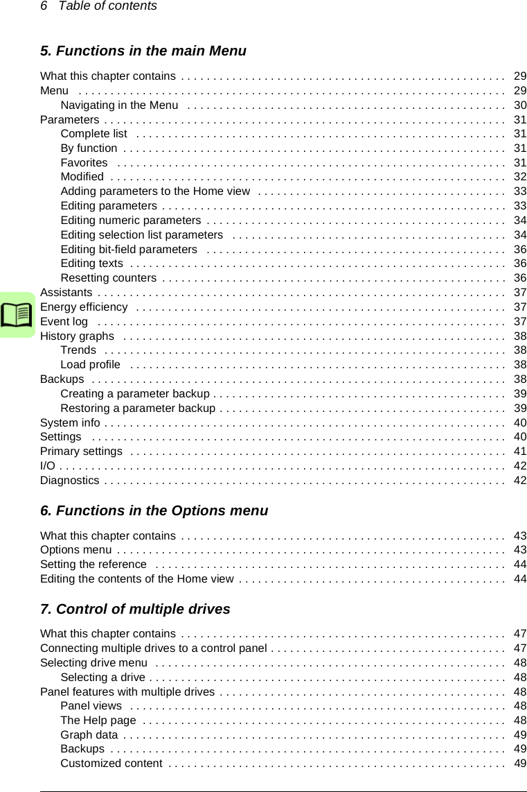
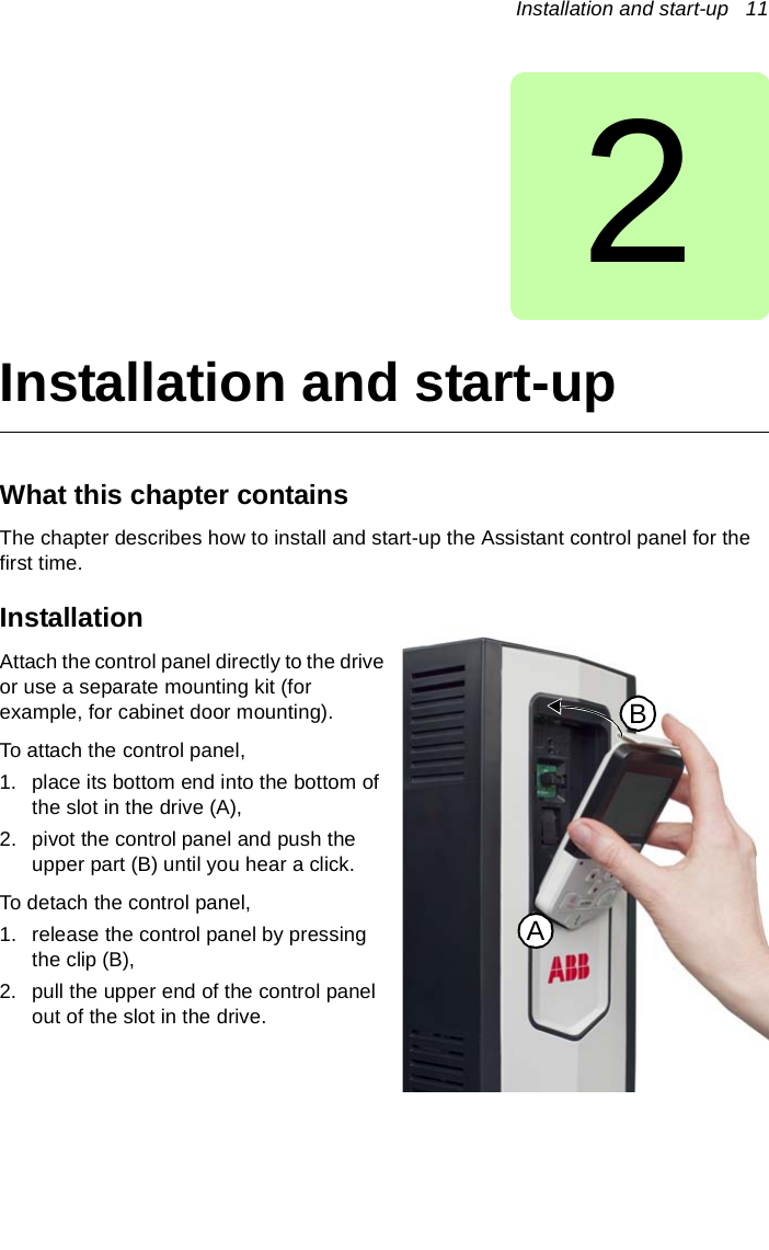

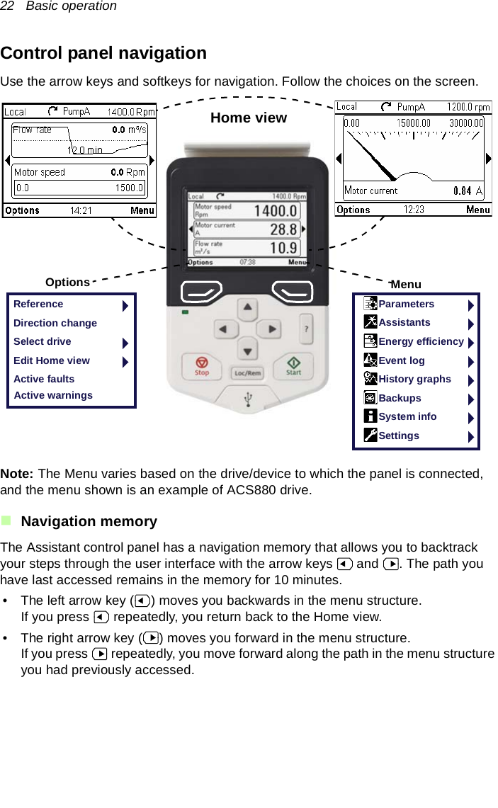


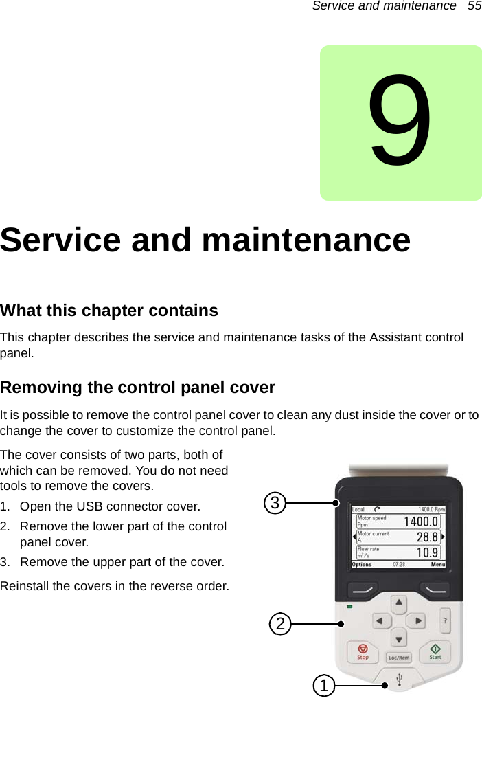
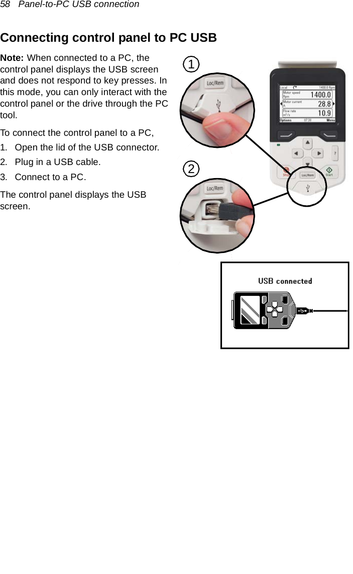
![Panel-to-PC USB connection 59Connecting a PC tool to a drive through the control panelYou can use the control panel to connect an ABB PC tool to the drive. When using the control panel, you can only access the drive from the PC tool.1. Install an ABB PC tool to the PC. 2. Connect the control panel to the drive. 3. Connect the control panel to the PC with a USB cable as instructed in Connecting control panel to PC USB (page 58).4. If Windows prompts you to install USB drivers, install them as instructed in Drive composer user’s manual (3AUA0000094606 [English]).The behavior depends on the current control location of the drive. See Connecting in local control mode (page 59) and Connecting in remote control mode (page 59).Connecting in local control modeWhen you connect the control panel in local control mode to a PC, local control is transferred to the PC tool and the control panel displays the USB screen. The drive retains its present reference and direction.When you have finished using the PC tool, close the connection through the PC tool first and then disconnect the USB cable. Local control is transferred back to the control panel and the drive retains its present reference and direction.Note: If you disconnect the USB cable before closing the connection, a Local loss fault is triggered.Connecting in remote control modeWhen you connect the control panel in remote control mode to a PC, the control panel displays the USB screen and you can only interact with the control panel through the PC tool. The drive remains in remote control, but you can switch over to local control using the PC tool.When you disconnect the PC tool, the control panel exits the USB screen and the drive resumes its normal operation.](https://usermanual.wiki/ABB-Drives/APWSERIES/User-Guide-2796476-Page-59.png)
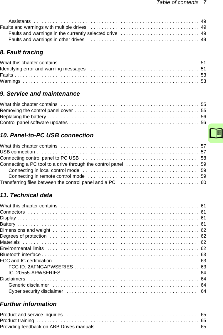
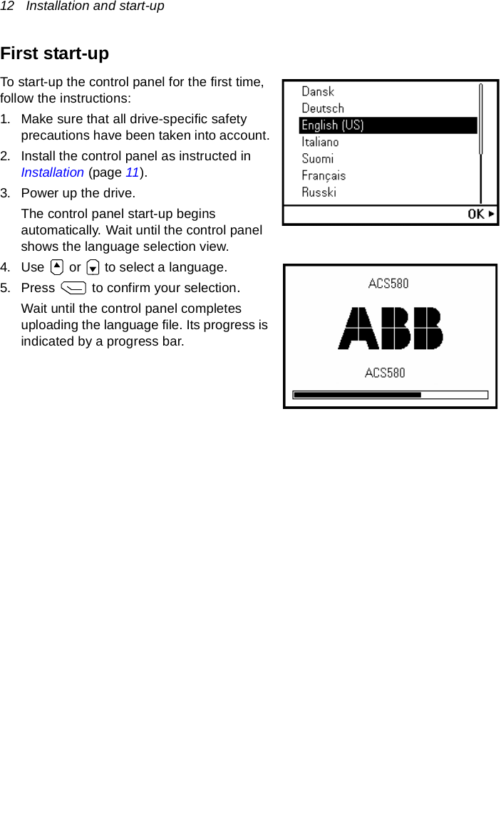
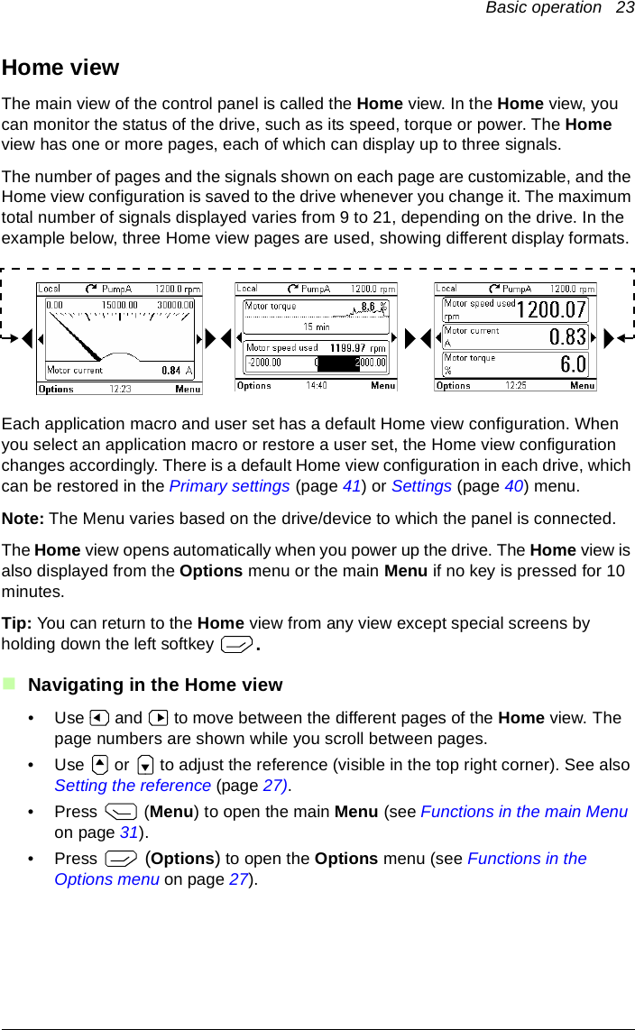
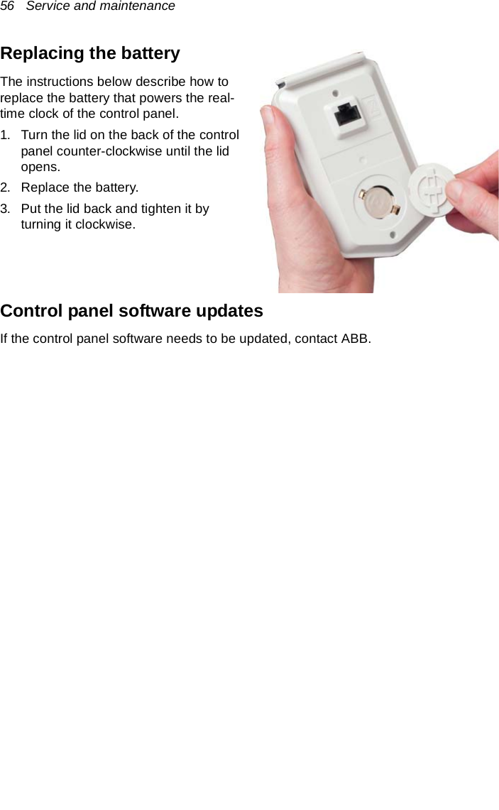
![60 Panel-to-PC USB connectionTransferring files between the control panel and a PC1. Connect the control panel to a PC with a USB cable as instructed in Connecting control panel to PC USB (page 58).2. If Windows prompts you to install USB drivers, install them as instructed in Drive composer user’s manual (3AUA0000094606 [English]).The control panel appears as an MTP device in Windows Explorer.3. Open ABB Drives Assistant control panel with Windows Explorer, and go to the directory where the files are stored.• Screenshots are stored in: ABB Drives Assistant control panel\ABB Drives Assistant control panel_a\screen• Backup files are stored in: ABB Drives Assistant control panel\ABB Drives Assistant control panel_a\backupYou can copy files to and from the folders just like any other files with Windows Explorer.](https://usermanual.wiki/ABB-Drives/APWSERIES/User-Guide-2796476-Page-60.png)
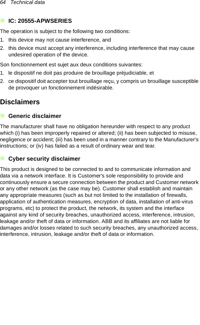
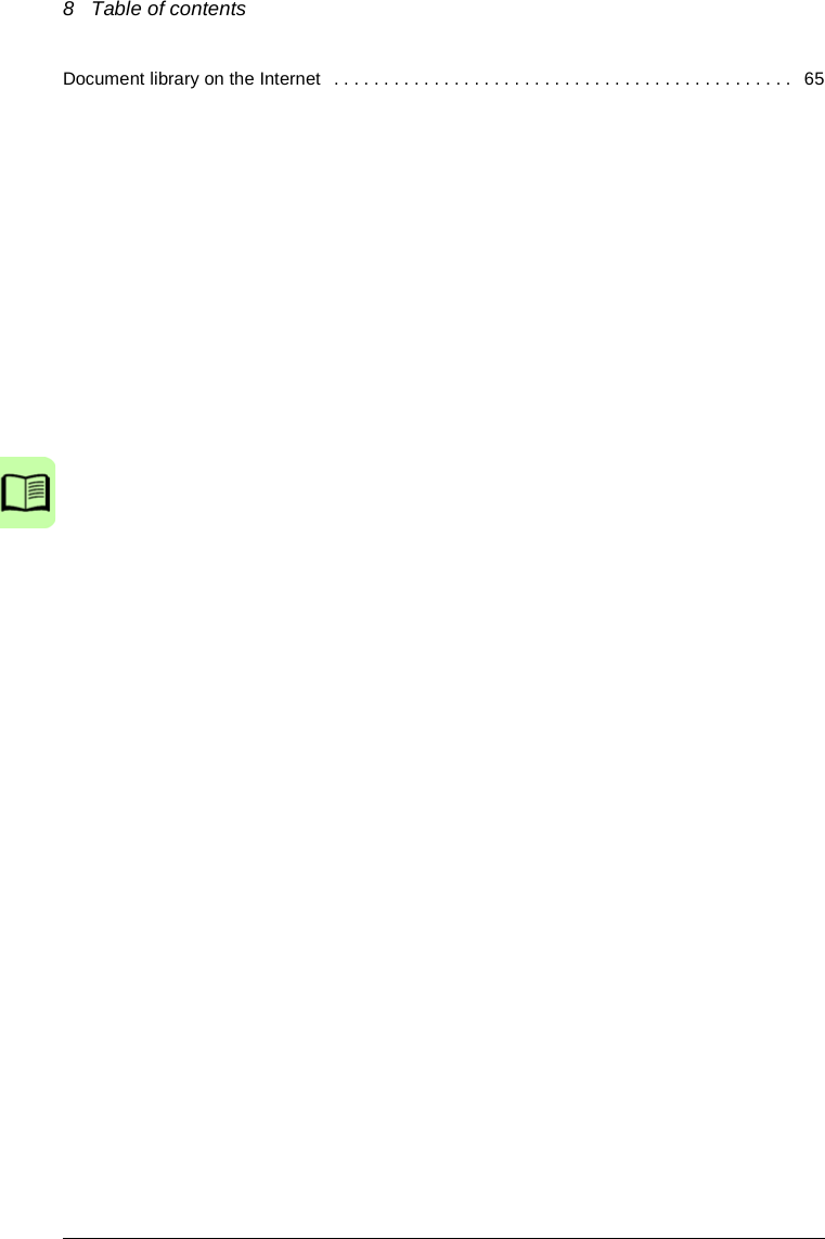
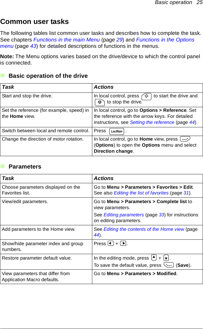
![62 Technical dataDimensions and weightDegrees of protectionMaterialsEnvironmental limitsWeight 130 gHeight, width and depthmm [in.]Degree of protection, attached to a driveIP55Separately IP20Enclosure PCB/ABSPackaging CardboardScreen PolycarbonateDisposal Do not dispose the control panel with municipal waste. Check local regulations for disposal of electronic products.Operation Storage TransportationInstallation site altitude 4000 m (13123 ft.) - -Air temperature -20 °C to +55 °C(-4 °F to 131 °F)-40 °C to +70 °C(-40 °F to 158 °F)-40 °C to +70 °C(-40 °F to 158 °F)Relative humidity 95% (non-condensing)Contamination levels (IEC 60721-3-3, IEC 60721-3-2, IEC 60721-1-3-1)3C3](https://usermanual.wiki/ABB-Drives/APWSERIES/User-Guide-2796476-Page-62.png)