ABB Enterprise Software 142402 802.11 b/g/n Radio Module User Manual
Tropos Networks, Inc. 802.11 b/g/n Radio Module
User Manual
Tropos 1410 Integration Guide
August 27, 2013
Part Number: 200453-00 Rev. E0

Page 2 of 16
08-July-13
Contents
Notices .......................................................................................................................................................... 3
Copyright Notice ....................................................................................................................................... 3
FCC Notice to Users and Operators .......................................................................................................... 3
Industry Canada Notice to users and operators: ...................................................................................... 4
Required labeling ...................................................................................................................................... 4
Introduction .................................................................................................................................................. 5
Connectivity to wired and wireless clients ............................................................................................... 5
Security ..................................................................................................................................................... 6
Tropos Control network management ..................................................................................................... 6
Integrating the Tropos 1410 ...................................................................................................................... 7
Handling the Tropos 1410 circuit board ................................................................................................ 8
Physical installation ................................................................................................................................... 8
Power ........................................................................................................................................................ 8
Communications interfaces ...................................................................................................................... 8
Ethernet .................................................................................................................................................... 8
Serial ......................................................................................................................................................... 9
USB port .................................................................................................................................................. 10
Pushbutton Switches .............................................................................................................................. 10
LEDs ......................................................................................................................................................... 10
Antennas ................................................................................................................................................. 11
Configuration .............................................................................................................................................. 11
Recommended Testing ............................................................................................................................... 12
Physical Installation and Packaging ........................................................................................................ 12
Communications and Connectivity Testing ............................................................................................ 13
Environmental Tests ............................................................................................................................... 13
Safety and Servicing Information ................................................................................................................ 15
Safety Guidelines .................................................................................................................................... 15
Servicing the Tropos 1410 ................................................................................................................... 15
Specifications .............................................................................................................................................. 16

Page 3 of 16
08-July-13
Notices
Copyright Notice
©2003-2013 Tropos Networks, Inc. All rights reserved. Tropos, Tropos Networks, PWRP, GridCom and
MetroMesh are registered trademarks of Tropos Networks, Inc.
Information contained herein is subject to change without notice. The only warranties for Tropos
products and services are set forth in the express warranty statements accompanying such products and
services. Nothing herein should be construed as constituting an additional warranty. Tropos shall not be
liable for technical or editorial errors or omissions contained herein.
This product includes technology protected by U.S. Patents 6,704,301; 6,965,575; 7,016,328; 7,031,293;
7,058,021; 7,362,737; 7,376,087; 7,382,778; 7,397,789; 7,450,552; 7,460,489; 7,489,932; 7,499,409;
7,505,426; 7,542,421; 7,551,562; 7,564,781; 7,564,862; 7,580,393; 7,580,705; 7,586,879; 7,649,866;
7,668,137; 7,688,808; 7,689,224; 7,697,504; 7,706,285; 7,720,499; 7,729,278; 7,769,040; 7,843,891;
7,924,749; 7,929,975; 7,957,337; 7,970,394; 7,983,225; 8,031,615; 8,036,130; 8,036,186, 8,054,784;
8,055,759; 8,064,404.
FCC Notice to Users and Operators
This device complies with Part 15 of the FCC Rules. Operation is subject to the following two conditions:
(1) this device may not cause harmful interference, and (2) this device must accept any interference
received, including interference that may cause undesired operation.
This equipment has been tested and found to comply with the limits for a Class B digital device,
pursuant to Part 15 of the FCC Rules. These limits are designed to provide reasonable protection against
harmful interference when the equipment is operated in a commercial environment. This equipment
generates, uses, and can radiate radio frequency energy and, if not installed and used in accordance
with the instruction manual, may cause harmful interference to radio communications. Operation of this
equipment in a residential area is likely to cause harmful interference, in which case the user will be
required to correct the interference at their own expense. If this equipment does cause interference to
radio or television reception, which can be determined by turning the equipment off and on, the user is
encouraged to correct the interference by using one of the following measures:
Reorient or relocate the receiving antenna.
Increase separation between the equipment and receiver.
Connect the equipment to an outlet on a circuit different from that to which the receiver is
connected.
Consult the dealer or an experienced radio/TV technician.
This Part 15 radio device operates on a non-interference basis with other devices operating at this
frequency. Any changes or modification to said product not expressly approved by Tropos Networks
could void the user's authority to operate this device.

Page 4 of 16
08-July-13
Industry Canada Notice to users and operators:
This Class B digital apparatus meets all requirements of the Canadian Interference Causing Equipment
Regulations. Operation is subject to the following two conditions: (1) this device may not cause harmful
interference, and (2) this device must accept any interference received, including interference that may
cause undesired operation.
Cet appareillage numérique de la classe B répond à toutes les exigences de l’interférence canadienne
causant des réglements d’équipement. L’opération est sujette aux deux conditions suivantes : (1) cet
dispositif peut ne pas causer l'interférence nocive, et (2) ce dispositif doit accepter n’importe quelle
interférence reçue, y compris l'interférence qui peut causer l’opération peu désirée.
This device has been designed to operate with the antennas listed. Antennas not included or having a
gain greater than 7.4 dBi in the 2.4 GHz band are strictly prohibited for use with this device. The
required antenna impedance is 50 Ohms.
Operation is subject to the following two conditions:
1. This device may not cause interference, and
2. This device must accept any interference, including interference that may cause undesired operation
of the device.
To reduce potential radio interference to other users, the antenna type and its gain should be so chosen
that the equivalent isotropically radiated power (EIRP) is not more than that permitted for successful
communication.
Required labeling
The Federal Communications Commission (FCC) and Industry Canada (IC) require equipment that
contains a Tropos 1410 to have a label on the outside of the product that shows the FCC and IC ID
numbers. The label should say the following:
Contains:
FCC ID: P9J-142402
IC: 4751A-142402

Page 5 of 16
08-July-13
Introduction
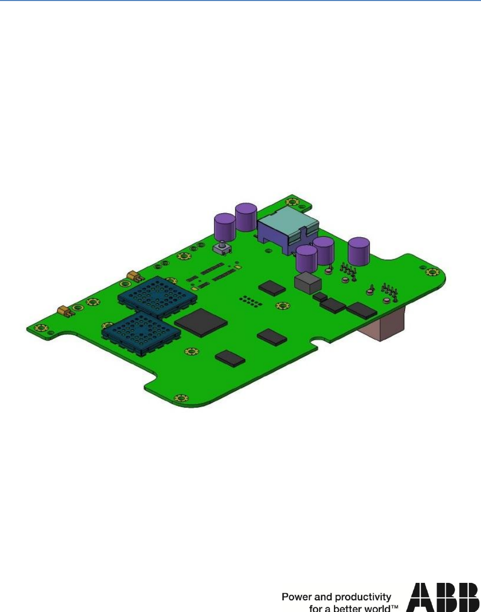
The Tropos 1410 is a compact, single-radio board designed to be integrated into devices that
participate in a Tropos mesh network. The Tropos 1410 allows large mesh networks to be built
economically, delivering mesh coverage and wireless- or wired-client connectivity for Smart Grid and
other multi-use applications. The Tropos 1410 can be ordered and configured to operate in either of
two modes:
As a bridge (14101040B {FCC} or 14101042B {ETSI}): A Tropos 1401-B can act as a wireless-to-
Ethernet or wireless-to-serial bridge to connect any Ethernet- or serial-enabled device to a
Tropos mesh network or to any 802.11b/g/n access point. Bridge operation requires Tropos
Software Release 7.9 or higher.
As a full-functioned mesh router (14103040B {FCC} or 14103042B {ETSI}): In mesh mode, a
Tropos 1410 can provide endpoint functions as well as support wireless clients and
downstream mesh links. Mesh operation requires Tropos Software Release 8.1 or higher.
The Tropos 1410 is optimized for embedded applications. While other Tropos routers are stand-alone
devices, the Tropos 1410 is designed to be integrated into other devices. For example, a Tropos 1410
can be integrated into a pole-mounted transformer, enabling the transformer to communicate health
and power quality data as well as function as a node in the mesh network.
Examples of devices that can use a Tropos 1410 for communications into a Smart Grid or Smart City
infrastructure are:
transformers
electric vehicle chargers
fuel cell control units
solar power inverters and controls
thermal energy storage units
intelligent traffic signals
control units for reclosers, regulators,
switch gear and capacitor banks
parking kiosks
Connectivity to wired and wireless clients
The Tropos 1410 supports both Ethernet and serial communications (RS-232 or RS-485, configurable)
for client devices. The serial interfaces support the DNP3 protocol. Connection to these ports is through
RJ-45 connectors. One RJ-45 connector supports the Ethernet port and power, and the second RJ-45
connector supports the serial interfaces and power (wiring diagrams for the RJ-45 connectors are shown
in Figure 1).
When operating in mesh mode the Tropos 1410 can support wireless clients. A wireless client can be
any device that supports 802.11b/g/n communications, including electric power distribution devices
such as reclosers, capacitor banks, and voltage regulators, and video cameras used for security or traffic
monitoring. Virtually any communicating device can be connected to the Tropos 1410.

Page 6 of 16
08-July-13
Security
The Tropos 1410 supports a high level of network security, including the following functions:
IPSec VPNs with tunnels to wired client
interfaces using AES
Authentication: WPA, WPA2, 802.11i, RADIUS,
802.1x (includes EAP-TLS, EAP-TTLS, PEAP)
Encryption: open, WEP, TKIP, AES-CCM
AES encryption of mesh and control traffic
FIPS 140-2 Level 2 compliant
NERC-CIP 002-0009 compliant
Multiple BSSIDs & ESSIDs (ESSID suppression)
HTTPS-based remote access
Password and Certificate-based HTTPS and
SSH Remote Access
Evil Twin Detection and Reporting
Integrated firewall:
Packet filtering based on TCP port, protocol, SA, DA
Peer-to-Peer Blocking
Client Access Control Lists
VPN filtering
Router Access Control
Denial of Service Attack Detection
Tropos Control network management
The Tropos 1410 is managed by Tropos’ industry leading network management, monitoring and
control application, Tropos Control. Tropos Control allows the network operator to monitor network
performance in real time and perform complex tasks such as network reconfiguration. It can function in
a stand-alone configuration or as part of a larger network management system using SNMP.
Page 7 of 16
08-July-13
Integrating the Tropos 1410
Integration of the Tropos 1410 requires the physical installation of the unit in a safe and reliable
manner; the correct powering the unit; the correct connection of the data interfaces and the correct
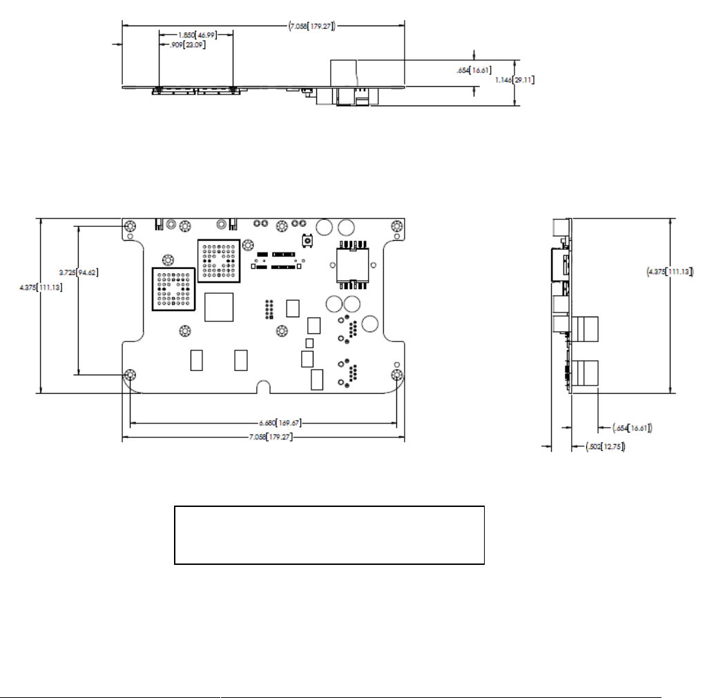
connection of the antennas. The following sections describe these steps. Figure 1 is an outline drawing
of the Tropos 1410 showing the location of components referred to in the following sections.
Figure 1
Tropos 1410 Components and Dimensions

Page 8 of 16
08-July-13
Handling the Tropos 1410 circuit board
Certain components used in the Tropos 1410 are sensitive to static electricity and can be damaged by
its discharge. The Tropos 1410 should be handled only in an ESD safe work area. The purpose of an
ESD safe work area is to prevent damage to sensitive components from spikes and static discharges.
These areas must be designed and maintained to prevent ESD damage.
The Tropos 1410 circuit board assembly must always be handled at properly designated work areas.
Stacking of Tropos 1410 circuit boards should be avoided to prevent physical damage.
Work areas should be kept clean and neat. Tropos 1410 circuit board assemblies should be handled by
the edges. Avoid touching the circuits or components.
Physical installation
The Tropos 1410 is a single board assembly. The board contains the processor, radio and connectors,
and components for conditioning and monitoring power.
The Tropos 1410 board is 6.680” long x 4.375” wide, 1.146” high. There are four mounting holes on
the Tropos 1410 designed for 4-40 screws (see Figure 1). The Tropos 1410 should be mounted on
stand-offs or bosses so that there is a minimum of 0.5” of clearance on all sides of the unit.
Power
The Tropos 1410 requires 11-50 VDC power. This power is then regulated by the Tropos 1410.
Power can be applied to the either the Ethernet or serial RJ-45 connector (see Figure 1). The pin
assignments for these ports are shown in Tables 1 and 2.
The Tropos 1410 does not use 802.3af or 802.3at signaling.
Communications interfaces
The Tropos 1410 supports Ethernet, serial and USB connections. There are two RJ-45 connectors on
the board. One is used for the Ethernet port. The other is used for the serial ports. There is one USB
Type A receptacle on the board.
Ethernet
The Ethernet port supports the Ethernet signals and power, as shown in table 1, below.

Page 9 of 16
08-July-13
pin
assignment
pin
assignment
1
TX +
5
Power +
2
TX -
6
RX -
3
RX +
7
Power -
4
Power +
8
Power -
Serial
The Tropos 1410 provides a dual serial interface on RJ-45 port 2. The integrator needs to configure the
Tropos 1410 for either RS-232 or RS-485 operation as shown in the current version of the Tropos User
Guide (user guides are available for specific Tropos software releases).
The serial interface can support multiple serial connections. The following configurations are supported:
One RS-232 connection (option 1 in Table 2)
One RS-485 connection (option 1 in Table 2)
One RS-232 connection and one RS-485 connections (option 2 in Table 2)
Two RS-232 connections (option 2 in Table 2)
The RJ-45 connector used for the serial ports has the pin assignments shown in Table 2, below:
pin
option 1 (one serial port)
option 2 (two serial ports)
1
RS232 TX or RS485 TXRX -
RS232 (port 2) TX or RS485 TXRX -
2
GND
GND
3
RS232 RX or RS485 TXRX +
RS232 (port 2) RX or RS485 TXRX +
4
Power +
not used
5
Power +
RS-232 (port 1) RX
6
not used
RS-232 (port 1) TX
7
Power -
not used
8
Power -
not used
Notes:
When using option 1 above for one RS-232 port, the port must be configured for port 2 (see
Tropos 1410 User Guide).
When the connector is used to support two serial ports (option 2) the connector cannot support
the power connections. In these cases power must be applied to the Ethernet port as shown in
Table 1.
The integrator must ensure that all cables have appropriate strain relief and do not place any
stress on the Tropos 1410’s connectors.
Table 1: Ethernet Port Pin Assignments
Table 2: Serial Port Pin Assignments
Page 10 of 16
08-July-13
USB port
The Tropos 1410 is equipped with a USB interface accessible through a Type A receptacle on the
board. Future software releases may provide support for devices such as GPS receivers.
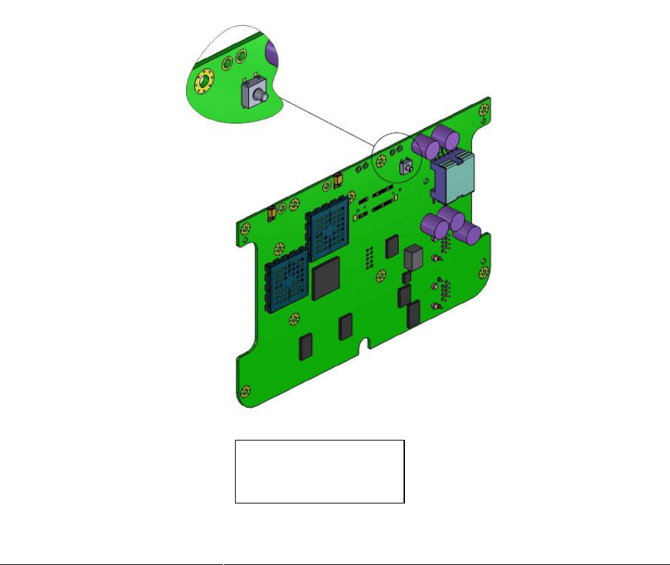
Pushbutton Switch
One pushbutton switch is mounted on the Tropos 1410 (see Figure 2). Its function is:
Software safe mode start. When SW 1 is depressed and held during the power on sequence the
Tropos 1410 software will start in safe mode.
LEDs
One LEDs are installed on the Tropos 1410 (on the bottom of the board). Its function is:
Blinks green when the radio is on.
Solid green when the Tropos 1410 is connected to a network
Figure 2
Switch Detail

Page 11 of 16
08-July-13
Antennas
Antennas for the Tropos 1410 can be purchased from Tropos or sourced by the integrator. The Tropos
1410 is designed for use with two omni-directional antennas.
The Tropos 1410 is FCC and Industry Canada approved for use only with omni-directional antennas
with a gain of 7.4 dBi or less. Please consult Tropos for any applications requiring other antennas.
In ETSI countries the typical maximum radiated power is +20dBm. 7.4dBi antennas can be used with an
ETSI 1410. Consult local regulations for the specific country in which the product will be used.
The Tropos 1410 uses a 2x2 MIMO (multiple-input, multiple-output) antenna configuration. The use of
two antennas is always recommended for optimal performance.
It is preferable to mount the antennas outside of the device enclosure, but antennas can be located
inside of an enclosure if the enclosure is non-metallic. Antennas should be mounted as high as possible
and can be mounted remotely from the device.
The standard antenna connectors on the Tropos 1410 board are MMCX connectors.
The connection from the antenna connectors on the Tropos 1410 and any antenna connectors on the
device should be made with low-loss coaxial cable. Tropos recommends LMR-240 or better cable.
Configuration
Configuration of the Tropos 1410 is covered in the current version of the Tropos Router User Guide for
Release 7.9 or higher.
Page 12 of 16
08-July-13
Recommended Testing
Tropos recommends that the OEM integrator perform the following tests to validate the integration of
the Tropos 1410 into their product. These are provided as guidelines to the OEM. Actual testing is the
responsibility of the OEM.
Physical Installation and Packaging
1. Verify that the Tropos 1410 is installed in the enclosure in accordance with the assembly
drawings and the installation guidelines and specifications provided in this document.
2. Verify that the antennas are properly connected to the SMA-antenna connectors.
3. Verify that the cable connecting the Tropos 1410 to the OEM equipment is properly installed.
4. Verify that the Tropos 1410 is powered when power is provided to the power supply board.
5. Verify that the external LED (if used) is properly wired and operates correctly.
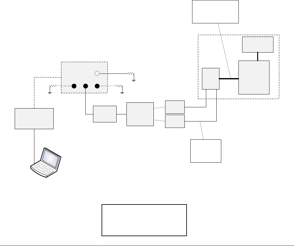
Figure 3 shows a typical test configuration
1410
OEM
communicating
device
coax cables to
antenna
connectors
DNP3 serial data plus
DC power or Ethernet
plus power
power supply
7320 gateway
RF combiner
60dB RF
attenuator
Communications
processor if
required
20 dB
attenuator
20 dB
attenuator
50Ω
50Ω
50Ω
Figure 3
Typical Test Configuration

Page 13 of 16
08-July-13
Communications and Connectivity Testing
Install an RF combiner and an attenuator as shown. Connect the attenuator to the center N-connector
on the Tropos 7320 router that will function as the gateway.
Using the configuration shown in Figure 3, perform the following tests:
Conduct a ping flood test from the computer to the Tropos 1410. Verify operation up to 25%
duty cycle.
Conduct tests from a communications controller (for example, a DNP3 master station) to the
OEM equipment to for all supported commands.
Verify that the console messages during Tropos 1410 boot up do not affect OEM
equipment (reboot the Tropos 1410 multiple times consecutively).
If serial communications is used verify that all the serial speeds (i.e. baud-rates 1200, 2400,
4800, 9600, 19200, 38400, 57600, 115200) on the Tropos 1410 work correctly with the OEM
equipment.
Verify that communications functionality does not get disrupted for extended period of time
when a Tropos 1410 roams to a different Tropos router (in the same subnet when Tropos
1410 retains the same IP address).
Verify that the Tropos 1410 reboots and upgrades do not disrupt the communications
functionality and end-to-end connectivity. Communications should resume automatically after a
reboot.
Verify the Tropos 1410 status page in the Configurator displays valid DNP3 local/remote
address and Tx/Rx packet information.
Verify that the Tropos 1410 can be rebooted using the configurator (remotely) and with the
reset button (locally).
Verify the Tropos 1410 can be reached via its rescue interfaces (wireless wlan0 and Ethernet
eth1) during standalone mode when it is not connected to any Tropos router.
Verify the Tropos 1410 and its wired clients can be configured in static and DHCP modes.
Environmental Tests
1. High and low temperature tests
The OEM equipment should be temperature tested, but within the specified
temperature range of the Tropos 1410
2. Cold start tests
Start up tests at the low rated operating temperature
3. Humidity tests
The OEM equipment should be humidity tested to its specifications, but within the
specified humidity range of the Tropos 1410
4. Temperature cycle tests per OEM requirements
5. Vibration tests per OEM requirements
6. Line voltage test
Operation between the specified input power range of the OEM equipment

Page 14 of 16
08-July-13
7. Surge test per OEM specifications
Voltage transient test per OEM specifications

Page 15 of 16
08-July-13
Safety and Servicing Information
The Federal Communications Commission (FCC) with its action in ET Docket 96-8 has adopted a safety
standard for human exposure to RF electromagnetic energy emitted by FCC certified equipment. The
Tropos 1410 meets the uncontrolled environmental limits found in OET-65 and ANSI C95.1, 1991.
Proper operation of this device according to the instructions found in this manual will result in user
exposure that is substantially below the FCC recommended limits.
To comply with FCC, Industry Canada and other national RF exposure safety requirements the antennas
for this device must be installed to provide a separation distance of at least 20 cm from persons and
shall not be co-located with other transmitting antennas except as shown in FCC/IC multi-transmitter
guidelines.
Safety Guidelines
Follow these guidelines to ensure safe operation of the router:
Do not touch or move the antennas while the unit is transmitting or receiving.
Do not hold any component containing a radio such that the antenna is very close to or touching
any exposed parts of the body, especially the face or eyes, while transmitting.
Do not operate the radio or attempt to transmit data unless the antenna is connected;
otherwise, the radio may be damaged.
Use in specific environments:
o Do not operate a portable transmitter near unshielded blasting caps or in an explosive
environment unless it is a type especially qualified for such use.
o The use of wireless devices in hazardous locations is limited to the constraints posed by
the safety directors of such environments.
o The use of wireless devices on airplanes is governed by the Federal Aviation
Administration (FAA).
o The use of wireless devices in hospitals is restricted to the limits set forth by each hospital.
Servicing the Tropos 1410
The Tropos 1410 has no user serviceable parts. For any service-related issues, contact Tropos
Customer Support (support@tropos.com).

Page 16 of 16
08-July-13
Specifications
Wireless
Networking
protocols supported
802.11 b/g/n
frequency band
2.400-2.483 GHz
modulation
(802.11b)
DSSS (DBPSK, DQPSK, CCK)
modulation
(802.11g/n)
OFDM (64-QAM, 16-QAM, QPSK,
BPSK)
media access
protocol
CSMA/CA with ACK
TX power
FCC: 12-27 dBm set in 1 dB units
ETSI: 5-20 dBm set in 1 dB units
RX sensitivity
-97 dBm at 1 Mbps
multi-antenna
system
2 TX, 2 RX MIMO
Radio ID
FCC: P9J-14240Ϯ
IC: 4751A-14240Ϯ
compatibility
802.11b/g/n
VLAN support
802q, ESSID and IP based tagging
addressing
static and dynamic addressing for
wireless and wired clients
quality of service
(QoS)
802.11e WMM
802.p/q with 4 queues per
VLAN and ESSID
802.p and DSCP
Wired Interfaces
Power
Ethernet
one 10/100Base-T
Serial
one RS-232 or
two RS-232 or
one RS-485 or
one RS232 and one RS485
DNP3
USB
one USB
connectors
two RJ-45(Ethernet and serial)
one USB Type A
unregulated input
11-55 VDC
power consumption
3 W typical
Security
Physical
authentication
WPA, WPA2, 802.11i, RADIUS,
802.1x (includes EAP-TLS, EAP-TTLS,
PEAP)
encryption
AES-128 (FIPS 140-2 compliant)
operating
temperature
-40 oC to +75 oC / -40 oF to +167 oF
storage
temperature
-40 oC to +85 oC / -40 oF to +185 oF
shock / vibration
ETSI 300-19-2-4; T41.E class 4M3
dimensions
6.680” L x 3.4.375” W x 1.146” H
weight
8 oz
antenna connectors
2 MMCX
antenna protection
integrated
electrical fast
transient immunity
EN61000-4-3 level 2
EMC field immunity
EN61000-4-2 level 2
ESD immunity
EN61000-4-2 (contact); level 3 (air)