ABB Enterprise Software 32101000 802.11 b/g Indoor Wi-Fi Cell Station User Manual 3210 Hardware Install
Tropos Networks, Inc. 802.11 b/g Indoor Wi-Fi Cell Station 3210 Hardware Install
User Manual
555 Del Rey Avenue
Sunnyvale, CA 94085
408.331.6800 Phone
408.331.6801 Fax
www.troposnetworks.com
Tropos 3210 Professional
Hardware Installation Guide
Part No - 200069-00 Rev A0
September 30, 2004

Tropos 3210 Wi-Fi Cell Hardware Installation Guide ii
Copyright 2004 by Tropos Networks
All rights reserved.
Rights reserved under the copyright laws of the United States.
RESTRICTED RIGHTS LEGEND
Use, duplication, or disclosure by the United States Government is subject to restrictions as set forth in subparagraph
(c)(1)(II) of the Rights in Technical Data and Computer Software clause at DFARS 252.227-7013.
Notwithstanding any other license agreement that may pertain to, or accompany the delivery of, this computer
software, the rights of the United States Government regarding its use, reproduction, and disclosure are as set forth in
the Commercial Computer Software-Restricted Rights clause at FAR52.227-19.
IMPORTANT NOTE TO USERS
This software is provided by Tropos Networks, Inc. as is and any express or implied warranties, including, but not
limited to, implied warranties of merchantability and fitness for a particular purpose are disclaimed. In no event shall
Tropos Networks, or its affiliates, subsidiaries or suppliers be liable for any direct, indirect, incidental, special,
exemplary, or consequential damages (including, but not limited to, procurement of substitute goods or services; loss
of use, data or profits; or business interruption) however caused and on any theory of liability, whether in contract,
strict liability, or tort (including negligence or otherwise) arising in any way out of the use of this software, even if
advised of the possibility of such damage.
Tropos reserves the right to make changes without further notice to any products herein.

Tropos 3210 Wi-Fi Cell Hardware Installation Guide iii
Contents
1 Introduction . . . . . . . . . . . . . . . . . . . . . . . . . . . . . . . . . . . . . . . . . . . . . . . . . 1
Notice to Users . . . . . . . . . . . . . . . . . . . . . . . . . . . . . . . . . . . . . . . . . . . . . . . 1
FCC Notice to Users and Operators . . . . . . . . . . . . . . . . . . . . . . . . . . . . . . 1
Taiwan DGT Telecommunications Act Notice to Users and Operators . . . 2
Antenna Options . . . . . . . . . . . . . . . . . . . . . . . . . . . . . . . . . . . . . . . . . . . . . 3
FCC Approved Antennas for US and Canada. . . . . . . . . . . . . . . . . . . . . . . 3
DGT Approved Antennas for Taiwan . . . . . . . . . . . . . . . . . . . . . . . . . . . . . 3
Tropos Wireless Networking. . . . . . . . . . . . . . . . . . . . . . . . . . . . . . . . . . . . 3
2 Pre-Installation Guidelines . . . . . . . . . . . . . . . . . . . . . . . . . . . . . . . . . . . . . 6
Selecting Locations . . . . . . . . . . . . . . . . . . . . . . . . . . . . . . . . . . . . . . . . . . . 6
Basic Guidelines . . . . . . . . . . . . . . . . . . . . . . . . . . . . . . . . . . . . . . . . . . . . . 6
Installation in Air-Handling Environments. . . . . . . . . . . . . . . . . . . . . . . . . 7
Antenna Options. . . . . . . . . . . . . . . . . . . . . . . . . . . . . . . . . . . . . . . . . . . . 7
Site Surveys . . . . . . . . . . . . . . . . . . . . . . . . . . . . . . . . . . . . . . . . . . . . . . . 7
Wireless Coverage and Range . . . . . . . . . . . . . . . . . . . . . . . . . . . . . . . . 7
RF Planning Guidelines . . . . . . . . . . . . . . . . . . . . . . . . . . . . . . . . . . . . . . 8
Preparing for Installation . . . . . . . . . . . . . . . . . . . . . . . . . . . . . . . . . . . . . . . 8
Unpacking . . . . . . . . . . . . . . . . . . . . . . . . . . . . . . . . . . . . . . . . . . . . . . . . 8
Items Included with Tropos 3210 Wi-Fi Cell. . . . . . . . . . . . . . . . . . . . . . . 9
Required Tools and Supplies for Installation . . . . . . . . . . . . . . . . . . . . . . 9
3 Installing the Tropos 3210 Wi-Fi Cell . . . . . . . . . . . . . . . . . . . . . . . . . . . . 11
Wall Mounting Instructions . . . . . . . . . . . . . . . . . . . . . . . . . . . . . . . . . . . . 11
Connecting Power and LAN . . . . . . . . . . . . . . . . . . . . . . . . . . . . . . . . . . . 15
4 Operating the Tropos 3210 Wi-Fi Cell . . . . . . . . . . . . . . . . . . . . . . . . . . . 18
Operational Lights on the Tropos 3210 Wi-Fi Cell . . . . . . . . . . . . . . . . . 18
Operating the Wi-Fi Cell. . . . . . . . . . . . . . . . . . . . . . . . . . . . . . . . . . . . . . . 19
Preparing the Configuration Utility. . . . . . . . . . . . . . . . . . . . . . . . . . . . . . . 20

Tropos 3210 Wi-Fi Cell Hardware Installation Guide iv
Accessing the Configuration Utility . . . . . . . . . . . . . . . . . . . . . . . . . . . . . . 21
Safety Information for the Tropos 3210 Wi-Fi Cell . . . . . . . . . . . . . . . . . 22
Guidelines to insure safe operation of the Tropos 3210 Wi-Fi cell. . . . . 22
Use in specific environments . . . . . . . . . . . . . . . . . . . . . . . . . . . . . . . . . 23
Antenna use guidelines . . . . . . . . . . . . . . . . . . . . . . . . . . . . . . . . . . . . . 23
Service Instructions . . . . . . . . . . . . . . . . . . . . . . . . . . . . . . . . . . . . . . . . . . 23

Tropos 3210 Wi-Fi Cell Hardware Installation Guide 1
1Introduction
The instructions contained in this guide are intended for a trained technical professional
audience. Operational and network configuration information for the Tropos 3210 Wi-Fi cell can
be found in the Tropos Networks Configuration Guide.
This chapter contains important information about using Tropos equipment, antenna options,
and background regarding Tropos wireless networking.
Notice to Users
FCC Notice to Users and Operators
The Tropos 3210 Wi-Fi cell complies with Part 15 of the FCC rules. Operation of the Tropos
3210 Wi-Fi cell is subject to the following two conditions:
1. This device may not cause harmful interference, and
2. This device must accept any interference received, including interference that may cause
undesired operation.
This equipment has been tested and found to comply with the limits of a Class B digital device,
pursuant to Part 15 of the FCC Rules. These limits are designed to provide reasonable protection
against harmful interference when the equipment is operated in an office environment. This
equipment generates, uses and radiates radio frequency energy, and if not installed and used in
accordance with the instructions, the device may cause harmful interference. However, there is
no guarantee that interference will not occur. If this equipment does cause interference to radio
or television reception, which can be determined by turning the equipment off and on, the user is
encouraged to correct the interference by using one of the following measures:
Reorient or relocate the receiving antenna.
Increase separation between the equipment and receiver.
Connect the equipment to an outlet on a circuit different from that to which the receiver is
connected.
Consult the dealer or an experienced radio/TV technician.

Chapter 1 Introduction
Tropos 3210 Wi-Fi Cell Hardware Installation Guide 2
Caution
This Part 15 radio device operates on a non-interference basis with other devices
operating at this frequency. Any changes or modification to said product not expressly
approved by Tropos Networks could void the user's authority to operate this device.
Taiwan DGT Telecommunications Act Notice to Users and Operators
Warning
It is illegal to modify the construction of this product. Modifying the operating frequency or
enhancing the transmit output power through the use of external amplifiers or other
equipment is specifically disallowed by the “Telecommunications Act.”
Warning
This device is for indoor use only with conditions that no harmful interference to authorized
radio stations results from the operation of this device. This device shall not influence aircraft
security and/or interfere with legal communications as defined in the “Telecommunications
Act.” If this device is found to cause interference, the operator of this equipment shall cease
operating this device immediately until no interference is achieved.
低功率電波輻性電機管理辦法
第十四條經型式認證合格之低功率射頻電機,非經許可,公司、商號或使
用者均不得擅自變更頻率、加大功率或變更原設計之特性及功能。
第十七條低功率射頻電機之使用不得影響飛航安全及干擾合法通信;經發
現有干擾現象時,應立即停用,並改善至無干擾時方得繼續使用。
前項合法通信,指依電信規定作業之無線電信。低功率射頻電機須忍受合法通信
或工業、科學及醫療用電波輻射性電機設備之干擾。

Chapter 1 Introduction
Tropos 3210 Wi-Fi Cell Hardware Installation Guide 3
Note
This device must be installed by trained professional, value added reseller or systems
integrator who is familiar with RF cell planning issues and the regulatory limits defined by the
Taiwan government “Telecommunications Act” for RF exposure, specifically those limits
outlined in Telecom Technical Regulations RTTE01 and LP002.
Antenna Options
FCC Approved Antennas for US and Canada
The cell can be configured with one of the following antenna options. (Antennas are ordered
separately.)
AN025004 — Indoor 2.5 dBi omni directional antenna cable attached;
SMA (male) connector
AN040004 — Indoor 4.0 dBi directional patch antenna cable attached;
SMA (male) connector
Note
The Tropos 3210 Wi-Fi cell must be installed by a trained professional, value added reseller,
or systems integrator who is familiar with RF cell planning issues and the regulatory limits
defined by the FCC for RF exposure; specifically those limits outlined in sections 1.1307.
DGT Approved Antennas for Taiwan
The cell can be configured with one of the following antenna options. (Antennas are ordered
separately.)
AN025004 — Indoor 2.5 dBi omni directional antenna cable attached;
SMA (male) connector
AN040004 — Indoor 4.0 dBi directional patch antenna cable attached;
SMA (male) connector
Tropos Wireless Networking
To better understand how a Tropos wireless networking system works, it is helpful to compare it
typical 802.11g systems. Typical 802.11g access points must be “hardwired” to your internal
network. To install a typical access point, you connect the Ethernet port on the access point to a
hub or switch port on your internal network. Each access point acts as an extension to your wired
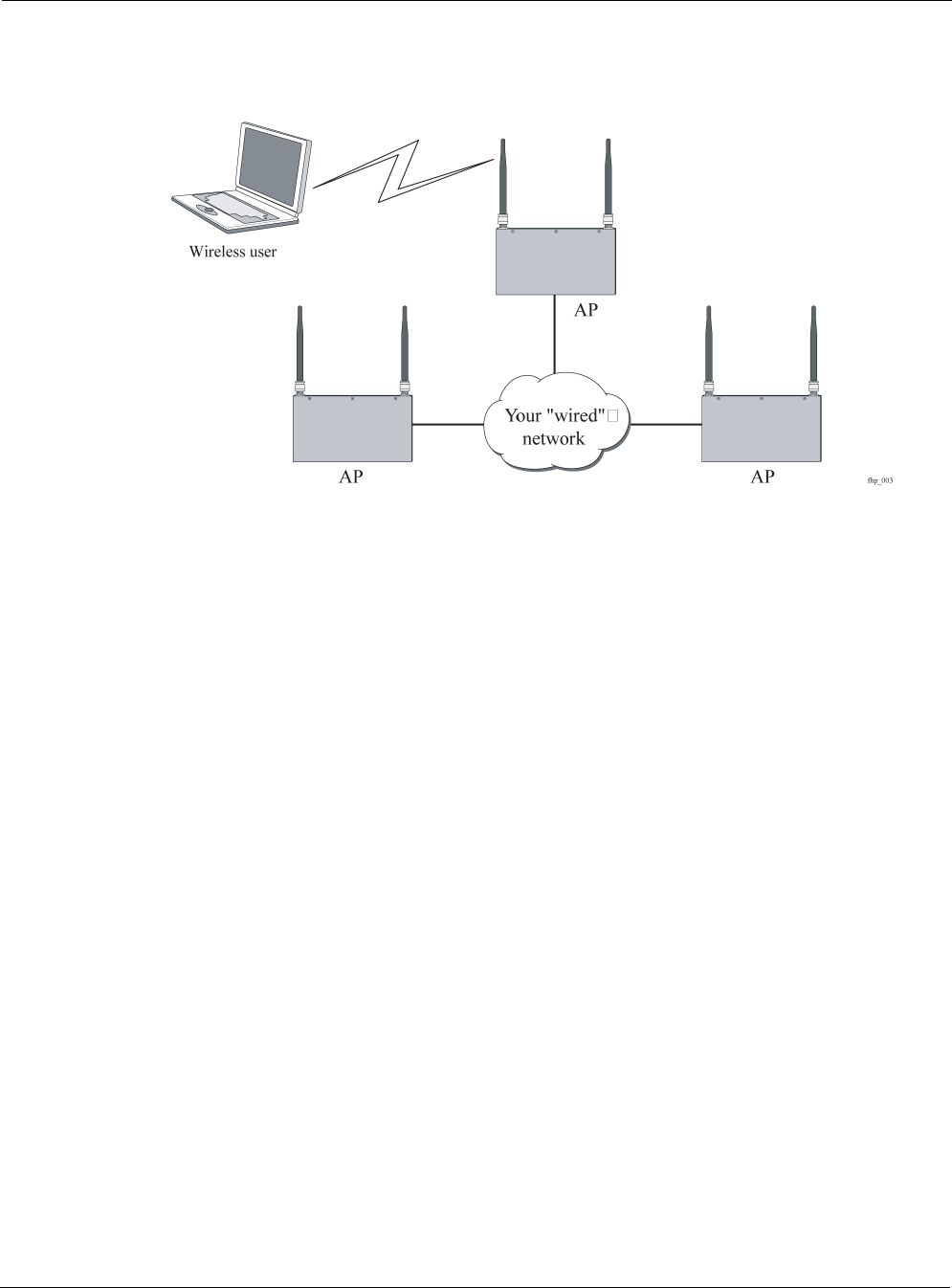
Chapter 1 Introduction
Tropos 3210 Wi-Fi Cell Hardware Installation Guide 4
network by serving as a bridge, connecting clients to your internal network. An sample network
is shown in the next figure.
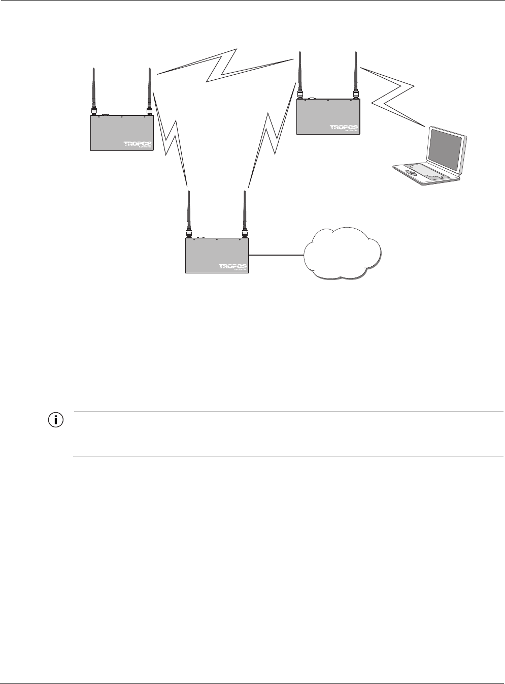
Tropos networks are designed to significantly reduce the wired connectivity requirements of
typical 802.11 networks. Only a small number of Tropos Wi-Fi cells, configured as gateways,
must be hardwired to your internal network. In fact, for some wireless networks, only one
Tropos Wi-Fi gateway may be needed. Additional gateways may be desired provide redundancy
and additional bandwidth for larger wireless networks.
Non-wired Tropos Wi-Fi cells (Tropos Wi-Fi nodes) function independently to form large,
routed wireless networks. You can expand the wireless network simply by installing and
providing power to the Tropos Wi-Fi nodes. Freed from the need to connect every cell to the
wired network, you can build large, routed wireless networks covering areas that are
traditionally hard to reach. As shown in the next figure, the wireless Tropos Wi-Fi nodes provide
service to clients while connecting wirelessly to the Tropos Wi-Fi gateway and on to the wired
network.
Chapter 1 Introduction
Tropos 3210 Wi-Fi Cell Hardware Installation Guide 5
Tropos Wi-Fi nodes automatically configure themselves to form clusters around each wired
gateway. No user intervention is required and no knowledge of routing protocols is necessary to
configure your network. Each device needs some basic configuration information (ESSID, WEP
Key), but other than that, your wireless network configures itself and performs all routing
functions in the background. Even the IP addresses on the wireless network are automatically
configured and preset at the factory, enabling true “plug-and-play” network configurations.
Note
Refer to the Tropos Networks Configuration Guide for complete software configuration
information.
Proceed to Chapter 3, “Installing the Tropos 3210 Wi-Fi Cell,” for complete installation
instructions.
trp_B004
Wireless user
Tropos
3210 node
Tropos
3210 gateway
Tropos
3210 node
Your "wired"
network

Tropos 3210 Wi-Fi Cell Hardware Installation Guide 6
2Pre-Installation Guidelines
This chapter presents guidelines for installing the Tropos 3210 Wi-Fi cell. It includes the
following information:
Selecting Locations
Basic Guidelines
Preparing for Installation
Selecting Locations
When installing your Tropos 3210 Wi-Fi cell, keep in mind that 10/100 Base-T Ethernet using
category 5 network cabling has a 300 meter distance limitation. The Tropos 3210 Wi-Fi cell
Ethernet duplex settings may be configured to operate at 10 Base-T, which has a distance
limitation of 370 meters.
Basic Guidelines
Tropos 3210 Wi-Fi cells are radio devices, and as such, they are susceptible to common causes
of interference that can reduce throughput and range. To ensure the best possible performance,
follow these basic guidelines:
Install the antennas in an area where trees, buildings, and large steel structures such as
shelving units, bookcases, and filing cabinets do not obstruct radio signals to and from the
antenna. Locating the antennas for direct line-of-sight operation is best.
Install the cells away from microwave ovens or other devices operating in the 2.4 GHz
frequency range. Microwave ovens operate on the same frequency as the cell and can cause
signal interference.
Install the cells away from other possible sources of 2.4 GHz WLAN interference, such as
cordless phones, home spy cameras, frequency hopping (FHSS) and DSSS LAN
transceivers (non-802.11g), electronic news gathering video links, radars, amateur radios,
land mobile radio services, local government sites (such as law enforcement), fixed
microwave services, local TV transmission and private fixed point transmitters).

Chapter 2 Pre-Installation Guidelines
Tropos 3210 Wi-Fi Cell Hardware Installation Guide 7
Installation in Air-Handling Environments
Tropos 3210 Wi-Fi cells are UL2043 certified which means that they are suitable for use in air-
handling spaces.
Antenna Options
Tropos 3210 Wi-Fi cells support external antennas with omni-directional or directional
capabilities. Omni-directional antennas are best for systems requiring a signal distribution in
more than one direction. High-gain directional antennas are best suited for covering longer
distances in a fixed direction.
Note
Only use antennas supplied by Tropos. Operating a cell with a non-qualified antenna may
be in violation of FCC Rules Part 15.203(c), Code of Federal Regulations, Title 47.
Site Surveys
Because of differences in component configuration, placement, and physical environment, every
network application is a unique installation. Before installing multiple Tropos 3210 Wi-Fi cells,
perform a site survey to determine the optimal use of networking components and to maximize
range, coverage, and network performance.Consider the following operating and environmental
conditions when performing a site survey:
Data rates—Sensitivity and range are inversely proportional to data bit rates. The
maximum radio range is achieved at the lowest workable data rate. A decrease in receiver
threshold sensitivity occurs as the radio data increases.
Antenna type and placement—Proper antenna configuration is a critical factor in
maximizing radio range. As a general rule, range increases in proportion to antenna height
and gain.
Physical environment—Clear or open areas provide better radio range than closed or filled
areas. Also, the less cluttered the operating environment, the greater the range.
Obstructions—A physical obstruction, such as a building or tree, can block or hinder
communication between Tropos 3210 Wi-Fi cells. Avoid locating the antennas in a location
where there is an obstruction between the sending and receiving antennas.
Building materials—Radio penetration is greatly influenced by the building material used
in construction. For example, drywall construction allows greater range than concrete
blocks. Metal or steel construction is a barrier to radio signals.
For additional planning information, refer to the Tropos Networks System Design Guidelines.
Wireless Coverage and Range
Tropos wireless network operation depends upon multi-hop data transfers across nodes to
provide connectivity to a Tropos Wi-Fi gateway. These gateways need to be placed close

Chapter 2 Pre-Installation Guidelines
Tropos 3210 Wi-Fi Cell Hardware Installation Guide 8
enough to each other so that one device can communicate with other Tropos 3210 Wi-Fi cells
over the RF wireless interface. However, clustering too many cells together within a small
geographic area may create a situation in which the cells are subject to excessive interference.
This can adversely affect network performance and throughput.
Each Tropos 3210 Wi-Fi cell should have a partial overlapping coverage area with at least one
other cell. As a general rule, placing a Tropos 3210 Wi-Fi cell so that it has partial overlapping
coverage area with two other cells provides adequate network redundancy while also mitigating
interference.
RF Planning Guidelines
Tropos wireless routing technology is embedded in each Tropos Wi-Fi cell, allowing each cell to
work in almost any environment and with a wide range of network topologies. To maximize
coverage range, locate the cell in wireless-friendly areas. Try not to place them in areas that can
block or interfere with transmission. 802.11g devices transmit in the 2.4 GHz frequency
spectrum. This spectrum is shared by devices such as microwave ovens, portable phones,
intercom systems and wireless alarm systems. Place each cell in a location at least 15 to 20 feet
from any other transmitter to prevent the possibility of interference.
Locating your Tropos 3210 Wi-Fi cells high on a wall or hanging from a ceiling is a good start.
This allows transmission over the entire environment or office space with minimal blocking
objects. If you are trying to cover an outdoor area from inside a building, place cells in front of
non-metallic coated windows, or close to the outside walls of the building.
Preparing for Installation
Unpacking
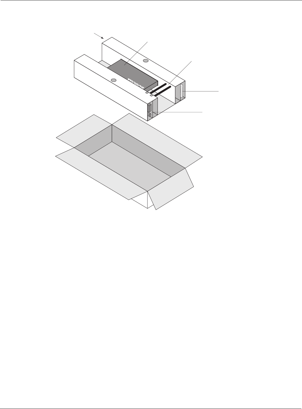
Carefully unpack the Tropos 3210 Wi-Fi cell shipping box. The power adapter box and the
mounting hardware bag are contained in the cardboard holder for the unit, as shown in the next
figure. Do not discard the bag or box.
Chapter 2 Pre-Installation Guidelines
Tropos 3210 Wi-Fi Cell Hardware Installation Guide 9
Items Included with Tropos 3210 Wi-Fi Cell
Each Tropos 3210 Wi-Fi cell is shipped with the following items:
Four 1-inch drywall screws
Four 1-inch drywall anchors
Two right angle mounting brackets
One Tropos 3210 Wi-Fi cell
One AC/DC power converter, for use at 100 to 240 VAC
Two antennas (optional)
One 0.5 ml capsule of Loctite® Threadlocker 242 (used to bond antenna connectors to unit)
Four #6–32 screws - phillips head
Four #6–32 screws - tamper-resistant TORX® T10-H
Required Tools and Supplies for Installation
You need the following tools and supplies to complete the Wi-Fi cell installation:
Phillips-head screwdriver
fh
p
_002
Mounting hardware bag
Large antennas
(if present)
Power adapter
box
Tropos 3210
Small antennas
(if present)

Chapter 2 Pre-Installation Guidelines
Tropos 3210 Wi-Fi Cell Hardware Installation Guide 10
Drill with 3/16 inch diameter drill bit
Stud finder
Tamper-resistant TORX key driver T10-H (if tamper-resistant TORX screws are used)
A non-switched, 100 to 240 Volt 15 Amp duplex power outlet within five feet of the Tropos
3210 Wi-Fi cell mounting location
A wood or plasterboard wall with adequate clearance to mount the Tropos 3210 Wi-Fi cell.
Note
To comply with FCC RF exposure limits, Tropos 3210 Wi-Fi cell dipole antennas should be
located at a minimum distance of 7.9 inches (20cm) or more from people.

Tropos Networks 3210 Hardware Installation Guide 11
3Installing the Tropos 3210 Wi-Fi Cell
This chapter describes how to install the Tropos 3210 Wi-Fi cell, and includes the following
information:
Wall Mounting Instructions
Connecting Power and LAN
Caution
Tropos 3210 Wi-Fi cell dipole antennas should be located at a minimum distance of 7.9
inches (20cm) or more from people. This is the safe distance specified by the FCC for
RF exposure limits.
Wall Mounting Instructions
The Tropos 3210 Wi-Fi cell can be wall-mounted in the following three ways:
Edge mounted, as shown in the figure on page 12
Flat mounted, as shown in the figure on page 13
Secure mounted, as shown in the figure on page 14
Chapter 3 Installing the Tropos 3210 Wi-Fi Cell
Tropos Networks 3210 Hardware Installation Guide 12
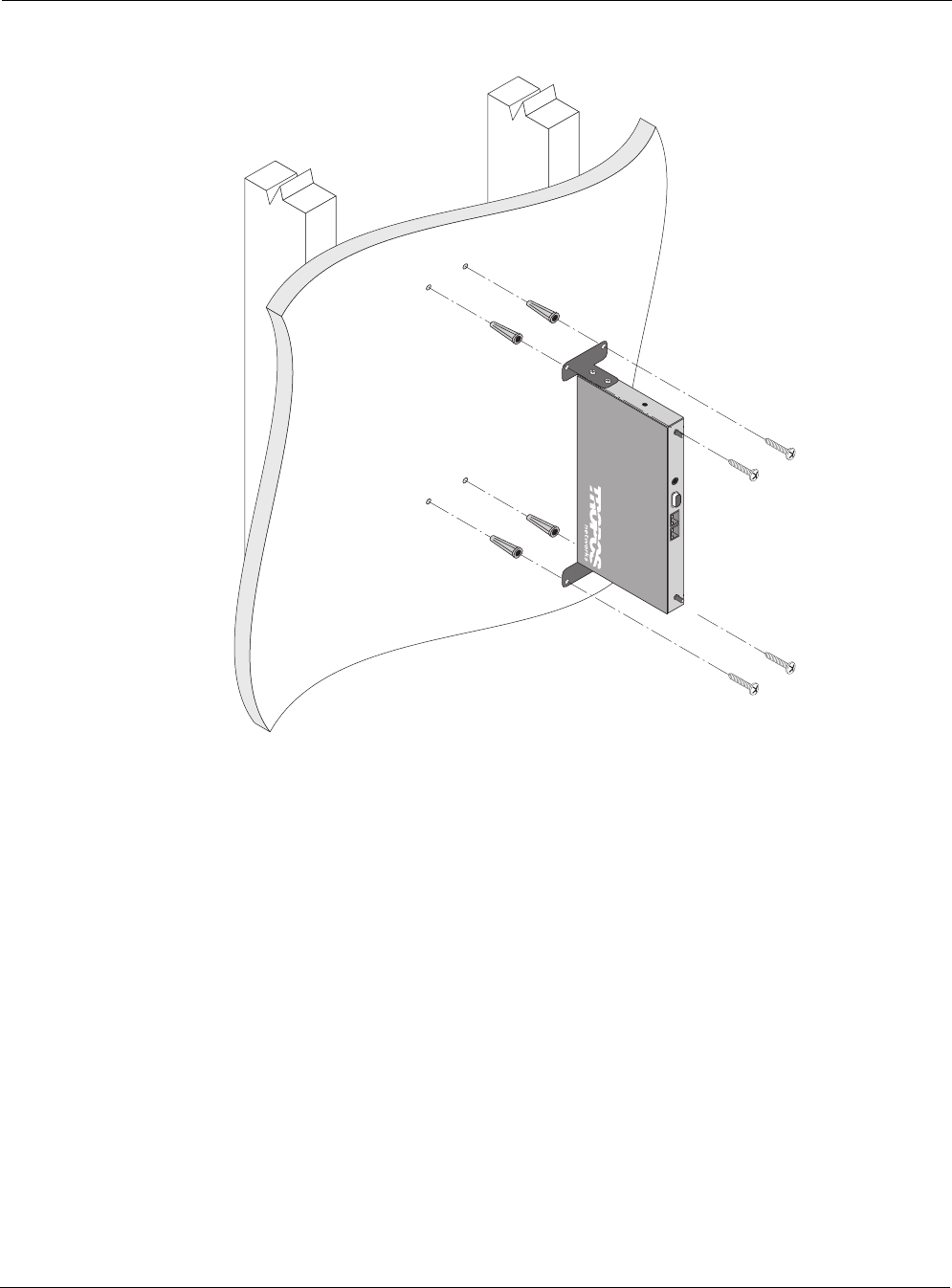
Edge Mounting
trp_005
Chapter 3 Installing the Tropos 3210 Wi-Fi Cell
Tropos Networks 3210 Hardware Installation Guide 13
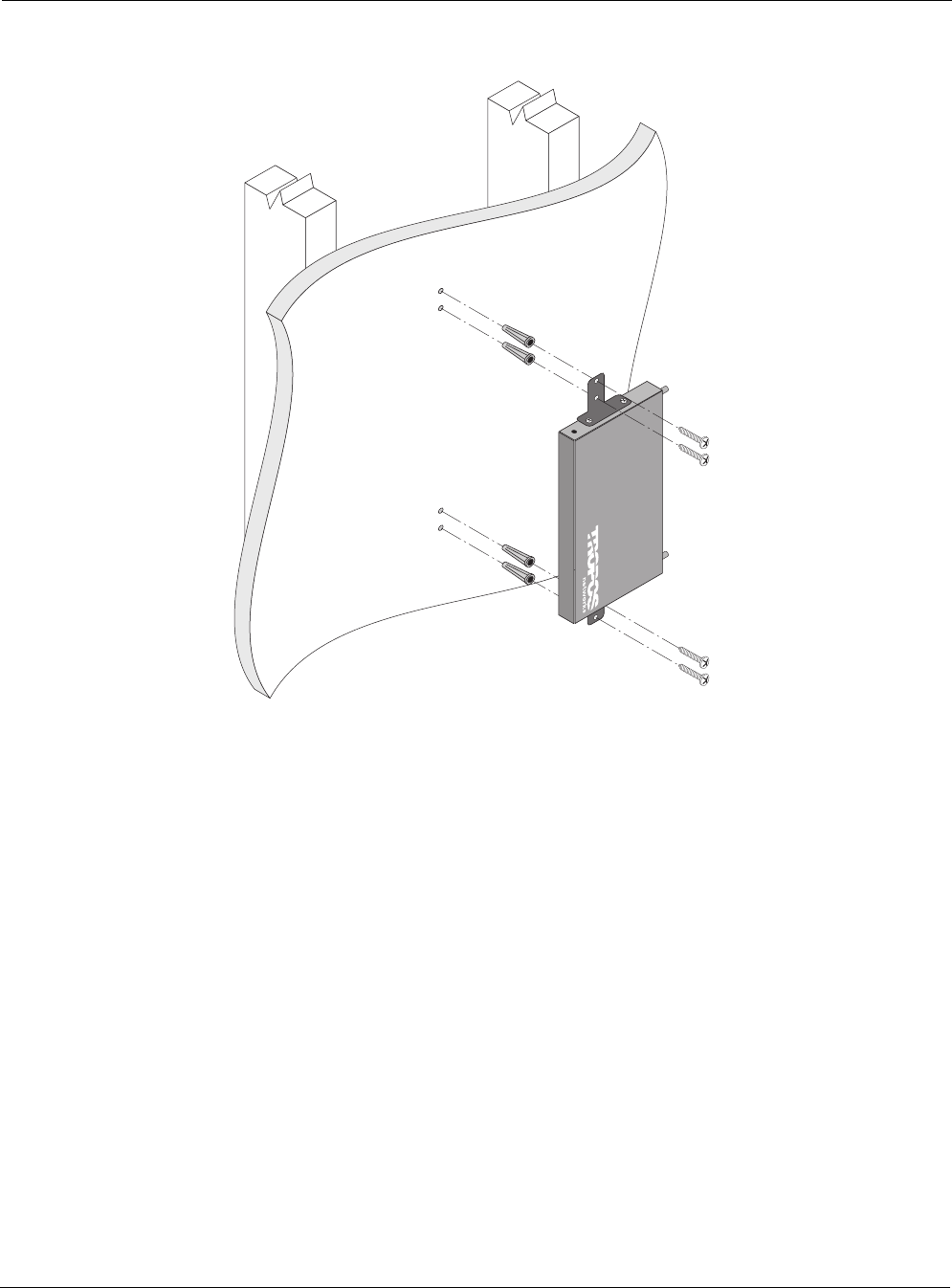
Flat Mounting
trp_006
Chapter 3 Installing the Tropos 3210 Wi-Fi Cell
Tropos Networks 3210 Hardware Installation Guide 14
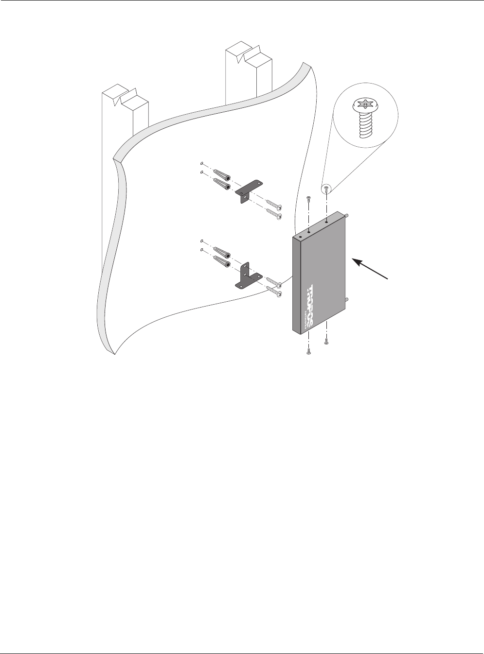
Secure Mounting
To mount Tropos 3210 Wi-Fi cell on a wall
1. Select a mounting orientation for the cell.
2. Locate two studs on the wall using the stud finder. The cell should be mounted midway
between the two studs.
3. Drill four holes in the wall to accommodate the mounting brackets.
4. Push the four wall anchors into the four holes.
5. Screw the mounting brackets to the wall.
6. Screw the cell to the mounting brackets.
7. Perform a trial installation of the antennas or antenna cables, depending on your installation.
trp_011
After fastening
brackets to wall,
use Torx screws
to attach brackets
to cell
Chapter 3 Installing the Tropos 3210 Wi-Fi Cell
Tropos Networks 3210 Hardware Installation Guide 15
8. Once you are satisfied with the trial placement of the antennas or antenna cables, remove the
antenna connections from the cell and apply two drops of Loctite Threadlocker 242 to the
antenna connector thread.
9. Install the antenna or antenna cables.
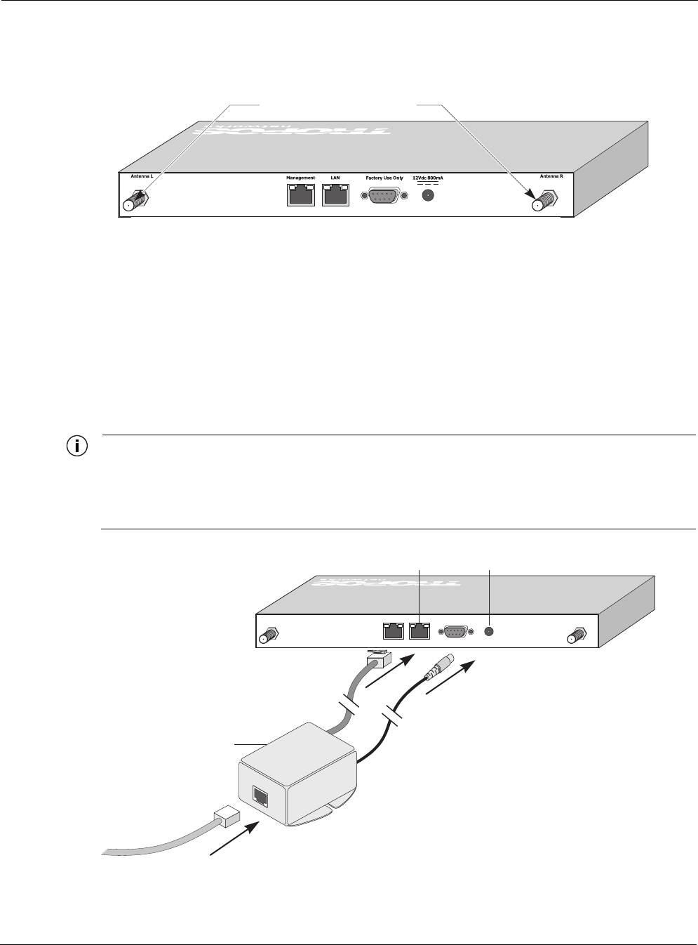
Connecting Power and LAN
The LAN port on your Tropos 3210 Wi-Fi cell is not compatible with the IEEE 802.3af
standard. If you plan to use Power over Ethernet (PoE) to power the cell, an external PoE splitter
device is required (see the next figure).
Note
When the Tropos 3210 Wi-Fi cell is installed in a plenum or air-handling space, the cables
employed should be suitable under NEC article 800-50 and NFPA 262 and marked
accordingly, for use in plenums and air-handling spaces with regard to smoke propagation,
such as CL2-P, CL3-P, MPP or CMP.
tr
p
_007
Apply 2 drops of Loctite here
trp_012
LAN port
PoE splitter
(not supplied by Tropos)
12Vdc
jack
Splitter data/PoE
in
Splitter data out
Splitter Vdc out
Chapter 3 Installing the Tropos 3210 Wi-Fi Cell
Tropos Networks 3210 Hardware Installation Guide 16
Note
If you use the PoE option, make sure that the power sourcing device is IEEE 802.3 af-
compliant.
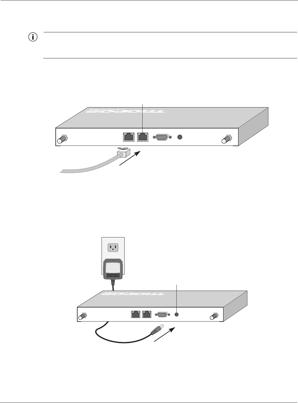
Follow these steps to connect a Tropos 3210 Wi-Fi cell to your network:
1. Attach a category 5 twisted pair patch cable to the Ethernet port labeled LAN on the cell.
2. Connect the other end directly into your PC or laptop or to your internal network. See
“Selecting Locations” on page 6 for more information on where to connect the cell to your
internal network.
3. If you are not using the PoE option, connect the supplied AC/DC adapter to the cell and plug
the power adapter into a standard 100 to 240VAC power outlet, as shown in below. Wait 2
minutes for the cell to boot.
trp_008
LAN port
(can accept power to unit)
trp_009
12Vdc
jack

Chapter 3 Installing the Tropos 3210 Wi-Fi Cell
Tropos Networks 3210 Hardware Installation Guide 17
Note
The DB-9 connector marked Factory Use Only is a serial port used at the factory to
configure settings and software for the Tropos 3210 Wi-Fi cell. It is not necessary to use this
port for configuration.
Tropos 3210 Wi-Fi Cell Hardware Installation Guide 18
4Operating the Tropos 3210 Wi-Fi Cell
This chapter contains instructions and information for operating the Tropos 3210 Wi-Fi cell. It
contains the following information:
Operational Lights on the Tropos 3210 Wi-Fi Cell
Operating the Wi-Fi Cell
Safety Information for the Tropos 3210 Wi-Fi Cell
Service Instructions
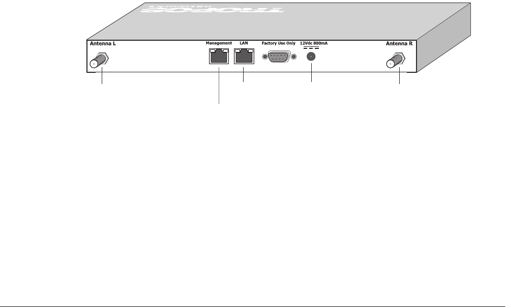
Operational Lights on the Tropos 3210 Wi-Fi Cell
The next figure shows the names and locations of the connections found on the front panel of the
Tropos 3210 Wi-Fi cell. The panel includes antenna connectors, Reset button, power
connection, and Management and LAN ports. The LEDs for the management port and the LAN
port show whether connectivity has been established over those ports.
trp_091
Left antenna Right antenna
Management
port
12Vdc
jack
LAN
port
Chapter 4 Operating the Tropos 3210 Wi-Fi Cell
Tropos 3210 Wi-Fi Cell Hardware Installation Guide 19
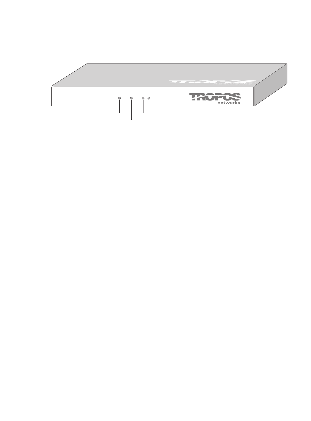
The next figure shows the names and locations of the LEDs found on the rear panel of the
Tropos 3210 Wi-Fi cell. The green Power LED is located towards the left, and remains on while
the unit is powered. The red signal strength LED shows the strength of the network connection.
The Net LED flashes to indicate network traffic, and the Disk LED flashes when the flash boot
memory is accessed.
Booting sequence for the Tropos 3210 Wi-Fi cell
1. The green power LED turns on, the signal strength LED remains off.
2. When the Tropos 3210 Wi-Fi cell begins to obtain network settings, the signal strength LED
turns solid red.
3. Once the Tropos 3210 Wi-Fi cell has obtained network settings and is fully operational, the
red signal strength LED begins flashing, and continues to do so during normal operation.
If there is no connection, the LED is solid red. If there is a connection, the speed of the blinking
red light indicates its strength, with faster blinking indicating a stronger connection.
Operating the Wi-Fi Cell
This section describes the steps required to properly configure your Tropos 3210 Wi-Fi cell for
use. For complete configuration information, see the Tropos Networks User Guide.
trp_090
Power Net
Signal
strength
Disk
Chapter 4 Operating the Tropos 3210 Wi-Fi Cell
Tropos 3210 Wi-Fi Cell Hardware Installation Guide 20
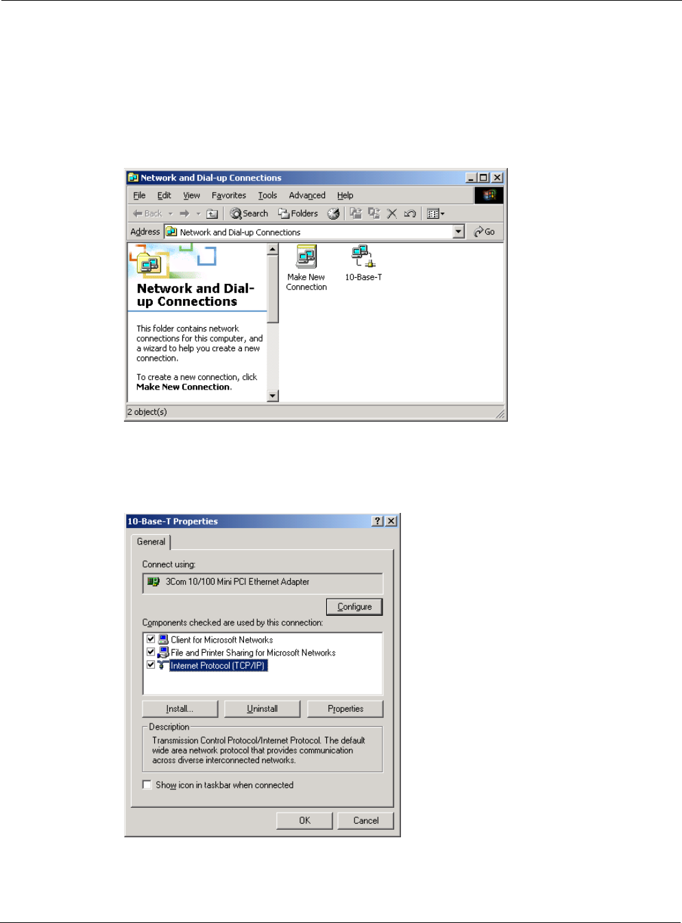
Preparing the Configuration Utility
Before you can access the Tropos Configuration Utility, you must set the IP address and subnet
mask on your computer, as described in the following steps:
1. From the Start button, select Setting > Network and Dial-Up Connections.
The Network and Dial-up Connections folder opens.
2. Right-click on the Ethernet interface for your PC (for example 10-Base-T).
3. Select Properties.
The Properties dialog box for your interface opens.
4. Select Internet Protocol (TCP/IP), and click Properties.
Chapter 4 Operating the Tropos 3210 Wi-Fi Cell
Tropos 3210 Wi-Fi Cell Hardware Installation Guide 21
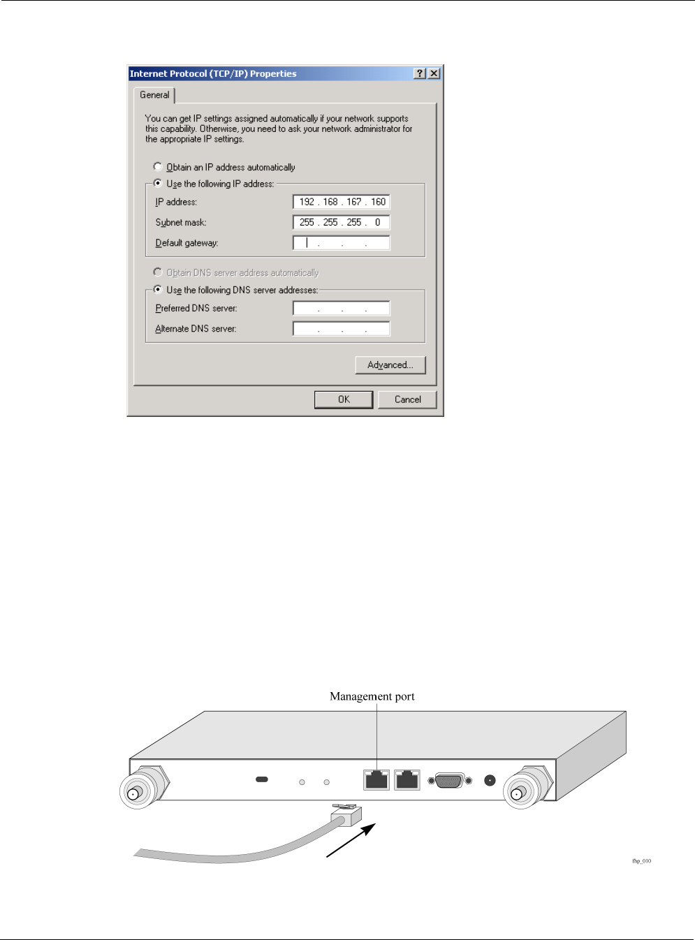
The Internet Protocol (TCP/IP) Properties dialog box opens.
5. Select Use the following IP address.
6. In the IP address box, enter 192.168.167.160
7. In the Subnet mask box, enter 255.255.255.0
8. Click OK.
9. Restart your computer.
Accessing the Configuration Utility
Follow these steps to access the Configuration Utility:
1. Connect your computer to the port marked Management on the Tropos 3210 Wi-Fi cell
using an IEEE 802.3 RJ-45 crossover cable.
Chapter 4 Operating the Tropos 3210 Wi-Fi Cell
Tropos 3210 Wi-Fi Cell Hardware Installation Guide 22
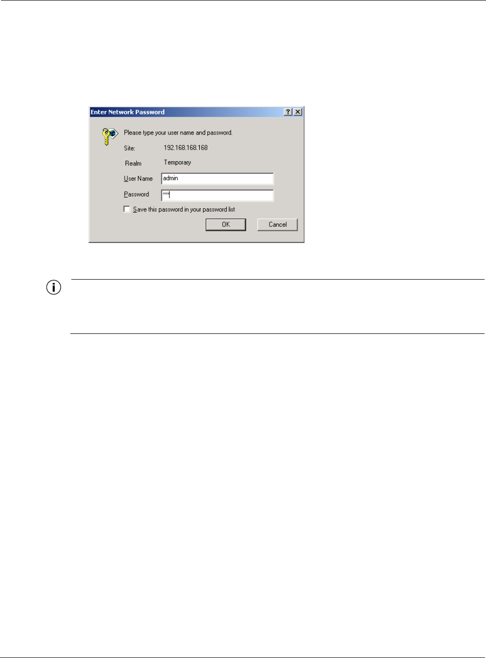
2. Start a Web browser (Explorer or Netscape) on your PC.
3. In the URL window of the browser, enter the management IP address of the Tropos 3210
Wi-Fi cell: https://192.168.167.166
4. When the Enter Network Password dialog box appears, enter the username admin and
password tropos, then click OK.
5. Once properly logged in, the Tropos Wireless Configuration Center screen opens.
Note
The first time you log in, you will be prompted to change the wireless routing domain ID. All
cells located within the same network must be assigned the same wireless routing domain
ID to communicate.
You have now successfully installed your Tropos 3210 Wi-Fi cell. To configure your wireless
gateway, refer to the Tropos Networks Configuration Guide.
Safety Information for the Tropos 3210 Wi-Fi Cell
The Federal Communications Commission (FCC) with its action in ET Docket 96-8 has adopted
a safety standard for human exposure to RF electromagnetic energy emitted by FCC certified
equipment. The Tropos 3210 series products meet the uncontrolled environmental limits found
in OET-65 and ANSI C95.1, 1991. Proper operation of this radio according to the instructions
found in this manual and the hardware and software guides on the Tropos 3210 Wi-Fi cell result
in user exposure that is substantially below the FCC recommended limits.
Guidelines to insure safe operation of the Tropos 3210 Wi-Fi cell
Do not touch or move the antenna(s) while the unit is transmitting or receiving.
Do not hold any component containing a radio such that the antenna is very close to or
touching any exposed parts of the body, especially the face or eyes, while transmitting.
Do not operate the radio or attempt to transmit data unless the antenna is connected;
otherwise, the radio may be damaged.

Chapter 4 Operating the Tropos 3210 Wi-Fi Cell
Tropos 3210 Wi-Fi Cell Hardware Installation Guide 23
Use in specific environments
Do not operate a portable transmitter near unshielded blasting caps or in an explosive
environment unless it is a type especially qualified for such use.
The use of wireless devices in hazardous locations is limited to the constraints posed by the
safety directors of such environments.
The use of wireless devices on airplanes is governed by the Federal Aviation Administration
(FAA).
The use of wireless devices in hospitals is restricted to the limits set forth by each hospital.
Antenna use guidelines
To comply with FCC RF exposure limits, dipole antennas should be located at a
minimum distance of 7.9 inches (20 cm) or more from the body of all persons.
High-gain, wall-mount or mast-mount antennas are designed to be professionally
installed and should be located at a minimum distance of 12 inches (30 cm) or more from
the body of all persons. Please contact your professional installer, VAR, or antenna
manufacturer for proper installation requirements.
Service Instructions
This section contains service information for the Tropos 3210 Wi-Fi cell.
Note
The Tropos 3210 Wi-Fi cell is not configured with user serviceable parts. The following
information is intended for trained service personnel only.
The Tropos 3210 Wi-Fi cells have a real-time clock which is powered by a small lithium
rechargeable battery. If real-time clock should fail, return the unit to Tropos Networks for
servicing.
Warning
There is a danger of explosion if the battery is incorrectly replaced. Replace the battery with
only the same or equivalent type recommended by the manufacturer. Dispose of used
batteries according to the manufacturer’s instructions.