ABB Enterprise Software 4902 4.9 GHz PCI Module User Manual 4310XA 4319XA Install Guide
Tropos Networks, Inc. 4.9 GHz PCI Module 4310XA 4319XA Install Guide
Users Manual
Tropos® Networks Mesh Router
Installation Guide
Models 4310-XA and 4319-XA
Part No. 200483-00 Rev A0
2013_03_21
ABB
555 Del Rey Ave.
Sunnyvale, CA 94085 USA
www.abb.com/tropos
408-331-6800

Tropos Mobile Mesh Router Installation Guide Models 4310-XA and 4319-XA 2
Copyright Notice
©2003-2013 Tropos Networks, Inc. All rights reserved. Tropos, Tropos Networks, PWRP, MetroMesh, and GridCom
are registered trademarks of Tropos Networks, Inc. All other brand names, company names, product names,
trademarks, and registered trademarks are the property of their respective holder(s). Information contained herein is
subject to change without notice. The only warranties for Tropos products and services are set forth in the express
warranty statements accompanying such products and services. Nothing herein should be construed as constituting an
additional warranty. Tropos shall not be liable for technical or editorial errors or omissions contained herein.
This product includes technology protected by U.S. Patents 6,704,301; 6,965,575; 7,016,328; 7,031,293; 7,058,021;
7,362,737; 7,376,087; 7,382,778; 7,397,789; 7,450,552; 7,460,489; 7,489,932; 7,499,409; 7,505,426; 7,542,421;
7,551,562; 7,564,781; 7,564,862; 7,580,393, 7,580,705; 7,586,879; 7,649,866; 7,668,137; 7,688,808; 7,689,224;
7,697,504; 7,706,285; 7,720,499; 7,729,278; 7,769,040; 7,843,891; 7,924,749; 7,929,975; 7,957,337; 7,970,394;
7,983,225; 8,031,615; 8,036,130; 8,036,186; 8,054,784; 8,055,759; 8,064,404
FCC Notice to Users and Operators
This equipment has been tested and found to comply with the limits for a Class B digital device,
pursuant to Part 15 of the FCC Rules. These limits are designed to provide reasonable protection
against harmful interference when the equipment is operated in a commercial environment. This
equipment generates, uses, and can radiate radio frequency energy and, if not installed and used
in accordance with the instruction manual, may cause harmful interference to radio
communications. Operation of this equipment in a residential area is likely to cause harmful
interference, in which case the user will be required to correct the interference at his own
expense. If this equipment does cause interference to radio or television reception, which can be
determined by turning the equipment off and on, the user is encouraged to correct the
interference by using one of the following measures:
Reorient or relocate the receiving antenna.
Increase separation between the equipment and receiver.
Connect the equipment to an outlet on a circuit different from that to which the receiver is
connected.
Consult the dealer or an experienced radio/TV technician.
This Part 15 radio device operates on a non-interference basis with other devices operating at
this frequency. Any changes or modification to said product not expressly approved by Tropos
Networks could void the user's authority to operate this device.
FCC Part 90Y Notice for 4.9 GHz Operation
Operation in the 4.9 GHz band requires an FCC license. The following eligibility rules are
specified in Part 90.1203 of the FCC rules:
Entities providing public safety services as defined under section 90.523 are eligible to hold
an FCC license for systems operating in the 4940-4990 MHz band. All of the requirements
and conditions set forth in that section also govern authorizations in the 4940-4990 MHz
band.
4.9 GHz band licensees may enter into sharing agreements or other arrangements for use of
the spectrum with entities that do not meet these eligibility requirements. However, all
applications in the band are limited to operations in support of public safety.

Tropos Mobile Mesh Router Installation Guide Models 4310-XA and 4319-XA 3
Contents
1 Installing the Tropos Mobile Mesh Router . . . . . . . . . . . . . . . . . . . . . . . . . 4
Introduction . . . . . . . . . . . . . . . . . . . . . . . . . . . . . . . . . . . . . . . . . . . . 4
Tropos 4310-XA Router . . . . . . . . . . . . . . . . . . . . . . . . . . . . . . . . . 4
Tropos 4319-XA Router — Public Safety . . . . . . . . . . . . . . . . . . . . 5
Preparing for Installation . . . . . . . . . . . . . . . . . . . . . . . . . . . . . . . . . . 6
Installation Accessories . . . . . . . . . . . . . . . . . . . . . . . . . . . . . . . . . 6
Selecting Router Locations . . . . . . . . . . . . . . . . . . . . . . . . . . . . . . . 6
Antenna Options . . . . . . . . . . . . . . . . . . . . . . . . . . . . . . . . . . . . . . . 7
Selecting Antenna Locations . . . . . . . . . . . . . . . . . . . . . . . . . . . . . 7
Cable Connections and Power . . . . . . . . . . . . . . . . . . . . . . . . . . . . 7
Install the Router . . . . . . . . . . . . . . . . . . . . . . . . . . . . . . . . . . . . . . . . 9
Mount the Router . . . . . . . . . . . . . . . . . . . . . . . . . . . . . . . . . . . . . . 9
Connect Power . . . . . . . . . . . . . . . . . . . . . . . . . . . . . . . . . . . . . . . . 9
Connect the CPE . . . . . . . . . . . . . . . . . . . . . . . . . . . . . . . . . . . . . 11
Connect the Antenna . . . . . . . . . . . . . . . . . . . . . . . . . . . . . . . . . . 11
Front Panel LED . . . . . . . . . . . . . . . . . . . . . . . . . . . . . . . . . . . . . . . 12
Service Instructions . . . . . . . . . . . . . . . . . . . . . . . . . . . . . . . . . . . . . 12
2 Product Specifications . . . . . . . . . . . . . . . . . . . . . . . . . . . . . . . . . . . . . . . . 13
3 Approved Antenna Configurations and Attenuation Settings . . . . . . . . 16
2.4 GHz Antenna . . . . . . . . . . . . . . . . . . . . . . . . . . . . . . . . . . . . . . . 16
4.9 GHz Antenna . . . . . . . . . . . . . . . . . . . . . . . . . . . . . . . . . . . . . . . 17
4 Ordering Information . . . . . . . . . . . . . . . . . . . . . . . . . . . . . . . . . . . . . . . . . . 19

Tropos Mobile Mesh Router Installation Guide Models 4310-XA and 4319-XA 4
1Installing the Tropos Mobile Mesh
Router
This guide explains how to install the Tropos Mobile Mesh Router, Models 4310-XA-and 4319-
XA. This chapter contains the following sections:
Preparing for Installation
Mount the Router
Front Panel LED
Service Instructions
Service Instructions
Introduction
The Tropos 4310-XA and 4319-XA Mobile Mesh Routers are designed to provide mobile mesh
router functionality in extremely harsh environments. They are IP-67 rated for outdoor
installation and offer greater shock and vibration resistance than the standard Tropos Mobile
Mesh Routers, the Tropos 4310 and Tropos 4319.
This document contains installation instructions for the following products:
Tropos 4310-XA Router
Tropos 4319-XA Router — Public Safety
Tropos 4310-XA Router
The Tropos 4310-XA router for the FCC regulatory domain has the following characteristics:
802.11b/g/n 2400-2483 MHz
DC power, 11-55 VDC
CPE 10/100BaseT Ethernet ports
Table 1 lists the Tropos 4310-XA router model.
Table 1 Tropos 4310-XA Router Models—FCC
Model Description
43103000X 4310-XA: Mobile router, 2.4 GHz, DC power

Chapter 1
Tropos Mobile Mesh Router Installation Guide Models 4310-XA and 4319-XA 5
Tropos 4319-XA Router — Public Safety
The Tropos 4319-XA router for licensed FCC public safety applications has the following
characteristics:
802.11a, 4940-4990 MHz
DC power, 11-55 VDC
CPE 10/100BaseT Ethernet port
Note
Operation in the 4.9 GHz band requires an FCC license. The following eligibility rules are specified in Part
90.1203 of the FCC rules:
• Entities providing public safety services as defined under section 90.523 are eligible to hold an FCC
license for systems operating in the 4940-4990 MHz band. All of the requirements and conditions set
forth in that section also govern authorizations in the 4940-4990 MHz band.
• 4.9 GHz band licensees may enter into sharing agreements or other arrangements for use of the
spectrum with entities that do not meet these eligibility requirements. However, all applications in the
band are limited to operations in support of public safety.
Table 2 lists the Tropos 4319-XA router model for public safety applications.
Table 2 Tropos 4319-XA Routers—Public Safety
Model Description
43193010X 4.9 GHz, DC power
Chapter 1
Tropos Mobile Mesh Router Installation Guide Models 4310-XA and 4319-XA 6
Preparing for Installation
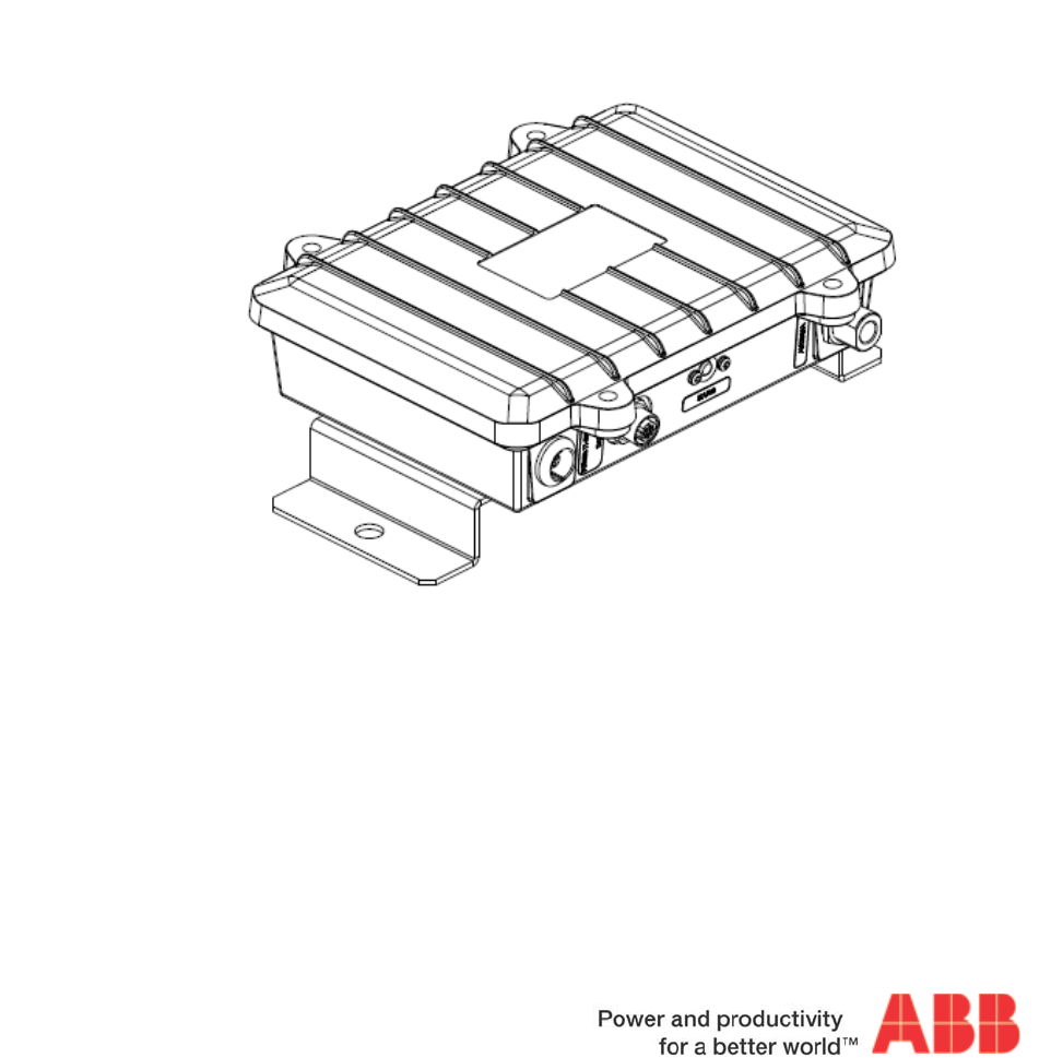
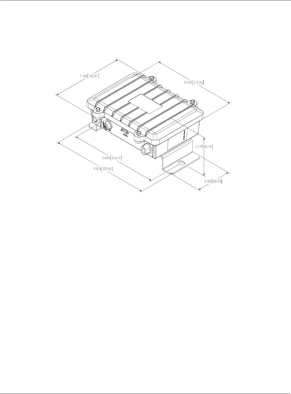
Figure 1 shows the mobile router unit and dimensions.
FIGURE 1 Tropos Mobile Router
Installation Accessories
You must supply the following accessories:
Hardware to mount the router
Ethernet cable with M-12 connector to connect the router to the client device
Power cable with LEMO connector
Antennas and antenna cables
Selecting Router Locations
Tropos routers are radio devices, and as such, they are susceptible to common causes of
interference that can reduce throughput and range. Follow these general guidelines when
selecting an installation location:
Install the router away from other possible sources of WLAN interference at 2.4 GHz or 4.9
GHz.
Choose a mounting surface that is at least 13.25 inches by 8 inches to provide sufficient
space to screw the router into the surface (Figure 1). It is not necessary to level the router.

Chapter 1
Tropos Mobile Mesh Router Installation Guide Models 4310-XA and 4319-XA 7
Note
The router contains integral ESD protection and vehicle power conditioning, so external protection is not
required.
Antenna Options
You can purchase any of the Tropos-approved, cable-attached antennas that are listed in
“Ordering Information” on page 19 (see Figure 6 on page 19). Omni-directional antennas are
best for systems requiring a signal distribution in more than one direction.
Caution
To comply with regulatory RF exposure limits, locate antennas a minimum distance of 7.9 inches (20cm)
from people.
Note
Only use antennas that are approved by Tropos. Operating the unit with non-qualified antennas is a
violation of U.S. FCC Rules Part 15.203(c), Code of Federal Regulations, Title 47.
Selecting Antenna Locations
The Tropos 4310-XA and 4319-XA Mobile Mesh Routers can be mounted on the outside of a
vehicle with an antenna connected directly to the router or they can be mounted inside the
vehicle with an antenna mounted outside the vehicle.
If possible, the router should be mounted outside the vehicle as this eliminates the need for the
use of coaxial cable between the router and antenna. Use of coaxial cable introduces losses in the
system which reduces the effective transmit power.
If an omnidirectional antenna is used, it should be mounted vertically. If the router is mounted
externally and is situated so that its antenna connector is on the side, a right-angle N-connector
should be used in order to get the antenna in a vertical orientation.
Tropos recommends the use of low loss coaxial cable such as LMR-240 or LMR-400 for
connecting the router to an external antenna.
Follow these guidelines during installation:
Install the antenna on the highest part of the vehicle so that it is clear of obstructions within
at least a 3ft radius. Other antennas do not need to be considered as sources of obstruction.
Install the antenna on the flattest area of the roof.
Keep the antenna cable as short as possible.
Chapter 1
Tropos Mobile Mesh Router Installation Guide Models 4310-XA and 4319-XA 8
Cable Connections and Power
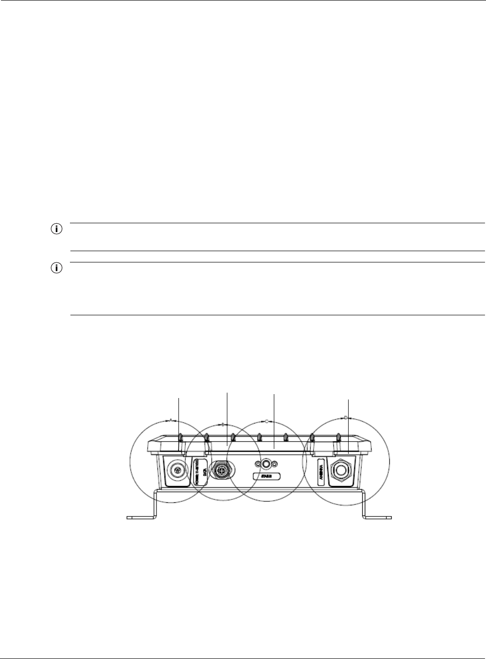
Figure 2 shows the power and connector ports on the side panel of the mobile outer:
The status indicator is red when the router is not connected to the Tropos network. It is green
when the router has a working IP address and network connectivity.
The CPE port is used to connect the router to a computer or other client device.
Figure 2 shows the connectors and indicators on the mobile router, from left to right they are:
Power: LEMO size 1k/1 circular push pull fixed receptacle, 3-pole female
CPE Ethernet: 4-pole, circular M-12 D-coded female
Status LED
Antenna: N-type, male
The router is designed to be used with negative ground systems, such as motor vehicle power.
There is no internal battery back-up, so the vehicle must be powered for the router to operate.
Note
The router requires quality shielded CAT5 Ethernet data cables.
Note
The router does not have a power switch. It is powered when the power plug is attached and then
connected to vehicle power. To remove power from an installed router, remove the power plug, remove the
fuse, or turn off vehicle power.
FIGURE 2 Connector Panel
CPE Ethernet Status LED
Power Antenna
Chapter 1
Tropos Mobile Mesh Router Installation Guide Models 4310-XA and 4319-XA 9
Install the Router
Perform these tasks to install the router:
1. Mount the Router
2. Connect Power
3. Connect the CPE
4. Connect the Antenna
Mount the Router
The Tropos 4310-XA and 4319-XA routers have a metal mounting bracket attached for
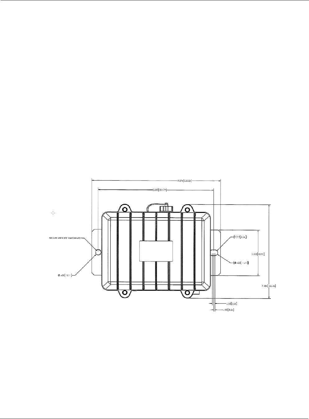
mounting the router to most types of surfaces. As shown in Figure 3, the mounting bracket has
two holes for fasteners. These holes are 8.85" (224.79mm) apart on centers.
Use 3/8" or 10mm fasteners appropriate to the material on which the router is being mounted.
FIGURE 3 Router Mounting
Chapter 1
Tropos Mobile Mesh Router Installation Guide Models 4310-XA and 4319-XA 10
Connect Power
Connect 11-55VDC to the POWER connector. The Tropos 4310-XA and 4319-XA use the
following connector for DC power:
LEMO size 1k/1 circular push pull fixed receptacle, 3-pole female (LEMO part number
EGG.1k.303.CLL)
The installer is responsible for providing the power cable that connects to the router's power
receptacle. The correct LEMO part for the mating connector is:
FGG.1k.303.CLA
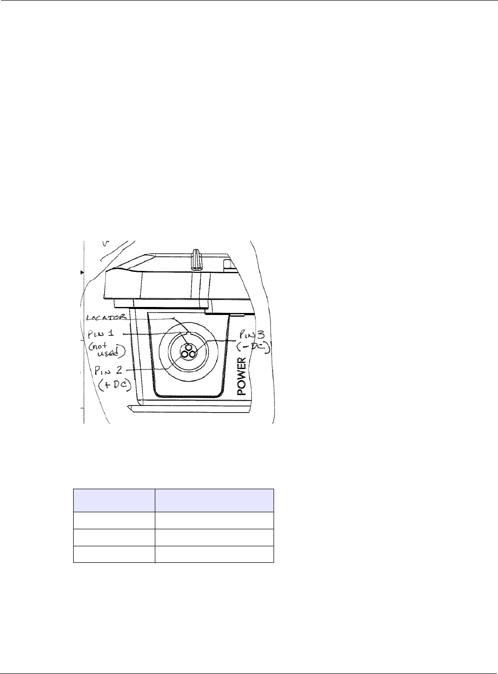
Figure 4 and Table 3 show the pin assignments for the DC power connector.
<<Updated figure needed>>
FIGURE 4 Pin Assignments for the DC Power Connector
TABLE 3 Pin Assignments
Pin Function
1 No connection
2 DC +
3 DC -
Chapter 1
Tropos Mobile Mesh Router Installation Guide Models 4310-XA and 4319-XA 11
Connect the CPE
Connect the Ethernet CPE to the DATA connector:
4-pole, circular M-12 D-coded female
The installer is responsible for providing the Ethernet cable and connector.
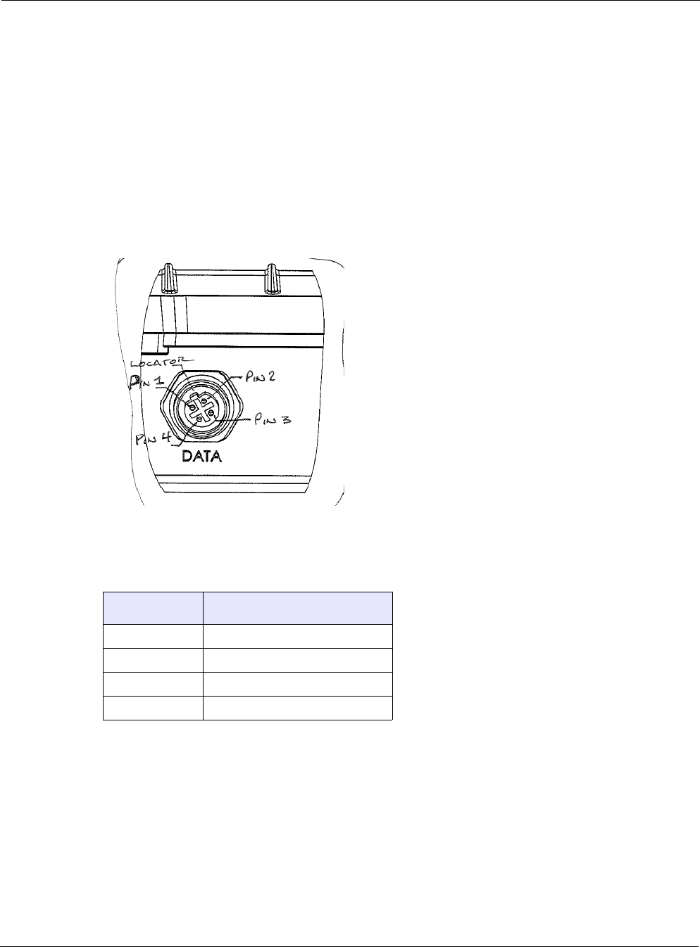
Figure 5 and Table 4 show the wiring for the DATA connector.
<<Updated figure needed>>
FIGURE 5 Pin Assignments for the DC Power Connector
Connect the Antenna
Connect the antenna to the N-type connector on the router. Either connect an antenna directly to
the N-connector (requires that the router be mounted outside of the vehicle) or use low-loss
coaxial cable to connect the router to an antenna mounted outside of the vehicle. Always use the
shortest length of cable possible. Always mount the antenna in a vertical orientation.
TABLE 4 Pin Assignments for CPE
Pin Function
1TX Data +
2RX Data +
3TX Data -
4RX Data -

Chapter 1
Tropos Mobile Mesh Router Installation Guide Models 4310-XA and 4319-XA 12
Front Panel LED
Table 5 lists the front panel LED states. Pin 9 is used for the Remote Indicator (“Service
Instructions” on page 12).
Service Instructions
There are no user-servicable items in the router.
Table 5 LED States
LED Color Network State
Red Not connected
Green Connected

Tropos Mobile Mesh Router Installation Guide Models 4310-XA and 4319-XA 13
2Product Specifications
This chapter contains the product specifications for the Tropos 4310-XA and 4319-XA mobile
routers:
Physical Specifications
Interfaces
Power Options
Certifications
Table 6 Physical Specifications
Specification Value
Physical Dimensions (with mounting brackets)
Inches Height: 3.2
Width: 9.9
Depth: 7.2
Centimeters Height: 8.1
Width: 25.0
Depth: 18.25
Weight
lbs - maximum 3.0 (includes all brackets)
Kg - maximum 1.3
Temperature Min
Operating Range Min: -40o C
Max: 70o C
Storage Range Min: -40o C
Max: 85o C
Shock and Vibration
Operational: MIL-STO-202E
ETSI 30-19-2-4
T41.E Class 4M3
Transportation: ISTA 2A
Chapter 2
Tropos Mobile Mesh Router Installation Guide Models 4310-XA and 4319-XA 14
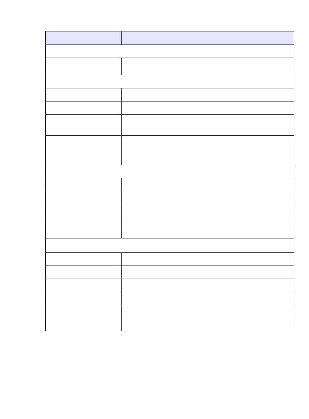
Table 7 Interfaces
Specification Value
CPE Data Interface
IEEE 802.3 10/100BaseT • Auto sensing
• 4-pole, circular M-12, D-coded female connector
802.11b/g/n Wireless Interface
Standard IEEE 802.11b/g/n Wi-Fi
Frequency Range 2400 to 2483 MHz ISM Band (CH 1-11) FCC Part 15
Modulation 802.11 g/n - OFDM (64-QAM, 16-QAm, QPSK, BPSK)
802.11 b
Rx Sensitivity -100dBm (1 Mbps)
-94dBm (6 Mbps)
--76dBm (54 Mbps)
802.11a Wireless Interface
Standard IEEE 802.11a Wi-Fi
Frequency Range 4940 - 4990 MHz Public Safety (FCC Part 90)
Modulation OFDM (64-QAH, 16-QAM)
Rx Sensitivity -94dBm (6 Mbps)
-76dBm (54 Mbps)
RF Interface
Antennas External
Lightning Protection <= 0.5μJ for 3kA @ 8/20μS Waveform
Impedance 50 ohms
VSWR 1.5 : 1
Connector N (female)
Indicator - Status Lamp Red/Green

Chapter 2
Tropos Mobile Mesh Router Installation Guide Models 4310-XA and 4319-XA 15
Table 8 Power Options
Specification Value
DC 11-55 VDC
8W typical
Polarity protected
ESD Protection EN61000-4-2 Level 2 ESD Immunity
EN61000-4-5 Level 4 Surge Immunity
Fuse Automotive mini-blade 32 VDC 7.5A
Table 9 Certifications
Certifications
CFR 47 FCC Part 15; Class B (4310-XA)
Industry Canada RSS210 (4310-XA)
UL 60950-1
EN 60950
IEC 950
FCC CFR 47 Part 90 (4310-XA)
Tropos Mobile Mesh Router Installation Guide Models 4310-XA and 4319-XA 16
3Approved Antenna Configurations and
Attenuation Settings
This chapter lists approved antenna configurations and attenuation settings:
“2.4 GHz Antenna” on page 16
“4.9 GHz Antenna” on page 17
2.4 GHz Antenna
The information in this section applies to the Tropos 4310-XA mobile.
Table 10 lists antenna configurations.
Note
CANADA ONLY: This device has been designed to operate with the antennas listed in Table 10, and
having a maximum gain of 12dBi. Antennas not included in this list or having a gain greater than 12dBi are
strictly prohibited for use with this device. The required antenna impedance is 50 ohms.
Note
To reduce potential radio interference to other users, the antenna type and its gain should be so chosen
that the Effective Isotropic Radiated Power (EIRP) is not more than that permitted for successful
communication.
Table 10 802.11b/g Antenna Configurations (2400-2483 MHz)
Antenna Ordering
Number
Measured
Cond. Avg.
Power (dBm)
Tx
Attenuation
Software
Setting (dB) Approximate
EIRP (dBm)
7.4dBi omni, unit mounted (with cable)
7.4dBi omni, unit mounted (without
cable)
7.4dBi omni, unit mounted (MAG-
mount)
AN074090
AN074091
AN074095
28.6 0 36

Chapter 3
Tropos Mobile Mesh Router Installation Guide Models 4310-XA and 4319-XA 17
Attenuation with External Antennas
If external antennas are used, it is necessary to adjust the transmit power attenuation to provide
the correct power level for the router. Use the following formulas to compute the required
attenuation level:
Gain’ (dBi) = Antenna Gain (dBi) - Cable Loss (dB)
802.11b/g:
4.9 GHz Antenna
The information in this section applies to the Tropos 4319-XA router.
Note
Operation in the 4.9 GHz band requires an FCC license. The following eligibility rules are specified in Part
90.1203 of the FCC rules:
• Entities providing public safety services as defined under section 90.523 are eligible to hold an FCC
license for systems operating in the 4940-4990 MHz band. All of the requirements and conditions set
forth in that section also govern authorizations in the 4940-4990 MHz band.
• 4.9 GHz band licensees may enter into sharing agreements or other arrangements for use of the
spectrum with entities that do not meet these eligibility requirements. However, all applications in the
band are limited to operations in support of public safety.
Note
To reduce potential radio interference to other users, the antenna type and its gain should be so chosen
that the Effective Isotropic Radiated Power (EIRP) is not more than that permitted for successful
communication.
Tx Antenna Setting (dB) = 0
Gain’ - 7
if Gain’ < 7 dBi
if Gain’ > 7dBi
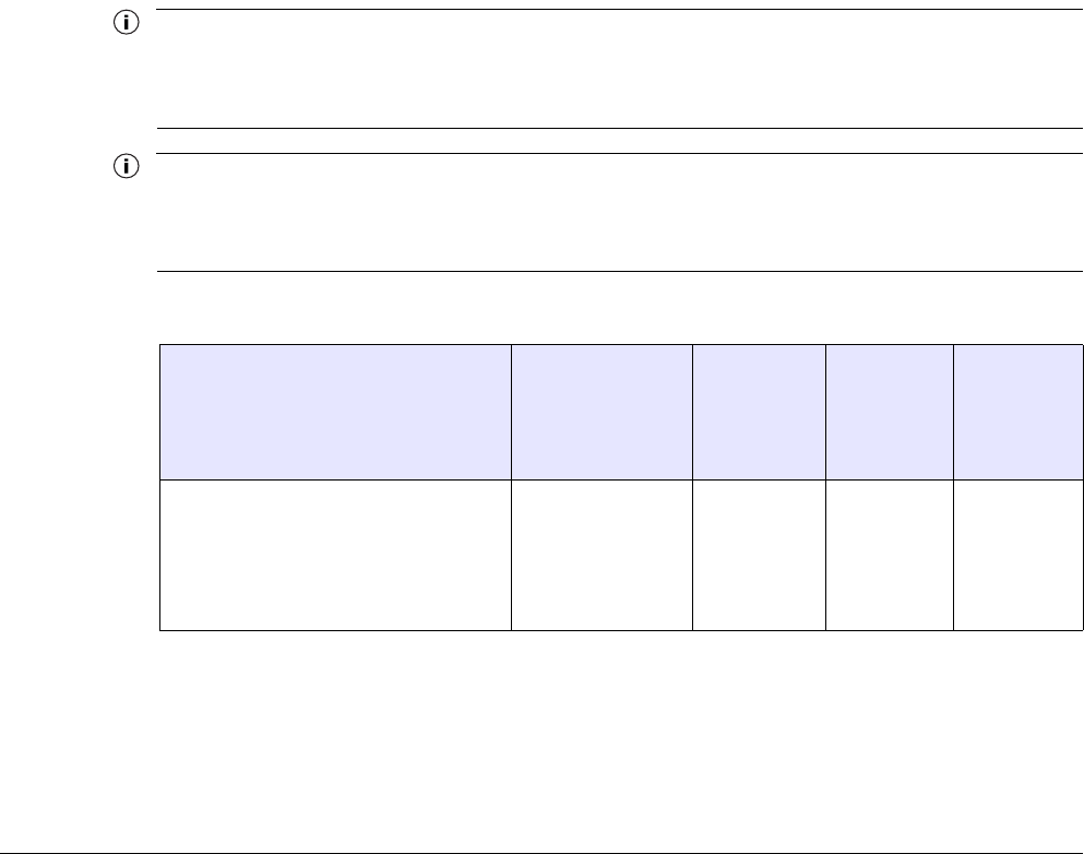
Table 11 802.11a Antenna Configurations for Public Safety (4940-4990 MHz)
Antenna Ordering
Number
Channel
Bandwidth /
Operating
Frequency (MHz)
Measured
Conducted
Power (dBm)
Tx
Attenuation
Software
Setting (dB) Approximate
EIRP (dBm)
9.0dBi omni, magnetic
mount
AN090049 20
4950 - 4980
20.0 4 29.0

Chapter 3
Tropos Mobile Mesh Router Installation Guide Models 4310-XA and 4319-XA 18
Attenuation with External Antennas
If external antennas are used, it is necessary to adjust the transmit power attenuation to provide
the correct power level for the router. Use the following formulas to compute the required
attenuation level:
Gain’ (dBi) = Antenna Gain (dBi) - Cable Loss (dB)
802.11b/g:
802.11a:
Tx Antenna Setting (dB) = 0
Gain’ - 7
if Gain’ < 7 dBi
if Gain’ > 7dBi
Tx Antenna Setting (dB) = 4
Gain’ - 5
if Gain’ < 9 dBi
if Gain’ > 9 dBi

Tropos Mobile Mesh Router Installation Guide Models 4310-XA and 4319-XA 19
4Ordering Information
Table 6 contains ordering information for the Tropos mobile routers and related equipment.
These items can be ordered from Tropos Networks, Inc.
FIGURE 6 Tropos Ordering Information
Part No. Description
43103000X Tropos 4310-XA Mobile Mesh Router, variable power, N connectors
43193010X Tropos 4319-XA Mobile Mesh Router, variable power, N connectors
RC009100 Right angle N-connector adapter: male/female
AN074090 One vehicle mounted 7.4dBi omni antenna and cable kit, 2400-2500 MHz
AN074091 One vehicle magnetic mounted 7.4dBi omni antenna and cable kit, 2400-2500 MHz
AN074095 One vehicle mounted 7.4dBi omni antenna (cable kit not included), 2400-2500 MHz
AN090049 9.0dBi omni antenna, 4.9 GHz, magnetic mount, 10 foot cable, N-male