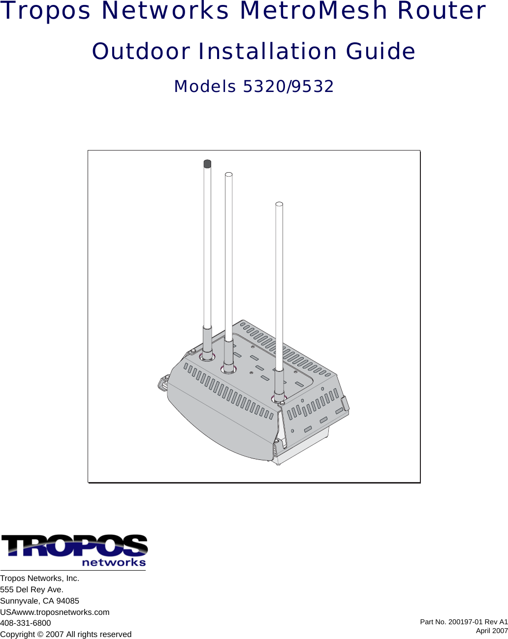
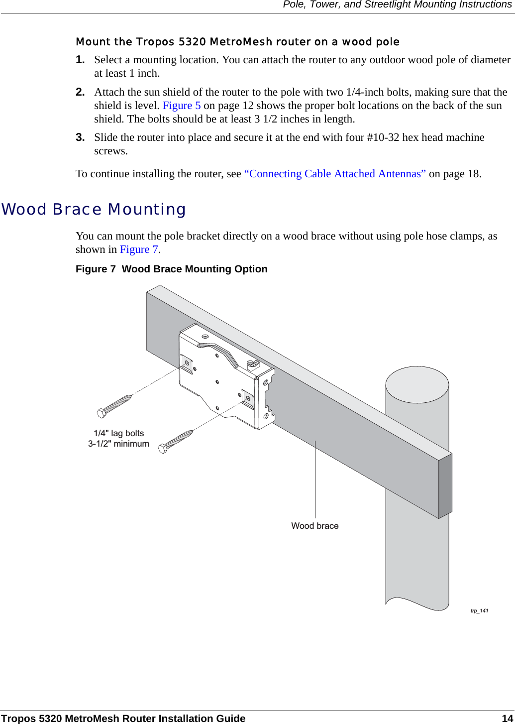
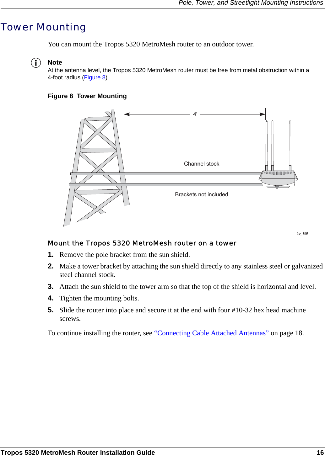
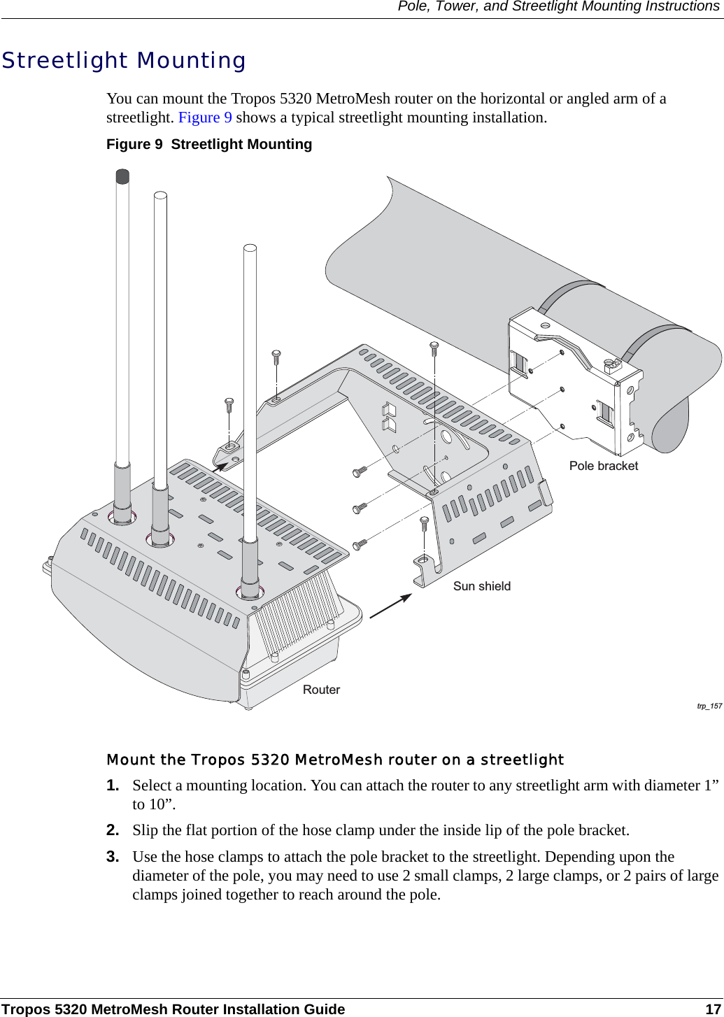
ABB Enterprise Software BF4P9 Wireless Router User Manual 5320 Guide

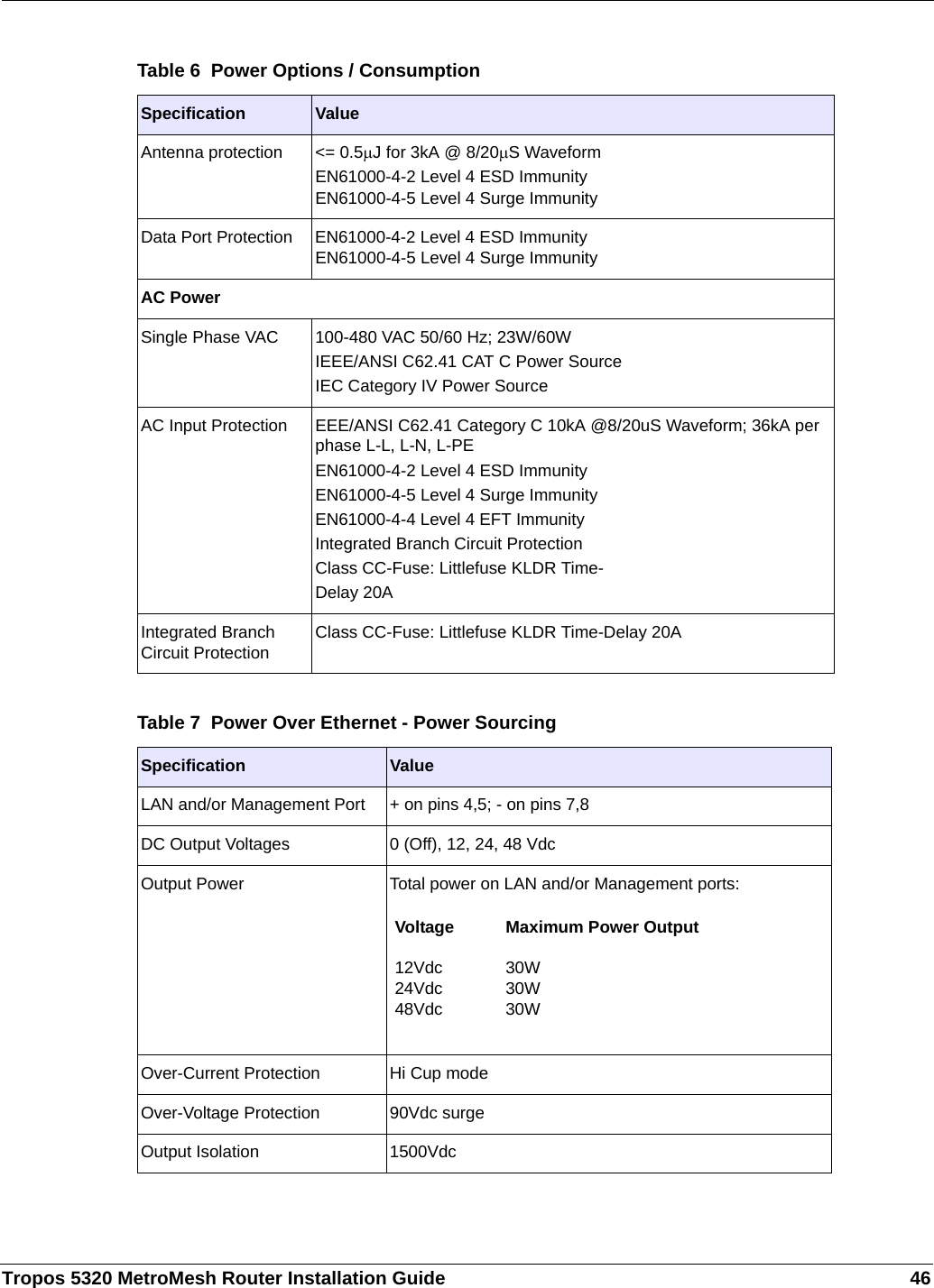
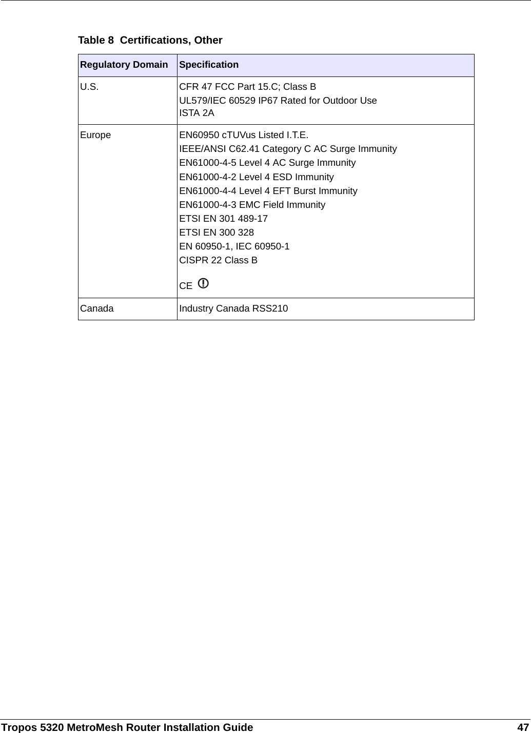
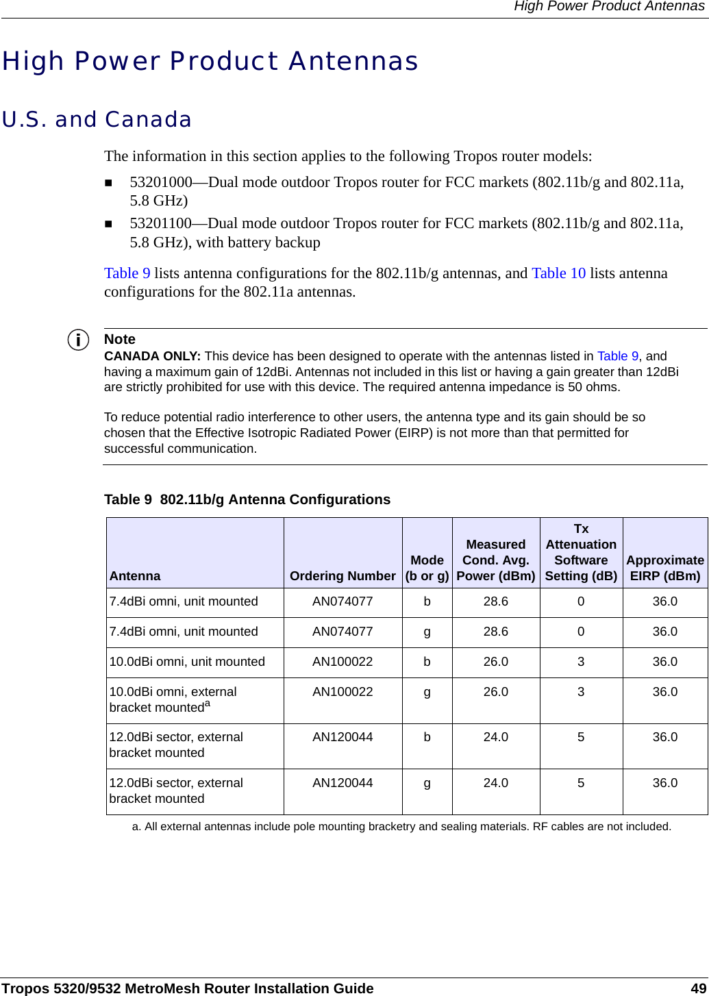
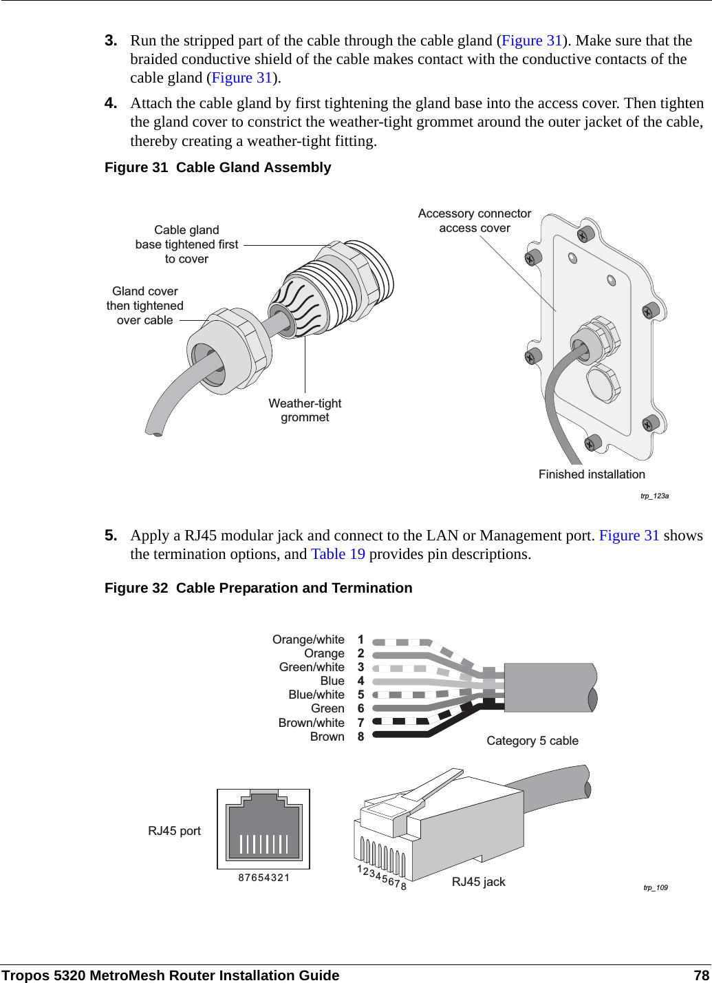
Tropos Networks, Inc. Wireless Router 5320 Guide

User Manual

Part No. 200197-01 Rev A1April 2007Tropos Networks MetroMesh RouterOutdoor Installation GuideModels 5320/9532Tropos Networks, Inc.555 Del Rey Ave.Sunnyvale, CA 94085USAwww.troposnetworks.com408-331-6800Copyright © 2007 All rights reserved
Tropos 5320 MetroMesh Router Installation Guide iiCopyright Notice©2007 Tropos Networks, Inc. All rights reserved. Tropos Networks is a registered trademark of Tropos Networks, Inc. in the United States and certain other jurisdictions. Specifications are subject to change without notice.Loctite is a registered trademark of Loctite Corporation, USA.This product includes technology protected by U.S. Patents 6,704,301; 6,965,575; 7,016,328; 7,031,293; and 7,058,021.FCC Notice to Users and OperatorsThis device complies with Part 15 of the FCC Rules. Operation is subject to the following two conditions: (1) this device may not cause harmful interference, and (2) this device must accept any interference received, including interference that may cause undesired operation.This equipment has been tested and found to comply with the limits for a Class B digital device, pursuant to Part 15 of the FCC Rules. These limits are designed to provide reasonable protection against harmful interference when the equipment is operated in a commercial environment. This equipment generates, uses, and can radiate radio frequency energy and, if not installed and used in accordance with the instruction manual, may cause harmful interference to radio communications. Operation of this equipment in a residential area is likely to cause harmful interference, in which case the user will be required to correct the interference at his own expense. If this equipment does cause interference to radio or television reception, which can be determined by turning the equipment off and on, the user is encouraged to correct the interference by using one of the following measures:Reorient or relocate the receiving antenna. Increase separation between the equipment and receiver. Connect the equipment to an outlet on a circuit different from that to which the receiver is connected. Consult the dealer or an experienced radio/TV technician.This Part 15 radio device operates on a non-interference basis with other devices operating at this frequency. Any changes or modification to said product not expressly approved by Tropos Networks could void the user's authority to operate this device.Industry CanadaNotice to users and operators:This Class B digital apparatus meets all requirements of the Canadian Interference Causing Equipment Regulations. Operation is subject to the following two conditions: (1) this device may not cause harmful interference, and (2) this device must accept any interference received, including interference that may cause undesired operation.
Tropos 5320 MetroMesh Router Installation Guide iiiCet appareillage numérique de la classe B répond à toutes les exigences de l’interférence canadienne causant des réglements d’équipement. L’opération est sujette aux deux conditions suivantes : (1) cet dispositif peut ne pas causer l'interférence nocive, et (2) ce dispositif doit accepter n’importe quelle interférence reçue, y compris l'interférence qui peut causer l’opération peu désirée.WarningIt is illegal to modify the construction of this product. Modifying the operating frequency or enhancing the transmit output power through the use of external amplifiers or other equipment is specifically disallowed by the “Telecommunications Act.”WarningThis device is for outdoor or indoor use with conditions that no harmful interference to authorized radio stations results from the operation of this device. This device shall not influence aircraft security and/or interfere with legal communications as defined in the “Telecommunications Act.” If this device is found to cause interference, the operator of this equipment shall cease operating this device immediately until no interference is achieved. European Union WEEE NoticeIt is important for users of this equipment to participate in reuse, recycling, and other forms of recovery. The potential effects on the environment and human health as a result of the presence of hazardous substances in electrical and electronic equipment are a waste of natural resources and cause pollution.For EU member countries, this symbol means: Do not dispose of this equipment as unsorted municipal waste. This equipment must be collected separately. The return and collection of this product has not been defined at this time, please contact Tropos Networks for return and/or collection.
Tropos 5320 MetroMesh Router Installation Guide ivEuropean Community Language Versions of Informal Statement for Inclusion in User Information The following statements are in accordance with Article 6.3 of Directive 1999/5/EC.53205320532053205320532053205320532053205320532053205320
Tropos 5320 MetroMesh Router Installation Guide vSTOP!! STOP!! STOP!! STOP!!READ THIS FIRST!Important Safety InstructionsThe exclamation point within an equilateral triangle is intended to alert the user to the presence of important operating and maintenance (servicing) instructions in the literature accompanying the product.The lightning flash with an arrowhead symbol within an equilateral triangle is intended to alert the user to the presence of uninsulated “dangerous voltage” within the product’s enclosure that may be of sufficient magnitude to constitute a risk of electric shock to persons.CautionRead these instructions.Keep these instructions.Heed all warnings.Follow all instructions. Do not defeat the safety purpose of the grounding.Only use attachments/accessories specified by the manufacturer.Refer all servicing to qualified service personnel. Servicing is required when the apparatus has been damage in any way, such as power-supply cord or plug is damaged, liquid has been spilled on objects have fallen into the apparatus, the apparatus has been exposed to rain or moisture, does not operate normally, or has been dropped.
Tropos 5320 MetroMesh Router Installation Guide viWarningRisk of personal injury or death when installing this device!There is a risk of personal injury or death if the router antennas come near electric power lines. Carefully read and follow all instructions in this manual. By nature of the installation, you may be exposed to hazardous environments and high voltage. Use caution when installing the outdoor system.This apparatus must be connected to earth ground. Do not open the unit — risk of electric shock inside.Risque d'électrocution. Ne pas ouvrir l'unité.CautionYou are cautioned that any change or modification not expressly approved in this manual could void your authority to operate this equipment.Les changements et modifications, non expressément approuvés dans le présent manuel, peuvent entraîner une interdiction d'utiliser cet appareil pour l'utilisateur.ServiceThere are no user-serviceable parts inside. All service must be performed by qualified personnel.Vous ne devez pas réparer les pièces se trouvant à l'intérieur de l'appareil. Les réparations doivent être effectuées uniquement par du personnel qualifié.The Tropos 5320 MetroMesh Router may contain a lithium-ion battery. To avoid the possibility of an explosion, the Tropos 5320 MetroMesh Router should NOT be exposed to any temperatures higher than 85 degrees C. The RJ45 connectors of your Tropos 5320 MetroMesh Router may source DC power on pins 4,5 and 7,8. The IEEE 802.3 standards allow for pins 4,5 and 7,8 to be used for Power Over Ethernet. Some products may be incompatible with the Tropos Power Over Ethernet capability. If such problems occur, make sure that the unit is configured with the Power Over Ethernet capability set to Off (default setting). If problems persist, use Ethernet cables that have no connections to the unused pins 4,5 and 7,8.
Tropos 5320 MetroMesh Router Installation Guide viiThe Tropos 5320 MetroMesh Router is installed in wet, outdoor locations. Make sure closure caps are installed and all cable connections are securely fastened and waterproofed.The Tropos 5320 MetroMesh Router can only be used with approved antennas. See Appendix C, “Approved Antenna Configurations and Attenuation Settings”  for further information.Surfaces may become hot. Use caution when accessing the Tropos 5320 MetroMesh router.
Tropos 5320 MetroMesh Router Installation Guide viiiContents1 Installing the Tropos MetroMesh Router   . . . . . . . . . . . . . . . . . . . . . . . . .  1Preparing for Installation  . . . . . . . . . . . . . . . . . . . . . . . . . . . . . . . . . . . . .  2Model Numbers   . . . . . . . . . . . . . . . . . . . . . . . . . . . . . . . . . . . . . . . . .  2Installation Hardware and Tools  . . . . . . . . . . . . . . . . . . . . . . . . . . . . .  4Site Planning . . . . . . . . . . . . . . . . . . . . . . . . . . . . . . . . . . . . . . . . . . . .  4Location Guidelines   . . . . . . . . . . . . . . . . . . . . . . . . . . . . . . . . . . . . . .  5Antenna Options . . . . . . . . . . . . . . . . . . . . . . . . . . . . . . . . . . . . . . . . .  5Site Surveys  . . . . . . . . . . . . . . . . . . . . . . . . . . . . . . . . . . . . . . . . . . . .  5Power Source  . . . . . . . . . . . . . . . . . . . . . . . . . . . . . . . . . . . . . . . . . . .  6Safety  . . . . . . . . . . . . . . . . . . . . . . . . . . . . . . . . . . . . . . . . . . . . . . . . .  6Mounting Strategies . . . . . . . . . . . . . . . . . . . . . . . . . . . . . . . . . . . . . . . . .  7Proper Use of Hose Clamps. . . . . . . . . . . . . . . . . . . . . . . . . . . . . . . . . . .  8Pole, Tower, and Streetlight Mounting Instructions . . . . . . . . . . . . . . . . .  9Metal Pole Mounting . . . . . . . . . . . . . . . . . . . . . . . . . . . . . . . . . . . . .  10Wood Pole Mounting   . . . . . . . . . . . . . . . . . . . . . . . . . . . . . . . . . . . .  13Wood Brace Mounting   . . . . . . . . . . . . . . . . . . . . . . . . . . . . . . . . . . .  14Tower Mounting  . . . . . . . . . . . . . . . . . . . . . . . . . . . . . . . . . . . . . . . .  16Streetlight Mounting  . . . . . . . . . . . . . . . . . . . . . . . . . . . . . . . . . . . . .  17Connecting Cable Attached Antennas . . . . . . . . . . . . . . . . . . . . . . . . . .  18Waterproofing Antenna Connections  . . . . . . . . . . . . . . . . . . . . . . . .  20Installing Attached Antennas   . . . . . . . . . . . . . . . . . . . . . . . . . . . . . .  21Grounding the Tropos 5320 Router . . . . . . . . . . . . . . . . . . . . . . . . . . . .  21Grounding the Data Protection Device  . . . . . . . . . . . . . . . . . . . . . . .  23Connecting Power  . . . . . . . . . . . . . . . . . . . . . . . . . . . . . . . . . . . . . . . . .  24Categories of Power  . . . . . . . . . . . . . . . . . . . . . . . . . . . . . . . . . . . . .  24Connecting to AC Power (Category C) . . . . . . . . . . . . . . . . . . . . . . .  27Connecting to Streetlight Power (Category C)  . . . . . . . . . . . . . . . . .  28Connecting a Data Port . . . . . . . . . . . . . . . . . . . . . . . . . . . . . . . . . . . . .  30Resetting the Router  . . . . . . . . . . . . . . . . . . . . . . . . . . . . . . . . . . . . . . .  34Connecting Peripherals . . . . . . . . . . . . . . . . . . . . . . . . . . . . . . . . . . . . .  35Battery Backup Operation  . . . . . . . . . . . . . . . . . . . . . . . . . . . . . . . . . . .  37Safety Information for the Tropos MetroMesh Router . . . . . . . . . . . . . .  37
Tropos 5320 MetroMesh Router Installation Guide ix2 Power Consumption  . . . . . . . . . . . . . . . . . . . . . . . . . . . . . . . . . . . . . . . . .  393 Product Specifications  . . . . . . . . . . . . . . . . . . . . . . . . . . . . . . . . . . . . . . .  414 Approved Antenna Configurations and Attenuation Settings  . . . . . . .  48High Power Product Antennas . . . . . . . . . . . . . . . . . . . . . . . . . . . . . . . .  49U.S. and Canada   . . . . . . . . . . . . . . . . . . . . . . . . . . . . . . . . . . . . . . .  49Standard Power Product Antennas . . . . . . . . . . . . . . . . . . . . . . . . . . . .  51Europe   . . . . . . . . . . . . . . . . . . . . . . . . . . . . . . . . . . . . . . . . . . . . . . .  51Public Safety Product Antennas. . . . . . . . . . . . . . . . . . . . . . . . . . . . . . .  53U.S. and Canada   . . . . . . . . . . . . . . . . . . . . . . . . . . . . . . . . . . . . . . .  535 Antenna Specifications and Patterns  . . . . . . . . . . . . . . . . . . . . . . . . . . .  556 Installation Accessories . . . . . . . . . . . . . . . . . . . . . . . . . . . . . . . . . . . . . .  657 AC Wiring Diagrams  . . . . . . . . . . . . . . . . . . . . . . . . . . . . . . . . . . . . . . . . .  688 Wind Loading Considerations  . . . . . . . . . . . . . . . . . . . . . . . . . . . . . . . . .  719 Canopy Installation Instructions  . . . . . . . . . . . . . . . . . . . . . . . . . . . . . . .  7210 Cable Termination Instructions  . . . . . . . . . . . . . . . . . . . . . . . . . . . . . . . .  77Abbreviations   . . . . . . . . . . . . . . . . . . . . . . . . . . . . . . . . . . . . . . . . . . . . . .  80Index . . . . . . . . . . . . . . . . . . . . . . . . . . . . . . . . . . . . . . . . . . . . . . . . . . . . . .  83
Tropos 5320 MetroMesh Router Installation Guide xList of FiguresTropos MetroMesh Router Exploded View  . . . . . . . . . . . . . . . . . . . . . . .  3Example Mounting Location - Antennas Facing Upward   . . . . . . . . . . . .  7Proper Use of Hose Clamps  . . . . . . . . . . . . . . . . . . . . . . . . . . . . . . . . . .  8Metal Pole Mounting  . . . . . . . . . . . . . . . . . . . . . . . . . . . . . . . . . . . . . . .  10Sun Shield Connections  . . . . . . . . . . . . . . . . . . . . . . . . . . . . . . . . . . . .  12Wood Pole Mounting . . . . . . . . . . . . . . . . . . . . . . . . . . . . . . . . . . . . . . .  13Wood Brace Mounting Option  . . . . . . . . . . . . . . . . . . . . . . . . . . . . . . . .  14Tower Mounting . . . . . . . . . . . . . . . . . . . . . . . . . . . . . . . . . . . . . . . . . . .  16Streetlight Mounting   . . . . . . . . . . . . . . . . . . . . . . . . . . . . . . . . . . . . . . .  17Connecting External Antennas  . . . . . . . . . . . . . . . . . . . . . . . . . . . . . . .  19Waterproofing Antenna Connections   . . . . . . . . . . . . . . . . . . . . . . . . . .  20Grounding Arrangement  . . . . . . . . . . . . . . . . . . . . . . . . . . . . . . . . . . . .  22Grounding the Indoor Network Protection Unit  . . . . . . . . . . . . . . . . . . .  23IEEE/ANSI C62.41 Power Categories . . . . . . . . . . . . . . . . . . . . . . . . . .  26Connecting Category C AC Power  . . . . . . . . . . . . . . . . . . . . . . . . . . . .  27Connecting the AC Power Cable . . . . . . . . . . . . . . . . . . . . . . . . . . . . . .  28Connecting Streetlight Power  . . . . . . . . . . . . . . . . . . . . . . . . . . . . . . . .  28Options for Connecting a Data Port   . . . . . . . . . . . . . . . . . . . . . . . . . . .  31Data Cable Detail   . . . . . . . . . . . . . . . . . . . . . . . . . . . . . . . . . . . . . . . . .  32Data Port Connection  . . . . . . . . . . . . . . . . . . . . . . . . . . . . . . . . . . . . . .  33Circuit Board Connection Locations  . . . . . . . . . . . . . . . . . . . . . . . . . . .  34RJ45 Pin Locations  . . . . . . . . . . . . . . . . . . . . . . . . . . . . . . . . . . . . . . . .  36Average Battery Backup Time . . . . . . . . . . . . . . . . . . . . . . . . . . . . . . . .  375320 AC Power Consumption at 25°C (No POE, No Battery Backup)  .  395320 AC Power Consumption at -40°C with Battery Backup (No POE)  40AC Wiring — Photoelectric Power Tap  . . . . . . . . . . . . . . . . . . . . . . . . .  69AC Wiring Power Cable 120VAC, 15A Plug  . . . . . . . . . . . . . . . . . . . . .  70Canopy Assembly  . . . . . . . . . . . . . . . . . . . . . . . . . . . . . . . . . . . . . . . . .  73Cable Connections   . . . . . . . . . . . . . . . . . . . . . . . . . . . . . . . . . . . . . . . .  75Cable Components  . . . . . . . . . . . . . . . . . . . . . . . . . . . . . . . . . . . . . . . .  77Cable Gland Assembly  . . . . . . . . . . . . . . . . . . . . . . . . . . . . . . . . . . . . .  78Cable Preparation and Termination   . . . . . . . . . . . . . . . . . . . . . . . . . . .  78
Tropos 5320 MetroMesh Router Installation Guide xiList of TablesIEEE/ANSI C62.41 Power Categories . . . . . . . . . . . . . . . . . . . . . . . . . . . . .  25PoE Power Sourcing Power Output   . . . . . . . . . . . . . . . . . . . . . . . . . . . . . .  35RJ45 Pin Descriptions for Data Connection  . . . . . . . . . . . . . . . . . . . . . . . .  36Physical Specifications - Tropos 5210 Series Routers  . . . . . . . . . . . . . . . .  41Interfaces . . . . . . . . . . . . . . . . . . . . . . . . . . . . . . . . . . . . . . . . . . . . . . . . . . .  43Power Options / Consumption . . . . . . . . . . . . . . . . . . . . . . . . . . . . . . . . . . .  46Power Over Ethernet - Power Sourcing   . . . . . . . . . . . . . . . . . . . . . . . . . . .  46Certifications, Other . . . . . . . . . . . . . . . . . . . . . . . . . . . . . . . . . . . . . . . . . . .  47802.11b/g Antenna Configurations  . . . . . . . . . . . . . . . . . . . . . . . . . . . . . . .  49802.11a Radio (5.725-5.850 GHz) - Antenna Configurations  . . . . . . . . . . .  50802.11b/g Antenna Configurations  . . . . . . . . . . . . . . . . . . . . . . . . . . . . . . .  51802.11a Radio (5.470-5.725 GHz) - Antenna Configurations  . . . . . . . . . . .  52802.11b/g Antenna Configurations for Public Safety Applications   . . . . . . .  53802.11a Antenna Configurations for Public Safety Applications  . . . . . . . . .  54Antenna Specifications and Patterns   . . . . . . . . . . . . . . . . . . . . . . . . . . . . .  56Installation Accessories . . . . . . . . . . . . . . . . . . . . . . . . . . . . . . . . . . . . . . . .  65Tropos Antennas, Cables, and Related Ordering Numbers  . . . . . . . . . . . .  66Canopy Cable Wiring   . . . . . . . . . . . . . . . . . . . . . . . . . . . . . . . . . . . . . . . . .  76TIA/EIA 5688 Wiring - RJ-45 Pin Descriptions for Data Connection . . . . . .  79Abbreviations . . . . . . . . . . . . . . . . . . . . . . . . . . . . . . . . . . . . . . . . . . . . . . . .  80
Tropos 5320 MetroMesh Router Installation Guide 11Installing the Tropos MetroMesh RouterThis guide explains how to install the Tropos 5320 MetroMesh router safely and is intended for trained technical professionals. This chapter covers the following topics:“Preparing for Installation” on page 2“Mounting Strategies” on page 7“Proper Use of Hose Clamps” on page 8“Pole, Tower, and Streetlight Mounting Instructions” on page 9“Connecting Cable Attached Antennas” on page 18“Grounding the Tropos 5320 Router” on page 21“Connecting Power” on page 24“Connecting a Data Port” on page 30“Resetting the Router” on page 34“Connecting Peripherals” on page 35“Battery Backup Operation” on page 37“Safety Information for the Tropos MetroMesh Router” on page 37
Preparing for InstallationTropos 5320 MetroMesh Router Installation Guide 2Preparing for InstallationThe Tropos 5320 MetroMesh router must be installed by a trained professional, value added reseller, or systems integrator who is familiar with RF planning issues and regulatory limits defined by the governing body of the country in which the unit will be installed. This section lists the required equipment and model numbers and explains how to prepare the installation site.Model NumbersAn exploded view of the Tropos 5320 MetroMesh router assembly is shown in Figure 1. NoteAntenna(s) must be installed by a trained professional. Operating the unit with non-qualified antennas is a violation of U.S. FCC Rules Part 15.203(c), Code of Federal Regulations, Title 47. See “Approved Antenna Configurations and Attenuation Settings” on page 48 for a listing of antenna options.
Preparing for InstallationTropos 5320 MetroMesh Router Installation Guide 3Figure 1  Tropos MetroMesh Router Exploded Viewtrp_15010/100 BaseTLAN cable#10-32hex head 5/16"machine screwsx 7Pole bracket10/100 BaseTManagement cableShielded outdoorcat5 cableCable gland802.11b/gAuxTx/Rx antenna802.11aTx/RxantennaRouterSun shield802.11b/gMainTx/Rx antennaHoseclampsGroundboltBottom view of RouterConnectoraccess coverConnectoraccess coverwithoutcable glandsAC inputpower connectorLEDQuick tieanchors
Preparing for InstallationTropos 5320 MetroMesh Router Installation Guide 4Installation Hardware and ToolsTropos Networks provides the following accessories to install the Tropos 5320 MetroMesh router:One pole bracketOne sun shieldTwo 4-inch diameter hose clampsFour 6-inch diameter hose clampsSeven 5/16-inch #10-32 stainless steel hex head machine screwsYou must supply the following tools:5/16-inch nut driver1/4-inch flat blade screwdriverTower mounting only: supply stainless or galvanized steel channel stock and 1/2-inch or 5/8-inch nuts, bolts, and washers to connect to the tower arm.Wood pole mounting only: two 1/4-inch diameter, 3 1/2-inch long lag boltsSite PlanningTo ensure safe and durable wiring, installation of the Tropos 5320 MetroMesh router must follow appropriate electrical and building codes. Follow the National Electrical Code (NEC) requirements, unless local codes in your area take precedence over the NEC code. The following distance limits apply to installations that have 10/100 Base-T Category 5 network cables attached to the Tropos 5320 MetroMesh router:300 feet maximum between devices for 100BaseT operation500 feet maximum for 10BaseT operation. The Ethernet duplex and speed setting is configurable.NoteNational Electrical Codes (NEC) Article 800 requires the use of Agency Listed (UL/CSA/TUV) Building Entrance Protector for all power and data communications cables entering a building. The NEC intends by Article 800 to protect the building and occupants from fires caused by transient voltage and current surges. NoteEthernet data cable installations having lengths greater than 140 feet in the outdoor environment must use a UL497 approved (UL/CSA/TUV Listed) primary protection device at the building entrance. Ethernet data cable installations having lengths less than 140 feet in the outdoor environment may use
Preparing for InstallationTropos 5320 MetroMesh Router Installation Guide 5a UL497A (UL/CSA/TUV Listed) secondary protection device at the building entrance. Tropos Data Protection Device and Network Protection Units are UL497A secondary protection devices.Location GuidelinesThe Tropos 5320 MetroMesh router is a radio device and therefore susceptible to interference that can reduce throughput and range. Follow these guidelines to ensure the best performance:Install the unit in an area where trees, buildings, and large steel structures do not obstruct radio signals to and from the antenna. Direct line-of-sight operation is best. Install the unit away from microwave ovens or other devices operating in the 2.4 GHz or 5 GHz frequency range. Install the unit away from other possible sources of 802.11a or 802.11b/g interference, such as cordless phones, home spy cameras, frequency hopping (FHSS) and DSSS LAN transceivers (non-802.11), electronic news gathering video links, radars, amateur radios, land mobile radio services, local government sites (such as law enforcement), fixed microwave services, local TV transmission and private fixed point transmitters.Antenna OptionsYou can purchase the Tropos 5320 MetroMesh router with an omni-directional antenna, or use an approved external antenna. Omni-directional antennas are best for systems requiring a signal distribution in more than one direction. To comply with regulatory RF exposure limits, locate antennas a minimum distance of 7.9 inches (20cm) from people. For antenna model numbers, refer to “Approved Antenna Configurations and Attenuation Settings” on page 48.NoteAntenna(s) must be installed by a trained professional. Operating the unit with non-qualified antennas is a violation of U.S. FCC Rules Part 15.203(c), Code of Federal Regulations, Title 47. See “Approved Antenna Configurations and Attenuation Settings” on page 48 for a listing of antenna options.Site SurveysDue to variations in component configuration, placement, and physical environment, each installation is unique. Before installing the Tropos 5320 MetroMesh router, perform a site survey to determine the optimum placement of units for maximum range, coverage, and network performance. Consider the following factors when performing a site survey:Data rates—Sensitivity and range are inversely proportional to data bit rates. The maximum radio range is achieved at the lowest workable data rate. A decrease in receiver threshold sensitivity occurs as radio data rate increases.
Preparing for InstallationTropos 5320 MetroMesh Router Installation Guide 6Antenna type and placement—Proper antenna configuration is a critical factor in maximizing radio range. As a general rule, range increases in proportion to gain and antenna height measured from the ground. Physical environment—Clear or open areas provide better radio range than closed or filled areas. The less cluttered the operating environment, the greater the range. Obstructions—A physical obstruction, such as a building or tree, can block or hinder communication. Avoid locating antennas in a location where there is an obstruction between sending and receiving devices. Building materials—Radio penetration is influenced by the building material used in construction. For example, drywall construction permits greater range than concrete blocks. Diversity—The Tropos 5320 MetroMesh router supports transmit and receive diversity for 802.11b/g. Diversity requires two antennas.Power SourceThe Tropos 5320 MetroMesh router supports the following options for connecting to a power source:AC power source (3-wire service) — 3W(P+N+PE) or 3W(2P+PE); 100-480 VAC, 50/60 Hz NEMA plug, for streetlight photoelectric control power tap (2-wire service) —2W(2P) or 2W(P+N); 100-480 VAC 50/60 HzIn Europe, a suitably-rated plug provided by the installerWarningConnect the AC powered outdoor system only to a suitably-rated power source. Do not connect to a power source of other voltage.CautionYou must install an external grounding wire if the Tropos 5320 MetroMesh router is installed on a non-metal pole or if the metal installation structure is not properly grounded. You must also ground the outdoor data protection device to a bonded pipe or ground rod. Make sure that grounding is complete before you connect power to the Tropos 5320 MetroMesh router.SafetyInstalling the Tropos 5320 MetroMesh router can pose a serious hazard. Be sure to take precautions to avoid the following:Exposure to high voltage lines during installationFalls when working at heights or with laddersInjuries from dropping tools and equipment
Mounting StrategiesTropos 5320 MetroMesh Router Installation Guide 7Contact with AC wiring Mounting StrategiesWhen choosing mounting locations, consider the available mounting structures and antenna clearance. The Tropos 5320 MetroMesh router should always be mounted with the top of the unit horizontal and level and with the antennas facing upward.It is usually best to attach ground and data cables to the router prior to mounting. Before mounting the router, review the wiring instructions in “Grounding the Tropos 5320 Router” on page 21 and “Connecting a Data Port” on page 30 to determine the best strategy for the selected location.NoteTo eliminate potential interference from the mounting structure, the router should be mounted with at least 4 feet of clearance around the antennas.Acceptable options for mounting on a streetlight are shown in Figure 2. In each case the router is mounted to assure clearance for the antennas above the height of the streetlight.Figure 2  Example Mounting Location - Antennas Facing Upwardtrp_151Antennas clear of obstructionAntennas clearof obstruction
Proper Use of Hose ClampsTropos 5320 MetroMesh Router Installation Guide 8Proper Use of Hose ClampsThe mounting assembly for the Tropos 5320 MetroMesh router contains hose clamps to secure the router to the mounting structure. Figure 3 illustrates the proper use of the hose clamps. The clamps must be routed through slots in the pole bracket as shown in the figure, and then attached to the pole and tightened.Figure 3  Proper Use of Hose Clampstrp_152Hose clampbandBand goesbehindinner tabsSun shield
Pole, Tower, and Streetlight Mounting InstructionsTropos 5320 MetroMesh Router Installation Guide 9Pole, Tower, and Streetlight Mounting InstructionsThis section explains how to mount the Tropos 5320 MetroMesh router on a pole, tower, or streetlight. It is best to mount the router to aluminum or galvanized steel structures. The mounting brackets are designed to pierce any oxidation layers that are on the outside of the pole, thereby assuring good quality connection to the grounded structure.Due to potential antenna obstruction issues, the router is not designed to be directly mounted on a building wall. If it is necessary to mount the router on a wall, follow the instructions for mounting on a wooden pole (“Wood Pole Mounting” on page 13), and attempt to mount the router with maximum possible clearance around the antennas.NoteThe Tropos 5320 MetroMesh router should always be mounted with the top of the router horizontal and level and with the antennas facing upward.NoteIt is best to attach ground and data cables to the router before sliding the router into the mounted sun shield, as explained in this section. Before mounting the router, review the wiring instructions in “Grounding the Tropos 5320 Router” on page 21 and “Connecting a Data Port” on page 30 to determine the best strategy for the selected location.NoteMounting to wood, concrete, or painted poles may require primary grounding for the unit. Check the national electrical codes in your area for specific rules.
Pole, Tower, and Streetlight Mounting InstructionsTropos 5320 MetroMesh Router Installation Guide 10Metal Pole MountingFigure 4 illustrates the proper method of mounting the Tropos 5320 MetroMesh router on an outdoor metal pole. NoteAntennas must be clear of obstruction.Figure 4  Metal Pole Mountingtrp_097trp_153Pole bracket(rotated)RouterSun shield
Pole, Tower, and Streetlight Mounting InstructionsTropos 5320 MetroMesh Router Installation Guide 11Mount the Tropos 5320 MetroMesh router on a metal pole1. Select a mounting location. You can attach the router to any pipe or pole with diameter between 1 inch and 10 inches.2. Slip the flat portion of the hose clamps under the inner tabs or slots of the pole bracket. 3. Use the hose clamps to attach the pole bracket to the pole. Depending upon the diameter of the pole, you may need to use a single small clamp, single large clamp, or pair of large clamps joined together to reach around the pole.4. Attach the sun shield of the router to the pole bracket with three 5/16-inch machine screws. Insert one screw through the hole in the center back of the sun shield and the other two screws through the curved slot tracks. Figure 5 shows the proper screw locations on the back of the sun shield.NoteUse anti-seize lubricant, such as Loctite 37230, when screwing the router into the sun shield.5. Level the sun shield by rotating the unit along the curved slot tracks. A built-in level is located on the left side of the shield. Tighten the screws.6. Slide the router into place with the antennas on top and secure it at the end with four #10-32 hex head machine screws.To continue installing the router, see “Connecting Cable Attached Antennas” on page 18.
Pole, Tower, and Streetlight Mounting InstructionsTropos 5320 MetroMesh Router Installation Guide 12Figure 5  Sun Shield Connectionstrp_154BubblelevelScrews to attach 5210 cell to sun shieldUse machine screwsto attach sun shieldto pole bracket
Pole, Tower, and Streetlight Mounting InstructionsTropos 5320 MetroMesh Router Installation Guide 13Wood Pole MountingFigure 6 shows a typical installation with the Tropos 5320 MetroMesh router mounted on an outdoor wood pole.NoteAntennas must be clear of obstruction.Figure 6  Wood Pole Mounting trp_169RouterSun shield
Pole, Tower, and Streetlight Mounting InstructionsTropos 5320 MetroMesh Router Installation Guide 14Mount the Tropos 5320 MetroMesh router on a wood pole1. Select a mounting location. You can attach the router to any outdoor wood pole of diameter at least 1 inch. 2. Attach the sun shield of the router to the pole with two 1/4-inch bolts, making sure that the shield is level. Figure 5 on page 12 shows the proper bolt locations on the back of the sun shield. The bolts should be at least 3 1/2 inches in length.3. Slide the router into place and secure it at the end with four #10-32 hex head machine screws.To continue installing the router, see “Connecting Cable Attached Antennas” on page 18.Wood Brace MountingYou can mount the pole bracket directly on a wood brace without using pole hose clamps, as shown in Figure 7.Figure 7  Wood Brace Mounting Optiontrp_141Wood brace1/4" lag bolts3-1/2" minimum
Pole, Tower, and Streetlight Mounting InstructionsTropos 5320 MetroMesh Router Installation Guide 15Mount the Tropos 5320 MetroMesh router on a wood pole1. Select a mounting location. You can attach the router to any wood brace. 2. Attach the pole bracket to the wood brace with two 1/4-inch lag bolts that are at least 3 1/2 inches in length, making sure that the wood brace is level. 3. Attach the sun shield of the router to the pole bracket with three 5/16-inch machine screws. Insert one screw through the hole in the center back of the sun shield and the other two screws through the curved slot tracks. Figure 5 on page 12 shows the proper screw locations on the back of the sun shield.4. Level the sun shield by rotating the unit along the curved slot tracks. A built-in level is located on the left side of the shield. Tighten the screws.5. Slide the router into place with the antennas on top and secure it at the end with four #10-32 hex head machine screws.To continue installing the router, see “Connecting Cable Attached Antennas” on page 18.
Pole, Tower, and Streetlight Mounting InstructionsTropos 5320 MetroMesh Router Installation Guide 16Tower MountingYou can mount the Tropos 5320 MetroMesh router to an outdoor tower. NoteAt the antenna level, the Tropos 5320 MetroMesh router must be free from metal obstruction within a 4-foot radius (Figure 8).Figure 8  Tower MountingMount the Tropos 5320 MetroMesh router on a tower1. Remove the pole bracket from the sun shield.2. Make a tower bracket by attaching the sun shield directly to any stainless steel or galvanized steel channel stock. 3. Attach the sun shield to the tower arm so that the top of the shield is horizontal and level.4. Tighten the mounting bolts.5. Slide the router into place and secure it at the end with four #10-32 hex head machine screws.To continue installing the router, see “Connecting Cable Attached Antennas” on page 18.trp_1564'Brackets not includedChannel stock
Pole, Tower, and Streetlight Mounting InstructionsTropos 5320 MetroMesh Router Installation Guide 17Streetlight MountingYou can mount the Tropos 5320 MetroMesh router on the horizontal or angled arm of a streetlight. Figure 9 shows a typical streetlight mounting installation.Figure 9  Streetlight MountingMount the Tropos 5320 MetroMesh router on a streetlight1. Select a mounting location. You can attach the router to any streetlight arm with diameter 1” to 10”. 2. Slip the flat portion of the hose clamp under the inside lip of the pole bracket. 3. Use the hose clamps to attach the pole bracket to the streetlight. Depending upon the diameter of the pole, you may need to use 2 small clamps, 2 large clamps, or 2 pairs of large clamps joined together to reach around the pole. trp_157Pole bracketRouterSun shield
Connecting Cable Attached AntennasTropos 5320 MetroMesh Router Installation Guide 184. Attach the sun shield of the router to the structure with three 5/16-inch machine screws. Insert one screw through the hole in the center back of the sun shield and the other two screws through the curved slot tracks. 5. To level the assembly, slide the router loosely into the sun shield, but do not secure it. Level the sun shield by rotating the unit along the curved slot tracks. A built-in level is located on the left side of the shield. Maintain the level orientation while you slide the router out of the sun shield. Tighten the sun shield screws.6. Slide the router into place and secure it at the end with four #10-32 hex head machine screws.To continue installing the router, see “Connecting Cable Attached Antennas” on page 18.Connecting Cable Attached AntennasThis section applies to external antennas used with the Tropos 5320 router. You can mount the antenna on a structure and then use cables to attach it to the router. After mounting, secure the antennas with ThreadLocker Loctite 242 and waterproof them using self-fusing EPR tape. (See “Installation Accessories” on page 65 for the correct part number.) Figure 10 shows an installation with external antenna cabling. WarningDo not locate the antenna near overhead power lines or other electric light or power circuits, or where it can come into contact with such circuits. When installing the antenna, take extreme care not to come into contact with such circuits, as they can cause serious injury or death. For proper installation and grounding of the antenna, please refer to national and local codes (e.g. U.S.:NFPA 70, National Electrical Code, Article 810, in Canada: Canadian Electrical Code, Section 54).
Connecting Cable Attached AntennasTropos 5320 MetroMesh Router Installation Guide 19Figure 10  Connecting External AntennasConnect antenna cables1. Mount the antennas in a suitable location, following the instructions supplied with the antennas.2. Perform a trial installation of the antenna cables.3. When you are satisfied with the trial placement of the antenna cables, remove the antenna connections from the Tropos 5320 MetroMesh router and apply two drops of ThreadLocker Loctite 242 to the antenna connector thread (Figure 11).4. Install the antenna cables. Be sure to provide a drip loop to divert water away from the connector.NoteTo ensure good electrical contact with the antenna, do not get Loctite on the center conductor pin of the antenna cable or outdoor system connector.NoteAntenna(s) must be installed by a trained professional. Operating the unit with non-qualified antennas is a violation of U.S. FCC Rules Part 15.203(c), Code of Federal Regulations, Title 47. See “Approved Antenna Configurations and Attenuation Settings” on page 48 for a listing of antenna options.trp_158trp_101Cablesfrom antennasto unit802.11aantenna802.11b/g Mainantenna802.11b/g Auxantenna
Connecting Cable Attached AntennasTropos 5320 MetroMesh Router Installation Guide 20Waterproofing Antenna ConnectionsFigure 11 illustrates how to waterproof the antenna connections after they are installed. Make sure that you waterproof the connections at both ends (cable-to-antenna and cable-to-router).Waterproof the antenna connections1. Locate the self-fusing EPR waterproofing tape included in the antenna installation kit.2. Separate the liner from the tape.3. Pre-stretch the tape and wrap it tightly around the connector.Figure 11  Waterproofing Antenna Connectionstrp_159Apply tape aroundRF cable jointsApply 2 drops ofLoctite to threads
Grounding the Tropos 5320 RouterTropos 5320 MetroMesh Router Installation Guide 21Installing Attached AntennasThe following steps explain how to install antennas that are attached directly to the Tropos 5320 MetroMesh router. Replace the Tropos 5320 MetroMesh router antennas1. Turn power off to the router.2. Remove the screws that secure the router to the sun shield, and slide the router out from the sun shield.3. Apply two drops of Loctite Threadlocker 242 to the antenna connector thread.4. Screw the antennas onto the router, making the connection hand-tight.5. Locate the self-fusing EPR waterproofing tape included in the antenna installation kit.6. Separate the liner from the tape.7. Pre-stretch the tape and wrap it tightly around the connector.8. Slide the router back into the sun shield and secure it with screws.Grounding the Tropos 5320 RouterCautionYou must install an external grounding wire if the Tropos 5320 MetroMesh router is installed on a non-metal pole or if the metal installation structure is not properly grounded. You must also ground the outdoor data protection device to a bonded pipe or ground rod. Make sure that grounding is complete before you connect power to the router.The grounding arrangement for the Tropos 5320 router is shown in Figure 12.
Grounding the Tropos 5320 RouterTropos 5320 MetroMesh Router Installation Guide 22Figure 12  Grounding ArrangementGround the Tropos 5320 MetroMesh router1. Insert the grounding screw into the grounding screw hole on the bottom of the router.2. Connect a length of #10 AWG bare copper wire to the grounding screw and tighten.3. Connect the other end of the grounding wire to a grounding strap that is attached to a grounded surface or other earth ground, such as a grounding rod.trp_10410 AWG wireto groundGrounding strapon pipe or grounding rodGroundingscrew
Grounding the Tropos 5320 RouterTropos 5320 MetroMesh Router Installation Guide 23Grounding the Data Protection DeviceThe grounding arrangement for an indoor data protection device is shown in Figure 13.Ground an indoor data protection device1. Place the protection device as close to the building entrance as possible. 2. Connect a length of #10 AWG bare copper wire to the ground post on the data protection device.3. Connect the other end of the grounding wire to the ground connection of an electrical outlet or a grounded water pipe.Figure 13  Grounding the Indoor Network Protection Unittrp_14010 AWG wireto groundGrounding wireto elecrtical outlet groundor water pipeIndoor networkprotection unitTo networkData cable entersbuilding wallthrough conduitShielded RJ45 ports
Connecting PowerTropos 5320 MetroMesh Router Installation Guide 24Connecting PowerThis section explains the different categories of electrical power and provides procedures for connecting the outdoor system to power. There are two options for connecting the Tropos 5320 MetroMesh router to a power source: AC power source (3-wire service) — 3W(P+N+PE) or 3W(2P+PE); 100-480 VAC, 50/60 Hz NEMA plug, for streetlight photoelectric control power tap (2-wire service) —2W(2P) or 2W(P+N); 100-480 VAC 50/60 HzWarningBefore you work on an electrical circuit, make sure the power is off. Turn off the breaker to the circuit you plan to work on. Post a sign on the service panel so nobody tries to reconnect power while you are working on the circuits. Double-check the circuit with a circuit tester before you touch it to make sure the correct breaker has been disconnected. CautionYou must install an external grounding wire if the Tropos 5320 MetroMesh router is installed on a non-metal pole or if the metal installation structure is not properly grounded. You must also ground the outdoor data protection device to a bonded pipe or ground rod. Make sure that grounding is complete before you connect power to the router.NoteTropos power cords are intended for use only on Tropos routers.Categories of PowerThe IEEE/ANSI C62.41 standards (equivalent to the IEC Category IV standards) define Categories A-C. Equipment designed to a CAT C standard is resistant to much higher energy transients than one designed to CAT B or CAT A standards. Within a category, a higher voltage rating denotes a higher transient withstand rating.Table 1 lists power types and Figure 14 shows hook-ups for the IEEE/ANSI C62.41 Power Categories power categories.
Connecting PowerTropos 5320 MetroMesh Router Installation Guide 25Table 1  IEEE/ANSI C62.41 Power CategoriesCategory Summary ExamplesCAT C Outside and service entrance•Service drop from pole to building entrance•Run between meter and distribution panel•Overhead line to detached buildings•Underground lines to well pumpsCAT B Major feeders and short branch circuits•Distribution panel devices•Bus and feeder systems in industrial plants•Heavy appliance outlets with “short” connections to the service entrance•Lightning systems in commercial buildingsCAT A Outlets and long branch circuits•All outlets at more than 10 m (30 ft) from Category B with wires #14-10•All outlets at more than 20 m (60 ft) from Category C with wires #14-10
Connecting PowerTropos 5320 MetroMesh Router Installation Guide 26Figure 14  IEEE/ANSI C62.41 Power Categoriestrp_105trp_164Category A Category BOutdoor units powered fromdistribution panel are in Overvoltage Installation Category BCategory COutdoor units powered from electrical meter are in Overvoltage Installation Category CCategory C
Connecting PowerTropos 5320 MetroMesh Router Installation Guide 27Connecting to AC Power (Category C)The AC power connections for a Category C AC power source are shown in Figure 15. Figure 15  Connecting Category C AC PowerConnect an AC power source1. Verify that the service voltage is 100-480 VAC 50/60 Hz.2. Verify that power is turned off on the designated circuits.3. Install 1/2-inch liquid-tight conduit from the building entrance point to within 3 feet of the outdoor system.4. Run 3-wire AC service through the conduit.5. Connect the conduit to a junction box. The conduit and junction box must be IEEE/ANSI compliant and suitable for outdoor use. NoteData and power must never be enclosed in the same conduit.6. Connect the AC cable to the router and tighten the nut hand-tight. See Figure 16.7. Connect the Tropos 5320 MetroMesh router to a 100-480 VAC 50/60 Hz CAT C power source.8. Reenergize the circuit and confirm that power to the router comes on.trp_106AC powerfrom meterAC wiring injunction boxTo powersourceGreen wireWire nutsWhite wireBlack wireTo outdoor unit
Connecting PowerTropos 5320 MetroMesh Router Installation Guide 28NoteThe Tropos 5320 MetroMesh router is equipped with additional AC surge protection and dual fuse branch circuit protection. Additional ISA branch circuit protection is not required in the upstream power distribution.Figure 16  Connecting the AC Power CableConnecting to Streetlight Power (Category C)The power connections for Category C streetlight power are shown in Figure 17. Use the 3-prong NEMA twist-lock adapter with twist-lock style photoelectric controls for outdoor lighting commonly used by utilities. The NEMA twist-lock adapter can be used only with UL 773 listed outdoor lighting controls rated for and operated at 100-480 VAC 50/60 Hz.WarningBe extremely careful when connecting to Category C streetlight power. Figure 17  Connecting Streetlight Powertrp_107Tighten nut to securepower connectionAC power frompower adapteron photosensorAC power frompower adapteron photosensor
Connecting PowerTropos 5320 MetroMesh Router Installation Guide 29WarningConnect the outdoor system only to a twist-lock style outdoor lighting control powered by 100-480 VAC 50/60 Hz. Do not connect it to twist-lock style outdoor lighting controls powered by higher voltage.Connect a streetlight power source1. Verify that the service voltage is 100-480 VAC 50/60 Hz.2. Verify that power is turned off on the designated circuits.3. Remove the photosensor from the streetlight.4. Connect the NEMA 3 prong plug from the Tropos 5320 MetroMesh router to the photosensor connector on the street light. NoteMake sure that you include a service loop on both ends when installing the power cord. The service loop at the street light end should be long enough to allow full 360 degree rotation of the power adapter on the photosensor socket.5. Connect the photosensor to the top of the NEMA 3 prong plug.6. Connect the AC plug to the router and tighten hand-tight.7. Reenergize the circuit and confirm that power to the router comes on.NoteThe Tropos 5320 MetroMesh router is equipped with additional AC surge protection and dual fuse branch circuit protection. Additional ISA branch circuit protection is not required in the upstream power distribution.NoteDo not leave connectors open to the environment. Connectors should be covered with closure caps when not in use. Closure caps should be tightened to be snug.
Connecting a Data PortTropos 5320 MetroMesh Router Installation Guide 30Connecting a Data PortThe Tropos 5320 MetroMesh router is equipped with two Ethernet ports that support RJ45 connectors. NoteThe Tropos 5320 MetroMesh router is shipped pre-configured. For post-installation changes in configuration, you can communicate with the router by way of its wireless connection. For more information, see the Tropos Networks Configuration Guide.NoteOnly use shielded Cat5 cable rated for outdoor use. For protection against risk of fire, electrical hazard and to ensure the reliable operation of this equipment, the shields of the Cat5 cable must be properly terminated and bonded to the unit and to the protective earth (PE) at the building entrance.NoteNational Electrical Codes (NEC) Article 800 requires the use of Agency Listed (UL/CSA) Building Entrance Protector for all power and communications cables entering a building. The NEC intends by Article 800 to protect the building and occupants from fires caused by transient voltage and current surges.WarningDC voltage may be present on RJ-45 pins 4,5 (+) and 7,8 (-)AttentionUne tension continue peut être présente sur les broches RJ-45 4, 5 (+) et 7, 8 (-).NoteThis is not a mid-span powered device. Never attempt to daisy-chain Power Over Ethernet devices.
Connecting a Data PortTropos 5320 MetroMesh Router Installation Guide 31Figure 18 illustrates the method for routing cables to the Tropos 5320 MetroMesh router. Use the RJ45 jacks for port connection. Figure 18  Options for Connecting a Data Porttrp_111Watertight access covercable glandsCable terminated withRJ45 jack for portconnectionShieldtermination
Connecting a Data PortTropos 5320 MetroMesh Router Installation Guide 32Figure 19 shows the layered shield and jacket for the data cable, which must be removed to expose the inner cable and twisted pairs. Figure 19  Data Cable DetailNoteAttach ground and data cables to the router before sliding it into the sun shield.Connect to the data port1. Verify that power is turned off on the designated circuits.2. Run shielded Category 5 Ethernet cable appropriate for outdoor use from a data protection unit to the Tropos 5320 MetroMesh router.3. Connect one end of the Category 5 cable to the protection unit. 4. Remove the connector access cover on the bottom of the router.5. Run raw cables for the Management or LAN port, or both, through the bulk head openings, allowing sufficient length to terminate the cables without causing crowding in the connection area. See Figure 20.trp_117Watertight bulkheadcable glandsCableOuterjacketTw i s t e dpairsSecurely tighten glandfor weathertight sealConductiveshieldBelfoilshieldTerminate cable shieldat cable gland1/2 inchConnector accesscover
Connecting a Data PortTropos 5320 MetroMesh Router Installation Guide 33Figure 20  Data Port Connection6. Connect the cable ends that were routed through the connector access cover to the LAN and Management ports on the router. Use an appropriate RJ45 8-pin modular plug to terminate the cables at the desired lengths. The outer jacket and conductive shield must be stripped to expose the twisted pairs for attachment, as shown in Figure 19. The proper location of the connections on the circuit board is shown in Figure 21.7. Verify that the protection unit is properly grounded.trp_112O-ringAC powerconnectorCable guidesGrounding boltConnector access coverTighten six screws tofasten access cover
Resetting the RouterTropos 5320 MetroMesh Router Installation Guide 34Figure 21  Circuit Board Connection LocationsResetting the RouterYou can use the Reset button on the circuit board to reset the hardware and software and to turn the router off if it is operating on battery power. Perform a hardware reset1. Remove the connector access cover on the bottom of the router.2. Press the Reset button for one second.Turn the battery-powered router off Follow these steps if AC power is off and the router is running on battery power:1. Remove the connector access cover on the bottom of the router.2. Press and hold the Reset button for 3-5 seconds.trp_110AC powerconnectorManagementportResetScrew holesfor access cover LEDThreaded hole forgrounding boltO-ring gasketLANport
Connecting PeripheralsTropos 5320 MetroMesh Router Installation Guide 35Connecting PeripheralsThe Tropos 5320 MetroMesh router can be configured to source DC power on the Ethernet connector pins 4,5 and 7,8, This capability allows the router to power remote peripherals such as backhaul point-to-point radios, video cameras, or fiber optic transceivers. The Tropos Power over Ethernet (PoE) power sourcing capability is a fully isolated supply and can be used to power either positive or negative polarity peripherals.The Tropos PoE power sourcing capability differs from the IEEE 802.3af standard in the following ways:Tropos PoE includes support for multiple voltages; the 802.3af standard supports only 48V operation.Tropos PoE does not include support for auto-discovery.Many IEEE 802.3af-compliant power devices (PDs) will operate using the Tropos power sourcing equipment capabilities. The Tropos 5320 MetroMesh router can supply up to a total of 30W of DC power distributed to the LAN port, Management port, or both. Each port must be configured for the same voltage. To configure the voltage, use the Tropos Configuration Utility (see the Tropos Networks User Guide) or an element management system such as Tropos Control (see the Tropos Control EMS Installation and User Guide). The DC output voltage can be configured to 12Vdc, 24Vdc, 48Vdc, or to the Off state (0Vdc). Table 2 lists the maximum power output as a function of voltage.In the event of an over-current or short-circuit fault event, the Tropos 5320 MetroMesh router will remove PoE output for three to five seconds before attempting to resume sourcing power to the peripheral device. NoteWhen the software restarts following a software upgrade, the PoE output will experience a disruption for the period of the restart.If the battery backup capability is installed, PoE output power is unaffected by the temporary loss of AC power. The power sourcing feature continues to function during battery backup operation (see “Battery Backup Operation” on page 37). Table 2  PoE Power Sourcing Power OutputVoltage  Max PoE Power Output12Vdc 30W24Vdc 30W48Vdc 30W
Connecting PeripheralsTropos 5320 MetroMesh Router Installation Guide 36Figure 22 shows the pin locations for the RJ45 connector, and Table 3 shows the associated pin descriptions. Figure 22  RJ45 Pin LocationsNoteOnly use shielded Cat5 cable rated for outdoor use. For protection against risk of fire, electrical hazard and to ensure the reliable operation of this equipment, the shields of the Cat5 cable must be properly terminated and bonded to the unit and to the protective earth (PE) at the building entrance.Table 3  RJ45 Pin Descriptions for Data ConnectionPin  T/R Signal Color Description1 T TXD+ Orange-White TX Data 10/100BaseT2 R TXD- Orange TX Data 10/100BaseT3 T RXD+ Green-White RX Data 10/100BaseT4 R PoE+ Blue Power output, 0, 12, 24, 48 Vdc (+)5 T PoE+ Blue-White Power output, 0, 12, 24, 48 Vdc (+)6 R RXD- Green RX Data 10/100BaseT7 T PoE- Brown-White Power output, 0, 12, 24, 48 Vdc (-)8 R PoE- Brown Power output, 0, 12, 24, 48 Vdc (-)trp_109Category 5 cableRJ45 portRJ45 jack81234567BrownOrange/whiteOrangeGreen/whiteBlueBlue/whiteGreenBrown/white18765432 76854321
Battery Backup OperationTropos 5320 MetroMesh Router Installation Guide 37Battery Backup OperationThe Tropos 5320 MetroMesh router may contain an automatically recharging battery, which provides an integrated uninterruptible power supply (UPS). The available backup time depends upon the level of network traffic serviced by the router and the ambient temperature. Figure 23 shows the relationship between average throughput and battery uptime. The Tropos 5320 router will typically recharge the UPS in approximately 10 hours.NoteThe internal battery is not field replaceable.Figure 23  Average Battery Backup TimeThe battery is equipped with a small internal heater that enhances battery life in very cold operating conditions. When the ambient temperature of the unit approaches -12 degrees C, the internal heater is activated. An active internal battery heater consumes power; therefore, the average power consumption of the Tropos 5320 MetroMesh router increases slightly in extremely cold weather conditions. Safety Information for the Tropos MetroMesh RouterThe Federal Communications Commission (FCC) with its action in ET Docket 96-8 has adopted a safety standard for human exposure to RF electromagnetic energy emitted by FCC certified equipment. The Tropos 5320 products meet the uncontrolled environmental limits found in OET-65 and ANSI C95.1, 1991. Proper operation of this radio according to the instructions
Safety Information for the Tropos MetroMesh RouterTropos 5320 MetroMesh Router Installation Guide 38found in this manual and the hardware and software guides on the Tropos 5320 MetroMesh routers result in user exposure that is substantially below the FCC recommended limits.Follow these guidelines to ensure safe operation of the Tropos 5320 MetroMesh routers:Do not touch or move the antenna(s) while the unit is transmitting or receiving.Do not hold any component containing a radio such that the antenna is very close to or touching any exposed parts of the body, especially the face or eyes, while transmitting. Do not operate the radio or attempt to transmit data unless the antenna is connected; otherwise, the radio may be damaged.Use in specific environments:Do not operate a portable transmitter near unshielded blasting caps or in an explosive environment unless it is a type especially qualified for such use.The use of wireless devices in hazardous locations is limited to the constraints posed by the safety directors of such environments.The use of wireless devices on airplanes is governed by the Federal Aviation Administration (FAA).The use of wireless devices in hospitals is restricted to the limits set forth by each hospital.Antenna use:The Tropos 5320 MetroMesh routers must be used only with Tropos-approved components and antennas. See “Approved Antenna Configurations and Attenuation Settings” on page 48 for details.In order to comply with FCC RF exposure limits, dipole antennas should be located at a minimum distance of 21.77 inches (55.3cm) or more from the body of all persons.High-gain, wall-mount or mast-mount antennas are designed to be professionally installed and should be located at a minimum distance of 12 inches (30 cm) or more from the body of all persons. Please contact your professional installer, VAR, or antenna manufacturer for proper installation requirements.Battery backup:The Tropos 5320 MetroMesh router may contain a lithium-ion battery. To avoid the possibility of an explosion, the Tropos 5320 MetroMesh router should not be exposed to any temperatures higher than 85 degrees C.
Tropos 5320 MetroMesh Router Installation Guide 392Power ConsumptionSeveral factors influence the power consumption at any given time, including the level of network traffic and whether a powered peripheral device is connected to the LAN or Management port of the Tropos 5320 MetroMesh router. Temperature may also influence the power consumption for units configured with battery backup, due to the internal freeze protection capability associated with the internal battery module. Figure 24 shows the basic relationship between throughput and AC power consumption at normal temperatures.Figure 24  5320 AC Power Consumption at 25°C (No POE, No Battery Backup)
Tropos 5320 MetroMesh Router Installation Guide 40When a Tropos 5320 MetroMesh Router is equipped with a battery and the router is exposed to cold temperatures (below -12 degrees C), the internal heater associated with the battery is activated. This causes the router to draw additional AC power, as shown in Figure 25.Figure 25  5320 AC Power Consumption at -40°C with Battery Backup (No POE)
Tropos 5320 MetroMesh Router Installation Guide 413Product SpecificationsThe tables in this chapter contain specifications for the Tropos 5320 MetroMesh routers:“Physical Specifications - Tropos 5210 Series Routers” on page 41“Interfaces” on page 43“Power Options / Consumption” on page 46“Power Over Ethernet - Power Sourcing” on page 46“Certifications, Other” on page 47Table 4  Physical Specifications - Tropos 5210 Series RoutersSpecification ValuePhysical DimensionsInches Height: 5.3Width: 13.2Depth: 7.9Centimeters Height: 13.5Width: 33.5Depth: 20.1Weightlbs - maximum Kg - maximum167.2Includes all brackets and sun shieldsMountingMounting Pole Diameter 1” to 10”TemperatureOperating Range Min: -40o CMax: 55o CStorage Range Min: -45o CMax: 85o C
Tropos 5320 MetroMesh Router Installation Guide 42WeatherWeather Rating UL579/IEC 60529 IP67Wind Survivability > 165 mphWind Loading (165 mph) < 300 newtonsProjected Area 0.8 sq. ft. (115 sq. in.) Corrosion Resistance ASTM B117 Salt Fog ColorColor Gloss whiteShock and VibrationOperational: ETSI 300-19-2-4Specification T41.E,class 4M3Transportation: ISTA 2ARandom BounceRandom Vibration6 Corner Drop TestReliabilityReliability (MTBF) 505,787 hours demonstratedField failure rate 1.73%Table 4  Physical Specifications - Tropos 5210 Series Routers (continued)Specification Value
Tropos 5320 MetroMesh Router Installation Guide 43Table 5  InterfacesSpecification ValueData InterfaceIEEE 802.3 10/100BaseT •Maximum Distance (ft): 600 (10BaseT Duplex Setting) 300 (100BaseT Duplex Setting)•RJ45 connectorManagement InterfaceIEEE 802.3 10/100Base T •Maximum Distance (ft):600 (10BaseT Duplex Setting)300 (100BaseT Duplex Setting)•RJ45 connector802.11b/g Wireless InterfaceStandard IEEE 802.11b/g Wi-FiFrequency Range 2400 to 2485 MHz ISM BandModulation DSSS; DBPSK @ 1 Mbps,DQPSK @ 2 Mbps,CCK @ 5.5 and 11 MbpsOFDM @ 54, 48, 36, 24, 18, 12, 6Rx Sensitivity -100dBm (1 Mbps)-95dBm (2 Mbps)-93dBm (5.5 Mbps)-91dBm (11 Mbps)-94dBm (6 Mbps)-93dBm (9 Mbps)-92dBm (12 Mbps)-89dBm (18 Mbps)-86dBm (24 Mbps)-83dBm (36 Mbps)-78dBm (48 Mbps)-76dBm (54 Mbps)
Tropos 5320 MetroMesh Router Installation Guide 44Rx SaturationMaximum Power at Antenna Port-5dBm (1 Mbps)-5dBm (2 Mbps)-5dBm (5.5 Mbps)-5dBm (11 Mbps)-5dBm (6 Mbps)-5dBm (9 Mbps)-5dBm (12 Mbps)-10dBm (18 Mbps)-30dBm (24 Mbps)-35dBm (36 Mbps)-35dBm (48 Mbps)-35dBm (54 Mbps)802.11a Wireless InterfaceStandard IEEE 802.11a Wi-FiFrequency Range Model 5320-0000: 5470 - 5725 MHz ISM band (EU)Model 5320-1000: 5725 - 5850 MHz ISM band (FCC)Modulation OFDM @ 54, 48, 36, 24, 18, 12, 6Rx Sensitivity -94dBm (6 Mbps)-93dBm (9 Mbps)-92dBm (12 Mbps)-89dBm (18 Mbps)-86dBm (24 Mbps)-83dBm (36 Mbps)-78dBm (48 Mbps)-76dBm (54 Mbps)Rx SaturationMaximum Power at Antenna Port-30dBm (6 Mbps)-30dBm (9 Mbps)-30dBm (12 Mbps)-30dBm (18 Mbps)-30dBm (24 Mbps)-35dBm (36 Mbps)-35dBm (48 Mbps)-35dBm (54 Mbps)Table 5  Interfaces (continued)Specification Value
Tropos 5320 MetroMesh Router Installation Guide 45AntennasAntennas ExternalAntenna Diversity 802.11b/g: Transmit/Receive802.11a: No diversityImpedance 50 ohmsVSWR 1.5 : 1Connectors (two) N (female)Indicator - Status Lamp Red/GreenTable 5  Interfaces (continued)Specification Value
Tropos 5320 MetroMesh Router Installation Guide 46Table 6  Power Options / ConsumptionSpecification ValueAntenna protection <= 0.5μJ for 3kA @ 8/20μS WaveformEN61000-4-2 Level 4 ESD ImmunityEN61000-4-5 Level 4 Surge ImmunityData Port Protection EN61000-4-2 Level 4 ESD ImmunityEN61000-4-5 Level 4 Surge ImmunityAC PowerSingle Phase VAC  100-480 VAC 50/60 Hz; 23W/60WIEEE/ANSI C62.41 CAT C Power Source IEC Category IV Power SourceAC Input Protection EEE/ANSI C62.41 Category C 10kA @8/20uS Waveform; 36kA per phase L-L, L-N, L-PEEN61000-4-2 Level 4 ESD ImmunityEN61000-4-5 Level 4 Surge ImmunityEN61000-4-4 Level 4 EFT ImmunityIntegrated Branch Circuit ProtectionClass CC-Fuse: Littlefuse KLDR Time-Delay 20AIntegrated Branch Circuit ProtectionClass CC-Fuse: Littlefuse KLDR Time-Delay 20ATable 7  Power Over Ethernet - Power SourcingSpecification  ValueLAN and/or Management Port + on pins 4,5; - on pins 7,8DC Output Voltages 0 (Off), 12, 24, 48 VdcOutput Power Total power on LAN and/or Management ports:Over-Current Protection Hi Cup modeOver-Voltage Protection 90Vdc surgeOutput Isolation 1500VdcVoltage Maximum Power Output12Vdc24Vdc48Vdc30W30W30W
Tropos 5320 MetroMesh Router Installation Guide 47Table 8  Certifications, OtherRegulatory Domain SpecificationU.S. CFR 47 FCC Part 15.C; Class BUL579/IEC 60529 IP67 Rated for Outdoor UseISTA 2AEurope EN60950 cTUVus Listed I.T.E.IEEE/ANSI C62.41 Category C AC Surge ImmunityEN61000-4-5 Level 4 AC Surge ImmunityEN61000-4-2 Level 4 ESD ImmunityEN61000-4-4 Level 4 EFT Burst ImmunityEN61000-4-3 EMC Field ImmunityETSI EN 301 489-17ETSI EN 300 328EN 60950-1, IEC 60950-1CISPR 22 Class BCE Canada Industry Canada RSS210
Tropos 5320/9532 MetroMesh Router Installation Guide 484Approved Antenna Configurations and Attenuation SettingsThis chapter lists approved antenna configurations and ordering information and attenuation settings:“High Power Product Antennas” on page 49 “Standard Power Product Antennas” on page 51“Public Safety Product Antennas” on page 53
High Power Product AntennasTropos 5320/9532 MetroMesh Router Installation Guide 49High Power Product AntennasU.S. and CanadaThe information in this section applies to the following Tropos router models:53201000—Dual mode outdoor Tropos router for FCC markets (802.11b/g and 802.11a, 5.8 GHz)53201100—Dual mode outdoor Tropos router for FCC markets (802.11b/g and 802.11a, 5.8 GHz), with battery backupTable 9 lists antenna configurations for the 802.11b/g antennas, and Table 10 lists antenna configurations for the 802.11a antennas.NoteCANADA ONLY: This device has been designed to operate with the antennas listed in Table 9, and having a maximum gain of 12dBi. Antennas not included in this list or having a gain greater than 12dBi are strictly prohibited for use with this device. The required antenna impedance is 50 ohms.To reduce potential radio interference to other users, the antenna type and its gain should be so chosen that the Effective Isotropic Radiated Power (EIRP) is not more than that permitted for successful communication.Table 9  802.11b/g Antenna ConfigurationsAntenna Ordering Number Mode (b or g)Measured Cond. Avg. Power (dBm)Tx Attenuation Software Setting (dB) Approximate EIRP (dBm)7.4dBi omni, unit mounted AN074077 b 28.6 0 36.07.4dBi omni, unit mounted AN074077 g 28.6 0 36.010.0dBi omni, unit mounted AN100022 b 26.0 3 36.010.0dBi omni, external bracket mountedaa. All external antennas include pole mounting bracketry and sealing materials. RF cables are not included.AN100022 g 26.0 3 36.012.0dBi sector, external bracket mountedAN120044 b 24.0 5 36.012.0dBi sector, external bracket mountedAN120044 g 24.0 5 36.0
High Power Product AntennasTropos 5320/9532 MetroMesh Router Installation Guide 50Attenuation with AntennasIf external antennas are used, it is necessary to adjust the transmit power attenuation to provide the correct power level for the router. Use the following formulas to compute the required attenuation levels:802.11b/g:Attenuation setting = Antenna gain (dBi) - 7.4 dBi - Cable loss 802.11a:Attenuation setting point-to-multipoint links = Antenna gain (dBi) - 9.1 dBi - Cable lossThe attenuation setting cannot be negative; therefore, a positive attenuation setting is only required if the antenna gain is greater than 7.4dBi. Table 9 and Table 10 show the proper attenuation settings, assuming that low-loss cable is used (1dB). The attenuation should be rounded to the nearest half-integer value. When using a directional antenna in a point-to-multipoint application, the maximum allowed EIRP is 36.0dBm. The conducted power should be reduced accordingly.Table 10  802.11a Radio (5.725-5.850 GHz) - Antenna ConfigurationsDescription Part NumberMeasured Cond. Avg. Power (dBm)Tx Attenuation Software Setting (dB) Approximate EIRP (dBm)9.1dBi omni, unit mounted, point-to-multipoint operationAN091058 24 0 3317dBi 90° sector, external bracket mounted, point-to-point operationaa. All external antennas include pole mounting bracketry and sealing materials. RF cables are not included.AN170058 24 0 4117dBi 90° sector, external bracket mounted, point-to-multipoint operationaAN170058 19 5 3619dBi patch antenna, external bracket mounted, point-to-point operationaAN190058 24 0 43
Standard Power Product AntennasTropos 5320/9532 MetroMesh Router Installation Guide 51Standard Power Product AntennasEuropeThe approved European countries are Austria, Belgium, Cyprus, Czech Republic, Denmark, Estonia, Finland, France, Germany, Greece, Hungary, Iceland, Ireland, Italy, Latvia, Lithuania, Malta, Netherlands, Norway, Poland, Portugal, Slovak Republic, Slovenia, Spain, Sweden, Switzerland, and the United Kingdom.The information in this section applies to the following Tropos router models:53200000—Dual mode outdoor Tropos router for ETSI markets (802.11b/g and 802.11a, 5.4 GHz)53200100—Dual mode outdoor Tropos router for ETSI markets (802.11b/g and 802.11a, 5.4 GHz), with battery backupTable 11 lists antenna configurations for the 802.11b/g antennas, and Table 12 lists antenna configurations for the 802.11a antennas.Table 11  802.11b/g Antenna ConfigurationsAntenna Ordering Number Mode (b or g)Measured Cond. Avg. Power (dBm)Tx Attenuation Software Setting (dB) Approximate EIRP6.0dBi omni, unit mounted AN060077 b 13.6 4 19.66.0dBi omni, unit mounted AN060077 g 13.0 4 19.07.4dBi omni, unit mounted AN074077 b 11.4 6 18.87.4dBi omni, unit mounted AN074077 g 11.6 5 19.010.0dBi omni, unit mounted AN100022 b 9.2 8 19.210.0dBi omni, external bracket mountedaa. All external antennas include pole mounting bracketry and sealing materials. RF cables are not included.AN100022 g 9.1 8 19.112.0dBi sector, external bracket mountedAN120044 b 7.3 10 19.312.0dBi sector, external bracket mountedAN120044 g 7.2 9 19.2
Standard Power Product AntennasTropos 5320/9532 MetroMesh Router Installation Guide 52NoteLuxembourg does not permit point-to-point installations in the 802.11a band (5.470-5.725 GHz).Table 12  802.11a Radio (5.470-5.725 GHz) - Antenna ConfigurationsDescription Part NumberMeasured Cond. Avg. Power (dBm)Tx Attenuation Software Setting (dB) Approximate EIRP9dBi omni, unit mounted AN091058 19.3 2 28.417dBi 90° sector, external bracket mountedaa. All external antennas include pole mounting bracketry and sealing materials. RF cables are not included.AN170054 12.0 10 29.019dBi patch antenna, external bracket mountedAN190054 9.8 12 28.8
Public Safety Product AntennasTropos 5320/9532 MetroMesh Router Installation Guide 53Public Safety Product AntennasU.S. and Canada The information in this section applies to the following Tropos router models:95321000-Dual mode outdoor Tropos router for FCC public safety markets (802.11b/g and 802.11a, 4.9 GHz)95321100-Dual mode outdoor Tropos router for FCC public safety markets (802.11b/g and 802.11a, 4.9 GHz), with battery backupCertifications:USA: PJ9-BF4P9Canada: 4751A-BF4P9NoteOperation in the 4.9 GHz band requires an FCC license. The following eligibility rules are specified in Part 90.1203 of the FCC rules:•Entities providing public safety services as defined under section 90.523 are eligible to hold an FCC license for systems operating in the 4940-4990 MHz band. All of the requirements and conditions set forth in that section also govern authorizations in the 4940-4990 MHz band.•4.9 GHz band licensees may enter into sharing agreements or other arrangements for use of the spectrum with entities that do not meet these eligibility requirements. However, all applications in the band are limited to operations in support of public safetyTable 13 lists antenna configurations for the 802.11b/g antennas, and Table 14 lists antenna configurations for the 802.11a antennas.NoteCANADA ONLY: This device has been designed to operate with the antennas listed in Table 13, and having a maximum gain of 12dBi. Antennas not included in this list or having a gain greater than 12dBi are strictly prohibited for use with this device. The required antenna impedance is 50 ohms.To reduce potential radio interference to other users, the antenna type and its gain should be so chosen that the Effective Isotropic Radiated Power (EIRP) is not more than that permitted for successful communication.
Public Safety Product AntennasTropos 5320/9532 MetroMesh Router Installation Guide 54Attenuation with AntennasIf external antennas are used, it is necessary to adjust the transmit power attenuation to provide the correct power level for the router. Use the following formulas to compute the required attenuation levels:802.11b/g, 2.4 GHz:Attenuation setting = Antenna gain (dBi) - 7.4 dBi - Cable loss802.11a, 4.9 GHz:Attenuation setting = Antenna gain (dBi) - 9.0 dBi -Cable lossTable 13  802.11b/g Antenna Configurations for Public Safety ApplicationsAntenna Ordering Number Mode (b or g)Measured Conducted. Power (dBm) Tx Attenuation Software Setting (dB) Approximate EIRP (dBm)7.4dBi omni, unit mounted AN074077 b 28.6 0 36.07.4dBi omni, unit mounted AN074077 g 28.6 0 36.010.0dBi omni, unit mounted AN100022 b 26.0 3 36.010.0dBi omni, external bracket mountedaa.All external antennas include pole mounting bracketry and sealing materials. RF cables are not included.AN100022 g 26.0 3 36.012.0dBi sector, external bracket mounted AN120044 b 24.0 5 36.012.0dBi sector, external bracket mounted AN120044 g 24.0 5 36.0Table 14  802.11a Antenna Configurations for Public Safety ApplicationsAntenna Ordering NumberChannel Bandwidth /Operating Frequency (MHz)Measured Conducted Power (dBm) Tx Attenuation Software Setting (dB) Approximate EIRP (dBm)9.0dBi omni, unit mountedAN090049 20 4950 - 498020.0 0 29.09.0dBi omni, unit mountedAN090049 10 4945 - 498517.0 3 26.09.0dBi omni, unit mountedAN090049 5 4945 - 498514.0 6 23.0
Tropos 5320 MetroMesh Router Installation Guide 555Antenna Specifications and PatternsTable 15 provides antenna specifications and patterns for the Tropos-supplied antennas.
Tropos 5320 MetroMesh Router Installation Guide 56Table 15  Antenna Specifications and PatternsPart Number Specifications PatternAN060077 One outdoor 6.0dBi omni unit-mounted antenna; N connector•2400-2485 MHz•Length: 11.9 in (30.3 cm)•Weight: 4.4 oz (.125 kg)•Color: White•Measured peak gain: 5.3dBi•Connector type: N maleElevationAzimuth
Tropos 5320 MetroMesh Router Installation Guide 57AN074077AN074088One outdoor 7.4dBi omni unit-mounted antenna; N connector•2400-2485 MHz•Length: 19 in (48.3 cm)•Weight: 4.7 oz (.133 kg)•Color: White•Measured peak gain: 7.1dBi•Connector type: N maleOne outdoor 7.4dBi omni mast-mounted antenna; N connector; bracketry•2400-2485 MHz•Length: 19 in (48.3 cm)•Weight: 4.7 oz (.133 kg)•Color: White•Measured peak gain: 7.1dBi•Connector type: N maleElevationAzimuthTable 15  Antenna Specifications and Patterns (continued)
Tropos 5320 MetroMesh Router Installation Guide 58AN100022 One outdoor 9.9dBi omni mast-mounted antenna; N connector; bracketry•2400-2485 MHz•Length: 45 in (114.3 cm)•Weight: 20 oz (.57 kg)•Color: White•Measure peak gain: 9.9dBi•Connector type: N femaleElevationAzimuthTable 15  Antenna Specifications and Patterns (continued)
Tropos 5320 MetroMesh Router Installation Guide 59AN120022 One outdoor 12.0dBi 90° sector antenna;N connector; bracketry•2400-2485 MHz•Length: 34 in (86.4 cm)•Width: 3 in (7.6 cm)•Depth: 1.2 in (3.0cm)•Weight: 25.6 oz (.73 kg)•Color: Gray•Measured peak gain: 12.0dBi•Connector type: N femaleElevationAzimuthTable 15  Antenna Specifications and Patterns (continued)
Tropos 5320 MetroMesh Router Installation Guide 60AN091058 Outdoor 9.1dBi omni antenna;N connector•5725-5850 MHz•Length: 17.5 in (43.2 cm)•Weight: 4.7 oz (.133 kg)•Color: White•Measured peak gain: 6.7 dBi•Connector Type: N MaleElevationAzimuthTable 15  Antenna Specifications and Patterns (continued)
Tropos 5320 MetroMesh Router Installation Guide 61AN170058 Outdoor 17.0dBi 90° sector antenna;N connector, bracketry•5725-5850 MHz•Length: 14.5 in (370 cm)•Width: 6.7 in (170 cm)•Depth: 2.5 in (65 cm)•Weight: 2.2 lbs (1 kg)•Color: gray•Measured peak gain: 15.3 dBi•Connector Type: N FemaleElevationAzimuthTable 15  Antenna Specifications and Patterns (continued)
Tropos 5320 MetroMesh Router Installation Guide 62AN190058 Outdoor 19.0dBi 16° patch antenna;N connector, bracketry•5725-5850 MHz•Length: 7.45 in (189 cm)•Width: 7.45 in (189 cm)•Depth: 1.37 in (35 cm)•Weight: 1.6 lbs (0.72 kg)•Color: gray•Measured peak gain: 17.3 dBi•Connector Type: N FemaleElevationAzimuthTable 15  Antenna Specifications and Patterns (continued)
Tropos 5320 MetroMesh Router Installation Guide 63AN170054 One outdoor 17.0dBi 90° sector antenna;N connector; bracketry•5470-5725 MHz•Length: 14.5 in (370 cm)•Width: 6.7 in (170 cm)•Depth: 2.5 in (65 cm)•Weight: 2.2 lbs (1 kg)•Color: gray•Measured peak gain: •Connector Type: N FemaleHorizontalVerticalTable 15  Antenna Specifications and Patterns (continued)
Tropos 5320 MetroMesh Router Installation Guide 64AN190054 One outdoor 19.0dBi 16° patch antenna; N connector; bracketry•5470-5725 MHz•Length: 7.45 in (189 cm)•Width: 7.45 in (189 cm)•Depth: 1.37 in (35 cm)•Weight: 1.6 lbs (0.72 kg)•Color: gray•Measured peak gain: •Connector Type: N FemaleHorizontalVerticalTable 15  Antenna Specifications and Patterns (continued)
Tropos 5320 MetroMesh Router Installation Guide 656Installation AccessoriesThis chapter contains accessory ordering information:“Installation Accessories” on page 65 “Tropos Antennas, Cables, and Related Ordering Numbers” on page 66 Table 16  Installation AccessoriesDescription Manufacturer Part Number Distributor Contact Information Order NumberOutdoor CAT5 4-Pair Data CableBeldenBelden7929A7921A AnixterAnixterwww.anixter.comwww.anixter.comSuperior Essex BBDG Anixter www.anixter.comCable, CAT5, 8 Conductor, Harsh EnvironmentMadison Cable 08KFK00013(recommended)Tyco www.xgsgroup.comSelf-Fusing EPR Tape 3M Scotch 23 Rubber Splicing TapeMcMaster CarrAlameda Electric Distributorswww.mcmaster.comwww.alamedaelectric.com7682A65ThreadLocker LocTite 242 0.5 ml (0.017oz)LocTite 242 McMaster Carr  www.mcmaster.com 91458A243 pin AC Male Plug (cord end) - 115 VAC 15ALeviton 14W47-B Alameda Electric Distributorswww.alamedaelectric.com3 pin AC Female Receptacle 115 VAC 15ALeviton 15W47 Alameda Electric Distributorswww.alamedaelectric.com3 pin AC Plug Female (cord end) - Tropos 5320 routerRemke 50982 DSC Technical Sales www.dsctechnicalsales.comData Protection Device Polyphase IX-2H1DC48/W Electro-Comm www.electro-comm.comHyperlink HGLN-CAT5-1 www.hyperlinktech.comYellow 3-Pin Mini-Link AC Plug Female Pig Tail Unterminated 12 ft.McMaster-Carr 321K16 www.mcmastercarr.com
Tropos 5320 MetroMesh Router Installation Guide 66Anti-seize lubricant Loctite 37230 McMaster Carr  www.mcmaster.comUniversal remote control Universal RemoteMX-500 www.universalremote.comTable 16  Installation AccessoriesDescription Manufacturer Part Number Distributor Contact Information Order NumberTable 17  Tropos Antennas, Cables, and Related Ordering NumbersPart Number DescriptionAN060077 One outdoor 6.0dBi omni unit-mounted antenna; N connectorAN074077 One outdoor 7.4dBi omni unit-mounted antenna; N connectorAN074088 One outdoor 7.4dBi omni mast-mounted antenna; N connector; bracketryAN100022 One outdoor 9.9dBi omni mast-mounted antenna; N connector; mounting bracketry, sealing materialsAN120022 One outdoor 12.0dBi 90° sector antenna; N connector with pole-mount bracketry, sealing materials (RF cable not included)AN091058 One outdoor 9dBi omni unit-mounted antenna; N connector. For standard and high power productsAN170054 One outdoor 17dBi 90° sector antenna, 5470-5725 MHz; N connector with pole mounting bracketry, sealing materials. RF cable not included. For standard power productsAN170058 One outdoor 17dBi 90° sector antenna, 5725-5850 MHz; N connector with pole mounting bracketry, sealing materials. RF cable not included. For high power productsAN190054 19dBi patch antenna, 5470-5725 MHz, external bracket mounted. For standard power productsAN190058 19dBi patch antenna, 5725-5850 MHz, external bracket mounted. For high power productsRC003400 3' N (male) to N (male) cable - LMR 400 DBRC006400 6' N (male) to N (male) cable - LMR 400 DBRC005000 50 ohm terminator - N (male); Sealing MaterialsRC008000 Sealing Kit - Loctite242, EPR Rubber Splicing TapeRC008100 N connector cover/cap, outdoor, water tightRC009000 N adapter for 7.4dBi Mast-mounted antenna to N (male) cableSA006801 Indoor Cat 5 data cable surge protectorSA006802 Indoor Cat5 data cable surge protector for shielded cable
Tropos 5320 MetroMesh Router Installation Guide 67PT021004 Tropos 5320 input power cable - photo-electric cell adaptor; 2-wire; 4 ft.PT021020 Tropos 5320 input power cable - photo-electric cell adaptor; 2-wire; 20 ft.PT031006 Tropos 5320 input power cable - watertight plug; 3-wire; 6 ft.PT031030 Tropos 5320 input power cable - watertight plug; 3-wire; 30 ft.PT032030 Tropos 5320 input power cable - pigtail, 3-wire, 30 ft., for EU marketsEC003500 Tropos 5320 weathertight gateway connector kitEC003600 Tropos 5320 weathertight field-installable cable glandEC003704 Tropos 5320 weathertight RJ45 data cable, crossover, 4 ft (requires EC003500 gateway connector kit)EC003708 Tropos 5320 weathertight RJ45 data cable, crossover, 8 ft (requires EC003500 gateway connector kit)EC003811 Alvarion to Tropos Gateway Adapter Kit MB004300 Tropos 5320 unit-attached mounting pole for Canopy SM; bracket and cableMB006201  Tropos 5320 Paintable Bottom Shell Kit MB005300 Tropos 5320 Downward Facing Antenna BracketTable 17  Tropos Antennas, Cables, and Related Ordering NumbersPart Number Description
Tropos 5320 MetroMesh Router Installation Guide 687AC Wiring DiagramsThis chapter contains wiring diagrams for AC power:“AC Wiring — Photoelectric Power Tap” on page 69 “AC Wiring Power Cable 120VAC, 15A Plug” on page 70
Tropos 5320 MetroMesh Router Installation Guide 69Figure 26  AC Wiring — Photoelectric Power Taptrp_161WhiteLength: 4' or 20'PT021004 (4') or PT021020 (20')Photoelectric Power-TapPower Input Cable2Wire - 90-480VacNEMA Plug - UL Standard 773Plug-in locking type forphotocontrols in use witharea lightingCarol P-7K-123033 MSHA or equal1 - Green2 - Black3 - White16/2 SOOWNorthBlackL2 / NL1Three phase; two wire service (Delta)L1BlackWhiteProtective EarthL2NEMA PhotoelectricControl / UL773(female)NEMA PhotoelectricControl / UL773Power-Tap Adapter(male)NorthL1L2NorthPower-Tap single phase; two wire serviceL1 BlackWhiteProtective EarthL2 NEMA PhotoelectricControl / UL773(female)NEMA PhotoelectricControl / UL773Power-Tap Adapter(male)NorthWhiteNWhiteL2BlackL1BlackL1L1NNorthPower-Tap single phase; two wire serviceL1 BlackRedProtective EarthL2NEMA PhotoelectricControl / UL773(female)NEMA PhotoelectricControl / UL773Power-Tap Adapter(male)NorthWhiteL2BlackL1L1L2North208Vac three phase; two wire service (grounded-Wye)L1BlackRedProtective EarthL2 NEMA PhotoelectricControl / UL773(female)NEMA PhotoelectricControl / UL773Power-Tap Adapter(male)NorthL1L2277Vac480VacNorthWhiteL2BlackL1NL3123RouterRouterRouterRouter
Tropos 5320 MetroMesh Router Installation Guide 70Figure 27  AC Wiring Power Cable 120VAC, 15A Plugtrp_1621 - Green2 - Black3 - WhiteLength: 3' to 30'16/3 SOOWL1 BlackWhiteBlackBlackWhiteWhiteProtective EarthGreen or Green/YellowGreen or Green/YellowGreen120Vac single phase; three wire serviceL1NeutralBlackWhiteGreenBlack (L1)White (N)GreenProtective EarthL2Input PowerCablePT031006 (6’) or PT031030 (30’)Overvoltage Category 2 orIEEE/ANSI C62.41 Category BPower Electrical Service Cable3Wire - 120Vac1L2/N 3 2Router
Tropos 5320 MetroMesh Router Installation Guide 718Wind Loading ConsiderationsThe American Association of State Highway and Transportation Officials (AASHTO) standards manual, “Standard Specifications for Structural Supports for Signs, Luminaires and Traffic Signals,” governs most structural support issues related to traffic lighting and controls. Many state and city public works departments site the AASHTO standard as the guide for their requirements. Local municipalities in coastal states, which experience frequent hurricanes, etc., may have exceptions to the AASHTO standard that require higher design limits for wind velocity or dead load. Numerous pole and mast arm assemblies are used for traffic controls and traffic lighting. Each assembly and installation is unique and worthy of an evaluation of the static and dynamic load bearing capabilities; however, in most cases, the assembly will include a pole with a single 6', 9' or 12' mast arm holding a single luminaire. Many of these mast arms are typically designed to hold hundreds of pounds of static load and to carry several square meters of sail area in 80mph winds. The typical mast arm is capable of supporting a single traffic control (typically weighing around 160 lbs) and a single traffic sign (typically presenting a few square meters of sail area). A single luminaire typically weighs about 60 lbs and presents about 3 square feet of sail area. NoteEach assembly and installation is unique and worthy of an evaluation of the static and dynamic load bearing capabilities. It is your responsibility to evaluate the load bearing capabilities of the structure.The Tropos 5320 MetroMesh Router weighs approximately 16 lbs, including all mounting hardware. The Tropos 5320 MetroMesh Router may be mounted to either the pole portion of the streetlight or to the mast arm portion. When the Tropos 5320 MetroMesh Router is mounted to the pole or mast arm, most of the unit is hidden by the pole or mast arm and therefore presents minimal additional sail area to the structure. When the Tropos 5320 MetroMesh Router is mounted to the pole portion of the structure, the sail area of the router is approximately 1 square foot. Pole manufacturers have advised Tropos Networks that small communications devices such as the Tropos 5320 MetroMesh Router do not present any significant static or dynamic load to these structures.
Tropos 5320 MetroMesh Router Installation Guide 729Canopy Installation Instructions The Tropos 5320 Canopy Subscriber Module and Bracket kit allows you to attach a third-party radio, the Motorola Canopy Subscriber Module, to the Tropos 5320 MetroMesh Router.The kit includes the following items:Outdoor CAT5 weatherproof cableBracket (metal pole)Screws #6-32 x 1.5"LockwashersCable tiesFollow these steps to install the canopy (refer to Figure 28):1. Align the bracket and attach it using the three screws included in the kit.2. Attach your radio subscriber module to the end of the bracket. Direct the Canopy Subscriber Module toward the canopy base station.3. Remove the cable access cover on the Canopy Subscriber Module so that you can attach the RJ45 end of the data cable to the module. (The cover slides off.) Put the cable access cover back in place.
Tropos 5320 MetroMesh Router Installation Guide 73Figure 28  Canopy Assembly trp_163Cable accesscoverScrews#6-32 x 1.5"Canopy radiosubscribermodule4' weatherproofcableScrews#6-32 x 1.5"LockwashersAlternateradioinstallationCable tiesFinishedinstallationCanopy bracketCable tiesDrip loopDrip loop
Tropos 5320 MetroMesh Router Installation Guide 744. Unscrew the 6 screws around the Tropos 5320 access cover (Figure 29). Replace the access cover of the Tropos 5320 unit with the access cover provided with the Canopy Subscriber Module cable.5. Connect cable to the LAN port inside the Tropos 5320 unit.
Tropos 5320 MetroMesh Router Installation Guide 75Figure 29  Cable Connections6. Attach the access cover by tightening the 6 screws. Check that the cable gland is securely tightened.7. Secure the weatherproof cable to the canopy bracket with two cable ties (Figure 28). Use two additional cable ties to anchor the cable to the bottom of the Tropos 5320 unit (Figure 29). Refer to Table 18 for canopy cable wiring information.trp_122aConnectoraccess coverTighten six screws tofasten access coverWatertight access covercable glandsCable terminatedwith RJ45 jackfor port connectionShieldterminationCable from radioManagementportLANportScrew holesfor access coverCable tiesDrip loop
Tropos 5320 MetroMesh Router Installation Guide 76Table 18  Canopy Cable WiringCanopy SM(RJ45) ColorTropos 5320 MetroMesh Router Signal3 Orange 1 TXD+6 Orange-White 2 TXD-1 Blue 3 RXD+7 Green 4 24Vdc+8 Green-White 5 24Vdc+2 Blue-White 6 RXD-4 Brown 7 24Vdc_RTN5 Brown-White 8 24Vdc_RTNShield Drain wire Shield Shield
Tropos 5320 MetroMesh Router Installation Guide 7710 Cable Termination Instructions Follow these steps to prepare and terminate cables connected to the Tropos 5320 unit:1. Strip off the outer sheath of cable to expose 6 inches of the inner cable or twisted pairs. The shield may be armored, braided or foil type depending upon cable type (see Table 30).2. For armored or braided cable, remove all but 1/2 inch of the armor or braid.Remove waxy residues on the shields of “flooded” type cables.For foil shielded cable, remove all but 1/2 inch of the foil, and fold the foil part back onto the outer sheath. Most foil shields are conductive on the inner side, as the outer side typically has a plastic coating.The exposed conductive surfaces will ground to the conductive contacts inside the cable gland.Figure 30  Cable ComponentsOuterjacketTwistedpairsArmor or braidedconductive shield1/2 inch 5-1/2 inchesOuterjacketFoilconductive side outCable glandConductivecontacts
Tropos 5320 MetroMesh Router Installation Guide 783. Run the stripped part of the cable through the cable gland (Figure 31). Make sure that the braided conductive shield of the cable makes contact with the conductive contacts of the cable gland (Figure 31).4. Attach the cable gland by first tightening the gland base into the access cover. Then tighten the gland cover to constrict the weather-tight grommet around the outer jacket of the cable, thereby creating a weather-tight fitting.Figure 31  Cable Gland Assembly5. Apply a RJ45 modular jack and connect to the LAN or Management port. Figure 31 shows the termination options, and Table 19 provides pin descriptions.Figure 32  Cable Preparation and Terminationtrp_123aAccessory connectoraccess coverFinished installationGland coverthen tightenedover cableCable glandbase tightened firstto coverWeather-tightgrommettrp_109Category 5 cableRJ45 portRJ45 jack81234567BrownOrange/whiteOrangeGreen/whiteBlueBlue/whiteGreenBrown/white18765432 76854321
Tropos 5320 MetroMesh Router Installation Guide 79Table 19  TIA/EIA 5688 Wiring - RJ-45 Pin Descriptions for Data ConnectionPin  T/R Signal Color Description1 T TXD+ Orange-White TX Data 10/100BaseT2 R TXD- Orange TX Data 10/100BaseT3 T RXD+ Green-White RX Data 10/100BaseT4 R PoE+ Blue Power output, 0, 12, 24, 48 Vdc (+)5 T PoE+ Blue-White Power output, 0, 12, 24, 48 Vdc (+)6 R RXD- Green RX Data 10/100BaseT7 T PoE- Brown-White Power output, 0, 12, 24, 48 Vdc (-)8 R PoE- Brown Power output, 0, 12, 24, 48 Vdc (-)
Tropos 5320 MetroMesh Router Installation Guide 80AbbreviationsThe following acronyms are used in this document.Table 20  Abbreviations2P Two-Phase or Split Phase2W Two-Wire3W Three-WireAASHTO American Association of State Highway and Transportation Officials AC Alternating CurrentANSI American National Standards InstituteAWG American Wire GaugeC CelsiusCAT CategoryCCK Complementary Code KeyingCE Conformite EuropeeneCFR Code of Federal RegulationsCISPR International Special Committee on Radio InterferenceCSA Canadian Standard AssociationdB DecibelsdBi Decibels Relative to an Isotropic RadiatordBm Decibels Referred to 1 MilliwattDBPSK Differential-Binary Phase-Shift KeyingDC Direct Current
Tropos 5320 MetroMesh Router Installation Guide 81DGT Directorate General of Telecommunications (Taiwan)DQPSK Differential-Quadrature Phase-Shift KeyingDSSS Direct-Sequence Spread SpectrumEFT Electrically Fast TransientsEIRP Effective Isotropic Radiated PowerEMC Electromagnetic CompatibilityEN IEC standardESD Electrostatic DischargeETSI European Telecommunications Standards InstituteFCC Federal Communications CommissionFHSS Frequency Hopping Spread SpectrumHFC Hybrid Fiber CoaxHz HertzIEC International Electrotechnical CommissionIEEE Institute of Electrical and Electronics EngineersIP67 Ingress Protection StandardISM Instrumentation, Scientific, and Medical bandISTA International Safe Transit AssociationLAN Local Area NetworkMbps Megabits Per SecondMHz MegahertzMIL-STD Military StandardMPHPT Ministry of Public Management, Home Affairs, Posts and Telecommunications (Japan)MSO Multiple Service OperatorMTBF Mean Time Between FailureN NeutralNEC National Electrical CodesTable 20  Abbreviations (continued)
Tropos 5320 MetroMesh Router Installation Guide 82NEMA National Electrical Manufacturers AssociationOFDM Orthogonal Frequency Division MultiplexingP PhasePE Protective EarthPoE Power over EthernetRJ45 Registered Jack 45RSS Received Signal StrengthRx ReceiveRXD Receive DataTUV Technical Inspection Association Tx TransmitTXD Transmit DataUL Underwriters LaboratoriesUPS Uninterruptible Power SupplyVAC Voltage (Alternating Current)VCCI Voluntary Control Council for Interference (Japan)VDC  Voltage (Direct Current)VSWR Voltage Standing Wave RatioWWattsTable 20  Abbreviations (continued)
Tropos 5320 MetroMesh Router Installation GuideIndexAACpower source 6wiring diagrams 68American Association of State High-way and Transportation Officials (AASHTO) 71antenna type and placement 5antennasapproved configurations 48connecting 18distances from people 5external 19omni-directional 5options 5waterproofing 20attenuation 50Bbatterybackup 37turning router off 34battery backup vs. throughput chart 37building materials 5Ccablegland 78termination 77canopy installation 72canopy subscriber module and bracket kit 72categories of power 24category A power 25category B power 25category C power 25cautions vicircuit board connection locations 34clearance for mounting 7concrete pole mounting 9connectingantennas 18category III AC power 27power 24connecting a data port 30connecting data ports 32connecting peripherals 35Ddata cables 31attaching before mounting 7data portconnecting 30connection options 31data protection device 23data rate considerations 5distance limits 4diversity 5Eexternal antennas 19FFCC antenna rules 2Ggroundingconnecting 23data protection device 23router 21Hhardware reset 34hose clamps 8Iinstallation considerationsantenna options 5site surveys 5installation hardware and tools 4installing Tropos router 1LLAN port 30LED 34location guidelines 5Mmanagement port 30metal pole mounting 10mountingclearance 7instructions 9metal pole 10orientation 7poles greater than 8 inches diameter 8strategies 7streetlight 17streetlight options 7to wood, concrete, painted poles 9tower 16wood brace 14wood pole 13Oobstructions 5omni-directional antenna 5Pperipheralsconnecting 35physical environment 5pole mounting 10ports 30powercategories 24connecting 24connecting category III AC power 27connecting streetlight 28consumption 39output 35power over Ethernet (PoE) 35power sourcesoverview 6preparing for installation 2product specifications 41Rregulatory notices iiresetting the router 34RJ45 Ethernet ports 30RJ45 pin descriptions 79RJ45 pin locations and descriptions 36routerdiagram 3exploded view 3resetting 34Ssafetygeneral considerations 6information 37site planning 4site surveys 5
Tropos 5320 MetroMesh Router Installation Guidespecifications 41streetlightmounting instructions 17mounting options 7power 28sun shield 12Tterminating cables 77tools for installation 4tower mounting 16Vvoltage 6Wwarnings, general viwaterproofing antenna connections 20wind loading 71wiring diagrams 68wood brace mounting 14wood pole mounting 13

Navigation menu