ABB Enterprise Software GSB 802.11b/g GSB Module User Manual
Tropos Networks, Inc. 802.11b/g GSB Module
Users Manual
Part No. 200148-00 Rev A0
May 2005
Tropos Networks MetroMesh Router
Installation Guide
Model 4210
Tropos Networks, Inc.
555 Del Rey Ave.
Sunnyvale, CA 94085
USA
www.troposnetworks.com
408-331-6800

Tropos 4210 MetroMesh Router Installation Guide ii
Copyright Notice
©2005 Tropos Networks, Inc. All rights reserved. Tropos Networks is a registered trademark of
Tropos Networks, Inc. in the United States and certain other jurisdictions. Specifications are
subject to change without notice.

Tropos 4210 MetroMesh Router Installation Guide 1
Contents
Installing the Tropos 4210 MetroMesh Router . . . . . . . . . . . . . . . . . . . . . 1
Preparing for Installation . . . . . . . . . . . . . . . . . . . . . . . . . . . . . . . . . . . . . 2
Package Contents. . . . . . . . . . . . . . . . . . . . . . . . . . . . . . . . . . . . . . . . . 2
Installation Accessories . . . . . . . . . . . . . . . . . . . . . . . . . . . . . . . . . . . . 2
Selecting Locations. . . . . . . . . . . . . . . . . . . . . . . . . . . . . . . . . . . . . . . . 3
Antenna Options . . . . . . . . . . . . . . . . . . . . . . . . . . . . . . . . . . . . . . . . . . 3
RF Planning Guidelines . . . . . . . . . . . . . . . . . . . . . . . . . . . . . . . . . . . . 4
Cable Connections and Power . . . . . . . . . . . . . . . . . . . . . . . . . . . . . . . 5
Installing the Tropos 4210 MetroMesh Router . . . . . . . . . . . . . . . . . . . . . 6
Remote Indicator . . . . . . . . . . . . . . . . . . . . . . . . . . . . . . . . . . . . . . . . . . . 9
Service Instructions . . . . . . . . . . . . . . . . . . . . . . . . . . . . . . . . . . . . . . . . 10
Resetting the Router. . . . . . . . . . . . . . . . . . . . . . . . . . . . . . . . . . . . . . 10
Fuse Replacement . . . . . . . . . . . . . . . . . . . . . . . . . . . . . . . . . . . . . . . 11
Clock Battery. . . . . . . . . . . . . . . . . . . . . . . . . . . . . . . . . . . . . . . . . . . . 11
Compliance . . . . . . . . . . . . . . . . . . . . . . . . . . . . . . . . . . . . . . . . . . . . . . . . 12
FCC Notice to Users and Operators . . . . . . . . . . . . . . . . . . . . . . . . . . . 12
Warnings and Cautions . . . . . . . . . . . . . . . . . . . . . . . . . . . . . . . . . . . . . 13
Product Specifications . . . . . . . . . . . . . . . . . . . . . . . . . . . . . . . . . . . . . . . 14
Ordering Information . . . . . . . . . . . . . . . . . . . . . . . . . . . . . . . . . . . . . . . . 17
Antenna Accessories . . . . . . . . . . . . . . . . . . . . . . . . . . . . . . . . . . . . . . . . 18

Tropos 4210 MetroMesh Router Installation Guide 1
1Installing the Tropos 4210 MetroMesh
Router
This guide explains how to install the Tropos 4210 MetroMesh Router. This chapter covers the
following topics:
“Preparing for Installation” on page 2
“Installing the Tropos 4210 MetroMesh Router” on page 6
“Remote Indicator” on page 9
“Service Instructions” on page 10
Preparing for Installation
Tropos 4210 MetroMesh Router Installation Guide 2
Preparing for Installation
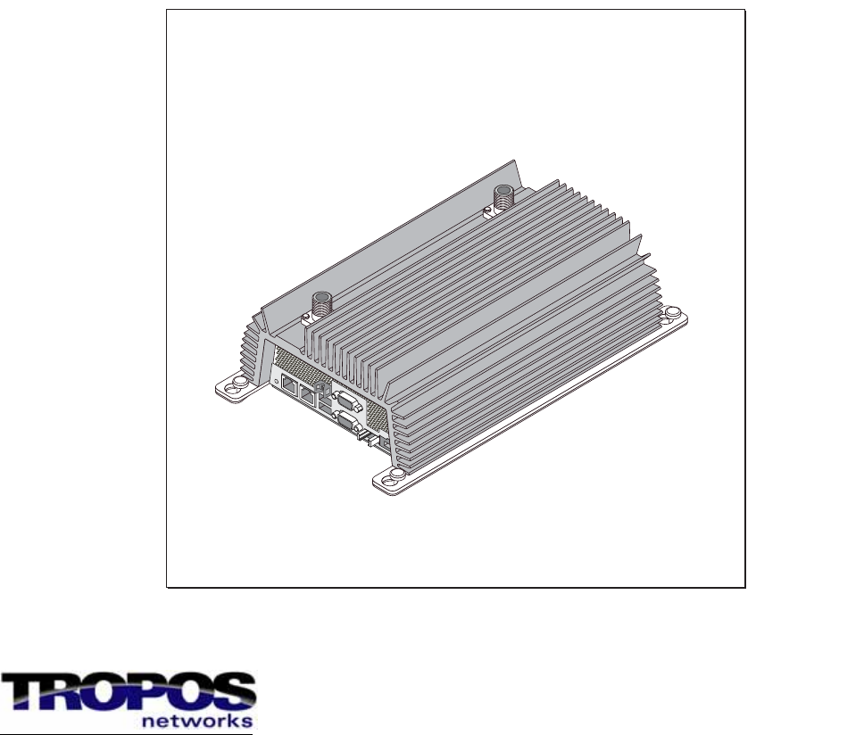
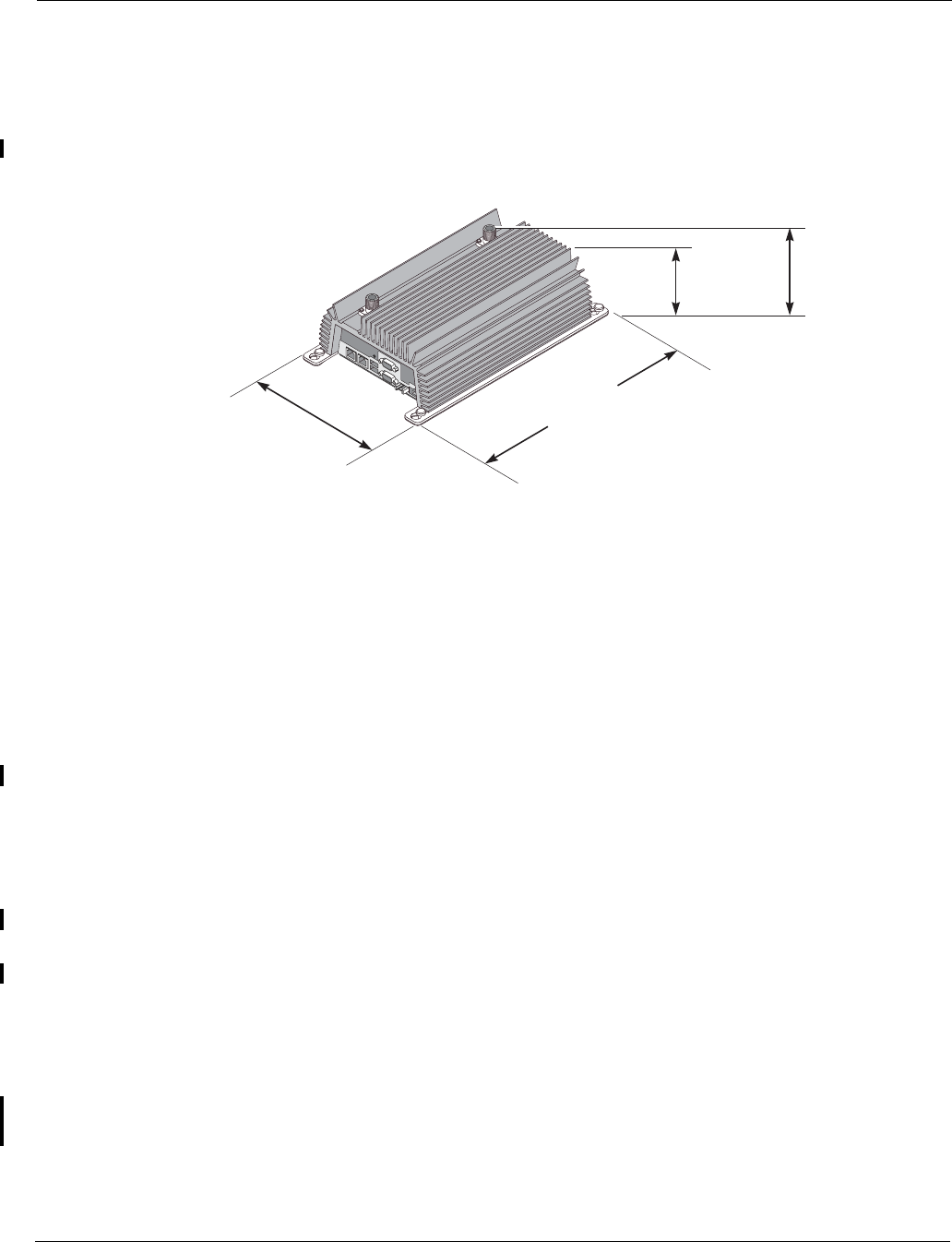
The next figure shows the router unit and dimensions.
Figure 1 Tropos 4210 MetroMesh Router
Package Contents
The Tropos 4210 router shipping package contains the following items:
Tropos 4210 MetroMesh Router
Tropos 4210 MetroMesh Router Installation Guide (this document)
2-pin power plug attached to router
Fuse attached to router
Screws, lock washers, nuts
Installation Accessories
You must supply the following accessories:
1/4-20 panhead machine screws with split lock washers
Ethernet cable to connect the router to the laptop computer you plan to use for network
access (crossover cable if no switch or hub is used)
#18 AWG wiring to connect the router to vehicle power
Antennas and antenna cables
The following items are optional:
USB GPS receiver supporting standard NMEA 0183 sentences with cable (USB connector)
Right angle antenna adapters
trp_137
Width 13.1 inches
33.3 cm
Height
3.85 inches
9.8 cm
Height
3.54 inches
9.0 cm
Depth
7.91 inches
20.1 cm

Preparing for Installation
Tropos 4210 MetroMesh Router Installation Guide 3
Selecting Locations
Tropos 4210 routers are radio devices, and as such, they are susceptible to common causes of
interference that can reduce throughput and range. To ensure the best possible performance,
follow these basic guidelines:
Install antennas on the highest area of the vehicle (roof).
If the vehicle has a light bar, install antennas at least three feet away from the bar.
It is desirable to have the antenna cables as short as possible.
Install the router away from other possible sources of 2.4 GHz WLAN interference, such as
cordless phones, spy cameras, frequency hopping (FHSS) and DSSS LAN transceivers
(non-802.11g), electronic news gathering video links, radars, amateur radios, land mobile
radio services, local government sites (such as law enforcement), fixed microwave services,
local TV transmission and private fixed point transmitters).
The router is not weather-proofed, so install only in protected interior locations.
Choose a splash-resistant mounting surface that is at least 13 inches by 8 inches to provide
sufficient space to screw the router into the surface. See FIGURE. It is not necessary to level the
unit.
The Tropos 4210 router contains integral ESD protection and vehicle power conditioning, so
external protection is not required.
Antenna Options
You can purchase any of the Tropos-approved, cable-attached antennas that are listed in
“Ordering Information” on page 17. Omni-directional antennas are best for systems requiring a
signal distribution in more than one direction. To comply with regulatory RF exposure limits,
locate antennas a minimum distance of 7.9 inches (20cm) from people. It is possible to use a
single antenna; however, two antennas are strongly recommended.
Note
Only use antennas that are approved by Tropos. Operating the unit with non-qualified
antennas is a violation of U.S. FCC Rules Part 15.203(c), Code of Federal Regulations, Title
47.
Preparing for Installation
Tropos 4210 MetroMesh Router Installation Guide 4
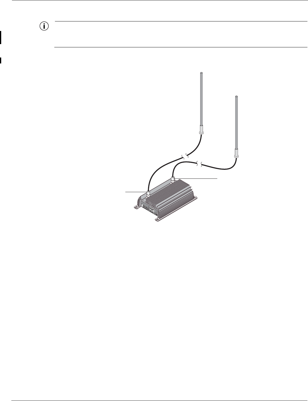
Note
The device and the antennas must not be co-located or operate in conjunction with any
other antenna or transmitter.
Figure 2 Tropos 4210 MetroMesh Routerwith Cable-Attached Antennas
RF Planning Guidelines
Tropos wireless routing technology is embedded in each Tropos 4210 MobileMesh router,
allowing each router to work in almost any environment and with a wide range of network
topologies. To maximize coverage range, locate the router in wireless-friendly areas. Try not to
place them in areas that can block or interfere with transmission. 802.11g devices transmit in the
2.4 GHz frequency spectrum. This spectrum is shared by devices such as microwave ovens,
portable phones, intercom systems and wireless alarm systems. Place each router in a location at
least 15 to 20 feet from any other transmitter to prevent the possibility of interference.
trp_128
Cables
from antennas
to unit
Aux
Tx/Rx antenna
Main
Tx/Rx antenna
Preparing for Installation
Tropos 4210 MetroMesh Router Installation Guide 5
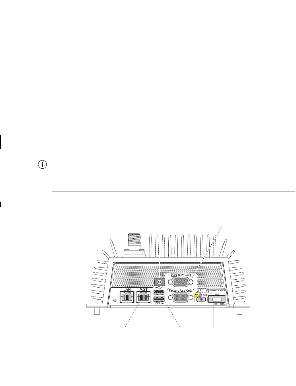
Cable Connections and Power
Figure 3 shows the power and connector ports on the side panel of the Tropos 4210 router:
The status indicator is red when the router is plugged in and has power. It is green when the
router has a working IP address and network connectivity.
The Ethernet Management (MGT) port is used to connect the router to the laptop computer
that is used for network access. The LAN port is not currently used for the Tropos 4210
router.
There are two USB ports, either one of which can be used to connect a GPS receiver.
There are two RS-232 serial ports, one of which can be used to connect to a client PC. One
RS-232 port is reserved for factory use.
The fuse is user replaceable (see “Fuse Replacement” on page 11).
The power plug accepts #18AWG wire.
The Tropos 4210 router is designed to be used with negative ground systems, such as motor
vehicle power. There is no internal battery back-up, so the vehicle must be powered for the
router to operate.
Note
The Tropos 4210 router does not have a power switch. The router is powered when the
power plug is attached and then connected to vehicle power. To remove power from an
installed router, remove the power plug, remove the fuse, or turn off vehicle power.
Figure 3 Connector Panel
trp_129
RJ-45 (Management) port
to client USB port
GPS in
RS-232 port
GPS out
Ziptie
holder
Power
connection
Fuse
LED
Installing the Tropos 4210 MetroMesh Router
Tropos 4210 MetroMesh Router Installation Guide 6
Installing the Tropos 4210 MetroMesh Router
Follow these steps to install the Tropos 4210 router:
1. Remove the router from the shipping box.
2. Drill four holes with a 7, 8, or 9 drill bit to create 0.203-inch holes in the mounting surface.
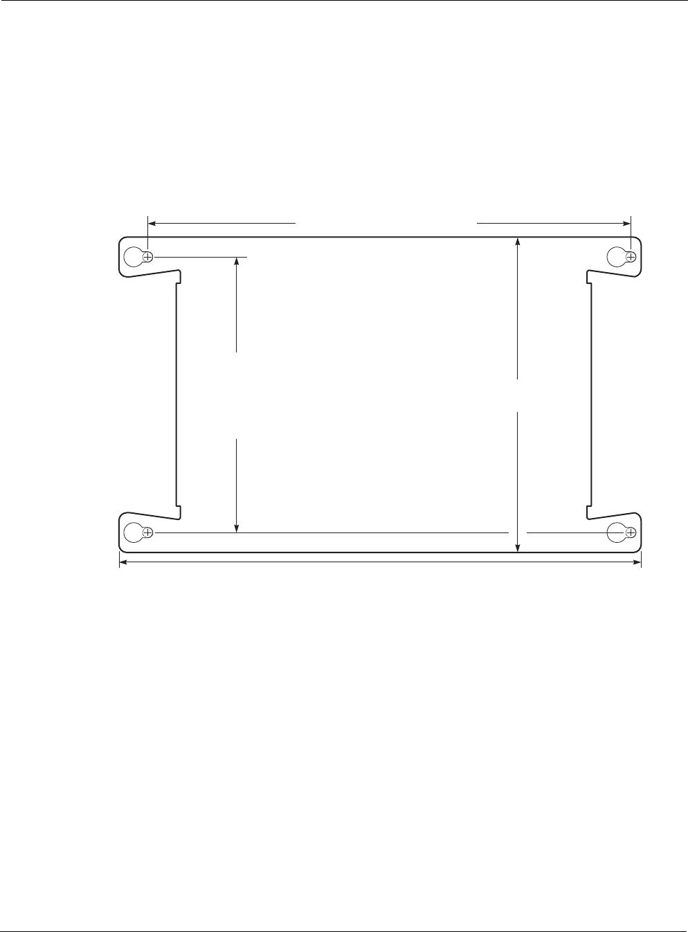
Refer to Figure 4 for the mounting dimensions.
Figure 4 Preparing the Mounting Surface
tr
p
127
13.1 inches, 33.3 cm
Drill holes for mounting bolts or screws
12.12 inches, 14.66 cm on center
7.91 inches,
20.1 cm
The recommended fastener
is a 1/4"-20 panhead machine screw.
Drill holes
for mounting
bolts or screws,
6.91 inches,
17.55 cm
on center
Installing the Tropos 4210 MetroMesh Router
Tropos 4210 MetroMesh Router Installation Guide 7
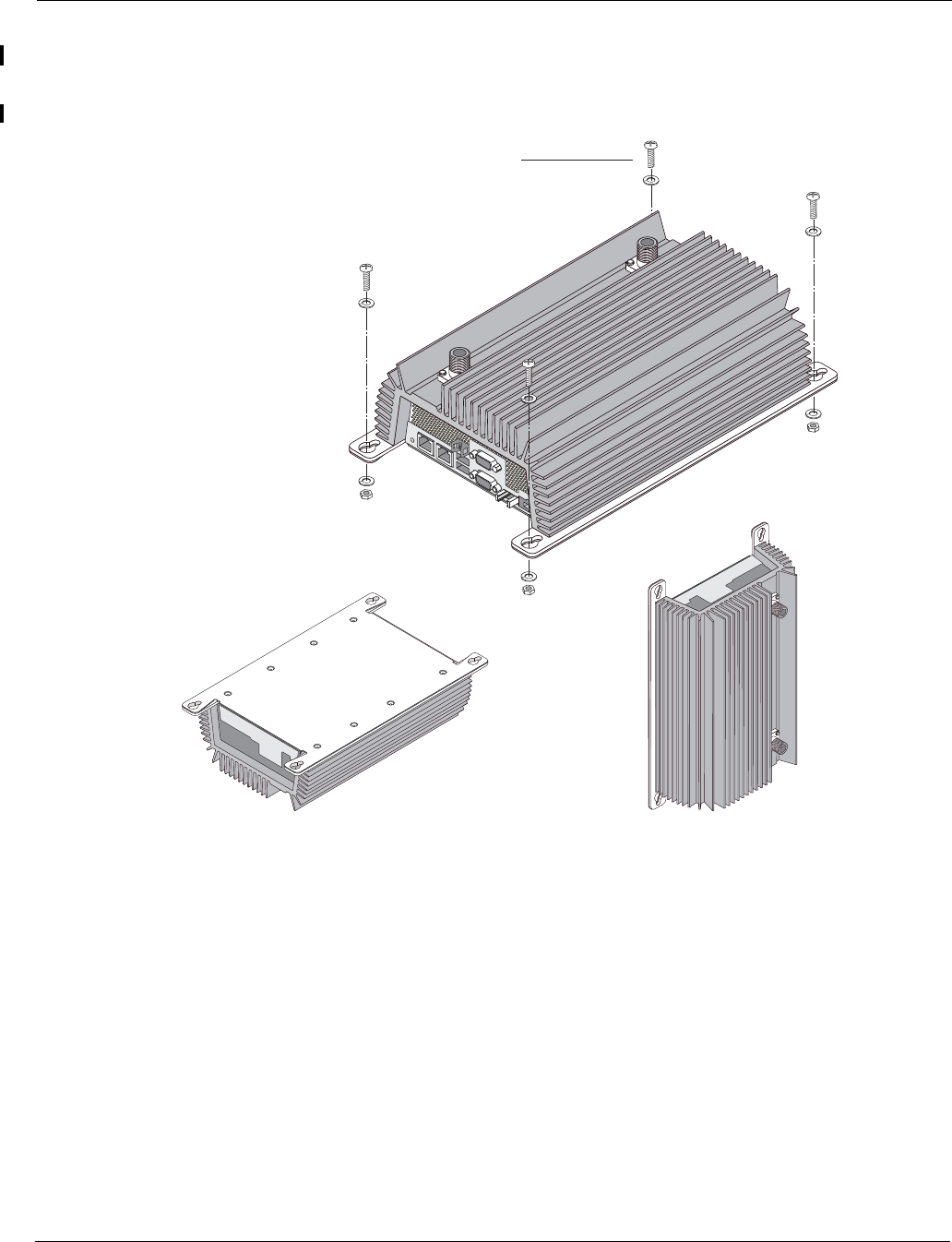
3. Screw the router to the mounting surface using 1/4”-20 panhead screws and lock washers
(Figure 5).
Figure 5 Attaching the Router to a Mounting Surface
trp_126
4 bolts
or
sheet metal screws
Preferred orientation
OK
OK
Installing the Tropos 4210 MetroMesh Router
Tropos 4210 MetroMesh Router Installation Guide 8
4. Attach antennas according to the instructions shipped with the antennas (see Figure 2 on
page 4).
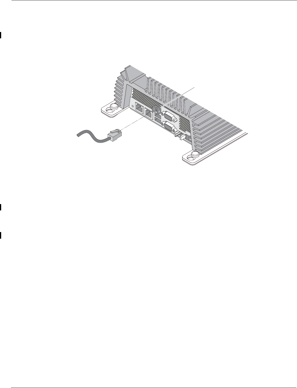
5. Connect a standard Ethernet crossover cable with RJ45 connectors from the Management
port on the route to the Ethernet port on the client computer (Figure 6).
Figure 6 Ethernet Cable Connection
6. If you plan to use a GPS receiver, mount the receiver according to the instructions shipped
with the receiver. Connect the receiver cable to one of the USB ports on the router.
7. Use a small flat-head screw driver, if necessary, to remove the screws that attach the 2-pin
power plug to the router.
8. For vibration security, use the ziptie to secure the RJ45 and USB connectors.
trp_130
Connection to client
(RJ-45)
Ziptie
holder
Remote Indicator
Tropos 4210 MetroMesh Router Installation Guide 9
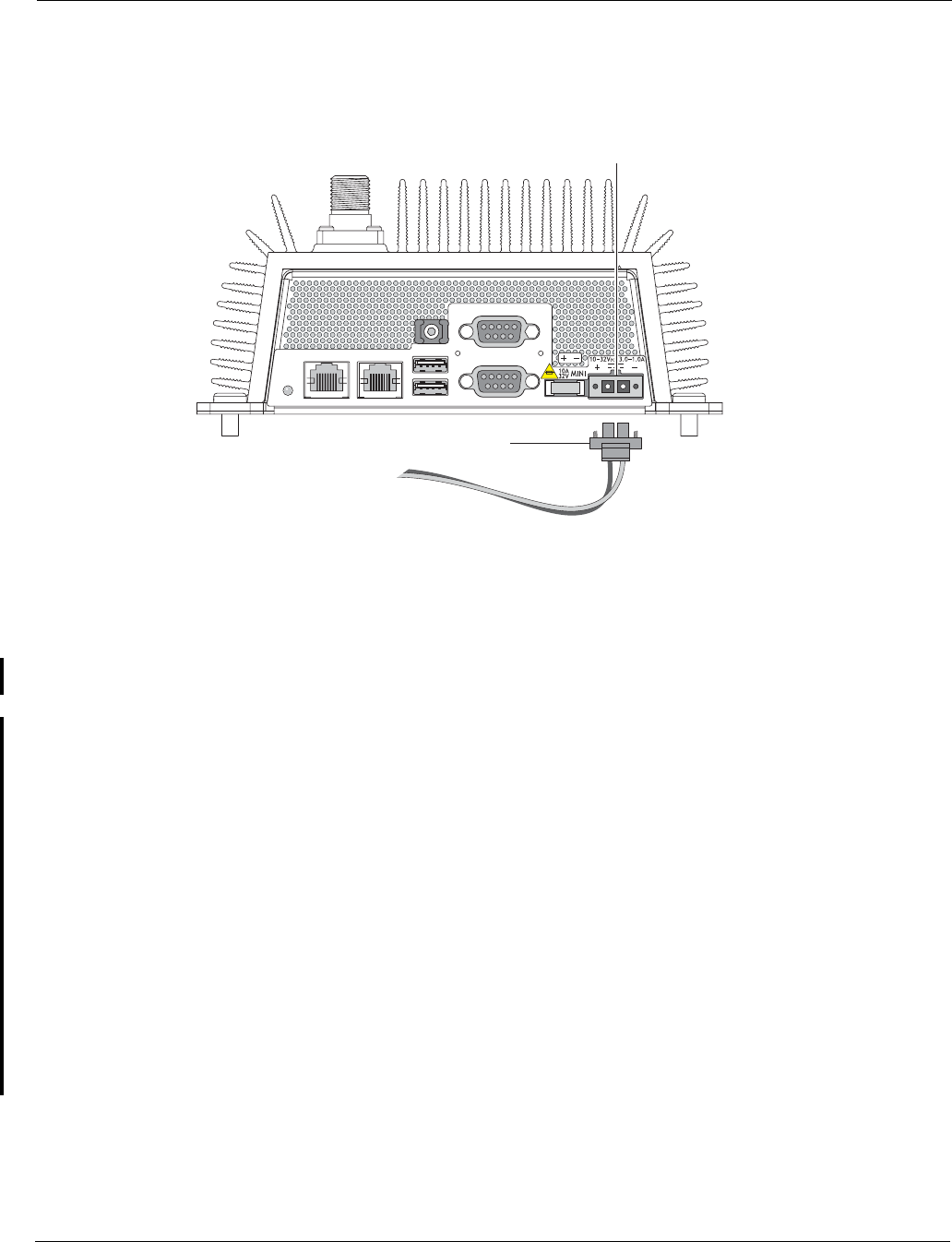
9. Trim 1/4-inch from the end of the #18AWG wire. Attach the red wire to the + side of the
power plug and the black wire to the - side.
Figure 7 Power Plug Connection
10. Return the power plug to its location on the router and screw down tightly. Note that the unit
is powered as soon as the plug is connected and the other ends of the power wires are
attached to vehicle power.
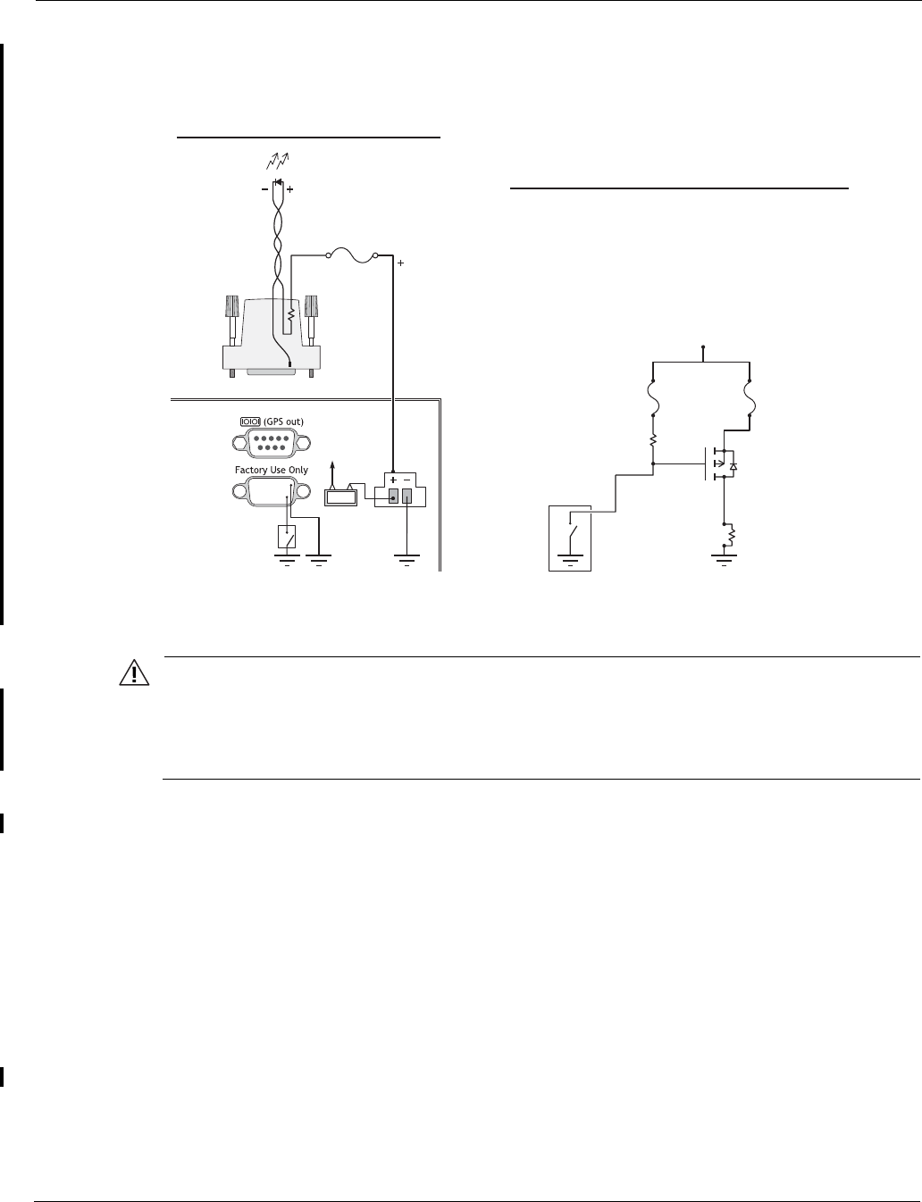
Remote Indicator
The Mesh Link Remote Indicator is a optional indicator that allows a user to determine whether
the Tropos 4210 router is connected to the Tropos network without looking at the status LED.
The indicator is assigned to pin 9 of the bottom Factory Use Only serial connector.
The Mesh Link Remote Indicator functions as follows:
If the 4210 is not connected to the network: (the router is booting or off, or there is no RF
signal), pin 9 is electrically disconnected from pin 5 (ground). This state corresponds to the
status light being off or red.
If the 4210 is connected to the network, pin 9 is electrically connected to pin 5 (ground).
This state corresponds to the status LED being green)
It is a customer decision how the remote indicator should be used. Customers can set up a
custom LED indicator to show that the unit is connected, or they can connect the indicator to a
general load that turns on another device when the Tropos 4210 router is connected to the
network. In either case, installing and operating the indicator requires knowledge and skill in
basic electronics, wiring, and cable assembly. Figure 8 is a schematic drawing of the indicator.
trp_133
Power connection
Terminal block
10
Power wiring
Service Instructions
Tropos 4210 MetroMesh Router Installation Guide 10
Figure 8 Remote Indicator Schematic
Caution
Voltage on pin 9 must always be greater than the voltage at pin 5 (ground). Pin 5 is
electrically connected to the chassis ground (negative ground). Maximum current from
pin 9 to pin 5 is 50mA. Maximum voltage on pin 9 at any time is 32V (the same as for
the Tropos 4210 router.) Exceeding these maximums can damage the remote indicator.
Service Instructions
This section contains service information for the Tropos 4210 router.
Resetting the Router
To perform a hardware reset of the router, unplug the router, pull the fuse out, or turn off the
vehicle power. Wait 10 seconds and then reconnect the plug, fuse, or vehicle power.
trp_135
For Larger Loads (> 50mA)
4210
4210 side
0.5A inline
fast-acting fuse
LED
Remote indicator
switch
15432
69 7.5A
87
Remote
indicator
switch
Pin 9
RL load
Power PFET
(> 32V rating)
(> fuse current rating)
Load fuse
(depends on load,
protects PFET)
R2
R1
4.7K
typical
1.5K
typical
User DB-9
hood
0.5A
fast-acting
Vehicle + (32V max)
9
Basic LED Operation
Service Instructions
Tropos 4210 MetroMesh Router Installation Guide 11
To reset the router configuration to factory defaults, use the Tropos Configuration Utility, as
described in the Tropos Networks User Guide.
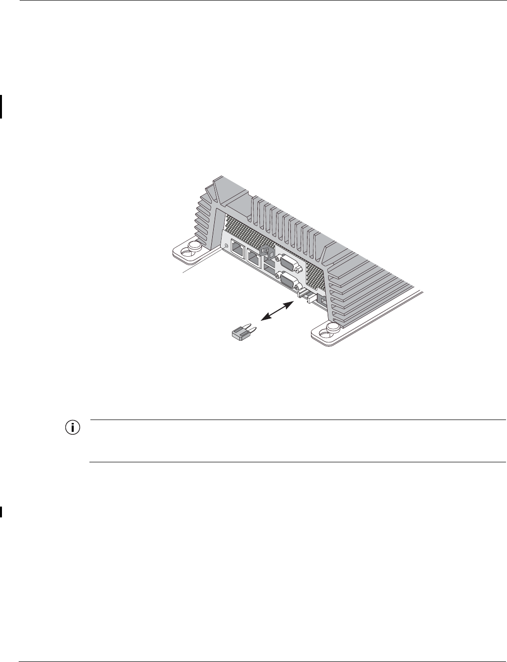
Fuse Replacement
The fuse is located to the right of the power plug. The transparent red color enables you to detect
when the fuse has blown. Use needle-nose pliers or a fuse puller to pull the fuse out. Push the
new fuse firmly into the fuse socket. To confirm that the new fuse is working, check the status
light on the left side of the panel (see Figure 9).
Figure 9 Fuse Replacement
Clock Battery
Note
The router has no internal user serviceable parts. The following information is intended for
trained service personnel only.
The Tropos 5210 MetroMesh Routers have a real-time clock which is powered by a small
lithium rechargeable battery. If the real-time clock fails, return the unit to Tropos Networks for
servicing.
trp_134
Automotive
mini
fuse
LED

Tropos 4210 MetroMesh Router Installation Guide 12
2Compliance
This chapter lists notices, cautions, and warning messages required for compliance purposes. It
contains the following sections:
“FCC Notice to Users and Operators” on page 12
“Warnings and Cautions” on page 13
FCC Notice to Users and Operators
This equipment has been tested and found to comply with the limits for a Class B digital device,
pursuant to Part 15 of the FCC Rules. These limits are designed to provide reasonable protection
against harmful interference when the equipment is operated in a commercial environment. This
equipment generates, uses, and can radiate radio frequency energy and, if not installed and used
in accordance with the instruction manual, may cause harmful interference to radio
communications. Operation of this equipment in a residential area is likely to cause harmful
interference, in which case the user will be required to correct the interference at his own
expense. If this equipment does cause interference to radio or television reception, which can be
determined by turning the equipment off and on, the user is encouraged to correct the
interference by using one of the following measures:
Reorient or relocate the receiving antenna.
Increase separation between the equipment and receiver.
Connect the equipment to an outlet on a circuit different from that to which the receiver is
connected.
Consult the dealer or an experienced radio/TV technician.
This Part 15 radio device operates on a non-interference basis with other devices operating at
this frequency. Any changes or modification to said product not expressly approved by Tropos
Networks could void the user's authority to operate this device.

Warnings and Cautions
Tropos 4210 MetroMesh Router Installation Guide 13
Warnings and Cautions
Warning
It is illegal to modify the construction of this product. Modifying the operating frequency or
enhancing the transmit output power through the use of external amplifiers or other
equipment is specifically disallowed by the “Telecommunications Act.”
Warning
This device is for indoor use with conditions that no harmful interference to authorized radio
stations results from the operation of this device. This device shall not influence aircraft
security and/or interfere with legal communications as defined in the “Telecommunications
Act.” If this device is found to cause interference, the operator of this equipment shall cease
operating this device immediately until no interference is achieved.

Tropos 4210 MetroMesh Router Installation Guide 14
3Product Specifications
This chapter contains the product specifications for the Tropos 4210 MetroMesh Router:
“Physical Specifications” on page 14
“Interfaces” on page 15
“Power Options / Consumption” on page 16
“Certifications” on page 16
Table 1 Physical Specifications
Physical Dimensions Height Width Depth
Inches 3.85 13.1 7.91
Centimeters 9.8 33.3 20.1
Weight
lbs - maximum 9.0 Includes all brackets
Kg - maximum 6.35
Temperature Min Max
AC Powered Operating Range -40C 70C
Storage Range -45C 85C
Color Unpainted metal
Shock and Vibration
Operational: MIL-STD 810g
Transportation: ISTA 2A
Random Bounce
Random Vibration
6 Corner Drop Test

Tropos 4210 MetroMesh Router Installation Guide 15
Table 2 Interfaces
Data Interface Maximum Distance (ft) Connector
IEEE 802.3 10/100BaseT 1300 (10BaseT Half and Full
Duplex Setting)
300 (100BaseT Half and Full
Duplex Setting)
RJ45
Management Interface Maximum Distance (ft) Connector
IEEE 802.3 10/100Base T 1300 (10BaseT
Full Duplex Setting)
300 (100BaseT
Full Duplex Setting)
RJ45
Wireless Interface
Standard IEEE 802.11b/g Wi-Fi
Frequency Range 2400 to 2485 MHz ISM Band
Modulation DSSS; DBPSK @ 1 Mbps,
DQPSK @ 2 Mbps,
CCK @ 5.5 and 11 Mbps
OFDM @ 54, 48, 36, 24, 18, 12, 6
Rx Sensitivity -100dBm (1 Mbps)
-95dBm (2 Mbps)
-93dBm (5.5 Mbps)
-91dBm (11 Mbps)
-94dBm (6 Mbps)
-93dBm (9 Mbps)
-92dBm (12 Mbps)
-89dBm (18 Mbps)
-86dBm (24 Mbps)
-83dBm (36 Mbps)
-78dBm (48 Mbps)
-76dBm (54 Mbps)

Tropos 4210 MetroMesh Router Installation Guide 16
Rx Saturation
Maximum Power at Antenna Port
-5dBm (1 Mbps)
-5dBm (2 Mbps)
-5dBm (5.5 Mbps)
-5dBm (11 Mbps)
-5dBm (6 Mbps)
-5dBm (9 Mbps)
-5dBm (12 Mbps)
-10dBm (18 Mbps)
-30dBm (24 Mbps)
-35dBm (36 Mbps)
-35dBm (48 Mbps)
-35dBm (54 Mbps)
Antennas
Antennas External
Antenna Diversity Transmit/Receive
Impedance 50 ohms
VSWR 1.5 : 1
Connectors (two) N (female)
Indicator - Status Lamp Red/Green/Blue
Table 3 Power Options / Consumption
DC: 10.0-32.0 VDC 20W/30S typical/max
Polarity protected
Negative return - common chassis
ground
23W/60W typical/max
Antenna Protection <= 0.5µJ for 3kA @ 8/20µS Waveform
EN61000-4-2 Level 4 ESD Immunity
EN61000-4-5 Level 4 Surge Immunity
Fuse Automotive mini-blade 32 VDC 7.5A
Table 4 Certifications
Certifications
U.S. CFR 47 FCC Part 15.C; Class B
Table 2 Interfaces (continued)

Tropos 5210 MetroMesh Router Installation Guide 17
4Ordering Information
Table 5 contains ordering information for the Tropos 4210 Mobile MetroMesh router and related
equipment. These items can be ordered from Tropos Networks, Inc.
Table 5 Tropos Ordering Information
Part No. Description
42102100 Tropos 4210 Mobile MetroMesh Router, variable power, N connectors
RC009100 Right angle N-connector adapter: male/female
AN074090 One vehicle mounted 7.4dBi omni antenna and cable kit
AN074091 One vehicle magnetic mounted 7.4dBi omni antenna and cable kit
AN074095 One vehicle mounted 7.4dBi omni antenna (cable kit not included)
AN050090 One vehicle mounted 5.0dBi omni antenna and cable kit
AN050091 One vehicle magnetic mounted 5.0dBi omni antenna and cable kit
AN050095 One vehicle mounted 5.0dBi omni antenna (cable kit not included)
GR000350 Vehicle mounted GPS receiver with USB interface and cable
PS024002 24Vdc AC/DC power supply with adapter cable
Littlefuse
297010 or
equivalent
ATO-mini fuse, 32Vdc 7.5A

Tropos 4210 MetroMesh Router Installation Guide 18
5Antenna Accessories
Table 6 contains accessory ordering information for mobile antennas:
Table 6 Mobile Antenna Accessories
Part Number Description Supplier
SF-245SPR 7.4dBi mobile antenna, N connector, black www.cometantenna.com
MG-4N Magnetic mount - N for 7.4dBi mobile antenna www.cometantenna.com
5D4N Bulkhead mount for 7.4dBi mobile antenna www.cometantenna.com

Tropos 4210 MetroMesh Router Installation Guide 19
Acronyms
The following acronyms are used in this document.
Table 7 Acronyms
AASHTO American Association of State Highway and Transportation Officials
ANSI American National Standards Institute
AWG American Wire Gauge
C Celsius
CAT Category
CCK Complementary Code Keying
CE Conformite Europeene
CFR Code of Federal Regulations
CISPR International Special Committee on Radio Interference
CSA Canadian Standard Association
dB Decibels
dBi Decibels Relative to an Isotropic Radiator
dBm Decibels Referred to 1 Milliwatt
DBPSK Differential-Binary Phase-Shift Keying
DC Direct Current
DGT Directorate General of Telecommunications (Taiwan)
DQPSK Differential-Quadrature Phase-Shift Keying
DSSS Direct-Sequence Spread Spectrum
EFT Electrically Fast Transients

Tropos 4210 MetroMesh Router Installation Guide 20
EMC Electromagnetic Compatibility
EN IEC standard
ESD Electrostatic Discharge
ETSI European Telecommunications Standards Institute
FCC Federal Communications Commission
FHSS Frequency Hopping Spread Spectrum
Hz Hertz
IEC International Electrotechnical Commission
IEEE Institute of Electrical and Electronics Engineers
IP67 Ingress Protection Standard
ISM Instrumentation, Scientific, and Medical band
ISTA International Safe Transit Association
LAN Local Area Network
Mbps Megabits Per Second
MHz Megahertz
MIL-STD Military Standard
MPHPT Ministry of Public Management, Home Affairs, Posts and Telecommunications (Japan)
N Neutral
NEC National Electrical Code
NEMA National Electrical Manufacturers Association
NMEA National Marine Electronics Association
OFDM Orthogonal Frequency Division Multiplexing
RJ45 Registered Jack 45
RSS Received Signal Strength
Rx Receive
RXD Receive Data
TUV Technical Inspection Association
Table 7 Acronyms (continued)

Tropos 4210 MetroMesh Router Installation Guide 21
Tx Transmit
TXD Transmit Data
UL Underwriters’ Laboratories
UPS Uninterruptible Power Supply
VAC Voltage (Alternating Current)
VCCI Voluntary Control Council for Interference (Japan)
VDC Voltage (Direct Current)
VSWR Voltage Standing Wave Ratio
WWatts
Table 7 Acronyms (continued)

Tropos 5210 MetroMesh Router Installation Guide 1
Index
A
antenna type and placement 11
antennas
approved configurations 12
distances from people 3
options 3
B
building materials 11
D
data rate considerations 11
diversity 11
I
installation
Tropos router 1
installation considerations
antenna options 3
site surveys 11
O
obstructions 11
P
physical environment 11
product specifications 14
S
site surveys 11
specifications 14