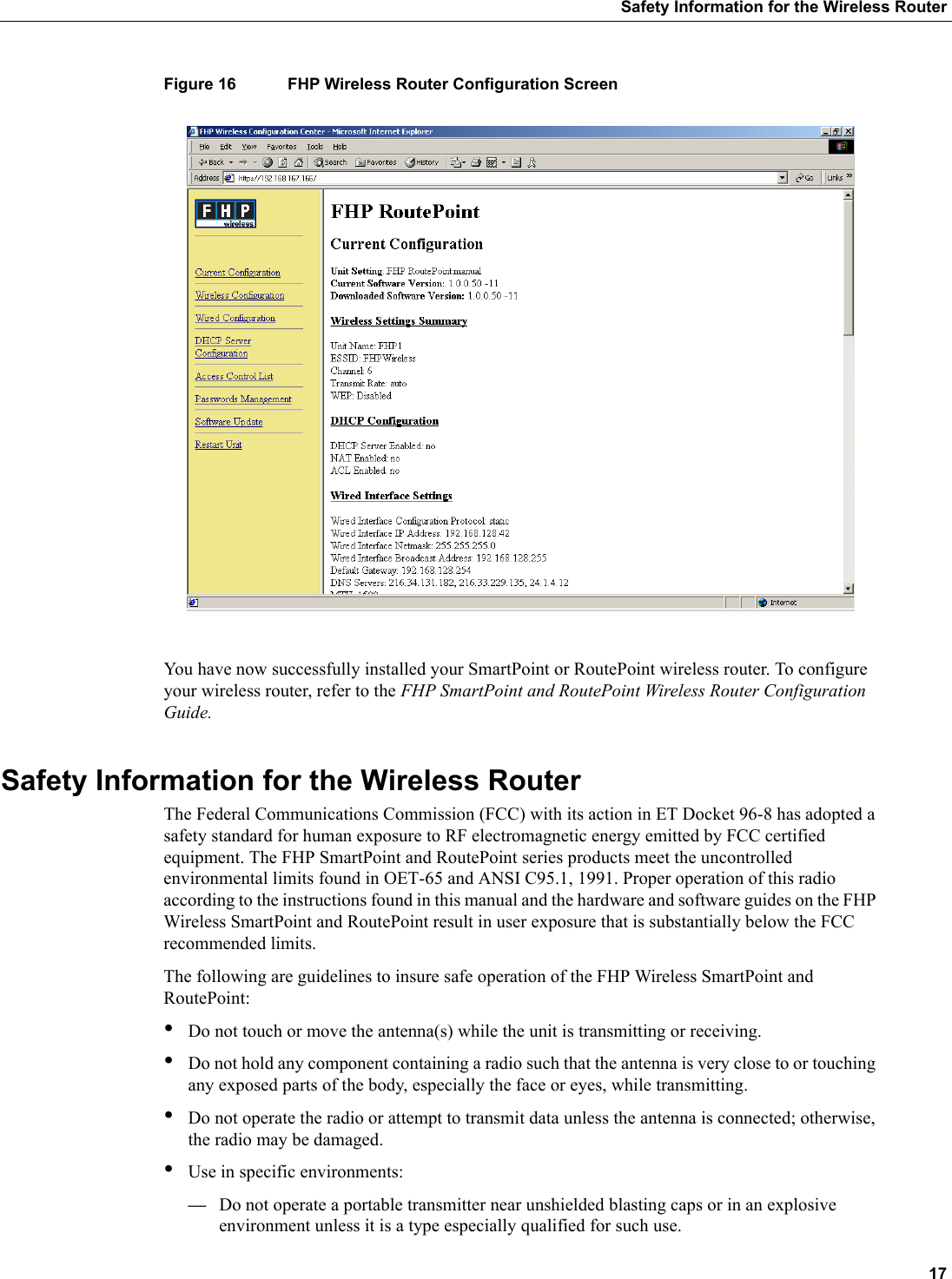
ABB Enterprise Software SP-01-00C-C Smartpoint/Routepoint Wireless Router User Manual FHP New Hardware Installation Guide

Tropos Networks, Inc. Smartpoint/Routepoint Wireless Router FHP New Hardware Installation Guide

User Manual

10039 Rev. AFHP Wireless, Inc.All rights reserved.Suite 304San Mateo, CA 94402USA1710 South Amphlett BoulevardFHP Wireless, Inc.Copyright © 2002FHP SmartPoint and RoutePoint Wireless RouterProfessional Hardware Installation GuideFor Model Numbers: SP-01-00C-C-N-00 and RP-01-00C-C-N-00
2FCC Notice to Users and OperatorsFCC Notice to Users and OperatorsThe SmartPointTM and RoutePointTM wireless routers comply with Part 15 of the FCC rules. Operation of the SmartPoint and RoutePoint wireless routers is subject to the following two conditions:1This device may not cause harmful interference, and2This device must accept any interference received, including interference that may cause undesired operation.This equipment has been tested and found to comply with the limits for a Class A digital device, pursuant to Part 15 of the FCC Rules. These limits are designed to provide reasonable protection against harmful interference when the equipment is operated in a commercial environment. This equipment generates, uses, and can radiate radio frequency energy and, if not installed and used in accordance with the instruction manual, may cause harmful interference to radio communications. Operation of this equipment in a residential area is likely to cause harmful interference, in which case the user will be required to correct the interference at his own expense. If this equipment does cause interference to radio or television reception, which can be determined by turning the equipment off and on, the user is encouraged to correct the interference by using one of the following measures:•Reorient or relocate the receiving antenna. •Increase separation between the equipment and receiver. •Connect the equipment to an outlet on a circuit different from that to which the receiver is connected. •Consult the dealer or an experienced radio/TV technician.Caution This Part 15 radio device operates on a non-interference basis with other devices operating at this frequency. Any changes or modification to said product not expressly approved by FHP Wireless could void the user's authority to operate this device.IntroductionThe FHP SmartPoint and RoutePoint Wireless Router Professional Hardware Installation Guide provides installation instructions for the SmartPoint and RoutePoint wireless routers and is intended for a trained technical professional. Operation and network configuration for the SmartPoint and RoutePoint wireless routers are detailed in the FHP SmartPoint and RoutePoint Wireless Router Configuration Guide. The installation instructions in this guide apply to the following SmartPoint and RoutePoint wireless router model numbers:•FHP RoutePoint RP-01-00C-C-N-00 (Antennas not provided)•FHP SmartPoint SP-01-00C-C-N-00 (Antennas not provided)
 3About FHP Wireless NetworkingThe SmartPoint and RoutePoint wireless routers may be configured with one of the following antenna options. (Antennas ordered separately.)•AN-015-OM-UM-N  1.5 dBi omni-directional unit mounted antenna; N (male) connector•AN-050-OM-UM-N  5.0 dBi omni-directional unit mounted antenna; N (male) connector•AN-074-OM-UM-N  7.4 dBi omni-directional unit mounted antenna; N (male) connector•AN-120-SP-WM-N 12.0 dBi 90 degree sector patch wall mounted patch antenna; N (male) connectorNote The FHP SmartPoint and RoutePoint wireless routers must be installed by a trained professional, value added reseller, or systems integrator who is familiar with RF cell planning issues and the regulatory limits defined by the FCC for RF exposure, specifically those limits outlined in sections 1.1307.About FHP Wireless NetworkingTo better understand how an FHP wireless networking system works, it is helpful to compare it to more common 802.11b systems. Typical 802.11b access points must be “hardwired” to your internal network. To install a typical access point, you connect the Ethernet port on the access point to a hub or switch port on your internal network. Each access point acts as an extension to your wired network by serving as a bridge, connecting clients to your internal network. Figure 1 is an example of a standard access point network.Figure 1 Standard Access Point NetworkThe FHP SmartPoint and RoutePoint wireless routers function very differently than traditional, wired-access points. For example, for a small or large FHP network installation only a small number of SmartPoint and RoutePoint wireless routers need to be hardwired to your internal network. In fact, only one RoutePoint device needs to be connected to your internal network to provide connectivity fhp_003Wireless userAP APAPYour "wired"network
4Introductionfor wireless users. For many wireless networks, one wired RoutePoint gateway is all that is needed. For added redundancy and additional bandwidth for larger wireless networks, additional gateways can be added as necessary. Non-wired SmartPoint wireless routers (nodes) function independently to form large, routed wireless networks. All you need is power for the SmartPoint wireless routers, and you can expand your wireless network by adding nodes to the network. In this way, you can build large, routed wireless networks covering areas traditionally hard to reach due to the hardwire limitation of the Ethernet connections. SmartPoint and RoutePoint wireless routers automatically configure themselves to form clusters around each wired gateway. No user intervention is required and no knowledge of routing protocols is necessary to configure your network. Each device needs some basic configuration information (ESSID, WEP Key, and so on), but other than that, your wireless network configures itself and performs all routing functions in the background. Even the IP addresses on the wireless network are automatically configured and preset at the factory, enabling true “plug-and-play” configuration of your FHP SmartPoint or RoutePoint wireless router. Note Refer to the FHP SmartPoint and RoutePoint Wireless Router Configuration Guide for software configuration information.Figure 2 shows a sample FHP SmartPoint and RoutePoint network installation.Figure 2 FHP SmartPoint and RoutePoint Wireless Router Networkfhp_004Wireless userFHP WirelessSmartPoint NodeFHP WirelessRoutePoint GatewayFHP WirelessSmartPoint NodeYour "wired"network
 5Installation GuidelinesInstallation GuidelinesThis section describes installation procedures for your SmartPoint and RoutePoint wireless routers. It also describes important considerations in selecting the wireless router location, wall mounting options, and power and LAN connections.Selecting Locations for RoutePoint Gateways and SmartPoint NodesOne of the most important things to keep in mind when installing your SmartPoint and RoutePoint wireless routers is the fact that 10/100 Base-T Ethernet using category 5 network cabling has a 100 meter distance limitation. Basic GuidelinesThe SmartPoint and RoutePoint wireless routers are radio devices. Therefore they are susceptible to common causes of interference that can reduce throughput and range. To ensure the best possible performance, follow these basic guidelines:•Install the SmartPoint or RoutePoint wireless router antennas in an area where trees, buildings, and large steel structures such as shelving units, bookcases, and filing cabinets do not obstruct radio signals to and from the antenna. Locating the antennas for direct line-of-sight operation is best. •Install the SmartPoint or RoutePoint wireless router away from microwave ovens or other devices operating in the 2.4 GHz frequency range. Microwave ovens operate on the same frequency as the wireless router and can cause signal interference. •Install the SmartPoint or RoutePoint wireless router away from other possible sources of 2.4 GHz WLAN interference, such as cordless phones, home spy cameras, frequency hopping (FHSS) and DSSS LAN transceivers (non-802.11b), electronic news gathering video links, radars, amateur radios, land mobile radio services, local government sites (such as law enforcement), fixed microwave services, local TV transmission and private fixed point transmitters, and excited sodium lamps (some street lighting).Installation in Air-Handling EnvironmentsThe SmartPoint and RoutePoint wireless routers are UL2043 certified which means that they are suitable for use in air-handling spaces.Antenna OptionsThe SmartPoint and RoutePoint wireless routers support external antennas with omni-directional or directional capabilities. Omni-directional antennas are best for systems requiring a signal distribution in more than one direction. High-gain directional antennas are best suited for covering longer distances in a fixed direction. Note Only use antennas supplied by FHP Wireless with your wireless routers. Operating the SmartPoint and RoutePoint wireless routers with a non-qualified antenna may be in violation of FCC Rules Part 15.203(c), Code of Federal Regulations, Title 47.
6Installation GuidelinesSite SurveysBecause of differences in component configuration, placement, and physical environment, every network application is a unique installation. Before installing multiple SmartPoint and RoutePoint wireless routers, you should perform a site survey to determine the optimum utilization of networking components and to maximize range, coverage, and network performance.Consider the following operating and environmental conditions when performing a site survey:•Data rates—Sensitivity and range are inversely proportional to data bit rates. The maximum radio range is achieved at the lowest workable data rate. A decrease in receiver threshold sensitivity occurs as the radio data increases. •Antenna type and placement—Proper antenna configuration is a critical factor in maximizing radio range. As a general rule, range increases in proportion to antenna height and gain. •Physical environment—Clear or open areas provide better radio range than closed or filled areas. Also, the less cluttered the operating environment, the greater the range. •Obstructions—A physical obstruction, such as a building or tree, can block or hinder communication between SmartPoint and RoutePoint wireless routers. Avoid locating the antennas in a location where there is an obstruction between the sending and receiving antennas. •Building materials—Radio penetration is greatly influenced by the building material used in construction. For example, drywall construction allows greater range than concrete blocks. Metal or steel construction is a barrier to radio signals.Wireless Coverage and RangeThe wireless network depends on performing multi-hop data transfers across numerous SmartPoints in order to provide connectivity to a RoutePoint gateway. SmartPoint nodes and RoutePoint gateways need to be distanced from each other in such a way that one device can communicate with other SmartPoint and RoutePoint wireless routers over the RF wireless interface. On the other hand, clustering too many SmartPoint or RoutePoint wireless routers together within a small geographic area may create a situation where the SmartPoint and RoutePoint wireless routers generate excessive interference with each other. In this case, throughput performance of the network may be impaired. A single SmartPoint or RoutePoint wireless router should have a partial overlapping coverage area with one or more SmartPoint or RoutePoint wireless routers. As a general rule of thumb, placing a SmartPoint or RoutePoint wireless router such that it has partial overlapping coverage area with two other SmartPoint or RoutePoint wireless routers provides adequate network redundancy while mitigating interference.SmartPoint and RoutePoint Wireless Router RF Planning GuidelinesUnique FHP wireless routing technology embedded in each SmartPoint and RoutePoint wireless router allows them to work in almost any environment and wireless network topology. To maximize coverage range you should locate them in wireless-friendly areas. Try not to place them in areas that could block or interfere with transmission. 802.11b devices transmit in the 2.4 GHz frequency spectrum. This spectrum is shared by devices such as microwave ovens, portable phones, intercom systems and wireless alarm systems. Place each SmartPoint or RoutePoint wireless router in a location at least 15 to 20 feet from any other transmitter to prevent the possibility of interference. Locating your SmartPoint and RoutePoint wireless routers high on a wall or hanging from a ceiling is a good start. This allows transmission over the entire environment or office space with minimal blocking objects. If you are trying to cover an outdoor area from inside a building, place SmartPoint
 7Preparing for Installationand RoutePoint wireless routers in front of non-metallic coated windows, or close to the outside walls of the building. Using some common sense planning to place the SmartPoint and RoutePoint wireless routers greatly increases your coverage area.Preparing for InstallationUnpackingCarefully unpack your SmartPoint or RoutePoint wireless router shipping box. The power adapter box and the mounting hardware bag are contained in the cardboard holder for the SmartPoint or RoutePoint wireless router unit, as shown in Figure 3 below. Be careful not to discard them.Figure 3 SmartPoint and RoutePoint Shipping Boxfhp_002Mounting hardware bagLarge antennas(if present)Power adapterboxFHP SmartPointSmall antennas(if present)
8Installation GuidelinesItems Included with each SmartPoint and RoutePoint Wireless RouterEach SmartPoint or RoutePoint wireless router comes with the following items:•Four 1-inch drywall screws•Four 1-inch drywall anchors•Two right angle mounting brackets•One SmartPoint or RoutePoint wireless router•One AC/DC power converter, for use at 110/120 VAC•Two antennas (optional)•One 0.5 ml capsule of Loctite® Threadlocker 242 (used to bond antenna connectors to unit)•Four #6–32 screws - phillips head•Four #6–32 screws - tamper-resistant TORX® T10-HRequired Tools and Supplies for InstallationYou need the following tools and supplies to complete the wireless router installation:•Phillips head screwdriver•Drill with 3/16 inch diameter drill bit•Stud finder•Tamper-resistant TORX key driver T10-H (if tamper-resistant TORX screws are used)•A non-switched, 110 Volt 15 Amp duplex power outlet within five feet of the SmartPoint or RoutePoint wireless router mounting location•A wood or plasterboard wall with adequate clearance to mount the SmartPoint or RoutePoint wireless routerNote In order to comply with FCC RF exposure limits, SmartPoint and RoutePoint wireless router dipole antennas should be located at a minimum distance of 7.9 inches (20cm) or more from people.Wall Mounting InstructionsThe SmartPoint and RoutePoint wireless routers can be wall mounted in the following three ways:•Edge mounted, as shown in Figure 4 •Flat mounted, as shown in Figure 5•Secure mounted, as shown in Figure 6
 9Wall Mounting InstructionsFigure 4 Edge Mounting Optionfhp_005
10Installation GuidelinesFigure 5 Flat Mounting Optionfhp_006
 11Wall Mounting InstructionsFigure 6 Secure Mounting OptionTo wall mount the SmartPoint or RoutePoint wireless router, complete the following steps:Step 1 Decide on the mounting orientation of the SmartPoint or RoutePoint wireless router. Step 2 Locate two studs on the wall using the stud finder. The SmartPoint or RoutePoint wireless router should be mounted midway between the two studs. Step 3 Drill four holes in the wall to accommodate the mounting brackets.Step 4 Push the four wall anchors into the four holes. Step 5 Screw the mounting brackets to the wall.Step 6 Screw the SmartPoint or RoutePoint wireless router to the mounting brackets.Step 7 Perform a trial installation of the antennas or antenna cables, depending on your installation.Step 8 Once you are satisfied with the trial placement of the antennas or antenna cables, remove the antenna connections from the wireless router and apply two drops of Loctite Threadlocker 242 to the antenna connector thread, as shown in Figure 7, then install the antenna or antenna cables.fhp_011After fasteningbrackets to wall,use Torx screwsto attach bracketsto SmartPoint
12Installation GuidelinesFigure 7 SmartPoint and RoutePoint Wireless Router Antenna ConnectorsConnecting Power and LANThe LAN port on your SmartPoint or RoutePoint is compatible with IEEE 802.3 af-compliant power sourcing devices, as shown in Figure 8. If you are using Power Over Ethernet you will not need to connect a separate power supply.Note When the SmartPoint or RoutePoint wireless router is installed in a plenum or air-handling space, the cables employed should be suitable under NEC article 800-50 and NFPA 262 and marked accordingly, for use in plenums and air-handling spaces with regard to smoke propagation, such as CL2-P, CL3-P, MPP or CMP.Figure 8 Power Over Ethernet OptionNote If you use the Power Over Ethernet option, make sure that the power sourcing device is IEEE 802.3 af-compliant.Follow these steps to connect a SmartPoint or RoutePoint wireless router to your network:Step 1 Attach a category 5 twisted pair patch cable to the Ethernet port labeled LAN on the SmartPoint or RoutePoint wireless router as shown in Figure 9.fhp_007Apply 2 drops of Loctite herefhp_012LAN portPower injector(not supplied by FHP)
 13Connecting Power and LANFigure 9 SmartPoint and RoutePoint Wireless Router LAN ConnectionStep 2 Connect the other end directly into your PC or laptop or to your internal network. See “Selecting Locations for RoutePoint Gateways and SmartPoint Nodes” on page 5 for more information on where to connect the SmartPoint or RoutePoint wireless router to your internal network. Step 3 If you are not using the Power Over Ethernet option, connect the supplied AC/DC adapter to the SmartPoint or RoutePoint wireless router and plug the power adapter into a standard 120V AC power outlet, as shown in Figure 10 below. Wait 2 minutes for the SmartPoint or RoutePoint to boot.Figure 10 SmartPoint and RoutePoint Wireless Router AC/DC Adapter Connection Note The DB-9 connector marked Factory Use Only is a serial port used at the factory to configure settings and software for the SmartPoint or RoutePoint wireless router. It is not necessary to use this port for configuration.fhp_008LAN port(can accept power to unit)fhp_00912Vdcjack
14Operating Your Wireless RouterOperating Your Wireless RouterThis section describes the steps required to properly configure your wireless router for use.Preparing to Access the Configuration UtilityBefore you can access the SmartPoint and RoutePoint configuration utility, you must set the IP address and subnet mask on your computer, as described in the following steps:Step 1 From the Start button, select Settings → Network and Dial-Up Connections. The Network and Dial-up Connections folder opens, as shown in Figure 11.Figure 11 Network and Dial-Up Connections FolderStep 2 Right click on the Ethernet interface for your PC, for example 10-Base-T.Step 3 Select Properties. The Properties dialog box for your interface opens, as shown in Figure 12.
 15Preparing to Access the Configuration UtilityFigure 12 Properties Dialog BoxStep 4 Select Internet Protocol (TCP/IP).Step 5 Click the Properties button. The Internet Protocol (TCP/IP) Properties dialog box opens, as shown in Figure 13.Figure 13 Internet Protocol (TCP/IP) Properties Dialog BoxStep 6 Click the Use the following IP address option.Step 7 In the IP address box, enter the following IP address:192.168.167.160Step 8 In the Subnet mask box, enter the following subnet mask:255.255.255.0
16Operating Your Wireless RouterStep 9 Click OK.Step 10 Restart your computer.Accessing the Configuration Utility To access the configuration utility, complete the following steps:Step 1 Connect your computer to the port marked Management on the SmartPoint or RoutePoint wireless router using an IEEE 802.3 RJ-45 crossover cable, as shown in Figure 14.Figure 14 SmartPoint and RoutePoint Wireless Router Management ConnectionStep 2 Start a web browser (Explorer or Netscape) on your PC.Step 3 In the URL window of the browser, enter the management IP address of the SmartPoint or RoutePoint wireless router:https://192.168.167.166Step 4 When the Enter Network Password dialog box appears, enter the username admin and password fhp, as shown in Figure 15, then click OK.Figure 15 Enter Network Password Dialog BoxStep 5 Once properly logged in, the FHP Wireless Configuration Center screen opens, as shown in Figure 16.fhp_010Management port
 17Safety Information for the Wireless RouterFigure 16 FHP Wireless Router Configuration ScreenYou have now successfully installed your SmartPoint or RoutePoint wireless router. To configure your wireless router, refer to the FHP SmartPoint and RoutePoint Wireless Router Configuration Guide.Safety Information for the Wireless RouterThe Federal Communications Commission (FCC) with its action in ET Docket 96-8 has adopted a safety standard for human exposure to RF electromagnetic energy emitted by FCC certified equipment. The FHP SmartPoint and RoutePoint series products meet the uncontrolled environmental limits found in OET-65 and ANSI C95.1, 1991. Proper operation of this radio according to the instructions found in this manual and the hardware and software guides on the FHP Wireless SmartPoint and RoutePoint result in user exposure that is substantially below the FCC recommended limits.The following are guidelines to insure safe operation of the FHP Wireless SmartPoint and RoutePoint:•Do not touch or move the antenna(s) while the unit is transmitting or receiving.•Do not hold any component containing a radio such that the antenna is very close to or touching any exposed parts of the body, especially the face or eyes, while transmitting. •Do not operate the radio or attempt to transmit data unless the antenna is connected; otherwise, the radio may be damaged.•Use in specific environments:—Do not operate a portable transmitter near unshielded blasting caps or in an explosive environment unless it is a type especially qualified for such use.
18Service Instructions—The use of wireless devices in hazardous locations is limited to the constraints posed by the safety directors of such environments.—The use of wireless devices on airplanes is governed by the Federal Aviation Administration (FAA).—The use of wireless devices in hospitals is restricted to the limits set forth by each hospital.•Antenna use:—In order to comply with FCC RF exposure limits, dipole antennas should be located at a minimum distance of 7.9 inches (20 cm) or more from the body of all persons.—High-gain, wall-mount or mast-mount antennas are designed to be professionally installed and should be located at a minimum distance of 12 inches (30 cm) or more from the body of all persons. Please contact your professional installer, VAR, or antenna manufacturer for proper installation requirements.Service InstructionsThis section contains service information for the SmartPoint and RoutePoint wireless routers.Note The SmartPoint and RoutePoint wireless routers have no user serviceable parts inside. The following information is intended for trained service personnel only.The SmartPoint and RoutePoint wireless routers have a real-time clock which is powered by a small lithium rechargeable battery. If real-time clock should fail, return the unit to FHP Wireless for servicing.Caution There is a danger of explosion if the battery is incorrectly replaced. Replace the battery with only the same or equivalent type recommended by the manufacturer. Dispose of used batteries according to the manufacturer’s instructions.

Navigation menu