ABB Enterprise Software WMR530-01-00BC 802.11b Wireless Access Point User Manual
Tropos Networks, Inc. 802.11b Wireless Access Point
Contents
- 1. User Manual
- 2. Revised user manual
User Manual
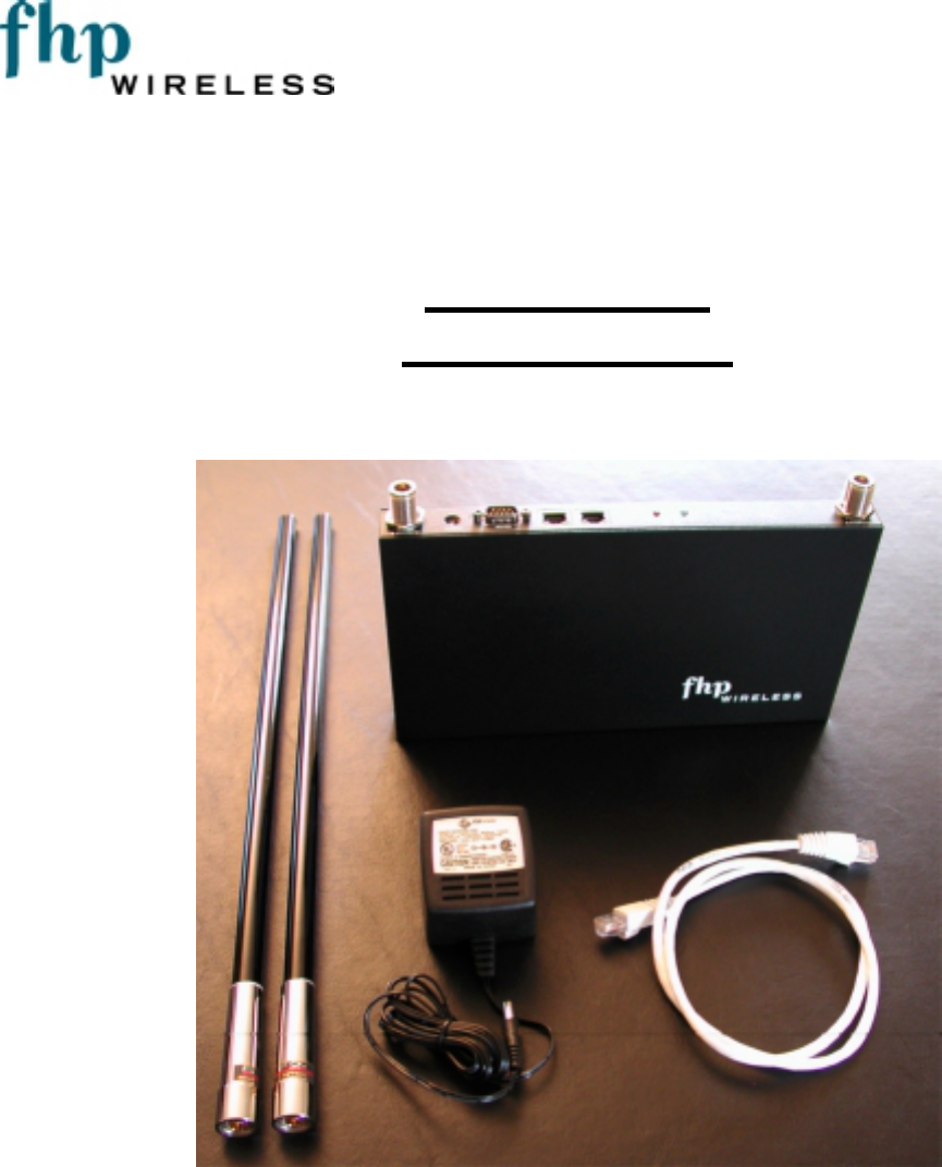
FHP SmartPointTM
Professional
Installer Guide
FHP Wireless
1710 South Amphlett Boulevard, Suite 304
San Mateo, CA 94402

FHP SmartPoint Professional Installer Guide Draft Version 1.6: May 10, 2002
© 2002, FHP Wireless, Inc. 2
Table of Contents
NOTICE TO USERS AND OPERATORS: 3
Introduction 4
FHP SmartPoint vs. Typical Access Point 4
Gateways and Nodes 5
Security Considerations on 802.11b Networks 6
Selecting Locations for the Gateway & Nodes 6
Installation Guidelines 6
Basic Guidelines 7
Antenna Options 7
Site Surveys 7
SmartPoint RF Planning Guidelines: 8
Wall Mounting Instructions 9
Physically Connecting the Gateways & Nodes 11
Initial Software Configuration – Setting up a Gateway 12
SmartPoint IP Addressing: 12
Connecting to the SmartPoint: 12
Configuring your PC to access the SmartPoint’s management address: 12
Accessing the web-based configuration utility: 15
Configuring Your Wireless Settings 17
Initial Software Configuration – Setting up a Node 19
Initial Software Configuration – Client Device Settings 19
How IP Addressing Works on a Client Device 19
Safety Information for the FHP SmartPoint 20

FHP SmartPoint Professional Installer Guide Draft Version 1.6: May 10, 2002
© 2002, FHP Wireless, Inc. 3
NOTICE TO USERS AND OPERATORS:
This device complies with Part 15 rules. Operation is subject to the following two conditions:
1. This device may not cause harmful interference, and
2. This device must accept any interference received, including interference that may cause undesired
operation.
This equipment has been tested and found to comply with the limits of a Class B digital device, pursuant to Part
15 of the FCC Rules. These limits are designed to provide reasonable protection against harmful interference
when the equipment is operated in a residential environment. This equipment generates, uses, and radiates radio
frequency energy, and if not installed and used in accordance with the instructions, may cause harmful
interference. However, there is no guarantee that interference will not occur. If this equipment does cause
interference to radio or television reception, which can be determined by turning the equipment off and on, the
user is encouraged to correct the interference by one of the following measures:
• Reorient or relocate the receiving antenna.
• Increase separation between the equipment and receiver.
• Connect the equipment to an outlet on a circuit different from which the receiver is connected.
• Consult the dealer or an experienced radio/TV technician.
Caution The Part 15 radio device operates on a non-interference basis with other
devices operating at this frequency. Any changes or modification to said product not
expressly approved by FHP Wireless could void the user's authority to operate this
device.
FHP SmartPoint Professional Installer Guide Draft Version 1.6: May 10, 2002
© 2002, FHP Wireless, Inc. 4
Introduction
This guide is intended for a trained technical professional. The guide provides the installation
instructions and procedures for the SmartPoint product. Operation and network configurations for the
SmartPoint product are detailed in the SmartPoint Operators Manual.
These installation instructions apply to the following SmartPoint model numbers:
WMR530-01-00B-C-N-02 1.5dBi omni pattern antenna configuration
WMR530-01-00B-C-N-08 7.4dBi omni pattern antenna configuration
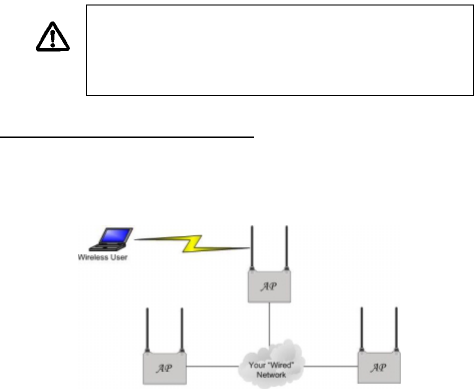
FHP SmartPoint vs. Typical Access Point
Typical 802.11b access points must be “hardwired” to your internal network. To install an access
point, you would connect the access point’s Ethernet port to a hub or switch port on your internal
network. Each access point would act as an extension to your wired network by serving as a
repeater or bridge, connecting clients to your internal network. The following diagram is an example
of a standard access point network.
FHP’s SmartPoints function very differently than traditional, “wired” access points. For a small or
large FHP network installation, only a small number of SmartPoints need to be “hardwired” to your
internal network. In fact, only one SmartPoint needs to be connected to your internal network to
provide connectivity for wireless users. For many wireless networks, one wired SmartPoint (gateway)
is all that is needed. For added redundancy and additional bandwidth for larger wireless networks,
additional gateways can be added as necessary.
NOTE:
The FHP SmartPoint must be installed by a trained professional, Value
Added Reseller or Systems Integrator familiar with RF cell planning issues
and the regulatory limits defined by the FCC RF Exposure, specifically those
outlined in sections 1.1307.
FHP SmartPoint Professional Installer Guide Draft Version 1.6: May 10, 2002
© 2002, FHP Wireless, Inc. 5
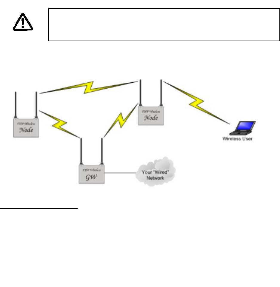
Non-wired SmartPoints (nodes) function independently to form large, routed wireless networks. All
you need is power for the SmartPoints, and you can expand your wireless network by adding nodes
to the network. In this way, you can truly build large, routed wireless networks covering areas
traditionally hard to reach due to the hardwire limitation of the Ethernet connections, the typical
access point wire-side interface1.
SmartPoints auto-configure themselves to form clusters around each wired gateway. No user
intervention is required and no knowledge of routing protocols is necessary to configure your network.
Each device needs some basic configuration information (ESSID, WEP Key, etc), but other than that,
your wireless network will configure itself and perform all routing functions in the background, without
need for user intervention. Even the IP addressing on the wireless network is auto-configured and
pre-set at the factory. This enables true “plug-and-play” configuration of your FHP SmartPoint
wireless router.
The below diagram shows an FHP SmartPoint network and how it differs from a traditional
installation.
Gateways and Nodes
Every SmartPoint can either be configured as a gateway or a node via the FHP Configurator’s web
interface. Every FHP wireless network needs at least one gateway. So, if you have purchased a
single unit, configure it as a gateway. If you have purchased more than one SmartPoint, then
configure at least one as a gateway. The rest, you can configure as nodes on your wireless network.
1 10/100Base-T Ethernet using Cat5 cabling has a 100 meter distance limitation.
NOTE:
Refer to the SmartPoint Operators Manual for information on how to
configure the SmartPoint product.
FHP SmartPoint Professional Installer Guide Draft Version 1.6: May 10, 2002
© 2002, FHP Wireless, Inc. 6
Security Considerations on 802.11b Networks
One of the most important considerations in building your wireless network is making sure that your
internal data is secure. Inherent to 802.11b are some security features to keep your data safe.
Unfortunately, most of these features are fairly easy to circumvent, potentially compromising your
internal network. This is a problem that the entire industry is working on, and future revisions of
wireless standards are expected to enhance security. With some proper planning, most of these
inefficiencies can be avoided. FHP recommends that the SmartPoint gateway be installed in front of
your company firewall (on the Internet segment) or on the DMZ segment of your company firewall.
This will ensure that users of your wireless network are only allowed out to the Internet and can not
gain access to your internal resources. Should your wireless network become compromised in any
way, all that would be available to attackers would be free access to the Internet.
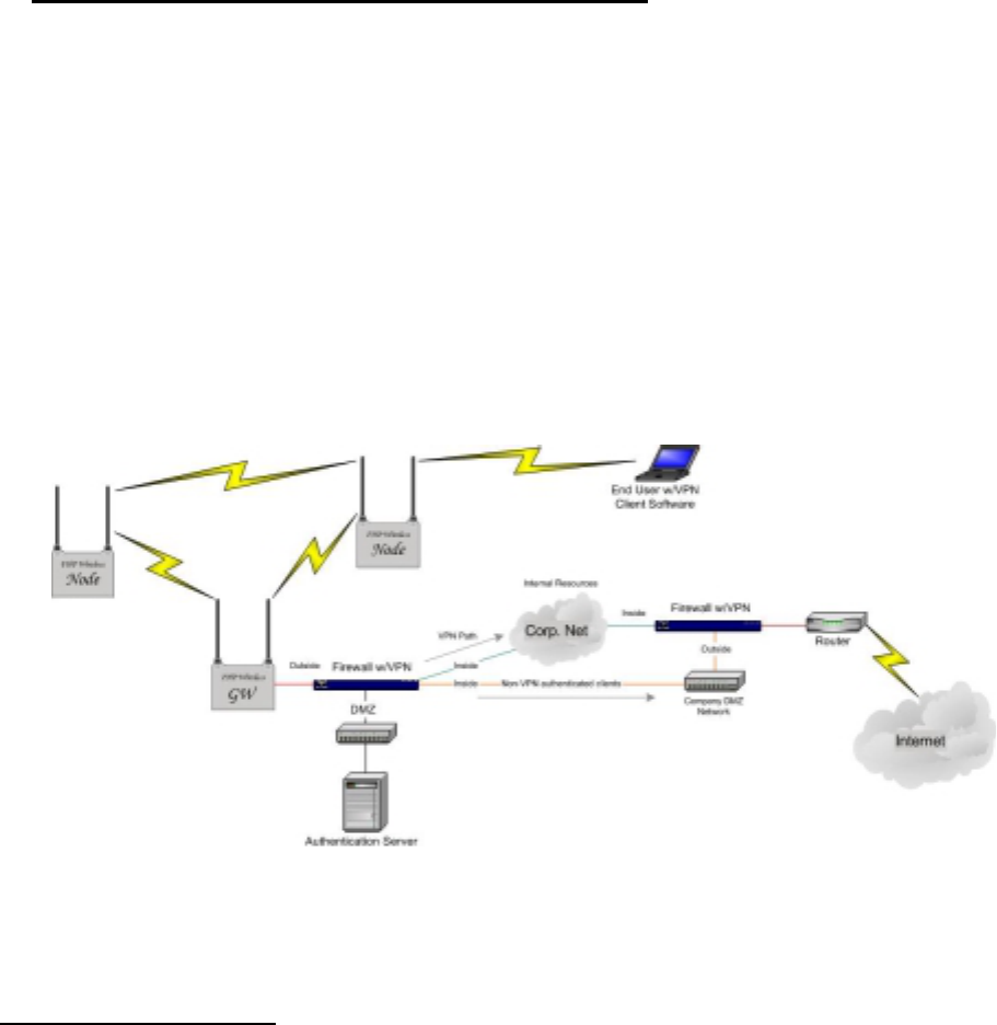
VPNs and other authentication methods provide enhanced security for your wireless network. The
following diagram shows a wireless network configured to allow users access to internal company
resources through a VPN and to allow non-authenticated users access to the Internet by default.
This configuration would allow visitors and clients access to the Internet while simultaneously
protecting internal resources.
Selecting Locations for the Gateway & Nodes
Installation Guidelines
This section describes things to keep in mind when installing your SmartPoint. Sections
include:
• Basic Guidelines
• Antenna Options
• Site Surveys

FHP SmartPoint Professional Installer Guide Draft Version 1.6: May 10, 2002
© 2002, FHP Wireless, Inc. 7
• SmartPoint to SmartPoint Range
Basic Guidelines
Because the SmartPoint is a radio device, it is susceptible to common causes of interference
that can reduce throughput and range. Follow these basic guidelines to ensure the best
possible performance:
• Install the SmartPoint antenna in an area where trees, buildings, or large steel
structures such as shelving units, bookcases, and filing cabinets do not obstruct radio
signals to and from the antenna. The antennas must be located for direct line-of-sight
operation.
• Minimize the distance between the SmartPoint and the antenna to reduce signal loss.
• Install the SmartPoint away from microwave ovens or other devices operating in the
2.4 GHz frequency range. Microwave ovens operate on the same frequency as the
SmartPoint and can cause signal interference.
Antenna Options
The SmartPoint supports external antennas with omni-directional or directional capabilities.
Omni-directional antennas are best for systems requiring a signal distribution in more than
one direction. High-gain directional antennas are best suited for covering longer distances in
a fixed direction.
Site Surveys
Because of differences in component configuration, placement, and physical environment,
every network application is a unique installation. Before installing multiple SmartPoints,
you should perform a site survey to determine the optimum utilization of networking
components and to maximize range, coverage, and network performance.
Consider the following operating and environmental conditions when performing a site
survey:
• Data rates - Sensitivity and range are inversely proportional to data bit rates. The
maximum radio range is achieved at the lowest workable data rate. A decrease in
receiver threshold sensitivity occurs as the radio data increases.
• Antenna type and placement - Proper antenna configuration is a critical factor in
maximizing radio range. As a general rule, range increases in proportion to antenna
height and gain.
• Physical environment - Clear or open areas provide better radio range than closed or
filled areas. Also, the less cluttered the work environment, the greater the range.

FHP SmartPoint Professional Installer Guide Draft Version 1.6: May 10, 2002
© 2002, FHP Wireless, Inc. 8
• Obstructions - A physical obstruction such as a building or a tree can block or hinder
communication between SmartPoints. Avoid locating the antennas in a location
where there is an obstruction between the sending and receiving antennas.
• Building materials - Radio penetration is greatly influenced by the building material
used in construction. For example, drywall construction allows greater range than
concrete blocks. Metal or steel construction is a barrier to radio signals.
SmartPoint to SmartPoint Range
The SmartPoint wireless network depends on performing multi-hop data transfers across
numerous SmartPoints in order to provide connectivity to a SmartPoint Gateway.
The RF planning implication to this is that SmartPoint Gateways and SmartPoint Nodes need
to be distanced from each other in such a way that one device may be able to communicate
with other SmartPoint devices over the RF wireless interface. . On the other hand, clustering
too many SmartPoints together within a small geographic area may create a situation where
the SmartPoint devices generate excessive interference with each other, in which case,
throughput performance of the network may be impaired.
A single SmartPoint device should have a partial overlapping coverage area with one or more
SmartPoint devices. As a general rule of thumb, placing a Smartpoint such that it has partial
overlapping coverage area with two other SmartPoints will provide adequate network
redundancy while mitigating interference
SmartPoint RF Planning Guidelines:
SmartPoints will work in almost any environment and wireless network topology due to the
adaptive self-healing nature of FHP’s proprietary wireless meshed routing technology
embedded in each SmartPoint. To maximize coverage range, however, locate them in
wireless-friendly areas. Try not to place them in areas that could block or interfere with
transmission. 802.11b devices transmit in the 2.4Ghz frequency spectrum, which is shared
by devices such as microwave ovens, portable phones, intercom systems and wireless alarm
systems. Place each SmartPoint in a location at least 15 to 20 feet from any other transmitter
to prevent the possibility of interference. Locating your SmartPoints high on a wall or
hanging from a ceiling is a good start. This allows transmission over the entire environment
or office space with minimal blocking objects. If you are trying to cover an outdoor area
from inside a building, place SmartPoints on or in-front of non-metallic coated windows or
close to the outside walls of the building. Using some common sense planning to place the
SmartPoints will greatly increase your coverage area.
FHP SmartPoint Professional Installer Guide Draft Version 1.6: May 10, 2002
© 2002, FHP Wireless, Inc. 9
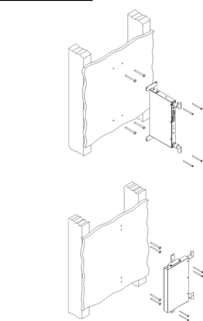
Wall Mounting Instructions
The SmartPoint has two wall mounting options illustrated below:
Wall Mounting Option #1
Wall Mounting Option #2
Provided with each SmartPoint:
4 - 1-inch drywall screws
FHP SmartPoint Professional Installer Guide Draft Version 1.6: May 10, 2002
© 2002, FHP Wireless, Inc. 10
4 – 1-inch drywall anchors
2 – Right Angle Mounting Brackets
1 – SmartPoint device
2 – optioned antennas (if any)
1 – 0.5ml capsule of Loctit Threadlock 242 (used to bond antenna connectors to unit)
You will need the following items to complete the installation of the SmartPoint.
1- Philips head screw driver
1 – Drill with 3/16 inch diameter drill bit
1 – Stud Finder device
1 - Non-switched, 110v/ 15 amp, duplex power outlet within 5 feet of where
the SmartPoint will be mounted.
A wood or plaster board wall with adequate clearance to mount the
SmartPoint.
Wall mounting the SmartPoint:
1. Decide upon the mounting orientation of the SmartPoint and fasten mounting
brackets accordingly.
2. Locate two studs on the wall; using either a “stud finder”. The SmartPoint should be
mounted midway between the two studs.
3. Drill 4 holes in to the wall to accommodate the mounting brackets.
4. Push the 4 wall anchors in to the 4 drill holes just made in the plaster board.
5. Holding the unit in place such that the bracket holes align with the wall anchors; screw the
unit to the wall.
NOTE:
In order to comply with FCC RF exposure limits, SmartPoint dipole
antennas should be located at a minimum distance of 7.9 inches (20 cm)
or more from the body of all persons.
NOTE:
Install the SmartPoint in an area where large steel structures such as
shelving units, bookcases, and filing cabinets do not obstruct radio
signals to and from the device or it’s antennas.
FHP SmartPoint Professional Installer Guide Draft Version 1.6: May 10, 2002
© 2002, FHP Wireless, Inc. 11
6. Perform a trail installation of the antennas or antenna cables, depending upon the installation.
7. Once the installer is satisfied with the trial placement of the antennas, and antenna cables,
remove antenna connections from the SmartPoint device and apply two drops of Loctite
ThreadLocker 242 (supplied with SmartPoint) to antenna connector thread, then install the
antenna or antenna cables.
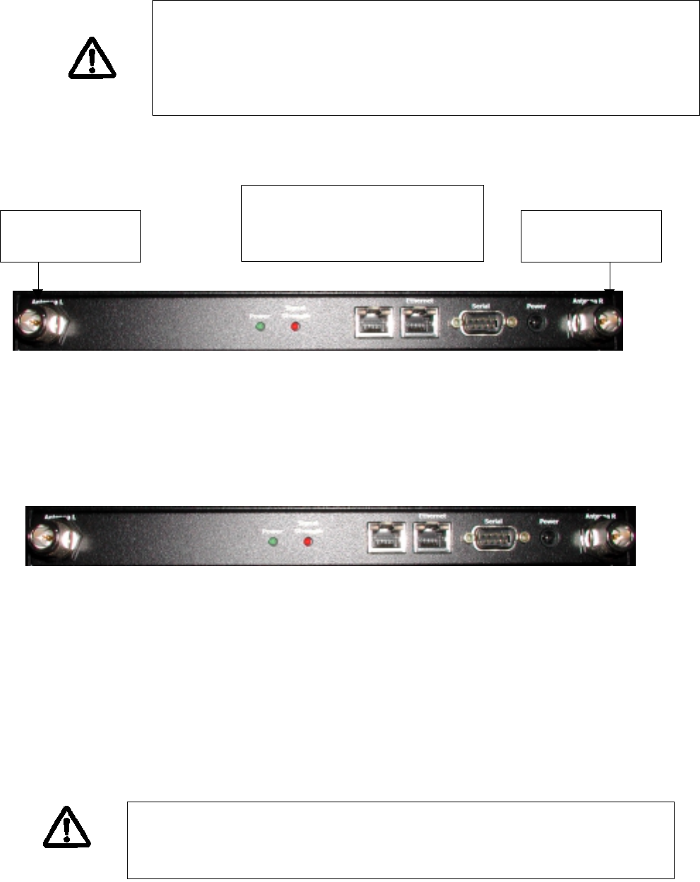
Physically Connecting the Gateways & Nodes
Connecting SmartPoints to your network is a fairly straightforward process. You will find the following
physical connectors on each SmartPoint: two antenna connectors (Left and Right), two 10/100Mbps
Ethernet connectors, a DB-9 serial port and a power connector.
To prepare each SmartPoint for use, do the following:
1. Connect the supplied AC/DC adapter to the SmartPoint, and plug the power adapter into a
standard 120V AC power outlet. Wait 2 minutes for the SmartPoint to boot.
Attach a Category 5 shielded twisted pair patch cable to the Ethernet port labeled “Ethernet” on the
SmartPoint, and then connect it directly into your PC or laptop or to your internal network. See the
above Security Considerations section on where to connect the SmartPoint to your internal network.
The serial port is not used by the end-user and is for factory use only. The serial port is used at the
factory to configure settings and software during the initial configuration of the SmartPoint. It will not
be necessary to use this port for configuration.
NOTE:
Antennas and antenna cables must be bonded to the SmartPoint unit to
avoid modification or tampering with the antenna configuration after
installation. Apply 2 drops of Loctite ThreadLocker 242 before the final
installation of the antennas or antenna cables.
Apply 2 drops of
Loctite here
Apply 2 drops of
Loctite here
Before securing the antennas
or antenna cables, apply
LocTite
NOTE:
The DB-9 connector marked “Serial Port” is for Factory Use Only. It is
not intended to be used by the customer or service personal.
FHP SmartPoint Professional Installer Guide Draft Version 1.6: May 10, 2002
© 2002, FHP Wireless, Inc. 12
Initial Software Configuration – Setting up a Gateway
Important Note:
To successfully install a SmartPoint gateway, you will need to have the following information before
proceeding:
1. An IP address for your SmartPoint gateway’s Ethernet interface
2. The subnet mask for the above IP address
3. The default gateway that the SmartPoint will use
4. IP addresses for two DNS servers on your network or your ISP’s network
SmartPoint IP Addressing:
At the factory, each SmartPoint is set with both a “hard-coded” IP address for use on the wireless
network and a management IP address for use in the initial configuration of the SmartPoint. Each
SmartPoint has its “hard-coded” IP address labeled on the bottom of the unit. The SmartPoint
management address on each unit is 192.168.168.168. These two addresses represent the initial
configuration of the wireless network address and the Ethernet network address, respectively.
Connecting to the SmartPoint:
To initially configure a SmartPoint, you will use a web browser to contact the SmartPoint on its
management IP address while connected to your internal network. Alternatively, if you would rather
not configure the device on your internal network, you may use a crossover Ethernet cable connected
between your PC’s Ethernet port and the Ethernet port of the SmartPoint. In either case, your PC will
need to be configured to the same subnet as the SmartPoint’s management address to complete the
initial configuration. As a result, you will need to temporarily change the TCP/IP settings of your
computer.
Configuring your PC to access the SmartPoint’s management address:
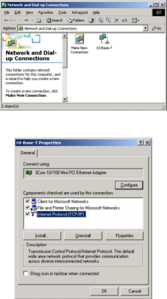
To find your PC’s Ethernet interface configuration information, right click on Network Neighborhood,
and go to properties. Alternatively, use the control panel and double click on the network icon in the
control panel folder. Look for your local area connection or Ethernet network icon as shown below.
(This guide has been written for Windows 2000. If you are using another operating system, please
consult your operating system manual.)
NOTE:
Ethernet cable used on this device should be a shielded Cat5 twisted pair
type.
FHP SmartPoint Professional Installer Guide Draft Version 1.6: May 10, 2002
© 2002, FHP Wireless, Inc. 13
Right click on the icon representing your Ethernet interface on your computer; in this case, the icon is
labeled, “10-Base-T”.
Select the Internet Protocol menu item shown above, and click on Properties.
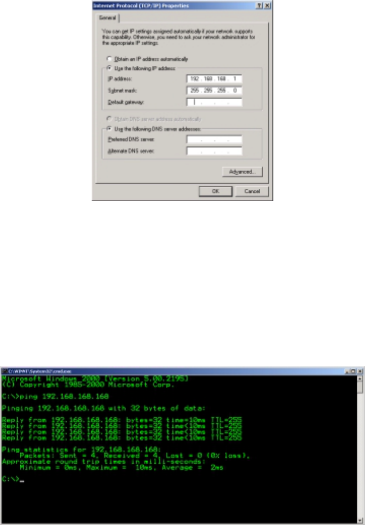
Do not change the settings in the Internet Protocol properties window until you write down your
current configuration. Many end-user machines are set to obtain an IP address automatically. If that
is the case, then when you initially bring up this window, you will have no configuration information. If
your machine has information already filled in, write down the settings in each field so that you can
change them back when you are done with the initial configuration of the SmartPoint.
Click on “Use the following IP address,” and enter 192.168.168.1 with a subnet mask of
“255.255.255.0”. It is not necessary to enter a default gateway or DNS server information for this
configuration.
FHP SmartPoint Professional Installer Guide Draft Version 1.6: May 10, 2002
© 2002, FHP Wireless, Inc. 14
Once you are done configuring your PC, click on the OK box. After a few seconds, your PC will
accept the new settings. In some cases, you may be asked to reboot your computer to complete the
settings. If this is the case, reboot the computer.
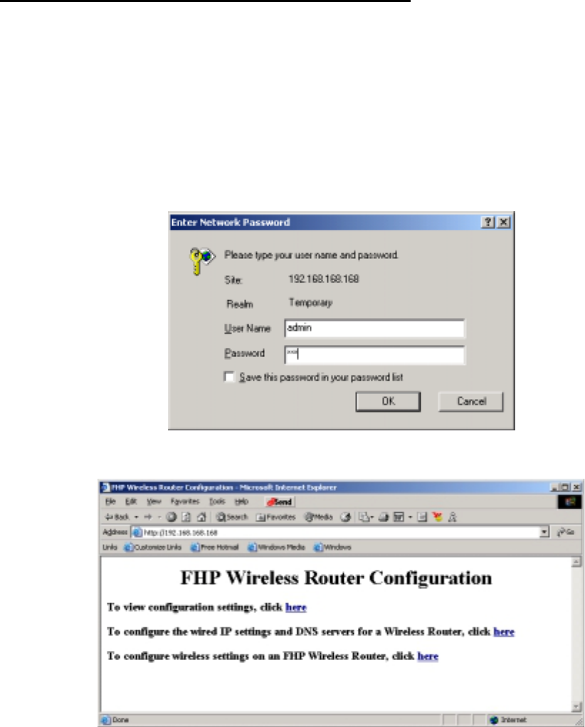
At this point, your PC and your SmartPoint should be connected to the same TCP/IP subnet. Before
you bring up a web browser to contact the SmartPoint, verify connectivity to the SmartPoint by
running a ping test. Launch a command window by clicking on the “Start” button in the lower left-
hand corner of your desktop. Choose “Run”, and type “cmd” or “command” and click OK. A
command window will start up. Type in the following to check connectivity to the SmartPoint:
Ping the SmartPoint’s management IP address of 192.168.168.168.
You should see a reply from the SmartPoint on the above IP address. If you see something like
“request timed out”, then review the above steps and make sure the network setting are configured
correctly on your PC. Once you have connectivity to the SmartPoint, continue to the next step.
FHP SmartPoint Professional Installer Guide Draft Version 1.6: May 10, 2002
© 2002, FHP Wireless, Inc. 15
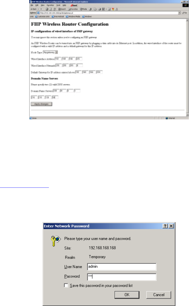
Accessing the web-based configuration utility:
At this point, you are ready to access the configuration utility on the SmartPoint from your web
browser. Launch a web browser (Explorer or Netscape) on your PC and type in the SmartPoint’s
management IP address in the browser’s URL window. (http://192.168.168.168)
(Please note that on the current pre-release units, the CGI-based dynamic web pages described
below may take up to one minute to be processed on the SmartPoint’s web server.)
After a few seconds you will be prompted to log into the SmartPoint. The username is admin and the
password is fhp.
Username: admin
Password: fhp
Once properly logged in, you will see the following screen:
Since you are configuring the first device on your network, a SmartPoint gateway, select the second
choice to configure the wired IP settings for the gateway.
FHP SmartPoint Professional Installer Guide Draft Version 1.6: May 10, 2002
© 2002, FHP Wireless, Inc. 16
Under Node Type, select FHPGateway and enter the rest of the network information for the gateway.
Your network administrator has access to this information concerning IP address, Subnet Mask,
Gateway, and both DNS servers. Please do not enter a single DNS server; you must provide two
DNS servers for the configuration to properly update.
Once you have entered your settings, click on the Apply Changes button. At the bottom of the web
page, you will see a confirmation, “Committed Changes”. You may click on the link directing you to
view your changes. At this point, reboot the SmartPoint: un-plug the power from the SmartPoint, wait
about 30 seconds, and then reconnect power to the SmartPoint. Wait about two minutes for the
SmartPoint to reboot; then, point your browser to the management IP address of the gateway
(http://192.168.168.168) to reconnect to the gateway.
Log back into the SmartPoint if necessary:
Username: admin
Password: fhp
FHP SmartPoint Professional Installer Guide Draft Version 1.6: May 10, 2002
© 2002, FHP Wireless, Inc. 17
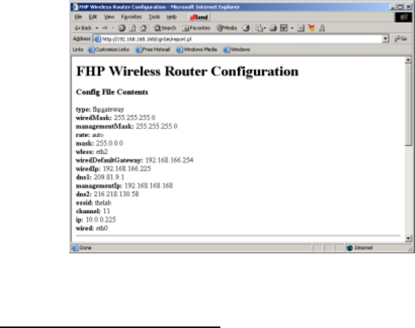
Now, you can verify your configuration settings by selecting the first choice in the menu.
Once you have looked at your settings and are satisfied with the changes on the wired interface, use
your browser’s back button, and select the third choice in the menu, “Configure wireless settings”.
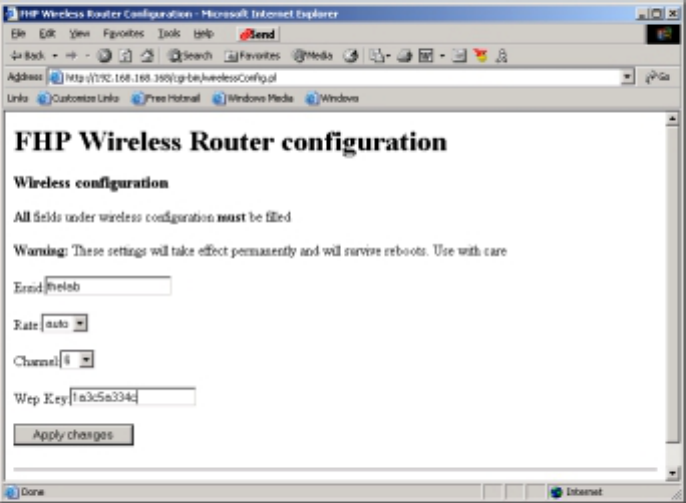
Configuring Your Wireless Settings
To properly set up your wireless network, there are a few settings that must match on all SmartPoints.
Each SmartPoint that you configure for your network should have the exact wireless configuration as
every other SmartPoint on your network. If for some reason the information is different, the
SmartPoints with different information will not be able to talk to the rest of your network. In addition,
client devices will not be able to use the SmartPoints with different wireless network information.
There are four settings that you need to configure: ESSID, Wireless Client Rate, Channel, and a
WEP Key.
ESSID stands for Extended Service Set Identifier. It is a password that you use so that all of your
SmartPoints and client devices can talk together in the same “group”. “Password” is used loosely
here, since a wireless network analyzer can view an ESSID string. That is where your previous
security planning comes into play. An ESSID should be thought of as a group identifier. By entering
the same ESSID into every SmartPoint and every end-user client configuration, you place all of the
wireless devices into the same wireless network group.
The ESSID can be a word or a combination of letters and numbers. There can be no spaces in the
ESSID string. It’s not necessary to create hard to guess values here. Just something that makes
sense to you on your network and something that users will remember.
The Rate value allows you to “lock” clients to specific access speeds from 1Mbps to 11Mbps. FHP
recommends that you set this value to auto to allow clients to connect at any of the available rates.
Channel selection is the channel that each client will use to contact the SmartPoint. The most
commonly used channels are 1, 6 and 11; however, you may need to experiment to find the channels
with the least interference. It is hard to notice any difference between the channels available. A good
FHP SmartPoint Professional Installer Guide Draft Version 1.6: May 10, 2002
© 2002, FHP Wireless, Inc. 18
choice would be to start with channel 1 and set all the units to this channel. If you encounter
coverage problems or slow response times on the wireless network, you may need to change the
SmartPoints to another channel. If you have multiple wireless networks in the same building, it is a
good idea to find out what channel the other networks are using and put the SmartPoints on a
different channel. Like all of the other settings, make sure all of the SmartPoints on the same network
are set to the same channel.
WEP stands for Wireless Encryption Protocol. WEP encrypts each packet of data with a 40 bit or 128
bit encryption key, and then transmits it on the wireless network. The key must match on all
SmartPoints and all client devices. WEP can be turned off and is not necessary for the wireless
network to function; however, turning off WEP will greatly reduce your network security.
A WEP key is created in Hexadecimal, the digits 0 through 9 and the letters A through F. A hex byte
is a combination of the digits and letters in two character pairs. For example, 0A is a valid hex byte.
3B is also a valid hex byte. 4G, 5P, and 3T are invalid, since letters beyond the character “F” are
invalid. To create a 40 bit key, choose 5 hex bytes. To create a 128 bit key, choose 13 hex bytes.
An example of a valid 40 bit key is 0A3C4D5F4B. Any combination of numbers and letters as listed
above (0-9, A-F) will create a valid key. Once you create a key, use it to program all of your client
devices and SmartPoints on your wireless network. Be sure to record the WEP key that you have
created for your network. All client devices and SmartPoints will block the viewing of this key after it
has been set.
Once you have set all of the above values on the wireless configuration page in your web browser,
click on Apply changes. When the settings are accepted by the SmartPoint, you can use your
browser’s back button to check your changes on the configuration settings page. The WEP key will
not be shown on the settings page.
Congratulations! You have completed the configuration of your SmartPoint gateway. The following
information will help you configure your nodes and client devices to talk to your SmartPoint gateway.

FHP SmartPoint Professional Installer Guide Draft Version 1.6: May 10, 2002
© 2002, FHP Wireless, Inc. 19
Initial Software Configuration – Setting up a Node
Setting up a SmartPoint node requires fewer steps than setting up a gateway. Plug in the SmartPoint
to power. Connect an Ethernet cross-over cable between the Node and your PC. Point your browser
to the network management address: http://168.168.168. Log in using the username “admin” and
password “fhp”. Choose the third choice on the Configurator menu to change your wireless router
settings only. Input the same ESSID, Rate, Channel and WEP Key information that you entered for
the gateway.
SmartPoint nodes can also be configured by using a wireless client device that is running on the
SmartPoint gateway. The IP address given to a wireless client device by the gateway is on the same
subnet as the IP of the SmartPoint devices, which are set at the factory. With this configuration, it is
possible to configure the gateway, configure a client to work wirelessly with the gateway, and then set
up subsequent nodes with the client device. In this manner, it is only necessary to use the Ethernet
cross-over cable to configure the gateway. To configure the SmartPoint nodes wirelessly, use a web
browser and connect to the SmartPoints by accessing their wireless network IP addresses printed on
the back of each unit. (http://10.0.0.255, etc.) The configuration tool can then be used as described
above.
Initial Software Configuration – Client Device Settings
Client device settings must match those that you programmed into your SmartPoints. SmartPoints
operate in Ad Hoc, or Peer to Peer, mode rather than in Access Point mode. When you configure
your client devices, choose Ad Hoc or Peer to Peer mode.
A standard client configuration should contain the following:
Mode: Ad Hoc or Peer to Peer
ESSID: (Your ESSID created earlier)
Rate: Auto
Channel: Auto (Clients will find the proper channel by default)
WEP: (Your hex WEP Key created earlier)
A note on IP addressing: Make sure the client network adapter (Wireless Adapter) is set for DHCP
so that an IP address will automatically be assigned to a client device.
How IP Addressing Works on a Client Device
Once the above settings have been configured on your client device, the client will request an IP
address from the wireless network. The SmartPoint gateway runs the DHCP process and will give
the client device an IP address on the private class 10.0.0.0 network. In general, all SmartPoints on
the network will be in the 10.0.0.0 network, and client devices will run in the 10.0.1.0 network. Once
the SmartPoint gateway forwards an IP address to the client device, it will then be able to cross the
SmartPoint gateway and gain access to your internal network.

FHP SmartPoint Professional Installer Guide Draft Version 1.6: May 10, 2002
© 2002, FHP Wireless, Inc. 20
Safety Information for the FHP SmartPoint
The Federal Communications Commission (FCC) with its action in ET Docket 96-8 has
adopted a safety standard for human exposure to RF electromagnetic energy emitted by FCC
certified equipment. The FHP SmartPoint series products meet the uncontrolled
environmental limits found in OET-65 and ANSI C95.1, 1991. Proper operation of this radio
according to the instructions found in this manual and the hardware and software guides on
the FHP Wireless SmartPoint will result in user exposure that is substantially below the FCC
recommended limits.
• Do not touch or move the antenna(s) while the unit is transmitting or receiving.
• Do not hold any component containing a radio such that the antenna is very close to
or touching any exposed parts of the body, especially the face or eyes, while
transmitting.
• Do not operate the radio or attempt to transmit data unless the antenna is connected;
otherwise, the radio may be damaged.
• Use in specific environments:
o Do not operate a portable transmitter near unshielded blasting caps or in an
explosive environment unless it is a type especially qualified for such use.
o The use of wireless devices in hazardous locations is limited to the
constraints posed by the safety directors of such environments.
o The use of wireless devices on airplanes is governed by the Federal Aviation
Administration (FAA).
o The use of wireless devices in hospitals is restricted to the limits set forth by
each hospital.
• Antenna use:
o In order to comply with FCC RF exposure limits, dipole antennas should be
located at a minimum distance of 7.9 inches (20 cm) or more from the body
of all persons.
o High-gain, wall-mount or mast-mount antennas are designed to be
professionally installed and should be located at a minimum distance of 12
inches (30 cm) or more from the body of all persons. Please contact your
professional installer, VAR, or antenna manufacturer for proper installation
requirements.
FHP SmartPoint Professional Installer Guide Draft Version 1.6: May 10, 2002
© 2002, FHP Wireless, Inc. 21
Appendix A: Service Instructions
The SmartPoint product has a real-time clock which is powered by a small lithium
rechargeable battery. If real-time clock should every fail, return the unit to FHP Wireless for
servicing.
CAUTION: Danger of explosion if battery is incorrectly
replaced. Replace only with the same or equivalent type
recommended by the manufacturer. Dispose of used
batteries according to the manufacturer's instructions.
CAUTION: No user serviceable parts inside. The
following is only intended to be performed by trained
service personnel.