ABB Genway Xiamen Electrical Equipment M2136 Mini video outdoor station User Manual Operating instruction
ABB Genway Xiamen Electrical Equipment Co., Ltd Mini video outdoor station Operating instruction
Contents
- 1. Operating instruction
- 2. Product manual
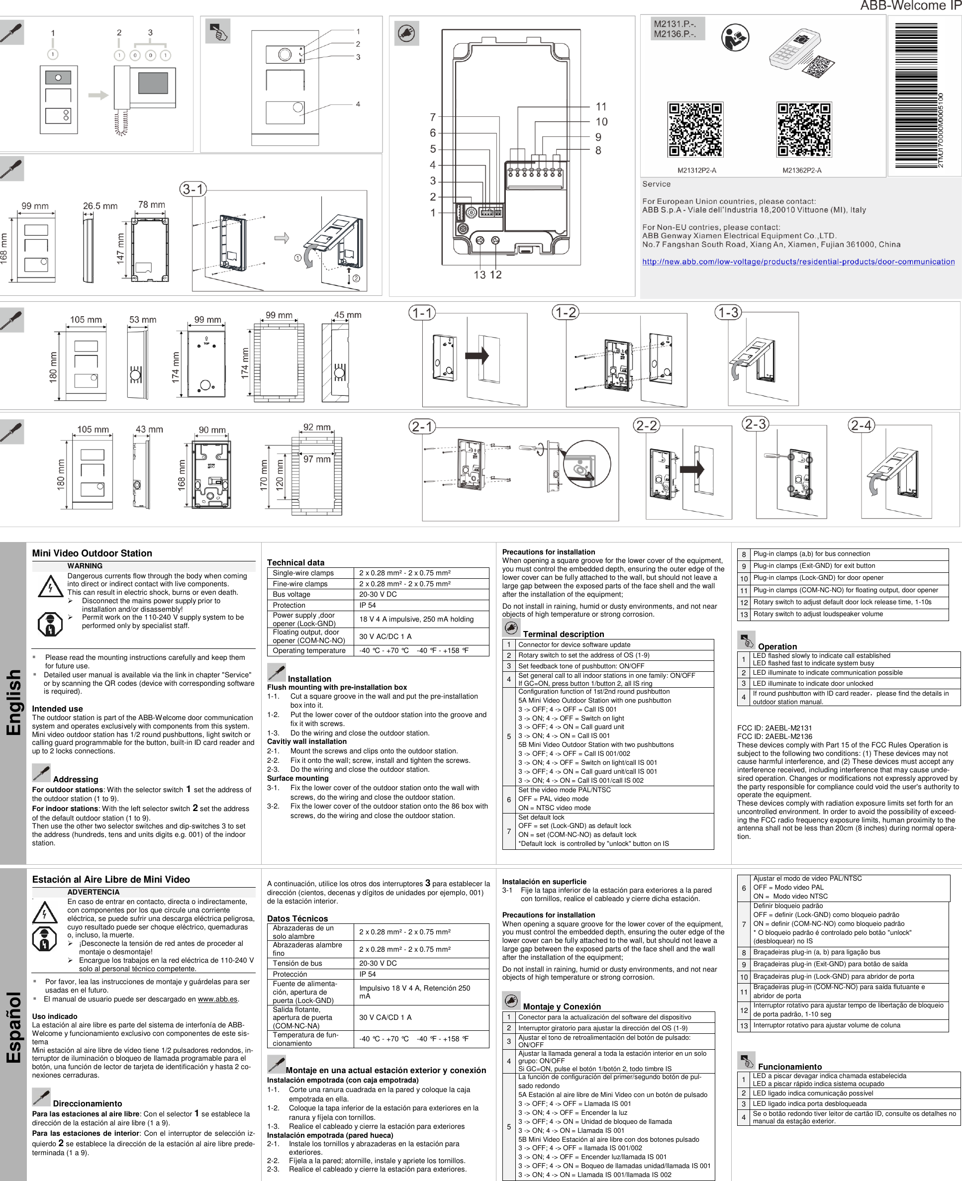
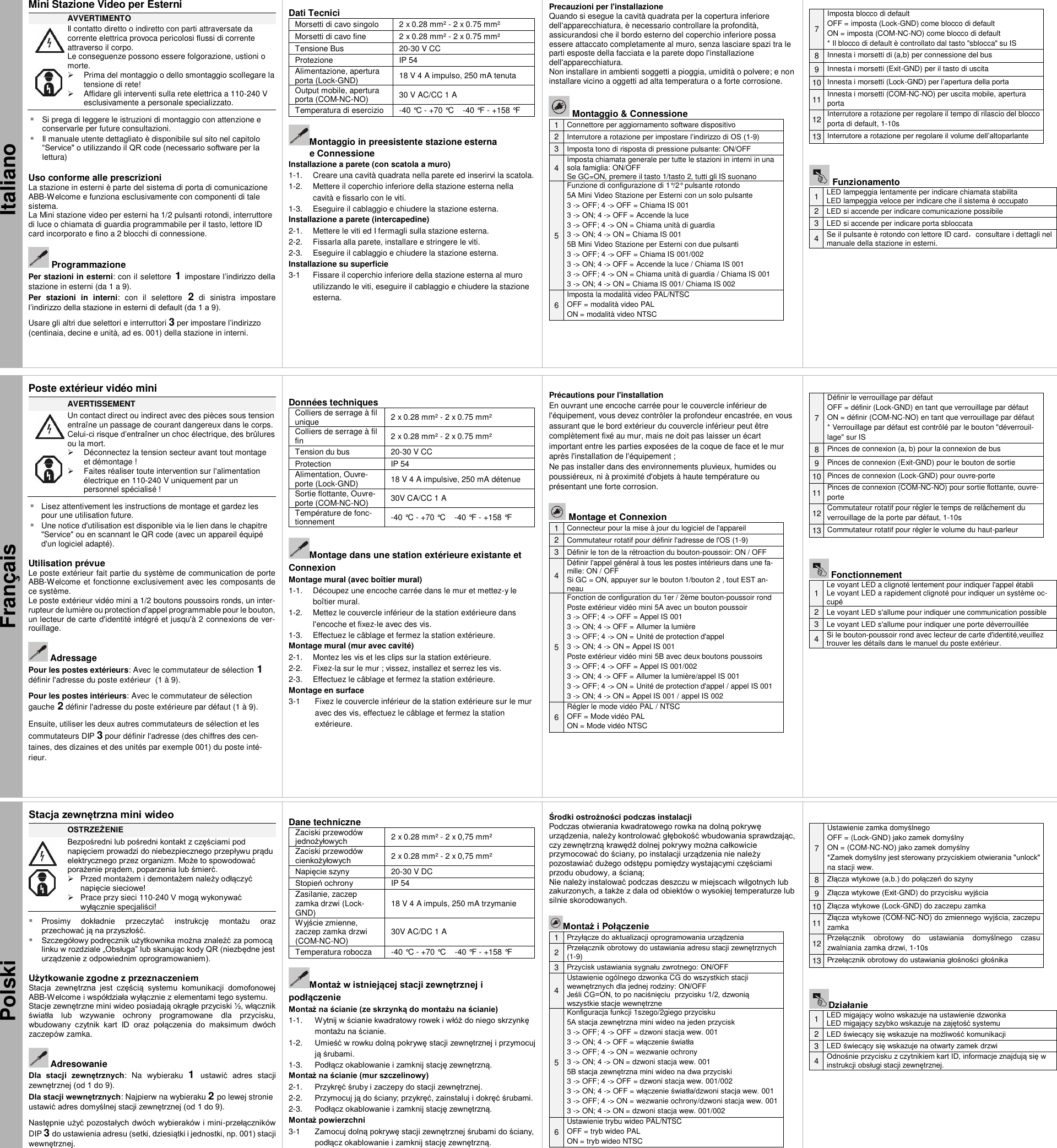
Operating instruction