ABB Genway Xiamen Electrical Equipment M2136 Mini video outdoor station User Manual Product manual
ABB Genway Xiamen Electrical Equipment Co., Ltd Mini video outdoor station Product manual
Contents
- 1. Operating instruction
- 2. Product manual
Product manual
VER:1.3 │ 20.06.2017
Operating Instructions
ABB-Welcome
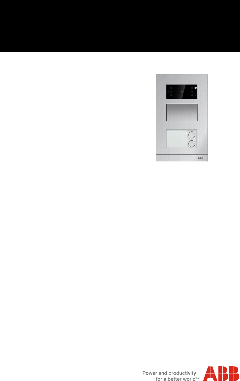
Mini video outdoor station
M2131.P.-.
M2136.P.-.

Table of contents
Operating Instructions VER:1.3
│2
Table of contents
1 Safety.................................................................................................................................................................. 3
2 Intended use ....................................................................................................................................................... 3
3 Environment ........................................................................................................................................................ 3
3.1 ABB devices ............................................................................................................................................ 3
3.2 Front overview ......................................................................................................................................... 4
3.3 Terminal description ................................................................................................................................. 5
3.4 Lock type and connection ......................................................................................................................... 7
4 Technical data ..................................................................................................................................................... 8
5 Mounting/Installation ............................................................................................................................................ 9
5.1 Requirement for the electrician ................................................................................................................. 9
5.2 Mounting ............................................................................................................................................... 10
5.2.1 Preparation .......................................................................................................................................... 10
5.2.2 Surface mounting ................................................................................................................................. 10
5.2.3 Flush mounting..................................................................................................................................... 11
5.2.4 Cavity wall installation .......................................................................................................................... 13
5.2.5 Dismantling .......................................................................................................................................... 15
5.2.6 Replace the nameplate ......................................................................................................................... 15
5.2.7 Installation situations ............................................................................................................................ 16
6 Commissioning .................................................................................................................................................. 17
6.1 Configure functions of the 1st/2nd pushbutton ........................................................................................ 17
6.2 Setting general call function ................................................................................................................... 19
7 Operation .......................................................................................................................................................... 20
7.1 Manage ID cards by mini outdoor station ................................................................................................ 20
Notice ........................................................................................................................................................................ 22
Safety
Operating Instructions VER:1.3
│3
1 Safety
Warning
Electric voltage!
Dangerous currents flow through the body when coming into direct or indirect
contact with live components.
This can result in electric shock, burns or even death.
– Disconnect the mains power supply prior to installation and/or disassembly!
– Permit work on the 110-240 V supply system to be performed only by
specialist staff!
2 Intended use
The outdoor station is an integral part of the ABB-Welcome door communication system and
operates exclusively with components from this system.
3 Environment
Consider the protection of the environment!
Used electric and electronic devices must not be disposed of with household
waste.
– The device contains valuable raw materials that can be recycled. Therefore,
dispose of the device at the appropriate collecting facility.
3.1 ABB devices
All packaging materials and devices from ABB bear the markings and test seals for proper
disposal. Always dispose of the packing materials and electric devices and their components via
an authorized collection facility or disposal company.
ABB products meet the legal requirements, in particular the laws governing electronic and
electrical devices and the REACH ordinance.
(EU-Directive 2002/96/EG WEEE and 2002/95/EG RoHS)
(EU-REACH ordinance and law for the implementation of the ordinance (EG) No.1907/2006)
Environment
Operating Instructions VER:1.3
│4
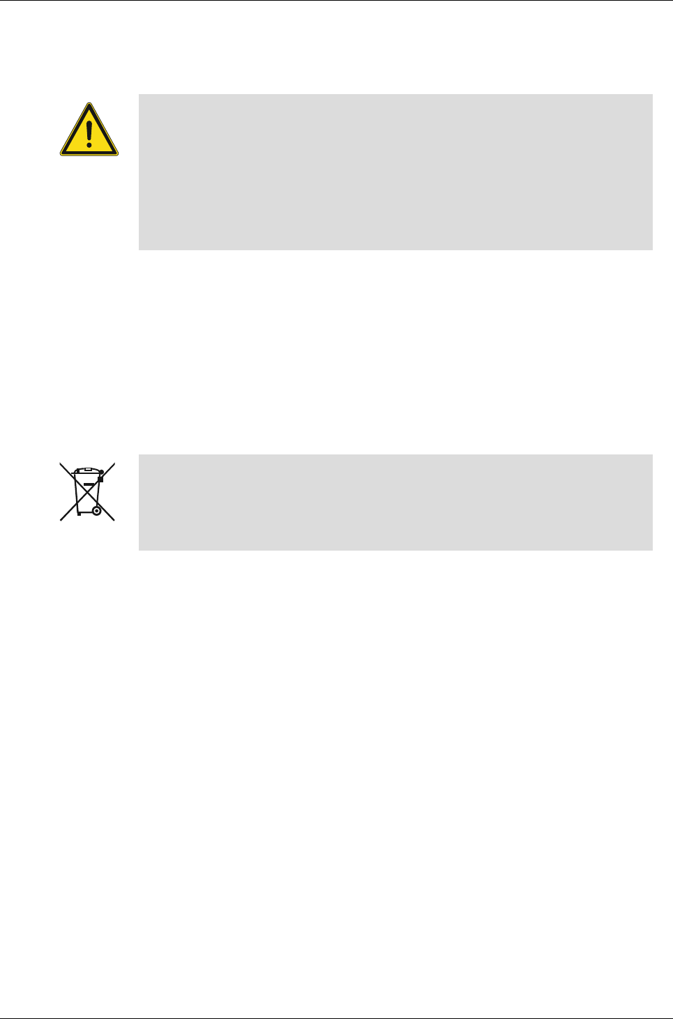
3.2 Front overview
Fig. 1
No
Function
1
Light sensor
2
Infrared LED
3
Indicator LED (ring, call and door open)
4
Speaker and microphone integration
5
Pushbutton
6
Nameplate
Tab.1
Environment
Operating Instructions VER:1.3
│5
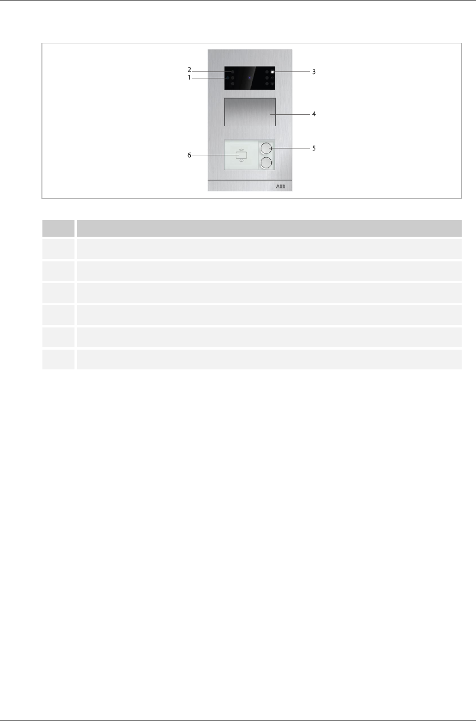
3.3 Terminal description
Fig. 2
No
Function
1
Connector for device software update
2
Rotary switch to set the address of outdoor station (1-9)
3
Set feedback tone of pushbutton ON/OFF
4
Set general call to all indoor stations in one family: ON/OFF
If GC=ON, press button 1/button 2, all IS ring
5
Configuration function of 1st/2nd round pushbutton
5A mini video outdoor station with one pushbutton
3 -> OFF; 4 -> OFF = Call IS 001
3 -> ON; 4 -> OFF = Switch on light
3 -> OFF; 4 -> ON = Call guard unit
3 -> ON; 4 -> ON = Call IS 001
5B mini video outdoor station with two pushbuttons
3 -> OFF; 4 -> OFF = Call IS 001/002
3 -> ON; 4 -> OFF = Switch on light/call IS 001
3 -> OFF; 4 -> ON = Call guard unit/call IS 001
3 -> ON; 4 -> ON = Call IS 001/call IS 002
1
2
3
4
5
6
7
8
9
10
11
1213

Environment
Operating Instructions VER:1.3
│6
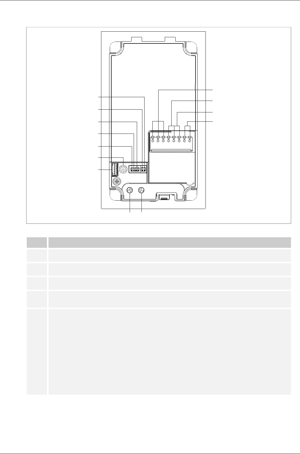
6
Set the video mode PAL/NTSC
OFF = PAL video mode
ON = NTSC video mode
7
Set default lock
OFF = set (Lock-GND) as default lock
ON = set (COM-NC-NO) as default lock
*Default lock is controlled by "unlock" button on IS
8
Plug-in clamps (a,b) for bus connection
9
Plug-in clamps (Exit-GND) for exit button
10
Plug-in clamps (Lock-GND) for door opener
11
Plug-in clamps (COM-NC-NO) for floating output, door opener
12
Rotary switch to adjust default door lock release time, 1-10s
13
Rotary switch to adjust loudspeaker volume
Tab.2
Environment
Operating Instructions VER:1.3
│7
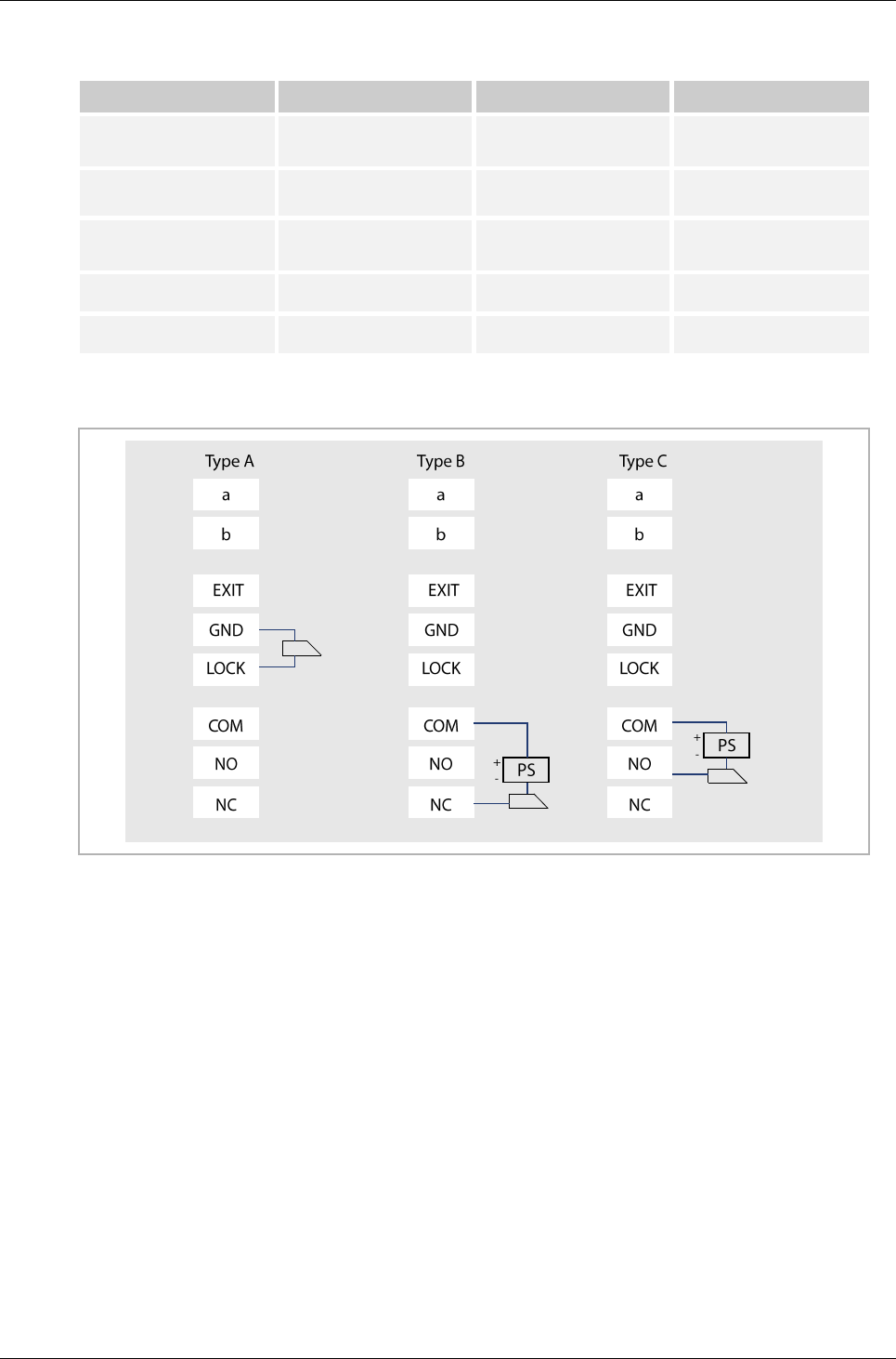
3.4 Lock type and connection
Lock type
Operation type
Voltage
Wiring type
Electrical strike lock,
12 V
Power on to open
12 VDC/AC
Type A
Type B
Electrical strike lock,
24 V
Power on to open
24 VDC/AC
Type B
Electrical rim lock, 12 V
Power on to open
12 VDC
Type A
Type B
Electrical mortise lock
Power off to open
12 VDC
Type C
Magnetic lock
Power off to open
12/24 V DC
Type C
Tab.3
Fig. 3

Technical data
Operating Instructions VER:1.3
│8
4 Technical data
Designation
Value
Operating temperature
-40 °C - +70 °C
Protection
IP 54
Power supply, door opener (Lock-GND)
18 V 4 A impulsive, 250 mA holding
Floating supply, door opener (COM-NC-NO)
30 V DC/AC 1A
Single-wire clamps
2 x 0.28 mm2 - 2 x 0.75 mm2
Fine-wire clamps
2 x 0.28 mm2 - 2 x 0.75 mm2
Bus voltage
20-30 V DC
Tab.4
Mounting/Installation
Operating Instructions VER:1.3
│9
5 Mounting/Installation
Warning
Electric voltage!
Dangerous currents flow through the body when coming into direct or indirect
contact with live components.
This can result in electric shock, burns or even death.
– Disconnect the mains power supply prior to installation and/or disassembly!
– Permit work on the 110-240 V supply system to be performed only by
specialist staff!
5.1 Requirement for the electrician
Warning
Electric voltage!
Install the device only if you have the necessary electrical engineering
knowledge and experience.
– Incorrect installation endangers your life and that of the user of the electrical
system.
– Incorrect installation can cause serious damage to property, e.g. due to fire.
The minimum necessary expert knowledge and requirements for the installation
are as follows:
– Apply the "five safety rules" (DIN VDE 0105, EN 50110):
1. Disconnect
2. Secure against being re-connected
3. Ensure there is no voltage
4. Connect to earth and short-circuit
5. Cover or barricade adjacent live parts.
– Use suitable personal protective clothing.
– Use only suitable tools and measuring devices.
– Check the type of supply network (TN system, IT system, TT system) to
secure the following power supply conditions (classic connection to ground,
protective grounding, necessary additional measures, etc.).
Mounting/Installation
Operating Instructions VER:1.3
│10
5.2 Mounting
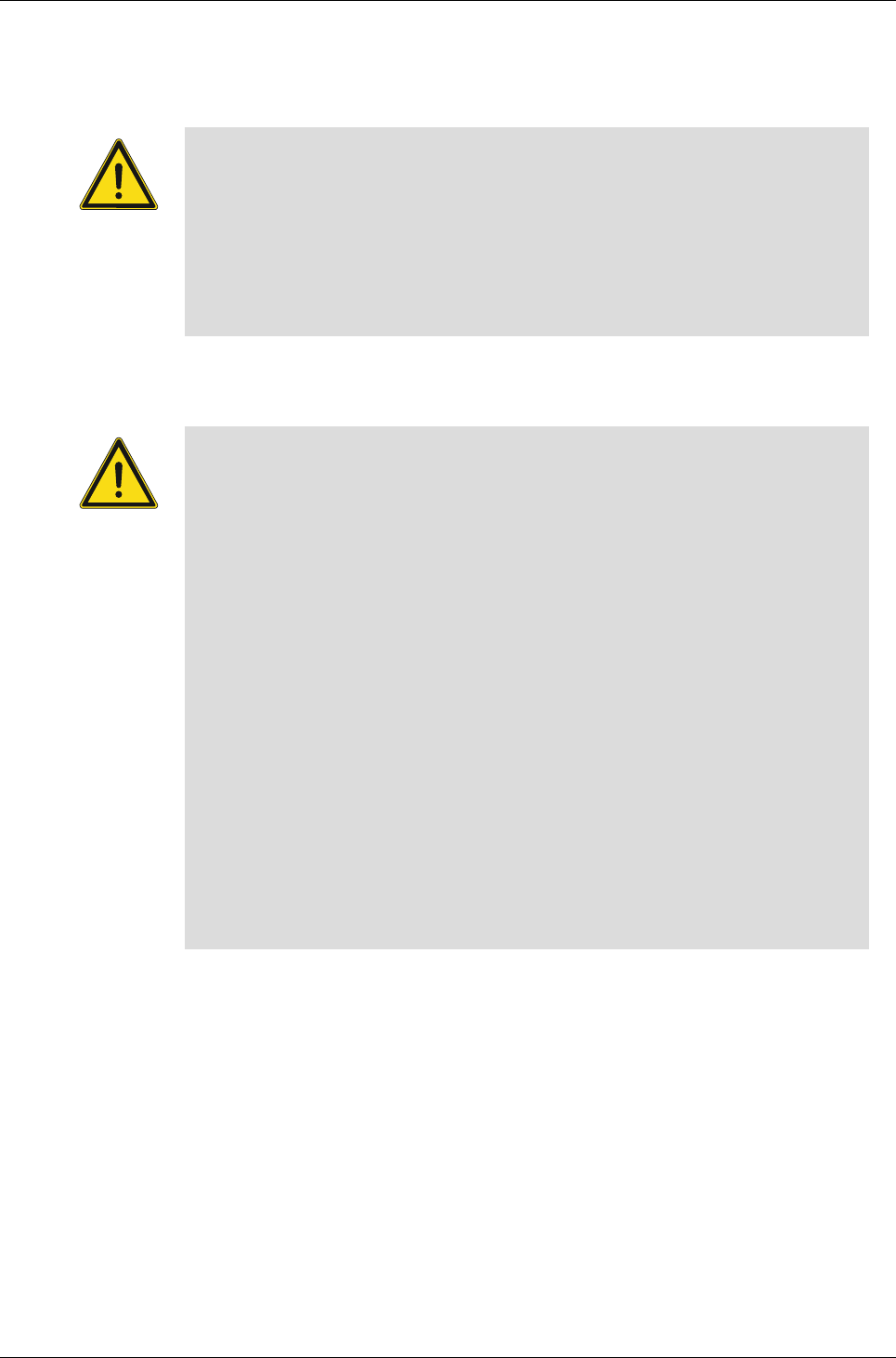
5.2.1 Preparation
Use gloves to protect yourself from being cut.
Fig. 4
5.2.2 Surface mounting
Fig. 5
99 mm 26.5 mm 78 mm
168 mm
147 mm
①
②
Mounting/Installation
Operating Instructions VER:1.3
│11
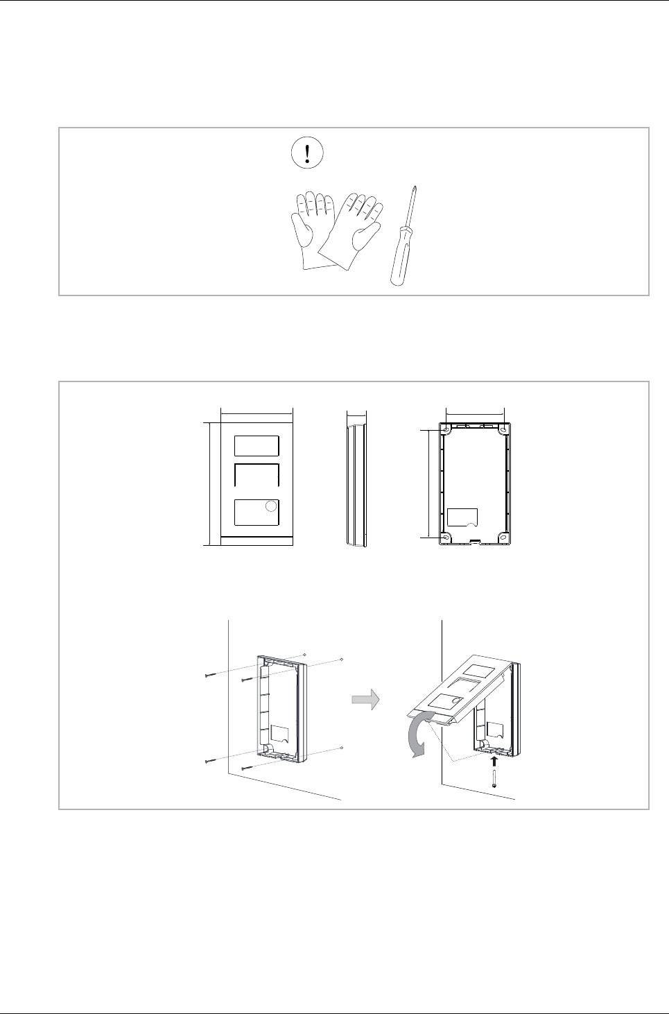
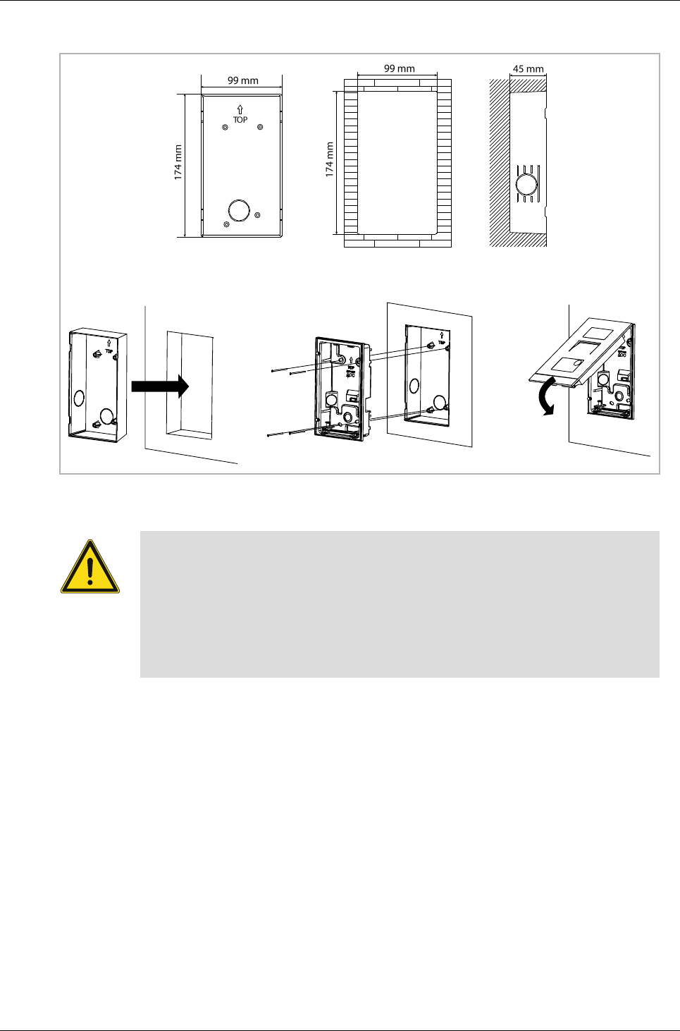
5.2.3 Flush mounting
Product dimension
Fig. 6
Mounting without pre-installation box
Fig. 7
Mounting/Installation
Operating Instructions VER:1.3
│12
Mounting with pre-installation box
Fig. 8
Precautions for installation
When opening a square groove for the lower cover of the equipment, you must
control the embedded depth, ensuring the outer edge of the lower cover can be
fully attached to the wall, but should not leave a large gap between the exposed
parts of the face shell and the wall after the installation of the equipment;
Do not install in raining, humid or dusty environments, and not near objects of
high temperature or strong corrosion.
Mounting/Installation
Operating Instructions VER:1.3
│13
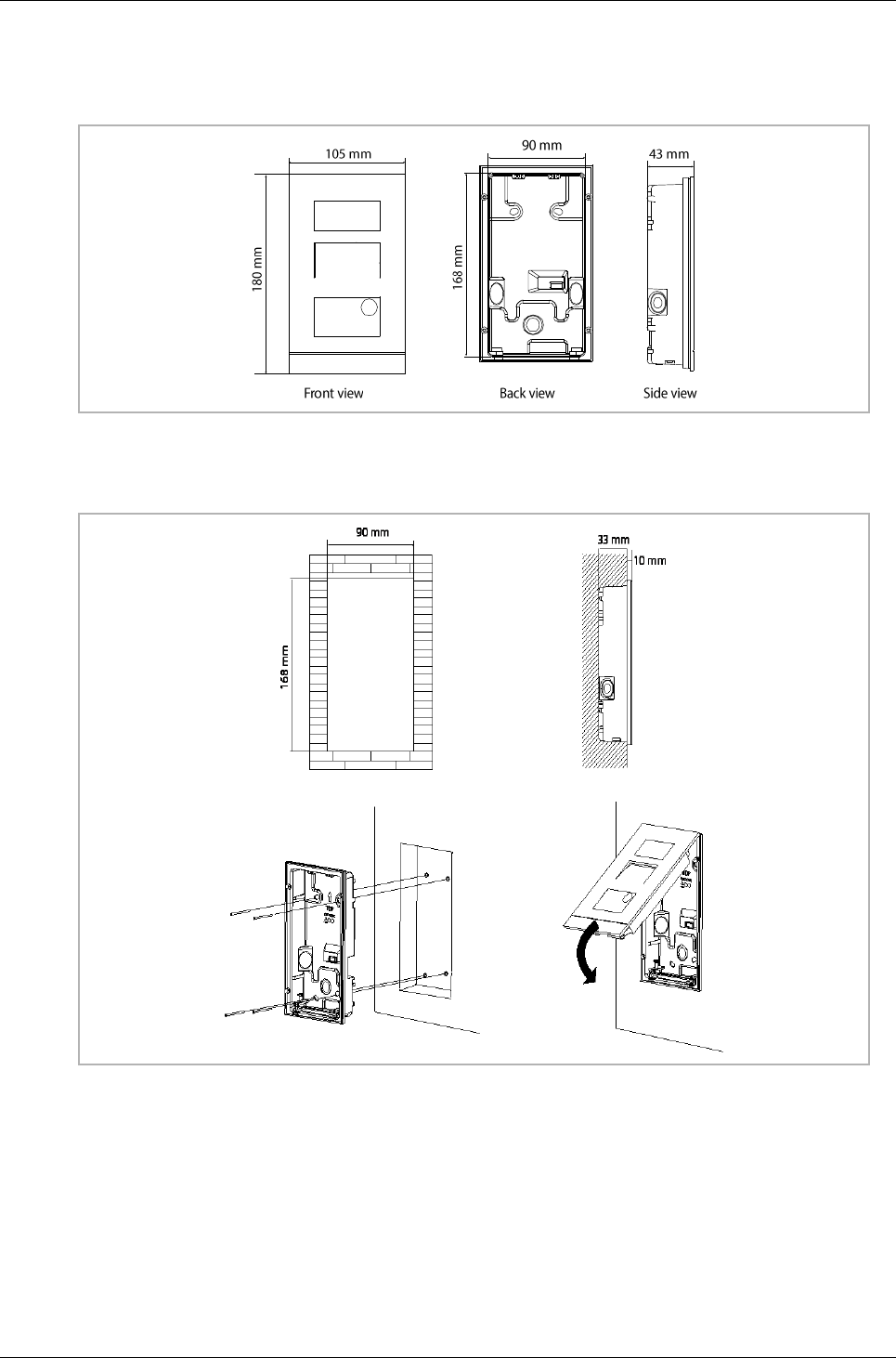
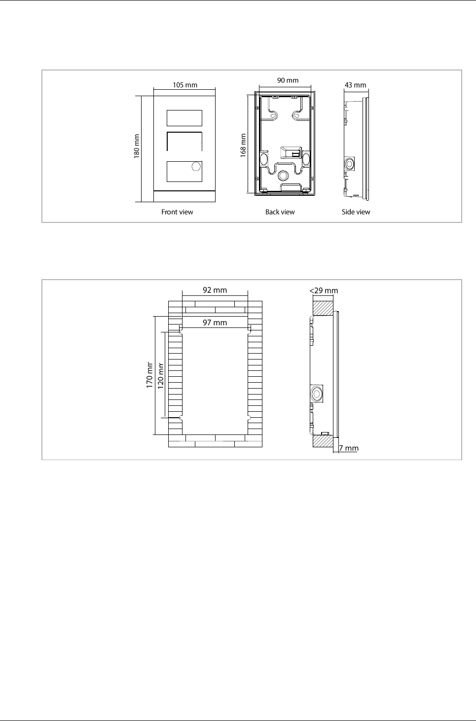
5.2.4 Cavity wall installation
Product dimension
Fig. 9
Installation dimension
Fig. 10
Mounting/Installation
Operating Instructions VER:1.3
│14
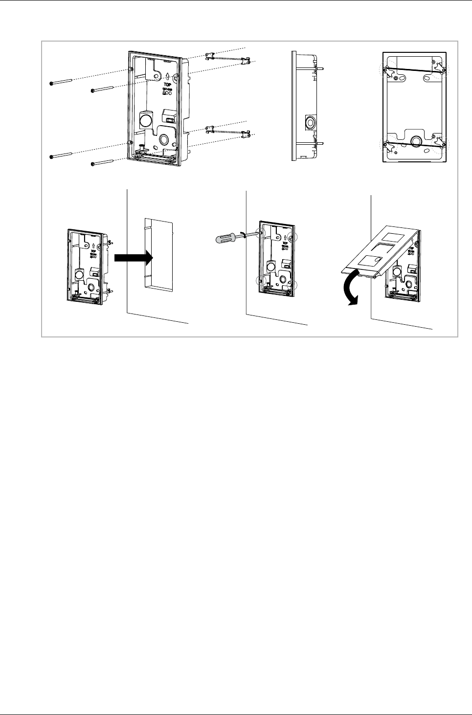
Cavity wall installation
Fig. 11
Mounting/Installation
Operating Instructions VER:1.3
│15
5.2.5 Dismantling
Fig. 12
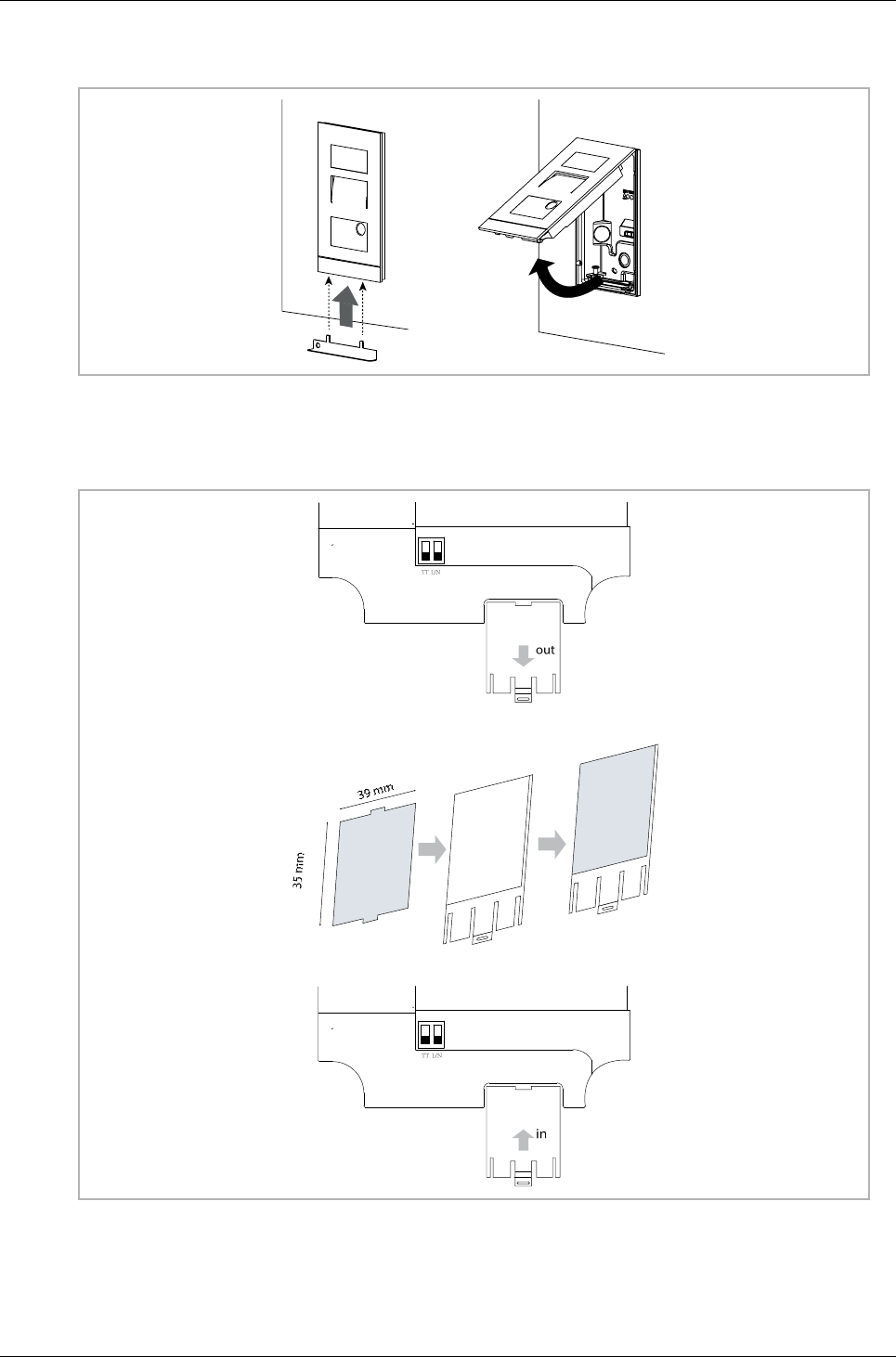
5.2.6 Replace the nameplate
Fig. 13

Mounting/Installation
Operating Instructions VER:1.3
│16
5.2.7 Installation situations
Note
The following installation situations must be avoided without fail to ensure
picture quality.
– Direct light
– Direct sunlight
– Extremely bright picture background
– Highly reflective walls on the opposite side of the door station
– Lamps or direct light sources
Commissioning
Operating Instructions VER:1.3
│17
6 Commissioning
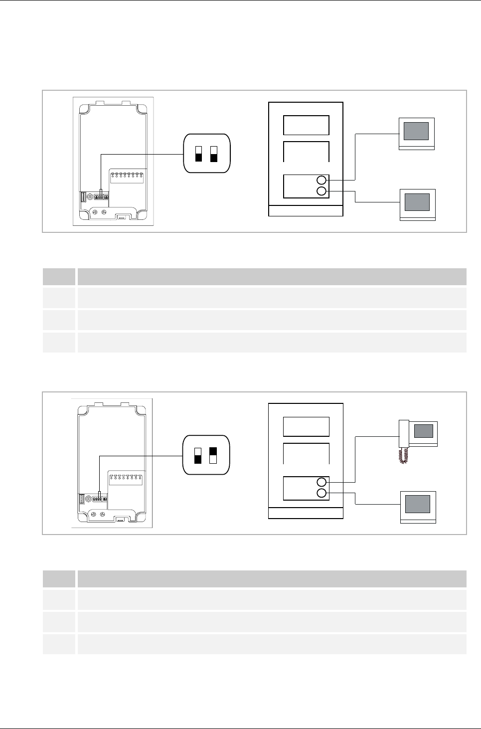
6.1 Configure functions of the 1st/2nd pushbutton
Fig. 14
No
Function
1
3-> OFF, 4-> OFF
2
Call apartment 001
3
Call apartment 002
Tab.5
Fig. 15:
No
Function
1
3-> OFF, 4-> ON
2
Call guard unit
3
Call apartment 001
Tab.6
DIP
3 4
0
5
001
002
DIP
3 4
0
5
001
G
Commissioning
Operating Instructions VER:1.3
│18
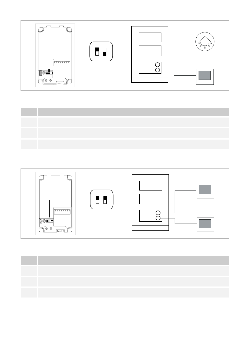
Fig. 16
No
Function
1
3-> ON, 4-> OFF
2
Switch on light
3
Call apartment 001
Tab.7
Fig. 17
No
Function
1
3-> ON, 4-> ON
2
Call apartment 001
3
Call apartment 002
Tab.8
DIP
3 4
0
5
001
DIP
3 4
0
5
002
001
Commissioning
Operating Instructions VER:1.3
│19
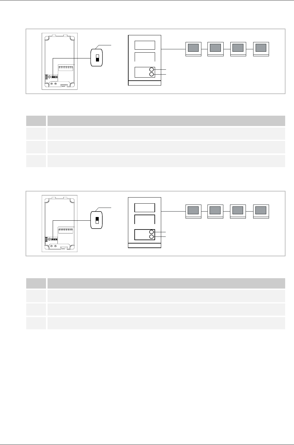
6.2 Setting general call function
Fig. 18
No
Function
1
2-> OFF
2
Call apartment 001, both 001 indoor stations ring
3
Call apartment 002, both 002 indoor stations ring
Tab.9
Fig. 19
No
Function
1
2-> ON
2
Call apartment 001, all 4 indoor stations (different address) ring
3
Call apartment 002, all 4 indoor stations (different address) ring
Tab.10
* If the "call forward function" has been set at the indoor station, this function will not work well.
For example, 001IS has set call forward to 002 IS, when press 1st round pushbutton on OS to
call 001 IS, if 001 IS doesn’t answer the call in 5s, it will not transfer to 002 IS.
DIP
2
1
2
3
0
5
001 001 002 002
DIP
2
1
2
3
0
5
001 002 003 004

Operation
Operating Instructions VER:1.3
│20
7 Operation
M
7.1 Manage ID cards by mini outdoor station
Programming
Function
Command
Indicated color of door open
Create admin card
Swipe card 1x
Green
Enter settings
Swipe admin card 1x
Orange
Tab.11
The system will take the first card swiped after powering up the system within 60s to be the
admin card.
After entering settings, following functionalities can be implemented:
Function
Command
Indicated color of door open
Enroll user
Swipe admin card 1x
Orange flash 1x
Swipe user card 1x
Green
Delete user
Swipe admin card 2x
Orange flash 2x
Swipe user card 1x
Green
Enroll new admin
Swipe admin card 3x
Orange flash 3x
Swipe new admin card 1x
Green
Delete admin
Swipe admin card 4x
Orange flash 4x
Swipe other admin card 1x
Green
Delete all users
Swipe admin card 5x
Orange flash quickly
Swipe admin card 1x
Green
Tab.12
During setting, please swipe the same admin card.
Function
Command
Indicated color of door open
Exit settings
Swipe admin card 1x or no
cards swiped within 15
seconds
--
Tab.13

Operation
Operating Instructions VER:1.3
│21
Open a door
Function
Command
Indicated color of door open
Open a door
Swipe the enrolled keycard
Green
Tab.14
Reset to factory default
Function
Command
Indicated color of door open
Reset to factory default
Press and hold the 1st button
for 3 s to enter configuration
mode.
Press and hold the 1st button
for 10 s to reset to factory
default.
Reboot the device
3 LED: green cycle flash
3 LED: OFF
Door open LED: red, green,
orange cycle flash
Tab.15
Technical data of ID card
Work frequency
Standard
Support ID card protocol
125KHz
ISO18000-2
EM4100, EM4205, EM4305,
EM4450, TK4100,
T5567/T5577
Tab.16

Notice
Operating Instructions VER:1.3
│22
Notice
We reserve the right to at all times make technical changes as well as changes to the contents
of this document without prior notice.
The detailed specifications agreed to at the time of ordering apply to all orders. ABB accepts no
responsibility for possible errors or incompleteness in this document.
We reserve all rights to this document and the topics and illustrations contained therein. The
document and its contents, or excerpts thereof, must not be reproduced, transmitted or reused
by third parties without prior written consent by ABB.
FCC ID: 2AEBL-M2131
FCC ID: 2AEBL-M2136
This device complies with Part 15 of the FCC Rules. Operation is subject to the following two
conditions: (1) this device may not cause harmful interference, and (2) this device must accept
any interference received, including interference that may cause undesired operation.
Only operate the device in accordance with the instructions supplied.
Changes or modifications to this unit not expressly approved by the party responsible for
compliance could void the user’s authority to operate the equipment.
This device complies with FCC radiation exposure limits set forth for an uncontrolled
environment. In order to avoid the possibility of exceeding the FCC radio frequency exposure
limits, human proximity to the antenna shall not be less than 20cm (8 inches) during normal
operation.
NOTE: This equipment has been tested and found to comply with the limits for a Class B digital
device, pursuant to part 15 of the FCC Rules. These limits are designed to provide reasonable
protection against harmful interference in a residential installation. This equipment
generates, uses and can radiate radio frequency energy and, if not installed and used in
accordance with the instructions, may cause harmful interference to radio communications.
However, there is no guarantee that interference will not occur in a particular installation. If
this equipment does cause harmful interference to radio or television reception, which can be
determined by turning the equipment off and on, the user is encouraged to try to correct the
interference by one or more of the following measures:
—Reorient or relocate the receiving antenna.
—Increase the separation between the equipment and receiver.
—Connect the equipment into an outlet on a circuit different from that to which the receiver is
connected.
—Consult the dealer or an experienced radio/TV technician for help.

Contact us
ABB (United Arab Emirates)
Industries(L.L.C)
P.O.Box 11070 Dubai-UAE
T : +971 4 3147 586
F : +971 4 3401 541
ABB (Turkey) Eletrik San.AS
ABB Elektrik Sanayi AS. Organize
Sanayi Bolgesi 2 Cadde
No: 16 Y. Dudullu-Istanbul
T : +90 216 528 2281
F : +90 216 528 2945
ABB (Thailand) Ltd.
161/1 SG Tower, 1st-4th Floor, Soi
Mahadlekluang 3, Rajdamri Road,
Lumpini, Pathumwan Bangkok
10330, Thailand
T : +66 2 6651 000
F : +66 2 6651 043
ABB (Korea) Ltd.
Oksan Bldg, 10th Fl. 157-33
Samsung-dong, Gangnam-gu,
135-090, Seoul, Korea
T : +82 2 5283 177
F : +82 2 5282 350
ABB Global Marketing - Lebanon
Down Town, Beirut, ebanon
T : +961 1983 724/5
F : +961 1983 723
ABB (India) Ltd.
Plot No.1, Sector-1B,
I.I.E.SIDCUL,
Haridwar-249403.India
T : +91 133 423 5447
F : +91 133 423 5449
ABB Australia Pty Ltd.
601 Blackburn Road
3168, Notting Hill, Victoria,
Australia
T : +61 3 8577 7139
F : +61 3 9545 0415
www.abb.com
Approvals and Compliances
ABB (Vietnam) Ltd.
Km 9 National Highway 1A ,
Hoang Liet, Hoang Mai, Hanoi,
Vietnam
T : +84 4 3861 1010
F : +84 4 3861 1009
ABB (KSA) Electrical Industries
Co. Ltd.
P.O.Box 325841, Riyadh 11371
T : +966 1 1484 5600
F : +966 1 1206 7609
ABB (Russia) Ltd.
3121 Wiring Accessories
30/1 bld.2, Obrucheva str. RU
T : +7 495 777 2220
F : +7 495 777 2220
ABB Malaysia Sdn Bhd
Block A, Level 2, Lot 608, Jalan
SS13/IK 47500 Subang Jaya
Selangor
T : +60 3 5628 4888
F : +60 3 5635 8200
ABB (Hong Kong) Ltd.
3 Dai Hei Street, Tai Po Industrial
Estate, Tai po, Hong Kong
T : +852 2 9293 912
F : +852 2 9293 505
ABB Pte. Ltd.
2 Ayer Rajah Crescent,
Singapore 139935
T: + 65 6 7765 711
F: + 65 6 7780 222
Notice
We reserve the right to at all times
make technical changes as well as
changes to the contents of this
document without prior notice.
The detailed specifications agreed
upon apply for orders. ABB accepts
no responsibility for possible errors
or incompleteness in this document.
We reserve all rights to this
document and the topics and
illustrations contained therein. The
document and its contents, or
extracts thereof, must not be
reproduced, transmitted or reused
by third parties without prior written
consent by ABB
Copyright© 2016 ABB
All rights reserved
Operating Instructions VER:1.3 │ 20.06.2017