ABB Xiamen Smart Technology M2136 Mini video outdoor station User Manual Product manual
ABB Genway Xiamen Electrical Equipment Co., Ltd Mini video outdoor station Product manual
UserManual.wiki
>
ABB Xiamen Smart Technology
>
M2136 User Manual
>
Product manual
Contents
1.
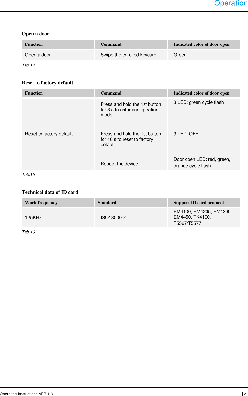
Operating instruction
2.
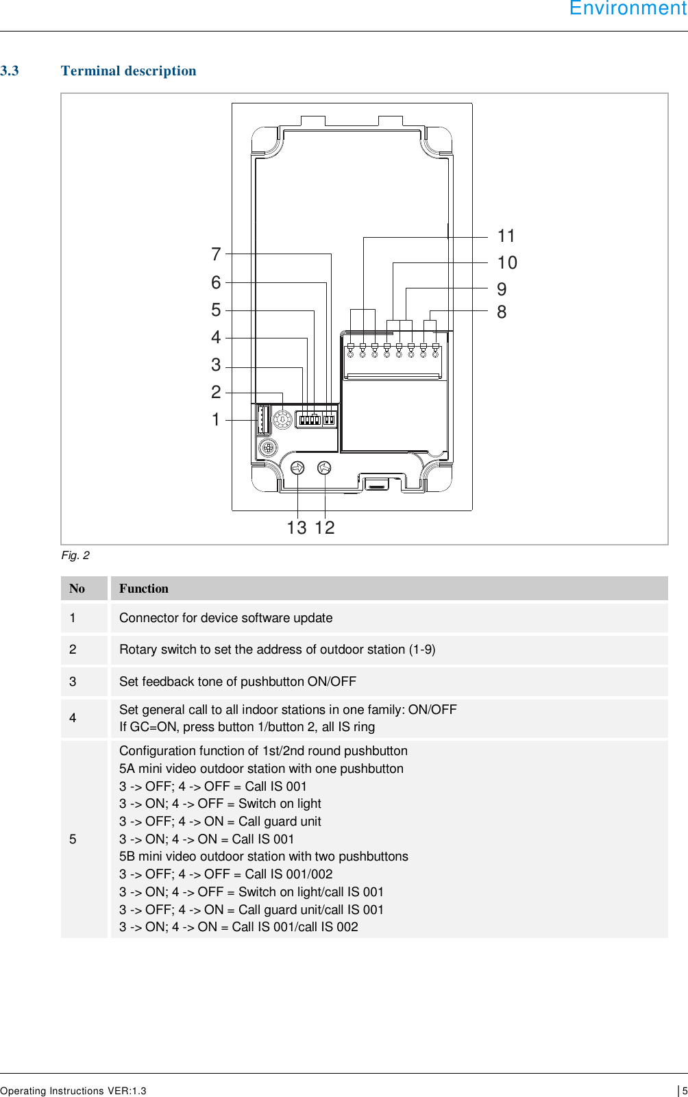
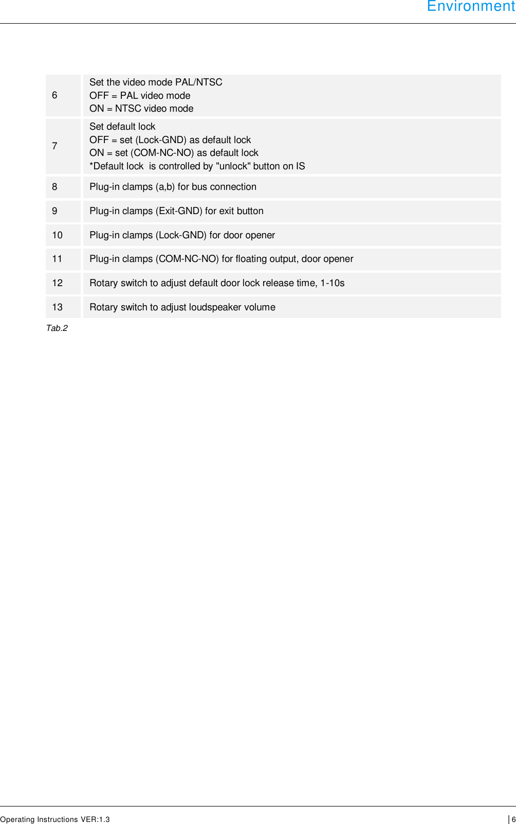
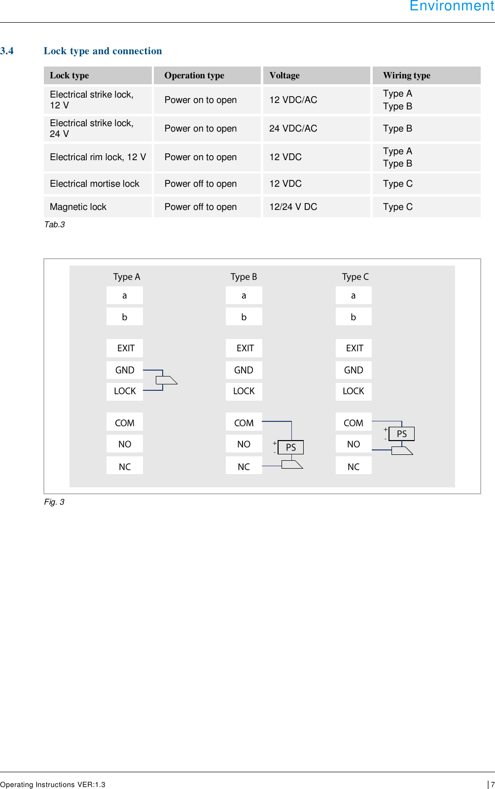
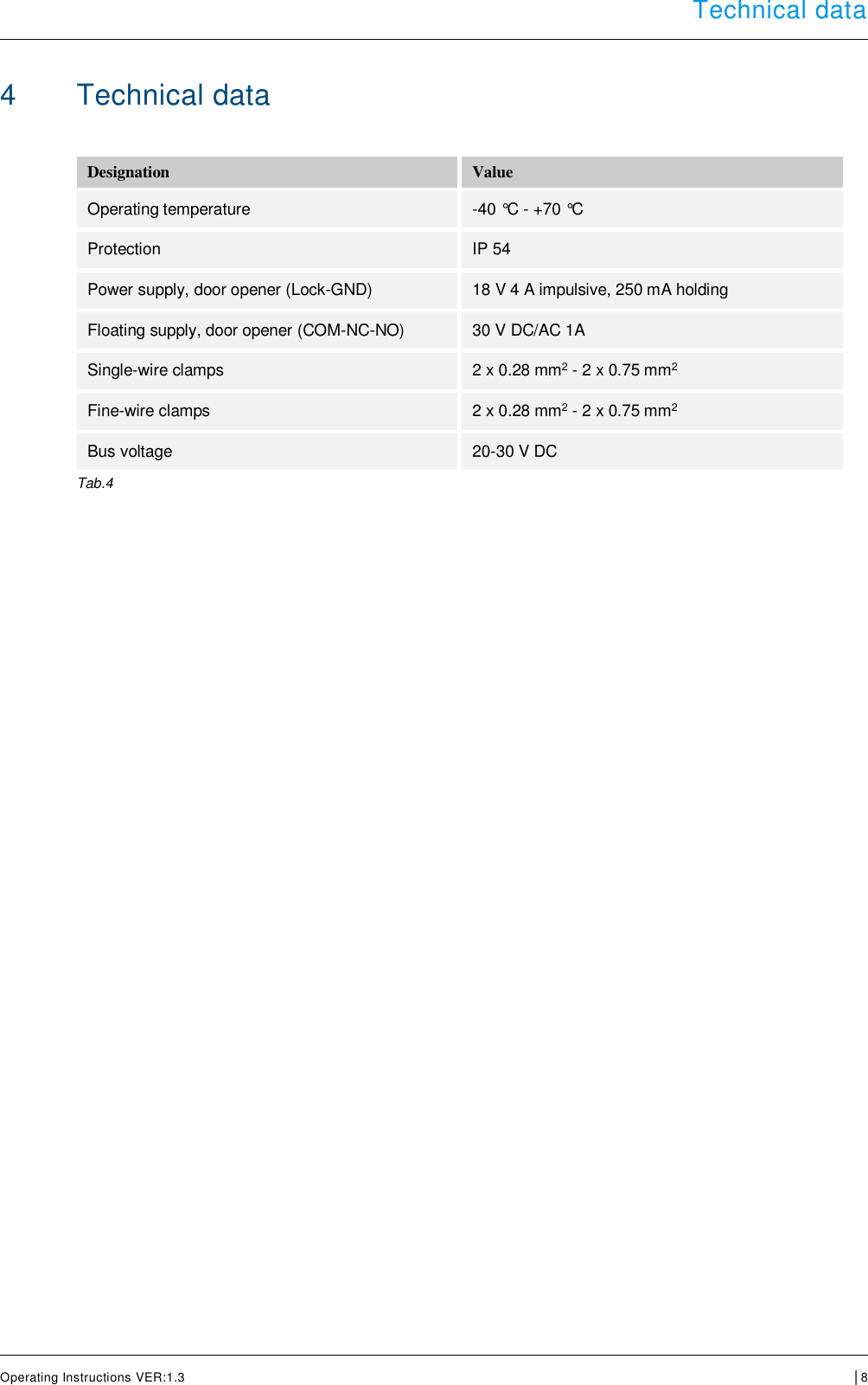
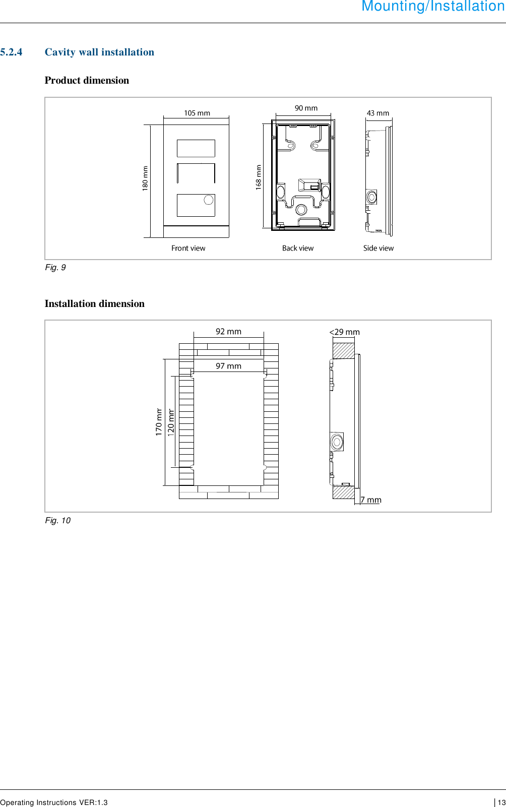
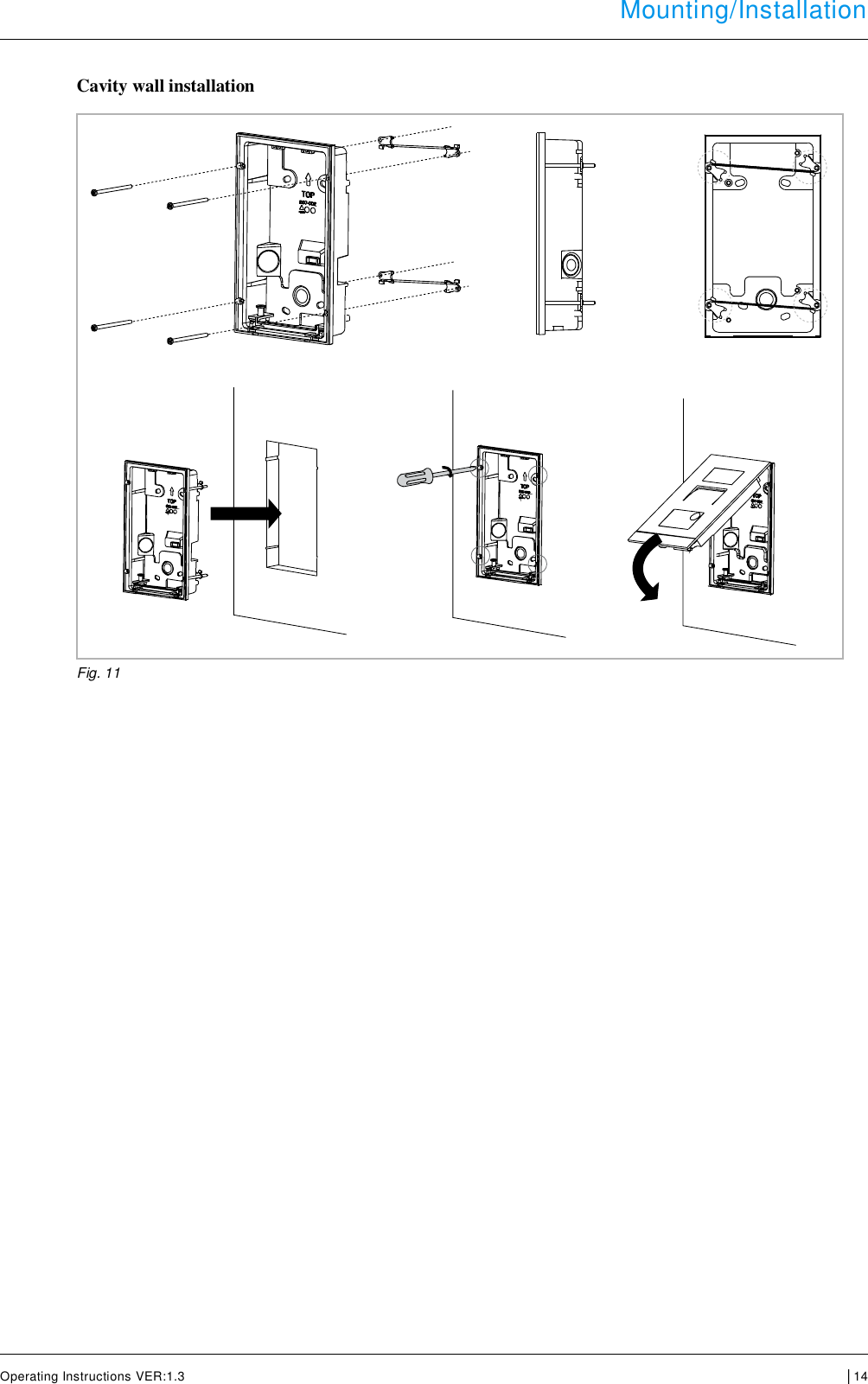
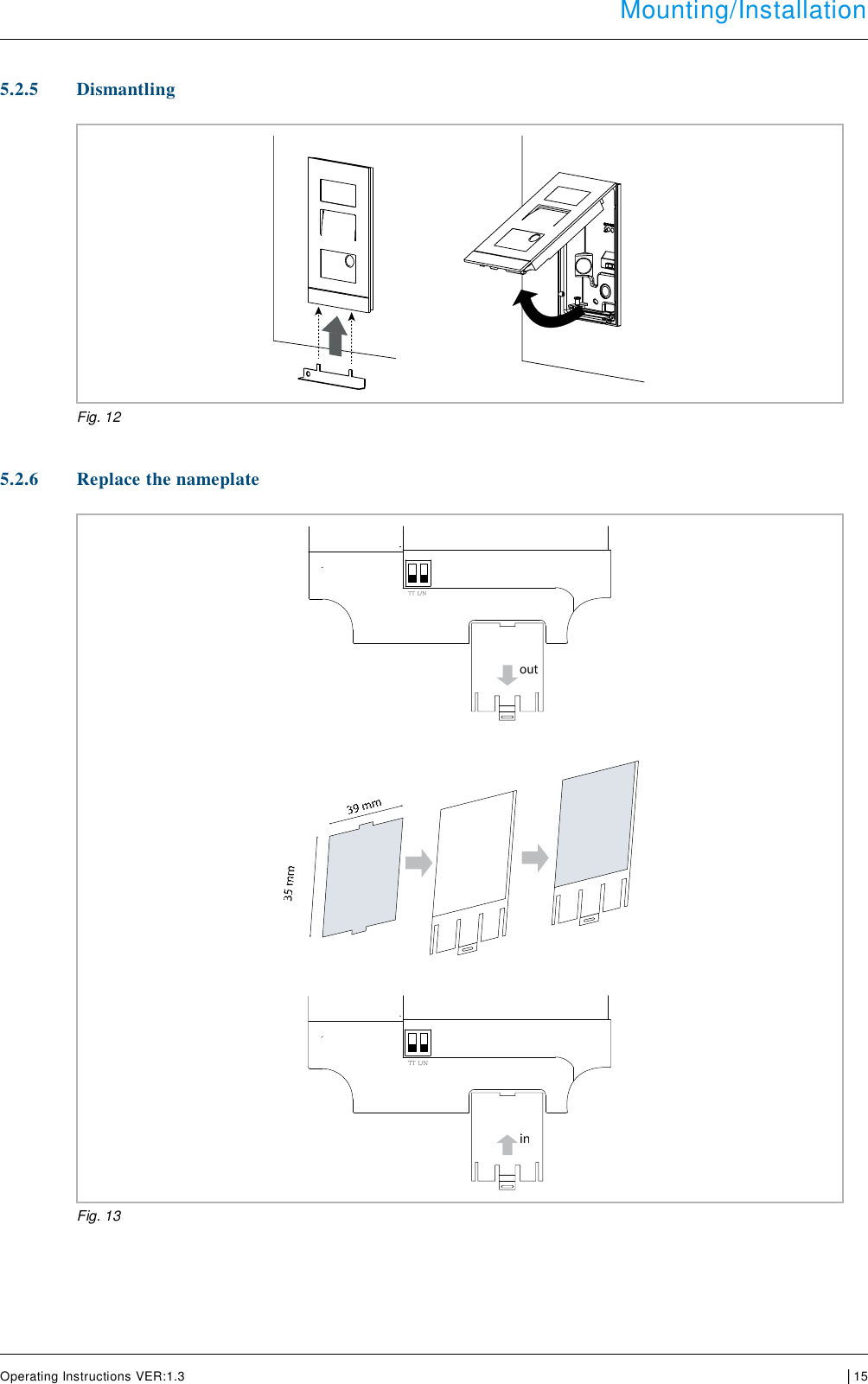
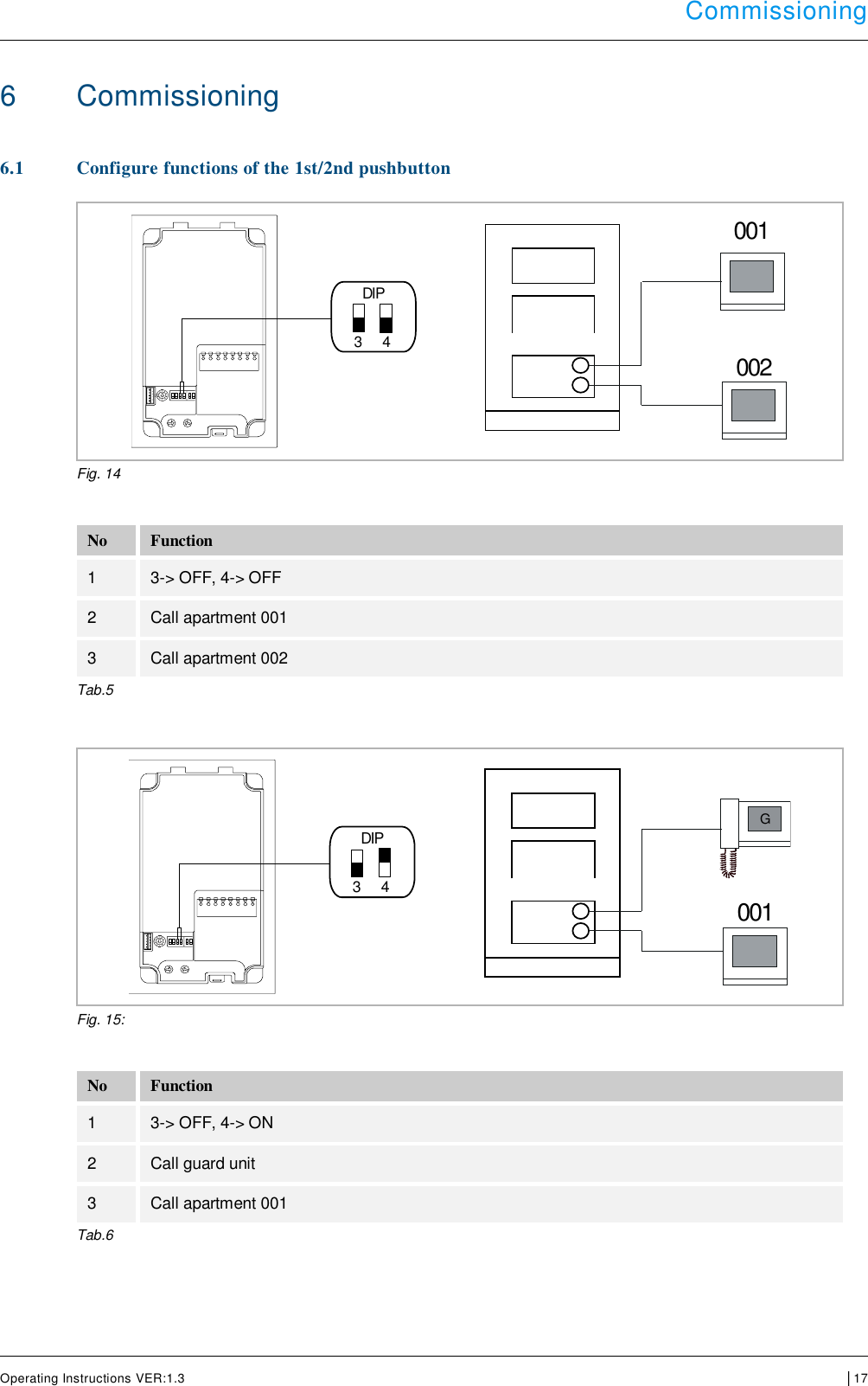
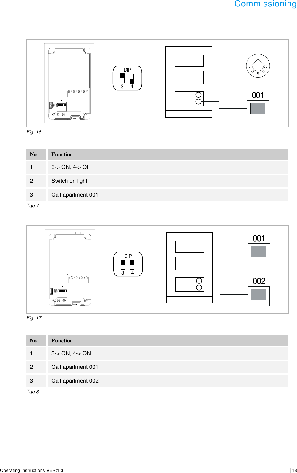
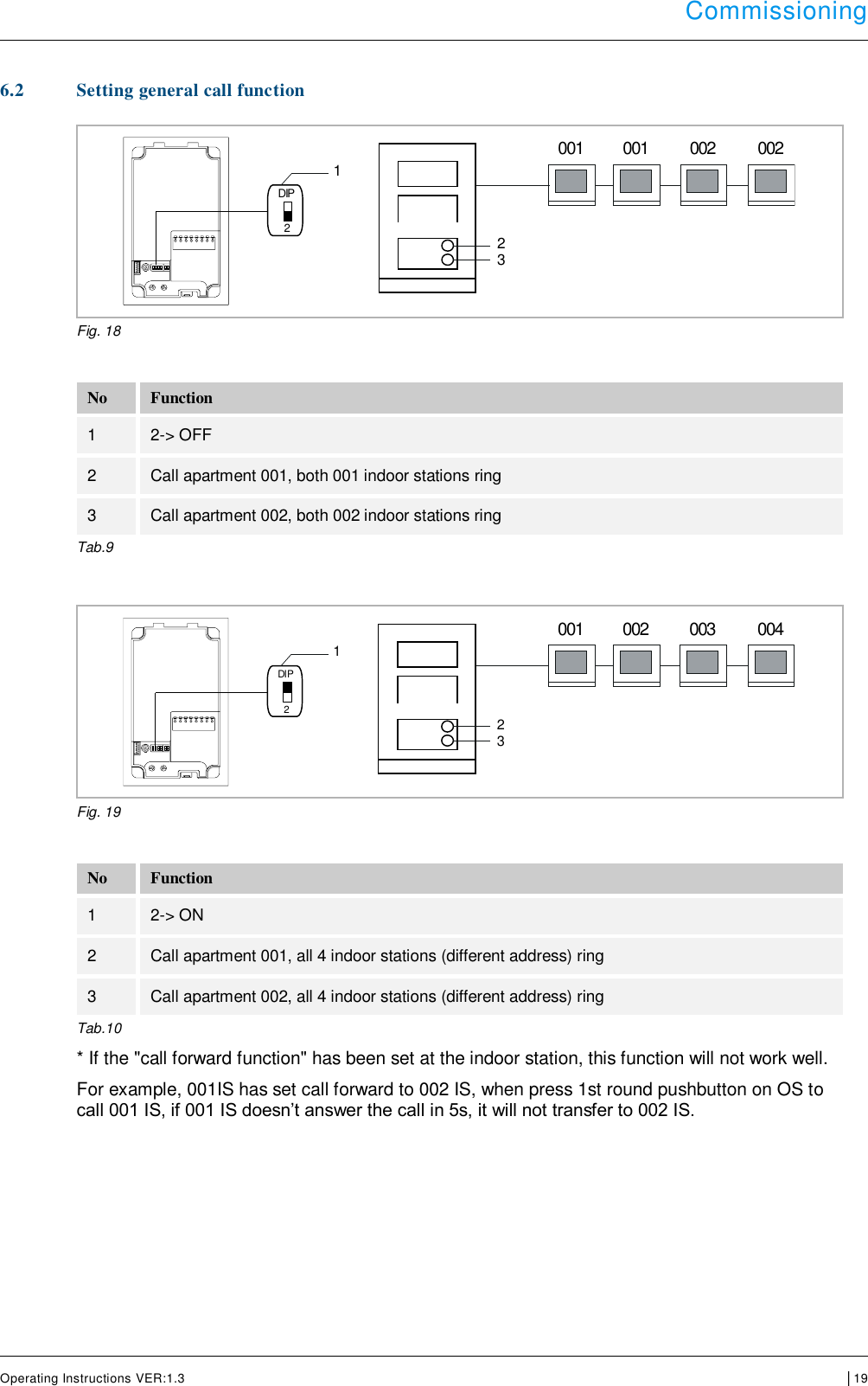
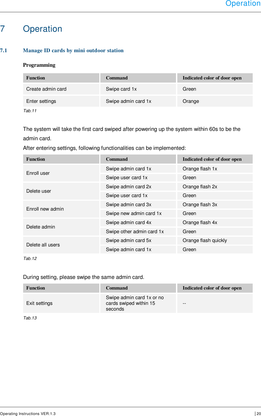
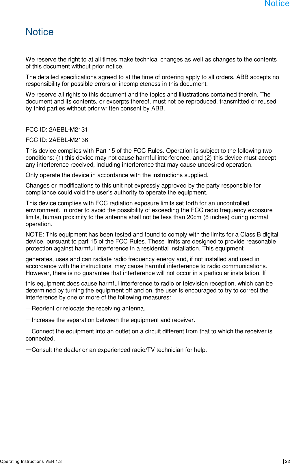
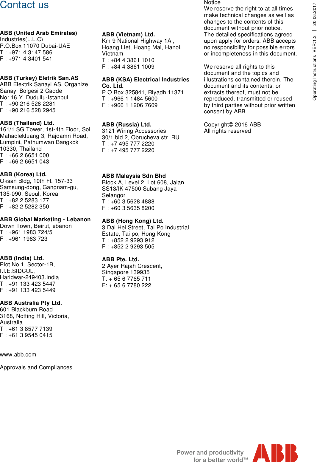
Product manual
Product manual
Navigation menu
Upload a User Manual
Namespaces
Wiki Guide
HTML
PDF
Info
Views
User Manual
Discussion / Help
Navigation