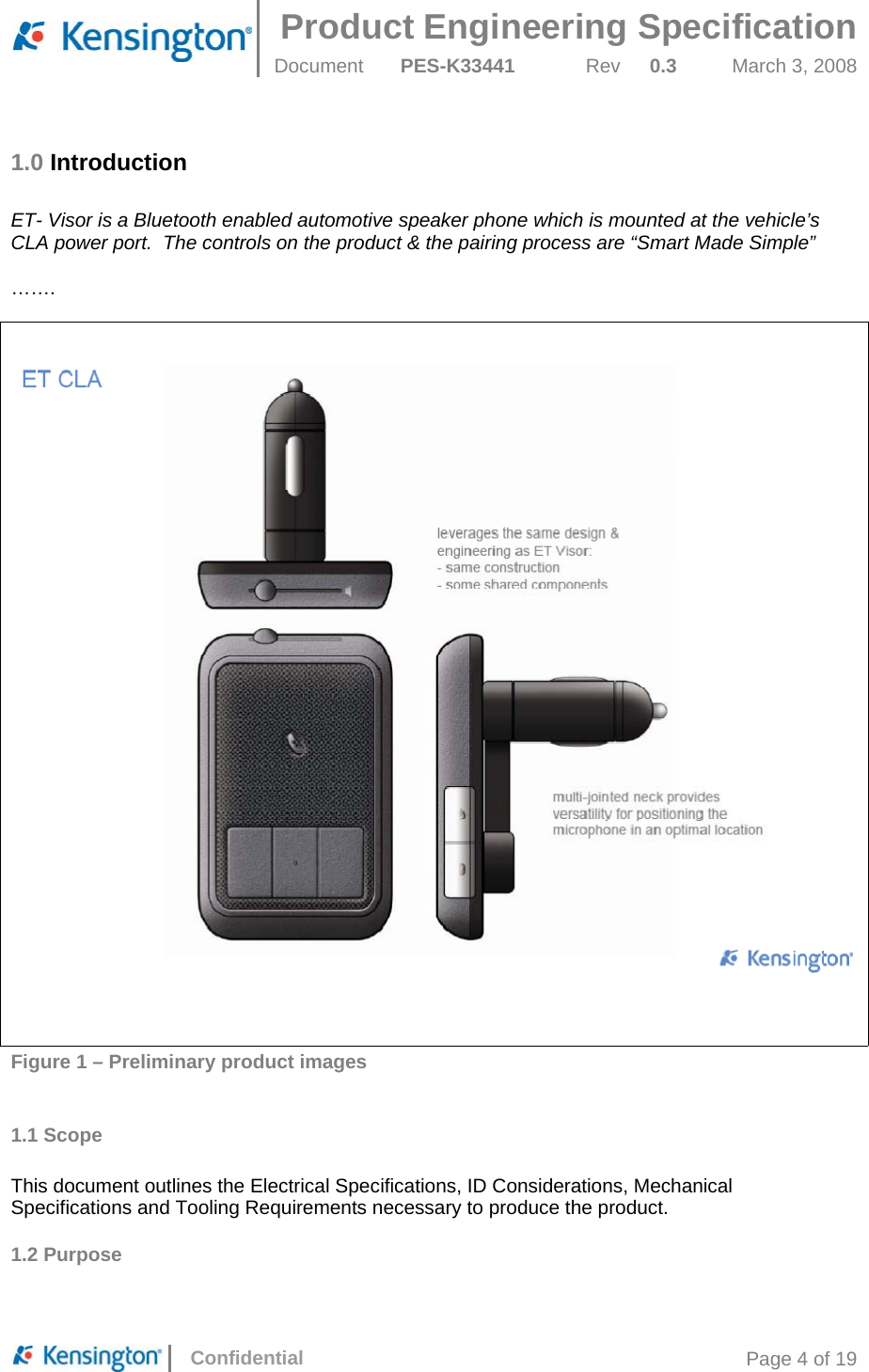
ACCO M01043 Hands-Free Car Kit for iPhone & BT Phones User Manual PES K33441 030308x
ACCO Brands, Inc. Hands-Free Car Kit for iPhone & BT Phones PES K33441 030308x
UserManual.wiki
>
ACCO
>
M01043 User Manual
User manual
Navigation menu
Upload a User Manual
Namespaces
Wiki Guide
HTML
PDF
Info
Views
User Manual
Discussion / Help
Navigation
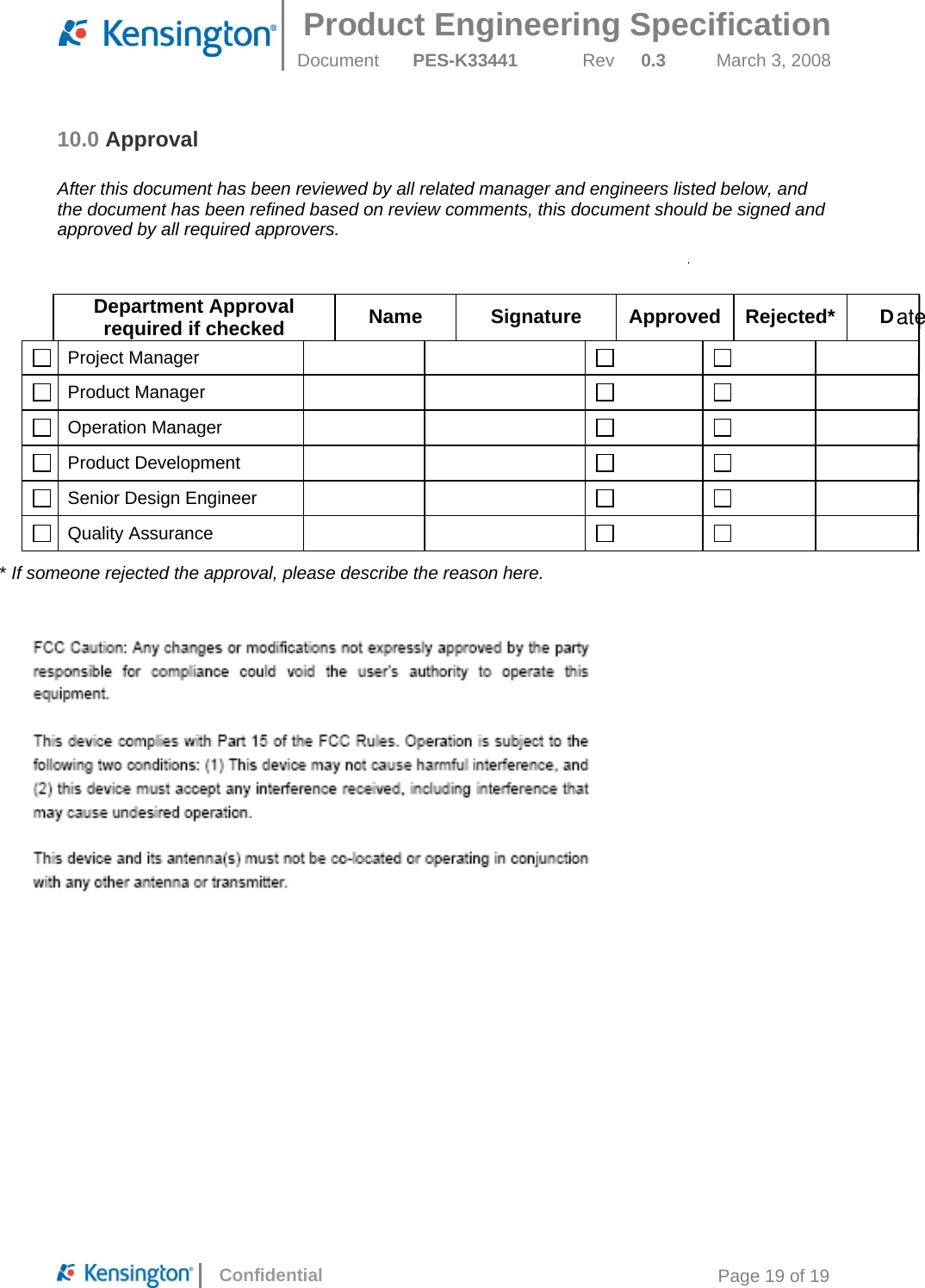
![Product Engineering Specification Document PES-K33441 Rev 0.3 March 3, 2008 Confidential Page 10 of 19 3.4 BT Requirements Chipset: CSR BC05 BT 2.1 Up to 8 Paired devices. One at a time 3.5 Audio Requirements Echo & Noise Cancelling • Audio Out: Speaker o Power (minimum) : 1W continuous, 2W peak. o Sensitivity (SPL): min 82 +/- 3dB o Impedance: 8 Ohm +/- 15% o Lowest resonant frequency [Fo]: 280 – 480 Hz o Effective frequency Range (minimum): Fo – 10kHz o THD < 3% • Audio In: measurement method tbd o Generally the intent is to filter out all external noise factors including but not limited to: • Road Noise • Car Noise • Wind Noise • Tire Noise • Echo • Other ambient noises o The prime audio solution (firmware based) for ET will be provided by Primax o Echo rejection: >42 dB o Convergence in presence of back ground noise: < 1.0 sec o Noise Cancellation: 12 dB o No Distortion or speech clipping o Comfort noise injection for natural sounding conversations o Enhanced Non-linear processor for suppression of residual echo o Microphone: • Omni directional microphone to be used • To be isolated via a rubber “boot” to prevent vibration transmission • Not to be rigidly mounted to the PCB, should be mounted to the plastics and attached to the PCB via flying leads • RF filtering a must to reduce TDMA noise issues • 6mm diameter microphone to be used • Microphone SNR to be min 55 dB • The microphone is to be located on the front face plate for optimum user orientation. • Sensitivity greater than -45 dBV at 1KHz • Reference Microphone: • Kingstate Microphone with flying leads. • KECC2244WBL-G9U](https://usermanual.wiki/ACCO/M01043/User-Guide-1047841-Page-10.png)