ACE&EASTMAN He 800B Service Manual User
2016-10-16
User Manual: ACE&EASTMAN He-800B Service Manual
Open the PDF directly: View PDF ![]() .
.
Page Count: 178 [warning: Documents this large are best viewed by clicking the View PDF Link!]
- Cover
- SAFETY INSTRUCTIONS
- CONTENTS
- 1. SPECIFICATIONS
- 2. NOTES ON HANDLING
- 3. FUNCTION SETTINGS
- 3-1. List of special functions when power is turned on
- 3-2. List of advanced functions
- 3-3. Setting memory switches (Advanced)
- 3-4. List of memory switches
- 3-5. Pedal operation mode setting method
- 3-6. Checking the error history
- 3-7. Input checking method
- 3-8. Output checking method
- 3-9. Confirming software version
- 3-10. Protection settings
- 4. USING SD CARDS
- 4-1. Notes on handling SD cards (commercially available)
- 4-2. Structure of an SD card folder
- 4-3. Preparation for reading and writing data
- 4-4. Reading program data (parameters)
- 4-5. Writing program data (parameters) to an SD memory card
- 4-6. Reading memory switch data
- 4-7. Writing memory switch data to the SD card
- 4-8. Reading sewing machine data
- 4-9. Writing sewing machine data to an SD card
- 4-10. Writing error log data to an SD card
- 4-11. Updating the control program version
- 5. MECHANICAL DESCRIPTIONS
- 5-1. Needle bar and thread take-up mechanisms
- 5-2. Upper shaft, lower shaft and rotary hook mechanisms
- 5-3. Needle zigzag mechanism
- 5-4. Presser foot lifter mechanism
- 5-5. Feed mechanism
- 5-6. Cutter mechanism
- 5-7. Thread breakage detection mechanism
- 5-8. Tension release mechanism
- 5-9. Upper thread trimmer mechanism
- 5-10. Lower thread trimmer mechanism
- 6. ASSEMBLY
- 6-1. Lower shaft and idle pulley mechanisms
- 6-2. Lower thread trimmer mechanism
- 6-3. Feed mechanism
- 6-4. Threading mechanism
- 6-5. Presser lifter mechanism
- 6-6. Needle zigzag mechanism
- 6-7. Cutter mechanism
- 6-8. Upper shaft and tension pulley mechanisms
- 6-9. Lubrication mechanism
- 6-10. Needle bar and thread take-up mechanisms
- 6-11. Presser bar mechanism
- 6-12. Upper thread trimmer mechanism
- 6-13. Thread breakage detector mechanism
- 6-14. Rotary hook mechanism
- 6-15. Covers
- 7. ADJUSTMENT
- 7-1. Notes on making adjustments
- 7-2. Adjusting the home position
- 7-3. Adjusting the needle bar height
- 7-4. Adjusting the needle and hook timing
- 7-5. Adjusting the inner rotary hook and rotary hook holder overlap
- 7-6. Adjusting the work clamp pressure
- 7-7. Adjusting the work clamp lift amount
- 7-8. Adjusting the work clamp lateral position
- 7-9. Adjusting the cutter home position sensor position
- 7-10. Adjusting the cutter installation position
- 7-11. Adjusting the cutter installation height
- 7-12. Adjusting the upper thread trimming
- 7-12-1. Adjusting the longitudinal feed arm assembly position
- 7-12-2. Adjusting the trimmer driving arm assembly position
- 7-12-3. Adjusting the lateral position of the upper thread scissors at the sewing start
- 7-12-4. Adjusting the longitudinal position of the upper thread scissors
- 7-12-5. Adjusting the cutting depth of the upper thread scissors
- 7-12-6. Adjusting the installation height of the upper thread scissors
- 7-12-7. Adjusting the upper thread scissors gradual opening timing
- 7-12-8. Adjusting the upper thread scissors opening timing
- 7-12-9. Adjusting the overlapping amount of the upper thread scissors and the work clamp
- 7-13. Adjusting the lower thread trimming
- 7-14. Adjusting the bobbin presser
- 7-15. Adjusting the thread breakage detector
- 7-16. Adjusting the thread tension at the tack tension control
- 7-17. Adjusting the thread tension at the zigzag tension control
- 7-18. Adjusting the upper thread feeding amount
- 7-19. Adjusting the rotary hook lubrication
- 7-20. Adjusting the upper shaft motor reference position
- 7-21. Standard settings for treadle depression stroke
- 8. INSTALLING THE 3-PEDAL FOOT SWITCH (OPTION)
- 9. ELECTRIC MECHANISM
- 10. TABLE OF ERROR CODES
- 11. TROUBLESHOOTING
- 11-1. Upper thread breakage
- 11-2. Skipped stitches
- 11-3. Uneven seams (1) …… At the sewing start
- 11-4. Uneven seams (2) …… Lower thread is lifted up at the sewing start
- 11-5. Uneven seams (3) ……Seam lifts up at the sewing start
- 11-6. Uneven seams (4) …… Uneven sewing pitch at the sewing start
- 11-7. Uneven seams (5)……Poor rounding of seam
- 11-8. Uneven seams (6) …… Around rear tack or front tack
- 11-9. Uneven seams (7) …… Loose thread end at end backtack
- 11-10. Uneven seams (8) …… Thread sticking out at end backtack
- 11-11. Uneven seams (9) …… Sticking in needle plate
- 11-12. Uneven seams (10) …… All stitches
- 11-13. Upper thread run out
- 11-14. Unraveling of thread trimmed by upper thread trimmer assembly
- 11-15. Upper thread miss-trimming
- 11-16. Needle strikes upper thread trimmer
- 11-17. Needle breakage
- 11-18. Imperfect cutter function (imperfect material cutting)
- 11-19. Cutter does not return
- 11-20. Cutter and upper thread trimmer touch
- 11-21. Seam is cut
- 11-22. Upper thread miss-winding
- 11-23. Work clamp is not raised (1) ……Error does not occur.
- 11-24. Work clamp is not raised (2) ……Error occurs.
- 11-25. Lower thread is not trimmed (pulls when material is removed)
- 11-26. Feed mechanism does not move and error occurs.
- 11-27. Needle does not zigzag or noise occurs when needle zigzags
- 11-28. Sewing machine stops during sewing
- 11-29. Upper shaft does not rotate as far as the needle up stop position
- 11-30. Operation panel display freezes and operation is not possible
- Back Cover
HE-800B
Please read this manual before making any adjustments.
ELECTRONIC DIRECT DRIVE LOCKSTITCH BUTTON HOLER
SERVICE MANUAL
HE-800B
This service manual is intended for HE-800B; be sure to read the HE-800B instruction manual before this manual.
Carefully read the “SAFETY INSTRUCTIONS” below and the whole of this manual to understand this product before you
start maintenance.
As a result of research and improvements regarding this product, some details of this manual may not be the same as those
for the product you purchased.
If you have any questions regarding this product, please contact a Brother dealer.

i
HE-800B
SAFETY INSTRUCTIONS
[1] Safety indications and their meanings
This service manual and the indications and symbols that are used on the machine itself are provided in order to ensure
safe operation of this machine and to prevent accidents and injury to yourself or other people.
The meanings of these indications and symbols are given below.
Indications
DANGER
The instructions which follow this term indicate situations where failure
to follow the
instructions will result in death or serious injury.
WARNING
The instructions which follow this term indicate situations where failure to follow the
instructions could result in death or serious injury.
CAUTION
The instructions which follow
this term indicate situations where failure to follow the
instructions may result in minor or moderate injury.
Symbols
・・・・・・ This symbol ( ) indicates something that you should be careful of. The picture inside the triangle
indicates the nature of the caution that must be taken.
(For example, the symbol at left means “beware of injury”.)
・・・・・・ This symbol ( ) indicates something that you must not do.
・・・・・・ This symbol ( ) indicates something that you must do. The picture inside the circle indicates the
nature of the thing that must be done.
(For example, the symbol at left means “you must make the ground connection”.)
ii
HE-800B
[2] Notes on safety
DANGER
Wait at least 5 minutes after turning off the power
switch and disconnecting the power cord from the wall outlet
before opening the control box cover. Touching areas where high voltages are present will result in serious injury
from electric shocks.
WARNING
Do not allow any liquids to get onto this
sewing machine, otherwise fire, electric shocks or operating problems may
occur.
If any liquid gets inside the sewing machine (machine head or control box), immediately turn off the power and
disconnect the power plug from the electrical outlet, and then
contact the place of purchase or a qualified
technician.
CAUTION
Environmental requirements
Use the sewing machine in an area which is free from
sources of strong electrical noise such as electrical
line noise or static electric noise.
Sources
of strong electrical noise may cause
problems with correct operation.
Any fluctuations in the power supply voltage should
be within ±10% of the rated voltage for the machine.
Voltage fluctuations which are greater than this may
cause problems with correct operation.
The power supply capacity should be greater than the
requirements for the sewing machine’s power
consumption.
Insufficient power supply capacity may cause
problems with correct operation.
The ambient temperature should be within the range
of 5°C to 35°C during use.
Temperatures which are lower or higher than this
may cause problems with correct operation.
The relative humidity should be within the range of
45%
to 85% during use, and no dew formation should
occur in any devices.
Excessively dry
or humid environments and dew
formation may cause problems with correct operation.
In the event of an electrical storm, turn off the power
and disconnect the power cord from the wall outlet.
Lightning may cause problems with correct operation.
Installation
Machine installation should only be carried out by a
qualified technician.
Contact your Brother dealer or a qualified electrician
for any electrical work that may need to be done.
The sewing machine weighs approximately 56 kg.
The
installation should be carried out by two or more
people.
Do not connect the power cord until installation is
complete, otherwise the machine may operate if the
treadle is depressed by mistake, which could result in
injury.
Use both hands to hold the machine head when tilting
it back or returning it to its original position. If only
one hand is used, the weight of the machine head
may cause your hand to slip, and your hand may get
caught.
Be sure to connect the ground. If the ground
connection is not secur
e, you run a high risk of
receiving a
serious electric shock, and problems with
correct operation may also occur.
All cords should be secured at least 25 mm away
from
any moving parts. Furthermore, do not
excessively bend the cords or secure them too firmly
with staples,
otherwise there is the danger that fire or
electric shocks could occur.
Install the safety
covers to the machine head and
motor.
If using a work table which has casters, the casters
should be secured in such a way so that they cannot
move.
Be sure to wear protective goggles and gloves when
handling the lubricating oil and grease, so that they
do
not get into your eyes or onto your skin, otherwise
inflammation can result.
Furthermore, do not drink the oil or eat the grease
under any circumstances, as they can cause vomiting
and diarrhea.
Keep the oil out of the reach of children.
iii
HE-800B
CAUTION
Sewing
This sewing machine should only be used by
operators
who have received the necessary training
in safe use beforehand.
The sewing machine should not be used for any
applications other than sewing.
Be sure to wear protective goggles when using the
machine.
If goggles are not worn, there is the danger that if a
needle breaks, parts of the broken needle may enter
your eyes and injury may result.
Turn off the power switch at the following times,
otherwise the machine may operate if the treadle is
depressed by mistake, which could result in injury.
• When replacing the needle and bobbin
• When not using the machine and when leaving the
machine unattended
Use threading mode or turn off the power first in order
to carry out threading.
If using a work table which has casters, the casters
should be secured in such a way so that they cannot
move.
Attach all safety devices before using the sewing
machine. If the machine is used without these
devices attached, injury may result.
Do not touch any of the moving parts or press any
objects against the machine while sewing, as this
may
result in personal injury or damage to the
machine.
If an error occurs in machine operation, or if abnormal
noises or smells are noticed, immediately turn off the
power switch. Then contact your nearest Brother
dealer or a qualified technician.
If the machine develops a problem, contact your
nearest Brother dealer or a qualified technician.
Cleaning
Turn off the power switch before carrying out
cleaning,
otherwise the machine may operate if the
treadle is depressed by mistake, which could result in
injury.
Be sure to wear protective goggles and gloves when
handling the lubricating oil and grease, so that they
do
not get into your eyes or onto your skin, otherwise
inflammation can result.
Furthermore, do not drink the oil or eat the grease
under any circumstances, as they can cause vomiting
and diarrhea.
Keep the oil out of the reach of children.
Maintenance and inspection
Maintenance and inspection of the sewing machine
should only be carried out by a qualified technician.
Ask your Brother dealer or a qualified electrician to
carry out any maintenance and inspection of the
electrical system.
Turn off the power switch and disconnect the power
cord from the wall outlet at the following times,
otherwise the machine may operate if the treadle is
depressed by mistake, which could result in injury.
• When carry
ing out inspection, adjustment and
maintenance
• When replacing consumable parts such as the
rotary hook
Turn off the power switch before inserting or
removing the plug, otherwise damage to the control
box could result.
If the power switch needs to be left on when carrying
out some adjustment, be extremely careful to observe
all safety precautions.
Use both hands to hold the machine head when tilting
it back or returning it to its original position. If only
one hand is used, the weight of the machine head
may cause your hand to slip, and your hand may get
caught.
When replacing parts and installing optional
accessories, be sure to use only genuine Brother
parts.
Brother will not be held responsible for any accidents
or problems resulting from the use of non-genuine
parts.
If any safety devices have been removed, be
absolutely sure to re-
install them to their original
positions
and check that they operate correctly before
using the machine.
To prevent accidents and problems, do not modify
the machine yourself.
Brother will not be held responsible for any accidents
or problems resulting from modifications made to the
machine.
iv
HE-800B
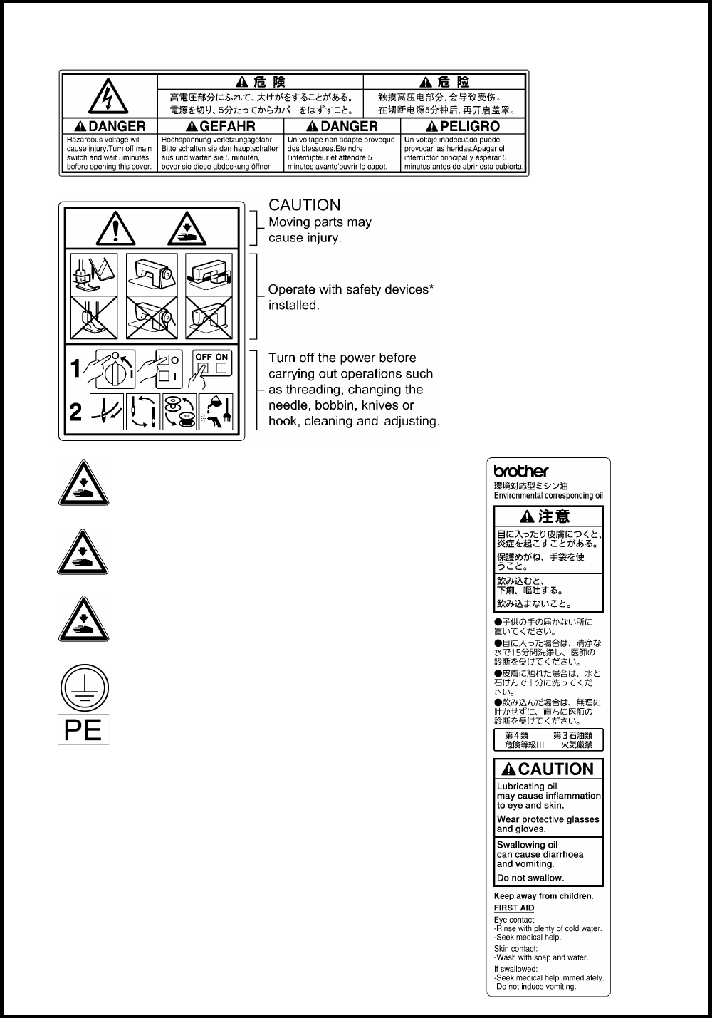
[3] Warning labels
The following warning labels appear on the sewing machine.
Please follow the instructions on the labels at all times when using the machine. If the labels have been removed or
are difficult to read, please contact your nearest Brother dealer.
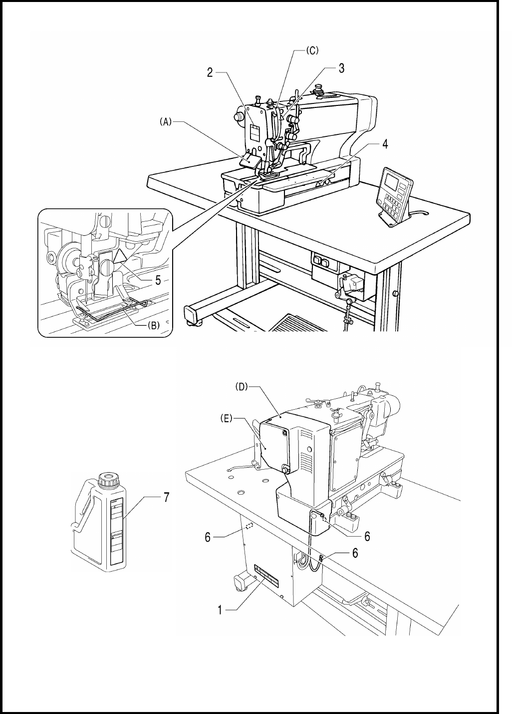
1
2
*Safety devices
(A) Eye guard
(B) Finger guard
(C) Thread take-up cover
(D) Motor cover
(E) Slide cover
3
Be careful to avoid injury from the moving thread
take-up.
7
4
Be careful not to get your hands caught when returning
the machine head to its original position after it has
been tilted.
5
Be careful to avoid injury from the moving cutter.
6
Be sure to connect the ground. If the ground connection
is not secure, you run a high risk of receiving a serious
electric shock, and problems with correct operation may
also occur.
v
HE-800B
Oil tank
(accessory)
4732M
4731M
4730M
HE-800B
CONTENTS
1. SPECIFICATIONS ................................. 1
1-1. Specifications .......................................................... 1
1-2. Standard sewing pattern list .................................... 2
2. NOTES ON HANDLING ......................... 3
3. FUNCTION SETTINGS .......................... 4
3-1. List of special functions when power is turned
on ........................................................................... 4
3-2. List of advanced functions ..................................... 6
3-3. Setting memory switches (Advanced) .................... 7
3-4. List of memory switches ......................................... 8
3-5. Pedal operation mode setting method ................. 14
3-6. Checking the error history .................................... 16
3-7. Input checking method ......................................... 17
3-8. Output checking method ...................................... 20
3-9. Confirming software version................................. 22
3-10. Protection settings ............................................. 23
4. USING SD CARDS .............................. 26
4-1. Notes on handling SD cards
(commercially available) ...................................... 26
4-2. Structure of an SD card folder.............................. 26
4-3. Preparation for reading and writing data .............. 27
4-4. Reading program data (parameters) .................... 28
4-5. Writing program data (parameters) to an SD
memory card ........................................................ 29
4-6. Reading memory switch data ............................... 30
4-7. Writing memory switch data to the SD card ......... 31
4-8. Reading sewing machine data ............................. 32
4-9. Writing sewing machine data to an SD card ........ 33
4-10. Writing error log data to an SD card .................. 34
4-11. Updating the control program version ................ 35
5. MECHANICAL DESCRIPTIONS ......... 36
5-1. Needle bar and thread take-up mechanisms ....... 36
5-2. Upper shaft, lower shaft and rotary hook
mechanisms ......................................................... 37
5-3. Needle zigzag mechanism ................................... 38
5-4. Presser foot lifter mechanism............................... 39
5-5. Feed mechanism ................................................. 40
5-6. Cutter mechanism ................................................ 40
5-7. Thread breakage detection mechanism ............... 41
5-8. Tension release mechanism ................................ 42
5-9. Upper thread trimmer mechanism ........................ 43
5-9-1. Upper thread scissors Gradually opens ...... 45
5-9-2. Upper thread scissors Open ....................... 46
5-10. Lower thread trimmer mechanism ...................... 47
5-10-1. Lower thread clamp open at the sewing start
Open ················································ 48
6. ASSEMBLY .......................................... 49
6-1. Lower shaft and idle pulley mechanisms ............. 50
6-2. Lower thread trimmer mechanism ....................... 52
6-3. Feed mechanism ................................................. 54
6-4. Threading mechanism ......................................... 57
6-5. Presser lifter mechanism ..................................... 59
6-6. Needle zigzag mechanism ................................... 62
6-7. Cutter mechanism ............................................... 64
6-8. Upper shaft and tension pulley mechanisms ....... 67
6-9. Lubrication mechanism ........................................ 69
6-10. Needle bar and thread take-up mechanisms ..... 75
6-11. Presser bar mechanism .................................... 77
6-12. Upper thread trimmer mechanism ..................... 79
6-13. Thread breakage detector mechanism .............. 80
6-14. Rotary hook mechanism .................................... 81
6-15. Covers ............................................................... 82
7. ADJUSTMENT ...................................... 83
7-1. Notes on making adjustments ............................. 83
7-2. Adjusting the home position ................................. 84
7-2-1. Switching to home position adjustment
mode............................................................. 84
7-2-2. Needle zigzag (X) motor home position ........ 85
7-2-3. Feed (Y) motor home position ....................... 86
7-2-4. Work clamp (P) motor home position ............ 87
7-3. Adjusting the needle bar height ........................... 88
7-4. Adjusting the needle and hook timing .................. 89
7-4-1. Adjusting the clearance between needle
and hook tip .................................................. 91
7-5. Adjusting the inner rotary hook and rotary hook
holder overlap ...................................................... 91
7-6. Adjusting the work clamp pressure ...................... 91
7-7. Adjusting the work clamp lift amount ................... 92
7-8. Adjusting the work clamp lateral position ............. 93
7-9. Adjusting the cutter home position sensor
position ................................................................ 93
7-10. Adjusting the cutter installation position............. 94
7-10-1. When using the special needle plate
(needle plate -RB) ..................................... 95
7-11. Adjusting the cutter installation height ............... 95
7-12. Adjusting the upper thread trimming .................. 96
7-12-1. Adjusting the longitudinal feed arm
assembly position ....................................... 97
7-12-2. Adjusting the trimmer driving arm
assembly position ....................................... 97
7-12-3. Adjusting the lateral position of the upper
thread scissors at the sewing start .............. 98
7-12-4. Adjusting the longitudinal position of the
upper thread scissors.................................. 98
HE-800B
7-12-5. Adjusting the cutting depth of the upper
thread scissors ............................................ 99
7-12-6. Adjusting the installation height of the
upper thread scissors ................................ 100
7-12-7. Adjusting the upper thread scissors
gradual opening timing .............................. 101
7-12-8. Adjusting the upper thread scissors
opening timing ........................................... 102
7-12-9. Adjusting the overlapping amount of the
upper thread scissors and the work clamp 103
7-13. Adjusting the lower thread trimming................. 104
7-13-1. Adjusting the lower thread trimmer fixed
knife engagement amount ......................... 104
7-13-2. Adjusting the lower thread retaining
amount ...................................................... 104
7-13-3. Adjusting the lower thread clamp opening
timing ........................................................ 105
7-13-4. Adjusting the lower thread clamp opening
amount ...................................................... 106
7-14. Adjusting the bobbin presser ........................... 106
7-15. Adjusting the thread breakage detector ........... 107
7-16. Adjusting the thread tension at the tack
tension control ................................................. 108
7-17. Adjusting the thread tension at the zigzag
tension control ................................................. 108
7-18. Adjusting the upper thread feeding amount ..... 109
7-19. Adjusting the rotary hook lubrication ................ 109
7-20. Adjusting the upper shaft motor reference
position ............................................................ 110
7-21. Standard settings for treadle depression
stroke ............................................................... 111
8. INSTALLING THE 3-PEDAL FOOT
SWITCH (OPTION) ............................. 112
9. ELECTRIC MECHANISM ................... 113
9-1. Precautions at the time of adjustment ................ 113
9-2. Components inside and outside the control box
and in the operation panel ................................. 114
9-3. Fuse explanation ................................................ 115
9-4. Connectors......................................................... 116
9-4-1. Connector positions ..................................... 116
9-4-2. Contact failure ............................................. 118
9-5. Troubleshooting ................................................. 123
9-5-1. Troubleshooting flowchart ........................... 123
9-5-2. Problem solution and measures .................. 127
10. TABLE OF ERROR CODES ............. 142
11. TROUBLESHOOTING ...................... 148
11-1. Upper thread breakage .................................... 148
11-2. Skipped stitches............................................... 149
11-3. Uneven seams (1)……At the sewing start ....... 151
11-4. Uneven seams (2)……Lower thread is lifted
up at the sewing start ....................................... 152
11-5. Uneven seams (3)……Seam lifts up at the
sewing start...................................................... 152
11-6. Uneven seams (4)……Uneven sewing pitch at
the sewing start ............................................... 153
11-7. Uneven seams (5)……Poor rounding of seam 153
11-8. Uneven seams (6)……Around rear tack or
front tack .......................................................... 153
11-9. Uneven seams (7)……Loose thread end at
end backtack ................................................... 153
11-10. Uneven seams (8)……Thread sticking out at
end backtack ................................................. 154
11-11. Uneven seams (9)……Sticking in needle
plate .............................................................. 154
11-12. Uneven seams (10)……All stitches ............... 155
11-13. Upper thread run out ..................................... 156
11-14. Unraveling of thread trimmed by upper
thread trimmer assembly .............................. 158
11-15. Upper thread miss-trimming .......................... 159
11-16. Needle strikes upper thread trimmer ............. 160
11-17. Needle breakage ........................................... 161
11-18. Imperfect cutter function (imperfect material
cutting) .......................................................... 162
11-19. Cutter does not return ................................... 162
11-20. Cutter and upper thread trimmer touch ......... 163
11-21. Seam is cut ................................................... 163
11-22. Upper thread miss-winding............................ 164
11-23. Work clamp is not raised (1)……Error does
not occur. ...................................................... 164
11-24. Work clamp is not raised (2)……Error occurs.
...................................................................... 165
11-25. Lower thread is not trimmed (pulls when
material is removed) ..................................... 166
11-26. Feed mechanism does not move and error
occurs. .......................................................... 166
11-27. Needle does not zigzag or noise occurs
when needle zigzags .................................... 167
11-28. Sewing machine stops during sewing ........... 167
11-29. Upper shaft does not rotate as far as the
needle up stop position ................................. 167
11-30. Operation panel display freezes and
operation is not possible ............................... 167
HE-800B
1. SPECIFICATIONS
1
1. SPECIFICATIONS
1-1. Specifications
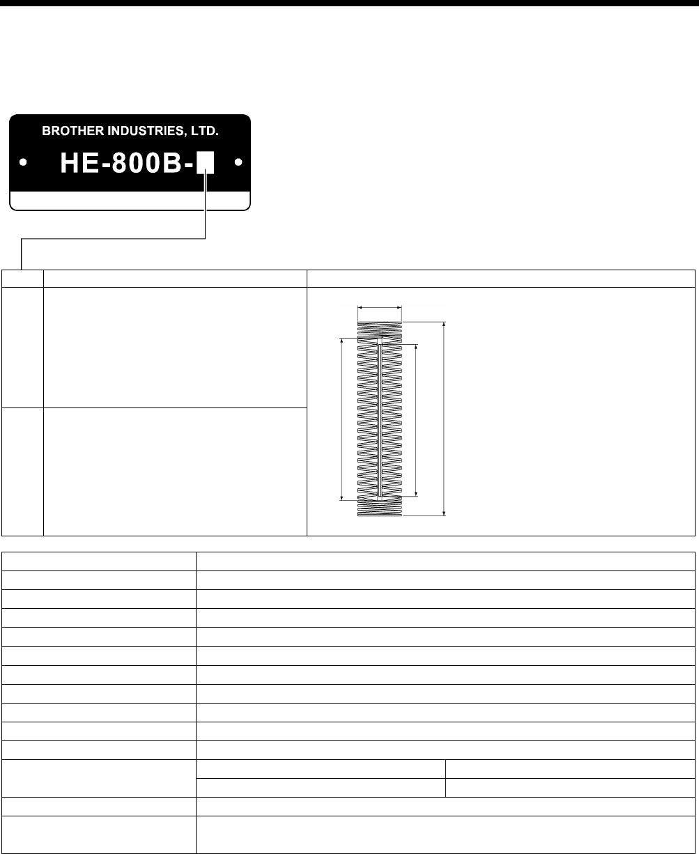
Main use
Buttonhole size
2
Buttonholes for clothing such as dress shirts,
blouses, work clothes and women's clothes
A: Max.6 mm
B: Max. zigzag stitch length 36 mm
C: Length of the hole 4 – 32 mm
D: Max. buttonhole length 40 mm
3
Buttonholes for knitted garments such as
knitted underwear, sweaters, cardigans and
jerseys
Max. sewing speed
4,000 sti/min
Zigzag mechanism
Pulse motor driven mechanism
Feed mechanism
Pulse motor driven mechanism
Work clamp lifter mechanism
Pulse motor driven mechanism
Height of work clamp
13 mm max. (adjustable)
Cutter drive method
Double position solenoid
Lower thread holding device
Standard equipment
Bobbin presser Standard equipment
Standard sewing pattern
21
Memory pattern
50
Max. number of stitch
999 stitches / program (Overall cycle program stitch no. 3,000 stitches)
Needle
-2
-3
Schmetz 134 Nm90
Schmetz 134 Nm75
Data recording media
SD memory card (No guarantees of operation can be given for any media.)
Power supply Single-phase 100V / 220V, 3-phase 220V / 380V / 400V
(For single-phase 100 V and three-phase 380 V/400 V, the trans box is required.)
2193Q
C D
A
B
4734M
HE-800B
1. SPECIFICATIONS
2
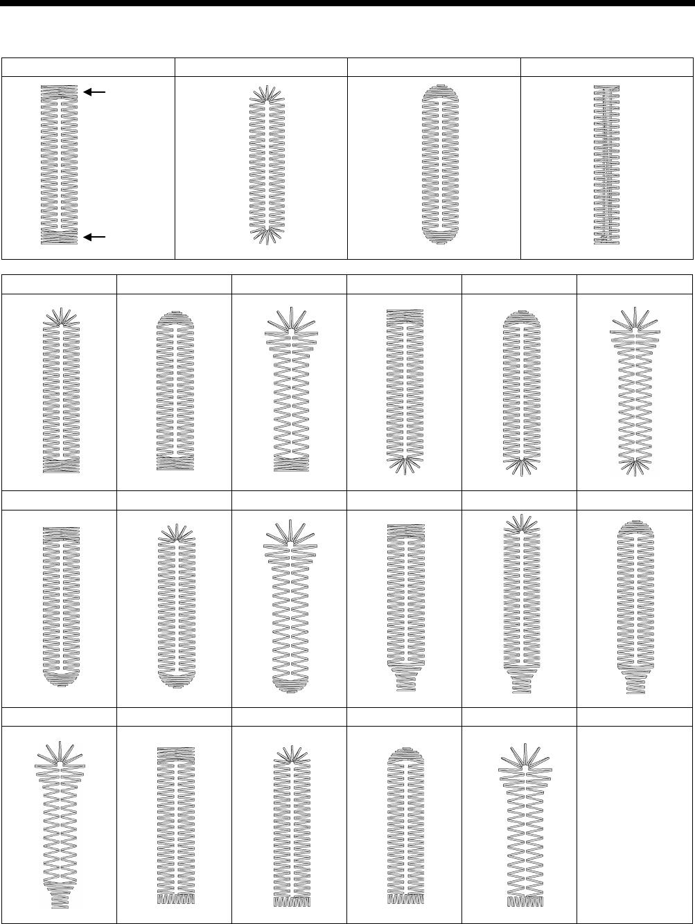
1-2. Standard sewing pattern list
Rectangle
Radial
Round
Straight bar tack
Radial-rectangle
Round-rectangle
Eyelet-rectangle
Rectangle-radial
Round-radial
Eyelet-radial
Rectangle-round
Radial-round
Eyelet-round
Rectangle-taper tack
Radial-taper tack
Round-taper tack
Eyelet-taper tack
Rectangle-tack
Radial-tack
Round-tack
Eyelet-tack
Rear tack
Front tack
2. NOTES ON HANDLING
HE-800B
3
2. NOTES ON HANDLING
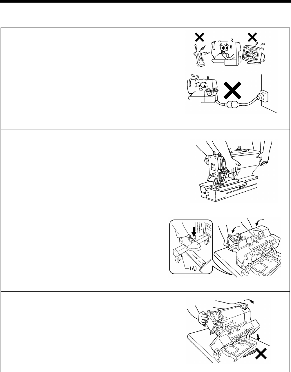
About the machine set-up location
・ Do not set up this sewing machine near other equipment
such as televisions, radios or cordless telephones,
otherwise such equipment may be affected by electronic
interference from the sewing machine.
・ The sewing machine should be plugged directly into an AC wall
outlet. Operation problems may result if extension cords are
used.
Carrying the machine
・ The machine should be carried by the arm by two people as
shown in the illustration.
Tilting back the machine head
1. Pack away any tools which are near the table.
2. Secure the foot (A) so that the table will not move, and then pull
the arm with both hands to tilt back the machine head.
* While supporting the arm with both hands, gently lower it.
Returning the machine head to the upright position
1. Pack away any tools which are near the table.
2. While supporting the arm with both hands, gently return the
machine head to its original position.
2516B
0597B
0598D
0599D
HE-800B
3. FUNCTION SETTINGS
4
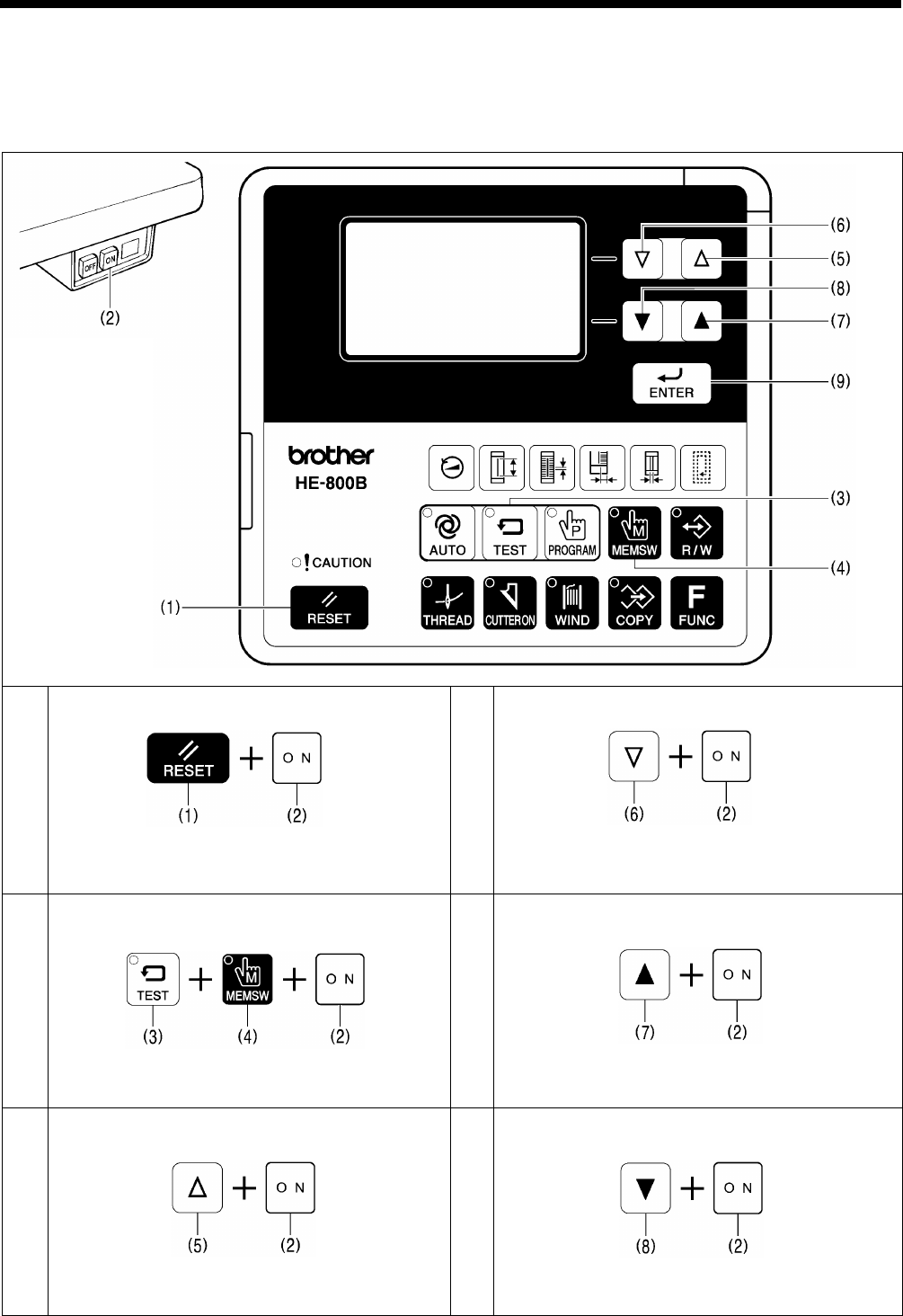
3. FUNCTION SETTINGS
3-1. List of special functions when power is turned on
This list shows the key operations for using special functions.
1
Data initialization function
Refer to the CD Instruction Manual.
4
Output check function
Refer to “3-8. Output checking method”.
2
Memory switch setting mode (Advanced)
Refer to “3-3. Setting memory switches (Advanced)”.
5
Software version display function
Refer to “3-9. Confirming software version”.
3
Input check function
Refer to “3-7. Input checking method”.
6
Error log display function
Refer to “3-6. Checking the error history”.
2593B
0600D
0601D
0604D
0602D
0605D
0603D
0606D
HE-800B
3. FUNCTION SETTINGS
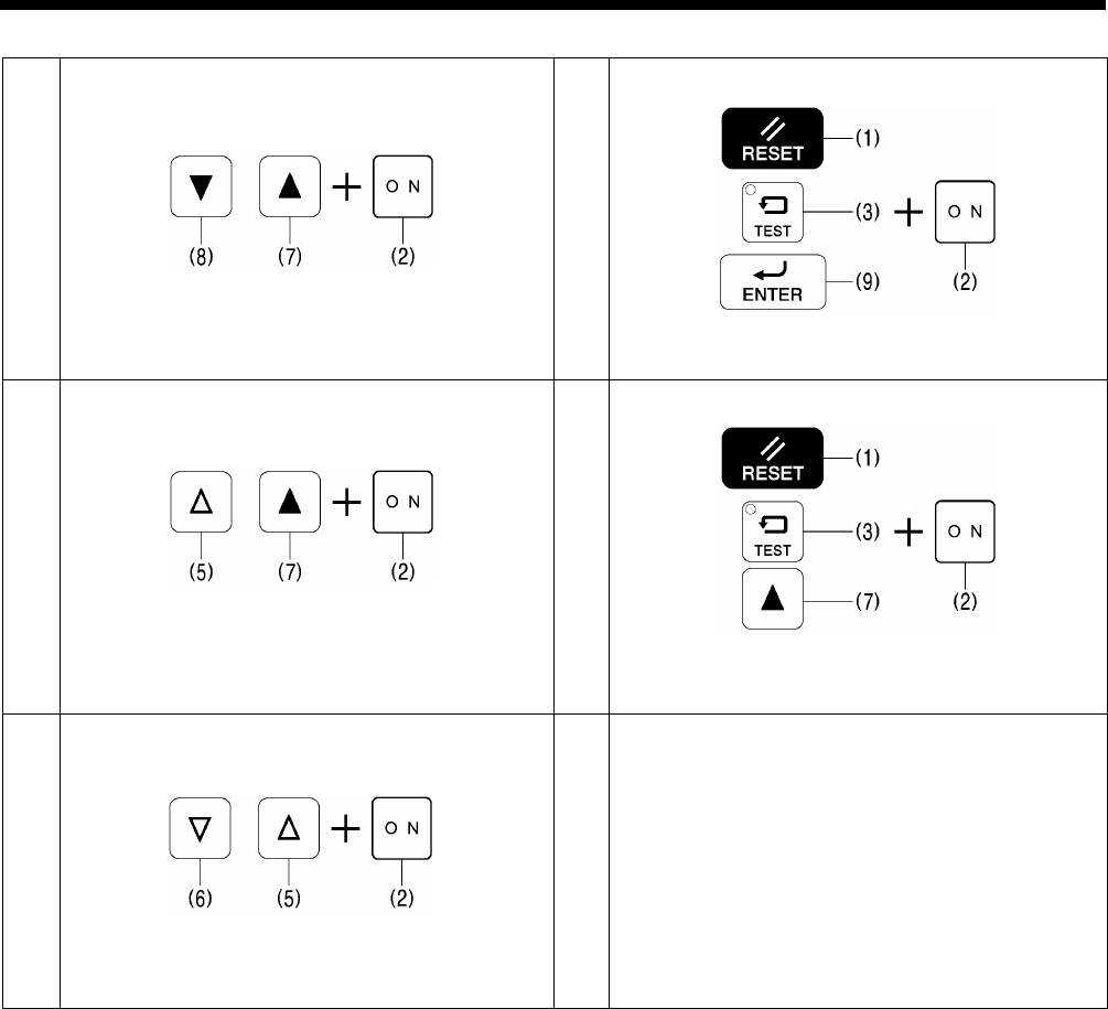
5
7
Home position adjusting mode
Refer to “7-2. Adjusting the home position”.
10
Protect setting mode
Refer to “3-10. Protection settings”.
8
Treadle position adjustment mode
Refer to “7-22.
Standard settings for treadle
depression stroke”.
11
Version update
Refer to “4-11. Updating the control program version”.
9
Upper shaft motor standard position
adjustment mode
Refer to “7-20
. Adjusting the upper shaft motor
reference position”.
0607D
0610D
0608D
0611D
0609D
HE-800B
3. FUNCTION SETTINGS
6
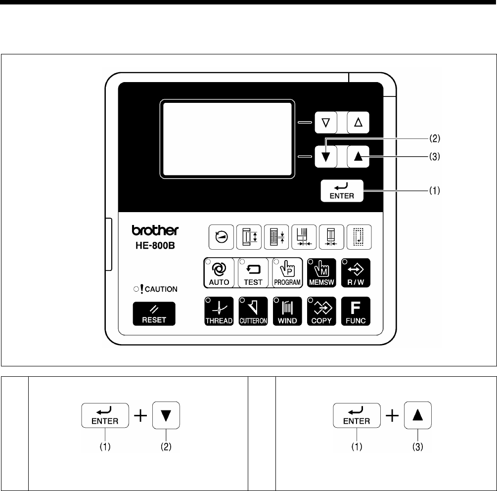
3-2. List of advanced functions
This list shows the key operations for using advanced functions.
1
Lower thread counter setting mode
Refer to the CD Instruction Manual.
2
Production counter setting mode
Refer to the CD Instruction Manual.
0612D
0613D
0614D
HE-800B
3. FUNCTION SETTINGS
7
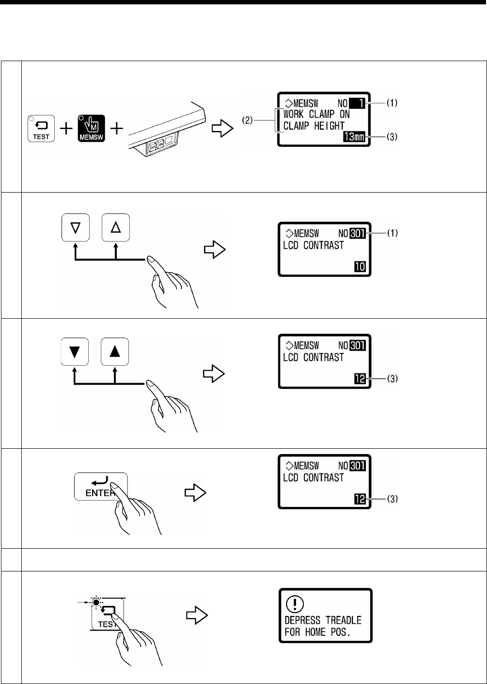
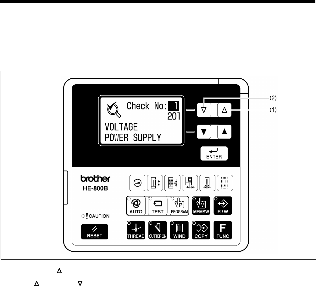
3-3. Setting memory switches (Advanced)
The settings for the memory switches are valid for all programs.
Refer to “3-4. List of memory switch” for details on memory switch Nos. and settings.
1
While pressing the TEST and MEMSW keys, turn on the power switch.
(1) Memory switch number
(2) Setting for selected number
(3) Setting range
2
Select the memory switch (1) that you would like to change the setting for.
3
Change the setting value (3).
• When the setting value is changed, (3) will start flashing.
• If you would like to return the setting to the default value,
press the RESET key.
4
Apply the changed setting.
The setting for the memory switch will be stored and (3) will
stop flashing and illuminate steadily.
5
To change the settings for other memory switch Nos., repeat the operations in steps 2 to 4 above.
6
Press the TEST key to exit memory switch mode.
Normal sewing machine operation will then be possible.
4787M
4792M
4857M
Flashing
0615D
4923M
4924M
4925M
4925M
4917M
4794M

HE-800B
3. FUNCTION SETTINGS
8
3-4. List of memory switches
NOTE:
In standard memory switch setting mode (refer to the CD instruction manual), the bottom two digits only display memory
switch Nos. 00 to 49.
To make the bottom two digits display memory switch Nos. 50 to 99, switch the sewing machine to Administrator memory
switch setting mode. (Refer to the previous page.)
Work clamp setting (001 to 099)
No.
Setting items
Setting range
Default value
001
Work clamp height when treadle is depressed.
Settings can be made in units of 1 mm.
1 to 13
13
002
Work clamp height when treadle is at neutral position.
Settings can be made in units of 1 mm.
1 to 13
10
003
Work clamp operation when treadle is depressed to the 1st step.
*
When using a triple pedal (optional part), this number will not be
displayed.
1: Work clamp does not drop to intermediate position.
2: Work clamp drops to intermediate position.
1 to 2
1
004
Work clamp height (mm) when dropped to intermediate position.
* Displayed when No. 003 above is set to “2”.
Settings can be made in units of 0.1 mm.
0.1 to 8.0
1.0
050
*1
Sewing machine starting procedure (pedal type).
1: Treadle.
3: Triple pedal.
1,3
1
052
Pausing enabled during automatic sewing when treadle is depressed backward.
*
When using a triple pedal (optional part), this number will not be
displayed.
OFF: Pausing is not allowed.
ON: Pausing is allowed.
ON/OFF
OFF
053
Work clamp operation when using a triple pedal.
* When using a treadle, this number will not be displayed.
(Refer to P. 15.)
* Neutral indicates that the work clamp is at the neutral position.
1: Remains lowered even when the work clamp switch is released, intermediate
lowering disabled, and starting prohibited when at neutral.
2: Remains lowered even when the work clamp switch is released, intermediate
lowering enabled, and starting prohibited when at neutral.
3: Remains lowered even when the work clamp switch is released, intermediate
lowering disabled, and starting allowed when at neutral.
4: Remains lowered even when the work clamp switch is released, intermediate
lowering enabled, and starting allowed when at neutral.
5: Returns to neutral when the work clamp switch is released, intermediate
lowering disabled, and starting prohibited when at neutral.
6: Returns to neutral when the work clamp switch is released, intermediate
lowering enabled, and starting prohibited when at neutral.
7: Returns to neutral when the work clamp switch is released, intermediate
lowering disabled, and starting allowed when at neutral.
8: Returns to neutral when the work clamp switch is released, intermediate
lowering enabled, and starting allowed when at neutral.
1 to 8
1
*1 This is not initialized during initialization mode. Also not overwritten from SD card.

HE-800B
3. FUNCTION SETTINGS
9
No.
Setting items
Setting range
Default value
055
Work clamp operation after automatic sewing is finished.
OFF: Work clamp remains lowered after automatic sewing is finished.
To raise the work clamp, carry out the following operations.
(A) For treadle: Depress the treadle backward.
(B) For triple pedal: Press the work clamp lifter switch.
ON: Work clamp remains raised after automatic sewing is finished.
ON/OFF
ON
060
Work clamp lifting speed.
-: Lifting speed becomes slower.
+: Lifting speed becomes faster.
-4 to 4
0
061
Work clamp lowering speed.
-: Dropping speed becomes slower.
+: Dropping speed becomes faster.
-4 to 4
0
062
Thread trimming speed.
-: Thread trimming speed becomes slower.
+: Thread trimming speed becomes faster.
-4 to 4
0
Sewing machine motor settings (100 to 199)
No.
Setting items
Setting range
Default value
150
Automatic needle lifter operation ON/OFF.
OFF: If the pulley is at the needle up stop position during needle bar and work
clamp home position detection, a needle up error will be generated.
ON: If the pulley is not at the needle up stop position during needle bar and
work clamp home position
detection, it will move automatically to the
needle up stop position, and then home position detection will be carried
out.
ON/OFF
ON
151
Needle up stop position correction.
Setting can be carried out in units of 1°.
-: Stopping position becomes earlier.
+: Stopping position becomes later.
-7 to 7
0

HE-800B
3. FUNCTION SETTINGS
10
Feed mechanism (200 to 299)
No.
Setting items
Setting range
Default value
250
Automatic upper shaft deceleration to emphasize feeding.
OFF: Normal.
ON: The proportional feed time for each stitch is
reduced from normal in
order to prevent needle deflection with heavy materials.
* This may limit the upper shaft speed.
ON/OFF
OFF
251
Feed timing correction.
Setting can be carried out in units of 1°.
-: Feed timing is advanced in relation to the upper shaft phase.
+: Feed timing is retarded in relation to the upper shaft phase.
-20 to 20
0
252
*1
Home position detection method after power is turned on.
1: Home position detection is carried out by pedal operation.
2: Home position detection is carried out by pressing the RESET key.
1 to 2
1
*1 This is not initialized during initialization mode. Also not overwritten from SD card.
Operation panel settings (300 to 399)
No.
Setting items
Setting range
Default value
300
Parameter number assignment for FUNC key.
Functions can be assigned to the FUNC key to make it operate as a seventh
shortcut key.
OFF: No assignment.
(The help screen is displayed while the FUNC key is pressed.)
1 to 60: When the FUNC key is pressed, the parameter setting screen for the
number which has been set is displayed.
OFF, 1 to 60
OFF
301
Display screen contrast.
You can change the degree of contrast.
The higher the number, the stronger the contrast.
1 to 15
10
302
Counter display during automatic sewing mode.
The contents
appearing at (1) in the display during automatic sewing mode
can be set to either the lower thread counter display or the production counter
display.
1: Lower thread counter
2: Production counter
1 to 2
1
350
Production counter operation by cycle sewing units during cycle sewing.
OFF: Counts in units of individual programs (1 hole).
ON: Counts in units of individual cycle programs.
ON/OFF
OFF
4926M

HE-800B
3. FUNCTION SETTINGS
11
User program settings (400 to 499)
No.
Setting items
Setting range
Default value
450
Maximum sewing speed.
Setting can be carried out in units of 100 (sti/min).
* When setting the sewing speed, the speed will be limited by this value.
1000 to 4000
4000
451
Maximum number of cycle programs.
This lets you set the number of cycle programs that can be used.
* If you do not want cycle programs to be displayed, set to “0”.
0 to 9
9
Device settings (500 to 599)
No.
Setting items
Setting range
Default value
550
Cutter power.
The larger the value, the stronger the cutting force.
1 to 6
3
551
Cutter home position error checking.
OFF:
Error checking is not carried out (emergency measures when there is a
sensor problem).
ON: Error checking enabled.
ON/OFF
ON
552
Upper thread tightening when sewing underlays.
OFF: Upper thread is not tightened.
ON: Upper thread is tightened.
ON/OFF
OFF
554
Using the thread breakage detector.
OFF: Thread breakage detector is not used.
ON: Thread breakage detector is used.
ON/OFF
ON
555
Number of stitches before upper thread breakage is detected.
* Displayed when No. 554 above is set to “ON”.
Upper thread breakage detection starts after the set number of stitches has
been sewn.
1 to 10
10
556
Number of stitches for upper thread breakage judgment.
* Displayed when No. 554 above is set to “ON”.
An
upper thread breakage error occurs when the upper thread breakage
signal is continuously ON for the set number of stitches.
2 to 7
5

HE-800B
3. FUNCTION SETTINGS
12
Error processing settings (600 to 699)
No.
Setting items
Setting range
Default value
650
Time from error occurring to buzzer stopping.
OFF: Buzzer does not stop.
2 to 30: Buzzer stops after the specified time (set in units of 2 seconds).
OFF, 2 to 30
OFF
651
Needle zigzag and feed motor energization status when a non-resettable error
occurs.
OFF: Needle zigzag and feed motor energization is turned off.
ON: Needle zigzag and feed motor energization remains on.
ON/OFF
OFF
652
Needle zigzag motor status when a pause or thread breakage occurs during
automatic sewing.
OFF: Needle zigzag motor energization is turned off.
ON: Needle zigzag motor energization remains on.
ON/OFF
ON
Maintenance settings (700 to 799)
No.
Setting items
Setting range
Default value
700
Y cutting position (feed direction) correction.
The cutter position for the sewing pattern can be
corrected in the Y (feed) direction.
Settings can be made in units of 0.025 mm.
When + is selected, the cutting position moves
further to the back.
-0.800 to
0.800
0
750
Continuous sewing permission (for administrator).
OFF: Disabled (Continuous sewing forbidden).
ON: Sewing operation is repeated while the treadle is being depressed to
2nd step.
NOTE:
This setting is test operation mode for use by an administrator.
It is
dangerous to set it to ON while sewing, so be sure to set it back to
OFF after use.
ON/OFF
OFF
751
Continuous sewing interval (for administrator).
* Displayed when No. 750 above is set to “ON”.
Setting can be carried out in units of 100 ms.
0 to 2500
1000
752
Sewing machine ID code (for specifying SD card folder)
0 to 99
0
755
Thread winding speed limit.
OFF: Upper limit is not limited to 2000 sti/min.
*
Thread winding is carried out at the speed specified at the operation panel.
ON: Upper limit is limited to 2000 sti/min.
*
If the speed specified at the operation panel exceeds 2000 sti/min, thread
winding will be limited to 2000 sti/min.
ON/OFF
ON
Forward
1445Q
Back
HE-800B
3. FUNCTION SETTINGS
13
Specification and destination settings (800 to 899)
No.
Setting items
Setting range
Default value
850
*1
Machine head specifications
2: -2 specifications (for cotton and silk)
3: -3 specifications (for knitted materials)
2,3
-2 specifications:
2
-3 specifications:
3
*2
851
*1
Sewing area(Work clamp size) *4
Sewing area Work clamp size
1: 4.0 x 15.0mm 5.4 x 19.0mm
2: 4.0 x 20.0mm 5.4 x 24.5mm
3: 4.0 x 32.0mm 5.4 x 36.0mm
4: 5.4 x 20.0mm 6.8 x 24.5mm
5: 5.4 x 32.0mm 6.8 x 36.0mm
6: 5.4 x 40.0mm 6.8 x 47.0mm
7: 6.0 x 20.0mm 7.3 x 24.5mm
8: 6.0 x 32.0mm 7.3 x 36.0mm
9: 6.0 x 40.0mm
7.3 x 47.0mm
1 to 9
3
852
*1
Max. needle zigzag feed width(Needle plate size) *4
4: 4mm(5.4mm)
6: 6mm(7.3mm)
4,6
-2 specifications:
6
-3 specifications:
4
*2
853
*1
Language
0: English
1: Japanese
2: Chinese
0 to 2
China: 2
Europe: 0
Other: 0
*3
*1 This is not initialized during initialization mode. Also not overwritten from SD card.
*2 The initial value is determined by the machine head specifications at the time of shipment from the factory.
*3 The initial value is determined by the shipping destination at the time of shipment from the factory.
*4 The actual sewing area is determined by the work clamp dimensions and the needle plate dimensions.
Needle plate size
5.4mm 7.3mm
Work clamp size
(Width x Length)
5.4 x 19.0mm 4.0 x 15.0mm 4.0 x 15.0mm
5.4 x 24.5mm 4.0 x 20.0mm 4.0 x 20.0mm
5.4 x 36.0mm 4.0 x 32.0mm 4.0 x 32.0mm
6.8 x 24.5mm 4.0 x 20.0mm 5.4 x 20.0mm
6.8 x 36.0mm 4.0 x 32.0mm 5.4 x 32.0mm
6.8 x 47.0mm 4.0 x 40.0mm 5.4 x 40.0mm
7.3 x 24.5mm 4.0 x 20.0mm 6.0 x 20.0mm
7.3 x 36.0mm 4.0 x 32.0mm 6.0 x 32.0mm
7.3 x 47.0mm 4.0 x 40.0mm 6.0 x 40.0mm
HE-800B
3. FUNCTION SETTINGS
14
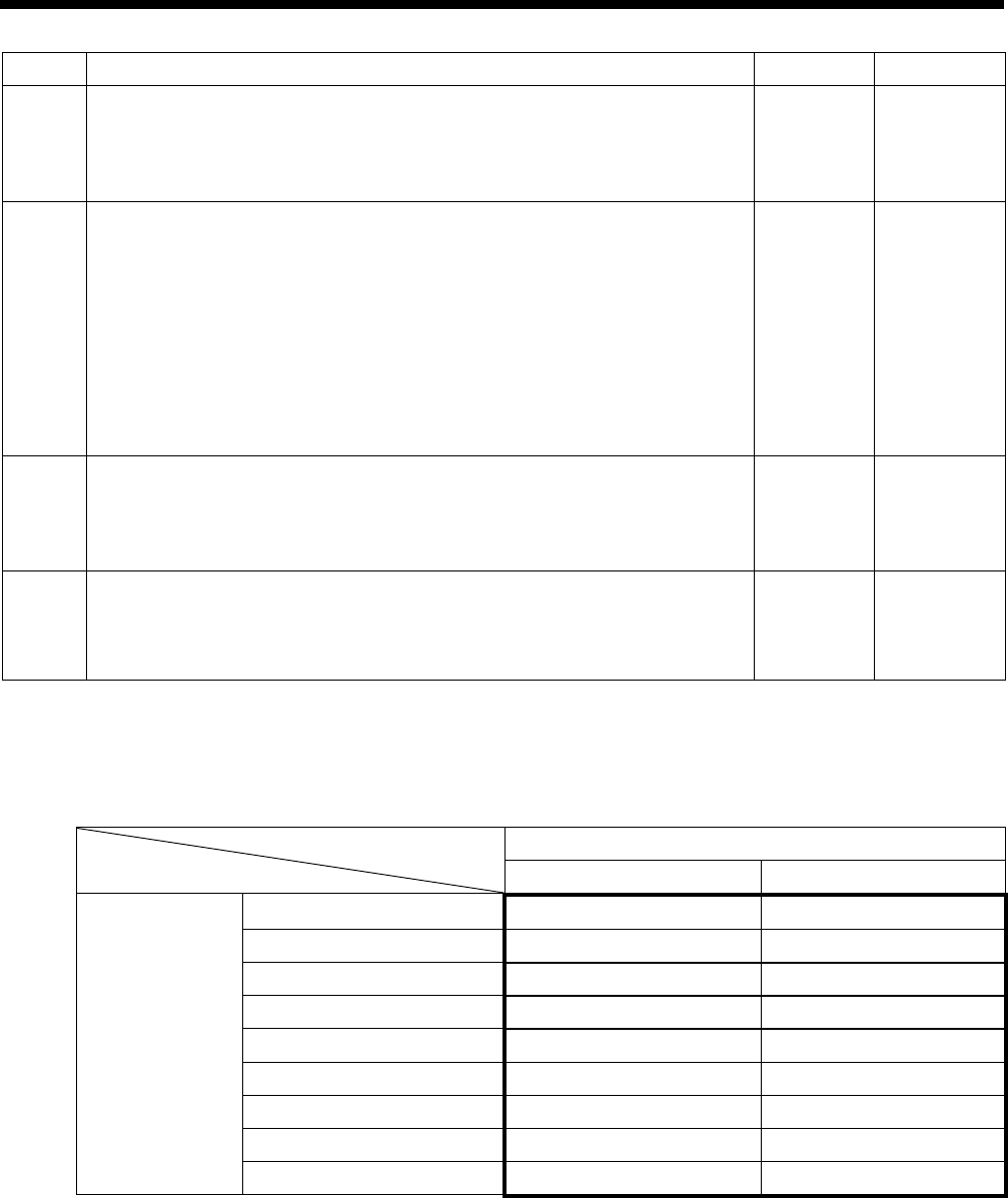
3-5. Pedal operation mode setting method
When using the treadle
The following table describes the operation of the work clamp during sewing standby mode when using the treadle.
1. Set memory switch No. 050 to “1”.
2. Use memory switch No. 003 to select the desired operation mode from the following.
Setting
value
No.003
Treadle
Depressed
backward
Neutral
1st step
2nd step
1 Work clamp
raised
Work clamp
neutral
position
Work clamp
maximum
drop
Sewing
machine
start
2 Work clamp
raised
Work clamp
neutral
position
Work clamp
intermediate
drop
Work clamp
maximum drop
+ sewing
machine start
Raised
Depressed
further
Releas
Depres
1st step
Neutral
1st step
2nd step
Depress
backward
Release
1
st step
2
nd step
Neutral
Depressed
Insertion and removal of the
material
Normal position Sewing
Buttonhole positioning
Neutral Maximum drop
Intermediate drop
After sewing
0796D
Neutral
Depressed
HE-800B
3. FUNCTION SETTINGS
15
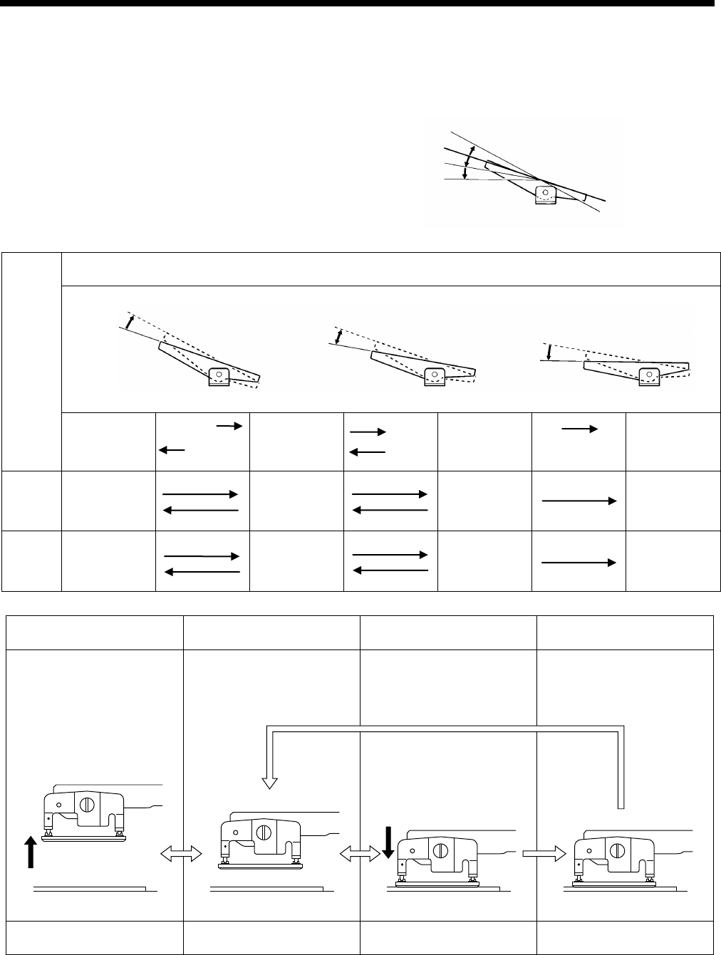
When using a triple pedal (option)
The following table describes the operation of the work clamp during sewing standby mode when using a triple pedal.
1. Set memory switch No. 050 to “3”.
2. Use memory switch No. 053 to select the desired operation mode from the following.
Setting
value
No. 053
Work clamp
lifter switch
Release →
← Depress All switches OFF Depress →
← Release Work clamp switch Start switch
1 Work clamp
lifts
Work clamp
neutral position
Work clamp neutral
position
Sewing
machine starts
2 Work clamp
lifts
Work clamp
neutral position
Work clamp neutral
position
Work clamp maximum
drop
+
Sewing
machine starts
3 Work clamp
lifts
Work clamp neutral
position
(Work clamp
maximum drop)
+
Sewing
machine starts
4 Work clamp
lifts
Work clamp neutral
position
Work clamp maximum
drop
+
Sewing
machine starts
5 Work clamp
lifts
Work clamp
neutral position
Sewing
machine starts
6 Work clamp
lifts
Work clamp
neutral position
Work clamp maximum
drop
+
Sewing
machine starts
7 Work clamp
lifts
(Work clamp
maximum drop)
+
Sewing
machine starts
8 Work clamp
lifts
Work clamp maximum
drop
+
Sewing
machine starts
* The start switch is enabled at statuses indicated by .
Work clamp switch
Work clamp lifter switch
Start switch
Work clamp
neutral position
Work clamp
neutral position
Work clamp
neutral position
Work clamp
maximum drop
Work clamp
maximum drop
Work clamp
intermediate drop
Work clamp
neutral position
Work clamp
intermediate drop
Work clamp
maximum drop
Work clamp
intermediate drop
Work clamp
maximum drop
Work clamp
intermediate drop
Work clamp
maximum drop
Work clamp
intermediate drop
Work clamp
maximum drop
Work clamp
intermediate drop
0770D
HE-800B
3. FUNCTION SETTINGS
16
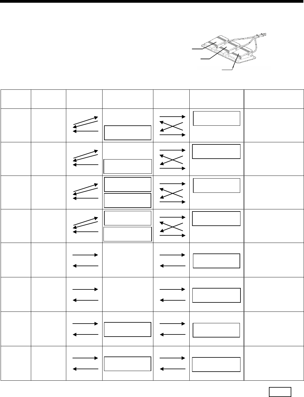
3-6. Checking the error history
The past error history can be checked by the following procedure.
1. While pressing the key (1), turn on the power switch.
Error history numbers, error codes and production counter values (lower 6 digits) will be displayed on the screen.
NOTE:
E025, E035, E045, E065, E705 and error codes which can be reset do not remain in the error history, and so they will
not be displayed.
2. Press the or key (2) to switch the error history sequentially.
Up to 96 histories (01 to 96) are stored in order starting from the newest. No. 01 represents the newest error.
(If there are no error codes, “E---” will be displayed.)
While the FUNC key (3) is being pressed, the error codes will be removed from the display and the production counter
when the error occurred will be displayed as 10 digits.
3. Press the TEST key (4) to return to the normal display. The sewing machine will switch to home position detection
standby.
0618D
HE-800B
3. FUNCTION SETTINGS
17
3-7. Input checking method
This is used at the following times.
・ When you would like to check for problems with the operation panel.
・ When you would like to check for broken cords.
・ When you would like to adjust a sensor position.
This lets you check if the CPU is reading signals from the keys and the sensors correctly.
1. While pressing the key (1), turn on the power switch.
Item numbers, item names and input statuses will be displayed on the screen.
2. Press the key (1) or the key (2) to select the desired item number.
3. Refer to the input check list to check the key and sensor responses.
4. When returning to normal operation, turn power off and then on again.
0799D
HE-800B
3. FUNCTION SETTINGS
18
<Input check list>
Item No.
Input status
Check item and checking method
1
***
Shows the input voltage.
2 ON/OFF
X (needle zigzag) axis motor home position sensor position.
Move the needle bar manually.
Turns ON when moved to the left.
3 ***
X (needle zigzag) axis motor encoder counter value.
Move the needle bar manually.
Goes down when moved to the left.
* When the power is turned on, the position will be “0”.
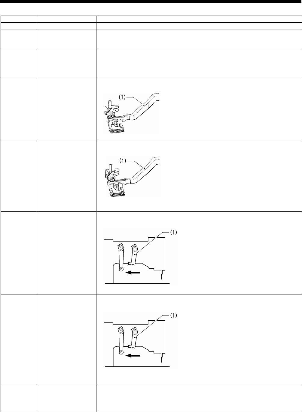
4 ON/OFF
Y (feed) axis motor home position sensor position.
Move the feed arm (1) manually.
Turns on when moved to the inside.
5 ***
Y (feed) axis motor encoder counter value.
Move the feed arm (1) manually.
Goes down when moved to the inside.
* When the power is turned on, the position will be “0”.
6 ON/OFF
Work clamp motor home position sensor position.
Move the trimmer driving arm (1) manually.
Turns on when moved in the direction of the arrow.
7 ***
Work clamp motor encoder counter value.
Move the trimmer driving arm (1) manually.
Goes down when moved in the direction of the arrow.
* When the power is turned on, the position will be “0”.
8 0 to 255
Treadle analog value.
Depress the treadle.
When depressed forward, the value increases.
* Should normally display somewhere around 109 when at the neutral position.
0771D
0771D
1770B
1770B
HE-800B
3. FUNCTION SETTINGS
19
9 ON/OFF
Work clamp lifter switch.
Turns on when the work clamp lifter switch of the triple pedal (option) is pressed.
10 ON/OFF
Work clamp switch.
Turns on when the work clamp switch of the triple pedal (option) is pressed.
11 ON/OFF
Start switch.
Turns on when the start switch of the triple pedal (option) is pressed.
12 ON/OFF
STOP switch connection signal.
Turns off when the STOP switch is not connected.
13 ON/OFF
STOP switch.
Turns on when the STOP switch is pressed.
14 ON/OFF
Safety switch.
Turns off when the machine head is tilted back.
15 ON/OFF
Cutter home position sensor.
Turns off when the cutter is pushed down by hand.
16 ON/OFF
Upper thread breakage detection signal.
Turns off when the upper thread breakage detection guide is moved to the right.
19 ON/OFF
Needle up signal.
Turn the pulley by hand.
* ON in the needle up region, OFF in any other region.
20 0 to 359
Upper shaft 360 degree rotation signal.
Turn the pulley by hand.
* Increases when turned forward (counterclockwise
rotation).
21
ON/OFF
key.
22
ON/OFF
key.
23
ON/OFF
ENTER key.
24
ON/OFF
Shortcut 1 key.
25
ON/OFF
Shortcut 2 key.
26
ON/OFF
Shortcut 3 key.
27
ON/OFF
Shortcut 4 key.
28
ON/OFF
Shortcut 5 key.
29
ON/OFF
Shortcut 6 key.
30
ON/OFF
AUTO key.
31
ON/OFF
TEST key.
32
ON/OFF
PROGRAM key.
33
ON/OFF
MEMSW key.
34
ON/OFF
R/W ke y.
35
ON/OFF
RESET key.
36
ON/OFF
THREAD key.
37
ON/OFF
CUTTER ON key.
38
ON/OFF
WIND key.
39
ON/OFF
COPY key.
40
ON/OFF
FUNC key.
42
ON/OFF
Option input 2.
43
ON/OFF
Option input 3.
44
ON/OFF
Option input 4.
45
ON/OFF
Option input 5.
46
ON/OFF
Option input 6.
47
ON/OFF
Option input 7.
48
ON/OFF
Option input 8.
49
ON/OFF
Option input 9.
50
ON/OFF
Option input 10.
0783D
HE-800B
3. FUNCTION SETTINGS
20
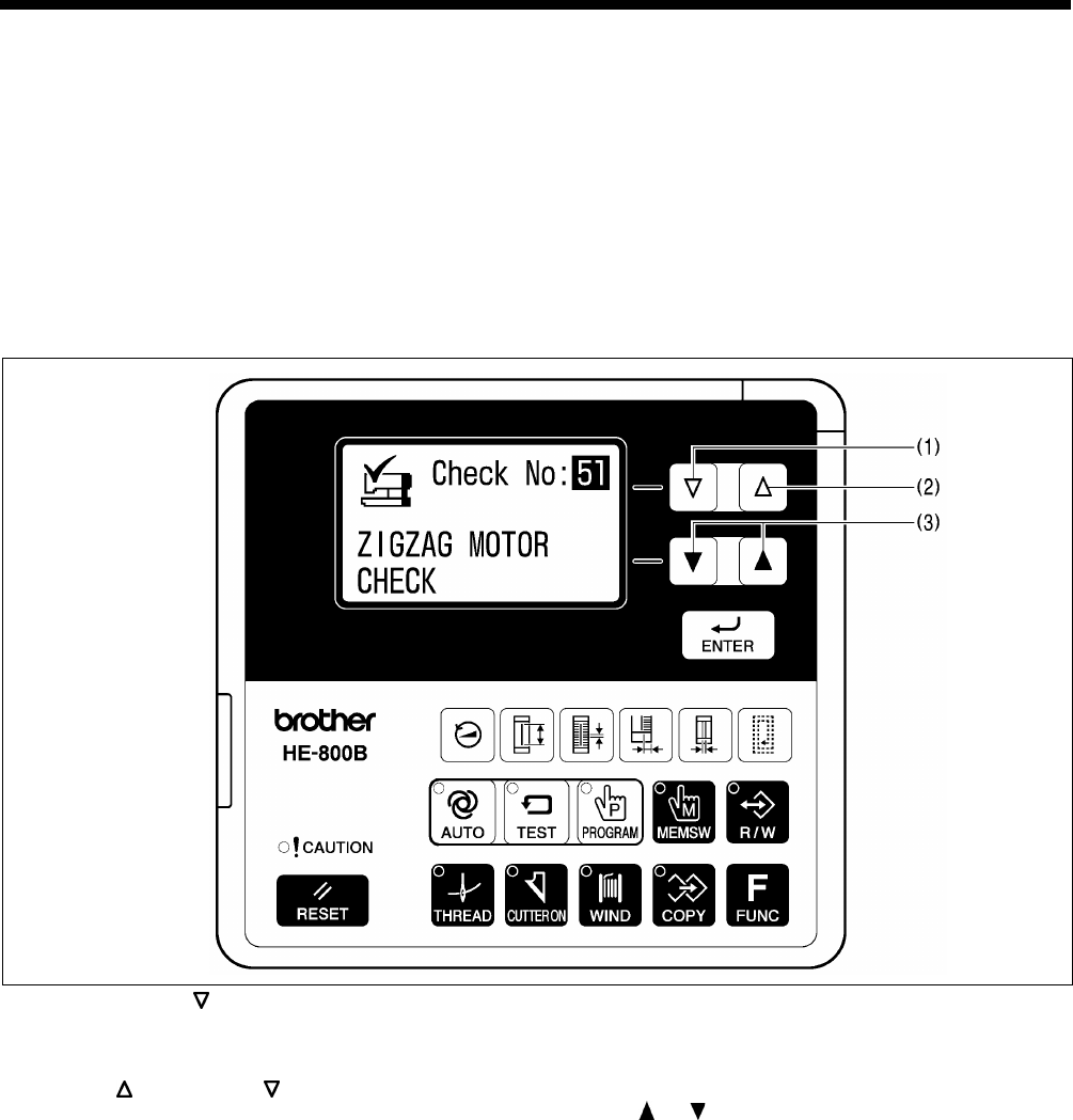
3-8. Output checking method
This is used at the following times.
・ When you would like to check for problems with the operation panel.
・ When you would like to check for a problem with the drive mechanism.
・ When you would like to check for broken cords.
You can check whether the signals being output by the CPU are driving the mechanisms correctly.
NOTE:
Carry out this procedure after checking that the input check is normal. If there are problems with the input signals, it may not
be possible to carry out an output check.
1. While pressing the key (1), turn on the power switch.
2. Depress the treadle to the 2nd step. (Start switch for a triple pedal)
The needle bar and the work clamp will move to the home position. Item numbers and item names will be displayed on the
screen.
3. Press the key (2) or the key (1) to select the desired item number.
4. The operations for item codes 51 to 53 can be checked by pressing the or key (3).
* The operation for that check item will be carried out while the key is being pressed.
5. For item numbers 54 and after, depress the treadle to the 2nd step. (Start switch for a triple pedal)
* The operation for the item being checked will be carried out while the treadle is being depressed.
6. When returning to normal operation, turn power off and then on again.
0800D

HE-800B
3. FUNCTION SETTINGS
21
Item No.
Operation
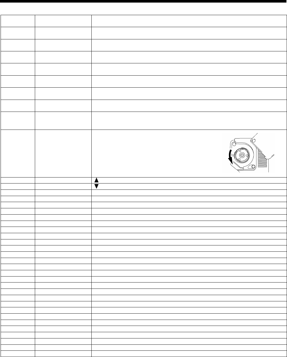
51
When the and keys are pressed, the needle bar will move in units of 1 mm.
: Needle bar moves to the right (+).
: Needle bar moves to the left (-).
52
When the and keys are pressed, the work clamp will move in units of 0.1 mm.
: Work clamp moves to the front (+).
: Work clamp moves to the back (-).
53
When the and keys are pressed, the work clamp will move in units of 0.12 mm.
: Work clamp moves up (+).
: Work clamp moves down (-).
At this time, upper thread trimming and lower thread trimming are carried out in conjunction with the
operation of the work clamp.
54
The buzzer will sound for 0.7 second, and then the sewing machine will start (at the longest for 1 minute).
Immediately after the motor stops, the upper shaft angle (normally around 55) will be displayed.
While the motor is stopped, you can press the and keys to change the speed (between 1000 sti/min
and 4000 sti/min).
55
The buzzer will sound for 0.7 second, then the work clamp will move 15 mm back and forth, and then the
cutter will operate.
56
The tension release solenoid will turn on.
57
The panel indicators will illuminate in order.
CAUTION → AUTO → TEST → . . . . → COPY
58
The buzzer will sound.
59
Option output 1 will turn on.
60
Option output 2 will turn on.
61
Option output 3 will turn on.
62
Option output 4 will turn on.
63
Option output 5 will turn on.
64
Option output 6 will turn on.
65
Option output 7 will turn on.
66
Option output 8 will turn on.
67
Option output 9 will turn on.
68
Option output 10 will turn on.
69
Option output 11 will turn on.
70
Option output 12 will turn on.
71
Option output 13 will turn on.
72
Option output 14 will turn on.
73
Option output 15 will turn on.
74
Option output 16 will turn on.
75
Option output 17 will turn on.
76
Option output 18 will turn on.
77
Option output 19 will turn on.
78
Option output 20 will turn on.
HE-800B
3. FUNCTION SETTINGS
22
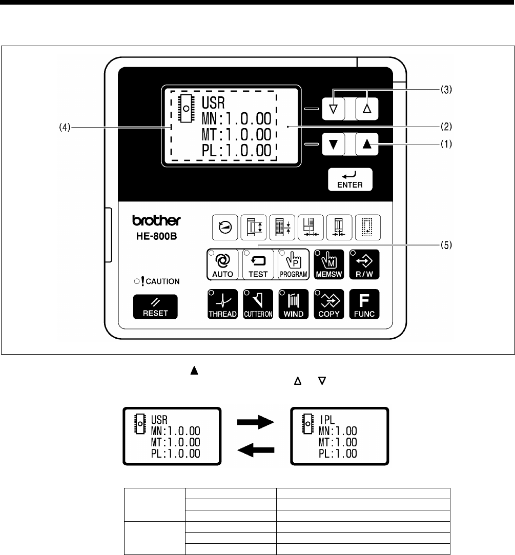
3-9. Confirming software version
1. If you turn on the power while pressing the key (1), the software version will be displayed in the menu display (2).
2. The PROGRAM No. display (4) will change as follows each time the or key (3) is pressed.
USR
MN
Main control program
MT
Motor control program
PL
Panel control program
IPL
MN
Main IPL
MT
Motor IPL
PL
Panel IPL
3. Press the TEST key (5) to return to the normal display. The sewing machine will switch to home position detection
standby.
0621D
0622D
HE-800B
3. FUNCTION SETTINGS
23
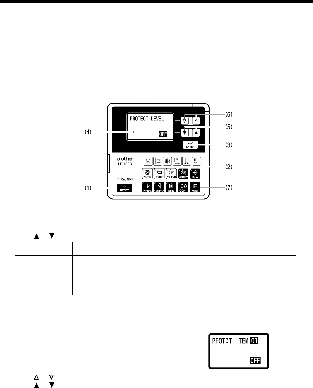
3-10. Protection settings
There are two ways which can be used to switch to protect setting mode: Method A (which does not require an SD card) and
Method B (which requires an SD card).
If you want to set up the sewing machine so that these modes cannot be distinguished, it is recommended that you set the
method to Method B.
* If using an SD card, read the section titled “4-1. Notes on handling SD cards (commercially available)”.
Method A
1. While pressing the RESET key (1) and the TEST key (2) and the ENTER key (3), turn on the power switch.
* The previous protection level (OFF, 1 to 5) will appear in the menu display (4).
* The protection level is set to OFF at the time of shipment from the factory.
* If a beeping sound is heard and “Wrong Starting” is displayed, it means that the method has been set to “Method B”.
In this case, start by means of method B. (Refer to the next page.)
2. Press the or key (5) to select the protection level.
Protection level
Details
OFF
Nothing is disallowed.
1 to 4
Certain operations are disallowed depending on the protection level.
*
Protected items have been preset for each level. Refer to “Table of protection
levels and corresponding protected items” on page 25.
5
You can set the protection level for each of the 11 items individually.
* Set to ON (disallowed) or OFF (allowed) for each item.
* All items are set to OFF at the time of shipment from the factory.
3. Press the ENTER key (3) to store the protection level.
* If setting to a protection level other than level 5, proceed to step 4. If setting to level 5, proceed to step 5.
4. Press the TEST key (2).
* The display will return to the normal display and the sewing machine will change to home position standby.
5. Item numbers and setting values (ON/OFF) will be displayed on the screen.
6. Press the or key (6) to select the item number (1 to 11). (Refer to page 25.)
7. Press the or key (5) to change the setting (ON/OFF).
8. Press the ENTER key (3) to store the setting (ON/OFF).
9. Repeat steps 6 to 8 above for each item, and then press the TEST key (2).
* The protect setting mode will be exited and the sewing machine will change to home position standby.
* To return to the protection level setting status (step 2 above), press the FUNC key (7).
0801D
0802D
HE-800B
3. FUNCTION SETTINGS
24
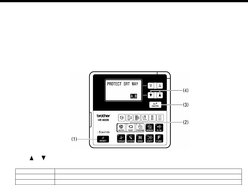
Method B
Have an SD card ready.
* The SD card is only used at the step of selecting protect setting mode, so any type of SD card can be used as long as it
can be accessed. In addition, if making the setting two or more times, a different SD card from the one used before can be
used.
1. Insert the SD card, and then while pressing the RESET key (1) and the TEST key (2) and the ENTER key (3), turn on the
power switch.
* The previous starting method (“A, B” or “B”) will appear in the menu display.
* The method is set to “A,B” at the time of shipment from the factory.
2. Press the or key (4) to select the next starting method.
Starting method
Details
A,B
Protect setting mode can be started using either Method A or Method B.
B
Protect setting mode can only be started using Method B.
3. Press the ENTER key (3) to store the starting method.
4. For the method of operation from this point onward, refer to steps 2 to 9 in “Method A” (previous page).
0803D

HE-800B
3. FUNCTION SETTINGS
25
Table of protection levels and corresponding protected items
× : Operation disallowed
Level
Setting items
OFF 1 2 3 4 5
1 2 3 4 5 6 7 8 9 10 11
Data initialization × × × × ×
Standard memory switch settings × × ×
Administrator memory switch settings
× × × ×
Changing the program number
× × × ×
Changing the sewing speed
(Parameters relating to sewing speed)
× × × × ×
Program editing × × × ×
Program copy mode × × × ×
Cutter operation × × × ×
Production counter editing × × ×
Lower thread counter editing
× × ×
Resewing after sewing is interrupted × × ×
Home position adjustment × ×
Upper shaft motor reference position
adjustment
× ×
Treadle position adjustment
× ×

4. USING SD CARDS
26
HE-800B
4. USING SD CARDS
4-1. Notes on handling SD cards (commercially available)
• Use an SD card or a multimedia card with a capacity of 2GB or less.
• Do not disassemble or alter SD cards.
• Do not bend, drop, scratch or place heavy objects on top of the SD cards.
• Do not allow the SD cards to become wet, such as with water, oil, solvents, drinks or any other liquids.
• Do not use or store the SD cards in a locations exposed to strong static electricity or electrical interference.
• Do not use or store the SD cards in a locations exposed to vibrations or impacts, direct sunlight, extreme dust (or lint), high
temperatures, high humidity, severe temperature fluctuations, or strong magnetic forces (such as from speakers).
• Do not subject the SD cards to vibration or shocks or remove them from the sewing machine while data reading or writing
is in progress.
• Data on the SD cards may be lost or damaged due to some malfunction or accident. We recommend backing up important
data.
• The SD cards that you purchased is already formatted. We recommend that the SD cards not be reformatted.
• The recommended SD cards are those sold by SanDisk and Panasonic. Cards from other manufacturers may use different
formatting methods and may not work correctly as a result.
For additional information, refer to the instruction manual included with the SD cards that you have purchased.
* This product is compatible with SD cards that have been formatted using the FAT16/32 method. Cards that have
been formatted using other formatting methods cannot be used.
* All other company and product names mentioned in this instruction manual are trademarks or registered trademarks
of their respective companies. However, the explanations for markings such as TM are not clearly described within
the text.
4-2. Structure of an SD card folder
Data type
Folder name
File name
Control program \BROTHER\ISM\ISMSYS\
ISM09MN.BVP (Main control program)
ISM09MT.BVP (Motor control program)
ISM09PL.BVP (Panel control program)
Program data
(parameters)
\BROTHER\ISM\ISMDH**\
*
‘**’ represents the value for memory switch No.
752. If program data from other sewing
machines in the same SD memory card,
change the name of the folder.
ISMUPG.SEW
memory switch
data Same as above ISMMSW.SEW
cycle program
data
Same as above ISMCYC.SEW
Error log data \BROTHER\ISM\ISMLDT\ Stores the files which relate to error logs.
4. USING SD CARDS
HE-800B
27
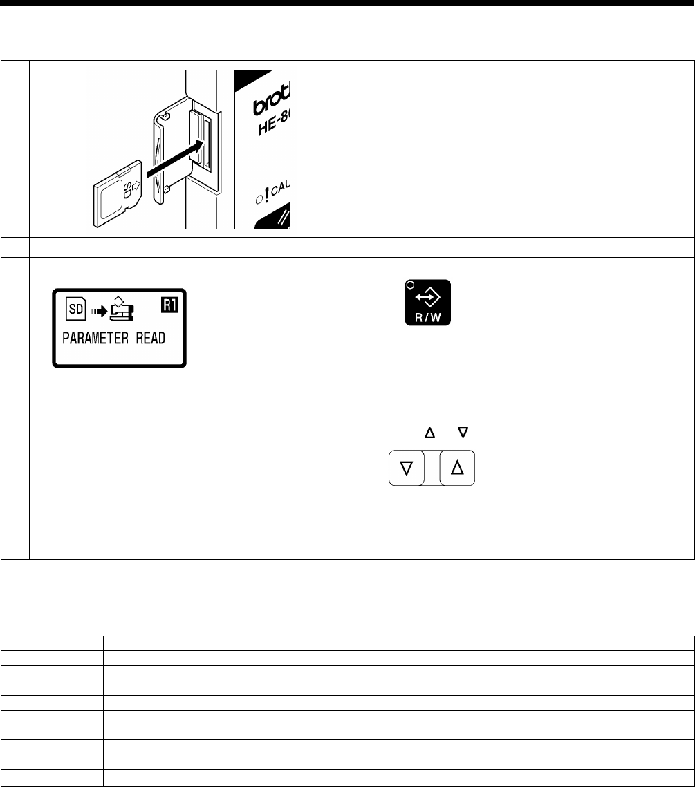
4-3. Preparation for reading and writing data
1
Insert the SD card into the SD slot.
NOTE:
• Make sure the SD card is facing the correct way.
•
The cover should be closed at all times except when
the SD card is inserted and removed, otherwise dust
may cause trouble
2
Turn on the power switch.
3
The mode will switch to data read/write mode.
Press the R/W key.
•
The R/W indicator will illuminate and the mode will
switch to data read/write mode.
• The initial status is parameter reading. (Refer to
“Read/write menu list” below.)
4
Select the read/write menu.
Press the or key.
<Read/write mode list>
Menu
Details
R1
Program data (parameters) is read from the SD card.
W2
Program data (parameters) is written to the SD card.
R3
Memory switch data is read from the SD card.
W4
Memory switch data is written to the SD card.
R5
All sewing machine data (program data, memory switch data and cycle program data) is read from the
SD card.
W6
All sewing machine data (program data, memory switch data and cycle program data) is written to the SD
card.
W7
Error log data is written to the SD card.
0626D
0804D
0628D
0630D
4. USING SD CARDS
28
HE-800B
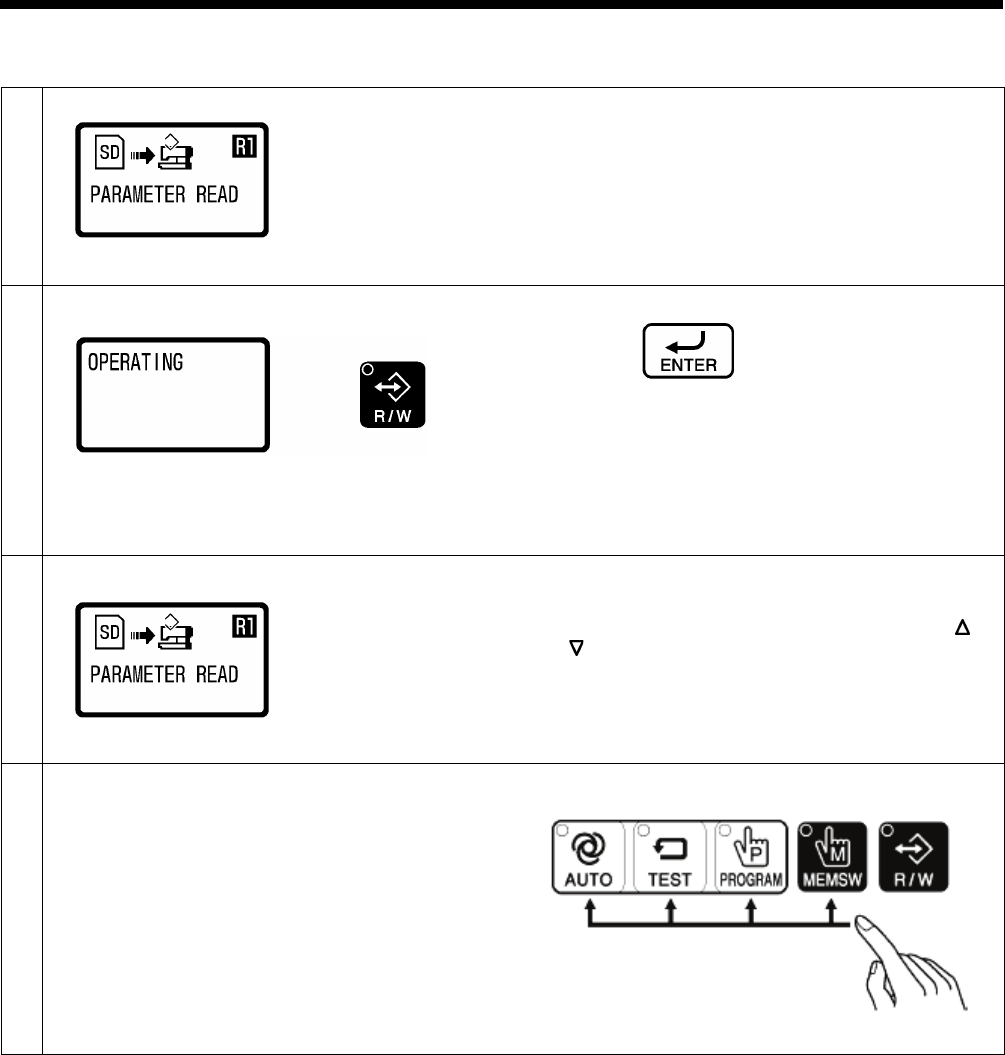
4-4. Reading program data (parameters)
1
Select the [R1] data read/write mode.
Refer to “4-3. Preparation for reading and writing data”.
2
Press the ENTER key.
•
The buzzer will sound and the program data
(parameters) will be read from the SD card and
copied into the sewing machine’s memory.
•
The R/W indicator will flash and “OPERATING” will
be displayed.
•
If no program data exists on the SD card, an error
buzzer will sound.
3
When the display returns to the status in step 1, reading of
the program data is complete.
• If you would like to read more data, press the or
key to select the read/write menu, and then read
the data.
4
Exit data read/write mode.
Press any one of the following four keys to exit data
read/write mode.
2414B
0804D
0805D
0804D
0662D
4. USING SD CARDS
HE-800B
29
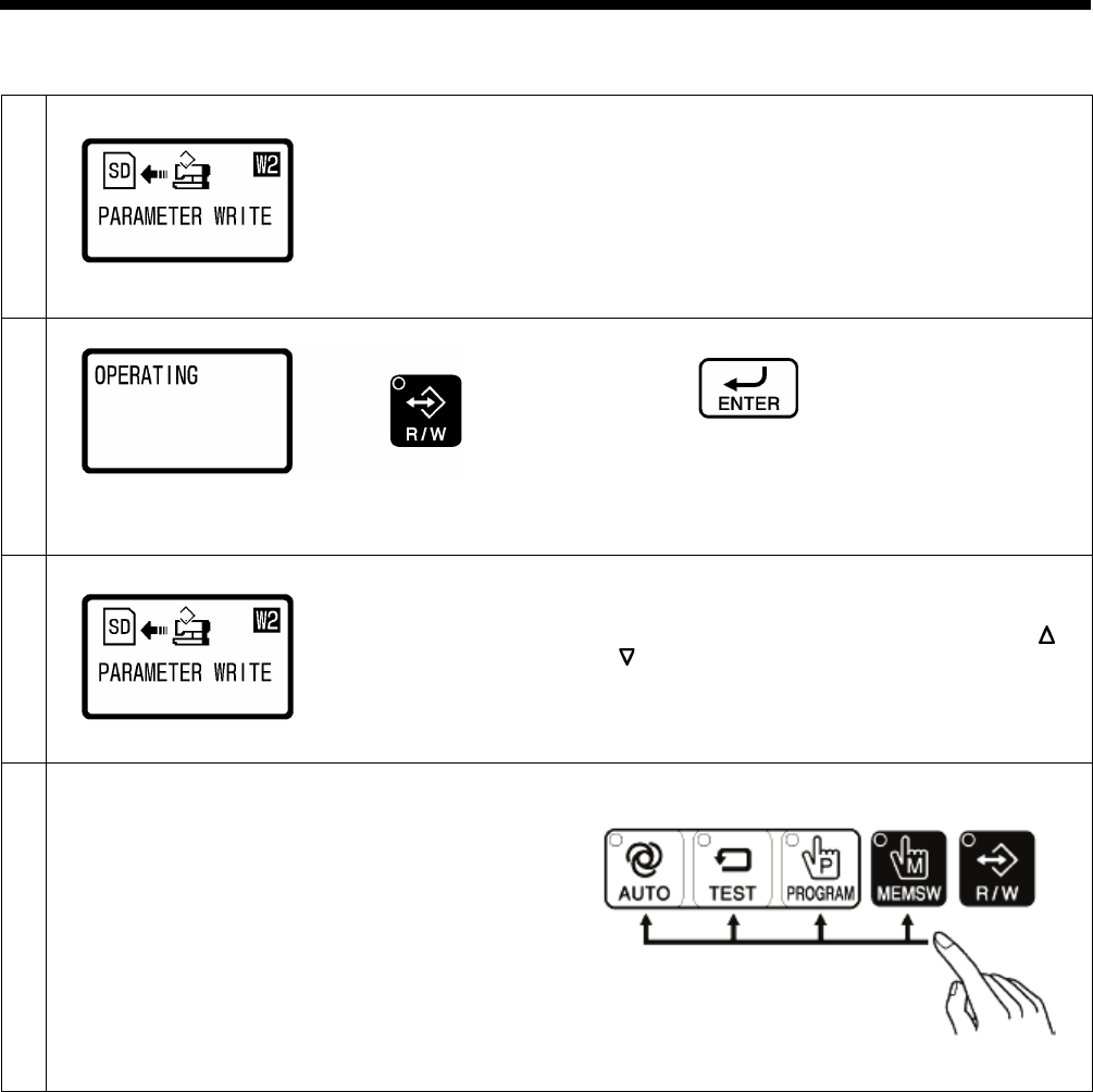
4-5. Writing program data (parameters) to an SD memory card
1
Select the [W2] data read/write mode.
Refer to “4-3. Preparation for reading and writing data”.
2
Press the ENTER key.
•
The buzzer will sound and the program data
(parameters) will be copied to the SD card.
•
The R/W indicator will flash and “OPERATING” will
be displayed.
3
When the display returns to the status in step 1, writing of
the program data is complete.
• If you would like to read more data, press the or
key to select the read/write menu, and then read
the data.
4
Exit data read/write mode.
Press any one of the following four keys to exit data
read/write mode.
2414B
0806D
0805D
0806D
0662D
4. USING SD CARDS
30
HE-800B
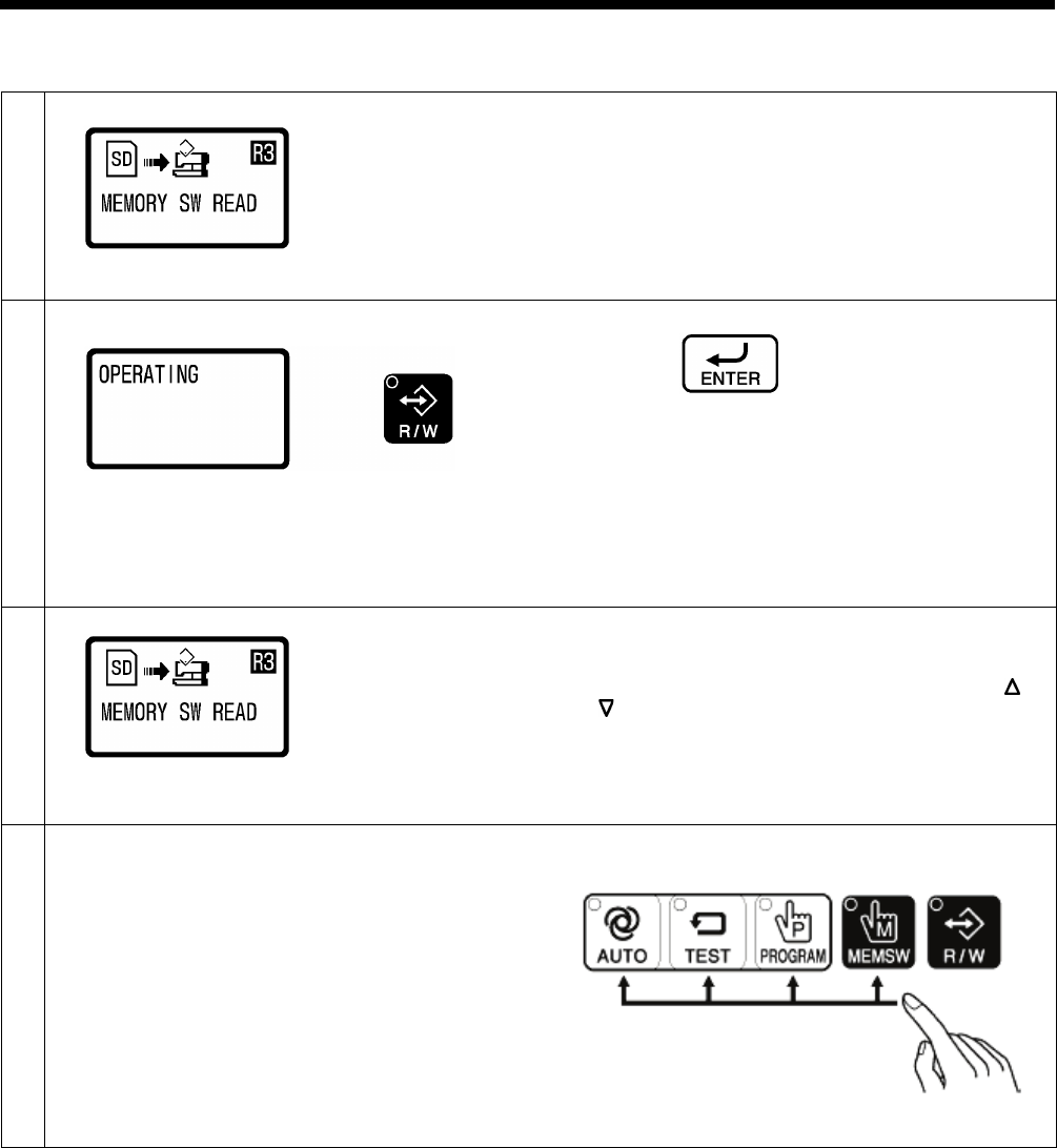
4-6. Reading memory switch data
1
Select the [R3] data read/write mode.
Refer to “4-3. Preparation for reading and writing data”.
2
Press the ENTER key.
• The buzzer will sound and the memory switch data
will be read from the SD card into the sewing
machine’s internal memory.
•
The R/W indicator will flash and “OPERATING” will
be displayed.
•
If no memory switch data exists on the SD card, an
error buzzer will sound.
3
When the display returns to the status in step 1, reading of
the memory switch data is complete.
• If you would like to read more data, press the or
key to select the read/write menu, and then read
the data.
4
Exit data read/write mode.
Press any one of the following four keys to exit data
read/write mode.
2414B
0807D
0805D
0807D
0662D
4. USING SD CARDS
HE-800B
31
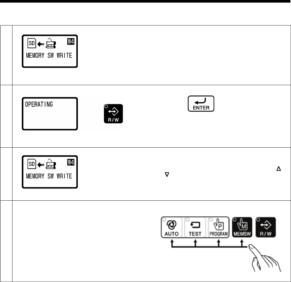
4-7. Writing memory switch data to the SD card
1
Select the [W4] data read/write mode.
Refer to “4-3. Preparation for reading and writing data”.
2
Press the ENTER key.
•
The buzzer will sound and the memory switch data
will be copied to the SD card.
•
The R/W indicator will flash and “OPERATING” will
be displayed.
3
When the display returns to the status in step 1, writing of
the memory switch data is complete.
• If you would like to read more data, press the or
key to select the read/write menu, and then read
the data.
4
Exit data read/write mode.
Press any one of the following four keys to exit data
read/write mode.
2414B
0808D
0808D
0805D
0662D
4. USING SD CARDS
32
HE-800B
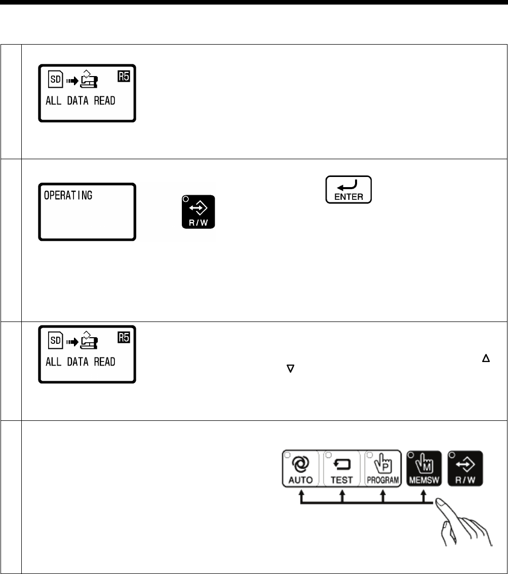
4-8. Reading sewing machine data
1
Select the [R5] data read/write mode.
Refer to “4-3. Preparation for reading and writing data”.
2
Press the ENTER key.
• The buzzer will
sound, and the program data, cycle
program data and memory switch data will be read
from the SD card into the sewing machine’s internal
memory.
•
The R/W indicator will flash and “OPERATING” will
be displayed.
• If no program data or cycle program data or memory
switch data exists on the SD card, an error buzzer
will sound.
3
When the display returns to the status in step 1, writing of
the memory switch data is complete.
• If you would like to read more data, press the or
key to
select the read/write menu, and then read
the data.
4
Exit data read/write mode.
Press any one of the following four keys to exit data
read/write mode.
2414B
0809D
0809D
0805D
0662D
4. USING SD CARDS
HE-800B
33
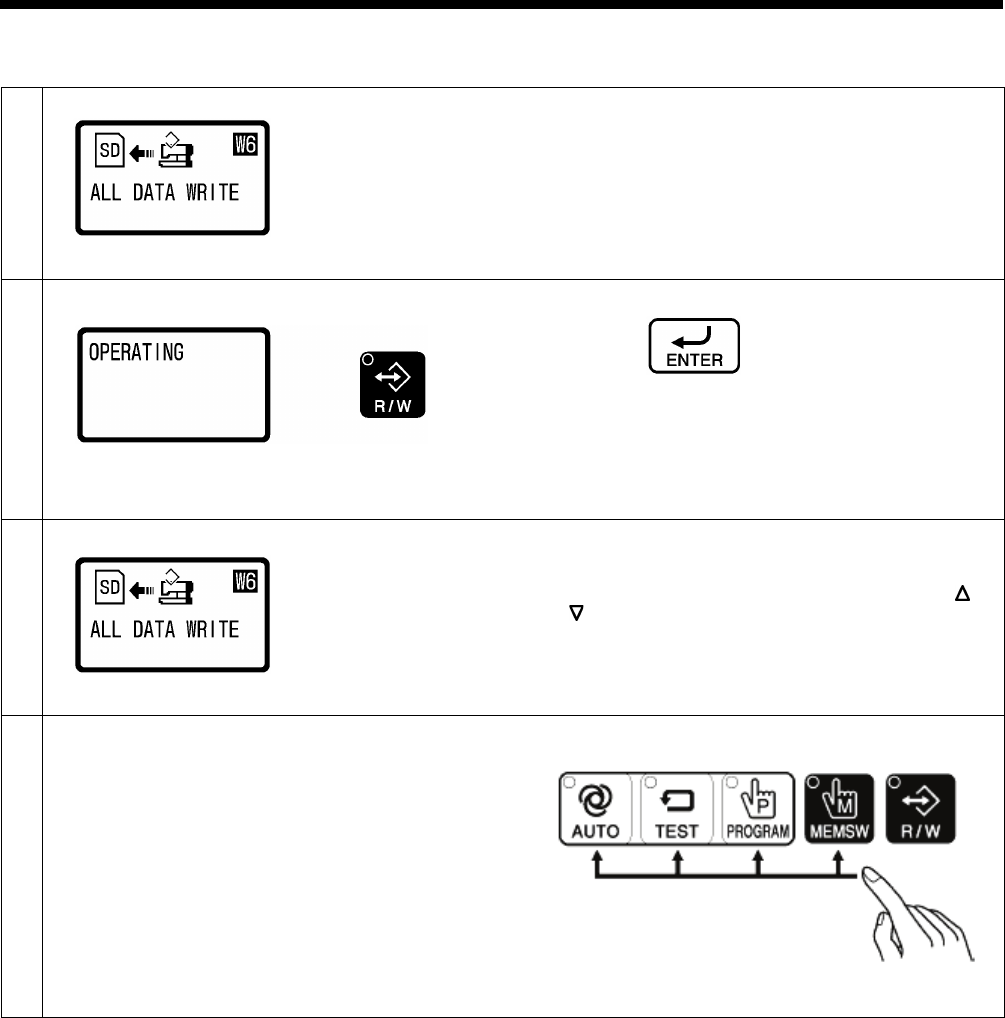
4-9. Writing sewing machine data to an SD card
1
Select the [W6] data read/write mode.
Refer to “4-3. Preparation for reading and writing data”.
2
Press the ENTER key.
•
The buzzer will sound, and the program data, cycle
program data and memory switch data will be copied
to the SD card.
•
The R/W indicator will flash and “OPERATING” will
be displayed.
3
When the display returns to the status in step 1, writing of
the sewing machine data is complete.
• If you would like to read more data, press the or
key to select the read/write menu, and then read
the data.
4
Exit data read/write mode.
Press any one of the following four keys to exit data
read/write mode.
2414B
0810D
0810D
0805D
0662D
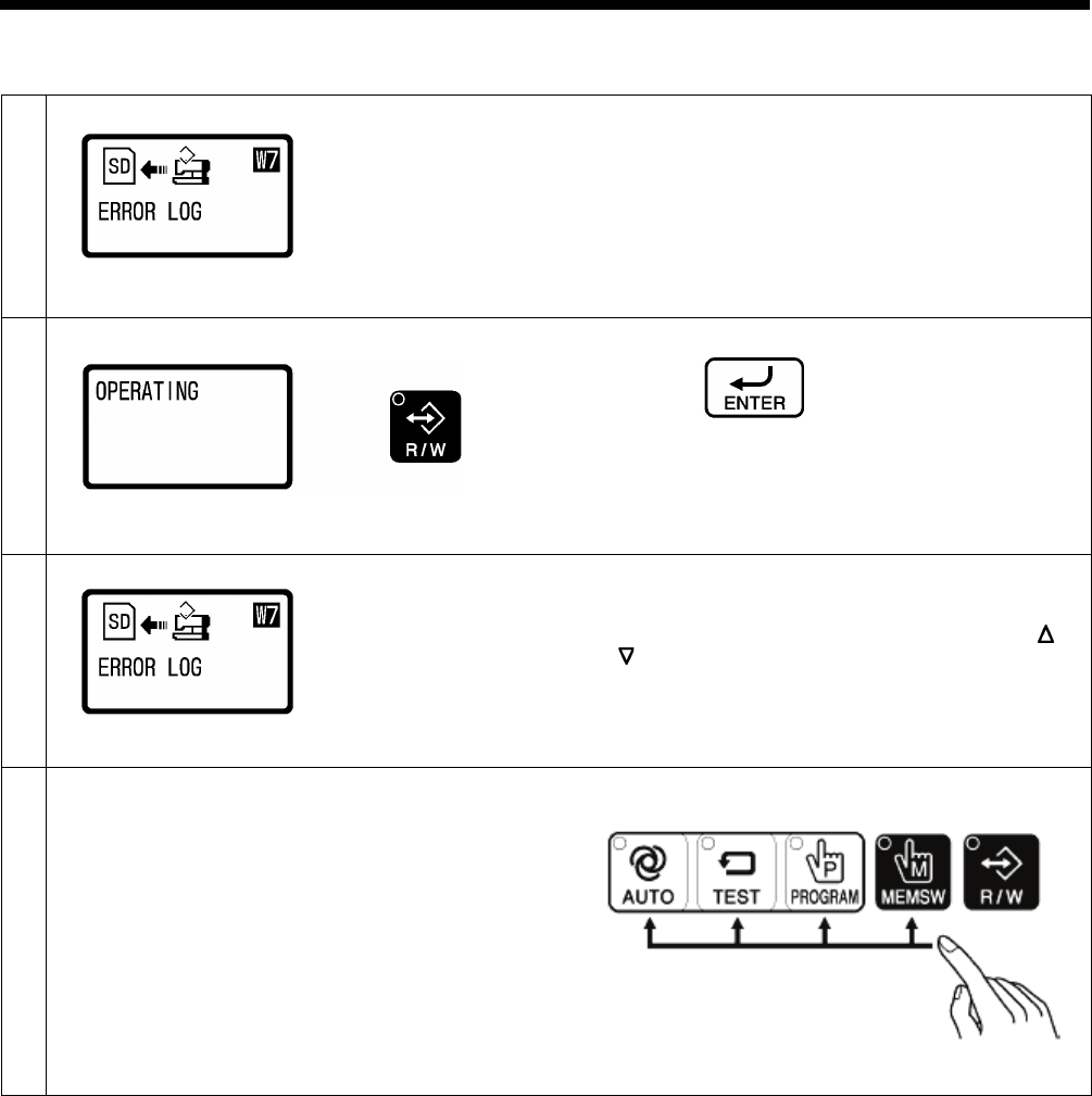
4. USING SD CARDS
34
HE-800B
4-10. Writing error log data to an SD card
1
Select the [W7] data read/write mode.
Refer to “4-3. Preparation for reading and writing data”.
2
Press the ENTER key.
•
The buzzer will sound and the error log data will be
copied to the SD card.
•
The R/W indicator will flash and “OPERATING” will
be displayed.
3
When the display returns to the status in step 1, writing of
the error log data is complete.
• If you would like to read more data, press the or
key to select the read/write menu, and then read
the data.
4
Exit data read/write mode.
Press any one of the following four keys to exit data
read/write mode.
2414B
0811D
0811D
0805D
0662D
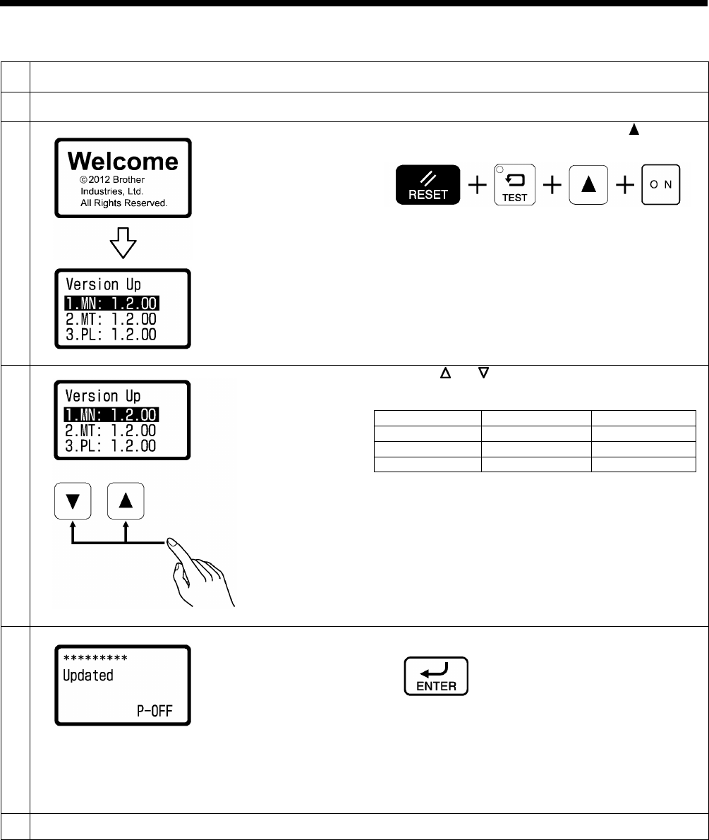
4. USING SD CARDS
HE-800B
35
4-11. Updating the control program version
1
Place the control program that you would like to update into the folder of the SD memory card as specified in “4-2.
Structure of an SD card folder”.
2
With the power turned off, insert the SD card into the SD slot.
Refer to step 1 of “4-3. Preparation for reading and writing data”.
3
While holding down the RESET, TEST and keys, turn
on the power switch.
Keep pressing the key until a beep is heard.
4
Press the or key to select the program to be
updated.
Types
Version No.
Main
[1.Mn]
[*.*.**]
Motor
[2.Mt]
[*.**]
Panel
[3.PL]
[*.**]
• The initial status is for the main program to be
selected.
•
If there is no program to be updated which is stored
on the SD card, “----” will appear in the menu display.
5
Press the ENTER key.
•
The buzzer will sound and updating of the program
version will start.
•
While version updating is in progress, the progress
status will be displayed.
•
When “Updated” is displayed on the screen, version
updating is complete.
6
Turn off the power switch.
0650D
2414B
0637D
0638D
0639D
0640D
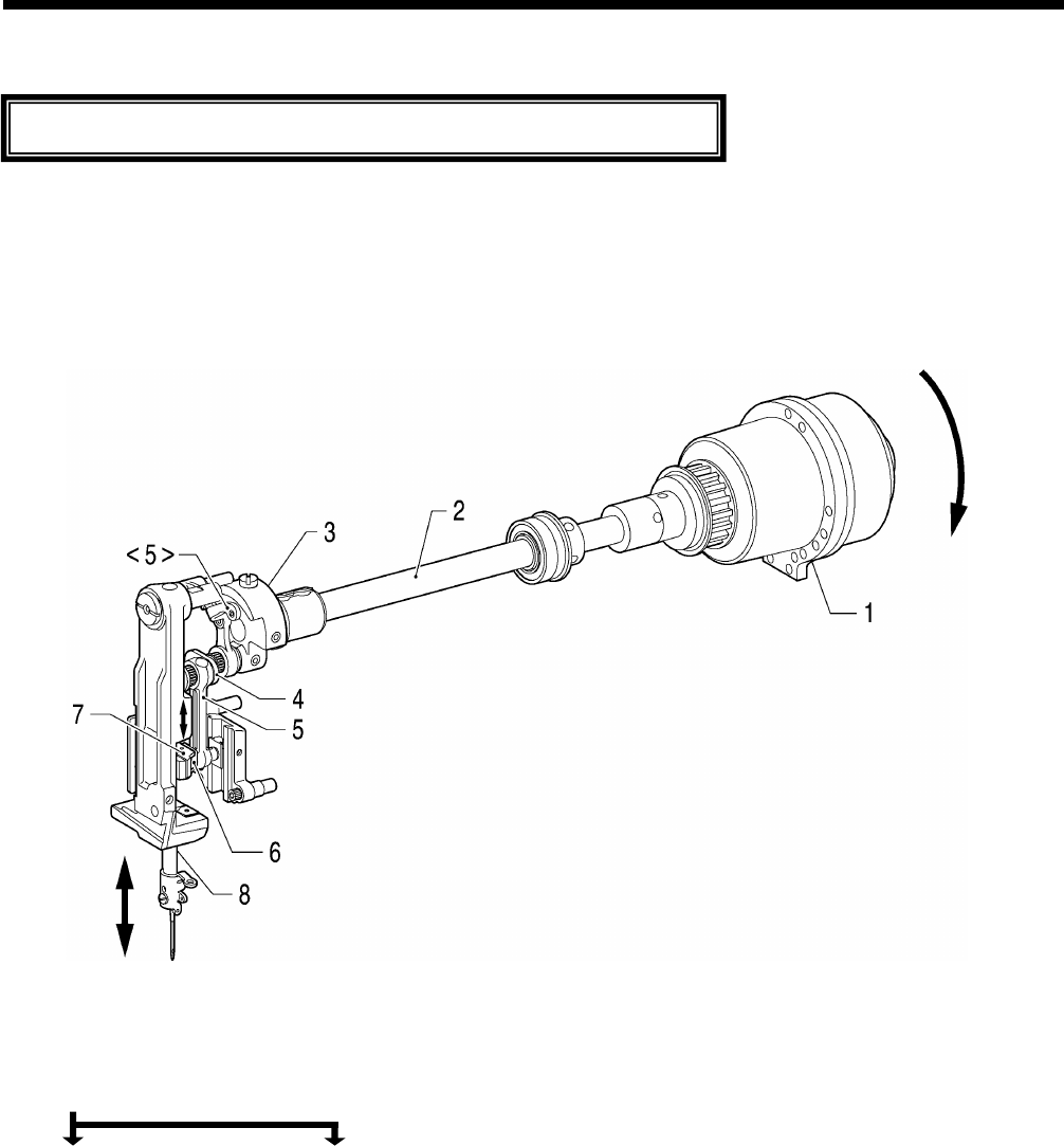
HE-800B
5. MECHANICAL DESCRIPTIONS
36
5. MECHANICAL DESCRIPTIONS
* <number> and [number] indicates the flow of each operations given.
* (number) indicates part names only. (They do not represent the flow of operations.)
5-1. Needle bar and thread take-up mechanisms
1. Motor
2. Upper shaft
3. Needle bar crank
4. Needle bar crank
5. Thread take-up crank <5> Thread take-up assembly
6. Slide block
7. Needle bar clamp
8. Needle bar
The mechanisms operate in the order of the numbers given in the illustrations.
0641D
Rotation direction
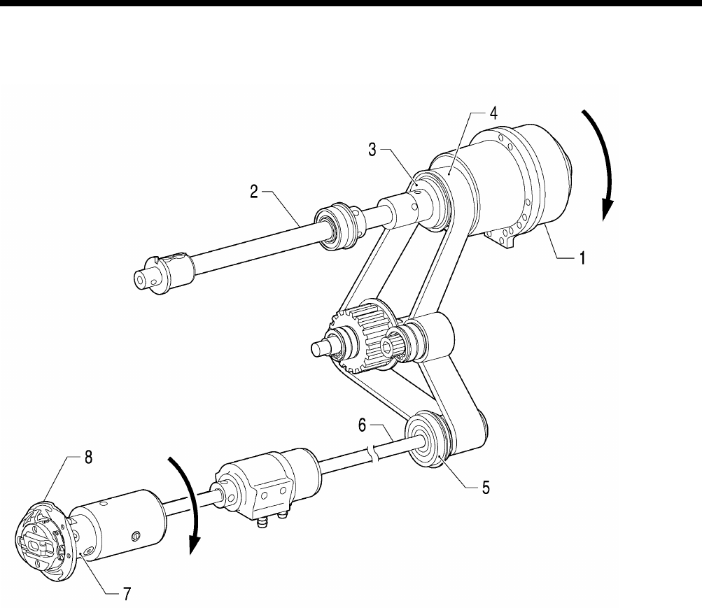
HE-800B
5. MECHANICAL DESCRIPTIONS
37
5-2. Upper shaft, lower shaft and rotary hook mechanisms
1. Motor
2. Upper shaft
3. Joint assy
4. Timing belt
5. Timing pulley
6. Lower shaft
7. Rotary hook joint
8. Rotary hook
0642D
Rotation direction
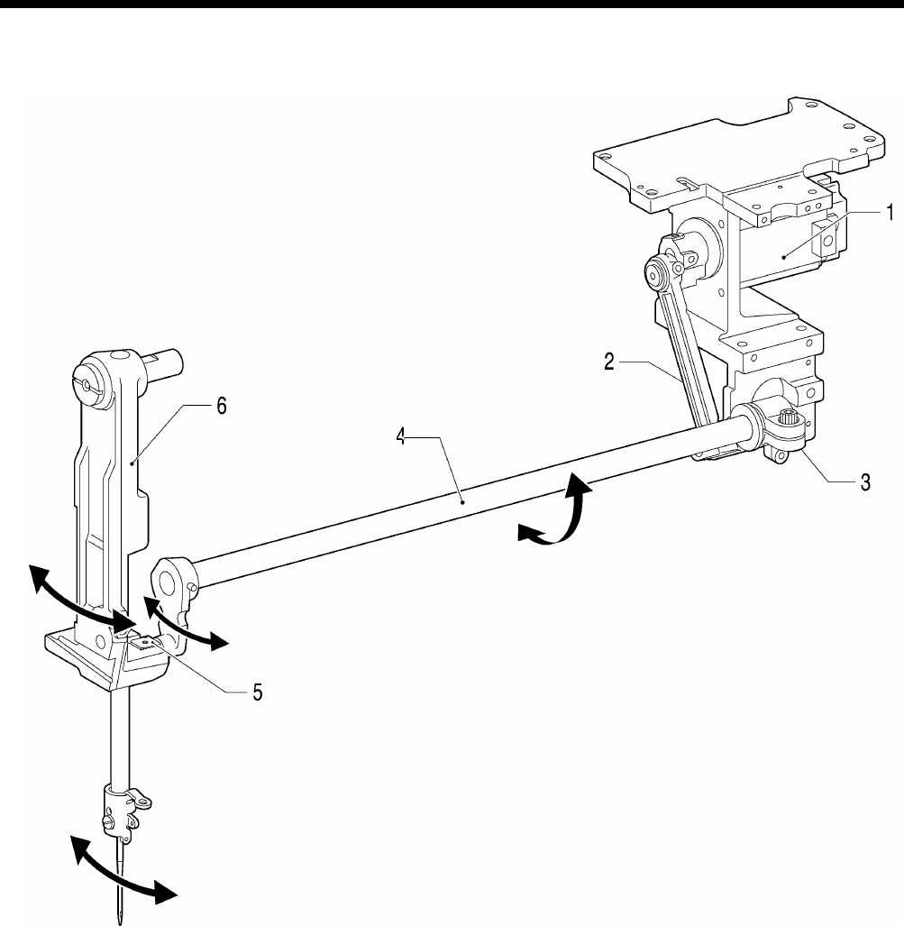
HE-800B
5. MECHANICAL DESCRIPTIONS
38
5-3. Needle zigzag mechanism
1. Pulse motor
2. Zigzag connecting rod
3. Zigzag lever
4. Zigzag lever F assembly
5. Needle bar bracket slide block
6. Needle bar bracket
0643D
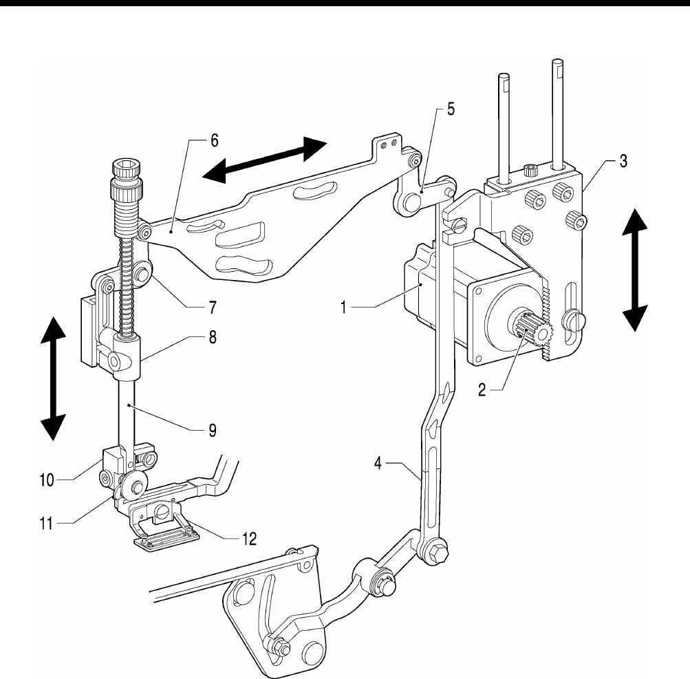
HE-800B
5. MECHANICAL DESCRIPTIONS
39
5-4. Presser foot lifter mechanism
1. Pulse motor
2. Driving gear
3. Presser driving arm
4. Presser foot lifter connecting rod
5. Knee lifter lever
6. Upper thread trimmer driving link
7. Knee lifter lever
8. Presser bar guide bracket assembly
9. Presser bar
10. Presser roller bracket
11. Feed arm support
12. Work clamp
0644D
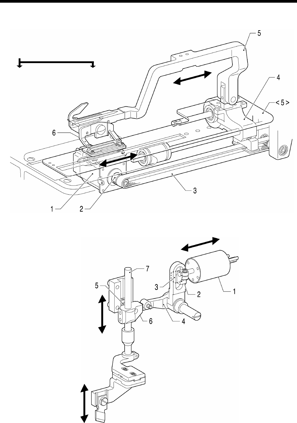
HE-800B
5. MECHANICAL DESCRIPTIONS
40
5-5. Feed mechanism
1. Pulse motor
2. Pulley A
3. Timing belt
4. Feed arm support base
5. Feed arm <5> Length feed plate
6. Work clamp
5-6. Cutter mechanism
1. Cutter solenoid
2. Cutter link bracket
3. Slide block
4. Cutter driving arm
5. Cutter driving link
6. Driving shaft holder assembly
7. Cutter driving shaft
0645D
0646D
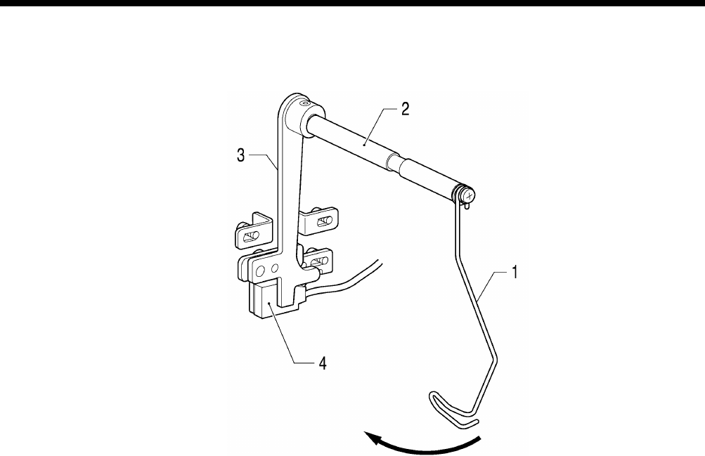
HE-800B
5. MECHANICAL DESCRIPTIONS
41
5-7. Thread breakage detection mechanism
1. Thread guide
2. Thread breakage perceiving shaft
3. Cutter bar fixed plate assembly
4. Sensor
0647D
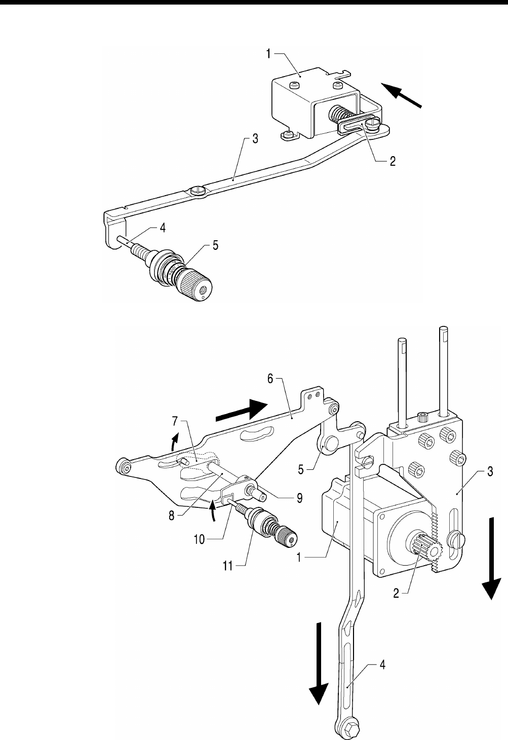
HE-800B
5. MECHANICAL DESCRIPTIONS
42
5-8. Tension release mechanism
[Zigzag tension control]
1. Tension release solenoid assembly
2. Tension release solenoid link
3. Tension release link
4. Tension release pin
5. Tension disc pressers
[Tack tension control]
1. Pulse motor
2. Driving gear
3. Presser driving arm
4. Presser foot lifter connecting rod
5. Knee lifter lever
6. Upper thread trimmer driving link
7. Tension release driving lever
8. Tension release shaft
9. Tension release cam
10. Tension release pin
11. Tension disc pressers
0649D
0648D
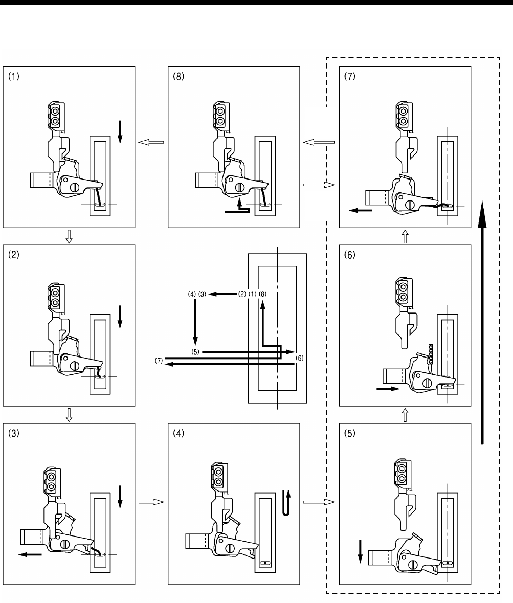
HE-800B
5. MECHANICAL DESCRIPTIONS
43
5-9. Upper thread trimmer mechanism
Upper thread trimmer mechanism operating sequence
Upper thread scissors movement
Sewing starts
(machine starts)
The presser foot drops.
The upper thread scissors
retract and
the presser foot lifts
Presser
foot
drops
Presser
foot
lifts
After 1.5-2.5 mm of feed, the
upper thread scissors
gradually start to open.
After approximately 4.6mm of
feed, the upper thread
scissors are fully open.
Sewing ends.
The upper thread scissors
move forward.
Upper thread trimming
The upper thread is clamped
and cut.
1739B
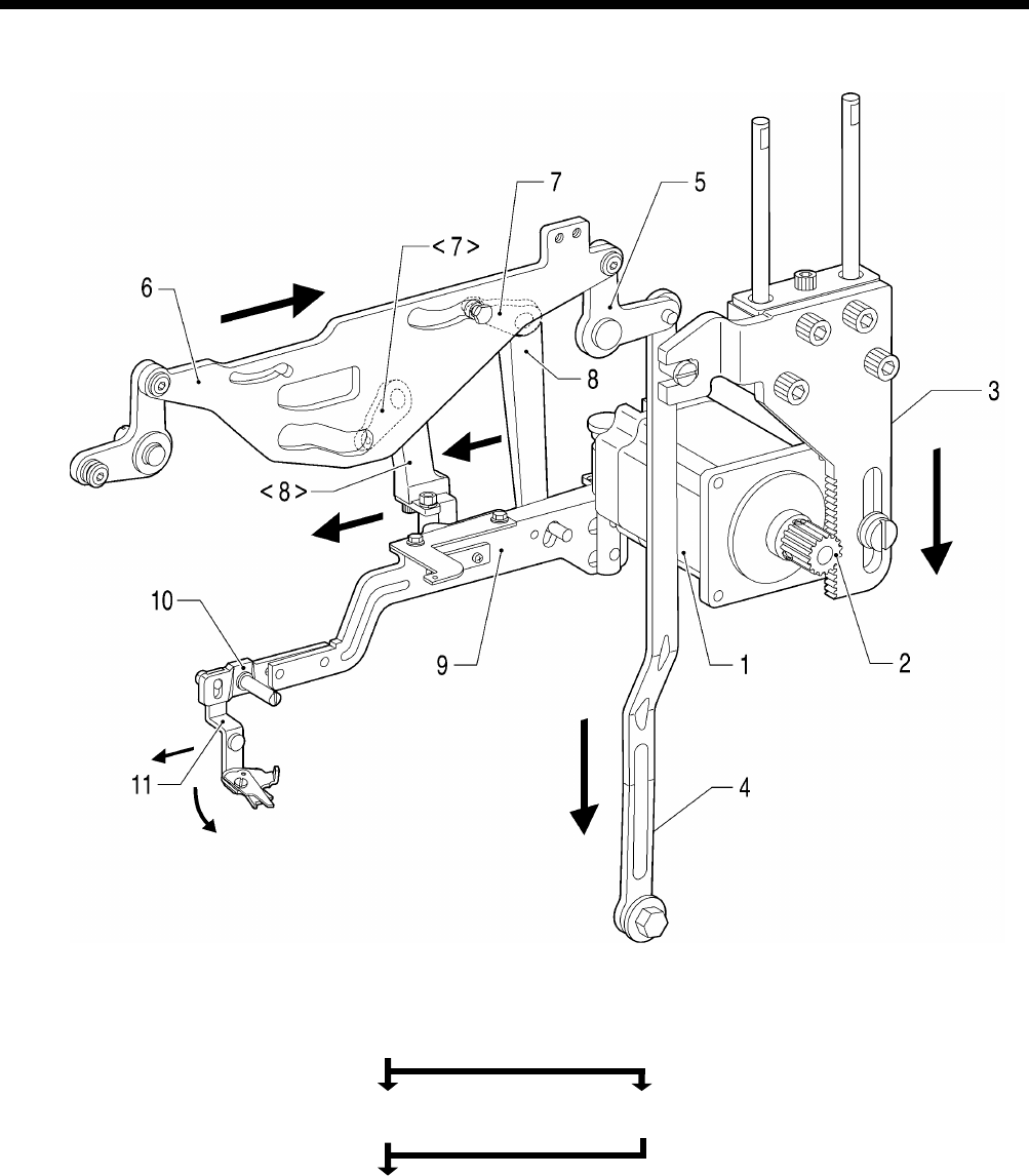
HE-800B
5. MECHANICAL DESCRIPTIONS
44
1. Pulse motor 6. Upper thread trimmer driving link
2. Driving gear
3. Presser driving arm
4. Presser foot lifter connecting rod 7. Trimmer driving lever <7> Driving lever
5. Knee lifter lever 8. Longitudinal feed arm <8> Trimmer driving arm
9. Upper thread trimmer lever
10. Setting plate
11. Upper thread trimmer assembly
0652D
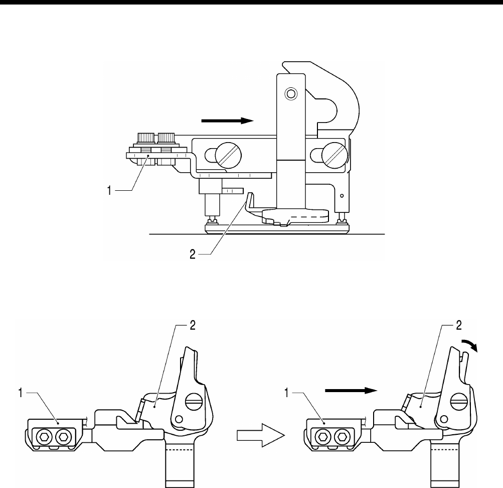
HE-800B
5. MECHANICAL DESCRIPTIONS
45
5-9-1. Upper thread scissors
Gradually opens
1. Opening cam
2. Scissors M
0654D
0653D
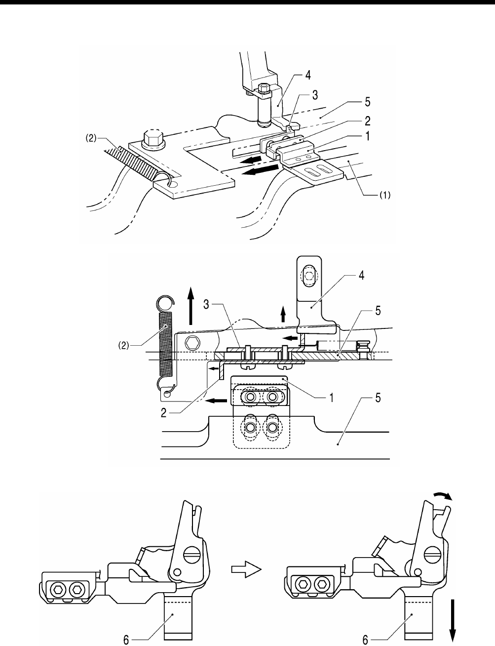
HE-800B
5. MECHANICAL DESCRIPTIONS
46
5-9-2. Upper thread scissors
Open
1. Cam 4. Back stopper (1) Feed arm
2. Back plate 5. Upper thread trimmer lever (2) Extension spring
3. Stop plate 6. Upper thread trimmer assembly
0658D
0657D
0656D
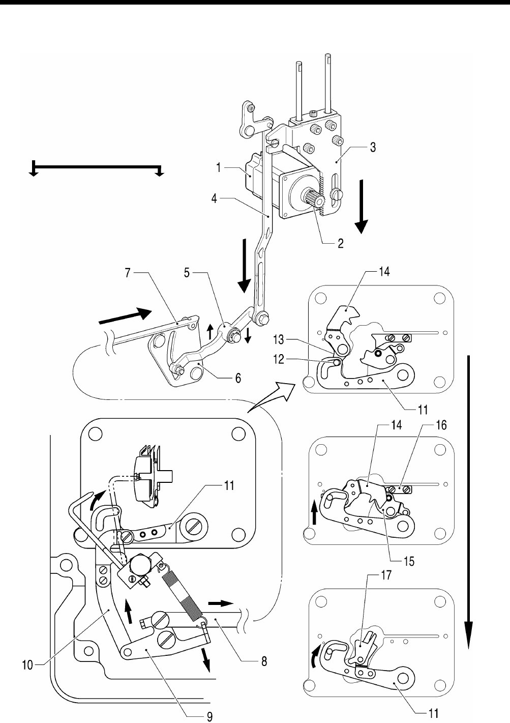
HE-800B
5. MECHANICAL DESCRIPTIONS
47
5-10. Lower thread trimmer mechanism
1. Pulse motor
2. Driving gear
3. Presser driving arm
4. Presser foot lifter connecting rod
5. Lower thread trimmer cam lever
6. Lower thread trimmer cam
7. Lower thread trimmer cam connecting rod
8. Lower thread trimmer cam connecting rod
9. Lower thread trimmer link
10. Lower thread trimmer connecting rod
11. Knife driving lever
12. Collar <12> Fixed knife set
13. Lever
14. Lower thread retainer
15. Lower thread clamp plate
16. Lower thread presser
17. Fixed knife set
0659D
Lower thread retainer, Lower thread trimmer
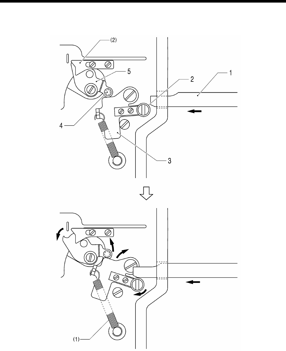
HE-800B
5. MECHANICAL DESCRIPTIONS
48
5-10-1. Lower thread clamp open at the sewing start
Open
1. Feed guide shaft B (1) Spring
2. Roller (2) Lower thread presser
3. Opening plat
4. Collar
5. Lower thread clamp plate
0661D
6. ASSEMBLY
HE-800B
49
6. ASSEMBLY
CAUTION
Disassembly should only be carried out by a qualified
technician.
Turn off the power switch before disassembly,
otherwise the machine may operate if the foot switch
is depressed by mistake, which may result in injury.
Be sure to wear protective goggles and gloves when
handling the lubricating oil and grease, so that they
do not get into your eyes or onto your skin, otherwise
inflammation can result.
Furthermore, do not drink the oil or eat the grease
under any circumstances, as they can cause
vomiting and diarrhea.
Keep the oil out of the reach of children.
When replacing parts and installing optional
accessories, be sure to use only genuine Brother
parts.
Brother will not be held responsible for any accidents
or problems resulting from the use of non-genuine
parts.
If any safety devices have been removed, be
absolutely sure to re-install them to their original
positions and check that they operate correctly
before using the machine.
To prevent accidents and problems, do not modify
the machine yourself.
Brother will not be held responsible for any accidents
or problems resulting from modifications made to
the machine.
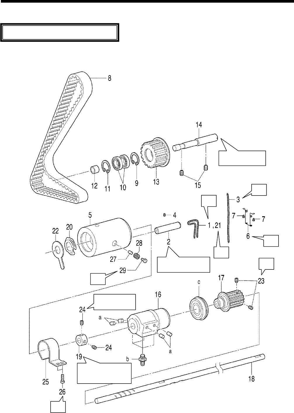
6. ASSEMBLY
HE-800B
50
6-1. Lower shaft and idle pulley mechanisms
* Refer to the detailed descriptions on the next page for details on A to G in the illustration.
0663D
Gently push while
installing.
A
C
D
E
F
G
Insert as far as the
bottom of the hole.
Set so that the worn
surface is facing toward
the bush.
Install so that
there is no play.
B
Assemble each part in order of the numbers.
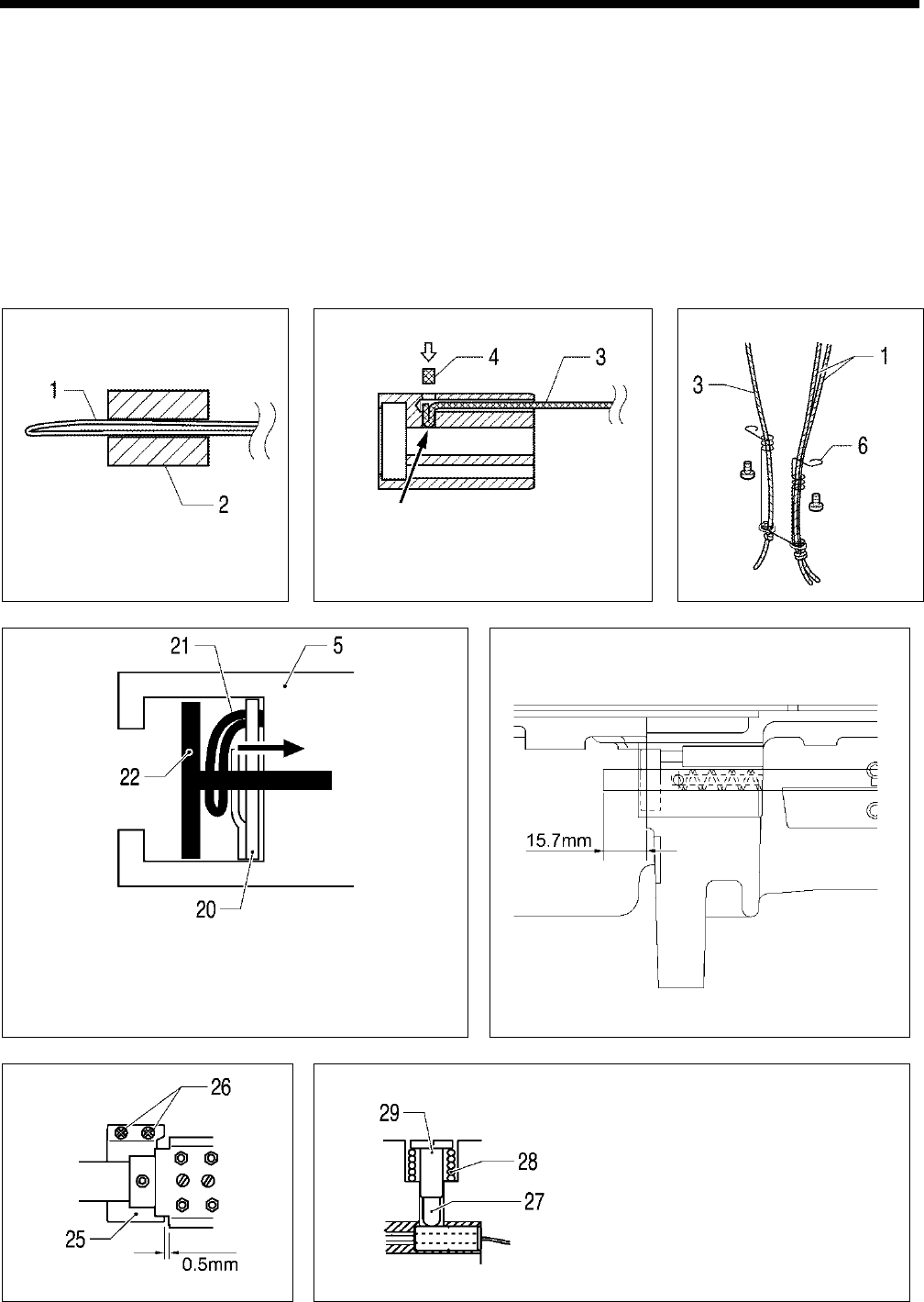
6. ASSEMBLY
HE-800B
51
1. Wick
2. Collar
3. Wick
4. Felt
5. Rotary hook shaft bush
6. Rotary hook felt support
7. Screws [2 pcs]
8. Timing belt
9. Retaining ring
10. Ball bearing [2 pcs]
11. Retaining ring
12. Idle pulley
13. Collar
14. Shaft
15. Set screws [2 pcs]
16. Bush assy M
17. Timing pulley
18. Lower shaft
19. Set screw collar
20. Wick
21. Spring
22. Rotary hook felt
23. Set screws [2 pcs]
24. Set screws [2 pcs]
25. Cover
26. Screws [2 pcs]
27. Rubber presser
28. Spring
29. Screw
a. Rubber plugs [4 pcs]
b. Oil feeding pipe [4 pcs]
c. Bearing
A
B
C
D
Check that the spring (20) is not compressed when the wick
(21
) is pulled in the direction of the arrow. Push the end of the
felt (22) into the hole in the bush (5) and stop it from turning.
E
F
G
As a guide for the lubrication amount, the
optimum position can be obtained if the
screw (29) is tightened as much as possible
and then loosened about two turns. Refer to
“7-19. Adjusting the rotary hook lubrication”
to check and adjust the lubrication amount.
0665D
0668D
0667D
0669D
0664D 0660D 0666D
Push in the felt (4) so that the
wick (3)
is touching the lower
shaft (18).
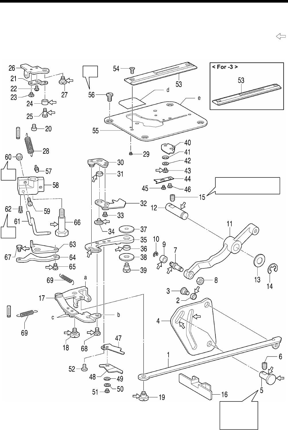
6. ASSEMBLY
HE-800B
52
6-2. Lower thread trimmer mechanism
* Refer to the detailed descriptions on the next page for details on A to C in the illustration.
* Apply the grease specified by Brother (Power Knock WB2 from JX Nippon Oil & Energy) in the places indicated by .
A
B
C
0857D
Tighten so
that (4) moves
smoothly with
no play.
Tighten so that (11) moves
smoothly with no play.
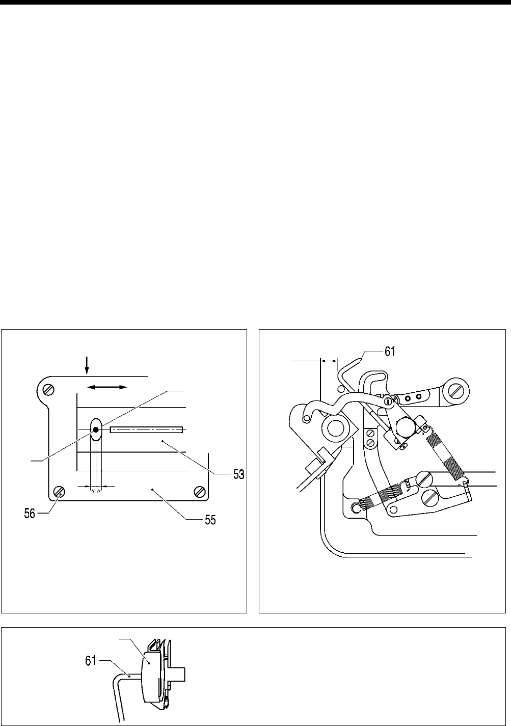
6. ASSEMBLY
HE-800B
53
1. Lower thread trimming cam
connecting rod
2. Driving lever roller
3. Shoulder screw
4. Lower thread trimmer cam
5. Lever shaft
6. Set screw
7. Roller shaft
8. Nut
9. Roller
10. Retaining ring
11.
Lower thread trimmer cam
lever
12. Cam shaft, ;L-TR
13. Washer
14. Retaining ring
15. Set screw
16. Cover
17. Lower thread trimmer link
18. Shoulder screw
19. Shoulder screw
20. Screw
21. Opening plate, B
22. Screw
23. Shoulder screw
24. Roller
25. Roller shaft
26. Opening plate, A
27. Shoulder screw
28. Spring
29. Screw
30. Lever assembly
31. Collar
32. Lower thread retainer
33. Screws [2 pcs]
34. Screw
35. Knife driving lever
36. Collar
37. Plain washer D
38. Plain washer U
39. Shoulder screw
40.
Lower thread clamp plate
assembly
41. Washer
42. Plain washer
43. Shoulder screw, SM3.18
44. Lower thread presser
45. Shoulder screw
46. Screw
47. Lower fixed knife assy
48. Movable knife assy
49. Washer
50. Plain washer
51. Bind
52. Bind
53. Needle plate
54. Flat screws [2 pcs]
55. Base plate
56. Screws [4 pcs]
57. Spring hook U
58. Bobbin presser bracket
59. Screw
60. Nut
61. Bobbin presser
62. Screw
63. Auxiliary plate
64. Opening plate
65. Shoulder screw
66. Shoulder screw
67. Shoulder screw
68. Shoulder screw
69. Spring [2 pcs]
a. Lower thread trimmer link assy
A
b. Lower thread connecting rod A
c. Screws [2 pcs]
d. Needle plate cover
e. Base plate
A
Move the base plate (55) so that the needle is exactly in
the middle of the needle hole in the needle plate (53) in
the forward and back directions, and then tighten the four
screws (56).
B
Turn on the power, and after the sewing machine returns
to the home position, turn the screw (59) and the nut (60)
to adjust so that the clearance between the bobbin presser
(61) and the edge of the bed is approximately 12.5 mm.
C
Install so that the end of the bobbin presser (61) is at the
center of the bobbin case.
0671D
Bobbin case
0670D
Needle
Needle hole
0672D
Approx.12.5 mm
Press down
Forward Back
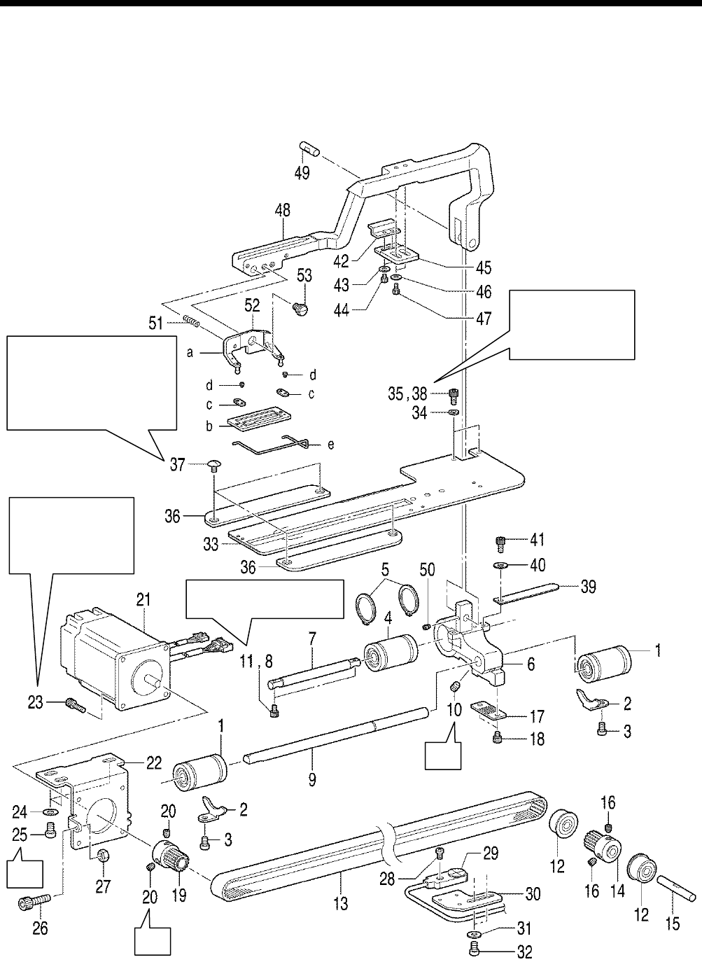
6. ASSEMBLY
HE-800B
54
6-3. Feed mechanism
* Refer to the detailed descriptions on the next page for details on A to C in the illustration.
A
B
C
0708D
Tighten the four screws (37)
so that the window in the
length feed plate (33) is in the
center of the needle plate
when the feed arm (48)
is moved forward and back.
Tighten the two bolts
(38) so that the feed
arm (48
) moves
smoothly.
Be careful to install
so that the motor
harness opening is
facing the correct
way. Refer to C
Tighten so that (6) moves
back and forth smoothly.
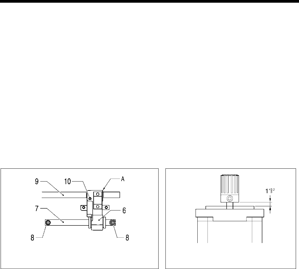
6. ASSEMBLY
HE-800B
55
1. Linear bushing [2 pcs]
2. Ball bearing stoppers [2 pcs]
3. Screws [2 pcs]
4. Linear bushing
5. Retaining rings [2 pcs]
6. Feed arm support base
7. Feed guide shaft A
8. Socket bolts [2 pcs]
(Temporarily tighten)
9. Feed guide shaft B
10. Set screw
11. Socket bolts [2 pcs] (Fully
tighten)
12. Ball bearing [2 pcs]
13. Timing belt
14. Pulley
15. Support shaft
16. Set screws [2 pcs]
17. Belt holder
18. Bolt [2 pcs]
19. Pulley
20. Set screws [2 pcs]
21. Feed motor
22. Motor mounting bracket
23. Socket bolts [4 pcs]
24. Plain washers [3 pcs]
25. Screws [3 pcs]
26. Socket bolt
27. Nut
28. Feed sensor
29. Screw
30. Feed sensor support plate
31. Washers [2 pcs]
32. Screws [2 pcs]
33. Length feed plate
34. Spring washers [2 pcs]
35. Socket bolts [2 pcs]
(Temporarily tighten)
36. Feed presser plate [2 pcs]
37. Screws [4 pcs]
38. Socket bolts [2 pcs] (Fully
tighten)
39. Feed cover
40. Plain washer
41. Socket bolt
42. Cam
43. Washers [2 pcs]
44. Socket bolts [2 pcs]
45. Support plate
46. Washers [2 pcs]
47. Socket bolts [2 pcs]
48. Feed arm
49. Feed arm support shaft
50. Set screw
51. Spring
52. Work clamp assembly
53. Shoulder screw
54. Feed arm support
a. Work clamp support M
b. Work clamp 25RS
c. Spring plate [2 pcs]
d. Screws [2 pcs]
e. Finger guard M
A
Align reference line A on feed guide shaft B with the edge of the
feed arm support base, and then tighten the set screw (10).
B
Assemble as shown in the illustration.
0673D 0772D
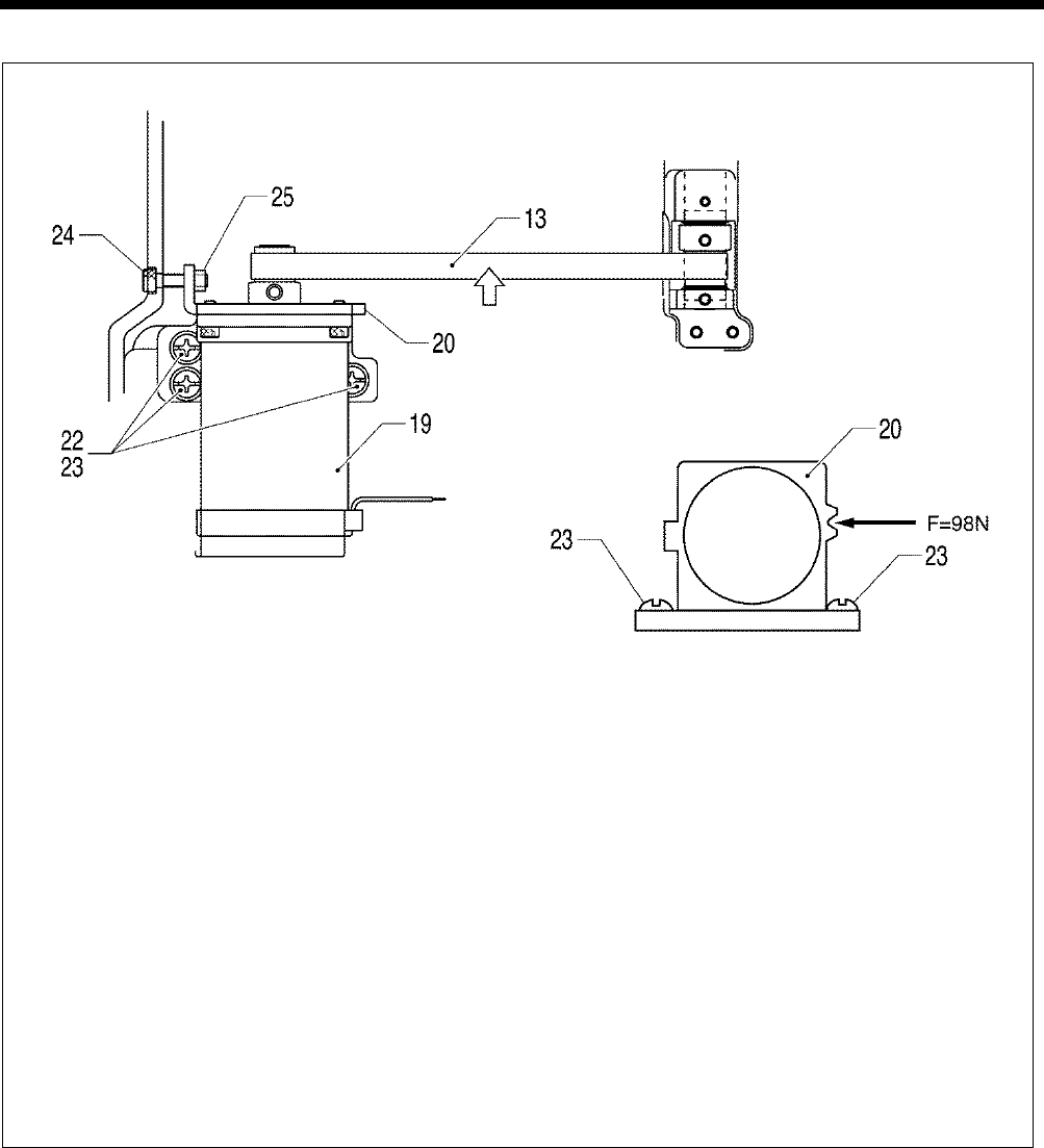
6. ASSEMBLY
HE-800B
56
C
Repeat steps1 to 3 to adjust the belt tension until it is within the ranges given below.
・ When using a new belt: 40 - 45 N
・ When reusing an old belt: 30 - 45 N
1) Loosen the three screws (23) so that the feed pulse motor (19) moves easily.
2) Use the adjustment screw (24) to adjust the belt tension.
3) Tighten the three screws (23).
4) Check that the timing belt (13) moves smoothly.
5) Loosely tighten the nut (25).
* Be sure
to use a belt tension gauge to measure the belt tension, and measure at the position shown in the
illustration.
* The belt tension gauge should be set to measure a unit weight of 0.25 gf/cm, a belt width of 10 mm and a span
length of 169 mm.
[Reference]
If no belt tension gauge is available, use a push pull gauge to apply 98N of force to the notch in the motor mounting bracket
(20) while tightening the three screws (23).
0675D
Measurement position
(Middle of belt)
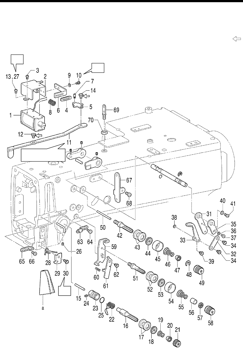
6. ASSEMBLY
HE-800B
57
6-4. Threading mechanism
* Before carrying out the assembly in “6-4. Threading mechanism””, carry out the assembly in steps 1 to 13 in “6-9.
Lubrication mechanism”.
* Refer to the detailed descriptions on the next page for details on A to C in the illustration.
* Apply the grease specified by Brother (Power Knock WB2 from JX Nippon Oil & Energy) in the places indicated by .
A
B
C
0709D
Insert from the face
plate side.
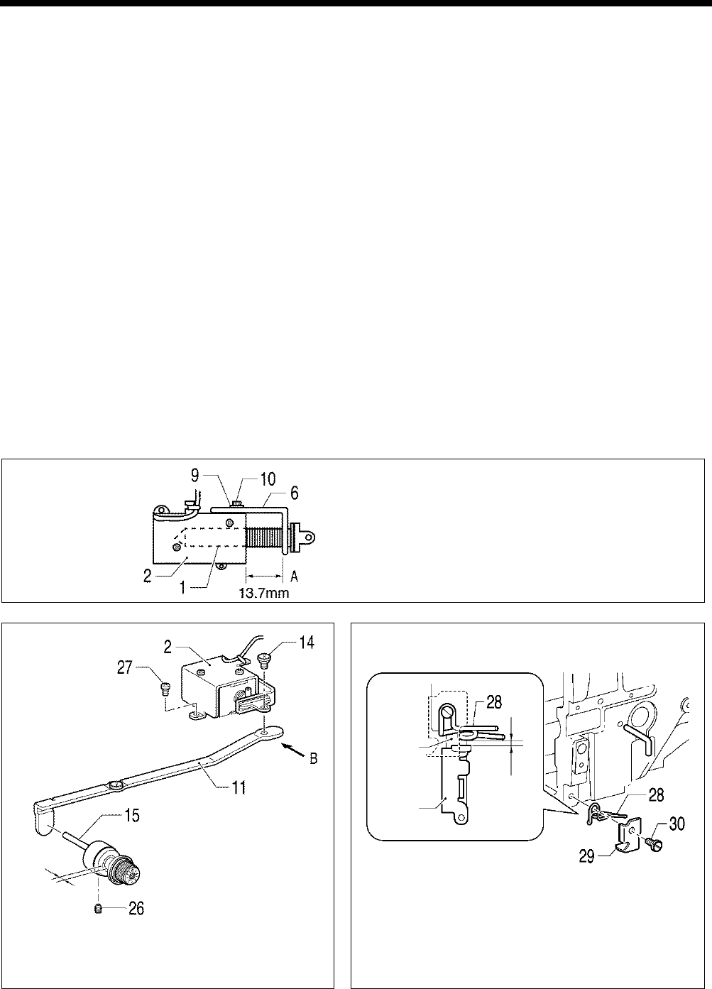
6. ASSEMBLY
HE-800B
58
1. Tension release solenoid
2. Solenoid holder
3. Screws [3 pcs]
4.
Tension release rubber
assembly
5. Tension release solenoid link
6. Plate
7. Plunger pin
8. Spring
9. Plain washer
10. Socket bolt
11. Tension release link
12. Shoulder screw
13.
Screws [2 pcs] (Temporarily
tighten)
14. Shoulder screw
15. Tension release pin
16. Tension stud L
17. Tension disc [2 pcs]
18. Tension disc pressers
19. Tension spring
20. Washer on tension spring
21. Tension nut
22. Thread take-up spring
23. Tension stud bracket
24. Set screw
25. O Ring
26. Set screw, socket
27. Screws [2 pcs] (Fully tighten)
28. Thread guide, L ;arm
29. Thread guide cover
30. Screw
31. Adjusting lever
32. Lever link
33. Tension take-up lever
34. Shoulder screws [2 pcs]
35. Lever
36. Washer
37. Screw
38. Washer
39. Shoulder screw
40. Plain washer
41. Screw
42. Sub tension stud
43. Tension disc [2 pcs]
44. Tension disc pressers
45. Tension nut collar
46. Tension spring
47. Washer
48. Knob nut stopper
49. Tension nut
50. Tension release pin
51. Tension stud
52. Tension disc [2 pcs]
53. Tension disc pressers
54. Tension disc pressers
55. Tension spring
56. Tension nut collar
57. Guide block
58. Tension nut
59. Tension release lever bracket
60. Spring
61. Tension release lever
62. Shoulder screw
63. Arm thread guide
64. Screw
65. Arm thread guide
66. Screw
67. Thread retainer
68. Screws [2 pcs]
69. Threading bar, U
70. Nut
a. Threading plate
A
Tighten the socket bolt (10) so that the distance A
between the end of the solenoid 1 and the plate
(6) is 13.7 mm.
B
Tighten the two screws (27) so that the tension disc
opening amount is 0.5 to 1.0 mm when the tension
release link (11) is moved in the direction of B.
C
(After installing the needle bar thread guide by referring to
"6-10. Needle bar and thread take-up mechanisms"), tighten
the screw (30) to adjust the gap between the needle bar
thread guide and arm thread guide L (28) to 0.5 mm or more
when the needle bar is at its highest point at the maximum
right zigzag position (3 mm).
0677D
0676D
0678D
Needle
bar
thread
guide
Needle
bar
0.5 mm
or more
0.5 to 1.0 mm
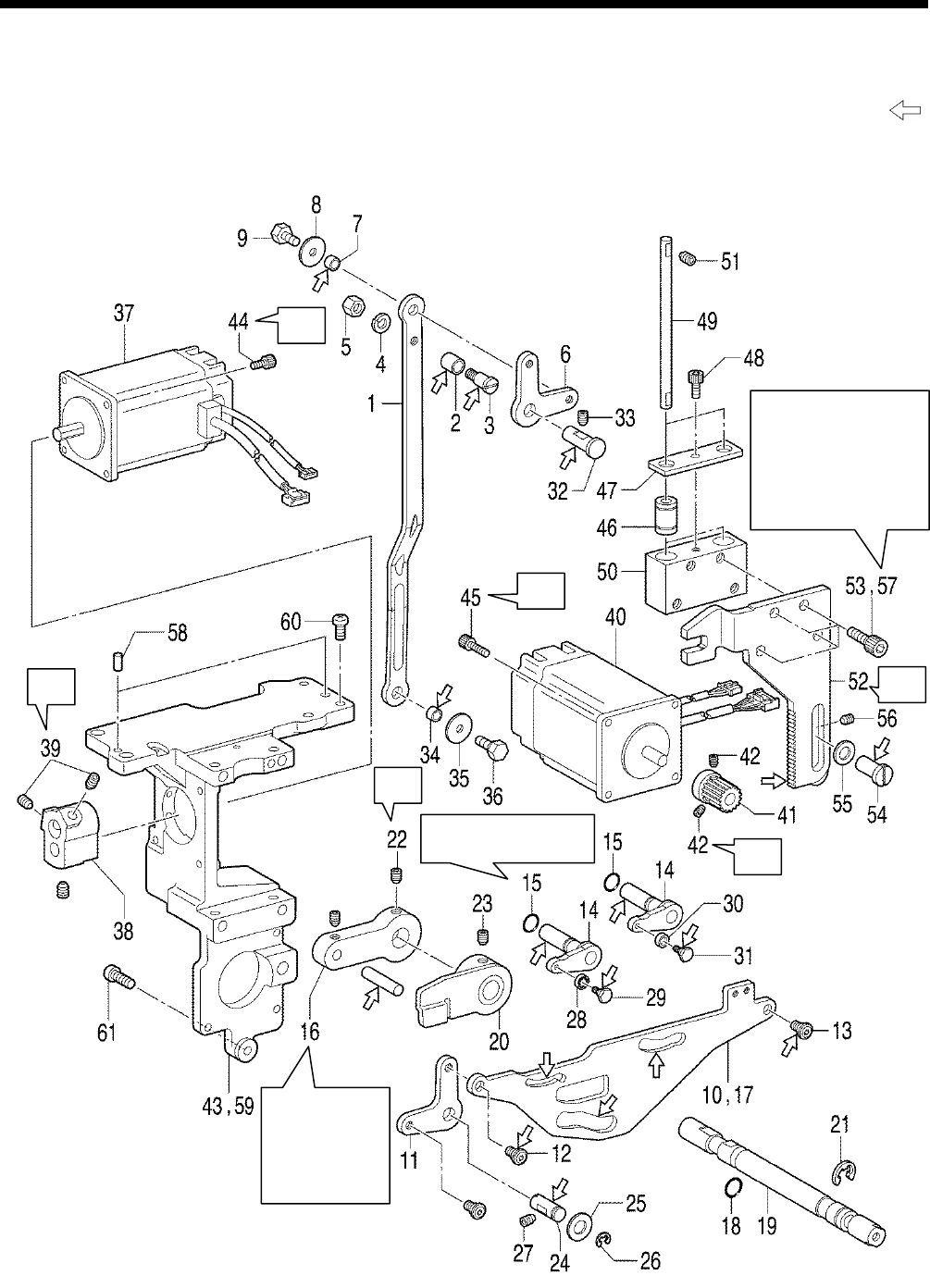
6. ASSEMBLY
HE-800B
59
6-5. Presser lifter mechanism
* Refer to the detailed descriptions on the next page for details on A to D in the illustration.
* Apply the grease specified by Brother (Power Knock WB2 from JX Nippon Oil & Energy) in the places indicated by .
A
B
C
B
C
D
0710D
Insert the pin
into the groove
in the cam
(20), and then
insert it into the
arm.
Tighten the four socket
bolts (57) so that the
presser driving arm
(52)
moves up and
down easily and so
that there is very little
play in the gear.
Insert into the countersunk
hole in the arm.
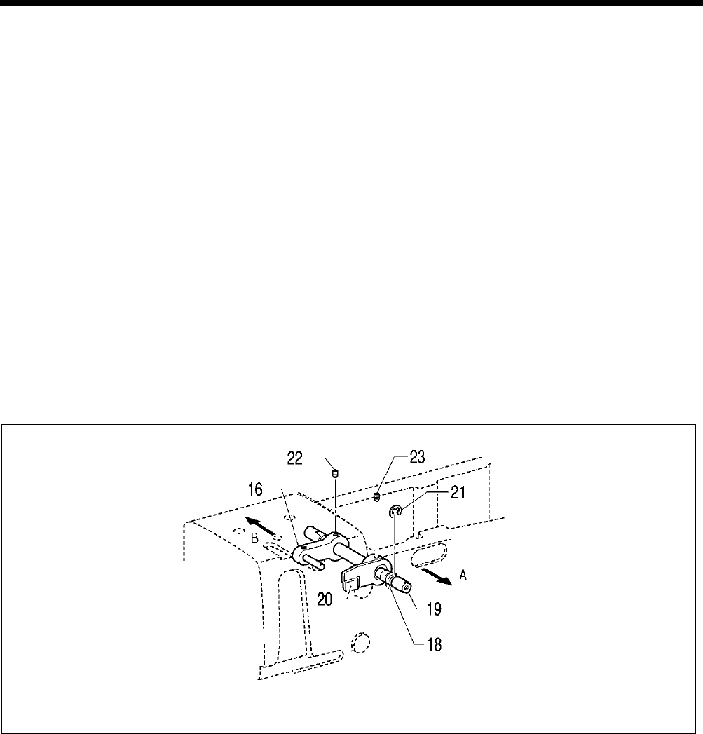
6. ASSEMBLY
HE-800B
60
1. Presser foot lifter connecting
rod
2. Roller
3. Shoulder screw
4. Spring washer
5. Nut
6. Knee lifter lever
7. Spacer
8. Washer
9. Bolt
10.
Upper thread trimmer driving
link
11. Knee lifter lever
12. Shoulder screw
13. Shoulder screw
14. Trimmer driving lever [2 pcs]
15. O rings [2 pcs]
16. T-release driving lever assy
17.
Upper thread trimmer driving
link
18. O Ring
19. Tension release shaft
20. Tension release cam
21. Retaining ring
22. Set screw
23. Set screw (Temporarily
tighten)
24. Lifter shaft
25. Plain washer
26. Retaining ring
27. Set screw
28. Bearing
29. Shoulder screw
30. Driving lever roller
31. Shoulder screw
32. Lifter shaft A
33. Set screw
34. Spacer
35. Washer
36. Bolt
37. Zigzag pulse motor
38. Motor lever
39. Set screws [2 pcs]
40. Presser lifter pulse motor
41. Gear
42. Set screws [2 pcs]
43. Motor bracket
44. Socket bolts [4 pcs]
45. Socket bolts [4 pcs]
46. Linear bush [2 pcs]
47. Bearing holder
48. Socket bolt
49. Guide shaft [2 pcs]
50. Guide bracket
51. Set screws [4 pcs]
52. Presser driving arm
53. Socket bolts [4 pcs]
(Temporarily tighten)
54. Driving arm presser
55. Washer
56. Set screw
57. Socket bolts [4 pcs] (Fully
tighten)
58. Positioning pin [2 pcs]
59. Motor bracket assembly
60. Screws [4 pcs]
61. Screw
A
While pushing the tension release shaft (19) in the direction of the arrow A, and also pushing the tension release driving
lever (16) in the direction of the arrow B, tighten the set screw (22) on the screw flat of the tension release shaft (19).
0679D
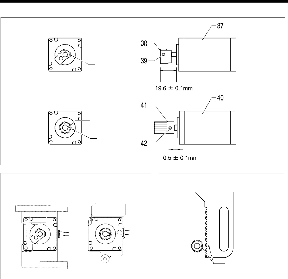
6. ASSEMBLY
HE-800B
61
B
C
Direction of the harness
D
0681D 0691D
0680D
Screw stop side
Index mark
Zigzag motor
Presser lifter motor
Index marks aligned
Presser lifter motor
Zigzag motor
Screw stop side
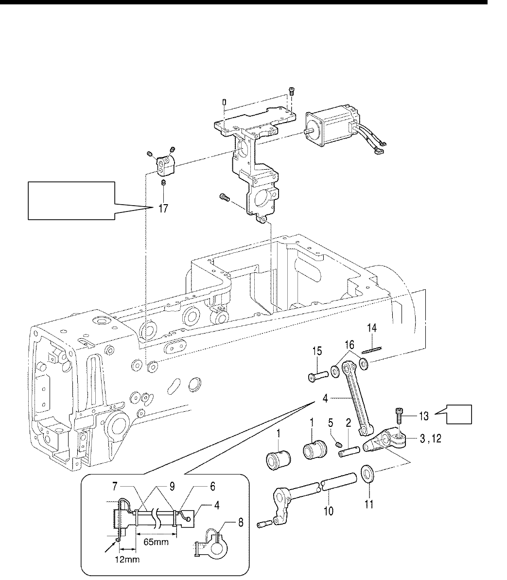
6. ASSEMBLY
HE-800B
62
6-6. Needle zigzag mechanism
* Refer to the detailed descriptions on the next page for details on A in the illustration.
1. Bush, z-lever
2. Zigzag connecting rod shaft
3. Zigzag lever
4. Zigzag connecting rod
5. Set screw
6. Wick
7. Oil tube
8. Felt
9. Fastening bands [2 pcs]
10. Zigzag lever shaft
11. Thrust collar
12. Zigzag lever
13. Socket bolt
14. Wick
15. Motor lever shaft
16. Washer
17. Set screw
A
0711D
Knot
Tighten so that there
is no play in the
thrust direction.
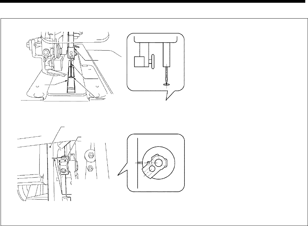
6. ASSEMBLY
HE-800B
63
A
1)
Install the needle to the needle bar, and
secure it in position so that the tip of the
needle is aligned with the center of the
cutter groove in the needle plate.
2) Tighten the socket bolt (13) at the position
where the index hole in the motor lever and
the reference line on the motor bracket are
aligned.
*
At this time, tighten so that there is no
play in the thrust direction.
0683D
0684D
Align the center of
the cutter groove
and the tip of the
needle.
Motor bracket
Motor lever
Align the reference
line on the motor
bracket and the
index hole in
the motor lever.
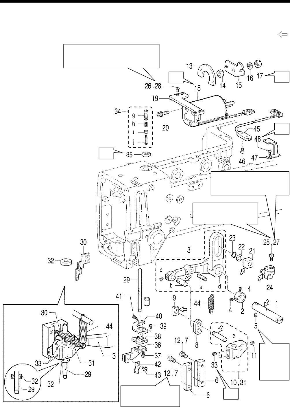
6. ASSEMBLY
HE-800B
64
6-7. Cutter mechanism
* Refer to the detailed descriptions on the next page for details on A to E in the illustration.
* Apply the grease specified by Brother (Power Knock WB2 from JX Nippon Oil & Energy) in the places indicated by .
A
B
E
C
D
Check that the plunger of the cutter
solenoid (18) moves easily along the full
length of its stroke.
Tighten so that the cutter
solenoid shaft is aligned
with the edge.
Check that the plunger of the
cutter solenoid (18) moves easily
along the full length of its stroke.
0712D
Tighten
so that
there is
no play in
the thrust
direction.
Tighten so that it moves
smoothly up and down
with no play.
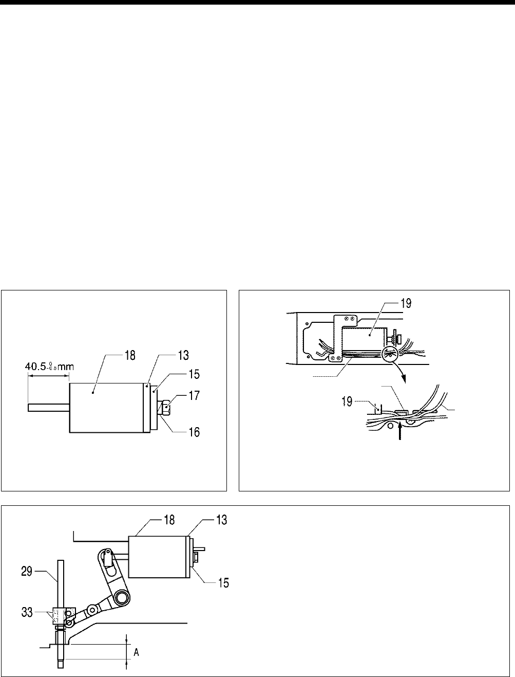
6. ASSEMBLY
HE-800B
65
1. Cutter driving arm shaft
2. Set screw collar
3. Cutter driving arm assembly
4. Set screws [2 pcs]
5. Set screw
6. Cutter bar guide [2 pcs]
7. Screws [4 pcs] (Temporarily
tighten)
8. Cutter driving link
9. Needle bar guide slide block
10. Cutter driving shaft holder
11. Set screw
12. Screws [4 pcs] (Fully tighten)
13. Stopper cushion
14. Nut
15. Solenoid stopper
16. Spring washer
17. Nut
18. Cutter solenoid
19. Cutter solenoid bracket
20. Bolts [3 pcs]
21. Slide block
22. Washer
23. Retaining ring
24. Cutter link bracket
25. Bolt (Temporarily tighten)
26. Screws [4 pcs] (Temporarily
tighten)
27. Bolt (Fully tighten)
28. Screws [4 pcs] (Fully tighten)
29. Cutter driving shaft
30. Felt
31. Cutter driving shaft holder
32. Oil rejector
33. Set screws [2 pcs]
(Temporarily tighten)
34. Adjusting screw assembly
35. Nut
36. Cutter holder DM
37. Screws [2 pcs]
38. Cutter holder M
39. Bolts [2 pcs]
40. Cutter holder
41. Bolt
42. Cutter
43. Screw
44. Spring
45. Cutter sensor
46. Screw
47. Cutter sensor setting plate
48. Screw
a. Pin, dowel
b. Pin
c. Set screw
d. Cutter driving arm
e. Cutter driving link shaft
f. Cutter driving shaft holder
g. Adjusting screw
h. Cushion spring
i. Cushion support
j. Shoulder screw
A
B
Insert the oil tube and the cord of the cutter solenoid (19) in
between tube support U and the arm.
C
Tighten the two set screws (33) so that the distance A
between the processed surface of the arm and the end of
the cutter driving shaft (29)
is 24.5 mm when the cutter
solenoid (18)
is at the stroke end (when the solenoid
stopper (15) is touching the stopper cushion (13)).
*
Lift up the cutter driving shaft by hand at this time and
check that it moves by its own weight. If it does
not move, loosen the socket bolt (27) and the screw (28)
and readjust the cutter driving shaft so that it moves
easily.
0685D
0686D
Oil tube
Tube support U
Oil tube
Insert
0689D
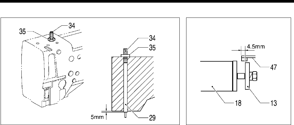
6. ASSEMBLY
HE-800B
66
D
E
0688D 0690D
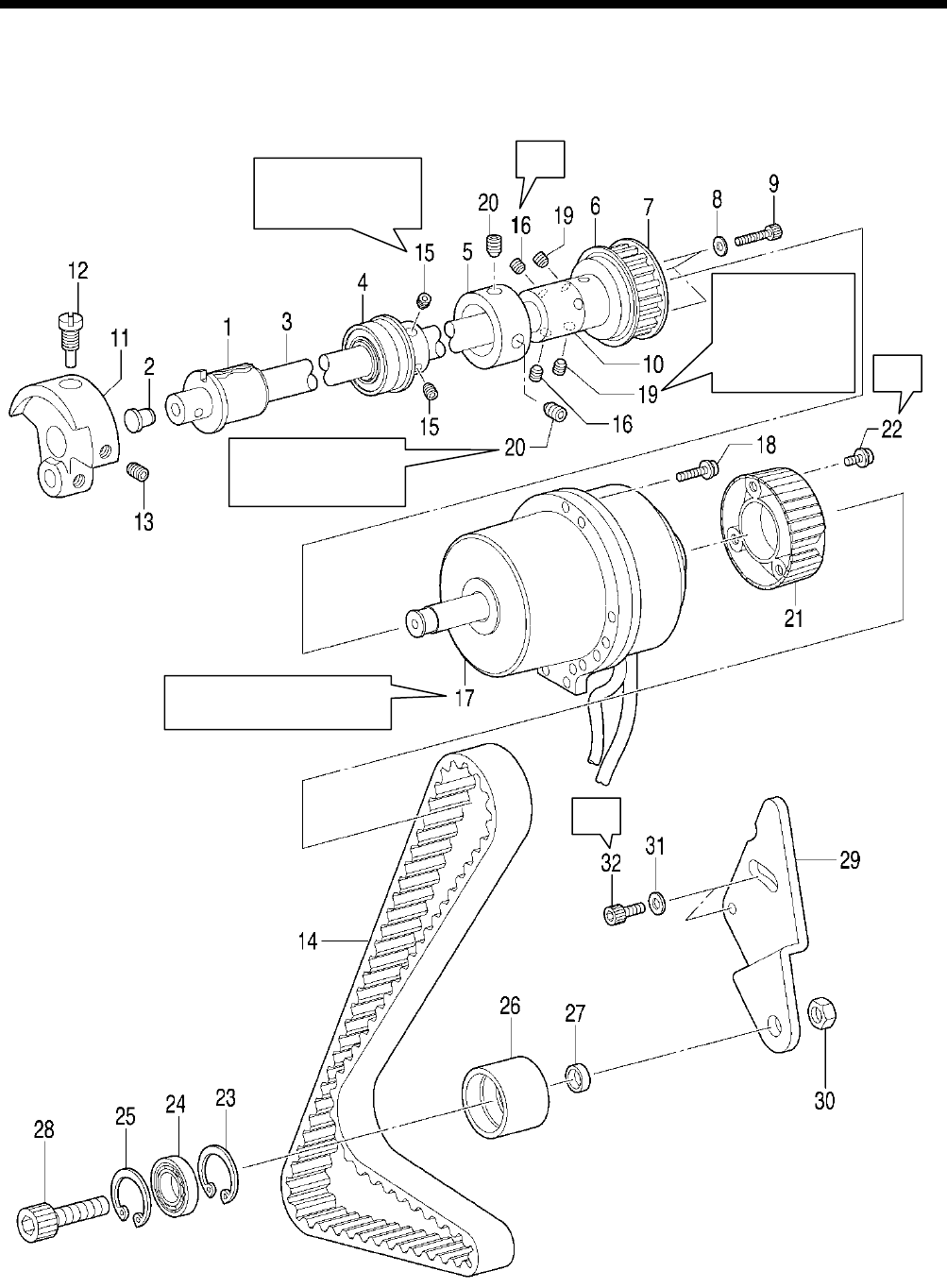
6. ASSEMBLY
HE-800B
67
6-8. Upper shaft and tension pulley mechanisms
* Refer to the detailed descriptions on the next page for details on A to B in the illustration.
A
B
B
Tighten (15) so that
there is no play in
the thrust direction.
Align the screw at
the front in the
turning direction
with the screw stop
on (3)
, and then
tighten the screw.
0713D
Touch against the
edge of (10) and then
tighten.
Set so that the harnesses are
pointing directly downward.
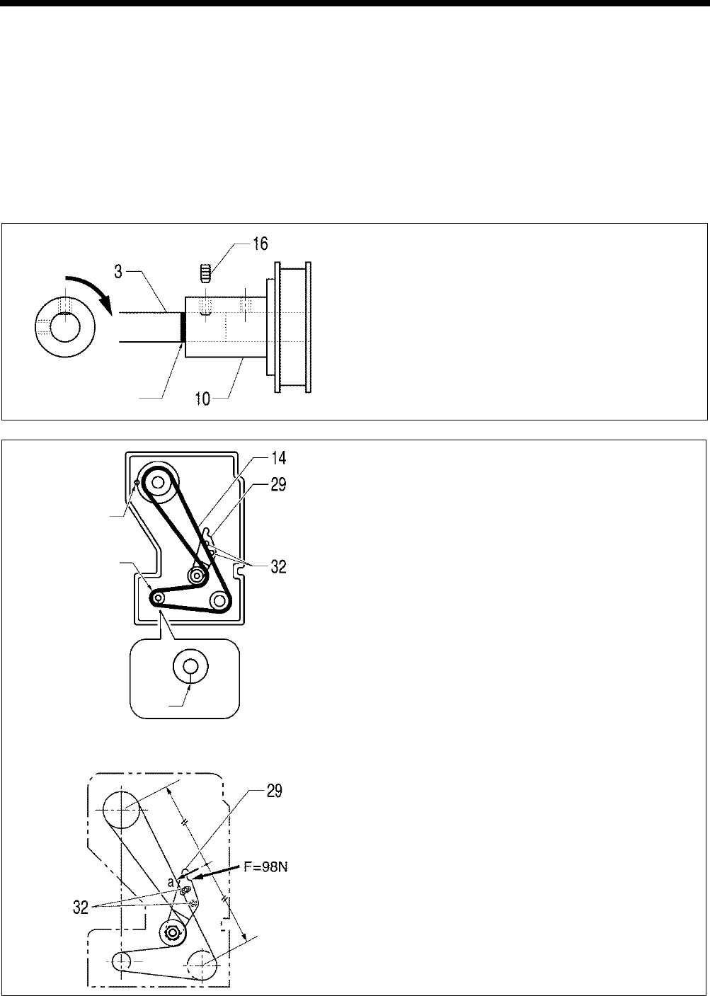
6. ASSEMBLY
HE-800B
68
1. Bush F
2. Cap
3. Upper shaft
4. Bearing bush assy
5. Bobbin winder pulley
6. Flange
7. Timing pulley U
8. Washers [3 pcs]
9. Socket bolts [3 pcs]
10. Joint
11. Thread take-up crank
12. Screw
13. Set screw
14. Timing belt
15. Set screws [2 pcs]
16. Set screws [2 pcs]
17. Motor
18. Screws [3 pcs]
19. Set screws [2 pcs]
20. Set screws [2 pcs]
21. Pulley
22. Screws [3 pcs]
23. Retaining ring
24. Bearing
25. Retaining ring
26. Tension pulley
27. Collar
28. Socket bolt
29. Tension pulley plate
30. Nut
31. Plain washers [2 pcs]
32. Socket bolts [2 pcs]
A
Align the reference line on the upper shaft (3) and the edge of
the joint (10), and then tighten the set screw (16) which is at
the front in the turning direction so that it is aligned with the
screw stop on the upper shaft (3).
B
After installing the needle bar as described in “6-10. Needle
bar and thread take-
up mechanisms”, install these parts so
that the mating mark on the pulley is on the left when viewed
from the rear of the sewing machine when the upper shaft (3)
is at the needle up stop position.
Align the phases of the upper shaft and lower shaft so that
the mating mark A on the lower shaft timing pulley is pointing
straight down when the upper shaft pulley is as described
above, and then adjust the belt tension.
<Belt tension adjustment>
1)
Push the tension pulley plate (29) in the direction of the arrow
to adjust the belt tension to the value range given below.
・ When using a new belt: 75 - 85 N
・ When reusing an old belt: 65 - 75 N
* Re-check at
this time to make sure that the upper shaft and
lower shaft are not out of phase.
*
Be sure to use a belt tension gauge to measure the belt
tension, and measure at position a shown in the illustration.
* The belt tension gauge should be set to measure a unit
weight of 0.25 gf/cm, a belt width of 15 mm and a span
length of 228 mm.
[Reference] If no belt tension gauge is available, use a push pull
gauge to apply 98 N of force to the tension pulley plate
(29) to push it in the direction of the arrow, and then
tighten the two socket bolts (32).
0692D
Aligned with reference
line
0693D
Upper shaft pulley
mating mark
A
0694D
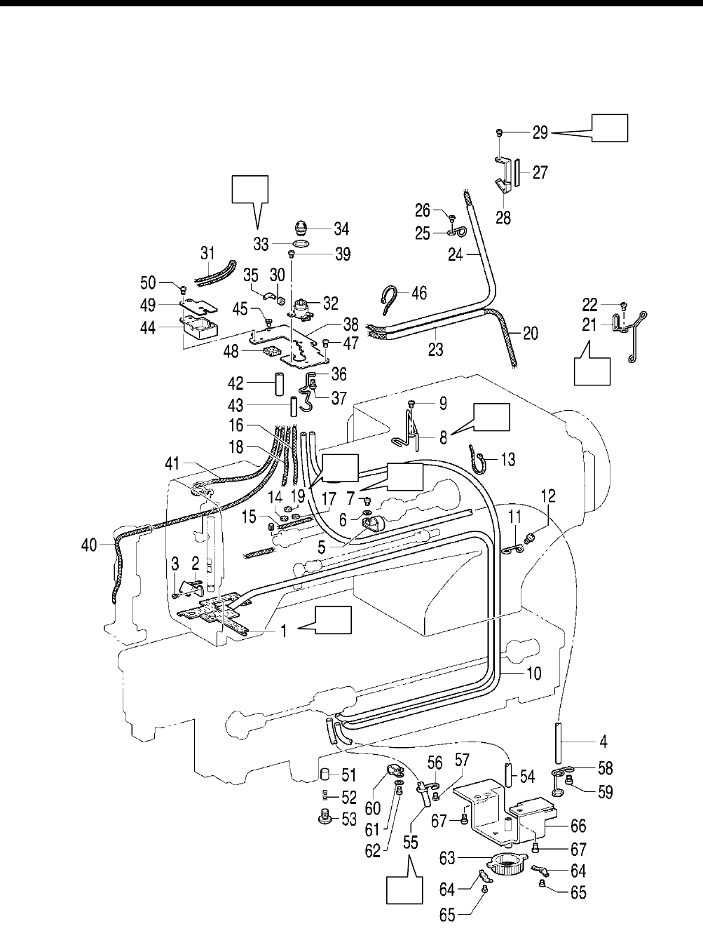
6. ASSEMBLY
HE-800B
69
6-9. Lubrication mechanism
* Refer to the detailed descriptions on the next page for details on A to H in the illustration.
* Carry out the steps from (1) through to (13) in “6-4. Threading mechanism”.
0714D
G
A
F
E
H
B
D
C
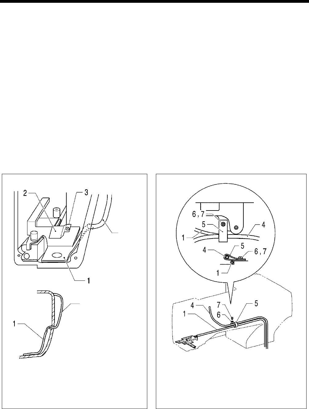
6. ASSEMBLY
HE-800B
70
1. Oil tube assembly
2. Felt holder
3. Screw
4. Oil tube
5. Cord holder #5
6. Plain washer
7. Screw
8. Tube support, R
9. Screw
10. Oil tube
11. Tube support M
12. Screw
13. Fastening bands 1.9×80
14. Felt
15. Wick 4×50
16. Wick 3×150
17. Felt
18. Wick 3×160
19. Felt
20. Wick 4×50×330
21. Tube support U
22. Screw
23. Oil tube
24. Oil tube
25. Tube support
26. Screw
27. Felt
28. Felt support
29. Screw
30. Collar
31. Wick 2×140
32. Oil terminal
33. Packing
34. Oil cap
35. Oil pipe B
36. Tube support
37. Screw
38. Wick base support
39. Screws [2 pcs]
40. Wick 3×290
41. Wick
42. Oil tube
43. Oil tube
44. Felt base A
45. Screw
46. Fastening bands 1.9×80
47. Screws [2 pcs]
48. Felt
49. Cap
50. Screw
51. Plunger [2 pcs]
52. Compression spring [2 pcs]
53. Screws [2 pcs]
54. Oil tube
55. Oil tube
56. Tube support
57. Screw
58. Tube support D
59. Screw
60. Cord holder #10
61. Plain washer
62. Screw
63. Pump filter
64. Spring [2 pcs]
65. Screws [2 pcs]
66. Oil filter mounting plate assy
67. Screws [3 pcs]
A
1) Insert the oil tube assembly (1) into the arm, and
then insert it into the hole in the thread take-up
cover.
2)
Install the felt holder (2) with the screw (3), and then
secure the oil tube assembly (1).
B
1) Install the oil tube (4) that is connected between the oil
terminal and the oil outlet with the cord holder (5),
screw (7) and washer (6).
2)
Clamp the oil tube assembly (1) under the cord holder
(5).
Thread
take-up
cover
Thread take-up cover
0695D 0696D
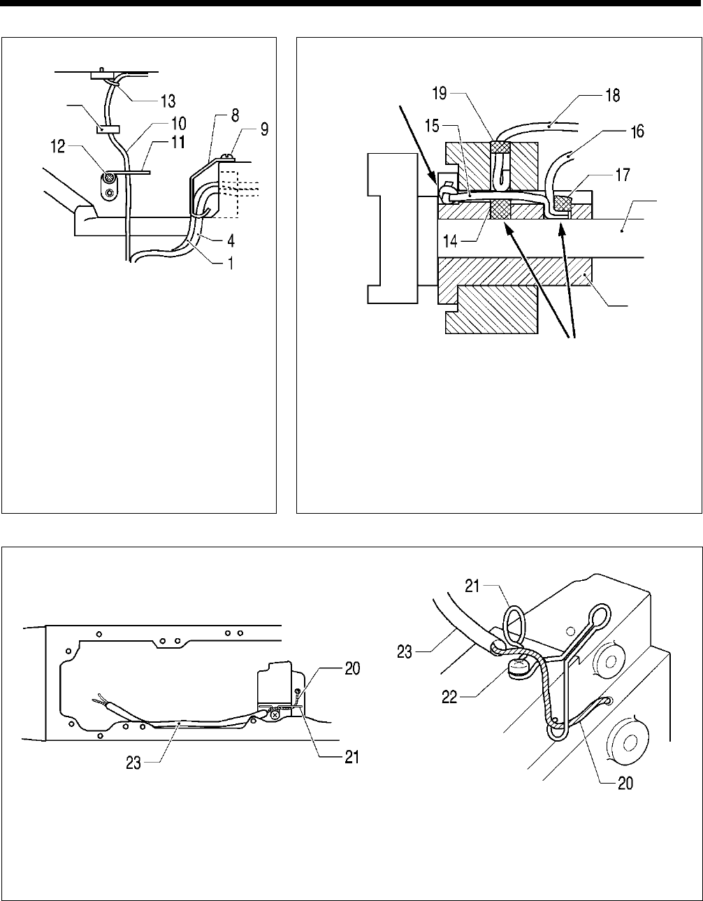
6. ASSEMBLY
HE-800B
71
C
1)
Install the tube support (8) with the screw
(9), and then secure the oil assembly (1)
and the oil tube (4) that is connected
between the oil terminal and the oil outlet
so that they do not touch the pulse motor
(for presser lifter).
2) Install the oil tube (10) that is connected to
the oil terminal and the plunger pump with
the tube support M (11) and the screw
(12), pass it through the arm hole, and
then secure it to the arm with the fastening
band (13).
* At this time, bind the oil tube carefully so
as not to break it.
D
1) Insert the felt (14) into the bush F.
2)
Insert the wicks (15) and (16) into the bush F, and insert the felt
(17) to stop them from coming out.
* At this time, push in firmly so that the felt (14) and the wick (15)
are touching the upper shaft. If they are not pushed in firmly
enough, seizure of the upper shaft may occur.
3)
Insert the wick (18) into the bush F, and insert the felt (19) to stop
them from coming out.
E
1) Pass the wick (20) through the tube support U (21) and push it firmly into the zigzag lever shaft lubrication hole.
2) Install the tube support U (21) with the screw (22).
3) Pass the oil tube (23) around the outside of the tube support U (21) as shown in the illustration.
0699D
0700D
Wick should not
protrude
from here
Upper
shaft
Bush F
Push so they touch
the upper shaft
0698D
0697D
Arm hole
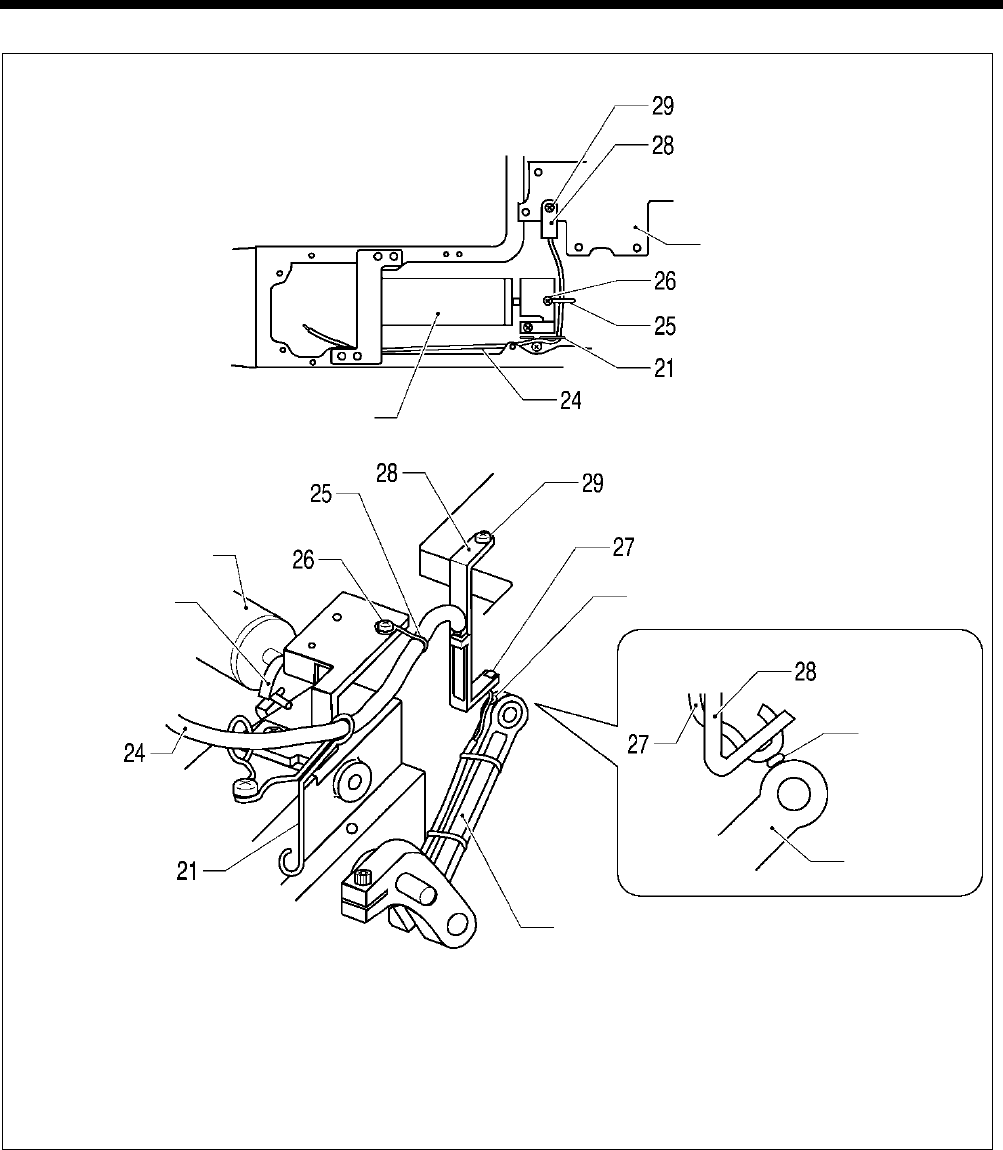
6. ASSEMBLY
HE-800B
72
F
1)
Pass the oil tube (24) through the tube support U (21) and the tube support (25), and then secure the tube support (25)
with the screw (26).
2) Install the felt support (28) to the motor bracket with the screw (29) at the position where the felt (27) and the felt of the
zigzag connecting rod are gently touching.
3)
Pass the oil tube (24) around the outside of the tube support U (21) as shown in the illustration so that it does not touch
the solenoid stopper, and then pass it in between the cutter solenoid and the arm.
0701D
0702D
Motor bracket
Cutter solenoid
Felt
Zigzag connecting rod
Solenoid
stopper
Cutter solenoid
Felt
Zigzag
connecting
rod
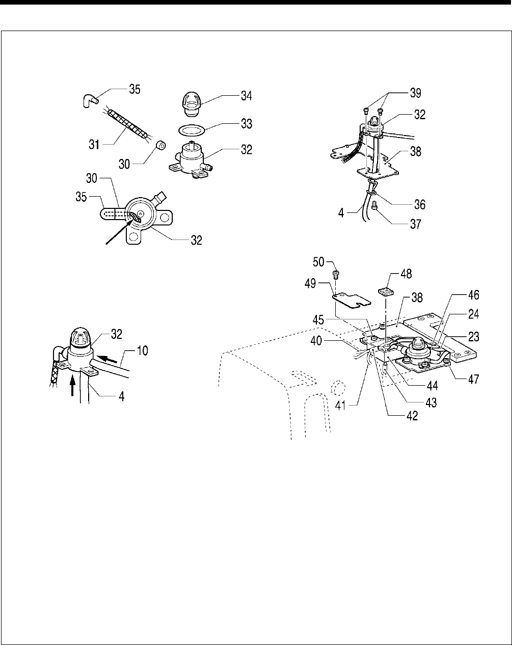
6. ASSEMBLY
HE-800B
73
G
1) Pass the wick (31) through the collar (30), and then insert it into the oil terminal (32). Push the wick (31) firmly enough
into the groove as shown in the illustration.
2) Insert the packing (33) into the oil terminal (32), and then install the oil cap (34).
3) Pass the wick (31) through the oil pipe B (35), and then install it to the oil terminal (32).
4) Push the oil tube (10) that is connected between the oil terminal and the plunger pump into the oil terminal (32).
5) Push the oil tube (4) that is connected between the oil terminal and the oil outlet into the oil terminal (32).
6) Install the tube support (36) to the wick base support (38) with the screw (37).
7) Attach the oil tube (4) to the tube support (36), and then install the oil terminal (32) to the wick base support (38) with the
two screws (39).
8) Pass the wick (40) of the needle bar bracket, the two wicks of the bush F, and the wick 41 coming from the thread
take-up support shaft through the oil tubes (42) and (43), and then install the wick base A (44) to the wick base support
(38) with the screw (45).
9) Install the oil tube (24) for lubricating the bush M and the zigzag lever shaft and the oil tube (23) for lubricating the
zigzag mechanism to the wick base support (38) with the fastening band (46).
10) Install the wick base support (38) with the two screws (47).
11
)
Insert the felt (48), and then install the cap (49) with the screw (50).
Push into the groove
0704D
0705D
0703D
0706D
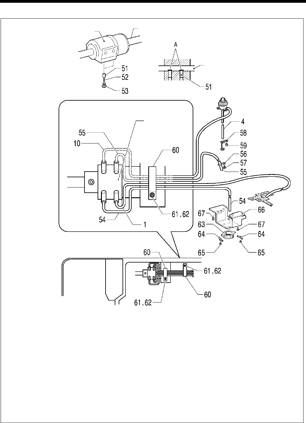
6. ASSEMBLY
HE-800B
74
H
1)
Check that the notches A of the plungers (51) and the lower shaft are aligned, and then insert the two plungers (51)
and the compression springs (52) into the bush M and secure them with the two screws (53).
2) Insert the oil tube (1) into the lubricating hole to the right of the bush M.
3) Insert the oil tube (54) that is connected between the plunger and the filter into the lubricating hole to the left of the
bush M.
4) Insert the oil tube (55) into the lubricating hole to the right of the bush M.
5)
Pass the outlet of the oil tube (55) through the tube support (56), and then install the tube support (56) to the bed with
the screw (57).
6)
Insert the oil tube (10) that is connected between the oil terminal and the plunger pump through the lubricating hole to
the left of the bush M.
7) Pass the oil tube (4) that is connected between the oil terminal and the oil outlet through the tube support D (58), and
then install the tube support D (58) to the bed with the screw (59).
8)
Secure the four tubes that are coming out from the bush M to the bed in two places as shown in the illustration with the
cord holders (60), screws (62) and plain washers (61).
9) Install the pump filter (63) to the oil filter bracket (66) with the two springs (64) and the two screws (65).
10) Insert the oil tube (54) that is connected between the plunger and the filter through the oil filter bracket (66).
11
)
Install the oil filter bracket (66) to the bed with the three screws (67).
0774D
0668D
Bush M Lower shaft
Lower shaft
Bush M
0773D
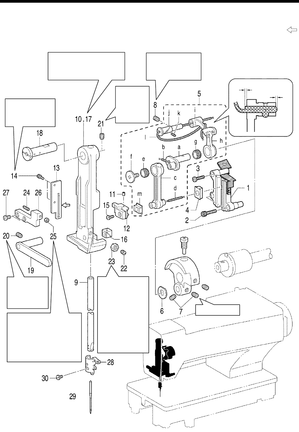
6. ASSEMBLY
HE-800B
75
6-10. Needle bar and thread take-up mechanisms
* Apply the grease specified by Brother (Power Knock WB2 from JX Nippon Oil & Energy) in the places indicated by .
0715D
Tighten so that the
thread take-up moves
smoothly with no
play.
Screw stop side
Tighten so that
there is no play
in the needle
bar bracket
assy.
Insert the needle bar (9) into the
arm, and then install the needle
bar bracket while clamping the
slide blocks (12) and (16).
Tighten so that the
needle bar moves
smoothly.
Tighten so
that there is
no play in
the needle
bar bracket
assy.
When the needle bar (9) is at
its maximum zigzag position,
tighten the set screws (22) and
(24) against the needle bar
bracket assembly (17), and
then loosen them again by
about 1/4 of a turn each. Then
tighten the nuts (23) and (25).
When the needle
bar (9
) is at
its maximum zigzag
position, tighten the
set screws (22) and
(24)
against the
needle bar bracket
assembly (17), and
then loosen them
again by about 1/4
of a turn each. Then
tighten the nuts (23)
and (25).
1.0 to 2.0 mm
0.5 to 1.5 mm

6. ASSEMBLY
HE-800B
76
1. Crank rod guide
2. Socket bolts [2 pcs]
3. Screw
4. Needle bar guide slide block
5. Needle bar connecting rod
assembly
6. Washer
7. Set screws [2 pcs]
8. Set screw
9. Needle bar
10. Needle bar bracket
11. Felt
12. Needle bar clamp assembly
13. Needle bar guide
14. Set screws [2 pcs]
15. Screw
16. Slide block
17. Needle bar bracket
18.
Needle bar bracket support
shaft
19. Needle bar bracket guide
20. Set screw
21. Set screw
22. Set screw
23. Nut
24. Set screw
25. Nut
26. Stopper
27. Screws [2 pcs]
28. Needle bar thread guide
29. Needle
30. Set screw
a. Needle bar crank
b. Wick
c. Needle bar connecting rod
d. Wick
e. Needle bearing
f. Screw (Left-hand thread)
g. Needle bearing
h. Thread take-up lever
i. Thread take-up support
j. Support shaft
k. Felt
l. Wick
m. Slide block
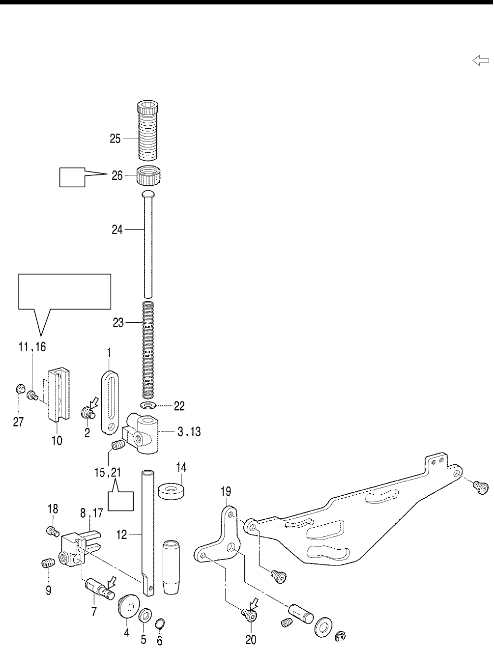
6. ASSEMBLY
HE-800B
77
6-11. Presser bar mechanism
* Refer to the detailed descriptions on the next page for details on A to E in the illustration.
* Apply the grease specified by Brother (Power Knock WB2 from JX Nippon Oil & Energy) in the places indicated by .
B
Tighten so that the
presser bar moves
smoothly.
A
0716D
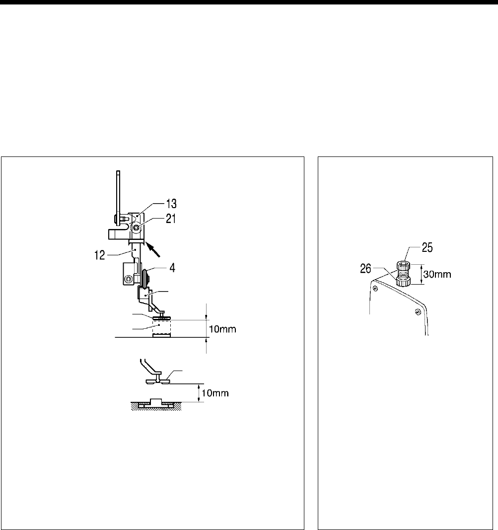
6. ASSEMBLY
HE-800B
78
1. Presser bar lifter link
2. Shoulder screw
3. Presser bar guide bracket
4. Roller
5. Plain washer
6. Retaining ring
7. Roller shaft
8. Presser roller bracket
9. Set screw
10. Needle bar guide
11. Screws [2 pcs] (Temporarily
tighten)
12. Presser bar
13. Presser bar guide bracket
14. Oil rejector
15. Set screw (Temporarily
tighten)
16. Screws [2 pcs] (Fully tighten)
17. Presser roller bracket
18. Screw
19. Knee lifter lever
20. Shoulder screw
21. Set screw
22. Washer
23. Compression spring
24. Spring guide
25. Presser adjusting screw
26. Presser adjusting nut
27. Rubber caps [2 pcs]
A
1) Place a 10 mm gauge underneath the work clamp.
2) Turn on the power, move the feed mechanism to the home position,
and then check that memory switch No. 002 (Work clamp height
when treadle is at neutral) is 10 mm. (If it is not set to 10 mm, set it to
10 mm.)
3)
While pushing the presser bar (12) down from above, tighten the set
screw (21) so that the roller (4) is not at an angle to the V-shaped
groove in the presser arm .
4
)
Remove the gauge and turn off the power.
B
Insert the spring guide (24), compression
spring (23) and plain washer (22), and
with the presser adjusting screw (25) at a
height of 30 mm, tighten the presser
adjusting nut (26).
0717D
Work clamp
Install with (14) at the
0718D
Gauge (10mm)
Work clamp
Presser arm
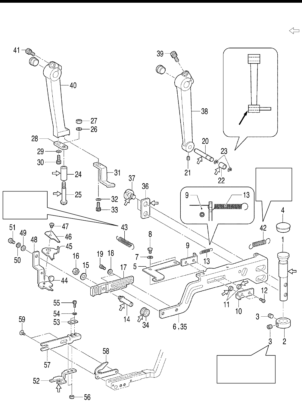
6. ASSEMBLY
HE-800B
79
6-12. Upper thread trimmer mechanism
* Apply the grease specified by Brother (Power Knock WB2 from JX Nippon Oil & Energy) in the places indicated by .
0719D
Tighten so that the
upper thread trimmer
fulcrum shaft (1) turns
smoothly.
Align edges
Attach the larger
hook of the
spring to the pin
on the arm.
Attach the
larger hook
of the spring
to the pin on
the arm.
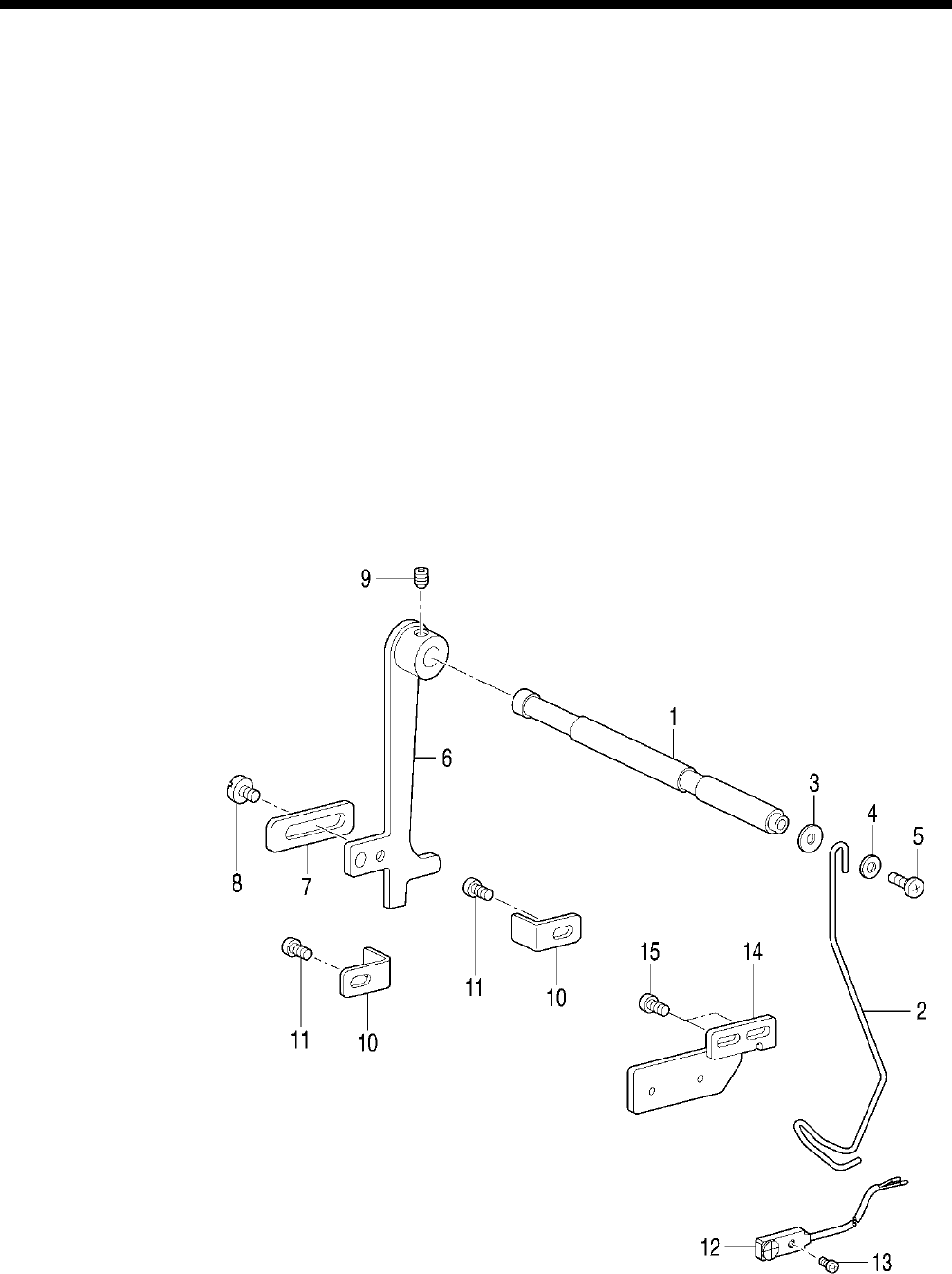
6. ASSEMBLY
HE-800B
80
1. Upper thread trimmer fulcrum
shaft
2. Set screw collar
3. Set screw [2 pcs]
4. Rubber cap
5. Adjusting plate
6. Upper thread trimmer lever
7. Washers [2 pcs]
8. Bolts [2 pcs]
9. Stop plate
10. Back plate
11. Collar [2 pcs]
12. Screws [2 pcs]
13. Spring
14. Support shaft
15. Plain washer
16. Nut
17. Setting plate
18. Plain washers [2 pcs]
19. Screws [2 pcs] (Temporarily
tighten)
20. Longitudinal feed arm pin
21. Set screw
22. Longitudinal feed arm roller
23. Retaining rings [2 pcs]
24. Driving arm roller
25. Roller shoulder screw
26. Spring washer
27. Nut
28. Support plate
29. Plain washer
30. Bolt (Temporarily tighten)
31. Back stopper
32. Plain washer
33. Bolt (Temporarily tighten)
34. Roller
35.
Upper thread trimmer lever
assembly
36. Washer
37. Screws [2 pcs]
38. Longitudinal feed arm assembly
39. Bolt (Temporarily tighten)
40. Trimmer driving arm
41. Bolt (Temporarily tighten)
42. Extension spring
43. Extension spring
44. Stopper
45. Scissors M
46. Scissors U
47. Shoulder screw, SM3.18
48. Thread trimmer assy D
49. Plain washer
50. Spring washer
51. Screw (Temporarily tighten)
52. Opening cam
53. Washer plain
54. Spring washers [2 pcs]
55. Set screws [2 pcs]
56. Nuts [2 pcs]
57. Cam setting plate
58. Feed arm support
59. Screws [2 pcs] (Temporarily
tighten)
6-13. Thread breakage detector mechanism
1. Thread breakage perceiving
shaft
2. Thread guide
3. Plain washer
4. Plain washer
5. Screw
6. Cutter bar fixed plate
7. Balancer
8. Screw
9. Set screw (Temporarily tighten)
10. Lever stopper [2 pcs]
11. Screws [2 pcs] (Temporarily
tighten)
12. Sensor
13. Screw
14. Thread breakage sensor plate
15. Screws [2 pcs] (Fully tighten)
0721D
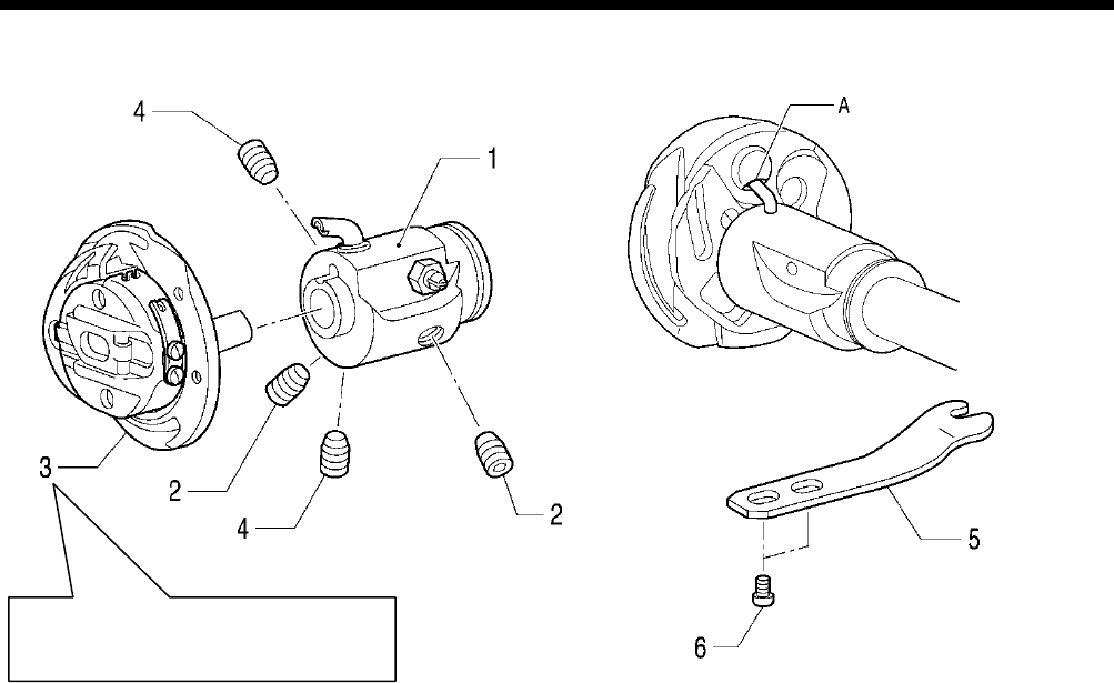
6. ASSEMBLY
HE-800B
81
6-14. Rotary hook mechanism
1. Rotary hook joint assembly
2. Set screw [2 pcs] (Provisionally
tighten)
3. Rotary hook
4. Set screw [2 pcs] (Provisionally
tighten)
Adjust the needle clearance and
timing. (Refer to “7-
4. Adjusting the
needle and rotary hook timing”.)
5. Rotary hook holder
6. Screws [2 pcs]
4279Q
0723D
Screw stop side
Tighten the set screw (4) so that the oil inlets
A in the rotary hook (3) and the rotary hook
joint assembly (1) are aligned.
0722 D
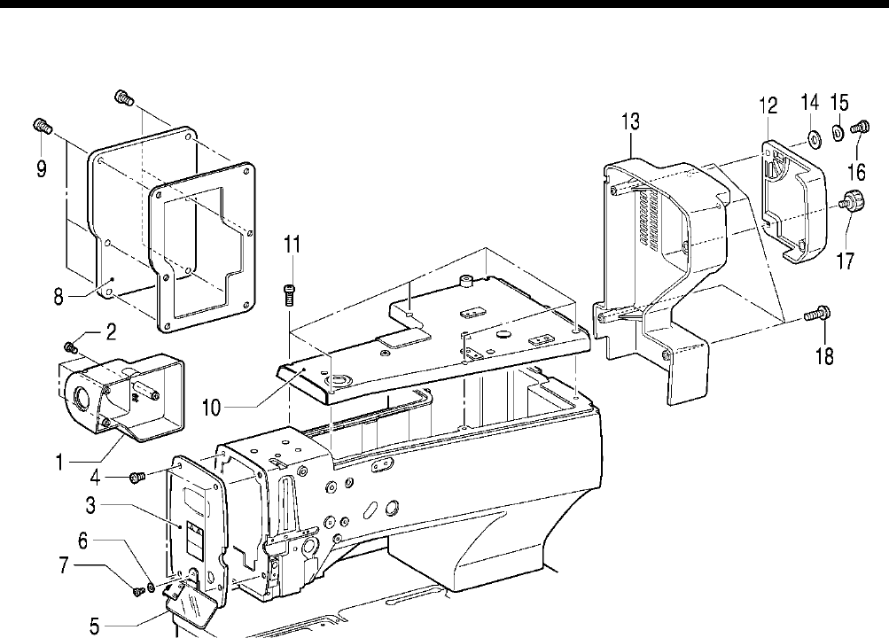
6. ASSEMBLY
HE-800B
82
6-15. Covers
1. Cover
2. Screws [3 pcs]
3. Main plate
4. Screws [4 pcs]
5. Eye guard assembly
6. Washer
7. Screw
8. Rear cover
9. Screws [6 pcs]
10. Top cover
11. Screws [6 pcs]
12. Slide cover
13. Motor cover
14. Washer
15. Wave washer
16. Shoulder screw
17. Knob screw
18. Screws [4 pcs]
0725D
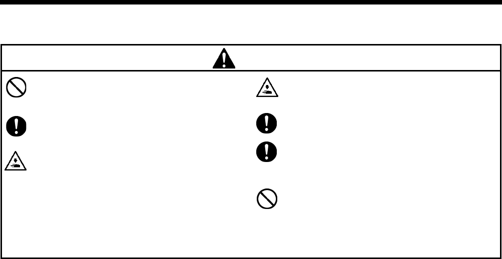
7. ADJUSTMENT
HE-800B
83
7. ADJUSTMENT
CAUTION
Maintenance and inspection of the
sewing machine should only be carried out by a
qualified technician.
Ask your Brother dealer or a qualified
electrician to carry out any maintenance and
inspection of the electrical system.
Turn off the power switch and disconnect the
power cord from the wall outlet at the following
times, otherwise the machine may operate if
the treadle is depressed by mistake, which
could result in injury.
•
When carrying out inspection, adjustment
and maintenance
• When replacing consumable parts such as
the rotary hook
If the power switch needs to be left on when
carrying out some adjustment, be extremely
careful to observe all safety precautions.
Use only the proper replacement parts as
specified by Brother.
If any safety devices have been removed, be
absolutely sure to re-
install them to their
original positions and check that they operate
correctly before using the machine.
Any probl
ems in machine operation which
result from unauthorized modifications to
the machine will not be covered by the
warranty.
7-1. Notes on making adjustments
[When turning on the power to make adjustments]
Turn on the power and set the sewing machine to the home position. Then press the THREAD key to lower the work clamp
before carrying out adjustments.
“Threading” will appear in the parameter display LED and the sewing machine will not operate even if the treadle is depressed.
* Some items are adjusted without the THREAD key being pressed. Carry out the adjustment by following the explanations
given.
[When turning off the power to make adjustments]
Do not force any of the parts to move, as doing so may result in damage to the parts.
• Be sure to turn the machine pulley to raise the needle bar to its highest position before making adjustments.
If this is not done, the pulley position (the direction of rotation of the rotary hook) may cause the lower thread
trimmer mechanism to touch the rotary hook when the lower thread trimmer mechanism operates.
• When turning the machine pulley, do it at a position where the thread trimmer mechanism will not operate (the position where
the presser foot lifter pulse motor is at the home position).
If the machine pulley is turned at a position where the thread trimmer mechanism operates, the needle may touch the lower
thread trimmer mechanism (lower thread retainer and lower thread trimmer knife).
If the machine pulley is turned at a position where the thread trimmer mechanism operates, the rotary hook and the lower
thread trimmer mechanism may touch.
• When moving the feed mechanism, do it at a position where the thread trimmer mechanism will not operate (the position
where the presser foot lifter pulse motor is at the home position).
If this is not done, the lower thread retainer and the feed guide shaft may alternately push against the lower thread clamp
and the opening plate, and damage may result.
• When pushing the knife down by hand, be careful not to let it touch the upper thread scissors.
• Do not move the feed mechanism while the stop plate of the upper thread trimmer lever is pulled forward and the upper
thread scissors are open (the upper thread trimmer lever is pushed to the left).
Always return the stop plate to its original position before moving the feed mechanism or returning it to the home position.
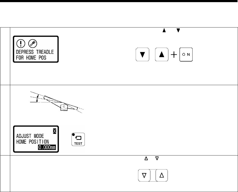
7. ADJUSTMENT
HE-800B
84
7-2. Adjusting the home position
7-2-1. Switching to home position adjustment mode
1
While pressing the and keys simultaneously, turn on
the power switch.
• The home position detection screen for switching to
adjustment mode will be displayed.
2
Depress the treadle to the 2nd step (for a triple pedal,
depress the start switch).
• Home position detection will be carried out, and then the
sewing machine will switch to needle
zigzag motor
home position adjustment mode.
•
When the sewing machine has switched to home
position adjustment mode, the TEST indicator will flash.
3
Select the home position menu.
Press the or key.
2nd step
Flashing
0812D
0813D
0727D
0630D
4441Q
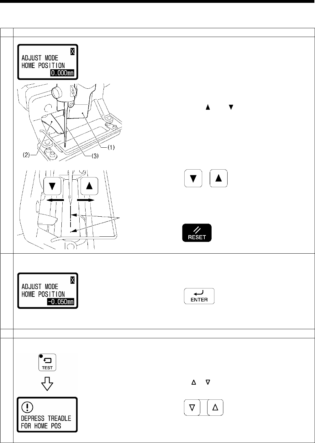
7. ADJUSTMENT
HE-800B
85
7-2-2. Needle zigzag (X) motor home position
1
Select the “X” home position adjustment mode.
2
1. Move the feed arm forward by hand so that the cutter (1)
is not touching the scissors (2), and then move the
scissors (2) to the left.
2. Place some paper under the work clamp, and then push
the cutter (1) down by hand.
3. Turn the pulley by hand until the tip of the needle (3) drops
to the paper.
4. Press the and
keys to change the offset
(-1.500 mm to 1.500 mm) so that the needle drop position
is aligned with the mark made by the cutter.
• The X motor will operate in accordance with the offset
value.
• The offset value will flash in the display.
* If you press the RESET key for 2 seconds or more at
this time, the offset value will be reset to 0.00 mm and X
home position detection will be carried out.
3
Press the ENTER key to store the offset value.
At this time, X home position detection will be carried out and
the offset value will illuminate steadily in the display.
4
Repeat steps 2 and 3 to set the home position to the correct position.
5
End adjustment mode.
Once home position adjustment operation is finished, press
the TEST key.
• Normal sewing machine operation will then be possible.
To carry out home position adjustment for another motor
Press the or key.
0814D
0730D
0731D
0815D
0732D
0630D
2634B
0747D
0816D
Flashing → Illuminates
Aligned
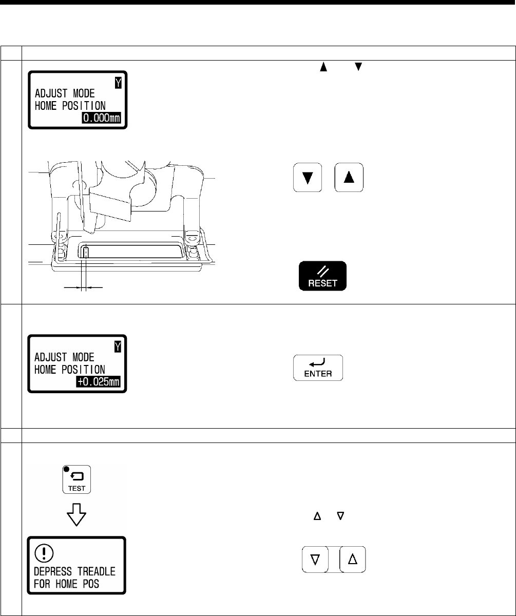
7. ADJUSTMENT
HE-800B
86
7-2-3. Feed (Y) motor home position
1
Select the “Y” home position adjustment mode.
2
Press the and
keys to change the offset value
(-1.500 mm to 1.500 mm) so that the distance A between the
center of the needle hole in the needle plate and the inside
front edge of the work clamp is 1.8 mm.
• The Y motor will operate in accordance with the offset
value.
• The offset value will flash in the display.
* If you press the RESET key for 2 seconds or more at
this time, the offset value will be reset to 0.000 mm and
Y home position detection will be carried out.
3
Press the ENTER key to store the offset value.
At this time, Y home position detection will be carried out and
the offset value will illuminate steadily in the display.
4
Repeat steps 2 and 3 to set the home position to the correct position.
5
End adjustment mode.
Once home position adjustment operation is finished, press
the TEST key.
• Normal sewing machine operation will then be possible.
To carry out home position adjustment for another motor
Press the or key.
0817D
A
0724D
0818D
0732D
2634B
0630D
0747D
0816D
Flashing → Illuminates
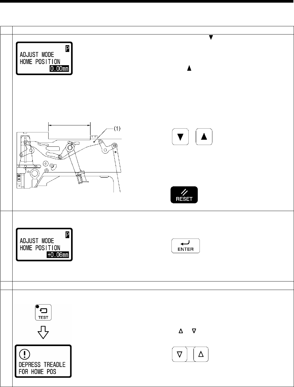
7. ADJUSTMENT
HE-800B
87
7-2-4. Work clamp (P) motor home position
1
Select the “P” home position adjustment mode.
2
1. Keep pressing the key briefly until the panel value
stops changing.
(The upper thread trimmer driving link (1) will
stop moving.)
2. Measure the distance A in the illustration.
3. Press the key to adjust the offset value (-6.82 mm to
1.86 mm) so that the dimension shown in the
illustration moves to the position where it is equal to
distance A + 0.5 mm.
• The P motor will operate in accordance with the offset
value.
• The offset value will flash in the display.
* If you press the RESET key for 2 seconds or more at
this time, the offset value will be reset to 0.00 mm and P
home position detection will be carried out.
3
Press the ENTER key to store the offset value.
At this time, P home position detection will be carried out and
the offset value will illuminate steadily in the display.
4
Repeat steps 2 and 3 to set the home position to the correct position.
5
End adjustment mode.
Once home position adjustment operation is finished, press
the TEST key.
• Normal sewing machine operation will then be possible.
To carry out home position adjustment for another motor
Press the or key.
0819D
A
0737D
0820D
0732D
2634B
0747D
0630D
0816D
Flashing → Illuminates
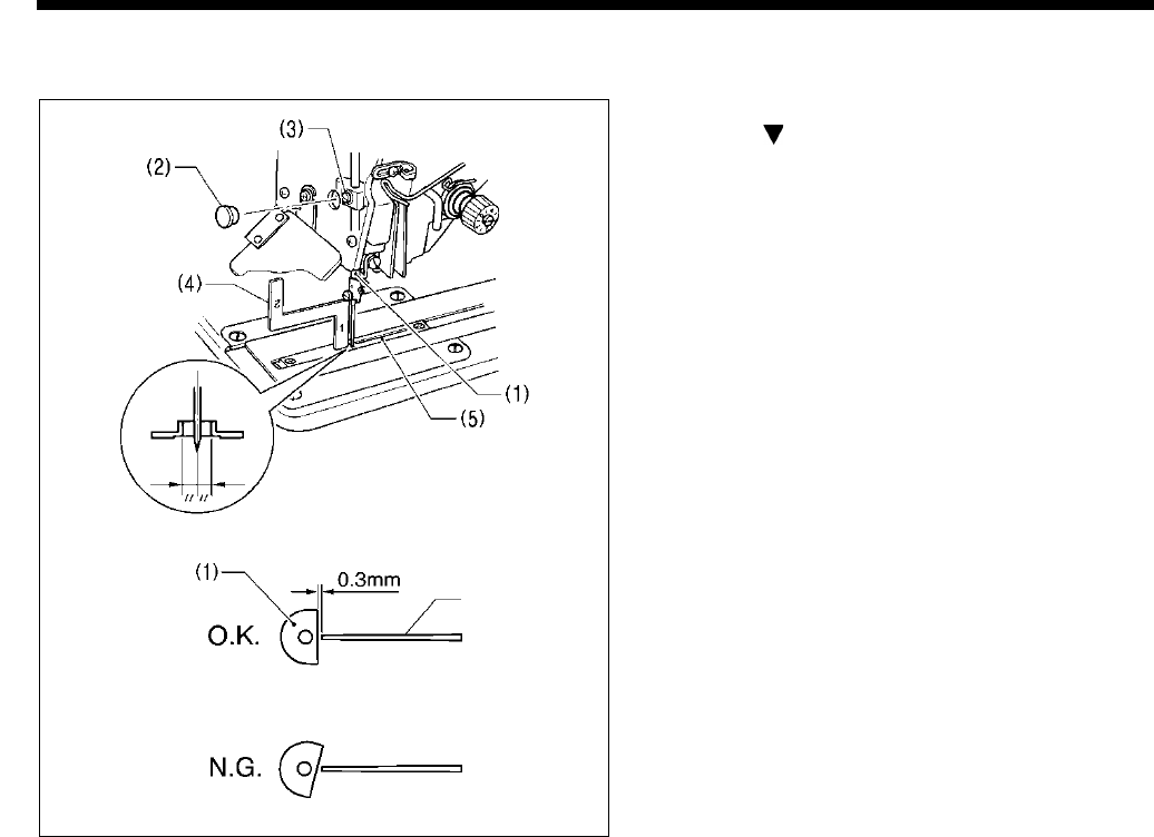
7. ADJUSTMENT
HE-800B
88
7-3. Adjusting the needle bar height
1. Press the THREAD key to switch to threading mode.
2. Press the key.
3. Set the needle bar (1) to its lowest position.
4. Remove the rubber cap (2) from the face plate, and then
loosen the set screw (3) of the needle bar clamp.
5. Insert the “1” part of the gauge (4) between the needle
plate (5) and the lower edge of the needle bar (1), and
touch the needle bar against the gauge.
* Different gauges (optional part) are used for each of
the two specifications -2 and -3, so make sure that the
gauge being used matches the specifications and
application for the sewing machine being adjusted.
6. Tighten the set screw (3).
7. Install the rubber cap (2).
8. Check that the cutter flank of the needle bar (1) is at a
right angle to the cutter.
9. Press the THREAD key.
Note:
If the installation positions are not correct, the needle
bar (1) and the cutter may touch when the needle
zigzags, which may result in noise or cause the needle
to break.
4878M
Cutter
4290Q
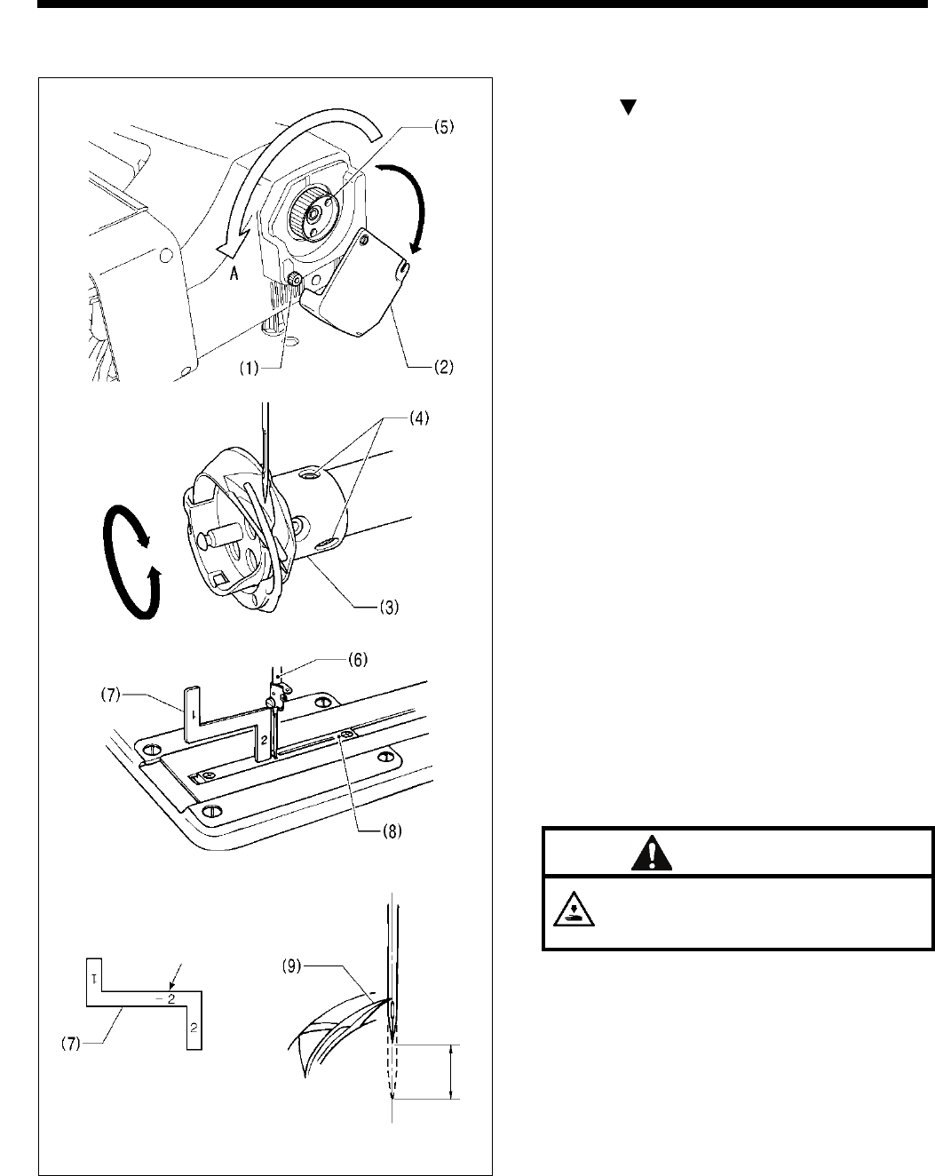
7. ADJUSTMENT
HE-800B
89
7-4. Adjusting the needle and hook timing
1. Press the THREAD key to switch to threading mode.
2. Press the key.
3. Gently tilt back the machine head.
4. Loosen the knob screw (1), and then fully open the
slide cover (2).
5. Loosen the two screws (4) of the rotary hook joint (3).
6. Turn the pulley (5) in the regular direction of rotation
(A: toward the front) so that the needle bar (6) just
begins to rise from its lowest position.
7. Insert the “2” part of the gauge (7) between the needle
plate (8) and the lower edge of the needle bar (6), and
then align the rotary hook tip (9) with the center of the
needle when the needle bar (6) contacts the gauge
(7).
* Different gauges (optional part) are used for each of
the two specifications -2 and -3, so make sure that the
gauge being used matches the specifications and
application for the sewing machine being adjusted.
8. Tighten the two set screws (4) of the rotary hook joint
(3).
9. Close the slide cover (2), and then tighten the screw
(1) to secure it.
CAUTION
Close the slide cover (2) and secure it. The
inner pulley (5) rotates during sewing, so do
not touch it, otherwise injury may occur.
10. Gently return the machine head to its original position.
11. Press the THREAD key.
4880M
4883M
4882M
Mark
4881M
4879M
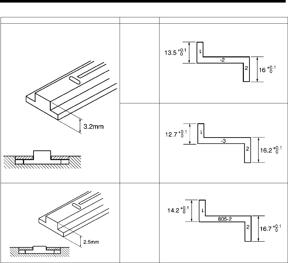
7. ADJUSTMENT
HE-800B
90
Needle plate thickness
Application
Gauge
Clothing
(-2)
Knitted
wear
S13595-001 Gauge 815-2
Knitted
wear
(-3)
S13596-001 Gauge 815-3
Thin knitted
wear
S13597-001 Gauge 805-2
4293Q
4292Q
4296Q
4295Q
4294Q
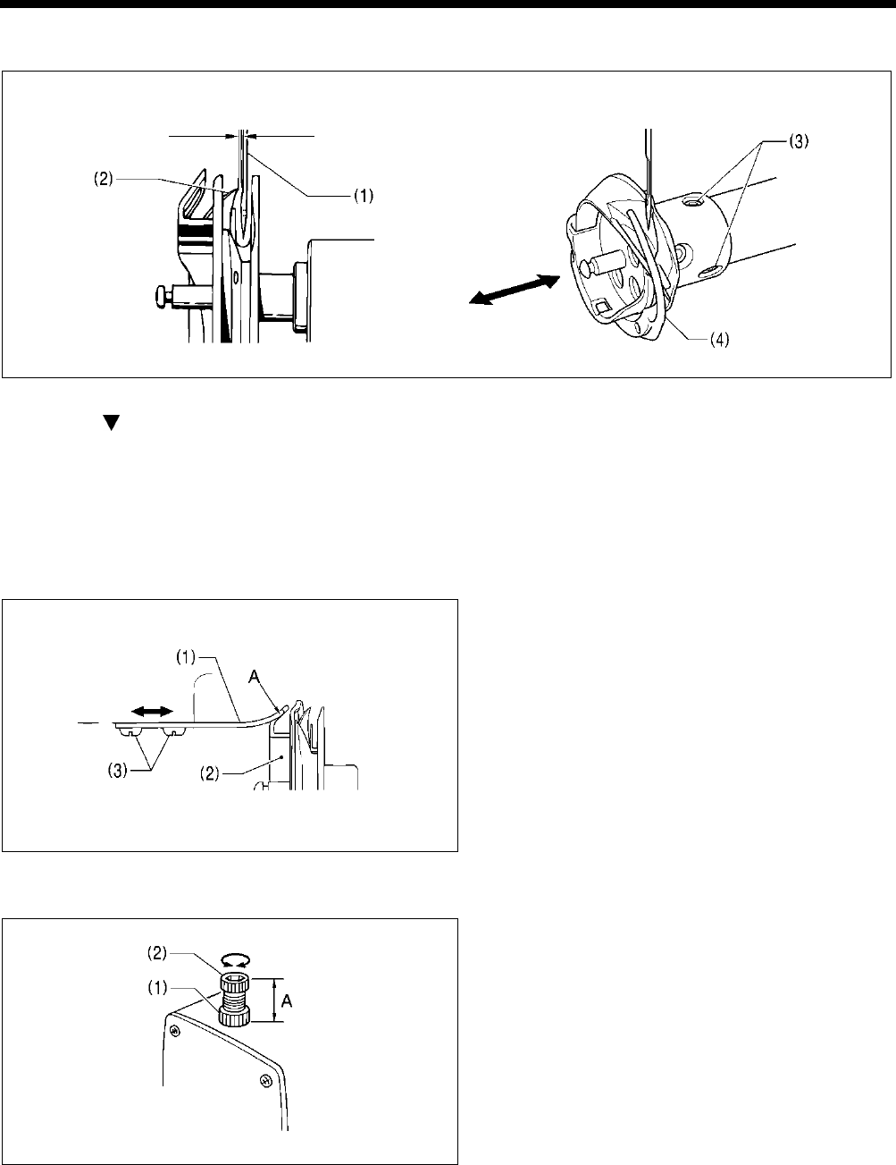
7. ADJUSTMENT
HE-800B
91
7-4-1. Adjusting the clearance between needle and hook tip
1. Press the THREAD key to switch to threading mode.
2. Press the key.
3. Gently tilt back the machine head.
4. Loosen the screws (3) and move the rotary hook (4) forward or back until there is a clearance of 0.01 – 0.08 mm between the
needle (1) and the hook tip (2).
5. Gently return the machine head to its original position.
6. Press the THREAD key.
7-5. Adjusting the inner rotary hook and rotary hook holder overlap
1. Gently tilt back the machine head.
2. Loosen the two screws (3) to adjust so that the tip of
the rotary hook holder (1) does not protrude past the
edge A of the inner rotary hook (2).
3. Gently return the machine head to its original position.
7-6. Adjusting the work clamp pressure
The standard distance A is 30 mm (approximately 30 N).
Loosen the nut (1) and turn the adjusting screw (2) to
adjust the work clamp pressure.
0.01 – 0.08 mm
2839Q
4884M
3977Q
3978Q
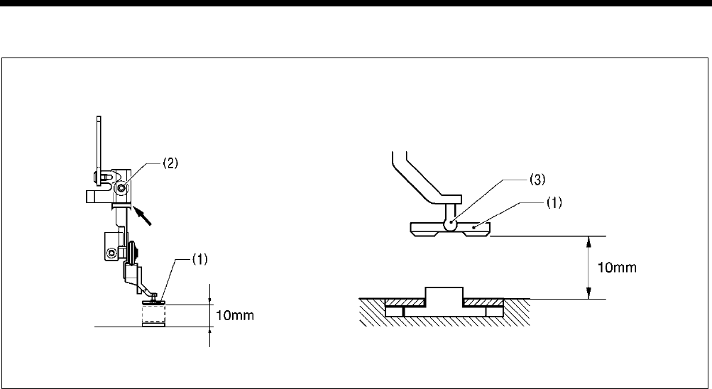
7. ADJUSTMENT
HE-800B
92
7-7. Adjusting the work clamp lift amount
1. Turn on the power and set the sewing machine to the home position.
2. Check that memory switch No. 002 (Work clamp height when treadle is at neutral) is 10 mm. (If it is not set to 10 mm, set it
to 10 mm.)
3. Place a 10 mm gauge under the work clamp (1) and then loosen the set screw (2) to make the adjustment.
* Adjust the lift amount (including the play in the work clamp (1) and the pin (3) to 10 mm. If it is set to more than 10 mm, the
work clamp will start lifting before lower thread trimming is complete, which may result in thread trimming errors.
Furthermore, it may also cause the presser foot lifter pulse motor to go out of step.
4298Q 4297Q
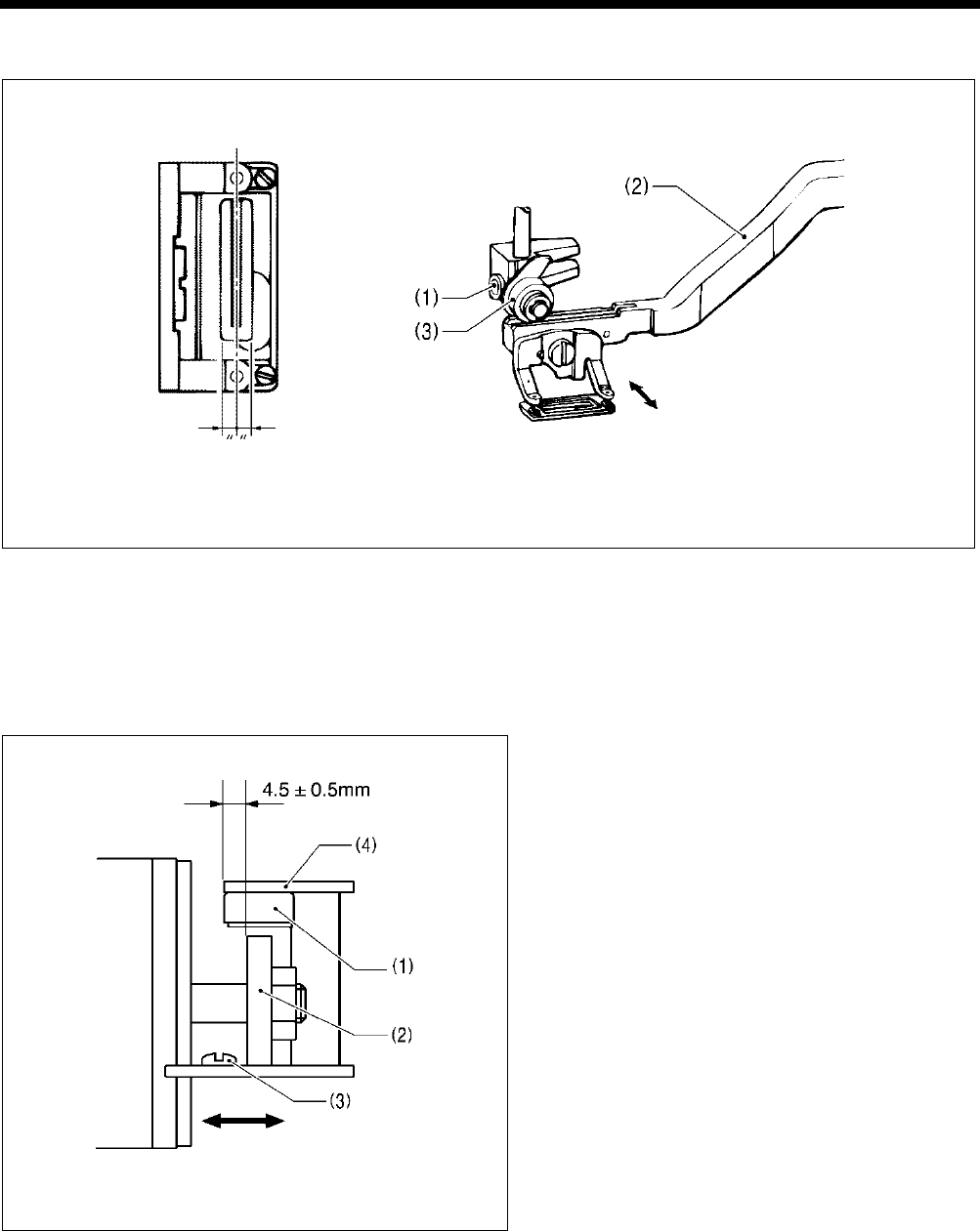
7. ADJUSTMENT
HE-800B
93
7-8. Adjusting the work clamp lateral position
1. Loosen the set screw (1), and then move the feed arm (2) and the roller (3) to adjust so that the knife groove comes to the
center of the work clamp window.
2. Operate the treadle and check that the work clamp moves up and down smoothly.
* After adjusting, check the upper thread trimmer mechanism and adjust if necessary.
7-9. Adjusting the cutter home position sensor position
Loosen the screw (3), and then adjust the cutter sensor
setting plate (4) so that there is a clearance of 4.5 ±
0.5 mm between the side of the cutter sensor (1) and the
edge of the solenoid stopper (2).
4300Q 4299Q
4301Q
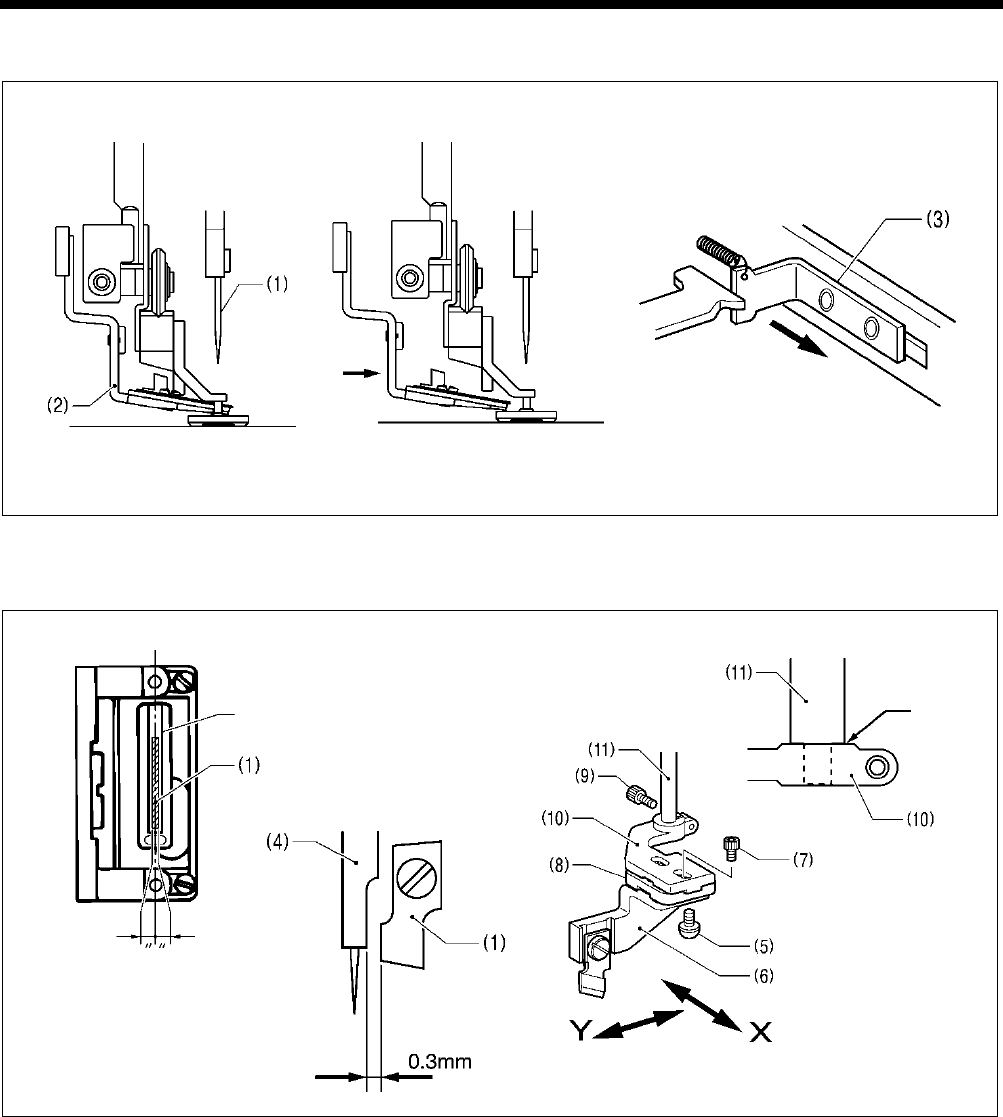
7. ADJUSTMENT
HE-800B
94
7-10. Adjusting the cutter installation position
Adjust so that the upper thread scissors (2) and the cutter (1) do not touch when the cutter (1) is pushed down by hand.
If the upper thread scissors (2) extends below the cutter (1), pull the stop plate (3) forward and move the upper thread scissors
(2) to the left. (Fig. A → Fig. B)
1. Loosen the screw (5), and adjust the cutter Y direction using cutter holder DL (6) so that the clearance between the needle
bar (4) and the cutter (1) is 0.3 mm.
Note: ・When replacing the cutter, be careful not to allow the cutter to touch the needle bar because of any play in the
cutter installation position.
・Check that the needle bar (4) does not touch the cutter when it moves sideways.
2. Loosen the two bolts (7) and adjust the cutter X direction using cutter holder M (8) so that the cutter (1) goes into the center
of the cutter groove.
3. Loosen the bolt (9) and move the cutter holder (10) to adjust the direction of rotation.
4. Check that the edge of the cutter holder (10) is touching the stepped section of the cutter driving shaft (11), and then tighten
the bolt (9).
5. After adjusting, push the upper thread scissors (2) back to its original position (Fig. A).
4303Q 0740D
Fig. A
Push Pulled forward
4306Q 4305Q
4304Q
Touching
Cutter groove
Fig. B
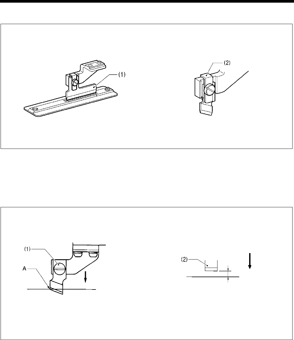
7. ADJUSTMENT
HE-800B
95
7-10-1. When using the special needle plate (needle plate -RB)
The special needle plate is used to prevent the cutter from getting stuck in the material and not returning.
1. The special needle plate has a narrow cutter groove of 0.3 - 0.4 mm, so use the accessory positioning plate (1) to adjust the
cutter installation position.
Note: If this adjustment is not made, the cutter may touch the needle plate, and damage to the cutter may result.
2. Install the cutter holder (2) to minimize any play in the cutter during cutting.
7-11. Adjusting the cutter installation height
Adjust so that the upper thread scissors and the cutter do not touch when the cutter is pushed down by hand. (Fig. A → Fig. B
in “7-10. Adjusting the cutter installation position”)
Install the cutter with the screw (1) so that the tip A of the cutter blade is aligned with the top of the needle plate when the cutter
is pressed down by hand to its lowest position.
If using the flat cutter (2), install with the screw (1) so that there is a clearance of 1.5 - 2.0 mm between the cutter and the top of
the needle plate.
* After adjusting, push the upper thread scissors back to its original position (Fig. A in “7-10. Adjusting the cutter installation
position”).
Note: ・When the cutter is driven by the solenoid, the movement will be approximately 2 mm greater than that shown in
the illustration.
・If the cutter does not cut properly, the cutter may get stuck in the material and not return. If this happens, replace or
sharpen the cutter.
4308Q 4307Q
0687D 4309Q
Lowest position
Top of needle plate
Lowest position
Top of needle plate
1.5 - 2.0 mm
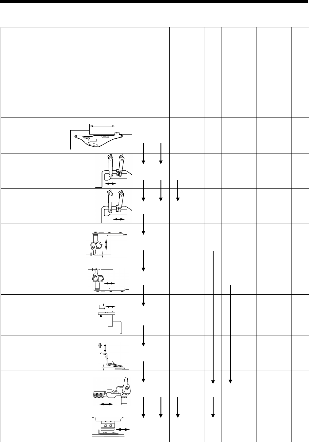
7. ADJUSTMENT
HE-800B
96
7-12
.
Adjusting the upper thread trimming
Upper thread trimming adjustment procedure
When adjusting for the first time
When the home position position has
been changed
When the longitudinal feed arm
position has been changed
When the trimmer driving arm position
has been changed
When the lateral position of the upper
thread scissors has been changed
When the longitudinal position of the upper
thread scissors has been changed
When the cutting depth of the upper thread
scissors has been changed
When the installation height of the upper
thread scissors has been changed
When the gradual opening timing of the upper
thread scissors has been changed
When the opening timing of the upper thread
scissors has been changed
7-2-4. Work clamp (P) motor home position
1 1
7-12-1. Adjusting the longitudinal feed arm
assembly position
2 2 1
7-12-2. Adjusting the trimmer driving arm
assembly position
3 3 2 1
7-12-3. Adjusting the lateral position of the upper thread
scissors at the sewing start
4 1
7-12-4. Adjusting the longitudinal position of the upper
thread scissors
5 1
7-12-5. Adjusting the cutting depth of the upper thread
scissors
6 1
7-12-6. Adjusting the installation height of the upper thread
scissors
7 1
7-12-7. Adjusting the upper thread scissors gradual
opening timing
8 4 3 2 2 1
7-12-8. Adjusting the upper thread scissors opening timing
9 5 4 3 1
4314Q
4315Q
4317Q
4319Q
1772B
1773B
0798D
1775B
0741D
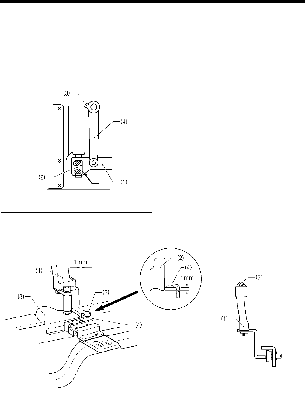
7. ADJUSTMENT
HE-800B
97
[CAUTION]
Before adjusting the upper thread trimming, check the home position of the work clamp (P) motor. (Refer to “7-2-4. Work
clamp (P) motor home position”.)
7-12-1. Adjusting the longitudinal feed arm assembly position
1. Turn on the power and set the sewing machine to the
home position. Then press the THREAD key to lower
the work clamp.
2. Check that the slot at the bottom of the upper thread
trimmer lever set (1) is aligned with the edge of the
washer (2).
3. If they are not aligned, loosen the bolt (3) and move
the longitudinal feed arm assembly (4) back and forth
to adjust.
7-12-2. Adjusting the trimmer driving arm assembly position
1. Turn on the power and set the sewing machine to the home position. Then press the THREAD key to lower the work clamp.
2. Check that the overlap between the stopper (2) fixed to the trimmer driving arm assembly (1) with the bolt and the stop plate
(4) of the upper thread trimmer lever set (3) is 1 mm.
3. If adjustment is necessary, loosen the bolt (5) and move the trimmer driving arm assembly (1) back and forward to adjust.
4320Q
1777B 1776B
Aligned
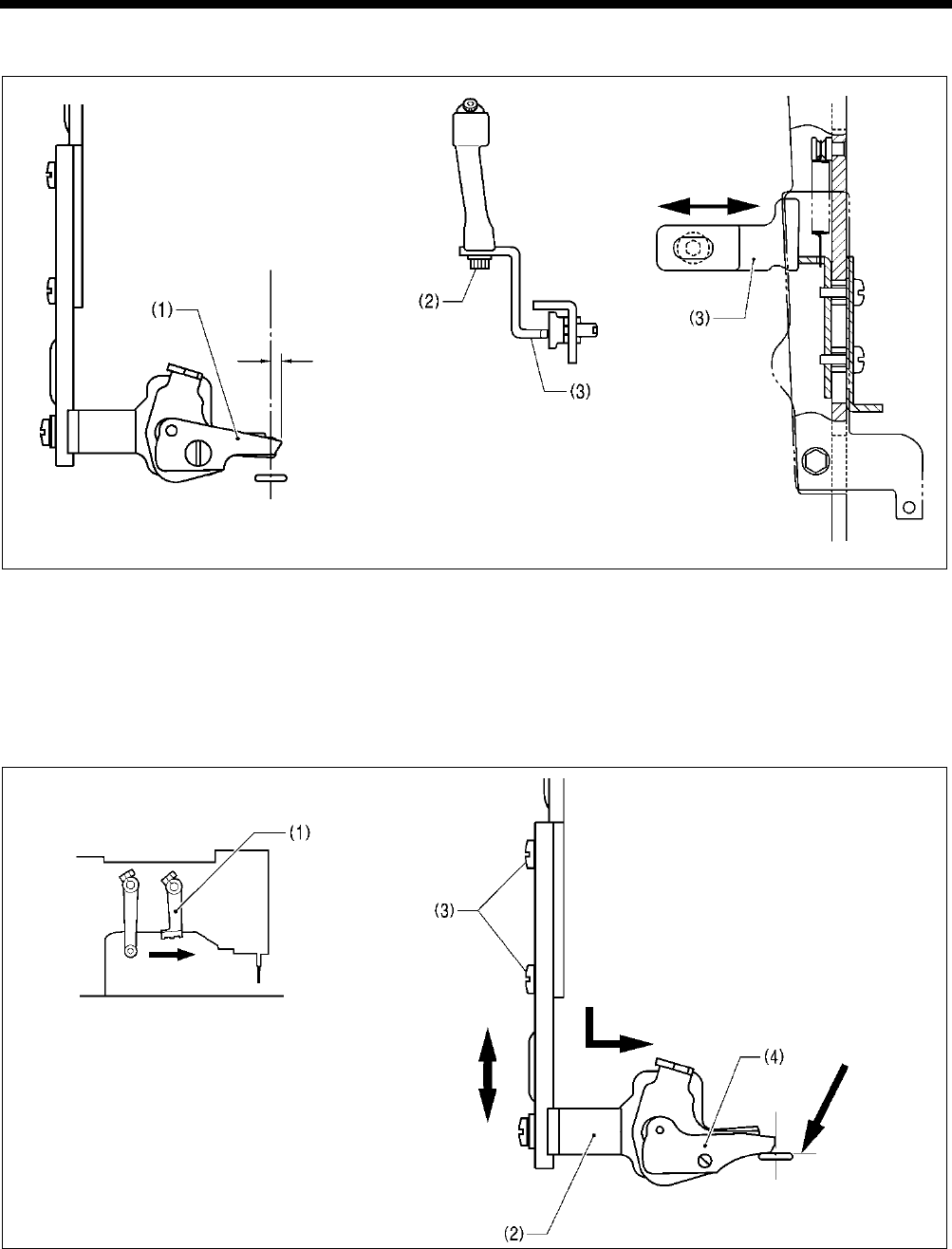
7. ADJUSTMENT
HE-800B
98
7-12-3. Adjusting the lateral position of the upper thread scissors at the sewing start
1. Turn on the power and set the sewing machine to the home position. Then press the THREAD key to lower the work clamp.
2. Loosen the bolt (2), and then move the stopper (3) in and out to adjust so that the edge of the upper thread scissors
assembly (1) protrudes by approximately 1 mm from the center of the cutter.
Note: If the amount of protrusion of the upper thread scissors assembly is too great, the scissors may touch the needle
when they open.
3. After adjusting, carry out “7-12-8. Adjusting the upper thread scissors opening timing”.
7-12-4. Adjusting the longitudinal position of the upper thread scissors
1. Turn off the power (with the feed mechanism at the home position), and then slowly move the trimmer driving arm (1)
forward until the upper thread scissors assembly (2) is at the position shown in the illustration.
2. Loosen the two screws (3), and then move the upper thread scissors assembly (2) back and forward to adjust so that the
front ridge line of upper thread scissors U (4) is aligned with the edge of the needle hole.
Note: If this adjustment is not carried out, it may result in thread trimming errors or needle breakages.
4323Q
4326Q
1779B
Approx. 1 mm
Aligned
1778B
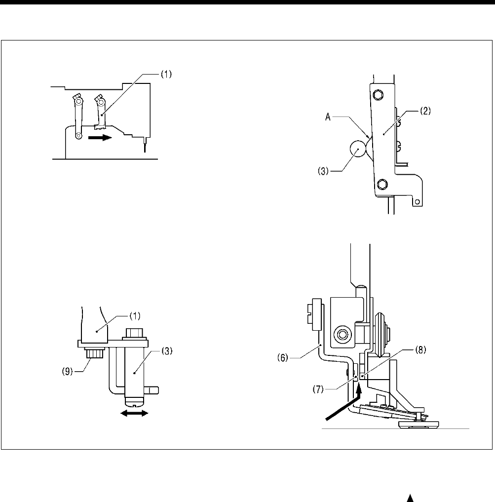
7. ADJUSTMENT
HE-800B
99
7-12-5. Adjusting the cutting depth of the upper thread scissors
1. Turn off the power (with the feed mechanism at the home position), and then slowly move the trimmer driving arm (1)
forward until the driving arm roller (3) is at its highest position on the cam A of the upper thread trimmer lever (2). (Upper
thread trimming position)
* Using the output check code function can help with making this adjustment. If you press the panel key while operating
at check code No. 53, the presser lifter pulse motor will operate one step at a time. Refer to “3-8. Output
checking method”.
2. Loosen the bolt (9), and then adjust the driving arm roller (3) so that the clearance between the stopper (7) of the upper
thread scissors assembly (6) and the opening cam bracket (8) is 0 - 0.3 mm.
Note: If the stopper (7) is adjusted so that it presses too firmly, it may cause the presser foot lifter pulse motor to go out of
step.
1780B 1779B
1781B 0720D
0 - 0.5 mm
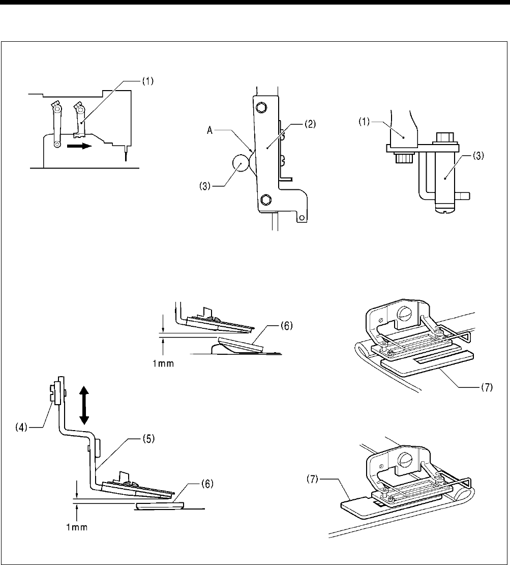
7. ADJUSTMENT
HE-800B
100
7-12-6. Adjusting the installation height of the upper thread scissors
1. Turn off the power (with the feed mechanism at the home position), and then slowly move the trimmer driving arm (1)
forward until the driving arm roller (3) is at its highest position on the cam A of the upper thread trimmer lever (2).
2. Loosen the screw (4), and then move the upper thread scissors (5) up or down to adjust the clearance between the upper
thread scissors (5) and the work clamp (6) to approximately 1 mm.
Note:
The work clamp (6) will tilt when sewing joints, so adjust so that the upper thread scissors (5) do not touch it. If the upper
thread scissors touch the work clamp, a work clamp lifter pulse motor error may occur.
* If the tilting of the work clamp (6) causes skipped stitches to occur when sewing material joints, use the accessory
auxiliary sheet (7) as shown in the illustration.
1782B 1779B
4333Q 4332Q
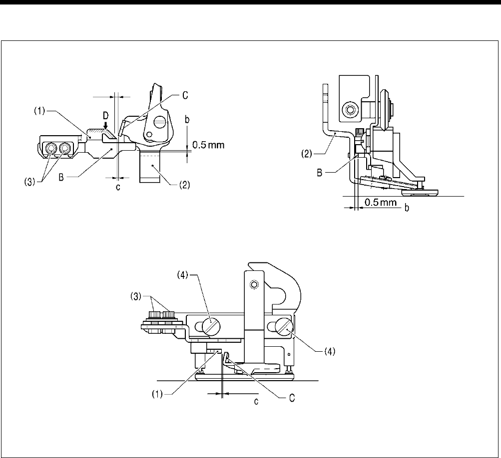
7. ADJUSTMENT
HE-800B
101
7-12-7. Adjusting the upper thread scissors gradual opening timing
1. Turn on the power and set the sewing machine to the home position. Then press the THREAD key to lower the work clamp.
2. Loosen the two bolts (3), and then adjust so that the distance b between ridge line B on the opening cam (1) and the upper
thread scissors (2) is 0.5 mm, and so that ridge line B on the opening cam is parallel to the feed direction.
3. Loosen the two screws (4), and then adjust so that the distance c between the rising section C of the upper thread scissors
(2) and the tip of the opening cam (1) is approximately 0.5 mm when the upper thread scissors (2) are closed.
* If you would like the scissors to start opening earlier, make the distance smaller. However, if you make the distance
smaller, check that the rising section C of the upper thread scissors (2) does not touch the opening cam (1) and prevent
the upper thread scissors (2) from opening when the work clamp is lowered.
4. Apply grease to the inclined face D of the opening cam (1).
5. Check that the upper thread scissors (2) gradually start opening after the material has been fed by 1.5 - 2.5 mm.
4106M
4105M
4104M
Approx. 0.5 mm
Start touching at 1.5 - 2.5 mm
Approx. 0.5 mm

7. ADJUSTMENT
HE-800B
102
7-12-8. Adjusting the upper thread scissors opening timing
1. Turn on the power and set the sewing machine to the home position. Then press the THREAD key to lower the work clamp.
2. Loosen the two bolts (3), and then adjust the support plate (4) so that the back plate (1) and the cam (2) overlap by
approximately 1.0 - 1.5 mm.
Note: If the amount of overlap is too small, the upper thread scissors will not open properly and the upper thread scissors
and the cutter may touch each other.
3. Loosen the two bolts (5), and then adjust the clearance between the bend in the back plate (1) and the cam (2) to
approximately 2 mm.
* If you would like the scissors to start opening earlier, make this clearance smaller.
4. Check the operation in test feed mode.
* Refer to the operating procedure given in “5-9. Upper thread trimmer mechanism”.
1787B 1786B
Feed arm
1788B
Approx. 2 mm
Approx. 1.0 - 1.5 mm
Approx. 2 mm
Approx.
1.0 - 1.5 mm
Approx. 1.0 - 1.5 mm
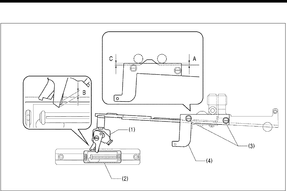
7. ADJUSTMENT
HE-800B
103
7-12-9.
Adjusting the overlapping amount of the upper thread scissors and the work
clamp
1. Turn on the power, move the feed mechanism to the home position, and then press the THREAD key to lower the work
clamp and move the roller of the trimmer driving arm to the home position.
2. With the power turned off, move the feed arm forward by hand until the upper thread scissors begin to open, and then return
the feed arm to its position before it was moved.
3. Loosen the two screws (3) and move the adjusting plate (4) to set the distance A in the illustration so that the overlapping
amount B between the tip of the scissors D assembly (1) and the work clamp (2) is 1.0 mm to 1.5 mm. Then tighten the two
screws (3).
4. Next, with the power turned off, mote the trimmer driving arm forward by hand as far as it will go.
5. Once again loosen the two screws (3) and move the adjusting plate (4) to set the distance C in the illustration so that the
overlapping amount B between the tip of the scissors D assembly (1) and the work clamp (2) is 1.0 mm to 1.5 mm. Then
tighten the two screws (3).
* Make sure that the position (distance A) which was set in steps 1 and 2 does not change at this time.
6. Turn on the power, depress the treadle to move the feed mechanism to the home position, and then switch to test mode and
check that the scissors D assembly (1) is always overlapping the work clamp (2).
0751D
Roller position
at step 2
Roller position
at step 4
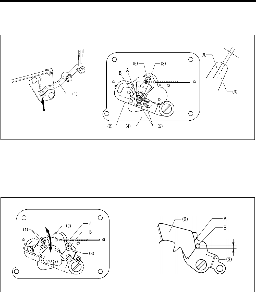
7. ADJUSTMENT
HE-800B
104
7-13. Adjusting the lower thread trimming
7-13-1. Adjusting the lower thread trimmer fixed knife engagement amount
1. With the power turned off, move the lower thread trimmer cam lever (1) in the direction of the arrow so that the knife driving
lever (2) is in the position shown in the illustration.
2. Check that the cam A of the movable knife (3) is sitting securely on top of the cam B of the base plate (4).
3. Loosen the two screws (5), and then adjust so that the fixed knife (6) and the movable knife (3) are engaged by
approximately 1 mm.
* If the engagement amount is too small, the lower thread may not be fully cut, and the material may get caught when it is
removed after sewing.
7-13-2
.
Adjusting the lower thread retaining amount
1. Turn on the power and set the sewing machine to the home position.
2. Loosen the two screws (1), and then adjust the lower thread retainer (2) to a distance of 1 - 2 mm as shown in the
illustration.
* If the lower thread retaining amount has been reduced, check that the roller B of the lower thread clamp plate (3) is sitting
securely on top of the lower thread retainer cam A.
* If the lower thread is pulling up at the first stitch at the sewing start, check if the lower thread is not being pulled out of the
lower thread clamp plate (3), and that it is not too loose when it is coming out from the bobbin case.
If the lower thread retaining amount is too small
The lower thread will pull out of the lower thread clamp plate at the first stitch at the sewing start, which can cause problems
such as lower thread cast-off, lower thread loops or poor lower thread winding.
If the lower thread retaining amount is too great
This can cause problems such as poor sealing at the sewing start, or wound lower thread sticking out of the rear tack.
4343Q 4342Q
4345Q 4344Q
Approx.
1 mm
Lower thread trimming complete
Smaller
Larger
1
– 2 mm
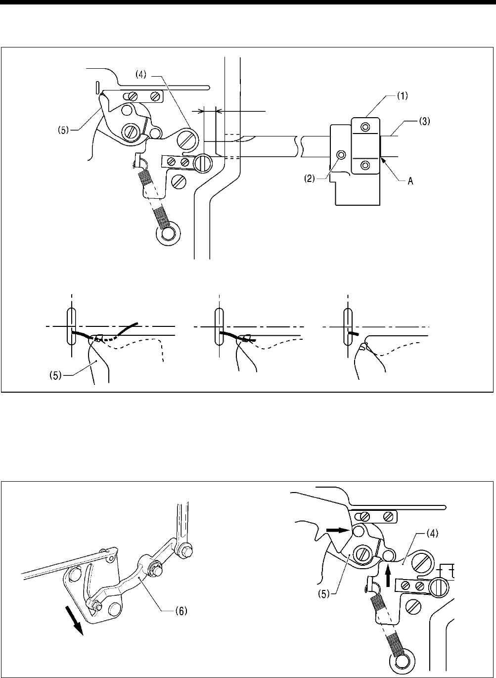
7. ADJUSTMENT
HE-800B
105
7-13-3. Adjusting the lower thread clamp opening timing
1. Loosen the set screw (2) of the feed arm support (1), and then align reference line A of feed guide shaft B (3) with the edge
of the feed arm support (1).
2. When the feed mechanism moves by 6 - 7 mm, the opening plate (4) moves and the lower thread clamp (5) opens.
3. To change the opening timing, loosen the set screw (2) and move the feed guide shaft B (3) to the left or right to adjust.
* The end of the thread which is being held by the lower thread clamp (5) is wound around inside the seam. If the opening
timing is too early, it can cause problems such as poor winding or pulling-up of the lower thread. If the opening timing is
too late, it can cause problems such as stretching, uneven seams or bird’s nests at the sewing start, depending on the
type of material.
Note: After moving the lower thread trimmer cam lever (6) back in the direction of the arrow, move the feed mechanism.
If the feed mechanism is moved when the lower thread trimming has been carried out, the mechanisms will press
against each other, which may result in damage to the lower thread clamp (5) and the opening plate (4).
4349Q 4348Q
4347Q
0752D
Approx.
6 – 7 mm
Sewing start
Lower thread winds around seam
Lower thread releases from
lower thread clamp
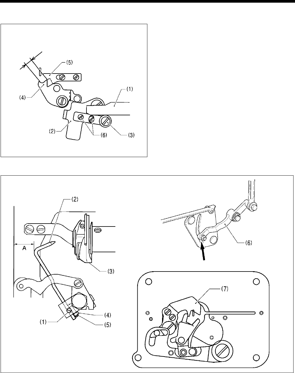
7. ADJUSTMENT
HE-800B
106
7-13-4. Adjusting the lower thread clamp opening amount
Loosen the two screws (6), and then adjust so that the
distance between the lower thread clamp (4) and the
lower thread presser (5) is approximately 5 mm when the
feed guide shaft (1) is projecting out at the front and is
firmly touching the roller (3) of opening plate (2).
7-14. Adjusting the bobbin presser
1. Turn on the power and set the sewing machine to the home position. Then press the THREAD key to lower the work clamp.
2. Loosen the set screw (1), and then adjust so that the bobbin presser (2) goes into the hole in the bobbin case (3).
3. Check that the work clamp is at the home position, and then loosen the nut (4) and turn the screw (5) to adjust the clearance
A between the bobbin presser (2) and the edge of the bed to approximately 12.5 mm.
4. Turn off the power, move the lower thread trimmer cam lever (6) by hand in the direction of the arrow to check that the
bobbin presser (2) presses the bobbin firmly before the lower thread retainer (7) starts to hold the lower thread.
Note: If this timing is reversed, it will cause problems such as an excess trailing length of upper thread.
4351Q
4352Q
4350Q
3989Q
Approx.
5 mm
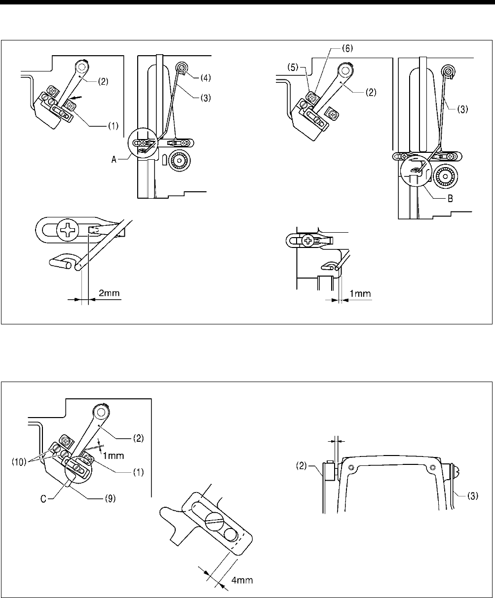
7. ADJUSTMENT
HE-800B
107
7-15. Adjusting the thread breakage detector
1. Tighten the lever stopper (1) inside the slotted hole.
2. Loosen the screw (4), and then adjust so that the distance A at the thread guide (3) is 2 mm when the thread breakage
detector lever (2) contacts the lever stopper (1).
3. Loosen the screw (6) of the lever stopper (5), and then adjust so that the distance B at the thread guide (3) is 1 mm when
the thread breakage detection lever (2) contacts the stopper (5).
4. Loosen the screw (7), and then adjust so that the distance C at the balancer (8) is 4 mm.
5. Turn on the power and set the sewing machine to the home position. Then press the THREAD key to lower the work clamp.
6. Loosen the two screws (10), and then adjust so that the thread breakage detector sensor (9) turns on (LED illuminates)
when the distance between the thread breakage detection lever (2) and the lever stopper (1) is 1 mm.
7. When the thread guide (3) is moved to position B and then released, check that it moves smoothly back to position A.
8. If the thread guide (3) does not move smoothly, check that the clearance between the thread breakage detection lever (2)
and the arm is 0.1 - 0.5 mm.
4354Q 4353Q
4355Q 0743D
0.1 - 0.5 mm
Section A
Touching
Section B
Section C
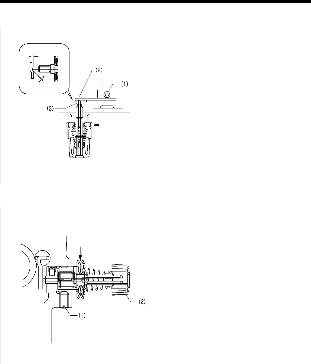
7. ADJUSTMENT
HE-800B
108
7-16. Adjusting the thread tension at the tack tension control
1. Turn on the power and set the sewing machine to the
home position. Then press the THREAD key to lower
the work clamp.
2. Loosen the set screw (1), and then adjust the
clearances between the tension release cam (2) and
the tension release pin (3) as shown in the illustration.
3. Press the THREAD key and check that the tension disc
opening amount is 0.5 - 1.0 mm when the work clamp
is raised.
4. Press the THREAD key once more and check that the
tension discs are fully closed when the work clamp is
lowered.
7-17. Adjusting the thread tension at the zigzag tension control
Position the tension release solenoid as described in "6-4.
Tension release mechanism (1)" before carrying out this
adjustment.
1. Turn on the power and set the sewing machine to the
home position. Then press the THREAD key to lower
the work clamp.
2. Loosen the set screw (1), and then move the tension
stud bracket assembly (2) in and out to adjust so that
the tension disc opening amount is 0.5 - 1.0 mm.
3. Check that the tension discs are fully closed when the
power is turned off.
0744D
0745D
0.3 - 0.5 mm
0.1 - 0.3 mm
0.5 - 1.0 mm
0.5 - 1.0 mm
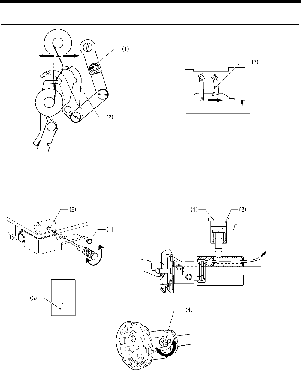
7. ADJUSTMENT
HE-800B
109
7-18. Adjusting the upper thread feeding amount
1. Loosen the screw (1), and then turn the tension take-up lever (2) to adjust the upper thread feeding amount.
2. Move the trimmer driving arm (3) by hand and check that upper thread feeding is completed before the upper thread is cut.
Note: If the above adjustment is not made, it may result in the upper thread pulling out or in upper thread clamping errors.
7-19. Adjusting the rotary hook lubrication
1. Remove the rubber cap (1).
2. Turn the adjusting screw (2) to adjust the lubrication amount.
* Adjust so that approximately 10 drops of oil are released when the sewing machine is run at a speed of 4,000 rpm for
three cycles to sew about 114 stitches. Use Kraft paper (3) or similar to catch the oil drops. As a guide, the optimum
position can be obtained if the adjusting screw (2) is tightened as much as possible and then loosened about two turns.
* Furthermore fine adjustments can then be made using the rotary hook joint screw (4).
* If the lubrication amount has been reduced, run the machine for 200 - 300 sewing cycles and then check it again.
Note: If lubrication stops, it will cause problems such as rotary hook seizure and thread breakages.
1792B 0753D
4365Q
4364Q
4366Q
Increase
Decrease
To oil tank
More
Less
More
Less
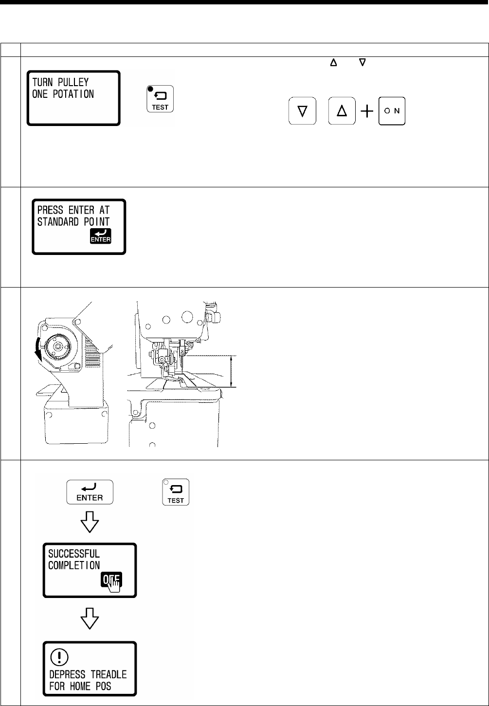
7. ADJUSTMENT
HE-800B
110
7-20. Adjusting the upper shaft motor reference position
1
Turn off the power and then remove the needle.
2
While pressing the and key simultaneously, turn on the
power switch.
• The TEST indicator will flash and the upper shaft rotation
standby screen will be displayed.
3
Turn the pulley one full turn in the direction of the arrow.
•
“PRESS ENTER AT STANDARD POINT” will be
displayed.
* If nothing is displayed, turn the pulley by hand until the
display appears.
4
Turn the pulley in the direction of the arrow to move the
needle bar until the distance A from the top of the needle
plate to the bottom edge of the needle bar is as given below.
-2 specifications: 43.2 mm
-3 specifications: 42.4 mm
5
End adjustment mode.
To confirm the reference position, press the ENTER key.
•
“SUCCESSFUL COMPLETION” will be displayed for
1.5 seconds, and then the display will return to the
normal display and the sewing machine will change to
home position standby.
To exit without confirming the reference position, press the
TEST key.
• The display will return to the normal display and the
sewing machine will change to home position standby.
0821D
0763D
0822D
0754D
A
0823D
Flashing
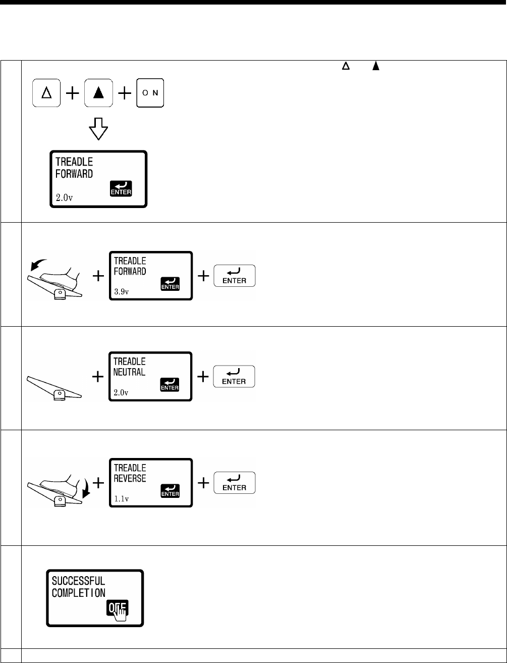
7. ADJUSTMENT
HE-800B
111
7-21. Standard settings for treadle depression stroke
The following procedure sets the operating positions for the treadle depression strokes to the standard values.
1
Enter the signal settings.
While pressing the and keys, turn on the power switch.
2
Store the maximum forward depression amount.
With the treadle depressed all the way forward, wait until the
voltage display value stabilizes and then press the ENTER
key.
3
Store the neutral position.
With your foot released from the treadle, wait until the voltage
display value stabilizes and then press the ENTER key.
4
Store the maximum backward depression amount.
With the treadle depressed all the way backward, wait until
the voltage display
value stabilizes and then press the
ENTER key.
5
End the settings.
“SUCCESSFUL COMPLETION” will be displayed on the
screen.
NOTE:
If the operation of the treadle is incorrect, a buzzer will
sound.
Repeat the operation from step 2.
6
Turn off the power switch.
0739D
0824D
0825D
0826D
0827D
0828D
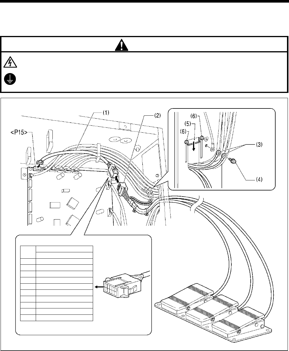
8. INSTALLING THE 3-PEDAL FOOT SWITCH (OPTION)
112
HE-800B
8. INSTALLING THE 3-PEDAL FOOT SWITCH (OPTION)
The foot switch conversion harness (SB1565001) that is sold separately is required.
DANGER
Wait at least 5 minutes after turning off the power switch and disconnecting the power cord from the wall outlet before
opening the face plate of the control box. Touching areas where high voltages are present
will result in serious injury
from electric shocks
.
Be sure to connect the ground.
If the ground connection
is not secure, you run a high risk of serious injury from electric shocks, and problems with
correct
operation will also occur.
1. Insert the foot switch conversion harness (1) into connector <P15> on the main PCB.
2. Connect the connector (2) for the 3-pedal foot switch to the foot switch conversion harness (1).
3. Temporarily remove the screw (4) from the ground terminal of the control box, and then connect the two ground wires (3) in
the 3-pedal foot switch harness to the ground terminal and retighten the screw to the ground terminal.
4. Close the cord presser plate (5) in the direction of the arrow, and secure it by tightening the two screws (6).
NOTE:
・ Make sure that the ground connections are secure in order to ensure safety.
・ Close the cord presser plate (5) securely so that no foreign objects, insects or small animals can get inside the control
box.
No.
3-pedal foot switch
10P connector
1
-
2
-
3
-
4
-
5
Start
6
0V
7
0V
8
Clamp
9
Option
10
0V
0764D

9. ELECTRIC MECHANISM
HE-800B
113
9. ELECTRIC MECHANISM
DANGER
Wait at least 5 minutes after turning off the power switch and disconnecting the power cord from the wall outlet
before opening the face plate of the control box. Touching areas where high voltages are present will result in
serious injury from electric shocks.
9-1. Precautions at the time of adjustment
Electric shock
Some large capacitors may have a high voltage remaining in them for up to 5 minutes after the power is turned off. To prevent
electric shock, wait at least 5 minutes after the power is turned off before doing the following:
• Opening and closing the control box
• Replacing fuses
• Separating and joining connectors
• Measuring resistance
• Doing anything with a possibility of touching something inside the control box
Some adjustments require measuring the voltage while the power is turned on with the control box kept open.
In such a case, be careful not to touch any place other than that for the measurement. In addition, always keep in mind that a
high voltage remains for about 5 minutes after power is turned off.
Injury
When separating or rejoining connectors, and measuring something, be careful not to cut your fingers on metal parts such as
heat sinks and covers.
Pay attention to the following when opening the control box for maintenance.
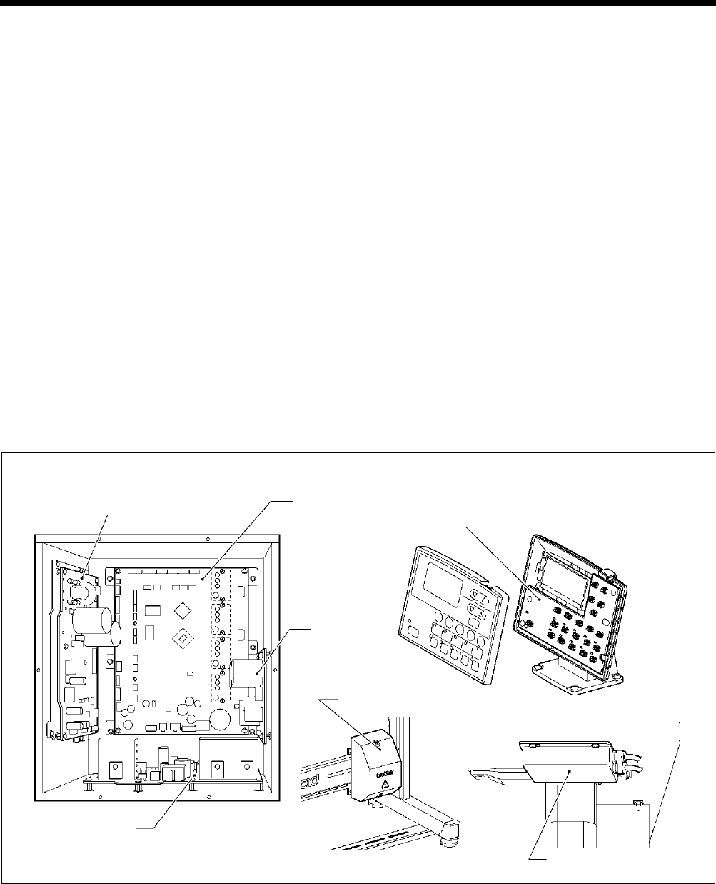
9. ELECTRIC MECHANISM
HE-800B
114
9-2. Components inside and outside the control box and in the operation panel
Main PCB
Secured to the rear. This PCB drives the pulse motor and solenoids.
Motor PCB
Secured to the side. This PCB drives the main shaft motor. There are two fuses on this PCB.
Power PCB
Secured to the base. This PCB generates the voltages which are required for control operations.
Cutter PCB
Secured to the side. This PCB drives the solenoid.
Conversion transformer box (100V, 110V, 380V, 400V AC specifications only)
Steps-down the power supply voltage and generates the voltages that are required for the control box.
NF box (For Europe)
Eliminates electrical noise that is transmitted along the power supply line.
Panel PCB
Secured inside the operation panel. This PCB controls indications of the machine status and the input operation.
Control box
0765D
Operation panel
Panel PCB
Transformer box
NF box
Power PCB
Main PCB
Motor PCB
Cutter PCB
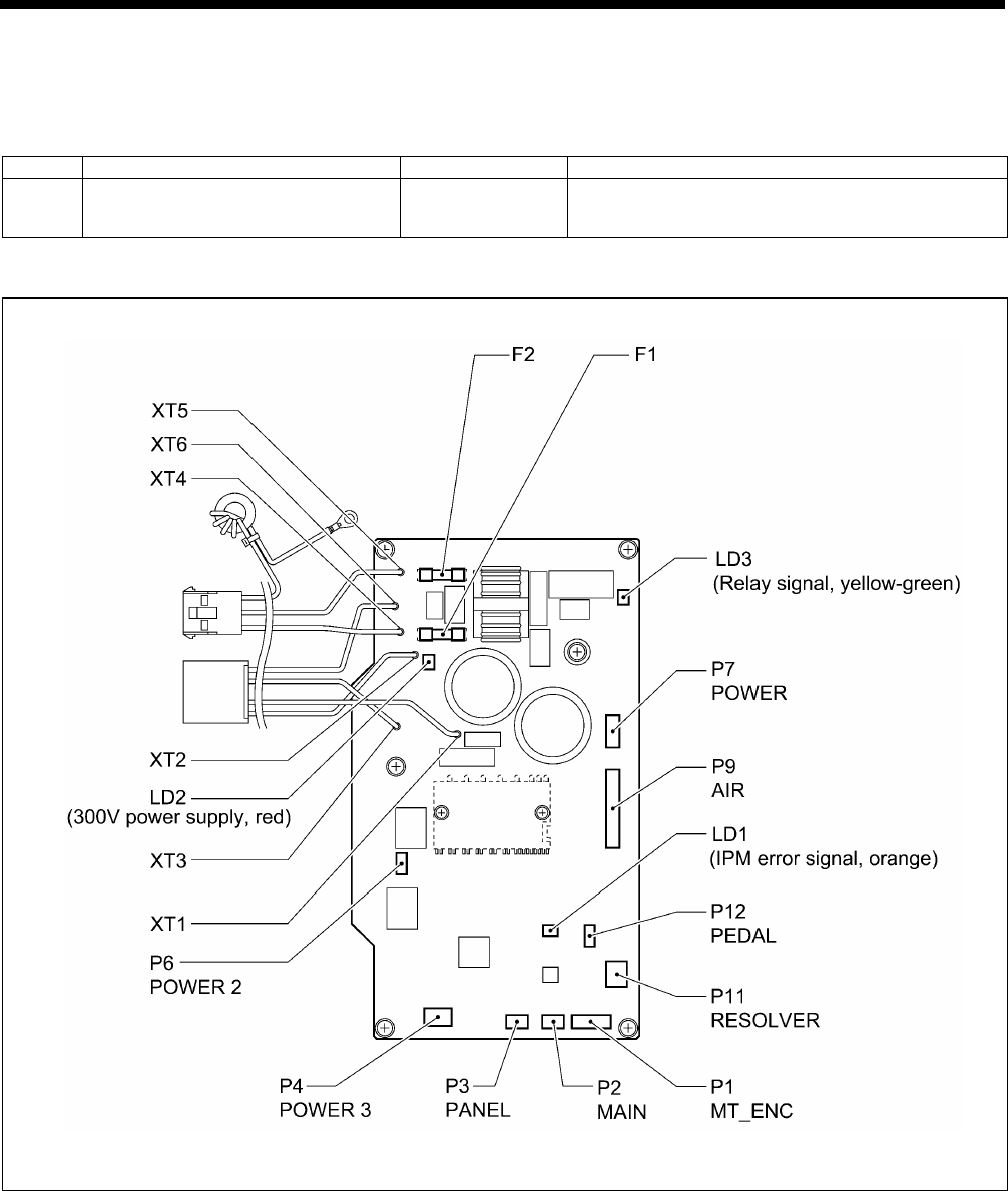
9. ELECTRIC MECHANISM
HE-800B
115
9-3. Fuse explanation
When replacing a fuse, be sure to use the specified ones listed below.
If a component on a PCB is damaged, the fuses may blow again soon even after they have been replaced.
No.
Part name
Part code
When a fuse has blown
F1
F2
G Fuse 10A-250V
(glass tube fuse, 10A-250V) J04417-001 The power indicator is not illuminated, and
nothing operates.
Motor PCB
2930B
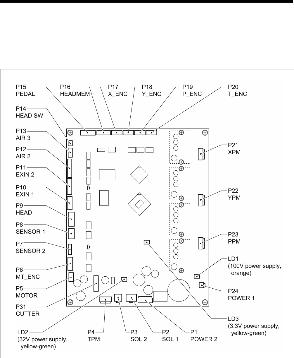
9. ELECTRIC MECHANISM
HE-800B
116
9-4. Connectors
Most of the machine trouble is due to connector problems including improper connection or sufficient contact. Therefore, be
sure to check if each connector is correctly inserted and that there is no contact failure between pins and wires before starting
troubleshooting procedures.
9-4-1. Connector positions
Main PCB
Motor PCB
(Refer to the diagram in “9-3. Fuse explanation”.)
0830D
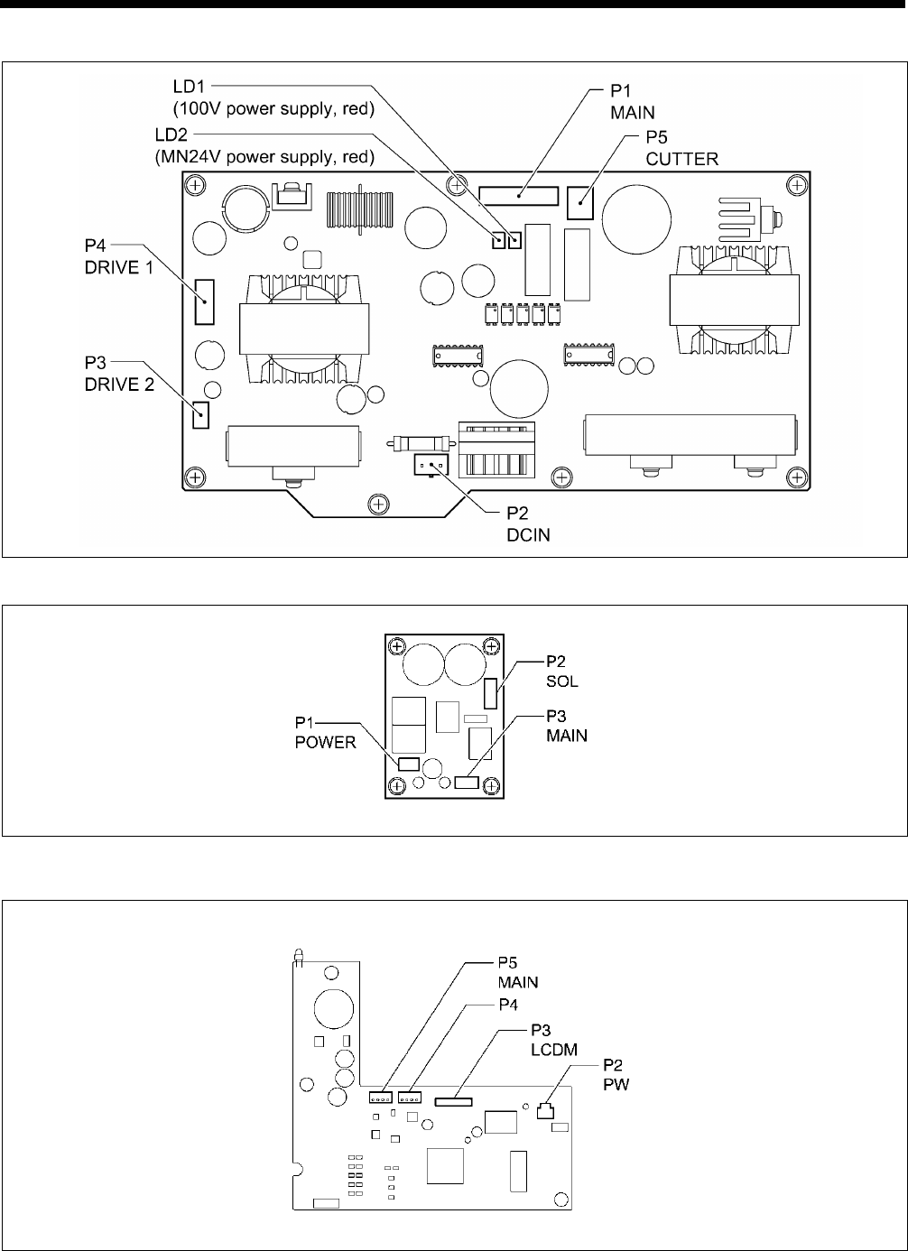
9. ELECTRIC MECHANISM
HE-800B
117
Power PCB
Cutter PCB
LCD panel PCB
0831D
0768D
0769D
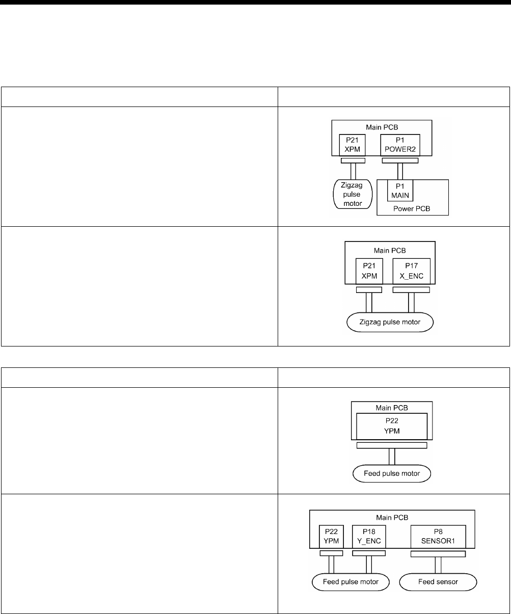
9. ELECTRIC MECHANISM
HE-800B
118
9-4-2. Contact failure
The connectors functions are divided into five categories. Some connectors may belong to more than one group. Be sure to
investigate another category if a problem is not found in one category.
Zigzag mechanism
Problem Connector No. and position
• The needle bar does not move sideways during home position
detection immediately after the power is turned on.
• [E200] is displayed.
• The needle bar moves sideways but does not detect the home
position correctly.
• Problem with zigzag operation.
• [E200] or [E201] is displayed.
Feed mechanism
Problem Connector No. and position
• The feed motor does not operate for home position detection
immediately after the power is turned on.
• Error E210 is displayed.
• The feed mechanism moves back and forth but does not detect
the home position correctly.
• Problem with feed plate operation.
• [E210] or [E211] is displayed.
0832D
0833D
0834D
0835D
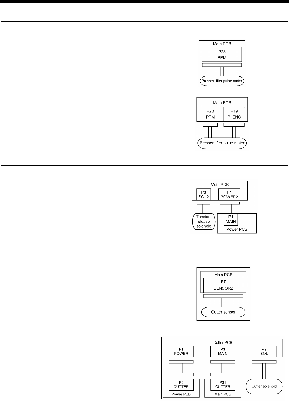
9. ELECTRIC MECHANISM
HE-800B
119
Work clamp mechanism
Problem Connector No. and position
• Work clamp does not move during home position detection
immediately after the power is turned on.
• [E300] is displayed.
• The work clamp moves up and down but does not detect the
home position correctly.
• Problem with work clamp operation.
• [E300] or [E301] is displayed.
Tension release mechanism
Problem Connector No. and position
• Tension release does not operate (no error displayed).
Cutter mechanism
Problem Connector No. and position
• Error E650 is displayed when the power is turned on.
• Cutter does not operate.
• [E651] is displayed.
0838D
0839D
0840D
0836D
0837D
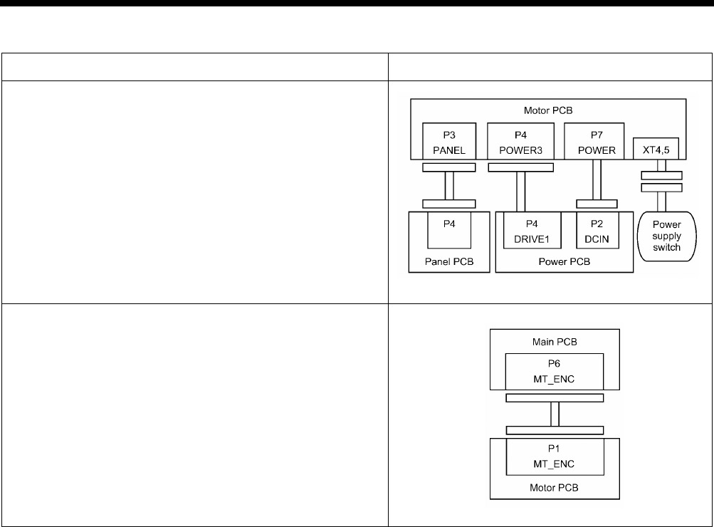
9. ELECTRIC MECHANISM
HE-800B
120
Sewing operation
Problem Connector No. and position
• The power indicator is not illuminated, and nothing operates.
• Machine operation is unstable.
• [E130] or [E131] is displayed.
• The main shaft motor does not operate correctly.
• Error E130 is displayed.
0841D
0842D
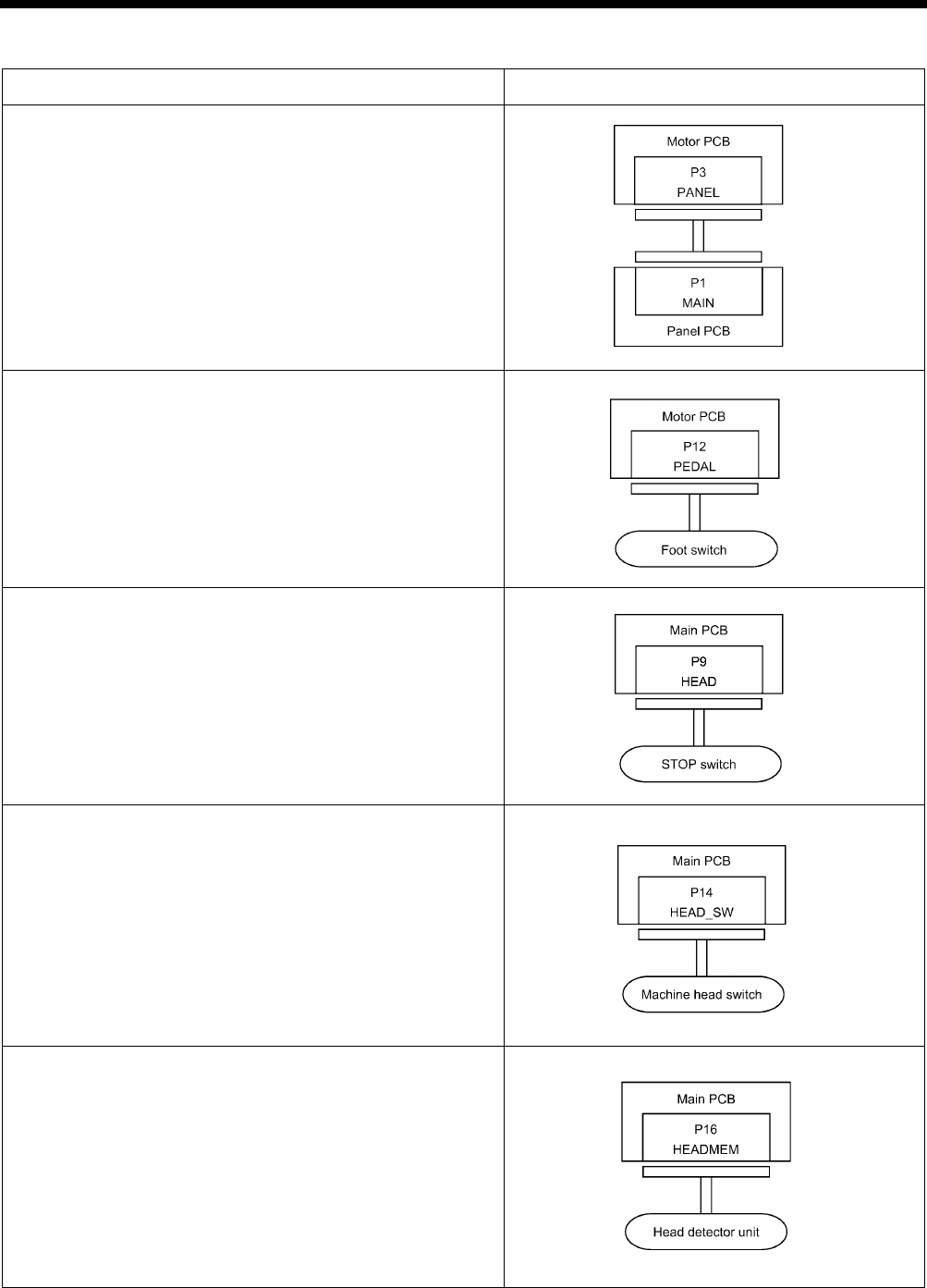
9. ELECTRIC MECHANISM
HE-800B
121
Others
Problem Connector No. and position
• Panel indication is strange.
• The power indicator is not illuminated.
• Any operation panel key does not have any effect.
• The sewing machine does not operate when the foot switch is
depressed. (No error display.)
• After the power is turned on, [E015] or [E016] is displayed.
• Error E055 is displayed after the power is turned on.
• Error E452 is displayed after the power is turned on.
(Continued on next page.)
0843D
0844D
0845D
2944B
2945B
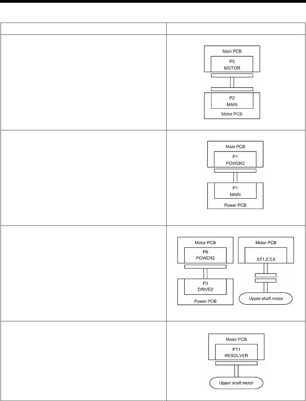
9. ELECTRIC MECHANISM
HE-800B
122
Others
Problem Connector No. and position
• The WELCOME display does not disappear and the sewing
machine does not start.
• Only the power indicator illuminates.
• Nothing appears on the operation panel display.
• The sewing machine does not operate when the foot switch is
depressed.
• Error E130 is displayed.
• Error E131 is displayed.
0848D
0849D
2948B
2949B
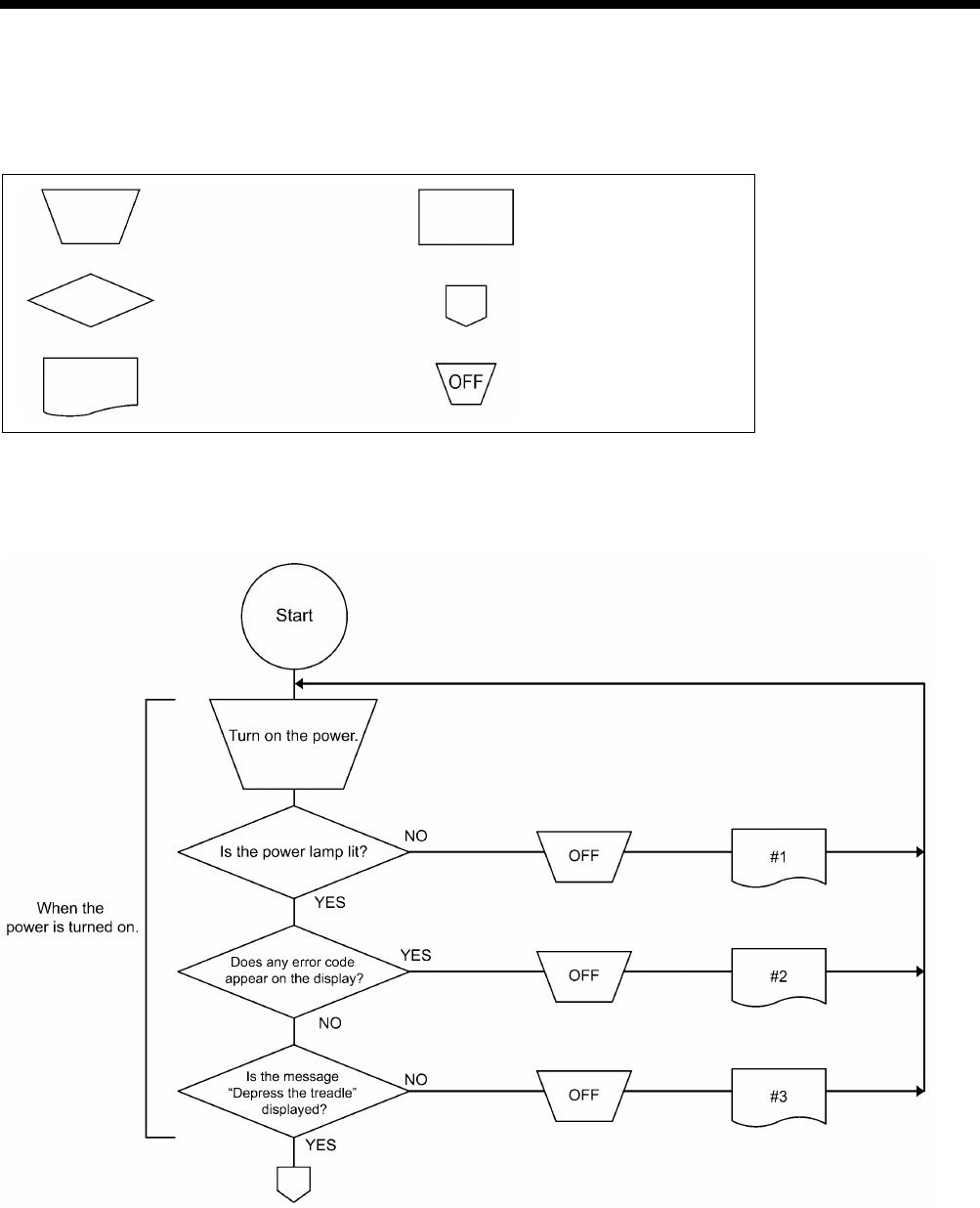
9. ELECTRIC MECHANISM
HE-800B
123
9-5. Troubleshooting
9-5-1. Troubleshooting flowchart
Symbols and their meanings
Switch operation Set-up operation or
condition
Yes-or-no
decision-making process
The procedure to
follow continues on the
next page
The error status number
in the first column of the
table of “9-5-2. Problem
solution and measures”
Turning-
off of the
power switch
2707B
0850D
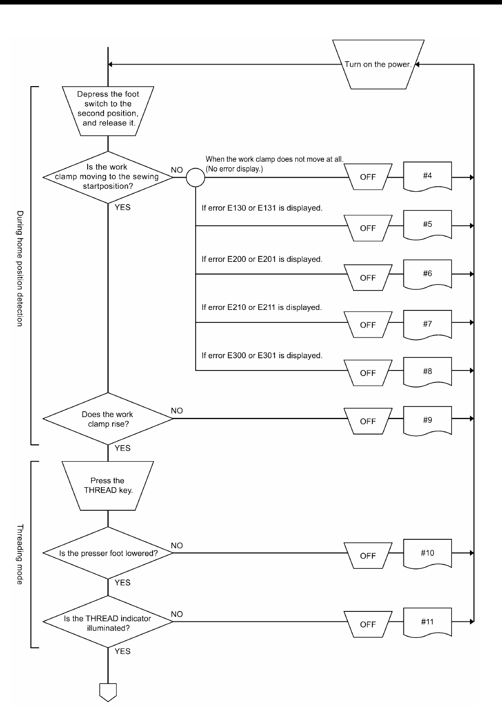
9. ELECTRIC MECHANISM
HE-800B
124
0851D
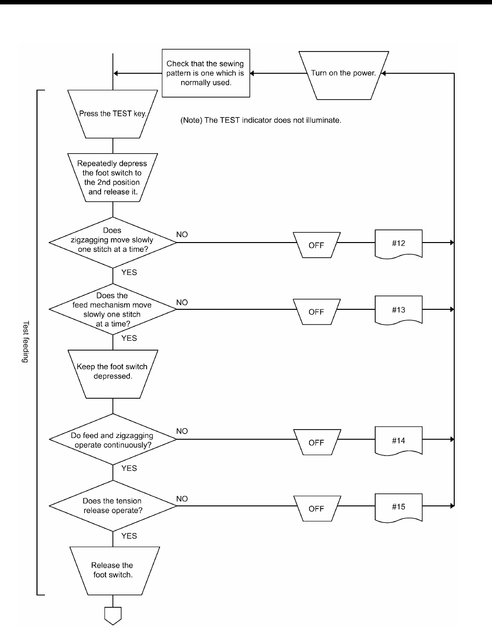
9. ELECTRIC MECHANISM
HE-800B
125
0852D
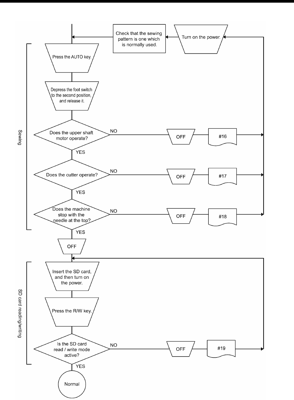
9. ELECTRIC MECHANISM
HE-800B
126
0853D

9. ELECTRIC MECHANISM
HE-800B
127
9-5-2. Problem solution and measures
DANGER
Wait at least 5 minutes after turning off the power switch and disconnecting the power cord from the wall outlet
before opening the face plate of the control box. Touching areas where high voltages are present will result in
serious injury from electric shocks.
1. Pay attention to the following when opening the control box for maintenance.
Electrical shock
Some large capacitors may have a high voltage remaining in them for up to 5 minutes after the power is turned off.
To prevent electrical shock, wait at least 5 minutes after the power is turned off before doing the following:
• Opening and closing the control box
• Replacing fuses
• Separating and joining connectors
• Measuring resistance
• Doing anything with a possibility of touching something inside the control box
Injury
When separating or rejoining connectors, and measuring something, be careful not to cut your fingers on metal parts such
as heat sinks and covers.
2. When replacing a fuse, be sure to use a new one of the same quality and capacity as the old one.
Before adjustment
1. While the power is turned off, check each connector is securely plugged in by referring to “9-4. Connectors”.
2. Find the error status number in the troubleshooting flowchart.
3. From the applicable part of the flowchart, take the reference number to find the correspondingly numbered details of the
problem in the following table.
Some adjustments require measuring the voltage while the power is turned on with the control box kept open.
In such a case, be careful not to touch any place other than that for the measurement. In addition, always keep in
mind that a high voltage remains for about 5 minutes after power is turned off.
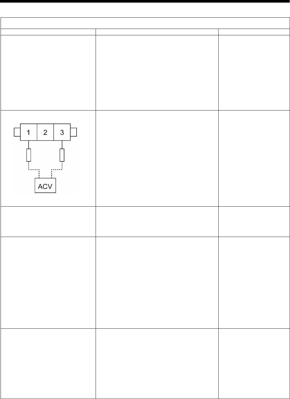
9. ELECTRIC MECHANISM
HE-800B
128
Error status #1 The power indicator does not light when the power is turned on.
Probable causes
Check/ repair/ adjust
Parts to be replaced
1. (Check the LEDs)
Turn on the power switch and check that the
various LEDs illuminate in the following order.
a. LD2 (red) on motor PCB does not illuminate.
→#1-2、#1-3、#1-4
b. LD2 (red) on power PCB does not illuminate.
→#1-5、#1-6、#1-7、#1-8
c. LD3 (green) on motor PCB does not
illuminate.
→#1-9
d. Power indicator on panel does not illuminate.
→#1-10
2. Malfunction of power cord
Turn off the power switch, disconnect the power
supply connector which links the power cord for
the power switch and the motor PCB, turn on the
power switch, and then measure the AC voltage
between terminals 1 and 3 of the cord-side
connector.
OK if the voltage is the same as mains voltage.
In addition, check that the power supply voltage at
the wall outlet is within the range of the
specification voltage +/- 10%.
After inspecting, turn off the power switch and
connect the power supply connector.
3. Blown fuse
Turn off the power switch, wait 5 minutes or more,
and then remove fuses F1 and F2 on the motor
PCB and check their continuity.
OK if continuity
GFUSE10A-250V
(10A-250V)
4. Malfunction of motor PCB 1
Turn off the power switch, disconnect P2 (DCIN)
from the power PCB, and then turn on the power
switch and check LD2 (red) on the motor PCB.
OK if illuminated.
After checking, turn off the power switch, wait for
five minutes or more, and then insert P2 into the
power PCB.
Turn the power switch back on, and then with P2
inserted into the power PCB, check the voltage
between terminals 1 and 3 of P2.
OK if 240 to 380 V DC.
Motor PCB assembly 800B
5. Malfunction of power PCB
Turn off the power switch, disconnect connector
P1 (POWER2) from the main PCB and
connectors P4 (POWER3) and P6 (POWER2)
from the motor PCB, and then turn on the power
switch and check LD2 (red) on the power PCB.
OK if illuminated.
After checking, turn off the power switch, wait for
one minute or more, and then insert P1 into the
main PCB and P4 and P6 into the motor PCB.
Power PCB assembly
(Continued on next page.)
2712B
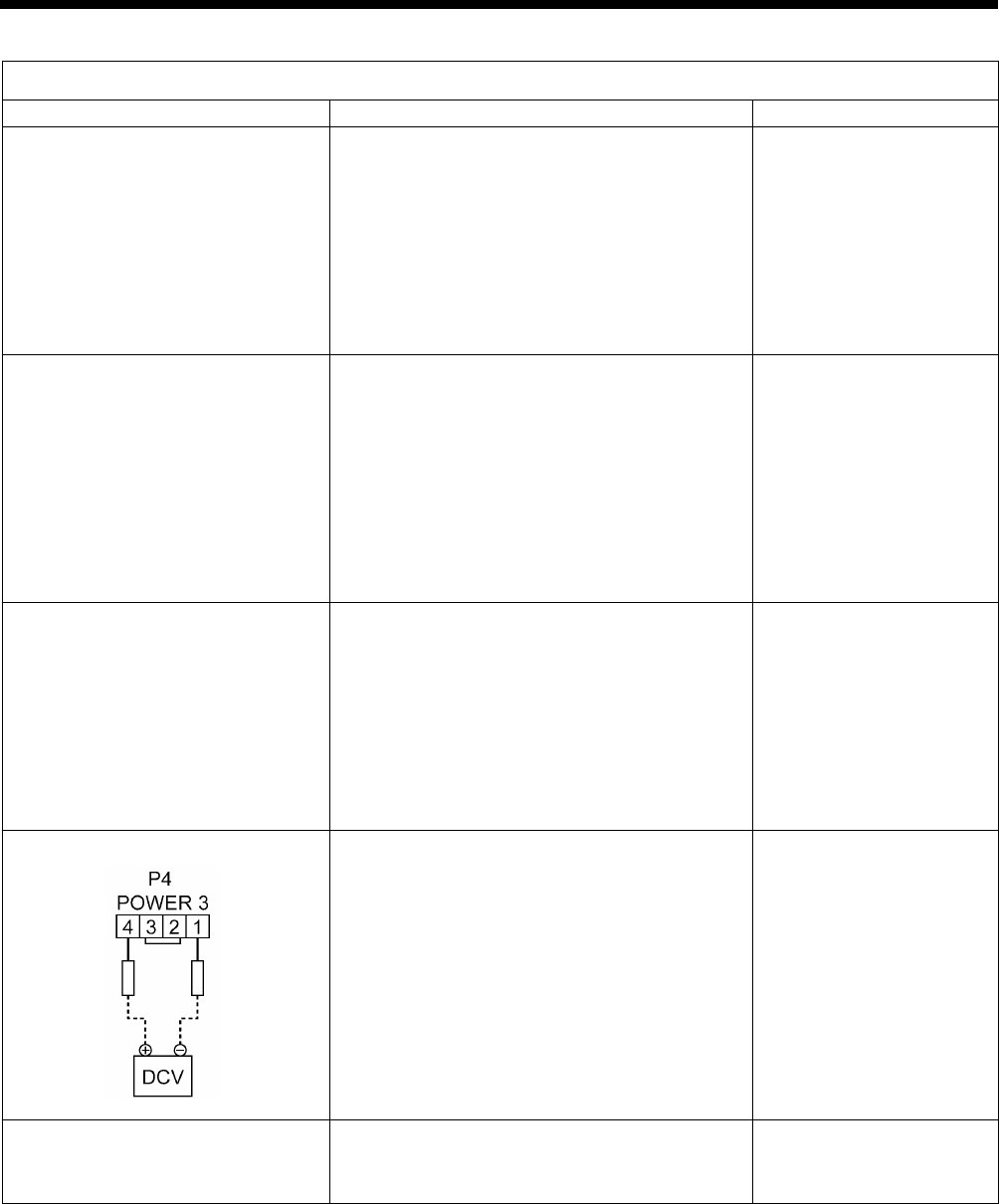
9. ELECTRIC MECHANISM
HE-800B
129
Error status #1 The power indicator does not light when the power is turned on.
Probable causes
Check/ repair/ adjust
Parts to be replaced
6. Malfunction of main PCB
Turn off the power switch, disconnect connector
P4 (POWER3) and P6 (POWER2) from the motor
PCB, and then turn on the power switch and
check LD2 (red) on the power PCB.
OK if illuminated.
(LD1 (red) on power PCB does not illuminate)
After checking, turn off the power switch, wait for
one minute or more, and then insert P4 and P6
into the motor PCB.
Main PCB assembly 800B
7. Malfunction of main PCB 2
Turn off the power switch, disconnect connector
P1 (POWER2) from the main PCB and
connectors P1 (MT-ENC), P2 (MAIN) and P3
(PANEL) from the motor PCB, and then turn on
the power switch and check LD2 (red) on the
power PCB.
OK if illuminated.
After checking, turn off the power switch, wait for
one minute or more, and then insert P1 into the
main PCB and P1, P2 and P3 into the motor PCB.
Main PCB assembly 800B
8. Malfunction of panel PCB
Turn off the power switch, disconnect connector
P1 (POWER2) from the main PCB and
connectors P1 (MT-ENC) and P2 (MAIN) from the
motor PCB, and then turn on the power switch
and check LD2 (red) on the power PCB.
OK if illuminated.
After checking, turn off the power switch, wait for
one minute or more, and then insert P1 into the
main PCB and P1 and P2 into the motor PCB.
LCD panel PCB assembly
Panel harness
9. Poor harness connection
Turn off the power switch, check that connector
P4 (POWER3) is inserted into the motor PCB,
and then turn on the power switch and check the
voltage between terminals 1 and 4 of P4.
OK if approximately 24 V DC.
Power PCB assembly
10. Malfunction of operation panel
Check that connector P3 (PANEL) of the motor
PCB is inserted.
Operation panel assembly
LCD panel PCB assembly
Panel harness
2713B

9. ELECTRIC MECHANISM
HE-800B
130
Error status #2 Error code appears on the display when the power is turned on.
Probable causes
Check/ repair/ adjust
Parts to be replaced
1. If error E015 or E016 is displayed,
there is a poor connection of the
STOP switch.
a. Check that the STOP switch is not stuck
down.
b. Check if there is a harness short-circuit.
c. Check that connector P9 (HEAD-SW) is
inserted into the main P.C. board.
STOP switch
2. If error E025, E035 or E045 is
displayed, the foot switch is still
depressed.
a. Check if the foot switch is still depressed.
b. Check if there is a short-circuit in the harness.
c. Check if connector P12 (PEDAL) is connected
to the motor PCB.
d. Reset the depression stroke for the foot switch
while referring to “7-21. Standard setting for
depression stroke (foot switch)”.
* For a 3-pedal foot switch, the connector for the
main PCB will be P15 (PEDAL).
Treadle unit
3-pedal foot switch assembly
3. If "E055" is displayed, there is a
malfunction of the machine head
switch.
a. Check if the machine head switch is off.
b. Check if there is a broken wire in the harness.
c. Check if connector P14 (HEAD-SW) is
connected to the main PCB.
Switch assembly machine
head
4. If "E065" is displayed, one of the
keys on the operation panel is still
depressed.
a. Check that there is no incorrect sensitivity
when the surface of the panel sheet and the
keys are pressed.
b.
Check that connector P3 (PANEL) is
connected to the motor PCB, and that
connector P1 (MAIN) is connected to the
panel PCB.
Operation panel assembly
LCD panel PCB assembly
Panel harness
5. If “E131” is displayed, there is a
poor connection of the
synchronizer.
Check that connector P11 (RESOLVER) and P1
(MT-ENC) is connected to the motor PCB, and
that connector P6 (MT-ENC) is connected to the
main PCB.
6. If "E401" and "E410" is displayed,
there is a connection fault
between the main PCB, motor
PCB and the panel PCB.
a. Check LD3 (green) on the main PCB.
OK if illuminated.
b. Check LD3 (green) on the motor PCB.
OK if illuminated.
c. Check that connector P5 (MOTOR) is
connected to the main PCB, and that
connector P2 (MAIN) is connected to the
motor PCB.
d.
Check that connector P3 (PANEL) is
connected to the motor PCB, and that
connector P4 (MAIN) is connected to the
panel PCB.
e. Check if there is a broken wire in the harness.
Main PCB assembly 800B
Motor PCB assembly 800B
LCD panel PCB assembly
Connection harness
Panel harness
(Continued on next page.)

9. ELECTRIC MECHANISM
HE-800B
131
Error status #2 Error code appears on the display when the power is turned on.
7. If "E450" or "E452" is displayed,
the machine head memory cannot
be recognized.
a. Check if connector P3 (HEAD-M) is connected
to the main PCB.
b. Check if there is a broken wire in the harness.
8. If error E650 is displayed, there is
a poor connection of the cutter.
a. Check that connector P7
(
SENSOR2
)
is
inserted into the main P.C. board.
b. Check if there is a harness short-circuit.
c. Open the top cover and check the installation
of the cutter sensor.
Cutter sensor
9. If "E700" is displayed, the power
supply voltage is abnormally high.
a. Check that the power supply voltage at the
mains is at the specification voltage plus or
minus 10%.
b. See #1-2.
10. If "E705" is displayed, the power
supply voltage is abnormally low.
a. Check that the power supply voltage at the
mains is at the specification voltage plus or
minus 10%.
b. See #1-2.
Error status #3 “Depress the treadle.” is not displayed when the power switch is turned on.
Probable causes
Check/ repair/ adjust
Parts to be replaced
1. Main software not installed
correctly
Carry out the restore operation by referring to
"4-11. Updating the control program version ".
Operation panel assembly
Panel PCB assembly
Panel harness
2. Poor harness connection
Refer to inspections 9 and 10 in #1.
3. Malfunction of PCB
Check all of the LEDs while referring to step 1 in
#1, and then refer to inspections 5 to 8 in #1
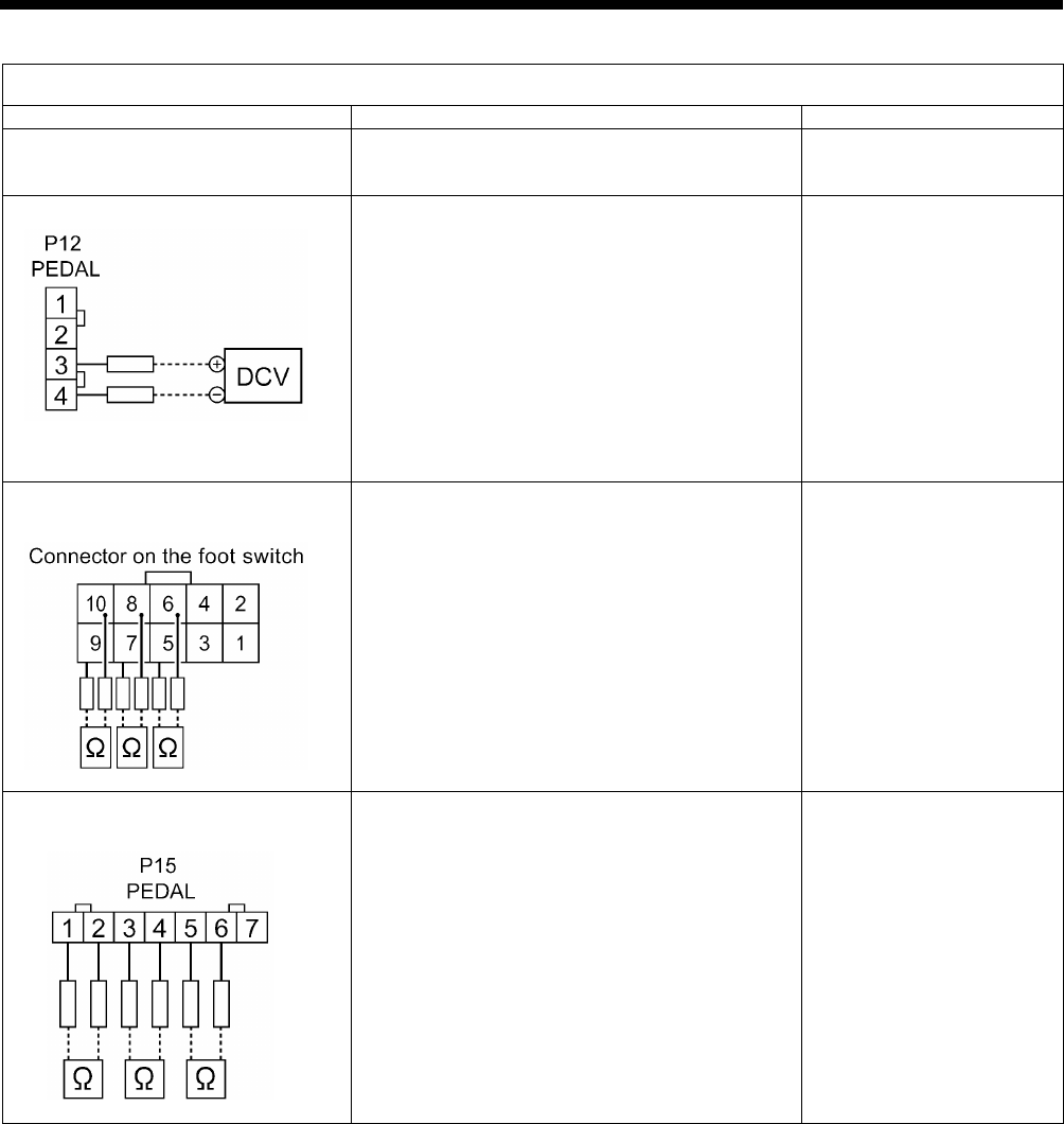
9. ELECTRIC MECHANISM
HE-800B
132
Error status #4 Work clamp does not return to home position during home position detection.
Probable causes
Check/ repair/ adjust
Parts to be replaced
1. Incorrect depression position
adjustment
Adjust the position while referring to “7-21. Setting
method for standard depression strokes”.
2. Malfunction of treadle unit
With the motor PCB connector P12 (PEDAL)
connected, turn on the power and measure the
voltage between pins 3-4 of the cord connector
(No. 3 +, No. 4 -).
OK if the voltage is approximately 2 V at neutral,
approximately 4 V when the foot switch is
depressed as far as it will go, and approximately
0.5 V when it is depressed backward.
Foot switch
3. Malfunction of foot switch and cord
(option)
(Check that the power is turned off.)
Disconnect the foot switch from the foot switch
adapter harness, and measure the voltage
between pins 5-6 and 7-8 of the foot switch
connector. (Check between pins 9-10 if using a
3-pedal foot switch.)
OK if the resistance is normally ∞ ohms but 0
ohms when depressed.
Foot switch
4. Malfunction of foot switch adapter
harness (option)
After checking the foot switch in step 3, connect
the foot switch adapter harness to the foot switch
and measure the voltage between pins 1-2 and
3-4 of connector P15 (PEDAL) of the main PCB.
(Check between pins 5-6 if using a 3-pedal foot
switch.)
(Touch the ohmmeter against the lead wires
without disconnecting the connector.)
OK if the resistance is normally ∞ ohms but 0
ohms when depressed.
Foot switch
Foot switch cord
2956B
2716B
2714B

9. ELECTRIC MECHANISM
HE-800B
133
Error status #5 An error code is displayed during home position detection.
Probable causes
Check/ repair/ adjust
Parts to be replaced
1. If error E130, E131, E132 or E133
is displayed, there is a poor
connection of the synchronizer.
Refer to inspection #2-4.
2. If error E130, E131, E132 or E133
is displayed, there is a poor
connection of the upper shaft
motor.
Check the connection of the relay connector
between the upper shaft motor and the motor
PCB.
3. If error E130, E131, E132 or E133
is displayed, there is a blown fuse.
a. Remove fuses F1 and F2 from the motor PCB
and check the continuity.
OK if there is continuity.
b. If fuses F1 and F2 are blown, check the
resistances between each of the pins of the
relay connector between the upper shaft
motor and the motor PCB, and between the
terminals of the fuses. OK if ∞Ω.
c. If the fuses blow again after they are replaced,
replace the motor PCB.
GFUSE10A-250V
(10A-250V)
Motor PCB assembly 800B
4. If error E130, E131, E132 or E133
is displayed, there is a malfunction
of the motor PCB.
a. Check the synchronizer input while referring to
“3-7. Input checking method”.
OK if the signal turns on and off.
b. If step a. (above) is OK, there is a malfunction
of the motor PCB.
Resolver stator 800 assembly
Motor PCB assembly 800B
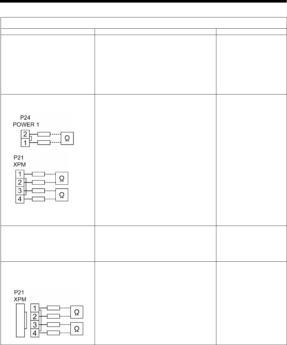
9. ELECTRIC MECHANISM
HE-800B
134
Error status #6 An error code is displayed during home position detection.
Probable causes
Check/ repair/ adjust
Parts to be replaced
1. If zigzagging does not occur and
error E200 is displayed, there is a
malfunction of the power PCB.
Disconnect connectors P1 (POWER2) and P24
(POWER1) from the main PCB, and then turn on
the power switch and check LD1 (red) on the
power PCB.
OK if illuminated.
After checking, turn off the power switch, wait for
one minute or more, and then insert P1 and P24
into the main PCB.
Power PCB assembly
2. If zigzagging does not occur and
error E200 is displayed, there is a
malfunction of the main PCB.
a. Disconnect connector P24 (POWER1) from
the main PCB, and check the continuity
between terminals 1 and 2 of P24.
OK if ∞ ohms.
b. Disconnect connector P21 (XPM) from the
main PCB, and check the continuity between
terminals 1 and 2, 3 and 4 of P21.
OK if ∞ ohms.
c. Insert P21 and P24 into the main PCB, turn on
the power switch and then check LD1 (red) on
the power PCB.
OK if illuminated.
If LD1 is illuminated during the check in step 1
but it does not illuminate when P1 and P24
are connected, there is a malfunction of the
main PCB.
d. Check LD1 (orange) on the main PCB.
OK if illuminated.
Main PCB assembly 800B
3. If zigzagging occurs slightly and
error E200 is displayed, there is a
malfunction of the encoder.
a. Check that connector P17 (X-ENC) is inserted
into the main PCB and that the color matches.
b. Check the encoder input while referring to
"3-7. Input checking method".
Pulse motor zigzag assembly
Main PCB assembly 800B
4. If zigzagging does not occur and
error E200 is displayed, there is a
malfunction of the pulse motor or
cord.
a. Disconnect the main PCB connector P21
(XPM) and measure the resistance between
pins 1-2 and 3-4 of the cord connector.
OK if 2-3 ohms.
b. If step a. (above) is OK, there is a malfunction
of the main PCB.
Pulse motor zigzag assembly
Main PCB assembly 800B
2717B
2718B
2719B

9. ELECTRIC MECHANISM
HE-800B
135
Error status #7 An error code is displayed during home position detection.
Probable causes
Check/ repair/ adjust
Parts to be replaced
1. If feeding does not occur and error
E210 is displayed, there is a
malfunction of the power PCB.
Disconnect connectors P1 (POWER2) and P24
(POWER1) from the main PCB, and then turn on
the power switch and check LD1 (red) on the
power PCB.
OK if illuminated.
After checking, turn off the power switch, wait for
one minute or more, and then insert P1 and P24
into the main PCB.
Power PCB assembly
2. If feeding does not occur and error
E210 is displayed, there is a
malfunction of the main PCB.
a. Disconnect connector P24 (POWER1) from
the main PCB, and check the continuity
between terminals 1 and 2 of P24.
OK if ∞ ohms.
b. Disconnect connector P22 (YPM) from the
main PCB, and check the continuity between
terminals 1 and 2, 3 and 4 of P22.
OK if ∞ ohms.
c. Insert P22 and P24 into the main PCB, turn on
the power switch and then check LD1 (red) on
the power PCB.
OK if illuminated.
If LD1 is illuminated during the check in step 1
but it does not illuminate when P1 and P24
are connected, there is a malfunction of the
main PCB.
d. Check LD1 (orange) on the main PCB.
OK if illuminated.
Main PCB assembly 800B
3. If feeding occurs slightly and error
E210 is displayed, there is a
malfunction of the encoder.
a. Check that connector P18 (Y-ENC) is inserted
into the main PCB and that the color matches.
b. Check the encoder input while referring to
"3-7. Input checking method".
Pulse motor feed assembly
Main PCB assembly 800B
4. If zigzagging does not occur and
error E210 is displayed, there is a
malfunction of the pulse motor or
cord.
a. Disconnect the main PCB connector P22
(YPM) and measure the resistance between
pins 1-2 and 3-4 of the cord connector.
OK if 2-3 ohms.
b. If step a. (above) is OK, there is a malfunction
of the main PCB.
Pulse motor feed assembly
Main PCB assembly 800B
2717B
2720B
2721B
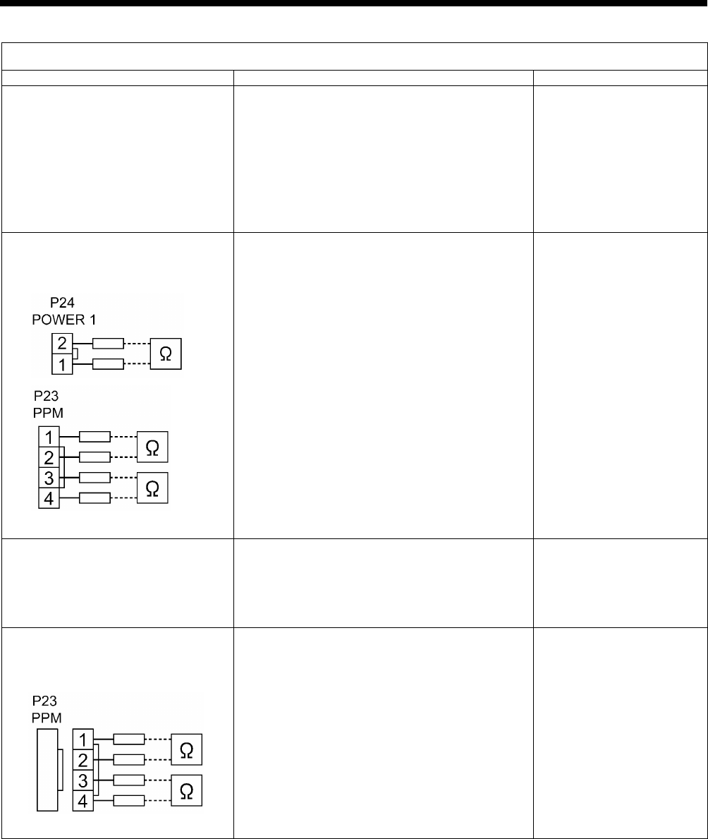
9. ELECTRIC MECHANISM
HE-800B
136
Error status #8 An error code is displayed during home position detection.
Probable causes
Check/ repair/ adjust
Parts to be replaced
1. If the work clamp pulse motor
does not operate and "E300" is
displayed, there is a malfunction of
the power PCB.
Disconnect connectors P1 (POWER2) and P24
(POWER1) from the main PCB, and then turn on
the power switch and check LD1 (red) on the
power PCB.
OK if illuminated.
After checking, turn off the power switch, wait for
one minute or more, and then insert P1 and P24
into the main PCB.
Power PCB assembly
2. If the work clamp pulse motor
does not move and "E300" is
displayed, there is a malfunction of
the main PCB.
a. Disconnect connector P24 (POWER1) from
the main PCB, and check the continuity
between terminals 1 and 2 of P24.
OK if ∞ ohms.
b. Disconnect connector P23 (PPM) from the
main PCB, and check the continuity between
terminals 1 and 2, 3 and 4 of P23.
OK if ∞ ohms.
c. Insert P23 and P24 into the main PCB, turn on
the power switch and then check LD1 (red) on
the power PCB.
OK if illuminated.
If LD1 is illuminated during the check in step 1
but it does not illuminate when P1 and P24
are connected, there is a malfunction of the
main PCB.
d. Check LD1 (orange) on the main PCB.
OK if illuminated.
Main PCB assembly 800B
3. If the work clamp pulse motor
moves slightly and "E300" is
displayed, there is a malfunction of
the encoder.
a. Check that connector P19 (P-ENC) is inserted
into the main PCB and that the color matches.
b. Check the encoder input while referring to
"3-7. Input checking method".
Pulse motor work clamp
assembly
Main PCB assembly 800B
4. If the work clamp pulse motor
does not move and "E300" is
displayed, there is a malfunction of
the pulse motor and cord.
a. Disconnect the main PCB connector P23
(PPM) and measure the resistance between
pins 1-2 and 3-4 of the cord connector.
OK if 2-3 ohms.
b. If step a. (above) is OK, there is a malfunction
of the main PCB.
Pulse motor work clamp
assembly
Main PCB assembly 800B
2717B
2722B
2723B

9. ELECTRIC MECHANISM
HE-800B
137
Error status #9 Work clamp does not rise during home position detection.
Probable causes
Check/ repair/ adjust
Parts to be replaced
1. Incorrect work clamp home position
adjustment
a. Adjust the home position while referring to
"7-2. Adjusting the home position".
b. Check if the work clamp is touching something
else.
2. Incorrect mechanism adjustment
Check if the work clamp mechanism, upper
thread trimming mechanism and lower thread
trimming mechanism are moving stiffly.
Error status #10 Work clamp does not drop during threading mode.
Probable causes
Check/ repair/ adjust
Parts to be replaced
1. Incorrect work clamp home position
adjustment
a. Adjust the home position while referring to
"7-2. Adjusting the home position".
b.
Check if the work clamp/button clamp is
touching anything.
2. Incorrect mechanism adjustment
Check if the work clamp mechanism, upper
thread trimming mechanism and lower thread
trimming mechanism are moving stiffly.
Error status #11 The THREAD indicator does not illuminate during threading mode.
Probable causes
Check/ repair/ adjust
Parts to be replaced
Malfunction of panel PCB
Check that connector P3 (PANEL) is connected to
the motor PCB, and that connector P1 (MAIN) is
connected to the panel PCB.
LCD panel PCB assembly
Panel harness
Error status #12 Zigzagging does not move slowly one stitch at a time during test feeding.
Probable causes
Check/ repair/ adjust
Parts to be replaced
1. Malfunction of foot switch and cord
See #4.
2. Malfunction of zigzag mechanism
See #6.
Error status #13 The feed mechanism does not move slowly one stitch at a time during test feeding.
Probable causes
Check/ repair/ adjust
Parts to be replaced
1. Malfunction of foot switch and cord
See #4.
2. Malfunction of feed mechanism
See #7.
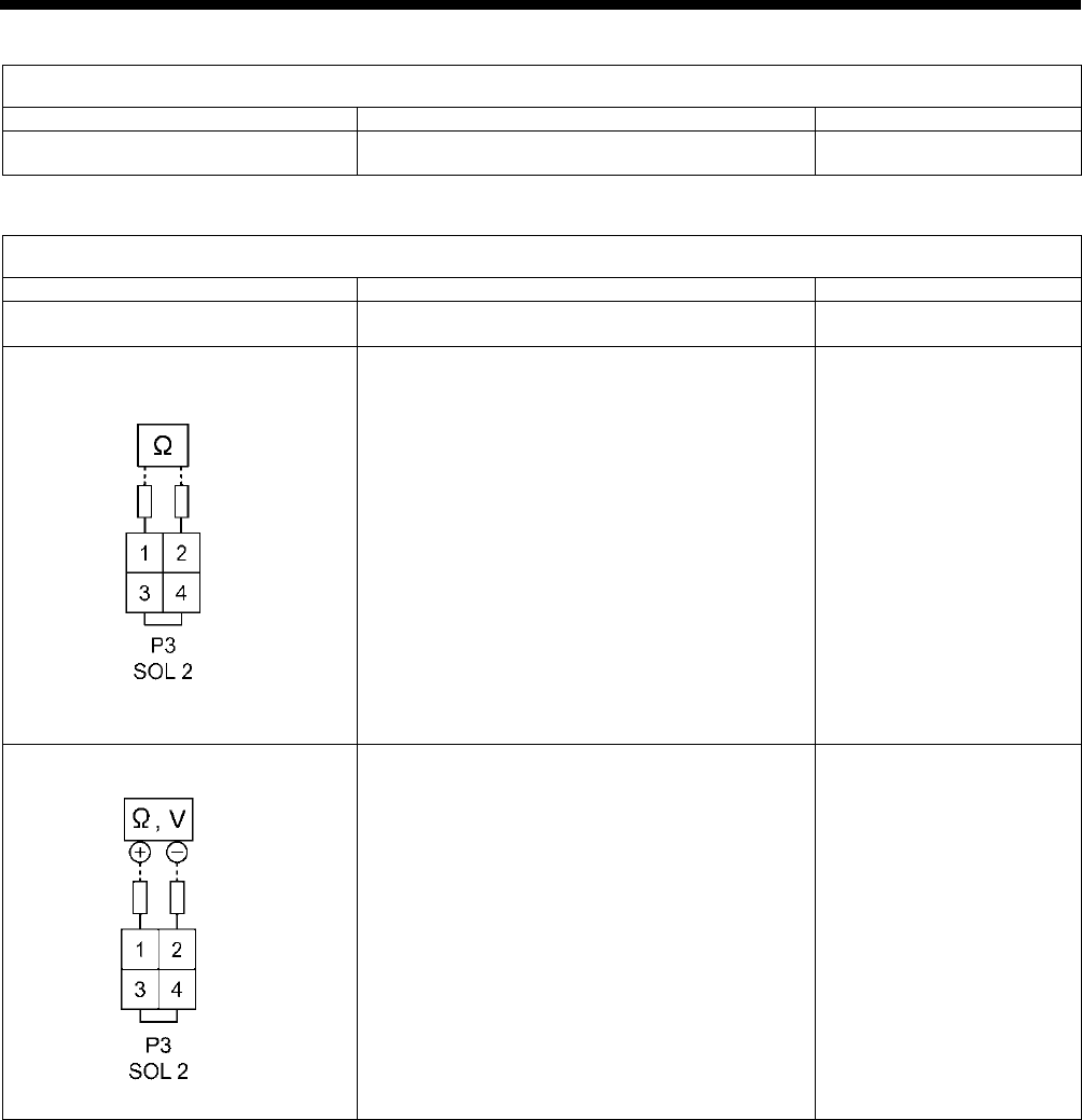
9. ELECTRIC MECHANISM
HE-800B
138
Error status #14 Feeding and zigzagging do not move continuously during test feeding.
Probable causes
Check/ repair/ adjust
Parts to be replaced
Malfunction of foot switch and cord
See #4.
Error status #15 Tension release does not operate during test feeding.
Probable causes
Check/ repair/ adjust
Parts to be replaced
1. Poor connector connection
Check that main PCB connector P2 (SOL1) and
P3 (SOL2) is connected.
2. Malfunction of tension release
solenoid
Disconnect main PCB connector P3 (SOL2) and
measure the resistance between pins 1-2 of the
cord connector.
OK if 6-8 ohms.
Tension release solenoid
3. Malfunction of main PCB.
a. Turn on the power switch and check LD2
(green) on the main PCB.
OK if illuminated.
b. With connector P3 (SOL2) disconnected from
the main PCB, check the continuity between
terminals 1 and 2 of connector P3 on the
main PCB.
OK if ∞ ohms.
c. With main PCB connector P3 (SOL2)
connected, turn on the power and carry out
sewing, and measure the voltage between
pins 1-2 of connector P3 (SOL2).
OK if there is voltage output momentarily
after sewing stops.
Main PCB assembly 800B
2727B
0651D

9. ELECTRIC MECHANISM
HE-800B
139
Error status #16 Upper shaft motor does not operate during sewing.
Probable causes
Check/ repair/ adjust
Parts to be replaced
1. If “E111”, “E130”, “E131”, “E132” or
“E133” is displayed after the
sewing machine operates, there is
a poor connection of the
synchronizer.
Check that connectors P11 (RESOLVER) and P1
(MT-ENC) of the motor PCB and connector P6
(MT-ENC) of the main PCB are inserted.
2. If error E111, E130, E131, E132 or
E133 is displayed after the sewing
machine operates, there is a poor
connection of the upper shaft
motor.
Check the connection of the relay connector
between the upper shaft motor and the motor
PCB.
3. If “E111”, “E130”, “E131”, “E132” or
“E133” is displayed after the
sewing machine operates,
interference is causing operating
errors.
Check that the ground wire is securely connected
and that the sewing machine is not close to any
equipment that generates strong electrical
interference.
4. If “E111”, “E130”, “E131”, “E132” or
“E133” is
displayed after the
sewing machine operates, there is
a malfunction of the motor PCB.
Refer to steps 1 to 4 in #5.
Resolver stator assembly
Motor PCB assembly 800B
5. If error E111, E130, E132 or E133
is displayed after the sewing
machine operates, there
is a
malfunction of the motor PCB or of
the upper shaft motor.
If an error occurs after inspection steps 1 to 4
above have been carried out, there is a
malfunction of the machine motor.
Motor 800 assembly
6. If "E121" is displayed after the
sewing machine operates, there is
a malfunction of a component.
1
)
If the area around the motor is not warm,
refer to inspections 1 to 5 in #16.
2) If the area around the motor is warm, turn the
pulley by hand and check that it is not stiff. If
it is stiff, adjust while referring to “6-8. Upper
shaft and tension pulley mechanisms”. If it is
not stiff, there is a malfunction of the machine
motor.
Resolver stator 800 assembly
Motor PCB assembly 800B
Motor 800 assembly
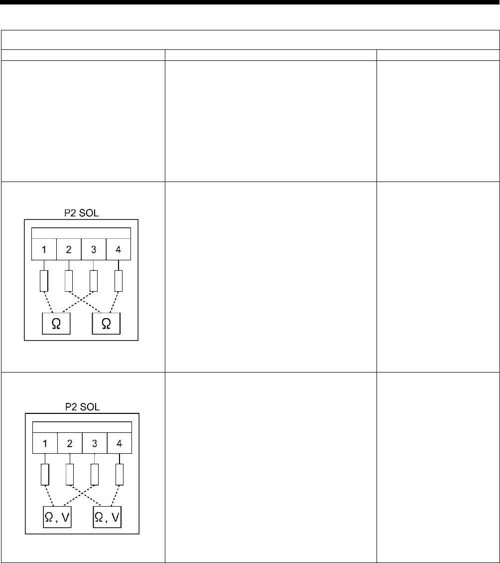
9. ELECTRIC MECHANISM
HE-800B
140
Error status #17 Upper shaft motor does not operate during sewing.
Probable causes
Check/ repair/ adjust
Parts to be replaced
1. Poor connector contact
Check that connector P31 (CUTTER) is inserted
into the main PCB, that connectors P1 (POWER),
P2 (SOL) and P3 (MAIN) are inserted into the
cutter PCB, and that connector P5 (CUTTER) is
inserted into the power PCB.
2. Malfunction of cutter solenoid
Disconnect connector P2 (SOL) from the cutter
PCB, and measure the resistances between pins
1 and 3 and pins 2 and 4 of the cord-side
connector.
OK if 6Ω to 8Ω between 1 and 3, and 13Ω to 15Ω
between 2 and 4.
Cutter solenoid assembly
3. Malfunction of cutter PCB
a. Turn off the power switch, disconnect
connector P2 (SOL) from the cutter PCB, and
then check the continuity between terminals
1 and 3 and terminals 2 and 4 of connector
P2 on the cutter PCB.
OK if ∞Ω
b. Insert connector P2 (SOL) into the cutter
PCB, turn on the power switch and carry out
sewing, and measure the voltages between
terminals 1 and 3 and terminals 2 and 4 of
connector P2.
OK if voltage is output momentarily at the
sewing end.
Cutter PCB assembly
0780D
0781D
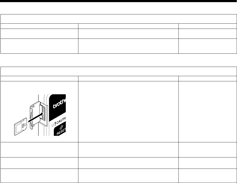
9. ELECTRIC MECHANISM
HE-800B
141
Error status #18 Needle bar does not stop at the needle up position (“UP” is frequently displayed after sewing)
Probable causes
Check/ repair/ adjust
Parts to be replaced
1. Incorrect adjustment
Adjust while referring to "7-2. Adjusting the home
position”.
2. Problem with upper shaft motor
operation
Refer to steps 1 to 5 in #16
Resolver stator 800 assembly
Motor PCB assembly 800B
Motor 800 assembly
Error status #19 SD card read/write mode cannot be activated.
Probable causes
Check/ repair/ adjust
Parts to be replaced
1. If error E422 or E425 is displayed,
the SD card is inserted incorrectly.
a. Check the direction of insertion of the SD
card.
(Insert the card so that it matches the direction
of the pattern on the card cover.)
b. Check the insertion of the SD card.
2. If “E424” is displayed, the SD card
is incorrectly formatted.
Check the format of the SD card.
(Carry out 16-sector formatting.)
3. Malfunction of SD card
Use a PC to check if the contents of the SD card
can be read.
4. Malfunction of operation panel
See #12.
LCD panel PCB assembly
Panel harness
2650B
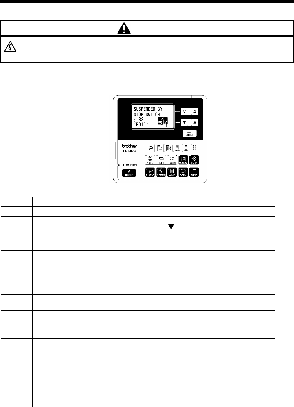
10. TABLE OF ERROR CODES
HE-800B
142
10. TABLE OF ERROR CODES
DANGER
Wait at least 5 minutes after turning off the power switch and disconnecting the power cord from the wall outlet before
opening the control box
cover. Touching areas where high voltages are present will result in serious injury from
electric shocks.
If a problem should occur with the sewing machine, the buzzer will sound and an error code and error message will appear in
the display.
Follow the remedy procedure to eliminate the cause of the problem.
Switch-related errors
Code
Cause
Remedy
E010
Stop switch was pressed during standby.
Remove your finger from the stop switch (so that it is off).
E011 Stop switch was pressed during sewing.
Press the RESET key to clear the error.
* Press the
key to move the needle and the work
clamp so that you can continue sewing.
*
If not continuing sewing, press the RESET key once
more.
E012
Stop switch was pressed while sewing
machine was operating other than during
sewing.
Press the RESET key to clear the error.
(Home position detection will be carried out automatically.)
E015
The stop switch was still pressed when
the power was turned on, or there is a
problem with the stop switch connection.
Turn off the power and check the connection of the stop
switch connector P9 at the main P.C. board.
E016 Problem with the stop switch connection.
Turn off the power and check the connection of the stop
switch connector P9 at the main P.C. board.
E025
Treadle was still depressed to the 2nd
step when the power was turned on, or
treadle connection is faulty.
(Start switch if a triple pedal is being used)
Turn off the power, and then check that connector P12 on
the motor P.C.
board is properly connected. (Connector
P15 on the main P.C. board if a triple pedal is being used)
E035
Treadle was still depressed to the 1st step
when the power was turned on, or treadle
connection is faulty.
(Work clamp switch if a triple pedal is
being used)
Turn off the power, and then check that connector P12 on
the motor P.C. board is properly connected. (Connector
P15 on the main P.C. board if a triple pedal is being used)
E045
Treadle was still depressed backward
when the power was turned on, or treadle
connection is faulty.
(Work clamp lifter switch if a triple pedal is
being used)
Turn off the power, and then check that connector P12 on
the motor P.C. board is properly connected. (Connector
P15 on the main P.C. board if a triple pedal is being used)
4933M
Flashing

10. TABLE OF ERROR CODES
HE-800B
143
Code
Cause
Remedy
E050
Machine head tilting was detected
immediately before the sewing machine
started operating.
Turn off the power, and then return the machine head to its
original position.
Check that safety switch connector P14 on the main P.C.
board is properly connected.
E051
Machine head tilting was detected while
the sewing machine was operating.
Turn off the power, and then return the machine head to its
original position.
Check that safety switch connector P14 on the main P.C.
board is properly connected.
E055
Machine head tilting was detected when
the power was turned on.
Turn off the power, and then return the machine head to its
original position.
Check that safety switch connector P14 on the main P.C.
board is properly connected.
E065
An operation panel key was still being
pressed when the power was turned on,
or key is faulty.
Turn off the power and check the operation panel.
Upper shaft motor-related errors
Code
Cause
Remedy
E110
Pulley is not in needle up stop position
during standby when work clamp is
lowered.
Turn off the power, and then open the slide cover. Align
the mark (A) on the pulley within the edges of the mark (B)
on the motor cover.
E111
The sewing machine could not stop
correctly at the needle
up stop position
after sewing.
Turn off the power, and then check that there are no
problems with the cutter mechanism, the thread trimming
mechanism and the upper shaft motor mechanism.
E112
The needle bar dropped during home
position detection or while
the SD card
was being accessed.
Turn off the power, and then turn it back on again.
*
If this error occurs when the work clamp is not lowered,
the work clamp will drop automatically in order to
prevent interference between the needle and the lower
thread retainer.
E113
Pulley is not in needle up stop position
during standby when work clamp is not
lowered.
Turn off the power, and then open the slide cover. Align the
mark (A) on the pulley within the edges of the mark (B) on
the motor cover. (Refer to the diagram for “E110” above.)
*
If this error occurs, the work clamp will drop
automatically in order to prevent interference between
the needle and the lower thread retainer.
E130
Upper shaft motor stopped due to a
problem, or synchronizer is faulty.
Turn off the power, and then open the slide cover. Turn
the pulley to check if the machine has locked up.
Check that the upper shaft motor 4-pin (UVW) connector
and synchronizer connector P11 on the motor P.C. board
are properly connected.
E131 Synchronizer is not connected correctly.
Turn off the power, and then check that synchronizer
connector P11 on the motor P.C. board is properly
connected.

10. TABLE OF ERROR CODES
HE-800B
144
Code
Cause
Remedy
E132
Problem detected with upper shaft motor
operation.
Turn off the power, and then check that synchronizer
connector P11 on the motor P.C. board is properly
connected.
E133
Upper shaft motor stopping position is
incorrect. (During automatic needle lifting)
Turn off the power, and then check that synchronizer
connector P11 on the motor P.C. board
is properly
connected.
E150
Upper shaft motor is overheating, or
temperature sensor is faulty.
Turn off the power, and then check the upper shaft motor.
Feed mechanism-related errors
Code
Cause
Remedy
E200
Needle zigzag motor home position
cannot be detected.
Needle zigzag motor, needle zigzag
sensor or needle zigzag encoder signal is
not connected correctly.
Turn off the power, and then check that the needle zigzag
sensor and needle zigzag encoder connector P17 and the
needle zigzag motor connector P21 on the main P.C.
board are properly connected.
E201
Needle zigzag motor stopped due to a
problem.
Turn off the power, and then check if there are any
problems in the needle zigzag direction.
E210
Feed motor home position cannot be
detected.
Feed motor, feed sensor or feed encoder
signal is not connected correctly.
Turn off the power, and then check that the feed sensor
connector P8, feed encoder connector P18 and feed
motor connector P22 on the main P.C. board are properly
connected.
E211 Feed motor stopped due to a problem.
Turn off the power, and then check if there are any
problems in the feed direction.
Work clamp-related errors
Code Cause Remedy
E300
Work clamp motor home position cannot
be detected.
Work clamp motor, work clamp sensor or
work clamp encoder signal is not
connected correctly.
Turn off the power, and then check that the work clamp
sensor and work clamp encoder connector P19 and the
work
clamp motor connector P23 on the main P.C. board
are properly connected.
E301
Work clamp motor stopped due to a
problem.
Turn off the power, and then move the work clamp up and
down and check that it moves smoothly.
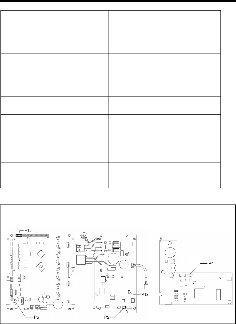
10. TABLE OF ERROR CODES
HE-800B
145
Communication and memory-related errors
Code
Cause
Remedy
E401
Communication error detected between
the main P.C. board and the motor P.C.
board when the power was turned on.
Turn off the power, and then check that connector P5 on
the main P.C. board and connector P2 on the motor P.C.
board are properly connected.
E410
Communication error detected between
the main P.C. board and the panel P.C.
board.
Turn off the power, and then check that connector P4 on
the panel P.C. board and operation panel connector P3 on
the motor P.C. board are properly connected.
E411
Communication error detected between
the main P.C. board and the motor P.C.
board.
Turn off the power, and then check that connector P5 on
the main P.C. board and connector P2 on the motor P.C.
board are properly connected.
E422
An error occurred while reading from the
SD card.
Press the RESET key to clear the error.
Check the data on the SD card.
E424 Insufficient free space on the SD card.
Press the RESET key to clear the error.
Use a different SD card.
E425 An error occurred while writing to the SD
card.
Press the RESET key to clear the error.
Check if the media is write-protected and if it has enough
free space.
E430
Problem with flash memory on main P.C.
board.
Turn the power off and then back on again.
E440
Problem with EEPROM on main P.C.
board.
Turn the power off and then back on again.
E450
Model selection cannot be read from the
machine head memory.
Turn off the power, and then check that the correct
machine head memory is connected.
Check that the machine head memory connector P16 on
the main P.C. board is properly connected.
E452 Machine head memory is not connected.
Turn off the power, and then check that machine head
memory connector P16 on the main P.C. board is properly
connected.
E453
Problem with machine head memory.
Turn the power off and then back on again.
[P.C. board and connector positions]
<Control box> <Operation panel>
Main P.C. board Motor P.C. board Panel P.C. board
4887M
4888M

10. TABLE OF ERROR CODES
HE-800B
146
Software-related errors
Code Cause Remedy
E512
Maximum number of stitches for a single
program (999 stitches) exceeded.
When the power is turned off and then back on, the
zigzag pitch will be set automatically to x1.5 in order to
reduce the number of stitches.
E582
Error in memory switch version detected.
Turn off the power and carry out level 2 initialization.
E583
Error in parameter data version detected.
Turn off the power and carry out level 1 initialization.
Device-related errors
Code
Cause
Remedy
E600 Upper thread breakage occurred.
Thread the upper thread, and then press the RESET key
to clear the error.
* Press the
key to move the needle and the work
clamp so that you can continue sewing.
*
If not continuing sewing, press the RESET key once
more.
E650 Cutter is not at home position.
(Cutter is lowered.)
Turn off the power, and then check if there are any
problems with the cutter mechanism.
Check that cutter solenoid connector P2 on the cutter P.C.
board is properly connected.
E651 Cutter has not operated.
(Does not drop.)
Turn off the power, and then check that cutter sensor
connector P7 on the main P.C. board and cutter solenoid
connector P2 on the cutter P.C. board are properly
connected.
P.C. board-related errors
Code
Cause
Remedy
E700
Abnormal rise in power supply voltage.
Turn off the power and check the input voltage.
E701
Abnormal rise in upper shaft motor drive
voltage.
Turn off the power, and then check the voltage.
E705
Abnormal drop in power supply voltage.
Turn off the power and check the input voltage.
E710
Abnormal current detected in upper shaft
motor.
Turn off the power, and then check if there are any
problems with the upper shaft motor.
E711 Abnormal current detected in pulse motor.
Turn off the power, and then check if there are any
problems with the pulse motor.

10. TABLE OF ERROR CODES
HE-800B
147
Version updating errors
Code Cause Remedy
E870
No control program for the operation
panel is present.
Load the control program for the operation panel from the
SD card.
E880
Version update requests cannot be
received.
Turn off the power, and then check that
there are no
problems with the wiring and the P.C. boards inside the
control box.
E881 Communication error was detected during
version update.
Turn off the power, and then repeat the version update
procedure.
If the error continues to occur, turn off the power, and then
check that there are no problems with the wiring and the
P.C. boards inside the control box.
E883
No control program is present on the SD
card.
Check that the control program has been saved into the
correct folder.
E884 There is a problem
with the control
program. Write the correct file onto the SD card.
E885
Writing of the control program cannot
begin.
Turn off the power, and then check that there are no
problems with the wiring and the P.C. boards inside the
control box which are to hav
e their firmware versions
updated.
E886
Data error occurred during writing of the
control program.
Turn off the power, and then check that there are no
problems with the wiring and the P.C. boards inside the
control box which are to have their firmware versions
updated.
E887 Error occurred during writing of the control
program.
Turn off the power, and then check that there are no
problems with the wiring and the P.C. boards inside the
control box which are to have their firmware versions
updated.
If an error code that is not listed above appears or if carrying out the specified remedy does not solve the problem,
contact the place of purchase.
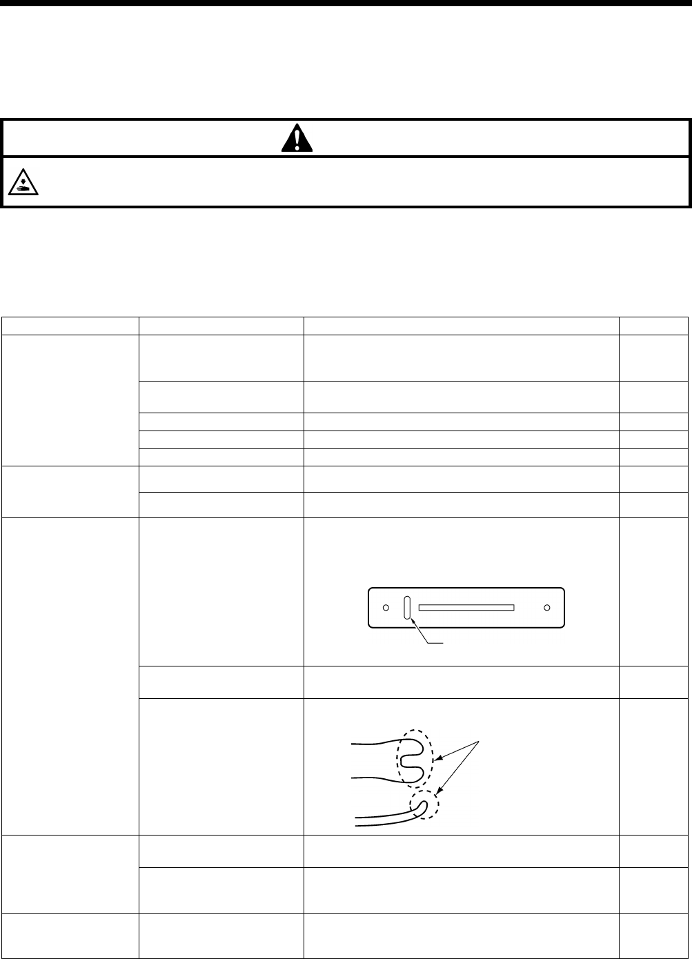
HE-800B
11. TROUBLESHOOTING
148
11. TROUBLESHOOTING
• Please check the following points before calling for repairs or service.
• If the following remedies do not fix the problem, turn off the power switch and consult a qualified technician or the place of
purchase.
CAUTION
Turn off the power switch and disconnect the power cord before carrying out troubleshooting, otherwise the
machine may operate if the treadle is depressed by mistake, which could result in injury.
11-1. Upper thread breakage
Items with a “*” in the “Page” column should only be handled by a qualified technician.
Cause
Check
Remedy
Page
Needle
Needle facing
As viewed from the direction of the face plate, attach
the needle so that the groove of the needle faces
frontward.
91
Needle installation height
Insert the end of the needle shank so that it touches
the top edge of the needle hole of the needle bar.
–
Bent needle
Replace needle.
–
Blunt needle tip or burr
Replace needle.
–
Needle and thread
Replace needle that fits the thread.
–
Threading Upper thread threading Thread the upper thread correctly. INSTRUCTION
MANUAL CD
Lower thread threading
Thread the lower thread correctly.
INSTRUCTION
MANUAL CD
Thread path
Flaw or abrasion on the
thread path
Polish with buff or replace the part.
Especially, pay attention to finishing around needle
plate hole.
–
Flaw on the rotary hook tip
and rotary hook edge
Polish with buff or replace the part.
–
Flaw on the rotary hook
holder
Polish with buff or replace the part.
91
Thread tension
Zigzag thread upper thread
tension
Adjust the upper thread tension appropriately.
INSTRUCTION
MANUAL CD
Bar tack thread upper
thread tension
Adjust the upper thread tension while checking
stitches.
(The stitches on top are the upper thread and
the stitches underneath are the bobbin thread.)
INSTRUCTION
MANUAL CD
Thread take-up spring Thread take-
up spring
tension and height
Loosen the thread take-up spring tension or lower the
height to such a degree that does not cause double
hooking. Adjust it while checking bar tacking stitches.
INSTRUCTION
MANUAL CD
(Continued on next page)
3996Q
3997Q
Needle plate hole
Adjust the rotary hook
overlap amount.
Check flaw here
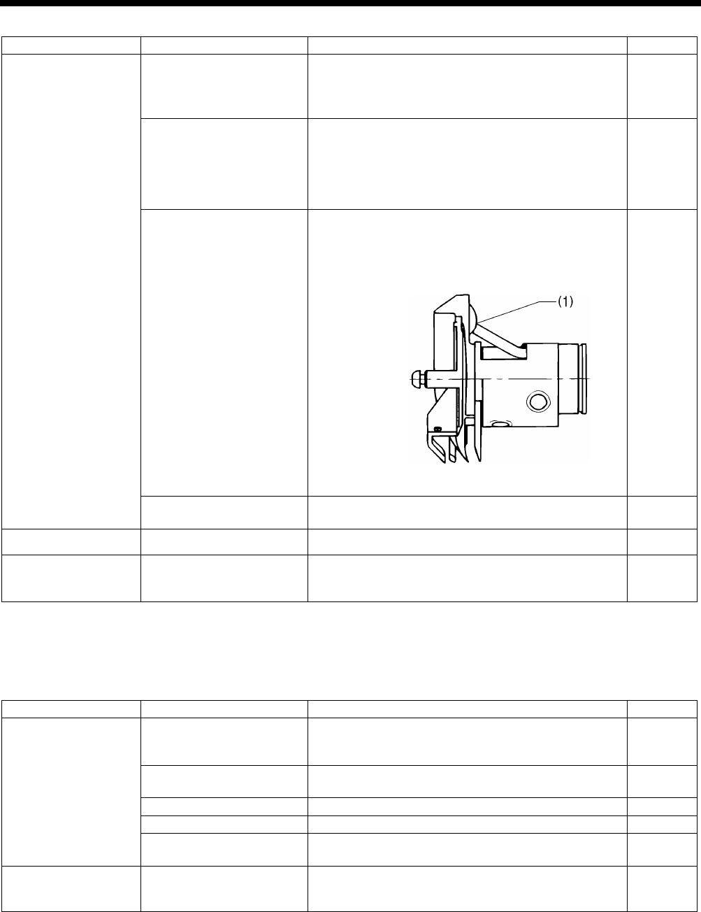
HE-800B
11. TROUBLESHOOTING
149
Cause
Check
Remedy
Page
Rotary hook
Needle bar height and
needle bar lift amount
(The gauge is an option
part.)
1. Adjust the needle bar height to “1” on the gauge.
2.
Adjust the needle and rotary hook timing to “2” on
the gauge.
88
89
Gap
between the needle
and the tip of the rotary
hook
Adjust the gap between the needle and the rotary hook
tip to 0.01 - 0.08 mm. (Adjust to as large as possible
without causing skipped stitches to occur.)
* Move the needle bar to the left and right with your
finger, and check that the tip of the rotary hook does
not strike the needle.
91
Rotary hook lubrication
・
Too small quantity of lubrication oil will cause thread
breakage. Adjust the quantity of lubrication oil.
・The lubrication holes (1)
between rotary hook and
rotary hook joint do not match up.
109
81
Thread twisted around
rotary hook
Remove any twisted thread from the inner and rotary
hook.
–
Upper thread amount
Arm thread guide position
Adjust the arm thread guide position.
INSTRUCTION
MANUAL CD
Bobbin case
Damaged outside of
bobbin case and bent
bobbin holder spring, etc.
Polish with buff or replace the part.
* Use the HE-800B bobbin case. –
11-2. Skipped stitches
Items with a “*” in the “Page” column should only be handled by a qualified technician.
Cause
Check
Remedy
Page
Needle
Needle facing
As viewed from the direction of the face plate, attach
needle so that the groove of the needle faces
frontward.
91
Needle installation height Insert
the end of the needle shank so that it touches
the top edge of the needle hole of the needle bar.
–
Bent needle
Replace needle.
–
Blunt needle tip or burr
Replace needle.
–
Thin needle Use a needle with a count that matches the thread and
material.
–
Thread take-up spring
Thread take-up spring
tension and height
Loosen the thread take-up spring tension or lower the
height to such a degree that does not cause double
hooking. Adjust it while checking bar tacking stitches.
INSTRUCTION
MANUAL CD
(Continued on next page)
4894M
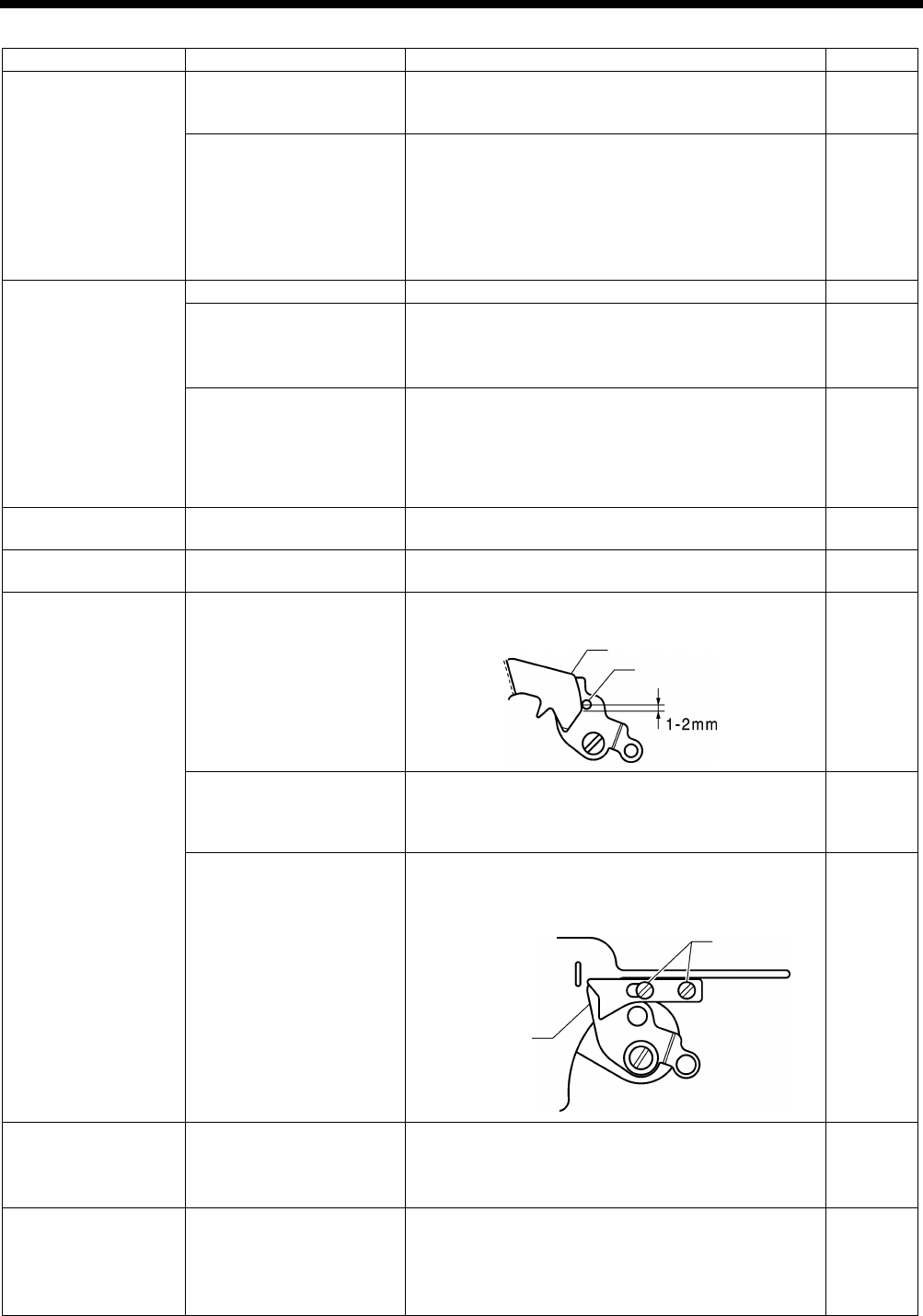
HE-800B
11. TROUBLESHOOTING
150
Cause
Check
Remedy
Page
Work clamp Work clamp pressure Increase work clamp pressure.
*
The standard height of the adjustment screw is
approximately 30 mm, so tighten it further than this.
91
Relation between work
clamp
assembly and
sewing length
・
Replace work clamp assembly that fits for sewing
length.
・
When using knits or woven materials, replace the
parts with the -3 specification parts:
Length feed plate (for specification -
3), work clamp
assembly (for knits), needle
plate 1.2 (for
specification -3)
–
Rotary hook
Blunt rotary hook tip
Polish with buff or replace the part.
–
Needle bar height and
needle bar lift amount
(The gauge is an option
part.)
1. Adjust the needle bar height to “1” on the gauge.
2. Adjust the needle
and rotary hook timing to “2” on
the gauge. 89
Gap between the needle
and the tip of the rotary
hook
Adjust the gap between the needle and the rotary hook
tip to 0.01 - 0.08 mm. (Adjust to as large as possible
without causing skipped stitches to occur.)
*
Move the needle bar to the left and right with your
finger, and check that the tip of the rotary hook does
not strike the needle.
91
Thread tension
Zigzag thread upper thread
tension
Adjust the upper thread tension appropriately.
INSTRUCTION
MANUAL CD
Needle bar play
Vertical and longitudinal
needle bar play
Reduce the needle bar play, or replace the parts.
–
Lower thread clamp Lower thread retainer cam
Lower thread retainer cam should be sitting firmly on
lower thread clamp plate roller.
104
Thread scraps and dust
blocking area around lower
thread clamp and lower
thread presser
Clean around the lower thread presser.
–
Lower thread clamping
force
・
If the lower thread clamp and lower thread presser
are bent, replace them.
・Check that the screws are tightened.
–
Needle plate
Relation between material
and needle plate
・When using knit material, replace with the -3 needle
plate.
・Replace with a needle plate with a smaller needle
hole.
–
Joint sewing
Angle of work clamp
means that material is not
being clamped.
・
Replace with short work clamp that matches the
sewing length.
・Use the accessory auxiliary sheet.
・
Process the work clamp assembly to match the joint
section. (Attach or remove rubber.)
–
100
–
3999Q
3998Q
Roller
Cam
Screw
Lower thread
clamp
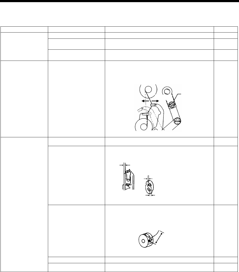
HE-800B
11. TROUBLESHOOTING
151
11-3. Uneven seams (1) …… At the sewing start
Items with a “*” in the “Page” column should only be handled by a qualified technician.
Cause
Check
Remedy
Page
Upper thread trimmer
Installation height
Adjust the upper thread trimmer installation height.
100
Upper thread trimmer
opening timing
Adjust to an appropriate opening timing.
101
Upper thread trimmer
operation
Apply grease to the inclined face of the opening cam.
101
Upper thread feeding
Thread take-up amount
Loosen the screw to decrease thread take-up amount
so that upper thread does not pull out of trimmer
assembly at the sewing start.
109
Lower thread (bobbin
slip)
Lower thread tension
Adjust the lower thread tension appropriately.
INSTRUCTION
MANUAL CD
Bobbin holder spring
Add tension to the bobbin holder spring.
–
Lower thread retainer
position
Adjust the lower thread retainer position.
* Adjust lower thread retainer so that a 35 -
40 mm
thread leader is left after trimming.
104
Bobbin presser position
Adjust the bobbin presser position.
106
Bobbin insertion
Insert the bobbin correctly.
INSTRUCTION
MANUAL CD
4000Q
Screw
Increase
Decrease
4001Q
Add tension to the spring by the same
amount that
the bobbin tab is projecting.
Make a gap
4002Q
35 – 40 mm
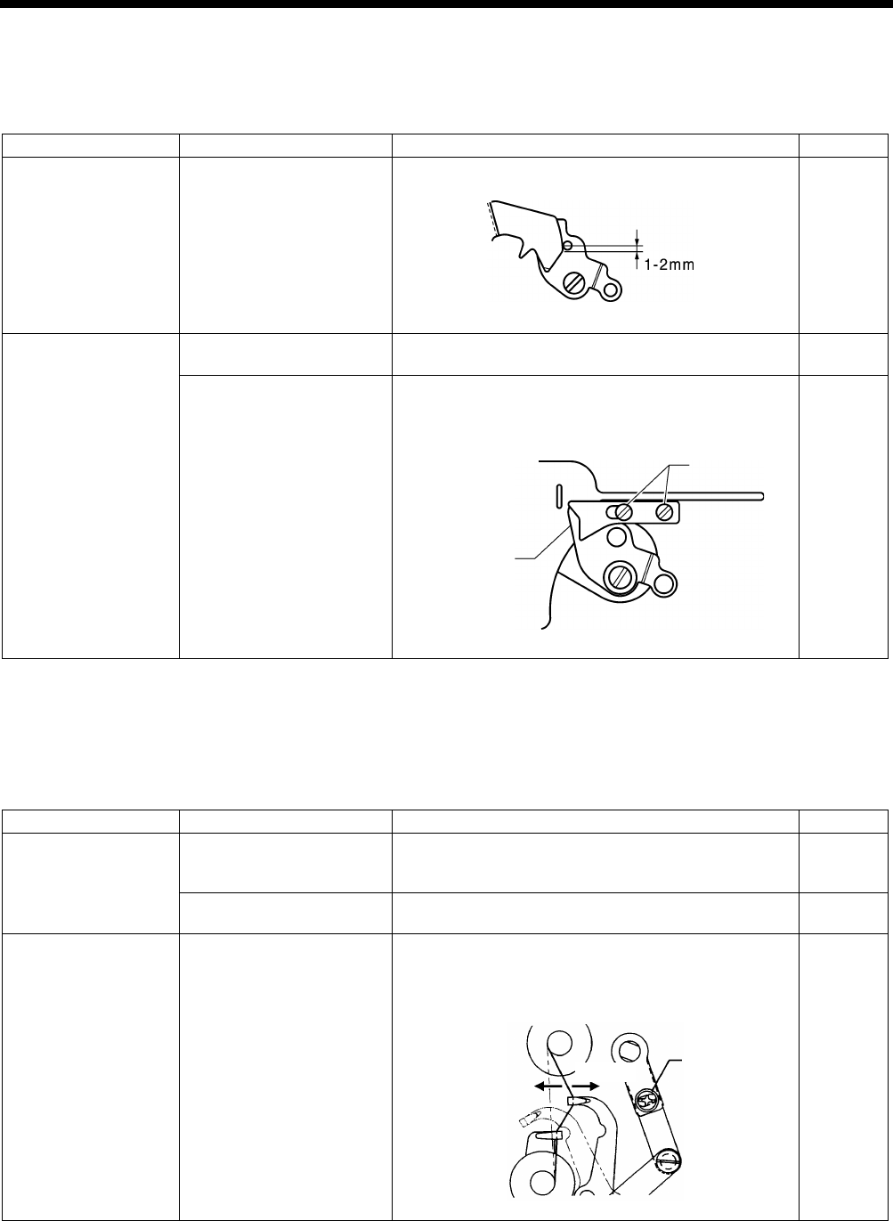
HE-800B
11. TROUBLESHOOTING
152
11-4. Uneven seams (2) …… Lower thread is lifted up at the sewing start
The end of the lower thread protrudes above the seam at the sewing start
Items with a “*” in the “Page” column should only be handled by a qualified technician.
Cause
Check
Remedy
Page
Lower thread retainer
Lower thread retaining
amount
Adjust the lower thread retaining amount.
104
Lower thread clamp
Lower thread clamp
opening timing
Adjust so that the lower thread clamp plate opens
when the feed mechanism moves 6 - 7 mm.
105
Lower thread clamping
force
・
If the lower thread clamp and lower thread presser
are bent, replace them.
・Check that the screws are tightened.
–
11-5. Uneven seams (3) ……Seam lifts up at the sewing start
Seam lifts up and does not tighten at the sewing start
Items with a “*” in the “Page” column should only be handled by a qualified technician.
Cause
Check
Remedy
Page
Upper thread trimmer
Upper thread trimmer
gradual opening timing
Adjust the timing so that the upper thread trimmer
gradually start opening when the feed mechanism
moves about 1.5 - 2.5 mm.
101
Upper thread trimmer
operation
Apply grease to the inclined face of the opening cam.
101
Upper thread feeding
Thread take-up amount
Loosen the screw to decrease thread take-up amount
so that upper thread does not pull out of trimmer
assembly at the sewing start.
109
4003Q
3999Q
Lower thread
clamp
Screw
4000Q
Screw
Increase
Decrease

HE-800B
11. TROUBLESHOOTING
153
11-6. Uneven seams (4) …… Uneven sewing pitch at the sewing start
Bird’s nests form at the sewing start, and after 5 - 6 mm the sewing pitch suddenly increases
Items with a “*” in the “Page” column should only be handled by a qualified technician.
Cause
Check
Remedy
Page
Lower thread clamp
Lower thread clamp
opening timing
Advance the timing at which the lower thread clamp
starts to open.
105
11-7. Uneven seams (5)……Poor rounding of seam
Items with a “*” in the “Page” column should only be handled by a qualified technician.
Cause
Check
Remedy
Page
Thread tension
Zigzag thread upper thread
tension
Adjust the upper thread tension appropriately.
INSTRUCTION
MANUAL CD
Zigzag tension disc
opening
・Check the opening of the zigzag tension discs.
・
Replace the tension release solenoid.
108
Lower thread tension
Adjust the lower thread tension appropriately.
INSTRUCTION
MANUAL CD
Threading Upper thread threading Thread the upper thread correctly. INSTRUCTION
MANUAL CD
Lower thread threading
Thread the lower thread correctly.
INSTRUCTION
MANUAL CD
Stitch patterns
Purl stitch, whip stitch
Set using parameter number 53.
INSTRUCTION
MANUAL CD
Tension release Tension release timing
Use parameter numbers 54 to 57 to set the timing for
changing the thread tension.
INSTRUCTION
MANUAL CD
11-8. Uneven seams (6) …… Around rear tack or front tack
Items with a “*” in the “Page” column should only be handled by a qualified technician.
Cause
Check
Remedy
Page
Tension release
Tension release timing
Use parameter numbers 54 to 57 to set the timing for
changing the thread tension.
INSTRUCTION
MANUAL CD
Threading
Upper thread threading
Thread the upper thread correctly.
INSTRUCTION
MANUAL CD
Lower thread threading Thread the lower thread correctly. INSTRUCTION
MANUAL CD
Zigzag thread tension
Zigzag tension disc
opening
・Adjust the tension disc opening amount.
・Check the opening of the zigzag tension discs.
・Replace the tension release solenoid.
108
Upper thread trimmer
Upper thread trimmer
operation
Apply grease to the inclined face of the opening cam.
101
11-9. Uneven seams (7) …… Loose thread end at end backtack
Cause
Check
Remedy
Page
Backtack shape
Checking the number of
end backtack stitches
Checking the end backtack
width
Adjust the setting values for parameter numbers 51
and 52. INSTRUCTION
MANUAL CD

HE-800B
11. TROUBLESHOOTING
154
11-10. Uneven seams (8) …… Thread sticking out at end backtack
Items with a “*” in the “Page” column should only be handled by a qualified technician.
Cause
Check
Remedy
Page
Backtack shape
Checking the number of
end backtack stitches
Checking the end backtack
width
Adjust the setting values for parameter numbers 51
and 52. INSTRUCTION
MANUAL CD
Uneven material
feeding
Work clamp pressure
Increase work clamp pressure.
* The
standard height of the adjustment screw is
approximately 30 mm, so tighten it further than this.
91
Work clamp
When using knit material, replace with the -3 work
clamp and needle plate.
–
Upper thread trimmer
opening timing
Adjust to an appropriate opening timing. 101
Upper thread trimmer
operation
Apply grease to the inclined face of the opening cam.
101
Lower thread clamp
opening timing
Adjust so that the lower thread clamp plate opens
when the feed mechanism moves 6 - 7 mm.
105
11-11. Uneven seams (9) …… Sticking in needle plate
Front and rear tack sections of material gets stuck in needle hole
Items with a “*” in the “Page” column should only be handled by a qualified technician.
Cause
Check
Remedy
Page
Start backtack
Number of start backtack
stitches
Use parameter number 38 to reduce the number of
stitches in the front tack.
*
If the material is soft, it can be effective to set the
number of stitches to 0.
INSTRUCTION
MANUAL CD
Rear tack
Rear tack vector shape
Use parameter number 31 to set the rear tack vector
shape to a rectangle.
* Setting the vector shape to a rectangle can be
effective when the width is less than the bar tack
width.
INSTRUCTION
MANUAL CD
Needle plate
Needle plate
・When using knit material, replace with the -3 needle
plate.
・
Replace with a needle plate with a smaller needle
hole.
–
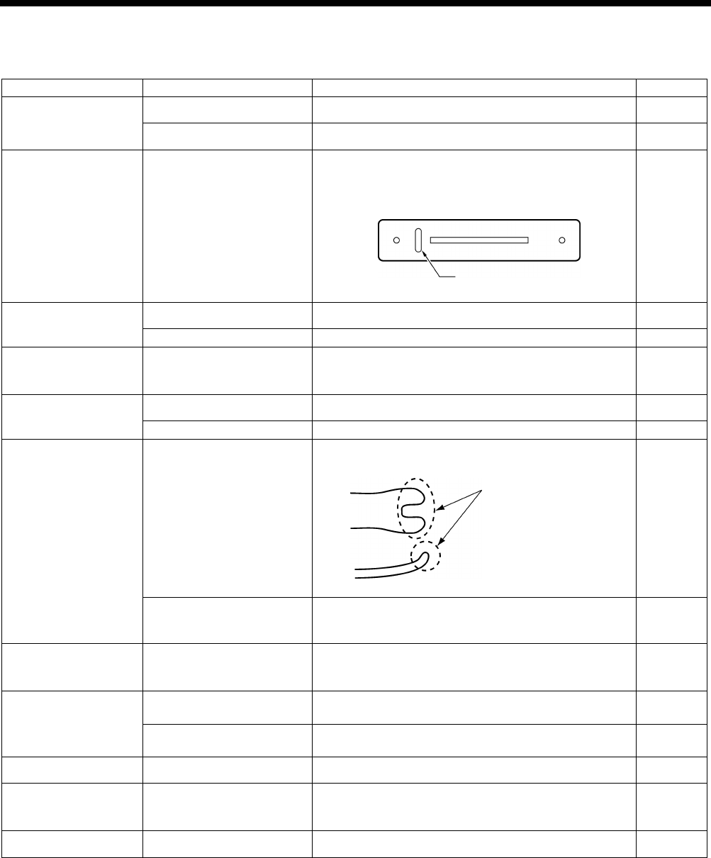
HE-800B
11. TROUBLESHOOTING
155
11-12. Uneven seams (10) …… All stitches
Items with a “*” in the “Page” column should only be handled by a qualified technician.
Cause
Check
Remedy
Page
Threading
Upper thread threading
Thread the upper thread correctly.
INSTRUCTION
MANUAL CD
Lower thread threading Thread the lower thread correctly. INSTRUCTION
MANUAL CD
Thread path
Flaw or abrasion on the
thread path
Polish with buff or replace the part.
Especially, pay attention to finishing around needle
plate hole.
–
Needle
Needle installation
Insert needle fully into needle bar.
INSTRUCTION
MANUAL CD
Needle size
Replace needle with thicker one.
–
Thread chips or dust
Rotary hook rim
Rotary hook edge
Around needle plate hole
Remove thread chips or dust.
–
Upper thread
Upper thread tension
Increase upper thread tension while checking stitches.
INSTRUCTION
MANUAL CD
Thread and needle
Replace needle with one that fits for the thread.
–
Rotary hook holder
Flaw on the rotary hook
holder
Polish with buff or replace the part.
91
Rotary hook holder and
inner rotary hook overlap
amount
Adjust the rotary hook holder and inner rotary hook
overlap amount. 91
Rotary hook Rotary hook lubrication Decrease the quantity of lubrication oil.
*
Note that if you reduce the amount of oil too much,
thread breakages may occur.
109
Bobbin winder tension
bracket
Bobbin thread tension
Use the tension nut to adjust the lower thread winding
tension.
–
Uneven bobbin winding
Move bobbin winder tension bracket up and down to
adjust.
INSTRUCTION
MANUAL CD
Lower thread
Lower thread tension
Adjust the lower thread tension.
INSTRUCTION
MANUAL CD
Bobbin case
Damaged outside of
bobbin case and bent
bobbin holder spring, etc.
Polish with buff or replace the part.
* Use the HE-800B bobbin case. –
Stitch patterns Purl stitch, whip stitch Set using parameter number 53. INSTRUCTION
MANUAL CD
3996Q
3997Q
Needle plate hole
Adjust the rotary hook
overlap amount.
Check flaw here
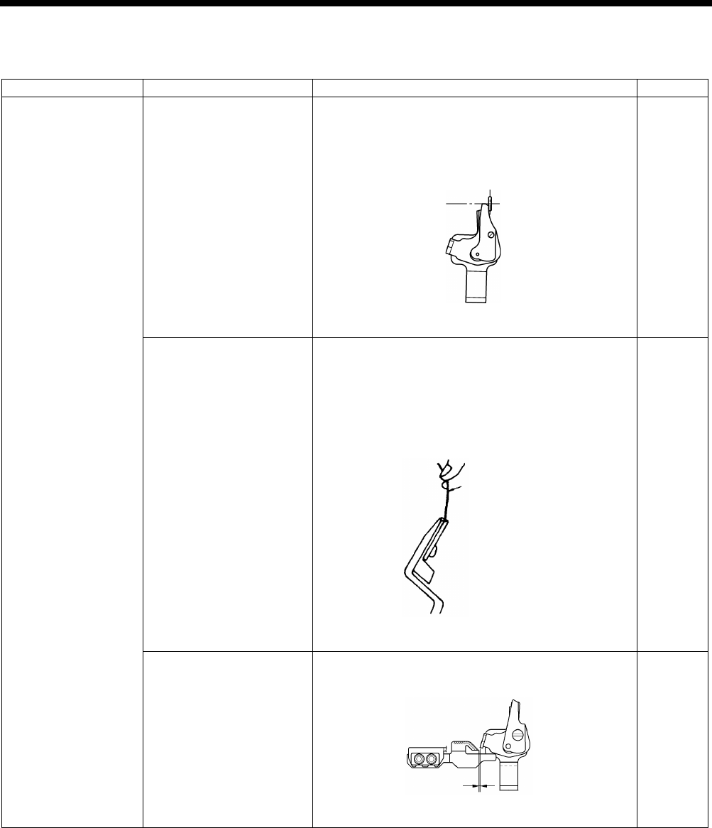
HE-800B
11. TROUBLESHOOTING
156
11-13. Upper thread run out
Items with a “*” in the “Page” column should only be handled by a qualified technician.
Cause
Check
Remedy
Page
Upper thread trimmer
assembly
Installation position of
upper thread trimmer
assembly
Adjust the installation position of upper thread trimmer
assembly by moving the setting plate assembly.
・
Upper thread trimmer longitudinal position
adjustment
・Upper thread trimmer cutting depth adjustment
98, 99
Upper thread trimmer
assembly holding force
Adjust so that the thread does not come out when you
cut it with trimmer and hold the end of the thread
between your fingers and gently swing the assembly.
・Bend the trimmer U or replace them so that the
correct force is applied.
・Repair any damage from striking the needle.
–
Opening cam position
Adjust the position so that the trimmer does not touch
the opening cam when the work clamp is lowered.
101
(Continued on next page)
4006Q
4005Q
4107M
Approx. 0.5 mm
Cotton yarn #60
Holding force approx. 2N
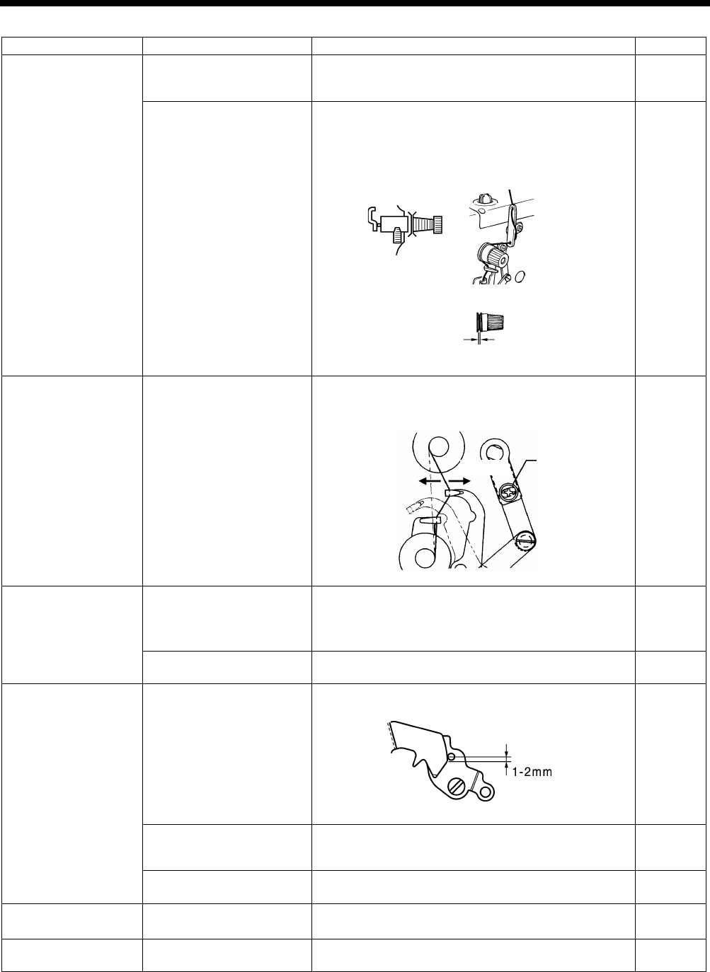
HE-800B
11. TROUBLESHOOTING
157
Cause
Check
Remedy
Page
Tension release
timing
End of tension release at
the beginning of sewing
Use parameter number 54 to retard the timing for
changing the thread tension (increase the setting
value).
INSTRUCTION
MANUAL CD
Opening amount of zigzag
tension discs and bar tack
tension discs
・ Adjust the zigzag tension
discs by moving the
tension stud bracket in and out.
・ Adjust the bar tack tension discs opening amount to
0.5 - 1.0 mm by removing the top cover and moving
the tension release cam.
108
Upper thread feeding
Thread take-up amount
Loosen the screw to decrease thread take-up amount
so that upper thread does not pull out of trimmer
assembly at the sewing start.
109
Rotary hook
Needle bar height and
needle bar lift amount
(The gauge is an option
part.)
1. Adjust the needle bar height to “1” on the gauge.
2.
Adjust the needle and rotary hook timing to “2” on
the gauge.
88
89
Thread chips on rotary
hook edge
Remove thread chips.
–
Lower thread
Lower thread retaining
amount
Adjust the lower thread retaining amount.
104
Lower thread snapping
Adjust the positions of the lower thread retainer, lower
thread clamp and lower thread presser plate so that
they do not snap the lower thread.
INSTRUCTION
MANUAL CD
Lower thread clamp
opening timing
Adjust so that the lower thread clamp plate opens
when the feed mechanism moves 6 - 7 mm.
105
Sewing start speed
Slow start
Use parameter numbers 10 to 13 to set the number of
stitches and the speed for slow starting. INSTRUCTION
MANUAL CD
Bar tack thread
tension
Bar tack thread tension is
too strong.
Make the bar tack tension as weak as possible.
INSTRUCTION
MANUAL CD
4008Q
4000Q
Screw
Increase
Decrease
4003Q
Tack tension
0.5 - 1 mm
Zigzag tension
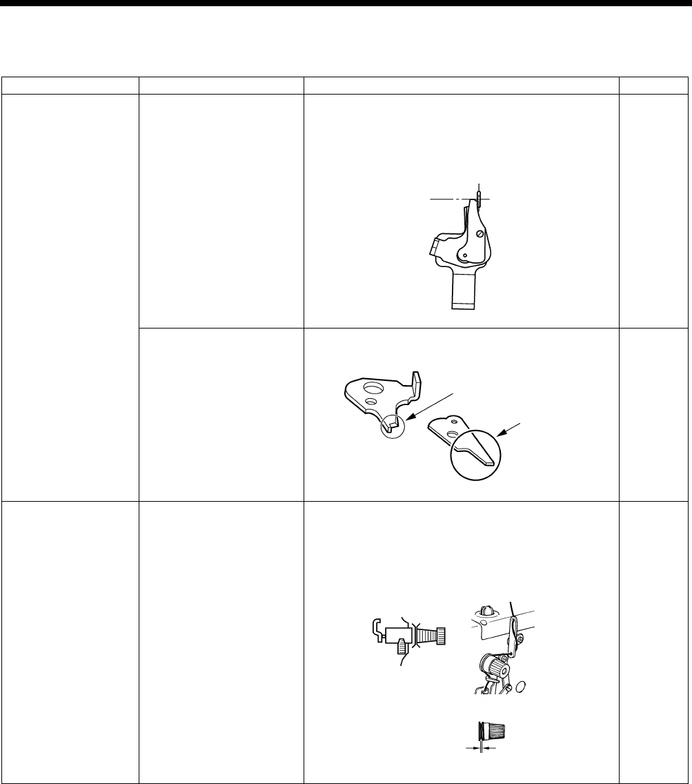
HE-800B
11. TROUBLESHOOTING
158
11-14. Unraveling of thread trimmed by upper thread trimmer assembly
Items with a “*” in the “Page” column should only be handled by a qualified technician.
Cause
Check
Remedy
Page
Upper thread trimmer
assembly
Installation position of
upper thread trimmer
assembly
Adjust the installation position of upper thread trimmer
assembly by moving the setting plate assembly.
・
Upper thread trimmer longitudinal position
adjustment
・ Upper thread trimmer cutting depth adjustment
98, 99
Burr on tips of upper thread
trimmer M and upper
thread trimmer U.
Polish with buff or replace the part.
–
Tension release
timing
Opening amount of zigzag
tension discs and bar tack
tension discs (particularly
zigzag tension discs)
・ Adjust the zigzag tension discs by
moving the
tension stud bracket in and out.
・ Adjust the bar tack tension discs opening amount to
0.5 - 1.0 mm by removing the top cover and moving
the tension release cam.
108
4009Q
4005Q
Check burr on upper
side here
Check burr here
4008Q
Tack tension
0.5 - 1 mm
Zigzag tension
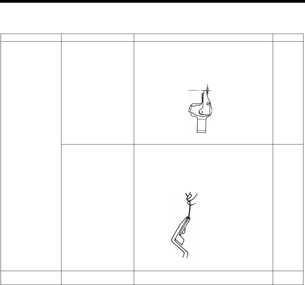
HE-800B
11. TROUBLESHOOTING
159
11-15. Upper thread miss-trimming
Items with a “*” in the “Page” column should only be handled by a qualified technician.
Cause
Check
Remedy
Page
Upper thread trimmer
assembly
Installation position of
upper thread trimmer
assembly
Adjust the installation position of upper thread trimmer
assembly by moving the setting plate assembly.
・
Upper thread trimmer longitudinal position
adjustment
・Upper thread trimmer cutting depth adjustment
98, 99
Upper thread trimmer
assembly holding force
Adjust so that the thread does not come out when you
cut it with trimmer and hold the end of the thread
between your fingers and gently swing the assembly.
・
Bend the trimmer U or replace them so that the
correct force is applied.
・Repair any damage from striking the needle.
–
Trimmer driving arm
Upper thread trimmer
cutting depth
Adjust the position of the trimmer driving arm roller.
99
4006Q
4005Q
Cotton yarn #60
Holding force approx. 2N
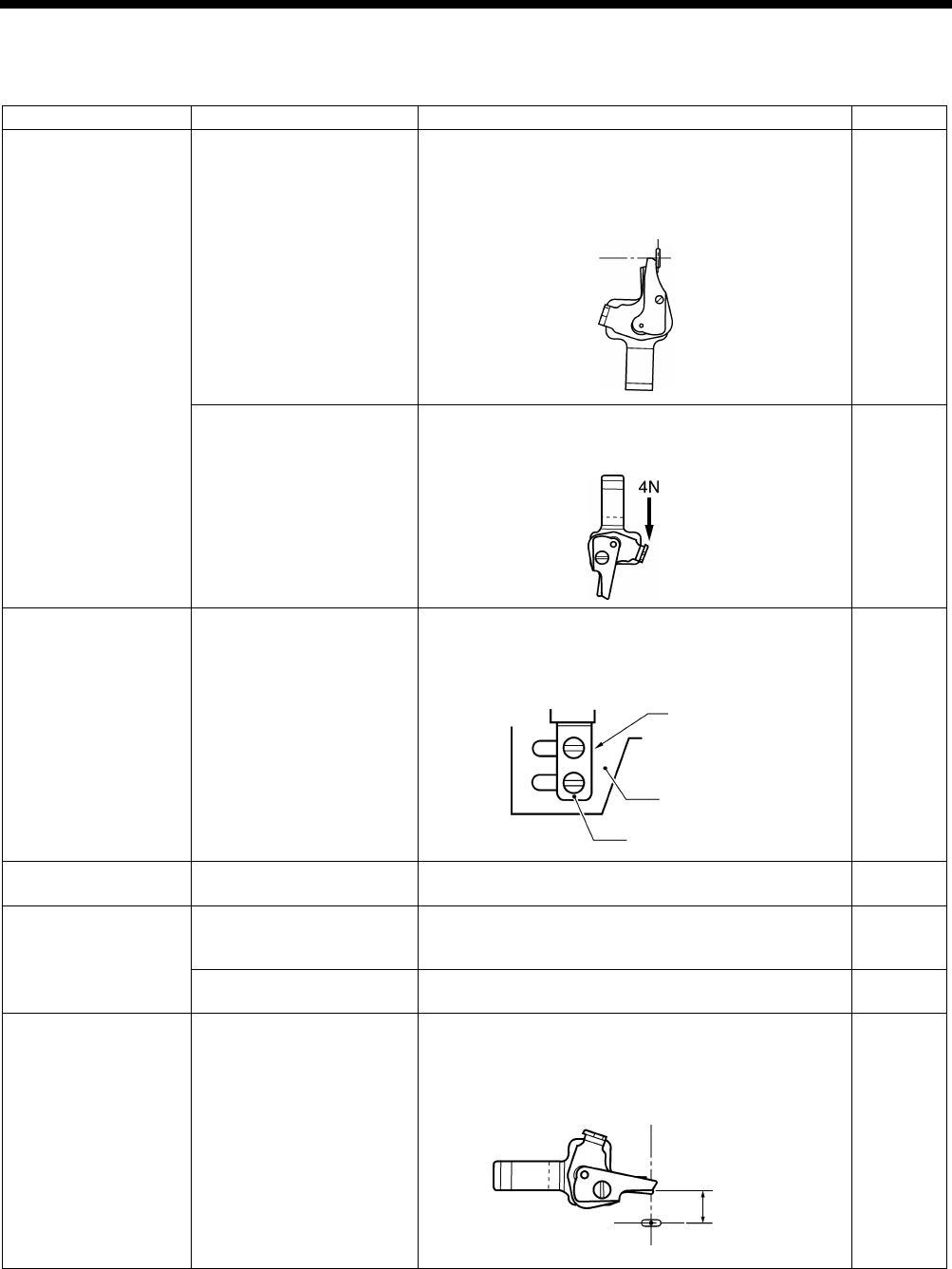
HE-800B
11. TROUBLESHOOTING
160
11-16. Needle strikes upper thread trimmer
Items with a “*” in the “Page” column should only be handled by a qualified technician.
Cause
Check
Remedy
Page
Upper thread trimmer
assembly
Installation position of
upper thread trimmer
assembly
Adjust the installation position of upper thread trimmer
assembly by moving the setting plate assembly.
・
Upper thread trimmer longitudinal position
adjustment
・Upper thread trimmer cutting depth adjustment
98, 99
U
pper thread trimmer
operating force
Remove any scratches and burrs, and adjust the upper
thread trimmer M to open when the projection is
pressed with a force of 4N or less.
–
Longitudinal feed arm
Installation position of the
longitudinal feed arm
Move the upper thread trimmer driving link so that it
stops at the face plate. In this position, tighten the bolts
so that the small slot in the upper thread trimmer lever
and the edge of the washer are aligned.
97
Cam
Upper thread trimmer
opening timing
Adjust so that the cam opens the stop plate properly. 102
Opening cam
Upper thread trimmer
gradual opening timing
Adjust the timing so that the upper thread trimmer
gradually start opening when the feed mechanism
moves about 1.5 - 2.5 mm.
101
Upper thread trimmer
operation
Apply grease to the inclined face of the opening cam.
101
Work clamp home
position
Work clamp home position
position
After the home position has been detected, press the
THREAD key to lower the work clamp, and then adjust
the distance between the upper thread trimmer and the
center of the needle to 5.5 - 6.0 mm.
–
(Continued on next page)
4005Q
4011Q
4012Q
Aligned
Upper thread
trimmer lever
Washer
5.5 - 6.0 mm
4010Q
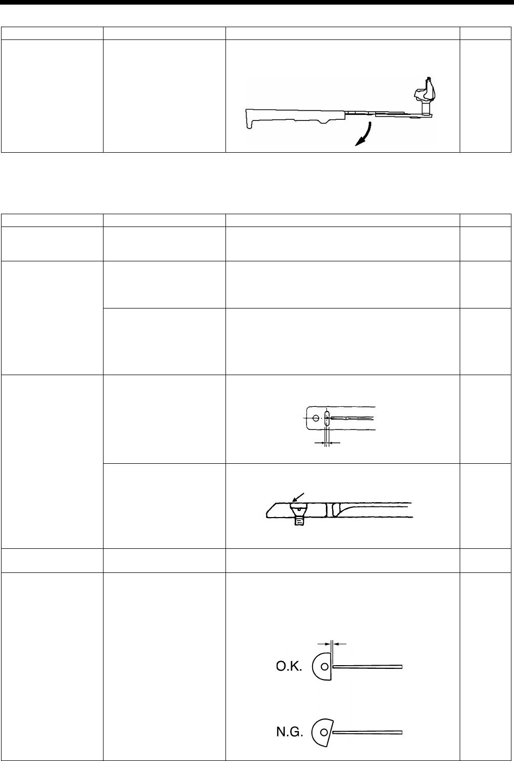
HE-800B
11. TROUBLESHOOTING
161
Cause
Check
Remedy
Page
Upper thread trimmer
lever
Upper thread trimmer lever
operating force
Adjust so that the upper thread trimmer lever opens
gently when the stop plate is separated from the
stopper.
–
11-17. Needle breakage
Items with a “*” in the “Page” column should only be handled by a qualified technician.
Cause
Check
Remedy
Page
Needle
Needle installation
As viewed from the direction of the face plate, attach
the needle so that the groove of the needle faces
frontward.
91
Rotary hook
Needle bar height and
needle bar lift amount
(The gauge is an option
part.)
1. Adjust the needle bar height to “1” on the gauge.
2.
Adjust the needle and rotary hook timing to “2” on
the gauge.
–
89
Gap between the needle
and the tip of the rotary
hook
Adjust the gap between the needle and the rotary hook
tip to 0.01 - 0.08 mm. (Adjust to as large as possible
without causing skipped stitches to occur.)
*
Move the needle bar to the left and right with your
finger, and check that the tip of the rotary hook does
not strike the needle.
91
Needle plate
Needle plate position
Adjust the forward/back position of the needle plate so
that the needle is in the center of the needle hole.
–
Burr on the screw hole
edge (in event
of uneven
material feeding)
Polish with buff.
–
Upper thread trimmer
assembly
Needle strikes upper
thread trimmer
Refer to “11-16. Needle strikes upper thread trimmer”.
160, 161
Cutter
Clearance between needle
bar and cutter
Install the cutter so that the clearance between the
needle bar and the cutter is 0.3 mm.
*
The cutter release section of the needle bar should
be at a right angle to the cutter.
88
4013Q
4015Q
Bisect
4014Q
4016Q
0.3 mm
(Needle plate cross section)
Check the chamfered side
finishing
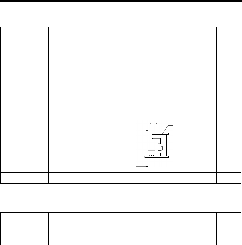
HE-800B
11. TROUBLESHOOTING
162
11-18. Imperfect cutter function (imperfect material cutting)
Items with a “*” in the “Page” column should only be handled by a qualified technician.
Cause
Check
Remedy
Page
Cutter
Installation position of
cutter
Install the cutter so that its edge is aligned with the top
of the needle plate.
95
Cutter blade
・ If blade is worn or chipped, sharpen it or replace it.
・
Replace with the special needle plate (optional).
INSTRUCTION
MANUAL CD
Damage to cutter
mechanism parts
Loose screws
・Replace any parts that are damaged.
・Tighten any loose screws. –
Cutter solenoid
Check for a disconnected
cord.
Check that cutter sensor connector P7 on the main
P.C. board and cutter solenoid connector P2 on the
cutter P.C. board are properly connected.
INSTRUCTION
MANUAL CD
Solenoid stopper
Nut
Check if the nut is loose, and tighten it securely.
–
Cutter sensor position
・Adjust the cutter sensor position.
・
Check if the mounting screws are loose, and tighten
them securely.
66
Cutter bar guide
Smoothness of cutter
operation
Adjust the cutter bar guide so that the cutter operates
smoothly with no play.
64
11-19. Cutter does not return
Items with a “*” in the “Page” column should only be handled by a qualified technician.
Cause
Check
Remedy
Page
Cutter
Cutter blade
If blade is worn or chipped, sharpen it or replace it.
–
Sticks in material Needle plate Replace with the special needle plate (optional). INSTRUCTION
MANUAL CD
Cutter bar guide
Smoothness of cutter
operation
Adjust the cutter bar guide so that the cutter operates
smoothly with no play.
64
4017Q
Cutter sensor
4.5 ± 0.5 mm
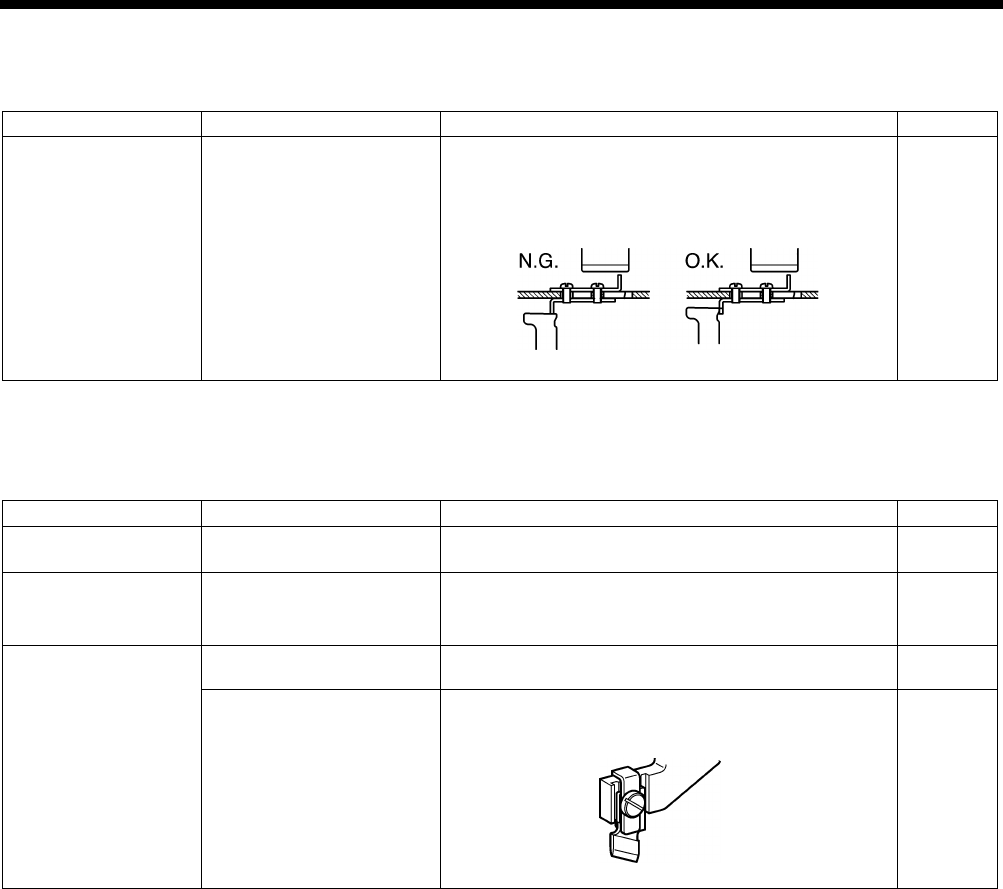
HE-800B
11. TROUBLESHOOTING
163
11-20. Cutter and upper thread trimmer touch
Items with a “*” in the “Page” column should only be handled by a qualified technician.
Cause
Check
Remedy
Page
Upper thread trimmer
Check if the cam opens the
stop plate.
Adjust the cam position.
*
If the feed mechanism operates when the cam has
not opened the stop plate, the cutter will bump
against the upper thread trimmer.
102
11-21. Seam is cut
Items with a “*” in the “Page” column should only be handled by a qualified technician.
Cause
Check
Remedy
Page
Setting the length of
the hole
Length of the hole
Set parameter number 02 to the same value as the
length of the cutter being used.
INSTRUCTION
MANUAL CD
Setting the cutter
spacing
Cutting of zigzag seam
・Use parameter number 04 to set the cutter X space.
・Use parameter number 03 to set the correction of the
cutter X position.
INSTRUCTION
MANUAL CD
Cutter
Cutter play
Adjust the cutter bar guide so that the cutter operates
smoothly with no play.
64
Cutter knife bending
Use the cutter holder (option) to prevent the cutter
knife from becoming bent.
95
4018Q
4019Q
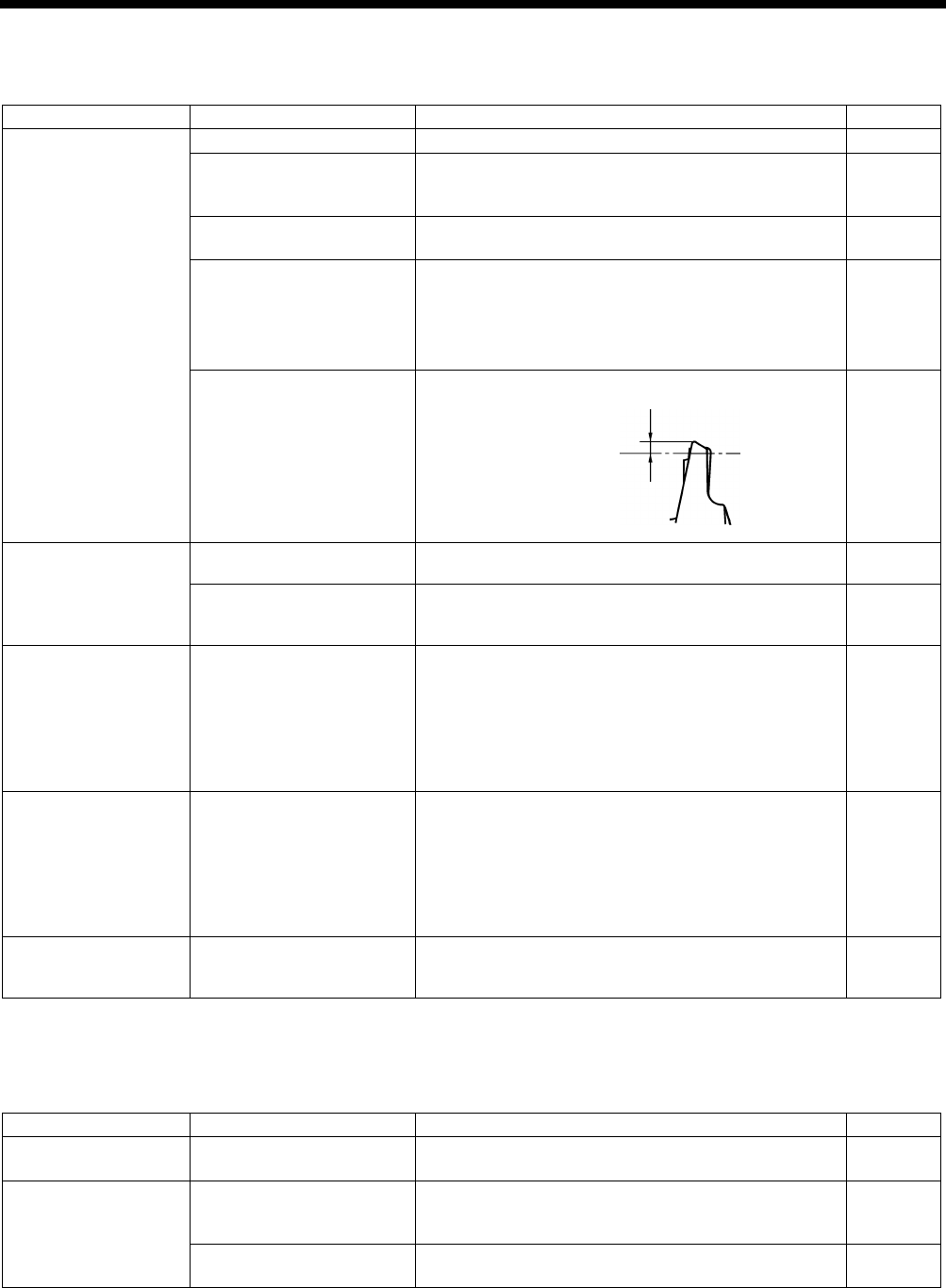
HE-800B
11. TROUBLESHOOTING
164
11-22. Upper thread miss-winding
Items with a “*” in the “Page” column should only be handled by a qualified technician.
Cause
Check
Remedy
Page
Upper thread trimmer
Installation height
Adjust the upper thread trimmer installation height.
100
Upper thread trimmer
gradual opening timing
Adjust the timing so that the upper thread trimmer
gradually start opening when the
feed mechanism
moves about 1.5 - 2.5 mm.
101
Upper thread trimmer
opening timing
Adjust so that the cam opens the stop plate properly.
102
Upper thread trimmer
assembly movement
・
Polish blade of upper thread trimmer M and upper
thread guide with buffer.
・
Check for burrs on the top surface of upper thread
trimmer M.
・Replace the parts.
–
Lateral position of upper
thread trimmer
Adjust the lateral position of the upper thread trimmer.
98
Stitch quality
Upper thread tension
Decrease tension to such a degree that it does not
influence stitch quality.
INSTRUCTION
MANUAL CD
Zigzag width in the zigzag
stitch portion
Use parameter number 08 to increase the zigzag width
to such a degree that it does not influence the seam
shape.
INSTRUCTION
MANUAL CD
Work clamp
Uneven material feeding
・
Increase work clamp pressure. (Press material so
that the material is properly stretched.)
・
When using knits or woven materials, replace the
parts with the -3 specification parts:
Length feed plate (for specification -
3), work clamp
assembly (for knits), needle plate 1.2 (for
specification -3)
–
Underlay Underlay is being sewn. ・
Use parameter number 47 to reduce the underlay
feed pitch to about 0.5.
・Use parameter number 14
to reduce the underlay
sewing speed.
*
If sewing knitted wear, problems may easily occur
with the insertion of the upper thread, so you may
need to process the end of the thread.
INSTRUCTION
MANUAL CD
Bar tack
Straight bar tacking is
being carried out
When carrying out straight bar tacking, problems may
easily occur with the insertion of the upper thread, so
you will need to process the end of the thread.
–
11-23. Work clamp is not raised (1) ……Error does not occur.
Items with a “*” in the “Page” column should only be handled by a qualified technician.
Cause
Check
Remedy
Page
Work clamp lifting
height
Check the wo
rk clamp
lifting height setting
Change the settings of memory switch Nos. 001, 002,
003, 004.
INSTRUCTION
MANUAL CD
Work clamp motor
Cord connection
Check if there are any problems with the connection
and contacts of work clamp motor connector P23 on
the main P.C. board.
INSTRUCTION
MANUAL CD
Work clamp motor drive
gear
Check if the drive gear screw is loose.
59
4020Q
Approx. 1 mm
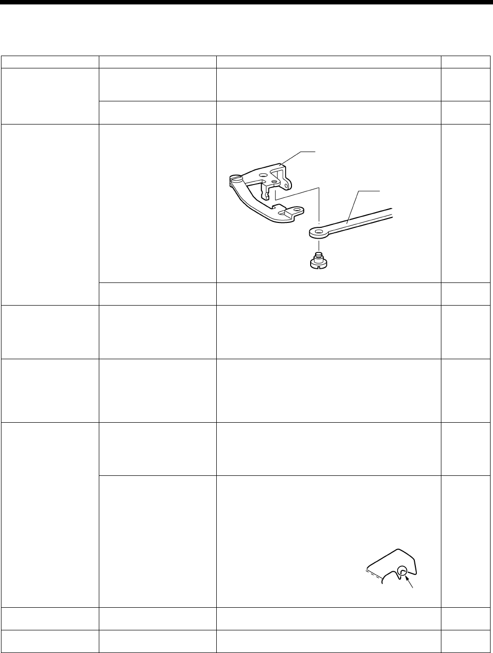
HE-800B
11. TROUBLESHOOTING
165
11-24. Work clamp is not raised (2) ……Error occurs.
Items with a “*” in the “Page” column should only be handled by a qualified technician.
Cause
Check
Remedy
Page
Upper thread trimmer
Interference between
upper thread trimmer and
work clamp
Adjust the installation height of the upper thread
trimmer (remove the upper thread trimmer and check).
* Be particularly careful when sewing joints.
100
Upper thread trimmer
operation
Apply grease to the inclined face of the opening cam. 101
Lower thread trimmer
Interference between fixed
knife set, lower thread
clamp, lower thread
pr
esser and lower thread
retainer.
Repair or replace the parts.
–
Rubbish, dust or thread
scraps present
Remove all rubbish, dust and thread scraps from the
lower thread trimmer.
–
Loose screws
Check for loose screws in
the upper thread trimmer,
lower thread trimmer and
work clamp lifter
mechanisms.
Securely tighten all screws.
–
Work clamp lifting
height setting
Check the work clamp
lifting height setting.
Change the settings of memory switch Nos. 001, 002,
003, 004.
*
If the work clamp lifting height is too high, the lower
thread trimming operation and the work clamp lifting
will become stiff, and the work clamp motor may go
out of step.
INSTRUCTION
MANUAL CD
Threading
Lower thread threading
Insert the bobbin correctly and pass the lower thread
through the bobbin case correctly.
* If the bobbin is inserted back-to-
front, it will spin
loosely and the work clamp motor may go out of
step.
INSTRUCTION
MANUAL CD
Lower thread tension
・ Reduce the lower thread tension.
*
If the lower thread tension is much too strong, the
work clamp motor may go out of step.
・ Use memory switch No. 060
to reduce the work
clamp lifting speed setting to make the lifting speed
slower.
・ Buff this section A to reduce the
thread retaining resistance.
INSTRUCTION
MANUAL CD
*
*
Upper thread trimmer
Upper thread trimmer
operation
Carry out opening timing adjustment for the upper
thread trimmer.
101
Presser lifter home
position
Presser lifter home position
Adjust the presser lifter home position.
87
4022Q
Remove the shoulder
screw to check.
Lower thread
trimmer link A assembly
Lower thread
trimmer
connecting rod
4023Q
A
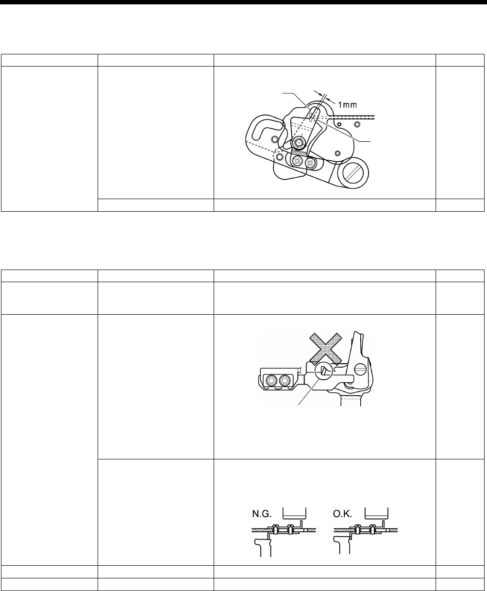
HE-800B
11. TROUBLESHOOTING
166
11-25. Lower thread is not trimmed (pulls when material is removed)
Items with a “*” in the “Page” column should only be handled by a qualified technician.
Cause
Check
Remedy
Page
Fixed knife set
Fixed knife and movable
knife do not mesh.
Adjust the fixed knife set installation position.
104
Knife tip is bent or chipped.
Repair or replace the knife.
–
11-26. Feed mechanism does not move and error occurs.
Items with a “*” in the “Page” column should only be handled by a qualified technician.
Cause
Check
Remedy
Page
Feed motor
Cord connection
Check if there are any problems with the connection
and contacts of feed motor connector P22 on the main
P.C. board.
INSTRUCTION
MANUAL CD
Upper thread trimmer
Upper thread trimmer
position
Remove and re-install the upper thread trimmer.
101
Check if the cam opens the
stop plate.
Adjust the cam position.
*
If the feed mechanism operates when the cam has
not opened the stop plate, the cutter will bump
against the upper thread trimmer.
102
Feed home position
Feed home position
Adjust the feed home position.
86
Feed timing belt
Feed timing belt tension
Adjust the feed timing belt.
54
4024Q
Fixed knife
Movable knife
Install so that the projection on
trimmer M is
not inserted.
* Always make sure that the upper
thread trimmer is in the correct
position before use.
4018Q
4895M
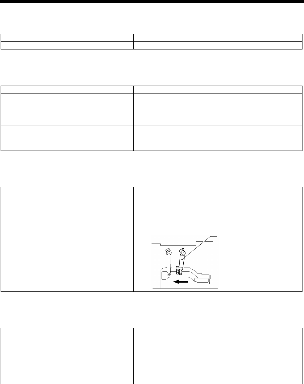
HE-800B
11. TROUBLESHOOTING
167
11-27. Needle does not zigzag or noise occurs when needle zigzags
Items with a “*” in the “Page” column should only be handled by a qualified technician.
Cause
Check
Remedy
Page
Stopper
Stopper position
Adjust the stopper position.
75
11-28. Sewing machine stops during sewing
Items with a “*” in the “Page” column should only be handled by a qualified technician.
Cause
Check
Remedy
Page
Thread breakage
detector
Thread
breakage detector
position
Adjust the thread breakage detector position.
*
If the detector is not adjusted, sewing may stop even
when the thread is not broken.
107
Threading
Upper thread threading
Pass the thread correctly through the thread guide.
INSTRUCTION
MANUAL CD
Error [E301]
Upper thread trimmer
operation
Move the work clamp up and down and check that it
moves smoothly.
21
Uneven stitches
Adjust to obtain the optimum stitches.
INSTRUCTION
MANUAL CD
11-29. Upper shaft does not rotate as far as the needle up stop position
Items with a “*” in the “Page” column should only be handled by a qualified technician.
Cause
Check
Remedy
Page
Thread retainer and
rotary hook are
touching.
Thread trimmer
mechanism position
1. Turn the machine pulley backward to set the
needle bar to the needle up position.
2.
Push the thread driving arm in the direction of the
arrow to set the thread trimming mechanism to the
home position.
–
11-30. Operation panel display freezes and operation is not possible
Items with a “*” in the “Page” column should only be handled by a qualified technician.
Cause
Check
Remedy
Page
Poor connection
inside control box.
P.C. board cord connections
・ Check if there
are any problems with the
connection and contacts of connector P5 on the
main P.C. board.
・
Check if there are any problems with the
connection and contacts of connector P2 and
operation panel connector P3 on the motor P.C.
board.
INSTRUCTION
MANUAL CD
4109M
Thread driving arm

MEMO
168
HE-800B
SERVICE MANUAL
© 2014 Brother Industries, Ltd. All Rights Reserved.
HE-800B
I3061003
D
2014.03. D (1
)
