ACE&EASTMAN Highlead Gc24688 Instructions & Parts Catalog User Manual
2016-09-26
User Manual: ACE&EASTMAN Highlead Gc24688 Instructions & Parts Catalog
Open the PDF directly: View PDF ![]() .
.
Page Count: 64

Parts Catalog
SHANGHAI HUIGONG NO.3 SEWING MACHINE FACTORY
GC24688Series
1-/2-Needle Post-Bed Compound-feed Lockstitch Industrial
Sewing Machine
Instruction Manual
-----Abstract-----
1. PRECAUTION BEFORE STARTING OPERATION ·································································· 1
1) Safety precaution ······················································································································· 1
2) Precaution before starting operation ··························································································· 1
3) Precaution for operating conditions ···························································································· 1
2. SPECIFICATIONS······················································································································ 1
3. PREPARATION BEFORE STARTING TO OPERATE ································································ 2
1) Connection of control box ········································································································· 2
2) Connection of pneumatic parts ·································································································· 2
3) Oil pan ······································································································································ 3
4) Operation panel ························································································································· 4
5) Adjusting the needle stop position ····························································································· 4
4. HOW TO USE THE MACHINE ································································································· 5
1) Threading ······························································································································ 5
2) Adjusting of the thread regulator ······························································································ 5
3) Adjusting of upper thread tension ·························································································· 5
4) Winding the lower thread ········································································································· 6
5) Threading the lower thread ······································································································ 6
6) Adjusting the lower thread tension ··························································································· 6
7) Installing the needle ················································································································· 7
8) Alternating presser foot movement amout ················································································ 7
9) Adjusting the presser foot pressure ·························································································· 7
10) Adjusting the stitch length ······································································································· 8
11) Using the manual switches ······································································································· 8
12) Cleaning ································································································································ 9
13) Lubrication ······························································································································ 9
14) Adjusting the trailing length after thread trimming ································································· 10
15) Back tacking ·························································································································· 10
16) Adjusting the feed dog ··········································································································· 10
17) Adjusting the needle bar height ······························································································ 11
18) Adjusting the gap between the needle and the rotary hook tip ················································· 12
19) Adjusting of the needle and the hook timing ········································································· 12
20) Hook protection ····················································································································· 13
21) Adjusting the needle and feed mechanism timing ··································································· 13
22) Bobbin case lifter ·················································································································· 14
23) Adjusting the presser foot height ···························································································· 15
24) Adjusting the alternating presser foot movement amout ························································· 15
25) Adjusting the presser foot timing ························································································· 16
26) Driving knife adjustment ······································································································· 17
27) Adjusting the thread trimming timing ···················································································· 17
28) Adjusting the fixed knife position and bobbin thread clamping ··············································· 18
29) Safety clutch ·························································································································· 19
PARTS CATALOG ··························································································································· 20

— 1 —
1. PRECAUTIONS BEFORE STARTING OPERATION
1) Safety precautions
(1) When turning the power on, keep your hands and fingers away from the area around/under the needle
and the area around the pulley.
(2) Power must be turned off when the machine is not used, or when the operator leaves his/her seat.
(3) The power must be turned off before tilting the machine head, installing or adjusting the machine, or
when replacing.
(4) Avoid placing fingers, hairs, bars etc. nears the pulley, bobbin winder pulley, when the machine is
operation. Injury could result.
(5) Do not insert fingers into the thread take-up cover, under/round the needle, or pulley when the
machine is in operation.
(6) If mini motor cover, finger guard, and/or eye guard are installed, do not operate the machine without
these safety devices.
2) Precaution before starting operation
(1) If the machine's oil pan has an oil sump, never operate the machine before filling it.
(2) If the machine is lubricated by a drop oiler, never operate the machine before lubricating.
(3) When a new sewing machine is first turned on, verify the rotational direction of the pulley with the
power on. (The pulley should rotate counterclockwise when viewed from the pulley.)
(4) Verify the voltage and (single or three) phase with those given on the machine nameplate.
3) Precaution for Operating Conditions
(1) Avoid using the machine at abnormally high temperature (35℃ or higher) or low temperatures (5℃
or lower). Otherwise, machine failure may result.
(2) Avoid using the machine in dusty conditions. Avoid using the machine in areas where too much
electrical noise, resulted from the high-frequency welder and others is generated
2. SPECIFICATIONS
Item GC24688-2-D GC24688-1LD GC24688-1RD
Max. Speed 2400rpm
Stitch length 0 to 9mm
Needle bar stroke 34mm
Presser foot
clearance
By hand 9 mm
By knee 16 mm
Rotating hook Large vertical hook (1.6 times)
Needle DP×17 #18-#25
Presser foot alternation 1-7mm
Needle gauge (mm) 8(Standard),10,12 ───
Auto presser foot lifter Pneumatic
Oil lubrication method Automatic lubrication
Motor 750W sevor motor
— 2 —
3. PREPARATION BEFORE STARTING TO OPERATE
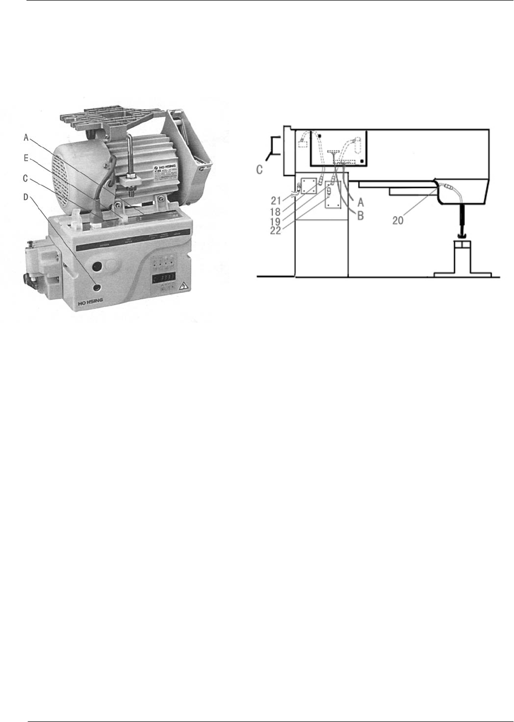
1) Connection of control box
If the machine which customer bought is not wholly assembled, the customer should connection the
electrical wires and the air pipes by themselves. Shows as the Fig.1 and Fig.2
Fig. 1 Fig. 2
There are same connectors which need to connect to the machine from the control box:
A: machine function input , connect to the PCB board on the machine arm.
B: pass the valve signal from the PCB board to the magnet valve board.
C: needle position monitor input ,connect to the monitor on the machine arm.
D: operation panel input ,connect to the panel.
E: operation pedal input, connect to the pedal.
If there is any problems during connecting wires, please check the instruction book of HO HSING control box.
NOTICE: all the connects is unique with each other ,and if they can’t match it ,please check whether you get the
right one.
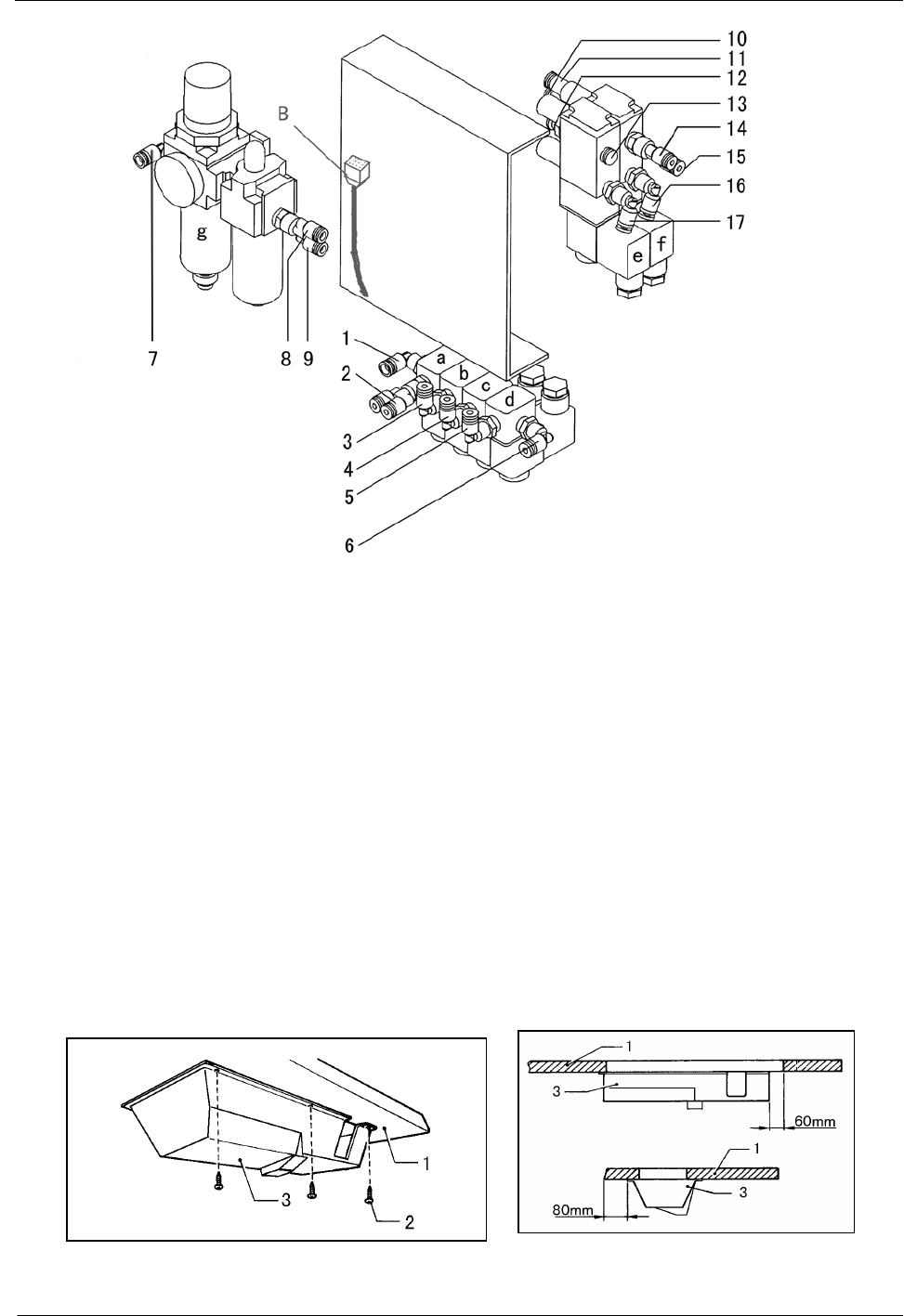
2)Connection of pneumatic parts
The pneumatic parts of the machine are controled by the magenet valves which assembled on the setting
board, and the position where the setting board be assembled under the machine table should be decided by the
length of the wires and the air pipes.
The pneumatic parts are composed by the filter g ,the solenoid valves a~f and the cylinders they control
The method of pneumatic parts connecting have been showed by Fig.3:
— 3 —
Fig.3
Here are the functions of the solenoid valves:
a: thread cutting b: thread tension c: press foot alternation d: material guider(just for double needle)
e: back tacking f: press foot lift
The pressed air come from air compressor go to the input join 7,after be filtered,the output 8 and 9 link to
the inputs of the solenoid valves as follow:
1:connect to 8,pressed air input 2:link to the cylinder of thread cutting (bidirectional)
3:link to the cylinder of thread tension 4:link to the cylinder of press foot alternation
5:link to the cylinder of material guider 6:connect to the joint 14 as the input of material guider
10:connect to 9 as input for press foot lift 11:connect to 12 as the input of back tacking.
13:plug 15&16:link to the cylinder of press foot lift (bidirectional)
17:link to the cylinder of back tacking
When connecting the air pipes, please check the instruction mark of the solenoid joints at the setting board.
3) Oil pan
Fig.4 Fig.5
— 4 —
The installation of the oil pan is showed as the fig.4 and fig.5:
(1) Install the oil pan 3 to the underside of the worktable 1 in the place shown in the illustration using the
nails 2.
(2) From front view, the oil pan 3 to the side
is 60mm; from right view, the oil pan 3 to the side
is 80mm.
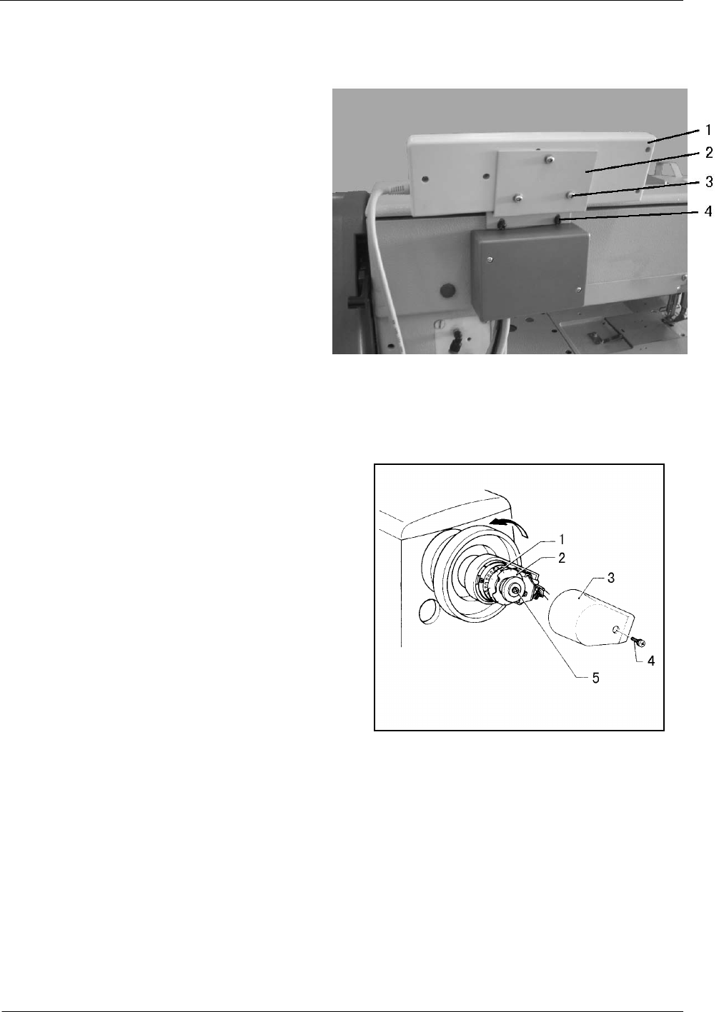
4) Operation panel
Installe the operation panel As Fig.6 shows :
(1) Install the operation panel 1 to the set
plate 2 with the three screws 3. Fig.6
(2) Install the set plate 2 to the back of the machine arm with the two screws 4.
5) Adjusting the needle stop position
(1) Adjusting the needle up stop position
When the sewing machine stops in the needle up stop
position (the stop position of trimming) and the treadle is
pressed back, the red mark on the pulley should be
consistent with the mark on the belt cover A. Adjust as
follows by Fig.7:
a. Turn off the power switch.
b. Loosen the screw 4, and then remove the cover 3.
c. When the red mark stops in a position over the
mark on the belt cover, the needle up stop position disc 1
should be turned in the opposite direction as the direction Fig.7
of machine pulley rotation. When the red mark stops in a position under the mark on the belt cover, Turn the
disc 1 in the same direction as the pulley rotation direction.
(2) Adjusting the needle down stop position
When the sewing machine stops in the needle down stop position, the black mark on the pulley should be
consistent with the mark on the belt cover A. Adjust as follows:
a. Turn off the power switch.
b. When the black mark stops in a position over the mark on the belt cover, the needle down stop position
disc 2 should be turned in the opposite direction as the direction of machine pulley rotation. When the black
— 5 —
mark stops in a position under the mark on the belt cover, Turn the disc 2 in the same direction as the pulley
rotation direction.
c. After adjusting, install the cover 3, with screw 4.
Note: There is no need to loose the screw 5, when turning the discs.
4. HOW TO USE THE MACHINE
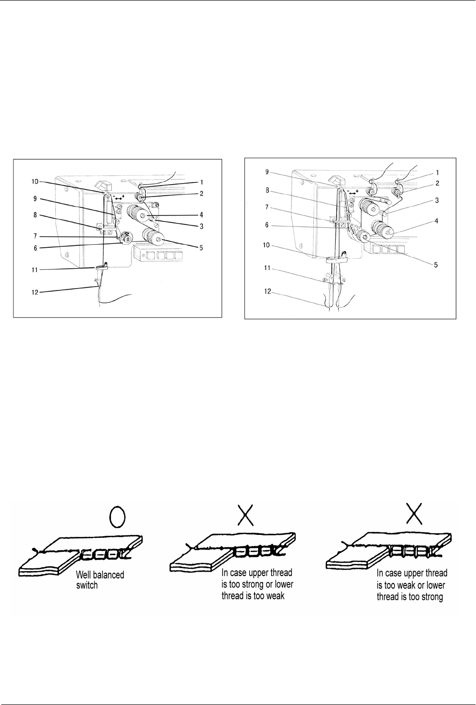
1) Threading
Raise the thread take-up lever to its highest position and pass the upper thread in the following order.
Fig.8 Fig.9
2) Adjusting of the thread regulator
The thread regulator 9 of Fig.8 ( 8 of Fig 9)regulates the amount of needle thread necessary for stitch
formation. The setting depends on the following factors: material thickness, yarn characterisation and stitch
length.
The thread regulator is fitted with slots for this purpose. Moving in the “+”direction increases the quantity
of needle thread; Moving in the “-”direction reduces the quantity of needle thread.
3) Adjusting of upper thread tension
Fig.10
The thread tension should be as low as possible. The crossover point should be in the center of the material.
Upper thread tension can be adjusted by thread tension nut 4 and 5 (see Fig.8 and Fig.9). Turn the thread tension
nut clockwise to increase the needle thread tension. Turn the thread tension nut counter-clockwise to decrease
the needle thread tension.
— 6 —
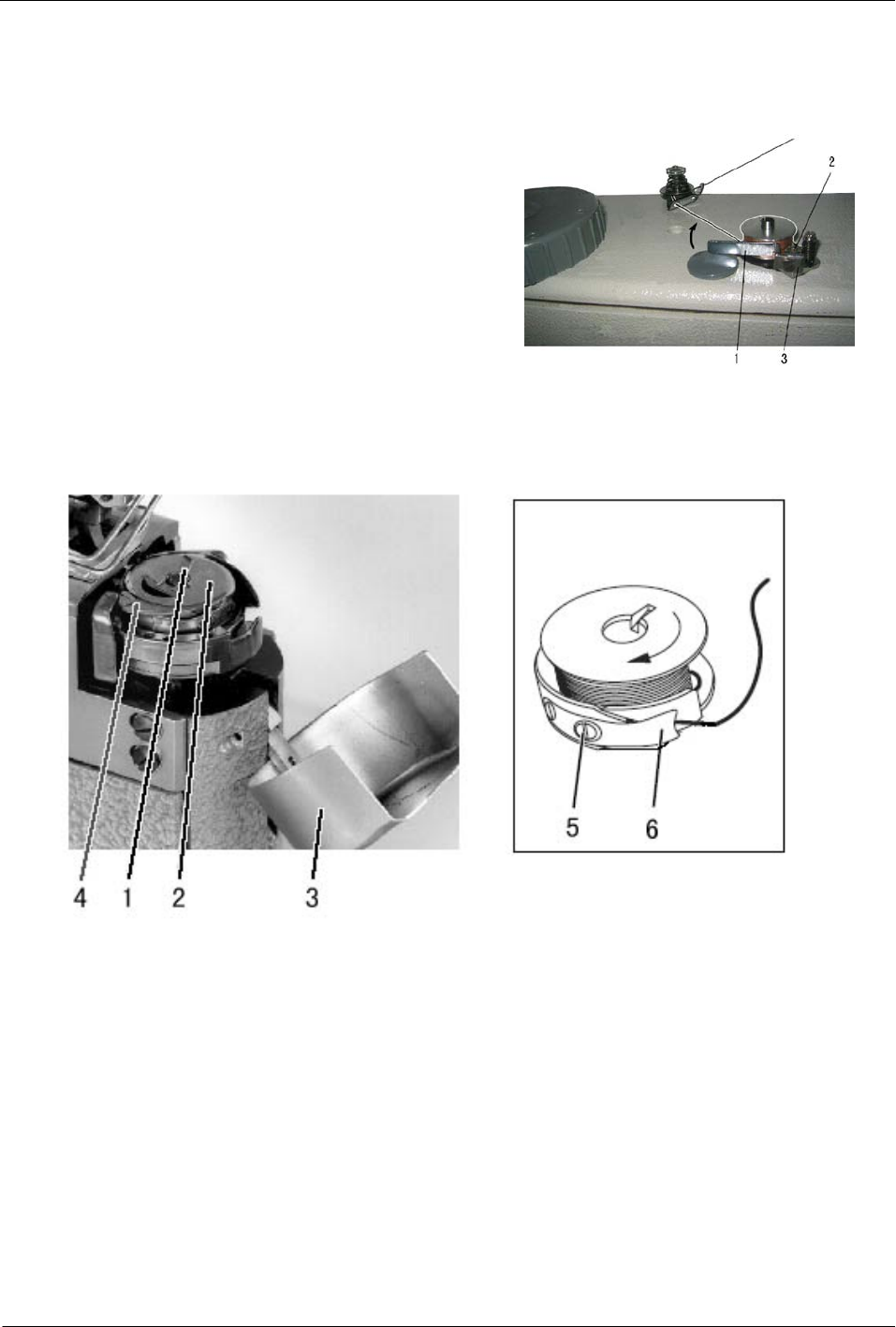
4) Winding the lower thread
Winding the lower thread as Fig.11 shows :
(1) Place the bobbin on the bobbin winder shaft.
(2) Pass the thread for winding thread as shown, and wind
the end of the thread clockwise around the bobbin several
times.
(3) Push the bobbin presser 1 toward the bobbin.
(4) The operation will automatically stop when winding is
completed. The amount of thread wound onto the bobbin
should be at 80% of the maximum bobbin capacity.
(5) After the thread has been wound on, remove the bobbin
and cut the thread with the thread-trimming knife
Fig.11
5) Threading the lower thread
Fig.12
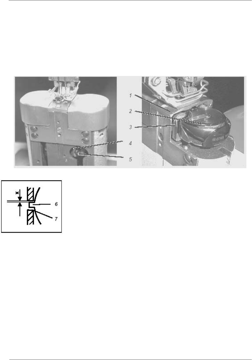
(1) Removing the empty looper-thread bobbin, be showed on Fig.12
Raise the setting foot, open shuttle cover 3 ,then ,raise bobbin-housing flap 1 and remove upper part of
bobbin-housing 2.So,you can remove empty looper-thread bobbin.
(2) Threading looper thread
Full bobbin 4 in the upper part of bobbin-housing 2 (When the thread is unwound the bobbin must rotate in
the opposite direction (see arrow),then ,drew looper thread through slit 5 beneath tensioning spring 6.
6) Adjusting the lower-thread tension
Open the shuttle cover first and adjust the tensioning spring 6 with regulating screw 5.If want to increase
looper-thread tension, turn screw 5 clockwise and if want to decrease looper-thread tension, please turn screw 5
counter clockwise. After the adjustment ,close the shuttle cover.
— 7 —
Caution: The looper-thread tension may only be adjusted with the sewing machine switched off.
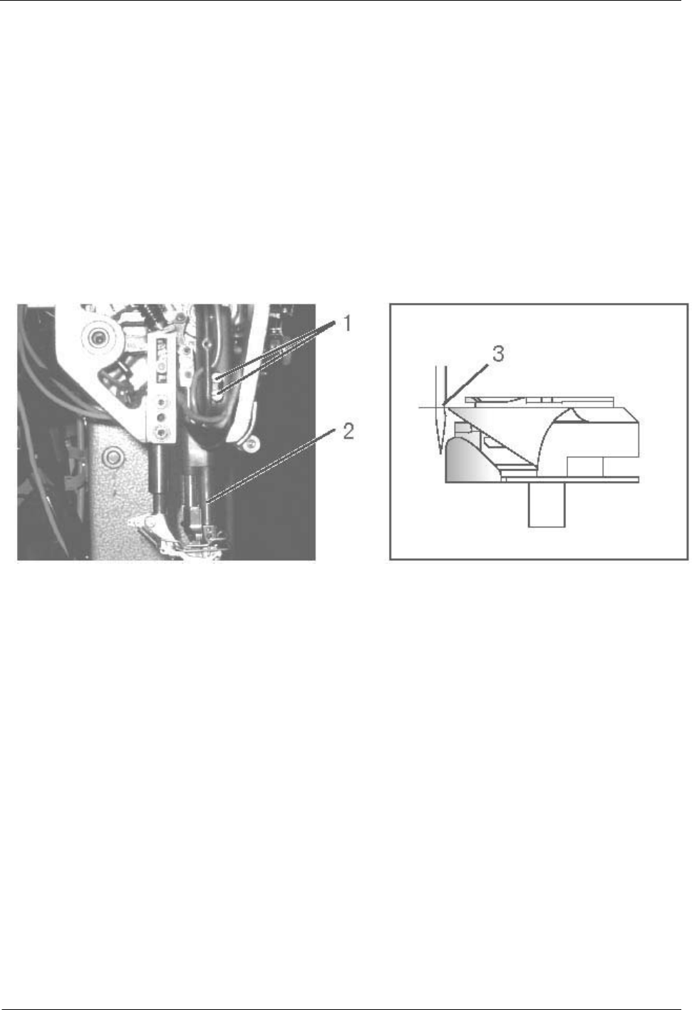
7) Installing the needle
Note: Before attach needle, be sure to turn off the power.
As showed on Fig.13
1) Turn the balance wheel by hand to raise the needle bar
1 to its highest position;
2) Loosen the needle clamping screw 3;
3) Hold the needles with the long groove face to the
bobbin case of the same side , and insert it as deeply as it
will go into the needle clamping holes.
4) Tighten the needle clamping screw3.
Fig.13
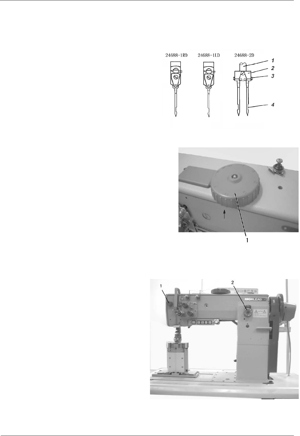
8) Alternating presser foot movement amount
The alternating movement amount for the inner presser foot
and the outer presser foot can be adjusted within the range of 1-7
mm using the alternating presser foot movement dial 1. Turn the
alternating presser foot movement dial 1 clockwise or
counterclockwise to align the mark. (MIN. A, B, C, D, E, F
MAX. ) When the alternating movement change from MIN to
MAX, the sewing speed will turn form 2000 rpm to 1700 rpm
synchronously. Fig.14
9) Adjusting the presser foot pressure
Look at Fig.15,
The presser foot pressure should be set as weak as
possible, but strong enough so that the material can’t
slip out. If the presser-adjusting dial 1 is turned
clockwise, the presser foot pressure will become
stronger, and if it is turned counterclockwise, the
pressure will become weaker.
Fig.15
— 8 —
10) Adjusting the stitch length
The feed adjustment dials 2 can be used to set stitch length. (See Fig.15) The sewing machine will switch
between the two stitch lengths each time the stitch length change switch is pressed.
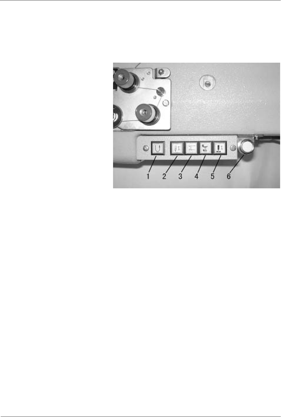
11) Using the manual switches
Be showed by Fig.16:
(1) Quick reverse switch
Back tacking is carried out during
sewing only while the switch 1 is
being pressed.
(2) Needle up or down switch
If the switch 2 is pressed, The
needle will move up to the needle up
stop position from down stop
position or move down to the needle
down stop position from up stop
position.
(3) Auto back tacking select switch Fig.16
If the switch 3 is pressed when either start back tacking or end back tacking has been set to ON at the
operation panel, back tacking is canceled for the first time only. Furthermore, if the switch 3 is pressed
when neither starting nor end back tacking has been set, back tacking is carried out for the first time only.
(4) Alternating presser foot movement change switch
The sewing machine can be switched between two different alternating presser foot movement amounts
each time when the switch 4 is pressed.
(5) Presser foot guider
The switch controls the cylinder of the presser foot guider and the status changed by each press of the
buttom. OFF: Presser foot guider turn off; ON: Presser foot guider on.
(6) Stitch counter switch
The orange light on the switch will flash and the machine will stop when the bobbin thread is used up.
Push the switch one more time after change the bobbin. The sewing machine cannot run before the switch
be pushed one more time. The stitch count should be set according to the stitch length and the count of the
bobbin thread. (it is special order parts)
Notice: the switch is not work until the correlative functions of the control box are set. The functions please read
the parameter 42, 43, 44 in the servo motor user manual.
— 9 —
12) Cleaning
(1) The area around the feed dog and the hook should be cleaned every day.
(2) Remove any thread scraps from inside the rotary hook.
(3) Keep the control box clean.
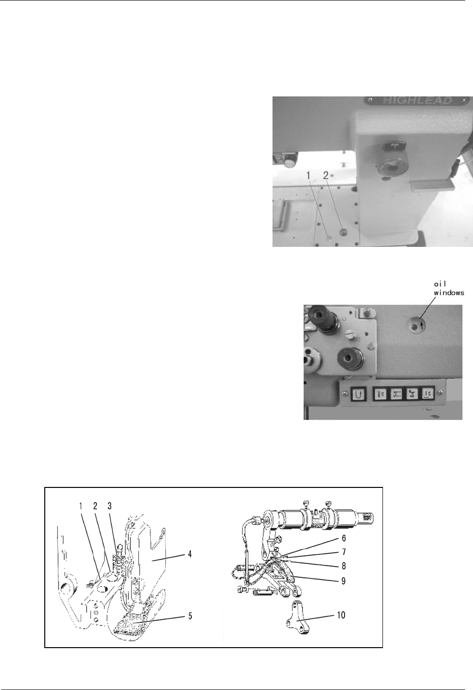
13) Lubrication
(1) Check the oil level at the sight glass 2 of Fig.17 every
week. If the oil is not enough, remove oil-filling screw 1
and pour in oil. Check oil level at sight glass 2. The oil
level must be between “EMPTY” and “FULL”. Replace
oil-filling screw 1. After running for 500 hours since
buying the new sewing machine, the oil must be changed.
Then change the oil every two years.
Fig.17
(2) Lubricating wicks and felt (see the Fig.19)
a. The wick 1 leading from the oil sump to the oscillating crank 4
must be fixed between the groove 2 in the arm and the spring 3
of the recirculation wick.
b. When the oil satchel is changed, the flock side should be faced
to connecting plate 10. The oil wick 7 and 8 should be set
between the oil satchel 9 and plate 8.
(3) Checking the lubrication oil Fig.18
Turn on the power switch. Depress the treadle gently and check that the oil level rises in the oil sight glass.
Fig.19
— 10 —
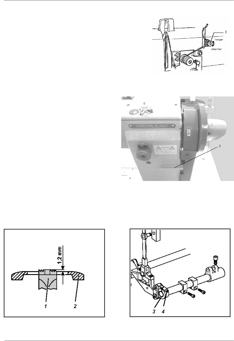
14) Adjusting the trailing length after thread trimming
Look at Fig.20: adjust by turning the pre-tensioner . If the tension of
the pre-tension is increased, the lengths of the threads trailing
from the needle tips will be reduced; if the tension is reduced, the
lengths will be increased.
Fig.20
15) Back tacking
When the reverse lever 1 or the quick reverse
switch is pressed during sewing, the feed direction
will be reversed. When it is released, the feed
direction will return to normal.(Fig.21)
Fig.21
16) Adjusting the feed dog
Fig.22
— 11 —
Caution: Check and adjust height of the feed-dog only when sewing machine is switched off.
The checking and correction are showed by Fig.22
(1)Standard checking
The highest position of feed-dog 1 must be 1.2mm(approx. one tooth depth) above the throat plate level.
Set stitch length”0”(Turn button counter-clockwise as far as it will go).Then, turn handwheel until feed-dog 1
has reached its highest position, check the height of feed-dog 1 above throat plate level 2
(2)Correction
Set stitch length “0”,loosen clamping screw 4 at crank 3, and twist crank 3 in such a way that the highest
position of feed-dog 1 is 1.2mm above throat plate 2,then tighten clamping screw 4 at last.
Attention: crank 3 must not be shifted axially when being turned.
Fig.23
17) Adjusting the needle bar height
Be showed by Fig.23:
In looping stroke position the hook tip must be at the level of the middle of the needle hollow groove 3 .
When the position is not correct ,follow the step below :
(1) Remove the face plate.
(2) Set the feed adjustment dials to “0”.
(3) Turn the pulley to set the needle bar 2 to its lowest position.
(4) Loosen the screw 1 and then move the needle bar 2 up and down to adjust so that the hook tip is at the
level of the middle of the needle.
(5) Tighten the screw 1, install the face plate.
— 12 —
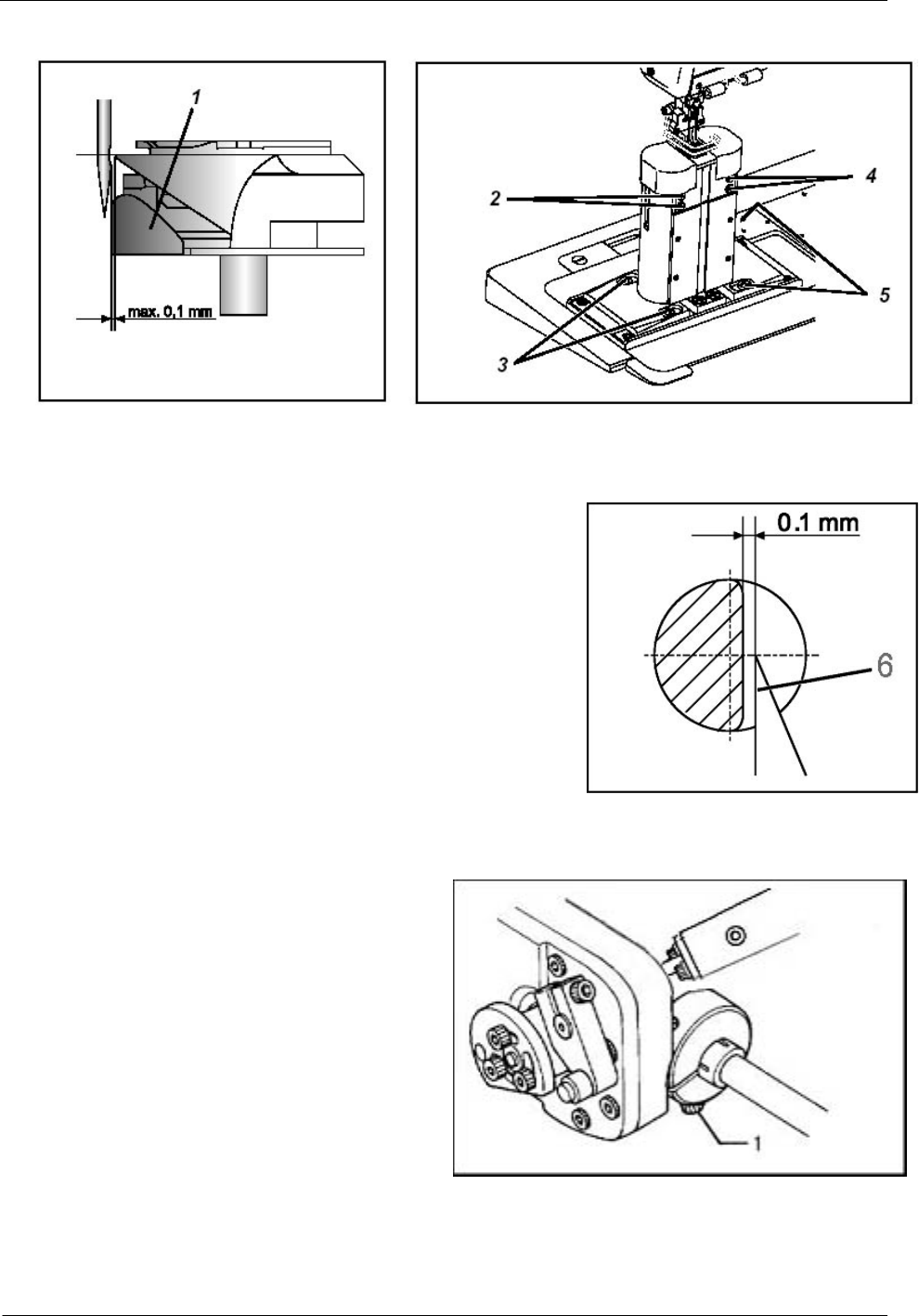
18) Adjusting the gap between the needle and the rotary hook tip
Fig.24
Look at Fig.24 and Fig.25:
The gap between the needle and the rotary hook tip 6 is 0.1 mm.
check the position of the hook tip and the needle hollow groove ,if the
position is not correct with the requirement ,adjust it as follow:
(1) Loosen the screws 2 (for left hook) screw 4(for right hook) of the
throat plate.
(2) Loosen fastening screw 3(for left hook), fastening screw 5(for
right hook) of the hook support.
(3) Shift hook support correspondingly.
(4) Tighten the screws 3,5 and 2,4. Fig.25
19) Adjusting of the needle and the hook timing
Look at Fig.26
(1) Set the stitch length to “0”.
(2) Open the shuttle cover.
(3) Overturn the arm.
(4) Loosen the screw 1
(5) Turn the machine pulley to raise the needle bar
from its low position to the point that the needle rises
2.4 mm.
(6) Turn the rotary hook to align the rotary hook tip
with the center of the needle. Fig.26
(7) Tighten the screw 1.
— 13 —
20) Hook protection
Fig.27
Be showed by Fig.27,in looping stroke position the needle must abut on the hook protection 1 without
being displaced.Move needle in looping stroke position by pulley. In looping stroke position the hook tip 4 is at
the level of the middle of the needle. Press needle against hook protection 1 manually. The needle should not
touch the hook tip.the hook protection 1 chould be adjusted by screw 3.
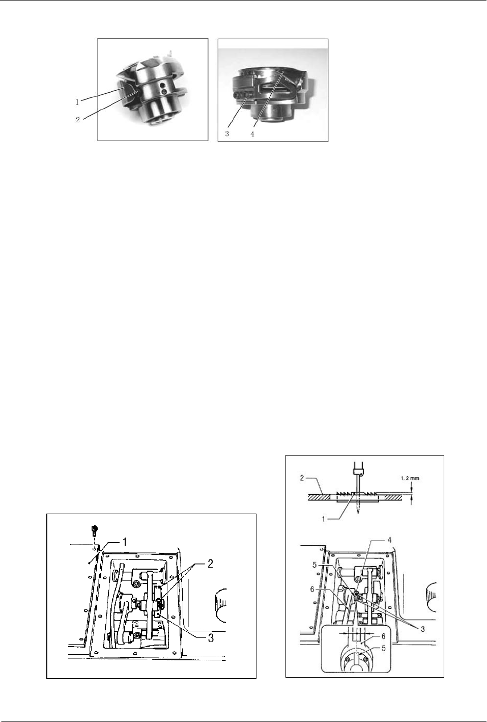
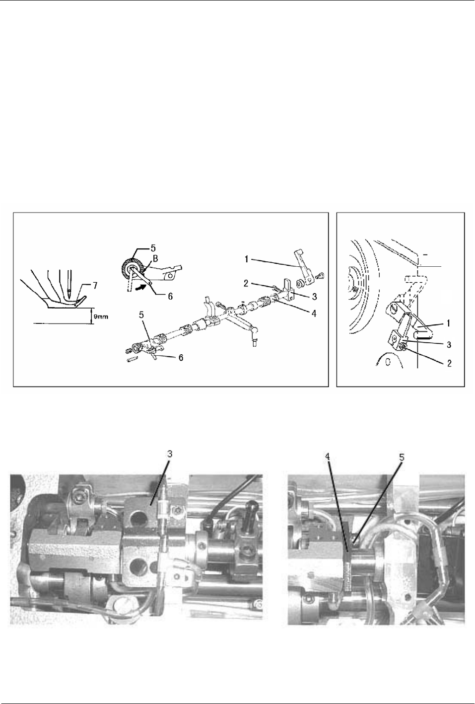
21) Adjusting the needle and feed mechanism timing
(1) Horizontal feed direction (showed by Fig.28)
Set the feed adjustment dials to the maximum settings. Then turn the machine pulley until the bobbin tip
catches the thread (when the needle is 2.4mm above the lowest position) The needle and the feed dog do not
move even when the reverse lever is moved up and down at this time.
a. Remove the bed upper cover 1.
b. Set the feed adjustment dial to the maximum settings.
c. Loosen the two screws 2.
d. Turn the machine pulley until the needle is at its thread catching position.
e. Turn the lower feed cam 3 gradually until it is at the position where the needle and the feed dog do not
move even when the reverse lever is moved up and down.
f. Tighten the two screws 2.
(2) Vertical feed direction(showed by Fig.29)
Fig.28 Fig.29
— 14 —
Set the feed adjustment dials to the minimum settings. Then adjust as follows so that the feed dog 1 is at its
highest position (1.2mm above the top of the needle plate 2) when the needle bar is at its lowest position.
a. Loosen the two screws 3
b. Turn the machine pulley to set the needle bar to its lowest position.
c. Turn feed cam 4 to align the point 5 of feed cam 4 with the centerline of feed rod 6
d. Tighten the screws 3
22) Bobbin case lifter
Fig.30
Look at Fig.30 and Fig.31, the thread lever must pull the needle thread over the
bobbin case through gap 7 of the throat plate1.
At the moment of the thread slipping through lifting finger 3 lifts bobbin case
2.Due to the unhindered thread passage the desired seam pattern is achieved with the
lowest possible thread tension.
The lifting finger 3 is controlled via the eccentric in the hook shaft and the control
Fig.31 block 4.
Wrong adjustments may cause thread breakage, loops at the bottom side of the material and loud noise.
Checking: Lifting finger 3 must lift bobbin case 2 in such a way that the thread can slip laterally between bobbin
case lug 6 and the gap of the throat plate without being hindered.
When bobbin case 2 is lifted ,the distance X between holding lug 6 and the gap of the throat plate must
correspond to the thickness of the sewing thread. Sew some stitches manually, then check the distance x at the
moment of the bobbin case lifting.
Adjustment: Screw off cover of the hook support, loosen clamping screw 5 at the control block 4,then,twist
lifting finger 3 in such a way that the clearance in the lifting finger remains small. At last, tighten clamping
screw 5 and screw on cover of the hook support.
If the lifting course is too small, it will no unhindered thread passage, if the lifting course is too small, it
will cause loud noise and the bobbin case 5 will flung against the other side of the throat plate gap 7.
— 15 —
23) Adjusting the presser foot height(Fig.32)
The standard height of the outer presser foot 7 is 9 mm when it is raised by the presser lifter bar 1.
(1) Remove the belt cover.
(2) Loosen the presser adjusting screw, to release the presser foot pressure.
(3) Raise the presser lifters bar 1 and then loosen the screw 3.
(4) Move the outer presser bar up or down to adjust so that the height of the outer presser foot 7 is 9 mm.
(5) While the stopper pin 6 is touching against the notch B in the presser foot lifter connection 5 and while
pushing the presser lifter shaft so that there is no play in the thrust direction, tighten the screw 2.
(6) Turn the presser adjusting screw to adjust the presser foot pressure.
(7) Install the belt guards.
Fig.32
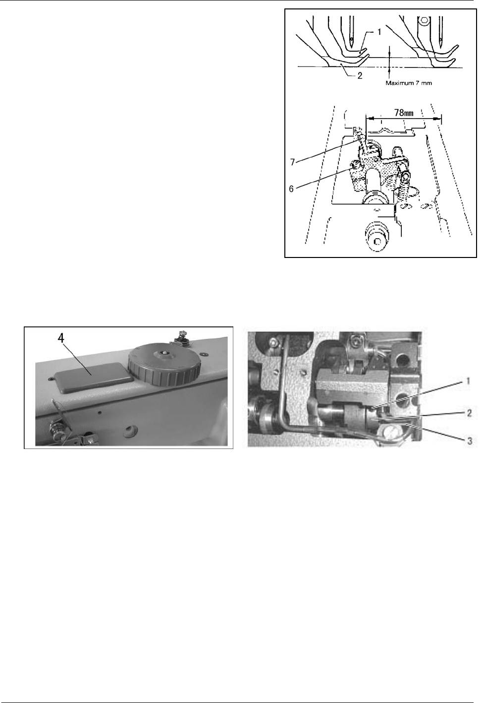
24) Adjusting the alternating presser foot movement amount(Fig.33&Fig.34)
Fig.33
Maximum alternating presser foot movement amount. Carry out the following adjustment to set the maximum
alternating movement amounts for the inner presser foot 1 and outer presser foot 2 to the maximum of 7 mm.
— 16 —
a. Remove the upper plate.
b. Remove the adjusting bracket 3.
c. Loosen screw 5 of adjusting bracket collar 4.
d. Adjust the adjusting bracket collar 4. If the adjusting
bracket collar 4 is be installed at the highest position, the
alternating presser foot movement amount is 1-6mm. If it is at the
lowest position, the alternating presser foot movement amount is
1-7mm.
e. Tighten the screw 5.
f. Install the adjusting bracket 3.
g. Loosen the bolt 6 and turn connecting lever 7 to adjust so
that the distance from the outer edge of the arm to the outer edge
of the pin 7 is 78 mm at this time. Then tighten
the bolt 6.(When installing the upper plate, set the alternating Fig.34
presser foot movements dial to the “min.” position.)
25) Adjusting the presser foot timing(Fig.35)
Fig.35
When the presser feet are lowered and the machine pulley is turned toward the user. The inner presser foot
should touch the feed dog before the needle arrives at the feed dog. Then when the needle lifts up, the tip of the
needle should move away from the feed dog before the inner presser foot moves away.
(1) Remove the upper cover 4.
(2) Loosen the two screws 1.
(3) Turn the machine pulley until the needle tip and the feed dog’s up face is the same plane.
(4) Turn inner presser cam2 to adjust so that the point of inner presser cam is facing straight up.
(5) Tight the screws 1.
(6) When installing the upper plate 4, set the alternating presser foot movement dial to the “MIN.” position.
— 17 —
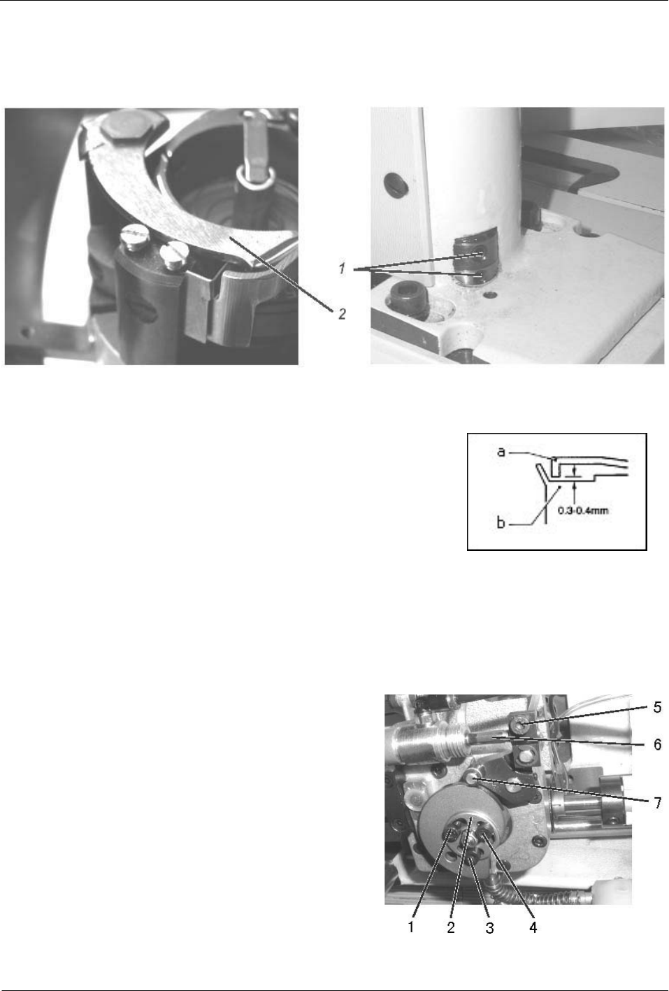
26) Driving knife adjustment
In resting position the rear edge of the driving knife should be flush with the front edge of the counter-knife,
which have been showed by Fig.36.
Fig.36
The fixed knife should abut on the thread pulling knife along its total width.
The pivoting driving knife should abut on the fixed knife after
approx.1/3 of its width.
The driving knife must not collide with the bobbin case.(Fig.37)
The clearance between the lower blade edge of the driving
knife a and the lower surface of the inner rotary hook b should
be 0.3-0.4mm.. Fig.37
Checking :
In Fig.36,loosen two screws 1 for adjusting the resting position of the driving knife and adjust the knife
according to the standard, then tighten screws 1.
ATTENTION:
Check the axial clearance of the knife shaft when
tightening the screws 1.The driving knife must be easily
movable and the axial clearance as low as possible .
27) Adjusting the thread trimming timing(Fig.38)
Checking: The moment of knife swiveling is fixed by
the position of the cam 2, When the thread lever is in position
“up”, the roller 7 should abut on the highest point of the cam
2
The roller should not touch the cam while sewing. The
distance between roller and cam should amount to 0.1mm. Fig.38
— 18 —
Adjustment: When adjust roller to cam, first, loosen screw 5 for adjusting the distance between roller and
cam ,then twist piston rod 6 in order to adjust the distance, at last ,tighten screw 5.
Turn cam adjustment: Loosen screw 1,3 and 4 at the cam, then, twist cam 2 in such a way that the roller abut
on the highest point of the cam when the thread lever is in position “up”, at last ,tighten screws 1,3 and 4 again.
28) Adjusting the fixed knife position and bobbin thread clamping(Fig.39)
Fig.39
Checking:
The clamping spring 5 has the function to hold the cut bobbin thread in order to avoid skipped stitches at the
seam beginning.
Fixed knife 4 and driving knife 6 must be in parallel position standing under a slight cutting pressure.
Parallel position correction
Loosen screw 3 slightly for adjusting the parallel position of thread pulling knife 6 and counter-knife 4,then
change counter-knife 4 by setting the screws 2 in such a way that the edges of thread pulling knife and
counter-knife are in parallel position. Tighten screw 3 at last.
Cutting pressure adjustment
The knives should guarantee a safe cut at the lowest possible pressure of the counter-knife against the
thread pulling knife. This is normally the case when the edge of the counter-knife just touches the thread pulling
knife with a knife overlapping of 1/3.
Loosen screws1,then turn counter-knife support in such a way that the condition is fulfilled, at last ,tighten
screw 1.
Clamping adjustment
Slightly bend the bobbin thread clamp for correcting the clamping and make a test cut by hand and check
the thread clamping.
— 19 —
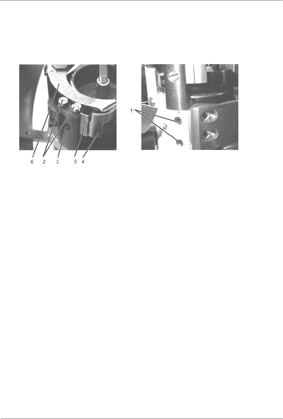
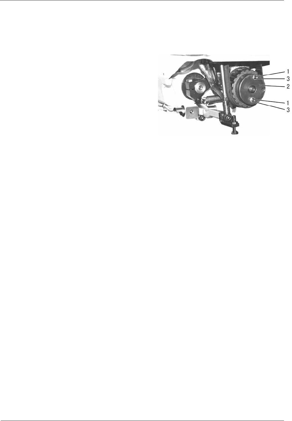
29) Safety clutch(Fig.40)
The standard safety clutch 2 in the lower toothed belt wheel protects the hook from being displaced or
damaged in case of thread jamming in the hook path. When the hook is blocked, the safety clutch 2 must come
out.
(1) Set free blocked hook.
(2) Stick a pin in drill-hole 1 of the outer clutch disc.
(3) Turn the pulley until the pin can be stuck in the
drill-holes of both clutch parts.
(4) Turn the pulley forwards and backwards until the
hook is freely movable again.
(5) Pull out pin.
(6) Hold down hook and turn the pulley until safety
clutch 2 engages.
Adjust transmittable torque Fig.40
Standard checking
The supplier by means of a torque spanner should adjust the torque transmittable from safety clutch.
(1) Loosen counter-nuts 3.
(2) Adjust torque
(3) Tighten counter-nuts 3 again.
— 20 —
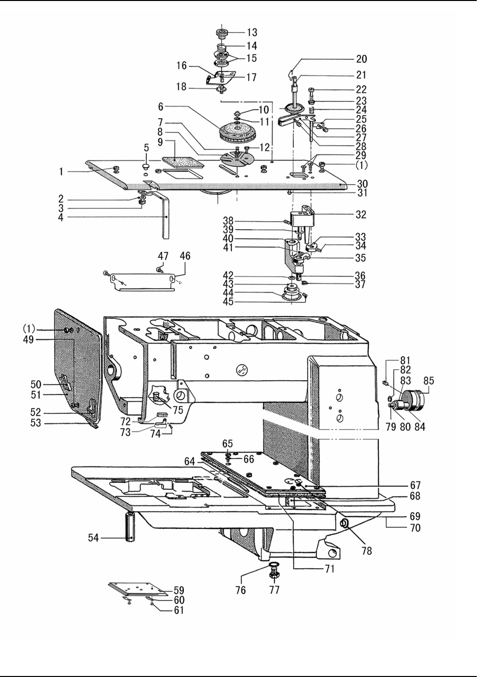
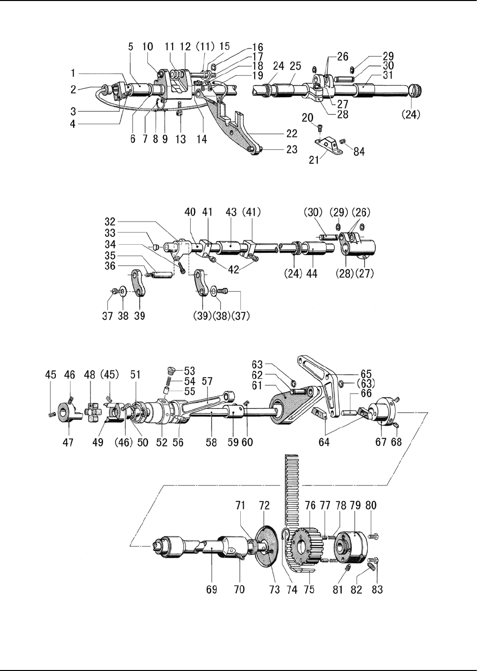
A.ARM AND ITS ACCESSORIES

— 21 —
Fig.
No. Part No. Description 2-D 1LD 1RD Remarks
A01 HF914B8001 Screw M5×12 555
A02 H005001040 Washer 111
A03 H415040080 Screw 111M4×8
A04 HF927B8001 Thread take-up cover 111
A05 HF930B8001 Plug 111
A06 HF933B8001 Dial 111
A07 HF935B8001 Dial shaft 111
A08 HF936B8001 Guard plate 111
A09 HF931B8001 Cover 111
A10 H003045040 Hexagonal nut 111M4
A11 H005001040 Washer 111
A12 H401040060 Screw 111M4×6
A13 HA710B0671 Pre-tension adjusting nut 111
A14 H6739B8001 Thread tension spring 111
A15 HA310B0705 Thread tension discs 222
A16 H6736B8001 Thread guide 111
A17 HF974B8001 Thread tension stud 111
A18 H4728H8001 Washer 111
A20 HF965B8001 Fixing clamp 111
A21 HF964B8001 Winder shaft 111
A22 H401030120 Screw 111M3×12
A23 HF952B8001 Disc 111
A24 H5731F8001 Presser spring 111
A25 HF954B8001 Knife 111
A26 H401030040 Screw 111M3×4
A27 HF947B7101 Release lever 111
A28 H401030120 Screw 111M3×12
A29 H403040080 Screw 222M4×8
A30 HF921B7101 Arm cover 111
A31 H901030080 Pin 111
A32 HF942B7101 Winder block 111
A33 HF944B8001 Release cam 111
A34 H431050060 Screw 111M5×6
A35 HF958B8001 Block 111
A36 HF955B8001 Bushing 111
A37 H007013035 E-type stop ring 3.5 111
A38 HA300E2110 Presser spring 111
A39 HF957B8001 Washer 111
A40 HF960B8001 Arm 111
A41 HF959B8001 Presser spring 111
A42 HF966B8001 Washer 222
A43 HF967B8001 Winder wheel 111
A.ARM BED AND ITS ACCESSORIES

— 22 —
Fig.
No. Part No. Description 2-D 1LD 1RD Remarks
A44 HF969B8001 Rubber ring 111
A45 H431050050 Screw 111M5×5
A46 HF999B8001 Cord cover 111
A47 H7331G8001 Screw 111
A49 HF915B8001 Screw M5×12 111
A50 HF918B8001 Bar 111
A51 HF913B8001 Face plate 111
A52 HF919B8001 Bar 111
A53 HF920B8001 Oil pillow 111
A54 HF998B8001 Leg 111
A59 HF985B8001 Slide Plate 111
A60 HF986B8001 Spring for slide plate 222
A61 H401020025 Screw 222M2×2.5
A64 HF938K8001 Pipe 111
A65 HF914B8001 Screw M5×12 10 10 10
A66 HF997B8001 Gasket 10 10 10
A67 HF991B8001 Cover 111
A68 HF992B8001 Oil indicator 111
A69 HF993B8001 Screw 111
A70 HF994B8001 Gasket 111
A71 HF995B8001 Gasket 11 1
A72 H3108B0692 Felt 111
A73 H3108B0691 Thread guide 111
A74 HF938C8001 Screw 111
A75 HA307B0674 Rubber plug 111
A76 HF90AB8001 Gasket 222
A77 100010 Screw 111M10×1
A78 HG605H8001 Rubber plug 111
A79 HF981I8001 Pin 111
A80 H7335C8001 Washer 222
A81 H428080120 Screw 111M8×12
A82 H007013060 E-type stop ring 6 111
A83 628ZZ Bearing 222
A84 HF980I8001 Spacer 111
A85 HF979I8001 Belt tensioner 111
A.ARM BED AND ITS ACCESSORIES
— 23 —
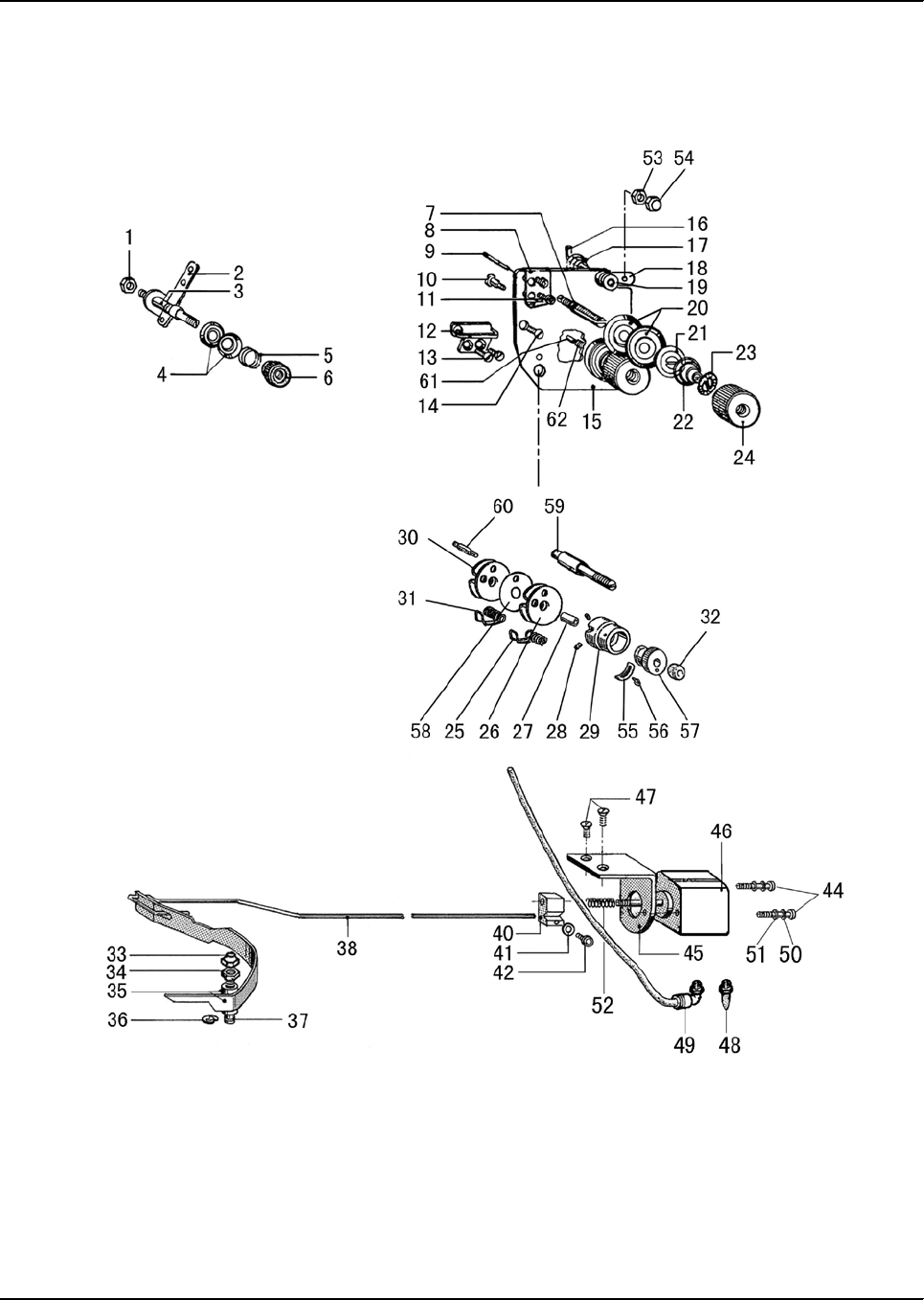
B.THREAD TENSION REGULATOR MECHANISM

— 24 —
Fig.
No. Part No. Description 2-D 1LD 1RD Remarks
B01 H003002050 Nut 211M5
B02 HF930C8001 Thead hook 211
B03 HF929C8001 Thread tension stud 211
B04 HA112B0693 Thread tension discs 211
B05 HA710B0672 Tension spring 211
B06 HA710B0671 Tension adjusting nut 211
B07 H3221B0686 Thread tension stud 111
B08 HF917C8001 Thread guide 111
B09 H3221B6817 Thread tension releasing pin 122
B10 H3221B6811 Shoulder screw 222
B11 H7316B8001 Screw 222
B12 HG005C8001 Thread guide 1
B12 HF925C8001 Thread guide 1 1
B13 H7322B8001 Screw 222
B14 H7316B8001 Screw 222
B15 HF905C8001 Tension plate 111
B16 HF923C8001 Rod 111
B17 HF924C8001 Sping 111
B18 HF915C8001 Tension release plate 111
B19 HF916C8001 Thread guide 111
B20 HA310B0705 Tension discs 444
B21 HA310B0702 Tension release discs 222
B22 HA115B0703 Tension spring 111
B23 HA115B7010 Stopper 222
B24 HA310B0701 Tension nut 222
B25 H4712C8001 Thread take-up spring 1
B26 H32481BF21 Plate complete 111
B27 H32481B821 Bushing 1
B28 H32481B521 Screw 2
B28 H431050050 Screw 1 1
B29 H32481B621 Take-up spring guide 1
B30 H32481BD21 Plate complete 111
B31 H4713C8001 Thread take-up spring 111
B32 H32481B721 Thumb nut 111
B33 H003045050 Nut 111M5
B34 H003002050 Nut 111M5
B35 HF918C8001 Release lever 111
B36 H007013050 E-type stop ring 5 111
B37 HF919C8001 Bolt 1 1 1
B38 HF921C8001 Hook 111
B39 H4710C8001 Tension spring 111
B40 HG110C8001 Block 111
B41 H005001040 Washer 111
B.THREAD TENSION REGULATOR MECHANISM

— 25 —
Fig.
No. Part No. Description 2-D 1LD 1RD Remarks
B42 H415040080 Screw 111M4×8
B43 HF927I8001 Washer 111
B44 H415040350 Screw 222M4×35
B45 HF906C8001 Magnet support 111
B46 HG107C8001 Pump 111
B47 H403050120 Screw 222M5×12
B48 HG108C8001 Silencer 111
B49 HF937E8001 Coupling 111EPL-04 M5
B50 H005009040 Spring Washer 222
B51 H005001040 Washer 222
B52 H3100G2050 Spring 111
B53 H003002040 Nut 111
B54 H003045040 Nut 111
B55 H32481BB21 Stopper 1
B56 H32481BC21 Screw 1
B57 H32481B921 Thread tension post 1
B58 H32481BE21 Plate complete 1
B59 HG008C8001 Thread tension stud 1
B59 H4805C8001 Thread tension stud 1 1
B60 HG007C8001 Screw 1
B60 H4804C8001 Screw 1 1
B61 HG009C8001 Tension release discs 1
B62 H3221B0689 Thread tension stud 1
B.THREAD TENSION REGULATOR MECHANISM
— 26 —
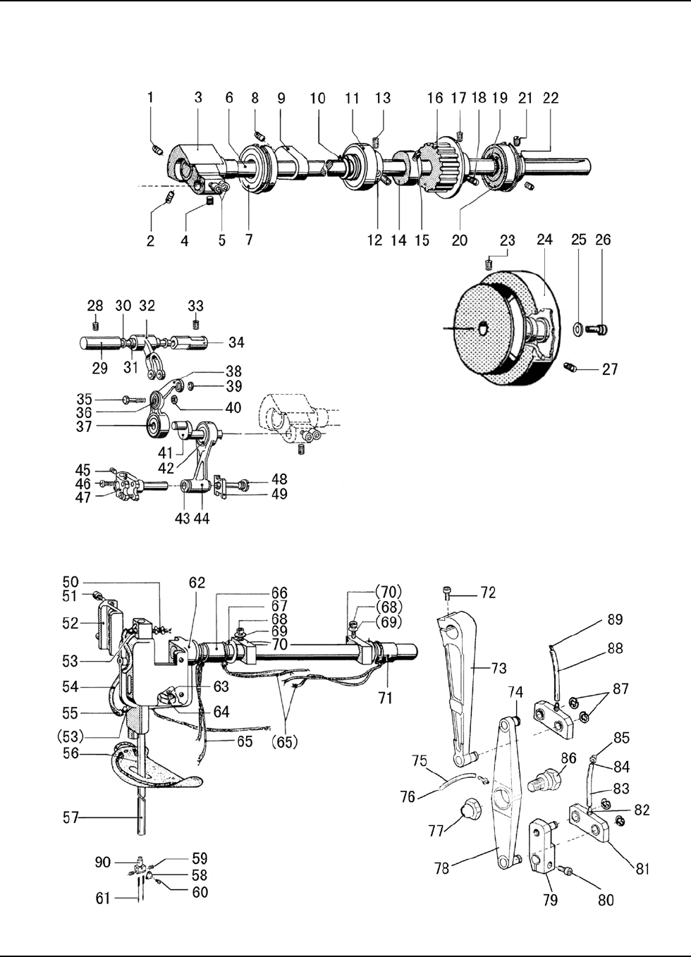
C.ARM SHAFT MECHANISM

— 27 —
Fig.
No. Part No. Description 2-D 1LD 1RD Remarks
C01 H6715C8001 Screw 111
C02 H431060080 Screw 111M6×8
C03 HF907D8001 Crank 1 1 1
C04 H431060060 Screw 111M6×6
C05 HF914B8001 Screw 222
C06 HF905D8001 Upper shaft 111
C07 H3205J0662 Ball bearing(L) 111
C08 H431080100 Screw 111M8×10
C09 HF913D8001 Counterweight 111
C10 H007009200 Retainer ring 111
C11 HF921D8001 Ball bearing(M) 111
C12 HF918D8001 Bushing 111
C13 H431060060 Screw 222M6×6
C14 HF943D8001 Bobbin winder driving wheel 111
C15 H431060100 Screw 222M6×10
C16 HG107D8001 Belt pulley(U) 111
C17 H431060080 Screw 111M6×8
C18 H429060100 Screw 111M6×10
C19 H007009200 Retainer ring 111
C20 HF932D8001 Ball bearing(R) 1 1 1
C21 H431060080 Screw 222M6×8
C22 HF929D8001 Bushing 111
C23 H431060100 Screw 111M6×10
C24 HG109D8001 Pulley 111
C25 H005008080 Washer 111
C26 H415080250 Screw 111M8×25
C27 H429060100 Screw 111M6×10
C28 H428050060 Screw 111M5×6
C29 HF913G8001 Thread take-up pin 111
C30 HF918G8001 Gasket 222
C31 H7221G8001 Needle bearing 222
C32 HF916G8001 Thread take-up support 111
C33 H428050060 Screw 111M5×6
C34 HF911G8001 Thread take-up pin bushing 111
C35 HF919G8001 Support screw 111
C36 HF909G8001 Bearing 111
C37 HF910G8001 Bearing 111
C38 HG107G8001 Thread take-up lever 111
C39 HF908G8001 Bushing 111
C40 H003008040 Nut 111M4
C41 HF920G8001 Thread take-up crank 111
C42 HF923G8001 Bearing 222
C43 HF926G8001 Bushing 111
C.ARM SHAFT MECHANISM

— 28 —
Fig.
No. Part No. Description 2-D 1LD 1RD Remarks
C44 HF922G8001 Needle bar link 111
C45 H431030050 Screw 111M3×5
C46 H401040100 Screw 222M4×10
C47 HF924G8001 Needle bar holder 111
C48 HF928G8001 Threaded bolt 111
C49 HF927G8001 Slide block 111
C50 HF938G8001 Oil wick(Short) 111
C51 H415040100 Screw 222M4×10
C52 HF933G8001 Slide guide 111
C53 HF939G8001 Oil feeding pipe 222
C54 HF936G8001 Oil pipe 111
C55 HF937G8001 Oil wick(Long) 111
C56 HF940G7101 Rubber 111
C57 HG005G8001 Needle bar 1
C57 HF970G8001 Needle bar 1 1
C58 HG007G8001 Thread guide 1
C58 HF971G8001 Thread guide 1 1
C59 H428030030 Screw 211M3×3
C60 HG008G8001 Screw 1
C60 HF972G8001 Screw 1 1
C61 JZDP1700P23 DP×17 #23 211
C62 HF931G7101 Needle bar bracket 1 1 1
C63 H403040100 Screw 111M4×10
C64 HF943G8001 Oil satchel 111
C65 HF947G8001 Oil wick 333
C66 HF927E8001 Bushing(L) 111
C67 HF968G8001 Support disc 222
C68 H415040120 Screw 222M4×12
C69 H005001040 Washer 222
C70 HF965G8001 Collar 222
C71 HF924E8001 Bushing(R) 1 1 1
C72 H415060200 Screw 111M6×20
C73 HG133G8001 Upper feed connecting rod 111
C74 HF951G8001 Shoulder screw 444
C75 HG130G8001 Oil pipe 111
C76 HG131G8001 Oil wick 111
C77 H003045080 Nut 111
C78 HG125G7101 Pull rod assy 111
C79 HF949G8001 Connecting lever 111
C80 H415060160 Screw 111M6×16
C81 HF952G7101 Pull rod 222
C82 HF956G8001 Oil joint 333
C83 HF957G8001 Oil pipe 111
C.ARM SHAFT MECHANISM

— 29 —
Fig.
No. Part No. Description 2-D 1LD 1RD Remarks
C84 HF958G8001 Oil wick 111
C85 HF959G8001 Plug 111
C86 HG127G8001 Screw 111
C87 H007013080 E-type stop ring 8 444
C88 HG130G8002 Oil pipe 111
C89 HG131G8002 Oil wick 111
C90 HG006G8001 Collet 1
C.ARM SHAFT MECHANISM
— 30 —
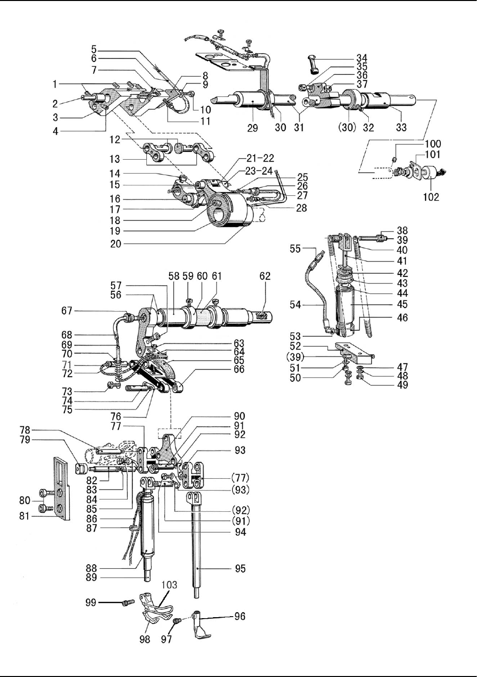
D.UPPER FEED LIFTING ROCK SHAFT MECHANISM

— 31 —
Fig.
No. Part No. Description 2-D 1LD 1RD Remarks
D01 H428050080 Screw 444M5×8
D02 HF919E8001 Support pin 111
D03 HF906E8001 Adjusting bracket(L) 111
D04 H428050080 Screw 111M5×8
D05 HF912E8001 Oil wick 111
D06 HF911E8001 Oil pipe 111
D07 HF908E8001 Oil wick 222
D08 HF913E8001 Plate 111
D09 H005018050 Washer 111
D10 H415050100 Screw 111M5×10
D100 H431040040 Screw 111M4×4
D101 HF987E8001 Holder 111
D102 HF922E8001 Potentiometer control 111
D11 HF956G8001 Oil joint 111
D12 HF917E8001 Link pin 222
D13 HF916E8001 Link 222
D14 H415060200 Screw 111M6×20
D15 HF951E8001 Connecting lever(R) 111
D16 HF956E8001 Pin 111
D17 HF953E7101 Link(R) 1 1 1
D18 HA104D0652 Plug 111
D19 HF942E8001 Inner presser cam 111
D20 H428060060 Screw 222M6×6
D21 HF946E8001 Inner presser rod 111
D22 HF947E8001 Bearing 111
D23 HF948E8001 Rod pin 111
D24 HF949E8001 Oil wick 111
D25 HF960E8001 Oil wick 111
D26 HF961E8001 Plug 111
D27 HF959E8001 Oil pipe 111
D28 HF956G8001 Oil joint 111
D29 HF924E8001 Bushing(L) 111
D30 HF923E8001 Collar 222
D31 HF921E8001 Adjusting shaft 111
D32 H431050050 Screw 222M5×5
D33 HF927E8001 Bushing(R) 1 1 1
D34 HF928E8001 Ball pin 111
D35 H415050120 Screw 111M5×12
D36 HF926E8001 Lever(R) 1 1 1
D37 H415060200 Screw 111M6×20
D38 HF940E8001 Pipe 222
D39 HF914E8001 Pin 2 2 2
D40 HF918E8001 Spring 222
D.UPPER FEED LIFTING ROCK SHAFT MECHANISM

— 32 —
Fig.
No. Part No. Description 2-D 1LD 1RD Remarks
D41 HF933E8001 Draught rod 111
D42 HF936E8001 Disc 111
D43 HF935E8001 Gasket 111
D44 HF934E8001 Piston 111
D45 HF931E8001 Pipe 111
D46 HF932E8001 Cylinder base 111
D47 HF997B8001 Gasket 222
D48 H005001050 Washer 222
D49 H415050180 Screw 222M5×18
D50 H415040160 Screw 111M4×16
D51 H005001040 Washer 111
D52 HF943E8001 Spacer 111
D53 HF937E8001 Coupling(S) 111
D54 HF938E8001 Hose 111
D55 HF939E8001 Coupling(L) 111
D56 HF962E7101 Shaft 111
D57 H415040120 Screw 111M4×12
D58 HF924E8001 Bushing 222
D59 H402050080 Screw 222M5×8
D60 HF923E8001 Collar 222
D61 HF970E8001 Sponge 111
D62 HF964E8001 Oil wick 111
D63 H415030060 Screw 111M3×6
D64 HF974E8001 Plate 111
D65 HF973E8001 Oil satchel 111
D66 HF972E8001 Draught rod 111
D67 HF961E8001 Plug 111
D68 HF983E8001 Oil pipe 111
D69 HF984E8001 Oil wick 111
D70 HF982E8001 Spring 111
D71 HF986E8001 Oil wick 111
D72 HF977E8001 Pin 111
D73 H401040040 Screw 111M4×4
D74 HF977E8001 Pin 111
D75 HF978E8001 Oil wick 111
D76 HF979E8001 Stopper claw 111
D77 HF925F8001 Joint 111
D78 HF926F8001 Pin 111
D79 HF933F8001 Slide block 111
D80 HF914B8001 Screw 222
D81 HF934F8001 Guide 111
D82 HF928F8001 Pin 111
D83 HF930F8001 Oil wick 111
D.UPPER FEED LIFTING ROCK SHAFT MECHANISM

— 33 —
Fig.
No. Part No. Description 2-D 1LD 1RD Remarks
D84 HF932F8001 Screw 111
D85 HF979E8001 Stopper claw 111
D86 HF939F8001 Oil wick 111
D87 H431050100 Screw 111M5×10
D88 HF940F8001 Bushing 111
D89 HF938F8001 Outer presser bar 111
D90 HF946F8001 Presser connecting plate 111
D91 HF977E8001 Connecting pin 222
D92 HF978E8001 Oil wick 222
D93 HF979E8001 Stopper claw 222
D94 H401040040 Screw 111M4×4
D95 HF956F8001 Inner presser bar 111
D96 HG008F8001 Inner presser foot assy 1
D96 HF959F8001 Inner presser foot assy 1 1
D97 H428040080 Screw 1
D97 HF960F8001 Screw 1 1
D98 HG105F7101 Outer presser foot assy 1
D98 HF943F8001 Outer presser foot assy 1 1
D99 H415040100 Screw 1
D99 HF944F8001 Screw 1 1
D.UPPER FEED LIFTING ROCK SHAFT MECHANISM
— 34 —
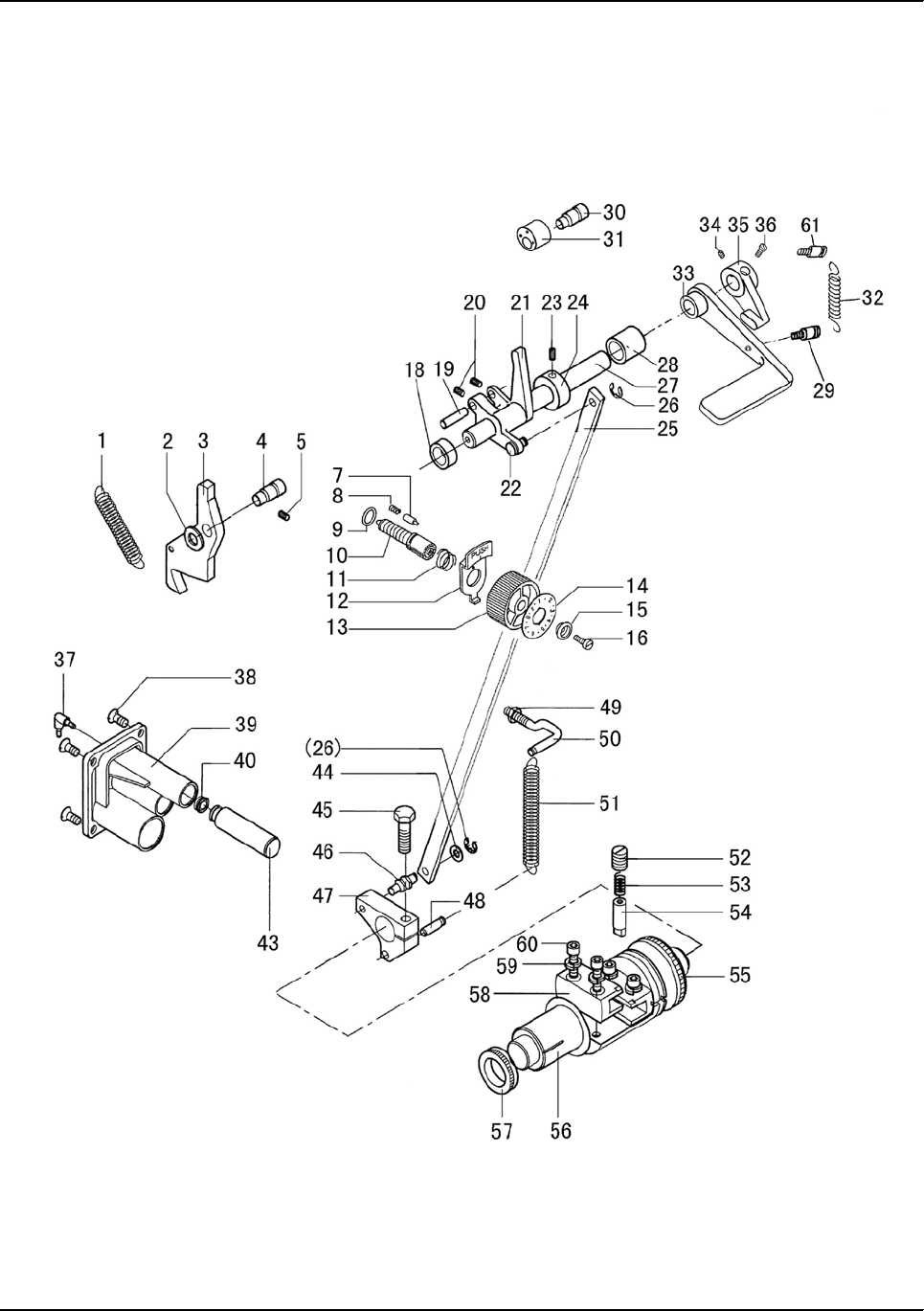
E.PRESSER FOOT ADVANCE MECHANISM

— 35 —
Fig.
No. Part No. Description 2-D 1LD 1RD Remarks
E01 H007013080 E-type retaining ring 8 111
E02 HF965F7101 Press adjusting plate assy 111
E03 HF963F8001 Pin 111
E04 HF961F7101 Press adjusting dial 111
E05 H007013050 E-type retaining ring 5 111
E06 H612030080 Spring pin 222
E07 HF976F8001 Spring support (U) 111
E08 HF972F8001 Spring 111
E09 HF975F8001 Hose 111
E10 HF973F8001 Shaft 111
E11 HF974F8001 Spring support (D) 111
E12 H428080120 Bolt 1 1 1 M8×12
E13 HF905F8001 Press-foot lifter shaft bush(L) 111
E14 HF922F8001 Oil wick 111
E15 HF919F7101 Press-foot lifter connection assy 111
E16 H605050320 Pin 111
E17 HF904F8001 Press bar lifter shaft 111
E18 HF906F8001 Spreader shaft bush(L2) 111
E19 H424050160 Set screw 111
E20 H003002050 Nut 111
E21 HF997F8001 Stopper 1 1 1
E22 HF996F8001 Crack 111
E23 H415060160 Screw 111M6×16
E24 HF910F8001 Set screw collar 111
E25 H401050060 Screw 111
E26 HF907F8001 Bushing(R) 1 1 1
E27 HF909F8001 Bushing 111
E28 HF908F8001 Bushing(R2) 111
E29 H415060200 Screw 111M6×20
E30 HF913F8001 Crack 111
E31 HF915F8001 Washer 222
E32 H005014080 Wave washer 111
E33 HF916F8001 Lifter lever 111
E34 HF917F8001 Screw 111
E35 HF980F8001 Lever(U) 111
E36 H415060160 Screw 111M6×16
E37 H415050250 Screw 111M5×25
E38 H003002050 Nut 222M5
E41 HG119F8001 Main spring 111
E46 H104060250 Screw 111M6×25
E47 HF990F8001 Knee lifter plate 111
E48 H7316E8001 Nut 111
E49 HF90IF8001 Crack 111
E.PRESSER FOOT ADVANCE MECHANISM

— 36 —
Fig.
No. Part No. Description 2-D 1LD 1RD Remarks
E50 H415060160 Screw 111
E51 HF91IF8001 Pump 111SDA32×20
E53 HF912M8001 Windpipe jiont 222EPL4-01 φ4-1/8"
E54 HF91BF8001 Coupling 111
E55 H005008060 Spring Washer 111
E57 H415040550 Screw 444
E58 H005008040 Spring Washer 444
E59 H005004040 Washer 444
E60 HF91DF8001 Washer 111
E.PRESSER FOOT ADVANCE MECHANISM
— 37 —
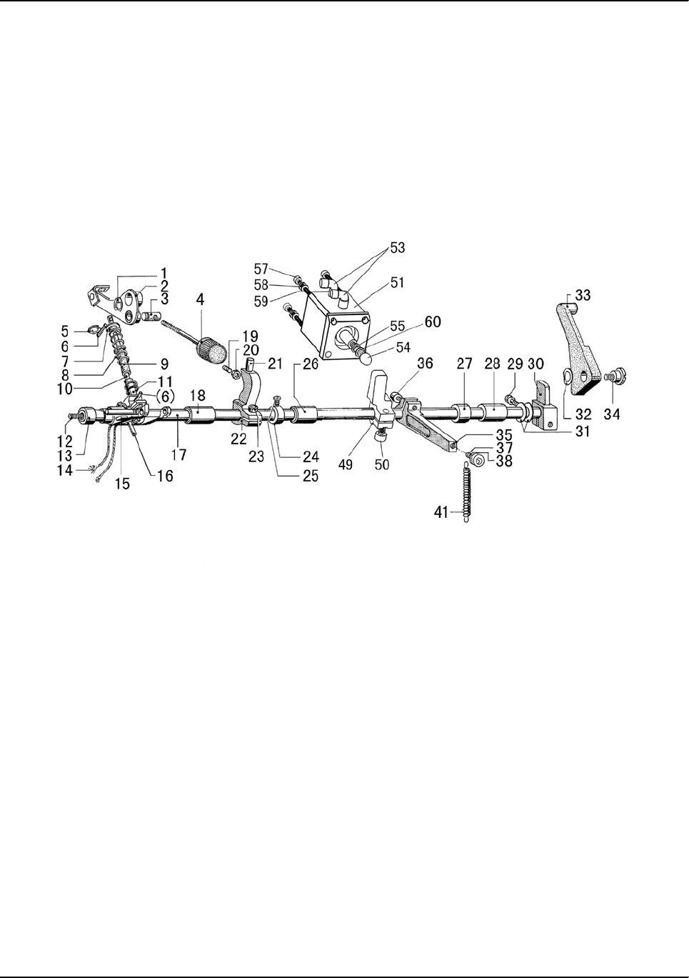
F.STITCH REGULATOR MECHANISM

— 38 —
Fig.
No. Part No. Description 2-D 1LD 1RD Remarks
F01 HF925H8001 Spring 111
F02 HF924H8001 Washer 111
F03 HG108H8001 Feed adjusting arm 111
F04 HF923H8001 Pin 111
F05 H431050080 Bolt 1 1 1 M5×8
F07 HA700F2030 Positioning pin 111
F08 H3200F2110 Spring 111
F09 HA109F0674 O ring 111
F10 HF914H8001 Feed adjusting screw (short) 111
F11 HA720F0687 Spring 111
F12 HA720F0683 Support plate 111
F13 HA7421F120 Feed adjusting dial 111
F14 HF909H8001 Feed adjusting dial plate(L) 111
F15 HA720F0685 Bushing 111
F16 HA720F0686 Screw 111
F18 HF928H8001 Reverse shaft bushing(L) 111
F19 HF932H8001 Pin 111
F20 H428060080 Bolt 2 2 2 M6×8
F21 HF930H8001 Reverse stitching arm(U) 111
F22 HF934H8001 Pin 111
F23 H428060060 Bolt 1 1 1 M6×6
F24 HF927H8001 Collor 111
F25 HG110H8001 Rod 1 1 1
F26 H007013050 E-tpye retaining ring 5 222
F27 HG112H8001 Reverse stitching shaft 111
F28 HF931H8001 Reverse shaft bushing(R) 111
F29 HK332F8001 Pin 111
F30 H4937L8001 Bolt 1 1 1
F31 H4938L8001 Rubber ring 111
F32 H4943K8001 Spring 111
F33 HG113H8001 Reverse stitching lever 111
F34 H428050060 Bolt 1 1 1
F35 HG114H8001 Reverse stitching lever block 111
F36 H428050060 Bolt 1 1 1
F37 HF937E8001 Coupling 111
F38 H403060100 Screw 444M6×10
F39 HF947H8001 Pump 111
F40 HF954H8001 Ring 1 1 1
F43 HF953H8001 Piston 111
F44 H005001060 Washer 111
F45 H104060250 Screw(D) 111M6×25
F46 HF939H8001 Bolt 1 1 1
F47 HF937H8001 Reverse stitching arm(D) 111
F.STITCH REGULATOR MECHANISM

— 39 —
Fig.
No. Part No. Description 2-D 1LD 1RD Remarks
F48 HF941H8001 Spring pin 111
F49 H003001060 Nut 111
F50 HF943H8001 Rod 1 1 1
F51 HF942H8001 Pull spring 111
F52 H424100100 Thread pin 111M10×10
F53 H3100D2090 Presser spring 111
F54 HF963H8001 Key 111
F55 HF966H8001 Oil seal 111
F56 HF958H8001 Shaft 111
F57 HF967H8001 Oil seal 111
F58 HF961H8001 Guide 222
F59 H005009050 Elastic washer 444
F60 H415050160 Screw 444M5×16
F61 HK334F8001 Pin 111
F.STITCH REGULATOR MECHANISM
— 40 —
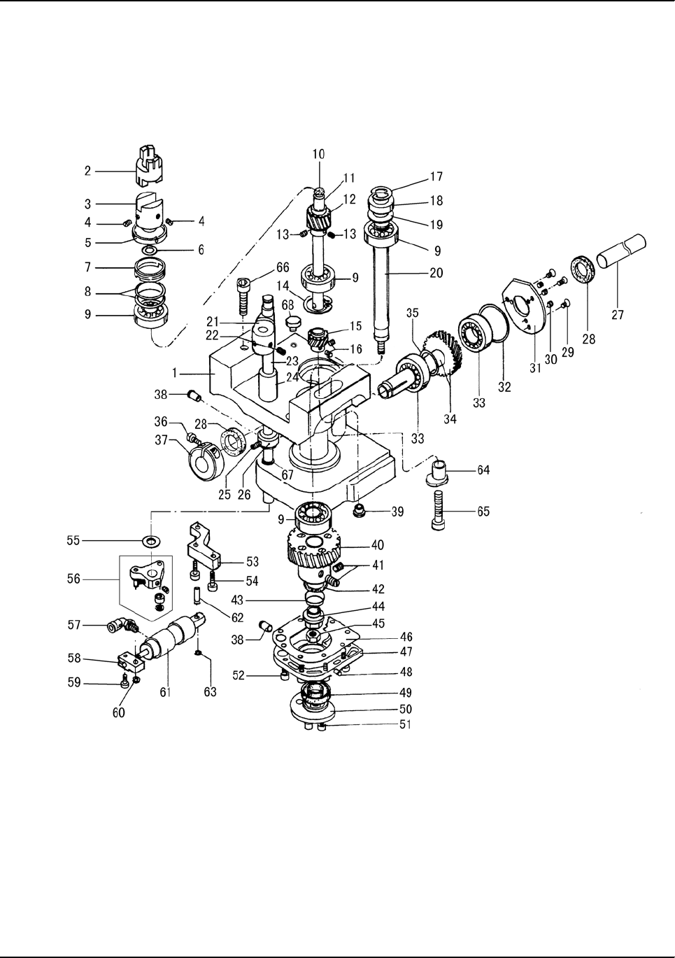
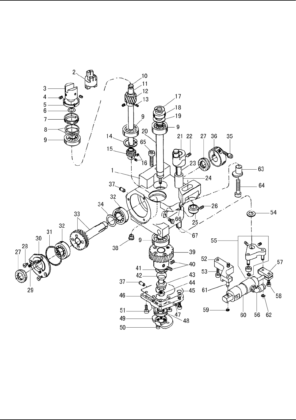
G.FEEDING AND FEED LIFTING MECHANISM

— 41 —
Fig.
No. Part No. Description 2-D 1LD 1RD Remarks
G01 HF928I8001 Feed shaft 111
G02 HF959G8001 Rubber cap 111
G03 HF965G8001 Adjusting shaft collar 111
G04 H415040120 Bolt 1 1 1 M4×12
G05 HF927E8001 Bushing(L) 111
G06 HF931I8001 Thurst ring 111
G07 H007009150 E-type retaining ring 111
G08 HF941I8001 Tube 111
G09 HF942I8001 Oil wick 111
G10 HF937I8001 Bushing 444
G11 HF945I8001 Washer 333
G12 HF935I8001 Feed arm(L) 111
G13 HF936I8001 Bolt(L) 2 2 2
G14 HF956G8001 Oil joint 111
G15 HF946I8001 Spring 222
G16 H007013050 E-type retaining ring 5 111
G17 HF944I8001 Pin 111
G18 HF939I8001 Tube support 111
G19 HF948I8001 Bolt 2 2 2
G20 H415040120 Screw 222
G21 HG107I8001 Seat 1 1 1
G22 HF949I8001 Feed bracket 111
G23 HF953I8001 Pin 111
G24 HF929I8001 Oil seal 333
G25 HF927E8001 Feed shaft bushing(L) 111
G26 HF927I8001 Washer 444
G27 H415060120 Bolt(R) 2 2 2 M6×12
G28 HF923I8001 Feed shaft arm(R) 222
G29 H007013050 E-type retaining ring 5 444
G30 HF926I8001 Pin 222
G31 HF924E8001 Feed shaft bushing(R) 222
G32 HF957I8001 Feed connecting arm(L) 111
G33 HA719B0707 Rubber cap 111
G34 H415050160 Bolt 1 1 1 M5×16
G35 HF958I8001 Pin(L) 111
G36 HF961I8001 Oil wick 111
G37 H401030080 Bolt 2 2 2
G38 HF954I8001 Washer 222
G39 HF952I8001 Feed link 222
G40 HF959I8001 Shaft 111
G41 HF965G8001 Adjusting shaft collar 222
G42 H415040120 Bolt 2 2 2 M4×12
G43 HF927E8001 Bushing(L) 1 1 1
G.FEEDING AND FEED LIFTING MECHANISM

— 42 —
Fig.
No. Part No. Description 2-D 1LD 1RD Remarks
G44 HF924E8001 Bushing(R) 111
G45 H428060100 Bolt 222M6×10
G46 H429060100 Bolt 222M6×10
G47 HF975J8001 Coupling claw(L) 111
G48 HF978J8001 Toothed wreath 111
G49 HF977J8001 Coupling craw(R) 111
G50 118026 O ring 111
G51 HF988I8001 Oil seal 111
G52 HF987I8001 Bushing(L) 111
G53 HF992I8001 Bolt 111
G54 H34412C110 Plunger spring 111
G55 HF966I8001 Plunger 111
G56 HA110E0672 Oil feeding pipe 111
G57 HF971I7101 Feed rod 111
G58 HF905I8001 Lower shaft 111
G59 HG113I8001 Feed cam 111
G60 H428060050 Bolt 222M6×5
G61 HF919I7101 Lowe feed connecting rod assy 111
G62 HF926I8001 Pin 111
G63 H007013050 E-tpye retaining ring 5 222
G64 HF961H8001 Slide block 222
G65 HF925I8001 Back sylinder connection 111
G66 HF960H8001 Pin 111
G67 HF917I8001 Lower feed cam 111
G68 H428060080 Bolt 222M6×8
G69 HF990I8001 Bushing(R) 111
G70 HF956G8001 Oil joint 111
G71 HF991I8001 Sealing ring 111
G72 HF915I8001 Disk 111
G73 HF916I8001 Stunk screw 222
G74 H007009220 Retainer ring 111
G75 HG111I8001 Toothed belt 111
G76 HG109I8001 Belt pulley(D) 111
G77 HF911I8001 Piston 222
G78 HF912I8001 Presser spring 222
G79 HF910I8001 Body 111
G80 H431060120 Adjusting screw 222M6×12
G81 H431080120 Bolt 111M8×12
G82 H430080120 Bolt 111M8×12
G83 H003002060 Nut 222M6
G84 H428040060 Bolt 111
G.FEEDING AND FEED LIFTING MECHANISM
— 43 —
H.HOOK SADDLE MECHANISM
(
1
)

— 44 —
Fig.
No. Part No. Description 2-D 1LD 1RD Remarks
H01 HG106J8001 Hook column 211
H02 HG107J8001 Bushing 211
H03 HG108J8001 Knife 211
H04 HG109J8001 Hexagonal Screw 211
H05 HG110J8001 Knife bearer cpl. 211
H06 HG111J8001 Screw 211
H07 HG112J8001 Screw 211
H08 H007013060 Lock washer 211
H09 HF945I8001 Washer 211
H10 HG115J8001 Knife shaft 211
H11 HG117J8001 Knife crank 211
H12 H431050050 Screw 422
H13 HG119J8001 Knife bearer 211
H14 H401020050 Screw 422
H15 HG121J8001 Spring 211
H16 HG122J8001 Couter knife 211
H17 H403025040 Screw 211M2.5×4
H18 H431040050 Screw 422M4(0.5)×5
H19 HG125J7101 Hook shaft 211
H20 HG127J8001 Screw 211
H21 HG128J8001 Lever 21 1
H22 HG131J8001 Lifter fork 211
H23 H415040080 Screw 211
H24 HG133J8001 Oil cushion 211
H25 HG134J8001 Washer 211
H26 H609030060 Pin 211
H27 HG136J8001 Clutch 211
H28 H428050080 Screw 422
H29 H6732K8001 Clip 211
H30 H402040060 Screw 211
H31 HG140J8001 Oil pipe 211φ4×340
H32 HG141J8001 Oil wick 211500
H33 H415060160 Screw 422
H34 H005001060 Washer 422
H35 HF971B8001 Bobbin 211
H36 HG145J7101 Hook Asm. 211
H37 HG146J8001 Washer 211
H38 HG123J8001 Pressure pin 422
H.HOOK SADDLE MECHANISM
(
1
)
— 45 —
I.HOOK SADDLE MECHANISM
(
2
)

— 46 —
Fig.
No. Part No. Description 2-D 1LD 1RD Remarks
I01 HG150J8001 Transp.column 1
I02 H415040370 Screw 1
I03 H427040060 Screw 1
I04 HG153J7101 Transp.lever 1
I05 HG156J8001 Slide block 1
I06 H007013060 Lock washer 1
I07 HG158J8001 Pin 1
I08 HG161J8001 Cover plate(right) 2
I09 HG162J8001 Cover plate(left) 2
I10 HG163J8001 Screw 8
I11 HG164J7101 Cover 2
I12 H604020180 Pin 2
I13 HG169J8001 Guide angle 1
I14 H401035080 Screw 2
I15 HG171J8001 Spring 2
I16 H401030060 Screw 2
I17 HG120J8001 Needle plate 1
I18 HG175J8001 Screw 2
I19 HG176J8001 Food dog 1
I20 HG177J8001 Screw 1
I21 HG179J8001 Plate holder 2
I22 HG163J8001 Screw 8
I23 HG181J8001 Adjust cover 2
I24 HG182J8001 Screw 2
I25 H415060160 Screw 4
I26 H005001060 Washer 4
I27 HN190J8001 Screw 2
I.HOOK SADDLE MECHANISM
(
2
)
— 47 —
J.HOOK SADDLE MECHANISM(3)

— 48 —
Fig.
No. Part No. Description 2-D 1LD 1RD Remarks
J01 HG90J78001 Transp.column 1 1
J02 H415040370 Screw 1 1
J03 H427040060 Screw 1 1
J04 HG153J7101 Transp.lever 1 1
J05 HG156J8001 Slide block 1 1
J06 H007013060 Lock washer 1 1
J07 HG158J8001 Pin 1 1
J08 HG90J88001 Cover plate 2 2
J09 HG163J8001 Screw 8 8
J10 HG164J7101 Cover 1 1
J11 H605020180 Pin 1 1
J12 H428050080 Screw 1 1
J13 H003008050 Nut 1 1
J14 HG171J8001 Spring 1 1
J15 H401030060 Screw 1 1
J16 HG91J18001 Needle plate 1
J16 HH00J68001 Needle plate 1
J17 HD726G8001 Screw 2 2
J18 HG91J38001 Food dog 1
J18 HH00J78001 Food dog 1
J19 HG177J8001 Screw 1 1
J20 HG91J48001 Adjust cover1 1 1
J21 HG91J58001 Adjust cover2 1 1
J22 HG163J8001 Screw 4 4
J23 HG181J8001 Plate holder 2 2
J24 HG182J8001 Screw 2 2
J25 H415060160 Screw 8 8
J26 H005001060 Washer 4 4
J27 HN191J8001 Screw 2 2
J28 HG91J88001 Cover plate 1 1
J29 HG91J98001 Cover plate 1 1
J.HOOK SADDLE MECHANISM(3)
— 49 —
K.GEAR SADDLE MECHANISM (LEFT)

— 50 —
Fig.
No. Part No. Description 2-D 1LD 1RD Remarks
K01 HG006J8001 Hook bearing ckl.left 1 1
K02 HG106K8001 Cross slide 1 1
K03 HG105K8001 Coupling 1 1
K04 H428050060 Screw 2 2
K05 HG107K8001 Dust cover 1 1
K06 HF989J8001 Washer 1 1
K07 HF991J8001 Oil drip ring 1 1
K08 HF992J8001 Washer 2 2
K09 HF984J8001 Ball bearing 3 3
K10 HG112K8001 Plug 1 1
K11 HF981J8001 Hook shaft 1 1
K12 HF983J8001 Gear 1 1
K13 H431050050 Screw 2 2
K14 H007007260 Retainer ring 1 1
K15 HF91AJ8001 Gear 1 1
K16 H431050050 Screw 1 1
K17 H007013080 Lock washer 1 1
K18 H005005100 Washer 1 1
K19 HG123K8001 Washer 1 1
K20 HG125K8001 Shaft 1 1
K21 HG126K7101 Lever assy. 1 1
K22 H431040060 Screw 2 2
K23 HG130K8001 Shaft 1 1
K24 HF917J8001 Bushing 1 1
K25 HF920J8001 Collor 1 1
K26 H428050050 Screw 2 2
K27 HG021J8001 Shaft 1 1
K27 HF971J8001 Shaft 1
K28 HF964J8001 Oil seal 2 2
K29 HF965J8001 Screw 3 3
K30 HF966J8001 Screw 3 3
K31 HF962J8001 Lower shaft holder 1 1
K32 387018 O ring 1 1
K33 HF963J8001 Ball bearing 1 1
K34 HF968J7101 Gear base assy 1 1
K35 HF970J8001 Washer 1 1
K36 HF973J8001 Collor 1 1
K37 H415060200 Screw 1 1
K38 HF947J8001 Oil joint 2 2
K39 HG144K8001 Plug 1 1
K40 HF91CJ7101 Gear base assy 1 1
K41 H431050060 Screw 1 1
K42 95018 O ring 1 1
K.GEAR SADDLE MECHANISM (LEFT)

— 51 —
Fig.
No. Part No. Description 2-D 1LD 1RD Remarks
K43 H005013050 Belleville spring washer 1 1
K44 HF91IJ8001 Nut 1 1
K45 HF91JJ8001 Hexagonal nut 1 1
K46 HF954J8001 Sheet packing 1 1
K47 HG154K8001 Cover 1 1
K48 HG157K8001 Oil feeding pipe 1 1
K49 HF958J8001 Oil seal 1 1
K50 HG159K8001 Disk cam 1 1
K51 H415040100 Screw 3 3
K52 H415040080 Screw 6 6
K53 HG164K8001 Bearer 1 1
K54 H415040120 Screw 2 2
K55 HG161K8001 Washer 1 1
K56 HG166K7101 Drive winch 1 1
K57 HG109C8001 Coupling 1 1 KQL04-M5
K58 HG172K8001 Block 1 1
K59 H415040080 Screw 1 1
K60 H007013040 Lock washer 1 1
K61 HG174K8001 Pump 1 1 TGM-CA1215
K62 HG175K8001 Pin 1 1
K63 H007013035 Lock washer 1 1
K64 HF92CJ8001 Bushing 1 1
K65 H415060220 Screw 1 1
K66 H415060400 Screw 1 1
K67 HF919J8001 Bushing 11
K68 HG181K8001 Screw 1 1
K.GEAR SADDLE MECHANISM (LEFT)
— 52 —
L.GEAR SADDLE MECHANISM (RIGHT)

— 53 —
Fig.
No. Part No. Description 2-D 1LD 1RD Remarks
L01 HF945J8001 Hook bearing ckl.left 1 1
L02 HG106K8001 Cross slide 1 1
L03 HG105K8001 Coupling 1 1
L04 H428050060 Screw 2 2
L05 HG107K8001 Dust cover 1 1
L06 HF989J8001 Washer 1 1
L07 HF991J8001 Oil drip ring 1 1
L08 HF992J8001 Washer 2 2
L09 HF984J8001 Ball bearing 3 3
L10 HG112K8001 Plug 1 1
L11 HF981J8001 Hook shaft 1 1
L12 HF983J8001 Gear 1 1
L13 H431050050 Screw 2 2
L14 H007007260 Retainer ring 1 1
L15 HF91AJ8001 Gear 1 1
L16 H431050050 Screw 1 1
L17 H007013080 Lock washer 1 1
L18 H005005100 Washer 1 1
L19 HG123K8001 Washer 1 1
L20 HG125K8001 Shaft 1 1
L21 HG126K7101 Lever assy. 1 1
L22 H431040060 Screw 2 2
L23 HG130K8001 Shaft 1 1
L24 HF917J8001 Bushing 1 1
L25 HF920J8001 Collor 1 1
L26 H428050050 Screw 2 2
L27 HF964J8001 Oil seal 2 2
L28 HF965J8001 Screw 3 3
L29 HF966J8001 Screw 3 3
L30 HF962J8001 Lower shaft holder 1 1
L31 387018 O ring 1 1
L32 HF963J8001 Ball bearing 1 1
L33 HF968J7101 Gear base assy 1 1
L34 HF970J8001 Washer 1 1
L35 HF973J8001 Collor 1 1
L36 H415060200 Screw 1 1
L37 HF947J8001 Oil joint 2 2
L38 HG144K8001 Plug 1 1
L39 HF91CJ7101 Gear base assy 1 1
L40 H431050060 Screw 1 1
L41 95018 O ring 1 1
L42 H005013050 Belleville spring washer 1 1
L43 HF91IJ8001 Nut 1 1
L.GEAR SADDLE MECHANISM (RIGHT)

— 54 —
Fig.
No. Part No. Description 2-D 1LD 1RD Remarks
L44 HF91JJ8001 Hexagonal nut 1 1
L45 HF954J8001 Sheet packing 1 1
L46 HG180K8001 Cover 1 1
L47 HG157K8001 Oil feeding pipe 1 1
L48 HF958J8001 Oil seal 1 1
L49 HG159K8001 Disk cam 1 1
L50 H415040100 Screw 3 3
L51 H415040080 Screw 6 6
L52 HG164K8001 Bearer 1 1
L53 H415040120 Screw 2 2
L54 HG161K8001 Washer 1 1
L55 HG166K7101 Drive winch 1 1
L56 HG109C8001 Coupling 1 1 KQL04-M5
L57 HG172K8001 Block 1 1
L58 H415040080 Screw 1 1
L59 H007013040 Lock washer 1 1
L60 HG174K8001 Pump 1 1 TGM-CA1215
L61 HG175K8001 Pin 1 1
L62 H007013035 Lock washer 1 1
L63 HF92CJ8001 Bushing 1 1
L64 H415060220 Screw 1 1
L65 H415060400 Screw 1 1
L66 HF919J8001 Bushing 1 1
L67 H401050040 Screw 1 1
L.GEAR SADDLE MECHANISM (RIGHT)
— 55 —
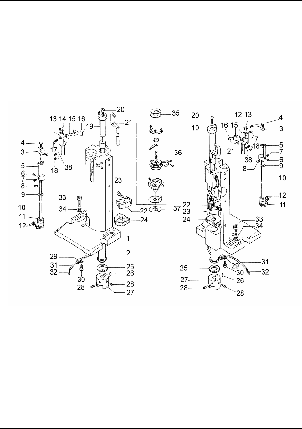
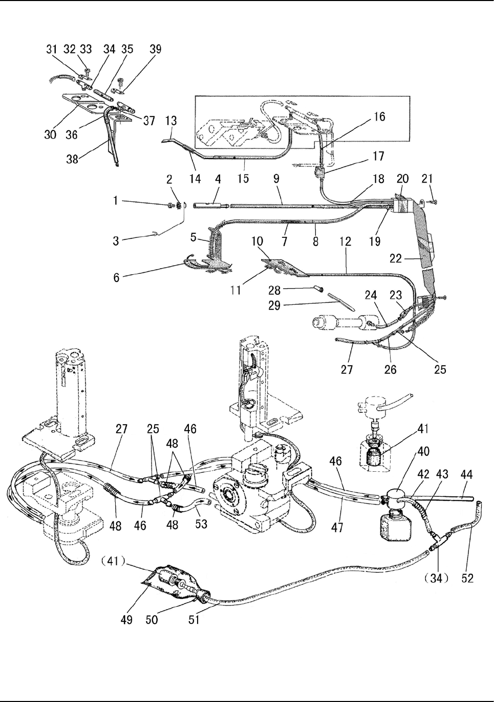
M.OIL LUBRICATION MECHANISM

— 56 —
Fig.
No. Part No. Description 2-D 1LD 1RD Remarks
M01 H401050080 Bolt 1 1 1 M5×8
M02 H005018050 Spacer 111
M03 HF909K8001 Oil wick support 111
M04 HF917K8001 Oil joint 111
M05 HF908K8001 Tube guide 111
M06 HF906K8001 Felt 111
M07 HG111L8001 Oil wick 111
M08 HG112L8001 Oil tube 111
M09 HG118L8001 Oil tube 111
M10 HF914K8001 Felt 111
M11 HG116L8001 Oil wick 111
M12 HG115L8001 Oil tube 111
M13 HF948K8001 Pipe 111
M14 HF950K8001 Oil tube 111
M15 HF949K8001 Hose 111
M16 HF936K8001 Oil pipe 111
M17 HF959K8001 Oil window 111
M18 HG119L8001 Oil pipe 111
M19 HF919K8001 Spring 111
M20 HF962K8001 Tape 111
M21 HA04042160 Screw 2 2 24.2×16
M22 HF960K8001 Guard plate 111
M23 HF956K7101 Valve 111
M24 HF955K8001 Main oil pipe 111
M25 HF920K8001 Oil joint 422
M26 HF921K8001 Oil pipe 111
M27 HF922K8001 Oil pipe 311
M27 HF922K8001 Oil pipe 2
M28 HF938K8001 Oil joint 111
M29 HF939K8001 Oil pipe 111
M30 HF951K8001 Oil pipe setting plate 111
M31 H32311D606 Oil wick setting plate 111
M32 H415040100 Screw 222M4×10
M33 H005001040 Washer 222
M34 H3210K0671 T-joint 333
M35 HF942K8001 Hose 111
M36 HF947K8001 Hose 111
M37 HF946K8001 Oil wick 111
M38 HF943K8001 Oil pipe plate assy 111
M39 H3200K0170 Wire assy 111
M40 HF927K7101 Oil hose assy 111
M41 HF963K7101 Filter pot assy 111
M42 HF929K8001 Oil pipe 111
M.OIL LUBRICATION MECHANISM

— 57 —
Fig.
No. Part No. Description 2-D 1LD 1RD Remarks
M43 HF930K8001 Support spring 111
M44 HF923K8001 Oil pipe 111
M45 HF935K8001 Oil joint 111
M46 HF924K8001 Oil pipe 4 1
M47 HF925K8001 Oil pipe 1 1
M48 HF926K8001 Support spring 422
M49 HF932K8001 Felt part 111
M50 HA300I2040 Cable tie 111
M51 HF934K8001 Oil pipe 111
M52 HF937K8001 Oil pipe 111
M53 HG005K8001 Oil pipe 1
M.OIL LUBRICATION MECHANISM
— 58 —
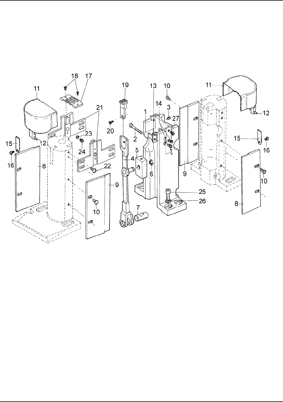
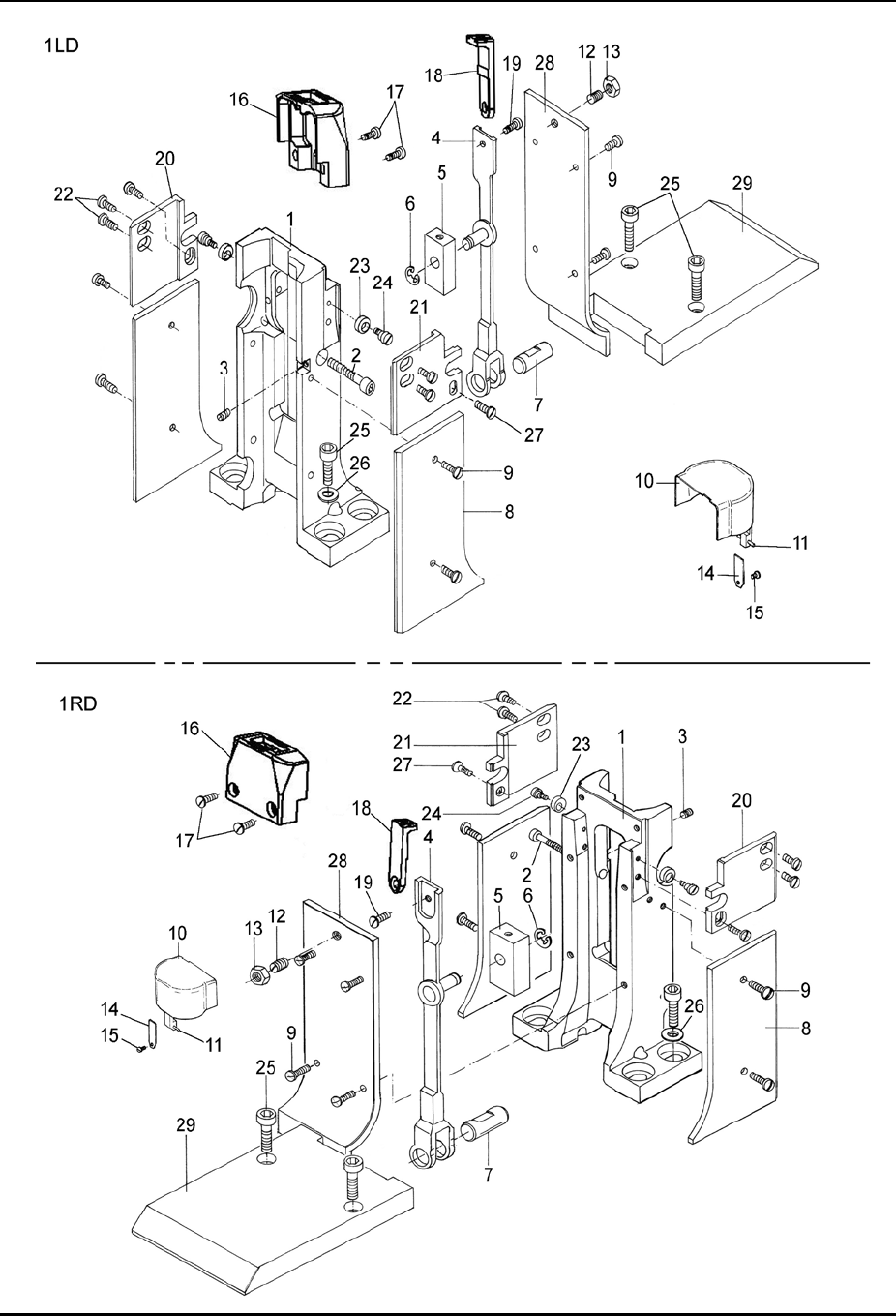
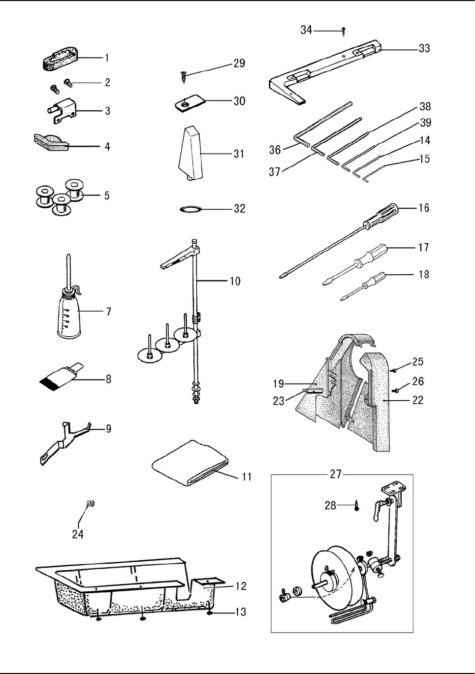
N.ACCESSORIES

— 59 —
Fig.
No. Part No. Description 2-D 1LD 1RD Remarks
N01 HG112N8001 Hinge support 222
N02 H411060100 Screw 444
N03 HG107N7101 Hinge 222
N04 HF905L8001 Head cushion 222
N05 HF971B8001 Bobbin 433
N06 HA100J2170 Oil tank 111
N07 HF912L7101 Oiler 111
N08 JZDP1700G23Neddle 644
N09 HF913L8001 Detector setting plate 111
N10 H3200L0120 Cotton stand assy 1
N10 HA200J2030 Cotton stand assy 1 1
N11 HA100J2180 Cover 111
N12 HF904L8001 Oil plate 111
N13 16250 Nail 888
N14 HB00001025 Hexagonal wrench (2.5) 111
N15 HB00001015 Hexagonal wrench (1.5) 111
N16 HA300J2070 Screw driver(L) 111
N17 HA300J2200 Screw driver(M) 111
N18 HA300J2210 Screw driver(S) 111
N19 HG108L8001 Belt guard(R) 111
N20 HF915L8001 Rubber washer 111
N21 H401060120 Bolt 111
N22 HG107L8001 Belt guard(L) 111
N23 HG158N8001 Bolt 2 2 2
N24 H005001060 Washer 333
N25 H102060100 Bolt 1 1 1
N26 H409060080 Screw 111
N27 HG120N7101 Roller holder 111Special order
N28 H804050250 Screw 444Special order
N29 H802060250 Screw 222
N30 HG111N8001 Holding plate 222
N31 HG119N8001 Stay bar 111
N32 H7331D8001 Rubber ring 111
N33 HG110N8001 Support 111
N34 H804050300 Screw 222
N.ACCESSORIES
— 60 —
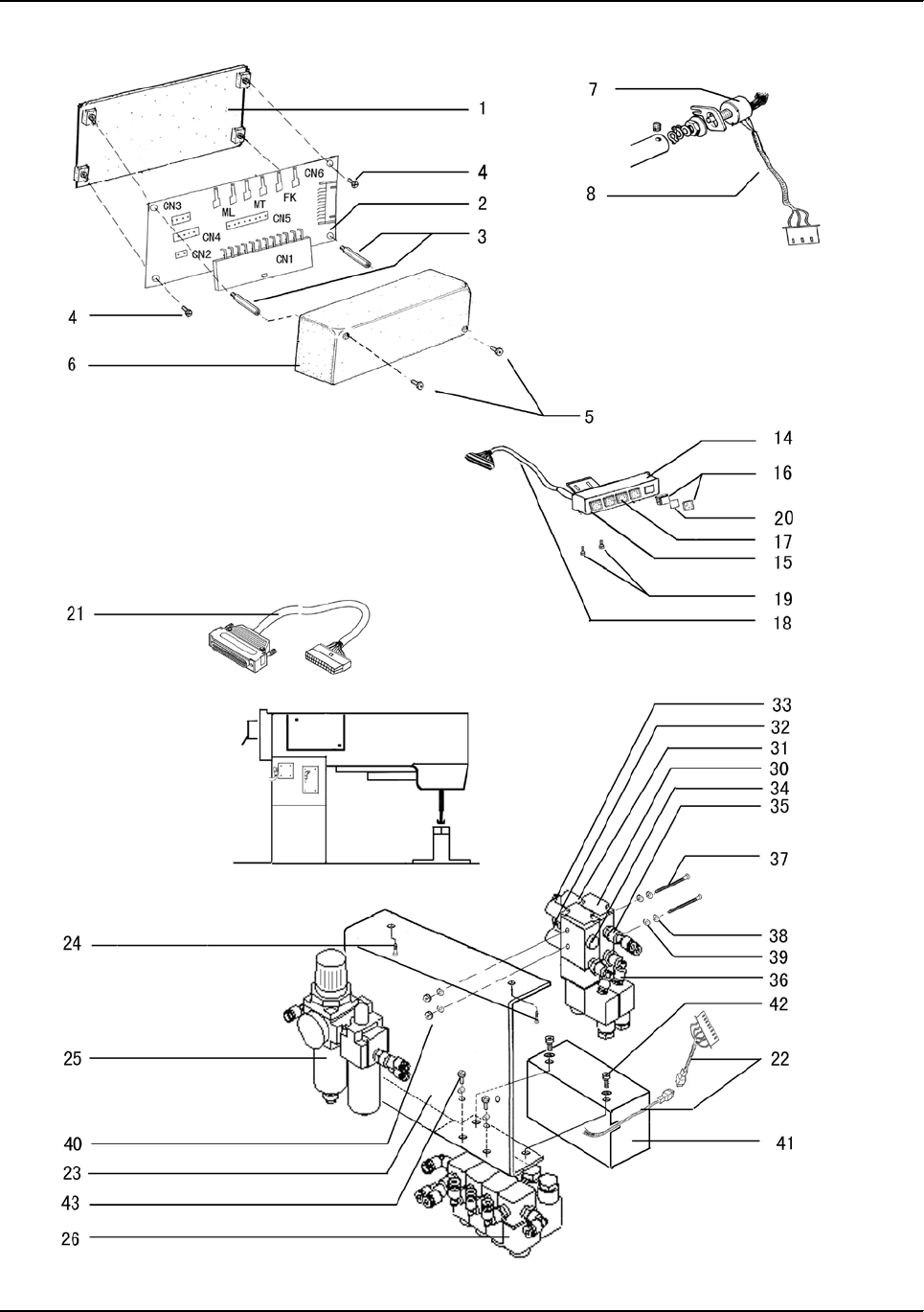
P.PNEUMATIC CONTROL UNIT

— 61 —
Fig.
No. Part No. Description 2-D 1LD 1RD Remarks
P01 HF930M8001 Connecting box base 111
P02 HF924M8001 PCB board 111
P03 HF932M8001 Connecting box screw 333
P04 H409040160 Screw 333
P05 H415030120 Screw 333
P06 HF931M8001 Connecting box cover 222
P07 HF922E8001 Rheostat 111
P08 HF989E7101 Rheostat wire assy 111
P14 HF934M8001 Button set frame 111
P14 HG90M98001 Button set frame 111
P15 HF933M8001 Button set board 111
P15 HG90M88001 Button set board 111
P16 HF937M8001 Button with light 322
P17 HF937M8002 Button without light 222
P18 HF928M7101 Button wire assy 111
P19 H415040060 Screw 444
P20 HG113M7101 Plotting 111
P21 HG91M17101 Control box wire assy 111
P22 HG125M7101 Solenoid valve wire assy 111
P23 HG127M7101 Solenoid valve set board 111
P24 HF917M8001 Screw 222
P25 HF916M7101 Air source units 111
P26 HG105M7101 Solenoid valve assy 1
P26 HG90M57101 Solenoid valve assy 1 1
P30 H4918N8001 Solenoid valve 222
P31 H4924N8001 Exhaust muffler 444
P32 H4917N8001 Wire joint 111
P33 H4916N8001 Wire joint 111
P34 HF960M8001 Screw plug 111
P35 HG119M8001 Wire joint 111
P36 HF959M8001 Wire joint 222
P37 H409040500 Screw 222
P38 H005008040 Spring washer 222
P39 H005001040 Washer 666
P40 H003002040 Nut 222
P41 HF941M8001 Solenoid valve cover 111
P42 H409040100 Screw 222
P43 HZ11040120 Screw 444
O.PNEUMATIC CONTROL UNIT

ADD: 1418, Yishan Road, Shanghai, China
Zip Code: 201103
Overseas Business: TEL: 86-21-64853303 FAX: 86-21-64854304
E-mail:highlead@online.sh.cn http://www.highlead.com.cn
The description covered in this manual is subject to change for improvement of the commodity without notice
2008.4. Printed
SHANGHAI HUIGONG NO.3 SEWING MACHINE FACTORY
