ACE&EASTMAN Rh 981A Service I3080846H User Manual
2016-09-25
User Manual: ACE&EASTMAN Rh-981A Service
Open the PDF directly: View PDF ![]() .
.
Page Count: 138 [warning: Documents this large are best viewed by clicking the View PDF Link!]
- RH-981A SERVICE MANUAL
- SAFETY INSTRUCTIONS
- CONTENTS
- 1. MECHANICAL DESCRIPTIONS
- 1-1. Upper and lower shaft mechanisms
- 1-2. Needle bar mechanism
- 1-3. Thread take-up mechanism
- 1-4. Zigzag mechanism
- 1-5. Needle bar rocking mechanism
- 1-6. Feed mechanism
- 1-7. Work clamp mechanism
- 1-8. Cloth opener mechanism
- 1-9. Cutter mechanism
- 1-10. Looper mechanism
- 1-11. Spreader mechanism
- 1-12. Double chain stitch looper mechanism
- 2. DISASSEMBLY
- 2-1. Covers and work clamp mechanism
- 2-2. Feed mechanism
- 2-3. Lubrication mechanism
- 2-4. Looper and spreader mechanisms
- 2-5. Needle bar rotating mechanism
- 2-6. Looper base mechanism
- 2-7. Needle bar, thread take-up, and zigzag mechanisms
- 2-8. Knife pipe assembly
- 2-9. Lower shaft mechanism
- 2-10. Synchronizer mechanism
- 2-11. Upper shaft mechanism
- 2-12. Cutter mechanism
- 2-13. Zigzag fork mechanism
- 3. ASSEMBLY
- 3-1. Zigzag fork mechanism
- 3-2. Cutter mechanism
- 3-3. Upper shaft mechanism
- 3-4. Lower shaft mechanism
- 3-5. Upper thread trimmer mechanism
- 3-6. Knife pipe and the knife bracket
- 3-7. Driving gear shaft mechanism
- 3-8. Needle bar, thread take-up, and zigzag mechanisms
- 3-8-1. Eliminating end play of the thread take-up on the arm
- 3-8-2. Applying grease to the ends of the thread take-up spring
- 3-8-3. Eliminating end play of the needle bar driving lever
- 3-8-4. Eliminating end play of the driving rod
- 3-8-5. The strength to tighten the set screw of ball bearing 25/20
- 3-8-6. Eliminating end play of the zigzag rock shaft
- 3-8-7. Eliminating end play of the zigzag lever
- 3-8-8. Attaching the needle bar yoke and the needle bar level feed link
- 3-8-9. Attaching the needle bar bush U and the needle bar
- 3-8-10.Eliminating end play of the needle bar block
- 3-8-11.Adjusting the needle bar in the radial direction
- 3-8-12.Attaching the needle bar block assembly
- 3-8-13.Adjusting the height of the needle bar
- 3-9. Looper base
- 3-10. Needle bar rocking mechanism
- 3-11. Looper and spreader machanisms
- 3-12. Lubrication mechanism
- 3-13. Feed mechanism
- 3-14. Synchronizer
- 3-15. Covers and work clamp mechanism
- 3-16. Safety switch
- 4. ADJUSTMENT
- 4-1. Adjusting the work clamp lift height
- 4-2. Adjusting the position of the work clamp plate
- 4-3. Adjusting the cloth opening amount
- 4-4. Adjusting the position of the work clamp
- 4-5. Adjusting the X-axis home position
- 4-6. Adjusting the Y-axis home position
- 4-7. Adjusting 0 position (reference line) of the needle
- 4-8. Adjusting the home position of the looper base
- 4-9. Fine adjustment of knife position
- 4-10. Adjusting the sideways movement of the cutter lever
- 4-11. Adjusting the height of the throat plate
- 4-12. Adjusting the height of the spreader and looper
- 4-13. Adjusting the needle and looper timing
- 4-14. Adjusting the loop stroke
- 4-15. Adjusting the height of the needle bar
- 4-16. Adjusting the clearance between the looper and needle
- 4-17. Adjusting the needle guard
- 4-18. Adjusting the spreader mounting positions
- 4-19. Adjusting the spreader timing
- 4-20. Adjusting the amount to pull the upper thread and tension release
- 4-21. Adjusting upper thread trimming
- 4-22. Adjusting the lower thread trimmer (-01 specification)
- 4-22-1. Adjusting the knife pressure
- 4-22-2. Adjusting the position of the thread trimmer arm
- 4-22-3. Adjusting the thread clamp assembly and thread clamp opener
- 4-22-4. Adjusting the thread handler
- 4-22-5. Adjusting the thread guide plate
- 4-22-6. Adjusting the amount to pull the lower thread required for thread trimming
- 4-22-7. Adjusting the amount to pull the lower thread for safety stitching
- 4-22-8. Adjusting the amount to pull the gimp
- 4-23. Adjusting the lower thread trimmer (-02, -52 specifications)
- 4-23-1. Adjusting the knife engagement
- 4-23-2. Adjusting the knife pressure
- 4-23-3. Adjusting the gimp pull force
- 4-23-4. Adjusting the gimp tension
- 4-23-5. Using gimp thread work clamp
- 4-23-6. Adjusting the auxiliary clamp arm
- 4-23-7. Adjusting the length of the lower thread to be pulled for a safe sewing start
- 4-24. Adjusting the position of the lower thread presser (-02, -52 specifications)
- 4-25. Adjusting the rotating centers of the needle bar and the looper base
- 4-26. Adjusting the needle bar stop position
- 5. POWER SUPPLY EQUIPMENT
- 6. AIR PRESSURE MECHANISM
- 7. SOFTWARE
- COVER
RH-981A
Please read this manual before using the machine.
Please keep this manual within easy reach for quick reference.
ELECTRONIC EYELET BUTTON HOLER
SERVICE MANUAL
RH-981A
i
This service manual is intended for RH-981A; be sure to read the RH-981A instruction manual before this manual.
Carefully read the “SAFETY INSTRUCTIONS” below and the whole of this manual to understand this product before you start
maintenance.
As a result of research and improvements regarding this product, some details of this manual may not be the same as those for the
product you purchased.
If you have any questions regarding this product, please contact a Brother dealer.
SAFETY INSTRUCTIONS
1. Safety indications and their meanings
This instruction manual and the indications and symbols that are used on the machine itself are provided in order to
ensure safe operation of this machine and to prevent accidents and injury to yourself or other people.
The meanings of these indications and symbols are given below.
Indications
DANGER The instructions which follow this term indicate situations where failure to follow the
instructions will almost certainly result in death or severe injury.
CAUTION The instructions which follow this term indicate situations where failure to follow the
instructions could cause injury when using the machine or physical damage to
equipment and surroundings.
Symbols
........................................ This symbol ( ) indicates something that you should be careful of. The
picture inside the triangle indicates the nature of the caution that must be
taken.
(For example, the symbol at left means “beware of injury”.)
........................................ This symbol ( ) indicates something that you must not do.
........................................ This symbol ( ) indicates something that you must do. The picture
inside the circle indicates the nature of the thing that must be done.
(For example, the symbol at left means “you must make the ground
connection”.)
RH-981A ii
2. Notes on safety
DANGER
Wait at least 5 minutes after turnin
g
off the
p
ower switch and disconnectin
g
the
p
ower cord from the wall outlet
before o
p
enin
g
the face
p
late of the control box. Touchin
g
areas where hi
g
h volta
g
es are
p
resent can result in
severe injury.
CAUTION
Environmental requirements
Use the sewin
g
machine in an area which is free
from sources of stron
g
electrical noise such as
high-frequency welders.
Sources of stron
g
electrical noise ma
y
cause
problems with correct operation.
Any fluctuations in the power supply voltage
should be within 10% of the rated voltage for
the machine.
Voltage fluctuations which are greater than this
may cause problems with correct operation.
The
p
ower su
pp
l
y
ca
p
acit
y
should be
g
reater than
the re
q
uirements for the sewin
g
machine’s
electrical consumption.
Insufficient
p
ower su
pp
l
y
ca
p
acit
y
ma
y
cause
problems with correct operation.
The
p
neumatic deliver
y
ca
p
abilit
y
should be
g
reater than the re
q
uirements for the sewin
g
machine's total air consumption.
Insufficient
p
neumatic deliver
y
ca
p
abilit
y
ma
y
cause problems with correct operation.
The ambient tem
p
erature should be within the
range of 5 to 35 during use.
Tem
p
eratures which are lower or hi
g
her than this
may cause problems with correct operation.
The relative humidit
y
should be within the ran
g
e of
45% to 85% durin
g
use, and no dew formation
should occur in any devices.
Excessivel
y
dr
y
or humid environments and dew
formation ma
y
cause
p
roblems with correct
operation.
Avoid exposure to direct sunlight during use.
Ex
p
osure to direct sunli
g
ht ma
y
cause
p
roblems
with correct operation.
In the event of an electrical storm, turn off the
p
ower and disconnect the
p
ower cord from the
wall outlet.
Li
g
htnin
g
ma
y
cause
p
roblems with correct
operation.
Installation
Machine installation should onl
y
be carried out b
y
a qualified technician.
Contact your Brother dealer or a qualified electrician
for any electrical work that may need to be done.
The sewin
g
machine wei
g
hs more than 87 k
g
.
The installation should be carried out b
y
two or
more people.
Do not connect the
p
ower cord until installation is
com
p
lete, otherwise the machine ma
y
o
p
erate if
the start switch is
p
ressed b
y
mistake, which could
result in injury.
Be sure to connect the
g
round. If the
g
round
connection is not secure,
y
ou run a hi
g
h risk of
receivin
g
a serious electric shock, and
p
roblems
with correct operation may also occur.
All cords should be secured at least 25 mm awa
y
from an
y
movin
g
p
arts. Furthermore, do not
excessivel
y
bend the cords or secure them too
firml
y
with sta
p
les, otherwise there is the dan
g
er
that fire or electric shocks could occur.
Install the belt covers to the machine head and
motor.
If usin
g
a work table which has casters, the
casters should be secured in such a wa
y
so that
they cannot move.
Be sure to wear
p
rotective
g
o
gg
les and
g
loves
when handlin
g
the lubricatin
g
oil and
g
rease, so
that the
y
do not
g
et into
y
our e
y
es or onto
y
our
skin, otherwise inflammation can result.
Furthermore, do not drink the oil or eat the
g
rease
under an
y
circumstances, as the
y
can cause
vomiting and diarrhoea.
Keep the oil out of the reach of children.
RH-981A
iii
CAUTION
Sewing
This sewing machine should only be used by
operators who have received the necessary
training in safe use beforehand.
The sewin
g
machine should not be used for an
y
applications other than sewing.
Be sure to wear
p
rotective
g
o
gg
les when usin
g
the
machine.
If
g
o
gg
les are not worn, there is the dan
g
er that if
a needle breaks,
p
arts of the broken needle ma
y
enter your eyes and injury may result.
Turn off the
p
ower switch at the followin
g
times,
otherwise the machine ma
y
o
p
erate if the start
switch is
p
ressed b
y
mistake, which could result in
injury.
When threading the needle
When replacing the needle
When not usin
g
the machine and when leavin
g
the machine unattended
If usin
g
a work table which has casters, the
casters should be secured in such a wa
y
so that
they cannot move.
Attach all safet
y
devices before usin
g
the sewin
g
machine. If the machine is used without these
devices attached, injury may result.
Do not touch an
y
of the movin
g
p
arts or
p
ress an
y
ob
j
ects a
g
ainst the machine while sewin
g
, as this
ma
y
result in
p
ersonal in
j
ur
y
or dama
g
e to the
machine.
If an error occurs in machine o
p
eration, or if abnormal
noises or smells are noticed, immediatel
y
turn off the
p
ower switch. Then contact
y
our nearest Brother
dealer or a qualified technician.
If the machine develo
p
s a
p
roblem, contact
y
our
nearest Brother dealer or a qualified technician.
Cleaning
Turn off the
p
ower switch before carr
y
in
g
out
cleanin
g
, otherwise the machine ma
y
o
p
erate if
the start switch is
p
ressed b
y
mistake, which could
result in injury.
Be sure to wear
p
rotective
g
o
gg
les and
g
loves
when handlin
g
the lubricatin
g
oil and
g
rease, so
that the
y
do not
g
et into
y
our e
y
es or onto
y
our
skin, otherwise inflammation can result.
Furthermore, do not drink the oil or eat the
g
rease
under an
y
circumstances, as the
y
can cause
vomiting and diarrhoea.
Keep the oil out of the reach of children.
Maintenance and inspection
Maintenance and inspection of the sewing
machine should only be carried out by a qualified
technician.
Ask your Brother dealer or a qualified electrician to
carry out any maintenance and inspection of the
electrical system.
Turn off the power switch and disconnect the
power cord from the wall outlet at the following
times, otherwise the machine may operate if the
start switch is pressed by mistake, which could
result in injury.
When carrying out inspection, adjustment and
maintenance
When replacing consumable parts such as the
loopers and knife
Disconnect the air hoses from the air supply and
wait for the needle on the pressure gauge to drop
to “0” before carrying out inspection, adjustment
and repair of any parts which use the pneumatic
equipment.
If the power switch and air need to be left on when
carrying out some adjustment, be extremely
careful to observe all safety precautions.
Use only the proper replacement parts as
specified by Brother.
If any safety devices have been removed, be
absolutely sure to re-install them to their original
positions and check that they operate correctly
before using the machine.
Any problems in machine operation which result
from unauthorized modifications to the machine
will not be covered by the warranty.
RH-981A iv
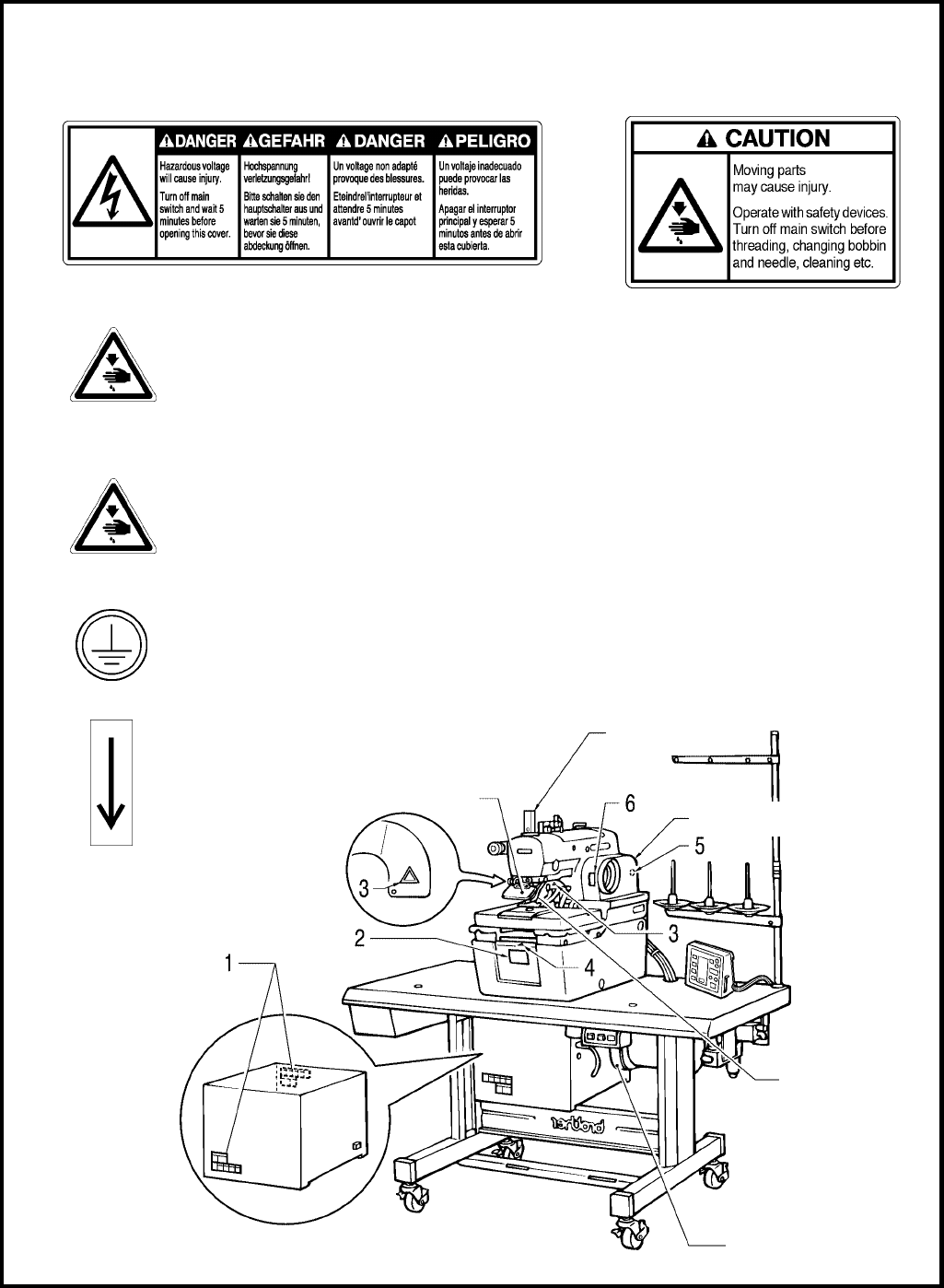
Finger guard
3. Warning labels
The following warning labels appear on the sewing machine.
Please follow the instructions on the labels at all times when using the machine. If the labels have been removed
or are difficult to read, please contact your nearest Brother dealer.
Safety devices
Eye guard
Finger guard
Needle bar guard
Belt cover, etc.
3Do not touch the knife or press any objects
against the machine while sewing, as this
may result in personal injury or damage to
the machine.
5
Be sure to connect the ground. If the ground connection is not secure, you run a high risk of
receiving a serious electric shock, and problems with correct operation may also occur.
6Direction of operation
3122Q
12
Belt cover
Needle bar guard
Eye guard
Belt cover
(Rear)
4Be careful not to clamp your fingers when
closing the front cover.

RH-981A
CONTENTS
1. MECHANICAL DESCRIPTIONS ...................1
1-1. Upper and lower shaft mechanisms ..................1
1-2. Needle bar mechanism ......................................2
1-3. Thread take-up mechanism ...............................2
1-4. Zigzag mechanism .............................................3
1-5. Needle bar rocking mechanism .........................3
1-6. Feed mechanism ................................................4
1-7. Work clamp mechanism.....................................5
1-8. Cloth opener mechanism ...................................6
1-9. Cutter mechanism...............................................7
1-10.Looper mechanism.............................................7
1-11.Spreader mechanism .........................................8
1-12.Double chain stitch looper mechanism..............9
2. DISASSEMBLY ...................................................10
2-1. Covers and work clamp mechanism ...............10
2-2. Feed mechanism ..............................................11
2-3. Lubrication mechanism ....................................11
2-4. Looper and spreader mechanisms..................12
2-5. Needle bar rotating mechanism.......................13
2-6. Looper base mechanism..................................14
2-7. Needle bar, thread take-up, and zigzag
mechanisms......................................................15
2-8. Knife pipe assembly..........................................17
2-9. Lower shaft mechanism ...................................17
2-10.Synchronizer mechanism.................................18
2-11.Upper shaft mechanism ...................................18
2-12.Cutter mechanism.............................................19
2-13.Zigzag fork mechanism ....................................19
3. ASSEMBLY...........................................................20
3-1. Zigzag fork mechanism ....................................20
3-2. Cutter mechanism.............................................21
3-3. Upper shaft mechanism ...................................22
3-4. Lower shaft mechanism ...................................23
3-4-1. Adjusting the timing belt..............................23
3-5. Upper thread trimmer mechanism ...................24
3-5-1.
Adjusting the thread trimmer lever
hammer stroke ....................................................24
3-6. Knife pipe and the knife bracket.......................25
3-7. Driving gear shaft mechanism .........................26
3-8. Needle bar, thread take-up, and zigzag
mechanisms......................................................27
3-8-1. Eliminating end play of the thread take-up
on the arm ...................................................27
3-8-2. Applying grease to the ends of the thread
take-up spring..............................................27
3-8-3.Eliminating end play of the needle bar
driving lever...................................................27
3-8-4.Eliminating end play of the driving rod ........28
3-8-5.The strength to tighten the set screw
of ball bearing 25/20.....................................28
3-8-6.
Eliminating end play of the zigzag rock shaft
.....
28
3-8-7.Eliminating end play of the zigzag lever......29
3-8-8.Attaching the needle bar yoke and
the needle bar level feed link .......................29
3-8-9.Attaching the needle bar bush U and the
needle bar.....................................................30
3-8-10. Eliminating end play of
the needle bar block..................................31
3-8-11. Adjusting the needle bar
in the radial direction ...................................... 31
3-8-12.
Attaching the needle bar block assembly
....32
3-8-13. Adjusting the height of the needle bar .....32
3-9. Looper base.......................................................33
3-10.Needle bar rocking mechanism........................34
3-10-1. Driving looper shaft ...................................34
3-10-2. Needle bar rocking mechanism ...............35
3-11.Looper and spreader machanisms ..................37
3-12.Lubrication mechanism.....................................40
3-12-1. Machine head ...........................................40
3-12-2. Driving gear shaft.......................................41
3-13.Feed mechanism ..............................................42
3-13-1. X direction...............................................42
3-13-2. Y direction...............................................43
3-13-3. Attaching the X-feed guide shaft ...........45
3-14.Synchronizer......................................................46
3-15.Covers and work clamp mechanism................47
3-16.Safety switch......................................................47
4. ADJUSTMENT.....................................................48
4-1. Adjusting the work clamp lift height..................48
4-2.
Adjusting the position of the work clamp plate ....
49
4-3. Adjusting the cloth opening amount.................50
4-4. Adjusting the position of the work clamp..........51
4-5. Adjusting the X-axis home position..................52
4-6. Adjusting the Y-axis home position..................52
4-7. Adjusting 0 position (reference line)
of the needle......................................................53
4-8. Adjusting the home position of the
looper base........................................................53
4-9. Fine adjustment of knife position......................54
4-10.Adjusting the sideways movement
of the cutter lever...............................................55
4-11.Adjusting the height of the throat plate.............55

RH-981A
4-12.Adjusting the height of the spreader
and looper..........................................................56
4-13.Adjusting the needle and looper timing............57
4-14.Adjusting the loop stroke ..................................58
4-15.Adjusting the height of the needle bar .............59
4-16.Adjusting the clearance between
the looper and needle .......................................59
4-17.Adjusting the needle guard...............................60
4-18.Adjusting the spreader mounting positions .....60
4-19.Adjusting the spreader timing...........................61
4-20.Adjusting the amount to pull
the upper thread and tension release..............61
4-21.Adjusting upper thread trimming ......................62
4-21-1. Adjusting the upper movable
knife mounting position..............................62
4-21-2. Adjusting the position of the thread
trimmer lever bracket.................................63
4-22.Adjusting the lower thread trimmer
(-01 specification).............................................63
4-22-1.Adjusting the knife pressure......................63
4-22-2.Adjusting the position of the
thread trimmer arm ....................................64
4-22-3.Adjusting the thread clamp assembly
and thread clamp opener...........................65
4-22-4.Adjusting the thread handler .....................66
4-22-5.Adjusting the thread guide plate................67
4-22-6.Adjusting the amount to pull the lower
thread required for thread trimming ..........67
4-22-7.Adjusting the amount to pull the lower
thread for safety stitching...........................68
4-22-8.Adjusting the amount to pull the gimp.......68
4-23.Adjusting the lower thread trimmer
(-02, -52 specifications).....................................69
4-23-1. Adjusting the knife engagement...............69
4-23-2. Adjusting the knife pressure......................70
4-23-3. Adjusting the gimp pull force.....................70
4-23-4. Adjusting the gimp tension ........................71
4-23-5. Using gimp thread work clamp .................72
4-23-6. Adjusting the auxiliary clamp arm.............73
4-23-7. Adjusting the length of the lower thread
to be pulled for a safe sewing start...........74
4-24.
Adjusting the position of the lower thread presser
(-02, -52 specifications)
.....................................75
4-25.Adjusting the rotating centers
of the needle bar and the looper base.............76
4-26.Adjusting the needle bar stop position.............77
5. POWER SUPPLY EQUIPMENT .................. 78
5-1. Components inside the control box................. 78
5-2. Fuse explanation .............................................. 80
5-2-1.Before replacing a fuse ............................... 81
5-3. Connectors........................................................ 82
5-3-1.Connector positions..................................... 82
5-3-2.Signal names for connectors and probable
symptoms due to poor contact ................... 86
5-4. Specification harness connections .................. 97
5-5. Summary of DIP switches................................ 98
5-5-1.Panel DIP switches ..................................... 98
5-5-2. Circuit board DIP switches ......................... 99
5-6. CHANGING FUNCTIONS USING
THE MEMORY SWITCHES.......................... 101
5-6-1. Memory switch table................................. 102
5-7. Sensors positions and funstions.................... 103
6. AIR PRESSURE MECHANISM.................. 107
6-1. Solenoid valves and air tubes........................ 107
6-1-1.Adjusting the solenoid valve speed
controllers....................................................
107
6-1-2.Air tubes..................................................... 108
6-2. Air tube layout................................................. 109
7. SOFTWARE.........................................................112
7-1. Motion flowchart.............................................. 112
7-2. Input check list ................................................ 113
7-3. Output check list ............................................. 116
7-4. List of error codes........................................... 118
7-5. Troubleshooting.............................................. 121
7-6. Control circuit block diagram (1).................... 128
7-7. Control circuit block diagram (2).................... 129

RH-981A
1. MECHANICAL DESCRIPTIONS
RH-981A
1
1. MECHANICAL DESCRIPTIONS
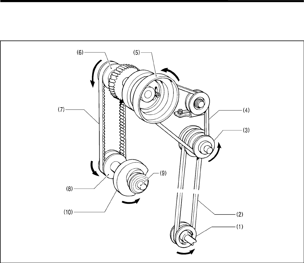
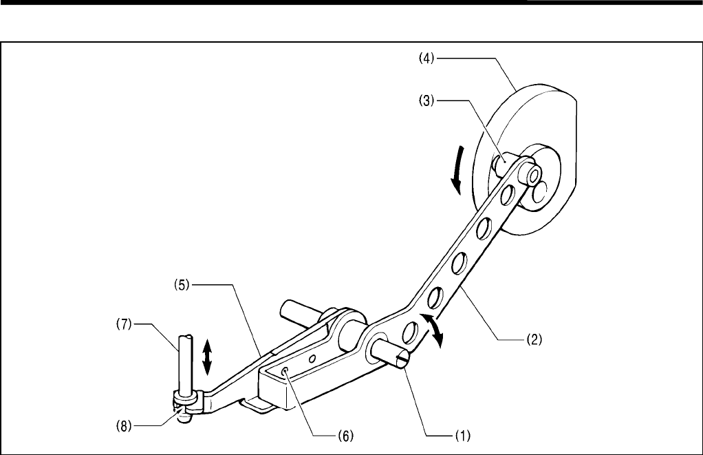
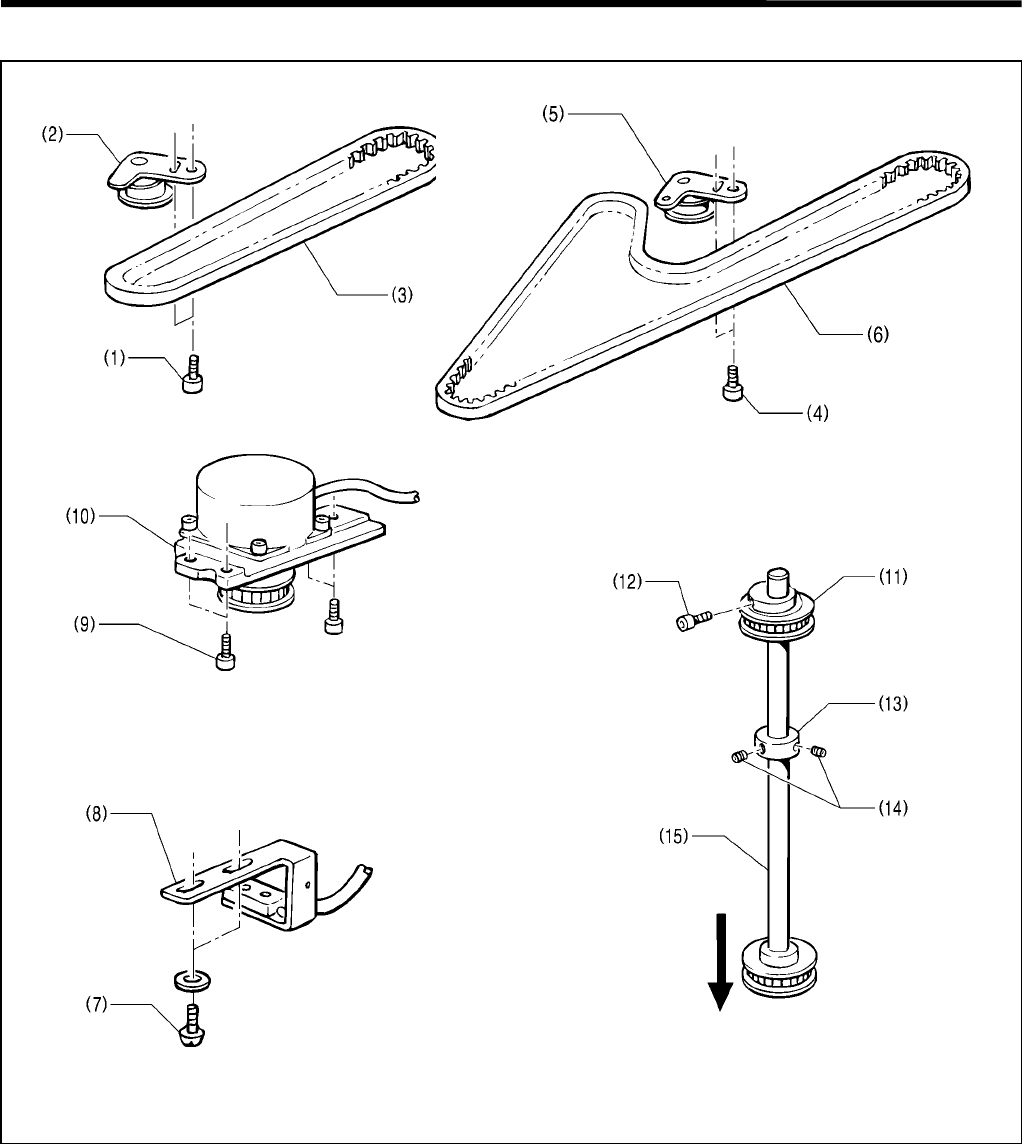
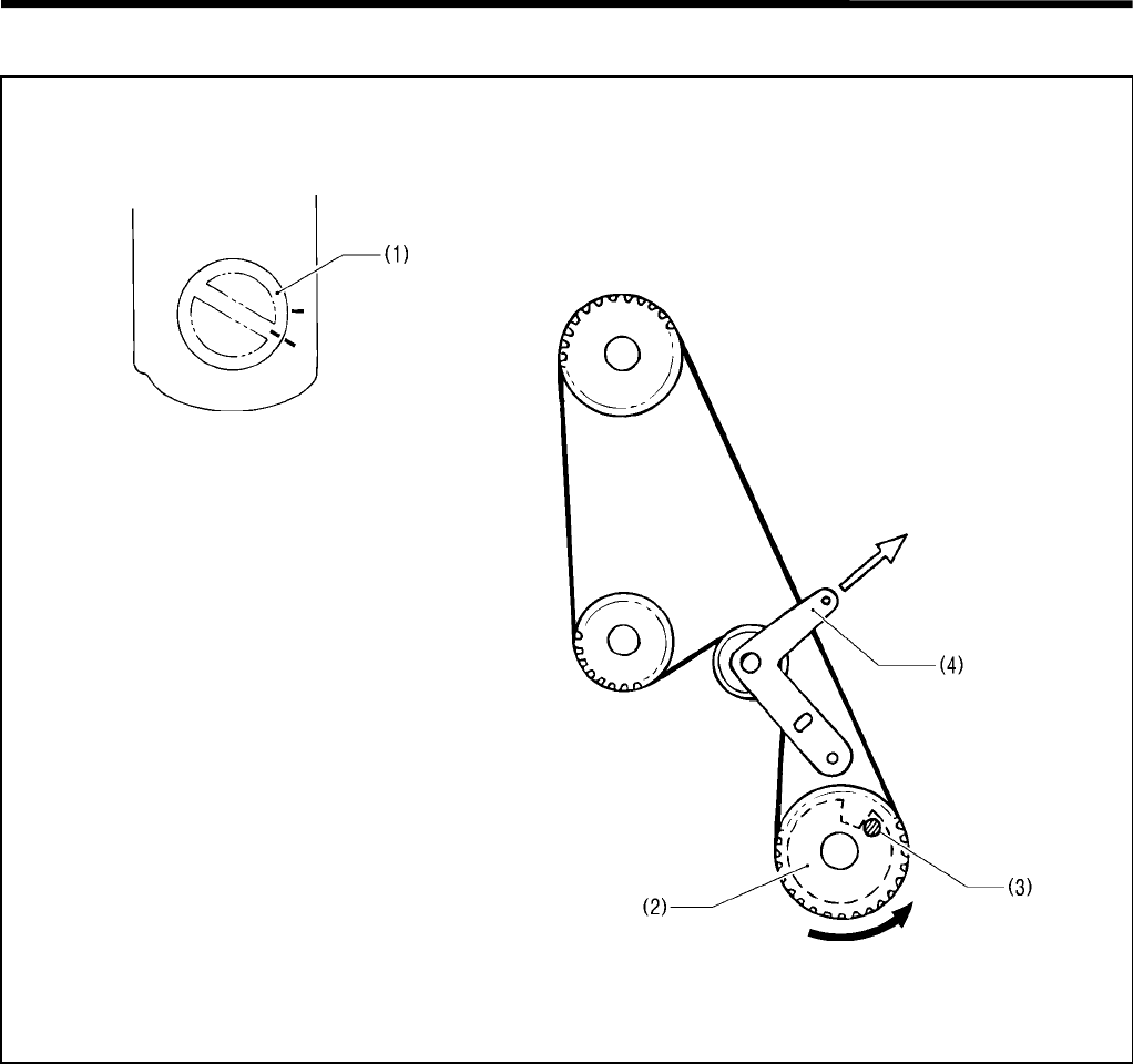
1-1. Upper and lower shaft mechanisms
1. When the motor pulley (1) rotates, its motion is transmitted to the V belt (2), the idler pulley (3), and the V belt (4),
and finally to the pulley (5).
2. When the pulley (5) rotates in the direction of the arrow, its motion is transmitted to the upper shaft timing pulley
(6), the timing belt (7), and the lower shaft tension pulley (8), and the lower shaft (9), causing the lower shaft cam
(10) to turn in the direction of the arrow.
3679Q
1. MECHANICAL DESCRIPTIONS
RH-981A 2
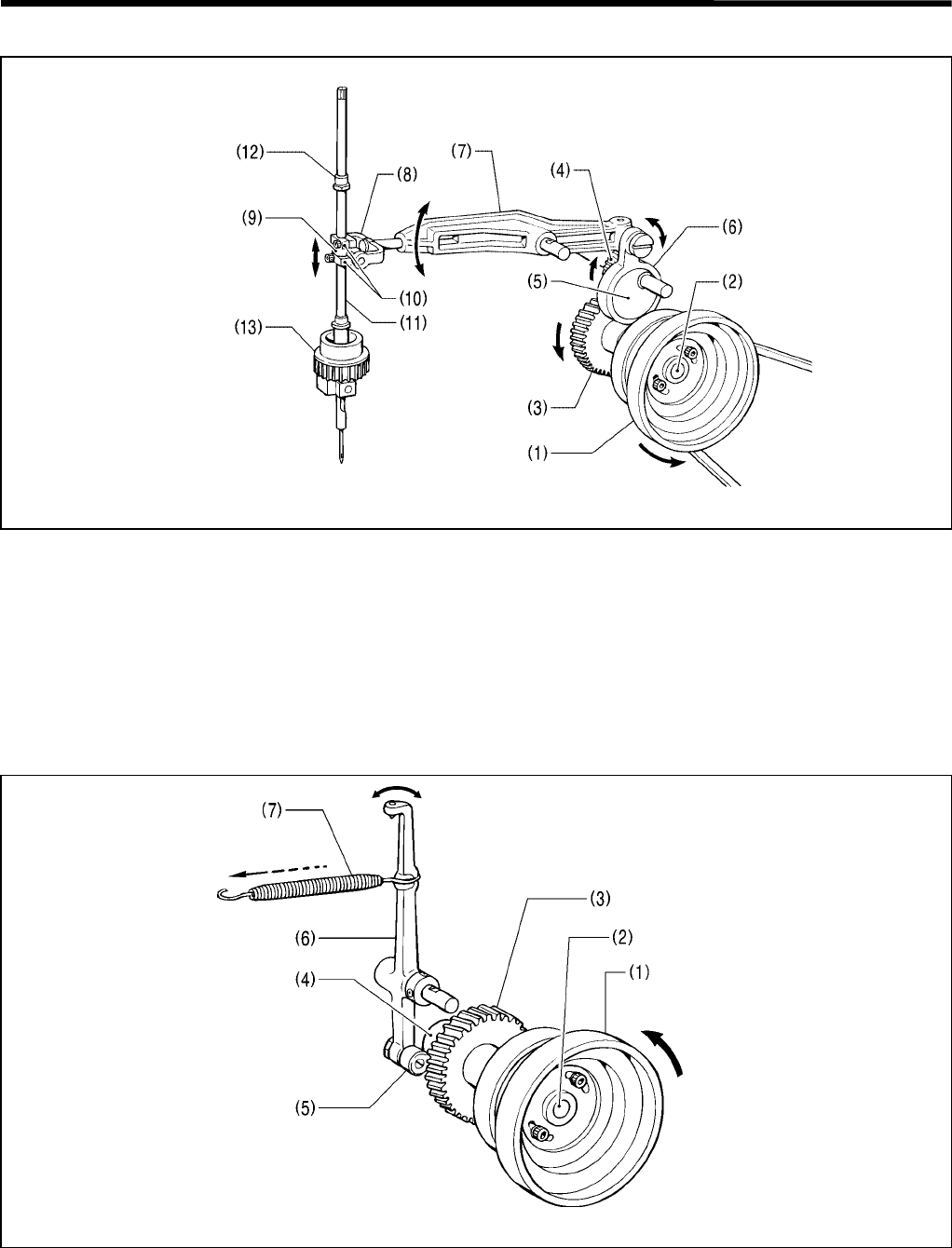
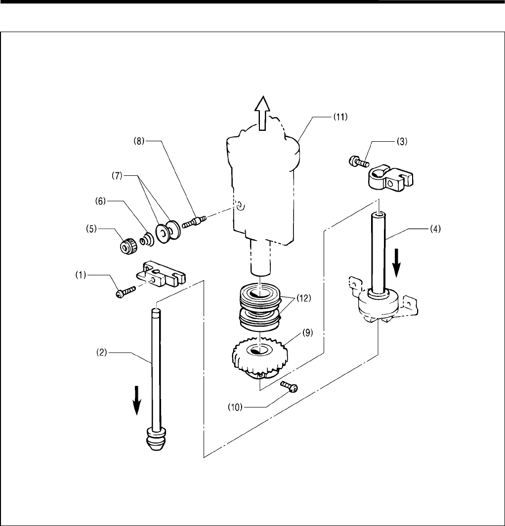
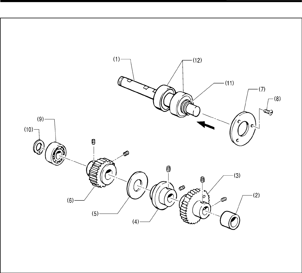
1-2. Needle bar mechanism
1. When the pulley rotates in the direction of the arrow (towards you), its rotation is transmitted to the upper shaft (2),
the needle bar gear (3), and the driving gear (4), that makes the eccentric rod (5) rotate.
2. The driving rod (6), which is engaged with the eccentric rod (5), rocks the needle bar driving lever (7).
3. The rocking motion of the needle bar driving lever (7) is transmitted to the needle bar york (8), the needle bar level
feed link (9), and the needle bar clamp (10), and then the needle bar (11) moves up and down.
4. The needle bar (11) is guided by needle bar bush U (12) and the needle bar block (13).
1-3. Thread take-up mechanism
1. When the pulley (1) rotates in the direction of the arrow, the needle bar gear (3) rotates via the upper shaft (2).
2. The thread take-up cam (4), which is attached to the needle bar gear (3), moves the thread take-up (6) via the
thread take-up cam roller (5).
3. The thread take-up cam roller (5) is always kept in contact with the cam (4) by the thread take-up spring (7)
attached to the thread take-up (6).
3681Q
3682Q
1. MECHANICAL DESCRIPTIONS
RH-981A
3
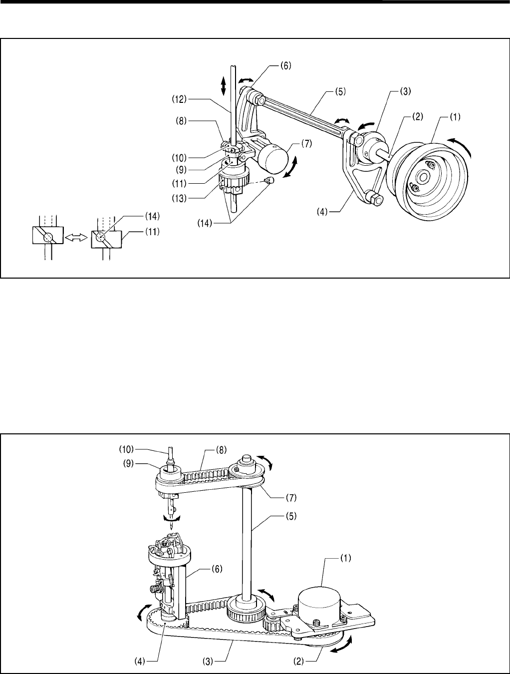
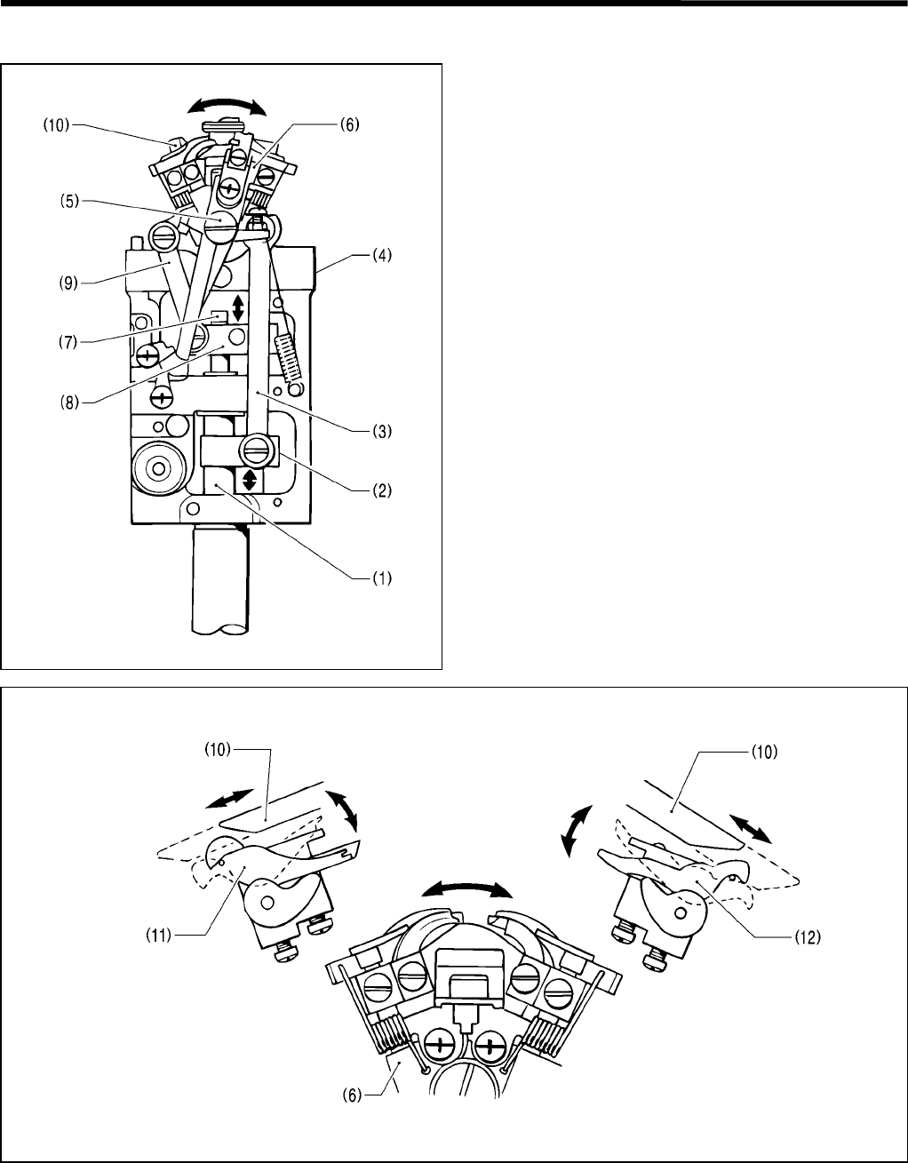
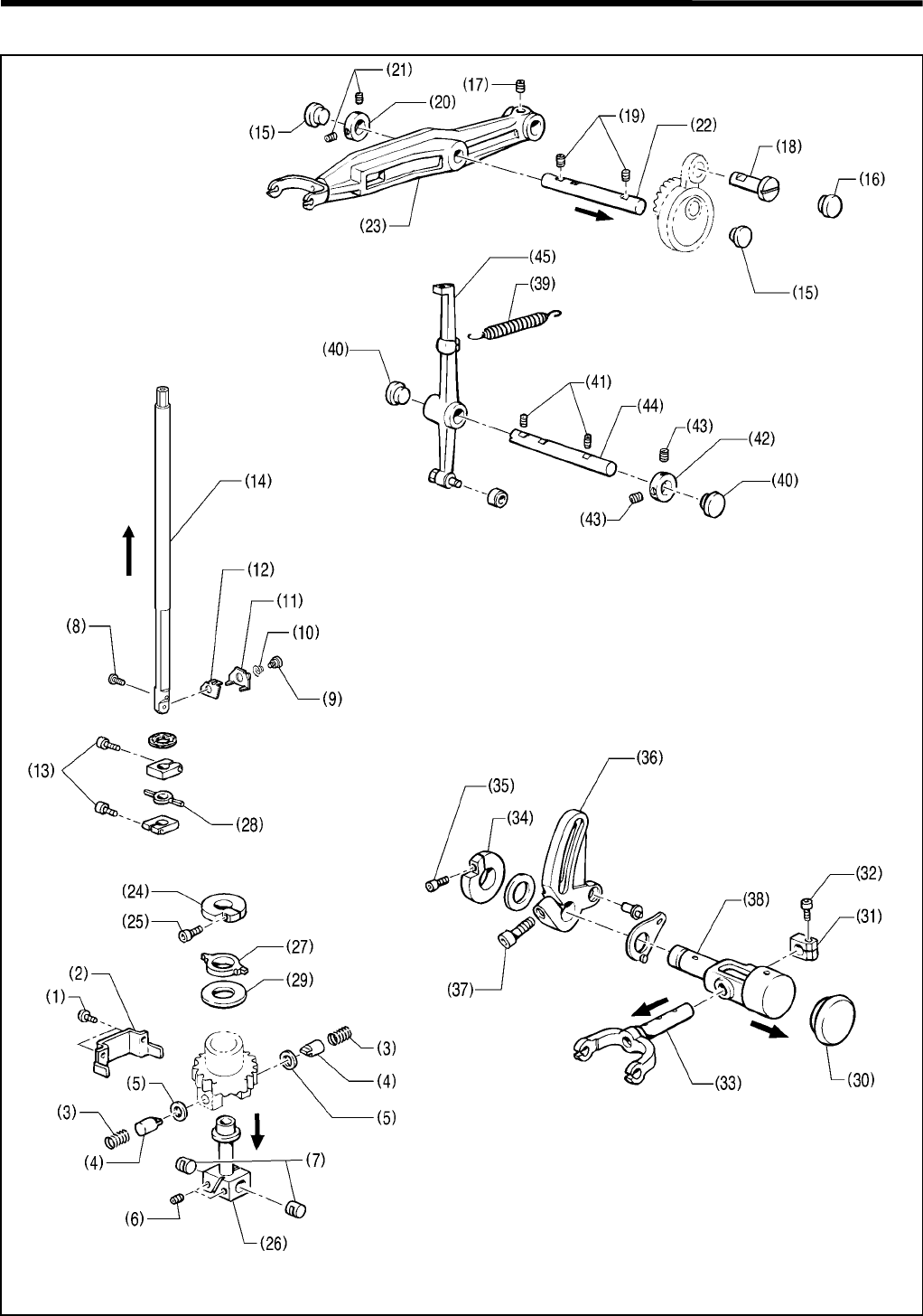
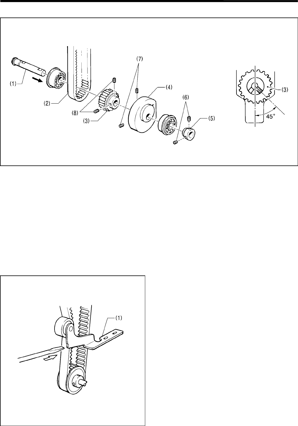
1-4. Zigzag mechanism
1. When the pulley (1) is turned in the direction of the arrow, its motion is transmitted to the upper shaft (2) that
rotates the zigzag cam (3), and the zigzag fork (4) rocks.
2. The zigzag rock shaft (7) is rocked by the zigzag fork (4), via the zigzag connecting rod (5), and the zigzag crank
(6).
3. The rocking motion of the zigzag rock shaft (7) is transmitted to the zigzag lever (8), the needle bar lever feed link
(9), and the needle bar block clamp (10), those move the needle bar block (11) up and down.
4. The needle bar (12) is fitted on the needle bar block (11), and the needle bar guide (14) is fitted in the notch of the
needle bar block (11). When the needle bar block (11) moves up and down, the needle bar (12) oscillates.
1-5. Needle bar rocking mechanism
1. When pulse motor R (1) operates, the motion is transmitted to the driving needle pulley assembly (2), timing belt
D (3), and the looper pulley assembly (4), which then moves the driving looper shaft assembly (5).
2. The looper base (6) is rotated by the looper pulley assembly (4).
3. When the vertical shaft T pulley U assembly (7), which is attached to the driving looper shaft assembly (5), rotates,
the motion is transmitted to timing belt U (8), and the needle bar block assembly (9) that rotates the needle bar (10).
3683Q
3684Q
1. MECHANICAL DESCRIPTIONS
RH-981A 4
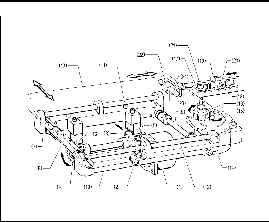
1-6. Feed mechanism
[X-direction feeding]
1. When pulse motor X (1) operates, its motion is transmitted to the actuating gear (2), the idle gears (3) and (4), and
the X racks (5) and (6), that finally moves X-feed shaft holder L (7).
2. The X-feed guide shafts A (8) and B (9), which are connected to X-feed shaft holder L (7), move X-feed shaft
holder R (10).
3. The Y-feed guide shafts (11) and (12), which are attached to X-feed shaft holders L (7) and R (10), move the feed
bar (13) in the X direction.
[Y-direction feeding]
1. When pulse motor Y (14) rotates, its motion is transmitted to the actuating gear (15), the idle gear (16), timing
pulley A (17), that finally moves the Y-timing belt (18).
2. The Y-timing belt (18) is secured by the Y-driving shaft holder (19) and the belt holder (20), and that moves the Y
shaft (21).
3. The linear bush (23), which is fitted in the ball bearing (22), is fitted in the Y-guide shaft (24) to move the feed bar
(13) in the Y direction.
X direction
3685Q
Y direction
1. MECHANICAL DESCRIPTIONS
RH-981A
5
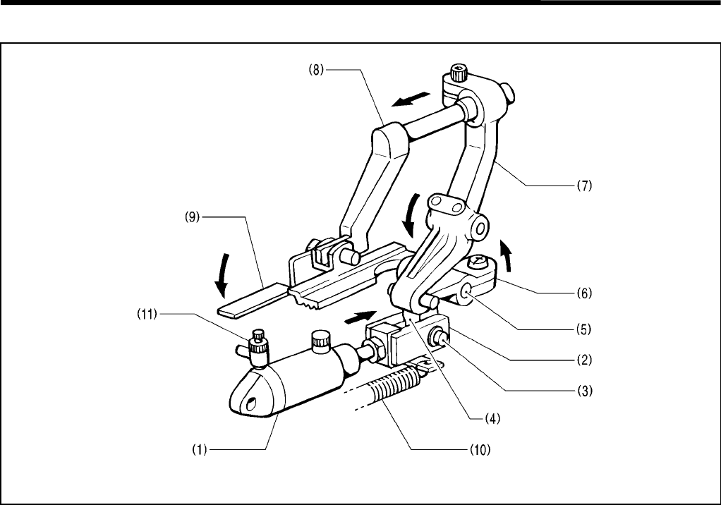
1-7. Work clamp mechanism
1. Cylinder 16 X 10 (1) moves clamp lever B (6) in the direction of the arrow according to the cylinder’s motion, via
the presser cylinder rod (2), the cylinder rod pin (3), the presser driving lever (4), and the clamp lever shaft (5).
2. The end of clamp lever B (6) is fitted on clamp lever L (7), and the work clamp (9) attached to clamp arm L (8)
lowers.
3. When the cylinder (1) is returned by the presser spring (10), the work clamp (9) rises. The speed controller (11)
attached to the cylinder (1) controls the rising speed of the work clamp (9).
* The work clamp mechanism is activated by independently-operated left and right cylinders, that can equalize the
pressure of the work clamp.
The pressure of the work clamp is always applied to the material equally even when the material thickness
changes.
3686Q
1. MECHANICAL DESCRIPTIONS
RH-981A 6
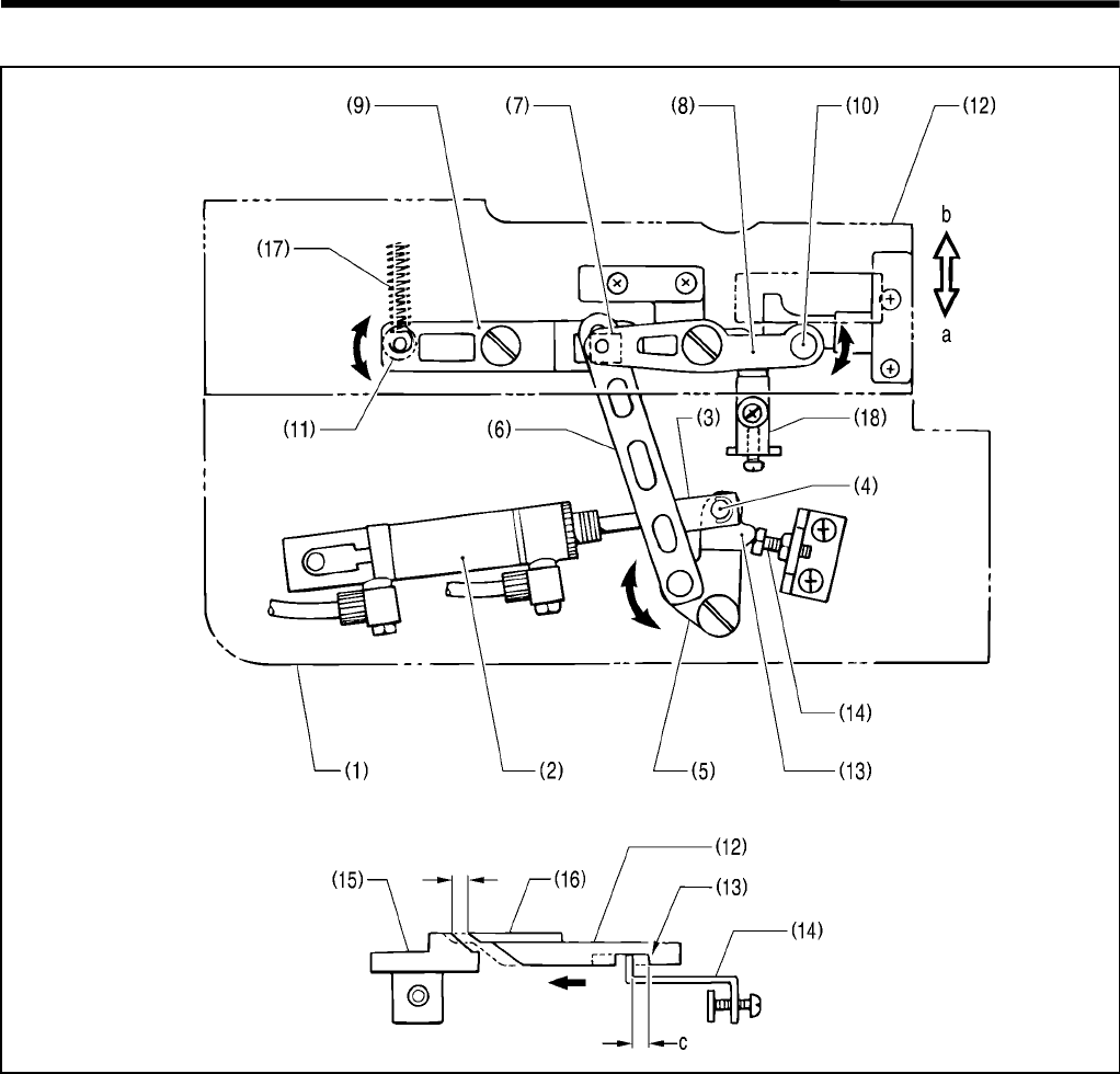
1-8. Cloth opener mechanism
1. The feed bracket (1) carries the cylinder 16 X 15 assembly (2), whose end is connected to the opening cylinder
rod (3), cylinder rod pin B (4), and the opening driving lever (5).
2. The opening connecting rod (6) attached to the opening driving lever (5) is connected to the fulcrum lever plate
(8) and the lever (9) via the slide block (7).
3. The projection (10) of the fulcrum lever plate (8) and the pin (11) of the lever (9) are fitted on the hole of the work
clamp plate (12) and the slide block on it.
4. When the cylinder 16 X 15 assembly (2) operates, and the stopper (13) of the opening driving lever (5) and the
bolt (14) make contact, the work clamp plate (12) moves in the direction of a, consequently opening a button
eyelet on the material.
5. At this time, there should be at least 1.3 mm clearance between the throat plate (15) and the needle plate (16).
Adjust the clearance using the bolt (14).
6. When the cylinder 16 X 15 assembly (2) is not pressurized, the work clamp plate (12) is moved in the direction of
b by the opening spring (17). At this time, the stopper (13) of the work clamp plate (12) makes contact with the
stopper plate (18).
* The c indicates the movement of the work clamp plate (12).
3687Q
3688Q
1.3 mm or more
1. MECHANICAL DESCRIPTIONS
RH-981A
7
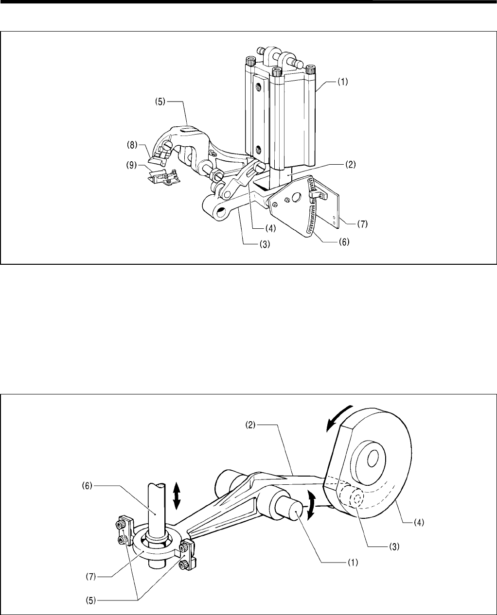
1-9. Cutter mechanism
1. When cylinder 63 X 100 (1) operates, the motion is transmitted to the cylinder rod (2), link C (3), and link A (4),
which then activates the cutter lever assembly (5).
2. The cutter sensor partition plate (6) attached to link C (3), and the cutter sensor assembly (7) monitor the motion
of the cutter sensor assembly (5).
3. Engagement of the hammer (8) attached to the end of the cutter sensor assembly (5) and the cutter (9) attached
to the bed, cuts the material requiring button eyelets.
1-10. Looper mechanism
1. At the end of the looper link assembly (2) which has the looper link support shaft (1) as the pivot of the rocking
motion, the looper cam roller (3) is fitted in the groove in the lower shaft cam (4). The two looper link springs (5)
are attached to the other end.
2. The looper link springs (5) are secured by the looper driving plate (7) through which the looper driving shaft (6)
passes.
3. When the lower shaft cam (4) rotates in the direction of the arrow, the looper link assembly (2) is rocked via the
looper cam roller (3).
4. The looper driving shaft (6) moves up and down due to the motion of the looper link assembly (2).
3689Q
3690Q
1. MECHANICAL DESCRIPTIONS
RH-981A 8
1-11. Spreader mechanism
1. At the end of the spreader cam lever (2) which has the looper link support shaft (1) as the pivot of the rocking
motion, the spreader cam roller (3) makes contact with the circumference of the lower shaft cam (4), and the
spreader driving lever (5) is attached to the other end using the screw (6). The forked part of the spreader driving
lever (5) is fitted in the groove (8) of the spreader link shaft (7).
2. When the lower shaft cam (4) rotates in the direction of the arrow, the spreader cam lever (2) is rocked via the
spreader cam roller (3).
3. The spreader link shaft (7) moves up and down due to the motion of the spreader cam lever (2).
3691Q
1. MECHANICAL DESCRIPTIONS
RH-981A
9
1-12. Double chain stitch looper mechanism
1. When the looper driving shaft (1) moves up and down,
the motion is transmitted to the looper link clamp (2),
and the looper link (3), which rocks LS-holder bracket
(6) with the holder support shaft (5) secured to the
loop base (4) regarded as the pivot.
2. When the spreader link shaft (7) moves up and down,
the motion is transmitted to the spreader link base (8)
and the spreader cam link (9), which then rocks the
spreader differential cam (10) with the holder support
shaft (5) secured to the loop base (4) regarded as the
pivot.
3. The rocking motions of the LS-holder bracket (6) and the spreader differential cam (10) cause spreader L (11) to
rock.
4. In the same way, spreader R (12) is rocked.
3692Q
3693Q
2. DISASSEMBLY
RH-981A 10
2. DISASSEMBLY
CAUTION
Disassembly should only be carried out by a
qualified technician.
Turn off the power switch before disassembly,
otherwise the machine may operate if the start
switch is pressed by mistake, which could
result in injury.
Be sure to wear protective goggles and gloves
when handling the lubricating oil and grease,
so that they do not get into your eyes or onto
your skin, otherwise inflammation can result.
Furthermore, do not drink the oil or eat the
grease under any circumstances, as they can
cause vomiting and diarrhea.
Keep the oil out of the reach of children.
Disconnect the air hoses from the air supply and
wait for the needle on the pressure gauge to drop
to “0” before disassembly of any parts which use
the pneumatic equipment.
Use only the proper replacement parts as
specified by Brother.
If any safety devices have been removed, be
absolutely sure to re-install them to their original
positions and check that they operate correctly
before using the machine.
Any problems in machine operation which result
from unauthorized modifications to the machine
will not be covered by the warranty.
If disassembly is not performed in the correct order, it may be hard to remove parts. Disassemble as follows.
The following is the main points of disassembly.
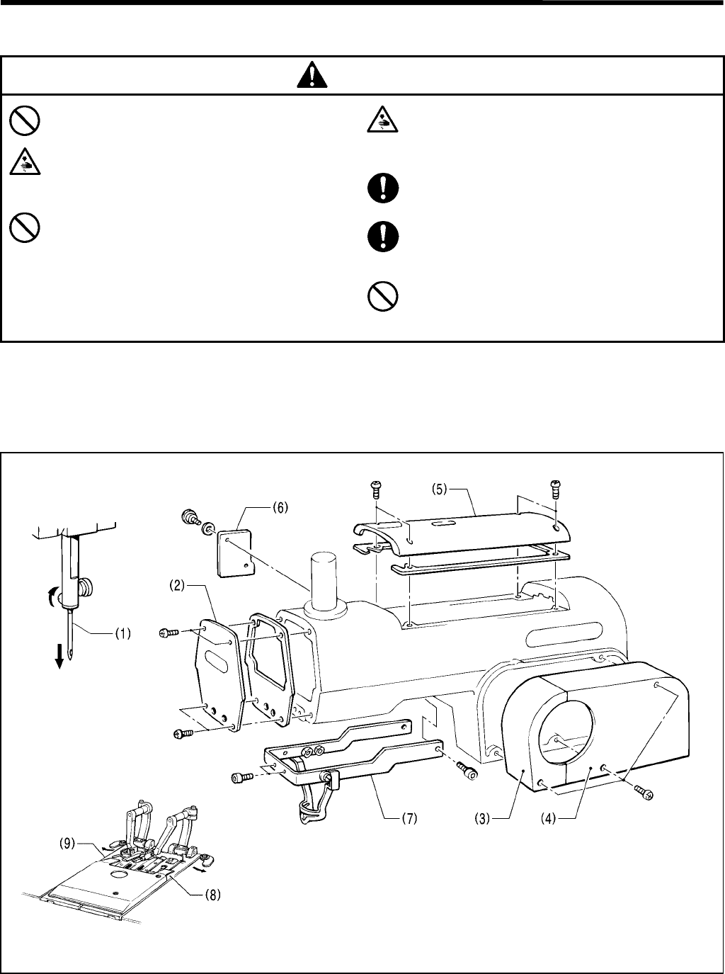
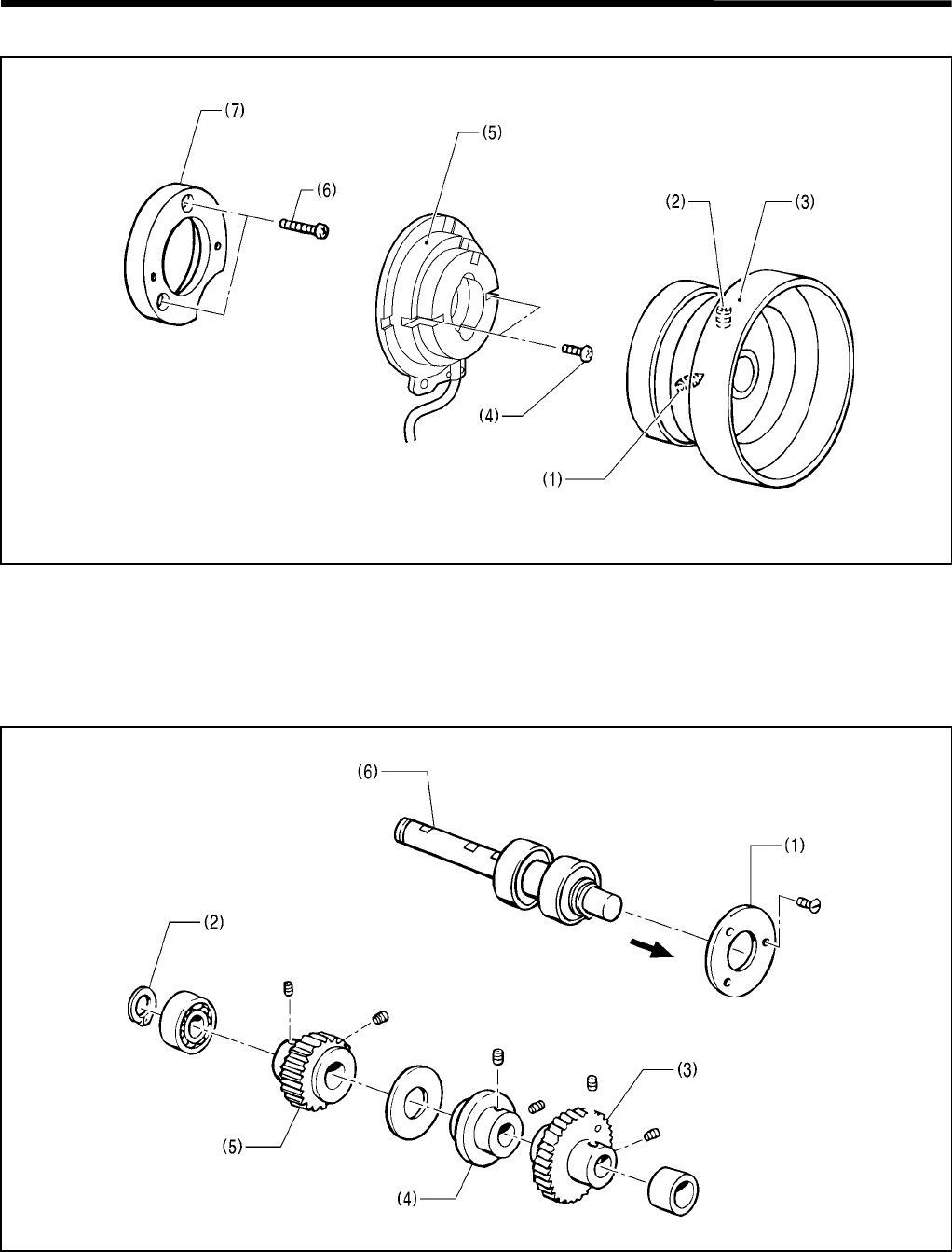
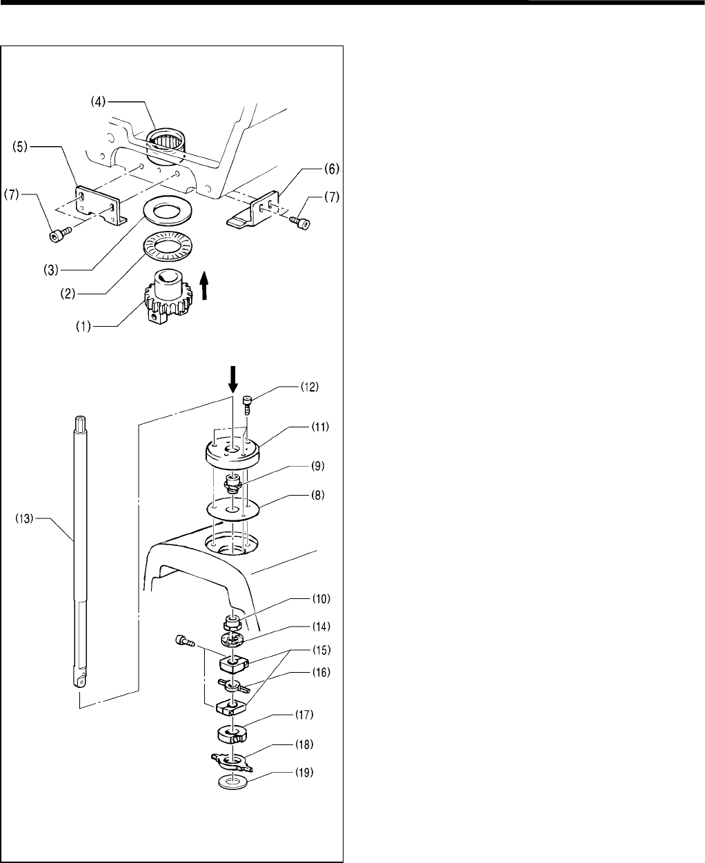
2-1. Covers and work clamp mechanism
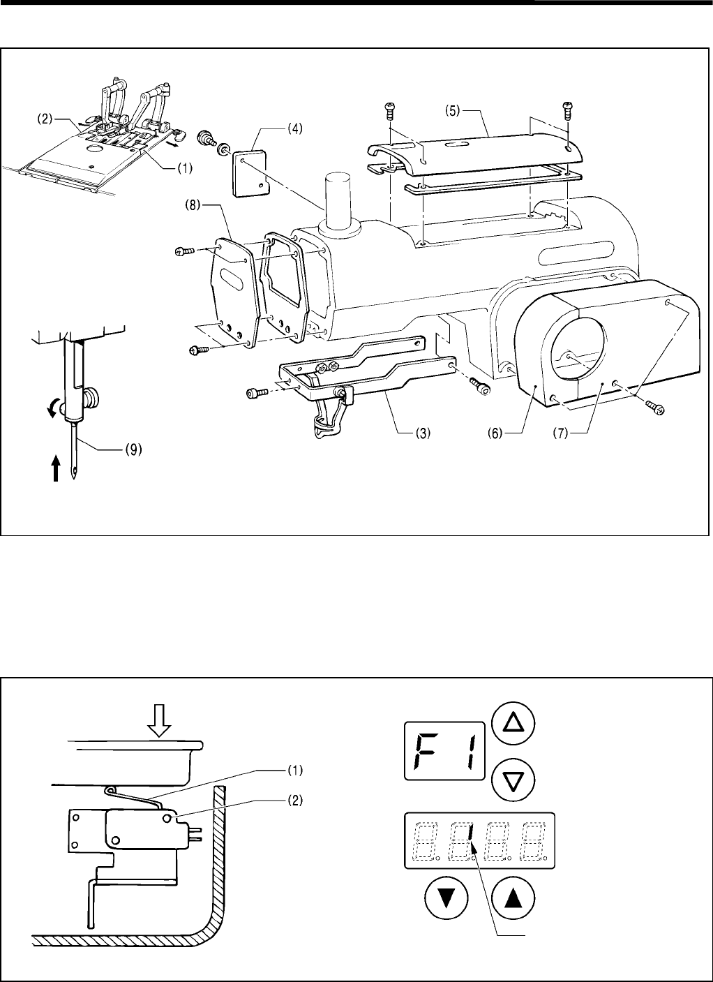
1. Remove the needle (1).
2. Remove the face plate (2), the belt cover F (3), the belt cover R (4), the top cover (5), the zigzag window cover (6),
and the driving needle guard cover (7).
3. Remove the work clamp plates R (8) and L (9).
3694Q 3695Q
3696Q

2. DISASSEMBLY
RH-981A
11
2-2. Feed mechanism
[Feed bracket]
Remove the two Y-feed guide shafts (1) toward you. The feed bracket (2) unit will come off.
[X motor unit]
Remove the motor support (3), which includes the X motor unit.
[Y motor unit]
Loosen the screw (4) of the Y driving shaft holder, pull out the Y-shaft (5) toward you, and remove the Y-feed base
(6), including the Y motor unit.
2-3. Lubrication mechanism
1. Remove the wick supports (1) and (2).
2. Remove the wicks (3) and (4) from the hole.
3. Remove the two screws (5) and wick support L (6).
3697Q 3698Q
3699Q
Hole
Oil tank
2. DISASSEMBLY
RH-981A 12
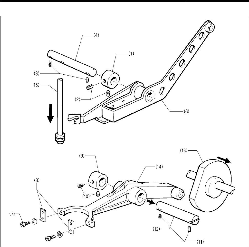
2-4. Looper and spreader mechanisms
1. Loosen the two set screws (2) of the set collar (1), and the two set screws (3), and remove the looper link support
shaft (4).
2. Position the needle at its lower position. Pull the spreader link shaft (5) downward, and remove the spreader cam
lever (6).
3. Remove the two bolts (7) and the looper link springs (8).
4. Loosen the two set screws (10) of the set collar (9) and the two set screws (11), and remove the looper link
support shaft (12).
5. Slide the lower shaft cam (13) in the direction of the arrow, and remove the looper link (14).
3700Q
3701Q
2. DISASSEMBLY
RH-981A
13
2-5. Needle bar rotating mechanism
1. Remove the two bolts (1), then remove the tension pulley U assembly (2) and timing belt U (3).
2. Remove the two bolts (4), then remove the tension pulley D assembly (5) and timing belt D (6).
3. Remove the two screws (7) and the R-sensor setting plate (8).
4. Remove the four bolts (9) and the motor base (10).
5. Loosen the bolt (12) of the vertical shaft T-pulley U assembly (11) and the two set screws (14) of the set collar
(13).
6. Remove the driving looper shaft assembly (15) downward.
3703Q
3702Q
3704Q
3706Q
3705Q
2. DISASSEMBLY
RH-981A 14
2-6. Looper base mechanism
1. Loosen the screw (1), and remove the spreader link shaft (2) in the direction of the arrow.
2. Loosen the screw (3), and remove the looper driving shaft (4) in the direction of the arrow.
3. Remove the tension nut (5), pre-tension spring B (6), the thread guide discs (7), and the L-tension stud (8).
Loosen the screw (10) of the looper pulley assembly (9), and remove the looper base (11) in the direction of the
arrow.
* Be careful not to drop the two ball bearings (12) when removing the looper pulley assembly (9).
3707Q
2. DISASSEMBLY
RH-981A
15
2-7. Needle bar, thread take-up, and zigzag mechanisms
3710Q 3711Q
3709Q3708Q

2. DISASSEMBLY
RH-981A 16
[Needle bar mechanism]
1. Remove the two screws (1), the needle bar guide support plate (2), the two springs (3), the two needle bar guides
(4), and the two washers (5).
2. Loosen the two set screws (6), and remove the two needle bar guide collars (7).
3. Remove the set screw (8), the stud screw (9), the tension spring (10), the needle thread holder plate A (11), and
the guide A (12). Loosen the two bolts (13), and remove the needle bar assembly (14) in the direction of the
arrow.
4. Remove the rubber caps (15) and (16).
5. Loosen the set screw (17), and remove the driving rod pin (18).
6. Loosen the two set screws (19) and the two set screws (21) of the set collar (20), and then pull out the driving
lever shaft (22) in the direction of the arrow.
7. Remove the needle bar driving lever assembly (23).
[Zigzag mechanism]
1. Loosen the bolt (25) of the needle bar block clamp (24), and remove the needle bar block (26) in the direction of
the arrow.
2. Remove the needle bar block clamp (24), the needle bar level feed links (27) and (28), and the needle bar block
collar (29).
3. Remove the rubber cap (30). Loosen the bolt (32) of the needle bar clamp (31), and remove the zigzag lever (33)
in the direction of the arrow.
4. Loosen the bolt (35) of the needle bar block clamp (34), and the bolt (37) of the zigzag crank (36), and remove the
zigzag rock shaft (38) in the direction of the arrow.
[Thread take-up mechanism]
1. Remove the spring (39) and the two rubber caps (40).
2. Loosen the two set screws (41) and the two set screws (43) of the set collar (42), and remove the support shaft
(44).
3. Remove the thread take-up lever assembly (45).
2. DISASSEMBLY
RH-981A
17
2-8. Knife pipe assembly
1. Remove the two screws (1).
2. Remove the knife pipe assembly (2).
2-9. Lower shaft mechanism
Before removing the cam shaft, loosen the timing belt, referring to “3-4-1. Adjusting the timing belt”.
1. Loosen the two set screws (2) of the lower shaft tension pulley assembly (1).
2. Loosen the two set screws (4) of the lower shaft cam (3).
3. Loosen the two set screws (6) of the set collar (5).
4. Remove the cam shaft (7) in the direction of the arrow.
3712Q
3713Q
2. DISASSEMBLY
RH-981A 18
2-10. Synchronizer mechanism
1. Loosen the two set screws (1) and (2), and remove the pulley assembly (3).
2. Loosen the two screws (4), and remove the synchronizer assembly B (5).
3. Remove the two screws (6), and the NP support bracket B (7).
2-11. Upper shaft mechanism
1. Remove ball bearing cap S (1) and the retaining ring (2).
2. Loosen each set screw (2 each) of the needle bar gear (3), the zigzag cam (4), and the upper shaft tension pulley
assembly (5).
3. Pull the upper shaft (6) in the direction of the pulley to remove it. The upper shaft unit will come off.
3714Q
3715Q
2. DISASSEMBLY
RH-981A
19
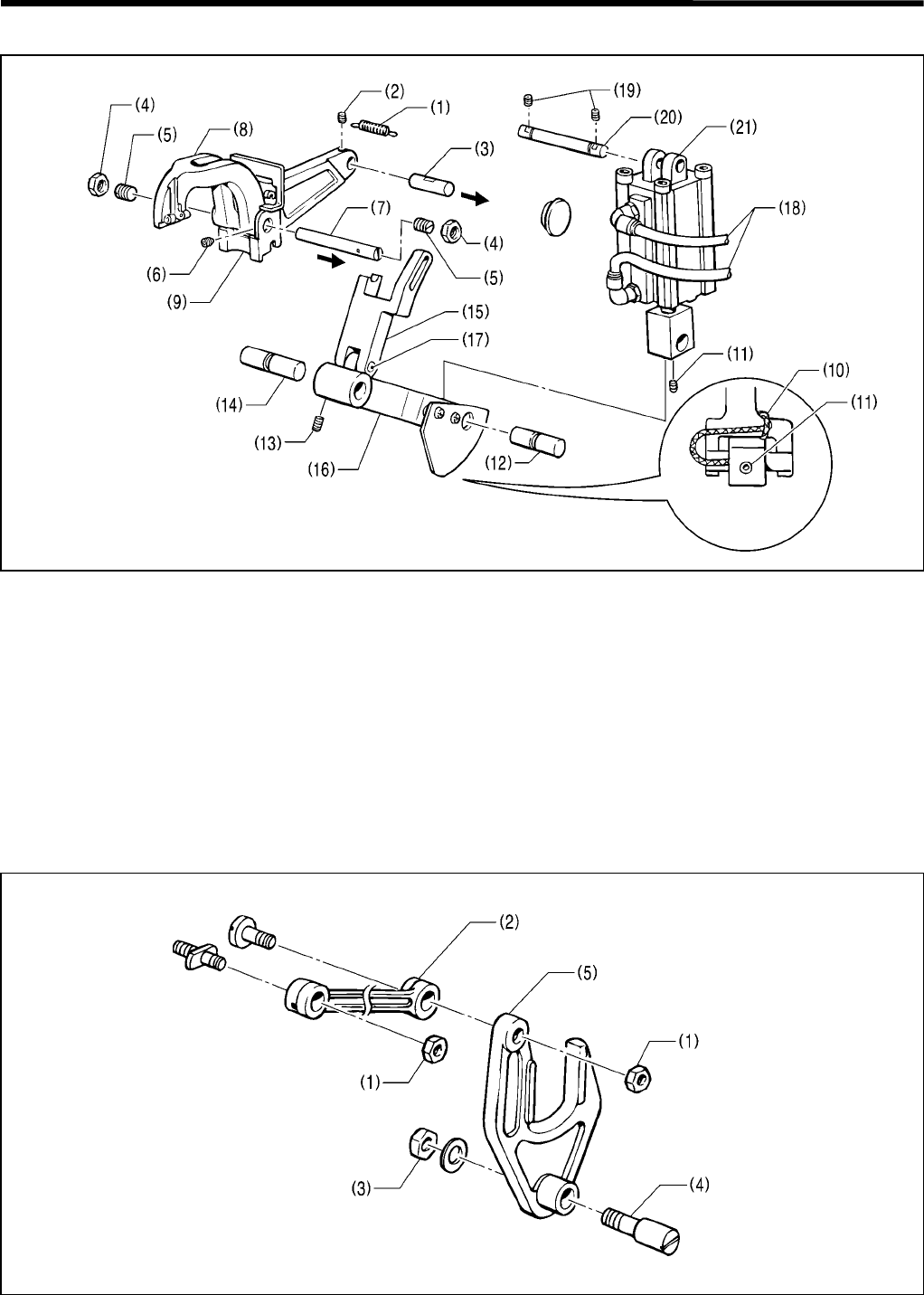
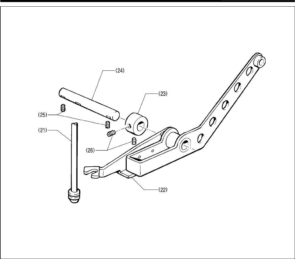
2-12. Cutter mechanism
1. Remove the extension spring (1), loosen the set screw (2), and remove the link shaft B (3) in the direction of the
arrow.
2. Remove the two nuts (4) and the two support screws (5).
3. Loosen the set screw (6), and remove the cutter lever shaft (7) in the direction of the arrow, and the cutter lever
(8) along with the knife lever cover (9).
4. Remove the wick (10), and loosen the set screw (11). Remove the cylinder rod shaft (12).
5. Loosen the set screw (13), and remove the link shaft A (14), and the combination of link A (15), link C (16), and
link shaft C (17) downward.
6. Remove the two air tubes (18).
7. Loosen the two set screws (19), and remove the cylinder support shaft (20) and the cutter cylinder (21).
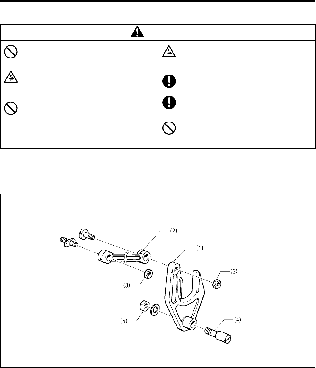
2-13. Zigzag fork mechanism
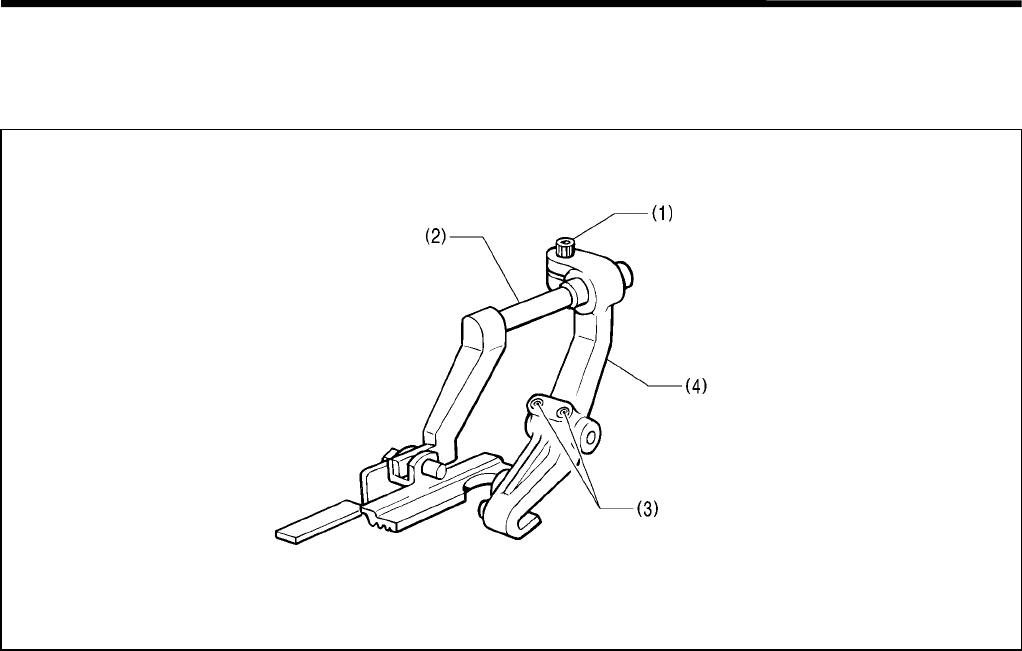
1. Remove the two nuts (1), and the zigzag connection rod assembly (2).
2. Remove the nut (3), the zigzag fork support pin (4), and the zigzag fork (5).
3716Q
Seen from below
3717Q
3. ASSEMBLY
RH-981A 20
3. ASSEMBLY
CAUTION
Assembly should only be carried out by a
qualified technician.
Turn off the power switch before assembly,
otherwise the machine may operate if the start
switch is pressed by mistake, which could result
in injury.
Be sure to wear protective goggles and gloves
when handling the lubricating oil and grease, so
that they do not get into your eyes or onto your
skin, otherwise inflammation can result.
Furthermore, do not drink the oil or eat the
grease under any circumstances, as they can
cause vomiting and diarrhea.
Keep the oil out of the reach of children.
Disconnect the air hoses from the air supply
and wait for the needle on the pressure gauge
to drop to “0” before disassembly of any parts
which use the pneumatic equipment.
Use only the proper replacement parts as
specified by Brother.
If any safety devices have been removed, be
absolutely sure to re-install them to their
original positions and check that they operate
correctly before using the machine.
Any problems in machine operation which
result from unauthorized modifications to the
machine will not be covered by the warranty.
If assembly is not performed in the correct order, it may be hard to attach parts. Assemble as follows.
The following is the main points of assembly.
3-1. Zigzag fork mechanism
1. Combine the zigzag fork (1) and the zigzag connecting rod assembly (2) using the two nuts (3). Insert the zigzag
fork support pin (4) into the hole in the zigzag fork (1), and put them into the arm from above.
2. Insert the zigzag fork support pin (4) into the hole in the side of the arm, and secure it using the nut (5).
3718Q
3. ASSEMBLY
RH-981A
21
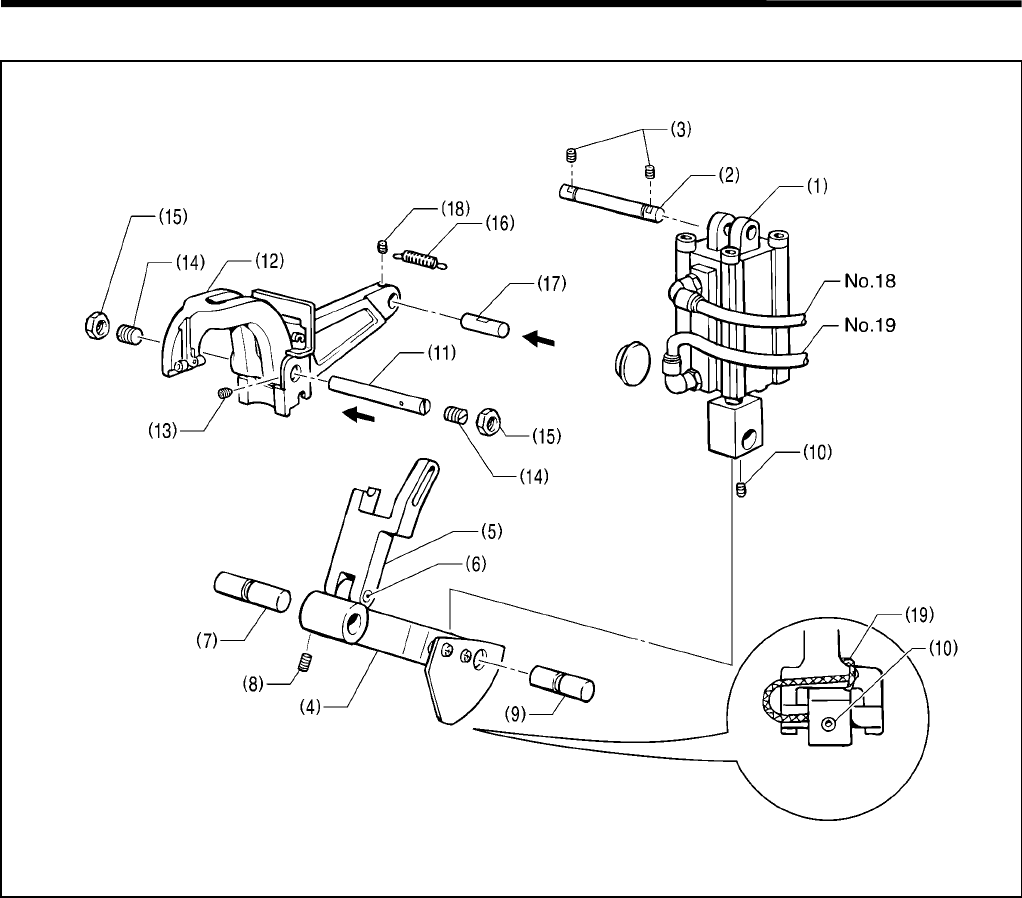
3-2. Cutter mechanism
1. Put the cutter cylinder (1) into the arm with the joints facing the front. Insert the cylinder support shaft (2) into the
hole in the cutter cylinder (1), and secure it using the two set screws (3).
2. Attach No.18 air tube to the upper tube, and No.19 air tube to the lower tube of the cutter cylinder (1).
3. Combine link C (4), link A (5), and link shaft C (6). Position them in the bed from below, and attach link shaft A (7)
to them using the set screw (8).
4. Attach the cylinder rod shaft (9) with the lubrication hole facing the left to the link C (4) and the cylinder rod, and
secure it using the set screw (10).
5. Insert the cutter lever shaft (11) with its slit facing the right, into the hole in the bed, the cutter lever (12), and the
hole in the bed, and tighten the set screw (13) on the screw flat of the cutter lever shaft (11).
6. Tighten the two support screws (14) on each end of the cutter lever shaft (11), and secure it using the two nuts
(15).
7. Hook the extension spring (16) over the cutter lever (12) and the tab of the bed.
8. Pass link shaft B (17) with its slit facing the right, through the slot of link A (5), and the hole in the cutter lever (12),
and tighten the set screw (18).
9. Wind the wick (19) around the right of link C (4), and insert the end of the wick into the lubrication hole in the
cylinder rod shaft (9).
3719Q
Seen from below
3. ASSEMBLY
RH-981A 22
3-3. Upper shaft mechanism
1. Insert the upper shaft (1) into the arm from the right, and place the upper shaft collar (2), the needle bar gear (3),
the zigzag cam (4), the thrust washer (5), the upper shaft tension pulley assembly (6), and the timing belt on it.
* The emergency stop switch cord should be routed above the upper shaft.
2. Position the zigzag fork so that the zigzag cam (4) is between the arms.
3. Attach the ball bearing cap S (7) using the three flat screws (8).
4. Place the ball bearing (9) on the upper shaft, and secure it using the retaining ring (10).
5. Lightly press the needle bar gear (3) and the zigzag cam (4) toward the pulley so that the ball bearing (12) is
pressed between the retaining ring (11) and the upper shaft collar (2).
Tighten the set screw which comes first when the shaft is rotated in the rotation direction, against the screw flat.
6. Position the zigzag fork between the zigzag cam (4) and the thrust washer (5) so that there is no play between
them, face the screw flat to the front, and secure the upper shaft tension pulley assembly (6) by tightening the set
screw which comes first when rotated in the rotation direction, against the screw flat. Then tighten the other set
screw.
7. Temporarily tighten the pulley with its screw flat facing the front.
3720Q
3. ASSEMBLY
RH-981A
23
3-4. Lower shaft mechanism
1. Fit the two ball bearings into the holes in the bed, insert the lower shaft (1) from the left.
2. Put the timing belt (2), the lower shaft tension pulley assembly (3), the lower shaft cam (4), and the set collar (5),
in this order, on the lower shaft (1), and tighten the two set screws (6) of the set collar (5) so that there is no play
between the parts on the lower shaft (1).
3. Lightly press the lower shaft tension pulley assembly (3) and the lower shaft cam (4) against the left ball bearing,
and tighten the two set screws (7) of the lower shaft cam (4).
* The screw flat should align with the set screw which comes first when the lower shaft is rotated in the rotation
direction.
4. When the screw flat of the upper shaft is at the top, and the two set screws (8) of the lower shaft tension pulley
assembly (3) are as shown in figure 1, loop the timing belt over the lower shaft tension pulley assembly (3).
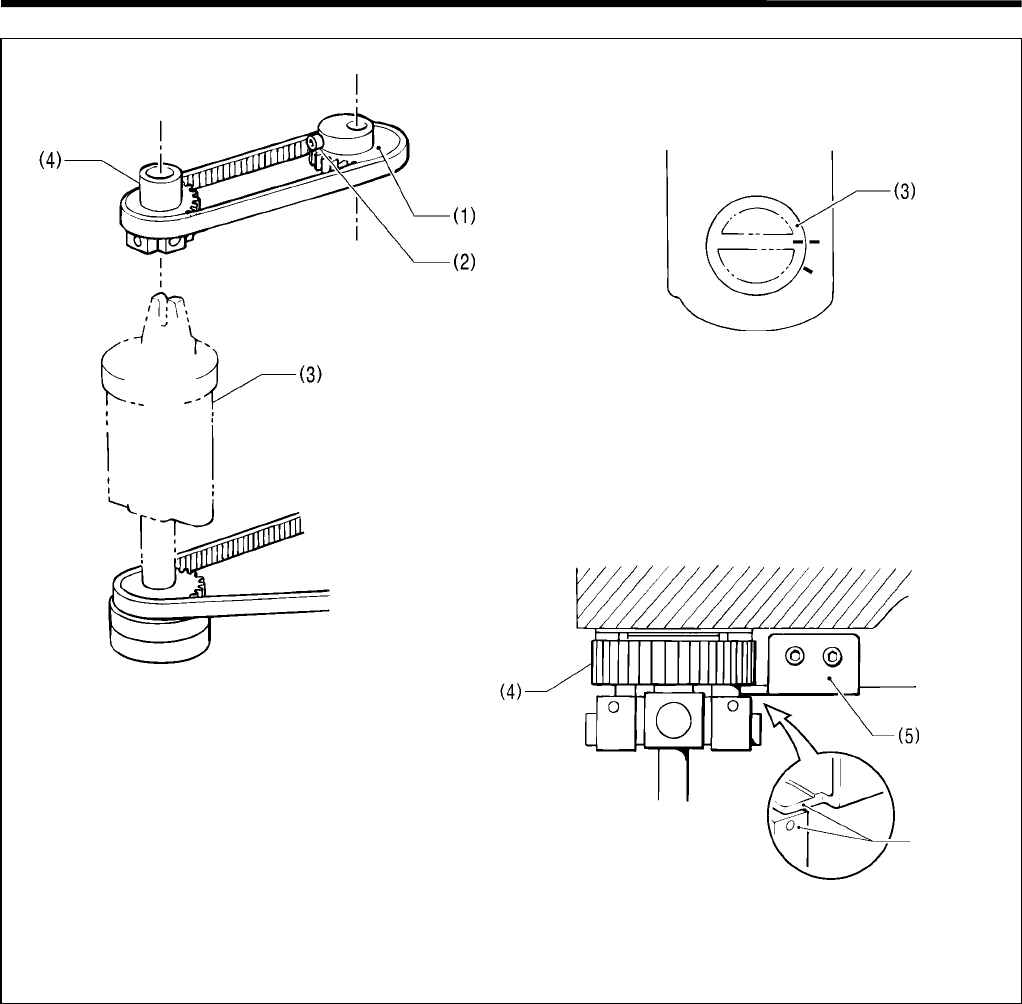
3-4-1. Adjusting the timing belt
Use a screwdriver or similar tool to press the notch of
the tension pulley arm assembly (1) with a force of 39.2
N, and attach the tension pulley assembly.
3722Q
<Figure 1>
3723Q
3721Q
3. ASSEMBLY
RH-981A 24
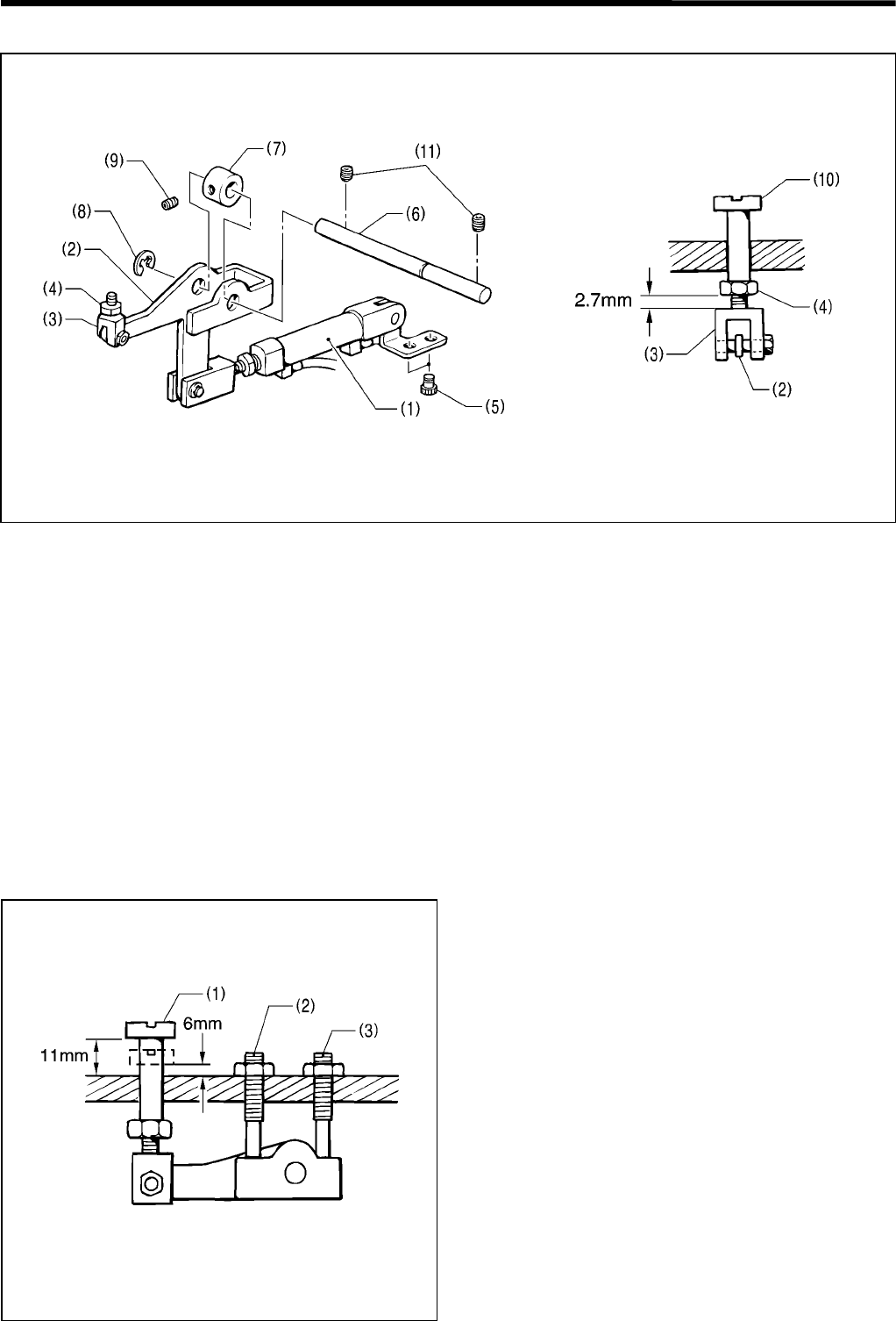
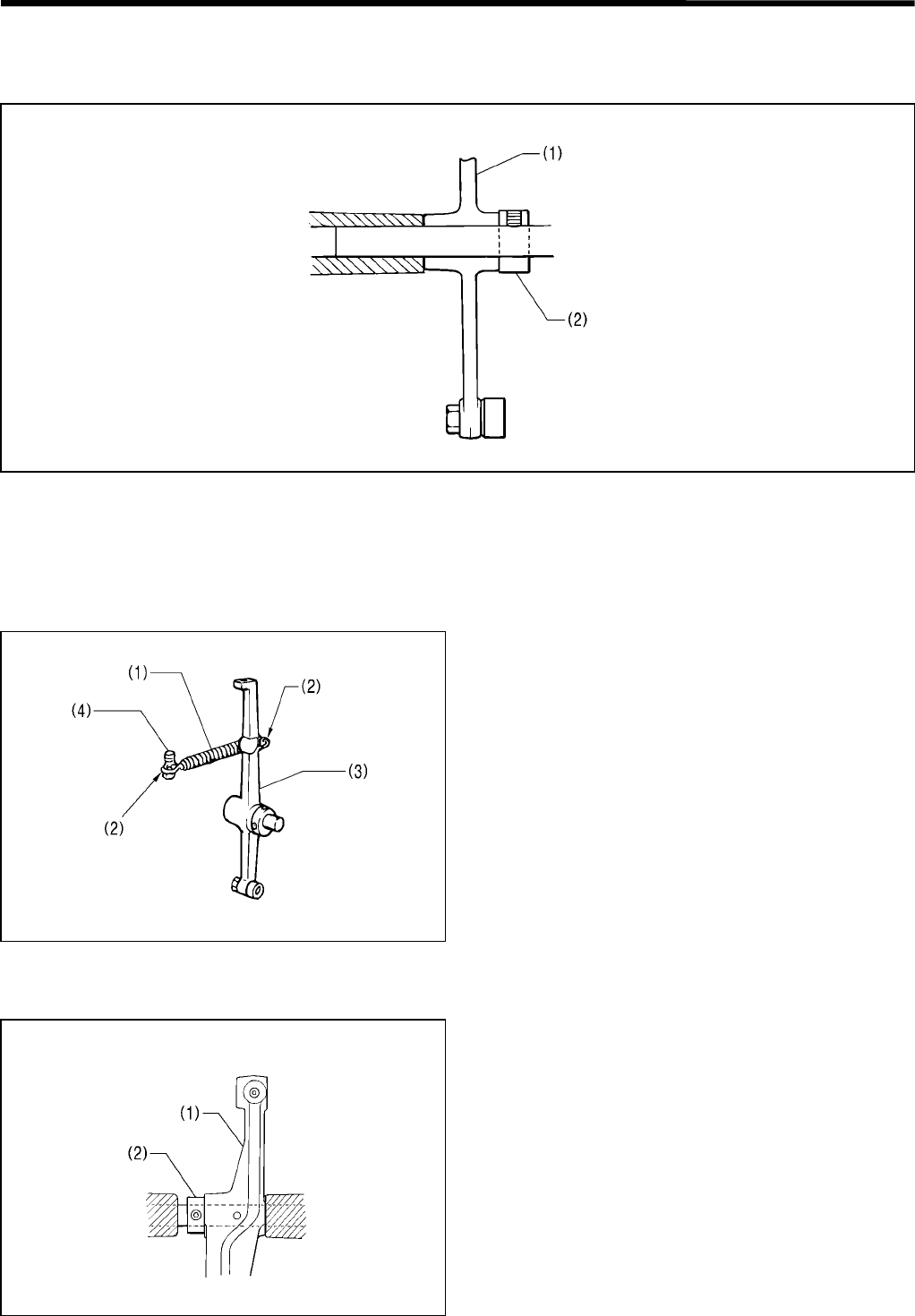
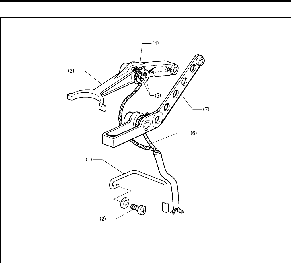
3-5. Upper thread trimmer mechanism
1. Assemble the thread trimmer lever (2), the adjust screw (3), and the nut (4), and attach them to the cylinder 10 X
15 assembly (1). Insert them into the tubular part of the bed, and temporarily tighten the two bolts (5).
2. Insert the thread trimmer lever shaft (6) into the hole in the bed, and pass it through the thread trimmer lever (2)
and the set screw collar (7).
3. Secure the thread trimmer lever (2) using the retaining ring (8) and the set screw collar (7), and tighten the set
screw (9).
4. Insert the thread trimmer lever hammer (10) into the hole in the bed, and tighten the adjusting screw (3) and the
nut (4), until there is 2.7 mm between the nut and the head of the adjusting screw (3).
5. Manually move the thread trimmer lever hammer (10) up and down, and tighten the two set screws (11) where the
thread trimmer lever hammer (10) motion is the smoothest.
6. In the same way, move the thread trimmer lever hammer (10) up and down manually, and tighten the two bolts (5)
where the thread trimmer lever hammer (10) motion is the smoothest.
3-5-1. Adjusting the thread trimmer lever hammer stroke
1. Raise the thread trimmer lever hammer (1), and
adjust the set screw (2) so that the clearance with the
bed is 11 mm.
2. Lower the thread trimmer lever hammer (1), and
adjust the set screw (3) so that the clearance with the
bed is 6 mm.
3724Q 3725Q
3726Q
3. ASSEMBLY
RH-981A
25
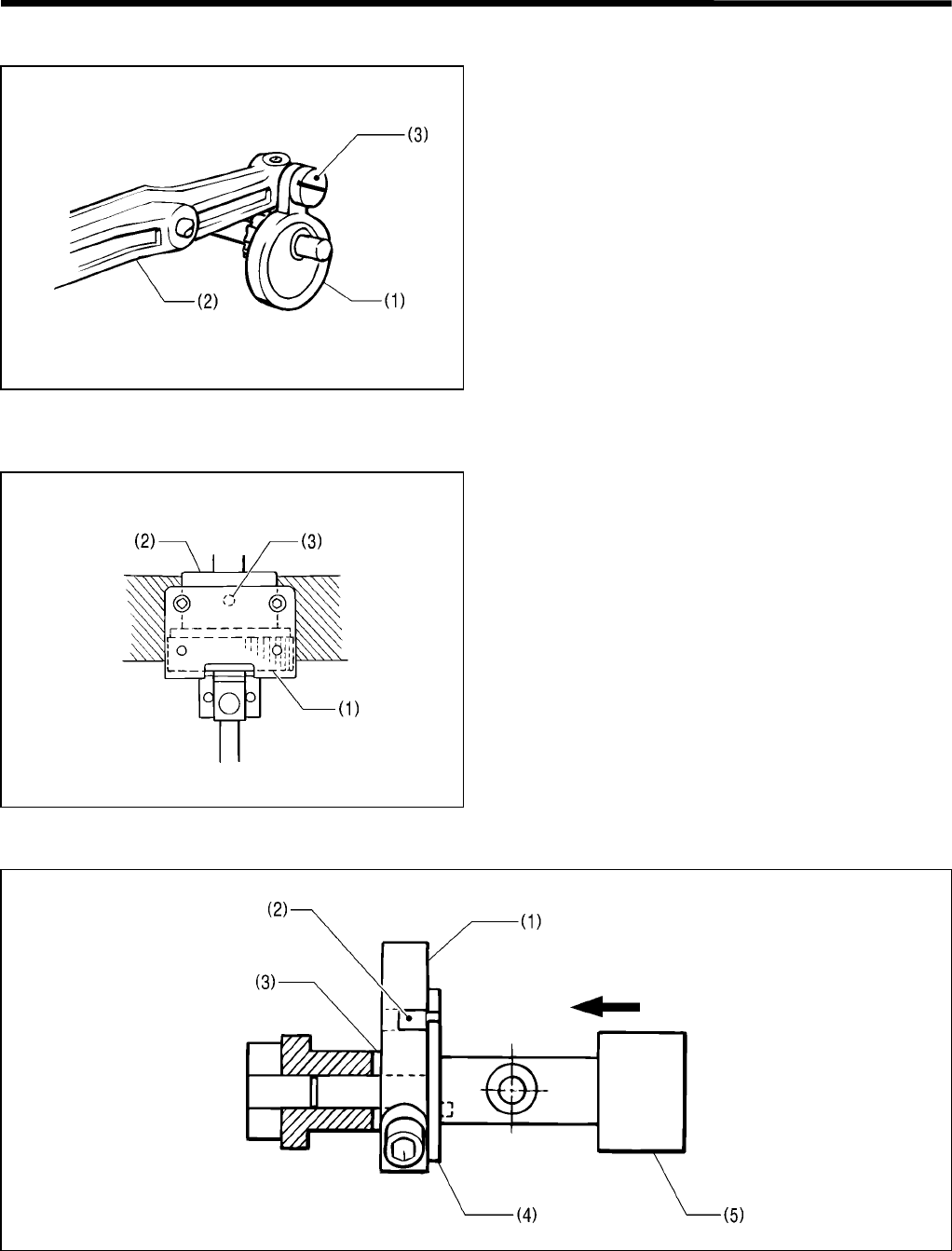
3-6. Knife pipe and the knife bracket
Knife pipe
Insert the knife pipe assembly (1) into the bed from
below, and secure it using the two screws (2).
Knife bracket
Insert a bar with a diameter of 4 mm into the hole (1) in
the knife bracket to fix the knife bracket position, and
tighten the bolts (2) to (6).
3727Q
3728Q
3. ASSEMBLY
RH-981A 26
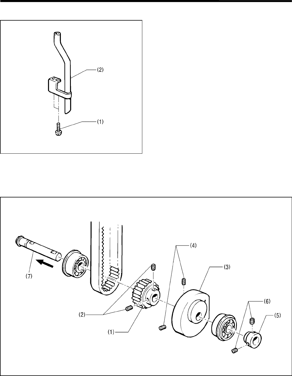
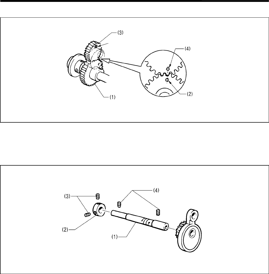
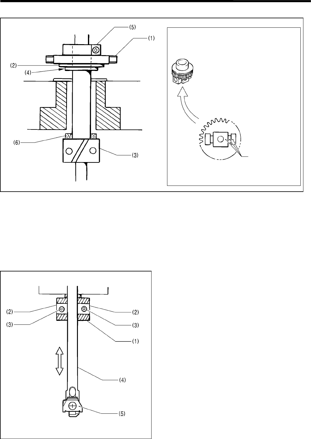
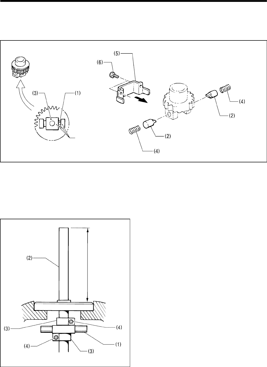
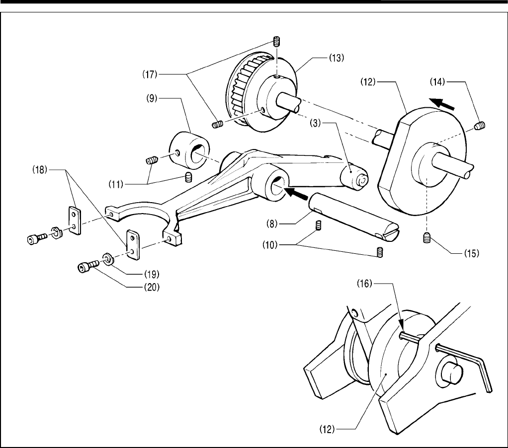
3-7. Driving gear shaft mechanism
Assembling the needle bar gear and the driving rod gear
Engage the needle bar gear (1) with the driving rod gear (3) by matching their identification holes (2) and (4).
Note: Do not mistake the hole (4) for the hole in which the dowel pin is inserted.
Adjusting the set screw collar of the needle bar gear
Tighten the two set screws (3) of the set screw collar (2) with either set screw at the center of the screw flat on the
driving gear shaft (1).
Adjusting the backlash between the needle bar gear and the driving gear
1. The driving gear shaft (1) is eccentric. Turn it to adjust the backlash.
* The driving gear shaft (1) should be turned in the direction where its lubrication hole is moving upward.
2. While pressing the set screw collar (2) toward the pulley so that the driving gear shaft (1) has no end play, tighten
the two set screws (4).
3729Q
Dowel pin
3730Q
3. ASSEMBLY
RH-981A
27
3-8. Needle bar, thread take-up, and zigzag mechanisms
3-8-1. Eliminating end play of the thread take-up on the arm
Eliminate end play of the thread take-up lever (1) on the arm by placing it between the end of the arm and the set
screw collar (2).
3-8-2. Applying grease to the ends of the thread take-up spring
1. Apply grease to the ends (2) of the thread take-up
spring (1).
2. Apply grease to the ends of the thread take-up lever
(3) and the spring hook (4).
3-8-3. Eliminating end play of the needle bar driving lever
Adjust the position of the set screw collar (2) to
eliminate end play of the needle bar driving lever
assembly (1).
3731Q
3732Q
3733Q
3. ASSEMBLY
RH-981A 28
3-8-4. Eliminating end play of the driving rod
The driving rod assembly (1) is attached to the needle
bar driving lever assembly (2) and the pin (3). The
eccentric wheel of the driving rod assembly (1) is free in
the thrust direction.
Place the driving rod assembly (1) between the edge of
the needle bar driving lever assembly (2) and the head
of the pin (3) to eliminate end play of the driving rod
assembly (1).
3-8-5. The strength to tighten the set screw of ball bearing 25/20
The set screw (3) of ball bearing 25/20 (2) for the needle
bar gear (1) should be tightened as little as possible. If it
is tightened excessively, unnecessary load may be
applied to the needle bar gear (1), causing pulse motor
R to go out of control.
* Be sure to apply the screw lock to the circumference
of ball bearing 25/20 (2) before press fitting it.
3-8-6. Eliminating end play of the zigzag rock shaft
Insert the zigzag eccentric pin (2) into the zigzag crank (1), attach the washer (3) and the needle position control
plate assembly (4) as shown in the above figure, and pass the zigzag rock shaft (5) through the arm from the right.
At this time, insert a wedge or similar tool into the split of the zigzag crank (1) for easier adjustment.
Note: Do not fail to attach the washer (3).
3734Q
3735Q
3736Q
3. ASSEMBLY
RH-981A
29
3-8-7. Eliminating end play of the zigzag lever
1. Adjust the needle bar clamp (3) so that there is no
end play of the zigzag lever (2) which is connected to
the zigzag rock shaft (1).
The zigzag lever (2) should rotate easily in the
rotation direction.
2. Pass the wick (4) through the zigzag lever (2), and fit
the cap (5).
3. Attach the needle bar level feed link (6) to the zigzag
lever (2) vertically, and turn it 90°.
3-8-8. Attaching the needle bar yoke and the needle bar level feed link
1. Combine the needle bar driving lever assembly (1)
and the needle bar yoke (2), pass the wick (3)
through the needle bar driving lever assembly (1),
and fit the cap (4).
2. Attach the needle bar level feed link (5) to the needle
bar yoke (2) vertically, and turn it 90°.
3737Q
3738Q
3. ASSEMBLY
RH-981A 30
3-8-9. Attaching the needle bar bush U and the needle bar
1. Put the thrust bearing (2) and the thrust washer (3) on
the needle bar gear (1). Attach them to bearing 25/20
(4), and secure them using gear supports A (5) and B
(6) and the screws (7) so that the needle bar gear (1)
can turn easily but without any end play.
* Do not forget to attach timing belt U.
2. Insert the plate spring (8) into the hole in the arm, and
bind it using needle bar bush U (9) and the needle
bar bush nut U (10).
3. Temporarily attach holder base B (11) using the three
bolts (12).
4. Pass the needle bar assembly (13) through the arm
from above.
5. Insert the needle bar felt (14), the needle bar clamp
(5), the needle bar level feed link (16), the needle bar
block clamp (17), the needle bar level feed link (18),
and the needle bar block collar (19), through the
needle bar assembly (13) in this order.
3739Q
3740Q
3. ASSEMBLY
RH-981A
31
3-8-10.Eliminating end play of the needle bar block
Adjust the positions of the needle bar level feed link (1) and the needle bar block collar (2) using the flange (4) of the
needle bar block (3) and the needle bar block clamp (5), so that there is no end play.
Note: Be sure to insert the needle bar block felt (6).
3-8-11.Adjusting the needle bar in the radial direction
Insert the two needle bar guide collars (2) into the
needle bar block (1), and adjust the position of the
needle bar assembly (4) using the two set screws (3) so
that the needle bar can move smoothly.
Note: Position the needle bar assembly (4) so that the
holder plate A (5) will face the front when the set
screws (3) are facing the front.
When assembling the needle bar block and
the needle bar gear, align their white paint
marks with each other.
3741Q 3742Q
White paint marks
3743Q
3. ASSEMBLY
RH-981A 32
3-8-12.Attaching the needle bar block assembly
The needle bar block assembly is a set of the needle bar gear, the needle bar block, and the washers.
When disassembling and then reassembling the needle bar block assembly, align the white marks of the needle bar
gear, the needle bar block, and the collars with each other.
1. Insert the two needle bar guides (2) into the hole in the needle bar block (3) on each side, taking care of the white
paint mark of the washer (1).
2. Attach the two spring (4) using the needle bar guide support plate (5), and tighten the two screws (6).
3-8-13.Adjusting the height of the needle bar
1. Turn the pulley to set the needle bar level feed link (1)
at its highest position.
2. Set the height of the needle bar (2) to approx. 62 mm,
eliminate end play between the two needle bar
clamps (3) and the needle bar level feed link (1), and
tighten the two screws (4).
3745Q
3744Q
White paint marks
Approx. 62 mm
3746Q

3. ASSEMBLY
RH-981A
33
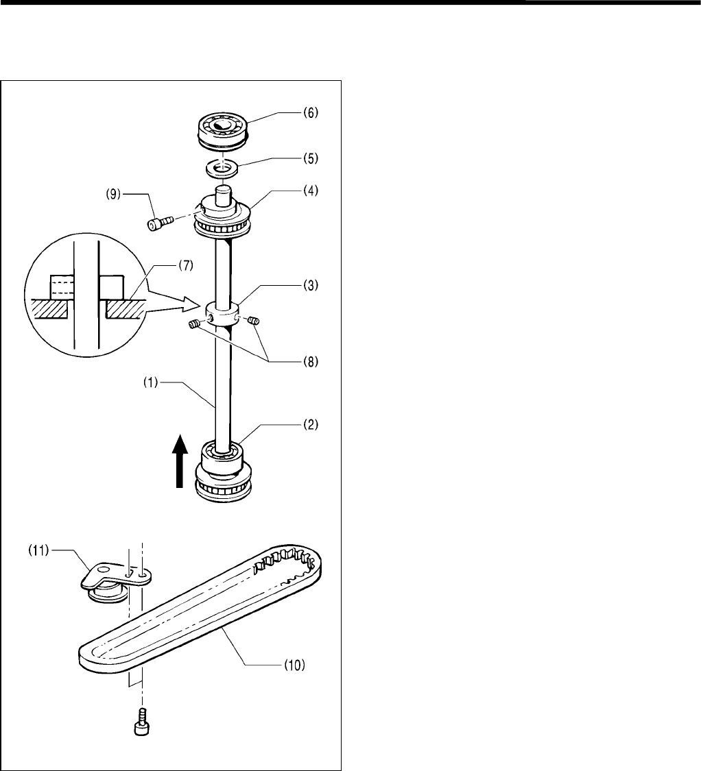
3-9. Looper base
1. Insert the shaft of the looper base (1) through the hole in the bed, attach the two ball bearings (2) and the looper
pulley (3) to the shaft of the looper base (1) so that there is no end play, and tighten the screw (4).
2. Insert the looper driving shaft (5) into the shaft of the looper base (1), then the looper link clamp (6) into the looper
driving shaft (5), and tighten the screw (7).
3. Insert the spreader link shaft (8) into the hole in the looper driving shaft (5), then the spreader link base (9) into the
spreader link shaft (8). Align the reference line (10) with the top surface of the spreader link base (9), and tighten
the screw (11).
4. Attach the L-tension stud (12), the thread guide discs (13), pre-tension spring B (14), and the tension nut (15) to
the looper base (1).
3747Q
3. ASSEMBLY
RH-981A 34
3-10. Needle bar rocking mechanism
3-10-1.Driving looper shaft
1. Insert the driving looper shaft assembly (1) through
the hole in the bed from below, place the ball bearing
(2), the set screw collar (3), the vertical shaft T-pulley
U assembly (4), the washer (5), and finally the ball
bearing (6) on the driving looper shaft assembly (1).
2. Set the clearance between the set screw collar (3)
and the bed (7) to 0.02 – 0.03 mm in the thrust
direction, and tighten the two set screws (8).
3. Press the vertical shaft T-pulley U assembly (4) and
the washer (5) against the ball bearing (6), and
tighten the screw (9).
* Be sure to pass the driving looper shaft assembly
(1) through timing belt U (10).
4. Attach the tension pulley arm U assembly (11) while it
is being pulled by a force of 19.6 N.
* Deflection in the center of span: 3 ± 0.5 mm when
4.9 N is applied.
3749Q
3748Q
3. ASSEMBLY
RH-981A
35
3-10-2. Needle bar rocking mechanism
Adjusting the positional relationship between the needle rotation pulley assembly M and the
looper base
1. Align the match mark in the looper base (1) with that in the bed, as shown in the figure.
2. Turn the needle rotation pulley assembly M (2) until the pin (3) makes contact with the motor base.
3. Attach the timing belt.
4. Make sure that the looper base (1) can rotate through 360° easily.
* Tighten the screw of the looper pulley at the front.
Adjusting the timing belt tension
Attach the timing belt D while the tension pulley arm D assembly is being pulled by a force of 68.6 N.
* Deflection in the center of span: 6 ± 0.5 mm when 4.9 N is applied.
3751Q
3750Q
3. ASSEMBLY
RH-981A 36
Adjusting the positional relationship between the looper base and the needle bar gear
1. Loosen the bolt (2) of the vertical shaft T-pulley U assembly (1).
2. Align the match mark in the looper base (3) with that in the bed, as shown in the figure.
3. Orient the needle bar gear (4) in the direction shown in the figure, and align it with gear support B (5).
4. Tighten the bolt (2) of the vertical shaft T-pulley U assembly (1).
3752Q 3754Q
Align
3753Q
3. ASSEMBLY
RH-981A
37
3-11. Looper and spreader machanisms
1. Attach the looper oil guide (1) using the screw (2).
2. Wind the wick (4) around the boss of the looper link (3). Be sure to pass the two wicks (5) under the wick (4).
3. Wind the wick (6) around the spreader driving lever (7), as shown in the figure.
3755Q
3. ASSEMBLY
RH-981A 38
4. Place the looper link (3) and the set screw collar (9) on the looper link shaft (8), and secure the latter using the two
set screws (10).
5. Tighten the two set screws (11) of the set screw collar (9) to eliminate end play.
6. Position the lower shaft cam (12) and the lower shaft tension pulley assembly (13) so that they lightly make
contact, then tighten the screw (14) on the screw flat at the front and another screw (15).
7. Insert an allen wrench (2.5 mm across flats) into the hole in the bed and the hole (16) in the lower shaft cam (12).
Position the screw flat of the upper shaft at the top (where the needle is at its lowest position), and tighten the two
set screws (17) of the lower shaft tension pulley assembly (13).
8. Attach the two plate springs (18) to the looper link (3) using the two spring washers (19) and the two bolts (20).
3757Q
3756Q
3. ASSEMBLY
RH-981A
39
9. Turn the pulley until it comes to its stop position, and attach the spreader link shaft (21) to the forked portion of the
spreader driving lever (22) while pulling the former downward.
10.Pass the looper link support shaft (24) through the spreader driving lever (22) and the set screw collar (23), and
secure them using the two set screws (25). (The split in the shaft should be facing the right.)
11. Tighten the two set screws (26) of the set screw collar (23) to eliminate the end play.
3758Q
3. ASSEMBLY
RH-981A 40
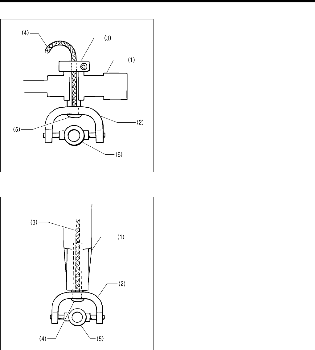
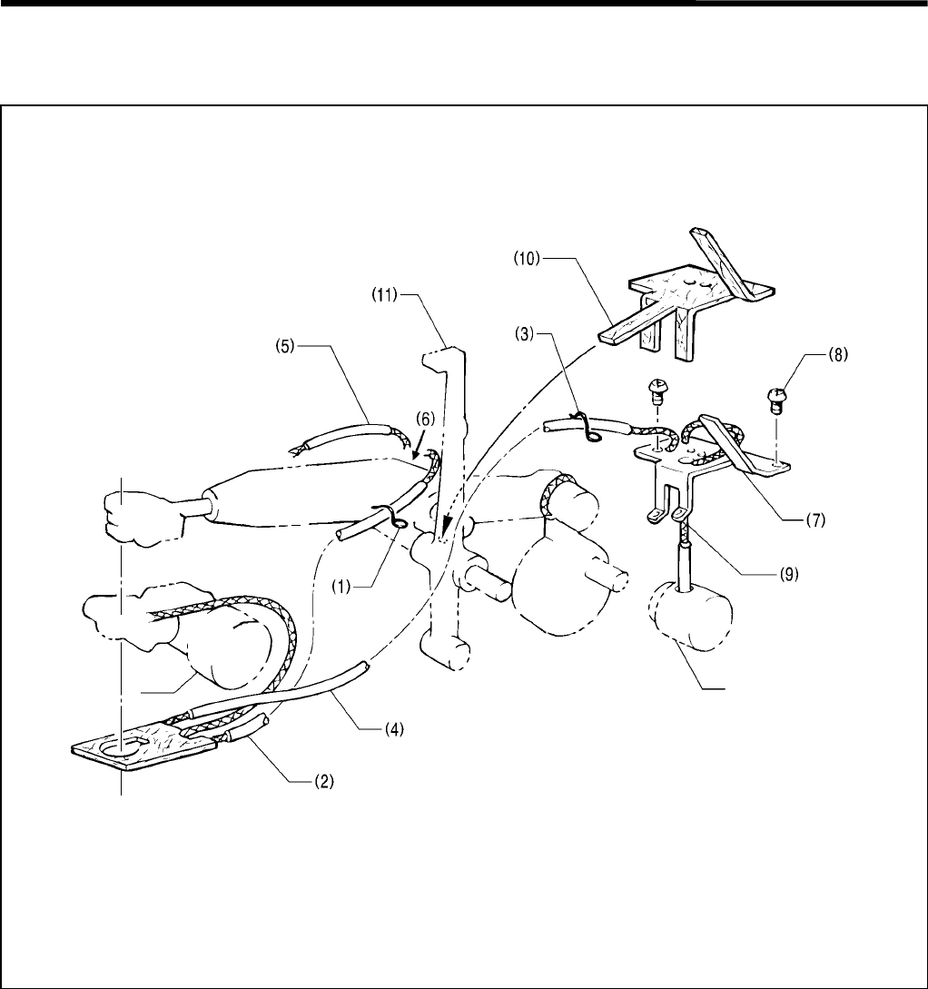
3-12. Lubrication mechanism
3-12-1.Machine head
1. Hold the wick (2) using the cord holder (1).
2. Hold the wick (3) using the cord holder (4).
3. Insert the wicks (2) and (5) into the hole (6).
4. Attach wick support L (7) using the two screws (8).
* At this time, the emergency stop switch cord should be routed above wick support L (7).
5. Using a pair of tweezers, insert the wick (9) into the hole in the oil tank. At this time, insert the oil tube into the hole,
as shown in the figure.
6. Pass the wick (4) under the felt (10).
7. Push the felt (10) into the lubrication hole in the thread take-up lever (11).
3759Q
Oil tank
3. ASSEMBLY
RH-981A
41
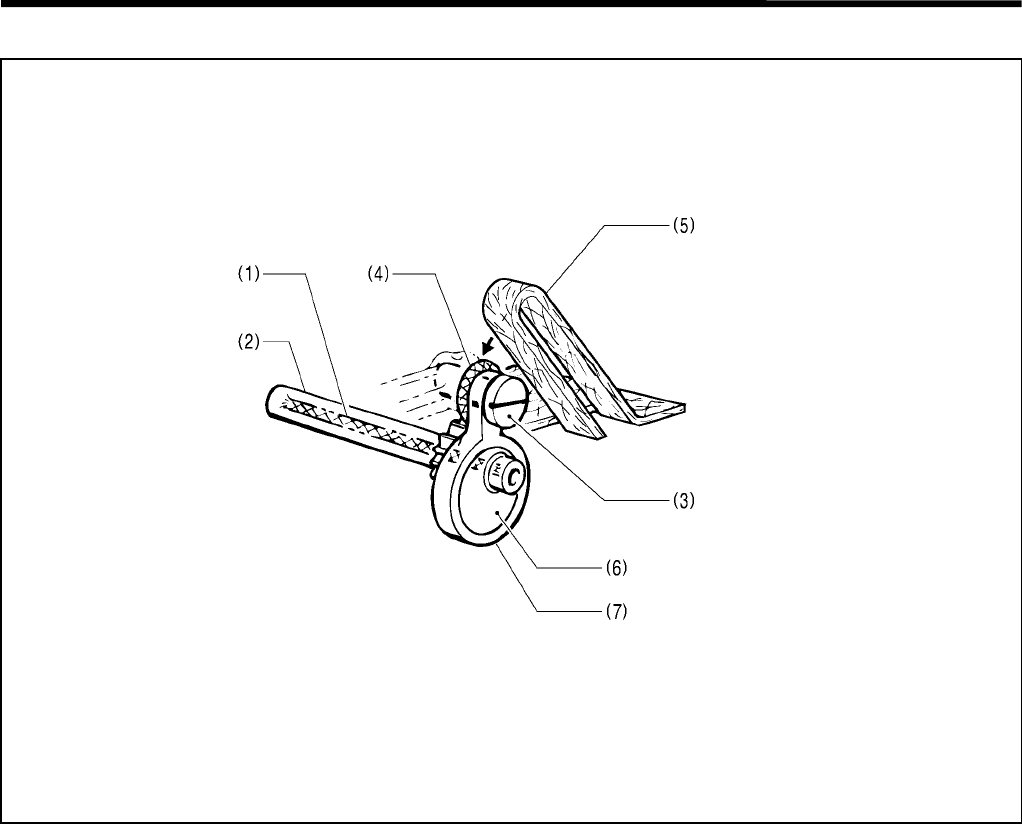
3-12-2. Driving gear shaft
1. Oil is supplied to the driving gear shaft (2) through the wick (1).
2. The wick (4), which is wound around the boss of the pin (3), makes contact with the felt (5), and oil is supplied to
the pin (3), the eccentric wheel (6) and the driving rod (7).
3760Q
3. ASSEMBLY
RH-981A 42
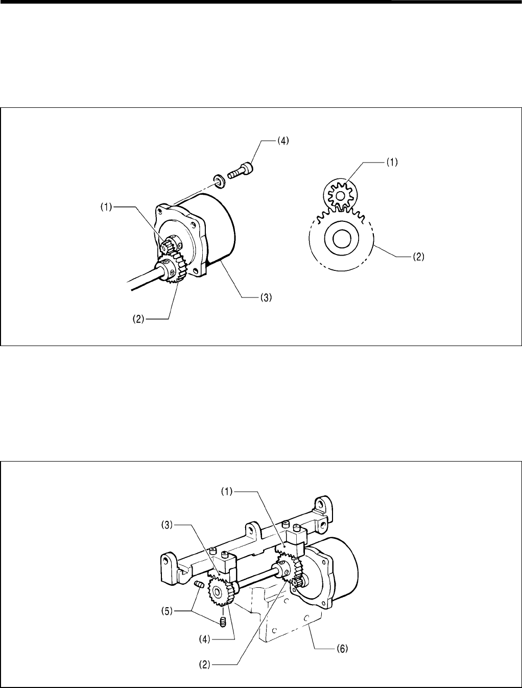
3-13. Feed mechanism
3-13-1.X direction
Adjusting the backlash between the driving gear and the idle gear
Note: Be sure to remove the motor support. Adjustment should be carried out with the driving gear and the idle
gear treated as a unit.
Adjust the backlash between the driving gear (1) and the idle gear (2) when they are engaged, using the weight of
pulse motor X (3) (as shown in the figure above).
Tighten the four bolts (4).
Adjusting the idle gear
Adjust the positions of the X racks and the idle gear
1. Loosen the two set screws (5) of the idle gear (2) to adjust the engagement between the X rack (3) and the idle
gear (4) based on the engagement between the X rack (1) and the idle gear (2).
2. Engage the idle gears (2) and (4) with the X racks (1) and (3), respectively, and attach the motor support (6) while
pressing it.
3. Tighten the two set screws (5) so that there is no end play of the idle gear (4).
3761Q
3762Q
3. ASSEMBLY
RH-981A
43
3-13-2. Y direction
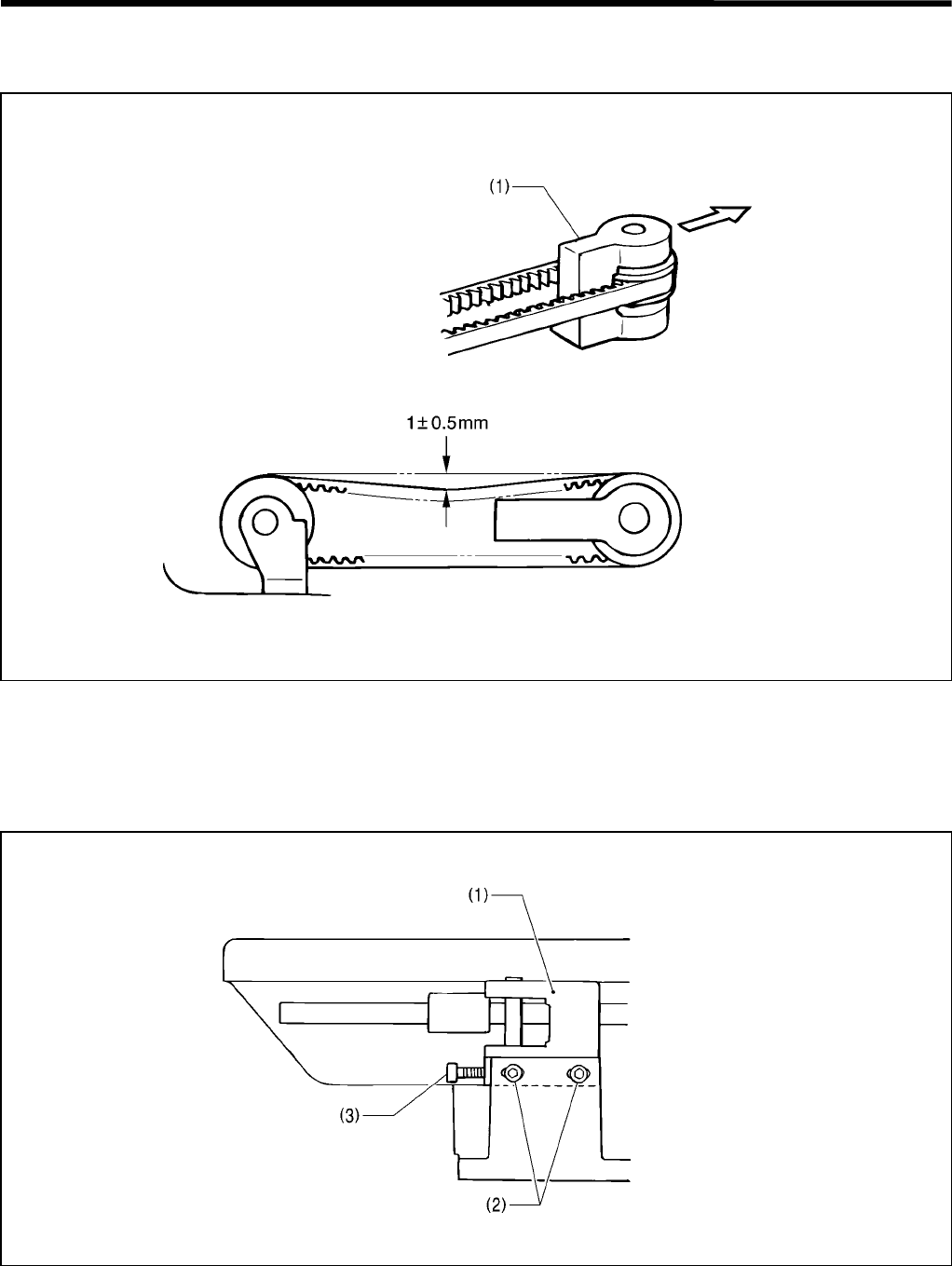
Adjusting the tension of the Y-timing belt
Secure Y-pulley support L (1) while pulling it with a force of 117.6 N.
When the belt deflection is used instead to determine Y-pulley support L (1) position, the deflection will be 1 ± 0.5
mm when the belt is pressed at the center with a force of 4.9 N.
* The belt tension can be adjusted when the Y-feed base is still attached to the bed.
Loosen the two bolts (2) of Y-support L (1), and use the bolt (3) to adjust the belt tension.
The tension in this case should be the same value as that above.
3763Q
3764Q
3. ASSEMBLY
RH-981A 44
Adjusting the position of the Y-driving shaft holder
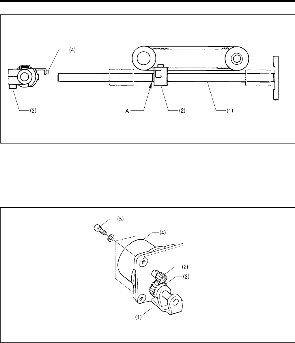
Align the left end of the Y-driving shaft holder (2) with the reference line A of the Y-shaft (1).
* When tightening the bolt (3), the sensor partition plate assembly (4) should face the top.
Adjusting the backlash between the driving gear and the idle gear
Remove the Y-feed base (1). Adjustment should be carried out with the driving gear and the idle gear treated as a
unit.
Adjust the backlash between the driving gear (2) and the idle gear (3) when they are engaged under the weight of
pulse motor Y (4) (as shown in the figure above).
Tighten the four bolts (5).
3766Q
3765Q
3. ASSEMBLY
RH-981A
45
3-13-3.Attaching the X-feed guide shaft
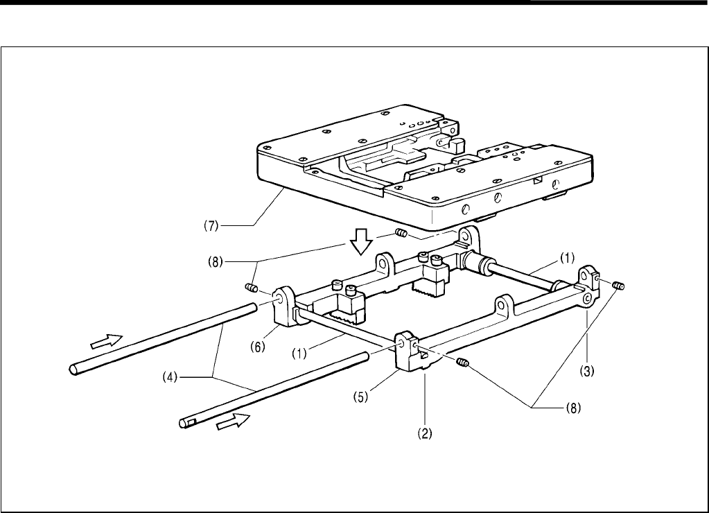
1. Loosen the four bolts (2) and the two set screws (3) of the X-feed guide shaft (1) so that the shaft is still
temporarily held in place.
2. Insert the Y-feed guide shafts (4) into the X-feed shaft holder R (5) and the X-feed shaft holder L assembly (6)
and the feed bracket (7), and tighten the four set screws (8).
3. Move the feed bracket (7) in the X direction a few times.
4. Tighten the four bolts (2) and the two set screws (3).
3767Q
3. ASSEMBLY
RH-981A 46
3-14. Synchronizer
1. Attach the NP support bracket B (1) with its notched portion facing the rear, using the two screws (2).
2. Secure the synchronizer assembly B (3) using the two screws (4).
3. Tighten the set screw (5) in the V-groove in the upper shaft, and attach the pulley assembly (6). Then tighten
another set screw (7).
* The set screw (5) should be tightened in the front hole which comes first when the pulley is rotated in the
rotation direction.
4. After attaching the synchronizer, check the machine torque.
3768Q
3. ASSEMBLY
RH-981A
47
3-15. Covers and work clamp mechanism
1. Attach the work clamp plates R (1) and L (2).
2. Attach the driving needle guard cover (3), the zigzag window cover (4), the top cover (5), the belt cover F (6), the
belt cover R (7), and the face plate (8).
3. Attach the needle (9).
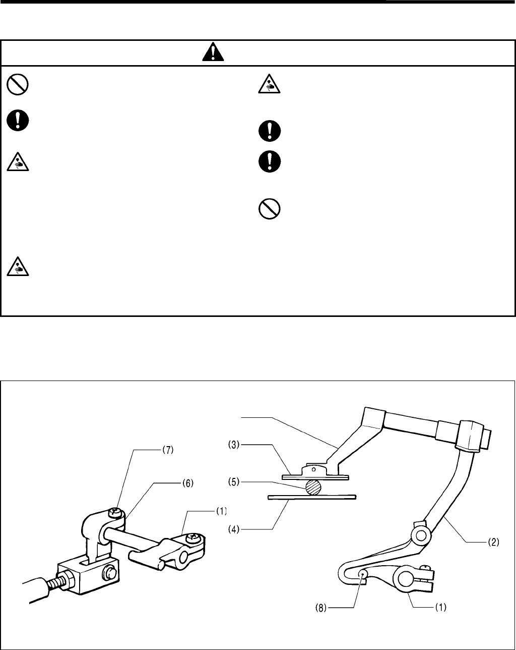
3-16. Safety switch
1. Switch to the input check mode.
2. Adjust the height of the safety switch (1) using the two screws (2) so that the LED does not go off even if the
machine head is lowered and the bed is shaken up and down.
3771Q 3770Q
3769Q
3772Q 3773Q
LED is lit.
4. ADJUSTMENT
RH-981A 48
4. ADJUSTMENT
CAUTION
Maintenance and inspection of the sewing
machine should only be carried out by a
qualified technician.
Ask your Brother dealer or a qualified
electrician to carry out any maintenance and
inspection of the electrical system.
Turn off the power switch and disconnect the
power cord from the wall outlet at the
following times, otherwise the machine may
operate if the start switch is pressed by
mistake, which could result in injury.
• When carrying out inspection, adjustment
and maintenance
• When replacing consumable parts such as
the loopers and knife
Disconnect the air hoses from the air supply
and wait for the needle on the pressure gauge
to drop to “0” before carrying out inspection,
adjustment and repair of any parts which use
the pneumatic equipment.
If the power switch and air need to be left on
when carrying out some adjustment, be
extremely careful to observe all safety
precautions.
Use only the proper replacement parts as
specified by Brother.
If any safety devices have been removed, be
absolutely sure to re-install them to their original
positions and check that they operate correctly
before using the machine.
Any problems in machine operation which result
from unauthorized modifications to the machine
will not be covered by the warranty.
4-1. Adjusting the work clamp lift height
The work clamp lift height is adjusted to 16 mm.
(The lift height includes the clearance between clamp lever B (1) and clamp lever L (R) (2).)
1. Insert the block or the thickness gage (5) between the work clamp L (R) (3) and the needle plate (4).
2. Loosen the screw (7) of the driving lever (6), and put the end (8) of clamp lever B (1) on the end of clamp lever L
(R) (2). Then re-tighten the screw (7).
Note: Make sure that work clamp L (R) (3) securely holds the block or the thickness gage (5).
Make sure that work clamp cylinder is fully extended.
3774Q 3775Q
Clamp arm
4. ADJUSTMENT
RH-981A
49
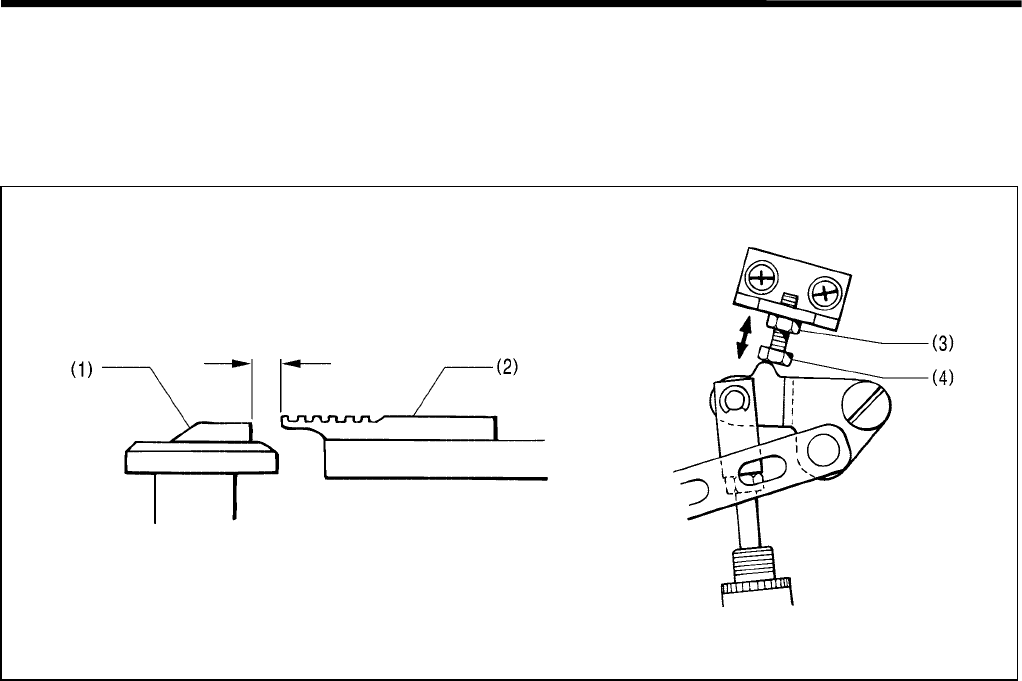
4-2. Adjusting the position of the work clamp plate
Before this adjustment, make sure that adjustment in “4-5. Adjusting the X-axis home position” has been completed.
Adjust so that the throat plate (1) and the needle plate R (2) do not make contact during sewing.
The standard clearance between the throat plate (1) and the needle plate R (2) is 1.3 mm (when the cutting space is
set to 0).
1. Use the parameter settings to set the cutting space to "0".
2. Select the test feed mode, and press the start switch.
3. Keep pressing the start switch, and make sure that the clearance between the throat plate (1) and the needle
plate R (2) is 1.3 mm.
4. If the clearance is not 1.3 mm, loosen the nut (3), and turn the bolt (4) to adjust the clearance.
Note: Adjust the clearance between the throat plate (1) and the needle plate L in the same manner.
* If the maximum stitch width correction amount is set to 2.0 mm, adjust the distance between the throat plate and
the needle plate to more than 2.0 mm.
1.3 mm
3094Q 3095Q
Increase
Decrease
4. ADJUSTMENT
RH-981A 50
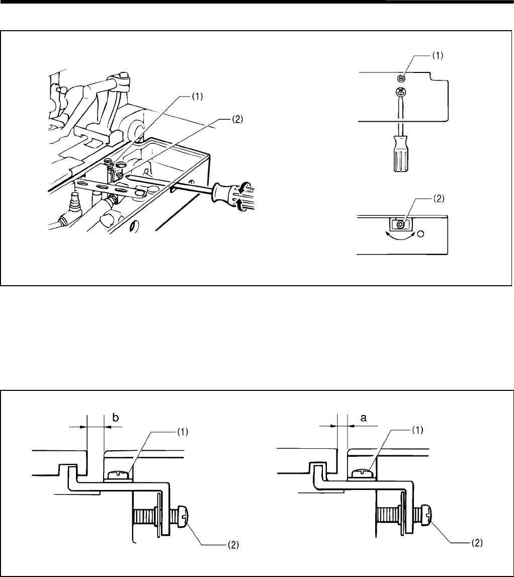
4-3. Adjusting the cloth opening amount
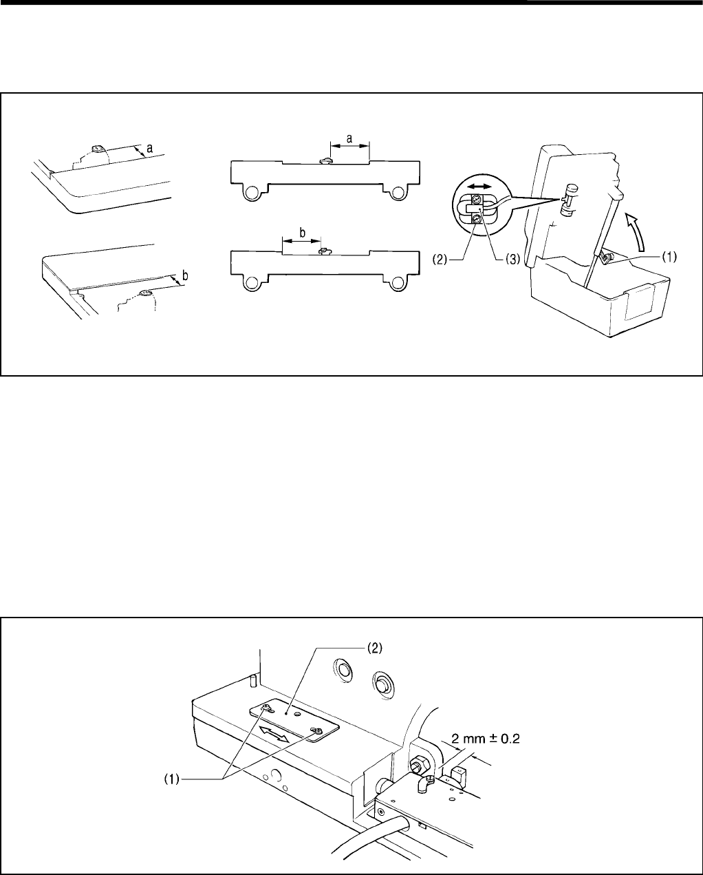
1. Loosen the screw (1), and then insert a screwdriver into the notch in the side of the feed bracket and turn the
adjusting screw (2) to adjust the opening amount.
2. After tightening the screw (1), measure the opening amount.
Note: Adjust so that the opening amounts for the left and right work clamp plates are equal.
* It is usually sufficient for one work clamp plate to open by 0.8 mm.
Measuring the opening amount
1. Switch the mode to test feed mode.
2. Lower the work clamp and then use calipers to measure the distance a.
3. Press the start switch. The feed bracket will move and then the left and right work clamp plates will open.
4. Use calipers to measure the distance b.
5. The difference between a and b is the opening amount. (Opening amount = a - b)
3098Q 3099Q
3096Q 3097Q
4. ADJUSTMENT
RH-981A
51
4-4. Adjusting the position of the work clamp
The back and forth and sideways movement of the work clamp can be respectively adjusted.
The work clamp should be centrally positioned as to the needle movement.
[Back and forth movement]
Loosen the bolt (1), and adjust the position of the clamp arm (2).
[Sideways movement]
Loosen the two screws (3), and adjust the position of the clamp lever (4).
3776Q
4. ADJUSTMENT
RH-981A 52
4-5. Adjusting the X-axis home position
Dimension a (when the looper base is at 0°) and dimension b (when the looper base is at 180°) from the stepped
portion of the throat plate to both edges of the feed bracket must be equal.
1. Set the tacking length to 0 by the parameter settings, and switch to the test feed mode.
2. Remove the work clamp plate, and press the start switch.
3. Move the feed bracket, and measure dimensions a and b.
4. If dimensions a and b are not equal, turn off the power.
5. Raise the machine head, secure it using the head support lever (1), loosen the two screws (2), and adjust the
position of the X-sensor setting plate (3) in the direction of the arrow.
6. Return the machine head to its original position. Repeat the above steps from 1.
* The X-axis home position can be adjusted in increments of 0.05 mm.
4-6. Adjusting the Y-axis home position
The clearance from the rear end surface of the feed bracket to the bed should be 2 mm ± 0.2 mm.
1. After detecting the home position, measure the clearance from the rear end surface of the feed bracket to the
bed.
2. If it is not 2 mm ± 0.2 mm, turn off the power.
3. Loosen the two screws (1), and move the Y-sensor setting plate (2) in the direction of the arrow.
4. Repeat the above steps from 1.
* The Y-axis home position can be adjusted in increments of 0.05 mm.
Note: If the clearance is too great, the movable knife and the throat plate may hit each other.
3779Q3777Q 3778Q
Looper base at 180°
Looper base at 0°
3780Q
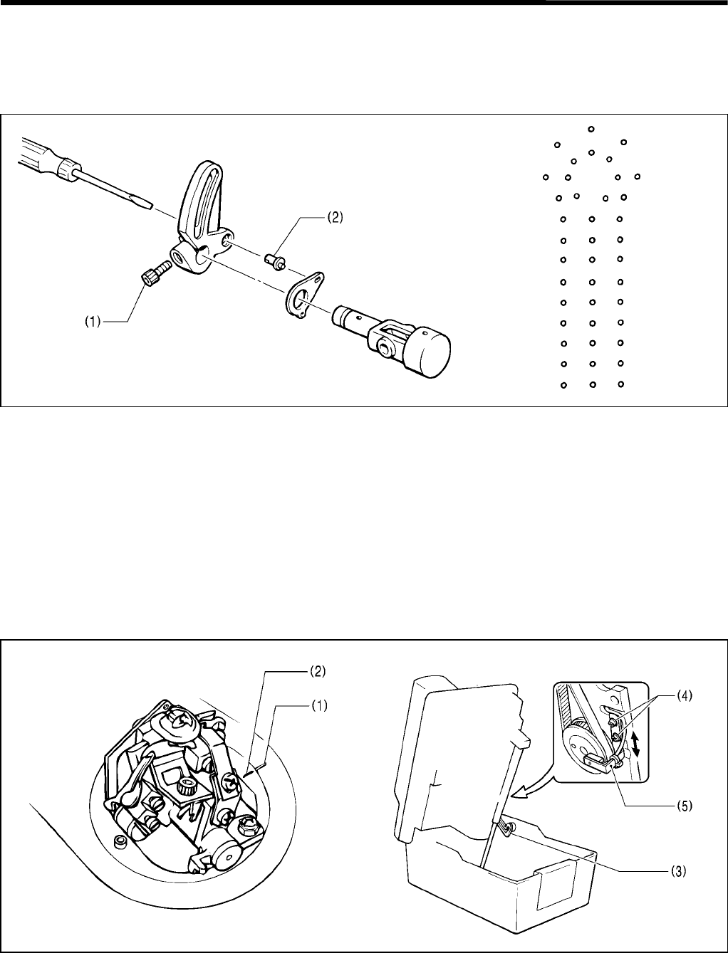
4. ADJUSTMENT
RH-981A
53
4-7. Adjusting 0 position (reference line) of the needle
The 0 position (reference line) of the needle is at the inside needle penetration points.
If the needle gage is changed, the 0 position (reference line) of the needle is not changed, only the outer needle
cloth penetrations are changed.
1. Insert a short needle (for adjustment).
2. Press the OFF key on the operation panel to set no cutting.
3. Place a sheet of paper under the work clamp, and turn the pulley to trace where the needle will penetrate for an
eyelet button hole on the paper.
At this time, adjust the height of the short needle so that it can pebetrate the paper with as small holes as
possible.
4. When the inside needle forward cloth penetration points are not identical with that of the returning ones for the
straight portion, remove the face plate, and loosen the bolt (1).
5. Insert a screwdriver into the arm from the left, and turn the zigzag eccentric pin (2) to adjust.
4-8. Adjusting the home position of the looper base
The match mark in the looper base must be aligned with that on the bed.
1. After detecting the home position, make sure that the match mark (1) in the looper base is aligned with the match
mark (2) in the bed.
2. If it is not, turn off the power.
3. Raise the machine head, secure it using the head support lever (3), loosen the two screws (4), and move the R-
sensor setting plate (5) in the direction of the arrow.
4. Return the machine head to its original position. Repeat above steps from 1.
* The home position of the looper base can be adjusted in increments of 0.45°
3781Q 3782Q
3783Q 3788Q
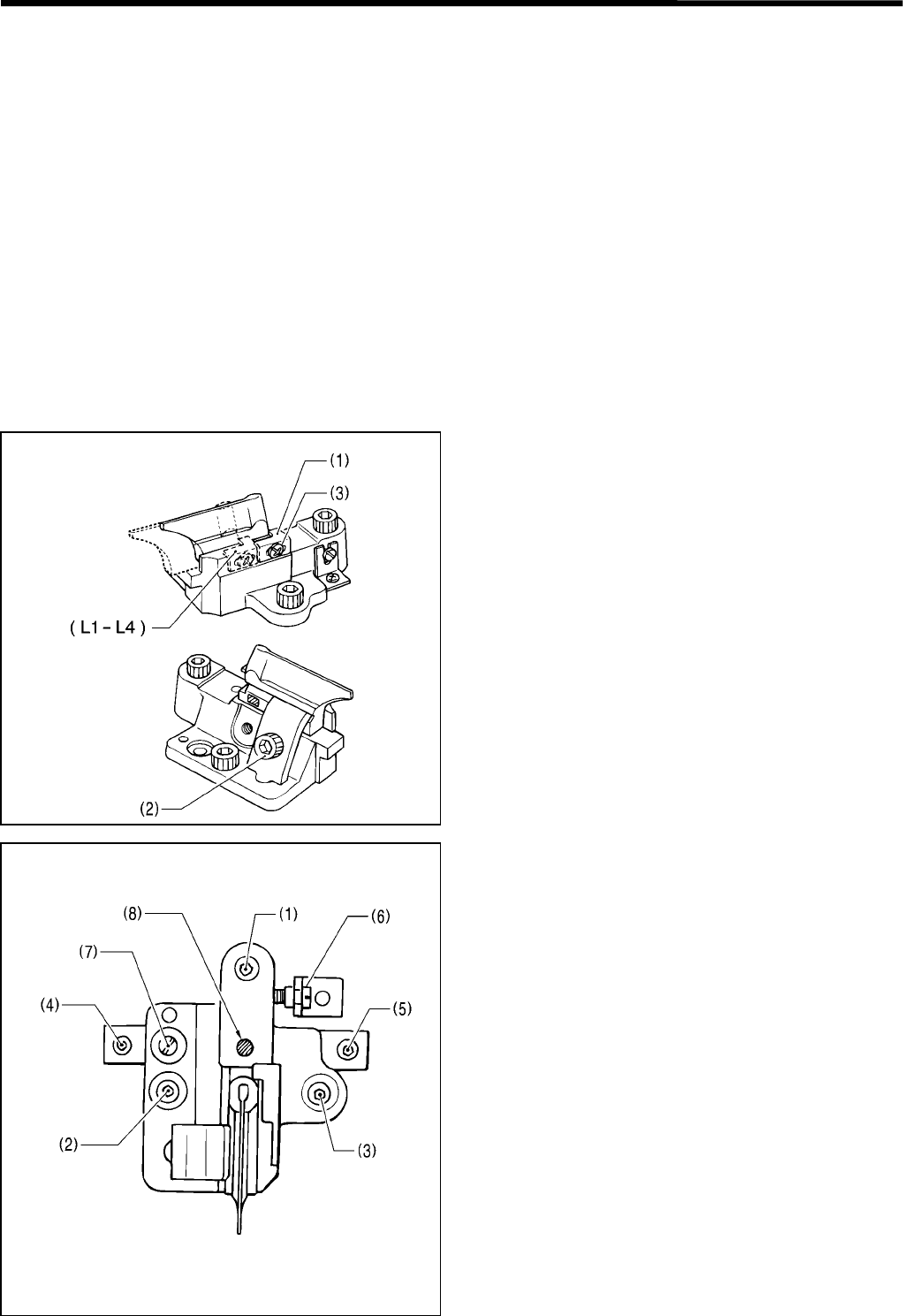
4. ADJUSTMENT
RH-981A 54
4-9. Fine adjustment of knife position
Before this adjustment, make sure that adjustment in “4-7. Adjusting 0 position (reference line) of the needle” has
been completed.
The knife position should be adjusted so that it can correctly cut the eyelet button hole which is formed by the portion
where the needle will penetrate at the inside position and round the eyelet.
The back and forth and sideways movement, and inclination of the knife position can be independently adjusted.
1. Use a short needle (for adjustment).
2. Set the air pressure of the regulator under the table to 0.2 – 0.3 MPa.
* This is to protect the hammer from being damaged by the knife after the knife position is adjusted.
3. Press the AFTER key on the operation panel to set cutting after sewing.
4. Place a sheet of paper under the work clamp, and turn the pulley to trace where the needle will penetrate for an
eyelet button hole on the paper.
5. Make sure that the portion where the needle penetrates for the eyelet button hole uniformly overlaps the knife
cutting positions.
* For easier checking, change the value for cutting space by the parameter settings.
6. If it is not, turn off the power, and adjust the position of the knife.
[Back and forth movement adjustment]
Loosen the bolt (2), and adjust the position of the knife
by following the block stopper plate (1) as a guide.
After adjustment, loosen the screw (3), and press the
block stopper plate (1) against the knife.
[Sideways movement adjustment]
1. Loosen the bolts (1), (2), and (3), of the knife bracket.
2. Loosen the bolts (4) and (5) of the knife bracket
guide.
3. Turn the adjusting screw (6). Fine adjustment for
sideways movement of the knife can be performed
without removing the knife bracket and the knife
bracket guide.
[Inclination adjustment]
1. Loosen the bolts (1), (2), and (3), of the knife bracket.
2. Loosen the bolt (7), which secures the knife bracket
and the knife bracket guide.
3. Turn the adjusting screw (6). Inclination of the knife
can be adjusted by rotating the knife bracket and the
knife bracket guide, regarding the pivot (8) as the
center.
3790Q
3789Q
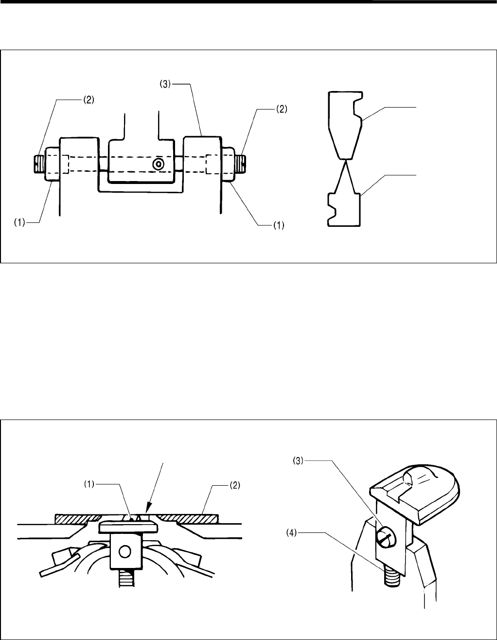
4. ADJUSTMENT
RH-981A
55
4-10. Adjusting the sideways movement of the cutter lever
The cutter lever should be positioned so that the knife can make contact with the center of the hammer.
1. Loosen the two nuts (1).
2. Turn the two support screws (2) to adjust the sideways position of the cutter lever (3).
3. Tighten the two nuts (1).
Note: Adjust the two support screws (2) so that the cutter lever (3) has no end play, and it can operate easily. Too
much end play may damage the knife.
4-11. Adjusting the height of the throat plate
To prevent material from being pressed down by the needle which penetrates the material, the top surface of the
throat plate (1) should be flush with the top surface of the needle plate (2).
Loosen the screw (3), turn the set screw (4), and adjust the height of the throat plate (1).
Note: The set screw (4) is adjusted to maintain the height of the throat plate when it is removed and re-installed.
Hammer
Knife
3791Q 3792Q
3794Q
Align
3793Q
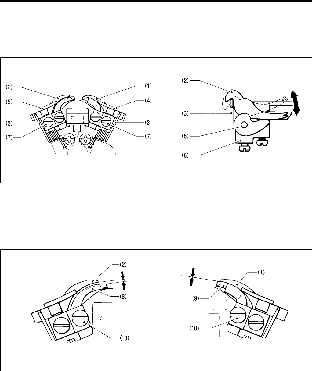
4. ADJUSTMENT
RH-981A 56
4-12. Adjusting the height of the spreader and looper
Spreader height
The clearance between the left spreader (forked spreader) and the eye looper must be set to match the thickness of
the lower thread. The clearance between the right spreader and the right looper should be as small as possible while
still letting the parts slide.
1. The right spreader (1) and left spreader (2) move by means of springs (3). Adjust so that the spreaders move
smoothly between the right spreader stopper (4), the left spreader stopper (5) and the LS-holder bracket (6), with
no looseness.
2. If adjustment is necessary, loosen the screw (7) and then move the right spreader stopper (4) or left spreader
stopper (5) up or down.
Looper height
1. Set the clearance between the eye looper (8) and the left spreader (2) to the same distance as the thickness of
the lower (looper) thread.
2. The clearance between the right looper (9) and the right spreader (1) should be as small as possible.
3. If adjustment is necessary, loosen the screw (10) and then move the eye looper (8) and right looper (9) up or
down.
3072Q
3071Q
3073Q 3074Q
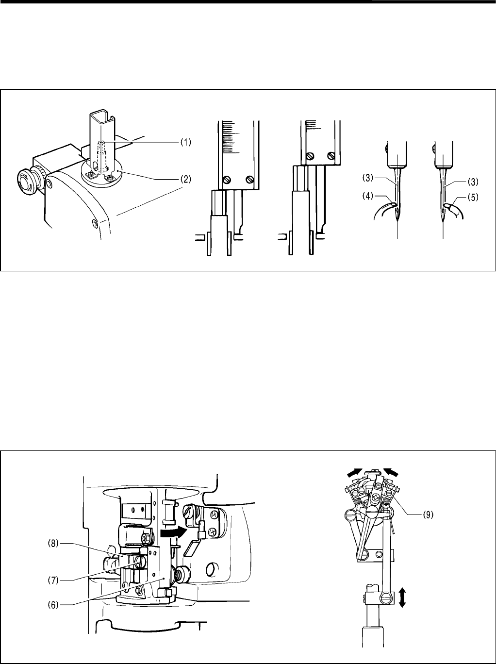
4. ADJUSTMENT
RH-981A
57
4-13. Adjusting the needle and looper timing
The distance by which the needle bar rises from its lowest position to the position where the tip of the eye looper and
the center of the needle are aligned should be the same as the distance from its lowest position to the position where
the tip of the right looper and the center of the needle are aligned.
Before adjusting the looper timing, first adjust the stitch width (needle racking width). (The standard width is 3 mm.)
1. Move the needle bar to its lowest position.
2. Use calipers to measure the distance between the end of the needle bar (1) and the top of the holder base (2)
when the needle bar is at its lowest position.
3. Turn the upper shaft pulley until the tip of the eye looper (4) and the center of the needle (3) are aligned when the
needle (3) is at the inside sewing position, and then use the calipers to take the same measurement as taken in
step 2. Find the difference between the measurements taken in this step and in step 2.
4. Follow the same procedure as in step 3. above to find the difference between the two measurements when the
needle (3) is at the outside sewing position.
* When the needle (3) is at the inside sewing position, the tip of the eye looper (4) should be aligned with the center
of the needle (3), and when the needle (3) is at the outside sewing position, the tip of the right looper (5) should be
aligned with the center of the needle (3).
* The distance from the end of the needle bar (1) and the top of the holder base (2) should be the same when the
needle (3) is at both the inside sewing position and the outside sewing position.
5. If adjustment is necessary, turn the looper base (6) in the direction indicated by the arrow in the illustration, loosen
the screw (7), and then move the looper link clamp (8) up or down to tilt the LS-holder bracket (9) to the left or
right (in the direction of the arrow).
3077Q
3075
Q
3076
Q
Lowest position
of needle bar When center of needle and
looper tip are aligned
0952
Q
3841Q
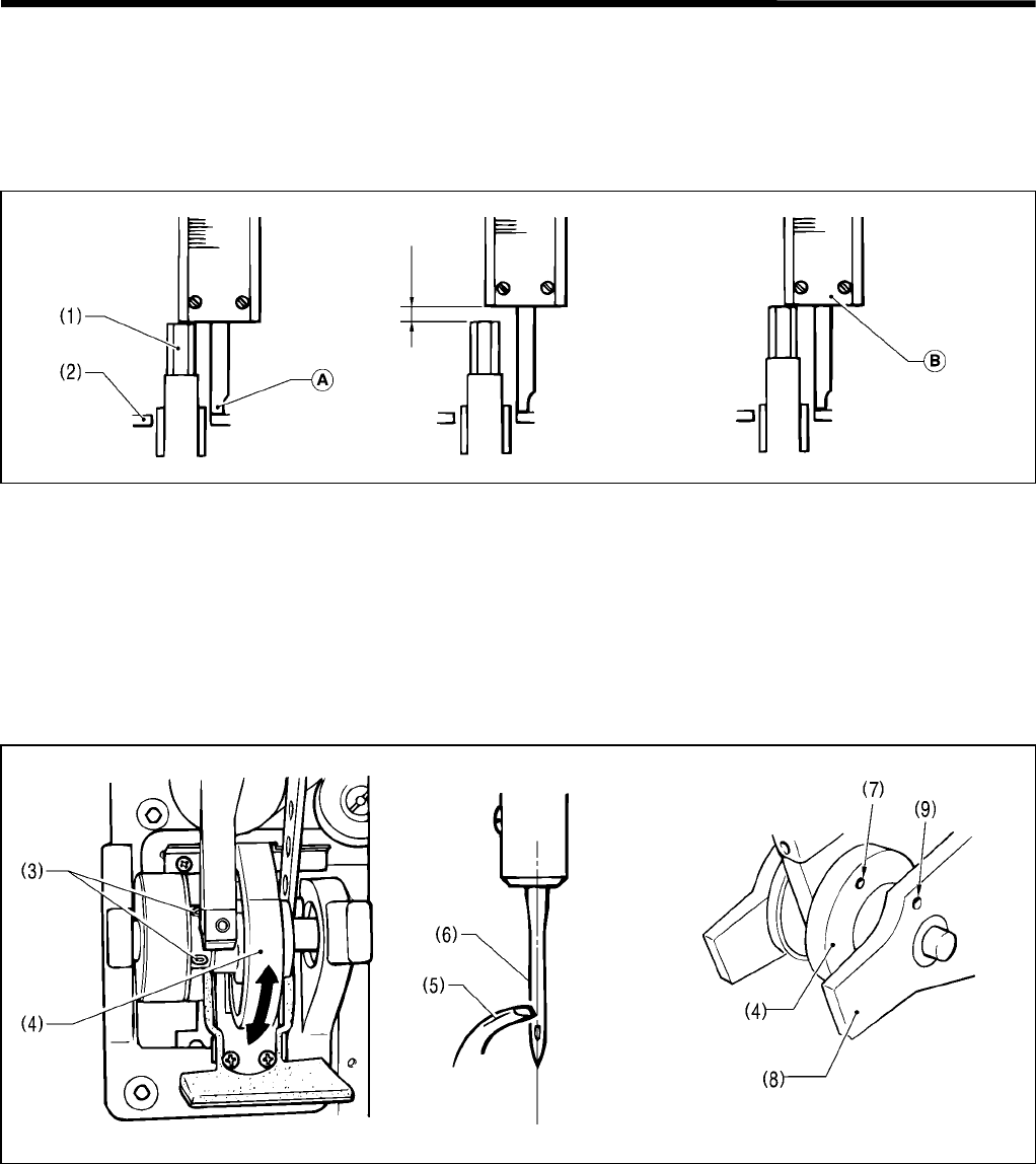
4. ADJUSTMENT
RH-981A 58
4-14. Adjusting the loop stroke
The loop stroke is the distance the needle bar rises from its lowest position to the position where the tips of the eye
looper and right looper are aligned with the center of the needle. The standard loop stroke is 2.7 mm. (The loop
stroke may need changing depending on the material and thread being used.)
* Carry out the adjustment in "4-13. Adjusting the needle and looper timing" before making this adjustment.
1. In the same way as in "4-13. Adjusting the needle and looper timing", move the needle bar to its lowest position
with the needle at the inside sewing position, and then use calipers to measure the distance between the end of
the needle bar (1) and the top of the holder base (2).
2. Add 2.7 mm to the value obtained in step 1. above.
3. Touch the end of the calipers (A) against the top of holder base (2), and then turn the upper shaft pulley until the
end of the needle bar (1) touches the edge of the calipers (B). Check that the tip of the eye looper is aligned with
the center of the needle at this time.
4. In the same way, check that the tip of the right looper is aligned with the center of the needle when the needle is at
the outside sewing position.
5. If the tips of the loopers are not aligned with the center of the needle, carry out the adjustment below.
• Raise the machine head.
• Loosen the two screws (3) of the lower shaft timing pulley, hold the upper shaft pulley so that it doesn't move,
and then turn the lower shaft cam (4) in the direction indicated by the arrow until the tip of the eye looper (5) is
aligned with the center of the needle (6). Once they are aligned, tighten the two screws (3).
• After adjusting, check that the screws have been adequately tightened.
• Once this adjustment has been carried out, repeat the procedure given in "4-13. Adjusting the needle and
looper timing".
* Basically, the machine is assembled so that the hole (7) of the lower shaft cam (4) is aligned with the hole (9) of
the lower shaft base (8) when the needle bar is at its lowest position and at the inside sewing position.
3079Q
3081Q
3080Q 3795Q
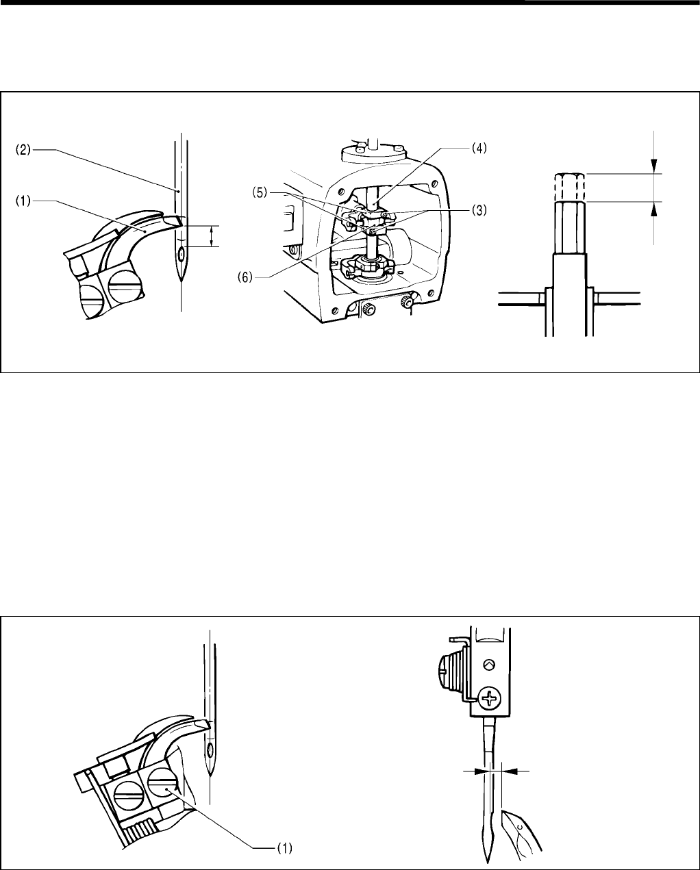
4. ADJUSTMENT
RH-981A
59
4-15. Adjusting the height of the needle bar
The standard height for the needle bar is 2.5 mm. (The needle bar height may need changing depending on the
material and thread being used.)
1. Align the tip of the eye looper (1) with the center of the needle (2) when the needle (2) is at the inside sewing
position.
2. Remove the face plate.
3. Loosen the screw (3) of the needle bar clamp (5) and adjust the height of the needle bar (4).
* After aligning the tip of the eye looper (1) with the top edge of the needle hole, lower the needle bar (4) 2.5 mm.
4. Adjust so that there is as little play as possible, and so that the needle bar clamp (5) and the needle bar level feed
link (6) can maintain their oil films. This will help to ensure that the needle bar turns smoothly.
4-16. Adjusting the clearance between the looper and needle
Be sure to carry out this adjustment after changing the size of the needle.
The clearance between the tip of the looper and the needle should be 0.05 - 0.2 mm.
Loosen the looper screw (1) and then adjust the clearance.
* This clearance must be uniform while the looper base is rotating (through 360o ).
If the clearance is not uniform, adjust the turning center for the needle bar. (This adjustment is made at the time of
shipment from the factory.)
* After making the adjustment in step 1. above, carry out the adjustment procedure given in "4-18. Adjusting the
spreader mounting positions".
3082Q 3083Q 0961Q
2.5 mm
3084Q 0963Q
0.05 - 0.2 mm
2.5 mm
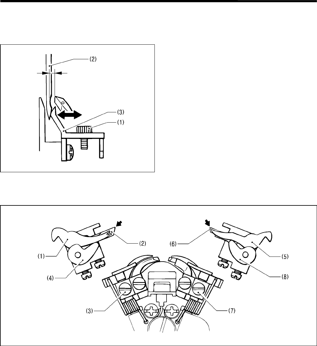
4. ADJUSTMENT
RH-981A 60
4-17. Adjusting the needle guard
Be sure to carry out this adjustment after changing the size of the needle.
The needle must remain stationary with respect to the needle guard until the tip of the looper reaches the needle.
Loosen the screw (1) and then move the needle guard
(3) in the directions indicated by the arrows by an
appropriate amount in accordance with the thickness of
the needle (2).
Note: Adjust so that the looper clasps the upper
thread securely.
4-18. Adjusting the spreader mounting positions
1. Loosen the screw (3) and adjust the position of the left spreader stopper (4) so that the fork of the left spreader (1)
is aligned with the lower thread guide hole of the eye looper (2).
2. Loosen the screw (7) and adjust the position of the right spreader stopper (8) so that the tip of the right spreader
(5) is aligned with the tip of the right looper (6).
Note: Both the left spreader (1) and right spreader (5) should be installed so that they do not project past the tips
of the eye looper (2) and right looper (6) respectively.
3085Q
3086Q
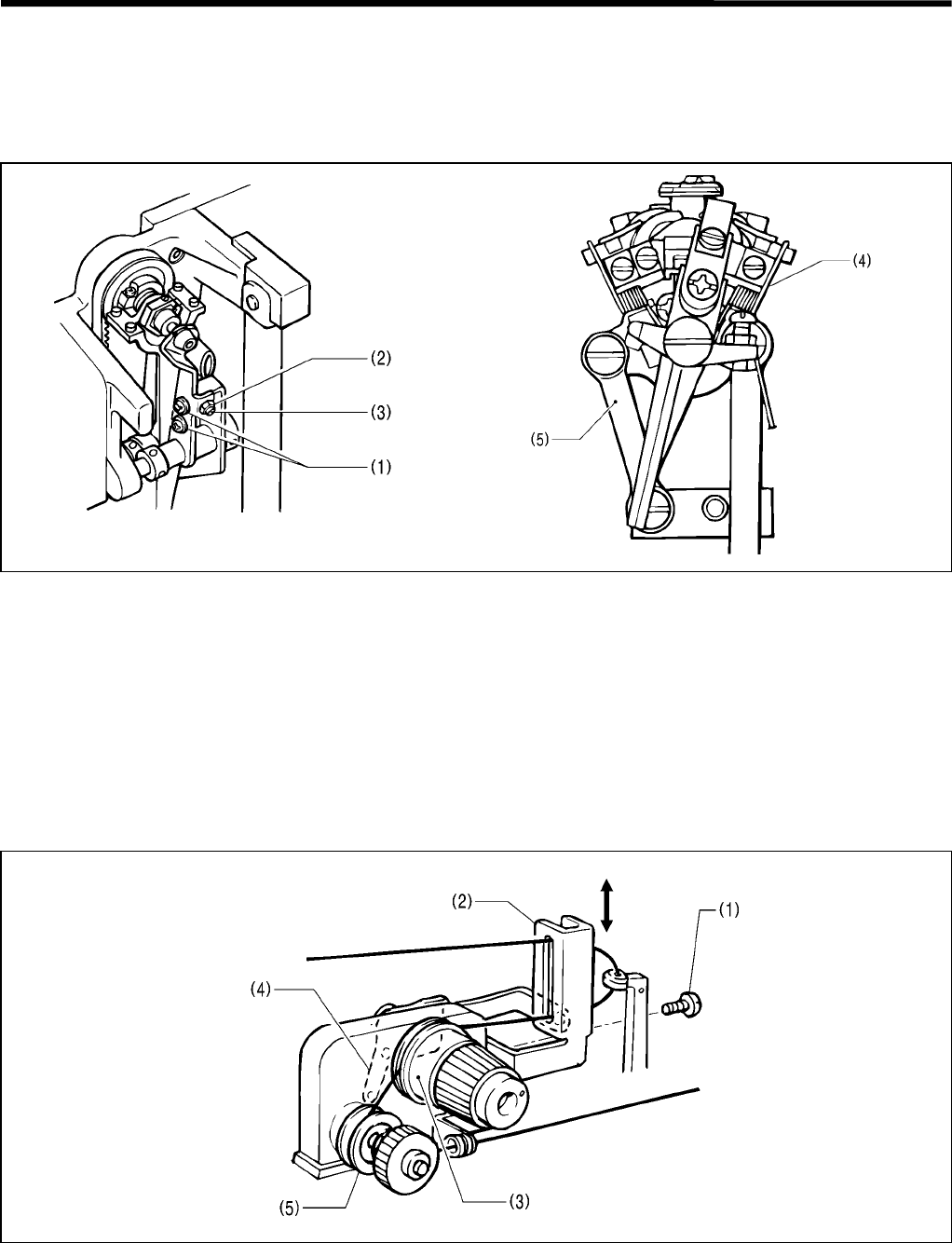
4. ADJUSTMENT
RH-981A
61
4-19. Adjusting the spreader timing
When the needle is at the inside sewing position, the left spreader should touch the left spreader stopper and stop
immediately before the needle bar reaches its lowest position.
When the needle is at the outside sewing position, the right stopper should touch the right spreader stopper and stop
immediately before the needle bar reaches its lowest position.
1. Raise the machine head.
2. Loosen the screw (1) and the nut (2), and then turn the adjusting screw (3) to adjust the spreader timing.
3. After adjusting, tighten the nut (2) and the screw (1).
Note: Make sure that the LS-holder bracket (4) does not touch the spreader cam link (5). If it does, return to “4-13.
Adjusting the needle and looper timing”.
4-20. Adjusting the amount to pull the upper thread and tension release
The amount to pull the upper thread should be sufficiently maintained to form the correct stitches at the start of sewing.
The upper thread take-up lever operates as soon as sewing is completed, and is released when the start switch is
pressed to move the feed bracket with the needle stopped.
Loosen the screw (1), and move the upper thread take-up lever guide (2) up and down to adjust the amount to pull
the upper thread.
• The upper thread tension mechanism has double tension mechanisms. The main tension disc (3) is open after sewing
is completed, and closed when the start switch is pressed to move the feed bracket with the needle stopped.
• The upper thread tension plate (4) and the upper thread take-up lever are interlocked.
• The sub tension disc (5) is always kept closed to give the upper thread tension. The tension will change the
thread end length at the start of sewing.
3087Q 3796Q
Becomes greater
Becomes
less
3797Q
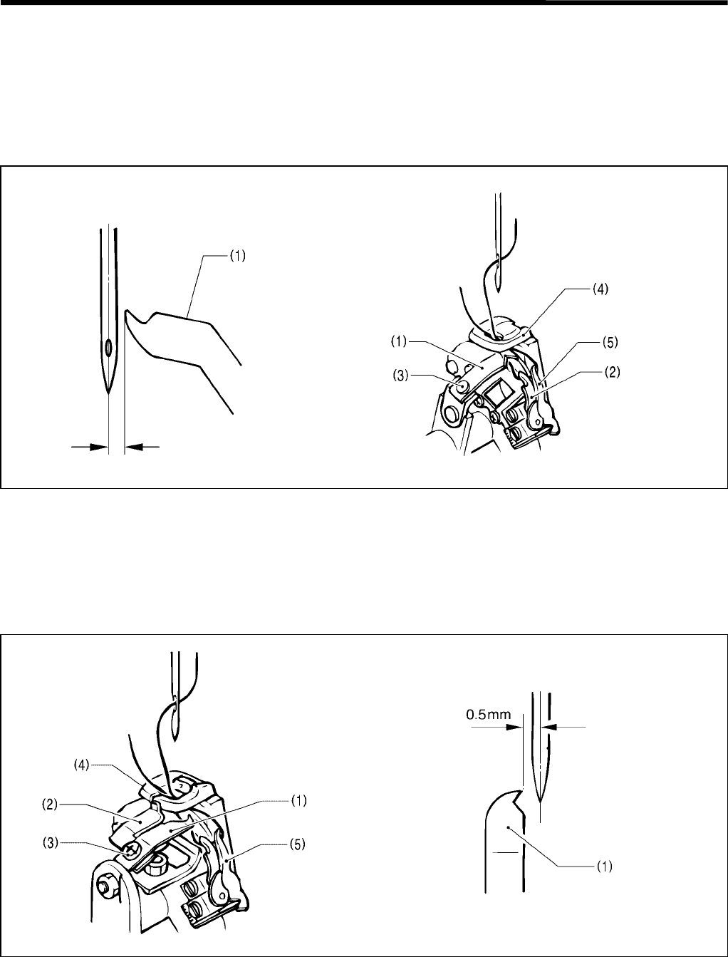
4. ADJUSTMENT
RH-981A 62
4-21. Adjusting upper thread trimming
Upper thread trimming will be performed on the correct time after sewing is completed.
4-21-1.Adjusting the upper movable knife mounting position
[-00, -01]
The upper movable knife (1) must cut the upper loop which is caught by looper R (2), in one place (front). If the
upper loop is cut at 2 places (front and rear), the thread end length from the needle will be shorter, causing skipped
stitches at the start of sewing.
1. Loosen the screw (3), and adjust the clearance between the needle and the point of the upper movable knife (1),
to appox. 0.5 mm.
2. The height of the upper movable knife (1) should be between the bottom of the throat plate (4) and spreader R
(5).
[-02, -52]
The mounting position of upper movable knife (1) is determined by the position of the lower thread presser (2).
1. Loosen the screw (3), and position upper movable knife (1) between the projection of the throat plate (4) and
spreader R (5).
2. Adjust the clearance between the needle and the point of upper movable knife (1) to 0.5 – 1.0 mm.
* If adjustment can not be performed, reconfirm “4-11. Adjusting the height of the throat plate” and “4-23.
Adjusting the position of the lower thread presser”.
Approx. 0.5 mm 3799Q
3798Q
3800Q 3801Q
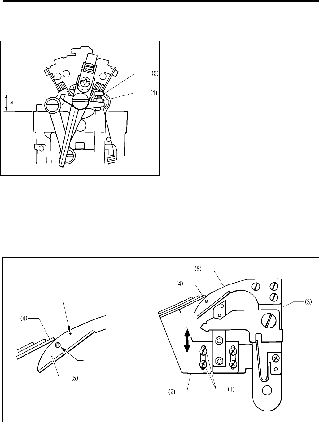
4. ADJUSTMENT
RH-981A
63
4-21-2. Adjusting the position of the thread trimmer lever bracket
When the needle is swinging to the right with the maximum stitch width, the needle should be able to pass the upper
movable knife sufficiently.
Loosen the nut (1), and turn the screw (2) to adjust the
position of the thread trimmer lever bracket.
At this time, dimension a to the shoulder of the thread
trimmer lever bracket should be 10 mm.
Note: Turn the looper base, and make sure that the
thread trimmer lever bracket can smoothly go in
under the thread trimmer lever hammer. The
height of the thread trimmer lever hammer is
adjusted to 11 mm.
4-22. Adjusting the lower thread trimmer (-01 specification)
[Adjusting the thread trimmer which can cut the lower thread and gimp, leaving them longer]
The thread trimmer is operated by means of an air cylinder when the feed bracket is returned to the home position.
4-22-1. Adjusting the knife pressure
Adjust the knife pressure so that the thread can be cut neatly.
Note: Do not subject the knife to excessive pressure. It may cause the knife to wear quickly or damage it.
Loosen the two screws (1), and move the fixed knife setting bracket (2) along the slot which the screws (1) are in, in
the direction of the arrow.
* The standard adjustment is done as shown in the above enlarged view, which indicates the first point to make contact
with the point of the fixed knife (4) and the pin of the movable knife (5) when the thread trimmer arm (3) operates.
3802Q
3804Q
3803Q
Match mark
Align the pin with the point
of the fixed knife (4).
Decrease
pressure.
Increase
pressure.
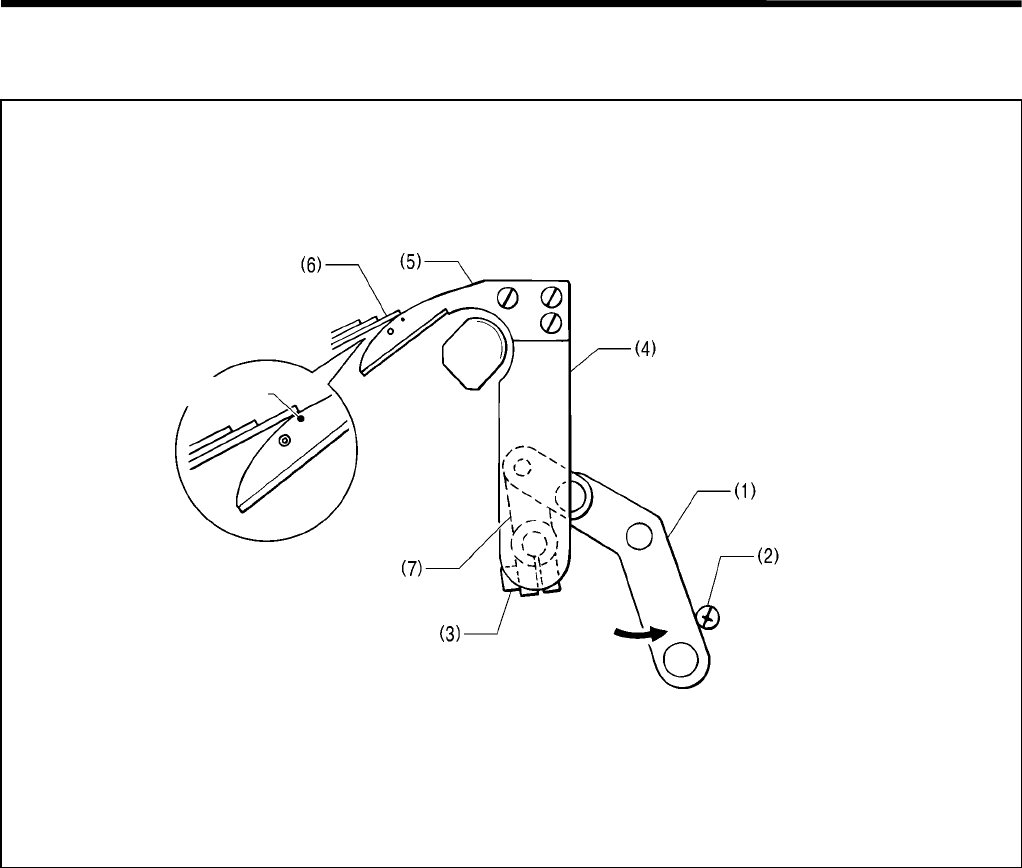
4. ADJUSTMENT
RH-981A 64
4-22-2.Adjusting the position of the thread trimmer arm
The rocking stroke of the thread trimmer arm is fixed to the drive cylinders.
1. Turn the thread trimmer link lever (1) in the direction of the arrow until it touches the stopper screw (2).
2. Loosen the bolt (3), adjust the position of the thread trimmer arm (4), and determine the engagement between the
movable knife (5) and the fixed knife (6). The above figure shows standard adjustment.
Note: When tightening the bolt (3), make sure that the thread trimmer lever arm (7) and the thread trimmer arm
(4) can move smoothly without any end play.
Too little engagement may cause the lower thread not to be hooked, leading to thread cast-off at the start
of sewing.
3805Q
Align the tip of the fixed knife
with the match mark.
Match mark
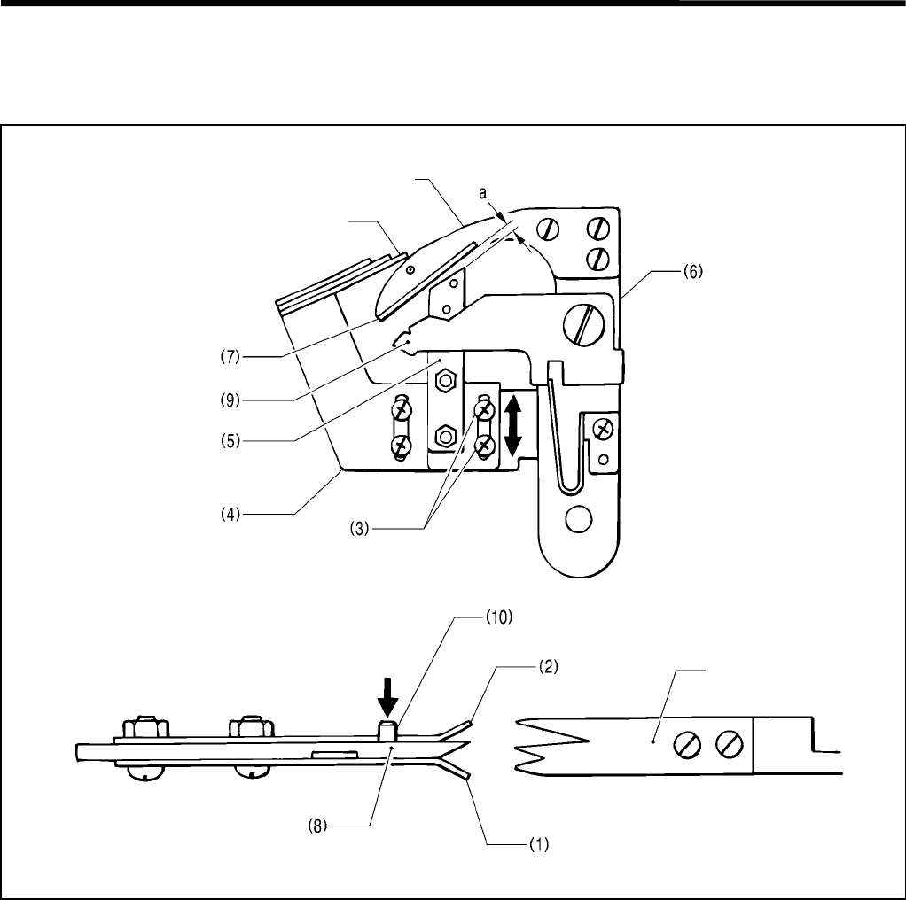
4. ADJUSTMENT
RH-981A
65
4-22-3.Adjusting the thread clamp assembly and thread clamp opener
The lower thread should go under thread clamp D (1); the gimp should go under thread clamp U (2). Install the
thread clamp assembly correctly, and make sure that the thread clamp opener operates correctly.
Loosen the two screws (3), and move the thread clamp assembly (5) along the fixed knife setting bracket (4) in the
direction of the arrow. Decrease clearance a to as narrow as possible so that the thread clamp assembly (5) and the
thread handler (7) do not make contact with each other when the thread trimmer arm (6) rotates.
Note : If clearance a is too great, the lower thread may not be hooked correctly, leading to thread cast-off at the
start of sewing.
If the thread clamp assembly (5) is installed on an angle, thread clamp D (1) may not open because it makes
contact with the throat plate, and fail to hook the lower thread, leading to thread cast-off at the start of
sewing.
The lower thread must pass over the projection of thread clamp M (8), and be securely held by thread clamp D (1).
1. Make sure that thread clamp D (1) is opened at least 0.3 mm when the thread nipper opener (9) presses the
opener pin (10) down.
2. Make sure that thread clamp D (1) is closed just before the thread is trimmed.
3. When the thread trimmer arm (6) returns to its original position after thread trimming, the thread nipper opener (9)
should travel around the opener pin (10). Make sure that thread clamp D (1) should not be open.
Note: When the start switch is pressed and the feed bracket moves to the sewing start point, the lower thread
should be securely hooked by thread clamp D (1).
On the contrary, the gimp should be just released from thread clamp U (2) to prevent double cutting it.
3807Q
3806Q
Movable knife
Fixed knife
Movable knife
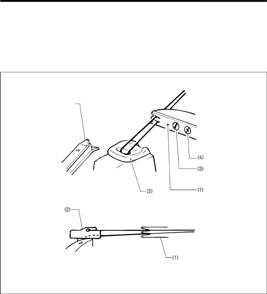
4. ADJUSTMENT
RH-981A 66
4-22-4.Adjusting the thread handler
• The thread handler (1) separates the lower thread and the gimp, and guides them to their respective threading
routes. The lower thread is guided into thread handler D; the gimp is guided into thread handler U.
• When the thread trimmer arm operates, the throat plate (2) turns 45 o.
Then, the gimp moves onto the projection on the throat plate (2), and this creates the height difference between
the lower thread and the gimp. A triangle is formed by the lower thread and the gimp at the last stitch, into which
the thread handler (1) moves to separate the lower thread and the gimp.
1. Set the stitch pitch to 2.0 mm by the parameter settings to decrease the total number of stitches.
2. Press the start switch in the MANUAL mode, and turn the pulley manually until the last stitch.
3. When the pulley is stopped with its match mark aligned with that in the arm after a series of operations is
completed, press the start switch again and again to check each thread trimming operation.
4. Loosen the screws (3) and (4). Adjust the thread handler (1) by turning it while pivoting on the screw (3).
Note: When changing the height of the throat plate (2), be sure to adjust the thread handler (1) because the
triangle formed by the lower thread and the gimp will change.
3808Q
Thread clamp
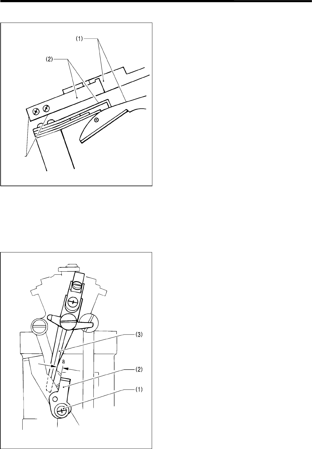
4. ADJUSTMENT
RH-981A
67
4-22-5.Adjusting the thread guide plate
When the movable knife (1) moves, the lower thread
and the gimp should be guided to the notches in the
movable knife (1). Adjust the position of the thread
guide plate (2) so that the end of the movable knife (1)
aligns with the end of the thread guide plate (2).
4-22-6.Adjusting the amount to pull the lower thread required for thread trimming
When the thread handler catches the lower thread to guide it to the fixed knife, the lower thread should be pulled
sufficiently to prevent the thread snapping and deviation from stitching path.
To cut the lower thread when the feed bracket is at the home position, the thread trimmer lever bracket will continue
to operate just before the looper turns 45o, and the lower thread will be pulled.
Loosen the screw (1), turn the tension release plate (2)
to adjust clearance a between the tension release plate
(2) and thread trimmer lever bracket (3).
Note: If the lower thread has snapped, reconfirm “6-1-1.
Adjusting the solenoid valve speed controllers”.
3809Q
Should
align
3810Q
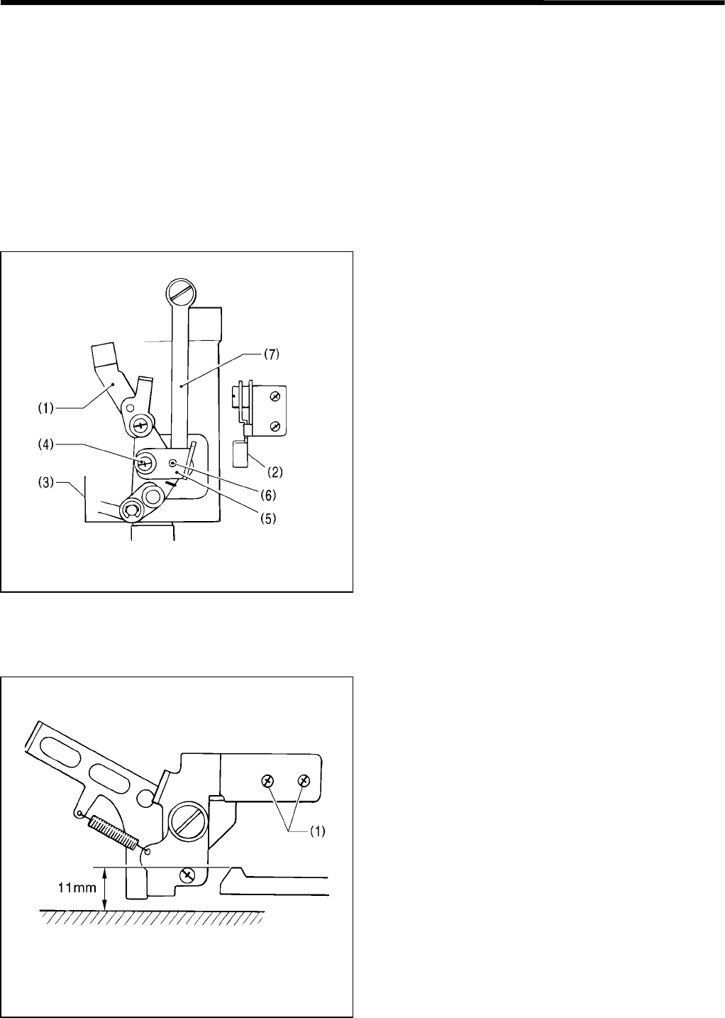
4. ADJUSTMENT
RH-981A 68
4-22-7.Adjusting the amount to pull the lower thread for safety stitching
To secure the first stitch, while looper L is catching the first upper loop, the lower thread should be taut between
looper L and the throat plate, and not be pulled off thread clamp D.
1. After automatic sewing is completed, switch to the MANUAL mode, and press the start switch.
2. Turn the pulley manually to check the condition of the lower thread.
To prevent the lower thread from being pulled off thread clamp D while the feed bracket is moving to the sewing start
position, the pressure of thread clamp D should be sufficiently strong enough, and the tension release lever (1)
should be oscillated by the tension release claw (2) to pull the lower thread appropriately while the looper base
returns to the home position after thread trimming is completed.
When the stitch length is greatly changed, it is necessary to adjust the amount of lower thread to be pulled.
1. Turn off the power.
2. Turn the looper base (3) manually to check the angle
of the tension release lever (1).
3. Loosen the screw (4), turn the tension release claw
(5) regarding the pivot (6) as the center to adjust the
angle of the tension release lever (1).
Note: When the tension release lever (1) oscillates
with its maximum stroke, make sure that it
does not make contact with the looper link
(7).
4-22-8.Adjusting the amount to pull the gimp
The amount of the gimp required for thread trimming is
pulled by the thread trimmer that cuts the lower thread
and the gimp, leaving them longer.
If adjustment is not correct, the gimp sewn in stitches
may be pulled, and stitch formation around the button
eyelet may be distorted.
Loosen the two screws (1), and set the distance from
the bed to the upper end of the roller to 11 mm.
3811Q
3812Q
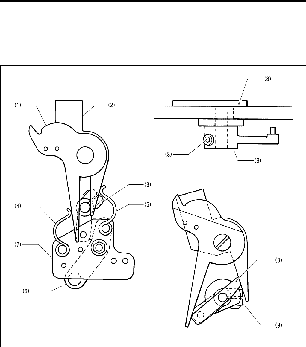
4. ADJUSTMENT
RH-981A
69
4-23. Adjusting the lower thread trimmer (-02, -52 specifications)
[Adjusting the thread trimmer which can cut the lower thread and gimp, leaving them shorter]
The thread trimmer operates by means of an air cylinder when the feed bracket is at the home position.
4-23-1. Adjusting the knife engagement
Movable knives L (1) and R (2) should overlap each other by approx. 1 mm.
1. Loosen the screw (3).
2. With springs L (4) and R (5) attached to movable knives L (1) and R (2), align the end of thread trimmer link lever
J assembly (6) with the match mark on the rear of the link fulcrum plate assembly (7), and tighten the screw (3).
Note: Make sure that the movable knife driving cam (8) and thread trimmer lever arm B (9) rotate smoothly without
any gap.
3. Move thread trimmer link lever J assembly (6) to check engagement between movable knives L (1) and R (2).
4. If the engagement is insufficient, return to step 2 to perform fine adjustment so that the end of thread trimmer link
lever J assembly (6) overlaps with the match mark on the rear of the link fulcrum plate assembly (7).
3815Q3813Q
3814Q
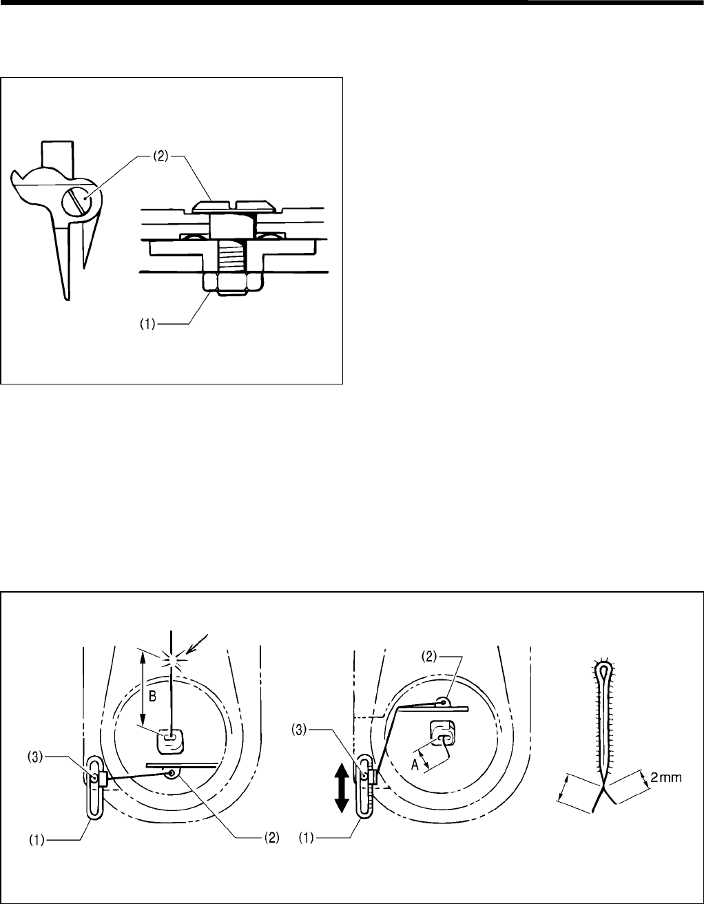
4. ADJUSTMENT
RH-981A 70
4-23-2.Adjusting the knife pressure
Adjust the knife pressure to the lowest where the knife can still cut the material.
1. Loosen the nut (1).
2. Turn the shoulder screw (2) to adjust the knife
pressure.
Note: When the shoulder screw (2) is fully tightened,
the movable knife will not operate. Tighten the
shoulder screw (2) slowly while checking that
the movable knife can operate smoothly.
4-23-3.Adjusting the gimp pull force
• The gimp should be completely sewn in a few stitches at the start of sewing, and the gimp end length from the
stitches should be as small as possible.
• The gimp is pulled by utilizing the difference in distance between gimp thread guide J (1) and gimp thread guide
C-J (2) when the looper base returns to 0 o from 180 o after the gimp is trimmed.
• The gimp is trimmed when the feed bracket is at the home position. When the stitch length is changed,
dimensions B and A will change. It is necessary to adjust the force to pull the gimp.
Also, dimension A differs according to the gimp type and the gimp tension, so it is necessary to adjust the force to
pull the gimp.
Loosen the screw (3), and adjust so that the gimp appears about 2 mm from the first covering stitch at the start of
sewing.
Note: The tip of the gimp is pressed down on the material by a few stitches at the start of sewing, and pulled by the
movement of the feed bracket. If the gimp is excessively taut when the feed bracket is at the sewing start
position, or dimension A is too small, the gimp may come out from under the stitches.
3816Q
3818Q
3817Q
The gimp is trimmed.
Looper base at 0 o
The gimp end length at the end
of sewing is fixed.
Looper base at 180 o
Smaller
Larger
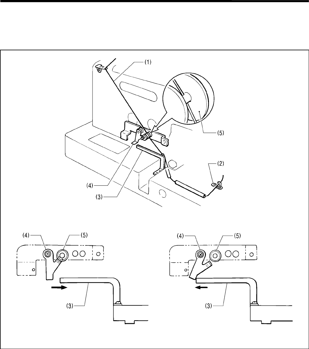
4. ADJUSTMENT
RH-981A
71
4-23-4.Adjusting the gimp tension
When the looper base rotates and the gimp (1) is pulled, the gimp tension at the side of the spool stand should be
stronger than that close to throat plate, regarding gimp thread guide J (2) as the center.
During sewing, on the contrary, the tension should be weak so that the gimp can be sewn under the stitches.
1. During sewing, gimp thread take-up guide J (3) moves toward the front in accordance with the movement of the
feed bracket, and the gimp thread release plate (4) releases the thread tension disc (5).
2. After sewing is completed, the feed bracket moves to the home position to trim the gimp (1), gimp thread take-up
guide J (3) pushes the gimp thread release plate (4), and the thread tension disc (5) is closed.
3821Q3820Q
3819Q
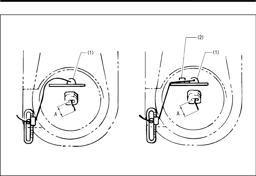
4. ADJUSTMENT
RH-981A 72
4-23-5.Using gimp thread work clamp
When the gimp is stiff, dimension A (gimp length from the throat plate) may vary.
In this case, pass the gimp through gimp thread work clamp (2) attached to gimp guide C-J (1).
Note: When thick and soft gimp is passed through gimp thread work clamp (2), the gimp tension may be too great
during sewing.
3823Q
3822Q
The gimp is slack. Threading route maintained.
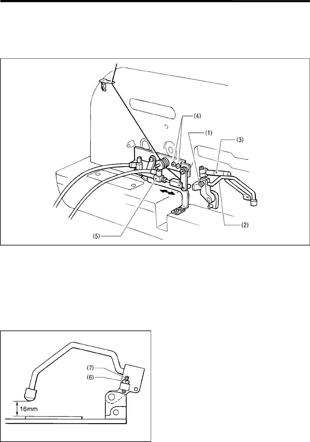
4. ADJUSTMENT
RH-981A
73
4-23-6.Adjusting the auxiliary clamp arm
The auxiliary clamp arm holds the material until the lower thread and the gimp are trimmed after the work clamp
rises.
The auxiliary clamp arm should be adjusted so that it can operate when the feed bracket is at the home position, and
will be stationary on the needle plate without subjecting it to any pressure.
1. Loosen the bolt (1), and position the auxiliary clamp arm (2) on the needle plate so that the auxiliary clamp arm
(2) can hold the material next to work clamp.
Note: Be sure that the auxiliary clamp arm (2) does not make contact with clamp arm L-J (3).
2. Turn on the power to set the home position.
3. Turn off the air, and loosen the two screws (4).
4. With the rod of the auxiliary clamp arm cylinder (5) fully extended, adjust so that the auxiliary clamp arm (2) can
be stationary to the needle plate without subjecting it to any pressure.
Note: If excessive pressure is applied to the auxiliary clamp arm when the feed bracket is at the home position,
the feed bracket may be in an inappropriate position in the Y direction.
The lift height of the auxiliary clamp arm is set to 16 mm.
Loosen the nut (6), and turn the screw (7) to adjust the
height.
3824Q
3825Q
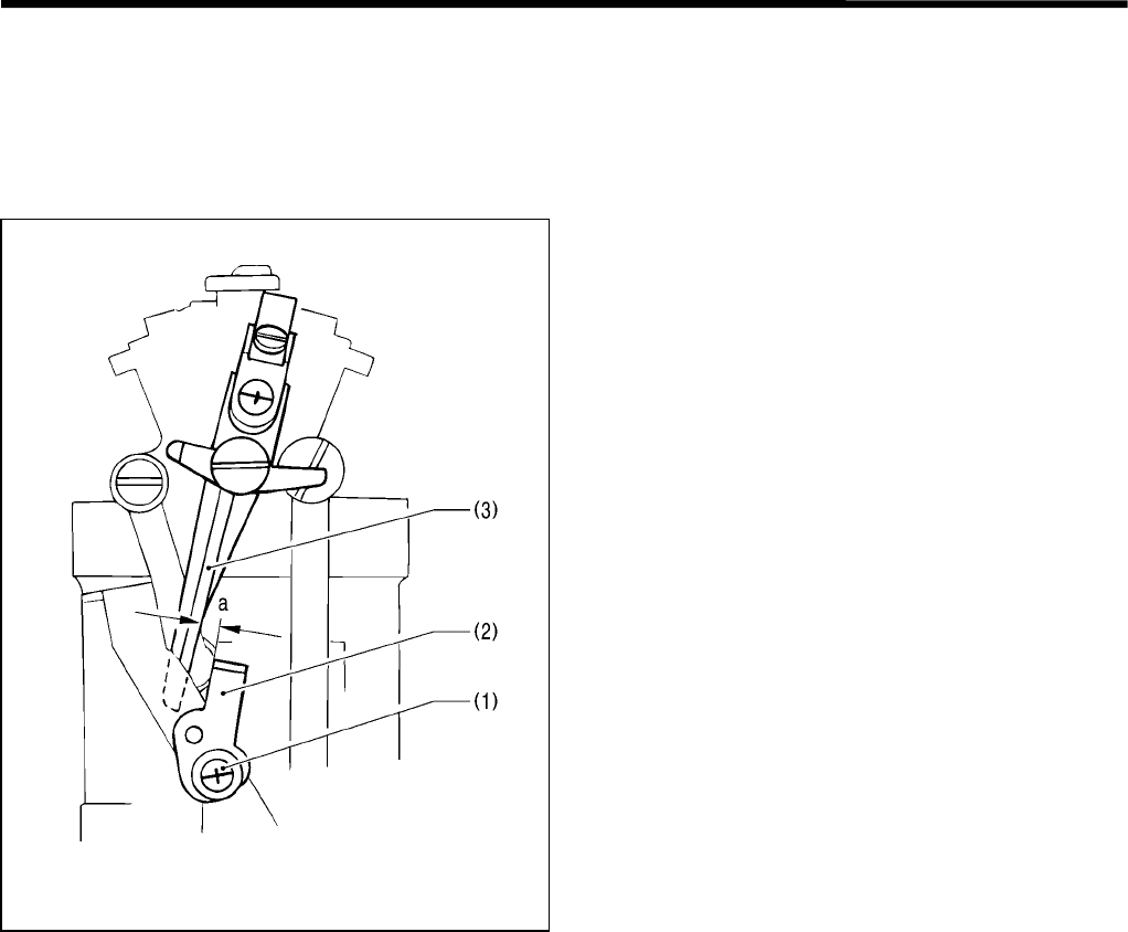
4. ADJUSTMENT
RH-981A 74
4-23-7.Adjusting the length of the lower thread to be pulled for a safe sewing start
To secure the first stitch, while looper L is holding the first upper loop, the lower thread should be taut between
looper L and the throat plate, and not be pulled off the lower thread presser.
Thread trimmer lever bracket B is operating just before the lower thread is trimmed when the feed bracket is at the
home position, and that causes the lower thread to be pulled.
1. After automatic sewing is completed, switch to the
MANUAL mode, and press the start switch.
2. Turn the pulley manually to check the condition of the
lower thread.
3. If adjustment is necessary, loosen the screw (1), and
turn the tension release plate (2) to adjust distance a
between the tension release plate (2) and thread
trimmer lever bracket B (3).
3810Q
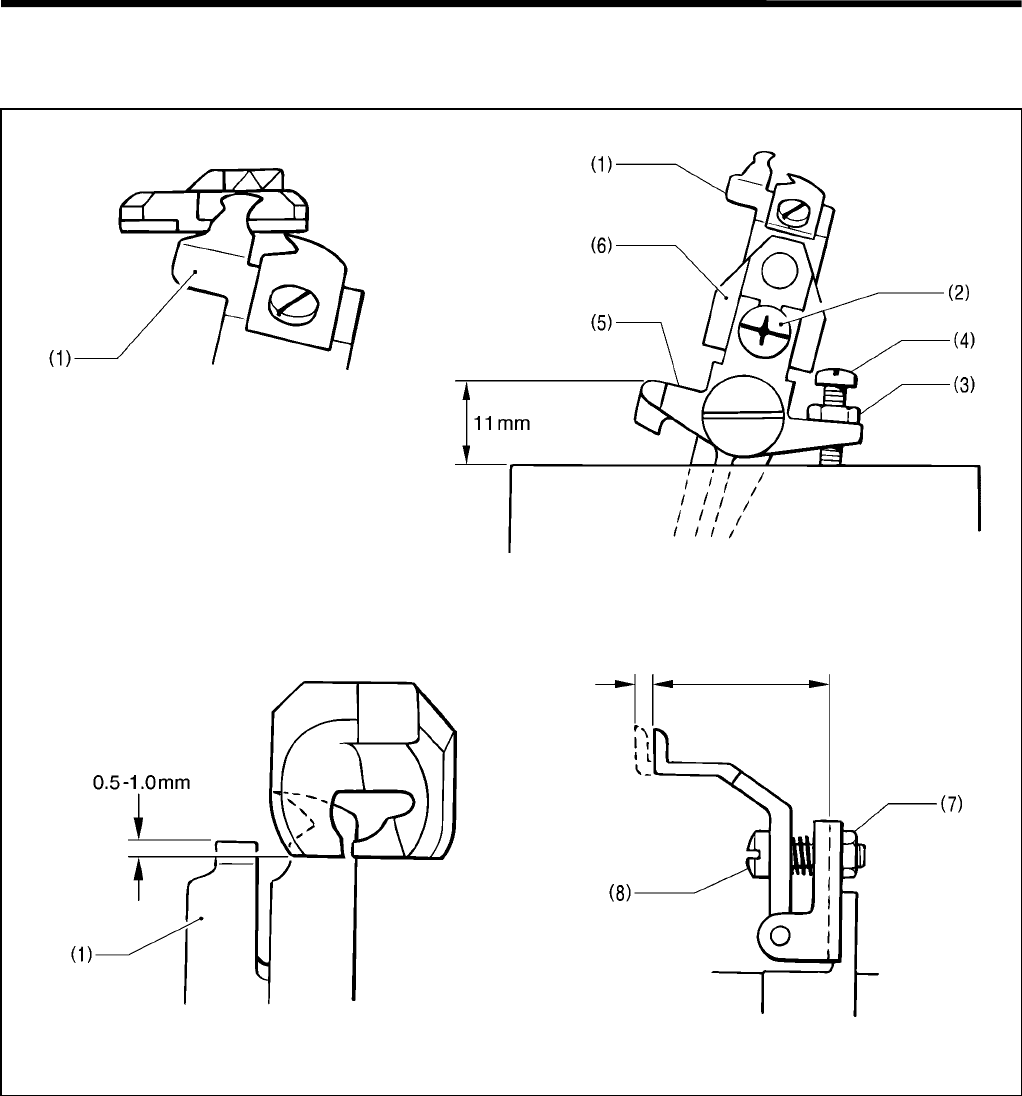
4. ADJUSTMENT
RH-981A
75
4-24.
Adjusting the position of the lower thread presser (-02, -52 specifications)
The lower thread presser (1) should be adjusted so that it can securely clamp the lower thread.
1. Loosen the screw (2), and move the lower thread presser (1) up and down so that its top surface is flush with the
groove in the throat plate.
2. Make sure that the lower thread presser (1) does not fill the front groove of the throat plate.
If it does, loosen the nut (3), and adjust the screw (4).
Note: Set the height from the stopper portion of thread trimmer lever bracket B (5) to the top of the looper base,
to 11 mm at maximum.
3. Make sure that the front of the throat plate overlaps with the lower thread presser (1) by 0.5 – 1.0 mm when
thread trimmer lever bracket B (5) operates.
4. If adjustment is necessary, remove the lower thread presser bracket (6), loosen the nut (7), and adjust the screw
(8).
3826Q 3827Q
3828Q 3829Q
Lap amount
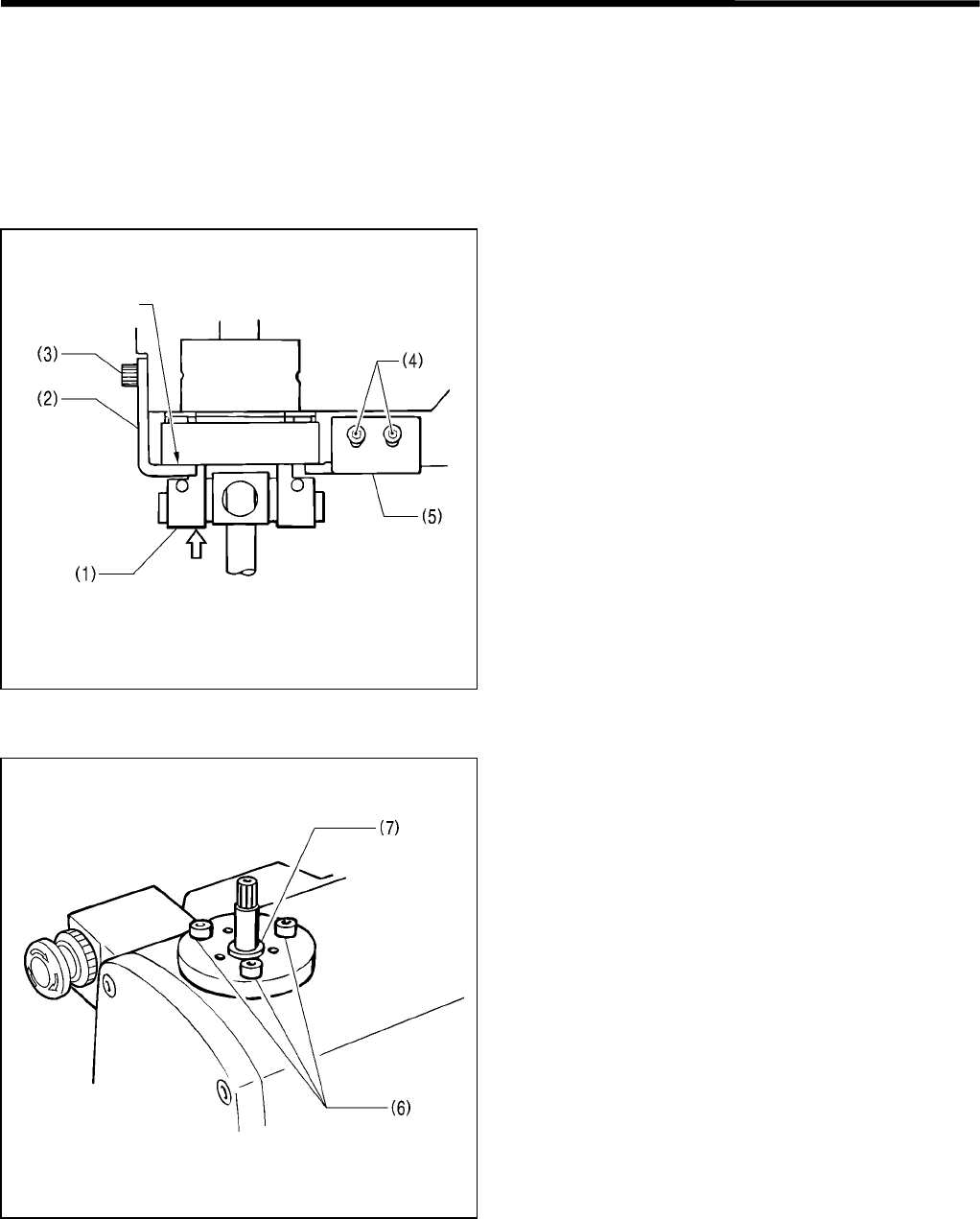
4. ADJUSTMENT
RH-981A 76
4-25. Adjusting the rotating centers of the needle bar and the looper base
The rotating centers of the needle bar and the looper base are adjusted before shipment from the factory.
When disassembling the machine or exchanging parts such as the needle bar gear assembly, the needle bar, and
looper base, adjust the clearance between the needle and the point of the looper so that it does not change through
360 o.
Before adjusting the position of needle bar bush U, be sure to check there is no gap between the needle bar gear (1)
and needle bar gear support A (2).
1. Raise the needle bar gear (1) using your fingers to
check the loseness.
Note: If the looseness is great, the center of
rotation can not be adjusted.
2. Loosen the two bolts (3), and adjust needle bar gear
support A (2) so that the needle bar gear assembly
can rotate smoothly without gap.
3. Loosen the two bolts (4), and adjust needle bar gear
support B (5) in the same manner as above.
Note: When needle bar gear support A (2) or
needle bar gear support B (5) is raised
excessively, the looper base may be in an
inappropriate position.
When the looper base is at 360 o where the needle bar can move lightly up and down, adjust the position of needle
bar bush U (7).
Loosen the three bolts (6) a little, and tap on the needle
bar to adjust the position of needle bar bush U (7).
* Adjust the back and forth movement of needle bar
bush U (7) so that the clearance between the needle
and the point of the looper is not changed when the
looper base is at 0 o and 180 o.
Adjust the sideways movement of needle bar bush U
(7) so that the clearance between the needle and the
point of the looper is not changed when the looper
base is at 90 o and 270 o.
Note: If the needle penetration movement is
adjusted to one point, the clearance between
the needle and the point of the looper will not
be fixed.
No looseness
Press manually.
3830Q
3831Q
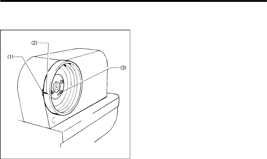
4. ADJUSTMENT
RH-981A
77
4-26. Adjusting the needle bar stop position
The needle bar should stop when it rises from the lowest point at the outside sewing position.
Loosen the screw (3), and align the notch (1) of belt
cover F with the timing mark (2) on the pulley.
Note: When the stop position is changed, the
operation range of spreader R will change.
Reconfirm the mounting position of the upper
movable knife.
3832Q
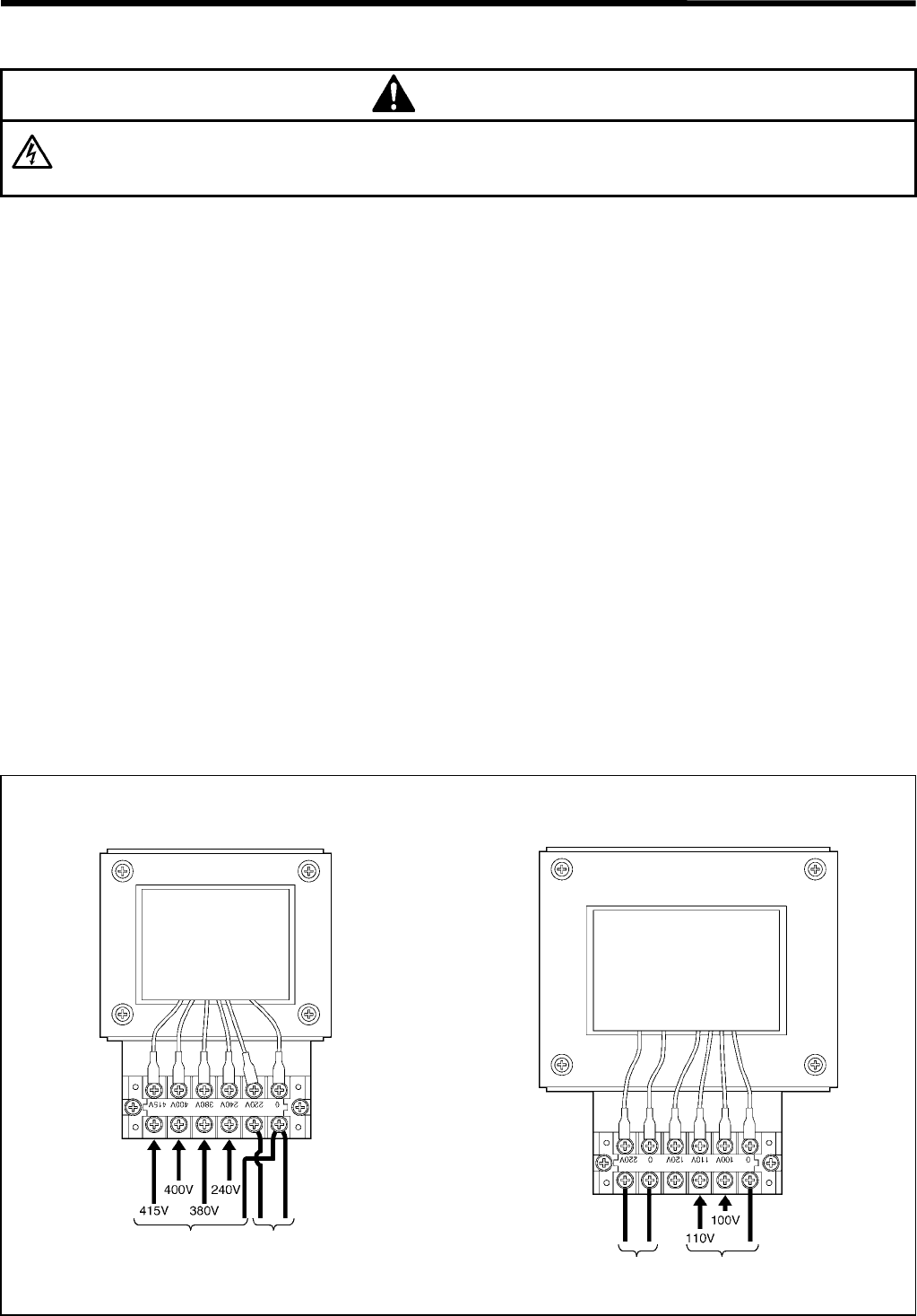
5. POWER SUPPLY EQUIPMENT
RH-981A
78
5. POWER SUPPLY EQUIPMENT
DANGER
Wait at least 5 minutes after turning off the power switch and disconnecting the power cord from the wall
outlet before opening the face plate of the control box. Touching areas where high voltages are present
can result in severe injury.
Be sure to turn off the power and disconnect the plug before replacing and adjusting the parts associated with the
power supply equipment.
5-1. Components inside the control box
The following are brief explanations of components inside the control box. See control circuit block diagram at the
end of this manual for the details of the connections.
Control circuit board
The control circuit board is fixed to the rear panel of the control box.
This PCB serves to control machine operation.
Power supply circuit board
The power supply circuit board is fixed at the bottom of the control box.
Four fuses are mounted on this PCB. (Refer to “5-2. Fuse explanation”.)
PMD PCB for θ-axis shaft
The PMD PCB for θ-axis shaft is fixed to the board on the top of the control box.
This is used to run the θ-axis pulse motor.
DC fan motor (large)
Cools the heat sink on the PCB.
DC fan motor (small)
Discharges air in the control box. Clean the inlet filter monthly.
Conversion transformer (depending on power supply voltage specification)
Adjust the power voltage so that it is that required for the PCB.
* There are two types of transformers: a high voltage transformer is equipped with 240V, 380V, 400V, and 415V
specifications; a low voltage transformer is equipped with 100V and 110V specifications.
Transformer connections
1145S
Input side
1144S
Power supply
circuit board side
<415V, 400V, 380V, 240V> <100V,110V>
Power supply
circuit board side
Input side
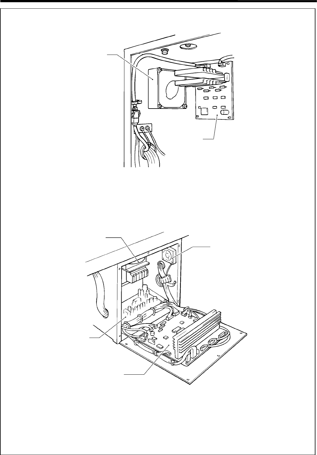
5. POWER SUPPLY EQUIPMENT
RH-981A
79
3518Q
DC fan motor (large)
PMD PCB for
θ-axis shaft
Conversion
transformer DC fan motor (small)
Power supply
circuit board
3519Q
<Rear of the control box>
Control circuit board
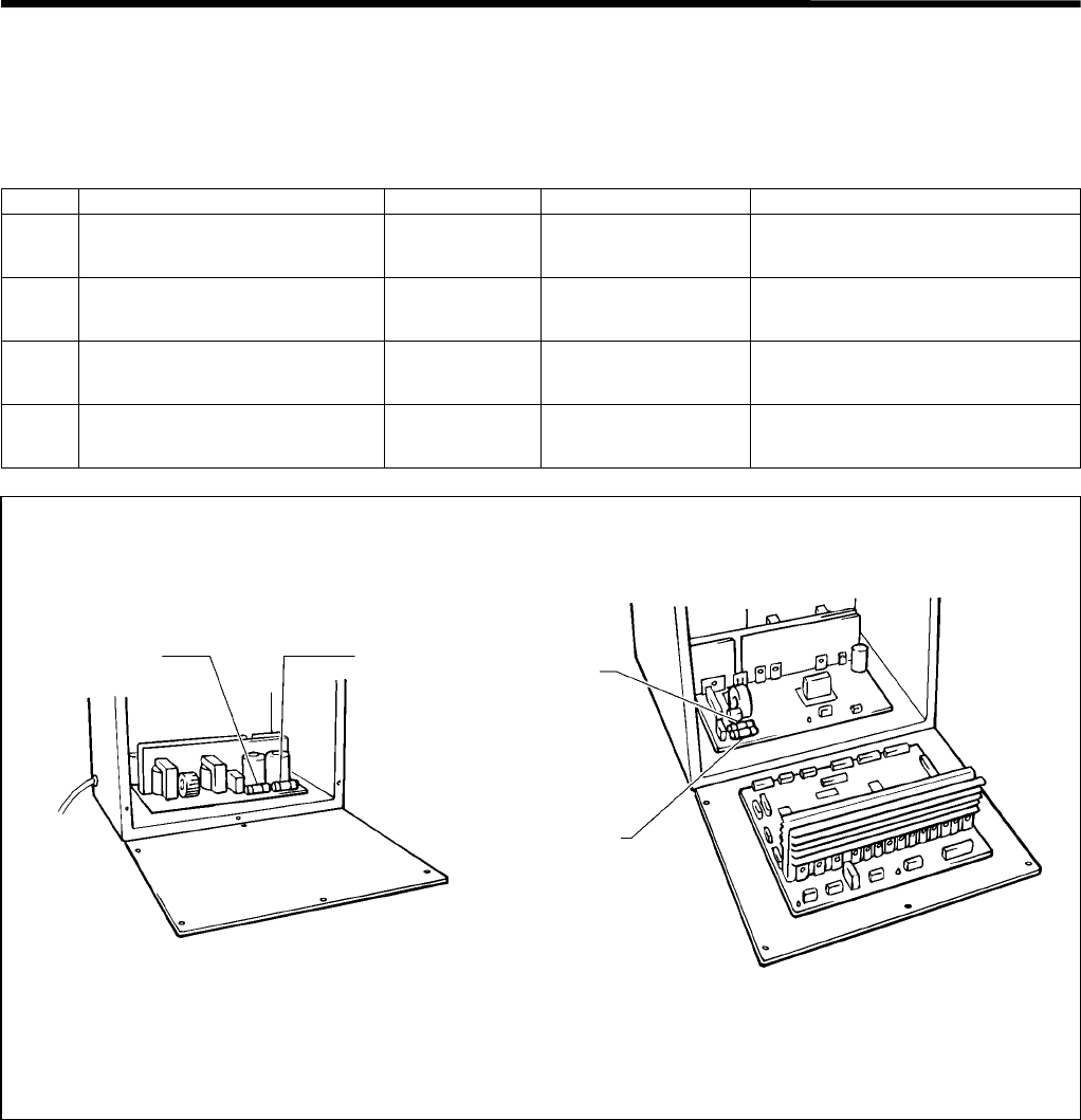
5. POWER SUPPLY EQUIPMENT
RH-981A
80
5-2. Fuse explanation
Before replacing a fuse, be sure to read “5-2-1. Before replacing a fuse”.
If a component on a PCB is damaged, a fuse may blow again immediately even when it has been replaced.
When replacing a fuse, be sure to use the specified ones listed below.
No. Part name Part code Manufacturer When a fuse has blown
1G fuse (5AFB)
(quick melting type, 5A-250V) S08030-000 Toyo Fuse Company
TOYO5A
The feed mechanism does not
operate.
2G fuse (5AFB)
(quick melting type, 5A-250V) S08030-000 Toyo Fuse Company
TOYO5A
The machine motor does not
turn.
3Fuse 6A
(glass tube fuse, 6A-250V) 153242-000 Fuji Tanshi Company
FGB0
The power indicator is not lit, and
nothing operates.
4Fuse 6A
(glass tube fuse, 6A-250V) 153242-000 Fuji Tanshi Company
FGB0
The power indicator is not lit, and
nothing operates.
3521Q3520Q
Front Rear
Fuse
No.2 Fuse
No.3
Fuse
No.4
Fuse
No.1
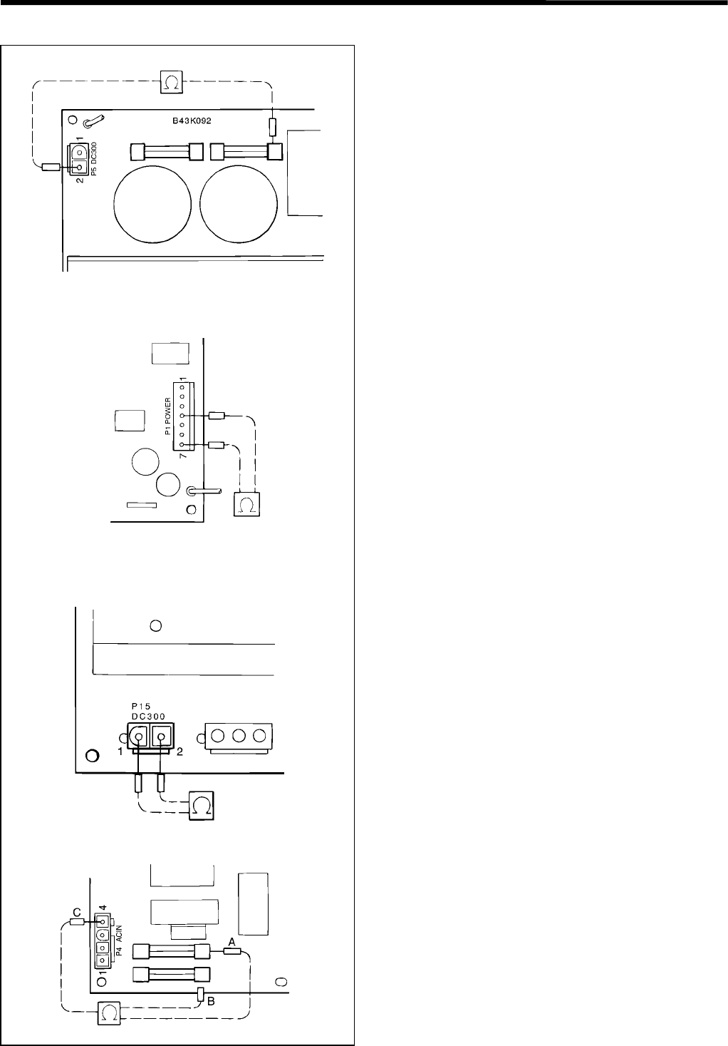
5. POWER SUPPLY EQUIPMENT
RH-981A
81
5-2-1. Before replacing a fuse
If fuse No.1 is blown
1. Separate connectors P5 (DC300) on the power
supply circuit board, and measure the resistance with
the polarities as shown in the figure.
If the resistance is 0 ohms (it means a short-circuit),
replace the power supply circuit board.
2. Separate connectors P1 (POWER) on the power
supply circuit board, and measure the resistance
between pins 4 and 7 on the board with the polarities
as shown in the figure.
If the resistance is 0 ohms (it means a short-circuit),
replace the power supply circuit board.
If fuse No.2 is blown
Separate connectors P15 (DC300) on the control circuit
board, and measure the resistance between pins 1 and
2 on the board with the polarities as shown in the figure.
If the resistance is 0 ohms (it means a short-circuit),
replace the power supply circuit board.
If fuse No.3 or 4 is blown
Separate connectors P1 (ACIN) on the power supply
circuit board, and measure the resistance of the three
places between A and B, A and C, and B and C on the
board with the polarities as shown in the figure.
If the resistance is 0 ohms (it means a short-circuit), or
the resistance between A and C or B and C is not infinity,
replace the power supply circuit board.
3522Q
BLACK
BLACK
RED
3523Q
3524Q
RED BLACK
3525Q
RED
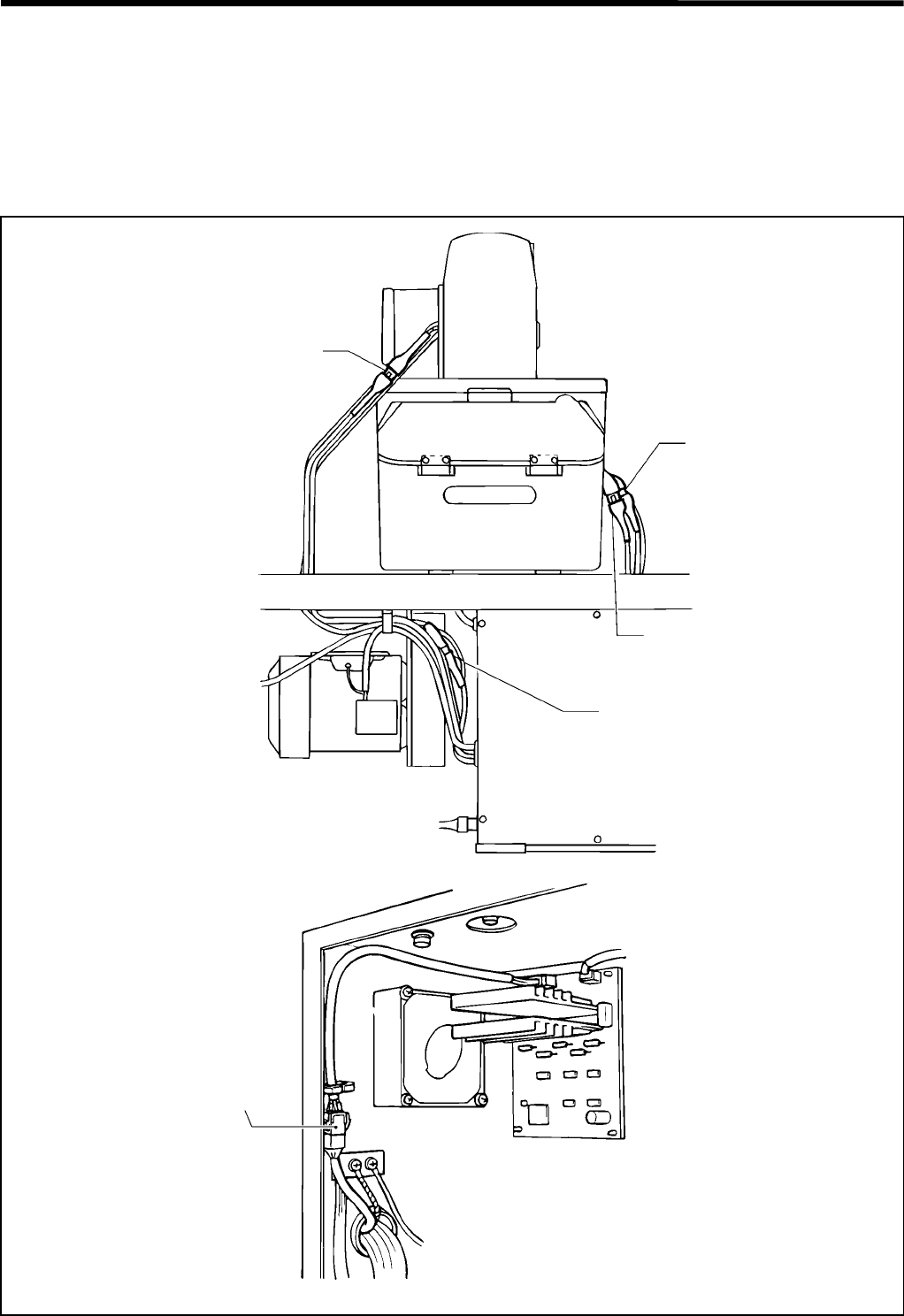
5. POWER SUPPLY EQUIPMENT
RH-981A
82
5-3. Connectors
Most of the machine trouble is due to connector problems including improper connection or insufficient contact.
Therefore, be sure to check if each connector is correctly inserted and that there is no contact failure between pins
and wires before starting troubleshooting procedures.
5-3-1. Connector positions
Head harness relay
3526Q
For θ–axis pulse motor (red)
For θ–axis home position sensor
3527Q
For X–axis pulse motor
(white)
For Y–axis pulse motor
(blue)
For θ–axis pulse motor (red)
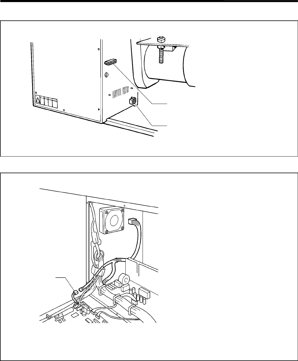
5. POWER SUPPLY EQUIPMENT
RH-981A
83
Outside of the control box
Inside of the control box
3528Q
For specification harness
For hand switch (for foot switch)
Note: This type-harness B is only for -12
specifications. If this harness is no
t
connected, you will not be able to run
programs for -12 specification sewing
machines.
3529Q
Type harness B
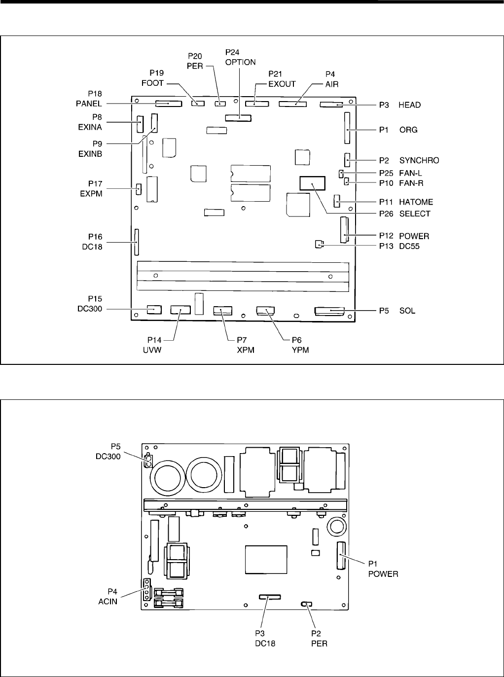
5. POWER SUPPLY EQUIPMENT
RH-981A
84
Control circuit board
Power supply circuit board
3530Q
3531Q
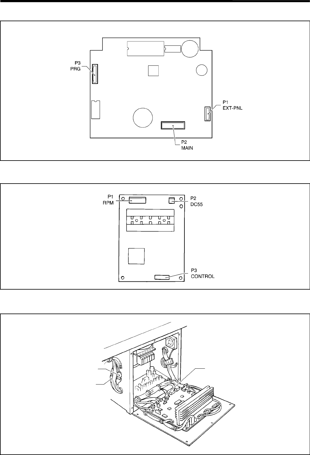
5. POWER SUPPLY EQUIPMENT
RH-981A
85
Panel circuit board
PMD PCB for θ-axis shaft
Indexer mechanism (optional)
3532Q
3533Q
3534Q
Indexer sensor harness
is inserted into the relay
connector for θ–axis
home position sensor.
Relays the valve harness
of the indexer.
The harness which relays the
valve of the indexer is inserted
into connector P21 (EXOUT)
of the control circuit board.

5. POWER SUPPLY EQUIPMENT
RH-981A
86
5-3-2. Signal names for connectors and probable symptoms due to poor contact
1. Relay connectors
For X-axis pulse motor (MOLEX 5557-06R, 5559-06P)
Pin no. Signal name Probable symptoms due to poor contact
1 X-axis PM driving current (XA)
2 X-axis PM driving current (XB)
3 X-axis PM driving current (XC)
4 X-axis PM driving current (XD)
5 X-axis PM driving current (XE)
6-
• Left and right movement of feed bracket is not
correct.
• X-axis home position can not be found.
• Error code E80 appears.
For Y-axis pulse motor (MOLEX 5557-06R, [blue], 5559-06P [blue])
Pin no. Signal name Probable symptoms due to poor contact
1 Y-axis PM driving current (YA)
2 Y-axis PM driving current (YB)
3 Y-axis PM driving current (YC)
4 Y-axis PM driving current (YD)
5 Y-axis PM driving current (YE)
6-
• Back and forth movement of feed bracket is not
correct.
• Y-axis home position can not be found.
• Error code E81 appears.
For θ-axis pulse motor (MOLEX 5557-06R [red], 5559-06P [red])
Pin no. Signal name Probable symptoms due to poor contact
1θ-axis PM driving current (RA)
2θ-axis PM driving current (RB)
3θ-axis PM driving current (RC)
4θ-axis PM driving current (RD)
5θ-axis PM driving current (RE)
6-
• Needle bar motion is not correct.
•θ-axis home position can not be found.
• Error code E82 appears.

5. POWER SUPPLY EQUIPMENT
RH-981A
87
For θ-axis home position sensor (AMP 172163-1, 172171-1)
Pin no. Signal name Probable symptoms due to poor contact
1+5V (for θ-axis home position sensor)
2+5V
3+24V
4+24V (for right cylinder driving sensor)
(when indexer is attached)
5-
6θ-axis home position sensor signal
7
Feed plate home position sensor signal
(when indexer is attached) /
Button hole cloth sensor (when special
lapel cutting device is attached)
8Reserved
9
Right driving sensor (when indexer is
attached) /
Button hole position sensor (when special
lapel cutting device is attached)
10
Left driving sensor (when indexer is
attached) /
Hammer home position sensor (when
special lapel cutting device is attached)
11 0V (for θ-axis home position sensor)
12 0V (for feed plate home position sensor)
(when indexer is attached)
13 0V
14 0V (for right driving sensor)
(when indexer is attached)
15 0V (for left driving sensor)
(when indexer is attached)
• θ-axis home position can not be found.
• Error code E52 or E82 appears.
• Indexer does not work properly.
• Special lapel cutting device does not work properly.
• One of error codes E06, E07, E36, E37, E38, E66,
E67, E68, E200, E201, E202 and E203 appears.
For specification harness (MOLEX 5557-16R, 5559-16P)
Pin no. Signal name Probable symptoms due to poor contact
1 TYPE 1 (COM)
2 TYPE 2 (COM)
3 TYPE 3 (COM)
4 TYPE 4 (COM)
5 TYPE 5 (COM)
6 TYPE 6 (COM)
7 TYPE 7 (COM)
8 TYPE 8 (COM)
9 TYPE 1
10 TYPE 2
11 TYPE 3
12 TYPE 4
13 TYPE 5
14 TYPE 6
15 TYPE 7
16 TYPE 8
• Error code E09 appears.

5. POWER SUPPLY EQUIPMENT
RH-981A
88
For hand switch (foot switch) (AMP 172161-1, 172169-1)
Pin no. Signal name Probable symptoms due to poor contact
1Work clamp switch signal (common
side)
2 Work clamp switch signal
3 Reserved (common side)
4Reserved
5Ground
6-
7 Start switch signal (common side)
8 Start switch signal
9-
• Work clamp does not work when work clamp switch is
pressed.
• Machine does not start.
• Home position detection is not possible immediately after
the power is turned on.
For indexer valve (MOLEX 5025-15P1, 5025-15R1) (when indexer is attached) /
For upper thread nipper (MOLEX 5025-15P1, 5025-15R1) (when upper thread nipper is attached) /
For special lapel cutting valve (MOLEX 5025-15P1, 5025-15R1) (when special lapel cutting device is attached)
Pin no. Signal name Probable symptoms due to poor contact
1Reserved
2Upper thread nipper [1] (upper and
lower)
3Upper thread nipper [2] (Open and
close)
4Feed plate fixing valve motion
signal
5
Chuck valve motion signal /
Special lapel cutting valve motion
signal
6+24V
7+24V
8+24V
9 +24V (for feed plate fixing valve)
10 +24V (for chuck valve)
11 Feed plate driving valve signal
12 +24V (for feed plate driving valve)
13 -
14 -
15 -
• Indexer does not work properly.
• Upper thread nipper does not work properly.
• Special lapel cutting device does not work properly.
• One of error codes E07, E37, E38, E66, E67 and E68
appears.
2. Connectors to be attached to control circuit board
P1 [ORG] (JAPAN SOLDERLESS TERMINAL MFG. CO., LTD. XHR-12)
Pin no. Signal name Probable symptoms due to poor contact
1-
2 X-axis home position sensor signal
30V (for X-axis home position
sensor)
4+5V (for X-axis home position
sensor)
5-
6 Y-axis home position sensor signal
70V (for Y-axis home position
sensor)
8+5V (for Y-axis home position
sensor)
9-
10 Pressure sensor signal
11 0V (for pressure sensor)
12 -
• X-axis or Y-axis home position can not be found.
• One of error codes E50, E51, E80 and E81 appears.
• Error codes E05 or E35 appears. (when pressure sensor is
attached)

5. POWER SUPPLY EQUIPMENT
RH-981A
89
P2 [SYNCHRO] (JAPAN SOLDERLESS TERMINAL MFG. CO., LTD. XHR-5)
Pin no. Signal name Probable symptoms due to poor contact
1+5V
2 Encoder timing signal
3 Needle down signal
4 Needle up signal
50V
• Machine motor does not run.
• Sewing machine motor is running unevenly.
• One of error codes E10, E40, E70, E71, E76, E77,
and E91 appears.
P3 [HEAD] (JAPAN SOLDERLESS TERMINAL MFG. CO., LTD. XHR-9)
Pin no. Signal name Probable symptoms due to poor contact
1Emergency stop switch normal close
signal
2 0V (for emergency stop switch)
3 Emergency stop switch normal open signal
4-
5-
6-
• Error code E60 appears and machine stops.
• One of error codes E00, E12, E30, E42, and E72
appears.
7 +5V (for knife ON sensor)
8 Knife ON sensor signal
9 Knife ON sensor cathode
P4 [AIR] (JAPAN SOLDERLESS TERMINAL MFG. CO., LTD. H12P-SHF-AA)
Pin no. Signal name Probable symptoms due to poor contact
1 Upper thread adjuster valve signal
2 Upper thread trimmer valve signal
3 Lower thread trimmer valve signal
4 Knife driving valve signal
5 Cloth opener valve signal
6-
7-
8 Work clamp valve
9-
10 +24V (for work clamp, cloth opener, and
lower thread trimmer)
11 +24V (for upper thread adjuster, upper
thread trimmer, and knife driving)
12 -
• Upper thread adjuster does not work.
• Upper thread can not be trimmed.
• Lower thread can not be trimmed.
• Knife does not work.
• Cloth opener does not work.
• Work clamp does not work.
• One of error codes E12, E15, E42, E45, E72, and
E75 appears.
P5 [SOL] (not connected)
P6 [YPM] (JAPAN SOLDERLESS TERMINAL MFG. CO., LTD. VHR-5N [blue])
Pin no. Signal name Probable symptoms due to poor contact
1 Y-axis PM driving current (YA)
2 Y-axis PM driving current (YB)
3 Y-axis PM driving current (YC)
4 Y-axis PM driving current (YD)
5 Y-axis PM driving current (YE)
• Back and forth motion of feed bracket is not correct.
• Y-axis home position can not be found.
• Error code E81 appears.
P7 [XPM] (JAPAN SOLDERLESS TERMINAL MFG. CO., LTD. VHR-5N)
Pin no. Signal name Probable symptoms due to poor contact
1 X-axis PM driving current (XA)
2 X-axis PM driving current (XB)
3 X-axis PM driving current (XC)
4 X-axis PM driving current (XD)
5 X-axis PM driving current (XE)
• Left and right motion of feed bracket is not correct.
• X-axis home position can not be found.
• Error code E80 appears.

5. POWER SUPPLY EQUIPMENT
RH-981A
90
P8 [EXINA] (JAPAN SOLDERLESS TERMINAL MFG. CO., LTD. PHDR-16VS)
Pin no. Signal name Probable symptoms due to poor contact
1 0V (for head safety switch)
2 Head safety switch signal
3-
4 0V (for lower thread trimming OFF sensor)
5 Lower thread trimming OFF sensor signal
6+24V
(for lower thread trimming OFF sensor)
7 0 V (for TYPE 5)
8 TYPE 5
9-
10 0 V (for TYPE 6)
11 TYPE 6
12 -
13 0 V (for TYPE 7)
14 TYPE 7
15 -
16 -
• One of error codes E02, E09, E15, E32, E45, E62,
and E75 appears.
P9 [EXINB] (JAPAN SOLDERLESS TERMINAL MFG. CO., LTD. PHDR-18VS)
Pin no. Signal name Probable symptoms due to poor contact
10V (for left driving sensor)
(when indexer is attached)
2Left driving sensor signal
(when indexer is attached)
3+24V (for left driving sensor)
(when indexer is attached)
40V (for right driving sensor)
(when indexer is attached)
5Right driving sensor signal
(when indexer is attached)
6+24V (for right driving sensor)
(when indexer is attached)
7-
8-
9-
10 0V (for feed plate home position sensor)
(when indexer is attached)
11 Feed plate home position sensor signal
(when indexer is attached)
12 +24V (for feed plate home position sensor)
(when indexer is attached)
13 0V (for θ-axis home position sensor)
14 θ-axis home position sensor signal
15 -24V
16 +5V
17 +5V
18 +5V (for θ-axis home position sensor)
•θ-axis home position can not be found.
• Error code E52 or E82 appears.
• Indexer does not work properly.
• One of error codes E06, E07, E36, E37, E38, E66,
E67, and E68 appears.

5. POWER SUPPLY EQUIPMENT
RH-981A
91
P10 [FAN-R] (JAPAN SOLDERLESS TERMINAL MFG. CO., LTD. PHR-3)
Pin no. Signal name Probable symptoms due to poor contact
1+24V
2 Fan lock error signal
30V
• Error code E93 appears.
P11 [HATOME] (JAPAN SOLDERLESS TERMINAL MFG. CO., LTD. PHDR-12VS)
Pin no. Signal name Probable symptoms due to poor contact
1-
2-
3-
4-
5θ-axis PM clock signal
6θ-axis PM direction signal
7θ-axis PM save signal
8θ-axis PM excitation signal
9+5V
10 +5V
11 0V
12 0V
• Rotation motion of feed mechanism is not correct.
•θ-axis position can not be found.
• Error code E52 or E82 appears.
P12 [POWER] (JAPAN SOLDERLESS TERMINAL MFG. CO., LTD. VHR-7N)
Pin no. Signal name Probable symptoms due to poor contact
1+5V
2+24V
30V
4+55V
5+55V
60V (P0V)
70V (P0V)
• Power does not come on.
• Feed bracket does not move.
• Machine operation becomes unstable.
• Home position can not be found.
• Error code E80 appears.
P13 [DC55] (JAPAN SOLDERLESS TERMINAL MFG. CO., LTD. VHR-2N)
Pin no. Signal name Probable symptoms due to poor contact
1+55V
20V (P0V)
• Feed bracket does not move.
• Home position can not be found.
• Error code E80 appears.
P14 [UVW] (MOLEX3191-03R1)
Pin no. Signal name Probable symptoms due to poor contact
1 Machine motor U phase
2 Machine motor V phase
3 Machine motor W phase
• Machine motor does not run.
• Rotation of machine motor is not correct.
• Error code E70 or E91 appears.
P15 [DC300] (MOLEX3191-02R1)
Pin no. Signal name Probable symptoms due to poor contact
10V (for machine motor)
2 +300V
• Machine motor does not run.
• Rotation of machine motor is not correct.
• Error code E70 or E91 appears.

5. POWER SUPPLY EQUIPMENT
RH-981A
92
P16 [DC18] (JAPAN SOLDERLESS TERMINAL MFG. CO., LTD. PHR-11)
Pin no. Signal name Probable symptoms due to poor contact
1 +18V (A18V)
20V (A0V)
3-
4 +18V (B18V)
50V (B0V)
6-
7 +18V (C18V)
80V (C0V)
9-
10 +18V (D18V)
11 0V (D0V)
• Machine motor does not run.
• Rotation of machine motor is not correct.
• Error code E70 or E91 appears.
P17 [EXPM] (not attached)
P18 [PANEL] (JAPAN SOLDERLESS TERMINAL MFG. CO., LTD. XHR-10)
Pin no. Signal name Probable symptoms due to poor contact
10V
20V
3 Send (CHO)
4 DTR (CHO)
5Receive (CHO)
6 DSR (CHO)
7+11V
8-11V
9+5V
10 +5V
• No keys on panel are activated.
P19 [FOOT] (JAPAN SOLDERLESS TERMINAL MFG. CO., LTD. PHR-6)
Pin no. Signal name Probable symptoms due to poor contact
1 Start switch signal (common side)
2 Start switch signal
3 Work clamp switch signal (common side)
4 Work clamp switch signal
5 Reserved (common side)
6Reserved
• Work clamp does not move when work clamp switch
is pressed.
• Machine does not start.
• Home position detection is not possible immediately
after the power is turned on.
P20 [PER] (JAPAN SOLDERLESS TERMINAL MFG.CO., LTD PHR-5)
Pin no. Signal name Probable symptoms due to poor contact
1 Relay condition input
2 Primary voltage detect
3 Relay OFF output
4 +55V OFF output
50V
• One of error codes E26, E92, E98, and E99 appears.

5. POWER SUPPLY EQUIPMENT
RH-981A
93
P21 [EXOUT] (JAPAN SOLDERLESS TERMINAL MFG. CO., LTD. H10P-SHF-AA) (when indexer is attached)
Pin no. Signal name Probable symptoms due to poor contact
1 Feed plate driving valve motion signal
2 Chuck valve motion signal
3 Feed plate fixing valve motion signal
4Reserved
5Reserved
6Reserved
7-
8-
9+24V
10 +24V
• Indexer does not work properly.
• One of error codes E07, E37, E38, E66, E67 and E68
appears.
P24 [OPTION] (not attached)
P25 [FAN-L] (JAPAN SOLDERLESS TERMINAL MFG. CO., LTD. PHR-3)
Pin no. Signal name Probable symptoms due to poor contact
1+24V
2 Fan lock error signal
30V
• Error code E94 appears.
P26 [SELECT] (MOLEX 5566-10A)
Pin no. Signal name Probable symptoms due to poor contact
1 TYPE 1
2 TYPE 2
3 TYPE 3
4 TYPE 4
5 TYPE 8
6 0V (for TYPE 1)
7 0V (for TYPE 2)
8 0V (for TYPE 3)
9 0V (for TYPE 4)
10 0V (for TYPE 8)
• Error code E09 appears.

5. POWER SUPPLY EQUIPMENT
RH-981A
94
3. Connectors to be attached to power supply circuit board
P1 [POWER] (JAPAN SOLDERLESS TERMINAL MFG. CO., LTD. VHR-7N)
Pin no. Signal name Probable symptoms due to poor contact
1+5V
2+24V
30V
4+55V
5+55V
6 0V(P0V)
7 0V(P0V)
• Power does not come on.
• Feed bracket does not move.
• Machine operation becomes unstable.
• Home position can not be found.
• Error code E80 appears.
P2 [PER] (JAPAN SOLDERLESS TERMINAL MFG. CO., LTD. PHR-5)
Pin no. Signal name Probable symptoms due to poor contact
1 Relay condition input
2 Primary voltage detect
3 Relay OFF output
4 +55V OFF output
50V
• One of error codes E26, E92, E98, and E99 appears.
P3 [DC18] (JAPAN SOLDERLESS TERMINAL MFG. CO., LTD. PHR-11)
Pin no. Signal name Probable symptoms due to poor contact
1 +18V (A18V)
20V (A0V)
3-
4 +18V (B18V)
50V (B0V)
6-
7 +18V (C18V)
80V (C0V)
9-
10 +18V (D18V)
11 0V (D0V)
• Machine motor does not run.
• Rotation of machine motor is not correct.
• Error code E70 or E91 appears.
P4 [ACIN] (JAPAN SOLDERLESS TERMINAL MFG. CO., LTD. LP-04-2V)
Pin no. Signal name Probable symptoms due to poor contact
1 AC input
2 AC input
3-
4Ground
• Power does not come on.
• Machine operation becomes unstable.
• Error code E92 appears.
P5 [DC300] (MOLEX3191-02R1)
Pin no. Signal name Probable symptoms due to poor contact
10V (for machine motor)
2 +300V
• Machine motor does not run.
• Rotation of machine motor is not correct.
• Error code E70 or E91 appears.

5. POWER SUPPLY EQUIPMENT
RH-981A
95
4. Connectors to be attached to panel circuit board
P1 [EXT-PNL] (not attached)
P2 [MAIN] (OMRON XG4M-1630-U)
Pin no. Signal name Probable symptoms due to poor contact
10V
20V
30V
40V
5T x D
6DTR
7R x D
8DSR
9EMLED
10 +12V
11 +12V
12 +12V
13 -12V
14 +5V
15 +5V
16 +5V
• No keys on the operation panel are activated.
• Programmer does not work.
P3 [PRG] (JAPAN SOLDERLESS TERMINAL MFG. CO., LTD. PHR-10)
Pin no. Signal name Probable symptoms due to poor contact
10V
20V
3T x D
4DTR
5R x D
6DSR
7+12V
8-12V
9+5V
10 +5V
• Programmer does not work.

5. POWER SUPPLY EQUIPMENT
RH-981A
96
5. Connectors to be attached to PMD PCB for θ axis
P1 [RPM] (JAPAN SOLDERLESS TERMINAL MFG. CO., LTD. VHR-6N)
Pin no. Signal name Probable symptoms due to poor contact
1θ-axis PM driving current (RA)
2θ-axis PM driving current (RB)
3θ-axis PM driving current (RC)
4θ-axis PM driving current (RD)
5θ-axis PM driving current (RE)
6-
• Needle bar motion is not correct.
•θ-axis home position can not be found.
• Error code E52 or E82 appears.
P2 [DC55] (JAPAN SOLDERLESS TERMINAL MFG. CO., LTD. VHR-2N)
Pin no. Signal name Probable symptoms due to poor contact
1+55V
20V (P0V)
• Feed bracket does not move.
• Home position can not be found.
• Error code E80 appears.
P3 [CONTROL] (JAPAN SOLDERLESS TERMINAL MFG. CO., LTD. H8P-SHF-AA)
Pin no. Signal name Probable symptoms due to poor contact
1θ-axis PM clock signal
2θ-axis PM direction signal
3θ-axis PM save signal
4θ-axis PM excitation signal
5+5V
6+5V
70V
80V
• Needle bar motion is not correct.
•θ-axis home position can not be found.
• Error code E52 or E82 appears.
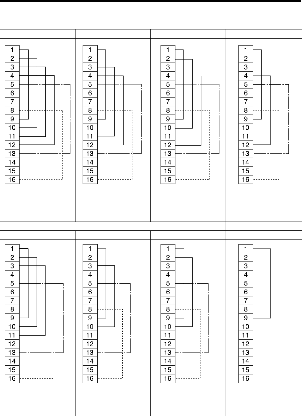
5. POWER SUPPLY EQUIPMENT
RH-981A
97
5-4. Specification harness connections
-02, -12, -52 specifications
<L1> <L2> <L3> <L4>
-02, -12, -52 specifications -00, -01 specifications
<L5> <L6> <L7>
* The dotted lines indicate -12 specifications and the broken lines indicate -52 specifications only.
3535Q
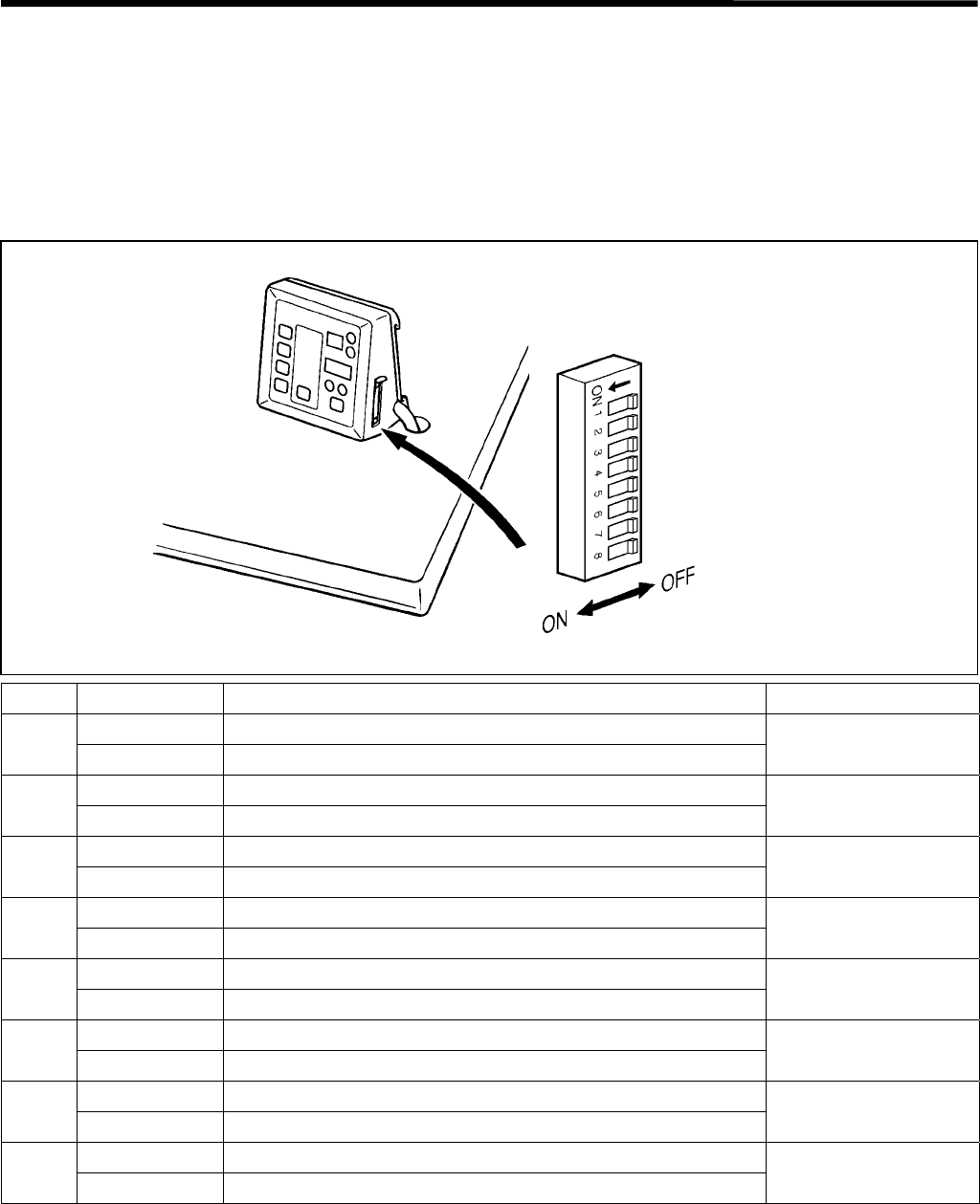
5. POWER SUPPLY EQUIPMENT
RH-981A
98
5-5. Summary of DIP switches
Always turn off the power supply before changing any of the DIP switch settings.
5-5-1. Panel DIP switches
The ON/OFF positions of the DIP switches inside the operation panel are checked only once when the power is
turned on.
Any changes to the DIP switch positions will not be effective until the power is switched off and back on again.
No. ON/OFF Setting items Default
ON Program mode disabled
1* OFF Program mode enabled OFF
ON Switches between taper bar ←→ straight bar tacking
2OFF Normal OFF
ON Set the feed bracket to the front position
3OFF Set the feed bracket to the back position OFF
ON -
4OFF -OFF
ON Single-pedal operation
5OFF Dual-pedal operation OFF
ON -
6OFF - OFF
ON -
7OFF -OFF
ON Maximum stitch width correction amount = 2.0 mm
8** OFF Maximum stitch width correction amount = 1.0 mm OFF
* If program mode is disabled, operation becomes as follows.
• Program numbers, knife operations and the production counter cannot be changed.
• The modes change in the order Automatic → Test feed → Manual → Automatic.
** If the maximum stitch width correction amount is set to 2.0 mm, carry out the adjustment in "9-14. Adjusting the
position of the work clamp plate". If this adjustment is not carried out, the throat plate and needle plate may
interfere with each other.
If the stitch width correction amount is set to more than 1.0 mm, the sewing speed will be limited in accordance
with the value set.
2425Q
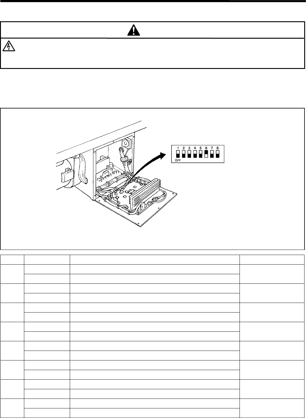
5. POWER SUPPLY EQUIPMENT
RH-981A
99
5-5-2. Circuit board DIP switches
DANGER
Wait at least 5 minutes after turning off the power switch and disconnecting the power cord from the wall
outlet before opening the face plate of the control box. Touching areas where high voltages are present can
result in severe injury.
The ON/OFF positions of the DIP switches inside the control box are checked only once when the power is turned
on.
Any changes to the DIP switch positions will not be effective until the power is switched off and back on again.
Circuit board DIP switch C
No. ON/OFF Setting items Default
ON Special lapel cutting device enabled
1OFF Special lapel cutting device disabled OFF
ON Button hole sensor of special lapel cutting device enabled
2OFF Button hole sensor of special lapel cutting device disabled OFF
ON With pressure sensor
3OFF Without pressure sensor OFF
ON -
4OFF - OFF
ON Upper thread nipper enabled
5OFF Upper thread nipper disabled OFF
ON Lower thread trimming enabled
6OFF Lower thread trimming disabled ON
ON -
7OFF - OFF
ON Maximum straight bar tacking length = 9.0 mm
8* OFF Maximum straight bar tacking length = 6.0 mm OFF
* If the maximum straight bar tacking length is set to 9.0 mm, it will be necessary to process the work clamp plate.
Consult with your local Brother sales office for further details. If the work clamp plate is not processed, the throat
plate may interfere with the needle plate and work clamp plate.
2426Q
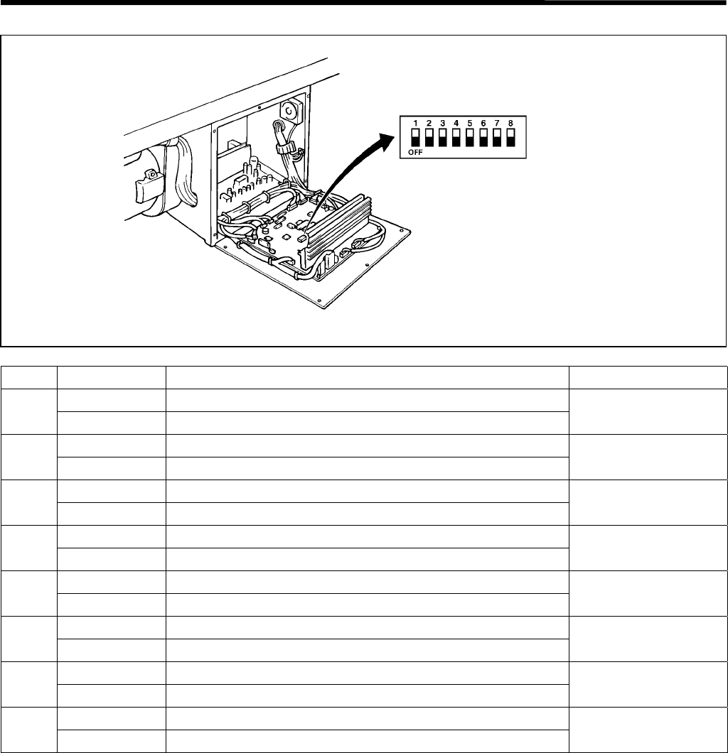
5. POWER SUPPLY EQUIPMENT
RH-981A
100
Circuit board DIP switch D
No. ON/OFF Setting items Default
ON -
1OFF - OFF
ON -
2OFF - OFF
ON -
3OFF - OFF
ON -
4OFF - OFF
ON -
5OFF - OFF
ON -
6OFF - OFF
ON -
7OFF - OFF
ON -
8OFF - OFF
1001Q
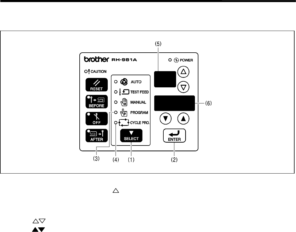
5. POWER SUPPLY EQUIPMENT
RH-981A
101
5-6. CHANGING FUNCTIONS USING THE MEMORY SWITCHES
The memory switches are valid for all programs.
1. Press the SELECT key (1) to change the mode to program or cycle program mode.
2. While pressing the ENTER key (2), press the key.
* The program mode indicator (3) and the cycle program mode indicator (4) will illuminate.
* The memory switch number "00" will appear in the program number display (5), and the memory switch setting
will appear in the detail display (6).
3. Press the keys to select the number for the memory switch to be changed.
4. Press the keys to change the memory switch setting.
* The memory switch setting will flash while it is being changed.
5. Press the ENTER key (2) to accept the new setting.
* The memory switch setting will stop flashing.
6. Repeat steps 3 to 5 to change other memory switch settings.
7. Press the SELECT key (1) to change the mode to automatic mode.
* The memory switch settings will be memorized.
3118Q

5. POWER SUPPLY EQUIPMENT
RH-981A
102
5-6-1. Memory switch table
The memory switch settings are applied immediately to all programs once the settings have been changed.
However, memory switches marked with * are only applied after the power is turned on.
No. Setting items Setting range Unit Default
00. Work clamp down operation when feed bracket is
forward
OFF, ON - OFF
01. Work clamp stays down after sewing OFF, ON - OFF
02. Number of home position start cycles (Note 1) OFF, 1 - 9 1 1
03. Cutting block ON time 25 - 200 ms 25 ms 25 ms
04. Timer for checking raising of hammer
(Timer for determining if the cutting block has been
raised to a position where it will not touch the next
feed bracket to operate)
OFF (Determined
from number of slit
signals),
200 - 500 ms
50 ms OFF
05. Feed operation timing correction after hammer is
raised
(After checking that the hammer is raised, the timer
interval is added so that the hammer and feed
bracket do not touch.)
0 - 150 ms 25 ms 0
06. Test feeding deceleration speed OFF, 1 - 4 1 OFF
07. Increased amount of upper thread remaining OFF, 1 - 3 1 OFF
08. Stitch length display in automatic mode OFF, ON - OFF
09.* Max. stitch length of L7 40 mm, 42 mm 2 mm 40 mm
10. Feed timing correction -10 - 10 1 0
11.* Number of eyelet buttonholes when fly indexer is
used
OFF (Fly indexer is
not used),1 - 9
11
12.* Cloth setting position when fly indexer is used 1: Left setting
position
2: Horizontal setting
position
11
13. Program number selected when buttonhole sensor
is ON when using the special lapel cutting device
OFF, 1 - 9 1 OFF
14. Program number for operating the straight
buttonhole hammer regardless of eyelet shape
setting (parameter No. 01) and whether the
buttonhole sensor is ON or OFF (Note 2)
OFF, 1 - 9 1 OFF
(Note 1) If home position starting is not carried out for each piece of material, there is the danger that the feed
bracket may become overloaded for some reason and come off, which will affect the next piece to be sewn.
Accordingly it is recommended that you set home position starting to be carried out each time (setting "1").
(Note 2) If a program number has been set for memory switch No. 13, it will be ignored if a program number has
been set for memory switch No. 14.
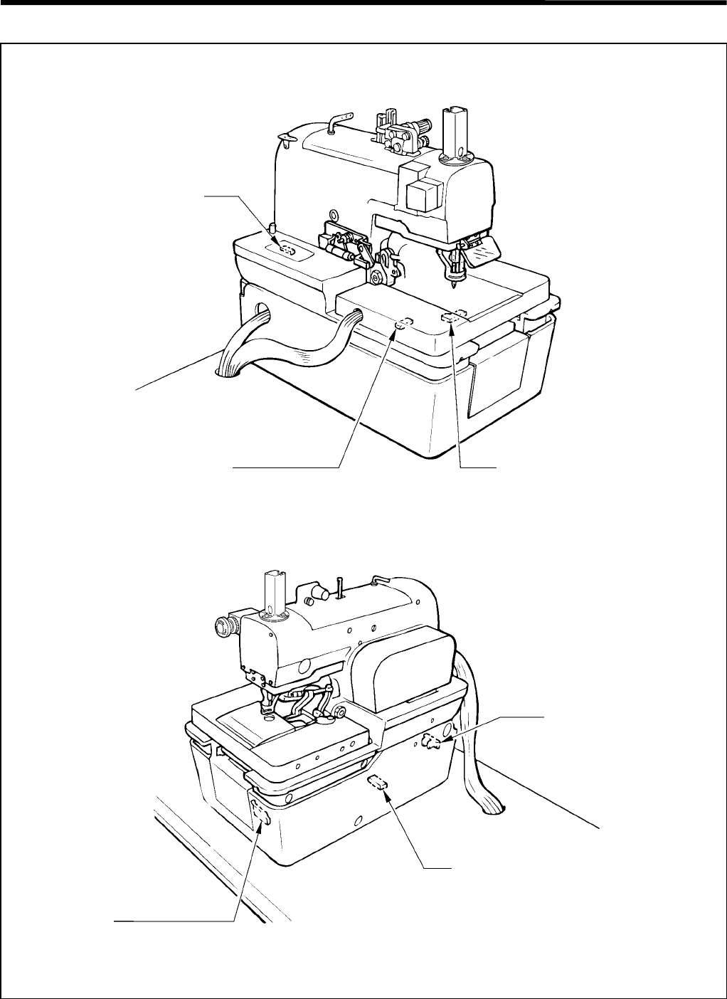
5. POWER SUPPLY EQUIPMENT
RH-981A
103
5-7. Sensors positions and funstions
3536Q
3537Q
Y-axis home position sensor
(magnetic sensor)
Knife ON sensor
(photo sensor)
X-axis home position sensor
(magnetic sensor)
Lower thread trimmer OFF sensor
(cylinder sensor)
Looper base (θ-axis) home position sensor
(magnetic sensor)
Safety sensor
(limit sensor)
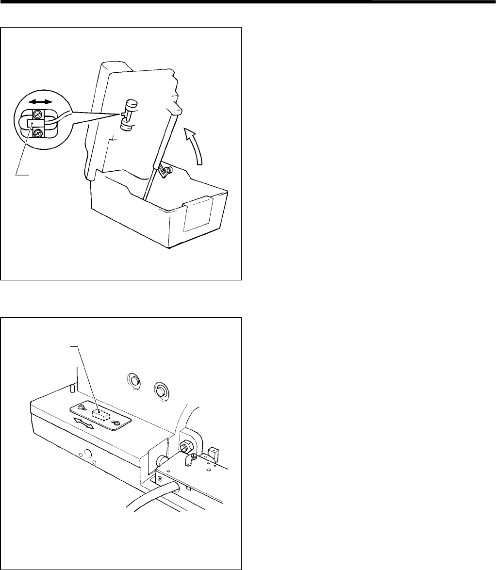
5. POWER SUPPLY EQUIPMENT
RH-981A
104
X-axis home position sensor
• The X-axis home position sensor determines the
home position of the feed bracket in the X direction.
• When the feed bracket is on the left of the head, the
X-axis home position sensor is set to off, and when
right, set to on.
• When the home position is detected, the X-axis home
position sensor is turned on.
• If the X-axis home position sensor is out of order, its
connectors are not attached correctly, or the cord
does not flow electricity, error code E-50 or E-80 will
appear.
Y-axis home position sensor
• The Y-axis home position sensor determines the
home position of the feed bracket in the Y direction.
• The Y-axis home position sensor is set to on only
when the feed bracket is at the home position.
• If the Y-axis home position sensor is out of order, its
connectors are not attached correctly, or the cord
does not supply electricity, error code E-51 or E-81
will appear.
3538Q
3539Q
Y-sensor
X-sensor
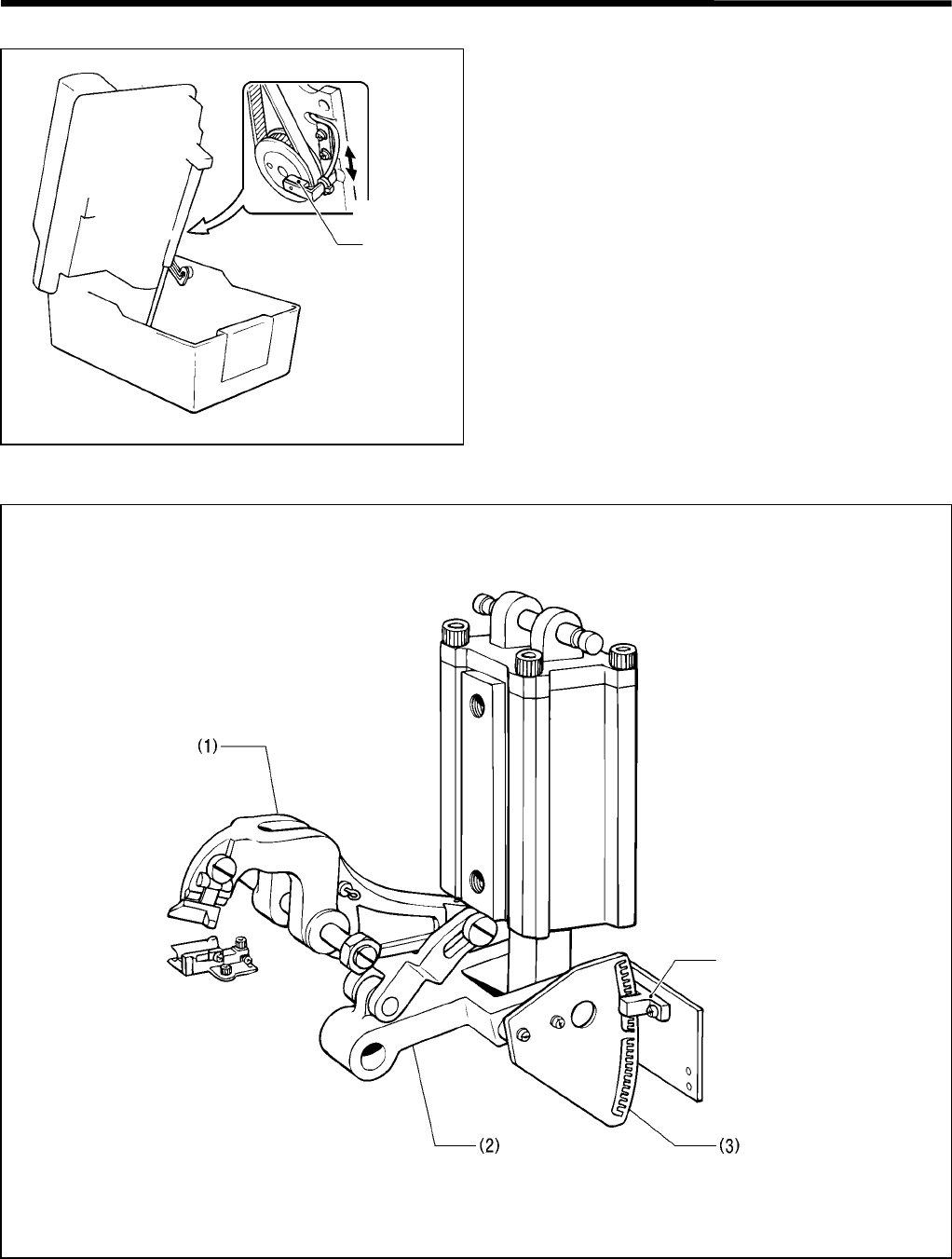
5. POWER SUPPLY EQUIPMENT
RH-981A
105
Looper base home position sensor (θ-axis home position sensor)
• The looper base home position sensor determines
the home position of the looper base (when it is at 0°)
• The looper base home position sensor is set to on
only when the looper base is at the home position.
• If the looper base home position sensor is out of
order, its connectors are not attached correctly, or the
cord does not supply electricity, error code E-52 or E-
82 will appear.
Knife ON sensor
• The knife ON sensor is intended to sense that the operation of the cutter lever (1) has been completed, and to
know the cutter lever (1) lift stroke.
• The cutter sensor partition plate (slit) (3) is attached to link C (2) which moves the cutter lever (1). The signal is
sent from the cutter sensor (4) mounted on the bed.
3540Q
R-sensor
3541Q
Cutter sensor
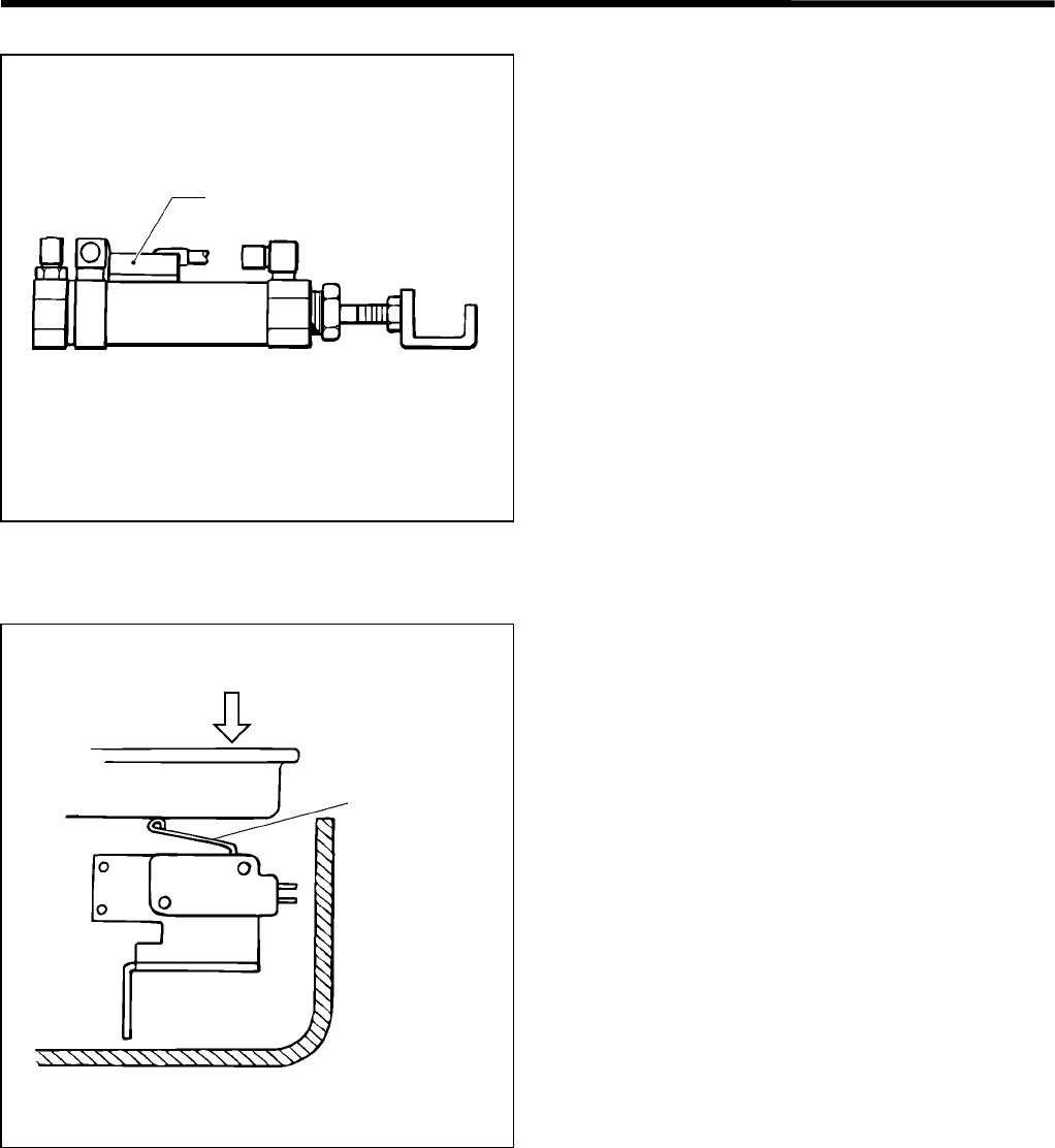
5. POWER SUPPLY EQUIPMENT
RH-981A
106
Lower thread trimmer OFF sensor
• The lower thread trimmer OFF sensor is attached to
the cylinder which drives the lower thread trimmer.
• The lower thread trimmer OFF sensor is intended to
make the lower thread trimmer securely set to off.
• If the lower thread trimmer OFF sensor is out of
control or attached incorrectly, its connectors are not
attached correctly, or the cord does not supply
electricity, error code E-15, E-45, or E-75 will appear.
Safety sensor
• The limit switch is attached to the front of the bed.
• The safety sensor is intended to check that the
machine head is positioned correctly for safe
operation.
• The safety sensor will be activated to stop all motions
when the machine head is raised during sewing.
• If the machine head is kept raised, the safety sensor
is out of control, its connectors are not attached
securely, or the cord does not flow electricity, error
code E-02, E-32, or E-62 will appear.
3542Q
Lower thread trimmer
OFF sensor
3543Q
Safet
y
switch
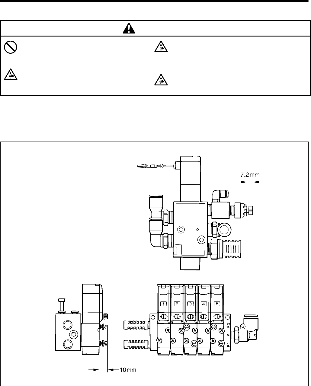
6. AIR PRESSURE MECHANISM
RH-981A
107
6. AIR PRESSURE MECHANISM
CAUTION
Maintenance and inspection of the sewing
machine should only be carried out by a
qualified technician.
Disconnect the air hoses from the air supply and
wait for the needle on the pressure gauge to drop
to “0” before disassembly of any parts which use
the pneumatic equipment.
Turn off the power switch before
disassembly, otherwise the machine may
operate if the start switch is pressed by
mistake, which could result in injury.
If the power switch and air need to be left on when
carrying out some adjustment, be extremely
careful to observe all safety precautions.
6-1. Solenoid valves and air tubes
6-1-1. Adjusting the solenoid valve speed controllers
There are 3 speed controllers: No.3 (for lower thread trimming), No.5 (for upper thread trimming), and one for the knife.
1. As for the No.3 and No.5 speed controllers, adjust their heights to 10 mm.
Note: If the speed controllers are excessively throttled, error codes including E-75 (lower thread and operations
are incorrect) and E-76 (upper thread operation is incorrect), may appears.
2. The exhaust throttle valve is only attached to the OFF side of the knife valve. Adjust the protrusion of the speed
controller to 7.2 mm.
Note: If the speed controllers are excessively throttled, error codes including E-72 (cutting block operation is
incorrect), may appear. If excessively opened, abnormal noise may be emitted when the knife cylinder
returns.
3545Q
3544Q
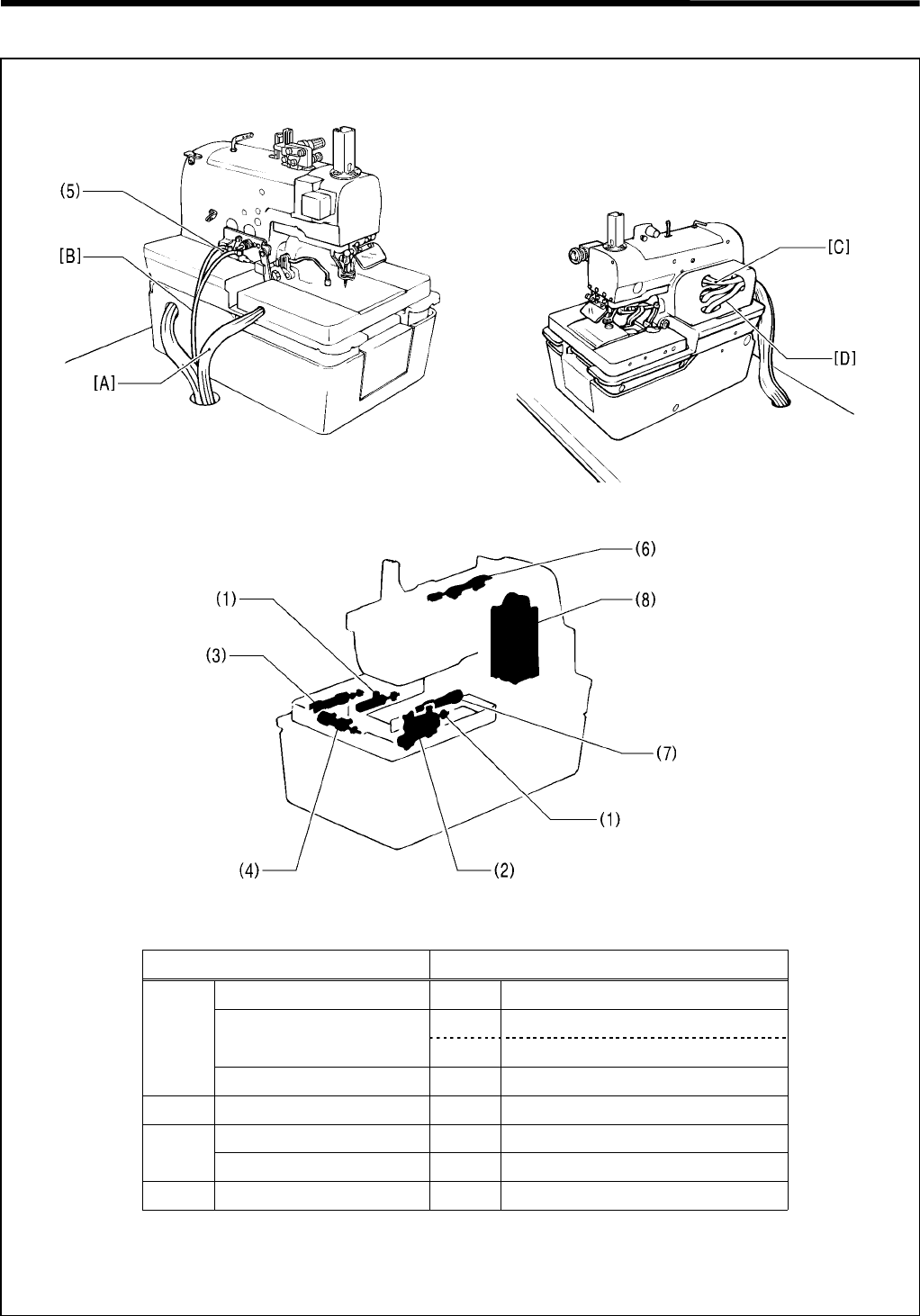
6. AIR PRESSURE MECHANISM
RH-981A 108
6-1-2. Air tubes
3546Q 3547Q
3548Q
Air tubes Cylinders
[A] Work clamp (1) Cylinder, 16X10
Cloth opener (2) Cylinder assembly, A 16X15
(3) Cylinder assembly, B 16X15
Lower thread trimming (4) Cylinder assembly, B 16X30
[B]* Auxiliary clamp (5)* Cylinder assembly, 10X15J
[C] Upper thread tightening (6) Cylinder assembly, 10X15
Upper thread trimming (7) Cylinder assembly, 10X15
[D] Knife (8) Cylinder assembly, 63X100
* -02, -12, -52 specifications only
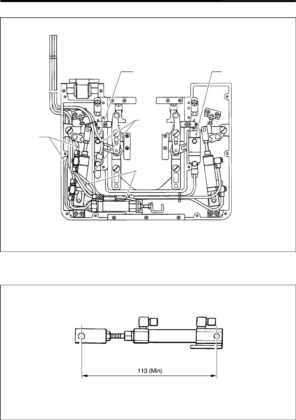
6. AIR PRESSURE MECHANISM
RH-981A
109
6-2. Air tube layout
[Reference] Dimensions for cylinder rod assembly
1. Upper thread release cylinder and sub presser cylinder
3549Q
Work clamp cylinder
For cloth
opener
For work
clam
p
For lower
thread
trimming
Work clamp cylinder
3550Q
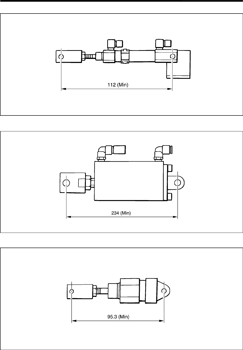
6. AIR PRESSURE MECHANISM
RH-981A 110
2. Upper thread trimming cylinder
3. Cutter cylinder
4. Work clamp cylinder
3553Q
3552Q
3551Q
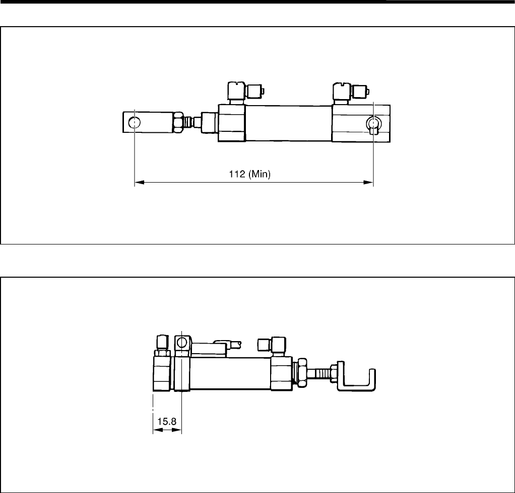
6. AIR PRESSURE MECHANISM
RH-981A
111
5. Cloth opener cylinder
6. Lower thread trimming cylinder
3554Q
3555Q
7. SOFTWARE
RH-981A
112
7. SOFTWARE
7-1. Motion flowchart
Cutting before sewing, back position Cutting after sewing, back position
Start switch ON Start switch ON
↓↓
Hammer operates. Cloth opener operates, and the
upper thread is tightened.
↓↓
Cloth opener operates, and the
upper thread is tightened.
Feed bracket moves to sewing start
position.
↓↓
Feed bracket moves to sewing start
position. Sewing
↓↓
Sewing Upper thread tension is released.
↓↓
Upper thread tension is released. X and Y axes start to return to their
home positions.
↓↓
X and Y axes start to return to their
home positions. Upper thread is trimmed.
↓↓
Upper thread is trimmed. X and Y axes finish returning to their
home positions.
↓↓
X and Y axes finish returning to their
home positions. Hammer operates.
↓↓
Work clamp rises. Work clamp rises and cloth opener
is closed.
↓↓
Cloth opener is closed and lower
thread is trimmed. Lower thread is trimmed.
↓↓
θ axis is returned to home position. θ axis is returned to home position.
↓↓
X, Y, and θ axes each return to
home position (by means of
respective sensors).
X, Y, and θ axes each return to
home position (by means of
respective sensors).
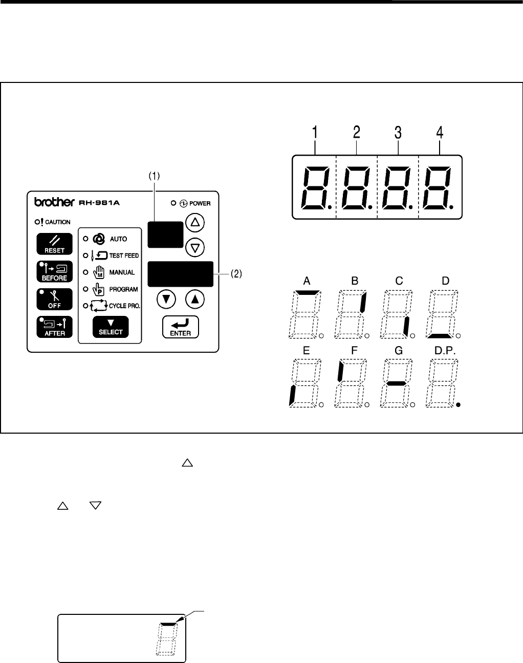
7. SOFTWARE
RH-981A
113
7-2. Input check list
Use the following procedure when checking for switch and sensor breakdown, cord breakage, and adjusting the
sensor positions.
The CPU can be checked as to whether it has correctly interpreted signals from switches and sensors.
1. Turn off the power.
2. Turn on the power while pressing the key.
* The check mode will appear in the program number display (1), and the check result will appear in the detail
display (2).
3. Press the and keys to select a desired check mode (F1 or F2).
4. When the switch or sensor is turned on, the corresponding segment on the detail display (2) or indicators on the
operation panel will react.
* Turn the switch on and off to check it, and move the object by hand to check the sensor.
5. When returning to normal operation, turn power off and then on again.
<Example> When checking the cloth presser switch
Check whether a response occurs here
3558Q
3557Q
3556Q
Segment
Segment meanings
3559Q

7. SOFTWARE
RH-981A
114
No. Check mode Check items Indicator / Segment
1 Detail UP key ( key) Automatic mode indicator
2 Detail DOWN key ( key) Test feed mode indicator
3 ENTER key Manual mode indicator
4 SELECT key Program mode indicator
5 RESET key Cycle program mode indicator
6 BEFORE key BEFORE indicator
7 OFF key OFF indicator
8 AFTER key AFTER indicator
9 Cloth presser switch Segment 4-A
10 Start switch Segment 4-D
11 Needle up signal Segment 4-E
12 Needle down signal Segment 4-F
13 Speed detecting sensor Segment 4-G
14 X-axis home position sensor Segment 3-A
15 Y-axis home position sensor Segment 3-B
16 θ-axis home position sensor Segment 3-C
17 EMERGENCY STOP switch Warning indicator
18 Emergency stop connecting signal Segment 2-A
19 Head sensor Segment 2-B
20 Knife ON sensor Segment 2-C
21 Lower thread trimming OFF sensor Segment 2-D
22 Feed plate home position sensor
(Button hole cloth sensor) Segment 1-A
23 Left driving sensor
(Hammer home position sensor) Segment 1-B
24 Right driving sensor
(Button hole position sensor) Segment 1-C
25
F1
Pressure sensor Segment 1-D
26 Specification harness No.1 Segment 4-D.P
27 Specification harness No.2 Segment 4-G
28 Specification harness No.3 Segment 4-F
29 Specification harness No.4 Segment 4-E
30 Specification harness No.5 Segment 4-D
31 Specification harness No.6 Segment 4-C
32 Specification harness No.7 Segment 4-B
33 Specification harness No.8 Segment 4-A
34 Panel DIP switch No.1 Segment 3-D.P
35 Panel DIP switch No.2 Segment 3-G
36 Panel DIP switch No.3 Segment 3-F
37 Panel DIP switch No.4 Segment 3-E
38
F2
Panel DIP switch No.5 Segment 3-D

7. SOFTWARE
RH-981A
115
No. Check mode Check items Indicator / Segment
39 Panel DIP switch No.6 Segment 3-C
40 Panel DIP switch No.7 Segment 3-B
41 Panel DIP switch No.8 Segment 3-A
42 Circuit board DIP switch C No.1 Segment 2-D.P
43 Circuit board DIP switch C No.2 Segment 2-G
44 Circuit board DIP switch C No.3 Segment 2-F
45 Circuit board DIP switch C No.4 Segment 2-E
46 Circuit board DIP switch C No.5 Segment 2-D
47 Circuit board DIP switch C No.6 Segment 2-C
48 Circuit board DIP switch C No.7 Segment 2-B
49 Circuit board DIP switch C No.8 Segment 2-A
50 Circuit board DIP switch D No.1 Segment 1-D.P
51 Circuit board DIP switch D No.2 Segment 1-G
52 Circuit board DIP switch D No.3 Segment 1-F
53 Circuit board DIP switch D No.4 Segment 1-E
54 Circuit board DIP switch D No.5 Segment 1-D
55 Circuit board DIP switch D No.6 Segment 1-C
56 Circuit board DIP switch D No.7 Segment 1-B
57
F2
Circuit board DIP switch D No.8 Segment 1-A
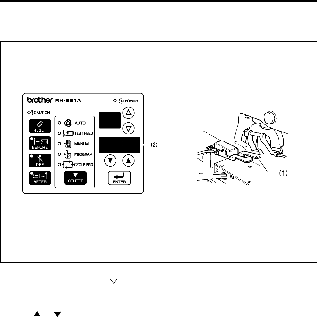
7. SOFTWARE
RH-981A
116
7-3. Output check list
Use the following procedure when checking for PCB-related failures, mechanism breakdown, and cord breakage.
It can be checked as to whether signals that the CPU correctly output have been received.
1. Turn off the power.
2. Turn on the power while pressing the key.
3. Press the start switch (1).
* The machine will start to detect the home position.
* The check code will appear in the detail display (2).
4. Press the and keys to select the desired check code.
5. Press the start switch (1).
* While the start switch is kept pressed, the machine will work as it is specified by each check code.
6. When returning to normal operation, turn power off and then on again.
3560Q 3141Q

7. SOFTWARE
RH-981A
117
Check code Function
C-01
After activating the buzzer for a second, X-, Y-, and θ-home positions are detected when the
machine stops with the needle at its upper limit.
(Head sensor will not conduct any error check.)
C-02 The machine will hold the material.
C-03 The machine will open the material.
C-04 After activating the buzzer for a second, the machine opens the material, turns 180˚ (θ), and
activates lower thread and lower gimp trimmers.
C-05 After activating the buzzer for a second, turns 180˚ (θ), and the upper thread trimmer will be
activated.
C-06 After activating the buzzer for a second, the machine will hold the material and activate the
hammer.
C-07
After activating the buzzer for a second, the machine will hold the material, and operate the
machine motor at 700rpm.
Turn off the start switch to stop the machine.
C-10 Upper thread will be tightened.
C-11
After activating the buzzer for a second, the X feed mechanism will reciprocate in the range of
–6 mm to + 6 mm.
Note: Be sure to remove the work clamp and check the motion of the X feed mechanism.
C-12
After activating the buzzer for a second, the Y feed mechanism will reciprocate in the range of
–1 mm to + 65 mm.
Note: Be sure to remove the work clamp and check the motion of the Y feed mechanism.
C-13
After activating the buzzer for a second, the θ feed mechanism will reciprocate in the range of
–2.7˚ + 362.7˚.
Note: Be sure to remove the work clamp and check the motion of the θ-axis feed mechanism.
C-16 *1 Feed plate is temporarily fixed. (Fixing cylinder on)
C-17 *1 Feed plate is fixed. (Chuck cylinder on)
C-18 *1 Feed plate is moved to the right. (Cloth feed driving cylinder on)
C-19 *2
After the feed bracket moves forward, the hammer plate of the hammer selector assembly
drops.
Note: Be sure to remove the work clamp and check the motion of the hammer plate.
C-20 *3 Upper thread nipper [1] (up/down) turns on.
C-21 *3 Upper thread nipper [2] (open/close) turns on.
C-31 The buzzer sounds.
C-32 All indicators on the operation panel will be lit.
*1 Available only when indexer is attached.
*2 Available only when special lapel cutting device (optional) is attached.
*3 Available only when upper thread nipper (optional) is attached.

7. SOFTWARE
RH-981A
118
7-4. List of error codes
When an error occurs, the warning indicator and the error code display flash and the buzzer sounds.
1. Errors after power is turned on
Code Explanation Resetting method [ I ] Input check No.
[O] Output check code
E-00 EMERGENCY STOP switch was
pressed.
Release the EMERGENCY STOP
switch, and then press the RESET key. [ I ] 17,18
E-02 Machine head is tilted back. Turn off the power. [ I ] 19
E-03 Cloth presser switch was pressed. Release the cloth presser switch, and
press the RESET key. [ I ] 9
E-04 Start switch was pressed. Release the start switch, and press
the RESET key. [ I ] 10
E-05 Air pressure is insufficient. Turn off the power. -
E-06 Feed plate home position sensor is
OFF. Set it to ON. [ I ] 22
E-07 Feed plate left range sensor is OFF. Turn off the power. [ I ] 23
[O]C-18
E-09 Specification that machine does not
support is set. Turn off the power. [ I ] 26 - 33
E-10 Needle bar is not at the highest
position.
Turn the pulley by hand to raise the
needle bar to its highest position. [ I ]11
E-12 Cutter sensor is ON. Turn off the power. [ I ] 20
[O] C-06
E-15 Lower thread trimming OFF sensor is
OFF. Turn off the power. [ I ] 21
[O] C-04
E-26 PER terminal connection error Turn off the power. -
E-27 External RAM error Turn off the power. -
E-28 Panel communication start error Turn off the power. -
E-29 Machine motor communication start
error Turn off the power. -
2. Errors before operation
Code Explanation Resetting method [ I ] Input check No.
[O] Output check code
E-30 EMERGENCY STOP switch was
pressed.
Release the EMERGENCY STOP
switch, and then press the RESET key. [ I ] 17,18
E-32 Machine head is tilted back. Turn off the power. [ I ] 19
E-35 Air pressure is insufficient. Turn off the power. -
E-36 Feed plate home position sensor is
OFF when it should be ON. Turn off the power. [ I ] 22
E-37 Feed plate left range sensor is OFF
when it should be ON. Turn off the power. [ I ] 23
[O] C-18
E-38 Feed plate right range sensor is OFF
when it should be ON. Turn off the power. [ I ] 24
[O] C-18
E-40 Needle up sensor is OFF when it
should be ON.
Turn the pulley by hand to raise the
needle bar to its highest position, and
then press the RESET key.
[ I ] 11
E-42 Cutter sensor is ON. Turn off the power. [ I ] 20
[O] C-06

7. SOFTWARE
RH-981A
119
Code Explanation Resetting method [ I ] Input check No.
[O] Output check code
E-45 Lower thread trimming OFF sensor is
OFF. Turn off the power. [ I ] 21
[O] C-04
E-50 X home position sensor is OFF when
it should be ON. Turn off the power. [ I ] 14
E-51 Y home position sensor is OFF when
it should be ON. Turn off the power. [ I ] 15
E-52 θ home position sensor is OFF when it
should be ON. Turn off the power. [ I ] 16
E-59 Sewing data error Turn off the power. -
3. Errors during operation
Code Explanation Resetting method [ I ] Input check No.
[O] Output check code
E-60 EMERGENCY STOP switch was
pressed.
Release the EMERGENCY STOP
switch, and then press the RESET
key.
-
E-62 Machine head is tilted back. (Head
sensor is OFF.) Turn off the power. [ I ] 19
E-66 Feed plate home position sensor is
not activated within a specified time. Turn off the power. [ I ] 22
E-67 Feed plate left range sensor is not
activated within a specified time. Turn off the power. [ I ] 23
[O] C-18
E-68 Feed plate right range sensor is not
activated within a specified time. Turn off the power. [ I ] 24
[O] C-18
E-70 Needle up sensor is not activated
within a specified time. Turn off the power. [ I ] 11
[O] C-07
E-71 Needle down sensor is not activated
within a specified time. Turn off the power. [ I ] 12
[O] C-07
E-72 Cutter sensor is not activated within a
specified time. Turn off the power. [ I ] 20
[O] C-06
E-75 Lower thread trimming OFF sensor is
not activated within a specified time. Turn off the power. [ I ] 21
[O] C-04
E-76 Needle up sensor is OFF during test
feeding. Turn off the power. [ I ] 11
E-77 Synch signal is not activated within a
specified time. Turn off the power. [ I ] 13
E-80
X home position sensor is not set to
ON within a specified time of
searching home position.
Turn off the power. [ I ] 14
E-81
Y home position sensor is not set to
ON within a specified time of
searching home position.
Turn off the power. [ I ] 15
E-82
θ home position sensor is not set to
ON within a specified time of
searching home position.
Turn off the power. [ I ] 16
E-89 Machine motor reverse operation error Turn off the power. [O] C-07

7. SOFTWARE
RH-981A
120
4. Hardware errors
Code Explanation Resetting method [ I ] Input check No.
[O] Output check code
E-90 Communication error (against
machine motor CPU) Turn off the power. -
E-91 Machine motor running error Turn off the power. [ I ] 11 - 13
[O] C-07
E-92 Abnormal voltage error Turn off the power. -
E-93 Fan (large) lock error Turn off the power. -
E-94 Fan (small) lock error Turn off the power. -
E-95 X motor overcurrent error Turn off the power. -
E-96 Y motor overcurrent error Turn off the power. -
E-97 Control circuit board temperature rise
error Turn off the power. -
E-98 Power supply relay error Turn off the power. -
E-99 Power supply circuit board overcurrent
error Turn off the power. -
5. Errors when the special lapel cutting device is attached
Code Explanation Resetting method [ I ] Input check No.
[O] Output check code
E200
Hammer position sensor does not turn
ON when changing to the straight
buttonhole hammer.
Turn off the power. [ I ] 24
[ I ] C-19
E201
Hammer home position sensor does
not turn ON when changing to the
eyelet buttonhole hammer.
Turn off the power. [ I ] 23
[O] C-19
E202
Buttonhole sensor does not turn ON
when using a straight buttonhole
program.
Press the RESET key. [ I ] 22
E203
Buttonhole sensor does not turn OFF
when using an eyelet buttonhole
program.
Press the RESET key. [ I ] 22

7. SOFTWARE
RH-981A
121
7-5. Troubleshooting
Code Countermeasure
E-00
E-30
1. Release the EMERGECY STOP switch.
2. Check if connector P3 (HEAD) on the control circuit board is securely inserted and if any harness is
broken or short-circuited.
3. With the power turned off, separate connectors P3 (HEAD), and check if continuity between the
following pairs of pins 1 to 3 in the connector on the harness is as follows:
• When the EMERGECY STOP switch is activated, between pins 1 and 2 is opened, and between
pins 2 and 3 is short-circuited.
• When the EMERGECY STOP switch is not activated, between pins 1 and 2 is short-circuited, and
between pins 2 and 3 is opened.
* If the result of continuity test is not acceptable in either case, replace the EMERGECY STOP
switch and its harness.
* Even if the result of continuity test is acceptable, harness may be broken or short-circuited. It may
appear when oscillation occurs.
4. If there is still an error even after replacing the EMERGECY STOP switch, replace the control circuit
board.
E-02
E-32
E-62
1. Return machine head to original position.
2. Adjust safety switch so that it is turned on when machine head is returned to its original position.
3. Check if connector P8 (EXINA) on the control circuit board is securely inserted and if any harness is
broken or short-circuited.
4. With the power turned off, separate connectors P8 (EXINA), and check if continuity between pins 1
and 2 in the connector on the harness is as follows:
• When machine head is raised, between pins 1 and 2 is opened.
• When machine head is in position, between pins 1 and 2 is short-circuited.
* If the result of continuity test is not acceptable in either case, replace the head safety switch and
its harness.
* Even if the result of continuity test is acceptable, harness may be broken or short-circuited. It may
appear when oscillation occurs.
5. If there is still an error even after replacing the head safety switch, replace the control circuit board.
E-03
1. Release the cloth presser switch. (Turn it off.)
2. Check if hand switch (foot switch) connector which is outside the control box is securely inserted.
3. Check if connector P19 (FOOT) on the control circuit board is securely inserted and if any harness is
broken or short-circuited.
4. With the power turned off, separate connectors P19 (FOOT), and check if continuity between pins 3
and 4 in the connector on the harness is as follows:
• When the cloth presser switch is activated, between pins 3 and 4 is short-circuited.
• When the cloth presser switch is not activated, between pins 3 and 4 is opened.
* If the result of continuity test is not acceptable in either case, replace the hand switch (or foot
switch) and its harness.
* Even if the result of continuity test is acceptable, harness may be broken or short-circuited. It may
appear when oscillation occurs.
5. If there is still an error even after replacing the hand switch (foot switch) harness (which is connected
to control circuit board and control box), replace the control circuit board.
E-04
1. Release the start switch. (Turn it off.)
2. Check if hand switch (foot switch) connector which is outside the control box is securely inserted.
3. Check if connector P19 (FOOT) on the control circuit board is securely inserted and if any harness is
broken or short-circuited.
4. With the power turned off, separate connectors P19 (FOOT), and check if continuity between pins 1
and 2 in the connector on the harness is as follows:
• When the start switch is activated, between pins 1 and 2 is short-circuited.
• When the start switch is not activated, between pins 1 and 2 is opened.
* If the result of continuity test is not acceptable in either case, replace the hand switch (or foot
switch) and its harness.
* Even if the result of continuity test is acceptable, harness may be broken or short-circuited. It may
appear when oscillation occurs.
5. If there is still an error even after replacing the hand switch (foot switch) harness (which is connected
to control circuit board and control box), replace the control circuit board.

7. SOFTWARE
RH-981A
122
Code Countermeasure
E-05
E-35
1. Check whether the air pressure is insufficient.
2. Check if the circuit board DIP switch No.3 is set to ON.
* If you are not using the pressure sensor, an error will occur if this DIP switch is set to ON.
3. Check if pins 10 and 11 of the connector P1 (ORG) on the control circuit board is securely inserted.
E-06
E-36
E-66
1. Turn on the feed plate home position sensor (limit switch R) of the indexer. (Place the cloth feed bar
at the left position.)
2. Check and adjust the position of the feed plate home position sensor of the indexer. (Refer to the
instruction manual.)
3. Of connectors relayed to head harness, check if the harness for the feed plate home position sensor
is correctly attached to the connector for the θ-axis home position sensor. (The white harness should
be attached to pin 7, and the black one to pin 12. Refer to the instruction manual.)
* Check if there is a harness in the control box that is broken or short-circuited.
4. Check if connector P9 (EXINB) on the control circuit board is securely inserted and if any harness is
broken or short-circuited.
5. With the power turned off, separate connectors P9 (EXINB), and check if continuity between pins 10
and 11 in the connector on the harnesses is as follows:
• When feed plate home position sensor is activated, between pins 10 and 11 is short-circuited.
• When feed plate home position sensor is not activated, between pins 10 and 11 is opened.
* If the result of continuity test is not acceptable in either case, replace the feed plate home position
sensor and its harness.
* Even if the result of continuity test is acceptable, harness may be broken or short-circuited. It may
appear when oscillation occurs.
6. If there is still an error even after replacing the feed plate home position sensor and the sensor relay
cord (attached to the control circuit board and the relay connector), replace the control circuit board.
E-07
E-37
E-67
1. Make sure that the valve unit of the indexer is supplied with air or wiring is correct.
2. Check and adjust the position of the left driving sensor (limit switch L) of the indexer. (Refer to the
instruction manual.)
3. Of connectors relayed to head harness, check if the harness for the feed plate home position sensor
is correctly attached to the connector for the θ-axis home position sensor. (The white harness should
be attached to pin 10, and the black one to pin 15. Refer to the instruction manual.)
* Check if there is a harness in the control box that is broken or short-circuited.
4. Check if connector P9 (EXINB) on the control circuit board is securely inserted and if any harness is
broken or short-circuited.
5. With the power turned off, separate connectors P9 (EXINB), and check if continuity between pins 1
and 2 in the connector on the harnesses is as follows:
• When left driving sensor is activated, between pins 1 and 2 is short-circuited.
• When left driving sensor is not activated, between pins 1 and 2 is opened.
* If the result of continuity test is not acceptable in either case, replace the left driving sensor and its
harness.
* Even if the result of continuity test is acceptable, harness may be broken or short-circuited. It may
appear when oscillation occurs.
6. If there is still an error even after replacing the left driving sensor and the sensor relay cord (attached
to the control circuit board and the relay connector), replace the control circuit board.
E-09
1. Connect the specification harness that conforms to machine’s specification.
2. Check if all pins are inserted into the connector of the specification harness.
3. Check if the connector for the specification harness which is outside the control box is securely
inserted.
4. Check if connector P4 (TYPE) on the control circuit board is securely inserted and if any harness is
broken or short-circuited.
5. Replace the type cord (harness connected to control circuit board and the control box).
6. Replace the control circuit board with a new one.

7. SOFTWARE
RH-981A
123
Code Countermeasure
E-10
E-40
E-76
1. Turn the pulley manually to set the needle to its highest position. (“UP” will appear on the display.)
2. Check if connector P2 (SYNCHRO) on the control circuit board is securely inserted and if any
harness is broken or short-circuited.
3. With connector P2(SYNCHRO) inserted into the PCB in the input check mode, check the voltage
across pins 4 and 5 from the harness as follows:
• Considering pin 5 as 0V (standard), measure the voltage of pin 4 while turning the pulley
manually. It is normal if the voltage is 0V with the needle at its highest position, and 4 – 5V
everywhere but that position.
* If the result is not acceptable, check how the magnet of the pulley is attached, and if it is correct,
replace the synchronizer.
* Even if the result is acceptable, the harness may be broken or short-circuited. It may appear when
oscillation occurs.
4. When there is no problem with the above, replace the control circuit board.
E-12
E-42
1. Position knife correctly.
2. Make sure that knife driving valve is supplied with air and wiring is correct.
3. Make sure that knife ON sensor and neighboring parts are attached correctly.
4. Check if connector P3 (HEAD) of the control circuit board is inserted and if any harness is broken or
short-circuited.
5. Replace knife ON sensor and its harness.
6. Replace the control circuit board with a new one.
E-15
E-45
E-75
1. Check if cylinder is in place. (Check if air is supplied normally, position is correct, nothing caught on
the cylinder, and so on.)
2. Check if connector P8 (EXINA) on the control circuit board is securely inserted and if any harness is
broken or short-circuited.
3. Replace lower thread trimming OFF sensor and its harness.
4. Replace the control circuit board with a new one.
E-26
1. Check if connector P20 (PER) on the control circuit board is securely inserted and if any harness is
broken or short-circuited.
2. Check if connector P2 (PER) on the power supply circuit board is securely inserted and if any
harness is broken or short-circuited.
3. Replace the power supply circuit board with a new one.
4. Replace the control circuit board with a new one.
E-27
1. Check if ROM chips of the control circuit board or panel circuit board are correctly inserted.
(Check position, orientation, lead clinching, etc.)
2. Replace the panel circuit board with a new one.
3. Replace the control circuit board with a new one.
E-28
1. Check if ROM chips of the control circuit board or panel circuit board are correctly inserted.
(Check position, orientation, lead clinching, etc.)
2. Check if connector P2 (MAIN) on the panel circuit board is securely inserted and if any harness is
broken or short-circuited.
3. Check if connector P18 (PANEL) on the control circuit board is securely inserted and if any harness
is broken or short-circuited.
4. Replace the panel circuit board with a new one.
5. Replace the control circuit board with a new one.
E-29
1. Make sure that ROM chips of the control circuit board are correctly inserted. (Check position,
orientation, lead clinching, etc.)
2. Replace the control circuit board with a new one.
E-38
E-68
1. Check if air is supplied to valve unit of the indexer or wiring is correct.
2. If the cloth feed bar of the indexer works correctly, skip to step 5 below. (This is because the place to
be checked is different if the failure is with the sensor or driving system.)
3. Check if the valve harness of the indexer is connected to the indexer relay cord and connector P21
(EXOUT) on the control circuit board.
* Check if there is no pin that is out of place in either of indexer relay connector and P21.
4. Check if feed plate works in output check.
5. Of connectors relayed to head harness, check if the harness for the right driving sensor (cylinder
sensor) is correctly attached to the connector for the θ-axis home position sensor. (The brown
harness should be attached to pin 4, the black one to pin 9, and the blue one to pin 14. Refer to the
instruction manual.)
* Check if there is no harness in the control box that is broken or short-circuited.
6. Check if connector P9 (EXINB) on the control circuit board is securely inserted and if any harness is
broken or short-circuited.
7. Replace the right driving sensor and its harness.
8. Replace the control circuit board with a new one.

7. SOFTWARE
RH-981A
124
Code Countermeasure
E-50
1. Turn power off and then on again. Press start switch to search home position again.
2. Make sure that X-axis home position sensor and X-axis home position sensor magnet are correctly
attached.
3. Check if connector P1 (ORG) on the control circuit board is correctly inserted and if any harness is
broken or short-circuited.
4. Replace X-axis home position sensor and its harness.
5. Replace the control circuit board with a new one.
E-51
1. Turn power off and then on again. Press start switch to search home position again.
2. Make sure that Y-axis home position sensor and Y-axis home position sensor magnet are correctly
attached.
3. Check if connector P1 (ORG) on the control circuit board is correctly inserted and if any harness is
broken or short-circuited.
4. Replace Y-axis home position sensor and its harness.
5. Replace the control circuit board with a new one.
E-52
1. Turn power off and then on again. Press start switch to search home position again.
2. Make sure that θ-axis home position sensor and θ-axis home position sensor magnet are correctly
attached.
3. Check if the θ-axis home position sensor pulley is loosened.
4. Of connectors relayed to head harness, check if the harness for the θ-axis home position sensor is
correctly attached to the connector for the θ-axis home position sensor. (The brown harness should
be attached to pin 1, the black one to pin 6, and the blue one to pin 11. Refer to the instruction
manual.)
* Check if there is a harness in the control box that is broken or short-circuited.
5. Check if connector P9 (EXINB) on the control circuit board is correctly inserted and if any harness is
broken or short-circuited.
6. Replace the θ-axis home position sensor and its harness with a new one.
7. Replace the control circuit board with a new one.
E-59
1. Turn on the power again.
2. Make sure that ROM chips of the panel circuit board are correctly inserted. (Check position,
orientation, lead clinching, etc.)
3. Initialize memory.
4. Replace the panel circuit board with a new one.
E-60
1. This is not an error. This code indicates machine operation is being suspended due to emergency
stop.
2. Refer to the instruction manual, “Using the EMERGENCY STOP switch.” (Press the RESET switch
to return to home position, and the start switch to resume sewing.)
E-70
1. Turn the pulley manually to see if the upper shaft is not locked.
2. In input mode, turning the pulley manually, check the machine detects needle up signal. If not, refer
to E10. Even if it does, synchronizer harness may be broken or short-circuited. It may appear when
oscillation occurs.
3. With the power turned off, separate connectors P15 (DC300) on the control circuit board, and check
if between pins 1 and 2 in the connector on the board is short-circuited. If it is short-circuited, replace
the control circuit board. At this time, if fuse No.2 on the power supply circuit board has been blown,
replace it.
E-71 Refer to E70. (In input mode, check if the machine detects needle down signal.)
E-72
1. If the knife works correctly, refer to E12. If not, proceed the following steps to check the knife driving
system. (This is because the place to be checked is different if the failure is with the sensor or driving
system.)
2. Make sure that air is supplied to knife valve unit.
3. Check if there is a broken valve cord around valve unit.
4. Check if connector P4 (AIR) of the control circuit board is correctly inserted and if valve cord is
broken or short-circuited.
5. Replace valve cord with a new one.
6. Replace valve unit with a new one.
7. Replace the control circuit board with a new one.

7. SOFTWARE
RH-981A
125
Code Countermeasure
E-77 Refer to E70. (In input mode, check if the machine detects synchronizer signal.)
E-80
1. If X-axis pulse motor works, refer to E50. If not, proceed with the following steps to examine the
driving system of the X-axis pulse motor. (This is because the place to be checked is different if the
failure is with the sensor or driving system.)
2. With the power turned off, check if there is a loose screw in a belt or gear around the X-axis pulse
motor and that the feed bracket can move to the left and right.
3. Of the connectors relayed to the head harness, check if the connector for the X-axis pulse motor is
securely inserted and if any harness is broken or short-circuited.
4. Check if connector P7 (XPM) on the control circuit board is securely inserted and if any harness is
broken or short-circuited.
5. While E80 is displayed, measure the voltage across pins 5 and 7 of connector P12 (POWER)
without removing P12, from the harness, as follows:
• Considering pin 7 as 0V (standard), measure the voltage of pin 5. It is normal if the voltage is +
55V. (Be careful not to touch any other place when measuring voltage.)
* If the voltage is + 55V, the cause of the error is the X-axis pulse motor or its harness is broken.
* If the voltage is not + 55V, turn off the power, remove connector P12 (POWER), and then turn on
the power again, measure the voltage across pins 5 and 7 in the harness with connector P1
(POWER) inserted in the power supply circuit board in the same manner as above.
• If the voltage is not + 55V, replace the power supply circuit board.
* If the voltage is + 55V, the control circuit board or PMD circuit board for θ-axis may be damaged
or X-, Y-, or θ-axis pulse motor or its harness may be short-circuited.
E-81
1. If the Y-axis pulse motor works refer to E51. If not, proceed the following steps to examine the
driving system of Y-axis pulse motor. (This is because the place to be checked is different if the
failure is with the sensor or driving system.)
2. With the power turned off, check if there is a loose screw in a belt or gear around Y-axis pulse motor
and if the feed bracket can move back and forth.
3. Of the connectors relayed to the head harness, check if the connector for the Y-axis pulse motor is
securely inserted and if any harness is broken or short-circuited.
4. Check if connector P6 (YPM) on the control circuit board is securely inserted and if any harness is
broken or short-circuited.
5. While E81 is displayed, measure the voltage across pins 5 and 7 of connector P12 (POWER) on the
control circuit board without removing P12, from the harness, as follows:
• Considering pin 7 as 0V (standard), measure the voltage of pin 5. It is normal if the voltage is +
55V, (Be careful not to touch any other place when measuring voltage.)
* If the voltage is + 55V, the cause of the error is the Y-axis pulse motor or its harness is broken.
* If the voltage is not + 55V, turn off the power, remove connector P12 (POWER) from the control
circuit board, and then turn on the power again, and measure the voltage across pins 5 and 7 in
the harness with connector P1 (POWER) inserted in the power supply circuit board in the same
manner as above.
• If the voltage is not + 55V, replace the power supply circuit board.
* If the result is acceptable, the control circuit board or PMD circuit board for θ-axis may be
damaged or X-, Y-, or θ-axis pulse motor or its harness may be short-circuited.
E-82
1. If the θ-axis pulse motor works, refer to E52. If not, proceed the following steps to examine the
driving system of θ-axis pulse motor. (This is because the place to be checked is different if the
failure is with the sensor or driving system.)
2. With the power turned off, check if there is a loose screw in a belt or gear around θ-axis pulse motor
and if the feed bracket can move back and forth.
3. Of the connectors relayed to the head harness, check if the connector for the θ-axis pulse motor is
securely inserted and if any harness is broken or short-circuited.
4. Check if connectors P1 (RPM), P2 (DC55), and P3 (CONTROL) on the PMD circuit board for the θ-
axis are securely inserted and if any harness is broken or short-circuited.
5. Check if connectors P11 (HATOME) and P13 (DC55) on the control circuit board are securely
inserted and if any harness is broken or short-circuited.
6. While E82 is displayed, measure the voltage across pins 5 and 7 of connector P12 (POWER) on the
control circuit board without removing P12, from the harness, as follows:
• Considering pin 7 as 0V (standard), measure the voltage of pin 5. It is normal if the voltage is +
55V. (Be careful not to touch any other place when measuring voltage.)
* If the voltage is + 55V, the cause of the error is the θ-axis pulse motor or its harness is broken.
* If the voltage is not + 55V, turn off the power, remove connector P12 (POWER), and then turn on
the power again, and measure the voltage across pins 5 and 7 in the harness with connector P1
(POWER) inserted in the power supply circuit board in the same manner as above.
• If the voltage is not + 55V, replace the power supply circuit board.
* If the result is acceptable, the control circuit board or PMD circuit board for θ-axis may be
damaged or X-, Y-, or θ-axis pulse motor or its harness may be short-circuited.

7. SOFTWARE
RH-981A
126
Code Countermeasure
E-89
1. Check if the upper shaft motor wiring (U/V/W) is correct.
2. Check if connector P14 (UVW) on the control circuit board is inserted and that the harness-side
wiring is correct.
E-90
1. Check if connector P2 (MAIN) on the panel circuit board is securely inserted and if any connector is
broken or short-circuited.
2. Check if connector P18 (PANEL) on the control circuit board is securely inserted and if any
connector is broken or short-circuited.
3. Replace the panel circuit board with a new one.
4. Replace the control circuit board with a new one.
E-91 Refer to E70. (In input mode, check if the machine detects synchronizer signal.)
E-92
1. Make sure that power supply voltage is the same as the specification voltage.
2. If the conversion transformer is installed, check if terminals connections are correct.
3. Check if connector P20 (PER) on the control circuit board is securely inserted and if any harness is
broken or short-circuited.
4. Check if connector P2 (PER) on the power supply circuit board is securely inserted and if any
harness is broken or short-circuited.
5. Replace the power supply circuit board with a new one.
6. Replace the control circuit board with a new one.
E-93
1. Make sure that the large cooling fan is normally running.
2. Clean the large cooling fan. (Remove dust.)
3. Check if connector P10 (FAN-R) on the control circuit board is securely inserted and if any harness
is broken or short-circuited.
4. Replace the large cooling fan with a new one.
5. Replace the control circuit board with a new one.
E-94
1. Make sure that the small cooling fan is normally running.
2. Clean the small cooling fan. (Remove dust.)
3. Check if connector P25 (FAN-L) on the control circuit board is securely inserted and if any harness is
broken or short-circuited.
4. Replace the small cooling fan.
5. Replace the control circuit board with a new one.
E-95
1. With the power turned off, check if the feed bracket moves to the left and right.
2. Of the connectors relayed to the head harness, check if the connector for the X-axis pulse motor is
securely inserted and if any harness is broken or short-circuited.
3. Check if connector P7 (XPM) on the control circuit board is securely inserted and if any harness is
broken or short-circuited.
4. Replace the X-axis pulse motor with a new one.
5. Replace the control circuit board with new one.
E-96
1. With the power turned off, check if the feed bracket moves back and forth smoothly.
2. Of the connectors relayed to the head harness, check if the connector for the Y-axis pulse motor is
securely inserted and if any harness is broken or short-circuited.
3. Check if connector P6 (YPM) on the control circuit board is securely inserted and if any harness is
broken or short-circuited.
4. Replace the Y-axis pulse motor with a new one.
5. Replace the control circuit board with new one.
E-97
1. Make sure that the control box is normally ventilated.
2. Clean the filter of the air intake. (Remove dust.)
3. Clean the small and large cooling fans (Remove dust.)
4. Make sure that cooling fans are attached correctly.
• Large cooling fan: The wind blows toward the control circuit board and the PMD circuit board for
θ-axis.
• Small cooling fan: The wind blows in the direction that it can discharge the air in the control box.
E-98
1. Check if connectors P12 (POWER) and P13 (DC55) on the control circuit board are securely
inserted and if any harness is broken and short-circuited.
2. Check if connector P1 (POWER) on the power supply circuit board is securely inserted and if any
harness is broken or short-circuited.
3. Check if connector P2 (DC55) on the PMD circuit board for θ-axis is securely inserted and if any
harness is broken or short-circuited.
4. Replace the power supply circuited board with a new one.
5. Replace the PMD circuit board for θ-axis with a new one.
6. Replace the control circuit board with a new one.
E-99 1. Refer to E95, E96 and E98.
2. Replace the power supply circuit board with a new one.

7. SOFTWARE
RH-981A
127
Code Countermeasure
E-200
1. Check if air is supplied to valve unit of the special lapel cutting device or wiring is correct.
2. Of connectors relayed to head harness, check if the harness for the hammer position sensor is
correctly attached to the connector for the hammer position sensor.
* Check if there is no harness in the control box that is broken or short-circuited.
3. Check if connectors P9 (EXINB) and P21 (EXOUT) on the control circuit board are securely
inserted and if any harness is broken or short-circuited.
E-201
1. Check if air is supplied to valve unit of the special lapel cutting device or wiring is correct.
2. Of connectors relayed to head harness, check if the harness for the hammer home position sensor
is correctly attached to the connector for the hammer home position sensor.
* Check if there is no harness in the control box that is broken or short-circuited.
3. Check if connectors P9 (EXINB) and P21 (EXOUT) on the control circuit board are securely
inserted and if any harness is broken or short-circuited.
E-202
E-203
1. Press the RESET key.
2. Of connectors relayed to head harness, check if the harness for the buttonhole sensor is correctly
attached to the connector for the buttonhole sensor.
* Check if there is no harness in the control box that is broken or short-circuited.
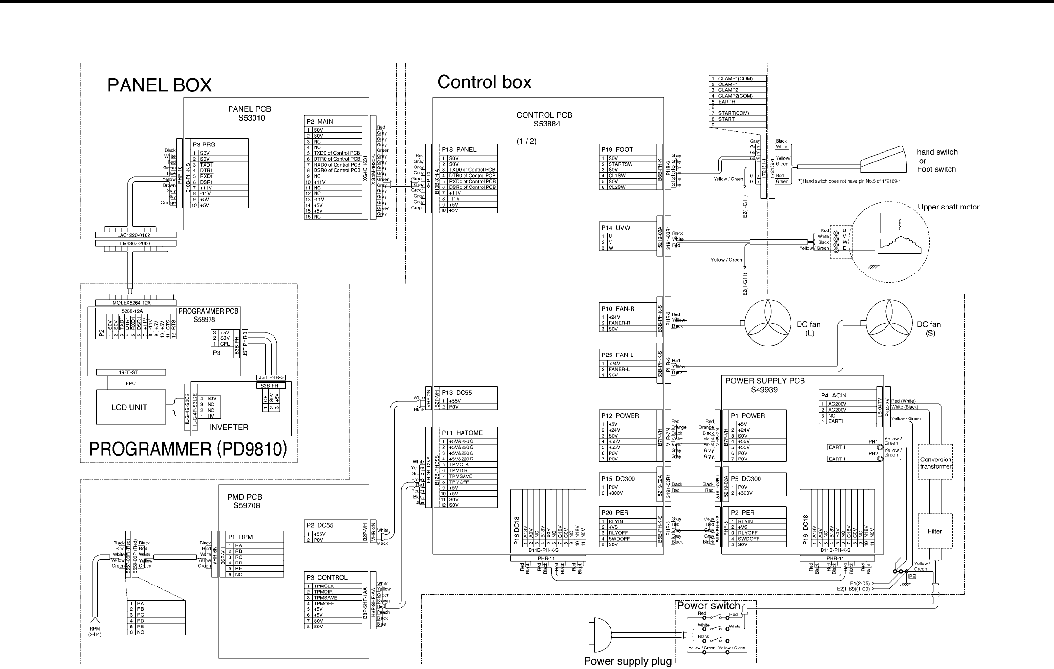
7. SOFTWARE
RH-981A 128
7-6. Control circuit block diagram (1)
3842Q
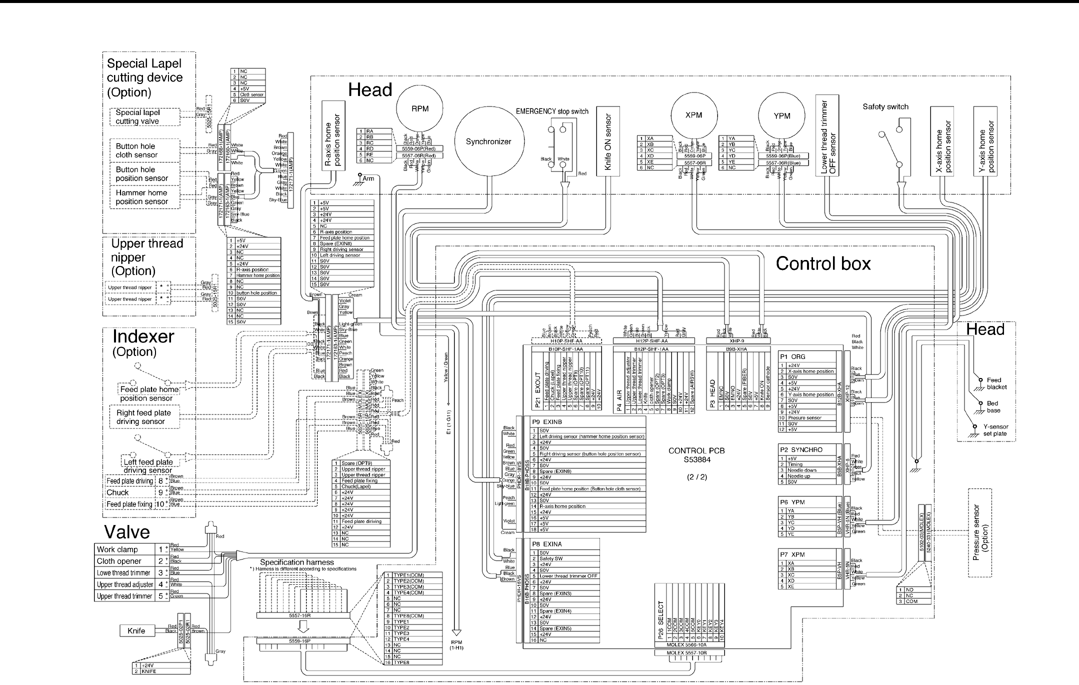
7. SOFTWARE
RH-981A 129
7-7. Control circuit block diagram (2)
3843Q

SERVICE MANUAL
Printed in Japan RH-981
A
I3080846H
2003.10. H (1)
http://www.brother.com/
