ACE&EASTMAN Sc 510 Eg Instruction Manual (ENGLISH) User
Sc-510-Eg SC-510-EG SC-510-EG JUKI INSTRUCTION MANUALS a.teamworksales.com
2016-09-15
User Manual: ACE&EASTMAN Sc-510-Eg Instruction Manual
Open the PDF directly: View PDF ![]() .
.
Page Count: 39
- COVER
- CONTENTS
- I. SPECIFICATIONS
- II. SET-UP
- III. FOR THE OPERATOR
- 1. Operation of SC-510
- 2. Explanation of the operation panel
- 3. Setting for functions of SC-510
- 4. Function setting list
- 5. Detailed explanation of selection of functions
- 6. Automatic compensation of neutral point of the pedal sensor
- 7. Setting of the auto lifter function
- 8. Initialization of the setting data
- IV. MAINTENANCE

ENGLISH
INSTRUCTION MANUAL
CONTENTS
!. SPECIFICATIONS ................................................................... 1
@. SET-UP .................................................................................... 1
1. Installing the motor unit ........................................................................................ 1
2. Installing the control box ...................................................................................... 1
3. Installing the belt.................................................................................................... 2
4. Adjusting the pulley cover .................................................................................... 2
5. Installation and adjustment for the protecting pin
and the belt slip-off preventing bracket ............................................................... 3
6. Connecting the cords ............................................................................................ 4
7. Attaching the connecting rod ............................................................................... 10
#. FOR THE OPERATOR ............................................................ 11
1. Operation of SC-510............................................................................................... 11
2. Explanation of the operation panel ...................................................................... 12
3. Setting for functions of SC-510 ............................................................................ 17
4. Function setting list ............................................................................................... 19
5. Detailed explanation of selection of functions.................................................... 23
6. Automatic compensation of neutral point of the pedal sensor ......................... 32
7. Setting of the auto lifter function.......................................................................... 32
8. Initialization of the setting data ............................................................................ 33
$. MAINTENANCE ...................................................................... 33
1. Replacing the fuse ................................................................................................. 33
2. Changing procedure between 100V to 120V and 200V to 240V
(Possible only for the voltage changeover type) ................................................ 35
3. Error codes ............................................................................................................. 36
− 1 −
!. SPECIFICATIONS
@. SET-UP
Install the motor unit to the control box following the instructions below.
Supply voltage Single phase 100 to 120V / 3-phase 200 to 240V Single phase 200 to 240V
Frequency 50 Hz / 60 Hz 50 Hz / 60 Hz
Operating environment Temperature : 0 to 40˚C Temperature : 0 to 40˚C
Humidity : 90% or less Humidity : 90% or less
Power consumption 425VA 425VA
1
2
3
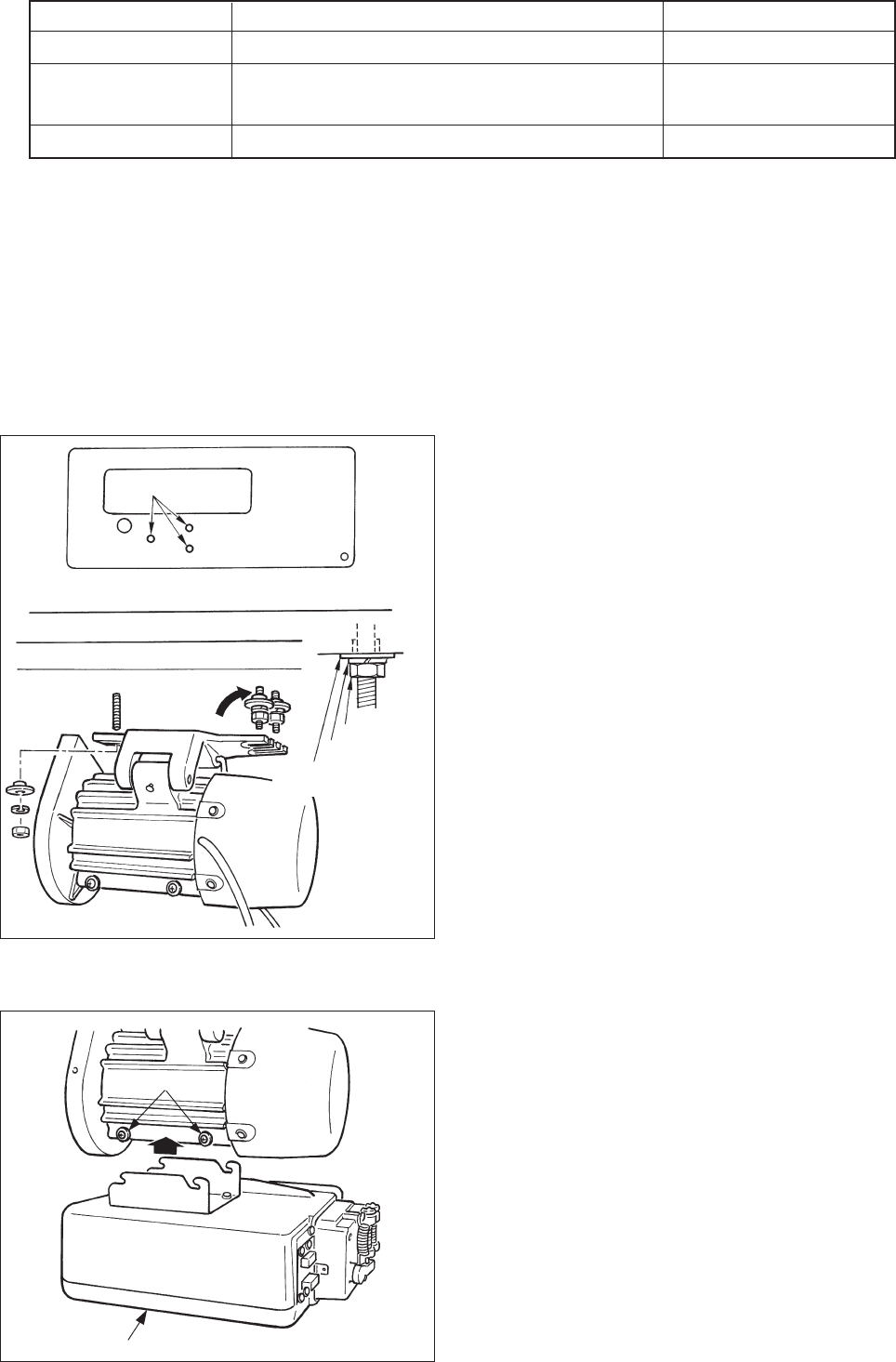
1. Installing the motor unit
Install the motor unit on the table with the fitting bolt
asm. supplied with the unit as accessories.
At this time, insert the nuts and washers supplied with
the unit as accessories as shown in the figure so that
the motor unit can be securely fixed on the table.
1) Press three bolts 1 supplied with the unit as
accessories into the motor hanging bolt hole in the
table and fix them.
2) Temporarily tighten convex washer, spring washer
and nut on the side where two bolts are attached.
3) Hang the motor unit to the washer which has been
temporarily tightened, and attach convex washer,
spring washer and nut to the other bolt on the
opposite side.
4) After adjusting the installing position of the motor,
securely tighten the respective nuts.
2. Installing the control box
1) Loosen four screws 2 supplied with the motor unit
as accessories, tighten screws 2 after hanging
control box unit 3 to the screws, and fix control
box unit 3.
Spring
washer
Nat
Convex
washer
(Caution) 1. Indication of the power consumption is the mean power consumption when LU-1520N-
7 is mounted in accordance with the operating conditions JUKI specifies.The power
consumption changes in accordance with the operating conditions and the mounted
machine head. So, be careful.
2. Instantaneous maximum power consumption may become 1.5 times or more than the
mean power consumption.
− 2 −
15mm (9.8N)
a
b
1
1
2
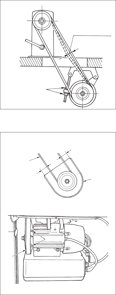
3. Installing the belt
1) The belt distance, between sewing machine pulley
and motor pulley, must be parallel.
2) The belt tension should be adjusted by turning the
tension adjust nuts to change height of the motor,
so that the belt sinks down by about 15 mm (9.8N)
when it is depressed by band at the center of the
belt span.
If the belt tension is not tight, speed is unstable at
low-speed or medium-speed operation, and the
needle will not stop exactly in position.
4. Adjusting the pulley cover
1) After adjusting the belt tension, adjust the pulley
cover 1 so that the clearances between the belt
and the pulley cover 1, a and b should be the
same.
2) After the completion of adjustment, tighten screws
2 located on the side of pulley cover 1 and
securely fix the pulley cover 1 so that it does not
slip out of position.
Tension
adjust nuts
Belt
− 3 −
AB
Belt
1
23
4
5
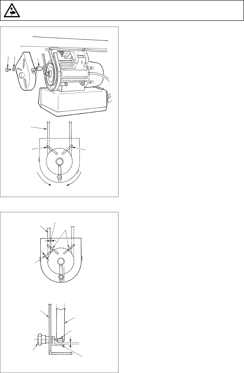
1
1) Attaching hole for the protecting pin
To attach protecting pin 1, select either attaching
hole A or attaching hole B in the motor pulley cover
in accordance with the direction of rotation of the
sewing machine and attach the pin in the selected
hole using screw 2 and washer 3 supplied with
the unit.
a) If the motor shaft rotates in direction A in the
figure on the above:
/ Attach protecting pin 1 in attaching hole A .
b) If the motor shaft rotates in direction B in the
figure on the above:
/ Attach protecting pin 1 in attaching hole B .
2) Adjustment for the protecting pin and the belt slip-
off preventing bracket
Adjust the position of protecting pin 1 and belt slip-
off preventing bracket 4 in accordance with the
figure on the left.
a) Adjusting the protecting pin
Loosen screw 2 and adjust so that protecting
pin 1 is positioned at the location indicated in
the figure on the left.
b) Adjusting belt slip-off preventing bracket
Loosen screw 5 and adjust so that belt slip-
off preventing bracket 4 is positioned at the
location indicated in the figure on the left.
If protecting pin 1 is not properly adjusted, it
is possible that your fingers may be caught in
the clearance provided between the pulley and
the belt resulting in injury. If belt slip-off
preventing bracket 4 is not properly adjusted,
it is possible to allow the belt to slip off causing
safety hazard.
3) After the adjustment, tighten screws 2 and 5 so
as to secure protecting pin 1 and belt slip-off
preventing bracket 4 to prevent these components
to fluctuate because of vibration.
4) Before starting the operation of the sewing
machine, ascertain that protecting pin 1 and belt
slip-off preventing bracket 4 do not come in contact
with the pulley and the belt.
5. Installation and adjustment for the protecting pin and the belt slip-off preventing bracket
WARNING :
To protect against possible personal injury due to abrupt start of the machine, be sure to start the
following work after turning the power off and ascertaining that the motor is at rest.
4 mm or less
Belt
4 mm or less
Adjusting position for protecting pin
Pulley
cover Motor
pulley
Belt
3 mm or less
Adjusting position for belt slip-off preventing braket
Attaching
hole A
Attaching
hole B
− 4 −
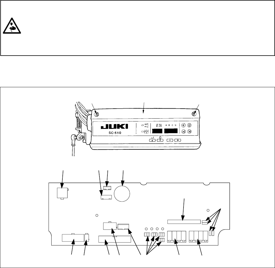
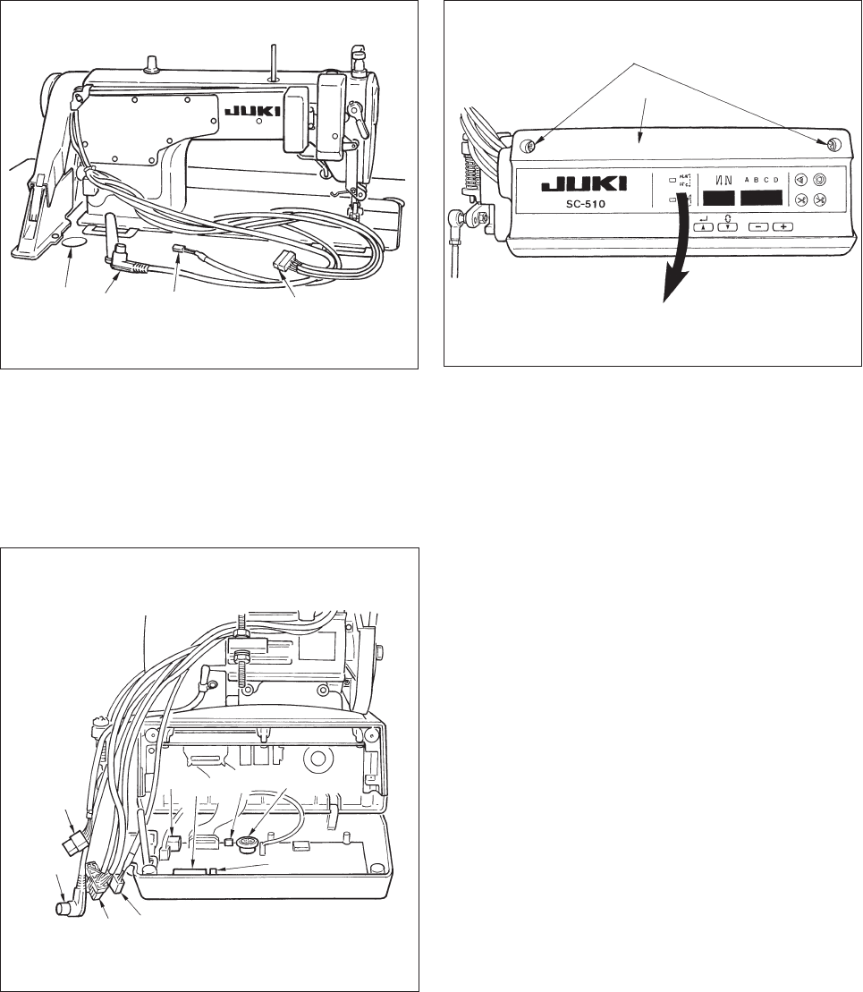
Following connectors are prepared when loosening the front cover fixing screws A of SC-510 and opening the
cover. Connect the machine head connectors to the positions corresponding to each other so as to fit the
devices mounted on the machine head.
WARNING :
•To prevent personal injury caused by abrupt start of the sewing machine, carry out the work after
turning OFF the power switch and a lapse of 5 minutes or more.
•To prevent damage of device caused by maloperation and wrong specifications, be sure to connect
all the corresponding connectors to the specified places.
• To prevent personal injury caused by maloperation, be sure to lock the connector with lock.
•As for the details of handling respective devices, read carefully the Instruction Manuals supplied
with the devices before handling the devices.
6. Connecting the cords
1CN30 Motor signal connector
2CN43 Needle bar position detector connector (+12V type)
3CN32 Machine head connector
4CN33 Needle bar position detector connector (+5V type)
5CN36 Machine head solenoid connector
6CN37 Presser foot lifter solenoid connector
7CN38 CP-160 panel connector
8CN40 Signal for extension output connector (For the details, refer to Engineer's Manual.)
9W1, W2,
W3, W4 Optional jumper pins for changeover of input/output of power source (For the details, refer to
Engineer's Manual.)
!0 CN50 Optional output connector (For the details, refer to Engineer's Manual.)
!1 CN51 Optional input connector (For the details, refer to Engineer's Manual.)
!2 CN41 Connector for extension p.c.b. (For the details, refer to Engineer's Manual.)
!3 W5 to W8 Jumpers for optional input changeover (For the details, refer to Engineer's Manual.)
!4 CN39 Pedal for standing work connector (PK-70 and the like can be used.)
Front cover
AA
9
231 4
57
!2
!3
68 !1
!0
!4
− 5 −
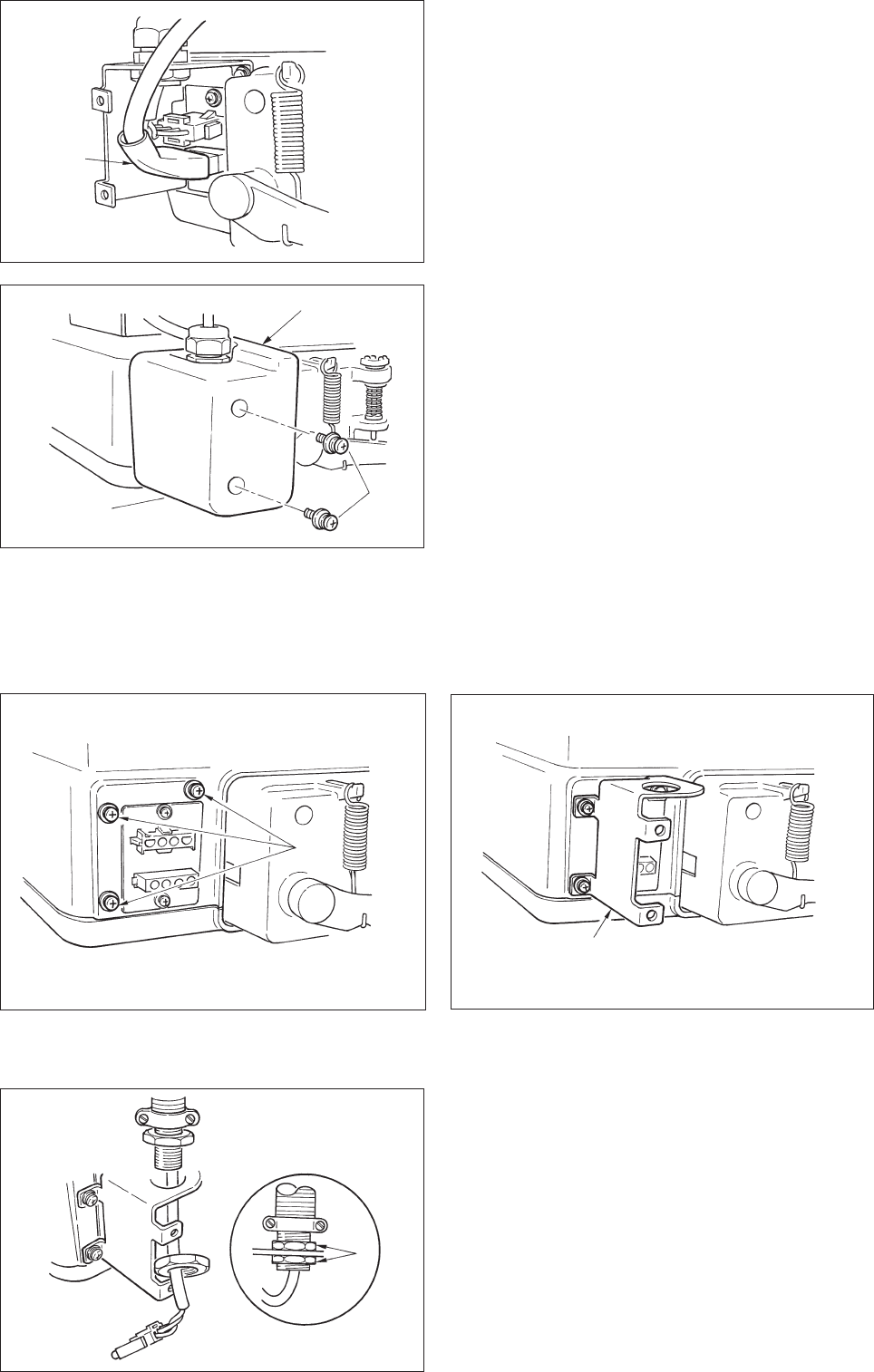
2) Loosen setscrew 5 in front cover 4.
3) Pressing the side of front cover 4 in the direction
of the arrow, open the front cover toward you.
Note : Be sure to open / close the front cover with
your hands.
4) Connect 14P code 1 coming from the machine
head to connector 7 (CN36).
5) Connect 4P connector coming from the machine
head 3 to connector 8 (CN32).
6) Connect 7P connector 2 coming from the machine
head to connector 9 (CN33).
7) When the optional AK device is attached, connect
2P connector coming from the AK device to
connector !1(CN37) .
8) Connect the connector 6 coming from the motor
to connector !0 (CN30) on the circuit board.
(Caution)
1. When using the AK device, set whether to
use the AK device after confirming how to
select the auto-lifter function. (Refter to
page 32.)
2. Be sure to securely insert the respective
connectors after checking the inserting
directions since all connectors have the
inserting directions.
(When using a type with lock, insert the
connectors until they go to the lock.)
The sewing machine is not actuated unless
the connectors are inserted properly.
In addition, not only the problem of error
warning or the like occurs, but also the
sewing machine and the control box are
damaged.
3. Perform the insertion of the connector by
lending your hands to the front cover.
1
A23
1
2
3
6
89
7
!0
!1
5
4
1) Pass the cords 1 of the thread trimming solenoid,
reverse-stitching solenoid, etc., and the cords of
the synchronizer 2, machine head 4P connector
3 through hole A in the table to route them down
under the machine table.
− 6 −
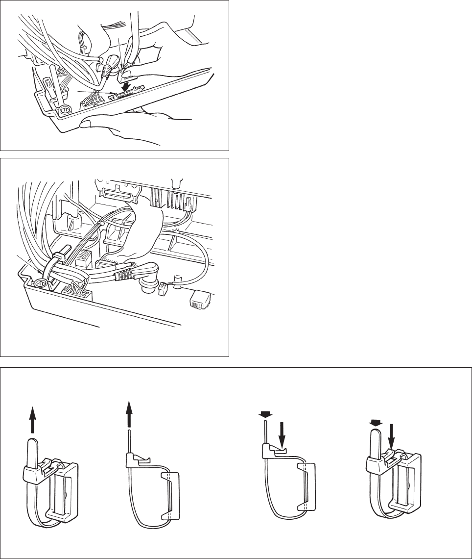
[ Connection of the connector for CP panel ]
Exclusive connectors are prepared for connection of
the connector for CP-160.
Paying attention to the orientation of the connector
!2, connect it to connector !3 located on the circuit
board. After connecting, securely lock the connector.
9) After inserting the connector, put all cords together
with cable clip band !4 located on the side of the
box.
(Caution)
1. Fix the cord clamp and the cable clip band
following the attaching procedure.
2. When removing the cable clip band,
remove it while pressing the hook of the
cable clip band.
(Caution) 1. Fix the cable clip band following the attaching procedure as shown in the figure.
2. To remove the cable clip band, push the cable clip band until it comes off while pressing
the hook of the band following the removing procedure as shown in the figure.
How to fix cable clip band !4
Pull
How to remove cable clip band !4
Push
Pushing the hook portion, push the band to remove it.
Push the hook.
Pull Push
!2
!3
!4
Push
− 7 −
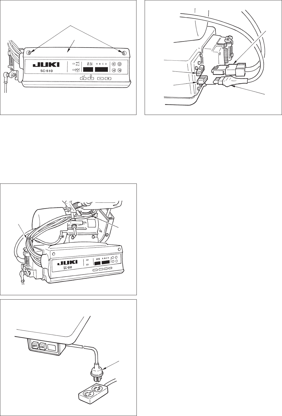
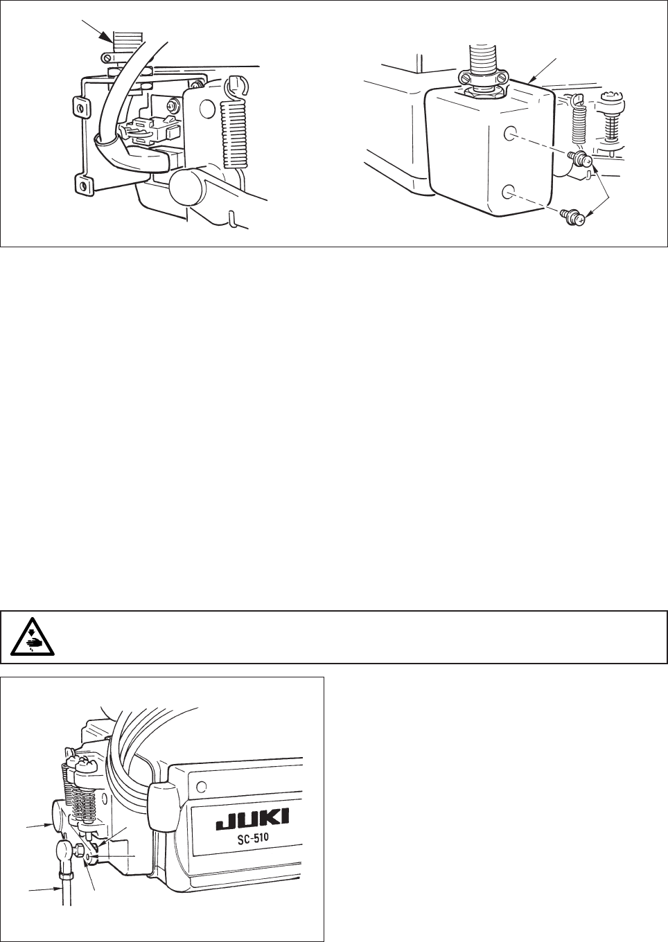
12)Connect connector 4P !5 to connector !
6 locat
ed
on the side of the box.
13)Connect motor
outpu
t cord !7 of the power switch
to connector !8.
14)Binding of the cords coming from machine head
Bind the cable attached to the machine head at
two places with the cable clip band !9 supplied with
the unit as accessories as shown in the figure.
(Do not bind the motor signal cable together.)
15)Make sure that the power switch is turned OFF
and insert power supply cord @0 coming from the
power switch into the power plug socket.
(Caution)
1. Check again the supply voltage indicated
on the control box before connecting the
power cord.
2. Prepare the power switch conformed to the
safety standard.
3. Be sure to connect the ground wire ( green
/ yellow).
!5
!6
!7
!8
@0
10) Close front cover 4 while paying attention to
pinching of the wire.
11) After that, fix it with the screw 5.
5
4
!9
!9
− 8 −
1
2
3
4
Crimp style terminal section
b
4
5
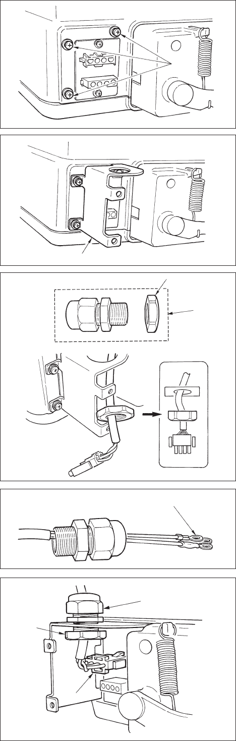
[ For CE specifications only ]
1) Remove three screws 1 located on the side of the
control box.
2) Set power source cover installing plate 2 supplied
with the unit as accessories to the control box main
unit with the three screws which have been
removed.
3) Remove nut section 4 from cord bush 3 supplied
with the unit as accessories.
4) After checking the direction of the nut, pass the
nut through the power source cord supplied with
the unit as accessories.
(Caution) Note that the flat face of the nut should
face the power source cover installing plate
side.
5) Pass the terminal of the power source cord through
the hole from the inside of the power source cover
installing plate.
6) Pass the cord bush, while paying attention to the
direction, through the power source cord from the
power source cord terminal side.
7) Insert connector 5 of the power source cord to
the connector (top) of the control box.
(Caution) Securely insert the connector while
paying attention to the direction.
8) Tighten nut 4 and securely fix the cord bush to
the installing plate.
9) Clamp section b of the cord bush and securely fix
it to the cord.
− 9 −
6
8
7
10) Insert connector 6 coming from the motor to the
connector of the control box from the inside.
11) Securely fix power source cover 7 supplied with
the unit as accessories to power source cover
installing plate 2 with two screws 8 supplied with
the unit as accessories while being careful that the
cord is not caught by the cover.
* For handling the cable, refer to 14) and 15) of “6. Connecting the cords”.
1
2
3
1) Remove three screws 1 located on the side of the
control box.
2) Set power source cover installing plate 2 supplied
with the unit as accessories to the control box main
unit with the three screws which have been
removed.
3) Pass the terminal of the power source cord through
the hole from the inside of the power source cover
installing plate.
4) After checking the direction of the nut 3, pass the
nut through the power source cord supplied with
the unit as accessories and insert it into the conduit.
(Caution) Note that the flat face of the nut should
face the power source cover installing plate
side.
5) Securely fix it to the installing fittings with nut 3
from both sides.
[ For LA specifications only ]
− 10 −
7. Attaching the connecting rod
1) Fix connecting rod 1 to installing hole B of pedal
lever 2 with nut 3.
2) Installing connecting rod 1 to installing hole A will
lengthen the pedal depressing stroke, and the pedal
operation at a medium speed will be easier.
WARNING :
To protect against possible personal injury due to abrupt start of the machine, be sure to start the
following work after turning the power off and a lapse of 5 minutes or more.
5
6
6) Insert connector 4 of the power source cord to the connector (top) of the control box.
(Caution) Securely insert the connector while paying attention to the direction.
7) Securely fix power source cover 5 supplied with the unit as accessories to power source cover installing
plate 2 with two screws 6 supplied with the unit as accessories while being careful that the cord is not
caught by the cover.
* For handling the cable, refer to 14) and 15) of “6. Connecting the cords”.
4
1
2
B
A
3
− 11 −
2
6) When operation panel 7 is connected, various
sewing patterns such as reverse feed stitching at
sewing start, reverse feed stitching at sewing end,
etc. can be set.
Refer to the Instruction Manual for the operation
panel for the details.
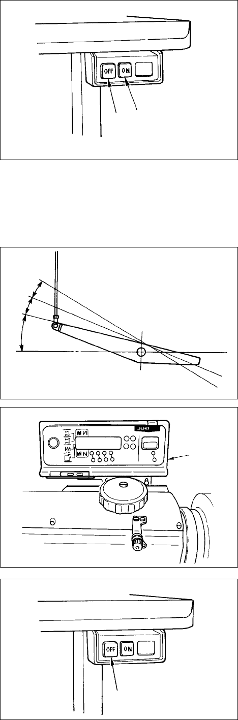
7) When sewing is completed, make sure that the
sewing machine has stopped.
Then, press the OFF button 2 of the power switch
to turn OFF the power.
3) When depressing front part 4 of the pedal, the
sewing machine rotates at the number of
revolutions in accordance with the depressing
amount.
When the pedal is returned to the neutral position,
the sewing machine stops.
4) When lightly depressing back part 5 of the pedal,
the presser goes up. (PFL type only)
5) When strongly dpressing back part 6 of the pedal,
thread trimming is performed.
5
4
6
#. FOR THE OPERATOR
1. Operation of SC-510
1) Press ON button 笊 of the power switch to turn ON
the power.
(Caution) When the buzzer is kept beeping
immediately after turning ON the power,
press OFF button 2 on the sewing machine
to turn OFF the power since connection of
the cord or power voltage may be wrong.
2) When the needle bar is not in its UP position, it
automatically rotates to reach the UP position.
(Caution)
1. When turning ON the power for the first
time, it will be slightly delayed since
initialization is performed.
2. When turning ON the power, do not place
your hands under the needle.
笊
笆
7
− 12 −
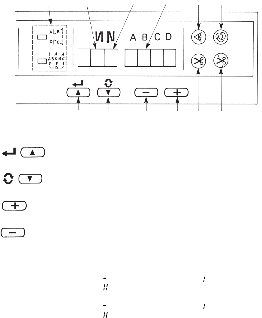
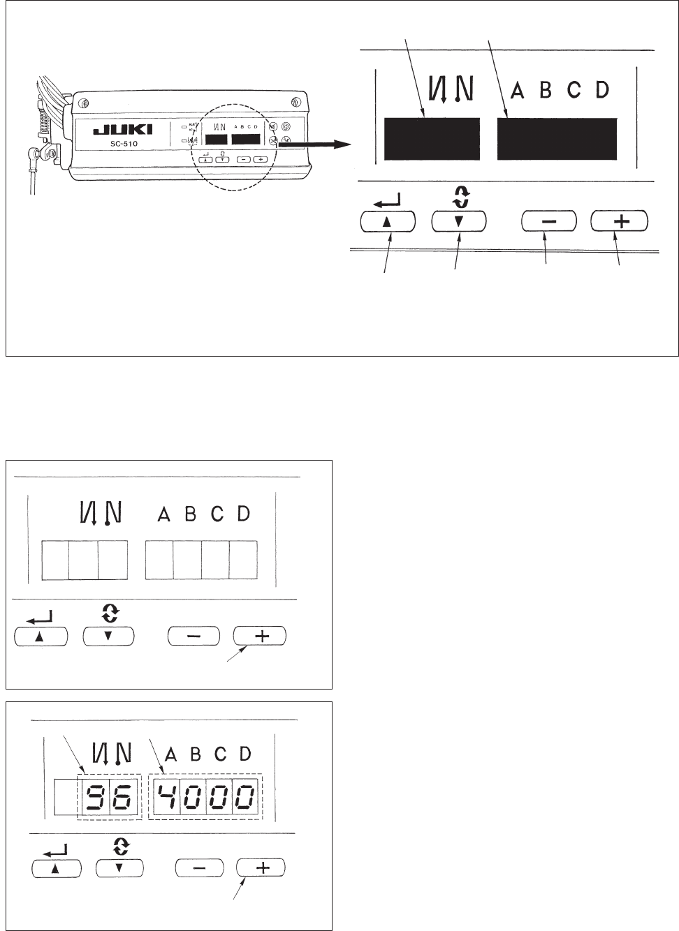
2. Explanation of the operation panel
1 / switch : Used for determining the contents of setting.
When this switch is pressed, flashing stops and the contents of setting
are determined.
2 / switch : Used for changing the contents of setting.
When this switch is pressed, changeable positions flash on and off.
By pressing the switch, flashing position shifts in the right direction.
3 switch : Used for changing the contents of the selected display (flashing
section).When this switch is pressed, the contents of the display
increase.
4 switch : Used for changing the contents of the selected display (flashing
section).
When this switch is pressed, the contents of the display decrease.
5PATTERN SELECTION display : The selected pattern is displayed.
6REVERSE STITCHING : Rendered effective when reverse stitching pattern is selected.
AT START display “ ” Without reverse stitching display / “ ” Reverse stitching display/
“ ” Double reverse stitching display
7REVERSE STITCHING : Rendered effective when reverse stitching pattern is selected.
AT END display “ ” Without reverse stitching display / “ ” Reverse stitching display/
“ ” Double reverse stitching display
8NUMBER OF STITCHES display : Number of stitches of reverse stitching or overlapped stitching is
displayed.
9MATERIAL EDGE SENSOR : Lights up when the material edge sensor setting is selected.
display Function setting No. 2
!0 ONE-SHOT AUTOMATIC : Lights up when the one-shot automatic stitching is selected.
STITCHING display Function setting No. 76
!1 AUTOMATIC : Lights up when the automatic thread trimming by depressing the
THREAD TRIMMING display front part of the pedal is selected.
Function setting No. 3
!2 THREAD TRIMMING : Lights up when the thread trimming prohibition is selected.
PROHIBITION display Function setting No. 9
1243!1 !2
6789!0
5
− 13 −
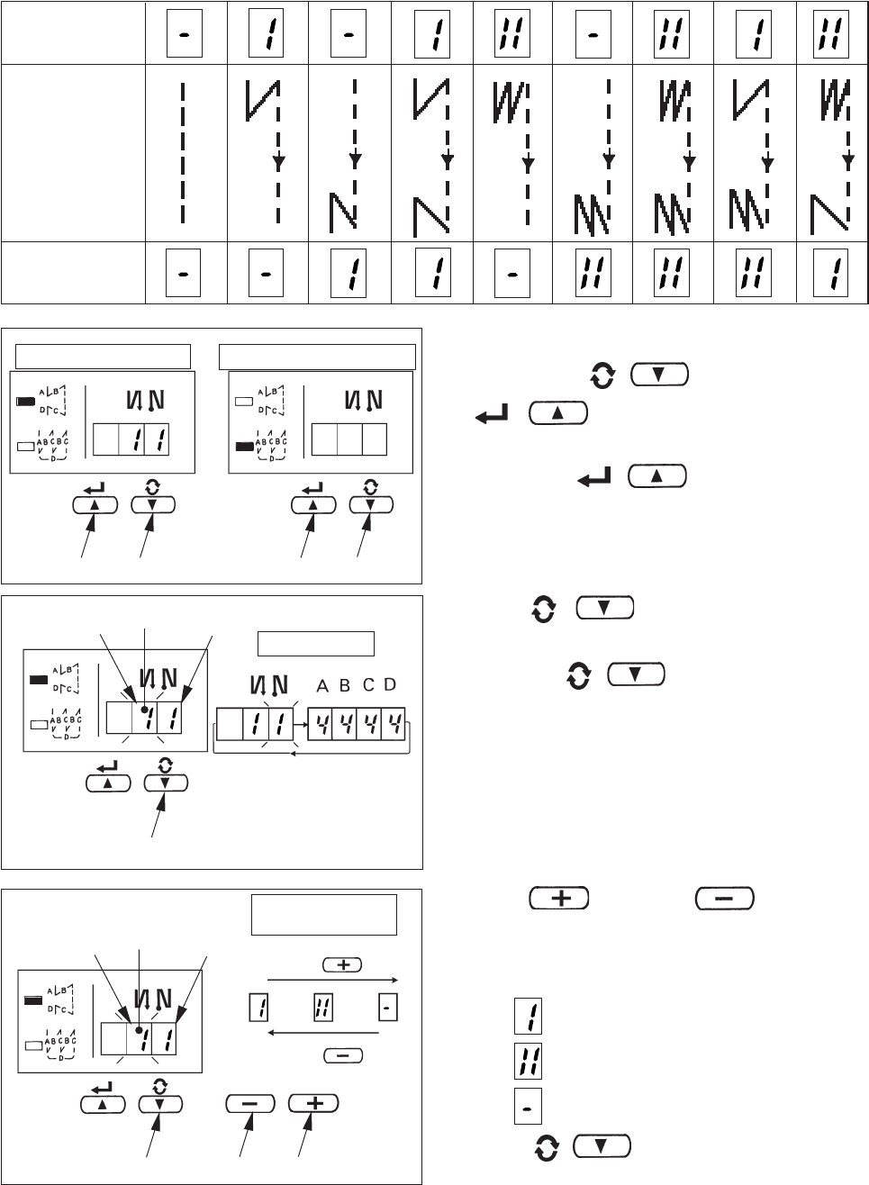
3) Press switch 3 or switch 4 and
select the reverse stitching pattern.
Reverse stitching patterns and displays are as
follows.
: Reverse stitching
: Double reverse stitching
: Without reverse stitching
4) Press / switch 1 to make reverse
stitching at end display 7 flash on and off, and set
the pattern in the same way as step 3).
[ Setting procedure of the reverse stitching ]
1) Hold pressing / switch 1, and press
/ switch 2 to select the reverse
stitching pattern.
(Every time / switch 2 is pressed,
reverse stitching pattern/overlapped stitching
pattern change over alternately.)
2) Press / switch 1 to make reverse
stitching at start display 6 flash on and off.
Every time / switch 1 is pressed, the
flashing position shifts in the right direction.
(Caution) The sewing machine does not start in
the flashing state.
Operating procedure of the sewing pattern
(1) Reverse stitching pattern
Reverse stitching patterns below can be set by using the operation panel.
Reverse stitching patterns that can be set
Reverse stitching
at start display
Sewing pattern
A
Overlapped stitching pattern
Reverse stitching pattern
B
D
C
D
C
A
B
A
BB
A
D
C
D
C
A
B
A
B
A
B
D
C
D
C
D
C
D
C
D
C
A
B
A
B
1
21
2
1
Shift direction
Flash
Contents of reverse
stitching slection
updating with swith3
3
4
⇔
7
6
7
6Flash
updating with swith4
1
Reverse stitching
at end display
− 14 −
5) Press / switch 1 to make number of
stitches display 8 flash on and off, and set the
number of stitches for the respective processes of
the stitching.
6) Press switch 3 or switch 4 to
change the number of stitches.
The number of stitches can be changed up to as
many as 15 stitches for the A, B, C, and D
processes respectively.
However, displays are as follows.
10 stitches = A, 11 stitches = b, 12 stitches = c, 13
stitches = d, 14 stitches =E and 15 stitches = F
7) When the setting of all items has been completed,
press / switch 2 to determine the
contents of the setting. (Flashing stops.)
A
B
C
B
C
D
1
21
2
⇔
1
243
Overlapped stitching pattern
Reverse stitching pattern
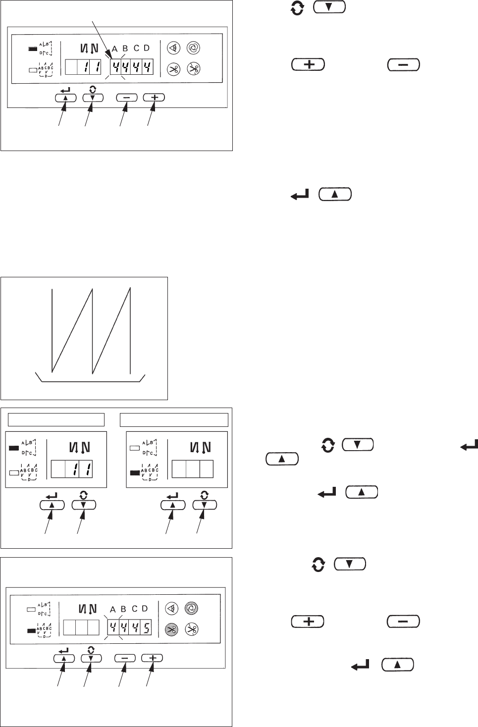
(2) Overlapped stitching pattern
Overlapped stitching patterns below can be set by using the operation panel.
A : Number of stitches of normal stitching setting
0 to 15 stitches
B : Number of stitches of reverse stitching setting
0 to 15 stitches
C : Number of stitches of normal stitching setting
0 to 15 stitches
D : Number of times of repetition
0 to 9 times
(Caution) When process D is set to 5 times, the
sewing is repeated as A / B / C / B / C.
[Setting procedure of the overlapped stitching]
1) Hold pressing / switch1, and press
/ switch 2 to select the overlapped stitching
pattern.
(Every time / switch 2 is pressed,
reverse stitching pattern/overlapped stitching
pattern change over alternately.)
2) The number of stitches for process A becomes in
flashing state.
3) Every time / switch 1 is pressed, the
flashing position shifts in the right direction and the
display of the process where setting can be
changed flashes on and off.
4) Press switch 3 or switch 4 to
change the number of stitches.
5) When the setting of all processes has been
completed, press / switch 2 to
determine the contents of the setting. (Flashing
stops.)
(Caution) When the overlapped stitching is
selected, the automatic operation display
flashes on and off. It is not possible to
release the automatic operation.
1
243
8
− 15 −
a
a
13
4
13
4
(3) Special setting
For material end sensor function, automatic thread trimming function, one-shot automatic stitching function and thread
trimming prohibition function which are displayed in the front panel, it is possible to change the set value by directly
moving to the function setting mode while the power is turned ON in addition to the normal function setting procedure.
[ Moving procedure to the function setting mode ]
1) Hold pressing / switch 1, and press
switch 3 to move to the function setting
mode.
(Caution) Function setting No. 2 is displayed
immediately after the changeover.
2) When returning to the normal mode, press /
switch 2 and determine the contents of
the setting.
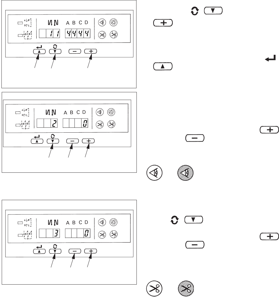
1Material end sensor function setting (Function
setting No. 2)
It is rendered effective when connecting the
optional material end sensor.
It is possible to change the set value with
switch 3 or switch 4
0 : Material end sensor function is prohibited.
1 : Material end sensor function is effective.
When "1" is selected, material
end sensor display lights up
when the mode has returned to
the normal one.
2Thread trimming operation after material end stop
setting (Function setting No. 3)
Press / switch 1 to advance to the
function setting No. 3.
It is possible to change the set value with
switch 3 or switch 4.
0 : Material end stop
1 : Automatic thread trimming after detection
of material end
When "1" is selected, the
automatic thread trimming
display lights up when the mode
is returned to the normal one.
13
2
− 16 −
a
a
13
4
13
4
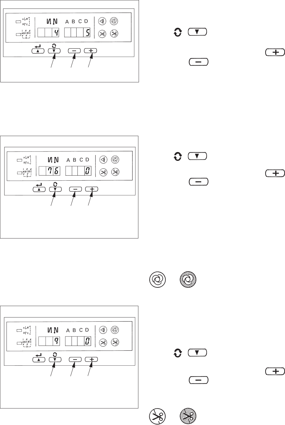
4One-shot automatic stitching setting function
(Function setting No. 76)
Press / switch 1 to advance to the
function setting No. 76.
It is possible to change the set value with
switch 3 or switch 4.
0 : Pedal designated speed is prior.
1 : Automatic operation
(Caution) It is rendered effective when the material
end sensor function is set.
It is not possible to prohibit the one-shot
operation at the time of the overlapped
stitching operation.
Speed of rotation is the speed set at the
function setting No. 38.
When "1" is selected, the one-
shot automatic stitching display
lights up when the mode is
returned to the normal one.
5Thread trimming prohibition function setting
(Function setting No. 9)
Thread trimming operation at normal stitching and
overlapped stitching can be prohibited by selecting
the thread trimming prohibition.
Press / switch 1 to advance to the
function setting No. 9.
It is possible to change the set value with
switch 3 or switch 4.
0 : Thread trimming is effective.
1 : Thread trimming is prohibited.
When "1" is selected, the thread
trimming prohibition display lights
up when the mode is returned to
the normal one.
3Number of stitches to stop the sewing machine after
detection of material end setting (Function setting
No. 4)
Press / switch 1 to advance to the
function setting No. 4.
It is possible to change the set value with
switch 3 or switch 4.
Specified number of stitches : 0 to 19 stitches
(Caution) When the specified number of stitches
is insufficient, there is a case where the
sewing machine cannot stop within the
specified number of stitches depending on
the speed of rotation of the sewing
machine.
13
4
− 17 −
3. Setting for functions of SC-510
Functions can be selected and specified by means of the four setting switches and light emitting diode located
inside the front cover of the SC-510.
(Caution) • Do not perform switch operations other than those described in the following explanations.
•Be sure to re-turn the power switch ON after one second or more has passed. If the power
is turned ON immediately after turning it OFF, the sewing machine may not work normally.
In this case, turn ON the power again.
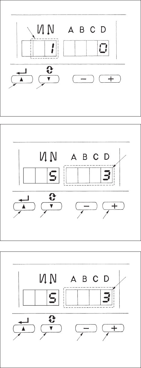
How to change over to the function setting modo
1) Turn OFF the power to the unit.
2) Pressing switch 4, turn ON the power to the unit.
3) Indication 5, 6 will be shown on the display. (If
the indication fails to change, re-perform the
procedures 1) and 2).
1234
5
6
4
4
1Switch for entering specified value changed
and updating setting No. in DOWN direction
2Switch for entering specified value changed
and updating setting No. in UP direction
Specified value
Specified No.
3Down switch (DOWN)
4Up switch (UP)
− 18 −
4) When you want to advance the setting No., press
switch 2 to advance the setting No.
When you want to return the setting No., press
switch 1 to return the setting No.
(Caution) When switch 1 (switch 2) is held
pressing, the setting No. will return (will
advance) continuously. When the setting
No. is advanced (returned), the contents
which are before by one (after by one) will
be determined. So, be careful when
changing the contents (up/down switch is
touched).
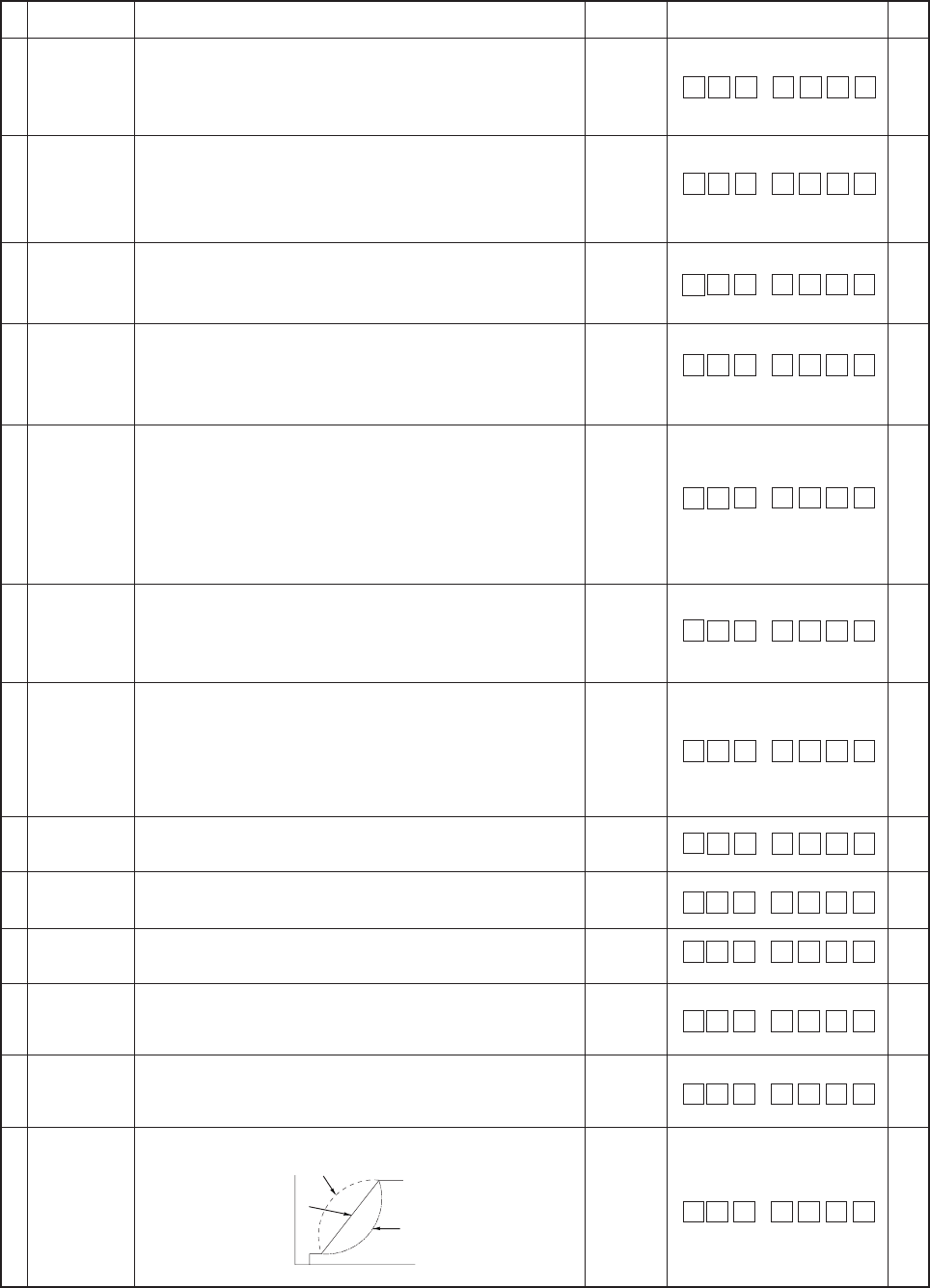
EXAMPLE) CHANGING THE FLICKER
REDUCING FUNCTION (SETTING No. 5)
Press switch 2 five times to set the setting No. to
“5”.
Existing set value is displayed in LED 5. (Standard
is "0".) Press switch 4 three times to change to “3”.
(Caution) Keep pressing switch 4 or switch 3,
and the setting vaue can be changed
continuously.
5) When the change has been completed, press
switch 1 or 2 to specify the changed value.
(Caution)
1. When turning OFF the power before
performing this work, the contents which
have been changed are not updated.
2. Press switch 1, and screen display will
change to the contents of the setting No.
which is before by one.
3. Press switch 2, and screen display will
change to the contents of next setting No.
After completing the operation, turn OFF
the power and turn ON the power again to
return to the normal operation.
After completing the operation, turn OFF the power
and turn ON the power again to return to the normal
2
1
Specified
No.
2
14
3
5
2
14
3
5

− 19 −
*Do not change the set values with asterisk (*) mark as they are functions for maintenance. If the standard set value set at the
time of delivery is changed, it is in danger of causing the machine to be broken or the performance to be deteriorated.
If it is necessary to change the set value, please purchase the Engineer’s Manual and follow the instructions.
(Descriptions of setting in this list are the standard values at the time of delivery.)
However, contents of function setting are subject to change for improvement of function and performance without notice.
4. Function setting list
Indication of
function setting
Item
Soft start
function
Material end
sensor function
Thread trimming
function by
material end
sensor
Number of
stitches for
material end
sensor
Flicker
reducing
function
Bobbin thread
counting
function
Unit of bobbin
thread
counting down
Number of
rotation of
reverse feed
stitching
Thread
trimming
prohibiting
function
Setting of
needle bar
stop position
when the
sewing
machine stops.
Click sound of
key switch
mounted on
PSC
Optional input/
output setting
Function of
prohibiting start
of the sewing
machine by
bobbin thread
counter
Sewing
counter
Function of
neutral presser
lifting
No.
1
2
3
4
5
6
7
8
9
10
11
12
13
14
21
0 to 9
(Stitches)
0/1
0/1
0 to 19
(Stitches)
0 to 3
0/1
0 to 2
150 to 3,000
(r.p.m.)
0/1
0/1
0/1
0 to 2
0/1
0/1
Description
The number of stitches to be sewn at a low speed when the soft-
start function is used at the start of sewing.
0 : Soft-start function is not operative.
Material end sensor function (used in case of without panel).
0 : Material end detection function is not operative.
1 : After detecting material end, the specified number of stitches
(No. 4) will be sewn, and the sewing machine will stop.
Thread trimming function by material end sensor (used in case of
without panel).
0 : Automatic thread trimming function after detection of material
end is not operative.
1 : After detecting material end, the specified number of stitches
(No. 4) will be sewn, and the sewing machine will stop and
perform automatic thread trimming.
Number of stitches for material end sensor (used in case of without
panel).
Number of stitches from detection of material end to stop of the
sewing machine.
Flicker reducing function (If the hand lamp flickers).
0 : Flicker reducing function is not operative.
1 : Less effective / 3 : Highly effective
Bobbin thread counting function
0 : Bobbin thread counting function is not operative.
1 : Bobbin thread counting function is operative.
Unit of bobbin thread counting down
10 : Count/10 stitches
15 : Count/15 stitches
20 : Count/20 stitches
Sewing speed of reverse feed stitching
Thread trimming prohibiting function (used in case of without panel).
0 : Thread trimming prohibiting function is not operative.
1 : Thread trimming is prohibited.
(Output of solenoid is prohibited. : Thread trimmer and wiper)
Position of needle bar is specified when the sewing machine stops.
0 : Predetermined lowest position
1 : Predetermined highest position
Click sound of key switch mounted on PSC is specified.
0 : Click is not operative.
1 : Click is operative.
Changeover of optional switch.
Function of prohibiting start of the sewing machine by bobbin thread
counting
0 : When counting is out (-1 or less) Function of prohibiting start
of the sewing machine is not operative.
1 : When counting is out (-1 or less) Function of prohibiting start
of the sewing machine after thread trimming is operative.
2 : When counting is out (-1 or less), the sewing machine stops
once. Function of prohibiting start of the sewing machine after
thread trimming is operative.
Counting function of sewing (number of completion of process)
0 : Sewing counter function is not operative.
1 : Sewing counter function is operative.
Function of lifting presser foot when the pedal is in neutral position.
0 : Function of neutral automatic presser lifting is not operative.
1 : Selection of function of neutral presser lifting.
*
Ref.
page
23
23
23
23
23
23
23
23
23
24
27
27
27
27
10
20
90
10 0
11 1
12 0
22
25
Function of
changeover of
compensating
switch on the
operation
panel function
Thread
trimming
motion
condition
Function of needle up/down compensating switch on the operation
panel can be changed.
0 : Needle up/down compensation
1 : One stitch compensation
This function sets the thread trimming motion after DOWN position
has been off by turning handwheel by hand.
0 : Thread trimming after turning handwheel by hand is permitted.
1 : Thread trimming after turning handwheel by hand is prohibited.
0/1
0/1
30
45
50
61
70
25 1
22 0
21 0
14 1
13 0
81900
Setting
range

− 20 −
38
39
40
41
42
43
44
45
47
48
51
One-shot
speed
Pedal stroke at
the start of
rotation
Low speed
section of
pedal
Starting
position of
lifting presser
foot by pedal
Starting
position of
lowering
presser foot
Pedal stroke 2
for starting
thread trimming
Pedal stroke for
reaching the
maximum
number of
rotation
Compensation of
neutral point of
the pedal
Holding time of
lifting auto-lifter
Pedal stroke 1
for starting
thread trimming
Compensation of
solenoid-on
timing of reverse
feed stitching at
the start of
sewing
One-shot speed (The max. value depends on the number of rotation
of the sewing machine head.)
Position where the sewing machine starts rotating from pedal neutral
position (Pedal stroke)
Position where the sewing machine starts accelerating from pedal
neutral position (Pedal stroke)
Position where the cloth presser starts lifting from pedal neutral
position (Pedal stroke)
Starting position of lowering presser foot
Stroke from the neutral position
Position 2 where the thread trimming starts from pedal neutral position
(When the function of lifting presser foot by pedal is provided.) (Pedal
stroke)
Position where the sewing machin reaches its highest sewing speed
from pedal neutral position (Pedal stroke)
Compensation value of the pedal sensor
Limitation time of waiting for lifting solenoid type auto-lifter device
Position where thread trimming starts from pedal neutral position
(Standard pedal) (Pedal stroke)
Compensation of starting the solenoid for reverse feed stitching when
reverse feed stitching at the start of sewing is performed.
150 to MAX
(r.p.m.)
10 to 50
(0.1 mm)
10 to 100
(0.1 mm)
–60 to –10
(0.1mm)
8 to 50
(0.1 mm)
–60 to –10
(0.1 mm)
10 to 150
(0.1 mm)
–15 to 15
10 to 600
(second)
–60 to –10
(0.1 mm)
–36 to 36
(10˚)
*
Item
No. Setting
range
Description Ref.
page
27
28
28
28
28
23
29
29
29
*
Indication of
function setting
*
*
*
*
*
Suction time of
the first start of
the back
solenoid
Function of
reverse feed
stitching on the
way
Number of
stitches of
reverse feed
stitching on the
way
Effective
condition of
reverse feed
stitching on the
way when the
sewing machine
is stopping.
Thread trimming
function by
reverse feed
stitching on the
way
Number of
rotation at a low
speed
Number of
rotation of soft-
start
29
30
31
32
33
35
37
This function sets the suction motion time of the back-tack solenoid.
50 ms to 500 ms
Function of reverse feed stitching on the way
0 : Function of reverse stitching on the way is not operative.
1 : Function of reverse feed stitching on the way is operative.
Number of stitches of reverse feed stitching on the way.
Effective condition of reverse feed stitching on the way
0 : Function is not operative when the sewing machine stops.
1 : Function is operative when the sewing machine stops.
Thread trimming function by reverse feed stitching on the way
0 : Automatic thread trimming function after completion of reverse
feed stitching on the way is not operative.
1 : Automatic thread trimming after completion of reverse feed
stitching on the way is performed.
Lowest speed by pedal
Sewing speed at the start of sewing (soft-start)(The max. value
depends on the number of rotation of the sewing machine head.)
50 to 500
(ms)
0/1
0 to 19
(Stitches)
0/1
0/1
150 to 250
(r.p.m.)
100 to MAX
(r.p.m.)
29 250
51 10
48 -35
47 60
45 0
44 150
43 –51
42 10
41 –21
40 60
39 30
38 2500
37 800
35 200
33 0
32 0
31 4
30 0
*
*
*Do not change the set values with asterisk (*) mark as they are functions for maintenance. If the standard set value set at the
time of delivery is changed, it is in danger of causing the machine to be broken or the performance to be deteriorated.
If it is necessary to change the set value, please purchase the Engineer’s Manual and follow the instructions.
(Descriptions of setting in this list are the standard values at the time of delivery.)
However, contents of function setting are subject to change for improvement of function and performance without notice.
− 21 −
*
29
29
30
30
30
30
30
31
31
31
*
No.
Item
Description Setting
range
Ref.
page
52
53
55
56
Compensation of
solenoid-off
timing of reverse
feed stitching at
the start of
sewing
Compensation of
solenoid-off
timing of reverse
feed stitching at
the end of
sewing
Foot lift after
thread trimming
Compensation of releasing the solenoid for reverse feed stitching
when reverse feed stitching at the start of sewing is performed.
Compensation of releasing the solenoid for reverse feed stitching
when reverse feed stitching at the end of sewing is performed.
Function of lifting presser foot at the time of (after) thread trimming
0 : Not provided with the function of lifting presser foot after thread
trimming
1 : Provided with the function of lifting presser foot automatically
after thread trimming
Function of reverse revolution to lift the needle at the time of (after)
thread trimming
0 : Not provided with the function of reverse revolution to lift the
needle after thread trimming
1 : Provided with the function of reverse revolution to lift the needle
after thread trimming
–36 to 36
(10˚)
–36 to 36
(10˚)
0/1
0/1
58
59
60
64
73
75
76
Bobbin thread
remaining
amount detection
function
Function of
holding
predetermined
upper/lower
position of the
needle bar
Function of Auto/
Manual change-
over of reverse
feed stitching at
the start of
sewing
Function of stop
immediately after
reverse feed
stitching at the
start of sewing
Change-over
speed of EBT
(end back tack)
Retry function
Rotating
direction of motor
One-shot
function up to
end of material
Function of holding predetermined upper/lower position of the needle
bar
0 :Not provided with the function of holding predetermined upper/
lower position of the needle bar
1 : Provided with the function of holding predetermined upper/
lower position of the needle bar (holding force is weak.)
2 : Provided with the function of holding predetermined upper/
lower position of the needle bar (holding force is medium.)
3 : Provided with the function of holding predetermined upper/
lower position of the needle bar (holding force is strong.)
This function can specify the sewing speed of reverse feed stitching
at the start of sewing.
0 : The speed will depend on the manual operation by pedal, etc.
1 : The speed will depend on the specified reverse feed stitching
speed (No. 8).
Function at the time of completion of reverse feed stitching at the
start of sewing
0 : Not provided with the function of temporary stop of the sewing
machine at the time of completion of reverse feed stitching at
the start of sewing
1 : Provided with the function of temporary stop of the sewing
machine at the time of completion of reverse feed stitching at
the start of sewing.
Initial speed when starting reverse feed stitching at the sewing end
This function is used when needle cannot pierce materials .
0 : Normal
1 : Retry function is provided.
Normal rotating direction of motor
0 : Clockwise
1 : Counterclockwise
One-shot automatic stitching up to end of material is performed. (Used
in case of without panel)
0 : Without one-shot function
1 : With one-shot function
0 to 3
0/1
0/1
Indication of
function setting
84
87
Presser lifter
solenoid initial
motion suction
time
Function of
pedal curve
selection
Suction motion time of presser lifter solenoid
50 to 500 ms
Pedal curve is selected. (Improving pedal inching operation)
0
2
1
Number of rotations
Pedal stroke
0 to 250
(r.p.m.)
0/1
0/1
0/1
50 to 500
(ms)
0/1/2
53 18
52 16
55 1
56 0
58 0
59 1
60 0
64 180
73 1
75 1
76 0
84 250
87 0
*Do not change the set values with asterisk (*) mark as they are functions for maintenance. If the standard set value set at the
time of delivery is changed, it is in danger of causing the machine to be broken or the performance to be deteriorated.
If it is necessary to change the set value, please purchase the Engineer’s Manual and follow the instructions.
(Descriptions of setting in this list are the standard values at the time of delivery.)
However, contents of function setting are subject to change for improvement of function and performance without notice.

− 22 −
*
31
31
31
No.
Item
Description Setting
range
Ref.
page
Indication of
function setting
*
89
91
92
93
96
It is effective in combination with the machine head provided with
tension release function.
0 : Tension release function is ineffective.
1 : Tension release function is effective.
Function of compensating stitching when turning handwheel by hand
at the time of completion of constant-dimension stitching
0 : Function of compensating stitching is effective.
1 : Function of compensating stitching is prohibited.
Function to reduce speed at the time of completion of reverse feed
stitching at the start of sewing.
0 : Speed is not reduced.
1 : Speed is reduced.
Operation of needle up/down compensating switch is changed after
turning ON the power or thread trimming.
0 : Normal (needle up/down compensating stitching only)
1 : One stitch compensating stitching is performed only when
aforementioned changeover is made. (Upper stop / upper
stop)
Max. number of rotation of the sewing machine head can be set.
* Setting varies in accordance with resistance pack to be connected.
Tension
release
function
Function of
prohibiting
compensation
operation after
turning
handwheel by
hand
Function of
reducing speed
of reverse feed
stitching at the
start of sewing
Function added
to needle up/
down
compensating
switch
Max. number of
rotation setting
0/1
0/1
0/1
0/1
150 to MAX
(rpm)
89 0
96 4000
93 0
92 0
91 1
*Do not change the set values with asterisk (*) mark as they are functions for maintenance. If the standard set value set at the
time of delivery is changed, it is in danger of causing the machine to be broken or the performance to be deteriorated.
If it is necessary to change the set value, please purchase the Engineer’s Manual and follow the instructions.
(Descriptions of setting in this list are the standard values at the time of delivery.)
However, contents of function setting are subject to change for improvement of function and performance without notice.
− 23 −
5. Detailed explanation of selection of functions
1Selection of the soft-start function (Function setting No. 1)
The needle thread may fail to interlace with the bobbin thread at the start of sewing when the stitching pitch
(stitch length) is small or a thick needle is used. To solve such problem, this function (called “soft-start”) is
used to limit the sewing speed, thereby assuring successful formation of the starting stitches.
0 : The function is not selected.
1 to 9 : The number of stitches to be sewn under the soft-start mode.
The sewing speed limited by the soft-start function can be changed. (Function setting No. 37)
Data setting range
100 to MAX rpm <50 rpm>
2Material end sensor (ED : optional) function (Function setting No. 2 to 4)
This function is possible when the material end sensor (ED) is attached.
As for the details, refer to the instruction manual for the material end sensor.
(Caution) Setting will be invalid when the material end sensor is not attached, or CP-160 is connected.
3Flicker reducing function (Function setting No. 5)
The function reduces flickering of the hand lamp at the start of sewing. The higher the set value increases, the
more effective the function will work.
Setting range
0 to 3
0 : Flicker reducing function does not work. to 3 : Flickering is effectively reduced.
(Caution) The more effective the flicker reducing function works (the more the set value is made),
the lower the start-up speed of the sewing machine will become.
4Bobbin thread counting function (Function setting No. 6)
When the control panel (CP-160) is used, the function subtracts from the predetermined value and indicates
the used amount of bobbin thread.
For the details, refer to the instruction manual for the control panel.
(Caution) If “0” is set, the LCD indication on the control panel will go out and the bobbin thread
counting function will be invalid.
5Thread trimming prohibiting function (Function setting No. 9)
This function turns OFF thread trimming solenoid output and wiper solenoid output when thread trimming is
actuated. [If the control panel (CP-160) is used with the sewing machine, this function will work in accordance
with the function setting on the control panel.]
By this function, separate sewing material can be spliced and sewn without trimming thread.
0 : off Thread trimming is operative. (thread can be trimmed).
1 : on Thread trimming is inoperative. (thread can not be trimmed).
6Setting of the needle bar stop position when the sewing machine stops (Function setting No. 10)
The position of the needle bar when the pedal is in its neutral position is specified.
0 : Down The needle bar stops in the lowest position of its stroke.
1 : Up The needle bar stops in the highest position of its stroke.
(Caution) If the stop position of the needle bar is set to the highest position, the thread trimming
action will be taken after the needle bar comes down once to the lowest position.
10
37 800
50
7Sound of click of the key switch mounted on the PSC box (Function setting No. 11)
This function selects whether the sound is effective or ineffective when operating the four key switches mounted
on the PSC box.
0 : off The sound of click is ineffective.
1 : on The sound of click is effective.
90
10 0
11
− 24 −
8 Selection of the optional input/output function (Function setting No. 12)
12 OPT _
900 _End
in__
ouT_
***901
908
***911
918
12 OPT _
900 in__
noP901
TSW901
[\
L4
L4901
H4
[\
noP902
900 in
End
1243
Select function setting No. 12 with the operating procedure of function setting
procedures 1) through 4).
Select the items of "End", "in" and "ouT" with keys 3 and 4.
[When "in" is selected]
The port Nos. are displayed in the left 3 digits. Designate the input port with
key 1 or 2. Designate the function of input port with key 3 or 4.
The function code and the abbreviation are alternately displayed in the 4-digit
LED.(For the relation between signal input No. and connector pin array, refer
to the separate list.)
[When "ouT" is selected]
The port Nos. are displayed in the left 3 digits. Designate the output port with
key 1 or 2. Designate the function of output port with key 3 or 4.
The function code and the abbreviation are alternately displayed in the 4-digit
LED. (For the relation between signal input No. and connector pin array, refer
to the separate list.)
(Caution) Note that the voltage used in output function should not exceed the voltage set with W1
and W2. (For the details, refer to Engineer's Manual.)
* Example) Setting the thread trimming function to the optional input port 1
1. Select function setting No. 12 with the operating procedure of function setting
procedures 1) through 4).
2. Select the item of "in" with keys 3 and 4.
3. Select the port of 901 with key 2.
4. Select the thread trimming function, "TSW" with keys 3 and 4.
5. Determine the thread trimming function, "TSW" with key 2.
6. Set ACTIVE of the signal with keys 3 and 4.
Set the display to "L" when the signal is "Low" and performing thread
trimming, and set the display to "H" when the signal is "High" and performing
thread trimming.
7. Determine the aforementioned function with key 2.
8. Finish the optional input with key 2.
9. Select the item of "End" with keys 3 and 4 to return to the function setting
mode.
* For the other optional function, it is possible to program simple input/output sequence control.
(For the details, refer to Engineer's Manual.)
Operation keys array
Optional input
1 to 8 are
displayed.
Optional output
1 to 8 are
displayed.
Lighting alternately
<? ・・・
<?

− 25 −
Input function list
0
1
2
3
4
5
6
7
8
9
10
11
12
13
14
15
16
17
18
19
20
Abbreviation
This function works as the input signal of material edge sensor.
Rotation by pedal is prohibited.
Output of thread trimming is prohibited.
This function works as low speed switch for standing sewing machine.
This function works as high speed switch for standing sewing machine.
UP stop motion is performed when switch is pressed during
DOWN stop.
Brake stop motion by reverse revolution is performed at specified
angle when switch is pressed during DOWN stop
Rotation is prohibited.
This function works as input signal of thread trimmer knife sensor.
Every time the switch is pressed, cancel or addition of reverse
feed stitching at start or end is performed.
Every time the switch is pressed, alternate vertical amount
change output is inversed.
Alternate vertical amount change output is performed as long
as the switch is pressed.
Function
code
noP
HS
bHS
EbT
TSW
FL
oHS
SEbT
PnFL
Ed
LinH
TinH
LSSW
HSSW
USW
rSW
SFSW
MES
AUbT
vErT
vSW
No function
Needle up / down compensating
stitching
Back compensating stitching
Function of canceling once reverse
feed stitching at the end of sewing
Thread trimming function
Presser foot lifting function
One stitch compensating stitching
Function of cancel of reverse feed
stitching at start/end
Presser lifting function when
pedal is neutral
Material edge sensor input
Function of prohibiting depressing
front part of pedal
Function of prohibiting thread
trimming output
Low speed command input
High speed command input
Needle lifting function
Reverse revolution to lift needle
function
Safety switch input
Thread trimmer knife sensor input
Cancel of automatic reverse feed
stitching/input of addition switch
Alternate vertical amount change
panel switch input
Alternate vertical amount change
knee switch input
Function item
(Standard setting)
Every time the switch is pressed, normal feed stitching by half
stitch is performed. (Same operation as that of up / down
compensating stitching switch on the panel.)
Reverse feed stitching is performed at low speed while the
switch is held pressing. (It is effective only when constant
dimension sewing pattern is selected with the CP-160.)
By depressing the back part of the pedal after pressing the
switch, operation of reverse feed stitching is canceled once.
This function is actuated as the thread trimming switch.
This function is actuated as the foot lifter switch.
Every time the switch is pressed, one stitch stitching operation
is executed.
By operating the optional switch, ineffective/effective can be
alternately changed over.
Every time the switch is pressed, the function whether
automatically lifting the presser foot when the pedal is neutral
or not can be selected.
Remarks
Output function list
noP
TrM
WP
TL
FL
bT
EbT
SEbT
AUbT
vErT
SSTA
Abbreviation
Function
code Function item Remarks
0
1
2
3
4
5
6
7
8
9
10
No function
Thread trimming output
Thread wiper output
Thread release output
Presser lifter output
Reverse feed stitching output
EBT cancel monitor output
Reverse feed stitching at start/
end cancel monitor output
Automatic reverse feed stitching
cancel/addition monitor output
Alternate vertical amount change
(monitor) output
Sewing machine stop state output
(Standard setting) *
Output of thread trimming signal *
Output of thread wiper signal *
Output of thread release signal *
Output of presser lifting signal *
Output of reverse feed stitching signal *
State of one time cancel of reverse feed stitching at end function
is output.
State of cancel of reverse feed stitching at start/end is output.
State of cancel or addition of automatic reverse feed stitching is
output.
Output of alternate vertical amount change signal
Sewing machine stop state is output.
* Magnet output does not work when they are used as optional.
(Caution) Note that the voltage used in output function should not exceed the voltage set with W1 and W2.
(For the details, refer to Engineer's Manual.)

− 26 −
Input connector
1Vcc4 Power voltage selected with W4
2901 Optional input 1
3902 Optional input 2
4- GND
1Vcc4 Power voltage selected with W4
2903 Optional input 3
3904 Optional input 4
4- GND
1Vcc3 Power voltage selected with W3
2905 Optional input 5
3906 Optional input 6
4- GND
1Vcc3 Power voltage selected with W3
2907 Optional input 7
3908 Optional input 8
4- GND
W4
Vcc4 selects +5V, +12V
and +24V with the
setting of W4.
W3
Vcc4 selects +5V, +12V
and +24V with the
setting of W3.
Note) Note that the voltage used in output function should not exceed the voltage set with W1
and W2. (For the details, refer to Engineer's Manual.)
1Vcc1 Power voltage selected with W1
2911 Optional output 1
3912 Optional output 2
4- GND
1Vcc1 Power voltage selected with W1
2913 Optional output 3
3914 Optional output 4
4- GND
1Vcc2 Power voltage selected with W2
2915 Optional output 5
3916 Optional output 6
4- GND
1Vcc2 Power voltage selected with W2
2917 Optional output 7
3918 Optional output 8
4- GND
CN50-1
CN50-2
CN50-3
CN50-4
CN51-1
CN51-2
CN51-3
CN51-4
7-segment
display No. Function
Connector No. Pin No. Jumper for power
voltage setting
Output connector
7-segment
display No. Function
Connector No. Pin No. Jumper for power
voltage setting
W1
Vcc4 selects +5V, +12V
and +24V with the
setting of W1.
W2
Vcc4 selects +5V, +12V
and +24V with the
setting of W2.
Note) Note that the input voltage should not exceed +5V.(For the details, refer to Engineer's
Manual.)

− 27 −
!1 Function of changeover of compensating switch on the operation panel function (Function setting
No. 22)
Function of compensation switch on the operation panel of CP-160 can be changed over to needle up / down
compensating stitching or one stitch compensating stitching.
0 : Needle up / down compensating stitching
1 : One stitch compensating stitching
!2 Thread trimming motion condition (Function setting No. 25)
This function makes the thread trimming motion ineffective when depressing the back part of the pedal after
DOWN detection position has been off by turning handwheel by hand or the like.
0 : Thread trimming motion is effective.
1 : Thread trimming motion is prohibited.
!3 Setting of the suction time of the back-tack solenoid (Function setting No. 29)
This function can change the suction time of the back-tack solenoid.
It is effective to decrease the value when the heat is high.
(Caution) When the value is excessively decreased, failure of motion or defective pitch will follow.
Be careful when changing the value.
Setting range : 50 to 500 ms <10 / ms>
!0 Neutral automatic presser lifting function (with AK device only) (Functionsetting No. 21)
This function can automatically lift the presser foot when the pedal is in the neutral position.
Automatic lifting time of the pedal depends on the automatic lifting time after thread trimming and when the
presser foot is automatically lowered, it is automatically lifted at the second neutral position after it has come
off the neutral position once.
0 : off Function of neutral automatic presser lifting is not operative.
1 : on Selection of function of neutral automatic presser lifting
9Sewing counting function (Function setting No. 14)
The function counts up every time thread trimming is completed and counts the number of completion of the
sewing process.
This can be realized together with the CP-160 control panel. Refer to the explanation of the control panel.
0 : off Sewing counting function is inoperative.
(Indication on the CP-160 contorl panel will go out as well.)
1 : on Sewing counting function is operative.
(Caution) Setting will be invalid when the material end sensor is not attached, or CP-160 control
panel is connected.
14 1
21 0
22 0
25 1
29 250
− 28 −
Actions under each setting state
1Used as the normal reverse feed stitching touch-back switch.
2Used for reinforcing seam (press sewing) of the pleats. (It works only when the sewing machine is running.)
3Used for reinforcing seam (press sewing) of the pleats.
(It works either when the sewing machine stops or when the sewing machine is running.)
4Used as starting switch for reverse feed stitching at the sewing end.
(Used as the substitute for thread trimming by depressing back part of the pedal. It works only when the sewing
machine is running. It is especially effective when the sewing machine is used as the standing-work machine.)
5Used as starting switch for reverse feed stitching at the sewing end.
(Used as the substitute for thread trimming by depressing back part of the pedal. It works either when the
sewing machine stops or when the sewing machine is running. It is especially effective when the sewing
machine is used as the standing-work machine.)
1
2
3
4
5
No.30
0
1
1
1
1
No.32
0 or 1
0
1
0
1
No.33
0 or 1
0
0
1
1
It works as normal touch-back switch.
When operating touch-back switch at the time of depressing front part of the
pedal, reverse feed stitching as many as the number of stitches specified by the
function setting No. 31 can be performed.
When operating touch-back switch at the time of either stop of the sewing machine
or depressing front part of the pedal, reverse feed stitching as many as the number
of stitches specified by the function setting No. 31 can be performed.
When operating touch-back switch at the time of depressing front part of the pedal,
automatic thread trimming is performed after reverse feed stitching as many as the
number of stitches specified by the function setting No. 31 has been performed.
When operating touch-back switch at the time of either stop of the sewing machine
or depressing front part of the pedal, automatic thread trimming is performed
after reverse feed stitching as many as the number of stitches specified by the
function setting No. 31 has been performed.
Function setting Output function
Application
!4 Function of reverse feed stitching on the way (Function setting Nos. 30 to 33)
Functions of the limit of number of stitches and thread trimming command can be added to the touch back
switch on the sewing machine head.
Function setting No. 30 Function of reverse feed stitching on the way is selected.
0 : off Normal back-tack function
1 : on Function of reverse feed stitching on the way
Function setting No. 31 Number of stitches performing reverse feed stitching is set.
Setting range
0 to 19 stitches
Function setting No. 32 Effective condition of reverse feed stitching on the way
0 : off Inoperative when the sewing machine stops.
(Reverse feed stitching on the way functions only when the sewing
machine is running.)
1 : on Operative when the sewing machine stops.
(Reverse feed stitching on the way functions both when the sewing
machine is running and stops.)
(Caution) Either condition is operative when the sewing machine is running.
Function setting No. 33 Thread trimming is performed when reverse feed stitching on the way is completed.
0 : off Without thread trimming
1 : on Thread trimming is executed.
30 0
31 4
32 0
33 0
− 29 −
!5 Number of rotation of one-shot stitching (Function setting No. 38)
This function can set, by the pedal operation of one time, the sewing speed of one-shot stitching when the sewing
machine continues stitching until completing the number of stitches specified or detecting the material end.
Setting range
150 to MAX. rpm. <50 / rpm>
(Caution) 1. Setting of one-shot stitching is made by the operation panel of the CP-160, or the
function setting No. 76.
2. The max. number of rotation of one-shot stitching is limited by the model of the sewing machine head.
!6 Holding time of lifting presser foot (Function setting No. 47)
Solenoid type presser foot lifter (No. 46 0) can adjust the holding time control of lifting presser foot.
This function automatically lowers the presser foot when the time set with the setting No. 47 has passed after
lifting the presser foot.
When the pneumatic type presser foot lifter (No. 46 1) is selected, the holding time control of lifting presser
foot is limitless regradless of the set value.
Setting range
10 to 600 sec <10 / sec>
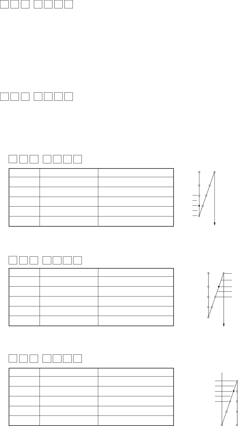
3 Compensation of off-timing of solenoid for reverse feed stitching at the end of sewing (Function setting No. 53)
Off-timing of solenoid for reverse feed stitching at the start of sewing can be compensated by the unit of angle.
Adjusting range
– 36 to 36 <1 / 10˚>
360˚
180˚
0˚
– 180˚
– 360˚
!7 Compensation of timing of the solenoid for reverse feed stitching (Function setting No. 51 to 53)
When the normal and reverse feed stitches are not uniform under the automatic reverse feed stitching action, this
function can change the ON / OFF timing of the solenoid for back tack and compensate the timing.
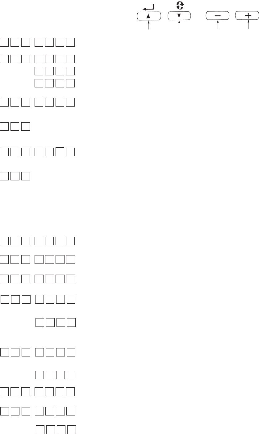
1 Compensation of on-timing of solenoid for reverse feed stitching at the start of sewing (Function setting No. 51)
On-timing of solenoid for reverse feed stitching at the start of sewing can be compensated by the unit of angle.
Adjusting range
– 36 to 36 <1 / 10˚>
Set value Compensation angle
Number of sitches of compensation
– 36 – 360˚ – 1
– 18 – 180˚ – 0.5
00˚ 0
18 180˚ 0.5
36 360˚ 1
*When the point
before 1 stitch is
regarded as 0˚,
compensation is
possible by 360˚ (1
stitch) in front and
in the rear.
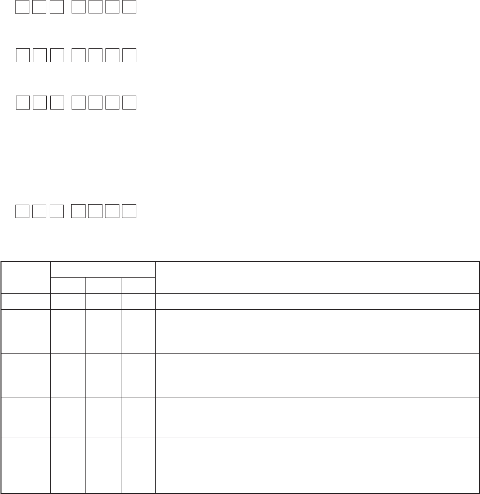
2 Compensation of off-timing of solenoid for reverse feed stitching at the start of sewing (Function setting No. 52)
Off-timing of solenoid for reverse feed stitching at the start of sewing can be compensated by the unit of angle.
Adjusting range
– 36 to 36 <1 / 10˚>
360˚
180˚
0˚
– 180˚
– 360˚
Set value Compensation angle
Number of sitches of compensation
– 36 – 360˚ – 1
– 18 – 180˚ – 0.5
00˚ 0
18 180˚ 0.5
36 360˚ 1
Set value Compensation angle
Number of sitches of compensation
– 36 – 360˚ – 1
– 18 – 180˚ – 0.5
00˚ 0
18 180˚ 0.5
36 360˚ 1
– 360˚
– 180˚
0˚
180˚
360˚
51 10
52 16
53 18
38 2500
47 60

− 30 −
@2
Function of stop immediately after the reverse feed stitching at the start of sewing (Function setting No. 60)
This function temporarily stops the sewing machine even when keeping depressing the front part of the pedal
at the time of completion of process of reverse feed stitching at the start of sewing.
It is used when sewing a short length by reverse feed stitching at the start of sewing.
0 : Not provided with the function of
temporary stop of the sewing
machine immediately after the
reverse feed stitching at the start of
sewing
1 : Provided with the function of
temporary stop of the sewing
machine immediately after the
reverse feed stitching at the start of
sewing
Stop the sewing machine
temporarily to change direction
of sewing products.
@1 Change-over function of AUTO / Pedal for sewing speed of the reverse feed stitching at the start of
sewing (Function setting No. 59)
This function selects whether the reverse feed stitching at the start of sewing is performed without a break at
the speed set by the function setting No. 8 or the stitching is performed at the speed by the pedal operation.
0 : Manu The speed is indicated by the pedal operation.
1 : Auto Automatic stitching at the specified speed
(Caution) 1. The max. sewing speed of the reverse feed stitching at the start of sewing is limited to
the speed set by the function setting No. 8 regardless of the pedal.
2. When “0” is selected, stitches of reverse feed stitching may not match those of normal
feed stitching.
@0 Function of holding predetermined upper / lower position of the needle bar (Function setting No. 58)
When the needle bar is in the upper position or in the lower position, this function holds the needle bar by
applying a brake slightly.
0 : off Function of holding predetermined upper/lower position of the needle
bar is ineffective.
1 : on Function of holding predetermined upper/lower position of the needle
bar is effective.
2 : on Function of holding predetermined upper/lower position of the needle
bar is ineffective.
3 : on Function of holding predetermined upper/lower position of the needle
bar is effective.
!8 Foot lift function after thread trimming (Function setting No. 55)
This function can automatically lift the presser foot after thread trimming.This function is effective only when
it is used in combination with the AK device.
0 : off Function of automatically lifting the presser foot is not provided.
(Presser foot does not automatically go up after thread trimming.)
1 : on Function of automatically lifting the presser foot is provided.
(Presser foot automatically goes up after thread trimming.)
!9 Reverse revolution to lift the needle after thread trimming (Function setting No. 56)
This function is used to make the sewing machine rotate in the reverse direction after thread trimming to lift
the needle bar almost to highest position. Use this function when the needle appears under the presser foot
and it is likely to make scratches on the sewing products of heavy-weight material or the like.
0 : off Function of making the sewing machine rotate in the reverse direction
to lift the needle after thread trimming is not provided.
1 : on Function of making the sewing machine rotate in the reverse direction
to lift the needle after thread trimming is provided.
(Caution) The needle bar is raised, by rotating the machine in the reverse direction, almost to the
highest dead point. This may result in slip-off of the needle thread. It is therefore necessary
to adjust the length of thread remaining after thread trimming properly.
58 0
59 1
60 0
55 1
56 0
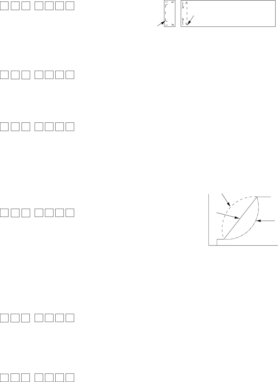
− 31 −
@3 Function of reducing speed of reverse feed stitching at the start of sewing (Function setting No. 92)
Function to reduce speed at the time of completion of reverse feed stitching at the start of sewing : Normal
use depending on the pedal condition (Speed is acceralated to the highest without a break.)
This function is used when temporary stop is used properly. (Cuff and cuff attaching)
0 : Speed is not reduced.
1 : Speed is reduced. Sew without stopping
without a break.
Temporary stop
@7 Function added to the needle up / down compensating switch (Function setting No. 93)
One stitch operation can be performed only when the needle up / down compensating switch is pressed at the
time of upper stop immediately after turning ON the power switch or upper stop immediately after thread
trimming.
0 : Normal (Only needle up / down compensating stitching operation)
1 : One stitch compensating stitching operation (upper stop / upper stop)
is performed only when aforementioned changeover is made.
@6 Function of pedal curve selection (Function setting No. 87)
This function can perform the selection of the curve of number of rotation of the sewing machine against the
depressing amount of the pedal.
Change to this function when you feel that inching operation is hard or that pedal response is slow.
0 : Number of rotation of the sewing machine
in terms of the depressing amount of the
pedal increases linearly.
1 : Reaction to intermediate speed in terms
of the depressing amount of the pedal is
delayed.
2 : Reaction to intermediate speed in terms
of the depressing amount of the pedal is
advanced.
@5 One-shot function up to material end (Function setting No. 76)
This function can perform the one-shot automatic stitching up to the end of material in combination with the
material end sensor when the operation panel is not connected.
0 : Without one-shot function
1 : With one-shot function
@4 Retry function (Function setting No. 73)
When the retry function is used, if the sewing material is thick and not piereced with needle, this function
makes the needle pierce in the material with ease.
0 : Normal
1 : Retry function is provided.
Number of rotation (rpm)
Pedal stroke (mm)
0
1
2
@8 Setting of max. number of rotation of the sewing machine head (Function setting No. 96)
This function can set the max. number of rotation of the sewing machine head you desire to use.
Upper limit of the set value varies in accordance with the sewing machine head to be connected.
150 to Max. [rpm] <50 / rpm>
87 0
96 4000
93 0
76 0
92 0
73 1
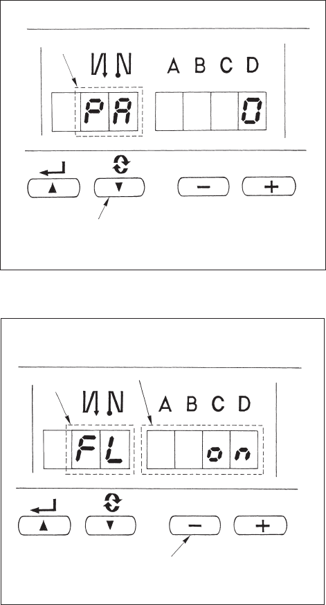
− 32 −
6. Automatic compensation of neutral point of the pedal sensor
Whenever the pedal sensor, spring, etc. are replaced, be sure to perform following operation :
1) Pressing switch 2, turn ON the power switch.
2) Indication on the screen will be as illustrated in 6.
At this time, the value indicated in the 7 segments
of four figures is the compensation value.
(Caution) At this time, the pedal sensor does not
work properly if the pedal is depressed. Do
not place the foot or any object on the
pedal. Warning sound “peeps” and the
compensation value is not displayed.
3) Turn OFF the power switch, and turn ON the power
switch again to return to the normal mode.
7. Setting of the auto lifter function
When the auto-lifter device (AK) is attached, this
function makes the function of auto-lifter work.
1) Turn ON the power switch while pressing switch
3 inside the control box.
2) LED display is turned to 5, 6 (FL ON) with “beep”,
and the function of auto-lifter becomes effective.
3) Turn OFF the power switch, and turn ON the power
switch again to return to the normal mode.
4) Repeat the operation 1) to 3), and LED display is
turned to (FL OFF). Then, the function of auto-lifter
does not work.
FL ON : Auto-lifter device becomes effective.
FL OFF : Auto-lifter function does not work.
(Standard at the time of delivery)
(Similarly, the presser foot is not automatically lifted
when programmed stitching is completed.)
(Caution) 1. To perform re-turning ON of the power, be sure to perform after the time of one second
or more has passed.
(If ON / OFF operation of the power is performed quickly, setting may be not changed
over well.)
2. Auto-lifter is not actuated unless this function is properly selected.
3. When “FL ON” is selected without installing the auto-lifter device, starting is
momentarily delayed at the start of sewing. In addition, be sure to select “FL OFF”
when the auto-lifter is not installed since the touch-back switch may not work.
56
3
6
2

− 33 −
8. Initialization of the setting data
All contents of function setting of SC-510 can be
returned to the standard set values.
1) Pressing all switches 2, 3 and 4, turn ON the
power switch.
2) LED displays indication 6 with the sound “peep”,
and initialization starts.
3) The buzzer sounds after approximately one second
(single sound three times, “peep”, “peep”, and
“peep”), and the setting data returns to the standard
setting value.
(Caution) Do not turn OFF the power on the way
of initializing operation. Program of the
main unit may be broken.
4) Turn OFF the power switch, and turn ON the power
switch again to return to the normal mode.
(Caution)
1. When this operation is performed, the
neutral compensation value of the pedal
sensor becomes “0”. Accordingly, be sure
to execute the operation of automatic pedal
sensor neutral compensation before using
the sewing machine. (Refer to page 32.)
2. Even when this operation is performed, the
sewing data set by the operation panel
cannot be initialized.
$. MAINTENANCE
1. Replacing the fuse
WARNING :
To prevent personal injuries caused by electric shock hazards or abrupt start of the sewing machine,
remove the cover after turning OFF the power switch and a lapse of 5 minutes or more. To prevent
personal injuries, when a fuse has blown out, be sure to replace it with a new one with the same
capacity after turning OFF the power switch and removing the cause of the blown-out of the fuse.
1) Press the OFF button of the power switch to turn
OFF the power after confirming that the sewing
machine has stopped.
2) Draw out the power cord coming from the power
plug socket after confirming that the power switch
is turned OFF. Perform the work of step 3) after
confirming that the power has been cut and it has
passed for 5 minutes or more.
6
234
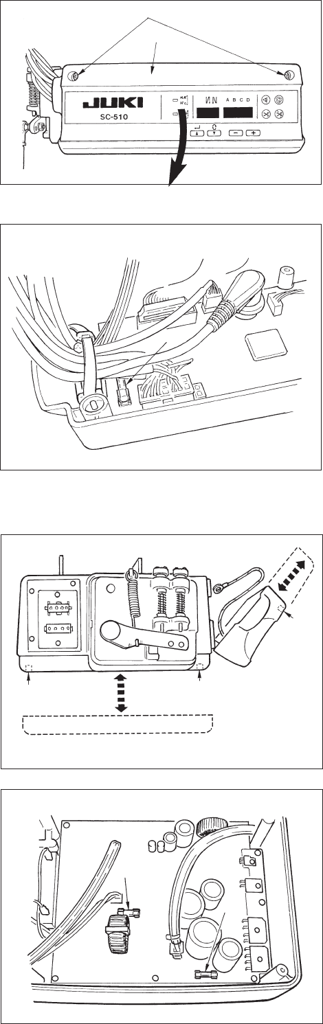
− 34 −
1
2
F1
F2
F1
[ Replacing F1 fuse on CTL circuit board (solenoid protection fuse) ]
1) Loosen two setscrews in the front cover and open
the cover after checking that the power has been
turned OFF.
2) Replace 5A F1 fuse on CTL circuit board with a
fuse of the same capacity supplied as accessories.
3) Close the front cover as before and fix it with the
setscrews while paying attention to pinching of the
cords.
[ Replacing F1 fuse on PWR circuit board (power circuit protection fuse) ]
[ Replacing F2 fuse on PWR circuit board (regenerative resistance protection fuse) ]
1) Loosen two setscrews in the front cover and open
the cover after checking that the power has been
turned OFF.
2) Remove connectors CN30, CN32, CN33, CN36,
CN37 and CN38 and remove the setscrew attached
to the ground wire of CTL circuit board. (Connector
Nos. depend on the specifications.)
3) Draw up the front cover obliquely at the position
where the front cover is obliquely tilted by
approximately 45 degrees, and remove the cover.
Remove the control box from the motor.
4) Remove four setscrews in the bottom cover and
remove the bottom cover.
5) Replace 3.15A F1 fuse or 2A F2 fuse on PWR
circuit board with a fuse of the same capacity
supplied as accessories.
6) Fix the bottom cover as before with the setscrews,
and press the front cover to the bottom cover from
the position where the front cover is obliquely tilted
by approximately 45 degrees for assembling.
7) Attach the connectors and the ground wire which
have been removed.
8) Close the front cover as before and fix it with the
setscrews while paying attention to pinching of the
cords.
3) Loosen setscrew 1 in front cover 2.
4) Pressing the side of front cover 2 in the direction
of the arrow, open the front cover toward you.
Note : Be sure to open / close the front cover with
your hands.
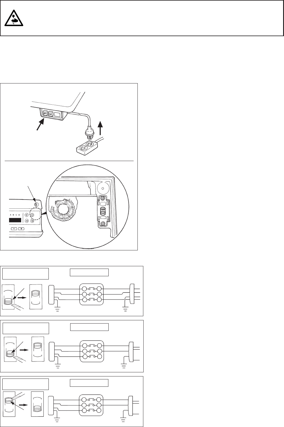
− 35 −
110V
220V
110V
220V
220V
1
A
A
A
110V
2. Changing procedure between 100V to 120V and 200V to 240V
(Possible only for the voltage changeover type)
Voltage can be changed between single phase 100 to 120V and single phase/3-phase 200 to 240V by
changing over the voltage changeover switch.
(Caution) The voltage changeover switch is on the inside of the control box. When changing the setting, be
sure to open the front cover after turning OFF the power switch and a lapse of 5 minutes or more.
In addition, if the changing procedure is mistaken, the control box is damaged. So, be very careful.
1) Turn OFF the power with the power switch after
checking that the sewing machine has stopped.
2) Draw out the power cord from the power receptacle
after checking that the power switch has been
turned OFF. Then wait for 5 minutes or more.
3) Remove two screws 1 fixing the front cover and
slowly open the front cover.
4) hanging procedure of the power voltage
(Caution) When the voltage of the power changeover
switch and that of the AC input cord are
wrong, the control box is damaged.
Be sure to check the indication of the
changeover switch and the input power
voltage for use.
4)-1 When using with 3-phase 200 to 240V
¡Put a screwdriver or the like to the slit section
A of the changeover switch and push up the
switch.
(Indication of the voltage of switch is 220V.)
¡Connect the crimp style terminal of AC input cord
to the power plug as shown in the figure A.
4)-2 When using with single phase 200 to 240V
¡Put a screwdriver or the like to the slit section
A of the changeover switch and push up the
switch.
(Indication of the voltage of switch is 220V.)
¡Connect the crimp style terminal of AC input cord
to the power plug as shown in the figure B.
4)-3 When using with single phase 100 to 120V
¡ Put a screwdriver or the like to the slit section A of
the changeover switch and push down the switch.
(Indication of the voltage of switch is 110V.)
¡Connect the crimp style terminal of AC input cord
to the power plug as shown in the figure C.
(Caution) Be very careful that the components are not
damaged by the top end of the screwdriver.
5) Check again that the change has been performed
without fail before closing the front cover.
6) Close the front cover and tighten two screws while
being very careful that the cord is not caught by
the cover.
WARNING :
To prevent personal injuries caused by electric shock hazards or abrupt start of the sewing machine,
carry out the work after turning OFF the power switch and a lapse of 5 minutes or more. To prevent
accidents caused by unaccustomed work or electric shock, request the electric expert or engineer of
our dealers when adjusting the electrical components.
WHITE
BLACK
WHITE
BLACK
RED
Plug side
GREEN/
YELLOW
GREEN/
YELLOW
RED
WHITE
BLACK
Plug side
GREEN/
YELLOW
RED
WHITE
BLACK
Plug side
GREEN/
YELLOW
RED
AC input cord
Voltage
changeover switch
AC input cord
Voltage
changeover switch
AC input cord
Voltage
changeover switch
Fig. A
Fig. B
Fig. C
GREEN/
YELLOW
GREEN/
YELLOW

− 36 −
Phenomenon
When tilting the sewing machine, the
buzzer beeps and the sewing
machine cannot be operated.
Solenoids for thread trimming,
reverse feed, wiper, etc. fail to work.
Hand lamp does not light up.
Even when depressing the pedal
immediately after turning ON the
power, the sewing machine does not
run. When depressing the pedal after
depressing the back part of pedal
once, the sewing machine runs.
The sewing machine does not stop
even when the pedal is returned to
its neutral position.
Stop position of the sewing machine
varies (irregular).
Presser foot does not go up even
when auto-lifter device is attached.
Touch-back switch fails to work.
UP position move fails to work when
all lamps on the panel light up.
Sewing machine fails to run.
Cause
When tilting the sewing machine
without turning OFF the power switch,
Action given on the left side is taken
for safety sake.
When the fuse for solenoid power
protection has blown out
Neutral position of the pedal has
varied.
(Neutral position may be shifted when
changing spring pressure of the pedal
or the like.)
When tightening the screw in the
handwheel is forgotten at the time of
adjustment of needle stop position.
Auto-lifter function is OFF.
Pedal system is set to KFL system.
Cord of auto-lifter device is not
connected to connector (CN37).
Presser foot is going up by auto-liter
device.
Auto-lifter device is not attached.
However, auto-lifter function is ON.
The mode is in the function setting mode.
The switch on the CTL p.c.b. is pressed
by the bound cords and the
aforementioned mode resulted.
Motor output cord (4P) is disconnected.
Connector (CN30) of motor signal cord
is disconnected.
Corrective measure
Tilt the sewing machine after turning OFF
the power.
Check the fuse for solenoid power
protection.
Execute the automatic neutral correction
function of the pedal sensor.
Securely tighten the screw in the
handwheel.
Select “FL ON” by auto-lifter function
selection.
Change the jumper to PFL setting to lift
the presser foot by depressing the back
part of the pedal.
Connect the cord properly.
Operate the switch after the presser foot
lowered.
Select “FL OFF” when auto-lifter device is
not attached.
Remove the front cover, and arrange the
cords by the regular binding procedure
described in the Instruction Manual.
Connect the cord properly.
Connect the cord properly.
3. Error codes
In case of the following, check again before you judge the case as trouble.

− 37 −
In addition, there are the following error codes in this device. These error codes interlock (or limit function) and inform the problem so
that the problem is not enlarged when any problem is discovered. When you request our service, please confirm the error codes.
Checking procedure of the error code
1) Pressing switch 1 in the control box, turn ON the power switch.
2) LED becomes display 5 with the sound of “peep” and
the latest error code is displayed.
3) Confirmation of the contents of previous error can be
performed by operating switches 1 or 2.
(Caution) When operating switch 1, one before the
existing error code is displayed.
When operating switch 2, one after the existing
error code is displayed.
Error code list
No.
E000
E003
E004
E005
E906
E007
E008
E811
E813
E924
E730
E731
Description of error detected
Execution of data initialization
(This is not the error.)
Disconnection of synchronizer
connector
Synchronizer lower position
sensor failure
Synchronizer upper position
sensor failure
Operation panel transmission
failure
Overload of motor
Machine head connector
failure(Resistance pack)
Overvoltage
Low voltage
Motor driver failure
Encoder failure
Motor hole sensor failure
Cause of occurrence expected
•When the machine head is changed.
•When the initialization operation is executed
•When position detection signal is not input
from the sewing machine head
synchronizer.
• When the synchronizer has broken.
•Disconnection of operation panel cord
•Operation panel has broken.
•When the machine head is locked.
•When sewing extra-heavy material beyond
the guarantee of the machine head.
•When the motor does not run.
•Motor or driver is broken.
•When the machine head connector is not
properly read.
•When voltage higher than guaranteed one
is inputted.
•220V has been inputted to SC-510 of 110V
specifications.
•400V is applied to the box of 220V (230V).
•When voltage lower than guaranteed one
is inputted.
•110V has been inputted to SC-510 of 220V
specifications.
•110V is applied to the box of 220V.
•Inner circuit is broken by the applied
overvoltage
•Motor driver has broken.
•When the motor signal is not properly
inputted.
Items to be checked
•Check the synchronizer connector (CN33, CN43)
for loose connection and disconnection.
•Check whether the synchronizer cord has broken
since the cord is caught in the machine head.
•Check the operation panel connector (CN38) for
loose connection and disconnection.
•Check whether the operation panel cord has
broken since the cord is caught in the machine
head.
•Check whether the thread has been entangled in
the motor pulley.
•Check the motor output connector (4P) for loose
connection and disconnection.
•Check whether there is any holdup when turning
the motor by hand.
•Check the machine head connector (CN32) for
loose connection and disconnection.
• Check whether the applied power voltage is higher
than the rated voltage + (plus) 10% or more.
• Check whether 110V/220V changeover switch is
improperly set.
In the aforementioned cases, POWER p.c.b is
broken.
•Check whether the voltage is lower than the rated
voltage – (minus) 10% or less.
• Check whether 110V/220V changeover switch is
improperly set.
•Check whether fuse or regenerative resistance is
broken.
•Check the motor signal connector (CN30) for loose
connection and disconnection.
•Check whether the motor signal cord has broken
since the cord is caught in the machine head.
5
12
ContentsContents
