ACOEM EGL1101 GATEWAY FOR RADIO FREQUENCY SENSOR User Manual Eagle
ACOEM GATEWAY FOR RADIO FREQUENCY SENSOR Eagle
ACOEM >
Contents
- 1. User manual 1 - 2AC3Z-EGL1101.pdf
- 2. User manual 2 - 2AC3Z-EGL1101.pdf
- 3. User Manual Attestation statement - 2AC3Z-EGL1101.pdf
User manual 1 - 2AC3Z-EGL1101.pdf

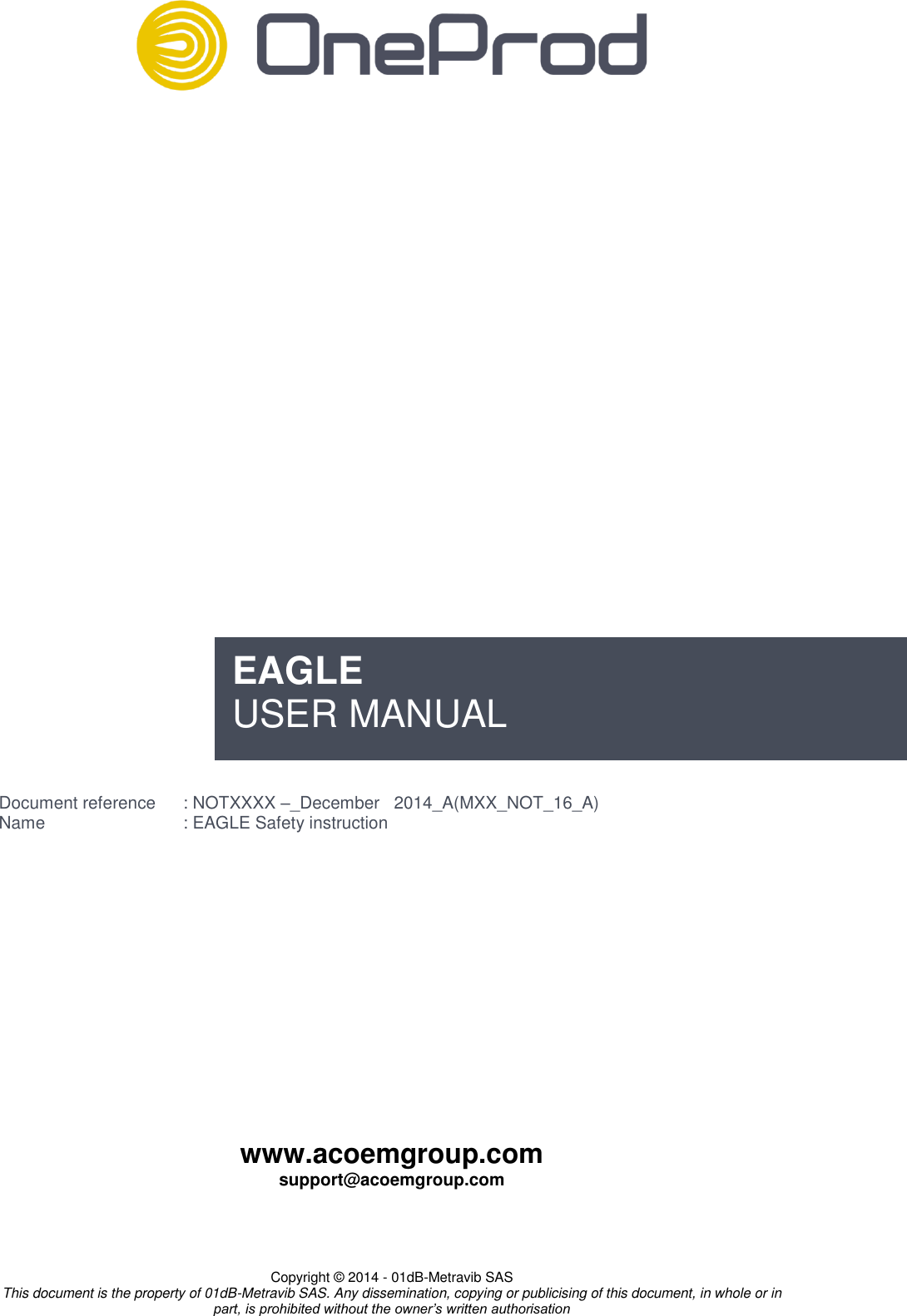
![6 www.acoemgroup.com support@acoemgroup.com Copyright © 2014 - 01dB-Metravib SAS This document is the property of 01dB-Metravib SAS. Any dissemination, copying or publicising of this document, in whole or in part, is prohibited without the owner’s written authorisation 2.4. PRIMARY CELL Caution: Risk of explosion if battery is replaced by an incorrect type. Dispose of used batteries according to the manufacturer's instructions. Only use SAFT LS33600 3.6 V primary lithium-thionyl chloride (Li-SOCl2) D-size bobbin cell Use of any other battery causes risk of explosion CAUTION: The battery must be installed in the direction indicated by the polarity symbol. Figure 2 : polarity symbol Only replace the primary cell in a safe area WARNING: Risk of exposure exists in case of mechanical, electrical or thermal abuse. Accordingly, do not short circuit, recharge, incinerate, puncture, crush, immerse in any liquids, force discharge, heat above the operating temperature range of the product or solder directly to the cell. In such instances, there is risk of fire, explosion and burn hazard. 2.5. STORAGE The storage area should be clean, cool (not exceeding +25°C [+77°F]), dry and ventilated. Storage at high temperature will lead accelerated degradation of the primary cell. CAUTION: Do not leave Eagle devices exposed to a heat source or high temperature location such as an unattended vehicle. To prevent damage, remove the devices from the vehicle. 2.6. TRANSPORTATION For transportation, follow procedure UN3091 (cells and batteries contained in equipment or packed with it) for Class 9 Miscellaneous Dangerous Goods and use UN Identification Number labels that are clearly visible on the outer packaging. Primary cell must be transported inside the sensors or expanders. Table 3: primary cell information for transportation Li metal in cell (g) 4.5 g [0.16 oz] Net Cell Mass 90 g [3.17 oz] UN Number UN 3091 (cells and batteries contained in equipment or packed with it) Packing Group ll D.C Class Section IA Class 9](https://usermanual.wiki/ACOEM/EGL1101.User-manual-1-2AC3Z-EGL1101-pdf/User-Guide-2553673-Page-10.png)
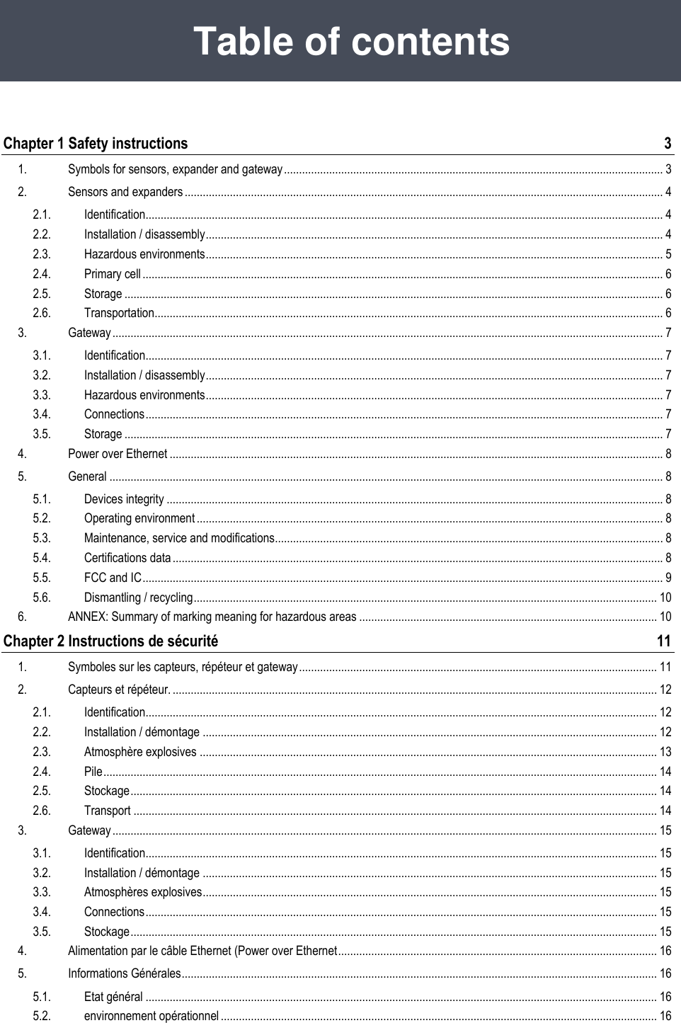
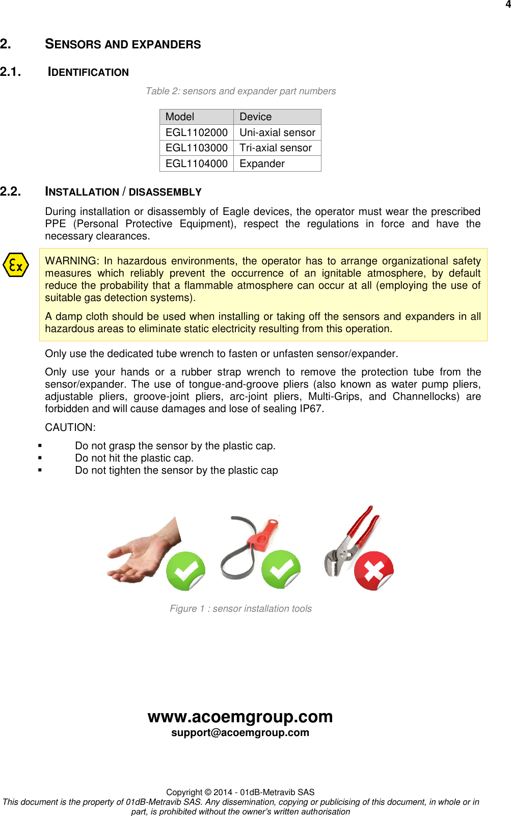
![www.acoemgroup.com support@acoemgroup.com Copyright © 2014 - 01dB-Metravib SAS This document is the property of 01dB-Metravib SAS. Any dissemination, copying or publicising of this document, in whole or in part, is prohibited without the owner’s written authorisation 3. GATEWAY 3.1. IDENTIFICATION Table 4: gateways part numbers Model Device EGL1101000 Gateway with embedded antenna EGL1105000 Gateway with external antenna 3.2. INSTALLATION / DISASSEMBLY During installation or disassembly of Eagle devices, the operator must wear the prescribed PPE (Personal Protective Equipment), respect the regulations in force and have the necessary clearances. WARNING: In hazardous environments, the operator has to arrange organizational safety measures which reliably prevent the occurrence of an ignitable atmosphere, by default reduce the probability that a flammable atmosphere can occur at all (employing the use of suitable gas detection systems). A damp cloth should be used when installing or taking off the gateway in hazardous areas to eliminate static electricity resulting from this operation. 3.3. HAZARDOUS ENVIRONMENTS II 3 G Ex ic IIC T4 Gc -20°C < Ta <+60°C [-4°F< Ta <140°F] (Pending) LCIE 14 ATEX xxxx X (Pending) IECEx LCIE 14.xxxxX (Pending) 3.4. CONNECTIONS In zone 2 hazardous environments, before connecting or disconnecting the Ethernet cable to the gateway, always ensure the following: The Ethernet cable must not be connected to the other end. The operator has to prevent the occurrence of an ignitable atmosphere (employing the use of suitable gas detection systems). Do not exceed maximum input voltage and current on the Ethernet connector: Maximum input voltage is 48 V DC – 0.3 A 3.5. STORAGE The storage area should be clean, cool (not exceeding +25°C [+77°F]), dry and ventilated. Do not leave Eagle devices exposed to a heat source or high temperature location such as an unattended vehicle. To prevent damage, remove the devices from the vehicle.](https://usermanual.wiki/ACOEM/EGL1101.User-manual-1-2AC3Z-EGL1101-pdf/User-Guide-2553673-Page-11.png)
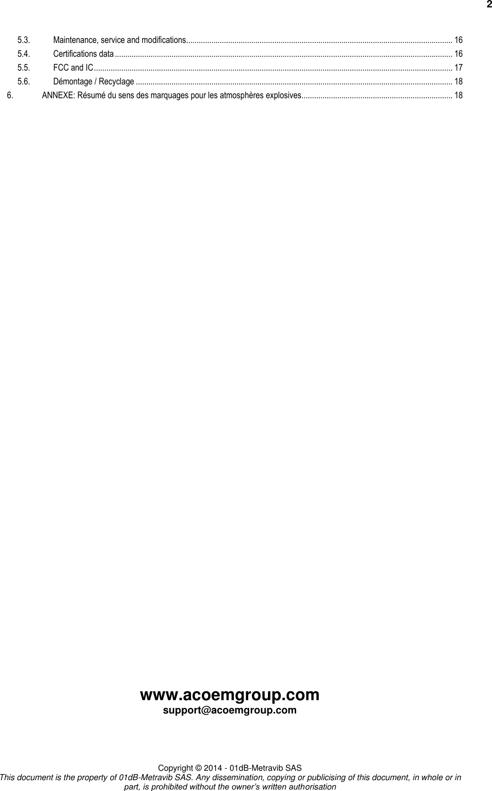
![8 www.acoemgroup.com support@acoemgroup.com Copyright © 2014 - 01dB-Metravib SAS This document is the property of 01dB-Metravib SAS. Any dissemination, copying or publicising of this document, in whole or in part, is prohibited without the owner’s written authorisation 4. POWER OVER ETHERNET The POE is the power supply. The power supply POE is the main disconnecting device in the system and, as such, should remain always perfectly accessible and disconnectable. Alternatively, a switch on the power supply line, permanently accessible, can also constitute the main disconnecting device. Only use the PoE injector sold or recommended by OneProd to power up the gateway. PoE injector is fully compliant with IEEE802.3.af Outputs are equipped with short circuit protection and overload protection as per IEEE 802.3af specification. Only use the power cord adapted to your country. 5. GENERAL 5.1. DEVICES INTEGRITY Before use, check devices, cables and accessories integrity. Check that enclosures are not cracked, broken or abnormally distorted. Check the condition of the opening plug of the ethernet port of the gateway. Check that sensors and expanders are tightened In case of a defect, have the defective part(s) replaced. Disconnect the power of the Gateway. 5.2. OPERATING ENVIRONMENT Eagle devices are designed to operate in normal environmental conditions as described in standard IEC60950: Altitude up to 2,000 m [6,500 ft] Temperature from -20°C to +70°C [-4°F/158°F] (non hazardous environments) Pollution rating 2 (Only non-conductive pollution occurs except that occasionally a temporary conductivity caused by condensation is to be expected.) < 95% relative humidity non-condensing Indoor & outdoor use for EGL1101000 (internal antenna) Indoor only for EGL1105000 (internal antenna). 5.3. MAINTENANCE, SERVICE AND MODIFICATIONS Service operations are prohibited by persons other than OneProd staff Only the battery replacement may be performed by the end user It is forbidden to make any changes to the products. Any change causes the loss of all compliance certifications for this product. It is strictly forbidden to open gateway's enclosure. Disconnect the PoE injector of the Gateway before maintenance. 5.4. CERTIFICATIONS DATA Eagle system has been qualified to ensure EMC, intrinsically safe and personal safety. Refer to EC certificate.](https://usermanual.wiki/ACOEM/EGL1101.User-manual-1-2AC3Z-EGL1101-pdf/User-Guide-2553673-Page-12.png)
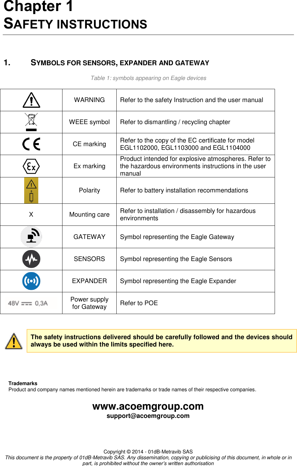
![10 www.acoemgroup.com support@acoemgroup.com Copyright © 2014 - 01dB-Metravib SAS This document is the property of 01dB-Metravib SAS. Any dissemination, copying or publicising of this document, in whole or in part, is prohibited without the owner’s written authorisation RF exposure: This device complies with Industry Canada licence-exempt RSS standard(s). Operation is subject to the following two conditions: (1) this device may not cause interference, and (2) this device must accept any interference, including interference that may cause undesired operation of the device. 5.6. DISMANTLING / RECYCLING The disposal or recycling of batteries must comply with the applicable directives of your country. The disposal or recycling of the Eagle devices must be in accordance with the valid directive on waste electrical and electronic equipment (WEEE) (2012/19/EC). Gateway, sensor, expander and their accessories should be recycled as electronic products including a battery. Gateway, sensor, expander and their accessories should not be burnt or thrown into fire. Gateway, sensor, expander and their accessories should not be disposed in a dump. 6. ANNEX: SUMMARY OF MARKING MEANING FOR HAZARDOUS AREAS The information below is general and should consulted beings as such. Read carefully the labeling of each product. Product intended for explosive atmospheres I / II Applications I = Mining industry applications II = Surface industry applications 1 / 3 Explosive zones for surface industry 1 = intended for Zone 0 (gas) with a permanent explosive atmosphere. EPL level Ga. 3 = intended for Zone 2 (gas) where an explosive atmosphere may only appear accidentally, in case of malfunction of the installation. EPL level Gc. M1 Explosive zone for mining industry Zone 0 (gas) with a permanent explosive atmosphere. G Gas atmosphere Ex Protection against explosions ia / ic Protection modes intended to prevent explosion ia for flammable material always present or for long periods Zone 0 ic for Irregular / short term presence of gas (abnormal) Zone 2 IIC Devices intended to operate in presence of the most explosive substances: hydrogen, acetylene, ethyl nitrate … IIC product is automatically suitable for groups IIA and IIB. Ga / Gc Equipment protection level EPL A = for permanent or frequent presence of gaz (zone 0) EPL C = for Irregular / short term / abnormal presence of gas (zone 2) T4 Gas surface temperature pour an ambiante temperature Ta. < 135°C [275°F] pour -xx°C<Ta and +xx°C LCIE ATEX certificate number provided by notified body (LCIE) IECEx Certificate of conformity to IEC standards (Certification scheme IECEX) X Indication of particular condition(s) of use](https://usermanual.wiki/ACOEM/EGL1101.User-manual-1-2AC3Z-EGL1101-pdf/User-Guide-2553673-Page-14.png)
![14 2.4. PILE Attention: risque d'explosion si la pile est remplacée par un type incorrect. Recycler les piles usagées selon les instructions du fabricant. N'utilisez que des pile SAFT LS33600 3,6 V lithium-chlorure de thionyle (Li-SOCl2) taille. L'utilisation de tout autre type de pile entraîne un risque d'explosion Attention: La batterie doit être installée dans le sens indiqué par le symbole de polarité. Figure 4 : symbole de polarité Attention: Ne remplacez la pile qu'en zone sure et en dehors des zones à atmosphère explosive. WARNING: Risk of exposure exists in case of mechanical, electrical or thermal abuse. Accordingly, do not short circuit, recharge, incinerate, puncture, crush, immerse in any liquids, force discharge, heat above the operating temperature range of the product or solder directly to the cell. In such instances, there is risk of fire, explosion and burn hazard. AVERTISSEMENT: un usage ou un mauvais traitement inapproprié de la pile peut conduire à une surchauffe ou un démarrage d'incendie pouvant provoquer de sérieux dommages pour l'utilisateur. Le consignes suivantes doivent êtres respectées: Ne pas court-circuiter, ne pas recharger, ne pas incinérer, ne pas percer, ne pas écraser, ne pas plonger dans des liquides. ne pas effectuer une décharge forcée, ne pas utiliser au-delà de la plage de température de fonctionnement du produit, ne pas souder directement sur la pile. 2.5. STOCKAGE La zone de stockage doit être propre, fraiche (ne dépassant pas + 25 ° C [+ 77 ° F]), sèche et aérée. Le stockage à haute température entraînera la dégradation de la cellule pile. ATTENTION: Ne pas laisser les appareils Eagle exposés à une source de chaleur ou à un emplacement à haute température comme un véhicule au soleil. Pour éviter tout dommage, retirez les dispositifs du véhicule. 2.6. TRANSPORT Pour le transport, suivre la procédure ONU 3091 (piles et batteries contenues dans un équipement ou emballées avec lui) pour la classe 9 marchandises diverses dangereuses et utiliser des étiquettes d'identification numérique de l'ONU qui sont clairement visibles sur l'emballage extérieur. La pile doit être transportée à l'intérieur des capteurs ou des répéteurs Table 8: >Informations sur la pile pour le transport Quantité de Li metal dans la pile (g) 4.5 g [0.16 oz] Masse nette de la pile 90 g [3.17 oz] Numéro UN UN 3091 (cells and batteries contained in equipment or packed with it) Groupe de conditionnement ll Classe D.C Section IA Classe 9](https://usermanual.wiki/ACOEM/EGL1101.User-manual-1-2AC3Z-EGL1101-pdf/User-Guide-2553673-Page-18.png)
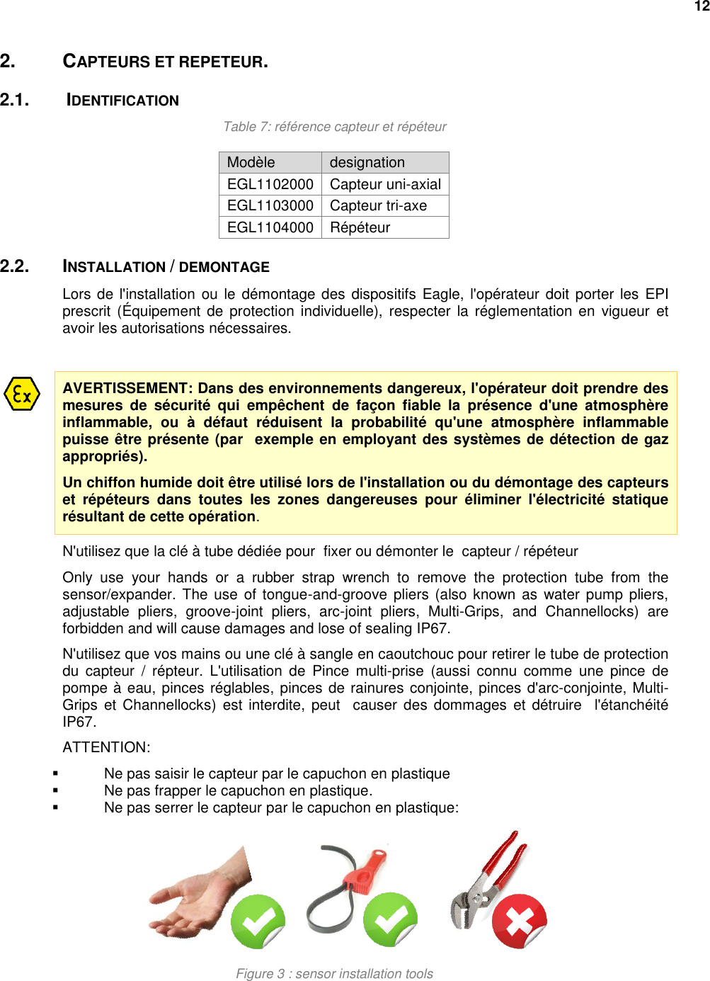
![3. GATEWAY 3.1. IDENTIFICATION Table 9: gateways part numbers Model Device EGL1101000 Gateway avec antenne interne EGL1105000 Gateway avec antenne externe 3.2. INSTALLATION / DEMONTAGE Lors de l'installation ou le démontage des dispositifs Eagle, l'opérateur doit porter les EPI prescrit (Équipement de protection individuelle), respecter la réglementation en vigueur et avoir les autorisations nécessaires. AVERTISSEMENT: Dans des environnements dangereux, l'opérateur doit prendre des mesures de sécurité qui empêchent de façon fiable la présence d'une atmosphère inflammable, ou à défaut réduisent la probabilité qu'une atmosphère inflammable puisse être présente (par exemple en employant des systèmes de détection de gaz appropriés). Un chiffon humide doit être utilisé lors de l'installation ou du démontage des capteurs et répéteurs dans toutes les zones dangereuses pour éliminer l'électricité statique résultant de cette opération. 3.3. ATMOSPHERES EXPLOSIVES II 3 G Ex ic IIC T4 Gc -20°C < Ta <+60°C [-4°F< Ta <140°F] (Pending) LCIE 14 ATEX xxxx X (Pending) IECEx LCIE 14.xxxxX (Pending) 3.4. CONNECTIONS En atmosphère explosive zone 2 la zone 2, avant de brancher ou de débrancher le câble Ethernet à la Gateway, toujours respecter les consigne suivantes: Le câble Ethernet ne doit pas être connecté à l'autre extrémité. L'opérateur doit empêcher l'apparition d'une atmosphère inflammable (par exemple en employant des systèmes de détection de gaz appropriés). Ne pas dépasser la tension d'entrée maximale et le courant sur le connecteur Ethernet: Tension d'entrée maximale est de 48 V DC - 0,3 A 3.5. STOCKAGE La zone de stockage doit être propre, fraiche (ne dépassant pas + 25 ° C [+ 77 ° F]), sèche et aérée. ATTENTION: Ne pas laisser les appareils Eagle exposés à une source de chaleur ou à un emplacement à haute température comme un véhicule au soleil. Pour éviter tout dommage, retirez les dispositifs du véhicule.](https://usermanual.wiki/ACOEM/EGL1101.User-manual-1-2AC3Z-EGL1101-pdf/User-Guide-2553673-Page-19.png)
![16 4. ALIMENTATION PAR LE CABLE ETHERNET (POWER OVER ETHERNET Le POE constitue l'alimentation de la Gateway. L'alimentation POE est le dispositif de sectionnement principal dans le système et, comme tel, doit rester toujours parfaitement accessible et déconnectable. Alternativement, un interrupteur sur la ligne d'alimentation, accessible en permanence, peut également constituer le dispositif de déconnexion principal. N'utilisez que l'alimentation PoE vendu ou recommandé par OneProd pour alimenter la passerelle. L'alimentation PoE est entièrement compatible avec IEEE802.3.af Les sorties sont équipés d'une protection de court-circuit et de protection contre les surcharges selon les spécifications de la norme IEEE 802.3af. N'utiliser que le cordon d'alimentation adapté à votre pays. 5. INFORMATIONS GENERALES 5.1. ETAT GENERAL Avant utilisation, Vérifier l'intégrité des dispositifs, câbles et accessoires. Vérifiez que les enveloppes ne sont pas fissurées, brisés ou anormalement déformées. Contrôler l'état du connecteur du port Ethernet de la Gateway. Vérifiez que les capteurs et les répéteurs sont serrés En cas de défaut, débranchez l'alimentation de la passerelle et procéder au remplacement de la pièce défectueuse. 5.2. ENVIRONNEMENT OPERATIONNEL Les produits Eagle sont conçus pour fonctionner dans des conditions environnementales normales, comme décrit dans la norme IEC60950: Altitude jusqu'à 2000 m [6500 ft] Température de -20 ° C à + 70 ° C [-4 ° F / 158 ° F] (atmosphères non explosives) Degré de pollution 2 (seule une pollution non-conductrice a lieu, sauf, parfois, une conductivité temporaire provoquée par la condensation.) <95% d'humidité relative sans condensation Utilisation intérieur et extérieure pour EGL1101000 (antenne interne) Utilisation intérieure seulement pour EGL1105000 (antenne interne). 5.3. MAINTENANCE, SERVICE AND MODIFICATIONS Les opérations de service sont interdites par d'autres personnes autres que le personnel OneProd. L'intégralité des pièces de rechange doit être fournie par le fabricant. L'intégralité des pièces de rechange doit être fournie par le fabricant. Il est interdit d'apporter des modifications aux produits. Tout changement entraîne la perte de toutes les certifications de conformité pour ce produit. Il est strictement interdit d'ouvrir le boîtier de la Gateway. Débrancher l'injecteur PoE de la passerelle avant l'entretien. 5.4. CERTIFICATIONS DATA Le système Eagle est qualifié pour garantir la sécurité, la compatibilité électromagnétique et la sécurité . Consulter le certificat de conformité CE.](https://usermanual.wiki/ACOEM/EGL1101.User-manual-1-2AC3Z-EGL1101-pdf/User-Guide-2553673-Page-20.png)
![18 Exposition RF: Le présent appareil est conforme aux CNR d'Industrie Canada applicables aux appareils radio exempts de licence. L'exploitation est autorisée aux deux conditions suivantes : (1) l'appareil ne doit pas produire de brouillage, et (2) l'utilisateur de l'appareil doit accepter tout brouillage radioélectrique subi, même si le brouillage est susceptible d'en compromettre le fonctionnement. 5.6. DEMONTAGE / RECYCLAGE L'élimination ou le recyclage des batteries doivent se conformer aux directives en vigueur dans votre pays. L'élimination ou le recyclage des appareils Aigle doivent être en conformité avec la directive valide sur des déchets d'équipements électriques et électroniques (DEEE) (2012/19 / CE). Gateway, capteur, répéteur et leurs accessoires doivent être recyclés comme des produits électroniques, y compris une batterie. Gateway, capteur, répéteur et leurs accessoires ne doivent pas être brûlés ou jetés dans le feu. Gateway, capteur, répéteur et leurs accessoires ne doivent pas être jetés dans une décharge. 6. ANNEXE: RESUME DU SENS DES MARQUAGES POUR LES ATMOSPHERES EXPLOSIVES Les informations ci-dessous sont générales et doivent êtres consultées en tant que telles. Lire attentivement le marquage de chaque produit. Produit destiné aux atmosphères explosives I / II Applications I = applications pour les industries minières II = applications pour les industries de surface 1 / 3 Zones explosives pour l'industrie de surface 1 = destiné à la Zone 0 (gaz) avec une atmosphère explosive permanente. Niveau EPL Ga. 3 = destiné à la Zone 2 (gaz), où une atmosphère explosive ne peut apparaître accidentellement, en cas de dysfonctionnement de l'installation. Niveau EPL Gc M1 Zone explosive pour l'industrie minière Zone 0 (gaz) avec une atmosphère explosive permanente. G Atmosphère de gaz Ex Protection contre les explosions ia / ic modes de destinés à éviter une explosion ia pour atmosphère inflammable toujours présente ou pendant de longues périodes Zone 0 ic pour irrégulière / courte présence à long terme de gaz (anormale) Zone 2 IIC dispositifs destinés à fonctionner en présence de substances les plus explosives: l'hydrogène, le nitrate d'éthyle acétylène, .IIC inclue les gaz des groups IIA and IIB. Ga / Gc Niveau de protection EPL A = une présence permanente ou fréquente de gaz (zone 0) EPL C = pour irrégulière / court terme / présence anormale de gaz (zone 2) T4 Température de surface maximale pour une ambiante donnée < 135°C [275°F] pour -xx°C<Ta and +xx°C LCIE numéro de certificat fourni par un organisme notifié (LCIE) IECEx Certificat de conformité aux normes IEC (certification IECEx) X Indication de précaution particulière (s) d'utilisation](https://usermanual.wiki/ACOEM/EGL1101.User-manual-1-2AC3Z-EGL1101-pdf/User-Guide-2553673-Page-22.png)