Contents
- 1. User manual 1 - 2AC3Z-EGL1102.pdf
- 2. User manual 2 - 2AC3Z-EGL1102.pdf
- 3. User Manual Attestation statement - 2AC3Z-EGL1102.pdf
User manual 2 - 2AC3Z-EGL1102.pdf

EAGLE
USER MANUAL
ADAPTER LA
COUVERTURE A
EAGLE
EAGLE
User Manual

www.acoemgroup.com
support@acoemgroup.com
Copyright © 2014 - 01dB-Metravib SAS
This document is the property of 01dB-Metravib SAS. Any dissemination, copying or publicising of this document, in whole or in
part, is prohibited without the owner’s written authorisation
Document reference : MXX_NOT_13_D_DOCXXXX – December 2014D
Name : EAGLE User manual
EAGLE
USER MANUAL

Table of contents
Chapter 1 Presentation 7
1. Introduction .................................................................................................................................................................................. 8
1. General presentation ................................................................................................................................................................... 8
1.1. Eagle devices ......................................................................................................................................................................... 8
1.2. Eagle network ......................................................................................................................................................................... 9
1.3. Radio communication ........................................................................................................................................................... 10
1.4. Eagle accessories................................................................................................................................................................. 11
Chapter 2 Installation guide 14
1. Site survey ................................................................................................................................................................................. 15
1.1. Site Planning ......................................................................................................................................................................... 15
1.2. Field test ............................................................................................................................................................................... 16
2. Installation prerequisites ............................................................................................................................................................ 17
2.1. Safety .................................................................................................................................................................................... 17
2.2. Site survey ............................................................................................................................................................................ 17
2.3. Fastening support ................................................................................................................................................................. 17
2.4. Network and power ............................................................................................................................................................... 17
3. Gateway installation ................................................................................................................................................................... 18
3.1. Location ................................................................................................................................................................................ 18
3.2. Mount .................................................................................................................................................................................... 19
3.3. Connection to the gateway ................................................................................................................................................... 20
3.4. Connection to the PoE .......................................................................................................................................................... 21
3.5. Sizes ..................................................................................................................................................................................... 22
4. Sensors installation .................................................................................................................................................................... 23
4.1. Sensor Location .................................................................................................................................................................... 23
4.2. Mounting information for sensors ......................................................................................................................................... 23
5. Expander installation .................................................................................................................................................................. 30
5.1. Expander location ................................................................................................................................................................. 30
5.2. Expander mounting............................................................................................................................................................... 30
6. Battery replacement (sensors / expander) ................................................................................................................................. 33
7. Protections ................................................................................................................................................................................. 34
7.1. Fall protection ....................................................................................................................................................................... 34
7.2. Protective shield ................................................................................................................................................................... 35
Chapter 3 Operating manual 37
1. Usage ......................................................................................................................................................................................... 38
1.1. Power up the sensor and expander ...................................................................................................................................... 38
2. Eagle embedded processing ..................................................................................................................................................... 38
2.1. Parameters ........................................................................................................................................................................... 38
2.2. Signals .................................................................................................................................................................................. 40
Chapter 4 OLD EAGLE 42
1.1. Protections ............................................................................................................................................................................ 42
1.2. Network connection .............................................................................................................................................................. 42
2. Network architecture .................................................................................................................................................................. 43

Chapter 5 Common usage of Eagle 44
1. Configuration .............................................................................................................................................................................. 44
1.1. Time signal ........................................................................................................................................................................... 44
1.2. FFT ....................................................................................................................................................................................... 44
1.3. Parameters ........................................................................................................................................................................... 44
2. Periodicity................................................................................................................................................................................... 45
3. Autonomy ................................................................................................................................................................................... 45
Chapter 6 Gateway web interface 46
1. Connect to the gateway interface .............................................................................................................................................. 46
2. Monitor signal strength ............................................................................................................................................................... 46
Chapter 7 Radio Installation Guideline 47
1. Initial Site Survey ....................................................................................................................................................................... 47
2. Choose a Suitable Antenna ....................................................................................................................................................... 47
2.1. Radiation Pattern .................................................................................................................................................................. 47
Chapter 8 Appendix 1: Radio 50
Trademarks
Product and company names mentioned herein are trademarks or trade names of their respective companies.
6
Brand of ACOEM
Chapter 1
SAFETY INSTRUCTIONS
Refer to the safety manual instruction before connecting and using.
Refer to the safety manual instruction each time you see a symbol of the list below.
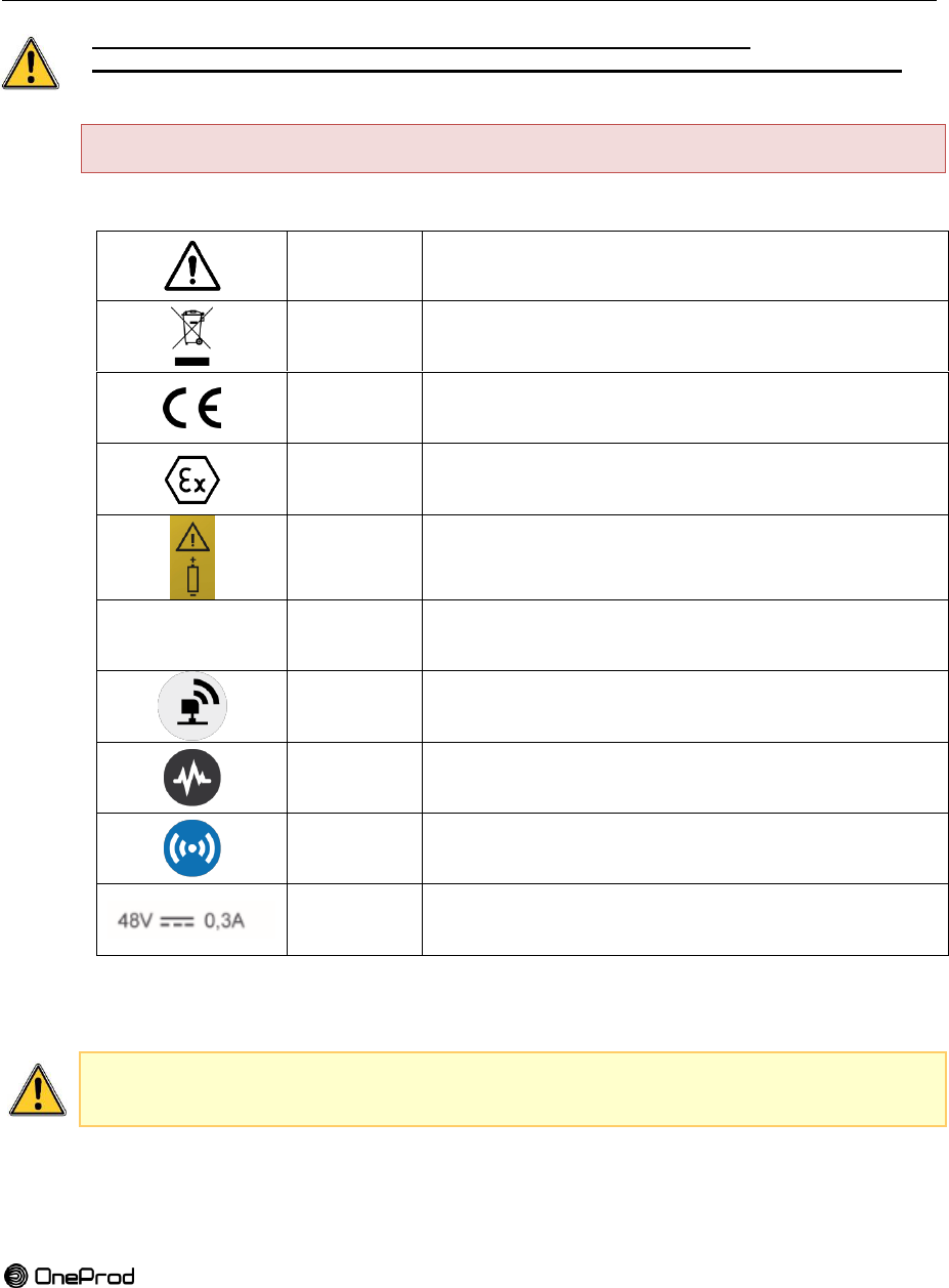
List of symbols for sensors, expander and gateway
Table 1: symbols appearing on Eagle devices
WARNING
Refer to the safety Instruction and the user manual
WEEE
symbol
Refer to dismantling / recycling chapter
CE marking
Refer to the copy of the EC certificate for model
EGL1101000, EGL1102000, EGL1103000 and
EGL1104000
Ex marking
Product intended for explosive atmospheres. Refer to
the hazardous environments instructions in the user
manual
Polarity
Refer to battery installation recommendations
X
Mounting
care
Refer to installation / disassembly for hazardous
environments
GATEWAY
Symbol representing the Eagle Gateway
SENSORS
Symbol representing the Eagle Sensors
EXPANDER
Symbol representing the Eagle Expander
Power
supply for
Gateway
Refer to POE
The safety instructions delivered should be carefully followed and the devices should
always be used within the limits specified here.

7
Brand of ACOEM
Chapter 1
PRESENTATION

8
Brand of ACOEM
1. INTRODUCTION
We want to congratulate you on your choice and hope that you will be fully satisfied with it.
For this reason, we recommend that you read carefully the present user manual and the
safety instructions.
Eagle is a smart wireless sensor that is easy to set up and allows you to continuously
monitor the health status of rotating machinery. Any manufacturer can enhance the reliability
of its production tools in the simplest way possible, freeing itself of the restrictions inherent in
setting up standard wired solutions.
Eagle guarantees a drastic reduction of installation costs in severe environments or where
preliminary engineering phases are necessary.
With its unique measurement capabilities, EAGLE is the first wireless solution without
compromise on diagnosis capabilities. All types of industrial rotating machines can be
monitored, thereby enabling you to increase the overall reliability of your industrial installed
base.
In case of a problem, please contact OneProd Hotline
support@acoemgroup.com
1. GENERAL PRESENTATION
1.1. EAGLE DEVICES
Figure 5 : Eagle system
Photo générale du système Eagle (Gateway, Expander,
Capteurs, alim., câbles
9
Brand of ACOEM
1.2. EAGLE NETWORK
La communication entre le PC et la Gateway se fait via un câble Ethernet cat 5e, en réseau
local uniquement. Ni le PC, ni la gateway ne peuvent se connecter à un réseau wifi ou
bluetooth environnant, ces services sont complètement arrêtés sur le PC et inexistant sur la
Gateway. Le réseau local de communication est physiquement séparé de tous réseaux
environant.
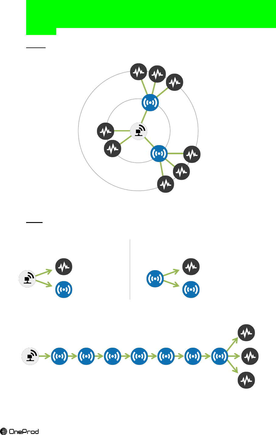
1.2.1.
Basics
Figure 6 : basic Eagle network
1.2.2.
Rules
Figure 7 : Eagle network rules
16 SENSORS
4 EXPANDERS
EXPANDER CONNECTIONS:
20 NODES DIRECTLY
GATEWAY CONNECTIONS:
30 NODES DIRECTLY
MULTI-HOPS CAPACITY: 8 HOPS
SENSORS
EXPANDERS

10
Brand of ACOEM
1.3. RADIO COMMUNICATION
1.3.1.
Characteristics
Parler de l’ISA100.11a
L’ensemble des produits utilise la bande de fréquence ISM 2.45GHz. Bande de fréquences
regroupant entre autre le wifi, bluetooth, zigbee... Cependant, la modulation utilisée par la
couche PHY (O-QPSK) ne permet pas de décoder physiquement les données wifi et
bluetooth, seulement les données 802.15.4 PHY.
Les capteurs émettent à +3dBm, soit 2mW et les éléments du réseau (routeur et gateway) à
+13dBm (20mW).
1.3.2.
Radio standard
L’ensemble des produits utilise le protocole radio 802.15.4e. Cela permet d’avoir de base
certaines sécurités quant aux échanges de données entre les différents éléments du réseau
radio. En effet, chaque élément du réseau possède une adresse MAC unique codée sur
64bits. Cette adresse identifie un capteur unique sur un réseau unique. De plus, pour qu’un
élément puisse rejoindre un réseau radio existant, il faut qu’il connaisse l’identifiant du
réseau, codé sur 16bits. Pour encore plus de sécurité, lors d’installation sensible comme en
milieu industriel, il est possible de rajouter une “liste blanche” sur la gateway, qui filtre sur
adresse MAC et n’accepte sur le réseau que les éléments présents dans cette liste.
1.3.3.
Radio coverage
En champ libre, les capteurs peuvent avoir une portée radio d’envrion 100m. En
environnement perturbé, et/ou industriel, la portée dépend énormément de l’environnement
et des essais sur place sont nécessaires. Une portée d’environ 20m est plus réaliste dans ce
type d’environnement. De même que pour les capteurs, la portée radio de la Gateway et des
routeurs est fortement dépendante de l’environnement.
1.3.4.
Security

11
Brand of ACOEM
1.4. EAGLE ACCESSORIES
Figure 8: Eagle accessories
Model
Description
EGL 1201 000
Power over ethernet PoE IEEE 802.3af
EGL 1202 000
Primary cell SAFT LS33600 Li-SOCl2, 3.6V, 1.7Ah, D cell
EGL 1203 000
O-ring seal NBR 70 SH Ø int 37,82mm x Ø tore 1,78mm (UL)
EGL 1204 000
Suitcase
EGL 1205 000
Special wrench for Eagle sensor/expander tightening
EGL 1206 000
Special tool for Eagle triaxial sensor orientation (use with ACA1029000)
EGL 1207 000
Galvanic isolator for hazardous environments
EGL 1208 000
Tough Ball-joint mounting for Eagle gateway
EGL 1209 000
Tough Ball-joint mounting for Eagle expander
EGL 1210 000
Eagle protective shield
EGL 1211 000
(Option) Fall protection ring for operating at height (off-shore)
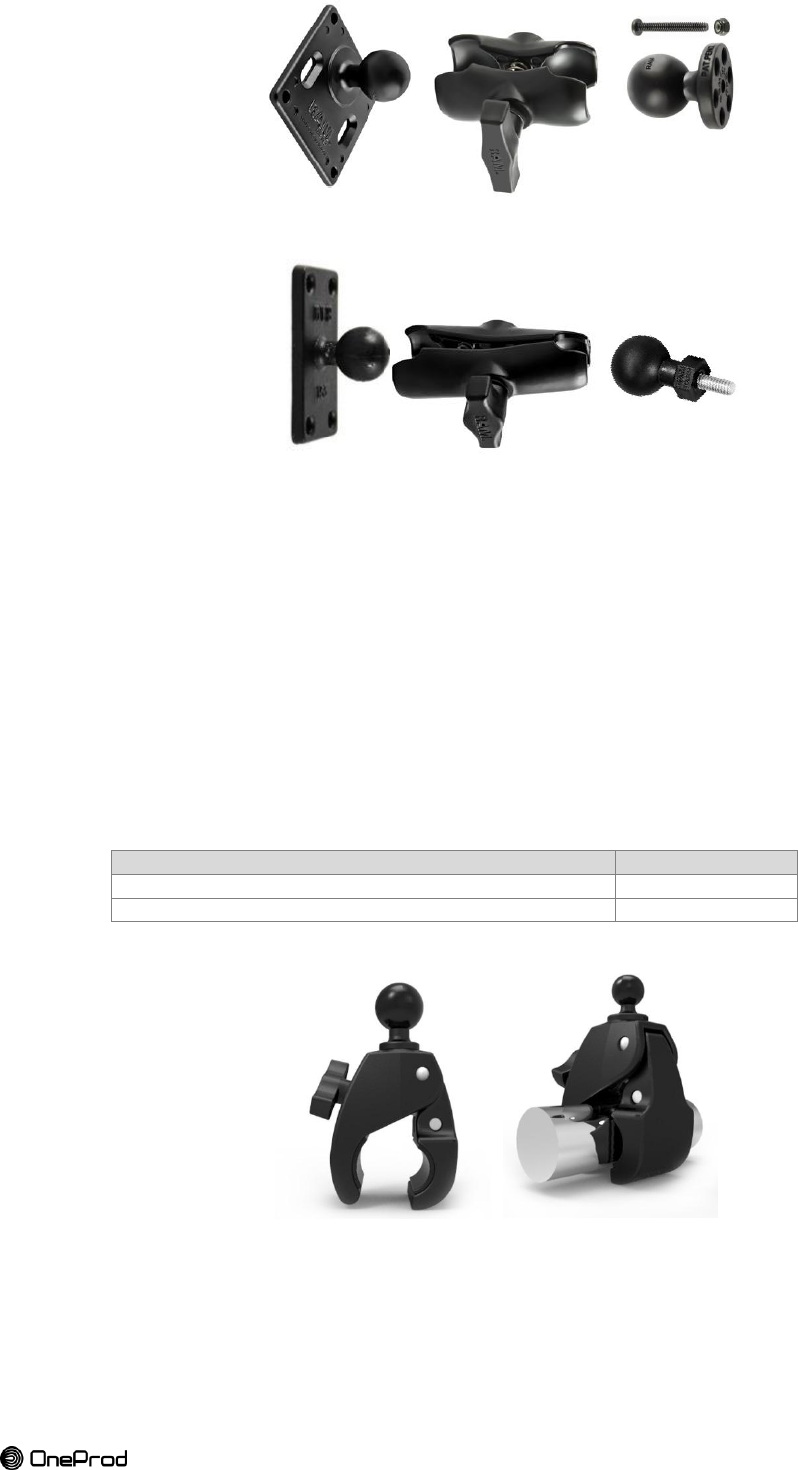
1.4.1.
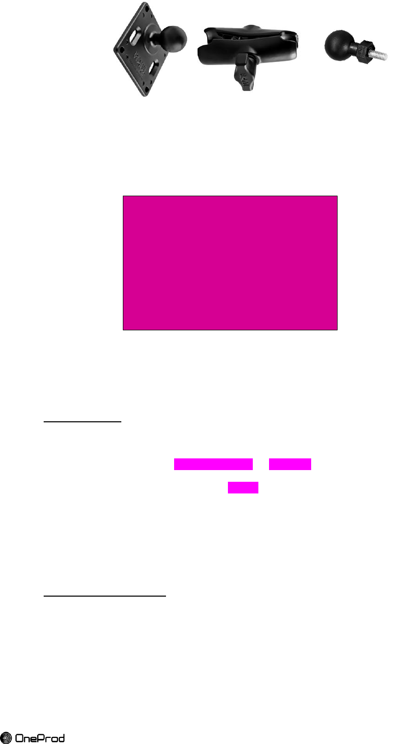
Mounting accessories for expander and gateway: RAM mounts
a. Fixed installation mounting accessories
The mounting accessories from RAM mounts supplied are limited to those mentioned below.
It should be noted that there are other types of compatible mounts. These options are not
available in the OneProd catalog.
Table 6: ball-joint mount references for expander mount (EGL1209000)
Description
Reference RAM
RAM 1" Tough-Ball™ with M6-1 x 6mm Male Threaded Post
RAP-B-379U-M616
RAM Double Socket Arm for 1" Ball Bases
RAM-B-201U
RAM 1.5" x 3" Rectangle Base with 1" Ball
RAM-B-202U-153
Table 7: ball-joint mount references for gateway mount (EGL1208000)
Description
Reference RAM
RAM Short Double Socket Arm for 1.5" Ball Bases
RAM-201U-B
RAM Topside Base with 1.5" Ball
RAP-395T-BCU
RAM 75mm x 75mm VESA 3.625" Plate with 1.5" Ball
RAM-2461U
Ensemble des accessoires
12
Brand of ACOEM
Figure 9: EGL1208000 ball-joint mount for gateway
Figure 10: EGL1209000 ball-joint mount for expander
b. Starter kit mounting accessories
The starter kit comes with tough-claw instead of Vesa plate or rectangle base
The RAM Tough-Claw™ is the perfect mounting base for quick and easy tool-less
installation and removal on round, square, odd shaped rails and bars. The Tough-Claw™
can be clamped on rails from 25.4 mm to 57.15 mm [1" to 2.25"] outer diameter.
Rubber pads provide stable, even gripping and protection of mounting surface. Clamp jaw is
configured for round, flat and odd shapes.
Clamping Range (Rail/Tube Surfaces): 25.4 mm to 57.15 mm [1" to 2.25"]
Clamping Range (Flat Surfaces): 0 to 55 mm [0" to 2.2"]
Physical Dimensions: Height: 167 mm [6.56"], Width: 57.15 mm [2.25"]
Material: High strength glass filled nylon construction with corrosion resistant stainless
steel hardware
Description
Reference RAM
RAM LARGE TOUGH-CLAW 1.5" DIAMETER BALL
RAP-401U
RAM LARGE TOUGH-CLAW 1" DIAMETER BALL
RAP-B-401U
Figure 11: RAM Tough-Claw™

13
Brand of ACOEM
1.4.2.
Batteries and O-ring seals
1.4.3.
Mounting tools
Les embases de fixations

14
Brand of ACOEM
Chapter 2
INSTALLATION GUIDE
15
Brand of ACOEM
1. SITE SURVEY
RF planning should be considered from the onset in order to determine the sensor locations
and options for the expanders and gateway installation.
In the vast majority of cases, the RF requirements do not impede the installation of the
sensors but by considering the RF implications from the start a very good first-time success
rate is achieved.
The typical link budget calculations that are used in radio planning are not valid in the vast
majority of industrial environments and accurate RF modelling is far too time consuming to
be practical.
For this reason, the RF planning is simply guided by empirical data gathered from a vast
array of previous installations. A set of best practices are presented which are effortless to
follow and delivers reliable performance without the need for calculations or sophisticated
survey equipment.
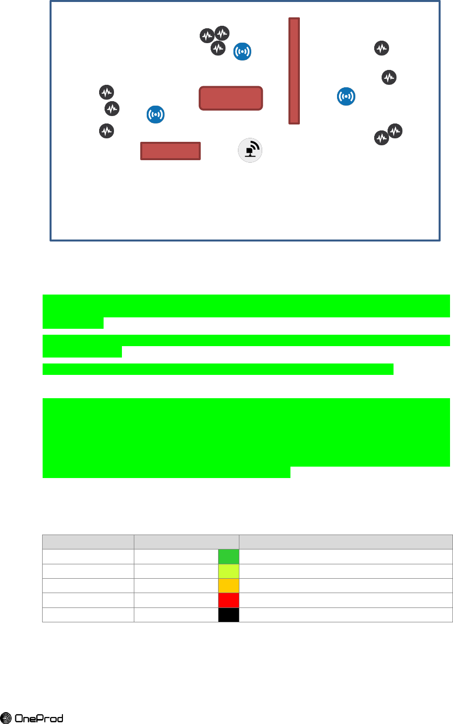
1.1. SITE PLANNING
The very first step is a site planning for RF (radio frequency).
On a site map:
Determine and identify the machines that require monitoring with Eagle sensors,
Determine potential locations for the gateway (allowing connection to the PoE <100m,
power connection <100m).
Estimate the distance from every Eagle sensor to the gateway after the initial survey and
use the table below to determine whether special precautions need to be taken.
Table 8 : distances for coverage quality
Environment
Simply Works!
Special Precaution
Dense metal structures with no line-of-sight
20m
50m
Sparse metal structures with limited line-of-sight
30m
100m
Line-of-sight
100m
400m
Identify obstacles that can interfere with radio coverage, sensors in complex areas
(limited space, metal shields) and the most distant sensors.
des schémas avec plusieurs implantations possibles
16
Brand of ACOEM
Figure 12: site survey example where all the information needed are identified
1.2. FIELD TEST
The second step is a field test to verify the reception of the farthest sensors or those with
doubts about their reception because of their situation (metallic surroundings, casing,
guards...) and
Perform a temporary installation in order to try out different gateway options and Eagle
sensors locations.
4. VERIFY THE PLAN WITH A TEMPORARY (OPTIONAL) INSTALLATION
When the planner is not confident due to inexperience or due to a particularly tricky
installation, it is warranted to perform a temporary installation in order to try out different
Gateway antenna options and Eagle Field Device locations. Typically the Eagles within the
“Just Works!” range are installed permanently from the onset. The remaining Eagles are
temporarily moved to the suspected troublesome locations and their signal strength
monitored using the gateway web application. It is common practice to immediately install
the Eagle permanently once the link quality is confirmed.
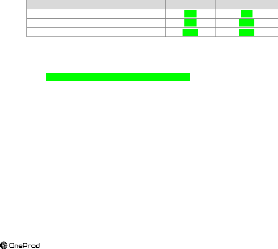
The signal strength of every device can be monitored from the web application of the
gateway. It is advisable to improve the signal strength for devices lower than -80dBm.
Table 9 : signal strength qualification
Signal strength
Quality
Action
-30 to -50 dBm
Excellent
-50 to -60 dBm
Good
-60 to -80 dBm
Fair
Can be improved using an expander
< -80 dBm
Poor
Must be improved using an expander
< -90 dBm
Out of coverage
Must be improved using an expander
ILLUSTRATION
SITE SURVEY

17
Brand of ACOEM
2. INSTALLATION PREREQUISITES
2.1. SAFETY
Refer to safety instructions, safety standards and procedures before installing any device.
2.2. SITE SURVEY
At this step the site survey is done.
The location of the gateway, sensors and expanders are identified in a site plan and ensure
to each sensor the appropriate radio coverage.
2.3. FASTENING SUPPORT
The gateway must be placed on a wall or a pole at a height of about 5m [16 ft].
Adequate mounting support has to be installed on site (such as mast) if necessary and can
therefore require the use of support facilities and operations of specific civil engineering if
needed for the configuration of the area.
2.4. NETWORK AND POWER
The gateway has to be powered and connected to the customer IP network
Prior to installation, the site must be equipped with both power and ethernet connections.
A technical cabinet can be necessary. The link to the customer IP network can be fiber-optic,
copper…
18
Brand of ACOEM
3. GATEWAY INSTALLATION
The gateway is fully assembled and ready to be deployed upon delivery.
Only one gateway is necessary to ensure the operation of the whole multi-hop wireless
infrastructure. Additional gateway may be necessary depending on
The gateway is linking the wireless network of Eagle devices (ISA100.11a) to an IP network
where the data are processed.
In hazardous environments, the operator has to arrange organizational safety measures
which reliably prevent the occurrence of an ignitable atmosphere, by default reduce the
probability that a flammable atmosphere can occur at all (employing the use of suitable gas
detection systems).
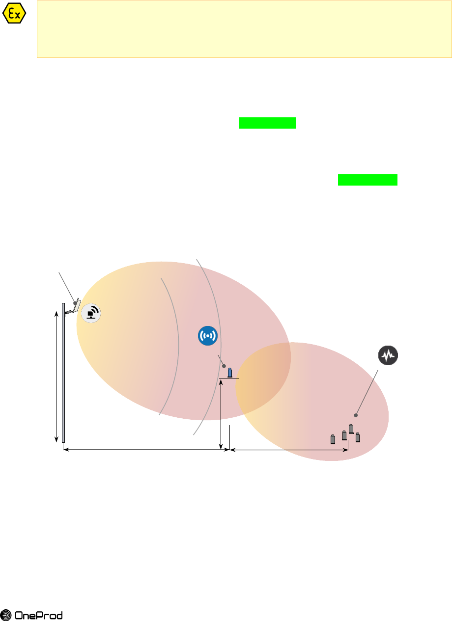
3.1. LOCATION
The location of the gateway is very important.
It must be placed at a height of about 5m [16 ft].
It must comply with a maximum radius of 100m [328 ft] radio coverage.
The housing face with OneProd logo indicates the embedded antenna location. This face
must be oriented in the direction of the sensors and expanders.
The radio link is sensible to physical obstacles, such as vehicles, tanks, or walls. If the
distance between the gateway and sensors or expanders exceed 100m [328 ft], it may be
necessary to add an additional expander to improve the signal strength.
Figure 13 : Eagle system overview
GATEWAY
100 m
50 m
EXPANDER
SENSORS
5 m
1 to 5 m
19
Brand of ACOEM
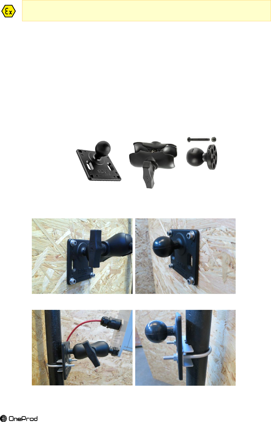
3.2. MOUNT
A damp cloth should be used when installing or taking off the gateway in hazardous areas to
eliminate static electricity resulting from this operation.
The gateway is fixed very quickly on a pole or on a wall using a ball-joint mount
(EGL1208000).
The ball-joint mount is constituted of:
A ball-joint head
Fixed on the bottom of the gateway using M8 screw and bolt.
A ball-joint base
The base is to be pegged on a wall or on a pole.
The mounting on a pole requires a clamp, nuts and washers.
The mounting on a wall is done using four screws and anchors.
The mounting on a structure requires bolts nuts and washers.
An arm
The arm is joining the two ball-joints allowing precise orientation of the gateway.
Figure 14: ball-joint base, arm and ball-joint head from RAM mounts (EGL1208000)
Figure 15 : mounting on a wall
Figure 16 : mounting on a pole (clamp detail)
20
Brand of ACOEM
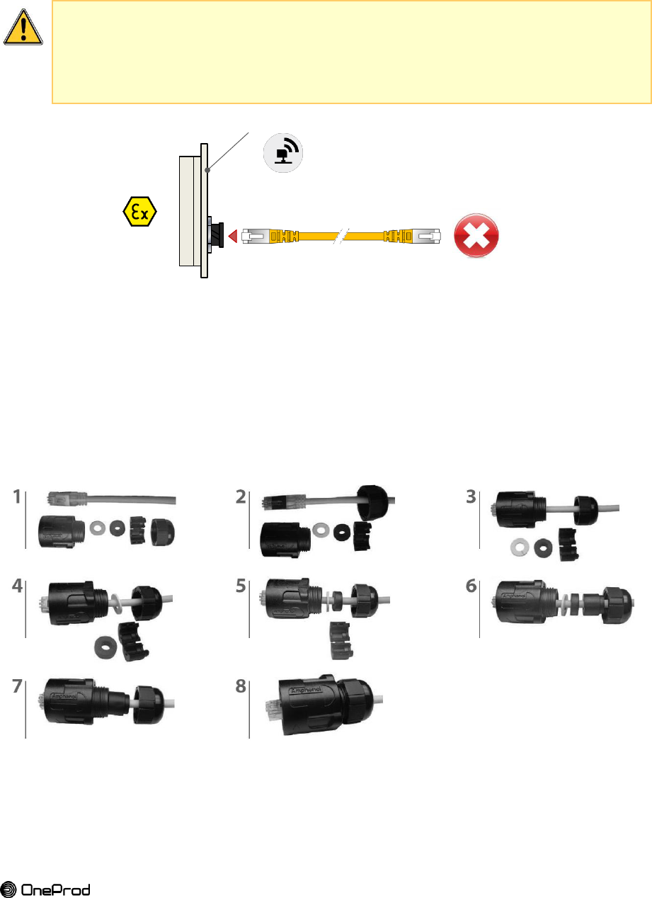
3.3. CONNECTION TO THE GATEWAY
The gateway is powered and connected to an IP network by a unique cable (ethernet
category 5e) thanks to a PoE (Power over Ethernet) injector (compliant with 802.11.3af-
2003).
Prior to installation, the site must be equipped with both power and ethernet connections
where the PoE will be installed. A technical cabinet can be necessary. The link to the
customer IP network can be fiber-optic, copper…
No hazardous on-field cabling!
The ethernet cable must not be connected to the other end.
The operator has to prevent the occurrence of an ignitable atmosphere (employing the
use of suitable gas detection systems).
Figure 17 . gateway connection
The Ethernet connection to the gateway is tool free.
Use a standard Ethernet Category 5e cable pulled from a technical cabinet (not Step 1. connected).
IP68 gland is delivered with the gateway housing and has to be mounted on the Step 2. Ethernet cable before connecting the gateway. Figure 18 describes this procedure.
Plug the assembly in the waterproof Ethernet receptacle located on the back of the Step 3. gateway.
Ensure that the assembly is fully tighten Step 4.
Figure 18 : Plug assembly instructions
GATEWAY
21
Brand of ACOEM
Figure 19 : cable, gland and connector assembled
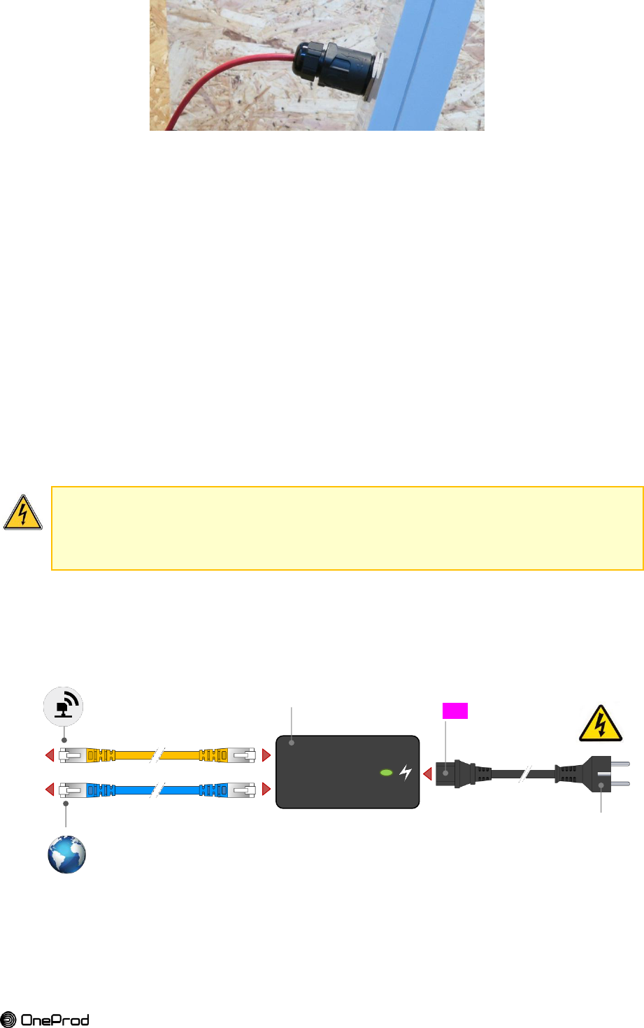
3.4. CONNECTION TO THE POE
Attention le POE doit être hors zone ATEX.
The PoE is preferably located close to the gateway (sauf en zone ATEX)but can be located
at 100m max (Ethernet limitations).
Manage cables by using different colors to differentiate PoE from LAN.
Define a standard that is relevant to your requirements or the one in application in your
company.
Blue or Grey for Network (LAN)
Yellow or Red for PoE
Be careful when connecting.
Check twice that “PoE” port is connected with the gateway.
Wrong connections may cause damages
Connect the ethernet cable from the gateway to the PoE injector on the "PoE" Port. Step 1. Connect "LAN" port of the PoE to the IP network. Step 2. Check your connections Step 3. Power the PoE using the appropriate power plug for your country. Step 4.
Figure 20 : PoE connection instructions
PoE (LAN+DC)
LAN
GATEWAY
IP NETWORK
POWER
110-240 V
50-60 Hz
C13
48 V - 0.5 A
22
Brand of ACOEM
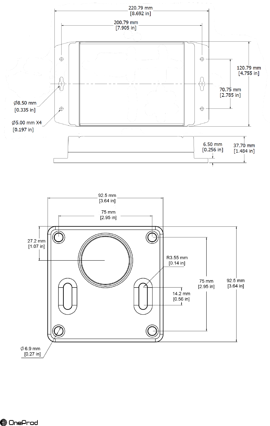
3.5. SIZES
Figure 21 : dimensions of the gateway
Figure 22 : dimensions of the ball-joint base RAM-2461U
23
Brand of ACOEM
4. SENSORS INSTALLATION
4.1. SENSOR LOCATION
The sensors are mounted on the equipment to monitor following the rules for vibration
sensor installation.
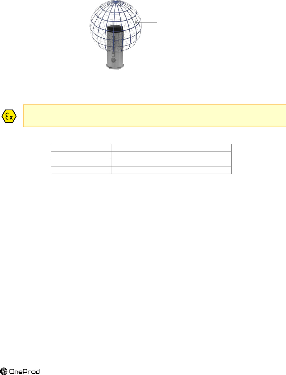
Leave enough space around the sensor to ensure the best transmission/reception possible
of radio signals. At least 100 mm around the device antenna (plastic cap). If the sensor has
to be installed in tiny spaces, the use of an expander might be a solution to improve the radio
coverage (if necessary).
Figure 23 : clear space around the sensor/expander
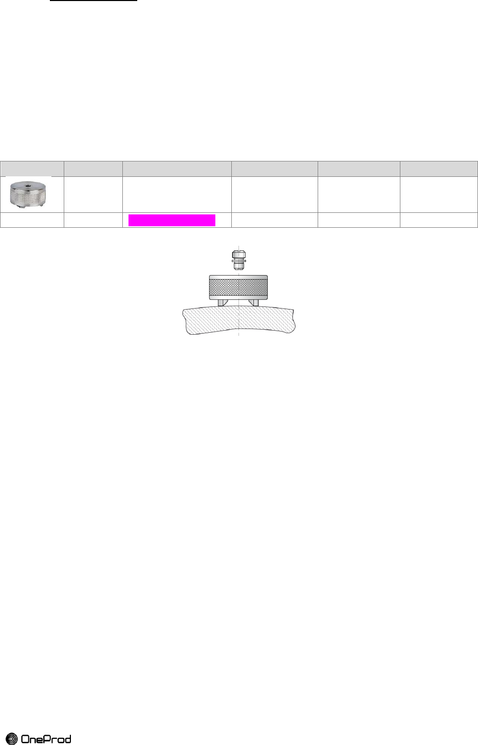
4.2. MOUNTING INFORMATION FOR SENSORS
A damp cloth should be used when installing or taking off the gateway in hazardous areas to
eliminate static electricity resulting from this operation.
Table 10 : mounting characteristics for sensors
Thread
M6-1, max depth 6mm [0.23 in]
Flat mounting surface
Ø32.5 mm x 1mm height [Ø1.28 in x 0.039 in]
Hex head
44 mm [1.73 in]
Fastening torque
5 – 7 Nm [44 – 62 inch-lb]
CAUTION:
Do not grasp the sensor by the plastic cap.
Do not hit the plastic cap.
Do not tighten the sensor by the plastic cap
5 mounting modes:
Direct mounting: M6 stud on a flat surface
Spotface mounting : for convex surface
Cementing pad: the easiest way to install
Triaxial mount: to position the triaxial sensor accurately.
Temporary mount: only for testing wireless coverage before final assembly.
Ø100 mm
clear space
24
Brand of ACOEM
Figure 24: sensor and expander mounting interface (threads, hex head)
Flat mounting surface
Ø32.5 mm x 1mm height
[Ø1.28 in x 0.039 in]
M6-1, 6 mm
[M6-1, 0.23 in]
AMELIORER
DESSIN
Hex head 44 mm
[1.73 in]
25
Brand of ACOEM
4.2.1.
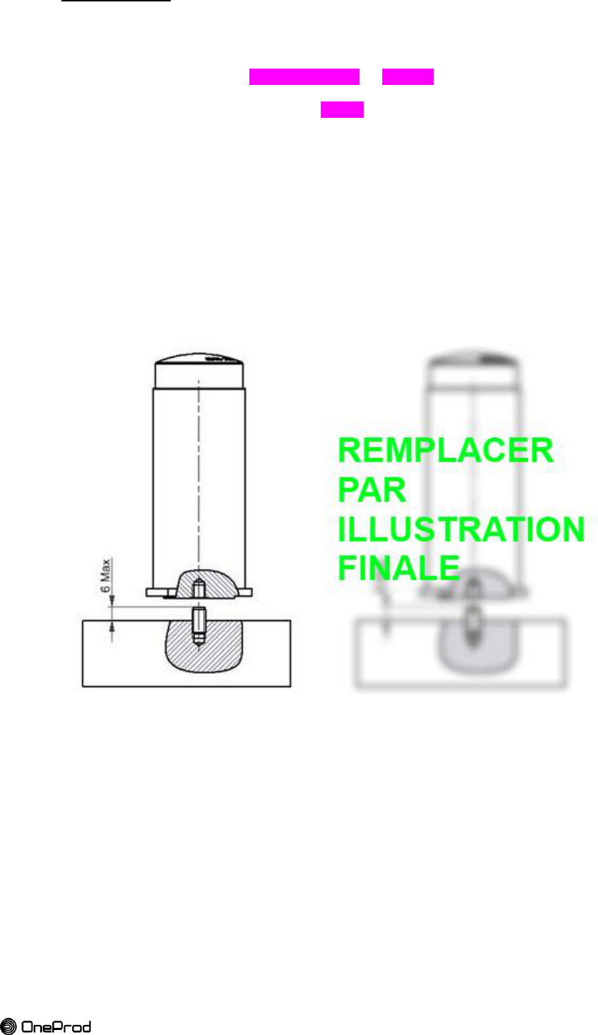
Direct mounting
See Figure 25
Ensure a flat surface: remove paint layers. Step 1. NOTE: if you use a spot facing tool be sure to not exceed 0.8mm depth [0.031 in].
Drill a hole (Ø5 mm and XXmm depth [Ø 0.19 in - ) Step 2. Thread the hole with M6 tap Step 3. Screw M6 stud with a length of XXmm Step 4. CAUTION: The part of the stud inserted into the sensor can be up to 6 mm
[0.23 in]. A bottoming stud may cause base-strain and also potentially damage
electronics.
Screw the sensor on the stud and tighten at 5 - 7 Nm [44 - 62 inch-lb] using the Step 5. dedicated tube wrench and your handgrip.
NOTE: for a better contact a film of grease/oil can be applied between sensor and
mounting surface (note the oil/grease must be compatible with the temperature of
the measurement point).
CAUTION: If you use a 44mm wrench [1.73 in] or an adjustable wrench be careful
to observe the indicated torque range.
Fill in the installation report with sensor information (S/N, type, location, Step 6. orientation…)
Figure 25: direct mounting with M6 stud
Figure 26: spotface mounting
26
Brand of ACOEM
4.2.2.
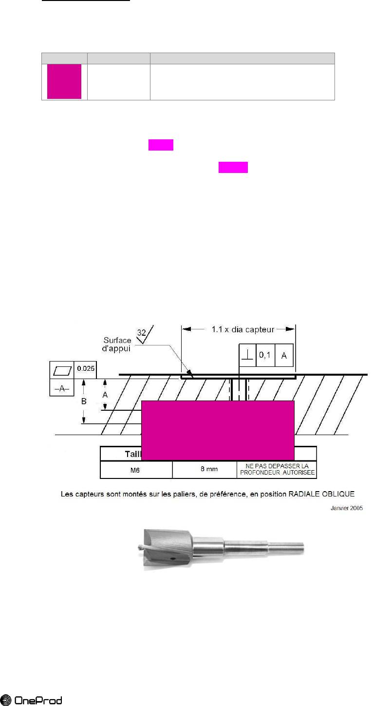
Spotface mounting
See Figure 26
This mounting mode is mainly dedicated to convex surfaces or to remove paint layers on a
machine.
Picture
Reference
Description
ACA1030000
Washer adapter for 1"1/4 spotface + M6 stud
Create a flat surface on the machine using a 1.25” [31.75 mm] spot facing tool with Step 1. a drill bit for an M6 tap
Do not exceed 2 mm depth.
Thread the hole with M6 tap Step 2. Screw M6 stud with a length of XXmm
Step 3. CAUTION: The part of the stud inserted into the sensor can be up to 6 mm. A
bottoming stud may cause base-strain and also potentially damage electronics.
Thread the washer adapter on the stud. This washer is necessary to adapt the Step 4. 1.25” spotface depth and diameter to the sensor design.
Screw the sensor on the stud and tighten at 5 - 7 Nm [44 - 62 inch-lb] using the Step 5. dedicated tube wrench and your handgrip.
NOTE: for a better contact a film of grease/oil can be applied between sensor and
mounting surface (note the oil/grease must be compatible with the temperature of
the measurement point).
CAUTION: If you use a 44 wrench or an adjustable wrench be careful to observe
the indicated torque range.
Fill in the installation report with sensor information (S/N, type, location, Step 6. orientation…)
Figure 27: spotfacing tool with drill bit
TRADUIRE
COIMPLETER
27
Brand of ACOEM
4.2.3.
Cementing pad mounting
This mounting mode is fast and easy.
Picture
Reference
Description
ACA1023000
M6 cementing pad - Ø35 mm [1.38 in]
Recommended adhesives:
HBM® X60: is a 2-component fast curing adhesive, consisting of a liquid component and
a powder.
LOCTITE® F246™: is a one component, toughened and high strength acrylic adhesive
system for structural bonding.
Remove coats of paint to get a clean metallic surface on the machine Step 1. Remove grease from the surface Step 2. Glue the cementing pad using HBM® X60 or LOCTITE® F246™ adhesive. Pin the Step 3. pad to the surface.
WARNING: Refer to gluing safety datasheet and procedures before gluing and
always wear the prescribed protections.
Wait for the glue to dry Step 4. Screw the sensor on the cementing pad and tighten at 5 - 7 Nm [44 - 62 inch-lb] Step 5. using the dedicated tube wrench and your handgrip.
NOTE: for a better contact a film of grease/oil can be applied between sensor and
cementing pad (note the oil/grease must be compatible with the temperature of
the measurement point).
CAUTION: If you use a 44 wrench or an adjustable wrench be careful to observe
the indicated torque range.
Fill in the installation report with sensor information (S/N, type, location,
Step 6. orientation…)
Figure 28 : cementing pad mounting
28
Brand of ACOEM
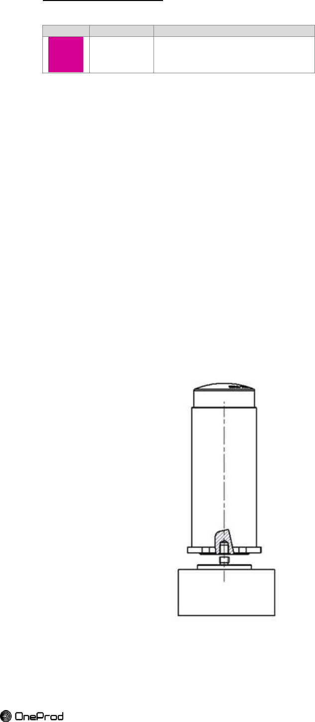
4.2.4.
Triaxial mount
This mounting mode is dedicated to triaxial sensors. It helps to
Picture
Reference
Description
ACA1029000
Specific fastening for triaxial sensors (washer and stud)
Ensure a flat surface: remove paint layers. Step 1. NOTE: if you use a spot facing tool be sure to not exceed 2 mm depth [0.078 inch]. Step 2. Create a flat surface on the machine using a 1.25” spot facing tool with a drill bit for
an M8 tap
Do not exceed XX mm depth.
Drill a hole (Ø6.8 mm and XXmm depth [Ø 0.28 in – XX in) Step 3. Thread the hole with M8 tap Step 4. Screw special M8 stud in the machine Step 5. Thread the washer on the stud. This washer is necessary to adapt the 1.25’’ Step 6. spotface depth and diameter to the sensor design.
Screw the sensor on the M6 side of the stud until contact without tightening it. Step 7. Identify orientation of the triaxial sensor axis. Step 8. Turn the washer to adjust the axis orientation in the chosen direction Step 9. Use the dedicated tool for orientation if the dedicated tube wrench is also used.
Screw the sensor on the stud and tighten at 5 - 7 Nm [44 - 62 inch-lb] using the Step 10. dedicated tube wrench and your handgrip.
NOTE: for a better contact a film of grease/oil can be applied between mounting
surfaces (note the oil/grease must be compatible with the temperature of
the measurement point).
CAUTION: If you use a 44 wrench or an adjustable wrench be careful to observe
the indicated torque range.
Fill in the installation report with sensor information (S/N, type, location, Step 11. orientation…)
Figure 29 : specific fastening for triaxial sensors
29
Brand of ACOEM
4.2.5.
Temporary mount
Performing field test during a site survey may require a temporary mount. This allows testing
locations and orientations of the farthest sensors or those with doubts about their reception
because of their situation (metallic surroundings, casing, guards…) to get the best coverage
possible.
A magnetic mount is the best solution in that specific case.
Screw the sensor on the magnetic base using appropriated stud or bolt (M6). Step 1. Place the system on the location to test Step 2.
NOTE: An adapter stud may be required depending on the design of the magnetic base to
allow M6 mount.
Table 11: magnetic mounts references
Brand
Reference
Adapter stud
Pull strength
Max temp.
CTC
MH114-3A +
MH108-5B
1/4-28 to M6-1
23kg [50lbs]
80°C [176°F]
OneProd
ACA To be defined
N/A
23kg [50lbs]
80°C [176°F]
Figure 30 : multi-purpose magnetic base
30
Brand of ACOEM
5. EXPANDER INSTALLATION
5.1. EXPANDER LOCATION
The location of the expanders is very important. It must comply with a maximum radius of
50m radio coverage. It must be located in the coverage of the gateway or of another
expander.
It is best practice to install the expanders at high to improve the coverage. This way the
expander has a clear view of the sensors close to it.
The blue plastic cap is where the embedded antenna is located. It must be oriented in the
direction of the sensors or at least vertically.
The radio link is sensible to physical obstacles, such as vehicles, tanks, or walls. If the
distance between an expander and sensors exceed 50m or an obstacle is present, it may be
necessary to add an additional expander to improve the signal strength.
5.2. EXPANDER MOUNTING
A damp cloth should be used when installing or taking off the gateway in hazardous areas to
eliminate static electricity resulting from this operation.
Expander shares the same design as sensors. See “Figure 24: sensor and expander
mounting interface (threads, hex head)” on page 31.
Table 12: mounting characteristics for expander (identical to sensor)
Thread
M6-1, max depth 6mm [0.236 in]
Flat mounting surface
Ø32.5 mm x 1mm height [Ø1.28 in x 0.039 in]
Hex head
44 mm [1.73 in]
Fastening torque
5 - 7 Nm [44 - 62 inch-lb]
CAUTION:
Do not grasp the expander by the plastic cap.
Do not hit the plastic cap.
Do not tighten the expander by the plastic cap
4 mounting modes:
Ball-joint mount : the most appropriate mounting allowing precise orientation
Direct mounting: M6 stud on a flat surface
Cementing pad: the easiest way to install
Temporary mount: only for testing wireless coverage before final assembly.
5.2.1.
Ball-joint mount
The expander is fixed very quickly on a pole or on a wall using a ball-joint mount.
The ball-joint mount is constituted of:
A ball-joint head
Screw the expander on M6-1 x 6MM male threaded post of the ball-joint head.
A ball-joint base
The base is to be pegged on a wall or on a pole.
The mounting on a pole requires a clamp, nuts and washers.
The mounting on a wall is done using four screws and anchors.
The mounting on a structure requires bolts nuts and washers.
An arm
The arm is joining the two ball-joints allowing precise orientation of the expander.
31
Brand of ACOEM
Figure 31: ball-joint base, arm, and ball-joint head for expander mount
Figure 32 : ball-joint mount installation
5.2.2.
Direct mounting
See « Figure 25: direct mounting with M6 stud » on page 32
No need of flat surface Step 3. Drill a hole (Ø5mm and XXmm depth [Ø 13/64 in - ) Step 4. Thread the hole with M6 tap Step 5. Screw M6 stud with a length of XXmm Step 6. CAUTION: The part of the stud inserted into the expander can be up to 6 mm. A
bottoming stud may cause base-strain and also potentially damage electronics.
Screw the sensor on the stud and tighten at 5 - 7 Nm using the dedicated tube Step 7. wrench and your handgrip.
CAUTION: If you use a 44 wrench or an adjustable wrench be careful to observe
the indicated torque range.
Fill in the installation report with expander information (S/N, location,…) Step 8.
5.2.3.
Cementing pad mounting
See Chapter 3 § 0 «
ILLUSTRATIONS
montage BALL-
JOINT RAM MOUNT
POUR EXPANDER

32
Brand of ACOEM
Cementing pad mounting » on page 34
5.2.4.
Temporary mount
A Tough-Claw™ is the perfect mounting base for quick and easy tool-less installation
and removal on round, square, odd shaped rails and bars. The Tough-Claw™ can be
clamped on rails from 25.4 mm to 57.15 mm [1" to 2.25"] outer diameter. See Chapter 2
§ 1.4.1 b “Starter kit mounting accessories” on page 19.
A magnetic base can also be used: See Chapter 3 § 4.2.5 « Temporary mount » on page
31
33
Brand of ACOEM
6. BATTERY REPLACEMENT (SENSORS / EXPANDER)
Refer to Safety Instruction § 0
Standards applied:
EN60079-0 edition 2012
Atmosphères explosives Partie 0 : Matériel - Exigences générales
EN60079-11 edition 2012
Atmosphères explosives Partie 11: Protection de l’équipement par sécurité intrinsèque «i»
IEC 60079-0 : 2011 Edition: 6.0
Explosive atmospheres - Part 0: General requirements
IEC 60079-11 : 2011 Edition: 6.0
Explosive atmospheres - Part 11: Equipment protection by intrinsic safety "i"
Special condition for a safe use:
- -20°C ≤ Tamb ≤+85°C
- WARNING – USE ONLY SAFT LS33600 BATTERY. Only replace the primary cell in a
safe area
- The equipment must be installed so that it is protected against mechanical shocks.
- A damp cloth should be used when installing or taking off the sensors and expanders
in all hazardous areas to eliminate static electricity resulting from this operation.
Primary cell on page 9 before any battery replacement.
Only use SAFT LS33600 3.6 V primary lithium-thionyl chloride (Li-SOCl2)
D-size bobbin cell
Use of any other battery causes risk of explosion
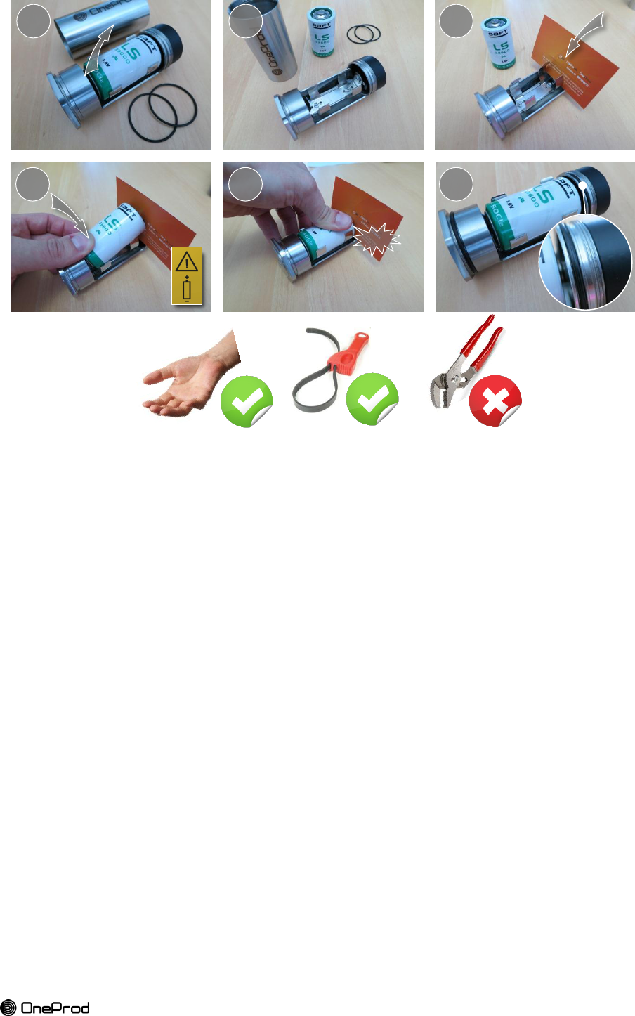
Respect the orientation of the battery. A Mistake may result in short circuit of the cell.
Step 1. Open the sensor by unscrewing the protection tube. If the tube is hard to unscrew,
use a rubber strap wrench. Remove the old battery from the bottom side. Pull out
the seals (pinch up it to grab it).
Step 2. Prepare a new battery and 2 new seals. Use only primary cell SAFT LS33600 3.6
V lithium-thionyl chloride (Li-SOCl2) and O-ring seal NBR 70 SH Øint. 37.82mm [1
31/64 in] x Øtorus 1.78mm [1/16 in], UL MH25709 certified.
Step 3. Use a cardboard (business card) to help the battery to slip in place and avoid short
circuit.
Step 4. Start to insert the battery from the bottom. The battery must be installed in the
direction indicated by the polarity symbol.
Step 5. Push the top part to fully insert the battery in its housing.
Step 6. Place the new seals in the appropriate groove. Check that the battery is well
inserted and manually close the sensor with the protection tube.
34
Brand of ACOEM
CAUTION: Only use your hands or a rubber strap wrench to remove the protection tube from
the sensor/expander. The use of tongue-and-groove pliers (also known as water pump
pliers, adjustable pliers, groove-joint pliers, arc-joint pliers, Multi-Grips, and Channellocks)
are forbidden and will cause damages and lose of sealing IP67.
7. PROTECTIONS
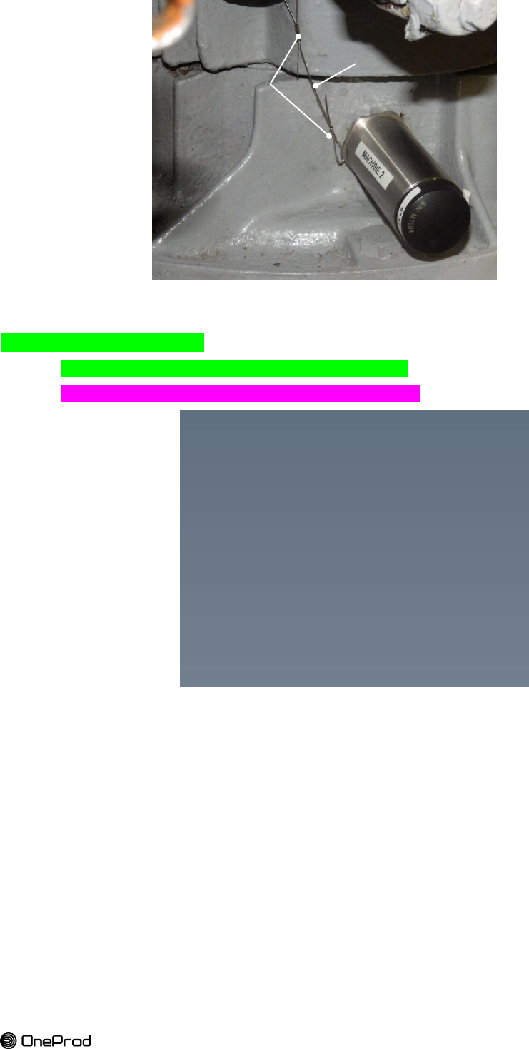
7.1. FALL PROTECTION
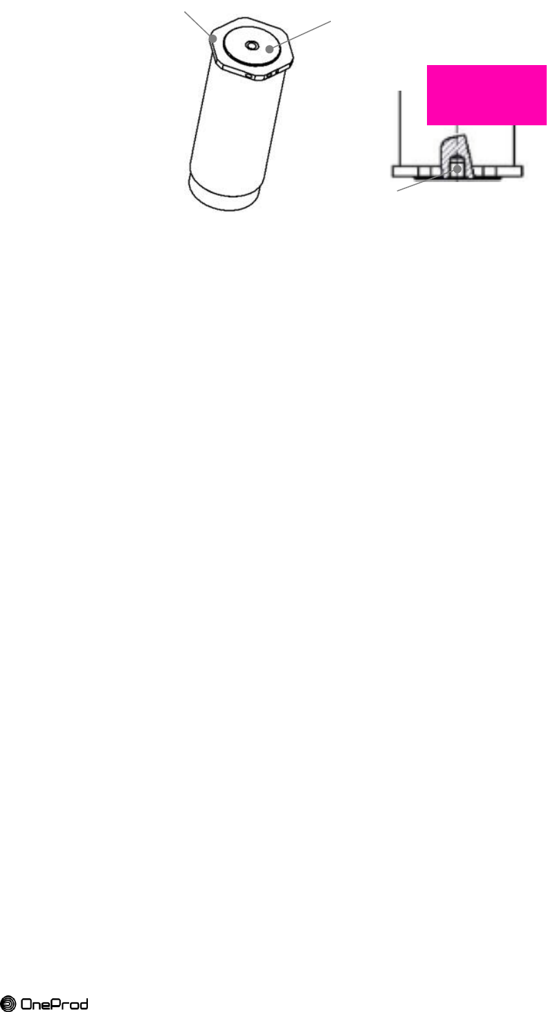
Make a sensor/expander tether with a stainless steel lanyard to provide more safety and
avoid to the sensor/expander to fall.
Step 1. Thread a thin cable through the Ø 2 mm hole [Ø 0.078 in] drilled into the
sensor/expander.
Thread the other side of the wire through a fixed object Step 2. Crimp the loop ends Step 3.
1
2
3
6
4
5
CLIP
35
Brand of ACOEM
7.2. PROTECTIVE SHIELD
You can use a footstep protection to protect the sensor
Need of drawing for dimensions and steps for installation
Figure 33: protective shield accessory
Ø1mm wire
Crimp

36
Brand of ACOEM
STOP – STOP - STOP – STOP - STOP – STOP - STOP – STOP -
DOCUMENT EN COURS
D’ELABORATION
LES PARAGRAPHES CI-DESSOUS
NE SONT PAS A JOUR

37
Brand of ACOEM
Chapter 3
OPERATING MANUAL

38
1. USAGE
1.1. POWER UP THE SENSOR AND EXPANDER
To power the Eagle Field Device for the first time, unscrew the battery and remove the
protective tape on the battery's connectors. Then screw the battery fully
1.1.1.
Sleep mode
After power-up the Eagle field device will attempt to join the ISA100.11a network every 5
minutes while entering in an ultra-low power state between the join attempts. After 30
minutes the join attempt period will increase to 15 minutes for the subsequent 24 hours
followed by one join attempt per hour.
To exit sleep mode unscrew and screw the battery fully (off/on).
2. EAGLE EMBEDDED PROCESSING
2.1. PARAMETERS
2.1.1.
Overall velocity
Table 13: overall velocity parameter settings for Eagle sensor
Paramètre mesuré
Vitesse vibratoire
Unité résultat
mm/s
inch/s
Référence dB
Not used
Type entrée
Accéléromètre
Unité entrée
g
Sensibilité (mV/unité entrée)
Not used
Pleine échelle (unité param)
Not used
Autorange
YES (fixed)
Intégration
1 intégration
Surveillance temps réel
Not used
Constante de temps
Not used
Filtre passe haut
2 Hz
10 Hz
Filtre passe bas
sans
1 kHz
Détection
RMS
Durée
5s (fixed)
Moyennage
Average (fixed)
2.1.2.
Overall acceleration
Table 14: overall acceleration parameter settings for Eagle sensor
Paramètre mesuré
Accélération
Unité résultat
g
Référence dB
Not used
Type entrée
Accéléromètre
Unité entrée
g
Sensibilité (mV/unité entrée)
Not used
Pleine échelle (unité param)
Not used
Autorange
Oui
Intégration
0 intégration
Surveillance temps réel
Not used
Constante de temps
Not used

39
Brand of ACOEM
Filtre passe haut
sans
2 Hz
Filtre passe bas
sans
20 kHz
Détection
RMS
Durée
0.1 to 5s max
Moyennage
Average
2.1.3.
Temperature
Table 15: temperature parameter settings for Eagle sensor
Paramètre mesuré
Température
Unité résultat
°C
°F
Référence dB
Not used
Type entrée
Continue
Unité entrée
Not used
Sensibilité (mV/unité entrée)
Not used
Pleine échelle (unité param)
Not used
Not used
Not used
Intégration
0 intégration
Surveillance temps réel
Not used
Constante de temps
Not used
Filtre passe haut
Sans
Filtre passe bas
Sans
Détection
Pas de détection
Durée
To be defined
Moyennage
Moyenne

40
2.2. SIGNALS
2.2.1.
Spectrum
Table 16: spectrum setting parameters for Eagle sensor
Paramètre mesuré
Accélération
Vitesse
Unité résultat
g (Accélération)
mm/s (Vitesse)
in/s (Vitesse)
Référence dB
Not used
Type entrée
Accéléromètre
Unité entrée
g
Sensibilité (mV/unité entrée)
Not used
Pleine échelle (unité param)
Not used
Autorange
Oui
Non
Filtre passe haut
Sans
2 Hz
Intégration
0 (Accélération)
1 (Vitesse)
Fréquence. Maximale (Hz)
100
200
500
1,000
2,000
5,000
10,000
20,000
Nombre de points de FFT
800
1,600
3,200
Fenêtre
Hanning
Mode de moyennage
Linéaire
Nombre de moyennes
5 (changeable)
Recouvrement
0 %
50 %
75 %
Déclenchement
Libre
Niveau déclenchement (unité entrée)
Not used
Délai de déclenchement (ms)
Not used
Pente
Not used
Hystérésis (unité entrée)
Not used

41
Brand of ACOEM
2.2.2.
Time signal
Table 17: time signal setting parameters for Eagle sensor
Paramètre mesuré
Acceleration
Unité résultat
g
Type entrée
Accelerometer
Unité entrée
g
Sensibilité (mV/unité entrée)
Not used
Pleine échelle (unité param)
Not used
Autorange
YES (Fixed)
Filtre passe haut
Sans
2 Hz
Intégration
0 intégration
Fréq. Echantillonnage (Hz)
256
512
1,280
2,560
5,120
12,800
25,600
51,200
Nombre de point du signal
512
1,024
2,048
4,096
8,192
16,384
Mode de moyennage
Linéaire
Nombre de moyennes
1
Recouvrement
Not used
Déclenchement
Libre
Niveau déclenchement (unité entrée)
Not used
Délai de déclenchement (ms)
Not used
Pente
Not used
Hystérésis (unité entrée)
Not used
Analyse synchrone
Not used
Détection enveloppe
Not used
Facteur Zoom/Env
Not used
Fréquence centrale Zoom/Env
Not used

42
Chapter 4
OLD EAGLE
Chapitre à supprimer => pas de confusion dans les
produits ATEX. Mettre cet article dans un autre document
(note d'application par exemple)
1.1. PROTECTIONS
1.1.1.
Lightning protection
Protection of RF connections
It is recommended to protect the connections to prevent a long-term oxidation,
oxidation for which RF connections are more sensitive than others. Adhesive tape
used is self-amalgamating types (Scotch® Super 33+ 3M™).
1.2. NETWORK CONNECTION
The gateway is powered and connected to the network with a unique ethernet cable through
a PoE injector (power over ethernet).
PoE injector characteristics:
Input: 110-240V ~ 50-60Hz
Output: 24V DC – 1A
Connect the LAN port on the injector directly to a computer or Ethernet switch through an
Ethernet cable.
Unscrew the gland from the Gateway and connect the POE port (POE OUT) on the
injector directly to the gateway through an ethernet cable.
Power the PoE injector.
The gateway initialize (1-2 minutes)
The max ethernet cable length is 100 m for each cable.
RJ45
Ethernet category 5 cable
Max length = 100 meter / cable
50 sensors / gateway max.
43
Brand of ACOEM
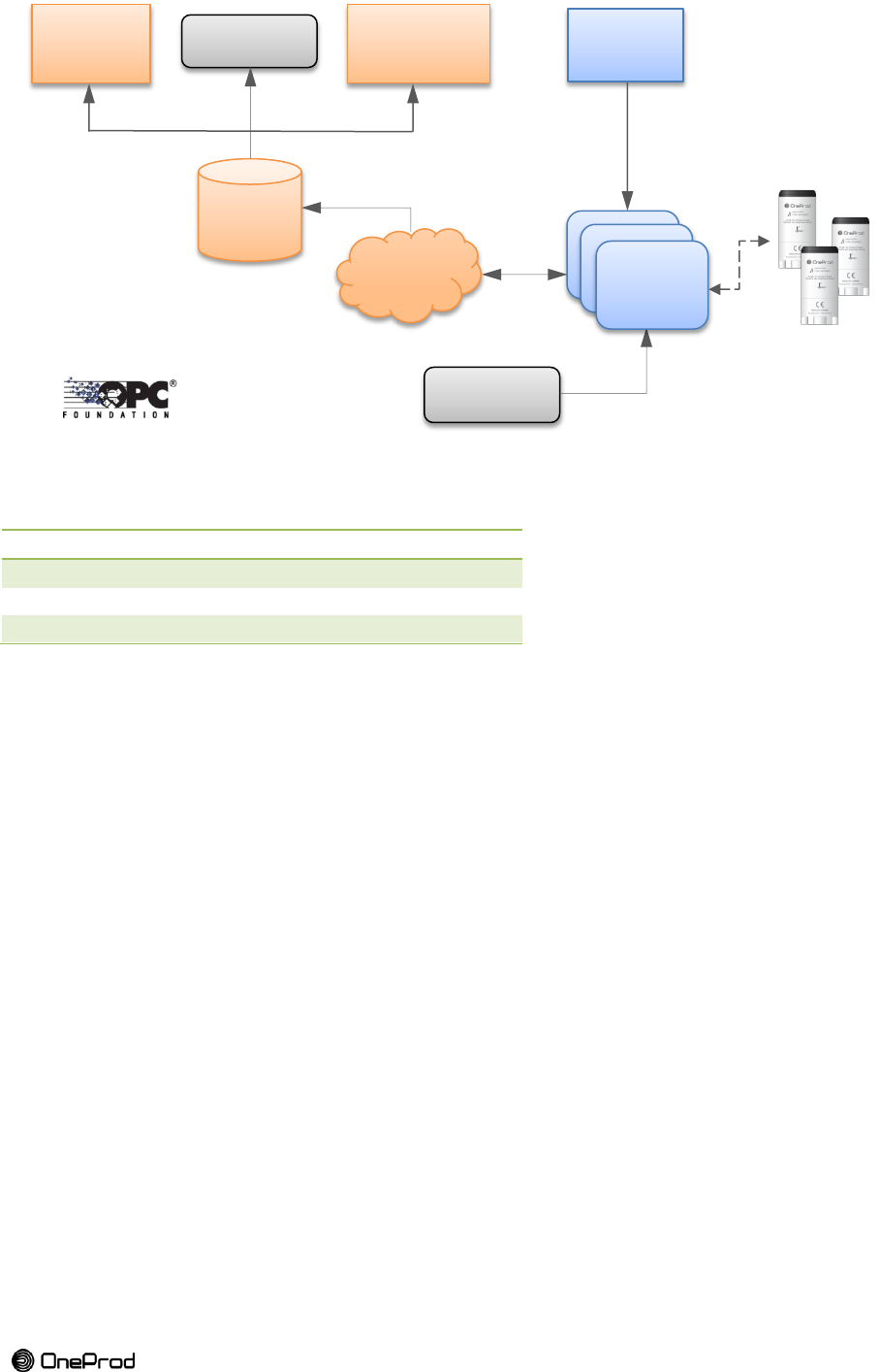
2. NETWORK ARCHITECTURE
IP address
Port
192.168.0.yyy
80
Gateway web interface
192.168.0.yyy
23
Telnet
192.168.0.yyy
4900
Gateway API
The computer IP address has to be in the same subnet as the Gateway
Example:
Gateway: 192.168.0.110
Computer: 192.168.0.100
Eagle
Driver
NEST
Database
Gateway
OPC Servers
TCP protocol
ISA-100 .11a protocol
Gateway
EAGLE
Gateway
Web
browser
Oneprod
NEST
OPC clients
NEST
(software)

44
Chapter 5
COMMON USAGE OF EAGLE
Eagle is designed to make measurements
daily while using the battery for several years
without the need of dismantling.
ENERGY SAVING IS A KEY INPUT
1. CONFIGURATION
Eagle is ready for embedded processing, but
for the moment Eagle’s firmware is capable of
measuring time signals which can be post processed in XPR.
1.1. TIME SIGNAL
To perform a diagnostic we recommend the following signals
Signal
Sampling
frequency (Hz)
Nbr. of
points
Type
T-512Hz-4k
512
4096
WAV LF
T-5.12kHz-16k
5120
16384
WAV MF
T-51.2kHz-16k
51200
16384
WAV HF
1.2. FFT
FFT can be processed in XPR based on the signal above. A new FFT post-processing was
developed in XPR. Its name is “Spectrum”. It needs only to define the signal to process and
the number of lines of the FFT. Spectrum is a FFT with Hanning window / 75% overlap /
Unilateral amplitude.
Name
Signal to process
Nbr. of
lines
FFT range (Hz)
Corresponding
# of average
FFT LF
T-512Hz-4k
800
0-200
5
FFT MF
T-5.12kHz-16k
1600
0-2000
10
FFT HF
T-51.2kHz-16k
800
0-20000
20
1.3. PARAMETERS
You can use all the parameters that XPR can post-process to configure your defect detection
grid.
XPR gives you the possibility to set thresholds for your parameters.
Refer to XPR user manual.
Battery life
Network
performance
Signals for
diagnostic
Figure 30: find the right balance

45
Brand of ACOEM
2. PERIODICITY
Normal use of the product corresponds to a daily measurement and no more than 6
measurements per day.
Below 4h of periodicity (minimum theoretical periodicity is 10 minutes) many parameters can
affect periodicity and battery life.
The numbers of sensors of one network (paired with the same gateway) is a parameter. The
more they are, the larger is the minimum periodicity. This is due to the sum of time needed
for each sensor to send its data.
The signal strength is another parameter. The weakest the signal, the longer the upload.
3. AUTONOMY
The expected autonomy when measuring the recommended configuration is:
Periodicity
Uniaxial
Triaxial
8-24 hrs
> 5 years
~ 5 years
6 hrs
> 5 years
~ 3 years
4 hrs
~ 4 years
~ 1 year
Things that will make this Autonomy worse:
RF link: poor RF link will cause large transfer duration or the signal to fail to transmit and
retry, which uses up power.
Temperature: Extreme temperatures makes the electronics use more power and the
battery to have less potential capacity.
Signals: aggressive waveforms configurations or high quantity of signals make data
bigger and increase the transfer duration.
Periodicity: too short periodicity increases the number of measurement requests and
transfers.
All this points are interconnected; the goal is to find the appropriate balance.
0:00
0:30
1:00
1:30
2:00
2:30
3:00
3:30
4:00
4:30
010 20 30 40 50
Minimum periodicity (h)
Number of sensors / gateway
Impact of sensors on periodicity
TRIAXIAL
UNIAXIAL

46
Chapter 6
GATEWAY WEB INTERFACE
The gateway web interface allows to change multiple settings and to monitor signal strength.
1. CONNECT TO THE GATEWAY INTERFACE
Force your computer IP address to the same subnet as the Gateway (ex.:
192.168.0.100) and test whether it responds to pings.
The Gateway has two IP addresses. The configurable and failsafe address
172.17.17.17.
Connect to the web-interface at http://< IP address> (ex. : 192.168.0.112) and log into its
Monitoring and Control Portal with the username and the password provided on the
Factory Settings Report received with the delivery.
The Network / Devices page will display the connected hardware.
The Gateway incorporates 3 ISA100.11a components namely the System Manager,
Backbone Router and Gateway. All three should be present in the Devices list.
The paired and powered field devices should appear in that list.
2. MONITOR SIGNAL STRENGTH
After the Eagle has joined, the Gateway Backbone will start recording the received signal
strength from every device.
Click on the Backbone’s EUI-64 address on the Network / Devices page and then on the
Neighbours Health tab. Click Refresh.
A list of Eagle Field Devices together with their signal strengths and packet transmission
statistics will be displayed. Note that the information will not be available immediately for a
newly joined device because the Eagle Field Device is designed not to transmit
unnecessarily in order to conserve maximal battery life. Therefore the Backbone requires
some time in order to build up an accurate record of the received signal strength.
A typical installation should aim to have the signal strength of all Field Devices larger
than -80dBm in order to maintain a reasonable fade margin and ensure robust
communication. The following sections provide details of how to plan an installation how to
maximize performance.
Note that the update of this information is not instantaneous and can take up to 5 minutes.
The gateway must test the connection with all the sensors.
The aim is to achieve a signal strength:
above -80 dBm and definitely not below -85 dBm.

47
Brand of ACOEM
Chapter 7
RADIO INSTALLATION GUIDELINE
RF planning should be considered from the onset in order to determine the sensor locations
and options for the Gateway installation. In the vast majority of cases, the RF requirements
do not impede a sound mechanical installation of the Eagle Field Devices but by considering
the RF implications from the start a very good first-time success rate is achieved.
The typical link budget calculations that are used in radio planning are not valid in the vast
majority of industrial environments and accurate RF modelling is far too time consuming to
be practical. For this reason, the RF planning is simply guided by empirical data gathered
from a vast array of previous installations. A set of best practices are presented which are
effortless to follow yet delivers reliable performance without the need for calculations or
sophisticated survey equipment.
1. INITIAL SITE SURVEY
Conduct the first site survey in order to determine the points that require monitoring and
identify potential Gateway and antenna locations.
Choose the location that offers the smallest distance to the farthest group of Eagle Field
Devices.
Be aware of the RF cable loss if the antenna will be placed far from the Gateway and bear in
mind that every 3dB loss will roughly reduce the range by 30%.
Test the reception of the farthest sensors or those with doubts about their reception because
of their situation (metallic surroundings, casing, guards...).
2. CHOOSE A SUITABLE ANTENNA
In order to select the correct antenna for the Gateway and ensure a successful installation, a
basic understanding of antenna specifications and how they operate is presented.
2.1. RADIATION PATTERN
An antenna receives a finite amount of power at its port from the Gateway and focuses this
power when transmitting it according to its “radiation pattern” which is simply describes how
the antenna focuses the transmitted power. The antenna will focus the power more in one
direction than another an important concept to grasp is that when it focused more power in
one direction it has to take that power away from other directions. That is why a higher gain
antenna has a narrower beam width.
In the same narrative, when an antenna is listening more intently in a direction it will have a
diminished “listening” ability in other directions. Antennas also behave according the physical
law of reciprocity, meaning that the focus of an antenna’s “listening” ability is exactly the
same as its transmitting focus. In other words, the “radiation pattern” is identical to its
“reception pattern”.
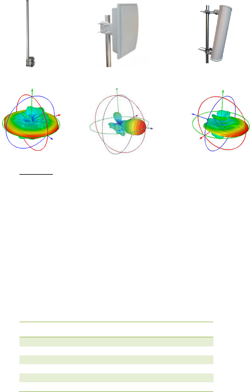
It is best practice to choose an antenna with a radiation pattern that will focus as much
power in the direction of the Eagle Field Device installation and not waist energy in directions
where there are none. For example, use a sector or panel antenna and not an
omnidirectional antenna if it is located at the one end of all the Eagles.
Some common antenna types are shown below together with an illustration of their radiation
patterns.
48
2.1.1.
Polarization
Antenna polarization is another property which the installer must bear in mind especially in
an environment with few obstacles.
A radio wave travelling in free space contains an electric field pointing in a perpendicular
direction to that of the propagation. The orientation of this electric field in the antenna’s main
beam is referred to as the antenna polarization. The electric field is described as either linear
or circular which means that the field is either orientated along a single axis or rotating as the
radio wave passes a point in space.
The Eagle is linearly polarized in the direction of its height and in order to achieve the
maximum range it must be orientated in the same direction as the polarization of the incident
radio wave. It is important to note that due to the prevalence of conductive surfaces in a
typical industrial environment, the incident radio wave polarization is likely not to be as the
purely polarized as the wave emitted in the Gateway antenna. This randomizing of the
polarization due to the interaction with conductive structures is why a good signal strength is
practically always achieved within 30m regardless of the Eagle orientation.
Never-the-less, being cognizant of the effect of polarization is very important and changing
either the Eagle or Gateway’s antenna polarization is one of the tricks discussed later in
order to improve the signal for hard to reach Eagle. The table below lists the signal loss due
to a mismatch in polarization.
Incident Wave Polarization
Eagle Orientation
Offset
Polarization Mismatch
Loss
Linear
0°
0dB
Linear
180°
0dB
Linear
45°
3dB
Linear
90°
∞
Circular Left-Hand
Any Direction
3dB
Circular Right-Hand
Any Direction
3dB
Omnidirectional
Panel antenna
Sector antenna

49
Brand of ACOEM

50
Chapter 8
APPENDIX 1: RADIO
Marque / Brand : OneProd
Le système EAGLE se compose d’une gateway, d’une antenne et de plusieurs capteurs
sans-fil (+accessoires) / Eagle system includes a gateway, an antenna, wireless sensors (+
accessories)
Type
Gateway
Capteurs
Modèle(s) / Model
NG1110
2010, 2030, 2010Ex,
2030Ex
Constructeur / Manufacturer
Divigraph (pty) LTD
Divigraph (pty) LTD
Bandes de fréquence émission/réception / Radiation/reception
frequency band
UHF ISM 2,400-2,4835 GHz
Largeur de bande des canaux / Channel Bandwidth
5MHz
Nombre de canaux / Nbr. of channels
16
Possibilité de choix des canaux /
OUI
Protocole radio / RF standard
IEEE 802.15.4
Protocole de communication / Communication protocol
ISA100.11a
Antenne intégrée / Internal antenna
Capteurs / Sensors 2010, 2030, 2010Ex,
2030Ex
Antenne externe / External antenna
Gateway NG1110
Puissance de l’émetteur / Output power of transmitter
<10mW
PIRE (puissance isotropique rayonnée équivalente) / EIRP
(Equivalent isotropically radiated power)
<10mW (10dBm)
PAR (Puissance apparente rayonnée), ERP (equivalent
radiated power)
Conforme CE / EC compliant
DAS (Débit d'absorption spécifique) / SAR (Specific absorption
rate)
Conforme CE / EC compliant
Les produits sont conformes aux exigences des directives suivantes / Products are compliants
with following directives
Directives
Gateway NG1110
Capteurs 2010, 2030,
2010Ex, 2030Ex
CEM / EMC
2004/108/EC
2004/108/EC
Directive courant faibles / Low voltage directive
2006/95/EC
2006/95/EC
R&TTE
1995/5/EC
1995/5/EC
Normes applicables à la conformité / Applicable standards
Normes / Standards
Gateway NG1110
Capteurs 2010, 2030,
2010Ex, 2030Ex
CEM / EMC
ETSI EN 55024 (1998
incluant A1 :2001 et A2
:2003)
IEC 61326-1 (2005)
ETSI EN 301 489-1 V1.9.2
(2011-09)
CISPR22 (2008)
Radio fréquence / Radio spectrum
ETSI EN 300 328 V1.7.1
(2006-10)
ETSI EN 300 328 V1.7.1
(2006-10)
Sécurité / Safety
IEC 60950 (2004)
ETSI EN 61010-1 (2010)
IEC 62479 (2010)

51
Brand of ACOEM