ACOEM VMT1002000 Vibration environment monitoring device User Manual
ACOEM Vibration environment monitoring device
ACOEM >
User manual.pdf
www.acoemgroup.com
support@acoemgroup.com
Copyright © 2014 - 01dB-Metravib SAS
This document is the property of 01dB-Metravib SAS. Any dissemination, copying or publicising of this
document, in whole or in part, is prohibited without the owner’s written authorisation
ORION Smart Vibration Monitoring Terminal
INSTALLATION & SAFETY INSTRUCTIONS

Brand of ACOEM

www.acoemgroup.com
support@acoemgroup.com
Copyright © 2014 - 01dB-Metravib SAS
This document is the property of 01dB-Metravib SAS. Any dissemination, copying or publicising of this
document, in whole or in part, is prohibited without the owner’s written authorisation
Document reference : NOT1561 February 2017 B
Name : ORION Installation & Safety instructions
ORION Smart Vibration Monitoring Terminal
INSTALLATION & SAFETY INSTRUCTIONS

4
Brand of ACOEM
TABLE OF CONTENTS
1. Safety Instructions ................................................................................... 7
1.1. General Safety Warnings ................................................................. 7
1.2. Definitions : Safety Guidelines ......................................................... 7
1.3. Safety Labels and markings ............................................................. 7
1.3.1. ID label on the back plate of the instrument ............................. 7
1.3.2. Markings next to the connectors ............................................... 8
1.3.3. Markings on the keyboard ......................................................... 9
1.3.4. Marking for Earth connection .................................................... 9
1.4. Operating environment ................................................................... 10
1.4.1. Instrument ............................................................................... 10
1.4.2. Power supplies ........................................................................ 10
1.5. Mechanical risk and work area safety ............................................ 11
1.6. Electrical safety .............................................................................. 12
1.6.1. Generalities ............................................................................. 12
1.6.2. External Power supplies ......................................................... 12
General information ............................................................. 12 1.6.2.1.
Standard power supply VMT1004000 ................................. 13 1.6.2.2.
Waterproof power supply VMT1007000 .............................. 14 1.6.2.3.
Existing Power Over Ethernet supply .................................. 16 1.6.2.4.
1.6.3. Inputs and Outputs .................................................................. 16
1.7. Personal safety ............................................................................... 17
1.8. Use and care .................................................................................. 17
1.9. Cleaning ......................................................................................... 17
1.10. Radio .......................................................................................... 18
1.10.1. General information ............................................................. 18
1.10.2. WIFI ..................................................................................... 19
1.10.3. GSM .................................................................................... 19
1.10.4. GPS ..................................................................................... 19
........................................................................................................... 20
1.11. Access hatch .............................................................................. 20
1.12. vent valve .................................................................................... 20
1.13. Service ........................................................................................ 20
1.14. Recycling and Waste disposal .................................................... 20
1.14.1. General information ............................................................. 20

5
Brand of ACOEM
1.14.2. Charge/Discharge................................................................ 21
1.15. Transportation ............................................................................. 22
1.16. Storage recommendations ......................................................... 22
2. General Presentation ............................................................................. 23
2.1. Introduction ..................................................................................... 23
2.2. Measurement domains ................................................................... 23
2.3. Overview......................................................................................... 24
2.4. Inputs sensors Description ............................................................. 25
2.4.1. Triaxial internal Accelerometer ............................................... 25
2.4.2. Triaxial external transducer ..................................................... 25
2.4.3. Microphone external sensor .................................................... 25
2.5. Antennas ........................................................................................ 25
2.6. Access hatch .................................................................................. 26
3. Installation.............................................................................................. 26
3.1. Use cases prerequisite ................................................................... 26
3.2. Flowchart for the installation........................................................... 26
3.3. Installation of the ORION with the optional Mounting Plate ........... 27
3.4. Power supply .................................................................................. 28
3.5. Earth connection ............................................................................ 29
3.6. General installation scheme ........................................................... 30
4. Maintenance .......................................................................................... 30
4.1. Generalities .................................................................................... 30
4.2. Parts replacement .......................................................................... 30
6
Brand of ACOEM
Welcome to the world of 01dB
ACOEM would like to thank you for purchasing this 01dB product and invites you to refer to this
installation and safety instructions. For more information on 01dB’s products and services, please
visit www.01db.com.
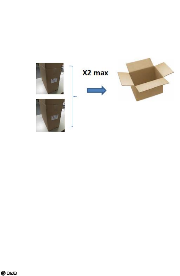
Receipt of your equipment
This product was carefully inspected and tested prior to shipping. Nevertheless, you are requested
to check when opening the packaging that there is no sign of damage and that all the accessories
are included. If this is not the case, please notify ACOEM or its approved representative without
further delay. You are advised to keep the packaging in case you need to return your equipment for
maintenance at ACOEM’s premises.
Warning
Before using the product, read the instructions carefully, especially the safety instructions
and the installation section
The safety instructions described in this manual should be adhered to and the instruments
should always be used within the limits specified hereafter. Instrument and operator safety is
at risk when the instrument is used in conditions that are not intended by ACOEM.
The User Manual (Computer version DOC1154), the Installation and Safety Instruction Manual
NOT1561 (computer and paper versions) provided with ORION must be read by the operator
before installation or starting to operate. Print this document or use a computer or a tablet to
keep them available, especially during installation;
Warranty
For this 01dB product, ACOEM offers a 24-month warranty for parts and labor, against all
manufacturing defects, with free shipment to return the equipment to ACOEM. Any defects or
damage caused by normal wear or resulting from negligence (poor supervision, maintenance or
storage conditions, misuse of product, etc.) or arising from modifications that are not allowed for nor
specified by ACOEM are excluded from the warranty. Up to the expiry date of the warranty period,
ACOEM undertakes to rectify any defect that adversely affects the normal operation of the product
and that fails within the scope of this warranty. In the event that such a defect should arise, you
should inform ACOEM is writing without delay, including any information liable to be useful in
diagnosing the nature of the defect and providing all supporting data as to the existence of the
defect.
For further information:
Visit our website at www.01db.com
Follow us on Twitter: http://twitter.com/01dB_acoem
Follow us on Facebook: https://www.facebook.com/pages/Acoem/
Follow us on LinkedIn: https://www.linkedin.com/company/01db-prevention-of-noise-&-vibration-
pollution
Contact our Customer Service Department by e-mail at 01db.support@acoemgroup.com
7
Brand of ACOEM
1. SAFETY INSTRUCTIONS
1.1. GENERAL SAFETY WARNINGS
WARNING! Read all safety warnings and all instructions. Failure to follow the warnings and
instructions may result in electric shock, fire and/or serious injury.
SAVE ALL WARNINGS AND INSTRUCTIONS FOR FUTURE REFERENCE.
Follow the "Quick Start Guide" and the “User Manual” that can be downloaded on:
http://support.01db.acoemgroup.com .
1.2. DEFINITIONS : SAFETY GUIDELINES
The definitions below describe the level of severity for each signal word. Please read the manual
and pay attention to these symbols:
Symbol
Description
WARNING: Indicates a potentially hazardous situation which, if not
avoided, could result in death or serious injury.
CAUTION: Indicates a potentially hazardous situation which, if not
avoided, may result in minor or moderate injury.
WARNING: indicates a potentially hazardous voltage
1.3. SAFETY LABELS AND MARKINGS
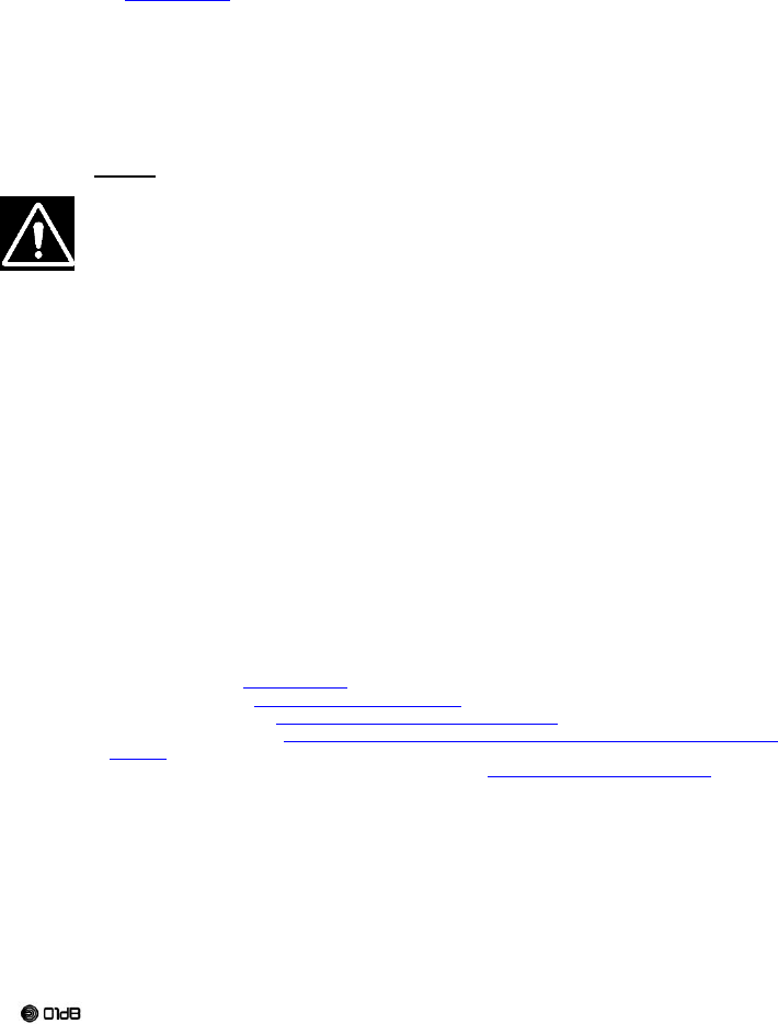
1.3.1. ID label on the back plate of the instrument
8
Brand of ACOEM
Symbol
Description
Discard the instrument with due care for the environment.
CE certification data. Refer to the copy of the UE certificate
Warning: Whenever this symbol is present on the device, it
is essential to refer to the safety instructions
documentation and the user manual.
FCC and IC statutory. Refer to section "Radio"
FCC and IC number. Refer to section "Radio".
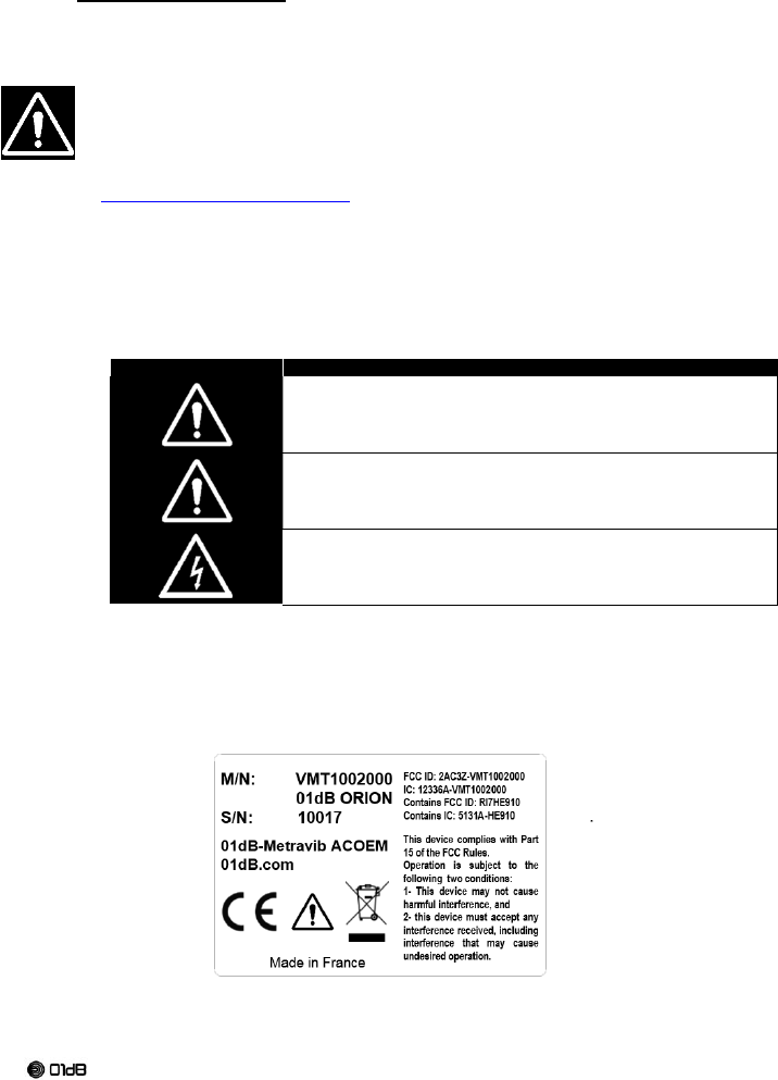
1.3.2. Markings next to the connectors
Connector #
Symbol
Description
C1
External sensors
( means dc: direct current)
Constant Current output 4 mA dc at +24
Volts max
C2
TTL output
( means dc: direct current)
+3,3 V dc at 30 mA max
C3
External input Power; Respect tension
and current.
( means dc: direct current)
+12 Volts nominal dc at 1,3 A max
Refer to section external supply (§1.6.2)
C4
Ethernet / External Power over Ethernet;
( means dc: direct current)
+48 Volts dc nominal at 0,3A max
Respect tension and current.
Refer to section PoE (§1.6.2.4)
9
Brand of ACOEM
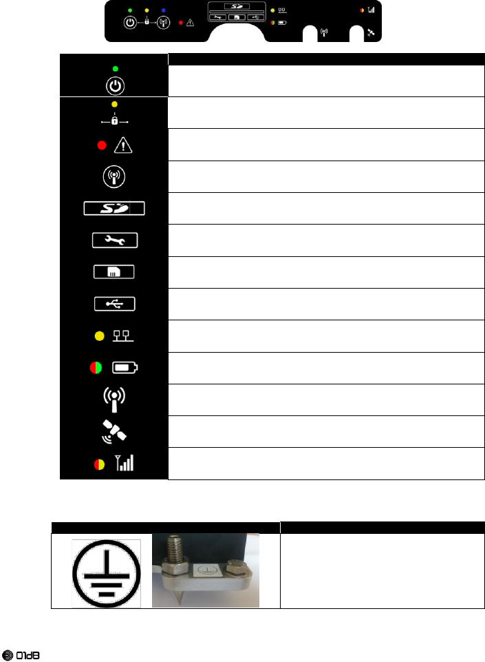
1.3.3. Markings on the keyboard
Symbol
Description
Power button
Power LED
Lock LED
Sensor error LED
Wi-Fi button
Wi-Fi LED
Memory SD (solid disk) card slot (Behind the hatch)
Micro-USB Factory service only (Behind the hatch)
SIM card slot (Behind the hatch)
Micro-USB Connector (Behind the hatch)
Ethernet LED
Battery LED for charge level indication
Wi-Fi antenna connector
GPS Connector
GSM antenna connector
LED for quality signal
1.3.4. Marking for Earth connection
Symbol
Description
Label Earth protection

10
Brand of ACOEM
1.4. OPERATING ENVIRONMENT
Don't use this instrument, its accessory and its power supply in explosive atmosphere, or near
flammable products, or near corrosive products.
1.4.1. Instrument
The instrument has a protection degree IP65 (IEC60529) when hatch is closed and connector's
bases are equipped of their protections or their connectors.
The instrument has a protection degree IP20 (IEC60529) when hatch is opened.
In an industrial environment, always use the instrument equipped with its connector hatch. Check
the presence of the seals and their condition prior to any use. Check the tightening of the hatches.
In an office environment (no water splashes), the instrument can be used when the hatch is open.
Whenever the instrument is used outside, it must have hatch closed and connector's bases
equipped of their protections or their connectors.
The instrument (excluding power supply) is designed to operate in environmental conditions as
described in Standard IEC61010-1:
Altitude up to 2,000 m;
Temperature from 5°C to 40°C.
Pollution rating 2
maximum relative humidity 80 % for temperatures up to 31 °C decreasing linearly to 50 %
relative humidity at 40 °C;
And the following extended conditions:
Outdoor use.
Pollution rating 4
Wet Location
ambient temperatures from -10°C to 55°C.
95% humidity, no condensation.
Warning: The operating environments for power supplies are not the same than for the
instrument ORION.
Take care to respect the most constraining environment if the power supplies are used.
1.4.2. Power supplies
Respect the emplacement for the power supply.
Use only the power supply described in this document.
Only the waterproof power supply may be used outdoor.
For more information on the environment of Power supplies, Refer to §1.6.2 External Power
supplies)
11
Brand of ACOEM
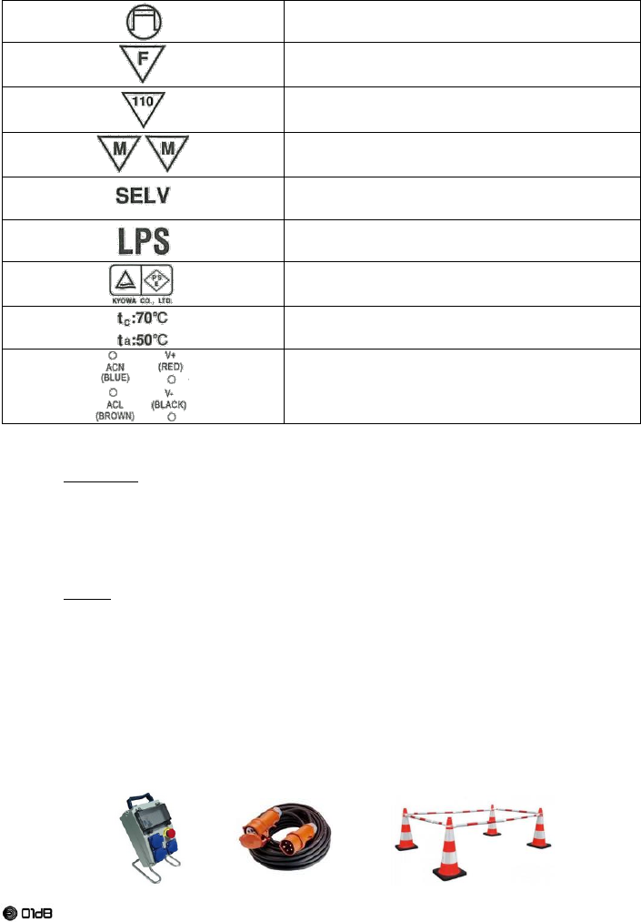
1.5. MECHANICAL RISK AND WORK AREA SAFETY
Keep work area clean and well lit. Cluttered or dark areas invite accidents.
Ensure the cables connected to the instrument are secure, protected and fixed to avoid hanging
on or falling.
A mark-up and/or a mechanical protection must be put in place to protect the instrument
As the device is heavy, wear security shoes to prevent injury from a drop.
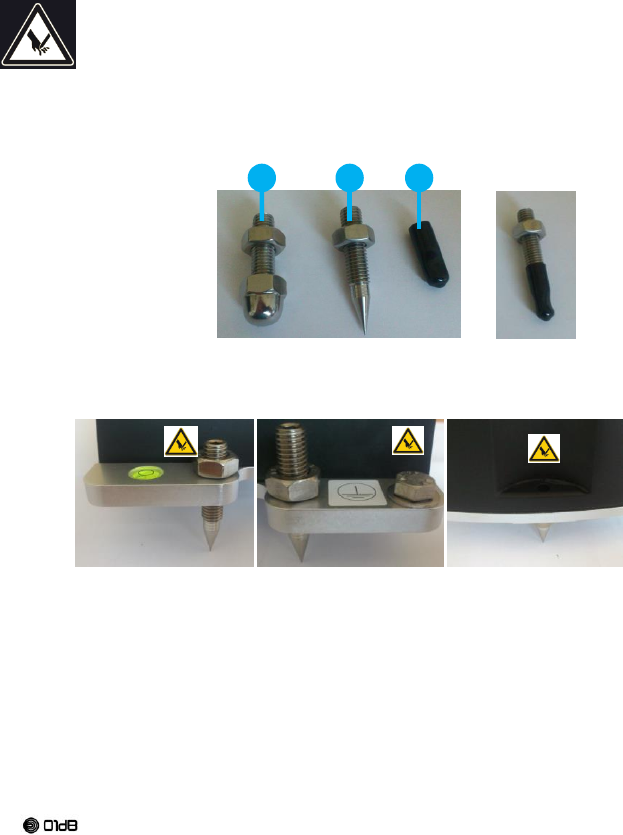
As standard, the device is equipped with three feet with spherical extremity
Optionally, the device can be equipped with three feet with very sharp extremity
Be very careful to prevent injury by the sharp extremity.
Use gloves to prevent injury when manipulating
When not used, cover the sharp extremities with their cap.
When installing the device, keep the protective cap as long as possible and remove it at the last
time.
When the sharp feet are in place on the device, always turn them to the ground. Never let the
device with the sharp feet turned up.
The sharp feet are provided in a bag with three warning labels and a safety warning. Stick the
labels as explained.
01 – Standard foot
02 – Optional sharp foot
03 – Protective cap
01
02
03

12
Brand of ACOEM
1.6. ELECTRICAL SAFETY
1.6.1. Generalities
All external circuits connected to ORION should be non-hazardous voltage, and energy
source limited within the meaning of the IEC61010-1 standard.
The power supply must be connected to the mains power equipped with a differential circuit
breaker.
The power supply is the main disconnecting device in the system and, as such, should remain
always perfectly accessible and disconnectable
The power outlet must be in an accessible location for fast unplug if there is a need for fast
disconnection.
The instrument and power supply plugs must match the outlet. Never modify the plug in any way.
Unmodified plugs and matching outlets will reduce risk of electric shock.
Do not abuse the cord. Never use the cord for carrying, pulling or unplugging the instrument.
Ensure the power supply is connected to an outlet protected from shocks or possible damage.
Keep cord away from heat, oil, sharp edges or moving parts. Damaged or entangled cords
increase the risk of electric shock.
When operating the instrument outdoors with the optional outdoor power supply, use an extension
cord suitable for outdoor use. Use of a cord suitable for outdoor use reduces the risk of electric
shock.
The connection of the safety ground on the housing is essential using cables outside the building
1.6.2. External Power supplies
Observe the recommended Power supply is very important for the instrument safety.
General information 1.6.2.1.
The instrument can be powered by four type of external power supply
A standard power supply which can only be used in an Indoor environment.
A Waterproof power supply which can only be used in an Indoor and Outdoor environment
The instrument can also be powered by an existent Ethernet Lan providing the power supply over
Ethernet (PoE). Observe the electrical safety rule for this case.
The Standard power supply and the waterproof power supply come on the C3 External Power
The Ethernet power supply come on the C4 Ethernet connector.
13
Brand of ACOEM
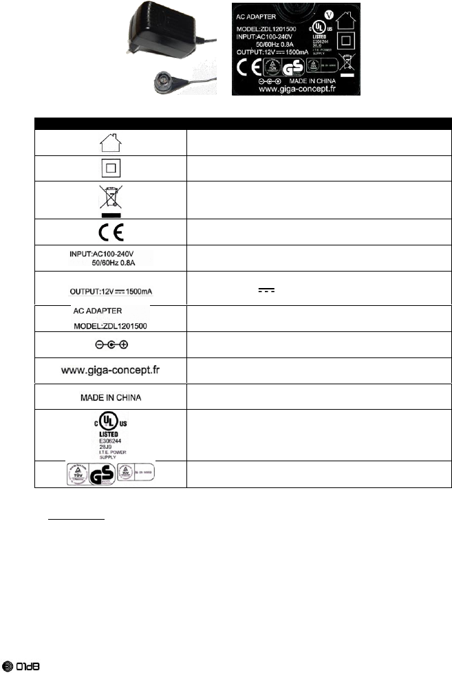
Standard power supply VMT1004000 1.6.2.2.
GC-ZDL1201500 GIGA-Concept Electronics components
Symbol
Description
Only for indoor use
The power supply is double insulated in accordance with
EN 60335; therefore no earth wire is required.
Discard the power supply with due care for the
environment.
CE label
Input Electrical characteristics
100-240V AC frequency 50 to 60Hz at 0,8 A max
Output Electrical characteristics
( means dc: direct current)
+ 12 V dc at 1500 mA max
Identification : Model number
Output connector modified with cylindrical connector
manufacturer
Country
UL mark
TUV Mark
Environment:
Indoor only, altitude up to 2 000 m;
Operation 0 to 35°C
MAINS supply voltage fluctuations up to ±10 % of the nominal voltage
TEMPORARY OVERVOLTAGES occurring on the MAINS supply
TRANSIENT OVERVOLTAGES up to the levels of OVERVOLTAGE CATEGORY ll
TEMPORARY OVERVOLTAGES occurring on the MAINS supply
- Do not use the standard power supply outdoors.
- To connect to the mains power, first connect the cylindrical plug C3 on the instrument, and
connect the power supply to the power outlet. Proceed in reverse order to disconnect.
14
Brand of ACOEM
- Pull by body rather than cord when disconnecting standard power supply. This will reduce
risk of damage to electric plug and cord.
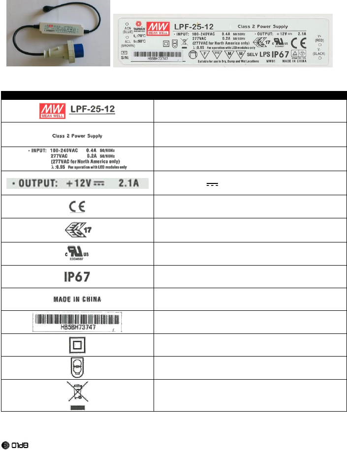
Waterproof power supply VMT1007000 1.6.2.3.
Part number LPF-25-12
Symbol
Description
Product identification
The device has reinforced insulation without accessible
metal part. Devices of class 2 does not need a ground pin
Note: the ground pin on the input plug is not connected
Input Electrical characteristics
100-240V AC frequency 50 to 60Hz at 0,4 A max
(Ignore other marking)
Output Electrical characteristics
( means dc: direct current)
+ 12 V dc at 2,1 A max
CE mark
ENEC mark
(ENEC is the high quality European Mark for electrical
products)
Component UL recognized
International Protection degree for the module
Production country
Serial number
The power supply is double insulated in accordance with
EN 60335; therefore no earth wire is required.
The power supply has a safety transformer
Discard the power supply with due care for the
environment.
15
Brand of ACOEM
*Device independent auxiliary lighting
*For direct mounting on flammable surfaces, such as wood
(> 2mm)
*Protection to avoid the lamp controlgear overheat
whatever the conditions of use excedantes the value
indicated (110 ° C)
*Could be mounted inside wood part. The minimal distance
between the product and the wood part has to be respected
(Please refer to VDE0710-14A)
*Safety extra low voltage
*Limited power source
TUV Rheinland of North America
The PSE Mark is a mandatory mark for Japan according to
the Electrical Appliance and Material Safety Law
Temperature information
Connexion Information
*Specifical information for lighting applications (not involved for ORION)
Environment:
Indoor and outdoor
Operation -20°C to 55°C without derating
MAINS supply voltage fluctuations up to ±10 % of the nominal voltage
TEMPORARY OVERVOLTAGES occurring on the MAINS supply
TRANSIENT OVERVOLTAGES up to the levels of OVERVOLTAGE CATEGORY ll
TEMPORARY OVERVOLTAGES occurring on the MAINS supply
Warning
ORION powered by this supply is a class A product. In a domestic environment this product may
cause radio interference in which case the user may be required to take adequate measures. See
EU declaration of conformity.
- When operating the optional outdoor power supply, always avoid locations where the power
supply or the connectors may be submerged. Use imperatively an extension cord suitable for
outdoor to avoid the risk of electric shock.
- To connect the mains, first connect the cylindrical plug C3 on the instrument, and connect the
power supply to the power outlet. Proceed in reverse order to disconnect.
- Mark the area to protect the power supply from shock
16
Brand of ACOEM
Existing Power Over Ethernet supply 1.6.2.4.
Two cases possible:
The existing Power over Ethernet supply to ORION must conform to IEC 61010-1: 2010 and EN
61010-1: 2010 and all their applicable Amendments ".
The output circuits of these power supplies must have safe voltage levels and power be limited in
the sense of these standards.
or
The existing Power over Ethernet supply to ORION must comply with IEC 60950-1: 2005 and EN
60950-1: 2006 and all their applicable Amendments."
The output circuits of these power supplies must be of the Safety Extra Low Voltage (SELV) and be
Limited Power Sources in the sense of these standards.
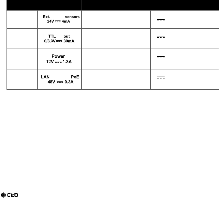
1.6.3. Inputs and Outputs
All external circuits connected to ORION should be non-hazardous voltage and energy
sources be limited within the meaning of the IEC61010-1 standard.
Do not exceed the maximum input voltage on the connectors.
Connector
#
Symbol
Description
Maximum voltage and
current
C1
External sensors
DC input with current générator
( means dc: direct current)
+24V dc max at 4mA
C2
TTL output
TTL Output
( means dc: direct current)
+3.3V dc max at 30 mA
C3
External Power; Respect
tension and current.
Refer to section external supply
Input power
( means dc: direct current)
12V dc nominal at 1.3A
Min 9V / Max 15V
C4
Ethernet / External Power over
Ethernet; Respect tension and
current.
Refer to section PoE
Input ethernet power
( means dc: direct current)
+48V dc at 0.3A
Min 46V : Max 50V

17
Brand of ACOEM
1.7. PERSONAL SAFETY
Stay alert, watch what you are doing and use common sense when installing and operating the
instrument. Due to its weight and shape, the manipulation of the instrument can result in minor or
moderate injury, especially if the spikes are mounted.
In case of use of spikes, the spike protection must remain in place until the instrument is placed at
its measurement position.
Use personal protective equipment. In particular, safety shoes and possibly gloves when handling
the instrument. This equipment is not provided with the system and must be provisioned by the
user.
1.8. USE AND CARE
Before any use, visual inspect the instrument case and its accessories and check there is no
visible damage such as crack, broken part or abnormal deformation.
Check the access hatch cover is correctly mounted and screwed.
The instrument must be properly connected to the earthing system (use of optional cable + stake if
no earth connection available) (refer to §3.5 Earth connection)
The connection to the earthing system must be done before connecting the instrument power
supply to the mains.
Do not install nor uninstall all or part of the equipment in stormy weather.
Do not install nor uninstall all or part of the system in explosive areas.
Do not install the equipment next to flammable chemical products or unknown things.
The instrument must be protected as much as possible against direct exposure to sun in order to
limit heat-up.
Always put in place the connectors cover.
Disconnect the plug from the power source before changing accessories or storing the instrument.
The instrument should not be used at altitudes above 2000m.
1.9. CLEANING
Disconnect the instrument before attempting to clean.
Close the hatch before cleaning.
Protect the connectors with their cap before cleaning.
Use non aggressive products to clean the instrument, as diluted detergent (dishwashing liquid, or
soap)
Start on little hided surface to be sure of the right product choice.
Do not insist on labels to avoid erase them.
Forbid aggressive product as acids, ammoniac, acetone,

18
Brand of ACOEM
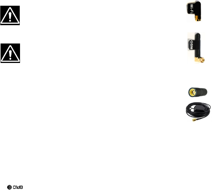
1.10. RADIO
1.10.1. General information
The instrument is capable of connecting to Wi-Fi and 3G wireless networks. Modems Wi-Fi and 3G
are qualified for EMC and safety. This qualification is valid only with the antennas supplied with
the unit and referred in this document.
The instrument is also capable of receiving GPS satellites data
This device complies with FCC and IC RF radiation exposure limits set
forth for general population. This device must be installed to provide a
separation distance of at least 20cm from all persons and must not be co-
located or operating in conjunction with any other antenna or transmitter.
Caution: Changes or modifications not expressly approved by the party
responsible for compliance could void the user's authority to operate the
equipment.
1. FCC (USA):
This device complies with Part 15 of the FCC Rules. Operation is subject
to the following two conditions: (1) this device may not cause harmful interference, and (2) this
device must accept any interference received, including interference that may cause undesired
operation.
For Standard Power supply VMT1004000:
NOTE: This equipment has been tested and found to comply with the limits for a Class B digital
device, pursuant to part 15 of the FCC Rules. These limits are designed to provide reasonable
protection against harmful interference in a residential installation. This equipment generates, uses
and can radiate radio frequency energy and, if not installed and used in accordance with the
instruction, may cause harmful interference to radio communications. However, there is no
guarantee that interference will not occur in a particular installation. If this equipment does cause
harmful interference to radio or television reception which can be determined by turning the
equipment off and on, the user is encouraged to try to correct interference by one or more of the
following measures:
Reorient or relocate the receiving antenna.
Increase the separation between the equipment and receiver.
Connect the equipment into an outlet on circuit different from that to which the receiver is
connected.
Consult the dealer or an experienced radio/TV technician for help.
For Waterproof power supply VMT10070000
Note: This equipment has been tested and found to comply with the limits for a Class A digital
device, pursuant to part 15 of the FCC Rules. These limits are designed to provide reasonable
protection against harmful interference when the equipment is operated in a commercial
environment. This equipment generates, uses, and can radiate radio frequency energy and, if not
installed and used in accordance with the instruction manual, may cause harmful interference to
radio communications. Operation of this equipment in a residential area is likely to cause harmful
interference in which case the user will be required to correct the interference at his own expense.
19
Brand of ACOEM
2. IC: (industry Canada)
Under Industry Canada regulations, this radio transmitter may only operate using an antenna of a
type and maximum (or lesser) gain approved for the transmitter by Industry Canada. To reduce
potential radio interference to other users, the antenna type and its gain should be so chosen that
the equivalent isotropically radiated power (e.i.r.p.) is not more than that necessary for successful
communication.
This radio transmitter (IC: 12336A-VMT1002000) has been approved by Industry Canada to operate
with the antenna types listed below with the maximum permissible gain and required antenna
impedance for each antenna type indicated. Antenna types not included in this list, having a gain
greater than the maximum gain indicated for that type, are strictly prohibited for use with this device.
ORION is equipped with 2.4GHz Mini Stubby Antenna model ANT-24G-S21, 50 ohms, 0 dBi.
Only use this model of antenna.
This device complies with Industry Canada license-exempt RSS standard(s). Operation is subject to
the following two conditions: (1) this device may not cause interference, and (2) this device must
accept any interference, including interference that may cause undesired operation of the device.
This class (B) digital apparatus complies with Canadian ICES-003
1.10.2. WIFI
Wifi modem is qualified for Safety and EMC. This qualification is valid only with the
antenna supplied with the unit.
Reference of the antenna: VMT1029000
1.10.3. GSM
GSM modem (3G+) is qualified for safety and EMC. This qualification is valid only
with the antenna supplied with the unit.
Reference of the antenna: VMT1030000
1.10.4. GPS
Two antennas types can be used:
Antenna (ACE1105) mounted directly on ORION if satellites reception is satisfactory
at ORION location.
GPS patch (ACE1094) to be able to mount the patch at a different location from
where ORION is for better satellites reception; 3 meters cable.
20
Brand of ACOEM
1.11. ACCESS HATCH
The access hatch must be opened only in an office atmosphere with a desk-
counter pollution less than 2.
Do not forget to mount it before going on a job site
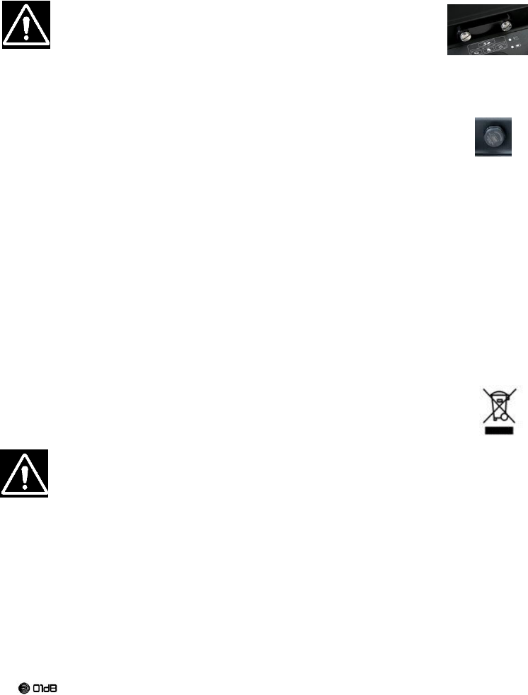
1.12. VENT VALVE
The instrument has a breath valve with a membrane which allows respiration, but stop
humidity.
Breathing valve must not be obstructed or blocked
1.13. SERVICE
The disassembly for internal repair is prohibited.
The service of the ORION has to be performed by a qualified person using only original
replacement part. This will ensure that the safety of the instrument is maintained.
1.14. RECYCLING AND WASTE DISPOSAL
In no event should this instrument be thrown in trash. It must be disposed of according to the WEEE
directive. Waste disposal and recycling procedures complaint with WEEE* shall be adopted.
*WEEE: Waste Electrical and Electronic Equipment
The instrument and accessories should be recycled as electronic product incorporating a battery.
The instrument and its accessories should not be incinerated or thrown into the fire
The instrument and its accessories must not be landfilled.
The instrument and its accessories must neither be ground nor crushed.
1.14.1. General information
The internal battery is not replaceable by the User.
The internal battery is not accessible by the User.
The battery pack must be replaced at factory only by authorized personnel
Anyway,
Do not open or dismount the battery pack. The pack includes essential safety protections and
assembly that should in no event be modified.
The battery pack can only be replaced for maintenance purposes. The operating lifetime of the
pack is long enough to guarantee a full day of continuous work.
Do not short circuit the terminals of the battery connector (note: for safety reasons, the battery
pack is equipped with an internal non resettable fuse. A short circuit would make the battery pack
unusable).
Respect the voltage, current and temperature ranges listed on the battery label.
Do not exert excessive mechanical pressure on the battery pack.
Do not expose the battery to water or condensation.

21
Brand of ACOEM
Do no place the battery into fire or close to any other temperature source (> 70°C). This action
may cause overheating, even start a fire. This type of use may also lead to degraded
performances and to a significantly reduced lifetime for the battery.
Immediately disconnect the power supply in the event of one of the following situations:
o unusual odour
o unusually high temperature
1.14.2. Charge/Discharge
The battery is charged by an internal charger.
The external power supply provides energy to the instrument for his functioning and also for the
battery recharge. The priority is always given to instrument functioning.
During the charge, the battery temperature arises. The charger senses the temperature to maintain it
under a safety level. If the temperature begins too high, the charger will stop the charge.
The maximum ambient temperature for a full charge rate at 3A is 36°C
Otherwise, the current charge would be stop as long the temperature is too high.
22
Brand of ACOEM
1.15. TRANSPORTATION
Safety instructions for Lithium Ion :
The instrument together with its integrated Lithium Ion battery comply with all applicable shipping
regulations as prescribed by industry and legal standards which include UN Recommendations on
the Transport of Dangerous Goods; International Air Transport Association (IATA) Dangerous Goods
Regulations, International Maritime Dangerous Goods (IMDG) Regulations, and the European
Agreement Concerning The International Carriage of Dangerous Goods by Road (ADR). Lithium-ion
cells and batteries have been tested to section 38.3 of the UN Recommendations on the Transport
of Dangerous Goods Manual of Tests and Criteria.
The instrument has the classification number UN3481.Section II Package instruction 967.
Each unit is individually wrapped. Two products are allowed in the shipping carton. They must be
secured inside.
It is the expeditor responsibility to comply with the applicable regulations.
1.16. STORAGE RECOMMENDATIONS
The best storage place is a cool and dry area away from direct sunlight and excess heat or cold.
For optimum battery performance and life, store the instrument between 15°C and 25°C
For long storage, it is recommended to store a fully charged instrument in a cool, dry place out of
the power supply
Observe the storage temperature -20 ° C <T ° storage <70 ° C
NOTE: The instrument should not be stored completely depleted of charge. The battery will need to
be recharged before use.

23
Brand of ACOEM
2. GENERAL PRESENTATION
2.1. INTRODUCTION
ORION is a new generation upgradeable vibration measuring instrument, integrating innovative
technology. The programming of all available functions (Input / Output / Storage…) allows meeting
best the user’s requirements.
The data measured with the instrument are displayed on a remote screen, such as a tablet,
smartphone or laptop, using an off-the-shelf networked device equipped with Wi-Fi or 3G
connectivity and a web browser, in conjunction with the web interface, the web server built into the
instrument. This function offers access to all the functions of the instrument (measurement and
system configuration, real-time display…).
A status bar visible on the web interface gives the operator a quick overview of the device status and
the current measurement. At any time, the user can access more detailed information looking at the
different menus available. For instance, the user is informed about the remaining battery lifetime
(depending on parameters of the selected configuration), disk space available etc.
The integrated Ethernet, Wi-Fi and 3G communication features give the user complete control of the
instrument (configuration, real-time values, stored data…), with equal ease adjacent to the
measurement point (a few dozen meters away using point-to-point Wi-Fi) and at a distance (3G).
Hence, the interest for simultaneous measurement in several points and as a result getting fully
synchronised and geo-referenced results using several instruments with built-in GPS component
and external antenna or patch.
2.2. MEASUREMENT DOMAINS
Vibrations on buildings: e.g. damage caused on a building site by a neighbour
Vibrations on occupants: e.g. vibrations near a railway
Vibrations on sensitive equipment: e.g. work in the museum neighbourhood or sensitive
computers.
The evaluation of vibration is based on velocity or acceleration acquisition on three axes X, Y, Z in
the band 0.4Hz-150 or 500Hz frequency. According to the standards of different countries, the
measured quantities are compared to tolerance curves whose values may differ depending on the
frequency.
24
Brand of ACOEM
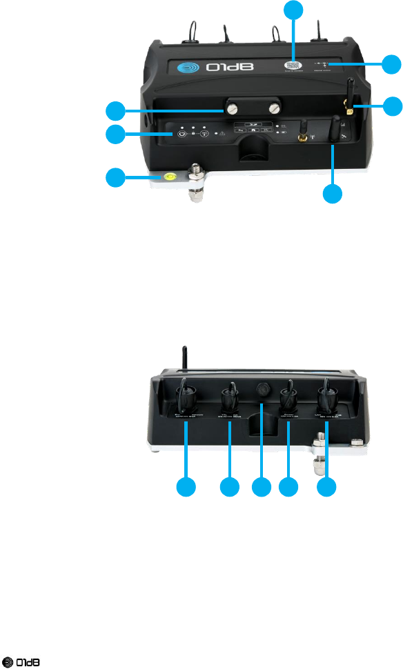
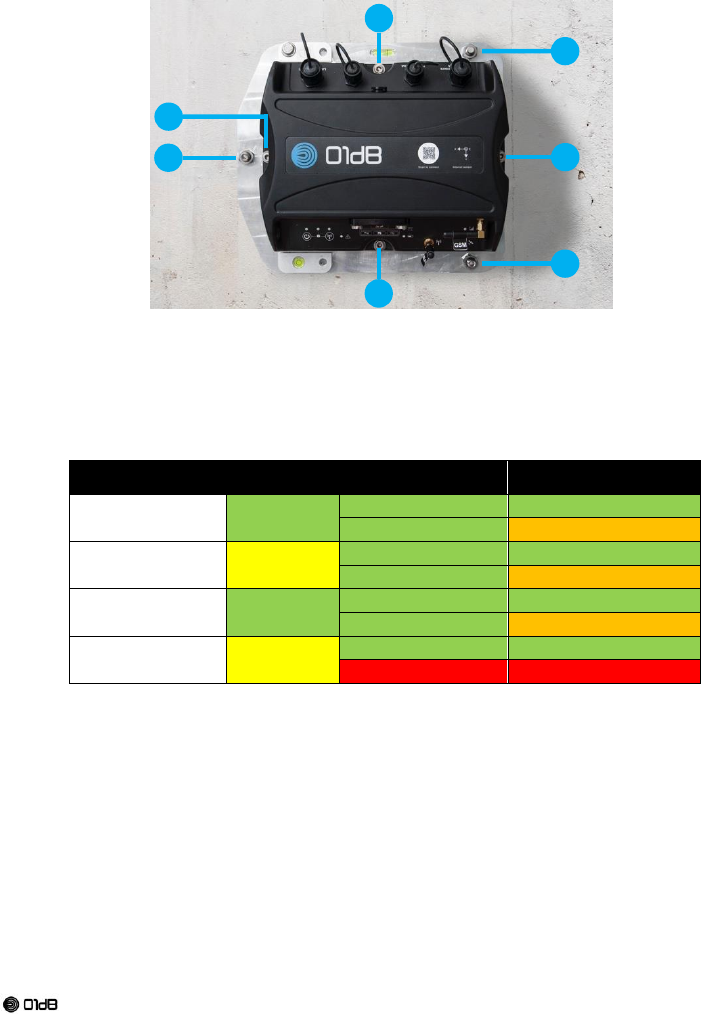
2.3. OVERVIEW
Front view
01 – Hatch access to connectors SD, USB, SIM and service
02 – Keyboard
03 – Bubble level for horizontal adjustment
04 – Wi-Fi antenna
05 – GPS antenna (optional)
06 – 3G antenna
07 – Internal sensor directions
08 – QR code
Back view
09 – C1 - External sensors
10 – C2 - TTL Output
11 – Breathing valve
12 – C3 - External Power
13 – C4 - Ethernet / External Power over Ethernet (PoE)
01
02
03
08
07
06
09
05
13
10
12
11
25
Brand of ACOEM
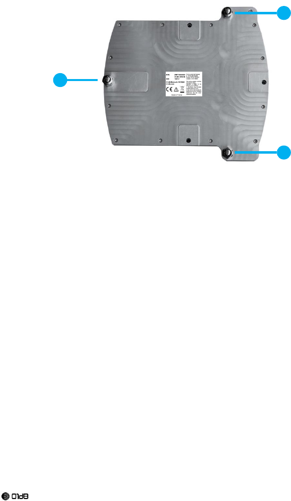
Bottom view
14 – Adjustable screws
15 – Not adjustable screw
2.4. INPUTS SENSORS DESCRIPTION
2.4.1. Triaxial internal Accelerometer
The device internally has a triaxial accelerometer to perform the majority of the measurements.
2.4.2. Triaxial external transducer
It is also possible to connect on C1 connector in place of or in parallel to the internal sensor an
external triaxial accelerometer sensor or triaxial velocity meter sensor.
This external sensor allows to evaluate vibration in other measuring ranges or be positioned on a
specific place.
2.4.3. Microphone external sensor
It is also possible to connect on C1 connector a microphone to measure the noise associated with
the vibration (blast). Contact us for this feature.
2.5. ANTENNAS
For detailed description, please refer to § 1.10
15
14
14
26
Brand of ACOEM
2.6. ACCESS HATCH
The waterproof access hatch must be screwed using the knurled head screws with the torque
allowing the user to unscrew them with fingers. It gives access to several slots:
SD card slot
Sim card slot
Micro USB connectors for USB host connection (allows for reading the SD card content) and
factory service
3. INSTALLATION
The equipment can be deployed in different configurations. All configurations are not allowed
according to the environment. It is essential to observe the deployment and safety rules that
apply to each use case.
3.1. USE CASES PREREQUISITE
Use cases are exhaustively described. Other use case, which are not described on this document,
are not allowed for this instrument
l.
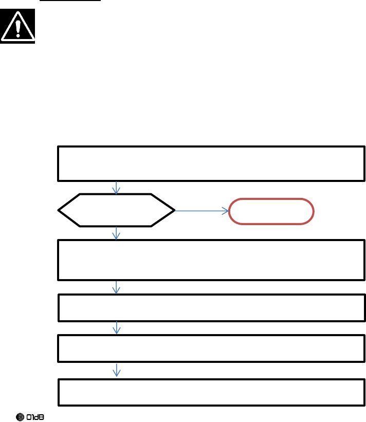
3.2. FLOWCHART FOR THE INSTALLATION
Define the position of the instrument and eventually its external sensors (Outside, Inside)
Define the external device using eventually the TTL output
Define the power supply
Before connecting power supply or switch on power,
Connect the external sensors (if needed)
Connect the external TTL device (if needed)
Connect the Ethernet cable (if needed)
Check the conditions
(3.4 Power supply)
Connect the protection earth (if needed)
(§ 3.4 Power supply and § 3.5 Earth connection)
Set precisely the horizontality of the instrument using the adjustable levelling plate.
Set precisely the orientation of the instrument
Not OK=> STOP
Connect the power supply to the mains (if needed)
Start the instrument

27
Brand of ACOEM
3.3. INSTALLATION OF THE ORION WITH THE OPTIONAL MOUNTING PLATE
The ORION could be fixed on concrete floor or wall using the optional mounting plate
(VMT1013000A).
The 4 M6 screws needed to fix the ORION on the Interface plate are included in the delivery.
The 3 expanding studs needed to fix the mounting plate on the concrete are not delivered and must
be selected by the operator according to the type of wall support.
To compensate for imperfections of planeness of the floor or wall, the mounting plate is delivered
with washers to insert between the mounting plate and the supporting floor or wall.
To perform the installation, the user has to:
Wear adapted PPE (safety glass, safety shoes, gloves, ear plug…)
Check the safety of the drilling operation (no electrical wires, pipe… inside the wall)
Have the drilling ability
Check that the type of wall is adapted to the weight of the ORION (for wall installation) –
Installation on a plasterboard partition is forbidden
Check that the expanding studs are adapted to the weight of ORION. ACOEM recommend a
Ø10mm expanding stud
Follow the expanding stud installation instructions provided by the manufacturer.
To fix ORION on the wall please follow these steps:
Place the mounting plate without ORION on the wall at the selected location
Adjust the horizontality of the mounting plate with the spirit level
Mark the location of the fixation point #1 (Indication 01 on the following picture)
Remove the mounting plate and drill the first hole
Remove dust from the hole
Loosely screw the mounting plate on the wall with one expanding stud and a washer (between
mounting plate and the wall)
Adjust the horizontality of the mounting plate with the spirit level and drill the second and third
holes (using the mounting plate as a guide)
Tilt the mounting plate to access the holes Remove dust from the 2 holes
Screw and tighten the mounting plate on the wall with the 3 expanding studs and washers
(between mounting plate and the wall)
Remove the feet of ORION, screw and tighten ORION on the mounting plate with the 4 M6 screws
(Indication 04 on the following picture)
To fix ORION on the floor please follow these steps:
Place the mounting plate without the ORION on the floor at the selected location
Mark the location of the fixation point #1 (Indication 01 on the following picture)
Remove the mounting plate and drill the first hole
Remove dust from the hole
Loosely screw the mounting plate on the floor with one expanding stud and a washer (between
mounting plate and the wall)
Drill the second and third holes (using the mounting plate as a guide)
Tilt the mounting plate to access the holes
Remove dust from the 2 holes
Remove the feet of ORION, screw and tighten ORION on the mounting plate with the 4 M6 screws
(Indication 04 on the following picture)
Place the mounting plate and the ORION in front of the 3 holes and adjust the horizontality with
washer (between floor and mounting plate)
Screw and tighten the mounting plate on the floor with 3 expanding studs
28
Brand of ACOEM
01 – Wall/floor fixation point #1
02 – Wall/floor fixation point #2
03 – Wall/floor fixation point #3
04 – ORION fixation point on mounting plate
3.4. POWER SUPPLY
Power supply
Power supply
position
Instrument position
Earth Protection*
Internal battery
Indoor
or
Outdoor
Indoor: Allowed
recommended
Outdoor: Allowed
Strictly necessary
Standard power
supply
Indoor Only
Indoor: Allowed
recommended
Outdoor: Allowed
Strictly necessary
Waterproof power
supply*
Indoor
or
Outdoor
Indoor: Allowed
recommended
Outdoor: Allowed
Strictly necessary
PoE on an existing
PoE network
Indoor Only
Indoor: Allowed
recommended
Outdoor: Not Allowed
*Only waterproof power supply can be connected from the outside
All external circuits connected to ORION should be non-hazardous voltage and energy
sources be limited within the meaning of the IEC61010-1 standard.
The earth protection is strictly necessary for every case below listed:
Instrument ORION is outside of a building.
One Sensor or more of ORION are outside of a building.
One cable or more are outside of a building.
One cable or more use paths where there are others cables.
The TTL output is connected to a device powered by the mains
However, for the other cases, the earth protection is recommended for a better safety.
If the instrument ORION is connected to an existing PoE Network, this PoE should be non-
hazardous voltage and energy source be limited within the meaning of the IEC61010-1
standard.
01
02
03
04
04
04
04
29
Brand of ACOEM
If the TTL output of the instrument ORION is connected to a device, this device should be
non-hazardous voltage and energy source be limited within the meaning of the IEC61010-1
standard
The radio device (WIFI, GSM-3G, GPS) may be used in accordance of national regulations (RED,
FCC, IC).
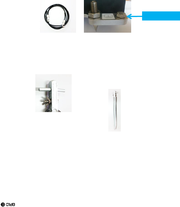
3.5. EARTH CONNECTION
The protective Earth connexion is possible on the screw terminal using the cable as shown on the
picture. The recommended tightening torque is 3N.m. The screw is furnished (M8).
The other side of the earth cable must be connected to a good quality protective earth.
The Integrity of protective bonding must be in respect of the IEC61010-1 (cf 6.5.2 Protective
bonding)
For outside situation, the protective earth may use a solid ground rod galvanized steel.
The rod must be should be buried at least 60 cm. The ground must be wet permanently. If
necessary, spray water at periodical time to maintain humidity.
An existing protective ground may either used in replacement of the ground rod.
Whenever, it must compliant to the IEC61010-1 standard (cf 6.5.2 Protective
bonding)
Screw Terminal
30
Brand of ACOEM
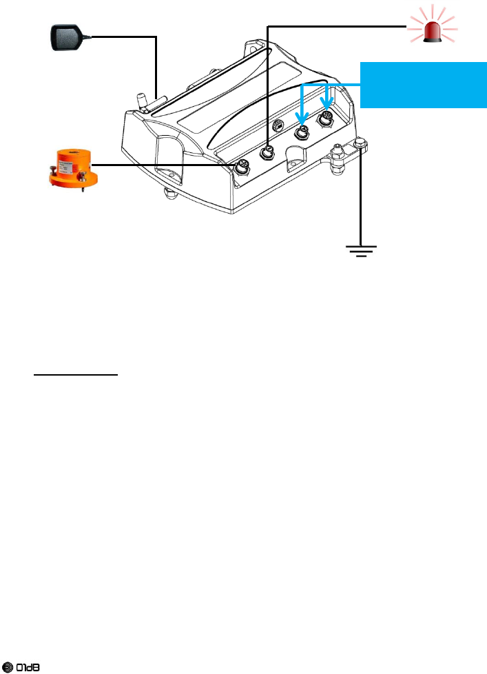
3.6. GENERAL INSTALLATION SCHEME
All additional devices (GPS patch, TTL input, External sensor) could be connected from indoor to
outdoor. In this case a protective earth has to be installed (§3.5 Earth connection).
The maximum length of the cable is 10 meters.
4. MAINTENANCE
4.1. GENERALITIES
The device does not need maintenance or adjustment excluding cleaning and battery replacement.
The internal battery is not replaceable by the user.
The battery pack must be replaced at factory only by authorized personnel
4.2. PARTS REPLACEMENT
The parts of the device ORION that could be replaced by the owner are:
The three feet, spherical or sharp end
The antenna
The cables or accessory
The power supplies
The access hatch
The replacement part must be provided only by the manufacturer.
The power supply and their cord must be provided only by the manufacturer
GPS patch antenna
Ext. sensor
TTL input device
Protective Earth
Ext. Power supply
C3 (power supply) or
C4(PoE)

31
Brand of ACOEM

32
Brand of ACOEM
ACOEM
Smart monitoring, diagnosis & solutions
In today’s complex and increasingly fast-moving world, it is essential to keep risks
under control. ACOEM helps customers in the industrial, environmental and defense
sectors make the right decisions and take the right actions:
to ensure the productivity and reliability of industrial machines
to prevent noise and vibration pollution
to protect personnel, sites and vehicles in military theaters of operation
to contribute to the development of effective, robust & noiseless products
All around the world, ACOEM’s 400 employees are at the forefront of innovation in
monitoring, maintenance and engineering through 01dB, ONEPROD,
FIXTURLASER and METRAVIB.
For more information, visit our website at www.acoemgroup.com
200 Chemin des Ormeaux
69578 LIMONEST – FRANCE
Tel. +33 (0)4 72 52 48 00
www.acoemgroup.com
----------------------------------------------------------------------------------------------------------------
Asia
Tel. + 66 (2) 7112 293 – Fax : + 66 (2) 7112 293
South America
Tel. + 55 (11) 5089 6460 – Fax : + 55 (11) 5089 6454
---------------------------------------------------------------------------------------------------------------