ACR Electronics ACR-SART-3 Search and Rescue Transponder User Manual Y1 03 0154

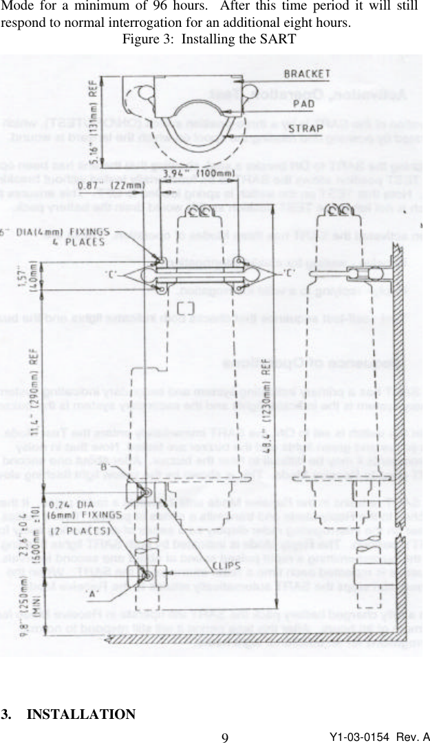
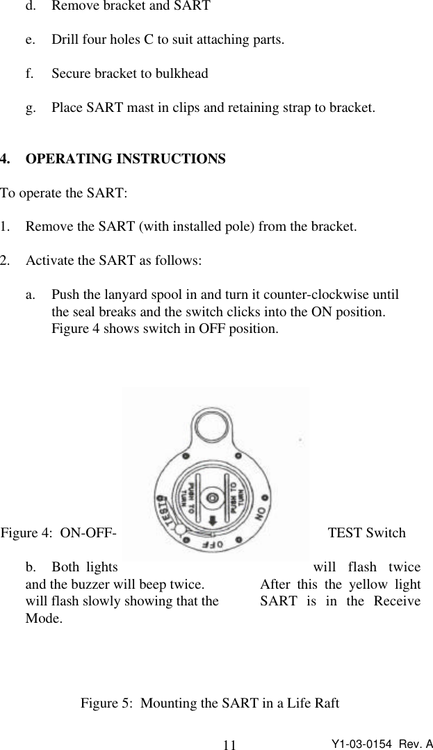
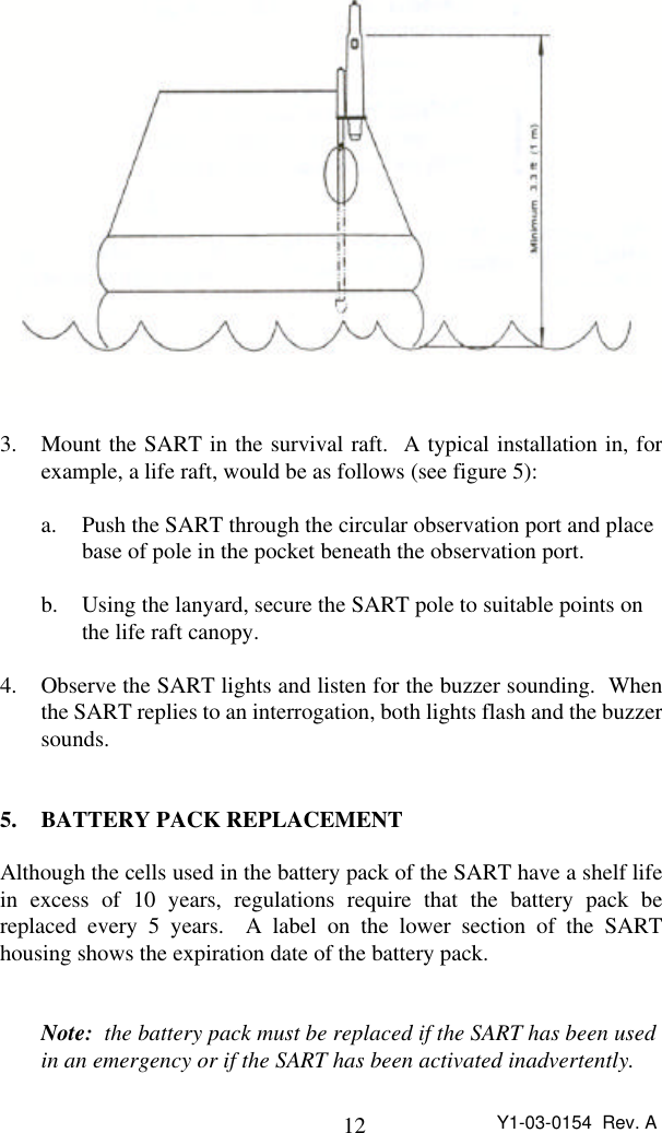
ACR Electronics, Inc. Search and Rescue Transponder Y1 03 0154

Product Manual

1Y1-03-0154  Rev. APRODUCTPRODUCTSUPPORTSUPPORTMANUALMANUALY1-03-0154Rev. APathfinder 2Search and Rescue TransponderProduct No. 2708 ACR Electronics, Inc.5757 Ravenswood RoadFort Lauderdale, Fl 33312+1(954) 981-3333 • Fax +1 (954) 983-5087http://www.acrelectronics.comEmail: Info@acrelectronics.com
2Y1-03-0154  Rev. A
3Y1-03-0154  Rev. A
4Y1-03-0154  Rev. AIMPORTANT NOTICETHE SART IS A KEY ELEMENT IN YOUR SHIP’S SURVIVALSYSTEM; ITS PROPER OPERATION IN AN EMERGENCY DE-PENDS ON THE CORRECT INSTALLATION OF THE UNIT,REGULAR MAINTENANCE AND A KNOWLEDGE OF THEMETHODS OF OPERATION OF THE SART.This manual contains important information about−  restrictions in the use of SARTs,−  the correct installation of the unit,−  the necessary maintenance and care, and−  methods of operation of the SART in an emergency.It is important that this manual be read and its contend understood beforeattempting to install or operate the SART.Keep this manual as a reference for the proper maintenance and opera-tion of the SART.If additional information is required or if problems are experienced,please contact an authorized dealer or:ACR Electronics, Inc.5757 Ravenswood RoadFt. Lauderdale, Fl  33312Tel.  (954) 981-3333Fax. (954) 983-5087NOTICE TO PURCHASERS, OWNERS AND USERS:Purchasers, owners and other users of the SART use the device at theirown risk.  In no case shall ACR Electronics, Inc. be liable for anyconsequential or incidental damages, for breach of warranty, express orimplied, or for any other reason.
5Y1-03-0154  Rev. ATable of Contents1Introduction ...............................................................32Using the SART ........................................................42.1 General ...........................................................42.2 Activation, Operation, Test.............................52.3 Sequence of Operations ..................................53Installation.................................................................74Operating Instructions ............................................... 85Battery Pack Replacement.........................................96Self-test...................................................................... 97Routine Maintenance...............................................108Note on Serial Number............................................ 119Technical Specification ...........................................129.1 General .........................................................139.2 Antenna.........................................................139.3 Transmitter....................................................149.4 Receiver........................................................159.5 Battery ..........................................................169.6 Environmental............................................... 179.7 Physical.........................................................1810 Warranty..................................................................19Figure 1: Typical SART Response Signal...................... 3Figure 2: SART - Outline Drawing................................4Figure 3: Installing the SART ........................................6Figure 4: ON-OFF-TEST Switch...................................8Figure 5: Mounting the SART in a life raft....................9Figure 6: Serial Number Grid.......................................121.0 INTRODUCTION
6Y1-03-0154  Rev. AThe SART is a Search and Rescue Transponder that provides locationinformation to search radars operating in the X-band (9.2 - 9.5 GHz).Once activated the SART detects the radar signal of the search craft andsends a series of response pulses to the search radar of the search craftthat causes a series of 12 equally spaced arcs to appear on the radardisplay (See Figure 1).  The arcs indicate the direction to the SARTlocation.  The rescue craft follows the direction shown and proceeds tothe SART.To achieve the maximum useful range the SART must be mounted atleast 3.3 feet (1 M) above sea level and the rescue craft antenna must be50 feet (15 m) above sea level.  Increasing the height of the SARTantenna will increase the range.  For example, lashing the SART to thetop of a pole or an oar in the survival craft will increase the height andthus the range.The International Maritime Organization (IMO) requires all vessels ofmore than 300 GRT to carry at least one SART and vessels 500 GRT andover must carry at least two SARTs.Figure 1: TypicalSART Re- sponse Signal
7Y1-03-0154  Rev. A2. USING THE SART2.1 GeneralInstallation and use of the SART does not require special training.Normally, the SART will be mounted on a bulkhead using the bracketand clips provided.  In an abandon ship situation, remove the SART fromthe bracket and take it to the survival craft.  The next step is to activatethe SART and install it in the survival craft.Figure 2: SART -Outline Drawing
8Y1-03-0154  Rev. A2.2 Activation, Operation, TestActivation of the SART is by a three-position switch (ON/OFF/Test),which is operated by pushing and rotating the spool on which the lanyardis wound.Switching the SART to ON breaks a seal, showing that the unit has beenoperated.  The TEST position allows the SART to be functionally testedwithout breaking the seal.  Note that TEST on the switch is spring loadedto OFF.  This ensures the switch is not left in the TEST position as thiswould drain the battery pack.When activated the SART has three Modes of operation.  These are:Receive - waiting for a valid interrogation.Reply -  replying to a valid interrogationTest -  self-test sequence that checks both indicator lights and the buzzer.2.3 Sequence of OperationsThe SART has a primary indicating system and secondary indicatingsystem.  The primary system is the indicator lights and the secondarysystem is the buzzer.When the switch is set to ON, the SART immediately enters the TestMode.  Here both yellow and green lights and the buzzer are tested.  Notethat in noisy environments it may be difficult to hear the buzzer.  Afterabout one second the SART goes to Receive Mode.  This is shown by theyellow light flashing slowly.The SART remains in the Receive Mode until it detects a radar pulse.  Itthen switches to the Reply  Mode and transmits a series of pulses.  Thesepulses will appear on the interrogating radar display as a series of arcsleading away from the SARTs position.  The Reply Mode is indicated byboth SART lights flashing rapidly and the buzzer emitting a rapid pulsedsound at about one second intervals.  This sequence is repeated each timea radar interrogates the SART.  When the interrogation stops the SARTautomatically returns to the Receive Mode.With a fully charged battery pack the SART will operate in Receive
9Y1-03-0154  Rev. AMode for a minimum of 96 hours.  After this time period it will stillrespond to normal interrogation for an additional eight hours.Figure 3:  Installing the SART3. INSTALLATION
10 Y1-03-0154  Rev. AIn addition to the SART and 3.3 feet (1 m) pole, a mounting bracket forthe body and two rubber clips for the pole are supplied.  The equipmentdoes not include mounting hardware for the bracket and the clips, asthese will depend on the bulkhead material and its thickness.  Bracketand clip mounting holes and SART mounting details are shown in Figure3.To install SART:1. Remove SART from its packaging and check for shipping damage.2. Perform the SART test (see Self-test Procedure on page xx).3. Remove the two halves of pole and attaching parts from packaging and assemble to SART as follows:a. Screw upper pole to lower pole.  Tighten using suitable wrenches.b. Push the upper pole into the pole holder on the SART andsecure using the plain washer and 6 mm lockrut supplied..4. Select a position for SART Mounting allowing sufficient space for the assembled pole.Note:  The SART contains magnetic material.  Ensure that the position that you select is at least 7 feet (2m) away from compassinstallations.5. Drill holes A and B to dimensions shown on Figure 3.  Hole Bshould be at least 3 feet above deck.6. Place clips in position and secure them to bulkhead.7. Mount SART on bulkhead as follows (see figure 3):a. Insert SART pole into clips fitted in step 6.b. Position bracket above stepped part of  SART casing.c. Mark position of four bracket fixing holes C.
11 Y1-03-0154  Rev. Ad. Remove bracket and SARTe. Drill four holes C to suit attaching parts.f. Secure bracket to bulkheadg. Place SART mast in clips and retaining strap to bracket.4. OPERATING INSTRUCTIONSTo operate the SART:1. Remove the SART (with installed pole) from the bracket.2. Activate the SART as follows:a. Push the lanyard spool in and turn it counter-clockwise until the seal breaks and the switch clicks into the ON position.Figure 4 shows switch in OFF position.Figure 4:  ON-OFF- TEST Switchb. Both lights will flash twiceand the buzzer will beep twice.   After this the yellow lightwill flash slowly showing that the  SART is in the ReceiveMode.Figure 5:  Mounting the SART in a Life Raft
12 Y1-03-0154  Rev. A3. Mount the SART in the survival raft.  A typical installation in, forexample, a life raft, would be as follows (see figure 5):a. Push the SART through the circular observation port and place base of pole in the pocket beneath the observation port.b. Using the lanyard, secure the SART pole to suitable points on the life raft canopy.4. Observe the SART lights and listen for the buzzer sounding.  Whenthe SART replies to an interrogation, both lights flash and the buzzersounds.5. BATTERY PACK REPLACEMENTAlthough the cells used in the battery pack of the SART have a shelf lifein excess of 10 years, regulations require that the battery pack bereplaced every 5 years.  A label on the lower section of the SARThousing shows the expiration date of the battery pack.Note:  the battery pack must be replaced if the SART has been used in an emergency or if the SART has been activated inadvertently.
13 Y1-03-0154  Rev. ACaution:   The battery pack CANNOT be recharged; attempts to recharge the battery pack could result in an explosion.Replacement at the SART battery pack must be performed by XXXXXXor by a authorized dealer; the cost of this replacement is the responsibil-ity of the owner.6. SELF TESTPlease note the TEST position on the SART is spring loaded to OFF andcannot be left in the TEST position.To carry out a self-test:Warning:  Keep Test time to a minimum as the SART is in Receive Mode and will respond to any X-bad radar transmission in the vicinity.  In addition, the longer the test the greater the drain on the battery pack.Note:  The SART must be tested on a monthly basis.1. Push switch in and turn against the spring to the TEST position.2. Check that both lights flash rapidly and buzzer emits a rapid pulsed sound at about one second intervals.3. After this the yellow light flashes slowly showing that the SART is in the Receive Mode.Note:  It is possible, when testing the SART, that it will be activated by an operating radar.  If this is the case both lights will flash rapidly and the buzzer will emit a rapid pulsed sound showing that SART is in the Reply Mode.  If this does happen then release theswitch.4. On completion of test, release the switch and check that it returns toOFF.Note:  If the lights do not come on the battery pack voltage may below or the SART may be defective.  Contact ACR Electronics, Inc.or an authorized dealer.
14 Y1-03-0154  Rev. A7. ROUTINE MAINTENANCEEvery month, carry out a self-test on the SART and check that batterydate has not expired.8. NOTE ON SERIAL NUMBERThe serial number on the SART is indicated by erased numbers on a grid.Read the grid from left to right.  See figure 6.  The serial number shownin Figure 6 is 435719.0    0    0    0    0    01    1    1    1          12    2    2    2    2    23          3    3    3    3      4    4    4    4    45    5          5    5    56    6    6    6    6    67    7    7          7    78    8    8    8    8    89    9    9    9    9Figure 6:  Serial Number Grid9. TECHNICAL SPECIFICATIONS9.1 General
15 Y1-03-0154  Rev. AMeets the requirements of: Global Maritime Distress and Safety Systems.  (GMDSS) according to IMO amendment to chap 111 of the 1974 SOLAS Convention, as well as part 80 of the FCC Rules.International type approval inaccordance with: IEC 1097-1 1992, I-ETS 300 151Designed to meet: RTCM Paper111-92/SC113-36(Ninth Draft SART Standard)Frequency: 9.2 GHz to 9.5 GHz9.2 AntennaPolarization: HorizontalAzimuth beam width: Omni-directional within 2 dBVertical beam width: ± 12.5°9.3 TransmitterResponse delay: 0.5 µsForward sweep time: 7.5 µs ± 1.0 µsReturn sweep time: 0.4 µs ±  0.1 µsPower output 400 mW EIRP9.4 ReceiverEffective sensitivity: -50 dBm
16 Y1-03-0154  Rev. A9.5 BatteryReceive mode operation: 96 hours minimumReply  mode operation: 8 hours continuous while beinginterrogated by an X-band radar with a pulse repetition frequency of 1 kHz (at extreme temperature).Battery Life: 5 years9.6 EnvironmentalOperating temperature: -4 F to + 131 F (-20 C to +55 C)Storage temperature: -22 F to +140 F (-30 C to +65 C)9.7 PhysicalLength: 18 in (459 mm) excluding poleDiameter: 3.5 in (90 mm) mid bodyWeight: 4.4 lbs (2 kg) including pole10. WARRANTYThe SART is guaranteed by the manufacturer to be free of defects inmaterials and workmanship for a period of one year from the date of theoriginal purchase.  This warranty is extended only to the original pur-
17 Y1-03-0154  Rev. Achaser of the unit.During the warranty period the manufacturer will repair or, at themanufacturer’s option, replace a defective unit at no cost to the owner ofthe SART for materials and labor.  Transportation charges are theresponsibility of the owner of the SART.  The unit must be packagedcorrectly and shipped prepaid to the manufacturer or an authorizedservice center; it will be returned via collect shipping.The warranty is void if the unit has been damaged through accident,misuse, improper installation, or during transportation.  The warranty isalso void if the security seal on the SART has been broken.The liability of the manufacturer shall be limited to the repair orreplacement of a defective unit during the warranty period.  The manu-facturer shall not be liable for injuries or damages arising from thehandling, possession or use of this product by the purchaser or otherswho obtain it through the purchaser.For full and complete warranty language the owner is referred to thewarranty card provided with the SART.  To validate this warranty, theenclosed warranty card must be completed and mailed before putting theunit into service.
18 Y1-03-0154  Rev. ANOTES
19 Y1-03-0154  Rev. ANOTES
20 Y1-03-0154  Rev. A

Navigation menu