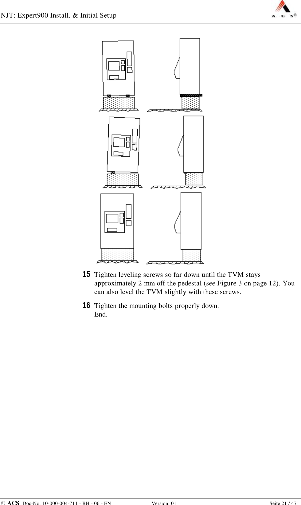
ACS Solutions Switzerland 800-0001-04-NJ Ticket Vending Machine User Manual NVIFIR03
ACS Solutions Switzerland Ltd. Ticket Vending Machine NVIFIR03
UserManual.wiki
>
ACS Solutions Switzerland
>
800 0001 04 NJ User Manual
User Manual
Navigation menu
Upload a User Manual
Namespaces
Wiki Guide
HTML
PDF
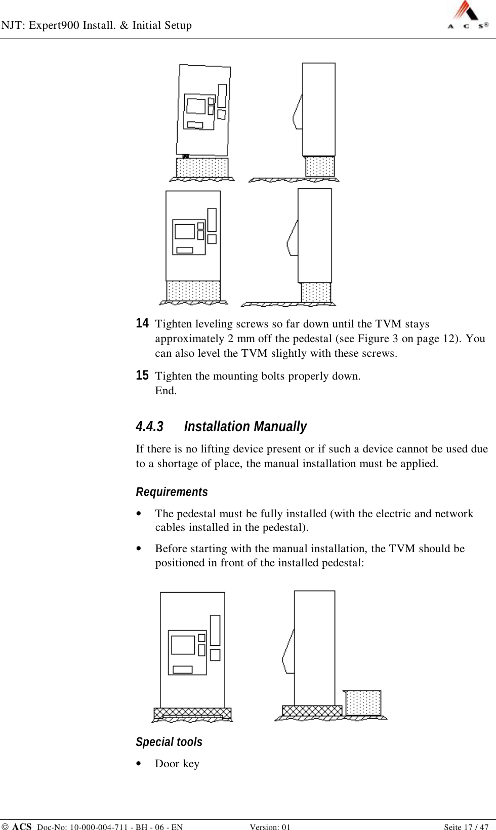
Info
Views
User Manual
Discussion / Help
Navigation