ACS Solutions Switzerland 800-0076 Ticket Vending Machine FVD Expert 9100 US User Manual SP 10 000 006 785 E00 04 000x
ACS Solutions Switzerland Ltd. Ticket Vending Machine FVD Expert 9100 US SP 10 000 006 785 E00 04 000x
Contents
- 1. UserManual.pdf
- 2. UserManualSafetyInstructions.pdf
UserManual.pdf

FVD Expert
Specification
HW Technical Description
Version 1-4
November 15, 2012
9100 US

©2012 Xerox Corporation. All rights reserved. XEROX® and XEROX and Design® are trademarks of
the Xerox Corporation in the United States and/or other countries.
Other company trademarks are also acknowledged.
This document has been through a formal review process. To the best of our knowledge it is accurate.
ACS reserves the right to make further modifications as necessary.
This document is produced for Affiliated Computer Services, Inc. (ACS) Southeastern Pennsylvania
Transportation Authority (SEPTA) project management and cannot be reproduced or distributed to any
third party without prior written consent. No part of this document may be modified, deleted, or ex-
panded by any process or means without prior written permission from ACS.
Version History
Version Number Date Description Author
1-0 03/09/2012 Initial release Alberto Martinez
1-1 03/05/2012 Inputs ACS USA Oleg Epelbaum
1-1 06/04/2012 Response to CDM Alberto Martinez
1-2 06/07/2012 After PDR Review Jon Brezinski
1-3 15/08/2012 Divers Corrections, CRs Alberto Martinez
1-4 15/11/2012 Several updates Alberto Martinez
Preliminary Design Review Requirements
PDR Requirement Technical Specification Location
PDR 8-2 Subsection 8.3.1
PDR 8-4 Subsection 8.3.2
PDR 8-8 Subsection 8.5
PDR 8-9 Subsection 8.5
PDR 8-10 Subsection 8.6.1
PDR 8-11 Subsection 8.6.2
PDR 8-12 Subsection 8.6.2.3
PDR 8-14 Subsection 8.6.5
PDR 8-15 Subsection 8.6.7.1
PDR 8-16 Subsection 8.6.7.2
PDR 8-18 Subsection 8.7
PDR 8-21 Subsection 8.9.3

FVD Expert 9100 US Dok-Nr: 10-000-006-785 - SP - 00 - EN / Version: 04 3 / 57
©Xerox / These materials are considered confidential and proprietary!
Copyright & Revision History
The copyright to this document is owned by ACS Solutions Switzerland Ltd. All documentation is con-
fidential and must not be disclosed to third parties without the prior written consent of
ACS Solutions Switzerland Ltd. The document must not be reproduced in any way. Violation is liable
to prosecution.
The documentation describes the current status of the product design at the time of drafting or updat-
ing the document. Changes and improvements, due to advances in technology and functionality, may
be introduced without prior notice or justification.
ACS Solutions Switzerland Ltd is not liable for any indirect damages incurred by the user as a result of
using this document.
Copyright 15. Nov. 12 by ACS Solutions Switzerland Ltd
Frankenstrasse 70
CH-3018 Bern
Schweiz
Document Administration
Author(s)
Alberto Martinez
Date 15.11.2012 Language EN Original Language EN
Doc. No. 10-000-006-785 Sub. No. 00 Version 04
Document type SP Specification Format A4
Tool Microsoft Word 2003/7 Location SAP-PDM
Prepared Priska Nicole Hefti Lindenmaier
Revision History (SAP)
Vers. Description of Change
00 First edition
01-04 Several updates, layout adjustments
4 / 57 Dok-Nr: 10-000-006-785 - SP - 00 - EN / Version: 04 FVD Expert 9100 US
©Xerox / These materials are considered confidential and proprietary!
Table of contents
1 About this document .................................................................... 8
1.1 Introduction ............................................................................................................... 8
1.2 Audience ................................................................................................................... 8
1.3 Related Documents .................................................................................................. 8
1.4 Subsystems Overview .............................................................................................. 9
1.5 Expert 9100 US Common Functionalities ............................................................... 10
2 Components .............................................................................. 11
2.1 Fare Vending Device — Full Function, Cashless ................................................... 11
2.2 Block Diagram......................................................................................................... 14
2.3 Housing ................................................................................................................... 15
2.4 Pedestal .................................................................................................................. 17
2.5 Lock Arrangement .................................................................................................. 18
2.5.1 Overview .................................................................................................. 18
2.5.2 Lock Plan ................................................................................................. 19
2.5.3 Door Lock Mechanism ............................................................................. 20
2.6 Human Machine Interface ....................................................................................... 21
2.6.1 Display-Touch-Module ............................................................................ 21
2.6.2 Output Tray .............................................................................................. 23
2.7 Coin Handling System RS28.7-1 ............................................................................ 24
2.7.1 Overview .................................................................................................. 24
2.7.2 Coin Insertion Unit ................................................................................... 26
2.7.2.1 Coin Insertion Slot (FVD Door) ................................................ 26
2.7.3 Coin Verifier Unit ..................................................................................... 27
2.7.4 Coin Drum Block...................................................................................... 28
2.7.5 Coin Drum ............................................................................................... 28
2.7.5.1 Cash Acceptance ..................................................................... 28
2.7.5.2 Cash Return ............................................................................. 29
2.7.5.3 Drum Function ......................................................................... 30
2.7.6 Coin Vault ................................................................................................ 31
2.7.7 Bulk Coin Storage Unit ............................................................................ 32
2.8 Banknote Recycler .................................................................................................. 33
2.8.1 Banknote Recycler CashCode ................................................................ 33
2.8.1.1 CashCode Parameters ............................................................ 34
2.9 Electronic Transfer of Funds-Point of Sale ............................................................. 35
1.1.1 PIN Pad and LCD Display ....................................................................... 35
2.9.1 Card Reader ............................................................................................ 37
2.9.2 Card Open Payment Contactless Reader ............................................... 38
2.10 Card Dispenser Unit ............................................................................................... 39
2.10.1 Overview .................................................................................................. 39
2.10.2 Card Transport Unit ................................................................................. 39
2.10.3 Card Dispenser with Card Magazine....................................................... 40
2.10.4 Weight ..................................................................................................... 40
2.11 Card Access Module ............................................................................................... 41
2.12 Printer System ........................................................................................................ 42
2.12.1 Overview .................................................................................................. 42
2.12.2 Magnetic Media Swipe Reader AP5200MC Printer ................................ 42
2.12.3 Receipt Printer AP4200 ........................................................................... 43
2.12.4 Paper ....................................................................................................... 43
2.13 Control Electronics .................................................................................................. 44
FVD Expert 9100 US Dok-Nr: 10-000-006-785 - SP - 00 - EN / Version: 04 5 / 57
©Xerox / These materials are considered confidential and proprietary!
2.13.1 Overview .................................................................................................. 44
2.13.2 Main Control Unit 4.0 Technical Data ..................................................... 45
2.13.3 Backup Functionality ............................................................................... 45
2.13.4 Operating System/Software .................................................................... 45
2.14 Power Interfaces ..................................................................................................... 46
2.15 Power Supply .......................................................................................................... 46
2.16 X-Bus Device .......................................................................................................... 47
2.17 Main Failure ............................................................................................................ 47
2.18 AC/DC Converter — Main Control Unit Supply ...................................................... 48
2.19 Battery ..................................................................................................................... 49
2.20 Service Plug ............................................................................................................ 50
2.21 Siren ........................................................................................................................ 50
2.22 Communication Interfaces ...................................................................................... 51
2.22.1 NB1600-Wireline Functions ..................................................................... 51
2.22.2 NB1600-LTE Wireless Router — Optional .............................................. 52
2.22.3 Antenna ................................................................................................... 53
2.23 Loudspeaker and Connector for Headphone Audio Amplifier ................................ 54
2.24 Service Panel .......................................................................................................... 55
1.2 Dust Cover .............................................................................................................. 56
3 Norms and Standards ................................................................ 57
3.1 Operational Conditions ........................................................................................... 57
6 / 57 Dok-Nr: 10-000-006-785 - SP - 00 - EN / Version: 04 FVD Expert 9100 US
©Xerox / These materials are considered confidential and proprietary!
List of figures
Figure 2-1: FVD Expert 9100 US Overview .......................................................................................... 11
Figure 2-2: Expert 9100 US (Indicative Only, in mm) ............................................................................ 15
Figure 2-3: FVD Door Opening in mm ................................................................................................... 15
Figure 2-4: Contact Switches on the Housing ....................................................................................... 18
Figure 2-5: Locking System on Door Side ............................................................................................. 20
Figure 2-6: Locking System on Housing Side ..................................... Error! Bookmark not defined.20
Figure 2-7: Display Touch Module — Front Side .................................................................................. 22
Figure 2-8: Display Touch Module — Rear Side ................................................................................... 22
Figure 2-9: Output Tray ......................................................................................................................... 23
Figure 2-10: RS28.7-1 ........................................................................................................................... 24
Figure 2-11: Cash Flowchart Diagram — Configuration Drum Block is Only Indicative ....................... 25
Figure 2-12: Coin Insertion Unit ............................................................................................................. 26
Figure 2-13: Coin Verifier Unit ............................................................................................................... 27
Figure 2-14: Coin Drum Block ............................................................................................................... 28
Figure 2-15: Coin Drum Block Storage.................................................................................................. 28
Figure 2-16: Principle Underlying the Function of the Coin Drum ......................................................... 29
Figure 2-17: Coin Vault .......................................................................................................................... 31
Figure 2-18: Principle Underlying the Function of the BUCO ................................................................ 32
Figure 2-19: CashCode BNR ................................................................................................................. 33
Figure 2-20: PIN Pad ............................................................................................................................. 36
Figure 2-21: VeriFone Card Reader ...................................................................................................... 37
Figure 2-22: ViVOpay Kiosk .................................................................................................................. 38
Figure 2-23: Card Dispenser Unit .......................................................................................................... 39
Figure 2-24: Card Dispenser with Card Magazine ................................................................................ 40
Figure 2-25: Card Magazine Weight...................................................................................................... 40
Figure 2-26: CAM Reader/Writer and Antenna Switch Module ............................................................. 41
Figure 2-27: Receipt Printer — AP 5200MC ......................................................................................... 42
Figure 2-28: Receipt Printer — AP 4200 ............................................................................................... 43
Figure 2-29: MCU 4.0 ............................................................................................................................ 44
Figure 2-30: Power Manager ................................................................................................................. 46
Figure 2-31: AC/DC Converter .............................................................................................................. 48
Figure 2-32: Battery Module .................................................................................................................. 49
Figure 2-33: Service Plug ...................................................................................................................... 50
Figure 2-34: Siren 50
Figure 2-35: NB1600-Wireline ............................................................................................................... 51
Figure 2-36: NB1600-LTE Wireless Router ........................................................................................... 52
Figure 2-37: Antenna ............................................................................................................................. 53
Figure 2-38: Service Panel .................................................................................................................... 55
Figure 2-39: Dust Coverl ....................................................................................................................... 56
Figure 2-40: Dust Cover (technical View) .............................................................................................. 56
FVD Expert 9100 US Dok-Nr: 10-000-006-785 - SP - 00 - EN / Version: 04 7 / 57
©Xerox / These materials are considered confidential and proprietary!
List of tables
Table 1-1: Subsystems Overview ............................................................................................................ 9
Table 2-1: FVD Expert 9100 US — Hardware Shown in Figure ........................................................... 12
Table 2-2: FVD Expert 9100 US — Hardware Not Shown in Figure ..................................................... 13
Table 2-3: Housing Datasheet ............................................................................................................... 16
Table 2-4: Pedestal Datasheet .............................................................................................................. 17
Table 2-5: Lock Arrangement ................................................................................................................ 18
Table 6 – Lock plan FVD ....................................................................................................................... 19
Table 7 – Lock plan FVD pedestal ........................................................................................................ 19
Table 8 – Lock plan related to money containers .................................................................................. 19
Table 2-9: HMI Datasheet Extraction .................................................................................................... 22
Table 2-10: Drum Configuration Datasheet Extraction.......................................................................... 29
Table 2-11: Configurable Drum Assignment ......................................................................................... 30
Table 2-12: Coin Vault Datasheet Extraction ........................................................................................ 31
Table 2-13: BUCO — Initial Configuration and Capacity ...................................................................... 32
Table 2-14: CashCode Datasheet Extraction ........................................................................................ 34
Table 2-15: VeriFone Vx700 Datasheet Extraction ................................................................................ 36
Table 2-16: VeriFone SCR710 Datasheet Extraction............................................................................ 37
Table 2-17: ViVOpay Kiosk Datasheet Extraction ................................................................................. 38
Table 2-18: AP5200MC — Datasheet Extraction .................................................................................. 43
Table 2-19: AP 4200 Paper ................................................................................................................... 43
Table 2-20: SBC and COMO Information .............................................................................................. 44
Table 2-21: MCU 4.0 — Datasheet Extraction ...................................................................................... 45
Table 2-22: MCU 4.0 — Datasheet Extraction ...................................................................................... 46
Table 2-23: Data of the Integrated UPS — Sheet Extraction ................................................................ 46
Table 2-24: AC/DC Converter — Datasheet Extraction for MCU Supply.............................................. 48
Table 2-25: Battery – Datasheet Extraction .......................................................................................... 49
Table 2-26: Siren — Sheet Extraction ................................................................................................... 50
Table 2-27: NB1600-Wireline — Sheet Extraction ................................................................................ 52
Table 2-28: NB1600-LTE Wireless Router — Sheet Extraction ............................................................ 53
Table 2-29: Service Panel — Sheet Extraction ..................................................................................... 55
Table 3-1: Norms and Standards .......................................................................................................... 57
Table 3-2: Environment and Climate ..................................................................................................... 57

8 / 57 Dok-Nr: 10-000-006-785 - SP - 00 - EN / Version: 04 FVD Expert 9100 US
©Xerox / These materials are considered confidential and proprietary!
1 About this document
1.1 Introduction
This document specifies the configuration and technical description of the Expert 9100 US
Fare Vending Device (FVD) for the SEPTA New Payment Technologies (NPT) system.
NOTE:
Features not listed in the table or explicitly defined in the Technical Specification are exclud-
ed.
1.2 Audience
The intended audience of this document includes the SEPTA NPT project members.
1.3 Related Documents
This Fare Vending Device Hardware Specification document is part of a larger series, which
includes:
Manuals
[1] Fare Vending Device Overview – 10-000-00x-xxx E00 BH
[2] Fare Vending Device Functional Specification – 10-000-00x-xxx E00 BH
[3] Fare Vending Device Compliance Matrix – 10-000-00x-xxx E00 BH

FVD Expert 9100 US Dok-Nr: 10-000-006-785 - SP - 00 - EN / Version: 04 9 / 57
©Xerox / These materials are considered confidential and proprietary!
1.4 Subsystems Overview
The FVD Expert 9100 US for the SEPTA NPT project consists of the ticket vending ma-
chines according to Table 1-1: Subsystems Overview.
Full Function Cashless
Subsystem/Functions FVD FVD
Type Stationary Stationary
Base Expert 9100 US Expert 9100 US
Issue Smart Media Smart Media Dispenser Mod-
ules Smart Media Dispenser Modules
Issue MMSR AP5200MC AP5200MC
Issue receipts AP4200 AP4200
Accept coins RS28.7-1
Escrow and change in coins 5 fully equipped drums plus
2 dummies
Escrow coins Yes
BUCOs Yes
Accept banknotes B2B300XE
Escrow banknotes B2B300XE
Recycle banknotes B2B300XE
Accept credit and debit cards EFT Solution EFT Solution
Swipe reader for magnetic
stripe — MMSR Yes Yes
Front illumination Yes Yes
Heating Yes Yes
Communication Via LAN Via LAN
Information panel No Yes
Set for internal housing illumi-
nation Yes Yes
Audio amplifier and loud-
speaker Yes Yes
Electronic control unit
(MCU4.0 with 2GB RAM, in-
cluding COMO and licensed
Windows)
Yes Yes
EFT-PoS terminal Yes Yes
UMTS antenna (only for GSM
connected devices) Yes Yes
Viper Yes Yes
Siren Yes Yes
Dry contact Yes Yes
Power manager with tempera-
ture sensor Yes Yes
Table 1-1: Subsystems Overview
10 / 57 Dok-Nr: 10-000-006-785 - SP - 00 - EN / Version: 04 FVD Expert 9100 US
©Xerox / These materials are considered confidential and proprietary!
1.5 Expert 9100 US Common Functionali-
ties
The FVD Expert 9100 US is based on the Expert 9x00 Ticket Vending Machine family and
provides the following common functionalities (depending on the type of configuration):
• Selecting the defined products on the touch-screen display
• Adding value or a product onto a transit account linked to the General Purpose Re-
loadable (GPR) card issuing receipts
• Paying with banknotes
• Returning banknotes
• Encoding and printing magnetic fare media from fan-folded Magnetic Media Swipe
Reader (MMSR) stock
• Dispensing GPR cards from stackers
• Paying with credit and debit cards — Electronic Transfer of Funds (EFT) module
• Paying with coins
• Returning coins
FVD Expert 9100 US Dok-Nr: 10-000-006-785 - SP - 00 - EN / Version: 04 11 / 57
©Xerox / These materials are considered confidential and proprietary!
2 Components
The following subsections include information on the Expert 9100 US ticket vending machine
components.
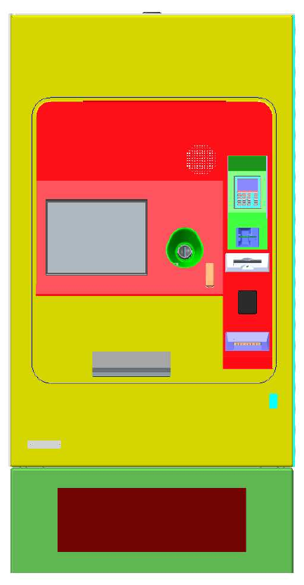
2.1 Fare Vending Device — Full Function,
Cashless
This subsection describes the general characteristics of the Expert 9100 US.
Figure 2-1: FVD Expert 9100 US Overview

12 / 57 Dok-Nr: 10-000-006-785 - SP - 00 - EN / Version: 04 FVD Expert 9100 US
©Xerox / These materials are considered confidential and proprietary!
Name Description
1 Cabinet
The cabinet protects the interior of the Expert 9100 US and the
modules.
An option for a two sides and roof protection against forced intru-
sion is available.
2 Door
The door gives access to the modules.
The four door hinges, invisible from outside, are on the left-hand
side in order to open the door from right to left up to a maximum
angle of 128°. The conductive seal provides the necessary EMC
connection.
The front of the door has:
• Pictograms — symbols for passenger instructions —as pro-
vided by SEPTA
• Braille and raised text instructions for visually impaired pas-
sengers — as provided by SEPTA
3 Pedestal The closed pedestal provides the mechanical and grounding inter-
face between the floor and the cabinet.
4 Banner Customer-specific printed banner — optional.
5 Touch-Screen Display
15-inch LCD-TFT display with touch screen.
It allows the passenger, as well as the service personnel, to inter-
act with the FVD Expert 9100 US.
6 EFT-PoS Module
The EFT-Point of Sale (PoS) module — composed of frame, pri-
vacy protection, dip reader, contactless reader and PIN Pad —
allows the passenger to pay by credit or debit card.
7 Output Tray
Receipts, issued fare media — Smart Media — and change in
coins fall into this receptacle equipped with an LED, which can be
illuminated during this process. It has a transparent flap that keeps
the issued items from falling out and protects the output tray from
dust.
8 Coin Handling System
Module
The self-replenishing coin handling system RS28.7-1 allows the
passenger to pay with coins. It is capable of validating up to 15
different coins and works according to the last in, first out (LIFO)
principle. This prevents any type of money laundering.
9 BNR
The BNR CashCode B2B300XE allows the passengers to pay
with banknotes.
The banknote vault has a capacity of 1,000 banknotes.
10 Audio Amplifier and
Loudspeaker
The audio amplifier and loudspeaker will support the passenger
during sales.
Table 2-1: FVD Expert 9100 US — Hardware Shown in Figure

FVD Expert 9100 US Dok-Nr: 10-000-006-785 - SP - 00 - EN / Version: 04 13 / 57
©Xerox / These materials are considered confidential and proprietary!
Name Description
Printer Module for MMSR The thermal printer module for MMSR, AP5200MC, is used to print,
encode and issue fan-folded MMSR.
GPR Dispenser Module There is space for up to 2 Smart Media dispenser modules — maga-
zine with encoding and transport unit.
Paper Printer Module The thermal paper printer module, such as AP4000, is used to print
and issue receipts for passengers and service personnel.
Communication Module
In the standard version, a modular coupler allows the connection to
the LAN. There is an option to configure the FVD Expert 9100 US with
a wireless communication module. The wireless communication mod-
ule allows communication between the FVD and the backend or the
bank clearing house to be established in case of an EFT-POS pay-
ment over GPRS, EDGE, UMTS or HSDPA.
MCU Module
The MCU 4.0 — controlling and supervising the FVD Expert 9100 US
— consists of an SBC, a COMO, a mass storage device and a CF
card as backup media.
Heating The FVD Expert 9100 US is equipped with a heater and with tempera-
ture monitoring.
Headphone Connector A headphone connector — 3.5-mm mono jack — is installed on the
FVD front panel..
Table 2-2: FVD Expert 9100 US — Hardware Not Shown in Figure
14 / 57 Dok-Nr: 10-000-006-785 - SP - 00 - EN / Version: 04 FVD Expert 9100 US
©Xerox / These materials are considered confidential and proprietary!
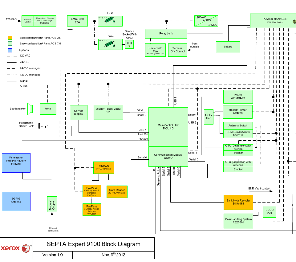
2.2 Block Diagram
15 / 57 Dok-Nr: 10-000-006-785 - SP - 00 - EN / Version: 04 FVD Expert 9100 US
©Xerox / These materials are considered confidential and proprietary!
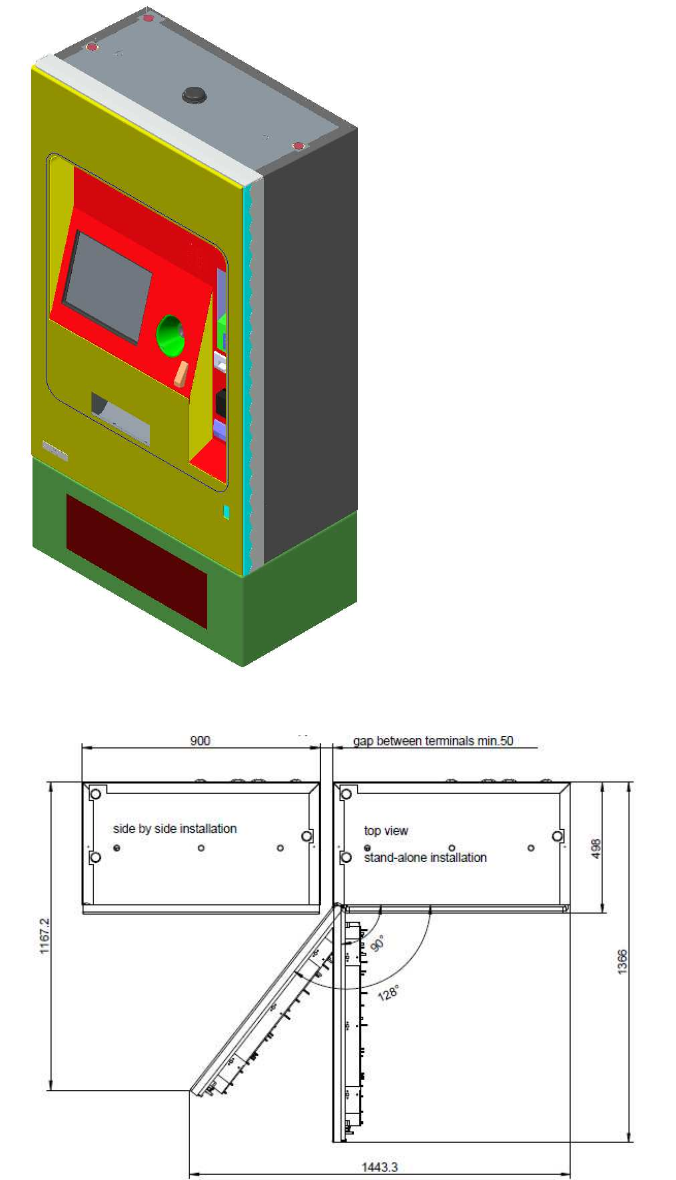
2.3 Housing
The following figures and tables provide information regarding Expert 9100 US housing.
Figure 2-2: Expert 9100 US (Indicative Only, in mm)
Figure 2-3: FVD Door Opening in mm

16 / 57 Dok-Nr: 10-000-006-785 - SP - 00 - EN / Version: 04 FVD Expert 9100 US
© Xerox / These materials are considered confidential and proprietary!
Feature Description
Key Characteristics Housing: 2 mm stainless steel, brushed
Door: 3 mm stainless steel, brushed
Dimensions H x D x W: 1423 mm x 500 mm x 900 mm, excluding pedestal
Material Stainless steel (V2A), (1.4301, AISI 304)
Fixation Housing/Pedestal The FVD housing is fixed by four M12 screws — secured with
Loctite — onto the pedestal.
Intrusion of Fluids and Objects
The specific intrusion of fluids and objects will be avoided by the
respective design of the construction (use of shutters).
Remaining fluids that enter the FVD through operation openings
will be collected and drained to the outside.
Fluids that enter and do not harden, glue or corrode will not cause
damage or interference in the FVD.
Flammability
The parts accessible from the outside of the housing unit are met-
al, glass or synthetic. These parts are flame-retardant and will only
allow minimal deformation under the impact of a 30-second flame
from a cigarette lighter.
Accessible Parts All parts accessible from the outside are mounted on the inside.
The housing has no screws that can be loosened from the outside.
Color and surface treatment Color HMI Area to be decided be SEPTA
Exposed surfaces are stainless steel with a #4 Brushed finish.
Writing/Labels/Pictograms Color RAL — to be decided with SEPTA by FDR
Coat Inside Stained and passivated
Hinges The hinge construction contains four bracket hinges that are
blind-mounted on the left-hand side.
Door Opening Brackets
The door of the FVD can be fixed mechanically in the open angle
of approximately 90, 120 and 128 degrees. The protrusion of the
door, measured from the front of the housing, is approximately:
900mm at an angle of 90 degrees
742mm at an angle of 128 degrees
Table 2-3: Housing Datasheet
NOTE
Features not listed in the table or explicitly defined in the Technical Specification are exclud-
ed.
For easy movement and installation there are three holes in the roof. After installation they
will be covered by plates with seals.
Any sharp edges have been deburred for safety reasons.

FVD Expert 9100 US Dok-Nr: 10-000-006-785 - SP - 00 - EN / Version: 04 17 / 57
©Xerox / These materials are considered confidential and proprietary!
2.4 Pedestal
The purpose of the pedestal is to:
• Simplify the installation — the power and communication cables coming from outside
terminate in it
• Provide a reliable earth connection
• Allow proper leveling of the Expert 9100 US
Feature Description
Dimensions H x D x W: 380 mm x 500 mm x 900 mm
Material Stainless steel (V4A), (1.4404, AISI 316L)
Color and surface treatment Exposed surfaces are stainless steel with a #4 Brushed finish.
Intrusion of Fluids and Objects
The specific intrusion of fluids and objects will be avoided by the
respective design of the construction.
Remaining fluids that enter the pedestal through operation open-
ings will be collected and drained to the outside.
Fluids such as soft drinks that enter and do not harden, glue or
corrode will not cause damage or interference in the pedestal.
Flammability The parts accessible from the outside are metal.
Accessible Parts
All parts that are accessible from the outside are mounted on the
inside. The pedestal has no screws that can be loosened from
the outside.
Table 2-4: Pedestal Datasheet

18 / 57 Dok-Nr: 10-000-006-785 - SP - 00 - EN / Version: 04 FVD Expert 9100 US
© Xerox / These materials are considered confidential and proprietary!
2.5 Lock Arrangement
The following subsections, figures and tables provide further information regarding the lock-
ing arrangement on the FVD.
2.5.1 Overview
The door and lock of the FVD are monitored by three contact switches: one contact mounted
at the top, one contact mounted at the bottom of the FVD door, and one lock contact. These
are directly connected to the adapter door control printed circuit boards (PCB), which gener-
ates an alarm, if necessary.
Figure 2-4: Contact Switches on the Housing
This combination allows recognizing the four states for the door shown in Table 2-5: Lock Ar-
rangement.
Switch Status Explanation
Door closed
Lock closed
Normal status of the FVD, ready for operation.
Door open
Lock open
Service status of the FVD, ready for service work to
be carried out.
Door open
Lock closed
Door has possibly been opened irregularly, possible
break-in attempt!
Door closed
Lock open
Door not closed correctly.
Table 2-5: Lock Arrangement
The FVD can interpret each of these states and trigger an appropriate message or alarm, if
necessary. The detailed FVD functional description is located in the PDR deliverable Fare
Vending Devices Functional Specifications.

FVD Expert 9100 US Dok-Nr: 10-000-006-785 - SP - 00 - EN / Version: 04 19 / 57
©Xerox / These materials are considered confidential and proprietary!
2.5.2 Lock Plan
FVD door lock and module locks will be defined in the locking plan.
Switch Status Lock No Code Key No
Housing door (Cyberlock) A Cyberlock tbd
Coin drum pull-out (release) B TH0293
Coin vault pull-out (release) B TH0293
Banknote vault pull-out (re-
lease) C Crane tbd
BUCO pull-out (release) B TH0293
Coin vault opening (cash) D TH0294
Banknote vault opening (cash) E Crane tbd
BUCO opening (cash) D TH0294
Crank key F 840.7861
Table 6 – Lock plan FVD
Switch Status Lock No Code Key No
Pedestal door G TH0295
Table 7 – Lock plan FVD pedestal
Feature Description
Pull-out (release) Allows to remove the coin / banknote vault from the FVD
Opening (cash) Allows direct access to the cash
Table 8 – Lock plan related to money containers
The RS28.7 coin drum block is provided with a spring loaded latch that has the facility to be
locked with a padlock.
The door has a 5 point locking system and a security lock (DOM half-length cylinder – sup-
plied by ACS). Once this security lock has been removed, the door can be opened using a
crank key.
20 / 57 Dok-Nr: 10-000-006-785 - SP - 00 - EN / Version: 04 FVD Expert 9100 US
© Xerox / These materials are considered confidential and proprietary!
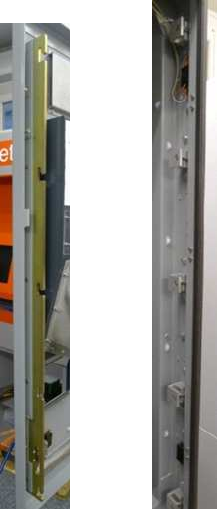
2.5.3 Door Lock Mechanism
The door lock mechanism is constructed to be robust and stable. This design is proofed and
reliable. The design has been used in the field on most frequently used sites for over 20
years.
Figure 2-5: Locking System on Door Side and Housing Side

FVD Expert 9100 US Dok-Nr: 10-000-006-785 - SP - 00 - EN / Version: 04 21 / 57
©Xerox / These materials are considered confidential and proprietary!
2.6 Human Machine Interface
This subsection contains information on the Human Machine Interface (HMI).
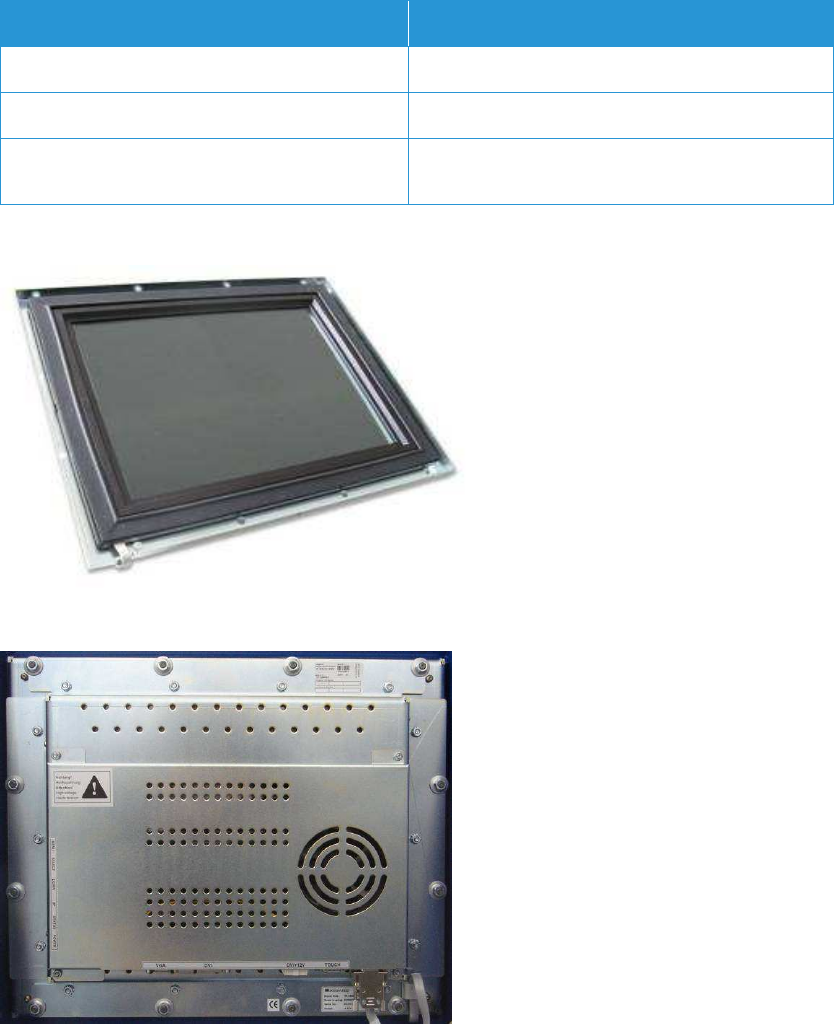
2.6.1 Display-Touch-Module
The passenger user interface represents the HMI for the passenger for all sales operations.
The information displayed on the Liquid Crystal Display (LCD) guides the passenger through
the sales process.
In order to display complex tariff structures, to simplify the passenger’s task to quickly select
a product, and to have no restrictions for future HMI adaptations, the FVD is equipped with a
touch display module. It consists of an infrared touch screen and a 15-inch LCD-Thin Film
Transistor (TFT) panel. The selection may be acknowledged by an acoustic signal — loud-
speaker.
The optical matrix touch screen consists of light emitting diodes (LED) and phototransistors
placed directly opposite each other on both the X- and Y-axes. The frame construction con-
sists of a PCB assembly carrying the optoelectronic components, which are mounted behind
a protective infrared transparent bezel. The bezel protects the electronics against any dam-
aging environmental influences.
The infrared controller activates the LEDs in sequence, forming a light-beam grid. An object
— finger placed within the grid interrupts one or more beams of light, which allows the X and
Y coordinates of the object’s position within the grid to be determined.
Infrared systems are not subject to any mechanical loading, which makes them particularly
suitable for applications that are endangered by vandalism.
Feature Description
Readability
The high brightness (600cd/m2) allows a good
readability in all light conditions. Although, as with
all available LCDs, it is preferable that they are not
under direct sunlight, as it will affect visual perfor-
mance. Brightness and contrast are manually
adjusted. The screen of the FVD has an inclination
angle of 16 degrees.
Display
Type 15-inch LCD-TFT transflective display
Visible Area 300 x 225 mm (width x height)
Resolution 1024 x 768 pixels
Colors 24 Bit — true color
Contrast 600:1
Glass specification Security glass — 7.2-mm laminated tempered
glass, antiglare edged
Filter UV light sun protection to improve readability in
unfavorable light conditions
Touch Screen
22 / 57 Dok-Nr: 10-000-006-785 - SP - 00 - EN / Version: 04 FVD Expert 9100 US
© Xerox / These materials are considered confidential and proprietary!
Feature Description
Active Operating Area 300 x 225 mm
Scanning Rate 25 frames/second
Touch Resolution Infrared touch systems can be triggered by any
object with a minimum diameter of 8.9 mm
Table 2-9: HMI Datasheet Extraction
Figure 2-6: Display Touch Module — Front Side
Figure 2-7: Display Touch Module — Rear Side
The display touch module is mounted in a way that allows for easy on-site replacement.
FVD Expert 9100 US Dok-Nr: 10-000-006-785 - SP - 00 - EN / Version: 04 23 / 57
©Xerox / These materials are considered confidential and proprietary!
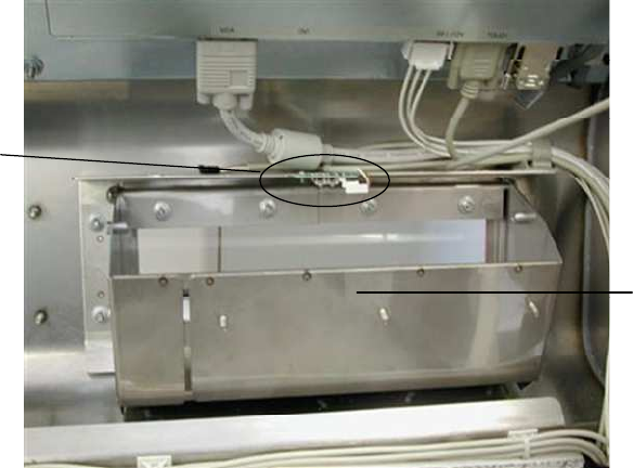
2.6.2 Output Tray
The issued GPRs and MMSRs and or returned coins — change or coins returned after a
cancelled transaction — fall into the output tray. For removal, the passenger has to push the
transparent plastic flap. During a certain time that is adjustable by software, the output tray is
illuminated by a flashing LED.
The output tray is positioned in such a way that even handicapped passengers can grab the
tickets and the change. However, it will be difficult for people with significant neuromuscular
deficiencies to use the output tray. The design prevents access to the FVD through the out-
put tray.
Ilumination
Module
Output tray
Figure 2-8: Output Tray
24 / 57 Dok-Nr: 10-000-006-785 - SP - 00 - EN / Version: 04 FVD Expert 9100 US
© Xerox / These materials are considered confidential and proprietary!
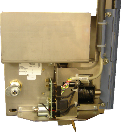
2.7 Coin Handling System RS28.7-1
The following subsections contain additional information regarding the RS28.7-1 coin han-
dling system.
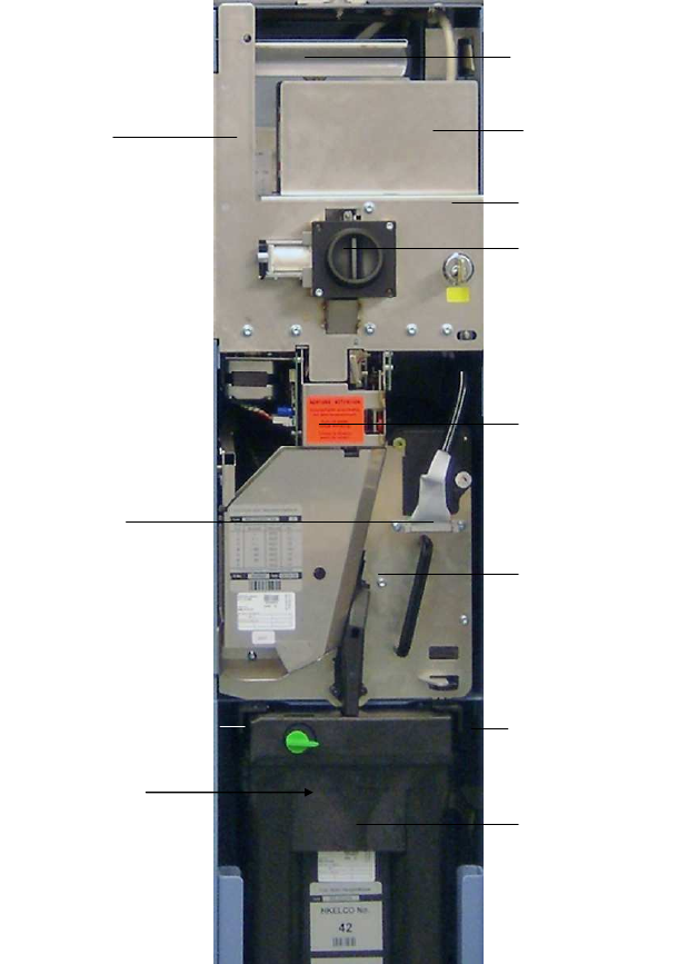
2.7.1 Overview
The RS28.7-1 is a self-replenishing/return coin handling system. It is capable of validating up
to 15 different coins and works according to the LIFO principle. This prevents any type of
money laundering in a cancelled transaction. In this case, the FVD returns inserted coins.
The accepted coins are stored in up to seven coin drums. Each coin drum is an escrow and
a self-refilling coin container. The capacity per drum is 50 coins.
RS-Chassis
Connection cable
Drum block
Control unit
Additional coin storage
unit (BUCO)
CPU
(behind cover plate)
Coin insertion unit
Plastic nozzle — the
FVD is equipped with a
rounded plastic nozzle
Coin verifier
Coin drum block
with integrated coin
drums
Coin vault interface
(behind vault)
Coin vault guide
Coin vault
Figure 2-9: RS28.7-1
FVD Expert 9100 US Dok-Nr: 10-000-006-785 - SP - 00 - EN / Version: 04 25 / 57
©Xerox / These materials are considered confidential and proprietary!
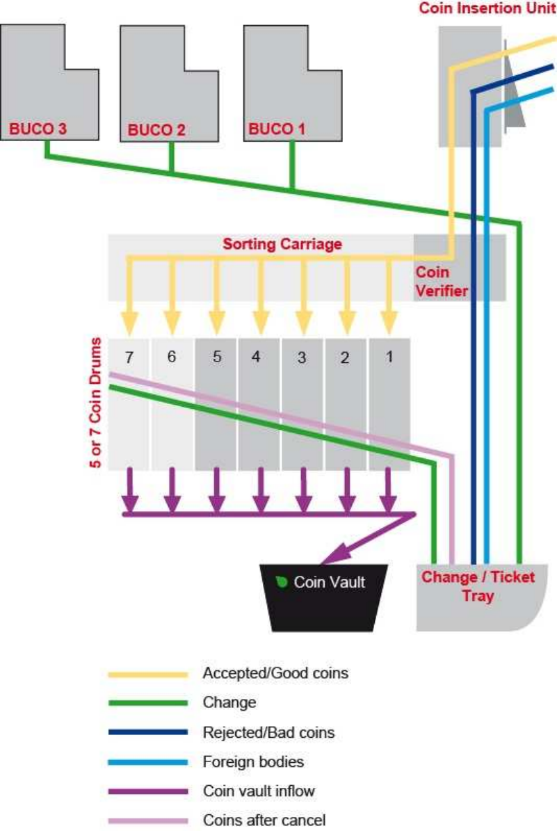
Figure 2-10: Cash Flowchart Diagram — Configuration Drum Block is Only Indicative
Two photoelectric sensors are installed in the coin insertion unit to detect inserted coins and
coin blockages. “Dummy” drums are drums that are not configured to take coins. They are
ready to be used at a later date with further configuration.
26 / 57 Dok-Nr: 10-000-006-
785
© Xerox / These materials are considered confidential and proprietary!
2.7.2 Coin
Insertion Unit
Figure 2-11
: Coin Insertion Unit
The coin insertion unit is composed of a dedicated complete door and the coin insertion unit
mechanism. The coin insertion unit is capable of handli
Together with the coin verifying unit, it influences the acceptance rate of the RS28.7
change return system.
•
If the coins are inserted at a rate slower than one coin per 1.7 seconds, the insertion flap
is opened constantly.
•
If the coins are inserted at a rate faster than one coin per 1.7 seconds, the coin insertion
unit controls the coin flow by activating the insertion flap.
•
Foreign bodies are directed straight to the output tray.
2.7.2.1 Coin Insertion
Slot (FVD Door)
T
he coin insertion unit is equipped with a dirt flap to prevent foreign objects from being i
serted into the coin insertion “nozzle.”
• Material nozzle —
thermoplastic polyester PBT
• Color — black
785
- SP - 00 - EN / Version: 04
FVD Expert 9100 US
© Xerox / These materials are considered confidential and proprietary!
Insertion Unit
: Coin Insertion Unit
The coin insertion unit is composed of a dedicated complete door and the coin insertion unit
mechanism. The coin insertion unit is capable of handli
ng the inserted coins sequentially.
Together with the coin verifying unit, it influences the acceptance rate of the RS28.7
If the coins are inserted at a rate slower than one coin per 1.7 seconds, the insertion flap
If the coins are inserted at a rate faster than one coin per 1.7 seconds, the coin insertion
unit controls the coin flow by activating the insertion flap.
Foreign bodies are directed straight to the output tray.
Slot (FVD Door)
he coin insertion unit is equipped with a dirt flap to prevent foreign objects from being i
serted into the coin insertion “nozzle.”
thermoplastic polyester PBT
-30%GF
FVD Expert 9100 US
The coin insertion unit is composed of a dedicated complete door and the coin insertion unit
ng the inserted coins sequentially.
Together with the coin verifying unit, it influences the acceptance rate of the RS28.7
-1
If the coins are inserted at a rate slower than one coin per 1.7 seconds, the insertion flap
If the coins are inserted at a rate faster than one coin per 1.7 seconds, the coin insertion
he coin insertion unit is equipped with a dirt flap to prevent foreign objects from being i
n-
FVD Expert 9100 US Dok-Nr: 10-000-006-785 - SP - 00 - EN / Version: 04 27 / 57
©Xerox / These materials are considered confidential and proprietary!
2.7.3 Coin Verifier Unit
Figure 2-12: Coin Verifier Unit shows a five-coin verifier, only indicative.
Connection plug
Drive motor for
measuring bar
Drive motor for
sorting carriage
Sorting carriage
Diameter
measuring
system
PCB with heat sink
(power stage)
Figure 2-12: Coin Verifier Unit
Coins are verified and sorted in the coin verifier unit. Optimal verification of the coin is en-
sured by precisely fixing the coin mechanically in a defined position. All the measurements
are made when the coin is static.
If a coin is judged to be good, the sorting carriage moves to the appropriate coin drum and
deposits the coin there. This means that the coin is directed from being accepted to being
stored in a completely controlled manner.
The following physical parameters must be tested:
• Diameter — mechanical measurement by "feel"
• Thickness — inductive measurement
• Eight different alloy parameters — four at the edges and four in the center
• The coin verifier unit can process the parameters of up to 15 different coins.
An individual ELCO number, or serial number, issued by the manufacturer uniquely identifies
each coin verifier.
28 / 57 Dok-Nr: 10-000-006-785 - SP - 00 - EN / Version: 04 FVD Expert 9100 US
© Xerox / These materials are considered confidential and proprietary!
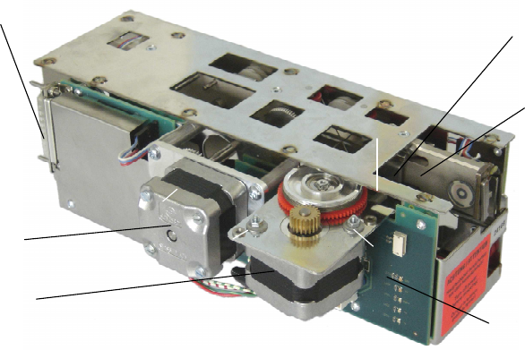
2.7.4 Coin Drum Block
The coin drum block, or change storage unit, contains seven identical coin drums. The coin
drum block is protected against unauthorized manipulation by a seal — coin vault security.
Coin channel
to the coin box
7 coin drums
Channel for change — bad
coins and foreign bodies
Print cover
Carrying handle
Seal adhesive
Figure 2-13: Coin Drum Block
2.7.5 Coin Drum
A maximum of 50 coins can be stored in each coin drum. If a sale action is aborted, the pas-
senger receives back the same coins he inserted himself. Each coin drum is coded with its
own ELCO number. It is only possible to exchange individual coin drums in the workshop. In
the field, the whole coin drum block must be exchanged.
Storage wheel
Motor
Figure 2-14: Coin Drum Block Storage
The coin drums can be refilled in the field by using a special refill function. Coins are inserted
in the coin insertion unit with the FVD door closed.
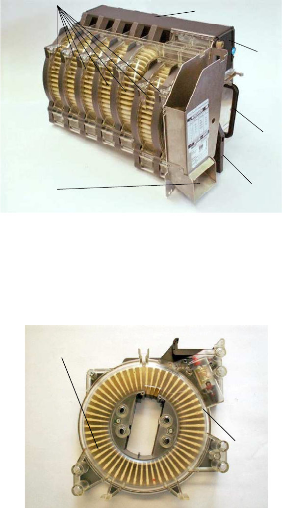
2.7.5.1 Cash Acceptance
The sorting carriage of the coin verifier moves an accepted coin to the right drum, where it is
dropped into the empty storage section of the coin drum. This causes the storage wheel to
FVD Expert 9100 US Dok-Nr: 10-000-006-785 - SP - 00 - EN / Version: 04 29 / 57
©Xerox / These materials are considered confidential and proprietary!
move one step anti-clockwise to accept the next coin. An empty section is again positioned
under the inlet slot, ready to accept the next coin.
Figure 2-15: Principle Underlying the Function of the Coin Drum
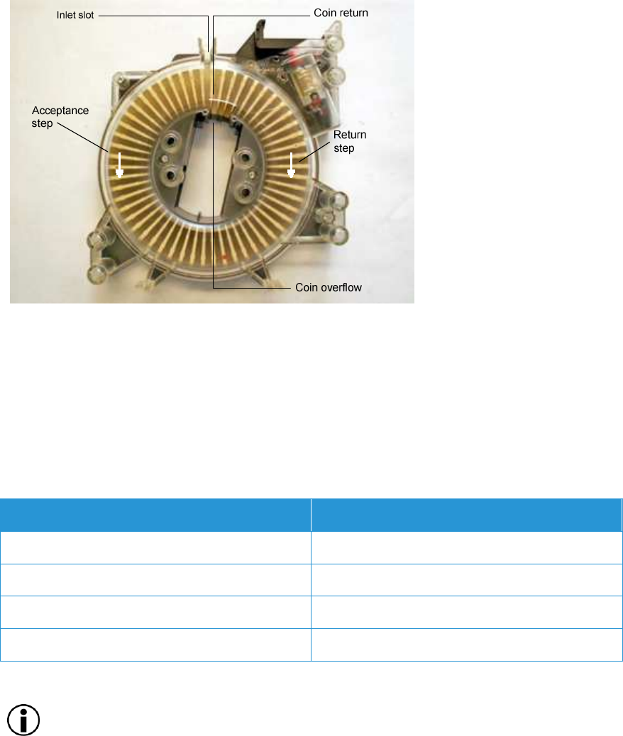
2.7.5.2 Cash Return
The storage wheel turns clockwise back one step. The last inserted coin is now positioned
under the inlet slot. Each time the wheel moves back one step, a coin falls through the return
channel. When the coin has been returned, the wheel makes an acceptance step and an
empty section is available again to store a coin.
If the drum is full, the coin above the overflow is sent through a channel into the coin vault.
Parameter Description
Max. drums per block 7
Max. coin diameter 33.5 mm
Max. coin thickness 3.4 mm
Max. coins per drum 50
Table 2-10: Drum Configuration Datasheet Extraction
NOTE
Drum position 7 is for coins with a maximum diameter of 24 mm.

30 / 57 Dok-Nr: 10-000-006-785 - SP - 00 - EN / Version: 04 FVD Expert 9100 US
© Xerox / These materials are considered confidential and proprietary!
2.7.5.3 Drum Function
• “T” — drum for one denomination only
• "f" — in front part of coin drum block
• "r" — in back part of coin drum block
• ELCO No. — Each drum is coded with an individual ELCO number, or serial number,
that is issued by the manufacturer and uniquely identifies each drum.
Drum Position Drum Function Denomination USD ELCO No.
1f T not configured
2 T 1.00
3 T 0.25
4 T 0.25
5 T 0.10
6r T 0.05
7r T not configured
Table 2-11: Configurable Drum Assignment
FVD Expert 9100 US Dok-Nr: 10-000-006-785 - SP - 00 - EN / Version: 04 31 / 57
©Xerox / These materials are considered confidential and proprietary!
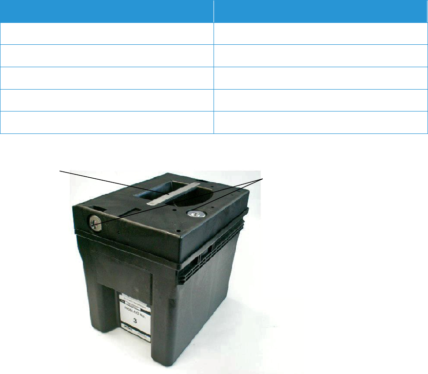
2.7.6 Coin Vault
The coin vault — volume 4.5 liters — is the final coin container, where coins coming from the
self-refilling coin drums accumulate. The shutter in the lid opens automatically when it is in-
serted into the FVD and locks again when it is removed. After the emptying procedures in
the collection center the shutter is preset.
The current contents of the coin vault are monitored by the FVD software and compared with
the threshold values — provided within the device configuration data CD — for the coin vault
“almost full” alert and the coin vault “full” alert. An individual ELCO number, serial number,
issued by the manufacturer uniquely identifies each coin vault.
The coin vault complies with the applicable security standards, such as drop test, break-in,
etc.
Parameter Description
ELCO No. Continuous
Volume 4.5 liters maximum, or roughly 2000 coins
Dimensions 169 x 232 x 210 mm
Weights Empty 1.3 kg
Full Approximately 15 kg
Table 2-12: Coin Vault Datasheet Extraction
Handle
Lock —
opening, setting
and locking
Figure 2-16: Coin Vault
32 / 57 Dok-Nr: 10-000-006-785 - SP - 00 - EN / Version: 04 FVD Expert 9100 US
© Xerox / These materials are considered confidential and proprietary!
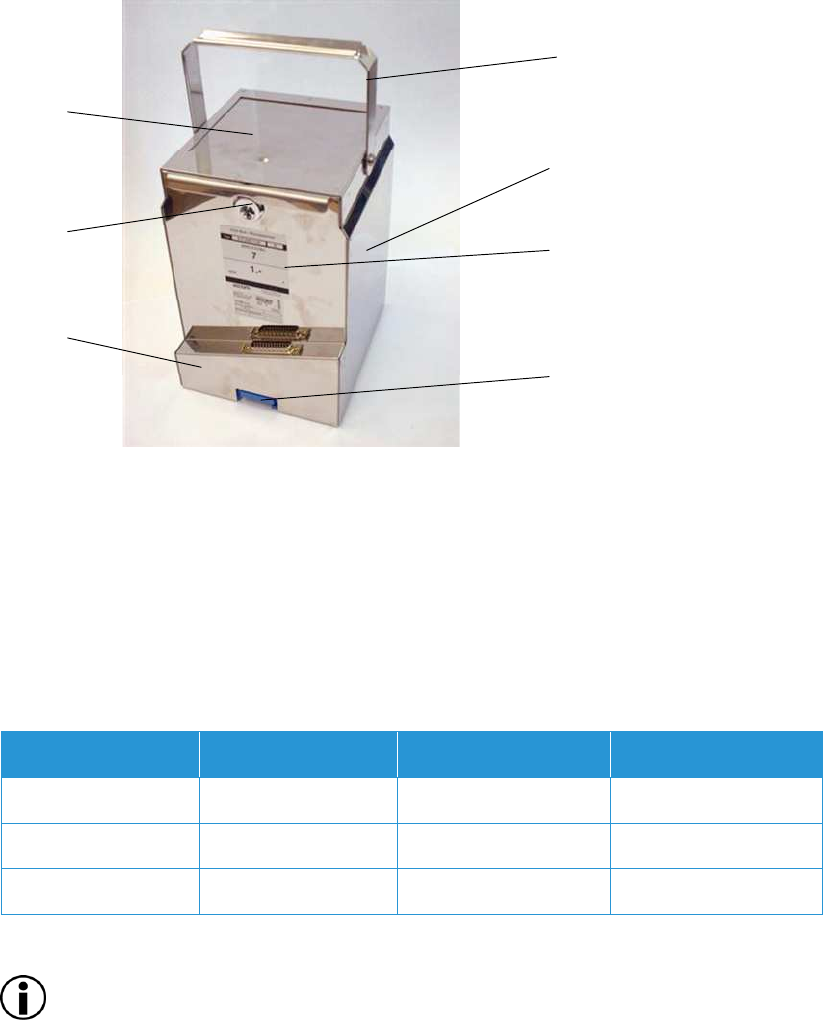
2.7.7 Bulk Coin Storage Unit
The Bulk Coin Storage Unit (BUCO) is designed to store coins with a maximum diameter of
29.5 mm and a maximum thickness of 2.50 mm. It is basically a capacity extension of the
coin drums. Thanks to its large capacity, the BUCO assures a prolonged availability of the
most frequently used coins for change return. The BUCO contains a handle that allows for
easy removal and transport by revenue officers. The process for changing BUCOs will be
explained in the Maintenance and Training manuals at Final Design Review (FDR).
Handle
Coin
container
Label with
ELCO
number
Connection to
the control unit
Lid
Lock
Pedestal
Figure 2-17: Principle Underlying the Function of the BUCO
Physically, the FVD can hold up to three BUCOs, each for a different type of coin, whereby
one BUCO is placed inside the RS-chassis and the others outside on a pedestal. The coins
being returned to the passenger fall through an opening in the base of the BUCO into the
output tray. An optical sensor in the base of the BUCO records the number of coins returned.
Each BUCO has its unique ELCO number. This allows a clear identification of every BUCO.
A signal indicates the status of the BUCO. It becomes active once the BUCO is empty. The
BUCO is not self-refilling and must always be filled with the correct type and number of
coins. See Table 2-13: BUCO — Initial Configuration and Capacity.
Parameter Denomination Initial Quantity BUCO Capacity
First BUCO $0.05 One per FVD 2,000
Second BUCO $0.25 One per FVD 1,500
Third BUCO $1.00 One per FVD 1,000
Table 2-13: BUCO — Initial Configuration and Capacity
NOTE
Note: Only one type of coin can be put in the BUCO. If physical parameters vary between
different series of the same coin, such as old and new, only one type can be filled in.
FVD Expert 9100 US Dok-Nr: 10-000-006-785 - SP - 00 - EN / Version: 04 33 / 57
©Xerox / These materials are considered confidential and proprietary!
2.8 Banknote Recycler
The following subsections contain additional information on the banknote recycler (BNR).
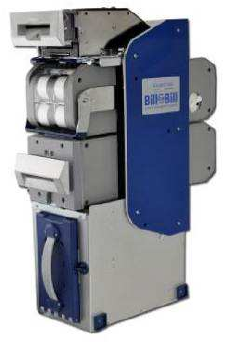
2.8.1 Banknote Recycler CashCode
The Bill-to-Bill™ 300XE bill recycler was developed to validate bills that have a width of up to
82 mm. Compared to the previous front-load bill recycler models, the Bill-to-Bill™ 300XE has
the following distinctive features:
• It utilizes a lightweight plastic shockproof cash box.
• It has three recycling cassettes with a capacity of 100 bills each, with an option for se-
cured lockable.
• It has the capacity to dispense up to one pack of 20 bills.
The Bill-to-Bill™ 300XE bill validator consists of five main modules:
• The Bill-to-Bill 300XE™ recycler is designed to accommodate bills of different sizes from
62- to 82-mm wide, and from 125- to 172-mm long, which represents most of the world
currencies.
• Certain currencies have different widths depending on denomination. For accurate vali-
dation of such currencies, the Bill-to-Bill™ 300XE validating head has a centering mech-
anism that aligns the bills for processing different widths.
• The lockable-removable cash box is used for temporary storage of validated bills. It can
be locked with two standard ¾-inch tubular locks.
• Bill capacity refers to the number of new bills that the cash box can store. Actual cash
box capacity can decrease in real applications due to variations in thickness of street-
grade bills.
• The Bill-to-Bill™ 300XE housing joins all the other modules. It is meant to be permanent-
ly secured inside a host machine.
• Software updates can be easily applied to Bill-to-Bill™ 300XE using a memory card or
through a network.
• The bill-to-bill system uses radio frequency identification electronic tracking in cash box-
es.
Figure 2-18: CashCode BNR

34 / 57 Dok-Nr: 10-000-006-785 - SP - 00 - EN / Version: 04 FVD Expert 9100 US
© Xerox / These materials are considered confidential and proprietary!
2.8.1.1 CashCode Parameters
Parameter Description
Bill Validation Rate 98% or higher
Bill Insertion Lengthwise 4 ways
Escrow Multi-bill programmable
Interfaces Supported Bi-directional (RS232), USB
Protocols CCNET
Firmware Updates BlueChipTM Smart-Stick memory or downloadable
Operating Voltage 24 V DC
Power Requirements 4A max.
Bulk Loader Speed 1.2 seconds per bill — up to 25 bills
Dimensions (W x H x D) 163 X 569 X 378 mm
Recycling Cassette 3 x 100 – 120 bill capacity intelligent cassettes
Drop Cassette Sizes A Valuable 1,000 bills
Approval UL listed
Denomination USD
Max. Number of Different Banknotes 13
Prepared Acceptance of Banknote Denomina-
tions USD notes
Max. Quantity of Notes per Product Purchase 15
Number of Different Notes in Recycling Unit 3
Capacity of Different Notes in Recycling Unit 70/30
Maintenance All components can be maintained completely from
front side. Device can stay in mounted position.
BNR Definition of Change Notes To be decided with SEPTA by FDR.
BNR Definition of Cash Box Denomination To be decided with SEPTA by FDR.
Table 2-14: CashCode Datasheet Extraction

FVD Expert 9100 US Dok-Nr: 10-000-006-785 - SP - 00 - EN / Version: 04 35 / 57
©Xerox / These materials are considered confidential and proprietary!
2.9 Electronic Transfer of Funds-Point of
Sale
The following subsections contain information regarding the personal identification number
(PIN) pad.
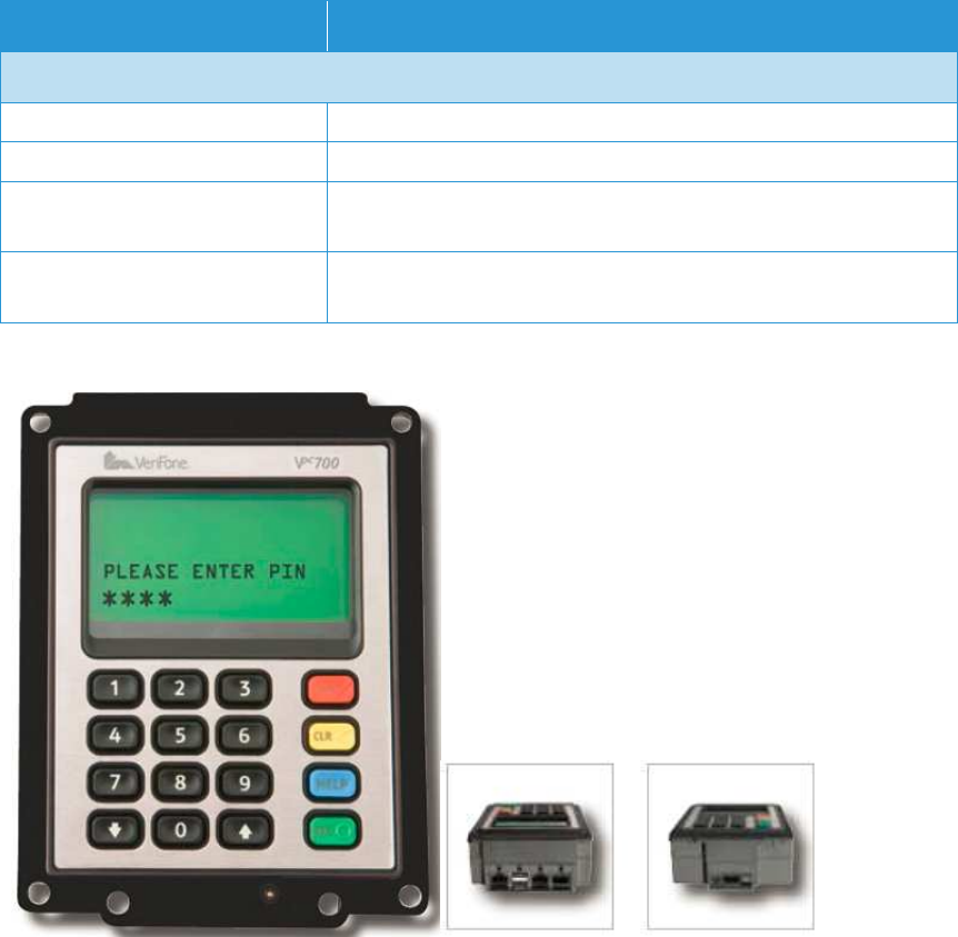
2.9.1 PIN Pad and LCD Display
The EFT solution — hardware, software, licenses and maintenance contract — is the Veri-
Fone Vx700, a vandal-resistant, low-power, outdoor-rated module. The form factor of the
VeriFone Vx700 is a 16-key PIN Pad with a 128 x 64 graphical display, which will be coupled
with the VeriFone SCR710 smart card reader with multiple contactless interface modules to
form a highly flexible payment solution.
It complies with the latest Payment Card Industry (PCI), PIN Entry Device (PED) and
Europay, MasterCard and Visa (EMV) standards to protect cardholder information. It also
has an IP65 rating and an impact resistance of 10J. It operates at a wide range of input volt-
ages and incorporates low power and power saving modes to reduce consumption.
Feature Description
Processor 200 MHz ARM9 32-bit microprocessor
Memory 6 MB: 4 MB flash, 2 MB SRAM — optional 12 MB
Display
Type LCD with backlight
Visible Area 128 x 64 pixel, 4 lines x 21 characters at standard font
Keypad
Keypad 16-key keypad (3 x 4 numeric, plus four function keys); external
interface for another four function, user-defined keys
Security
Online/Offline PCI PED 1.3 online and approved AES256 encryption offline
Key Management Master/session and DUKPT
Authentication VeriShield file authentication
Power
Power Supply 9V DC to 28V DC
Consumption 1.5W full speed
1W low-power mode
0.39W sleep mode
Connectivity
Connectivity 4 x RS232 serial ports
2 x USB 2.0 host ports
1 x USB 2.0 slave ports
Height (Overall) 132 mm
Width 100 mm
Depth 49 mm
36 / 57 Dok-Nr: 10-000-006-785 - SP - 00 - EN / Version: 04 FVD Expert 9100 US
© Xerox / These materials are considered confidential and proprietary!
Feature Description
Environmental Characteristics
Front Panel Stainless steel
Temperature Range -25°C to 60°C (-13°F to 140°F) operating temperature
Humidity 5% to 95% relative humidity (non-condensing)
IP65 sealed
Durability IK09 vandal resistant — 10 joules impact
Petroleum and chemical resistant
Table 2-15: VeriFone Vx700 Datasheet Extraction
Figure 2-19: PIN Pad
FVD Expert 9100 US Dok-Nr: 10-000-006-785 - SP - 00 - EN / Version: 04 37 / 57
©Xerox / These materials are considered confidential and proprietary!
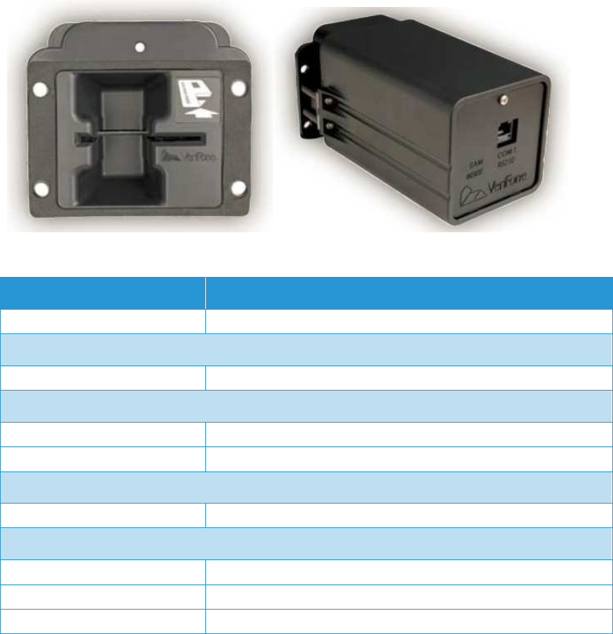
2.9.2 Card Reader
The VeriFone SCR710 — hardware, software, licenses and maintenance contract — pro-
vides track 1, 2, and 3 magnetic stripe-reading with a EMV 4.0 chip interface. The VeriFone
SCR710 provides advanced security features such as Triple Data Encryption Standard
(DES) (3DES) and is PCI PED 1.3-approved.
The reader is easily integrated into the FVD with a small form factor and shuts out foreign
object insertions with an integrated shutter. The unit also meets exterior standards such as
IP54, and is rated for extreme temperature ranges for outdoor usage.
Figure 2-20: VeriFone Card Reader
Feature Description
Processor ARM9
Security
Online/Offline PCI PED 1.3 online and approved 3DES encryption offline
Power
Power Supply 12V DC to 25V DC
Consumption 2.4W max
Connectivity
Connectivity 1 x serial port
Environmental Characteristics
Temperature Range -20°C to 60°C (-4°F to 140°F) operating temperature
Humidity 5% to 95% relative humidity (non-condensing)
Durability IP54 front panel, IP34 internal rear enclosure
Table 2-16: VeriFone SCR710 Datasheet Extraction
38 / 57 Dok-Nr: 10-000-006-785 - SP - 00 - EN / Version: 04 FVD Expert 9100 US
© Xerox / These materials are considered confidential and proprietary!
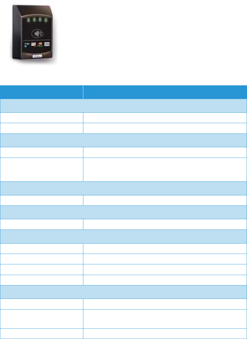
2.9.3 Card Open Payment Contactless Reader
The ViVOpay Kiosk is a bolt-on external reader module that can be easily be added to exist-
ing FVD systems to add new contactless payment functionality. The ViVOpay Kiosk’s com-
pact design and rugged weatherproof construction allows it to be used in self-ordering kiosk
systems in public transit.
The ViVOpay Kiosk is certified with most contactless payment programs such as Mainte-
nance Support Device (MSD)-based MasterCard® PayPass®, ExpressPay® from American
Express®, Visa® payWave and Discover® Zip™ and capable of EMV-based OneSmart®,
MasterCard® PayPass® and Visa® payWave quick Visa® Smart Debit/Credit (qVSDC).
Figure 2-21: ViVOpay Kiosk
Feature Description
Hardware
Processor ARM processor
Audio/Visual Beeper and LEDs
Contactless Transactions
Interface 13.56 MHz ISO 14443 Type A/Type B and MiFare
Payment Applications American Express® ExpressPay®, Discover® Zip™, Master-
Card® PayPass® Mstripe (M/Chip capable), Visa® payWave MSD
and (qVSDC capable), JCB/Jspeedy
Power
Input Power 7.5-45V DC, 700mA
Connectivity
Connectivity 1 x RS232 serial port
Physical Characteristics
Height (overall) 107.4 mm
Width 31.5 mm
Length 78.0 mm
Weight 27.2 g (0.60 pounds)
Environmental Characteristics
Front Panel Weather-proofed UV-rated plastic enclosure
Temperature Range -25°C to 70°C (-13°F to 158°F) operating temperature
-40°C to 85°C (-40°F to 185°F) storage temperature
Humidity 10% to 90% relative humidity (non-condensing)
Table 2-17: ViVOpay Kiosk Datasheet Extraction
FVD Expert 9100 US Dok-Nr: 10-000-006-785 - SP - 00 - EN / Version: 04 39 / 57
©Xerox / These materials are considered confidential and proprietary!
2.10 Card Dispenser Unit
The following subsections contain information regarding the card dispenser unit.
2.10.1 Overview
The card dispenser unit is used to check and issue GPRs.
A card dispenser unit consists of:
• Card transport unit (CTU)
• Card dispenser with magazine
• GPR antenna for card dispenser unit
The CTU and the card reader/writer module are built into the FVD. The card magazine can
easily be removed to refill cards. Each card magazine is filled with GPRs. Once filled, the
card magazine is reconnected to the corresponding card dispenser module.
• In the case of a corrupt card, it will follow the usual path in the return channel. A flap will
be activated to guide the card to drop onto a podium inside the FVD.
• The FVD comes with two card dispenser units for GPRs.
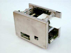
2.10.2 Card Transport Unit
The CTU implements the entire functionality required to mechanically move, hold and
transport CSCs and CSTs. The rollers moving the card are made of specially treated polyu-
rethane, which allows the CTU to be used under harsh environmental conditions.
Figure 2-22: Card Dispenser Unit
40 / 57 Dok-Nr: 10-000-006-785 - SP - 00 - EN / Version: 04 FVD Expert 9100 US
© Xerox / These materials are considered confidential and proprietary!
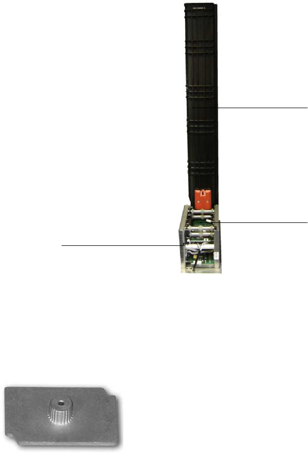
2.10.3 Card Dispenser with Card Magazine
The card magazine holds a maximum of 650 GPRs with a card thickness of 0.76 mm. An in-
dividual ELCO number, or serial number, issued by the manufacturer uniquely identifies
each card magazine.
CTU
Card Dispenser
Podium
Card Magazine
Figure 2-23: Card Dispenser with Card Magazine
2.10.4 Weight
The purpose of the weight in the card magazine is to put sufficient pressure on the cards
throughout the entire dispensing process. There is also adequate pressure on the last cards
to guarantee they are correctly dispensed.
Figure 2-24: Card Magazine Weight
FVD Expert 9100 US Dok-Nr: 10-000-006-785 - SP - 00 - EN / Version: 04 41 / 57
©Xerox / These materials are considered confidential and proprietary!
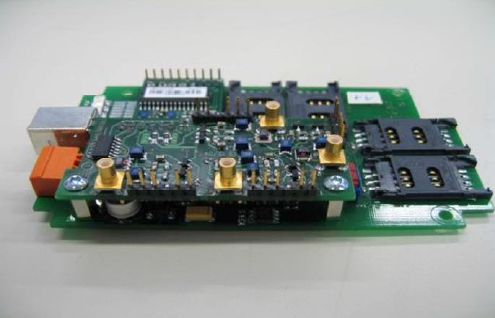
2.11 Card Access Module
The card access module (CAM) includes two antennas that are used to check the product of
the GPRs. The antennas are installed into the two CTUs.
The mentioned CAM reader/writer is used to encode the cards (fare media on
ISO/IEC 14443-2-compliant technology):
• Supports ISO 14443 Type A and B and ISO 14443 tags
• Support of maximum of four secure access modules (SAMs)
• Has an optional antenna switch to share the module with four antennas
• Has a Universal Serial Bus (USB) interface
• Has speed-optimized firmware
• Supports:
− DESfire EV1 4K Version 2
− MIFARE Ultralight C
− MIFARE SAM AV2
Figure 2-25: CAM Reader/Writer and Antenna Switch Module
42 / 57 Dok-Nr: 10-000-006-785 - SP - 00 - EN / Version: 04 FVD Expert 9100 US
© Xerox / These materials are considered confidential and proprietary!
2.12 Printer System
The following subsections contain information regarding the printer system.
2.12.1 Overview
The FVD is equipped with one printer AP5200MC for MMSR and an AP4200 for paper re-
ceipts.
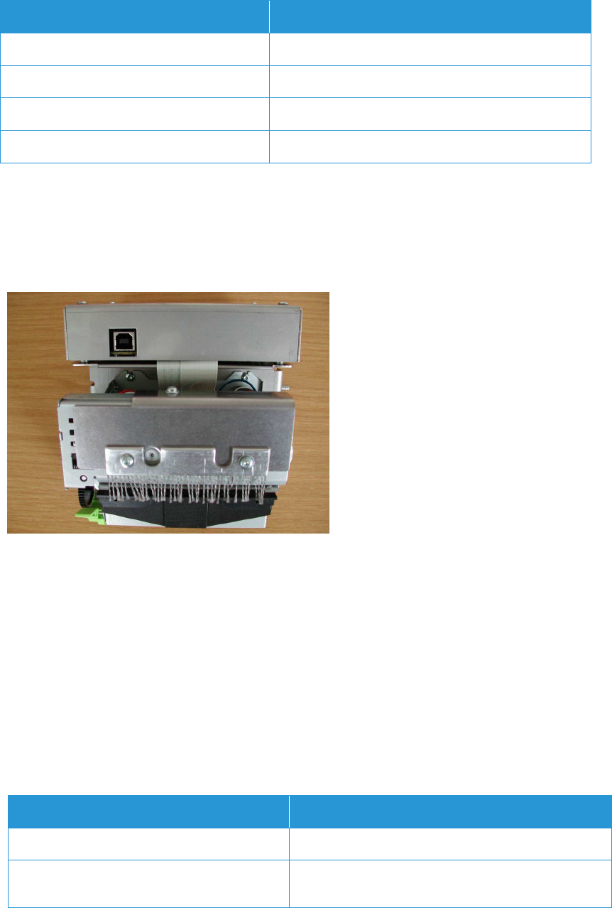
2.12.2 Magnetic Media Swipe Reader AP5200MC Printer
Figure 2-26: Receipt Printer — AP 5200MC
The printing module contains
• A burster to separate fan-folded MMSRs
• A magnetic encoding unit
• A printing unit
Its compact size and reliable hardware makes it the ideal module for the FVD environment.
Attributes of the AP5200MC:
• Supports two stocks of paper (fan folded)
• Rejection bin to sort defective media.
• Each stock with a capacity of maximum 1600
• Thermal printer module mounted on a removable guidance support
• Second path to switch over if one paper stock finish
FVD Expert 9100 US Dok-Nr: 10-000-006-785 - SP - 00 - EN / Version: 04 43 / 57
©Xerox / These materials are considered confidential and proprietary!
The paper feed path selects the paper media and feeds the selected paper to the reader.
Feature Description
Print Method Direct thermal
Resolution 203 x 203 dpi (8 dots/mm)
Magnetic Characteristics Supported track: ISO Track 3 (according ISO 7811)
Bit Density Between 75 and 210 bpi (in 14 steps)
Table 2-18: AP5200MC — Datasheet Extraction
2.12.3 Receipt Printer AP4200
The thermal printer module is mounted on a removable guidance support. One paper stock
with a maximum capacity of 1,000 receipts is installed.
Figure 2-27: Receipt Printer — AP 4200
The printer uses the thermal printing technique. All types of media that are processed by this
printer must have the same width. The paper must comply with the Xerox specification — it
must be certified by Xerox and delivered by a Xerox-approved manufacturer.
Attributes of the AP4200:
• Thermal printer module mounted on a removable guidance support
• One stock with a capacity of maximum 1000 receipts.
2.12.4 Paper
The detailed paper specification will be part of a specific document.
Parameter Description
Width 82.5 mm or approximately 3.25 inches
Length Variable receipt length, from 50 mm to 100 mm or
approximately 1.97 inches to 3.94 inches
Table 2-19: AP 4200 Paper
44 / 57 Dok-Nr: 10-000-006-785 - SP - 00 - EN / Version: 04 FVD Expert 9100 US
© Xerox / These materials are considered confidential and proprietary!
2.13 Control Electronics
The following subsections contain information regarding the technical data of the FVD.
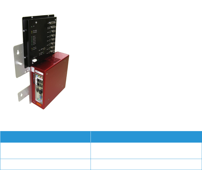
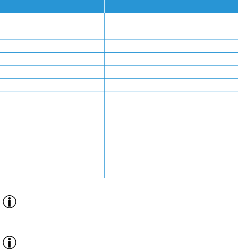
2.13.1 Overview
The FVD is controlled by a personal computer (PC) platform with the necessary interfaces.
The single board computer (SBC) is the most important component of the main control unit
(MCU) 4.0. Those interfaces that are not provided on the SBC — serial 1 – serial 6, USB 0,
input/output (I/O) and 24V out/door control — are integrated on the connector module
(COMO), which is connected to the SBC internally via the USB.
Figure 2-28: MCU 4.0
Feature Description
SBC and Hard Disk SBC and host of FVD software application and opera-
tional data — in the red box
COMO Interface module — in the black box
Table 2-20: SBC and COMO Information
A 2.5-inch hard disk serves as the permanent data carrier for the operating system and pro-
grams and cannot be replaced without opening the MCU 4.0.
FVD Expert 9100 US Dok-Nr: 10-000-006-785 - SP - 00 - EN / Version: 04 45 / 57
©Xerox / These materials are considered confidential and proprietary!
2.13.2 Main Control Unit 4.0 Technical Data
See Table 2-21: MCU 4.0 — Datasheet Extraction.
Feature Description
CPU 1.6 GHz, 32 bit
Hard Disk Automotive 2.5-inch hard disk; >= 80 GB
Memory 4 GB max.
Ethernet 2x 10/100/1000 Base-T Ethernet
Display Standard VGA
USB 1 5x USB 2.0 — four on the front, one USB on the COMO
Serial Port 2 COM1 on the front — Serial 1
COM3 – COM8 on the COMO
I/O Port 4 x TTL Output — open collector
8 x TTL Input — current loop
4 x switchable 24 V DC — 500mA
Audio Line-in/line-out on the front for application wave mes-
sages
Power supply 24 DC, 35W max, 24 V for COMO
Table 2-21: MCU 4.0 — Datasheet Extraction
NOTE
All USB 2.0 interfaces support bootable USB storage devices depending on the Basic Input
Output System settings.
NOTE
When numbering COM interfaces assigned by the operating system, onboard interfaces are
counted first. As a result, “serial 1” corresponds to “COM3” on the COMO, “serial 2” corre-
sponds to “COM4”, etc.
2.13.3 Backup Functionality
A compact flash card as a mobile data carrier and or backup medium with minimal 512 MB is
required. If not inserted, the backup functionality is not available.
2.13.4 Operating System/Software
The operating system is Windows embedded Standard 2009 (Windows XP embedded).
46 / 57 Dok-Nr: 10-000-006-785 - SP - 00 - EN / Version: 04 FVD Expert 9100 US
© Xerox / These materials are considered confidential and proprietary!
2.14 Power Interfaces
The mains power standards shown in Table 2-22: MCU 4.0 — Datasheet Extraction are required.
Table 2-22: MCU 4.0 — Datasheet Extraction
The AC main supply line to the FVD has to be fused with a 20 A fuse. Mains cable cross section de-
pends on cable length. The maximum cross section of the terminal clamp is 4 mm2.
2.15 Power Supply
The power manager must be able to guarantee the finalization of an open product vending
transaction and a secure PC shutdown in case of a mains failure.
An uninterruptible power supply is in the power manager integrated. The uninterruptable
power supply (UPS) backup is an electrical apparatus that provides emergency power to a
load when the input power source, typically mains power, fails.
Figure 2-29: Power Manager
UPS key characteristics are as shown in Table 2-23: Data of the Integrated UPS — Sheet
Extraction.
Feature Description
Power 480W
Voltage 24V DC UPS
Table 2-23: Data of the Integrated UPS — Sheet Extraction
Feature Description
AC Input 115V +/-15%
Frequency 60 Hz +/-3 Hz
Current Standard
Standby < 1.2 A
Operation < 2.8 A without heating
Worst Case < 10 A
FVD Expert 9100 US Dok-Nr: 10-000-006-785 - SP - 00 - EN / Version: 04 47 / 57
©Xerox / These materials are considered confidential and proprietary!
2.16 X-Bus Device
The X-bus device acts as a slave I/O module connected to a proprietary bus system, mas-
tered by the power manager. The power manager and their slave modules build an auto-
nomic I/O control system.
This configuration has the advantage of being able to control the security features without a
host.
Door switch, lock switch and dry contact are connected to the X-bus device. An intrusion at-
tempt will be detected. In case of an intrusion, the dry contact can control a siren or a flash-
ing light.
An intrusion attempt can be detected in power state “on” or “off.”
2.17 Main Failure
As soon as the input voltage falls below the lower limit — mains failure — the UPS switches
to battery and the power-fail signal is sent to the MCU 4.0. If the input voltage rises over the
lower limit (mains power is back) before a timeout of approximately 2 seconds, the UPS
switches back to the mains.
48 / 57 Dok-Nr: 10-000-006-785 - SP - 00 - EN / Version: 04 FVD Expert 9100 US
© Xerox / These materials are considered confidential and proprietary!
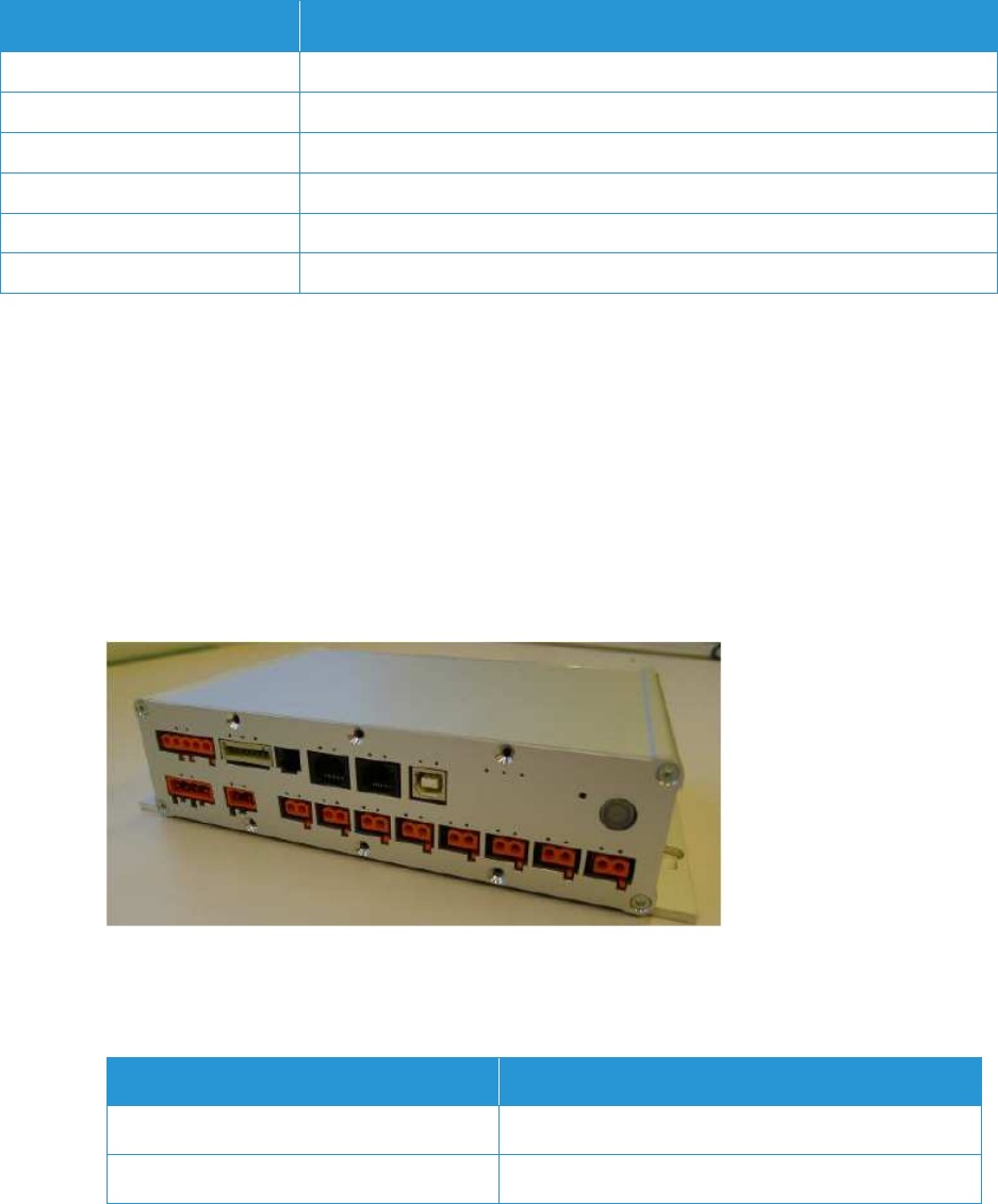
2.18 AC/DC Converter — Main Control Unit
Supply
Figure 2-30: AC/DC Converter is an image of the AC/DC converter and Table 2-24: AC/DC
Converter — Datasheet Extraction for MCU Supply contains specification information for the
AC/DC converter.
Figure 2-30: AC/DC Converter
Feature Description
AC Input 90V to 264V
Frequency 45 Hz to 65 Hz
Rating 480W
Power Factor 0.95
Table 2-24: AC/DC Converter — Datasheet Extraction for MCU Supply

FVD Expert 9100 US Dok-Nr: 10-000-006-785 - SP - 00 - EN / Version: 04 49 / 57
©Xerox / These materials are considered confidential and proprietary!
2.19 Battery
Two serial valve-regulated lead-acid (VRLA) batteries are connected to the UPS. They pro-
vide secure internal feeding if the power supply voltage is disconnected.
The expected durability of the battery is between three and four years. However, batteries
are consumable and are therefore excluded from the warranty. If the batteries are put in
storage, they have to be recharged every six months for at least six hours in order to prevent
potential damage.
Figure 2-31: Battery Module
Feature Description
Technology VRLA
Voltage 2 x 12V DC
Capacity 2.3 Ah
Table 2-25: Battery – Datasheet Extraction
The capacity of the battery is sufficient to cover the FVD under complete load (including
printing of tickets). This is under the following preconditions:
• The battery has been loaded completely before the first mains power failure
• The battery is in a good status
50 / 57 Dok-Nr: 10-000-006-785 - SP - 00 - EN / Version: 04 FVD Expert 9100 US
© Xerox / These materials are considered confidential and proprietary!
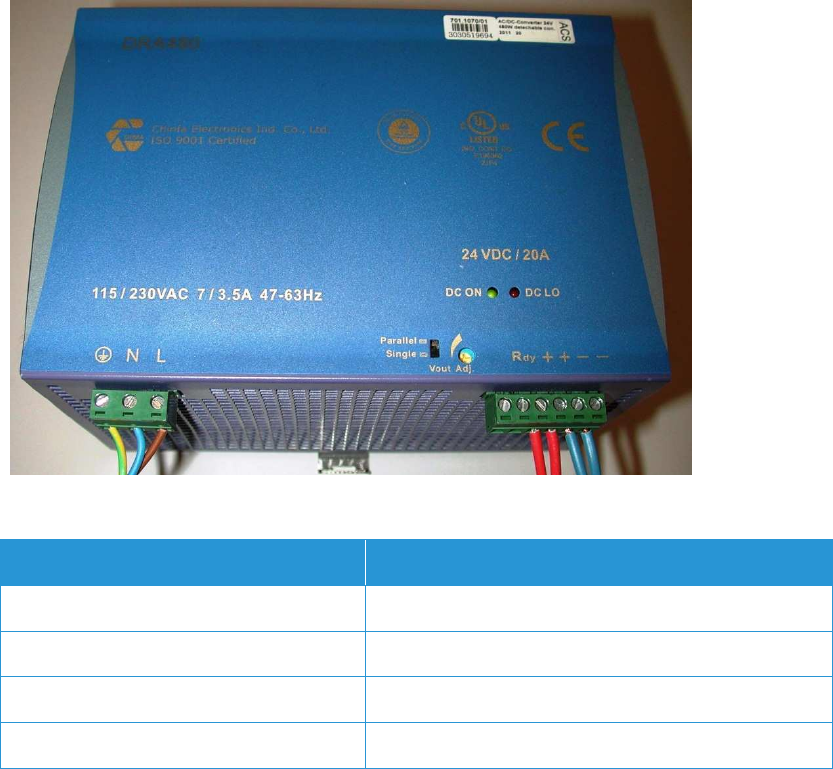
2.20 Service Plug
For service personnel, the FVD is equipped with one power outlet (115V, fused with 10A) in-
side the housing.
Figure 2-32: Service Plug
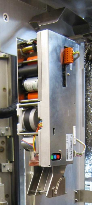
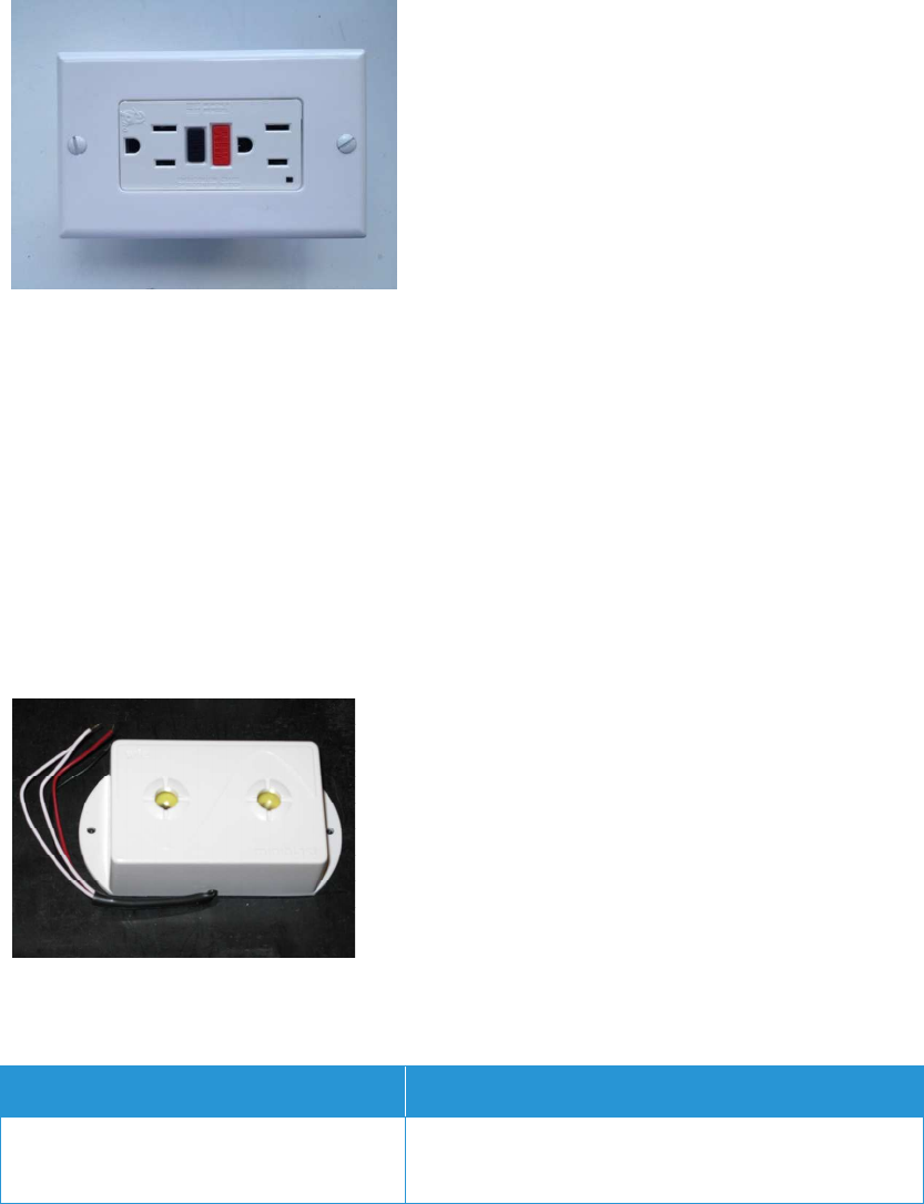
2.21 Siren
A siren is switched on for a preset period of time in case of:
• An unauthorized opening of the FVD door — break-in alarm, which is activated by the
door/lock surveillance
• Opening of the door, but the service code is not entered within a given time or a wrong
code is entered for three times
The siren is located behind the coin handling system in the FVD housing. This is intended to
avoid a fast turning-off of the siren by a break-in.
Figure 2-33: Siren
The siren is powered for at least one hour while operating on battery back-up.
Feature Description
Volume 100 dB at a distance of 1 meter (door open)
75 dB at a distance of 1 meter (door closed)
Table 2-26: Siren — Sheet Extraction
FVD Expert 9100 US Dok-Nr: 10-000-006-785 - SP - 00 - EN / Version: 04 51 / 57
©Xerox / These materials are considered confidential and proprietary!
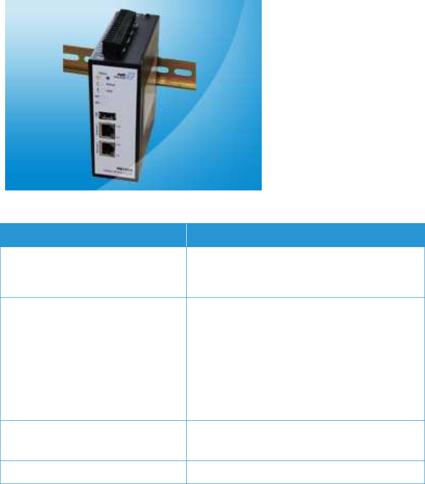
2.22 Communication Interfaces
For the communication between the FVDs and Central Data Collection and Reporting Sys-
tem (CDCRS), there will be two different communication modules. On the “Full Function”
FVD the NB1600-Wireline will be integrated, and in the “Cashless” FVD the NB1600-LTE will
be integrated.
2.22.1 NB1600-Wireline Functions
The NB1600-Wireline is a local area network (LAN)-LAN communication module and acts as
device server, industrial firewall, Virtual Private Network (VPN) router, protocol converter, I/O
module or simple IPC.
The NB1600-Wireline industrial firewall function separates the local network from the factory
LAN and allows a system to connect to a central server using only one VPN connection. Us-
ing TCP port 80 for the VPN allows the passing of most firewalls in a factory or on the cus-
tomer side.
Figure 2-34: NB1600-Wireline
Feature Description
Ethernet 2 Ethernet ports, 10/100 Mbps, Auto MDX, bridged or
routed
Connector type: RJ45
Digital I/O 2 digital inputs, maximum input voltage of 40V DC,
minimum voltage for level 1 (set) is 7.2V DC, maximum
voltage for level 0 (not set) is 5.6V DC.
Note: A negative input voltage is not recognized.
2 digital outputs, limiting continuous current: 1 A, maxi-
mum switching voltage of 60V DC, 42 VAC (Vrms)
Maximum switching capacity of 60 W
Connector type: 8 pins of 15-pin terminal block
Serial Interface Protocol: 3-wire RS232
Connector type: 3 pins of 15-pin terminal block
Service Interface USB host interface providing support for memory de-

52 / 57 Dok-Nr: 10-000-006-785 - SP - 00 - EN / Version: 04 FVD Expert 9100 US
© Xerox / These materials are considered confidential and proprietary!
Feature Description
vices
Connector type: USB type A
Power Redundant power supply inputs
Input voltage: 12V DC to 48V DC (-15%/+20%)
Maximum power consumption: 5W
Connector type: 2+2 pins of 15-pin terminal block
Dimensions 124.2 mm x 45 mm x 98.9 mm, ca. 450 g
Table 2-27: NB1600-Wireline — Sheet Extraction
2.22.2 NB1600-LTE Wireless Router — Optional
The NB1600-LTE is the industrial mobile broadband router in the FVD.
For mobile internet access a 2G/3G+/4G modem is embedded. All services from Global
Packet Radio Service (GPRS) to Long Term Evolution (LTE) are supported — the best
available service is selected automatically.
The NB1600-LTE offers two Ethernet ports that are highly configurable. Used as LAN ports,
they may form a 2-port switch or have two separated and routed IP networks. Used as wide
area network (WAN) ports, the NB1600-LTE acts as an industrial firewall with optional 3G
backup and VPN client functionally.
Figure 2-35: NB1600-LTE Wireless Router
Feature Description
Mobile interface Multimode LTE/4G, HSPA+/3.5G, UMTS/3G,
EDGE/2.5G, GPRS and GSM/2G
Global connectivity with LTE 800/900/1800/2100/2600
MHz and UMTS/HSPA+ 900/2100 MHz,
GSM/GPRS/EDGE 850/900/1800/1900 MHz
Data rates: max. 100 Mbps downlink/50 Mbps uplink
Antenna connector: SMA female
Digital I/O 2 digital inputs, maximum input voltage 40V DC, mini-
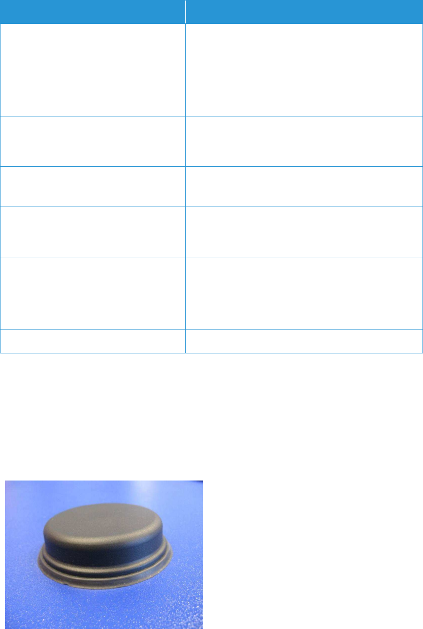
FVD Expert 9100 US Dok-Nr: 10-000-006-785 - SP - 00 - EN / Version: 04 53 / 57
©Xerox / These materials are considered confidential and proprietary!
Feature Description
mum voltage for level 1 (set): 7.2V DC, maximum volt-
age for level 0 (not set): 5.6V DC. Note: a negative
input voltage is not recognized.
2 digital outputs, limiting continuous current: 1 A, maxi-
mum switching voltage 60V DC, 42 VAC (Vrms), maxi-
mum switching capacity: 60W
Connector type: 8 pins of 15-pin terminal block
Ethernet 2 Ethernet ports, 10/100 Mbps, Auto MDX, bridged or
routed
Connector type: RJ45
Serial Interface Protocol: 3-wire RS232
Connector type: 3 pins of 15-pin terminal block
Service Interface USB host interface providing support for memory de-
vices
Connector type: USB type A
Power Redundant power supply inputs
Input voltage: 12V DC to 48V DC (-15%/+20%)
Maximum power consumption: 5W
Connector type: 2+2 pins of 15-pin terminal block
Dimensions and Weight 124.2 mm x 45 mm x 98.9 mm, ca. 450 g
Table 2-28: NB1600-LTE Wireless Router — Sheet Extraction
2.22.3 Antenna
For the connection to Universal Mobile Telecommunications System (UMTS)/High Speed
Packet Access (HSPA) and GPRS/Enhanced Data rates for GSM Evolution (EDGE), a com-
bined antenna is used, which will be mounted on the roof of the FVD in a vandal-proof mod-
el. The antenna is inconspicuously mounted on the roof of the FVD, and is therefore not ob-
viously visible.
Figure 2-36: Antenna
54 / 57 Dok-Nr: 10-000-006-785 - SP - 00 - EN / Version: 04 FVD Expert 9100 US
© Xerox / These materials are considered confidential and proprietary!
2.23 Loudspeaker and Connector for Head-
phone Audio Amplifier
For an acoustics passenger user interface a loudspeaker and a headphone connector (3.5
mm mono jack) are provided. The loudspeaker is operated by a 10W amplifier.

FVD Expert 9100 US Dok-Nr: 10-000-006-785 - SP - 00 - EN / Version: 04 55 / 57
©Xerox / These materials are considered confidential and proprietary!
2.24 Service Panel
If the door is open, the maintenance application will be displayed on the internal service
panel. When the door is closed, only the external touch screen is in use. By opening the
door, “FVD out of order” appears on the external touch screen and no manipulation is possi-
ble on the external touch screen.
The behavior and the functionality of the internal service screen will be the same as that of
the external touch screen. The log-in functionality has to be completed on the external touch
screen. An in-depth description is explained in the Fare Vending Device Functional Specifi-
cation document. Table 2-29: Service Panel — Sheet Extraction contains the specifications.
Figure 2-37: Service Panel
Feature Description
Diagonal Size 7 inches
Active Area 152.4 x 91.44 mm
Bezel Opening Area 154.6 x 93.64 mm
Pixel Number 800 x RGB x 480 pixels
Pixel Pitch 0.1905 x 0.1905
Pixel Arrangement RGB vertical stripe
Bezel Opening Area a-si TFT active matrix
Display Colors 262k or 16.2M colors
Display Mode Normal white
Surface Treatment Antiglare, hard coating ( 3H )
Table 2-29: Service Panel — Sheet Extraction
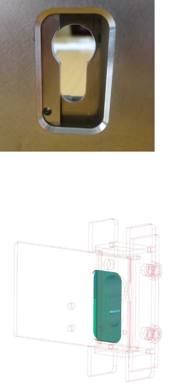
56 / 57 Dok-Nr: 10-000-006-785 - SP - 00 - EN / Version: 04 FVD Expert 9100 US
© Xerox / These materials are considered confidential and proprietary!
1.1 Dust Cover
The locking mechanism is flush mounted on the door plate and protects the drill resistant
lock against dust.
Figure 2-38: Dust Coverl
Any dust or water that might stick on the cover falls along the housing inside and is dropped
and drained out of the chassis at the bottom.
Figure 2-39: Dust Cover (technical View)
To open the cover the staff inserts a blocking pin or screwdriver into the small hole and
moves the cover to the right exposing the lock. The cover can be secured in the open posi-
tion by inserting the blocking pin deeper when the cover is in the open position. The cover is
automatically closed by removing the blocking pin.

FVD Expert 9100 US Dok-Nr: 10-000-006-785 - SP - 00 - EN / Version: 04 57 / 57
©Xerox / These materials are considered confidential and proprietary!
3 Norms and Standards
Table 3-1: Norms and Standards contains the norms and standards for CE/ETL, safety, elec-
tromagnetic compatibility and radio approval.
Criteria Description
CE/ETL Conformity declaration
Safety Compliant with IEC 60950 with certification for the
national characteristics for the United States
Electromagnetic Compatibility Compliant with EN50121-4:2006/IEC 61000-6-
2/IEC 61000-6-3
Radio Approval Title 47 of the Code of Federal Regulations Part
15, Subpart
Table 3-1: Norms and Standards
3.1 Operational Conditions
The FVD operates under the temperature and humidity conditions shown in Table 3-2: Envi-
ronment and Climate.
Criteria Description
Maximum Temperature +45°C (outdoor)
Minimum Temperature with Heating -30°C (outdoor)
Relative Humidity 10 % to 90 % rH, non-condensing
Solar irradiation No direct sunlight — the FVDs must be sheltered
accordingly
Table 3-2: Environment and Climate