ACSS an L 3 Communications and Thales T3K-4M TCAS II User Manual a
ACSS an L-3 Communications and Thales Company TCAS II a
UserManual.wiki
>
ACSS an L 3 Communications and Thales
>
T3K 4M User Manual
User Manual
Navigation menu
Upload a User Manual
Namespaces
Wiki Guide
HTML
PDF
Info
Views
User Manual
Discussion / Help
Navigation


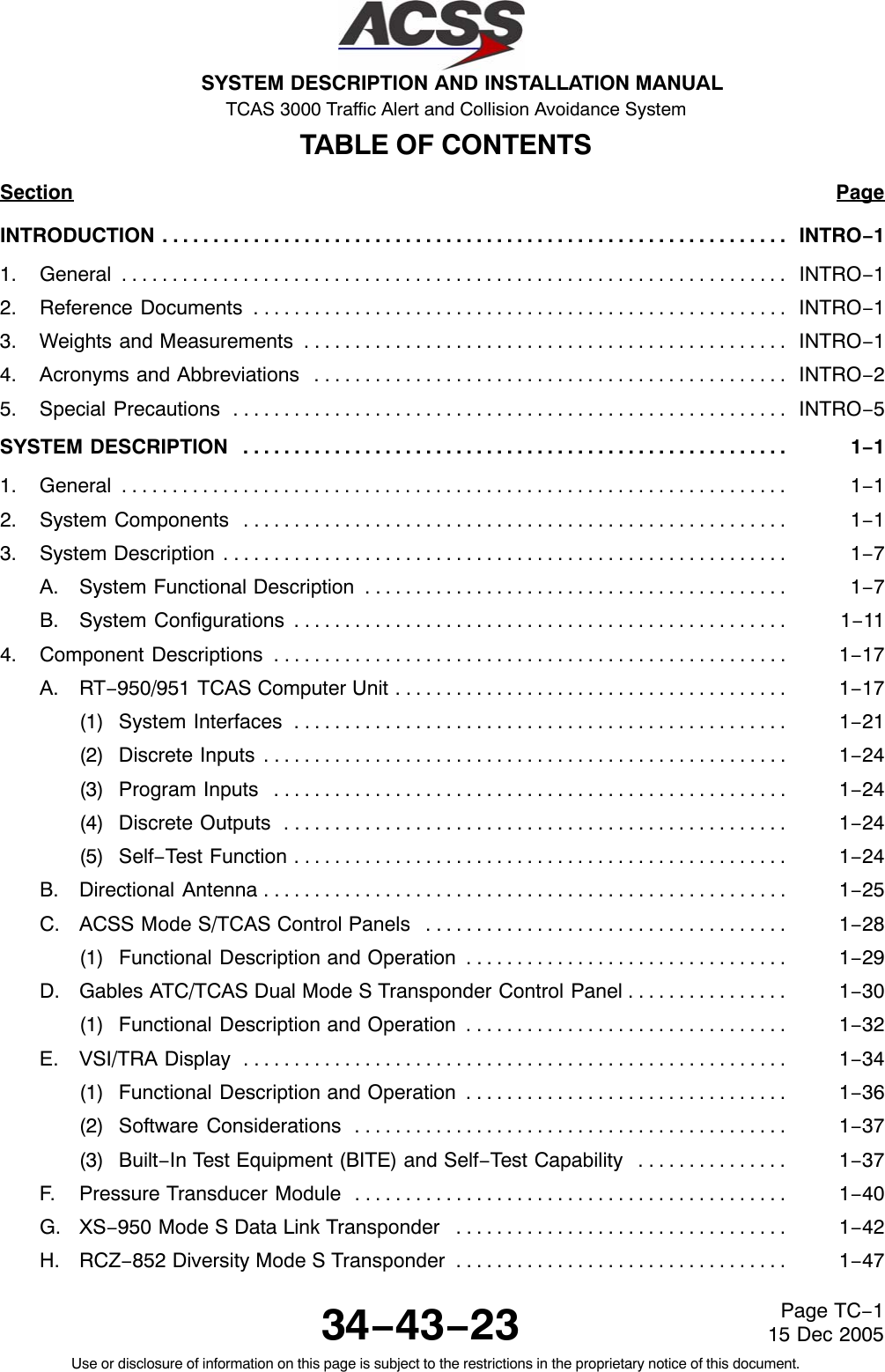

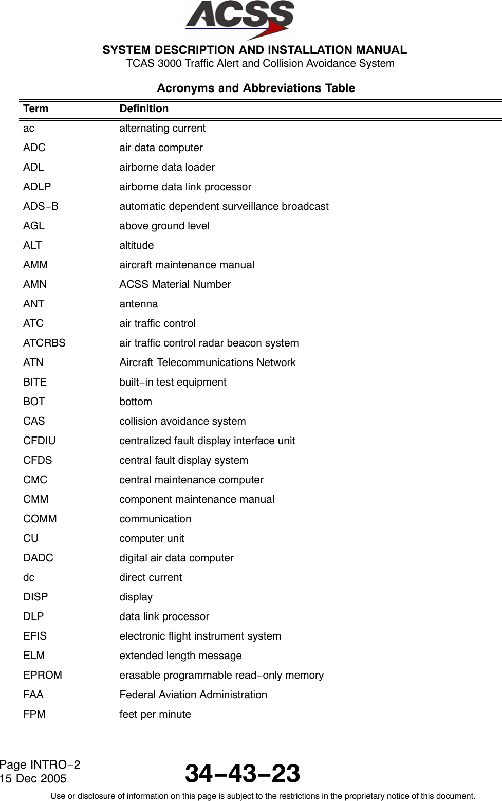

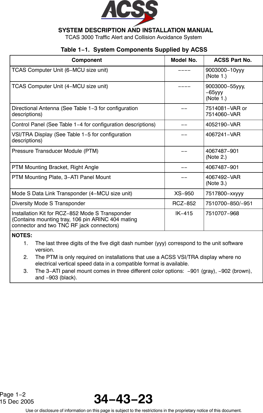

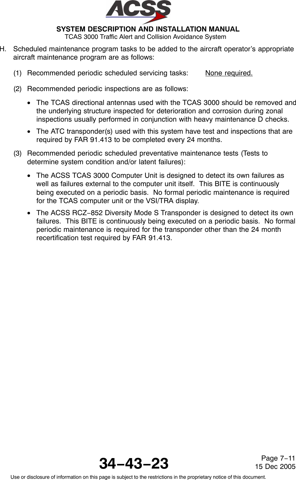
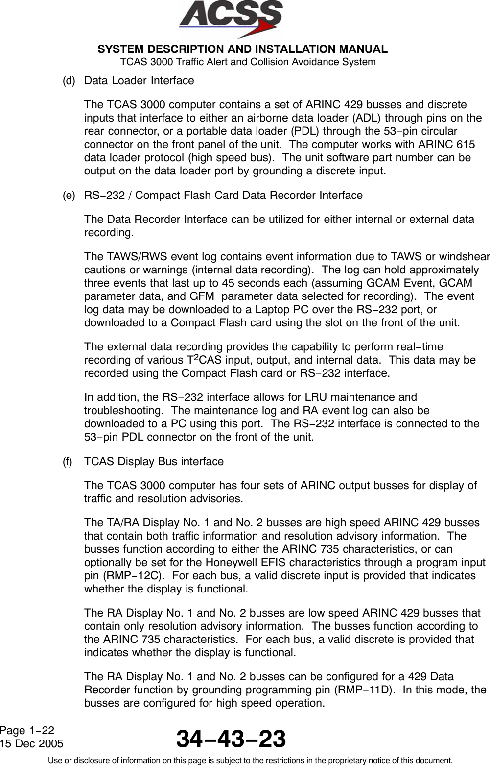
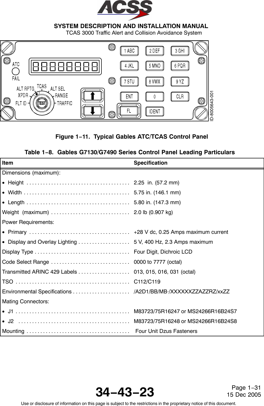
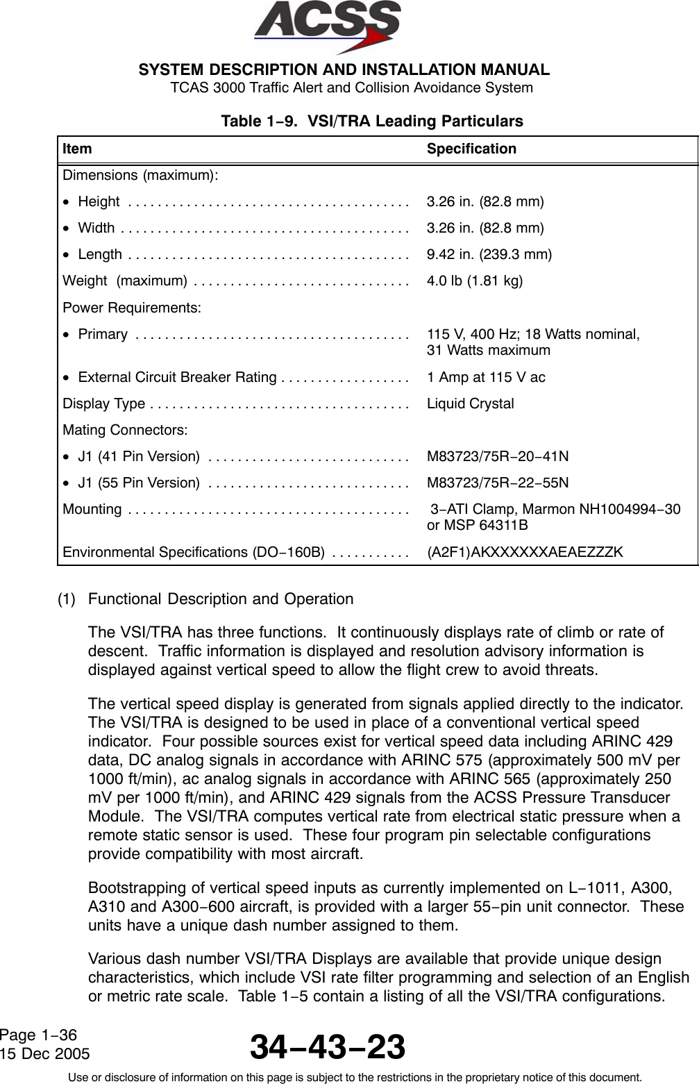
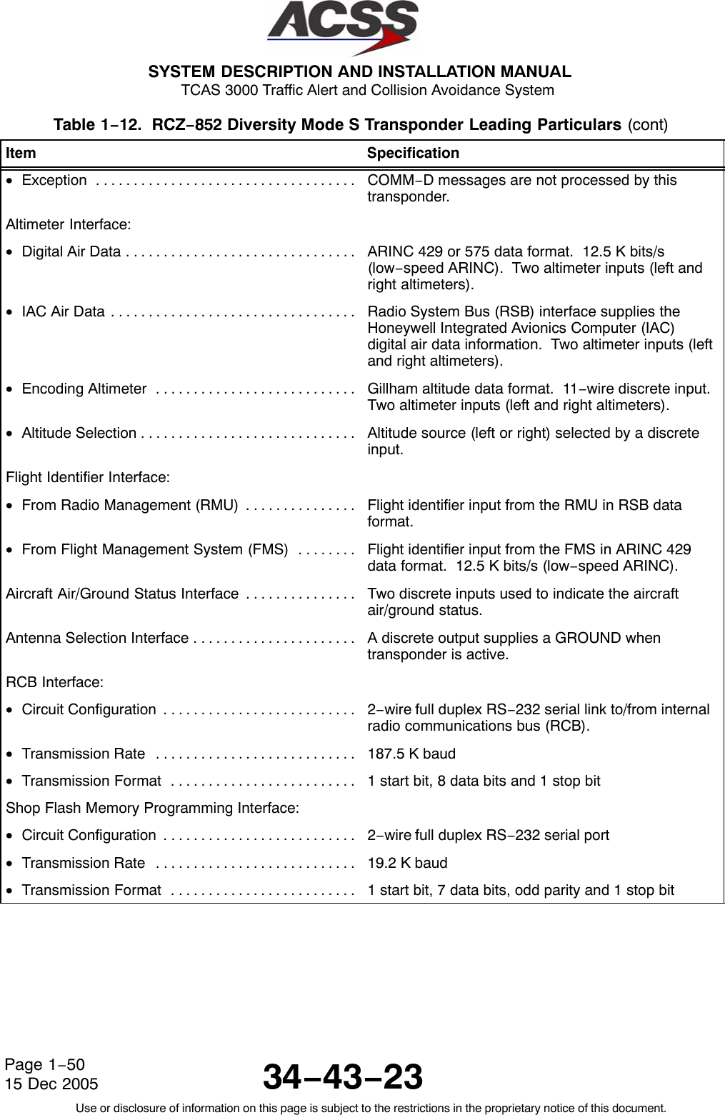
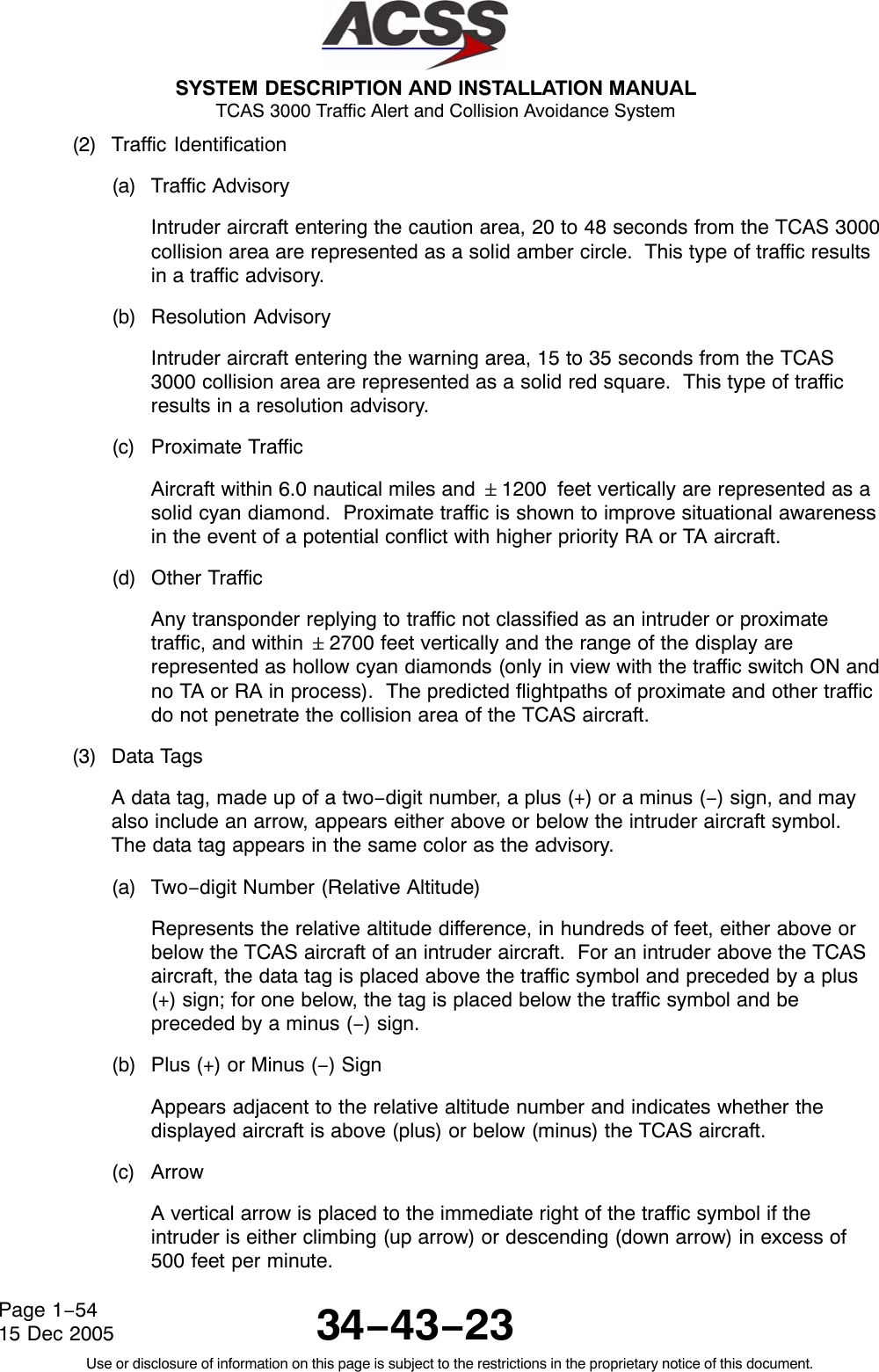
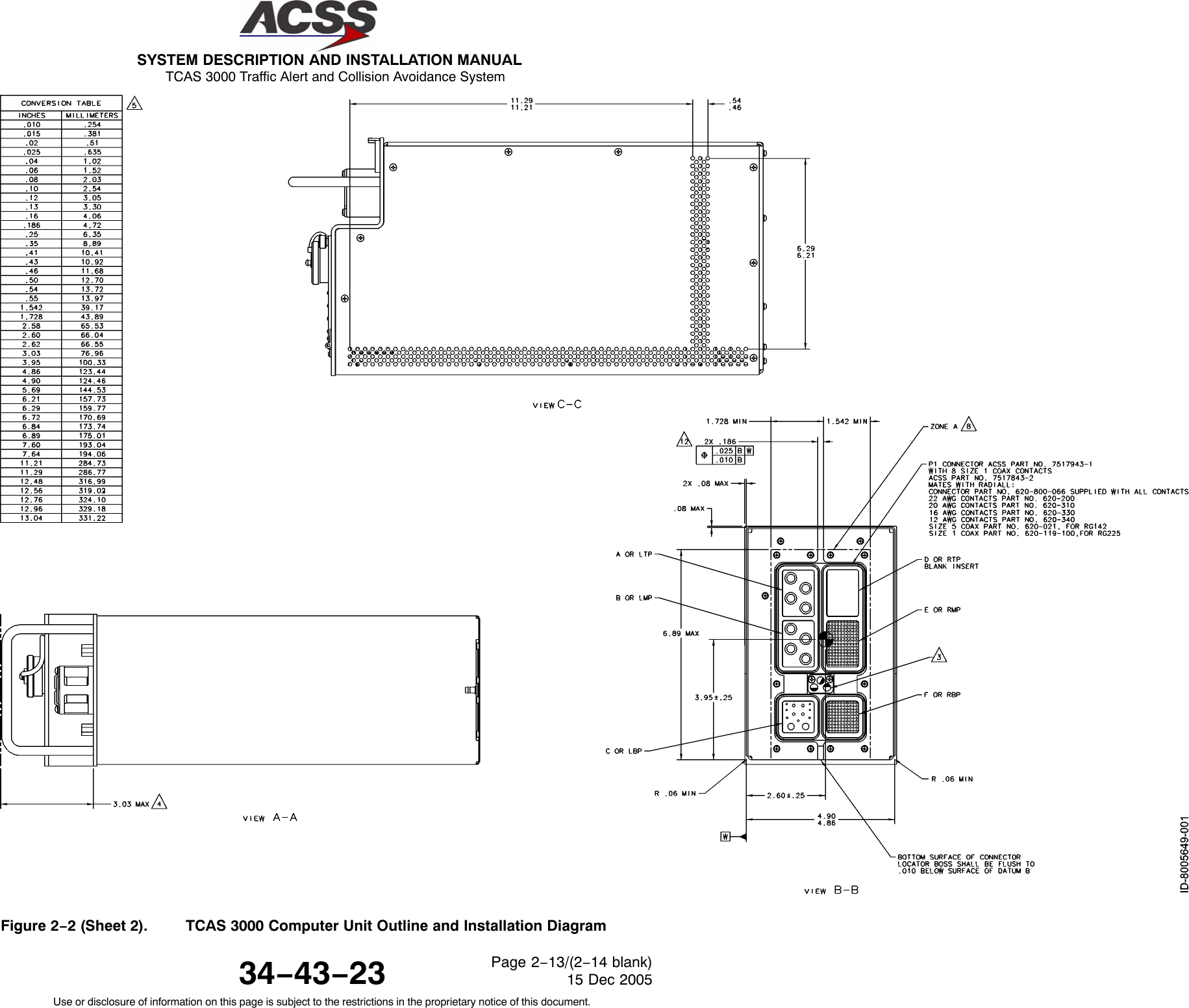
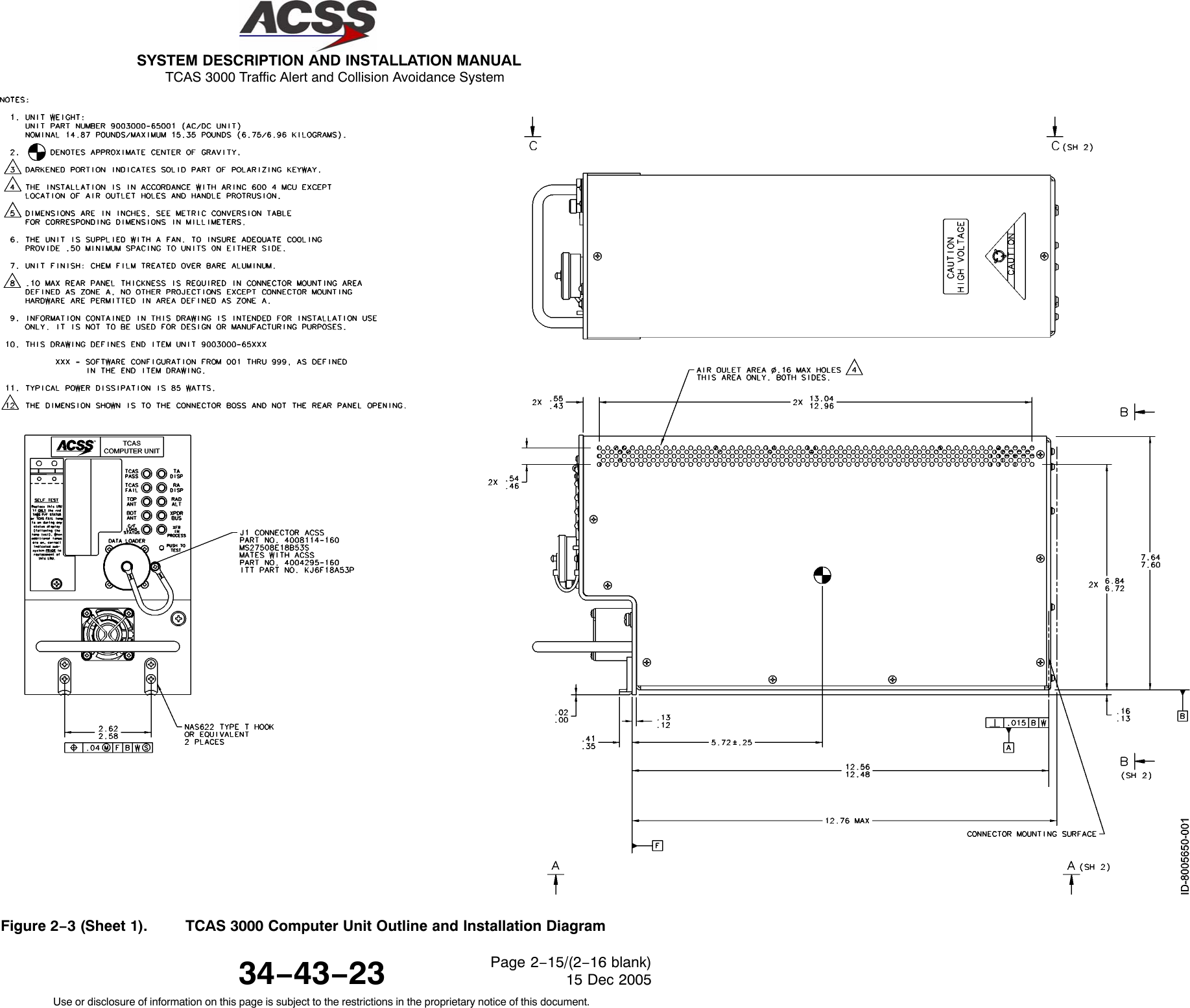
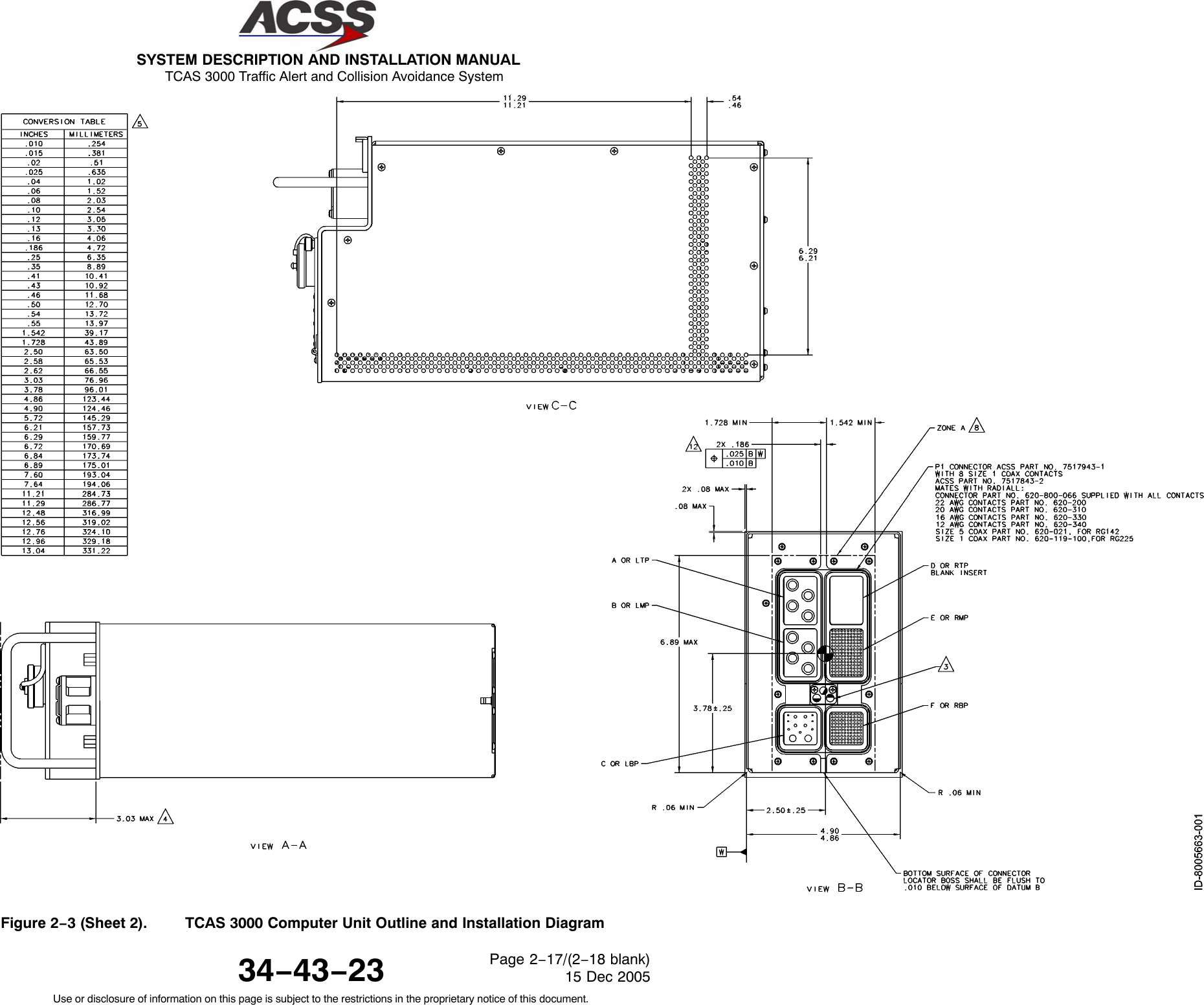
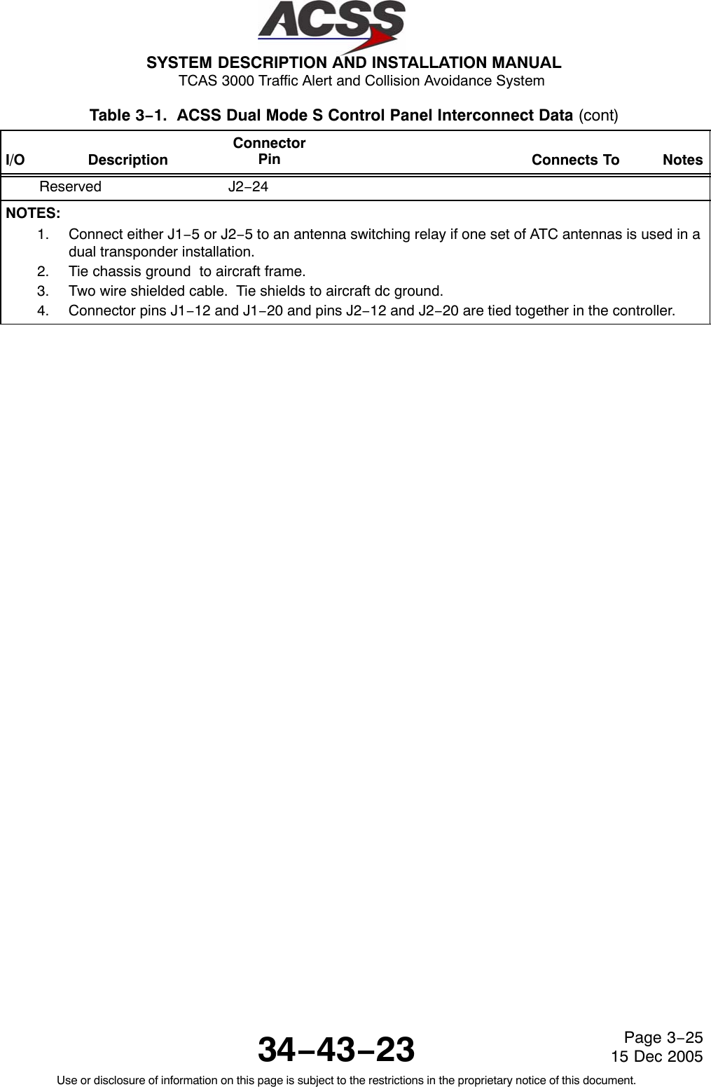
![SYSTEM DESCRIPTION AND INSTALLATION MANUAL TCAS 3000 Traffic Alert and Collision Avoidance System34−43−23Use or disclosure of information on this page is subject to the restrictions in the proprietary notice of this document.Page 1−1915 Dec 2005Table 1−6. TCAS 3000 Computer Unit Leading Particulars Item SpecificationDimensions (maximum):•Height . . . . . . . . . . . . . . . . . . . . . . . . . . . . . . . . . . . . . . . 7.64 in. (194.1 mm)•Width (4MCU) . . . . . . . . . . . . . . . . . . . . . . . . . . . . . . . . 4.90 in. (124.5 mm)•Width (6MCU) . . . . . . . . . . . . . . . . . . . . . . . . . . . . . . . . 7.52 in. (191.0 mm)•Length (4MCU) . . . . . . . . . . . . . . . . . . . . . . . . . . . . . . . 15.26 in. (387.6 mm)•Length (6MCU) . . . . . . . . . . . . . . . . . . . . . . . . . . . . . . . 15.76 in. (400.3 mm)Weight (maximum):•4MCU DC only version . . . . . . . . . . . . . . . . . . . . . . . . . 14.0 lb (6.37 kg)•4MCU DC/AC version . . . . . . . . . . . . . . . . . . . . . . . . . . •6MCU . . . . . . . . . . . . . . . . . . . . . . . . . . . . . . . . . . . . . . . 14.7 lb (6.66 kg)17.6 lb (8.00 kg)Operating Voltage:•dc Voltage . . . . . . . . . . . . . . . . . . . . . . . . . . . . . . . . . . . . +20.5 V dc minimum, +27.5 V dcnominal, +32.2 V dc maximum•ac Voltage . . . . . . . . . . . . . . . . . . . . . . . . . . . . . . . . . . . . 97 V rms minimum, 115 V rms nominal,134 V rms maximum at 400 80 HzPower Consumption . . . . . . . . . . . . . . . . . . . . . . . . . . . . . 70 Watts standby, 100 Watts maximumCircuit Breaker Ratings:•115 V ac Circuit Breaker . . . . . . . . . . . . . . . . . . . . . . . 5 Amp Typical•28 V dc Circuit Breaker . . . . . . . . . . . . . . . . . . . . . . . . 10 Amp TypicalMating Connector:•P1 (Rear Connector) . . . . . . . . . . . . . . . . . . . . . . . . . . . Radial Part No. 620−800−066•J1 (Front Connector) . . . . . . . . . . . . . . . . . . . . . . . . . . ACSS Part No. 4004295−160, ITT Part No. KJ6F18A53PMounting: •6MCU . . . . . . . . . . . . . . . . . . . . . . . . . . . . . . . . . . . . . . . ARINC 600 6−MCU Tray Assembly•4MCU . . . . . . . . . . . . . . . . . . . . . . . . . . . . . . . . . . . . . . . ARINC 600 4−MCU Tray AssemblyTSO:•All units . . . . . . . . . . . . . . . . . . . . . . . . . . . . . . . . . . . . . . C119bETSO . . . . . . . . . . . . . . . . . . . . . . . . . . . . . . . . . . . . . . . . . . C119bSoftware Development Specification . . . . . . . . . . . . . . . DO−178B, Level BEnvironmental Specifications . . . . . . . . . . . . . . . . . . . . . . DO−160D Environmental Category[A2F2]YBB [CLMY][E1]XXXXXZ[EBZ]A[EZ]ZRZA3EXX](https://usermanual.wiki/ACSS-an-L-3-Communications-and-Thales/T3K-4M/User-Guide-718711-Page-46.png)
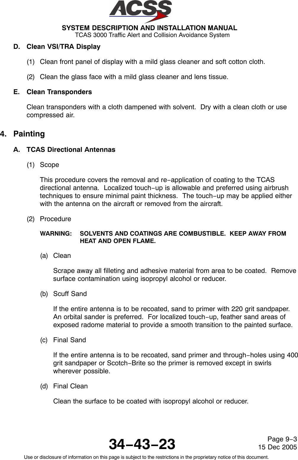
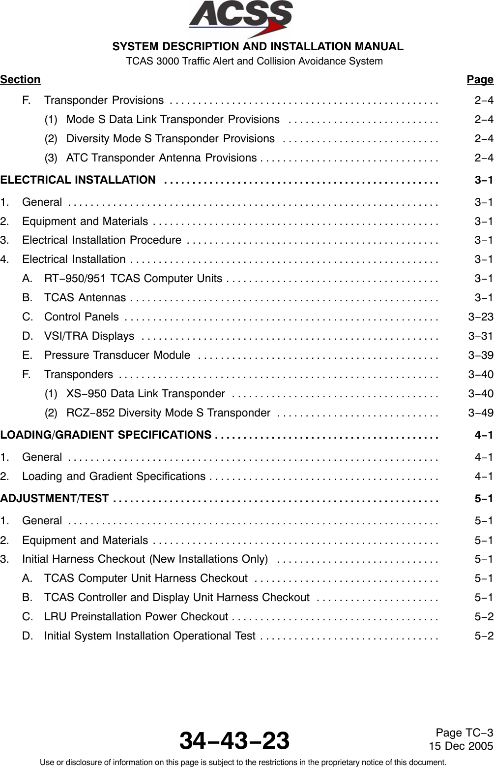
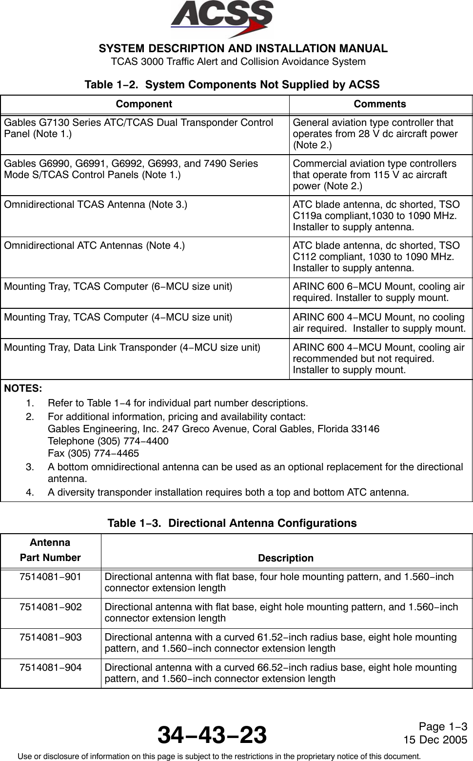
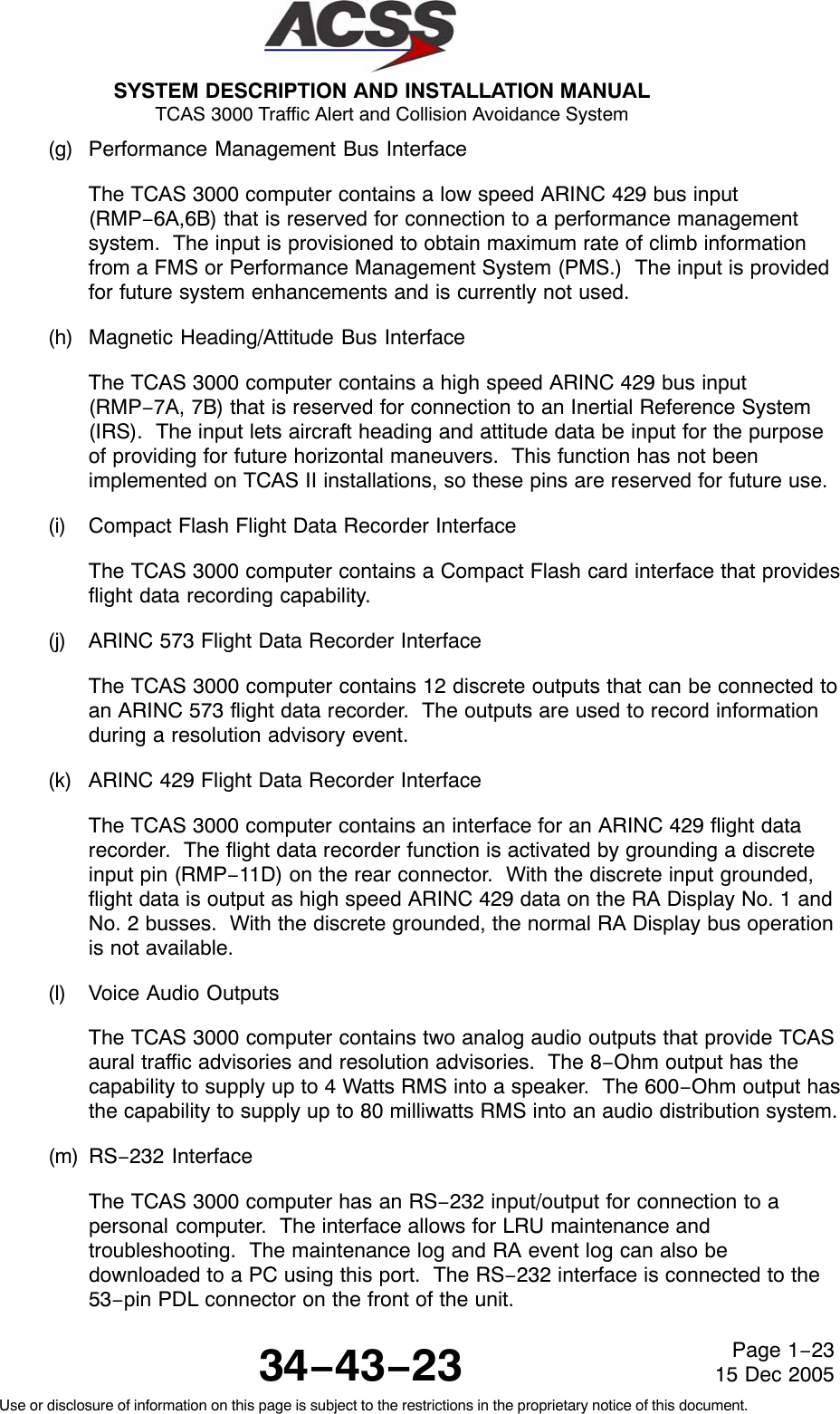
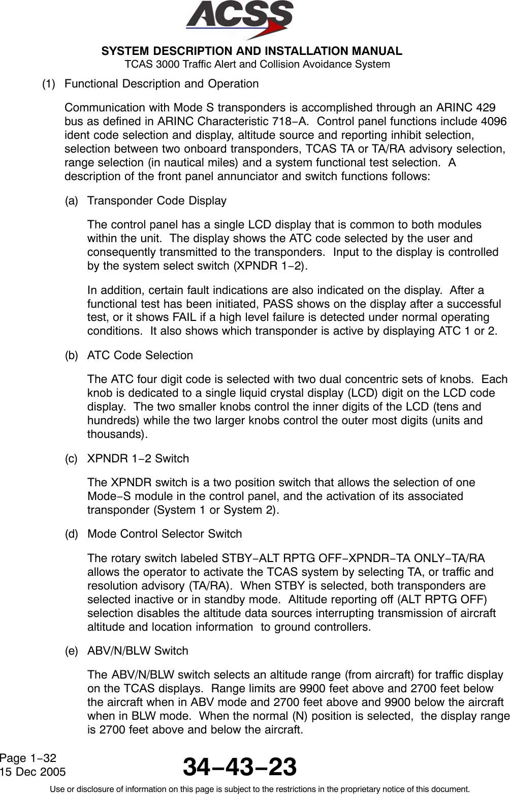
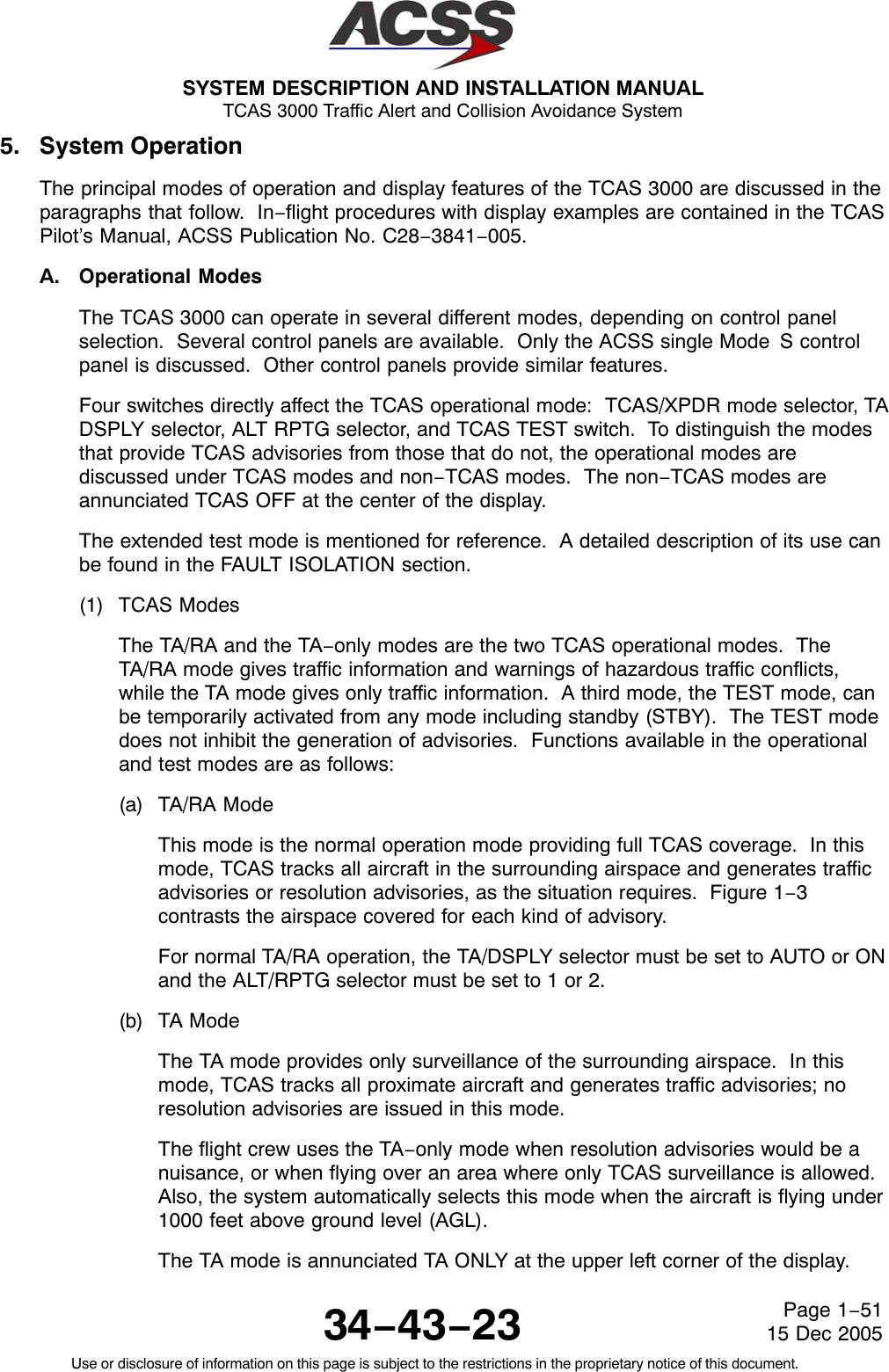
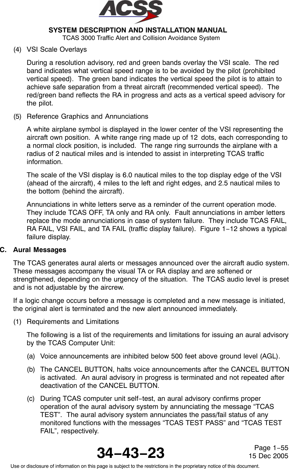
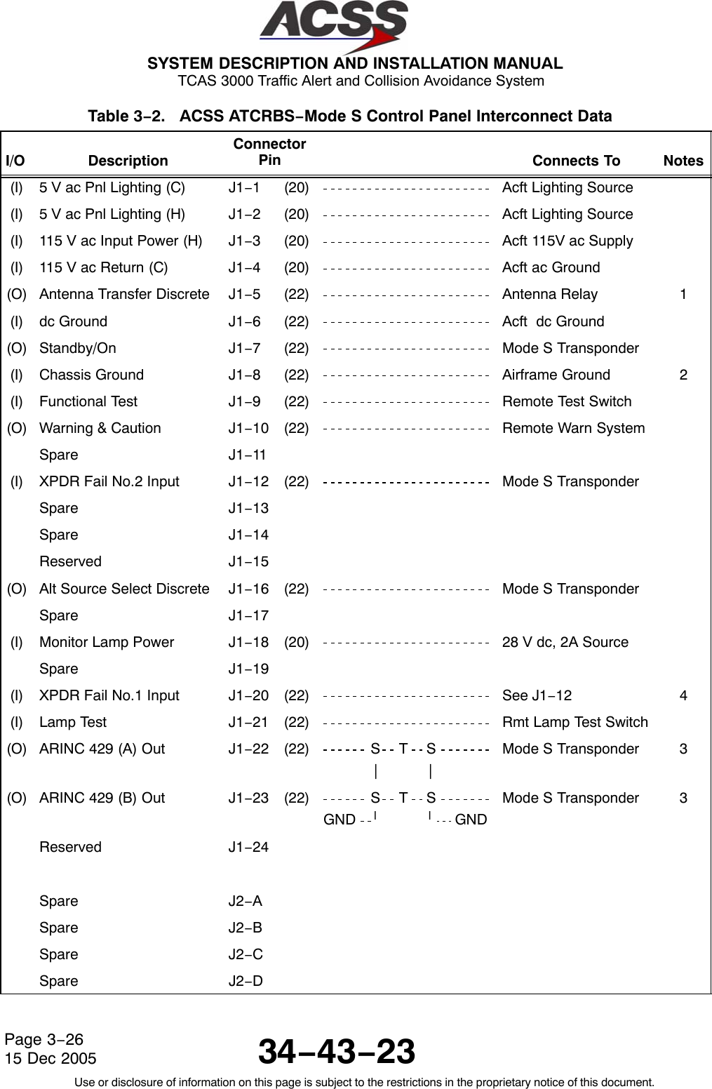
![SYSTEM DESCRIPTION AND INSTALLATION MANUAL TCAS 3000 Traffic Alert and Collision Avoidance System34−43−23Use or disclosure of information on this page is subject to the restrictions in the proprietary notice of this document.Page 1−2015 Dec 2005Table 1−6. TCAS 3000 Computer Unit Leading Particulars (cont)Item Specification•Temperature / Altitude [A2F2]:−Operating Temperature . . . . . . . . . . . . . . . . . . . . . . −55 to +70 degrees C−Ground Survival Temperature . . . . . . . . . . . . . . . . −55 to +85 degrees C−Altitude . . . . . . . . . . . . . . . . . . . . . . . . . . . . . . . . . . . . Sea Level to 55,000 feet−Loss of Cooling . . . . . . . . . . . . . . . . . . . . . . . . . . . . . +40 degrees C for 300 minutes minimumRF Transmitter Characteristics:•Transmitter Frequency . . . . . . . . . . . . . . . . . . . . . . . . . 1030 ± 0.01 MHz•RF Peak Output Power:−Minimum . . . . . . . . . . . . . . . . . . . . . . . . . . . . . . . . . . . 53.3 dBm (210 Watts)−Nominal . . . . . . . . . . . . . . . . . . . . . . . . . . . . . . . . . . . 55.3 dBm (335 Watts)−Maximum . . . . . . . . . . . . . . . . . . . . . . . . . . . . . . . . . . 57.3 dBm (540 Watts)•Unwanted Output Power in an Inactive State . . . . . . −72 dBm•Pulse Timing Characteristics:−Pulse Rise Time . . . . . . . . . . . . . . . . . . . . . . . . . . . . 0.05 to 0.10 microseconds−Pulse Fall Time . . . . . . . . . . . . . . . . . . . . . . . . . . . . . 0.05 to 0.20 microseconds− ATCRBS S1, P1, P3, P4 Duration . . . . . . . . . . . . 0.08 ± 0.05 microseconds−Mode S P1, P2 Duration . . . . . . . . . . . . . . . . . . . . . 0.08 ± 0.05 microseconds−Mode S P6 Duration . . . . . . . . . . . . . . . . . . . . . . . . 16.25 ± 0.125 microseconds (short)30.25 ± 0.125 microseconds (long)•Whisper−Shout Characteristics:−Range . . . . . . . . . . . . . . . . . . . . . . . . . . . . . . . . . . . . . 0 to 26 dB attenuation by 1 dB steps−Absolute Tolerance . . . . . . . . . . . . . . . . . . . . . . . . . . Relative to the 0 dB step, the attenuationof each step does not exceed thenominal attenuation by more than ±2 dB−Relative Tolerance . . . . . . . . . . . . . . . . . . . . . . . . . . Step increments are ±0.5 dB andmonotonicRF Receiver Characteristics:•Receiver Frequency Range . . . . . . . . . . . . . . . . . . . . . 1087 to 1093 MHz•Receiver MTL Over Frequency . . . . . . . . . . . . . . . . . . (Normal Operation)−77 ± 2 dBm (≥90% Mode S andATCRBS replies decoded)•Receiver Dynamic Range . . . . . . . . . . . . . . . . . . . . . . (Normal Operation)−77 to −23 dBm (≥99% Mode S andATCRBS replies for signal levels greaterthan MTL +3 dB)](https://usermanual.wiki/ACSS-an-L-3-Communications-and-Thales/T3K-4M/User-Guide-718711-Page-47.png)
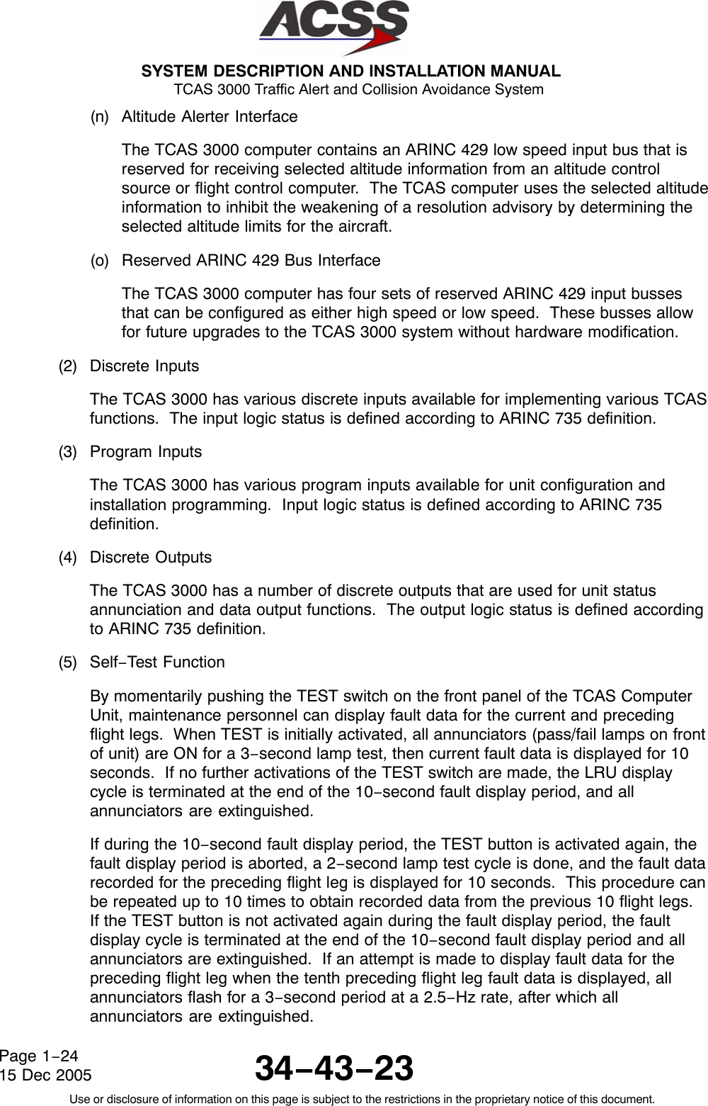

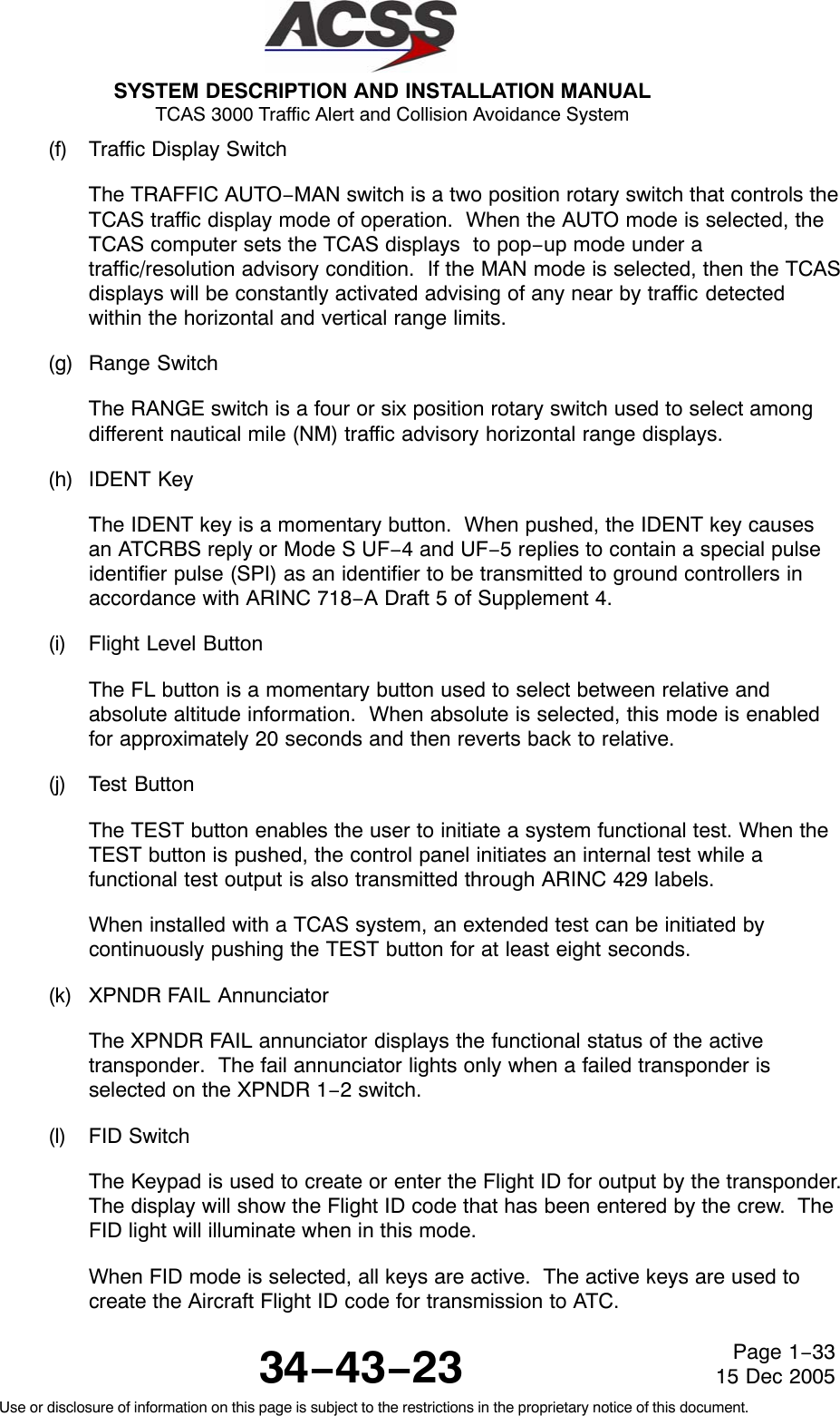
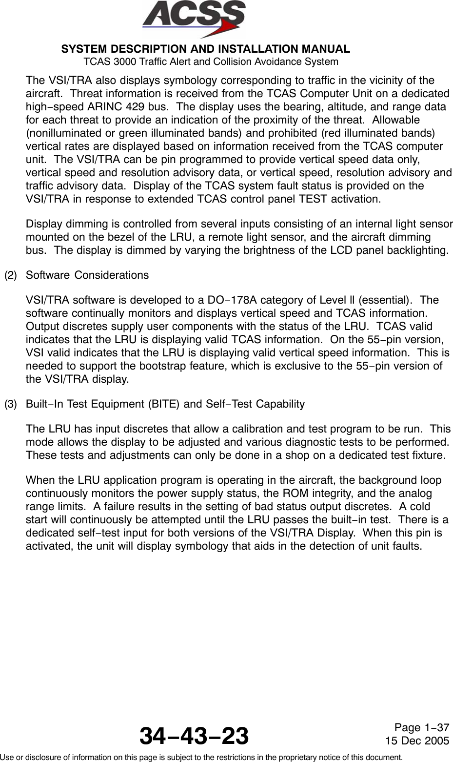
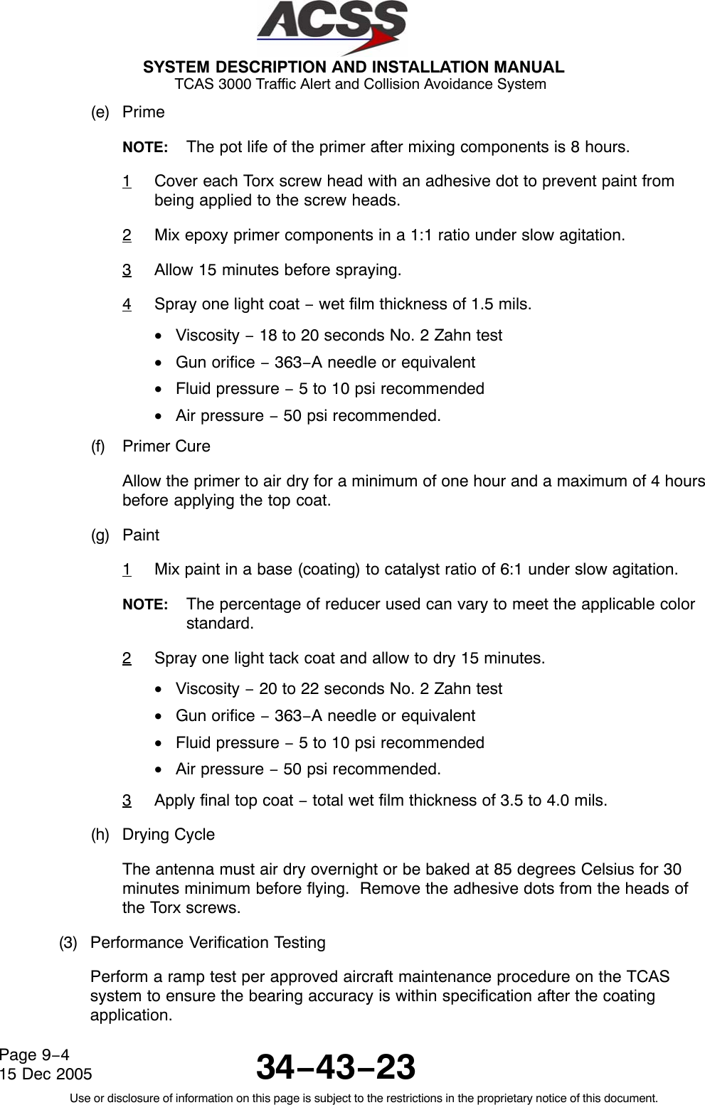
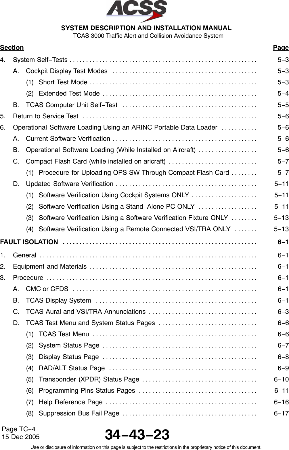
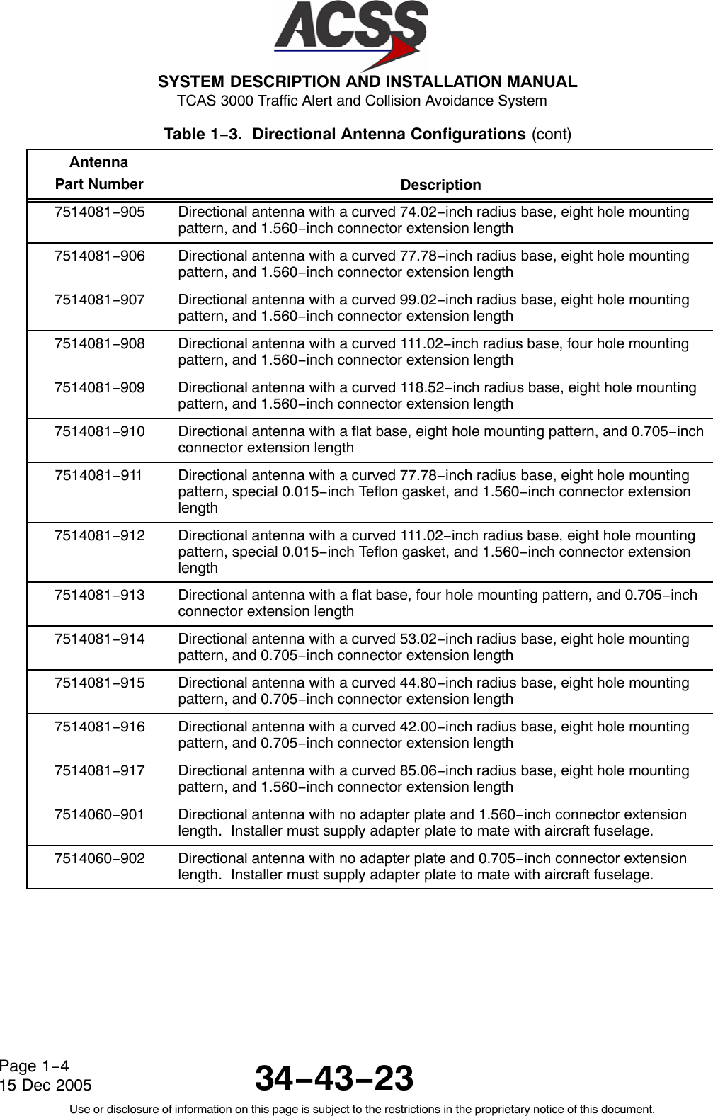
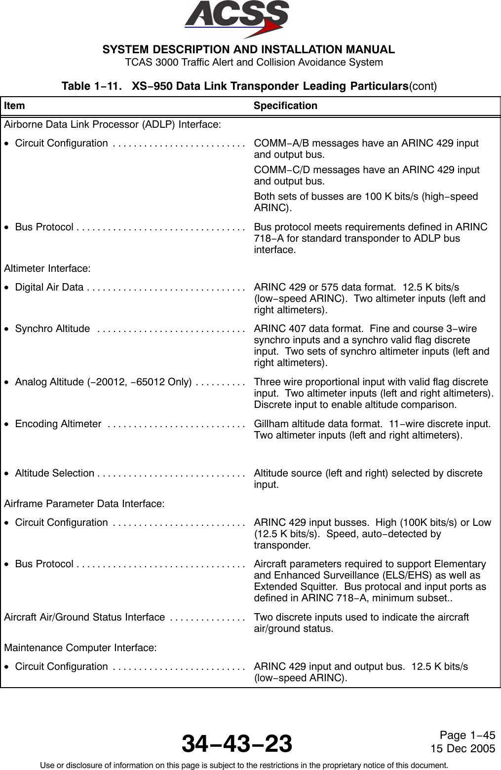
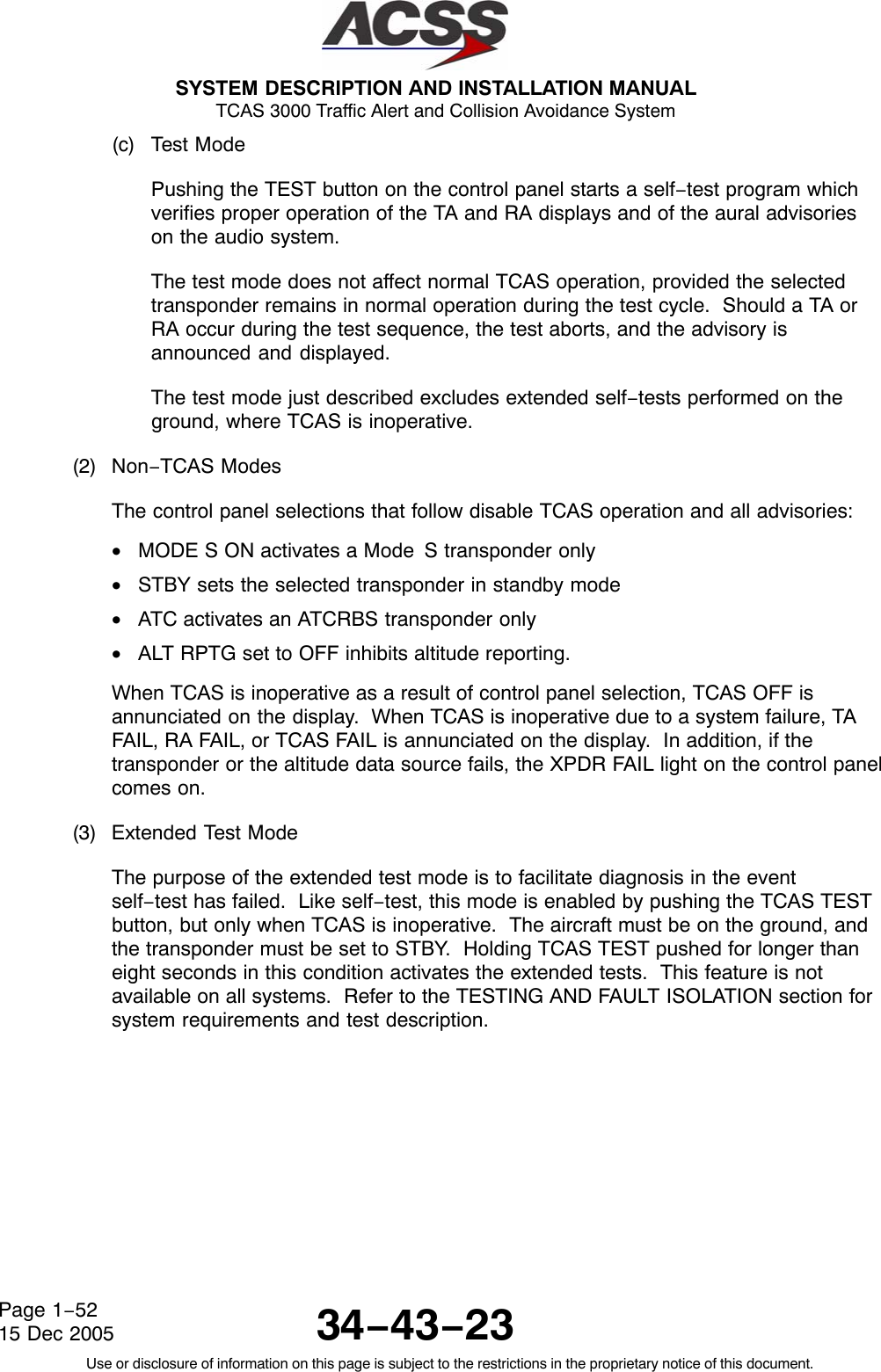
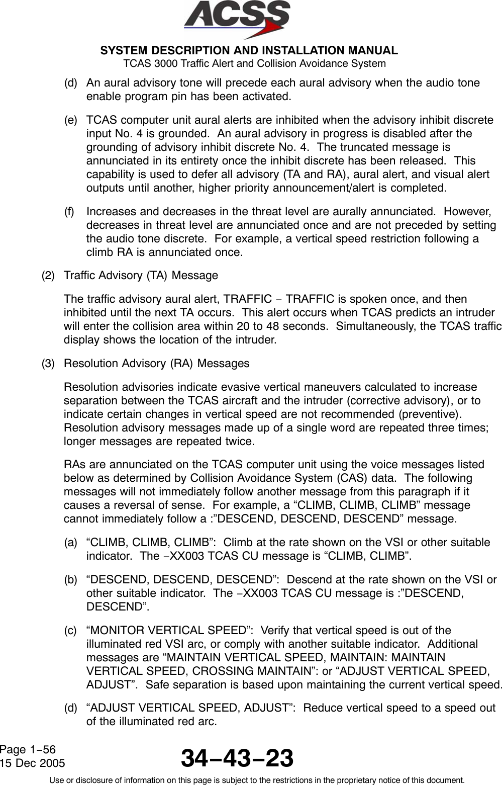
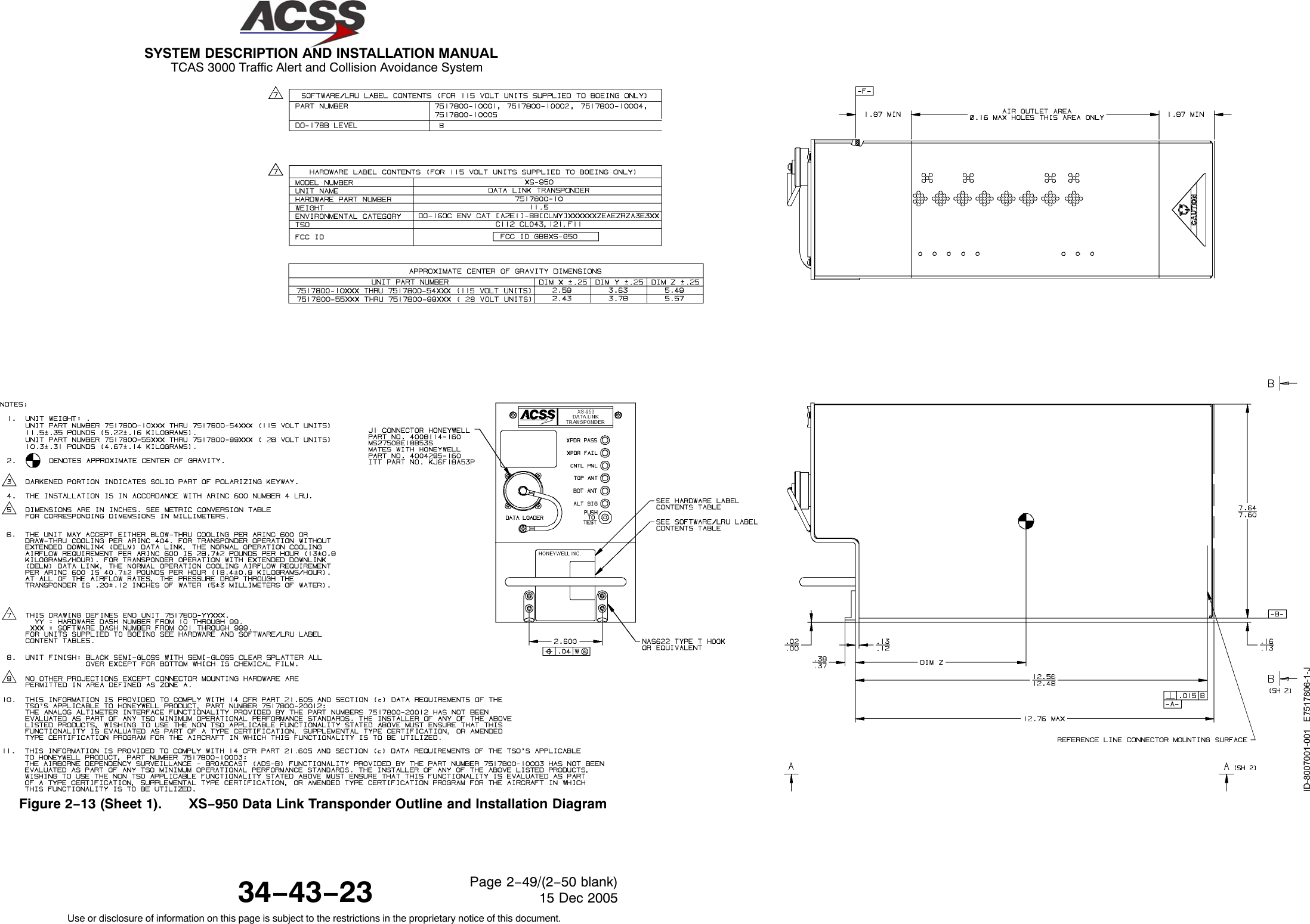
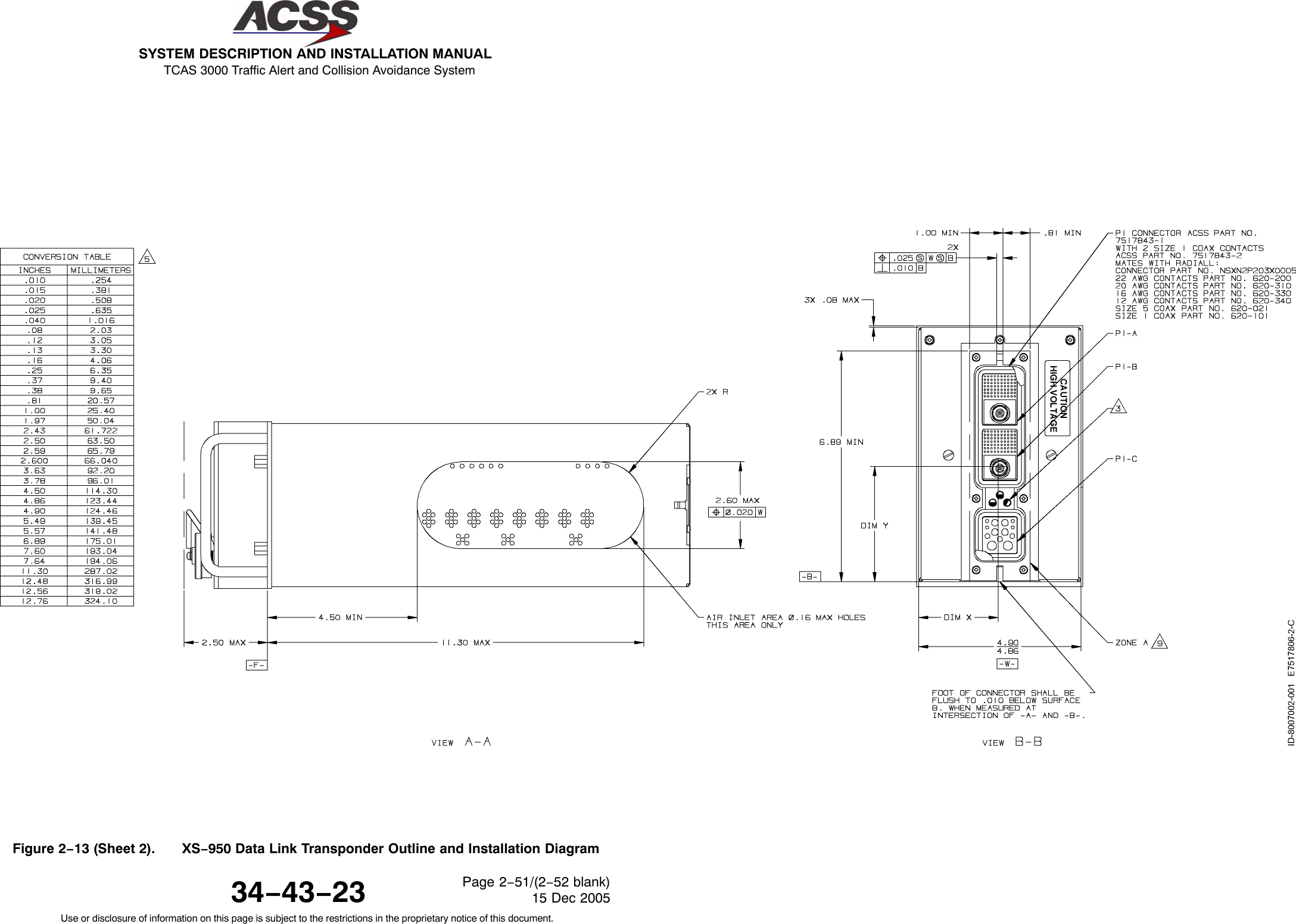
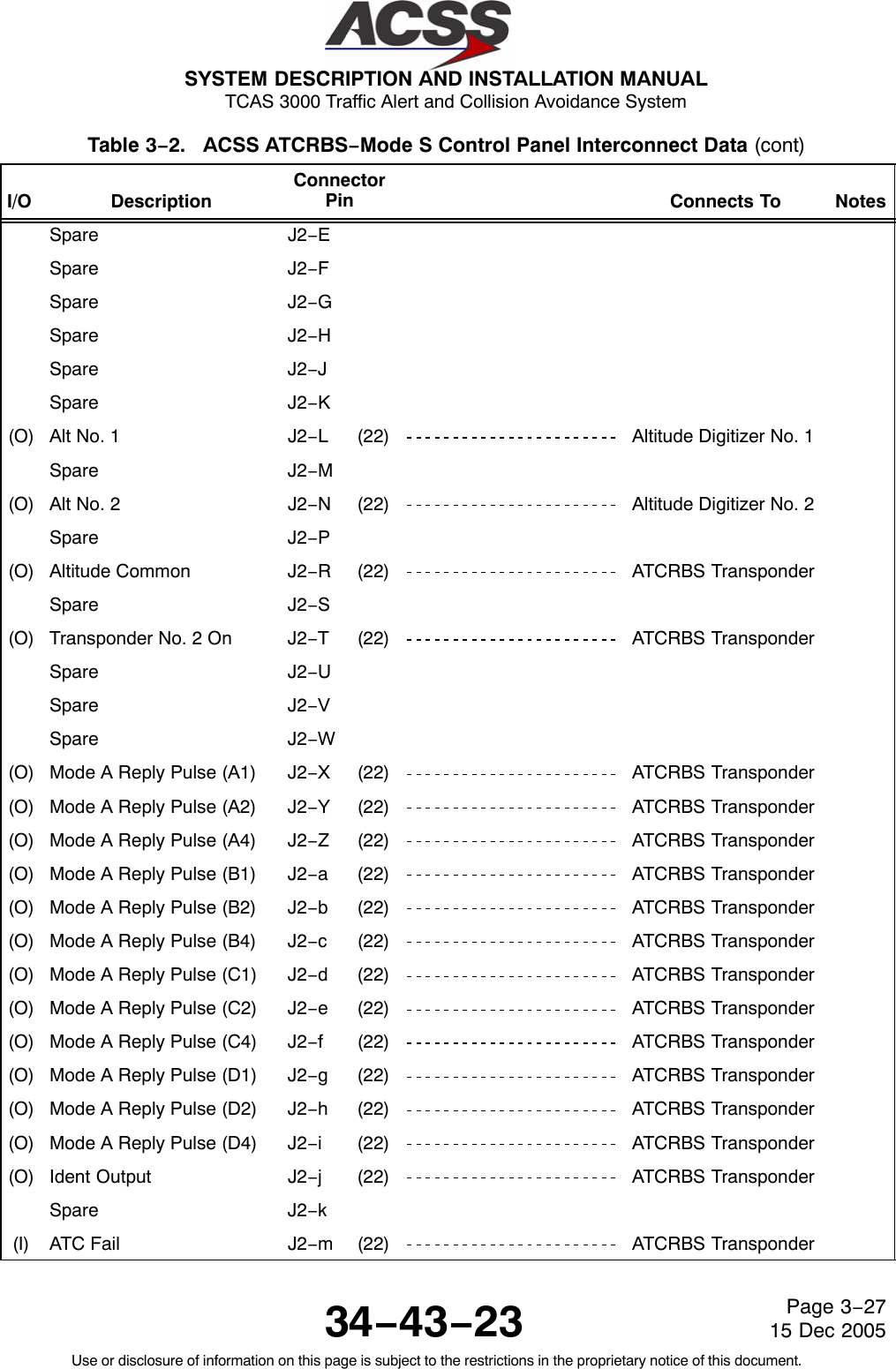
![SYSTEM DESCRIPTION AND INSTALLATION MANUAL TCAS 3000 Traffic Alert and Collision Avoidance System34−43−23Use or disclosure of information on this page is subject to the restrictions in the proprietary notice of this document.Page 1−4315 Dec 2005Table 1−11. XS−950 Data Link Transponder Leading Particulars Item SpecificationDimensions (maximum):•Height . . . . . . . . . . . . . . . . . . . . . . . . . . . . . . . . . . . . . . 7.6 in. (192 mm)•Width . . . . . . . . . . . . . . . . . . . . . . . . . . . . . . . . . . . . . . 4.9 in. (124.5 mm)•Length . . . . . . . . . . . . . . . . . . . . . . . . . . . . . . . . . . . . . 15.2 in. (386 mm)Weight . . . . . . . . . . . . . . . . . . . . . . . . . . . . . . . . . . . . . . . 11.5 lb (5.2 kg)Power Requirements (115 V ac version):•Operating Voltage . . . . . . . . . . . . . . . . . . . . . . . . . . . . 97 to 134 V rms, 115 V rms nominal•Operating Frequency . . . . . . . . . . . . . . . . . . . . . . . . . 320 to 480 Hz, 400 Hz nominal•Power Consumption:− Standby Mode (No Replies) . . . . . . . . . . . . . . . . . 40 Watts maximum− Active mode (Maximum Load) . . . . . . . . . . . . . . . 85 Watts maximum•External Circuit Breaker Rating . . . . . . . . . . . . . . . . . 5 A at 115 V ac, 400 HzPower Requirements (28 V dc version):•Operating Voltage . . . . . . . . . . . . . . . . . . . . . . . . . . . . +18.0 to +32.2 V dc, +27.5 V dc nominal•Power Consumption:−Standby Mode (No Replies) . . . . . . . . . . . . . . . . . 40 Watts maximum−Active mode (Maximum Load) . . . . . . . . . . . . . . . 85 Watts maximum•External Circuit Breaker Rating . . . . . . . . . . . . . . . . . 7 A at 28 V dcMating Connector . . . . . . . . . . . . . . . . . . . . . . . . . . . . . . Radial Part No. NSXN2P203X0005Mounting . . . . . . . . . . . . . . . . . . . . . . . . . . . . . . . . . . . . . . ARINC 600 4MCU Tray AssemblyTSO . . . . . . . . . . . . . . . . . . . . . . . . . . . . . . . . . . . . . . . . . . C112, CL043, 121, F11Environmental Specifications: . . . . . . . . . . . . . . . . . . . . DO−160C Environmental Category−115 V ac version . . . . . . . . . . . . . . . . . . . . . . . . . . . [A2E1]−BB[CLMY]XXXXXXZEAEZRZA3E3XX−28 V dc version . . . . . . . . . . . . . . . . . . . . . . . . . . . [A2E1]−BB[CLMY]XXXXXXZ[BZ]AZZRZA3E3XX•Temperature / Altitude [A2E1]:−Operating Temperature . . . . . . . . . . . . . . . . . . . . . −55 to +70 degrees C−Ground Survival Temperature . . . . . . . . . . . . . . . −55 to +85 degrees C−Altitude . . . . . . . . . . . . . . . . . . . . . . . . . . . . . . . . . . . Sea Level to 70,000 feet−Loss of Cooling . . . . . . . . . . . . . . . . . . . . . . . . . . . . +40 degrees C for 30 minutes minimum](https://usermanual.wiki/ACSS-an-L-3-Communications-and-Thales/T3K-4M/User-Guide-718711-Page-70.png)
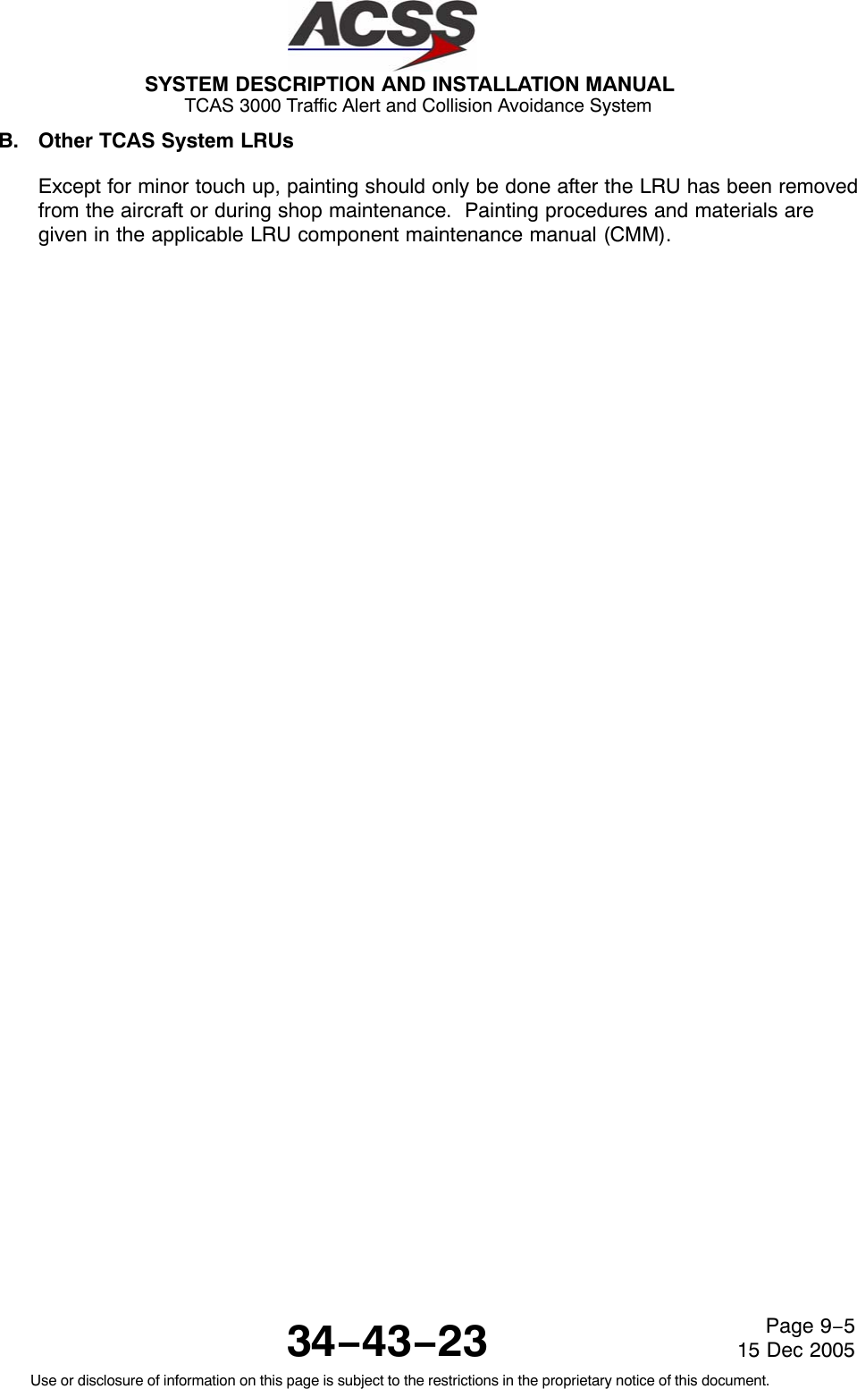
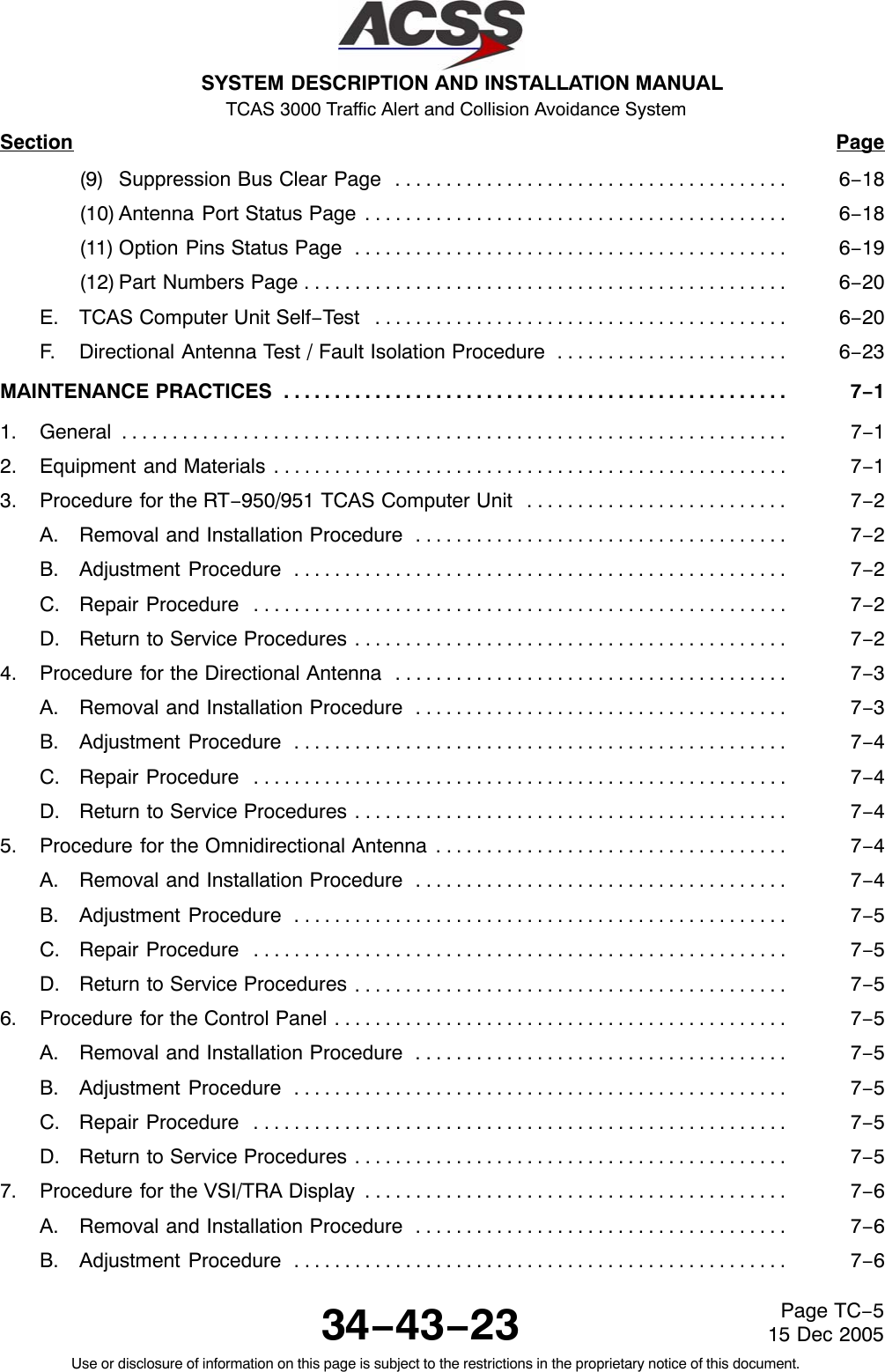
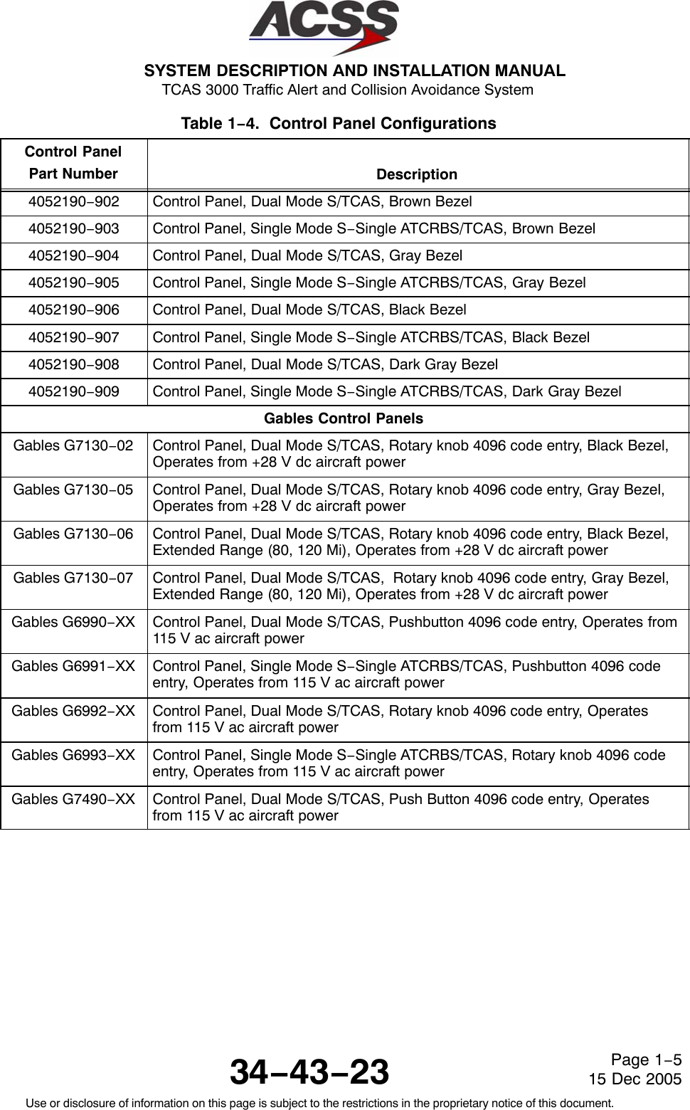
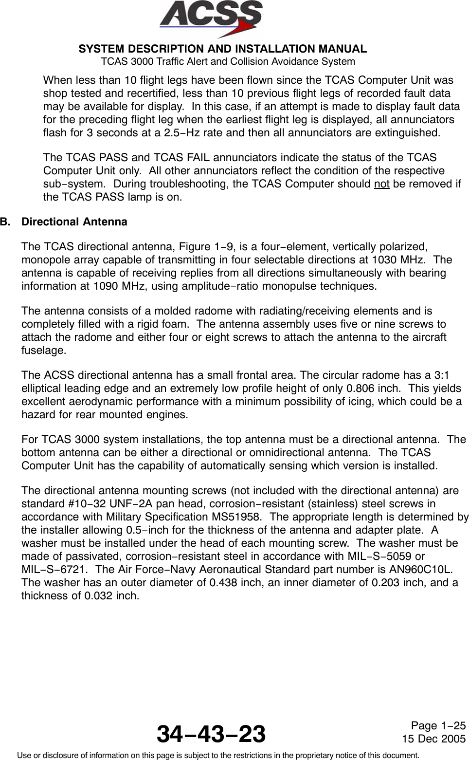
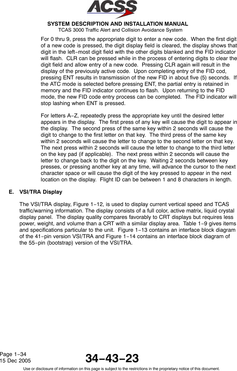
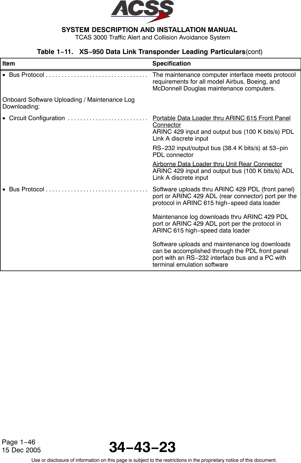
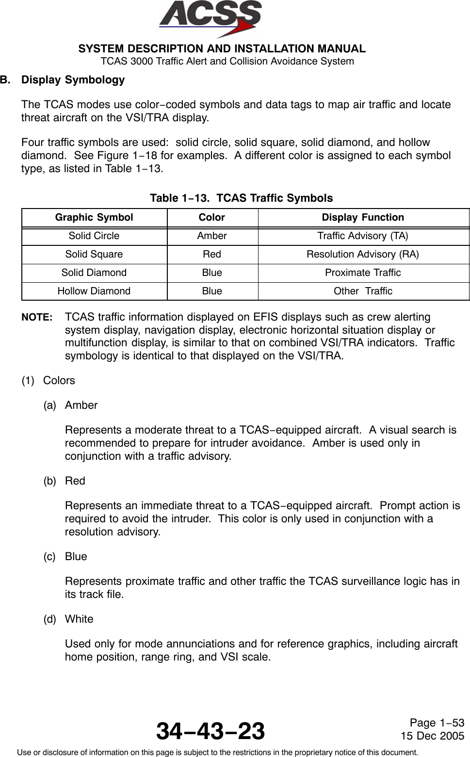
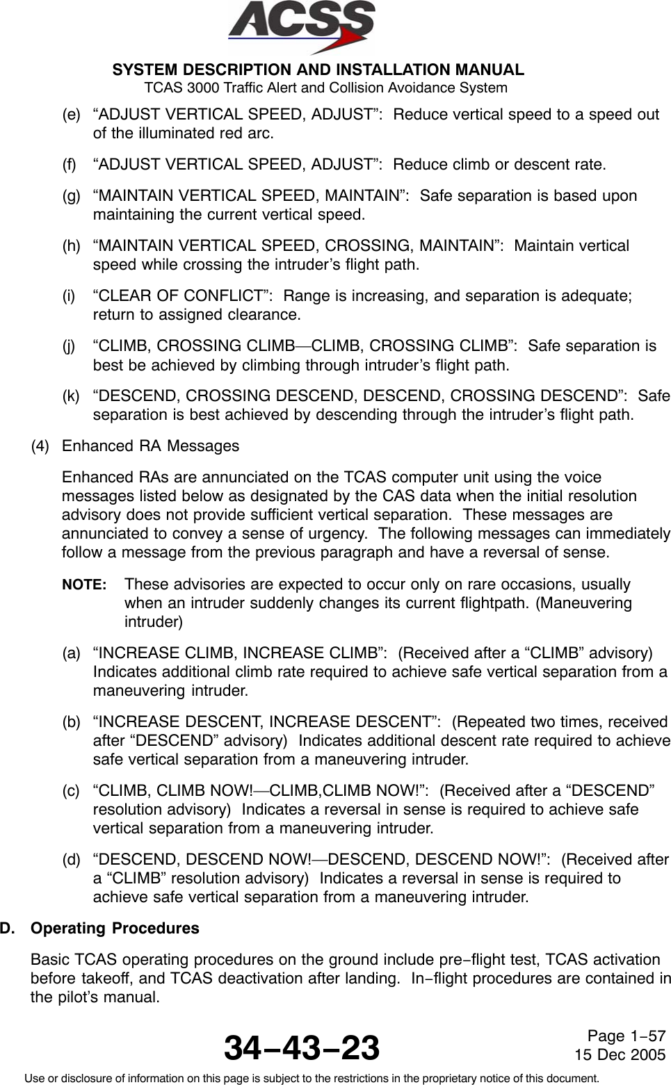
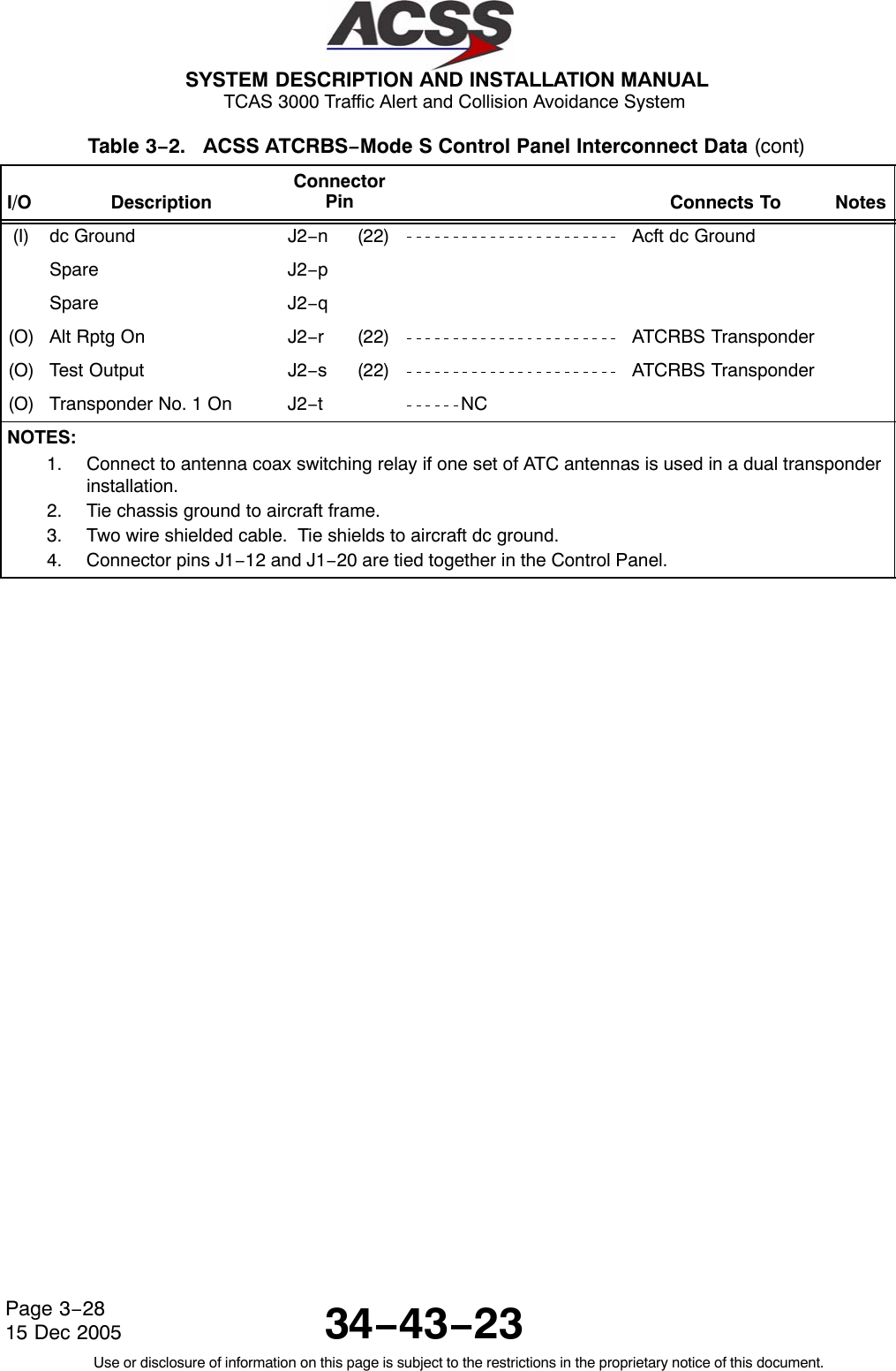
![SYSTEM DESCRIPTION AND INSTALLATION MANUAL TCAS 3000 Traffic Alert and Collision Avoidance System34−43−23Use or disclosure of information on this page is subject to the restrictions in the proprietary notice of this document.Page 1−4415 Dec 2005Table 1−11. XS−950 Data Link Transponder Leading Particulars(cont)Item Specification•Vibration [CLMY]:− Category C . . . . . . . . . . . . . . . . . . . . . . . . . . . . . . . Fixed wing turbojet engine, fuselage mounting− Category L . . . . . . . . . . . . . . . . . . . . . . . . . . . . . . . Fixed wing reciprocating and turboprop multi andsingle engine over 12,500 pounds, fuselagemounting− Category M . . . . . . . . . . . . . . . . . . . . . . . . . . . . . . . Fixed wing reciprocating and turboprop multi andsingle engine less than 12,500 pounds, instrumentpanel/console and equipment rack mounting− Category Y . . . . . . . . . . . . . . . . . . . . . . . . . . . . . . . Helicopter, reciprocating and turbojet, fuselagemountingOperating Modes:•STANDBY . . . . . . . . . . . . . . . . . . . . . . . . . . . . . . . . . . . Ready but not replying•ATC ON . . . . . . . . . . . . . . . . . . . . . . . . . . . . . . . . . . . . Transponder Modes A and S, no altitude reporting•ATC ALT . . . . . . . . . . . . . . . . . . . . . . . . . . . . . . . . . . . Transponder Modes A, C, and S. Altitude reportingis enabledTransmitter Frequency . . . . . . . . . . . . . . . . . . . . . . . . . 1090 ±1.0 MHzTransmitter Power . . . . . . . . . . . . . . . . . . . . . . . . . . . . . 640 Watts maximum peak pulse, 250 WattsminimumReceiver Frequency . . . . . . . . . . . . . . . . . . . . . . . . . . . . 1030 MHzMinimum Trigger Level (MTL) . . . . . . . . . . . . . . . . . . . . −76 ± 3 dBmMutual Suppression . . . . . . . . . . . . . . . . . . . . . . . . . . . . Bidirectional, accepts +18 to +70 volt pulse input;provides +28 volt nominal outputController Interface:•Circuit Configuration . . . . . . . . . . . . . . . . . . . . . . . . . . Two ARINC 429 control data input ports. 12.5 Kbits/s (low−speed ARINC)•Bus Protocol . . . . . . . . . . . . . . . . . . . . . . . . . . . . . . . . . Bus protocol meets requirements defined in ARINC718−A for receiving transponder and TCAS controlinformation.TCAS II Interface:•Circuit Configuration . . . . . . . . . . . . . . . . . . . . . . . . . . ARINC 429 input and output bus. 100 K bits/s(high−speed ARINC)•Bus Protocol . . . . . . . . . . . . . . . . . . . . . . . . . . . . . . . . . Bus protocol meets requirements defined in ARINC718−A and ARINC 735A−1 for standard transponderto TCAS interface](https://usermanual.wiki/ACSS-an-L-3-Communications-and-Thales/T3K-4M/User-Guide-718711-Page-71.png)
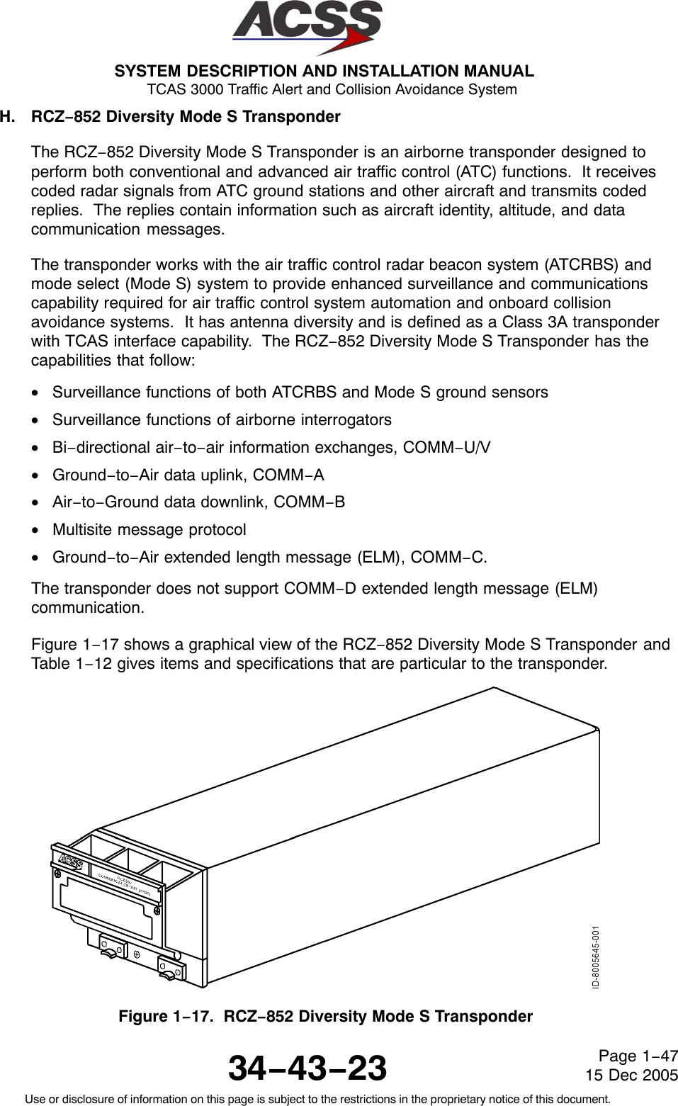
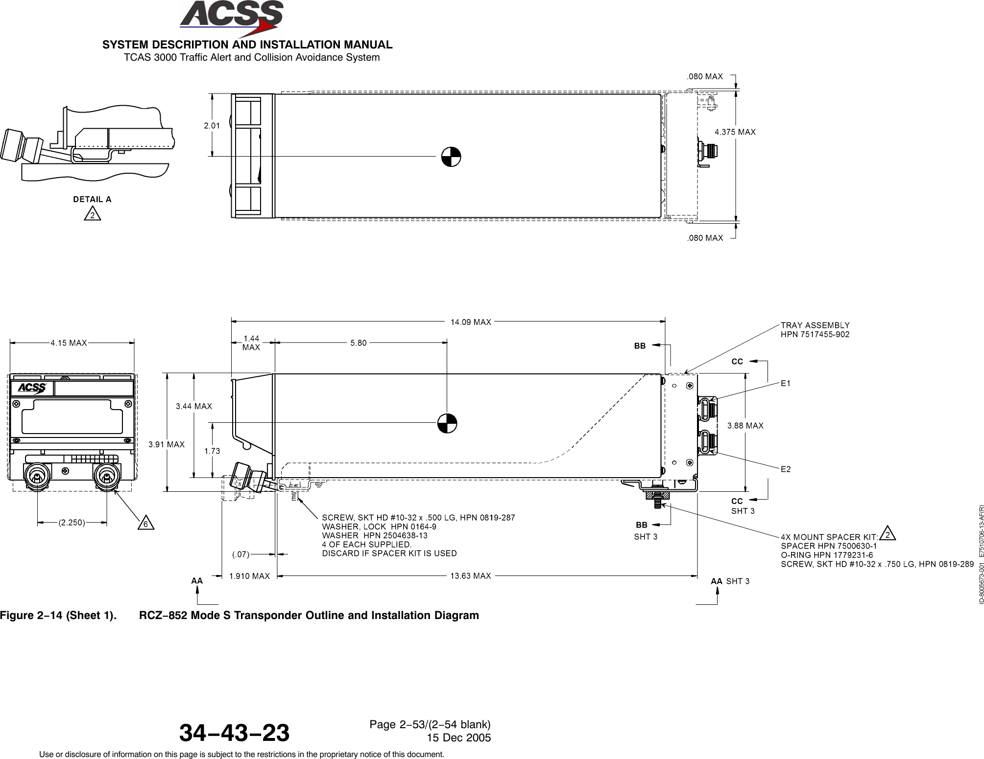
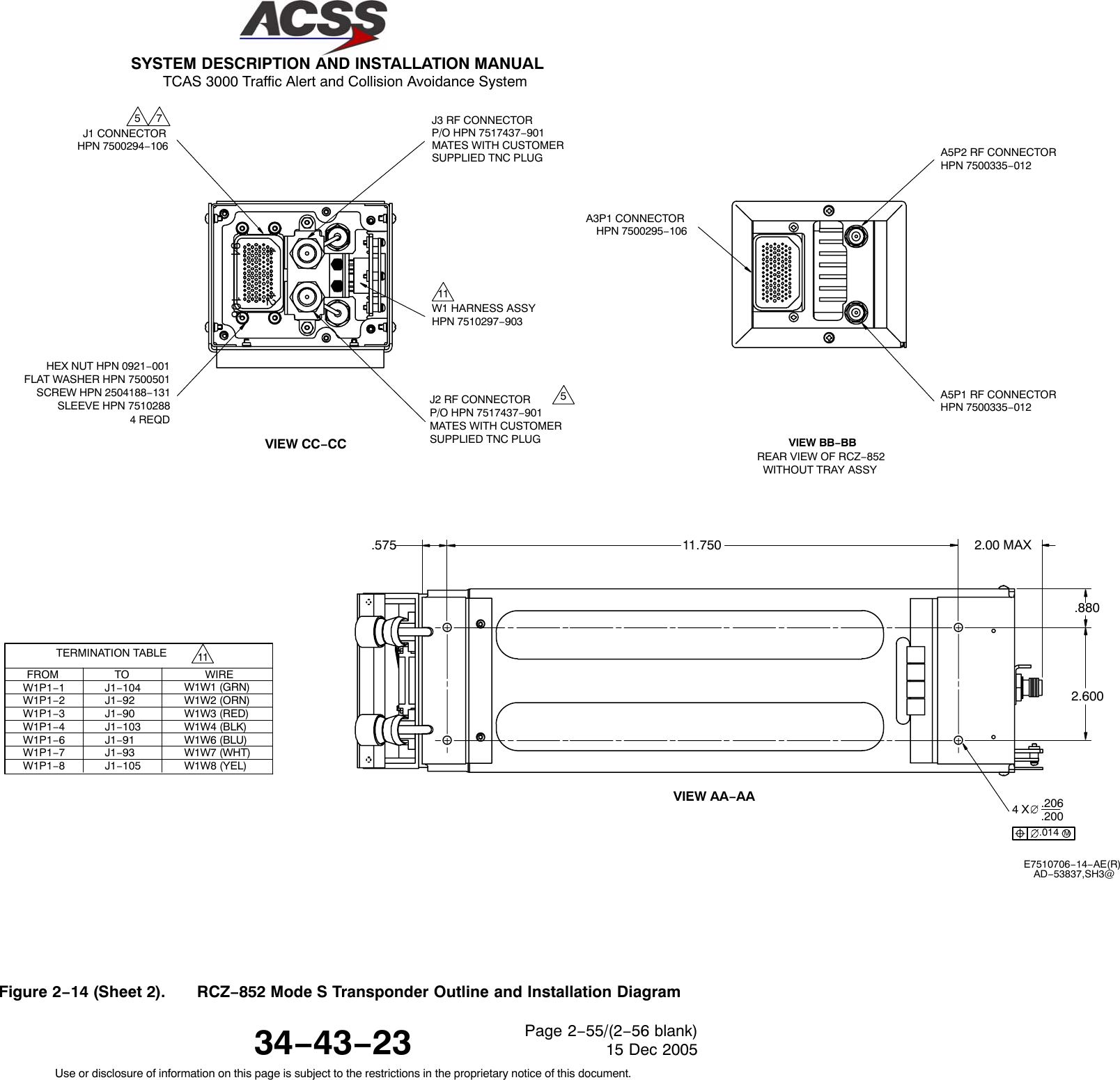
![SYSTEM DESCRIPTION AND INSTALLATION MANUAL TCAS 3000 Traffic Alert and Collision Avoidance System34−43−23Use or disclosure of information on this page is subject to the restrictions in the proprietary notice of this document.Page 1−4815 Dec 2005Table 1−12. RCZ−852 Diversity Mode S Transponder Leading Particulars Item SpecificationDimensions (maximum):•Height . . . . . . . . . . . . . . . . . . . . . . . . . . . . . . . . . . . . . . 3.38 in. (86 mm)•Width . . . . . . . . . . . . . . . . . . . . . . . . . . . . . . . . . . . . . . 4.10 in. (104 mm)•Length . . . . . . . . . . . . . . . . . . . . . . . . . . . . . . . . . . . . . 14.1 in. (358 mm)Weight . . . . . . . . . . . . . . . . . . . . . . . . . . . . . . . . . . . . . . . 5.0 lb (2.27 kg)Power Requirements:•Operating Voltage . . . . . . . . . . . . . . . . . . . . . . . . . . . . +18.0 to +30.3 V dc, +27.5 V dc nominal•Power Consumption:− Standby Mode (No Replies) . . . . . . . . . . . . . . . . . 28 Watts nominal− Active Mode (Maximum Load) . . . . . . . . . . . . . . . 55 Watts maximum•External Circuit Breaker Rating . . . . . . . . . . . . . . . . . 5 A at +27.5 V dcMating Connector . . . . . . . . . . . . . . . . . . . . . . . . . . . . . . ACSS Part No. 7500294−106,Tri−Star Part No. TRAP−106P−26(200);Cannon Part No. DPXAMA−21000−2491(Part of Installation Kit, ACSS Part No.7510707−968)Mounting . . . . . . . . . . . . . . . . . . . . . . . . . . . . . . . . . . . . . . Mount Assembly, ACSS Part No. 7517455−902TSO . . . . . . . . . . . . . . . . . . . . . . . . . . . . . . . . . . . . . . . . . . C112Environmental Specifications . . . . . . . . . . . . . . . . . . . . . DO−160B Environmental Category/A2E1/B/JLMY/E1XXXXXZ/BZ/AZZ•Temperature / Altitude [A2E1]:−Operating Temperature . . . . . . . . . . . . . . . . . . . . . −55 to +70 degrees C−Ground Survival Temperature . . . . . . . . . . . . . . . −55 to +85 degrees C− Altitude . . . . . . . . . . . . . . . . . . . . . . . . . . . . . . . . . . . Sea Level to 70,000 feet−Decompression . . . . . . . . . . . . . . . . . . . . . . . . . . . . 8,000 to 70,000 feet− Overpressure . . . . . . . . . . . . . . . . . . . . . . . . . . . . . −15,000 feet•Vibration [JLMY]:− Category J . . . . . . . . . . . . . . . . . . . . . . . . . . . . . . . Fixed wing turbojet, subsonic and supersonic,fuselage mounting− Category L . . . . . . . . . . . . . . . . . . . . . . . . . . . . . . . Fixed wing reciprocating and turboprop multi andsingle engine over 12,500 pounds, fuselagemounting](https://usermanual.wiki/ACSS-an-L-3-Communications-and-Thales/T3K-4M/User-Guide-718711-Page-75.png)
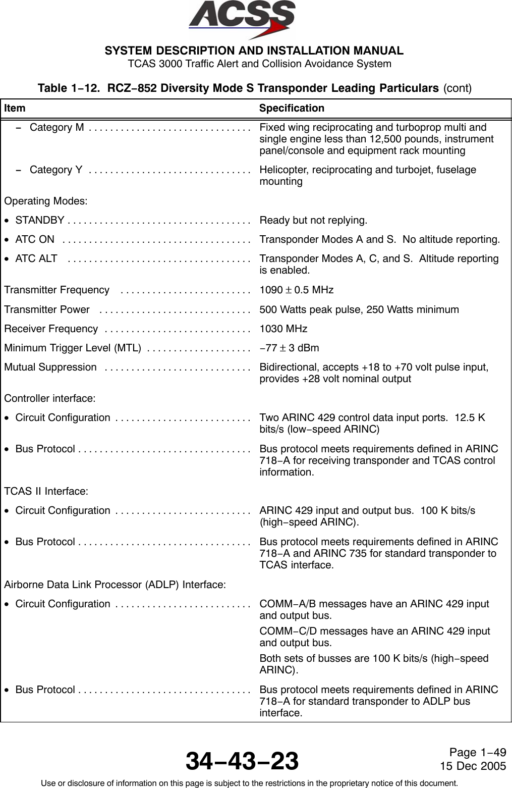


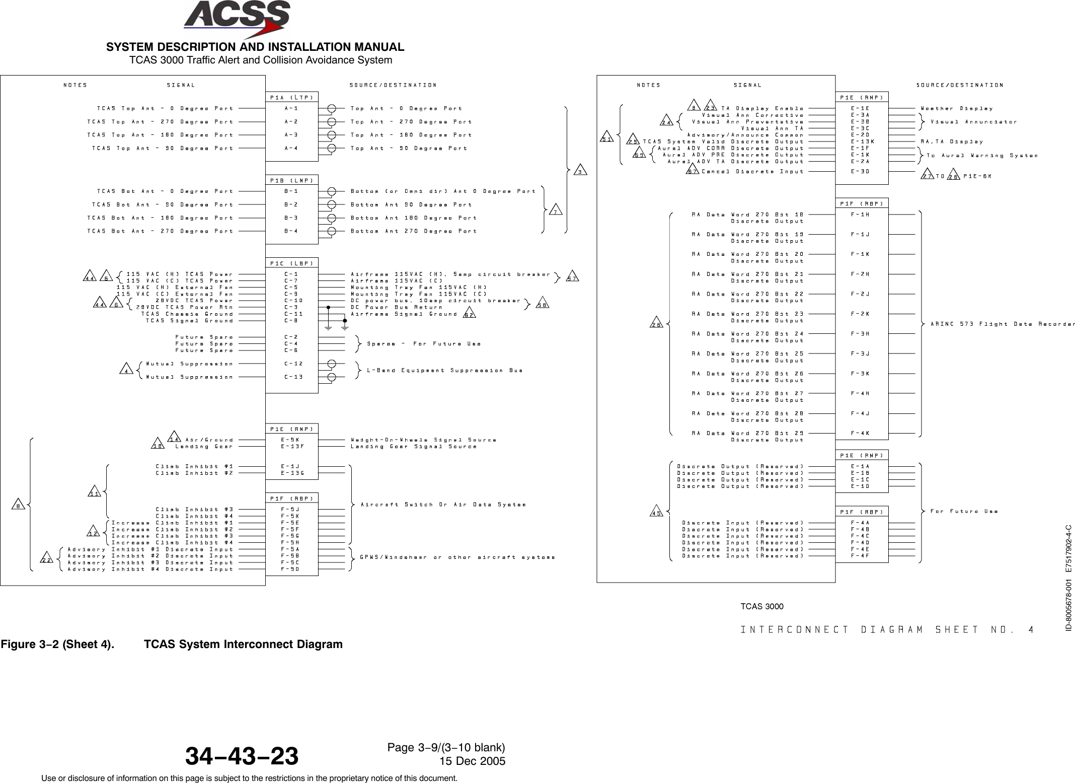
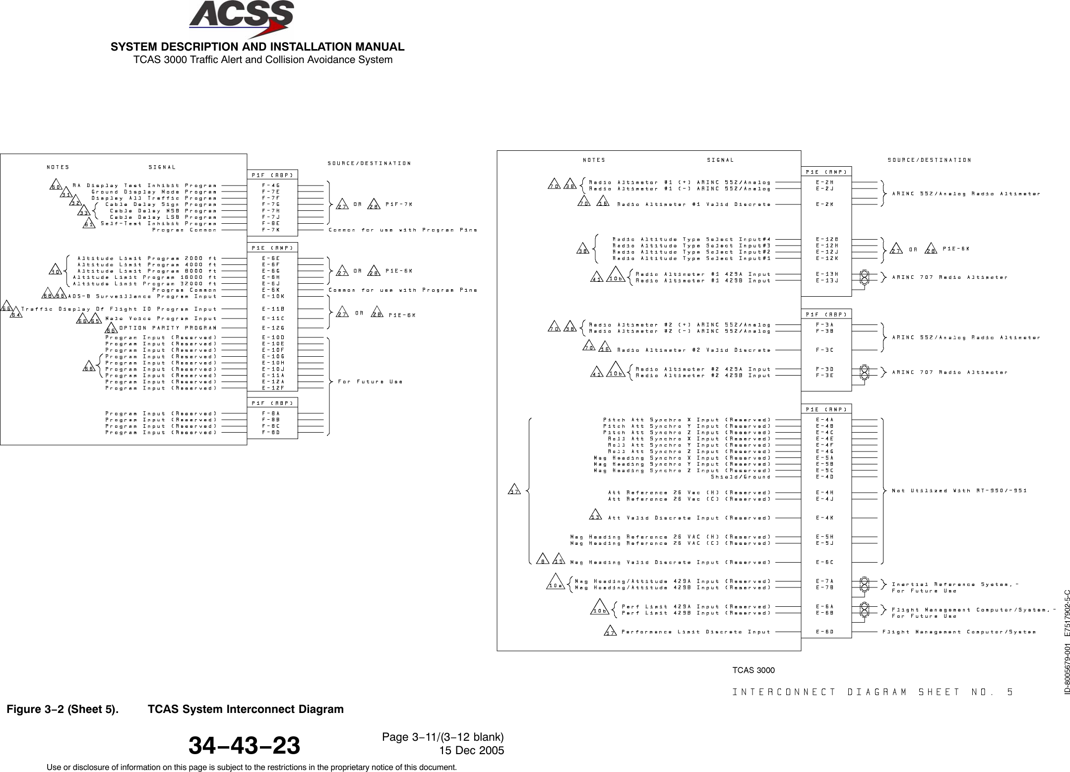
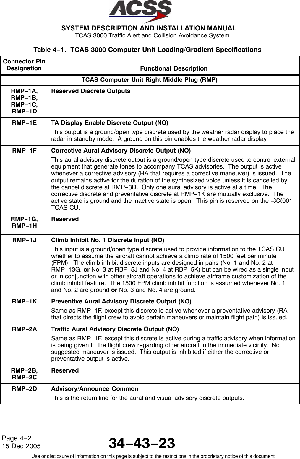
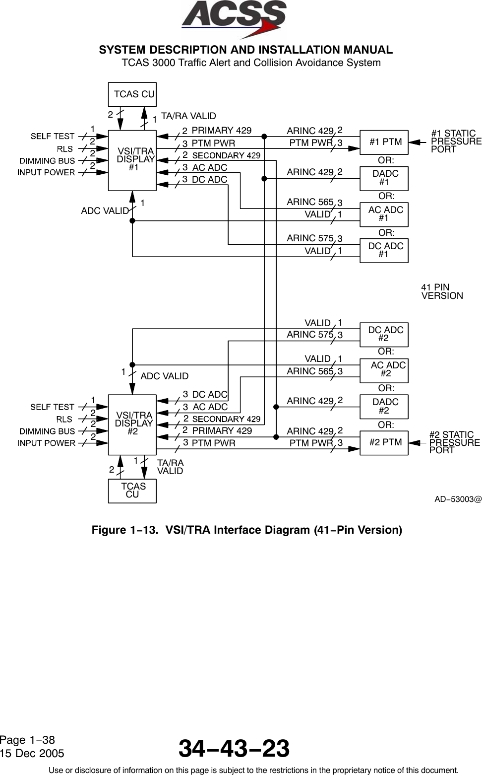
![SYSTEM DESCRIPTION AND INSTALLATION MANUAL TCAS 3000 Traffic Alert and Collision Avoidance System34−43−23Use or disclosure of information on this page is subject to the restrictions in the proprietary notice of this document.Page 4−315 Dec 2005Table 4−1. TCAS 3000 Computer Unit Loading/Gradient Specifications (cont)Connector PinDesignation Functional DescriptionRMP−2E Spare PinRMP−2F, 2G 8−Ohm Audio Output: (RMP−2F [HI], RMP−2G [LO])This is a synthesized voice output supplied by the TCAS computer unit. Its level isprogrammable up to 4 Watts into an 8−ohm speaker. All aural traffic and resolutionadvisories are announced over this output. See RBP−7A for audio level programming.RMP−2H, 2J Radio Altimeter No. 1 ARINC 552/Analog Input: (RMP−2H [HI], RMP−2J [LO])Normal aircraft configurations include either two digital or two analog radio altimetersources. The TCAS computer unit attempts to establish which type is present in order toobtain data from one of the two available sources. TCAS first checks the radio altimeterNo. 1 valid flag at RMP−2K. If No. 1 is not valid then No. 2 valid is checked at RBP−3C.If neither are valid then TCAS checks digital source No. 1 for valid data on the ARINC429 bus at RMP−13H and RMP−13J. If none of the above are valid then the TCASchecks the digital source No. 2 for valid data on the ARINC 429 bus at RBP−3D andRBP−3E. This process is repeated until a valid flag or data is detected.Until a valid source is found, the TCAS computer unit inhibits all surveillance, CAS, andTA/RA display functions, records failures in maintenance memory, and sets the TCASsystem status discrete output at RMP−13K to invalid. The TCAS computer unit usesradio altitude to inhibit advisories and aural annunciation when in close proximity to theground. This analog input No. 1, as well as analog input No. 2, can accept data as a dcvoltage from several types of radio altimeters. The type of radio altimeter is selectedusing the program pins RMP−12B and RMP−12H thru RMP−12K.RMP−2K Radio Altimeter No. 1 Valid Input (PO)See RMP−2H. A valid condition is greater than 18.5 V dc. An invalid is open circuit.RMP−3A Corrective Visual Advisory Discrete Output (NO)The visual advisory discrete outputs are ground/open type discretes used to operate theannunciator lights on the displays. This output is activated whenever a corrective auraladvisory is issued. The output remains active for the duration of the advisory unlesscancelled by the cancel discrete at RMP−3D. Only one visual advisory is active at a time.The active state is ground and the inactive state is open.RMP−3B Preventive Visual Advisory Discrete Output (NO)Same as RMP−3A, except this discrete is activated whenever a preventative auraladvisory is issued.RMP−3C Traffic Visual Advisory Discrete Output (NO)Same as RMP−3A, except this discrete is active during a traffic advisory.RMP−3D Cancel Discrete Input (NO)This input discrete provides a means of canceling aural and visual alerts. It should beconnected to a cancel button (momentary ground type), if used. Groundprox/Windshearhas priority over the cancel button. Open is the inactive state and a momentary ground(less than 50 ohms) produces the active state, canceling any active aural or visual alert.](https://usermanual.wiki/ACSS-an-L-3-Communications-and-Thales/T3K-4M/User-Guide-718711-Page-172.png)
![SYSTEM DESCRIPTION AND INSTALLATION MANUAL TCAS 3000 Traffic Alert and Collision Avoidance System34−43−23Use or disclosure of information on this page is subject to the restrictions in the proprietary notice of this document.Page 4−415 Dec 2005Table 4−1. TCAS 3000 Computer Unit Loading/Gradient Specifications (cont)Connector PinDesignation Functional DescriptionRMP−3E Spare PinRMP−3F, 3G 600−Ohm Audio Output: [RMP−3F (HI), RMP−3G (LO)]This is a synthesized voice output supplied by the TCAS computer unit. Its level isprogrammable up to 80 milliwatts into a 600−ohm audio distribution system. All auraltraffic and resolution advisories are annunciated over this output. See RBP−7A for audiolevel programming.RMP−3H Spare PinsRMP−3J,RMP−3KReserved for future use.RMP−4A Reserved for future use.RMP−4B Reserved for future use.RMP−4C Reserved for future use.RMP−4D Shield GroundReserved for future use.RMP−4E Reserved for future use.RMP−4F Reserved for future use.RMP−4G Reserved for future use.RMP−4H Reserved for future use.RMP−4J Reserved for future use.RMP−4K Attitude Valid Discrete InputReserved for future use.](https://usermanual.wiki/ACSS-an-L-3-Communications-and-Thales/T3K-4M/User-Guide-718711-Page-173.png)
![SYSTEM DESCRIPTION AND INSTALLATION MANUAL TCAS 3000 Traffic Alert and Collision Avoidance System34−43−23Use or disclosure of information on this page is subject to the restrictions in the proprietary notice of this document.Page 4−515 Dec 2005Table 4−1. TCAS 3000 Computer Unit Loading/Gradient Specifications (cont)Connector PinDesignation Functional DescriptionRMP−5A Reserved for future use.RMP−5B Reserved for future use.RMP−5C Reserved for future use.RMP−5D Reserved for future use.RMP−5E ADS−B Program InputIntruder File EnableRMP−5F ADS−B Program InputGP Bus enableRMP−5G ADS−B Program InputFuture SpareRMP−5H Reserved for future use.RMP−5J Reserved for future use.RMP−5K Air Ground Discrete Input (NO): (Weight−On−Wheels)This discrete input to the TCAS computer unit indicates the status of the Air/Ground orWeight−On−Wheels (WOW) switch. TCAS filters this input to make sure it remains in asteady state a minimum of 4 seconds before an Air/Ground transition is recorded. Anopen indicates the aircraft is airborne and a ground indicates the aircraft is on the ground.Inputs should be diode isolated from each other.RMP−6A, 6B ARINC 429 Performance Limit Input: [RMP−6A (A), RMP−6B (B)]This input is provided for future applications to receive climb rate performance limitinformation from an external device such as a Flight Management Computer.RMP−6C Magnetic Heading Valid Discrete InputReserved for future use.RMP−6D Performance Limit Discrete Input (NO)This input provides the TCAS computer unit with an input from the Flight ManagementComputer (or equivalent) which indicates when the aircraft cannot achieve a 1500 FPMclimb rate. When this input is ground, the climb rate is not limited and no action isneeded by the TCAS computer unit. When this input is open, the climb rate is limitedwhen the aircraft is above the value set by the altitude limit program pins (RMP−6E thruRMP−6J).](https://usermanual.wiki/ACSS-an-L-3-Communications-and-Thales/T3K-4M/User-Guide-718711-Page-174.png)
![SYSTEM DESCRIPTION AND INSTALLATION MANUAL TCAS 3000 Traffic Alert and Collision Avoidance System34−43−23Use or disclosure of information on this page is subject to the restrictions in the proprietary notice of this document.Page 4−615 Dec 2005Table 4−1. TCAS 3000 Computer Unit Loading/Gradient Specifications (cont)Connector PinDesignation Functional DescriptionRMP−6E 2000 FT Altitude Limit Program Pin (NO)This pin, along with pins RMP−6F thru RMP−6J, select the “can’t climb” altitude in2,000−foot increments up to 62,000 feet. This is the altitude the aircraft is not able toachieve a 0.25 G vertical acceleration to a 1500 FPM climb rate for an altitude gain of 750feet above a certain altitude under all circumstances. The “can’t climb” altitude isselected by connecting jumper wires from altitude limit program pins to the programcommon pin (RMP−6K).RMP−6F 4000 FT Altitude Limit Program Pin (NO)See RMP−6E.RMP−6G 8000 FT Altitude Limit Program Pin (NO)See RMP−6E.RMP−6H 16000 FT Altitude Limit Program Pin (NO)See RMP−6E.RMP−6J 32000 FT Altitude Limit Program Pin (NO)See RMP−6E.RMP−6K Program CommonSee RMP−6E.RMP−7A, 7B ARINC 429 Magnetic Heading/Attitude Input: [RMP−7A (A), RMP−7B (B)]Reserved for future useRMP−7C, 7D ARINC 429 TA/RA Display No. 1 Output: [RMP−7C (A), RMP−7D (B)]This is one of two ARINC 429 high speed bus outputs that supplies data to the TA/RAdisplay such as a VSI/TRA or EFIS. The other output (TA/RA Display No. 2) is atRMP−7G and −7H. The TA/RA Display No. 1 outputs are also connected to the front(PDL) connector, which is used to supply display information to maintenance displays.See J1−33 and J1−34.RMP−7E TA/RA Display No. 1 Status Discrete Input (NO)Two display status discrete inputs are provided by the TCAS computer unit at RMP−7E(TA/RA Display No. 1) and RMP−7J (TA/RA Display No. 2). A ground on either of theseinputs is interpreted by TCAS to mean the display associated with that input is operatingnormally and is capable of displaying the TA/RA information, and that its data bus isactive. An open indicates the inability of the display to present advisories or indicates itsdata bus is inactive.RMP−7F Spare PinRMP−7G, 7H ARINC 429 TA/RA Display No. 2 Output: [RMP−7G (A), RMP−7H (B)]See RMP−7C and −7D.RMP−7J TA/RA Display No. 2 Status Discrete Input (NO)See RMP−7E.RMP−7K Spare Pin](https://usermanual.wiki/ACSS-an-L-3-Communications-and-Thales/T3K-4M/User-Guide-718711-Page-175.png)
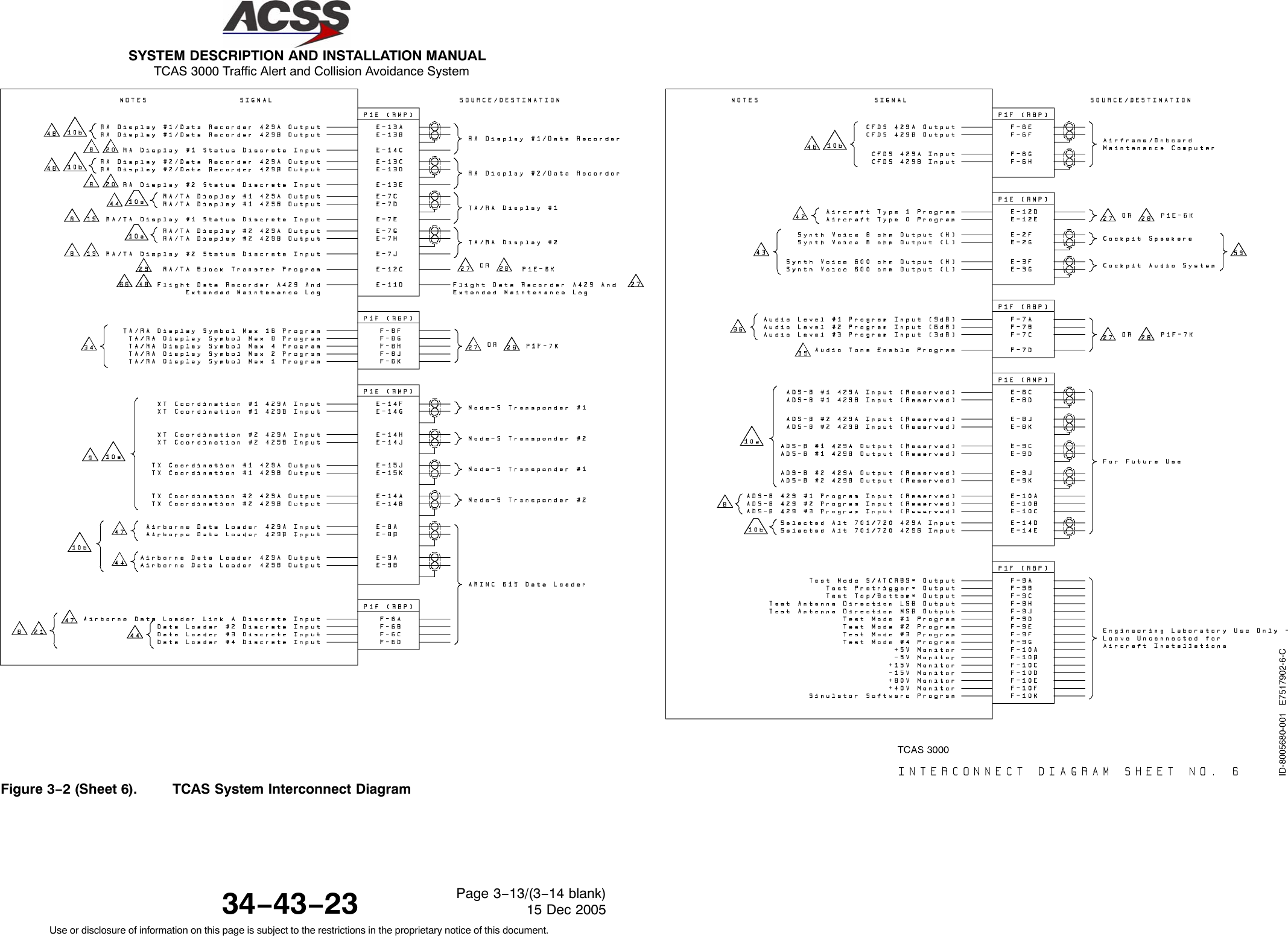
![SYSTEM DESCRIPTION AND INSTALLATION MANUAL TCAS 3000 Traffic Alert and Collision Avoidance System34−43−23Use or disclosure of information on this page is subject to the restrictions in the proprietary notice of this document.Page 4−715 Dec 2005Table 4−1. TCAS 3000 Computer Unit Loading/Gradient Specifications (cont)Connector PinDesignation Functional DescriptionRMP−8A, 8B ARINC 429 Data Loader Input: [RMP−8A (A), RMP−8B (B)]These pins are used when the TCAS computer unit is communicating with an ARINC 603or 615 airborne data loader (ADL) through the rear ARINC 600 connector. The dataloader programs the program memory in the TCAS computer unit per the data loaderfunction specified. The ADL and portable data loader (PDL) ARINC 429 inputs haveseparate receiver busses to allow for simultaneous connection of the ADL and PDL.These pins are also connected to the front (PDL) connector on the front of the unit. SeeJ1−1 and J1−2.RMP−8C,8D TA/RA Display Control ARINC 429 Input #1: [RMP−8C (A), RMP−8D (B)]RMP−8E, 8F ARINC 429 Bus Input: [RMP−8E (A), RMP−8F (B)]Reserved for future use.RMP−8G, 8H TA/RA Display Control ARINC 429 Input #2: [RMP−8G (A), RMP−8H (B)]RMP−8J, 8K ARINC 429 ADS−B No. 2 Input: [RMP−8J (A), RMP−8K (B)]Reserved for future use.RMP−9A, 9B ARINC 429 Data Loader Output: [RMP−9A (A), RMP−9B (B)]These pins are used when the TCAS computer unit is communicating with an ARINC 603or 615 airborne data loader (ADL) through the rear ARINC 600 connector. Thisconnection is used to transmit data to the ADL during data loading operations.These pins are also connected to the front (PDL) connector on the front of the unit. SeeJ1−8 and J1−9.RMP−9C, 9D ARINC 429 ADS−B No. 1 Output: [RMP−9C (A), RMP−9D (B)]Reserved for future use.RMP−9E, 9F ARINC 429 Bus Output: [RMP−9E (A), RMP−9F (B)]Reserved for future use.RMP−9G, 9H ARINC 429 Bus Output: [RMP−9G (A), RMP−9H (B)]Reserved for future use.RMP−9J, 9K ARINC 429 ADS−B No. 2 Output: [RMP−9J (A), RMP−9K (B)]Reserved for future use.](https://usermanual.wiki/ACSS-an-L-3-Communications-and-Thales/T3K-4M/User-Guide-718711-Page-176.png)
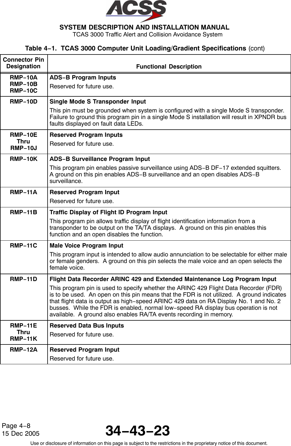
![SYSTEM DESCRIPTION AND INSTALLATION MANUAL TCAS 3000 Traffic Alert and Collision Avoidance System34−43−23Use or disclosure of information on this page is subject to the restrictions in the proprietary notice of this document.Page 4−1015 Dec 2005Table 4−1. TCAS 3000 Computer Unit Loading/Gradient Specifications (cont)Connector PinDesignation Functional DescriptionRMP−12C RA/TA Block Transfer Program Input (NO)This program input determines the type of block transfer that is made from the TCAScomputer unit to the TA/RA displays. If this pin is grounded, the TCAS computer unittransmits in ACSS BCA EFIS format. If the TCAS computer unit senses an open at thispin, it transmits in ARINC 735 format.RMP−12D Reserved Program InputRMP−12E Reserved Program InputRMP−12F Spare PinRMP−12G Option Parity Program InputThe TCAS computer unit uses nine discrete program input pins to determine whichoptions have been selected by the installer. Eight of these pins are used to determineoption selections. The ninth pin (RMP−12G) is used to determine parity for the eightoption selection pins (RMP−10G, −10H, −10J, −10K, −11A, −11B, −11C, and −11D). Todetermine parity, count the number of option pins that are grounded. If the number ofpins that are grounded is an odd number (1, 3, 5, 7), ground pin RMP−12G. If thenumber of grounded pins in the option group is an even number (0, 2, 4, 6, 8), leave pinRMP−12G open.RMP−12H Analog Radio Altimeter Type Select Program Input No. 3 (NO)See RMP−12B.RMP−12J Analog Radio Altimeter Type Select Program Input No. 2 (NO)See RMP−12B.RMP−12K Analog Radio Altimeter Type Select Program Input No. 1 (NO)See RMP−12B.RMP−13A, 13B RA Display No. 1/ARINC 429 Data Recorder Output: [RMP−13A (A), RMP−13B (B)]These ARINC 429 outputs are configured to output either RA information or for use as anARINC 429 data recorder function. The output is configured by program pin RMP−11D.When RMP−11D is open (standard configuration), the bus is configured for low−speedARINC 429 operation and RA information is output according to the format specified forthe RA display bus in ARINC 735. When RMP−11D is grounded, the bus is configured forhigh−speed ARINC 429 operation and the output supplies TA and RA information to a 429data recorder.RMP−13C, 13D RA Display No. 2/ARINC 429 Data Recorder Output: [RMP−13C (A), RMP−13D (B)]See RMP−13A.RMP−13E RA Display No. 2 Status Discrete Input (NO)This input provides the functional status of RA Display No. 2. A ground on this pinindicates a valid display. If this discrete is not used by the RA Display, connect to aircraftground to prevent RA DISPLAY No. 2 fail message during self−test.](https://usermanual.wiki/ACSS-an-L-3-Communications-and-Thales/T3K-4M/User-Guide-718711-Page-179.png)
![SYSTEM DESCRIPTION AND INSTALLATION MANUAL TCAS 3000 Traffic Alert and Collision Avoidance System34−43−23Use or disclosure of information on this page is subject to the restrictions in the proprietary notice of this document.Page 4−1115 Dec 2005Table 4−1. TCAS 3000 Computer Unit Loading/Gradient Specifications (cont)Connector PinDesignation Functional DescriptionRMP−13F Landing Gear Discrete Input (NO)The TCAS computer unit monitors this discrete that indicates the landing gear position.An open indicates the gear is retracted (gear is up) and a ground indicates the gear isextended (gear is down).RMP−13G Climb Inhibit No. 2 Discrete Input (NO)See RMP−1J.RMP−13H, 13J Radio Altimeter No. 1 Input: [RMP−13H (A), RMP−13J (B)]This input is provided for ARINC 429 altitude inputs from an ARINC 707 digital radioaltimeter. Radio altitude data is used for computation of sensitivity level, inhibit descendadvisories, and inhibit aural annunciation when in close proximity to the ground. Also seeRMP−2H.RMP−13K TCAS System Valid Discrete Output (NO)This discrete output indicates the health status of the TCAS computer unit to otheravionics systems that monitor TCAS system status. This output is used in retrofitinstallations where instrumentation needs to monitor TCAS status. A ground at this pinindicates normal TCAS operation. An open indicates a TCAS fault.RMP−14A, 14B ARINC 429 TX Coordination Bus No. 2 Output: [RMP−14A (A), RMP−14B (B)]This differential pair output is a high speed ARINC 429 bus (100K bits/second nominal),that transmits data from the TCAS computer unit to the No. 2 Mode S Transponder.The labels on this bus are as follows: 273, 274, 275.RMP−14C RA Display No. 1 Status Discrete Input (NO)This input provides the functional status of RA Display No. 1. A ground on this pinindicates a valid display. If this discrete is not used by the RA display, connect to aircraftground to prevent RA DISPLAY No. 1 fail message during self−test.RMP−14D, 14E Selected Altitude701/720 ARINC 429 Bus InputReserved for future use.RMP−14F, 14G ARINC 429 XT Coordination No. 1 Input: [RMP−14F (A), RMP−14G (B)]This differential pair input is a high speed ARINC 429 bus (100K bits/second nominal),that receives data from the No. 1 Mode S Transponder.The labels on this bus are as follows: 013, 015, 016, 203, 271, 272, 273, 274, 275, 276,277, 350.RMP−14H, 14J ARINC 429 XT Coordination No. 2 Input: [RMP−14H (A), RMP−14J (B)]This differential pair input is a high speed ARINC 429 bus (100K bits/second nominal),that receives data from the No. 2 Mode S Transponder.The labels on this bus are as follows: 013, 015, 016, 203, 271, 272, 273, 274, 275, 276,277, 350.RMP−14K Spare Pin](https://usermanual.wiki/ACSS-an-L-3-Communications-and-Thales/T3K-4M/User-Guide-718711-Page-180.png)
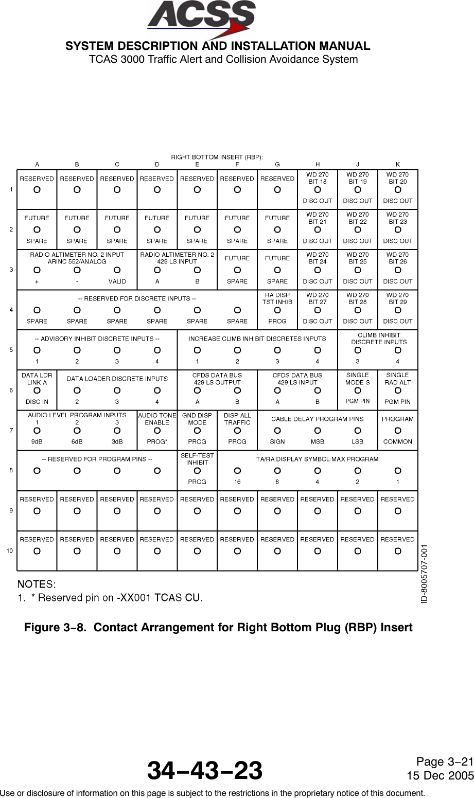
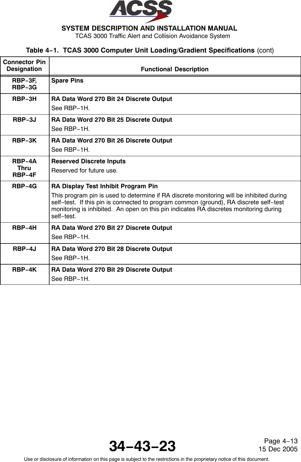
![SYSTEM DESCRIPTION AND INSTALLATION MANUAL TCAS 3000 Traffic Alert and Collision Avoidance System34−43−23Use or disclosure of information on this page is subject to the restrictions in the proprietary notice of this document.Page 4−1215 Dec 2005Table 4−1. TCAS 3000 Computer Unit Loading/Gradient Specifications (cont)Connector PinDesignation Functional DescriptionRMP−15AthruRMP−HReserved for future use.RMP−15J, 15K ARINC 429 TX Coordination No. 1 Output: [RMP−15J (A), RMP−15K (B)]This differential pair output is a high speed ARINC 429 bus (100K bits/second nominal),that transmits data from the TCAS computer unit to the No. 1 Mode S Transponder.The labels on this bus are as follows: 273, 274, 275.TCAS Computer Unit Right Bottom Plug (RBP)RBP−1AThruRBP−1GReserved for future use.RBP−1H RA Data Word 270 Bit 18 Discrete OutputThis discrete output provides RA information to the ARINC 573 flight recorder. Theoutput goes to the “ground” state each time its associated bit within the advisory field ofthe RA output words changes from a “zero” condition to a “one” condition. The outputremains in the “ground” state for as long as the associated RA bit remains non−zero.This output is read by the flight recorder as either a series or shunt output.RBP−1J RA Data Word 270 Bit 19 Discrete OutputSee RBP−1H.RBP−1K RA Data Word 270 Bit 20 Discrete OutputSee RBP−1H.RBP−2AThruRBP−2GSpare PinsRBP−2H RA Data Word 270 Bit 21 Discrete OutputSee RBP−1H.RBP−2J RA Data Word 270 Bit 22 Discrete OutputSee RBP−1H.RBP−2K RA Data Word 270 Bit 23 Discrete OutputSee RBP−1H.RBP−3A, 3B Radio Altimeter No. 2 ARINC 552/Analog Input: [RBP−3A (HI), RBP−3B (LO)]See RMP−2H and −2J.RBP−3C Radio Altimeter No. 2 Valid Discrete Input (PO)See RMP−2H. Valid condition is greater than 18.5 V dc. Invalid is open.RBP−3D, 3E Radio Altimeter No. 2 Input: [RBP−3D (A), RBP−3E (B)]See RMP−13H. Also see RMP−2H.](https://usermanual.wiki/ACSS-an-L-3-Communications-and-Thales/T3K-4M/User-Guide-718711-Page-181.png)
![SYSTEM DESCRIPTION AND INSTALLATION MANUAL TCAS 3000 Traffic Alert and Collision Avoidance System34−43−23Use or disclosure of information on this page is subject to the restrictions in the proprietary notice of this document.Page 4−1515 Dec 2005Table 4−1. TCAS 3000 Computer Unit Loading/Gradient Specifications (cont)Connector PinDesignation Functional DescriptionRBP−5K Climb Inhibit Discrete Input No. 4 (NO)See RMP−1J.RBP−6A Airborne Data Loader Link A Discrete InputThis discrete input, along with Data Loader Discrete Inputs No. 2, 3, and 4 (pins RBP−6B,RBP−6C, and RBP−6D, respectively), is a ground/open type discrete that specifies whattype of data loader (ARINC 603 or ARINC 615) is attached. The TCAS computer unit hasseparate receiver busses and separate data loader enable discrete inputs to supportsimultaneous connections to an ADL and PDL. A ground on pin RBP−6A indicates thatan airborne data loader is connected to the rear connector of the TCAS computer unit. Aground on pin J1−18, PDL Link A Discrete Input, indicates that a portable data loader isconnected to the front connector of the TCAS computer unit. The data loader discreteinputs at RBP−6B, RBP−6C, and RBP−6D are also connected to the data loader discreteinputs on the front connector (pins J1−51, J1−52, and J1−53, respectively). Listed belowis an active discrete (selected) indicated by a ground and an inactive discrete (notselected) indicated by an open. J1−51/ J1−52/ J1−53/RBP−6A J1−18 RBP−6B RBP−6C RBP−6D FunctionGround Open Ground Open Open ARINC 615 ADLGround Open Open Ground Open ARINC 603 ADLOpen Ground Ground Open Open ARINC 615 PDLOpen Ground Open Ground Open ARINC 603 PDL − − − − − − − −Ground SW Part Number is outputRBP−6B Data Loader Discrete Input No. 2See RBP−6A.RBP−6C Data Loader Discrete Input No. 3See RBP−6A.RBP−6D Data Loader Discrete Input No. 4See RBP−6A.RBP−6E, 6F ARINC 429 CFDS Output: [RBP−6E (A), RBP−6F (B)]This differential pair output is a low speed ARINC 429 bus (12.5K bits/second nominal),that transmits data to an onboard maintenance computer or a central fault display system.RBP−6G, 6H ARINC 429 CFDS Input: [RBP−6G (A), RBP−6H (B)]This differential pair input is a low speed ARINC 429 bus (12.5K bits/second nominal),that receives data from an onboard maintenance computer or a central fault displaysystem.RBP−6J Single Mode S Program PinGround this pin when the computer is connected to a single mode S transponder.RBP−6K Single Radio Altimeter Program PinGround this pin when the computer is connected to a single radio altimeter.](https://usermanual.wiki/ACSS-an-L-3-Communications-and-Thales/T3K-4M/User-Guide-718711-Page-184.png)
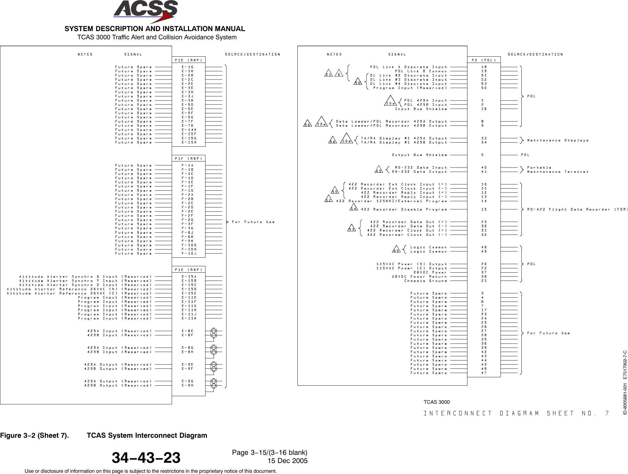
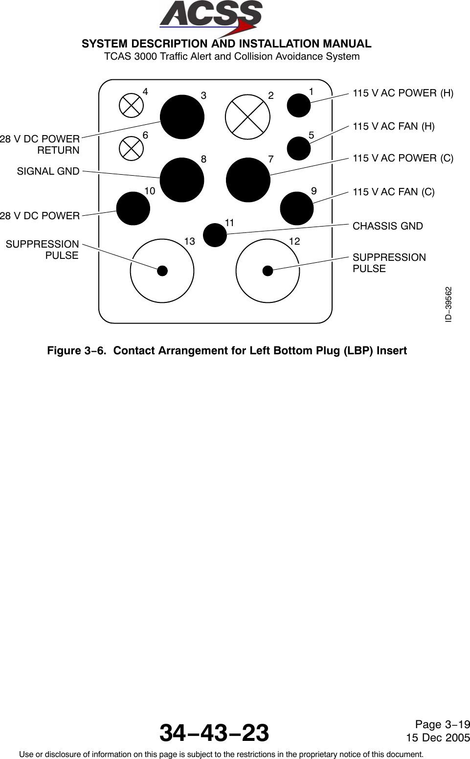
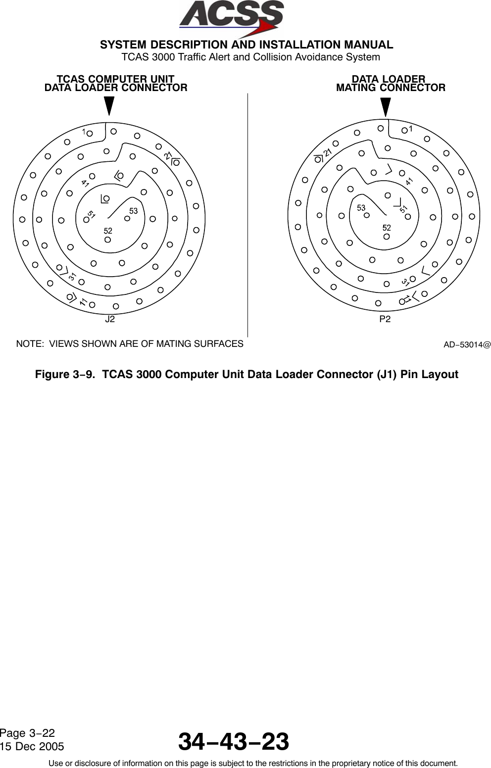
![SYSTEM DESCRIPTION AND INSTALLATION MANUAL TCAS 3000 Traffic Alert and Collision Avoidance System34−43−23Use or disclosure of information on this page is subject to the restrictions in the proprietary notice of this document.Page 4−2015 Dec 2005Table 4−1. TCAS 3000 Computer Unit Loading/Gradient Specifications (cont)Connector PinDesignation Functional DescriptionLBP−10 +28 V dc Power Input (HI)This pin along with the TCAS computer unit 28 V dc Power Return line (LBP−3) providethe +28 V dc power requirements for the TCAS computer unit.NOTE: This TCAS computer unit operates with either 115 V ac, 400 Hz, or 28 V dcinput power. If +28 V dc is used, the power should be connected through a 10Amp circuit breaker, and the pins for the 115 V ac input should be leftunconnected.LBP−11 Chassis GroundConnect to aircraft frame.LBP−12 Mutual Suppression Pulse Bus InputThe TCAS computer unit joins the mutual suppression bus daisy chained through TCASand other RF transmitting equipment on board the aircraft. TCAS receives suppressionpulses from other LRUs on this bus, which is used to suppress the TCAS receivers duringsuch transmissions. This prevents the TCAS computer unit from interpreting thesetransmissions as valid replies from an intruder aircraft. When not suppressed, the TCAScomputer unit transmits its own suppression pulses on the same bus in order to suppressthe receivers in other L−band systems on the aircraft. This pin is designated as the input.Pin LBP−13 is directly connected to this pin internally and functions as the output.L−Band suppression coax must be RG−142, RG400, or equivalent coaxial cable whichmeets the operational characteristics required by ARINC 735. LBP−12 and LBP−13 areconnected internally. Connection to only one pin is required.LBP−13 Mutual Suppression Pulse Bus OutputSee LBP−12.The Interface descriptions that follow are for the 53−pin Data Loader connector J1 mounted on thefront panel of the TCAS computer unit. These descriptions are used to make up the cable that isused to interface between the TCAS computer unit and an ARINC 615 Portable Data Loader (PDL), aRS−232 PC Serial Port, a RS−422 Flight Data Recorder, or an ARINC 429 Maintenance Display.J1−1, 2 ARINC 429 PDL Bus Input: [J1−1 (A), J1−2 (B)]This differential pair input is a high−speed ARINC 429 bus (100K bits/second nominal)that is used to input data from the data loader to the TCAS computer unit. The standardsfor this interface are defined in ARINC 615 Airborne Computer High Speed Data Loader.These pins should be connected to pins 1 and 2 of the PDL cable interface.J1−3,J1−4Spare PinsJ1−5Output Bus ShieldsThe shields from the output bus (J1−8, 9) should be connected to this pin.J1−6,J1−7ARINC 615 Data Loader Ethernet: [J1−6 TD+,J1−7 TD−]](https://usermanual.wiki/ACSS-an-L-3-Communications-and-Thales/T3K-4M/User-Guide-718711-Page-189.png)
![SYSTEM DESCRIPTION AND INSTALLATION MANUAL TCAS 3000 Traffic Alert and Collision Avoidance System34−43−23Use or disclosure of information on this page is subject to the restrictions in the proprietary notice of this document.Page 4−2115 Dec 2005Table 4−1. TCAS 3000 Computer Unit Loading/Gradient Specifications (cont)Connector PinDesignation Functional DescriptionJ1−8, 9 ARINC 429 Data Loader/PDL Recorder Bus Output: [J1−8 (A), J1−9 (B)]This differential pair output is a high−speed ARINC 429 bus (100K bits/second nominal)that is used to output data from the TCAS computer unit to the data loader. Thestandards for this interface are defined in ARINC 615 Airborne Computer High SpeedData Loader.These pins should be connected to pins 8 and 9 of the PDL cable interface.J1−10thruJ1−15ARINC 615 Data LoaderReservedJ1−16 Input Bus ShieldsThe shields from the input bus (J1−1, 2) should be connected to this pin.J1−17 Spare PinJ1−18 PDL Link A Discrete InputThis is a ground/open discrete from an portable ARINC 615 or ARINC 603 data loaderwhich indicates, to the TCAS computer unit, that a data loader is connected. A groundindicates a data loader is connected.J1−19 PDL Link B CommonConnect this pin to pin 19 of the PDL cable interface.J1−20, 22 115 V ac Power Output: [J1−20 (H), J1−22 (C)]These power output pins provide the 115 V ac operating power for the data loader.The 115 V ac (H) and 115 V ac (C) interconnect wires should be shielded or twisted andshielded with an insulating jacket over the shield. The shield should be connected tochassis ground (J1−21).J1−21 Chassis GroundConnect 115 V ac power shields to this pin.J1−23 ARINC 615 Data Loader Ethernet Input (RD+)J1−24thruJ1−32ReservedJ1−33,34 ARINC 429 TA/RA Display No. 1 Output: [J1−33 (A), J1−34 (B)]This bus can be used to connect to a maintenance display. These pins are alsoconnected to the ARINC 600 connector on the rear of the unit (RMP−7C and −7D).J1−35,J1−36Reserved](https://usermanual.wiki/ACSS-an-L-3-Communications-and-Thales/T3K-4M/User-Guide-718711-Page-190.png)
![SYSTEM DESCRIPTION AND INSTALLATION MANUAL TCAS 3000 Traffic Alert and Collision Avoidance System34−43−23Use or disclosure of information on this page is subject to the restrictions in the proprietary notice of this document.Page 4−2215 Dec 2005Table 4−1. TCAS 3000 Computer Unit Loading/Gradient Specifications (cont)Connector PinDesignation Functional DescriptionJ1−37, 38 28 V dc Power Output: [J1−37 (HI), J1−38 (LO)]These power output pins provide the 28 V dc operating power for the data loader. Thesepins are used only if the data loader operates from a +28 V dc source.J1−39 ReservedJ1−40 RS−232 Data InputThis pin is used to receive RS−232 data from a portable maintenance terminal.J1−41 RS−232 Data OutputThis pin is used to transmit RS−232 data to a portable maintenance terminal.J1−42ThruJ1−47Spare PinsJ1−48,J1−49Logic CommonCommon lines for the RS−232 Data Input/Output lines. These two pins are tied togetherin the TCAS computer unit.J1−50 Reserved PinJ1−51 Data Loader Link No. 2 Discrete InputPins J1−51 and J1−52 are ground/open discretes from a portable data loader, which areused to specify what type of data loader (ARINC 603 or ARINC 615) is connected to theTCAS computer unit. These two pins are also connected to the ARINC 600 connector onthe rear of the unit (RBP−6B and −6C respectively).J1−52 Data Loader Link No. 3 Discrete InputSee J1−51.J1−53 Data Loader Link No. 4 Discrete InputThis is a ground/open discrete from a Portable Data Loader (PDL) that is used to transmitthe software part number on the Data Loader output bus when grounded, The landinggear indicates extended, and the air/ground indicates ground. This pin is also connectedto the ARINC 600 connector on the rear of the unit (RBP−6D).](https://usermanual.wiki/ACSS-an-L-3-Communications-and-Thales/T3K-4M/User-Guide-718711-Page-191.png)
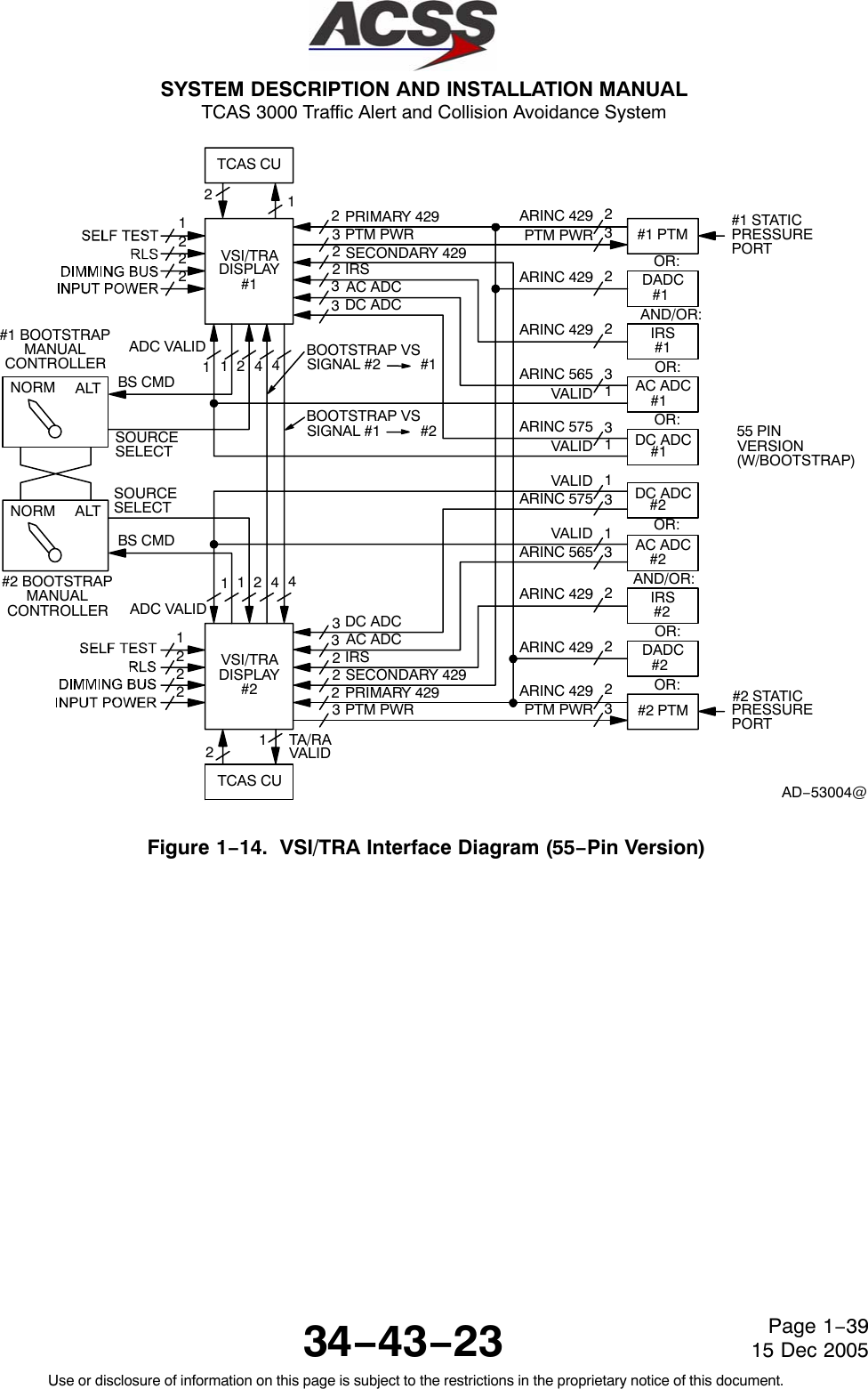
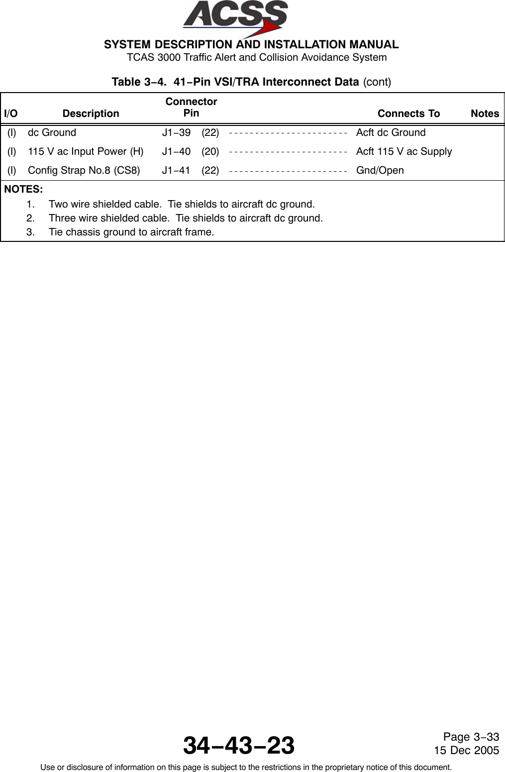
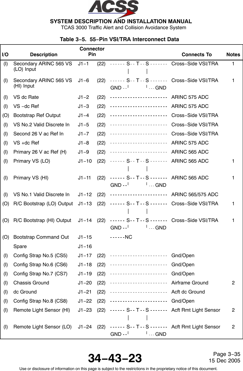
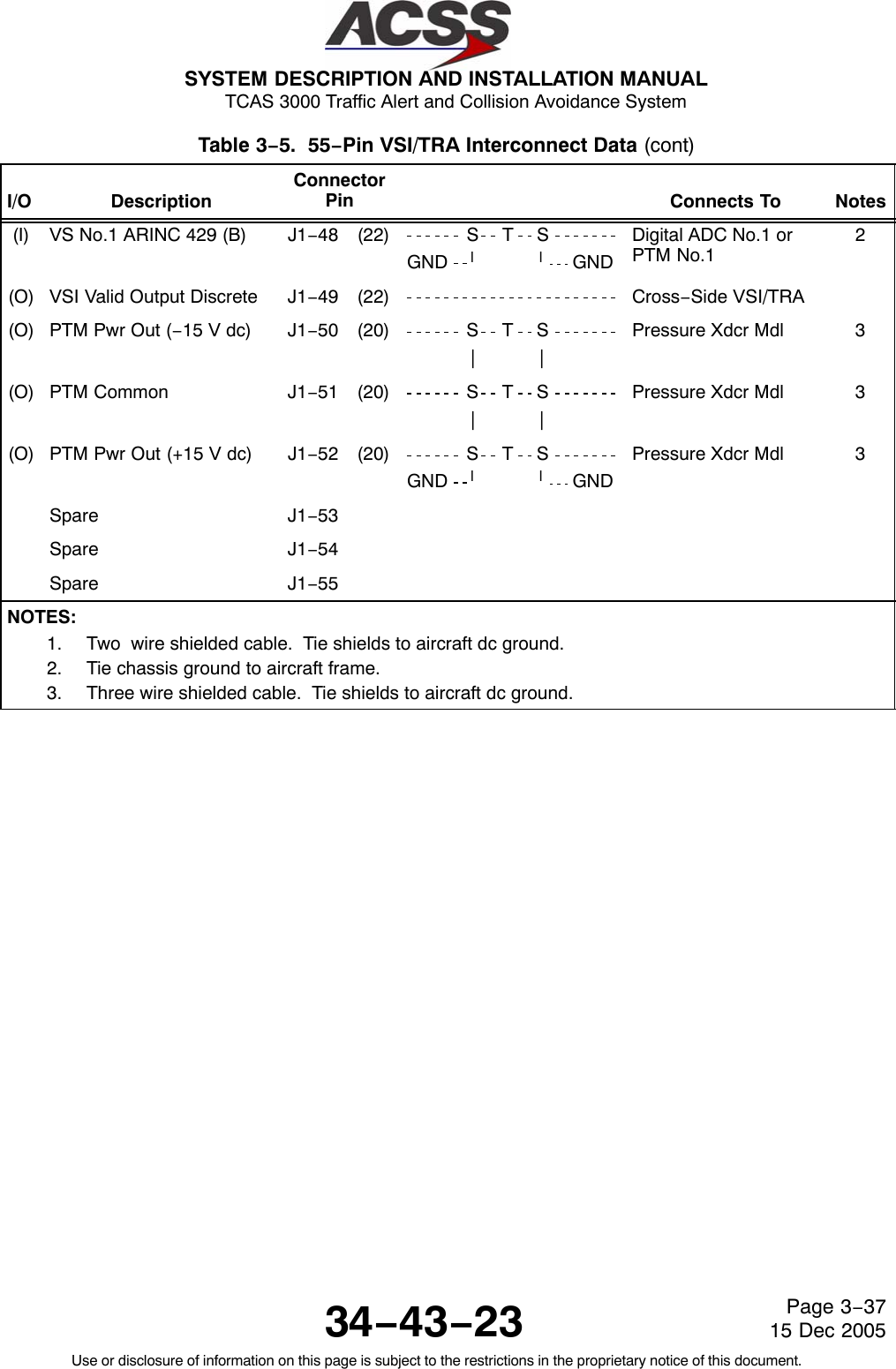
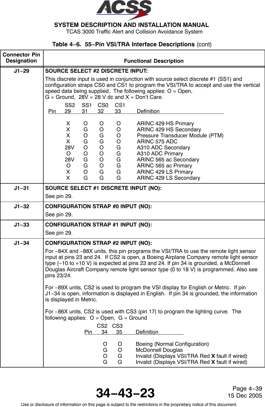
![SYSTEM DESCRIPTION AND INSTALLATION MANUAL TCAS 3000 Traffic Alert and Collision Avoidance System34−43−23Use or disclosure of information on this page is subject to the restrictions in the proprietary notice of this document.Page 4−3615 Dec 2005Table 4−6. 55−Pin VSI/TRA Interface Descriptions Connector PinDesignation Functional DescriptionJ1−1, 6 SECONDARY ARINC 565 VERTICAL SPEED BUS INPUT: [J1−6 (HI), J1−1 (LO)]This two wire bus input receives ARINC 565 vertical speed data from the cross−sidedisplay when the bootstrap mode is activated. This bus input is connected to the R/CBootstrap Output bus on the cross−side display as follows:J1−6 of the on−side display is connected to J1−14 of the cross−side display.J1−1 of the on−side display is connected to J1−13 of the cross−side display.J1−2VERTICAL SPEED DC RATE INPUT:Pins 2, 3 and 8 are inputs to the VSI/TRA from an ARINC 575 air data computerindicating vertical speed. Pin 2 receives a +10 to −10 V dc rate signal from the ADC. Pin3 is a −12 V dc regulated reference voltage from the ADC and pin 8 is a +12 V dcregulated reference voltage from the ADC. Also see pins 29, 31, 32, and 33.J1−3VERTICAL SPEED −DC REFERENCE INPUT:See pin 2.J1−4BOOTSTRAP REFERENCE OUTPUT:This output sends the bootstrap ARINC 565 ac reference voltage to the cross−sidedisplay. The output is connected to the Secondary 26 V ac Reference Input (pin 7) of thecross−side display.J1−5VERTICAL SPEED NO. 2 VALID DISCRETE INPUT:This discrete input receives bootstrap ARINC 565 vertical speed valid data from thecross−side display. The input is connected to the Vertical Speed Output (pin 49) of the cross−side display.J1−7SECONDARY 26 V ac REFERENCE INPUT:This input receives the bootstrap ARINC 565 ac reference voltage from the cross−sidedisplay. The input is connected to the Bootstrap Reference Output (pin 40) of thecross−side display.J1−8VERTICAL SPEED +DC REFERENCE INPUT:See pin 2.J1−9PRIMARY VERTICAL SPEED 26 V ac, 400 HZ REFERENCE INPUT:See pins 10, 11.J1−10, 11 PRIMARY VERTICAL SPEED ARINC 565 AC INPUT: (J1−11 HIGH, J1−10 LOW)Pins 9, 10, 11, and 12 are inputs to the VSI/TRA from an ARINC 565 air data computer orIRS. A 26 V ac, 400 Hz reference signal is received on pin 9 (HI). Pin 11 (HI) and pin 10(LO) provide an amplitude modulated 400 Hz signal with a maximum voltage of " 6.25volts. The RMS value of this signal is used by the VSI/TRA to compute and display thevertical rate. The phase of this signal is compared with the reference signal to determineif the rate is positive or negative. An in−phase equals a positive rate, an out−of−phasesignal indicates a negative rate. Also see pins 12, 29, 31, 32, and 33.](https://usermanual.wiki/ACSS-an-L-3-Communications-and-Thales/T3K-4M/User-Guide-718711-Page-205.png)
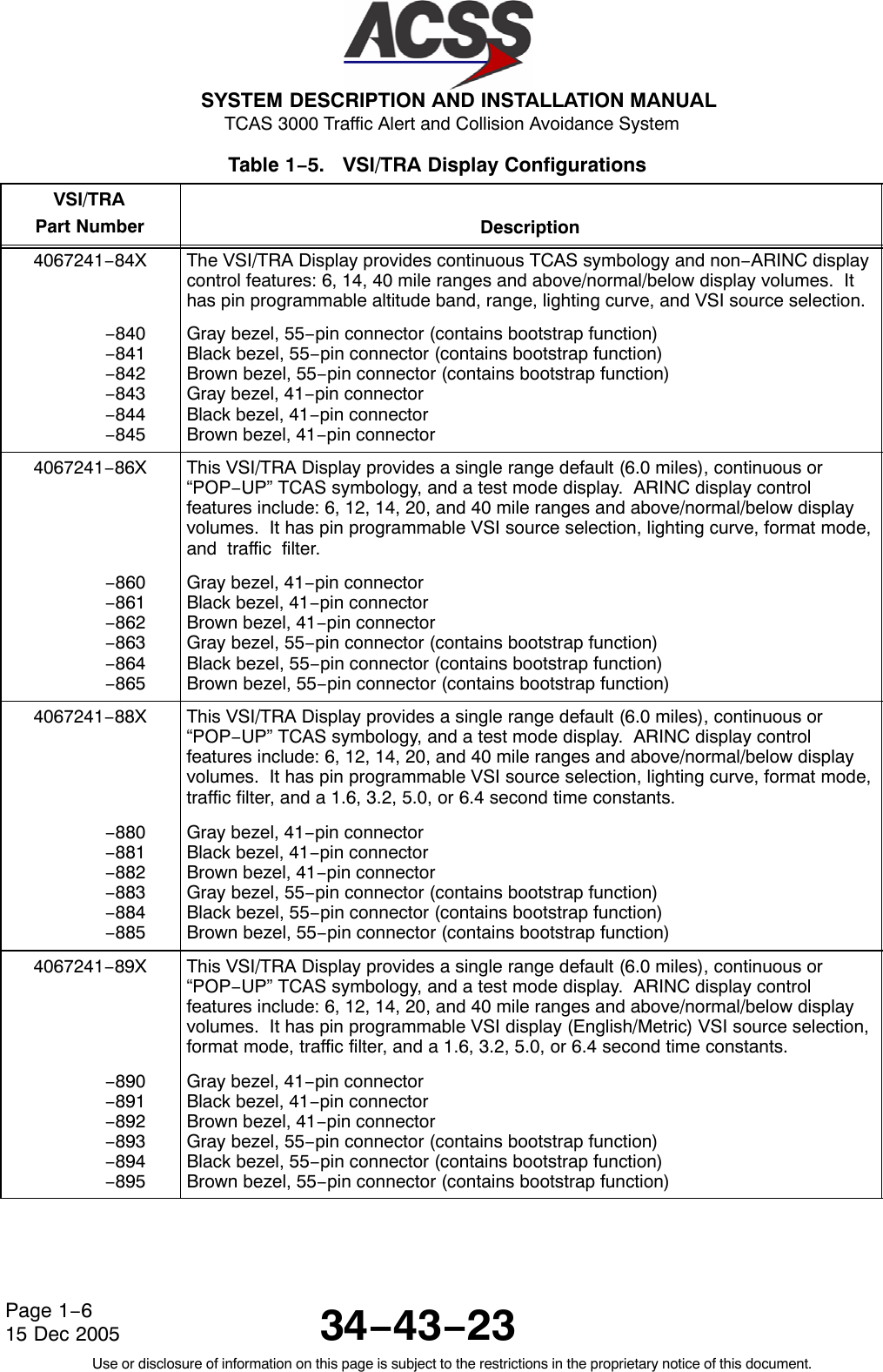
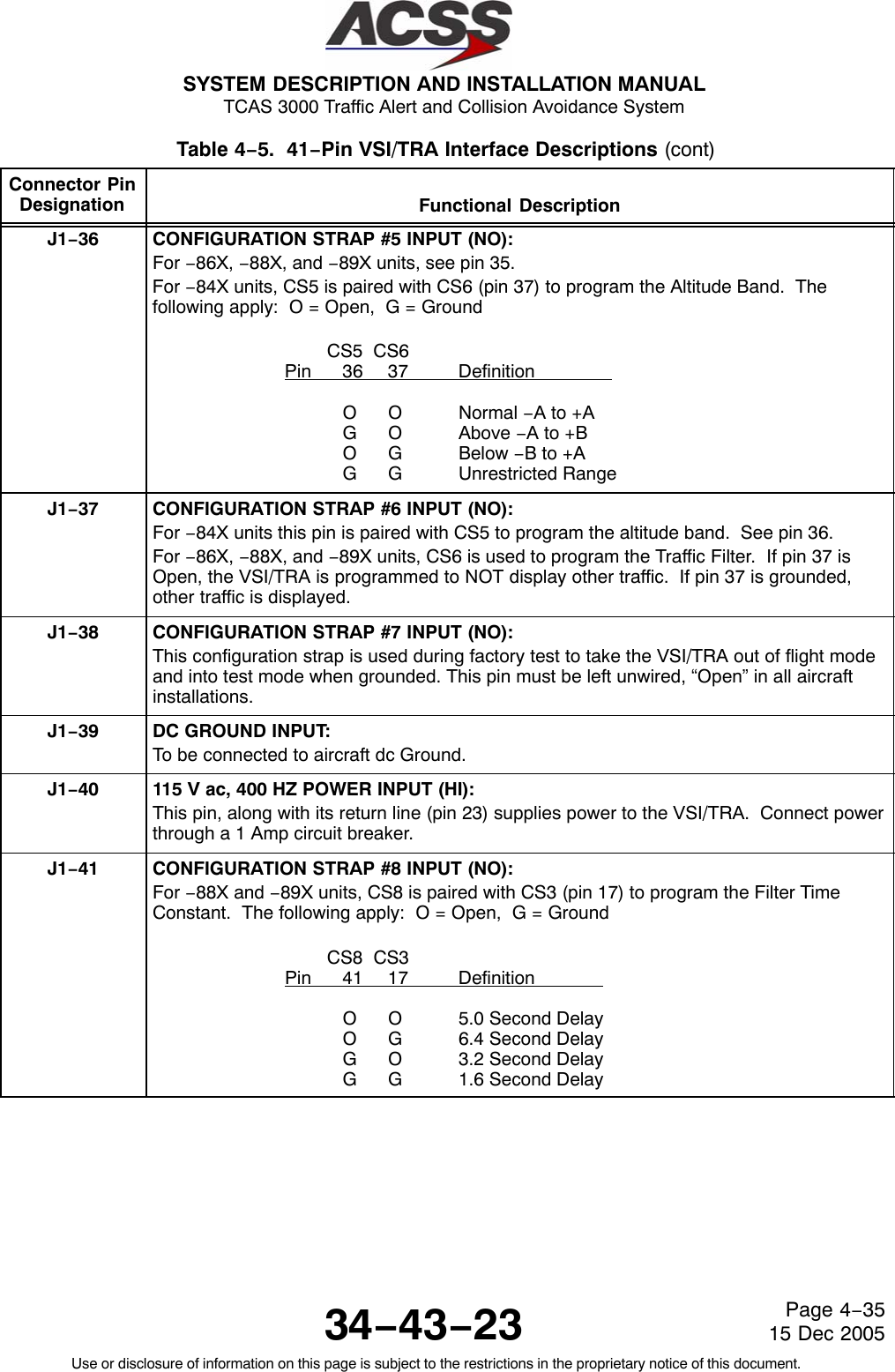
![SYSTEM DESCRIPTION AND INSTALLATION MANUAL TCAS 3000 Traffic Alert and Collision Avoidance System34−43−23Use or disclosure of information on this page is subject to the restrictions in the proprietary notice of this document.Page 4−3715 Dec 2005Table 4−6. 55−Pin VSI/TRA Interface Descriptions (cont)Connector PinDesignation Functional DescriptionJ1−12 VERTICAL SPEED NO. 1 VALID DISCRETE INPUT:The VSI/TRA receives a 28 V dc signal from an ARINC 575 or 565 air data computerindicating its valid operation. An “Open” at this pin indicates an invalid vertical speedsignal from ADC #1. This pin is only used when pins ( 2, 3, 8) or (9, 10, 11) are used andon the #1 VSI/TRA display. Also see pins 2, 10, and 11.J1−13, 14 R/C BOOTSTRAP OUTPUT: [J1−14 (HI), J1−13 (LO)]This two wire bus output sends ARINC 565 vertical speed data to the cross−side displaywhen the bootstrap mode is activated. These pins are connected to the ARINC 565Secondary Vertical Speed Input bus on the cross−side display as follows:J1−14 of the on−side display is connected to J1−6 of the cross−side display.J1−13 of the on−side display is connected to J1−1 of the cross−side display.J1−15 BOOTSTRAP COMMAND OUTPUT:This pin is connected to the Source Select #2 (SS2) discrete input, pin 29, within theVSI/TRA. The output provides an Open/28 V dc discrete that can be used to annunciatethe bootstrap function. This output is normally not used.J1−17 CONFIGURATION STRAP #5 INPUT (NO):For −84X units, CS5 is paired with CS6 (pin 37) to program the altitude band. Thefollowing apply: O = Open, G = Ground CS5 CS6Pin 17 18 DefinitionO O Normal −A to +AG O Above −A to +BO G Below −B to +AG G Unrestricted RangeFor −86X, −88X and −89X units, CS5 is paired with CS4 (pin 36) to program the DisplayFormat. The following apply: O = Open, G = Ground CS5 CS4Pin 17 36 Definition O O VSI/RA/TAO G VSI/RAG O VSI OnlyG G InvalidJ1−18 CONFIGURATION STRAP #6 INPUT (NO):For −84X units, see pin 17.For −86X, −88X, and −89X units CS6 is used to program the Traffic Filter. If pin 18 isOpen, the VSI/TRA is programmed to not display other traffic. If pin 18 is grounded,other traffic will be displayed.J1−19 CONFIGURATION STRAP #7 INPUT (NO):This configuration strap is used during factory test to take the VSI/TRA out offlight mode and into test mode when grounded. This pin must be left unwired,“Open” in all aircraft installations.](https://usermanual.wiki/ACSS-an-L-3-Communications-and-Thales/T3K-4M/User-Guide-718711-Page-206.png)
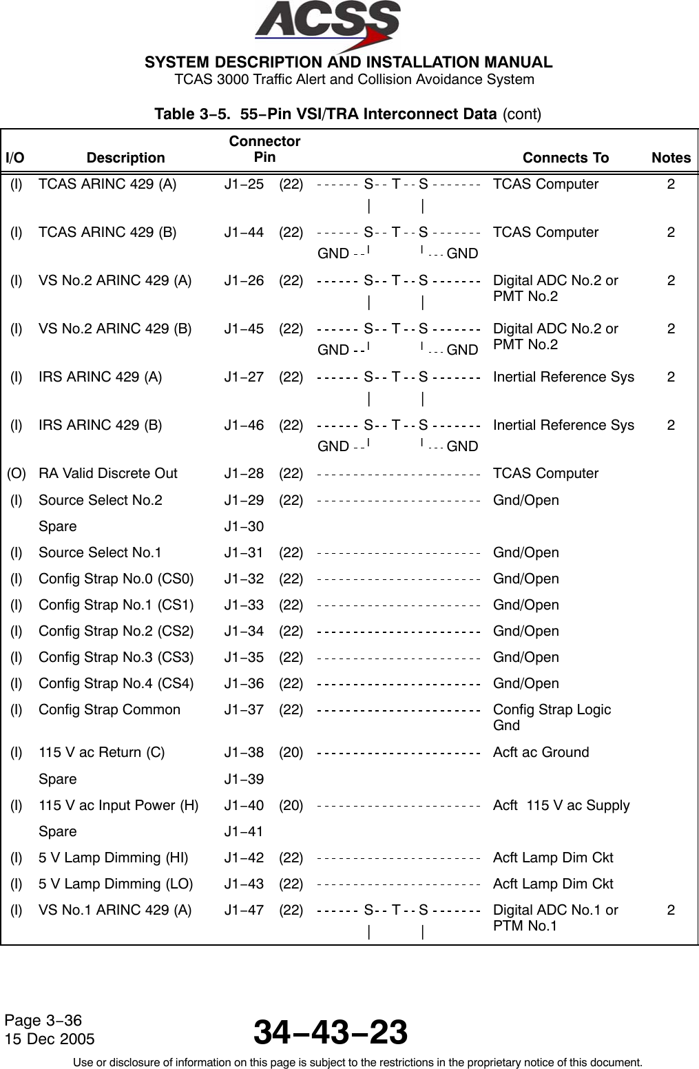
![SYSTEM DESCRIPTION AND INSTALLATION MANUAL TCAS 3000 Traffic Alert and Collision Avoidance System34−43−23Use or disclosure of information on this page is subject to the restrictions in the proprietary notice of this document.Page 4−3815 Dec 2005Table 4−6. 55−Pin VSI/TRA Interface Descriptions (cont)Connector PinDesignation Functional DescriptionJ1−20 CHASSIS GROUND INPUT:Connected to aircraft frame. Also used to connect ARINC cable shields to the chassis.J1−21 DC GROUND INPUT:To be connected to aircraft dc Ground.J1−22 CONFIGURATION STRAP #8 INPUT (NO):For −84X and −86X units, CS8 is not used and pin J1−22 must remain Open.For −88X and −89X units, CS8 is paired with CS3 (pin 35) to program the Filter TimeConstant. The following apply: O = Open, G = Ground CS8 CS3Pin 22 35 DefinitionO O 5.0 Second DelayO G 6.4 Second DelayG O 3.2 Second DelayG G 1.6 Second DelayJ1−23,24 REMOTE LIGHT SENSOR INPUT: (J1−23 HIGH, J1−24 LOW )This input at pins 23 and 24 provides a means of controlling the VSI/TRA backlighting via a remote light sensor already present in some aircraft (Douglas andBoeing). The VSI/TRA has its own built−in sensor and therefore a remote lightsensor need not be used in all installations. Program the VSI/TRA for a remotelight sensor, as described under pin 34 and 35.J1−25, 44 ARINC 429 TCAS BUS INPUT: [J1−25 (A), J1−44 (B)]This differential pair input is a high speed ARINC 429 bus (100K bit/second nominal) thatreceives Traffic and Resolution Advisory data supplied by the TCAS computerunit.J1−26, 45 ARINC 429 VERTICAL SPEED NO. 2 BUS INPUT: [J1−26 (A), J1−45 (B)]This differential pair input is a low speed bus (12.5K bits/second nominal) that receivesARINC 429 vertical speed data from the secondary (#2) digital ADC or the #2 PTM.J1−27, 46 ARINC 429 INERTIAL REFERENCE SYSTEM BUS INPUT: [J1−27 (A), J1−46 (B)]This differential pair input is a low speed ARINC 429 bus (12.5K bits/second nominal) thatreceives vertical speed data from an Inertial Reference System.J1−28 RA VALID DISCRETE OUTPUT:This output discrete indicates the ability of the VSI/TRA to perform as a resolutionadvisory and/or a traffic advisory display. If the VSI/TRA fails, this discrete presents anopen. Normal operation causes a ground. This discrete is monitored by the TCAScomputer unit.](https://usermanual.wiki/ACSS-an-L-3-Communications-and-Thales/T3K-4M/User-Guide-718711-Page-207.png)
![SYSTEM DESCRIPTION AND INSTALLATION MANUAL TCAS 3000 Traffic Alert and Collision Avoidance System34−43−23Use or disclosure of information on this page is subject to the restrictions in the proprietary notice of this document.Page 4−4015 Dec 2005Table 4−6. 55−Pin VSI/TRA Interface Descriptions (cont)Connector PinDesignation Functional DescriptionJ1−35 CONFIGURATION STRAP #3 INPUT (NO):For −86X units, CS3 is paired with CS2 to program the Lighting Curve. See pin 34.For −88X and −89X units, CS3 is paired with CS8 to program the Filter Time Constant.See pin 22.For −84X units, CS3 is paired with CS4 (pin 36) to program the display Range Format.The following applies: O = Open, G = Ground CS3 CS4Pin 35 36 Definition O O 14 Nautical Mile Range O G 6 Nautical Mile Range G O 40 Nautical Mile Range G G 6 Nautical Mile RangeJ1−36 CONFIGURATION STRAP #4 INPUT (NO):For −84X units, CS4 is paired with CS3 to program the Range Format. See pin 35.For −86X, −88X, and −89X units, CS4 is paired with CS5 to program the Display Format.See pin 17.J1−37 CONFIGURATION STRAP COMMON INPUT:This pin is the return line for the configuration strapping pins J1−17, 18, 19, 22, and J1−32thru 36. The VSI/TRA uses configuration strapping so unique aspects of anygiven installation may be identified and its functions supported. Eachconfiguration strap (CS) and its associated function becomes active whenconnected to program common (J1−37).J1−38 115 V ac, 400 HZ POWER INPUT (COMMON):See pin 40. Connect to aircraft AC ground.J1−40 115 V ac, 400 HZ POWER INPUT (HIGH):This pin, along with its return line (pin 38) supplies power to the VSI/TRA. Connect powerthrough a 1 Amp circuit breaker.J1−42, 43 5−VOLT LAMP DIMMING INPUT: (J1−42 LOW, J1−43 HIGH)The VSI/TRA monitors the cockpit lamp voltage bus at pins 42 and 43. This voltage maybe either ac or dc. The back lighting in the VSI/TRA is adjusted by and tracks this voltagefrom 0.5 volts to 5 volts. If this input falls below 0.5 volts or is absent, the VSI/TRA setsitself to a nominal level to prevent the display from going dark due to loss or failure of thelamp dimming bus.J1−47, 48 ARINC 429 VERTICAL SPEED NO. 1 BUS INPUT: [J1−47 (A), J1−48 (B)]This differential pair input is a low speed bus (12.5K bits/second nominal) that receivesARINC 429 vertical speed data from the primary (#1) digital ADC or the #1 PTM.J1−49 VERTICAL SPEED VALID DISCRETE OUTPUT:This discrete output sends bootstrap ARINC 565 vertical speed valid data to thecross−side display. The output is connected to the Vertical Speed Valid Input (pin J1−5)of the cross−side display.](https://usermanual.wiki/ACSS-an-L-3-Communications-and-Thales/T3K-4M/User-Guide-718711-Page-209.png)
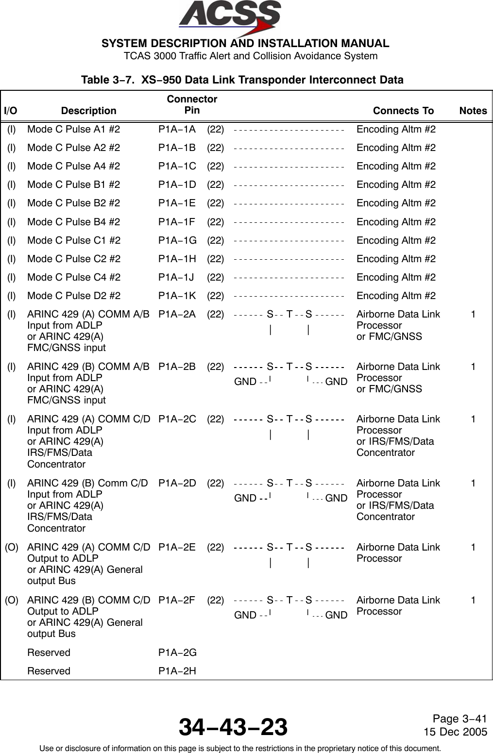
![SYSTEM DESCRIPTION AND INSTALLATION MANUAL TCAS 3000 Traffic Alert and Collision Avoidance System34−43−23Use or disclosure of information on this page is subject to the restrictions in the proprietary notice of this document.Page 4−4315 Dec 2005Table 4−8. XS−950 Data Link Transponder Interface Descriptions Connector PinDesignation Functional DescriptionP1A−1A THRUP1A−1K, ANDP1A−2KENCODING ALTIMETER #2 INPUTS:These Mode C pulse discrete inputs allow for altitude inputs from an encoding altimeterthat contains a discrete 11 wire interface. The standards for this interface are defined inARINC Characteristic 572, “Air Traffic Control Transponder”. The inputs use ground/openlogic levels.NOTE: Two encoding altimeters are required if the transponder is used with TCAS.P1A−2A, 2B ARINC 429 ADLP TO COMM A/B BUS INPUT: [P1A−2A (A), P1A−2B (B)]orARINC 429 FMC/GNSS InputFour ARINC 429 busses are provided for interfacing to a Mode S Airborne Data LinkProcessor (ADLP). The COMM A/B input and output busses are used for the transfer ofstandard length messages to and from the ADLP. The COMM C/D input and outputbusses are used for the transfer of extended length messages (ELM) to and from theADLP. P1A−2A and 2B can also be configured to a FMC/GNSS input. The standard forthis interface is defined on ARINC 718−A. For additional information on the FMC/GNSSinput, refer to ARINC 743A. This input is configured by grounding or oponing P1B−5H.P1A−2C, 2D ARINC 429 ADLP TO COMM C/D BUS INPUT: [P1A−2C (A), P1A−2D (B)]orARINC 429 IRS/RMS/Data ConcentratorSee pins P1A−2A, −2BP1A−2E, 2F ARINC 429 COMM C/D TO ADLP BUS OUTPUT: [P1A−2E (A), P1A−2F (B)]orARINC 429 General Output BusSee pins P1A−2A, −2BP1A−3B XPDR FAIL DISCRETE OUTPUT #2:This discrete output is set to annunciate an internal transponder failure or the Mode Saddress is illegal (All 0’s or 1’s). A ground logic threshold (<3.0 V dc) is output when thetransponder is operating normally, and an open logic threshold (resistance >100K ohms tounit ground) when a failure has occurred. The output is capable of sinking 200 mA ofcurrent. Connect this pin to the Control Panel XPDR FAIL #2 input.](https://usermanual.wiki/ACSS-an-L-3-Communications-and-Thales/T3K-4M/User-Guide-718711-Page-212.png)
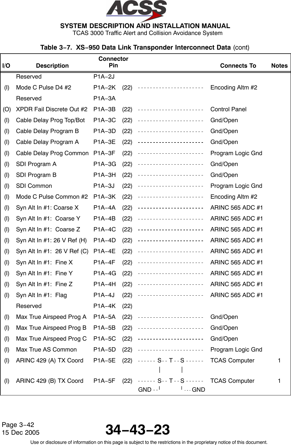
![SYSTEM DESCRIPTION AND INSTALLATION MANUAL TCAS 3000 Traffic Alert and Collision Avoidance System34−43−23Use or disclosure of information on this page is subject to the restrictions in the proprietary notice of this document.Page 4−4415 Dec 2005Table 4−8. XS−950 Data Link Transponder Interface Descriptions (cont)Connector PinDesignation Functional DescriptionP1A−3C,P1A−3D,P1A−3E,P1A−3FCABLE DELAY PROGRAM INPUTS:The Cable Delay Program Inputs are used to compensate for the difference inpropagation delays in the transponder due to antenna transmission line length differencesbetween the top and bottom antennas. The inputs use ground/open logic levels. TheCable Delay Program Common (pin P1A−3F) can be used to supply a ground. Program Pin Differential TransponderP1A−3C P1A−3D P1A−3E Delay AdjustmentOpen Open Open 0−50 nsec No ChangeOpen Open Ground 51−150 nsec Add Delay to Top ChannelOpen Ground Open 151−250 nsec Add Delay to Top ChannelOpen Ground Ground 251−350 nsec Add Delay to Top ChannelGround Open Open 0−50 nsec No ChangeGround Open Ground 51−150 nsec Add Delay to Bottom ChannelGround Ground Open 151−250 nsec Add Delay to Bottom ChannelGround Ground Ground 251−350 nsec Add Delay to Bottom ChannelThe differential delay column is the difference in the round trip cable delay between thetop and bottom antenna cables. The differential delay can be calculated as follows:[Top length in feet − Bottom length in feet] X [Characteristic Delay (nsec/foot)] X 2.P1A−3G,P1A−3H,P1A−3JSDI PROGRAM INPUTS:The SDI program inputs are used to identify the system number in the installation. Theinputs use ground/open logic levels. The SDI Common (pin P1A−3J) can be used tosupply a ground. Program PinP1A−3G P1A−3H DefinitionOpen Open Not Applicable (SDI = 00)Open Ground LRU System #1 (SDI = 01)Ground Open LRU System #2 (SDI = 10)Ground Ground LRU System #3 (SDI = 11)P1A−4A THRU P1A−4JARINC 565 ANALOG AIR DATA COMPUTER #1 INPUTS:These input pins allow for altitude information from an Analog Synchro Altitude Interfaceto be connected to the transponder. The standards for this interface are defined inARINC 565, “Subsonic Air Data System”.](https://usermanual.wiki/ACSS-an-L-3-Communications-and-Thales/T3K-4M/User-Guide-718711-Page-213.png)
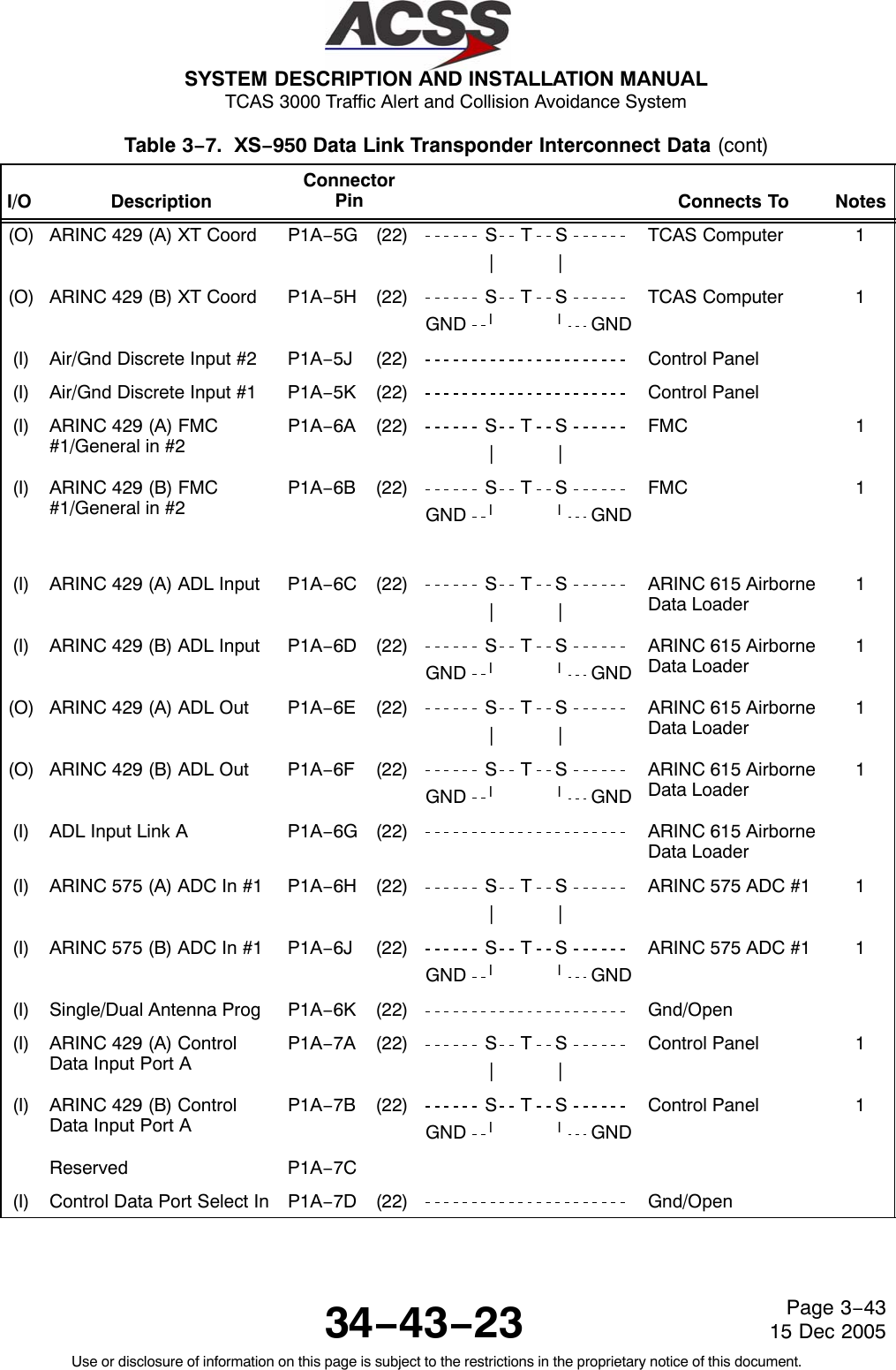
![SYSTEM DESCRIPTION AND INSTALLATION MANUAL TCAS 3000 Traffic Alert and Collision Avoidance System34−43−23Use or disclosure of information on this page is subject to the restrictions in the proprietary notice of this document.Page 4−4515 Dec 2005Table 4−8. XS−950 Data Link Transponder Interface Descriptions (cont)Connector PinDesignation Functional DescriptionP1A−5A,P1A−5B,P1A−5C,P1A−5DMAXIMUM TRUE AIRSPEED PROGRAM INPUTS:The Maximum True Airspeed inputs are used for strapping the maximum cruise airspeedcapability of the aircraft. The inputs use ground/open logic levels. The Max TrueAirspeed Common (pin P1A−5D) can be used to supply a ground. Program PinP1A−5A P1A−5B P1A−5C DefinitionOpen Open Open No Maximum Airspeed AvailableGround Open Open Maximum Airspeed ≤75 KnotsOpen Ground Open Maximum Airspeed >75 and ≤150 KnotsGround Ground Open Maximum Airspeed >150 and ≤300 KnotsOpen Open Ground Maximum Airspeed >300 and ≤600 KnotsGround Open Ground Maximum Airspeed >600 and ≤1200 KnotsOpen Ground Ground Maximum Airspeed >1200 KnotsGround Ground Ground Not AssignedP1A−5E, 5F ARINC 429 TX COORDINATION BUS INPUT: (P1A−5E [A], P1A−5F [B])Two high speed ARINC 429 busses (100K bits/second nominal) are provided to interfacebetween the transponder and a TCAS computer unit. The standards for this interface aredefined in ARINC Characteristic 735, “Traffic Alert and Collision Avoidance System”.P1A−5G, 5H ARINC 429 XT COORDINATION BUS OUTPUT: (P1A−5G [A], P1A−5H [B])See pins P1A−5E, 5F.P1A−5J AIR / GROUND #2 DISCRETE INPUT:This pin and AIR / GROUND #1 Discrete Input (pin P1A−5K) provide a method for thetransponder to automatically determine the Air/Ground status of the aircraft. The status isused in replies to Mode S interrogations and to inhibit replies to certain types ofinterrogations. Both inputs use ground/open logic, where a Ground specifies an “On theGround” condition and an Open specifies an “In the Air” condition.When this pin is connected to the Air/Ground Relay (Squat Switch), the transponder willnot reply to ATCRBS, ATCRBS/Mode S All Call, or Mode S All Call when the input is setfor “On the Ground”. This input should be connected to the Air/Ground Relay for normaloperation.P1A−5K AIR / GROUND #1 DISCRETE INPUT:See pin P1A−5J.When this pin is connected to the Air/Ground Relay (Squat Switch), the transponderreplies to all types of interrogations irregardless of the state of the input. This input allowsthe transponder to reply during a ramp test.P1A−6A, 6B FMC #1/Gineral In #2This differential pair input supports common existing FMC configurations where flight ID isavailable on the FMC General Purpose output bus but the other Enhanced data is onlyavailable on a display bus.](https://usermanual.wiki/ACSS-an-L-3-Communications-and-Thales/T3K-4M/User-Guide-718711-Page-214.png)
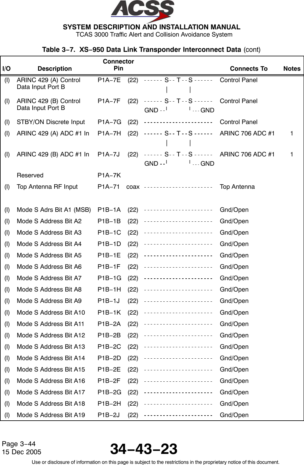
![SYSTEM DESCRIPTION AND INSTALLATION MANUAL TCAS 3000 Traffic Alert and Collision Avoidance System34−43−23Use or disclosure of information on this page is subject to the restrictions in the proprietary notice of this document.Page 4−4615 Dec 2005Table 4−8. XS−950 Data Link Transponder Interface Descriptions (cont)Connector PinDesignation Functional DescriptionP1A−6C, 6D ARINC 615 AIRBORNE DATA LOADER BUS INPUT: (P1A−6C [A], P1A−6D [B])The Airborne Data Loader interface consists of two high speed ARINC 429 busses (100Kbits/second nominal) and a ground/open logic discrete (pin P1A−6G). The interfaceallows for operational transponder software to be loaded into the unit through an onboarddata loader. The standards for this interface are defined in ARINC 615 “AirborneComputer High Speed Data Loader”.P1A−6E, 6F ARINC 615 AIRBORNE DATA LOADER BUS OUTPUT: (P1A−6E [A], P1A−6F [B])See pins P1A−6C, 6DP1A−6G ADL INPUT LINK A DISCRETE INPUT:See pins P1A−6C, 6DP1A−6H, 6J ARINC 575 AIR DATA COMPUTER #1 INPUT: (P1A−6H [A], P1A−6J [B])This differential pair input is a low speed ARINC 575 bus (12.5K bits/second nominal) thatcan be used to input altitude information from an ARINC 575 Air Data System. Thestandards for this interface are defined in ARINC Characteristic 575, “Subsonic Air DataSystem (Digital) DADS”.P1A−6K SINGLE / DUAL ANTENNA PROGRAM INPUT:This pin allows for installation of the transponder in a system with a single bottommounted antenna or dual top and bottom mounted antennas. The input usesground/open logic as follows:Ground = Single Bottom Mounted Antenna ConfigurationOpen = Diversity Antenna ConfigurationP1A−7A, 7B ARINC 429 CONTROL DATA PORT A BUS INPUT: (P1A−7A [A], P1A−7B [B])The control panel data can be input into the transponder on either of two low speedARINC 429 busses. (Ports A and B). The control data is contained in labels 013, 015,and 016. The port is selected by the CONTROL DATA PORT SELECT Discrete Input(pin PIA−7D).P1A−7D CONTROL DATA PORT SELECT INPUT:See pins P1A−7A, 7B.This discrete input is used to select which port is used to input control data to thetransponder. This input uses a ground/open logic as follows:Ground Specifies Port AOpen Specifies Port BP1A−7E, 7F ARINC 429 CONTROL DATA PORT B BUS INPUT: (P1A−7E [A], P1A−7F [B])See pins P1A−7A, 7B.P1A−7G STANDBY / ON DISCRETE INPUT:This discrete input is connected to the Control Panel STANDBY/ON output. The inputselects the active or standby status of the transponder. A ground causes the transponderto be in standby, and an open causes the transponder to be active.](https://usermanual.wiki/ACSS-an-L-3-Communications-and-Thales/T3K-4M/User-Guide-718711-Page-215.png)
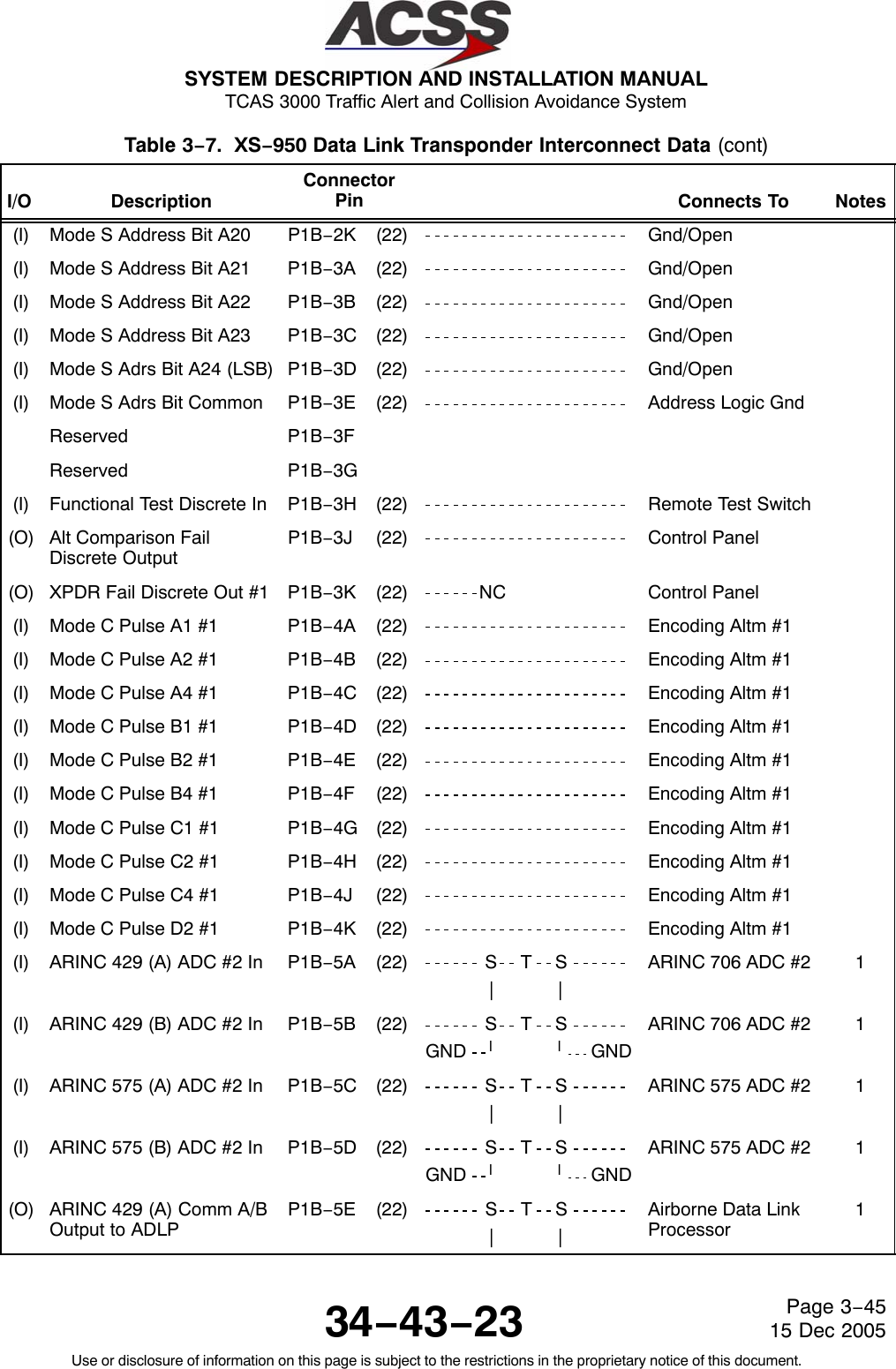
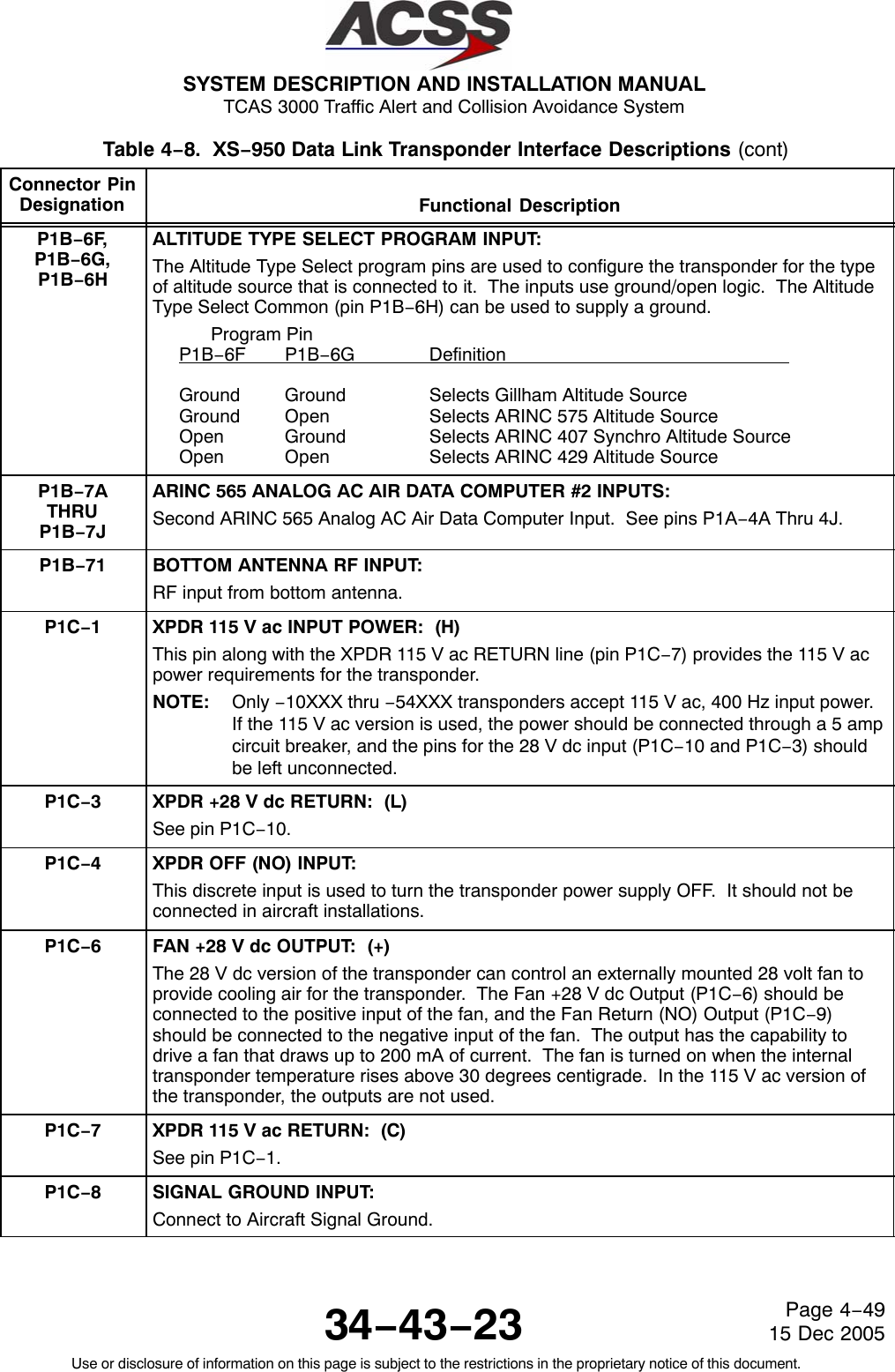
![SYSTEM DESCRIPTION AND INSTALLATION MANUAL TCAS 3000 Traffic Alert and Collision Avoidance System34−43−23Use or disclosure of information on this page is subject to the restrictions in the proprietary notice of this document.Page 4−4715 Dec 2005Table 4−8. XS−950 Data Link Transponder Interface Descriptions (cont)Connector PinDesignation Functional DescriptionP1A−7H, 7J ARINC 429 ADC #1 BUS INPUT: (P1A−7H [A], P1A−7J [B])The altitude information for the transponder can be obtained from an ARINC 706 Air DataSystem through two low speed ARINC 429 data busses. The standards for this interfaceare defined in ARINC Characteristic 706, “Mark 5 Subsonic Air Data System”.This differential pair input is a low speed ARINC 429 bus that inputs uncorrected pressurealtitude (ARINC label 203) from an altitude source. Also see pins P1B−5A, 5B.P1A−71 TOP ANTENNA RF INPUT:RF input from top antenna.P1B−1ATHRUP1B−3EMODE S ADDRESS INPUTS:The Mode S Address is a unique 24−bit code assigned to each aircraft. Pins P1B−1Athru P1B−3E are used to program this 24−bit binary number. The inputs must be setaccording to this binary number representation. Each binary 1 represents a Grounded pinand each binary 0 represents an Open pin. Pin P1B−1A represents the most significantbit (MSB) of the binary number and pin P1B−3D represents the least significant bit (LSB)of the binary number.NOTE: An address of all 0’s or all 1’s is an illegal address, and can cause the aircraft tobe invisible to TCAS II equipped aircraft in flight. Never use an illegal addressfor an installed system.P1B−3H FUNCTIONAL TEST DISCRETE INPUT:This discrete input is used to put the transponder in a functional test mode. Thefunctional test that is performed by the transponder is equivalent to a test that is initiatedfrom the control panel. The input uses ground/open logic as follows:Ground = Initiate Functional TestOpen = Normal OperationP1B−3J ALTITUDE COMPARISON FAIL DISCRETE OUTPUT:This discrete output annunciates a comparison failure in the altitude data for thetransponder if Gillham altitude data is selected. The output annunciates a failure if thetwo altitude sources are not within 500 feet.The output drives a ground logic threshold (voltage of less than 3.0 V dc) when thealtitude is valid, and an open logic threshold (resistance is greater than 100K ohms to unitground) when a failure has occurred. The output is capable of sinking 200 mA of current.P1B−3K XPDR FAIL DISCRETE OUTPUT #1:This discrete output is set to annunciate an internal transponder failure or that the Mode Saddress is illegal (All 0’s or 1’s). The output will source a voltage of greater than 5.0 V dcat 100 mA of current when a failure has occurred, and an open circuit (resistance ofgreater than 100k ohms to unit ground) when the transponder is operating normally. Theoutput contains diode isolation. Connect this pin to the Control Panel XPDR FAIL #1input.P1B−4A THRUP1B−4K, ANDP1B−5KENCODING ALTIMETER #1 INPUTS:First of two Encoding Altimeter interfaces. See pins P1A−1A thru 4K and P1A−2K.](https://usermanual.wiki/ACSS-an-L-3-Communications-and-Thales/T3K-4M/User-Guide-718711-Page-216.png)
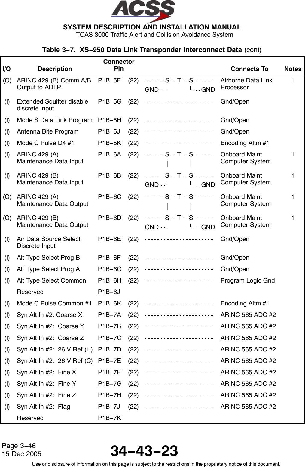
![SYSTEM DESCRIPTION AND INSTALLATION MANUAL TCAS 3000 Traffic Alert and Collision Avoidance System34−43−23Use or disclosure of information on this page is subject to the restrictions in the proprietary notice of this document.Page 4−4815 Dec 2005Table 4−8. XS−950 Data Link Transponder Interface Descriptions (cont)Connector PinDesignation Functional DescriptionP1B−5A, 5B ARINC 429 AIR DATA COMPUTER #2 BUS INPUT: (P1B−5A [A], P1B−5B [B])Second ARINC 429 Air Data Computer bus input. See pins P1A−7H, 7J.P1B−5C, 5D ARINC 575 AIR DATA COMPUTER #2 BUS INPUT: (P1B−5C [A], P1B−5D [B])Second ARINC 575 Air Data Computer bus input. See pins P1A−6H, 6J.P1B−5E, 5F ARINC 429 COMM A/B TO ADLP BUS OUTPUT: (P1B−5E [A], P1B−5F [B])See pins P1A−2A, 2B.P1B−5G Extended Squitter DisableThis input is used to disable all Extended Squitter functions:Ground = All functions disabledOpen = All functions enabledP1B−5H MODE S DATA LINK PROGRAM INPUT:This program input specifies if the transponder is connected to an Airborne Data LinkProcessor (ADLP) Unit. The input uses ground/open logic as follows:Ground = ADLP is InstalledOpen = ADLP is not installedP1B−5J ANTENNA BITE PROGRAM INPUT:This program input specifies if the transponder is to perform a built−in test to the antennasubsystem. The transponder performs a continuity check of the antenna to make sure itis not an open circuit. The input uses ground/open logic as follows:Ground = Enables Antenna Subsystem TestOpen = Disables Antenna Subsystem TestP1B−6A, 6B ARINC 429 MAINTENANCE DATA BUS INPUT: (P1B−6A [A], P1B−6B [B])Two low speed ARINC 429 busses (12.5K bits/second nominal) are provided to interfacebetween the transponder and an onboard maintenance system. The maintenancecomputer interface is designed to work with all airframe models and types.P1B−6C, 6D ARINC 429 MAINTENANCE DATA BUS OUTPUT: (P1B−6C [A], P1B−6D [B])See pins P1B−6A, 6B.P1B−6E AIR DATA SOURCE SOURCE SELECT DISCRETE INPUT:The transponder contains dual inputs for all types of altitude sources. This discrete inputspecifies which of the two inputs are used to obtain altitude information.Ground = Altitude Source No. 2Open = Altitude Source No. 1](https://usermanual.wiki/ACSS-an-L-3-Communications-and-Thales/T3K-4M/User-Guide-718711-Page-217.png)
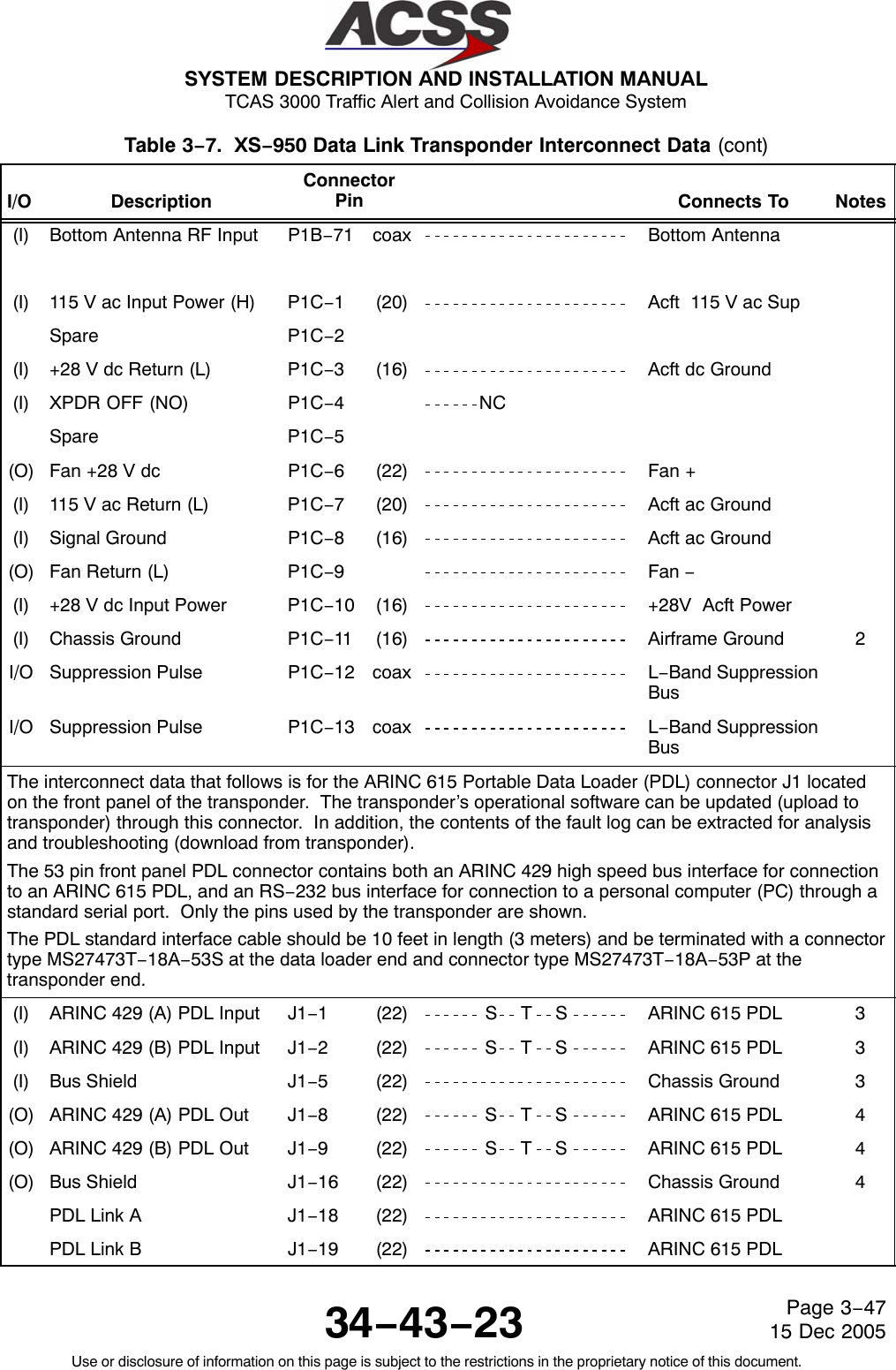
![SYSTEM DESCRIPTION AND INSTALLATION MANUAL TCAS 3000 Traffic Alert and Collision Avoidance System34−43−23Use or disclosure of information on this page is subject to the restrictions in the proprietary notice of this document.Page 4−5015 Dec 2005Table 4−8. XS−950 Data Link Transponder Interface Descriptions (cont)Connector PinDesignation Functional DescriptionP1C−9FAN RETURN (NO): (−)See pin P1C−6.P1C−10 XPDR +28 V dc INPUT POWER: (H)This pin along with the +28 V dc RETURN line (P1C−3) provide the 28 V dc powerrequirements for the transponder.NOTE: Only −55XXX thru −99XXX transponders accept 28 V dc input power. If the 28V dc version is used, the power should be connected through an 8 amp circuitbreaker, and the pins for the 115 V ac input (P1C−1 and P1C−7) should be leftunconnected.P1C−11 CHASSIS GROUND INPUT:Connect to aircraft frame.P1C−12,P1C−13MUTUAL SUPPRESSION BUS INPUT/OUTPUT:L−Band suppression coax must be RG−142 or equivalent coaxial cable. P1C−12 andP1C−13 are connected internally. Connection to only one pin is required.The Interface descriptions that follow are for the 53−pin ARINC 615 Portable Data Loader connectorJ1 mounted on the front panel of the transponder. These descriptions are used to make up thecable that is used to interface between the transponder and the ARINC 615 Data Loader or aRS−232 PC Serial Port.J1−1, 2 XPDR ARINC 429 PDL BUS INPUT: (J1−1 [A], J1−2 [B])This differential pair input is a high speed ARINC 429 bus (100K bits/second nominal) isused to input data from the data loader to the transponder. The standards for thisinterface are defined in ARINC 615 “Airborne Computer High Speed Data Loader”.These pins should be connected to pins 1 and 2 of the PDL cable interface.J1−5INPUT BUS SHIELD:The shields from the input bus (J1−1, 2) should be connected to this pin.J1−8, 9 XPDR ARINC 429 PDL BUS OUTPUT: (J1−8 [A], J1−9 [B])This differential pair output is a high speed ARINC 429 bus (100K bits/second nominal)used to output data from the transponder to the data loader. The standards for thisinterface are defined in ARINC 615 “Airborne Computer High Speed Data Loader”.These pins should be connected to pins 8 and 9 of the PDL cable interface.J1−16 OUTPUT BUS SHIELD:The shields from the output bus (J1−8, 9) should be connected to this pin.J1−18 PDL LINK A:Connect this pin to pin 18 of the PDL cable interface.J1−19 PDL LINK B:Connect this pin to pin 19 of the PDL cable interface.](https://usermanual.wiki/ACSS-an-L-3-Communications-and-Thales/T3K-4M/User-Guide-718711-Page-219.png)
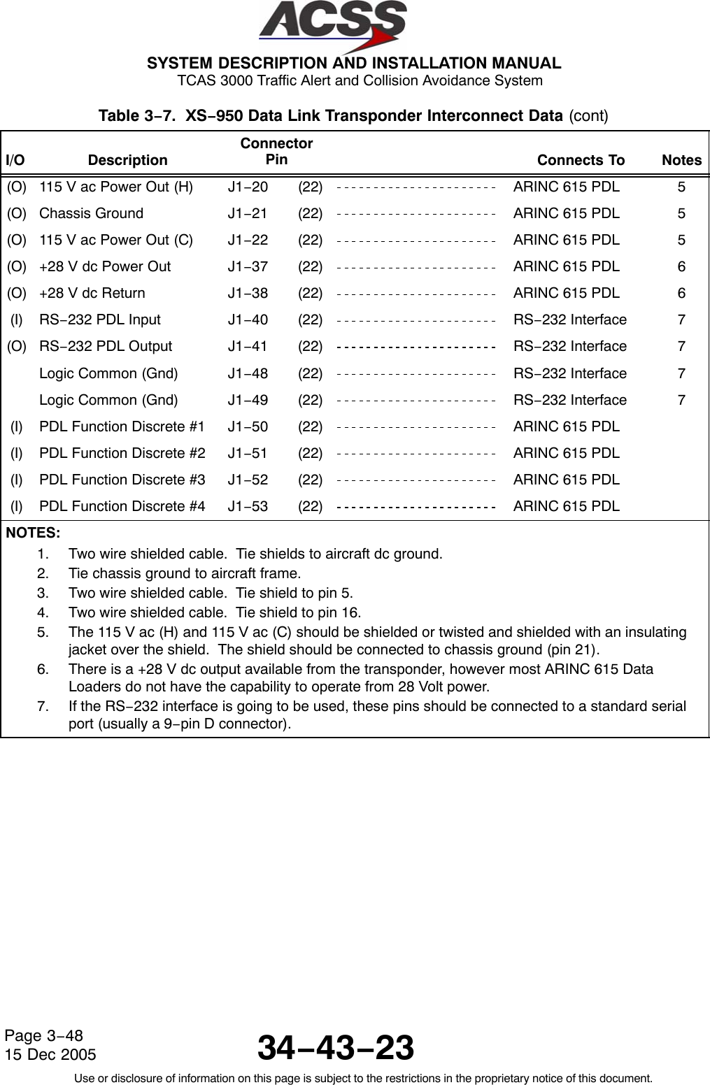
![SYSTEM DESCRIPTION AND INSTALLATION MANUAL TCAS 3000 Traffic Alert and Collision Avoidance System34−43−23Use or disclosure of information on this page is subject to the restrictions in the proprietary notice of this document.Page 4−5115 Dec 2005Table 4−8. XS−950 Data Link Transponder Interface Descriptions (cont)Connector PinDesignation Functional DescriptionJ1−20, 22 115 V ac POWER OUTPUT: (J1−20 [H], J1−22 [C])These power output pins provide the 115 V ac operating power for the data loader.NOTE: Only the 115 V ac version transponders provide this output. If a 28 V dc versiontransponder is installed, either the data loader must be able to operate from 28V dc or the data loader 115 V ac input power must be connected to a sourceexternal to the transponder.The 115 V ac (H) and 115 V ac (C) should be shielded or twisted and shielded with aninsulating jacket over the shield. The shield should be connected to chassis ground (pin21).J1−21 CHASSIS GROUND:Connect 115 V ac power shields to this pin.J1−37, 38 28 V dc POWER OUTPUT: (J1−37 [HI], J1−38 [LO])These power output pins provide the 28 V dc operating power for the data loader. Thesepins are used only if the data loader operates from 28 V dc.J1−40J1−41J1−48,49RS−232 PDL INPUT:RS−232 PDL OUTPUTLOGIC COMMON (Gnd)These pins would be connected to an RS−232 Serial Port as follows. Most RS−232Serial Ports use either a 9 pin RS−232 (COM) connector or a 25 pin RS−232 (COM)connector.ARINC 615 PC COM1 OR COM2 PC COM1 OR COM2CONNECTOR PIN 9 PIN CONNECTOR 25 PIN CONNECTOR 40 PC TX (pin 3) PC TX (pin 2) 41 PC RX (pin 2) PC RX (pin 3) 48 or 49 Ground (pin 5) Ground (pin 7)NOTE: When using a RS−232 interface, transponder pin J1−18 (Link A) and pin J1−19(Link B) must be connected (tied together) to do a software upload. The pinsshould be open to verify the software status.J1−50J1−51J1−52J1−53PDL FUNCTION DISCRETE #1 INPUT:PDL FUNCTION DISCRETE #2 INPUT:PDL FUNCTION DISCRETE #3 INPUT:PDL FUNCTION DISCRETE #4 INPUT:These pins are used to receive discrete functional information from the data loader.These pins should be connected to the PDL cable interface.](https://usermanual.wiki/ACSS-an-L-3-Communications-and-Thales/T3K-4M/User-Guide-718711-Page-220.png)
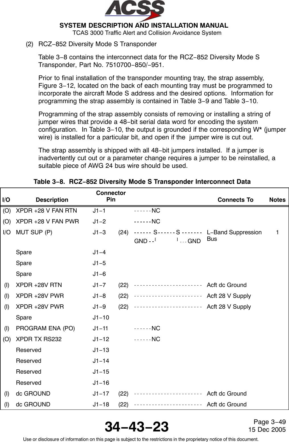
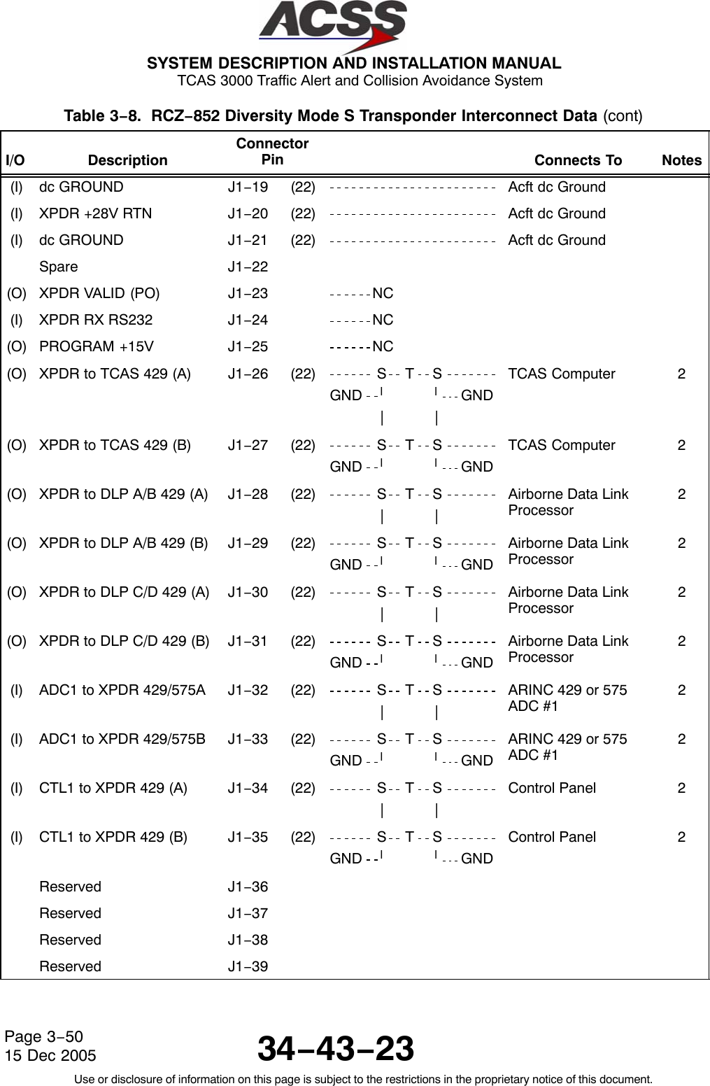
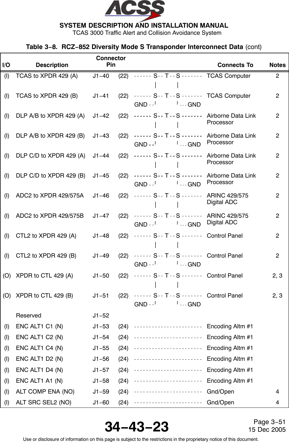
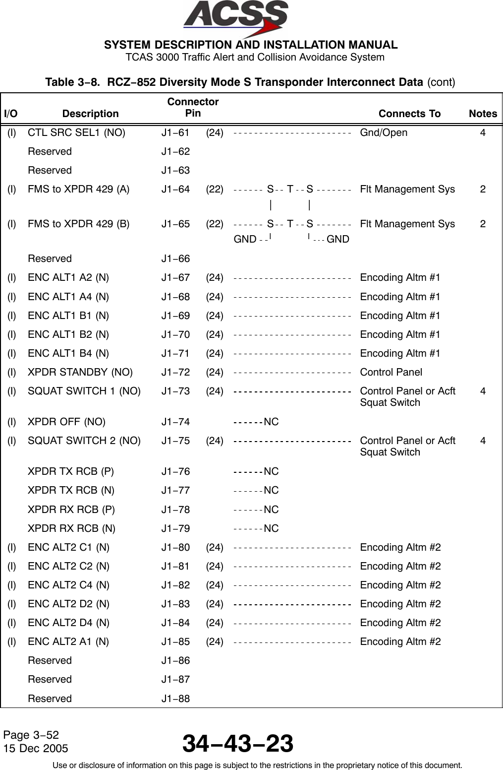
![SYSTEM DESCRIPTION AND INSTALLATION MANUAL TCAS 3000 Traffic Alert and Collision Avoidance System34−43−23Use or disclosure of information on this page is subject to the restrictions in the proprietary notice of this document.Page 4−5215 Dec 2005Table 4−9. RCZ−852 Diversity Mode S Transponder Interface Descriptions Connector PinDesignation Functional DescriptionJ1−1, 2 XPDR +28 V FAN PWR & +28V FAN RTN: (J1−1 LOW, J1−2 HIGH)The fan discrete outputs supply a switched, filtered +28 volts for a dc fan. The RCZ−852Transponder has an internal fan built into the unit, so external cooling is not required.Pins J1−1 and J1−2 should not be connected.J1−3MUTUAL SUPPRESSION BUS I/O:This bus is a single conductor, shielded bidirectional line that connects to all aircraftL−Band equipment. It is used to desensitize the associated receiver inputs whiletransmitting.J1−7XPDR +28 V RTN:See pins 8, 9.J1−8J1−9XPDR +28 V PWR:These pins along with there return lines (J1−7 and J1−20) provide the 28 volt powerrequirements for the transponder.J1−11 PROGRAM ENABLE INPUT:Bench test function. Do not connect this pin in aircraft installations.J1−12 XPDR RS232 TX OUTPUT:Bench test function. Do not connect this pin in aircraft installations.J1−17, J1−18J1−19, J1−21DC GROUND INPUT:To be connected to aircraft dc ground.J1−23 XPDR VALID (PO) OUTPUT:This discrete outputs the status of the transponder continuous monitor tests. It is thesame as the XPDR VALID (NO) output (J1−100) except the discrete is a positive/openlogic. A +28 V dc (200 mA maximum) is provided when the transponder is operationaland an active transponder mode is selected. An Open (>100K ohms resistance toground) output is provided when the transponder has failed or the standby mode isselected.J1−24 XPDR RS232 RX INPUT:Bench test function. Do not connect this pin in aircraft installations.J1−25 PROGRAM +15 V OUTPUT:Bench test function. Do not connect this pin in aircraft installations.J1−26, 27 XPDR TO TCAS ARINC 429 BUS OUTPUT: (J1−26 [A], J1−27 [B])This differential pair output is a high speed ARINC 429 bus (100K bits/second nominal)that sends data to the TCAS computer unit. The data bus conforms to the ARINC 718−Aand ARINC 735 standards for TCAS to transponder interface.J1−28, 29 XPDR TO DLP A/B ARINC 429 BUS OUTPUT: (J1−28 [A], J1−29[B])This differential pair output is a high speed ARINC 429 bus (100K bits/second nominal)that sends data to an airborne data link processor (ADLP) system. The data bus is usedto transfer COMM−A and COMM−B messages between the two systems and conforms tothe ARINC 718−A standard for ADLP to transponder interface.](https://usermanual.wiki/ACSS-an-L-3-Communications-and-Thales/T3K-4M/User-Guide-718711-Page-221.png)
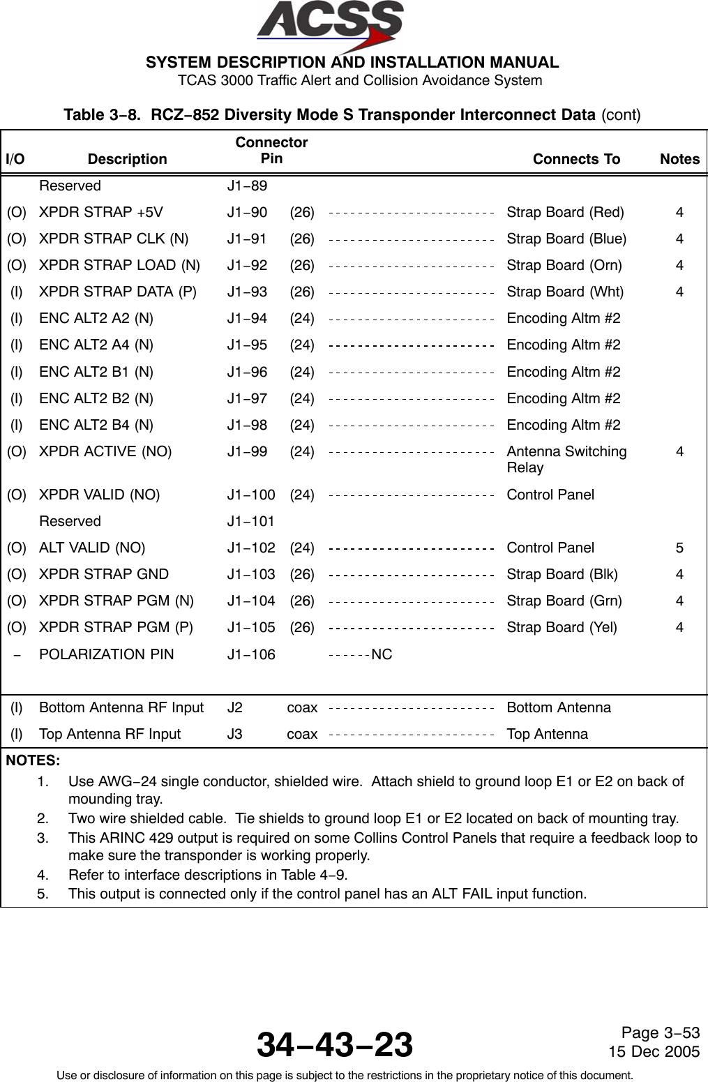
![SYSTEM DESCRIPTION AND INSTALLATION MANUAL TCAS 3000 Traffic Alert and Collision Avoidance System34−43−23Use or disclosure of information on this page is subject to the restrictions in the proprietary notice of this document.Page 4−5315 Dec 2005Table 4−9. RCZ−852 Diversity Mode S Transponder Interface Descriptions (cont)Connector PinDesignation Functional DescriptionJ1−30,31 XPDR TO DLP C/D ARINC 429 BUS OUTPUT: (J1−30 [A], J1−31 [B])This differential pair output is a high speed ARINC 429 bus (100K bits/second nominal)that sends data to an airborne data link processor (ADLP) system. The data bus is usedto transfer COMM−C and COMM−D messages between the two systems and conformsto the ARINC 718−A standard for ADLP to transponder interface.J1−32, 33 ADC1 TO XPDR ARINC 429/575 BUS INPUT: (J1−32 [A], J1−33 [B])This differential pair input is a low speed ARINC 429 or 575 bus that inputs uncorrectedpressure altitude (ARINC label 203) from an altitude source. The input accepts eitherARINC 429 or 575 data format, which is selected by the altitude source straps (W33,W34) on the Strap Assembly. The ALT SRC SEL2 (NO) discrete, pin 60, selects eitherADC1 or ADC2.J1−34, 35 CTL1 TO XPDR ARINC 429 BUS INPUT: (J1−34 [A], J1−35 [B])The transponder can receive data from the control panel(s) on the CTL1 TO XPDR andCTL2 TO XPDR data busses. The bus used, is selected by the CTL SRC SEL1 (NO)DISCRETE. See pin 61. The data bus not selected will not be processed. Thesedifferential pair inputs are low speed ARINC 429 busses (12.5K bits/second nominal) thattransmits tuning information from the control panel to the transponder. The transponderexpects to receive ARINC labels 016 and 031 at an update rate of 100 to 200milliseconds. Also see CTL2 TO XPDR ARINC 429 bus input (pins 48 and 49).J1−40, 41 TCAS TO XPDR ARINC 429 BUS INPUT: (J1−40 [A], J1−41 [B])This differential pair input is a high speed ARINC 429 bus (100K bit/second nominal) thatreceives data from a TCAS computer unit. The data bus conforms to the ARINC 718−Aand ARINC 735 standards for TCAS to transponder interface.J1−42, 43 DLP A/B TO XPDR ARINC 429 BUS INPUT: (J1−42 [A], J1−43 [B])This differential pair input is a high speed ARINC 429 bus (100K bits/second nominal) thatreceives data from an airborne data link processor (ADLP) system. The data bus is usedto transfer COMM−A and COMM−B messages between the two systems and conforms tothe ARINC 718−A standard for ADLP to transponder interface.J1−44, 45 DLP C/D TO XPDR ARINC 429 BUS INPUT: (J1−44 [A], J1−45 [B])This differential pair input is a high speed ARINC 429 bus (100K bits/second nominal) thatreceives data from an airborne data link processor (ADLP) system. The data bus is usedto transfer COMM−C and COMM−D messages between the two systems and conformsto the ARINC 718−A standard for ADLP to transponder interface.J1−46,47 ADC2 TO XPDR ARINC 429/575 BUS INPUT: (J1−46 [A], J1−47 [B])See pins J1−32, 33J1−48, 49 CTL2 TO XPDR ARINC 429 BUS INPUT: (J1−48 [A], J1−49 [B])See pins J1−34, 35J1−50, 51 XPDR TO CTL ARINC 429 BUS OUTPUT: (J1−50 [A], J1−51 [B])This differential pair output is a low speed ARINC 429 bus (12.5K bits/second) thattransmits control panel input data back to the control panel for verification purposes.These output pins are connected only on some Collins control panels that requirefeedback from the transponder to make sure it is operating properly.](https://usermanual.wiki/ACSS-an-L-3-Communications-and-Thales/T3K-4M/User-Guide-718711-Page-222.png)
![SYSTEM DESCRIPTION AND INSTALLATION MANUAL TCAS 3000 Traffic Alert and Collision Avoidance System34−43−23Use or disclosure of information on this page is subject to the restrictions in the proprietary notice of this document.Page 4−5415 Dec 2005Table 4−9. RCZ−852 Diversity Mode S Transponder Interface Descriptions (cont)Connector PinDesignation Functional DescriptionJ1−53 thru 58,J1−67 thru 71ENCODING ALTIMETER NO.1 ELEVEN BIT INPUT:Transponder input from Encoding Altimeter No. 1. These eleven lines from the altitudeencoder comprise an 11−bit word representative of the aircraft altitude.J1−59 ALT COMP ENA (NO) DISCRETE INPUT:This discrete input enables or disables altitude comparison when dual Gillham altitudesources are selected via the ALTITUDE SOURCE strap. If comparison is enabled (J1−59Grounded), the two altitude sources (ENC ALT1 and ENC ALT2) are compared, and areconsidered valid if they are within 500 feet. If the altitude comparison is enabled and itfails, the altitude data is considered invalid in Mode S replies and altitude data sent toTCAS. If comparison is disabled (J1−59 Open), only the selected altitude source is used.This discrete has no effect if ARINC 429 or 575 altitude sources are used.NOTE: For installations with TCAS that use Gillham encoding altimeter sources, twoencoding altimeter sources must be used, and pin J1−59 must be enabled(Grounded).J1−60 ALT SRC SEL2 (NO) DISCRETE INPUT:This discrete input allows selection of one of two altitude sources. An Open causes thetransponder to use altitude source No.1, and a Ground causes the transponder to usealtitude source No.2. The altitude data sent to TCAS and used for transponder replies isderived from the selected source.J1−61 CTL SRC SEL1 (NO) DISCRETE INPUT:This discrete input is used to select one of two ARINC 429 control tuning ports. AGround on this pin causes the transponder to use CTL1 TO XPDR bus for tuning data,and an Open causes the transponder to use CTL2 TO XPDR bus for tuning data. Theinput is used only when the transponder tuning source is an ARINC 429 source in astand−alone transponder system. When an RSB tuning source is used, the input isignored.J1−64, 65 FMS TO XPDR ARINC 429 BUS INPUT: (J1−64 [A], J1−65 [B])This differential pair input is a low speed ARINC 429 bus (12.5K bits/second nominal) thatreceives basic transponder control data (label 031) and AIS flight ID (labels 233, 234,235, and 236) from a Flight Management System (FMS).J1−72 XPDR STANDBY (NO) INPUT:This discrete input is connected to the Control Panel STANDBY/ON output. The inputselects the active or standby status of the transponder. A ground causes the transponderto be in Standby, and an Open causes the transponder to be active. The input is usedonly when the transponder tuning source is an ARINC 429 source in a stand−alonetransponder system. When an RCB tuning source is used, the input is ignored.NOTE: If using a Collins CTL−92 Controller, this pin is not used.](https://usermanual.wiki/ACSS-an-L-3-Communications-and-Thales/T3K-4M/User-Guide-718711-Page-223.png)
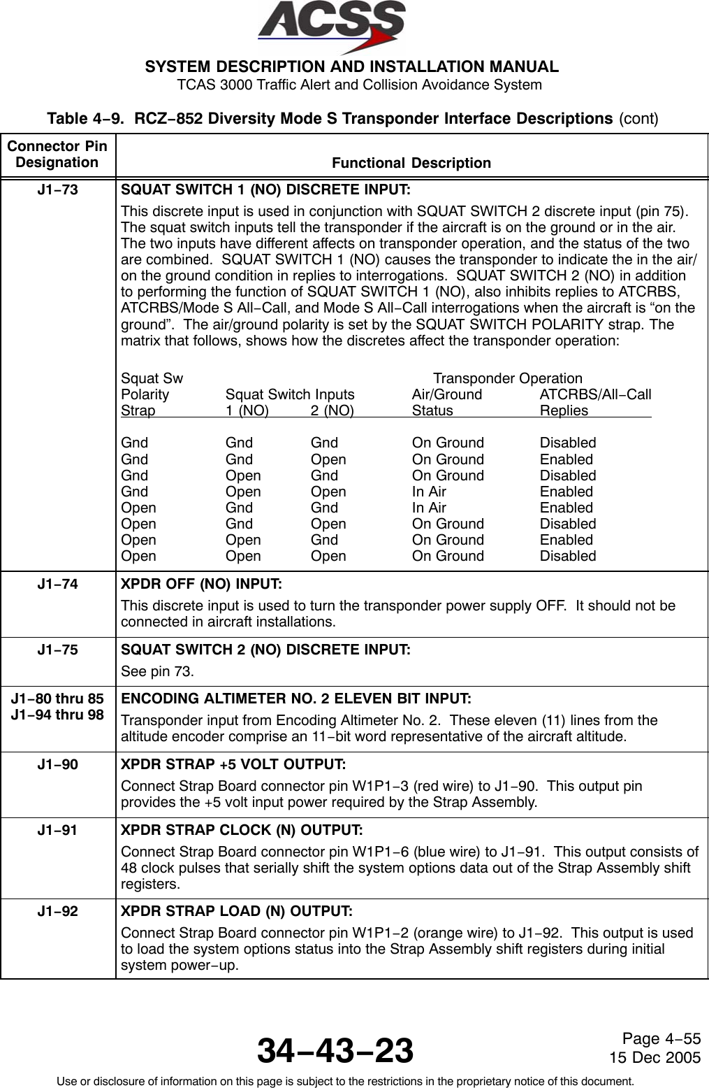
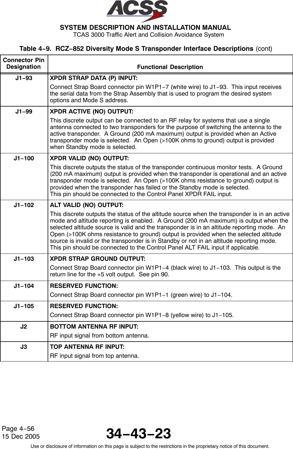
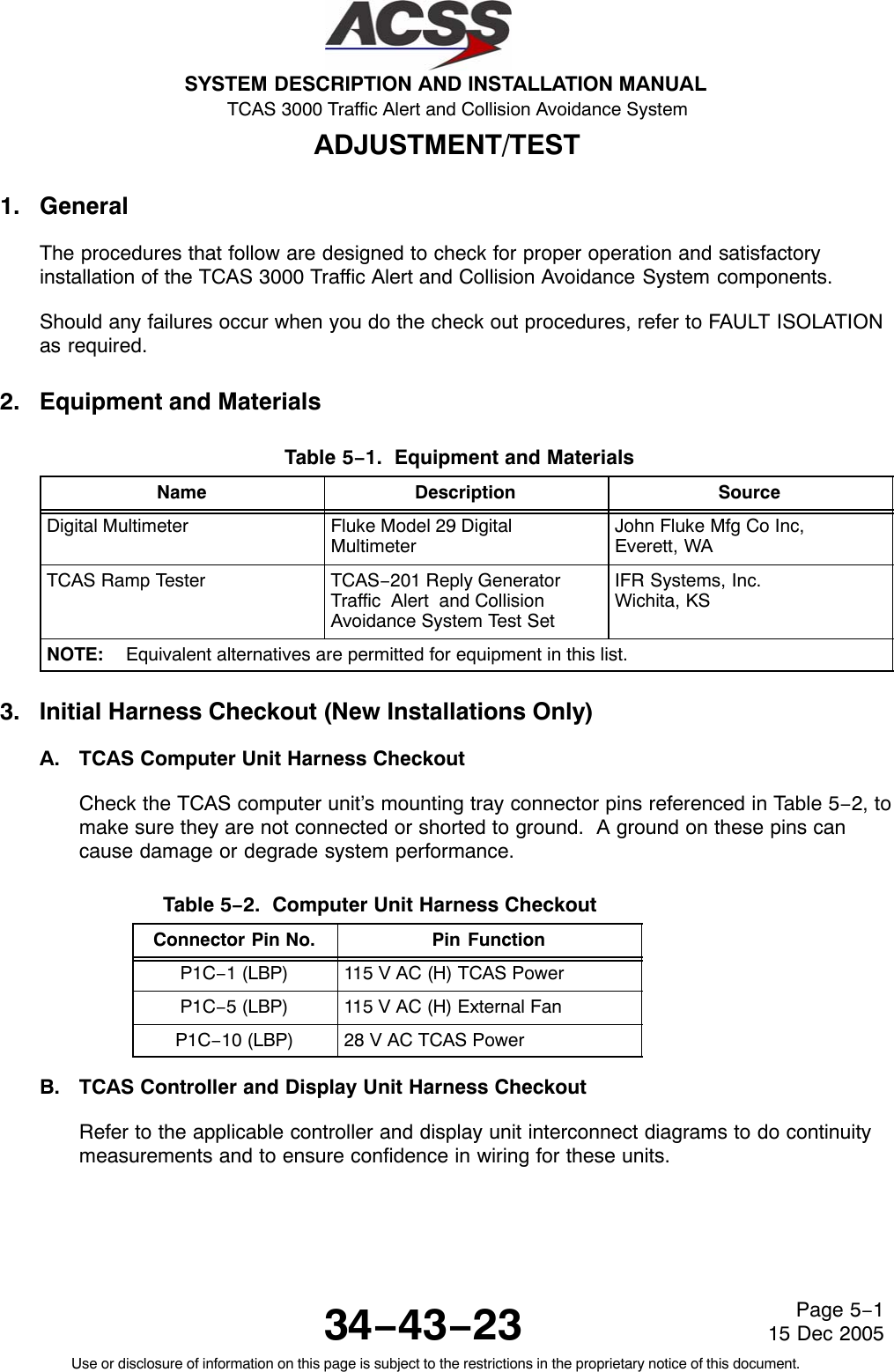
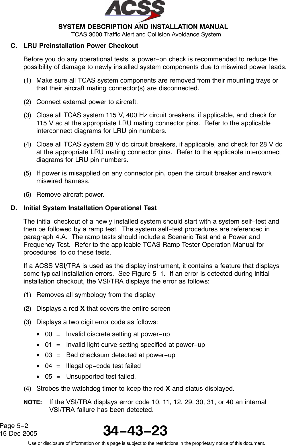
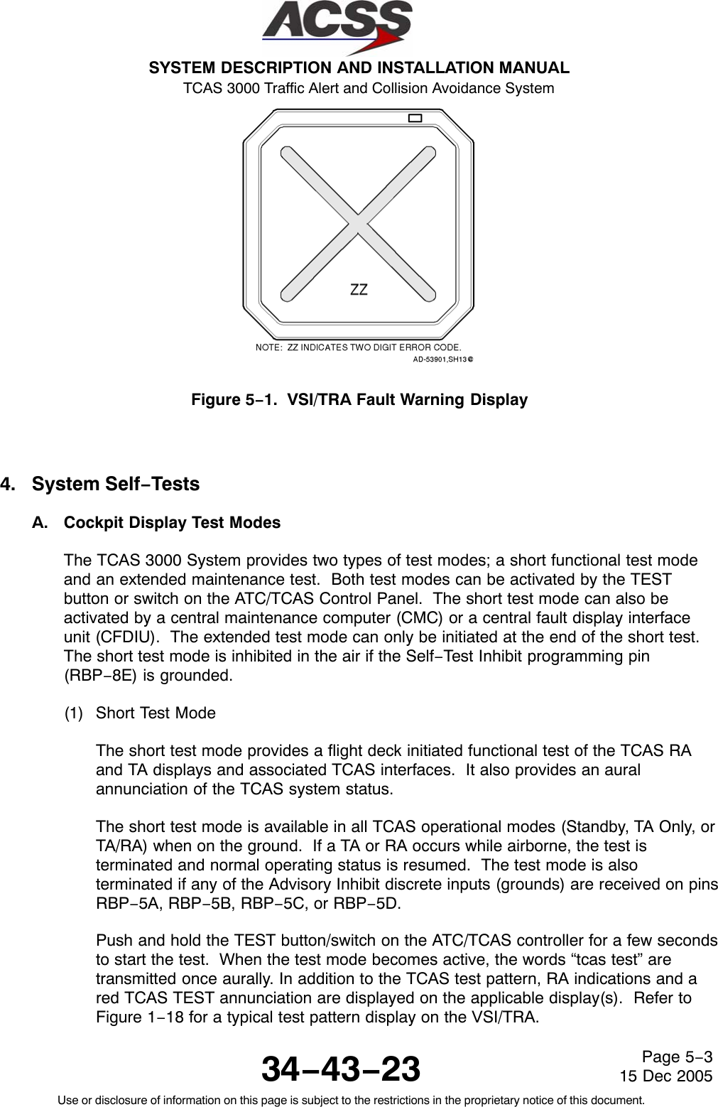
![SYSTEM DESCRIPTION AND INSTALLATION MANUAL TCAS 3000 Traffic Alert and Collision Avoidance System34−43−23Use or disclosure of information on this page is subject to the restrictions in the proprietary notice of this document.Page 5−415 Dec 2005At the completion of the test (8−seconds), the words “tcas test pass” should betransmitted once aurally. In addition, the test pattern is removed from the display(s)and a TCAS PASS annunciation is displayed. If the test fails, the words “tcas testfail” are transmitted once aurally and a TCAS FAIL annunciation is displayed on theapplicable display(s).If the TCAS short test fails, do the TCAS Computer Unit Self−Test proceduresreferenced in paragraph 4.B. to determine which LRU or subsystem is not functioningproperly. To troubleshoot the system, refer to the procedures in the FAULTISOLATION section.(2) Extended Test ModeThe extended test mode provides a flight deck initiated test that displays variouspages of text information that is selected by the ATC Mode S control panel 4096code switches. This test mode is accessible only when on the ground and cannot beinitiated while airborne.The extended test mode is used for maintenance purposes only. It displays variouspages of text information containing the TCAS software part number, fault messages,status of program pins, analog and digital inputs, and other aircraft parameters.To start the test, push and hold the TEST button/switch on the ATC/TCAS controllerfor a minimum of 9 seconds. In addition the conditions that follow must occur:•TCAS is in Standby•The selected transponder is in Standby•Aircraft is on the ground (The AIR/GND discrete [RMP−5K] is grounded)•Landing gear is extended (Landing Gear discrete [RMP−13F] is grounded).Once the extended test mode is established, the 4096 code switches on theATC/TCAS controller are used to select the desired maintenance page for display.Table 5−3 lists the extended mode page names and numbers and the corresponding4096 Ident Code number.](https://usermanual.wiki/ACSS-an-L-3-Communications-and-Thales/T3K-4M/User-Guide-718711-Page-229.png)
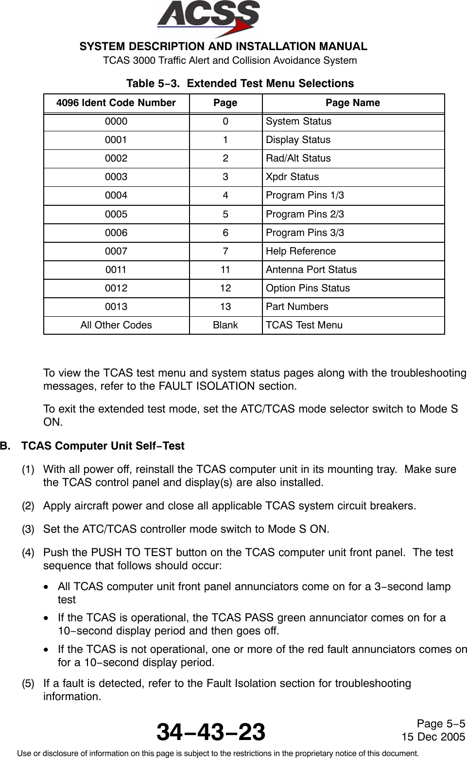
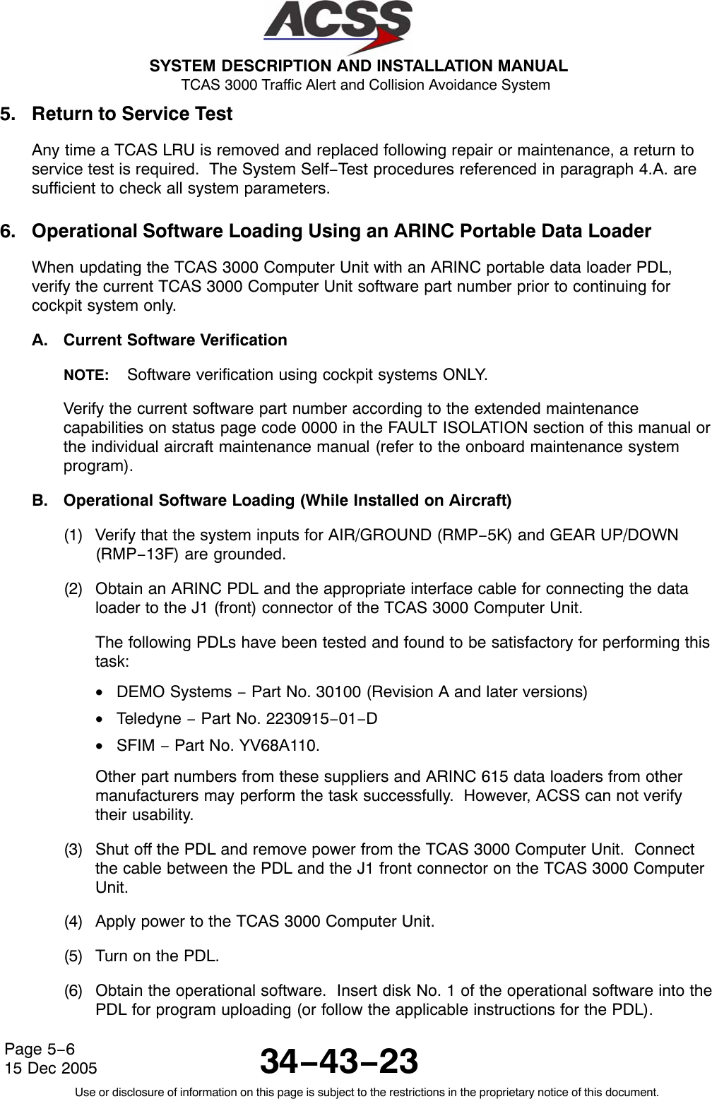
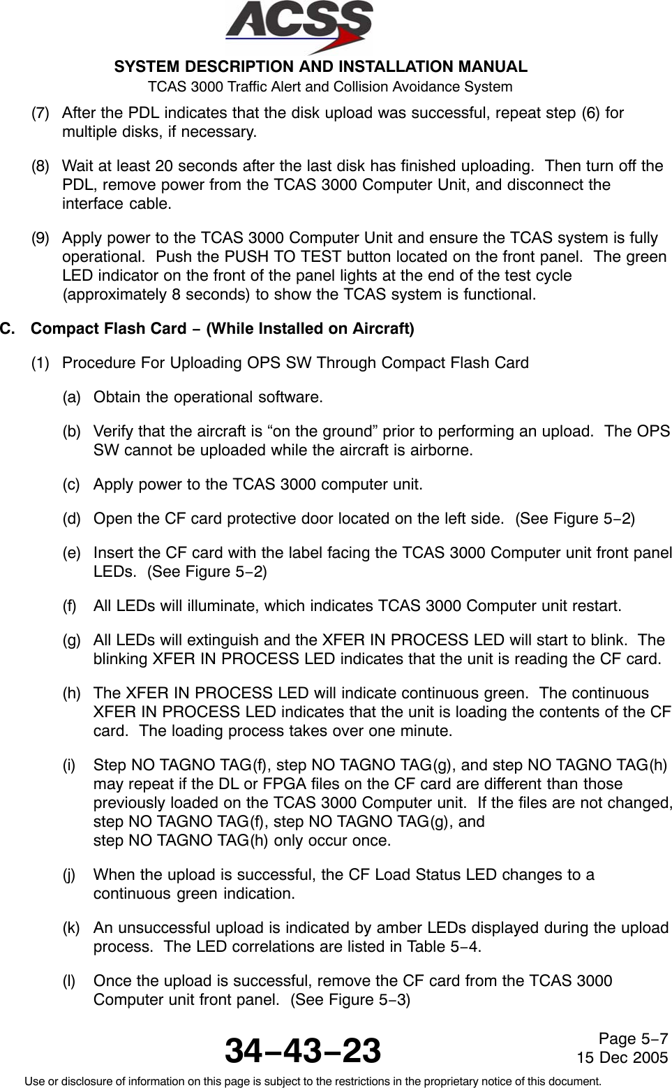
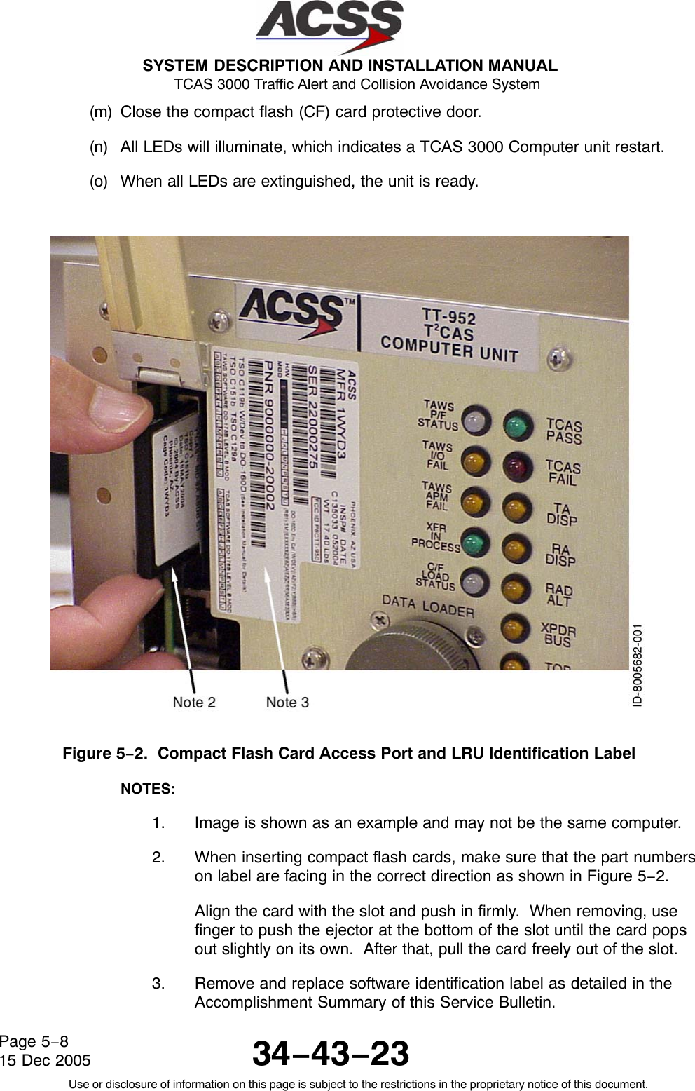
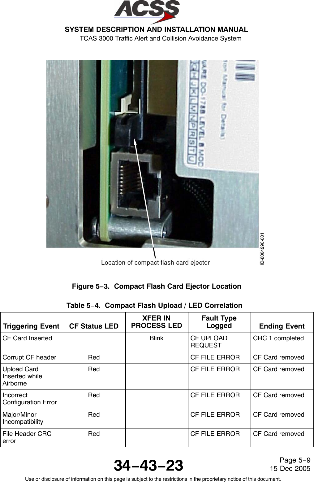
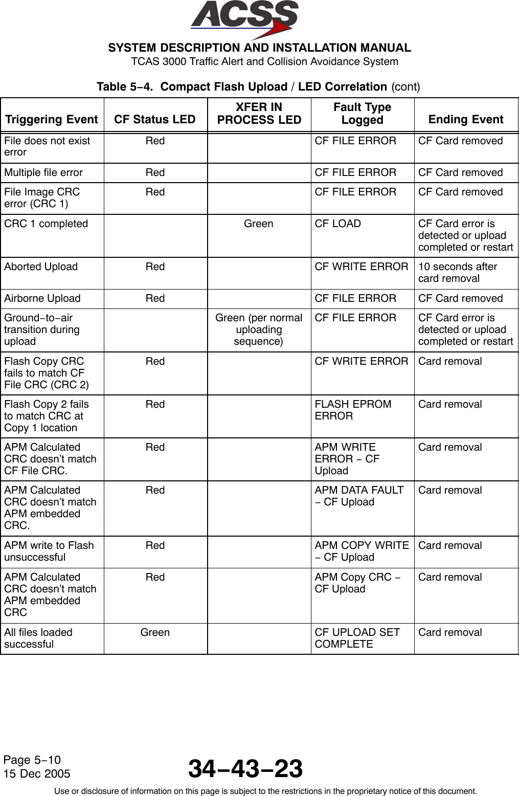
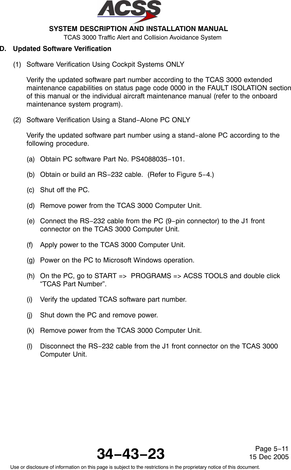
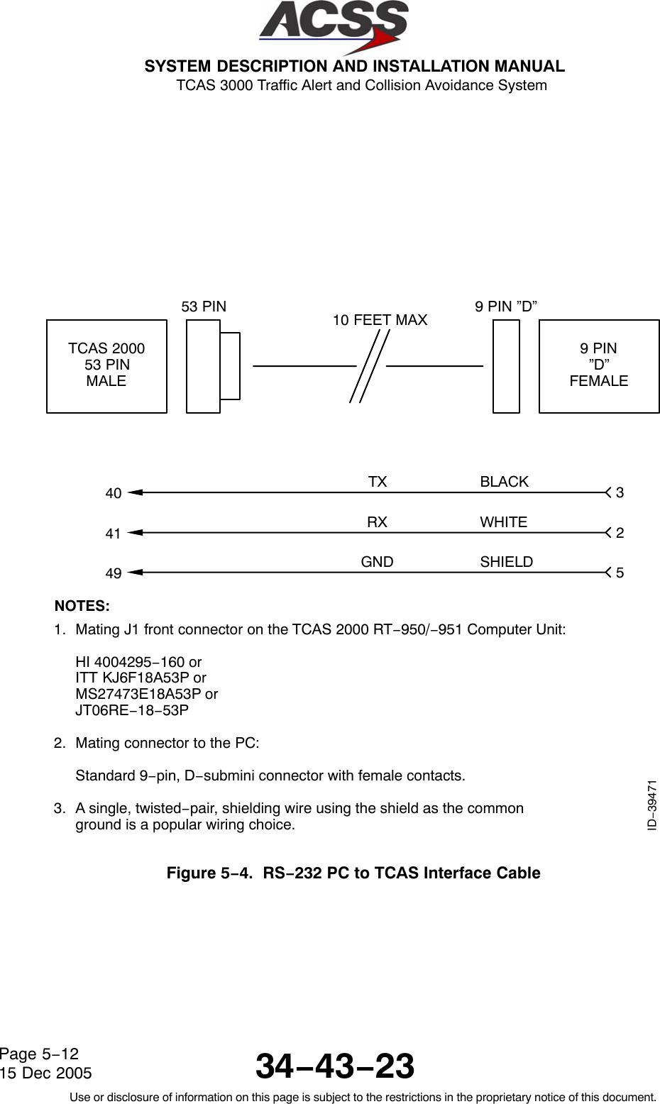
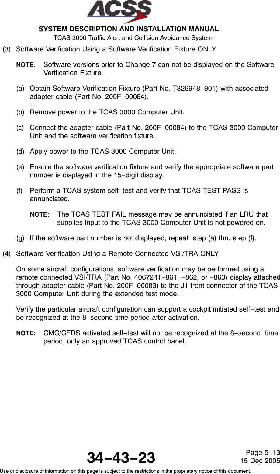

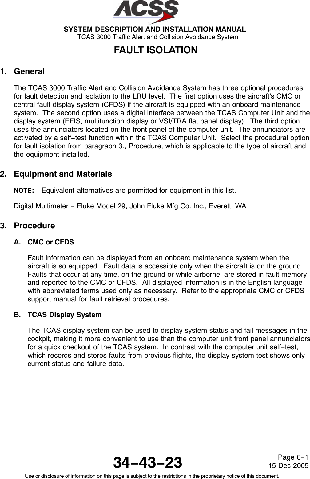
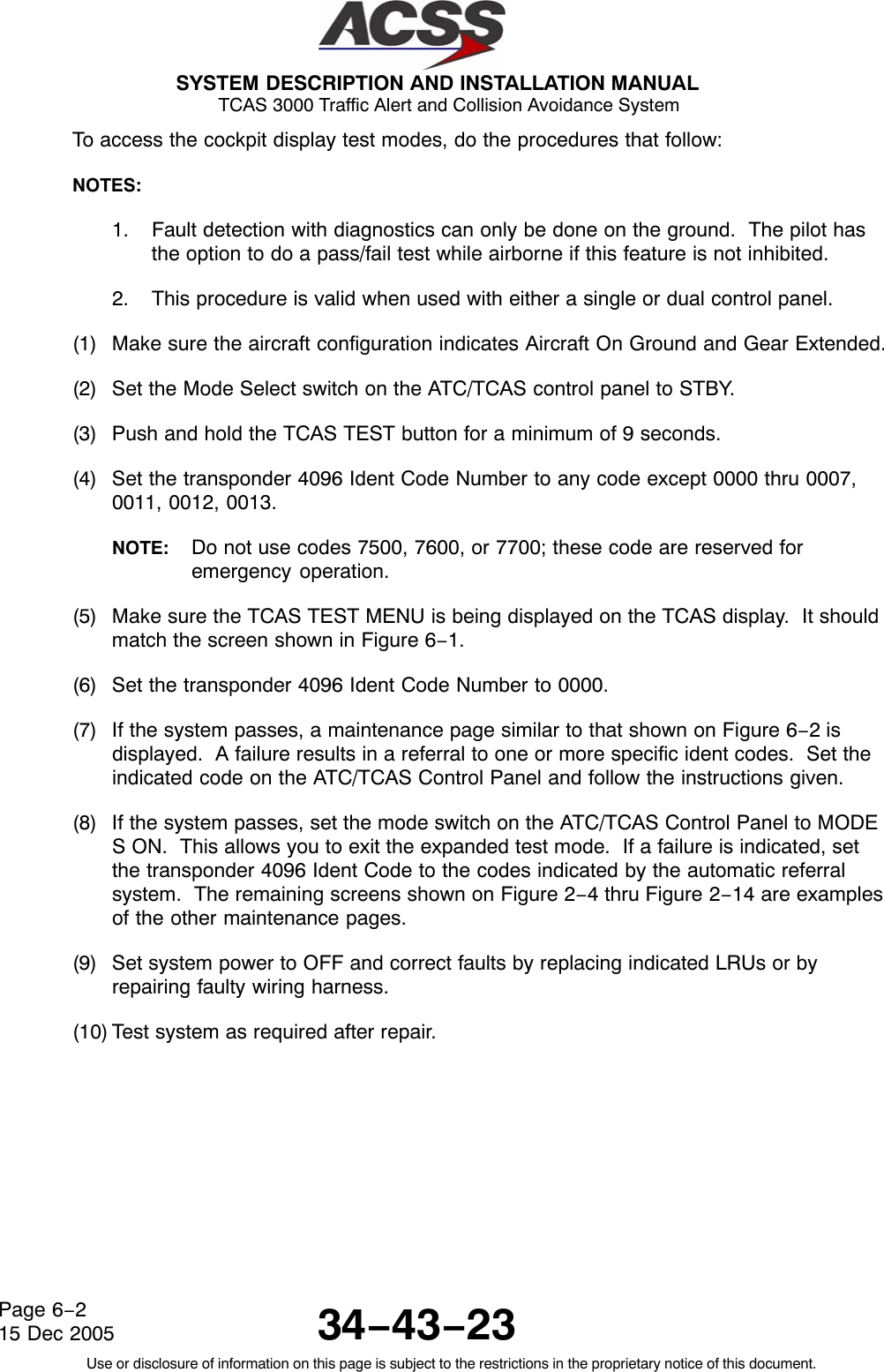
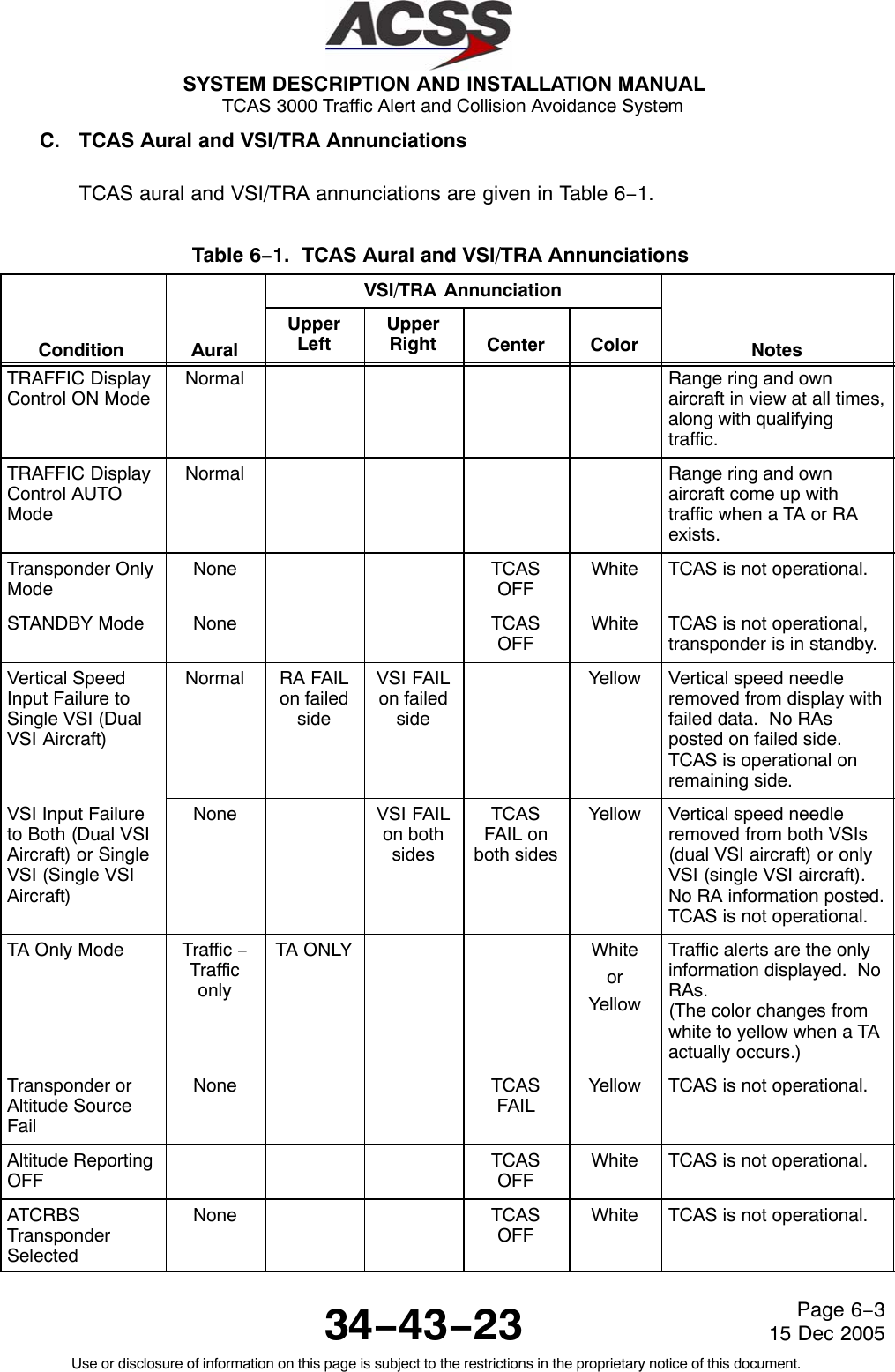
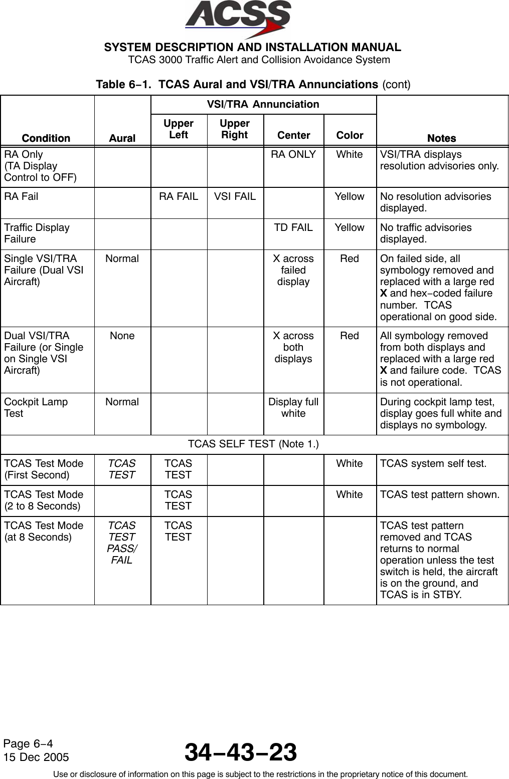
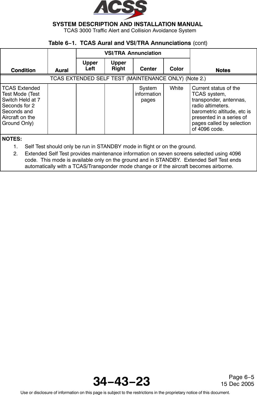
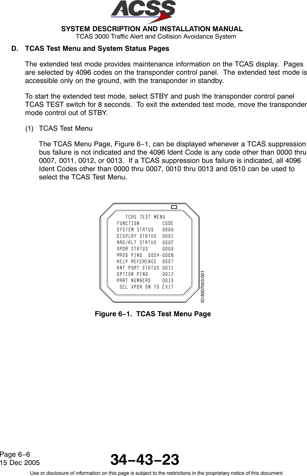
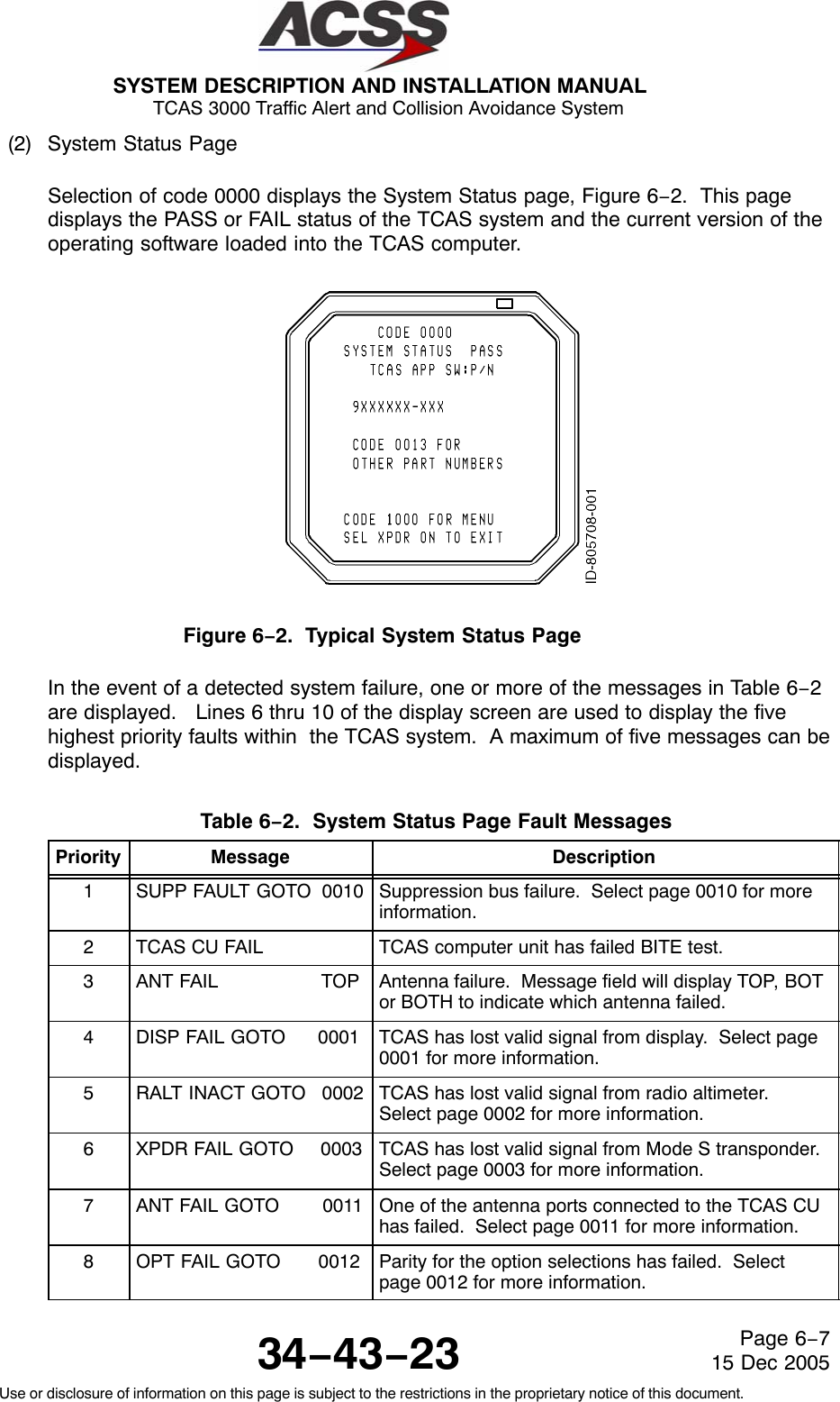
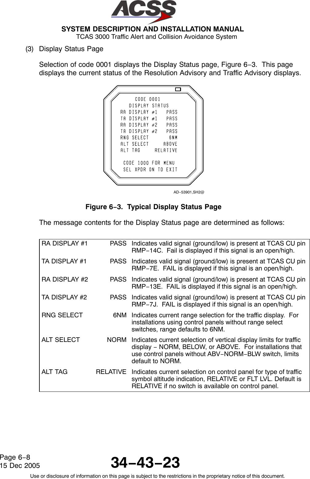
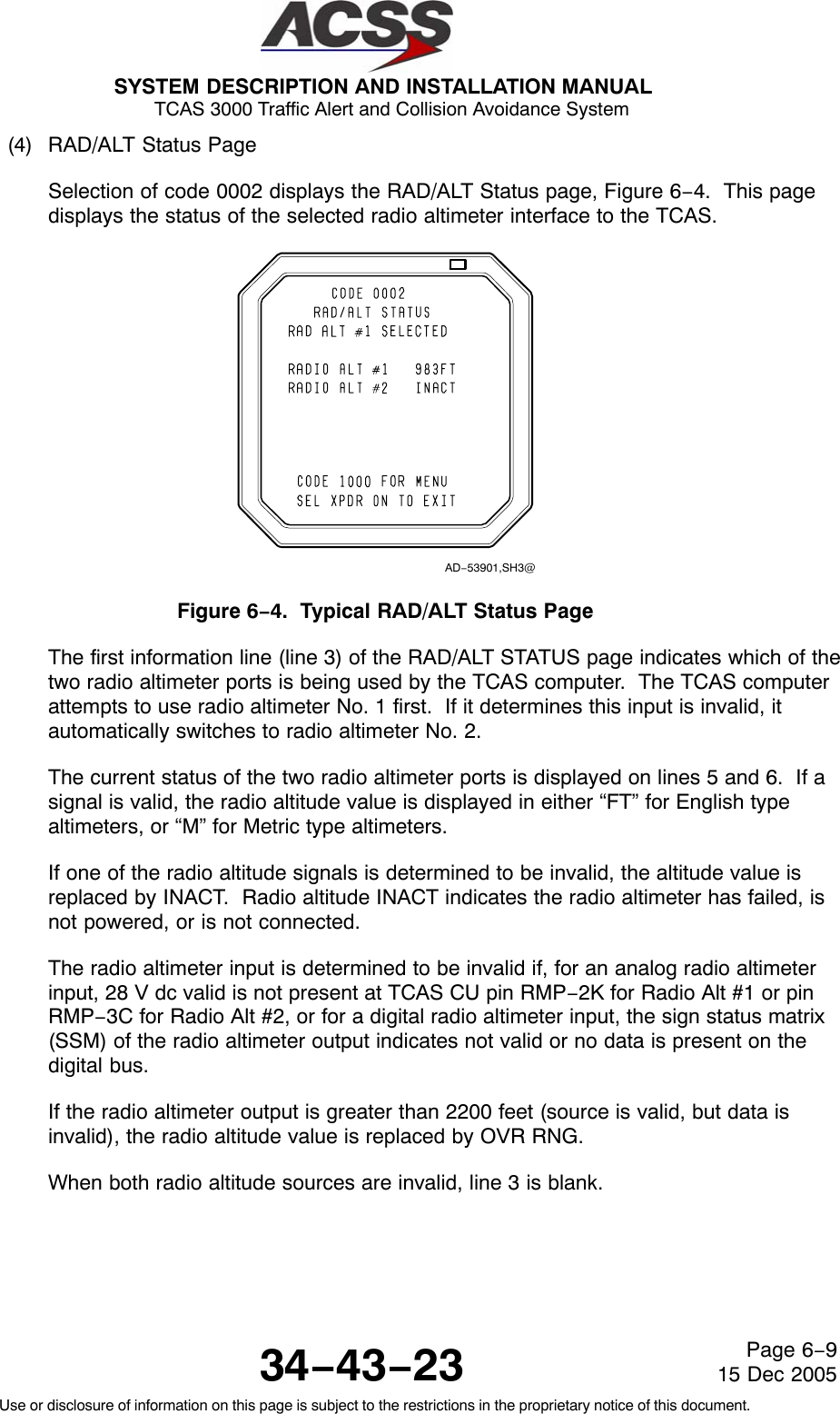
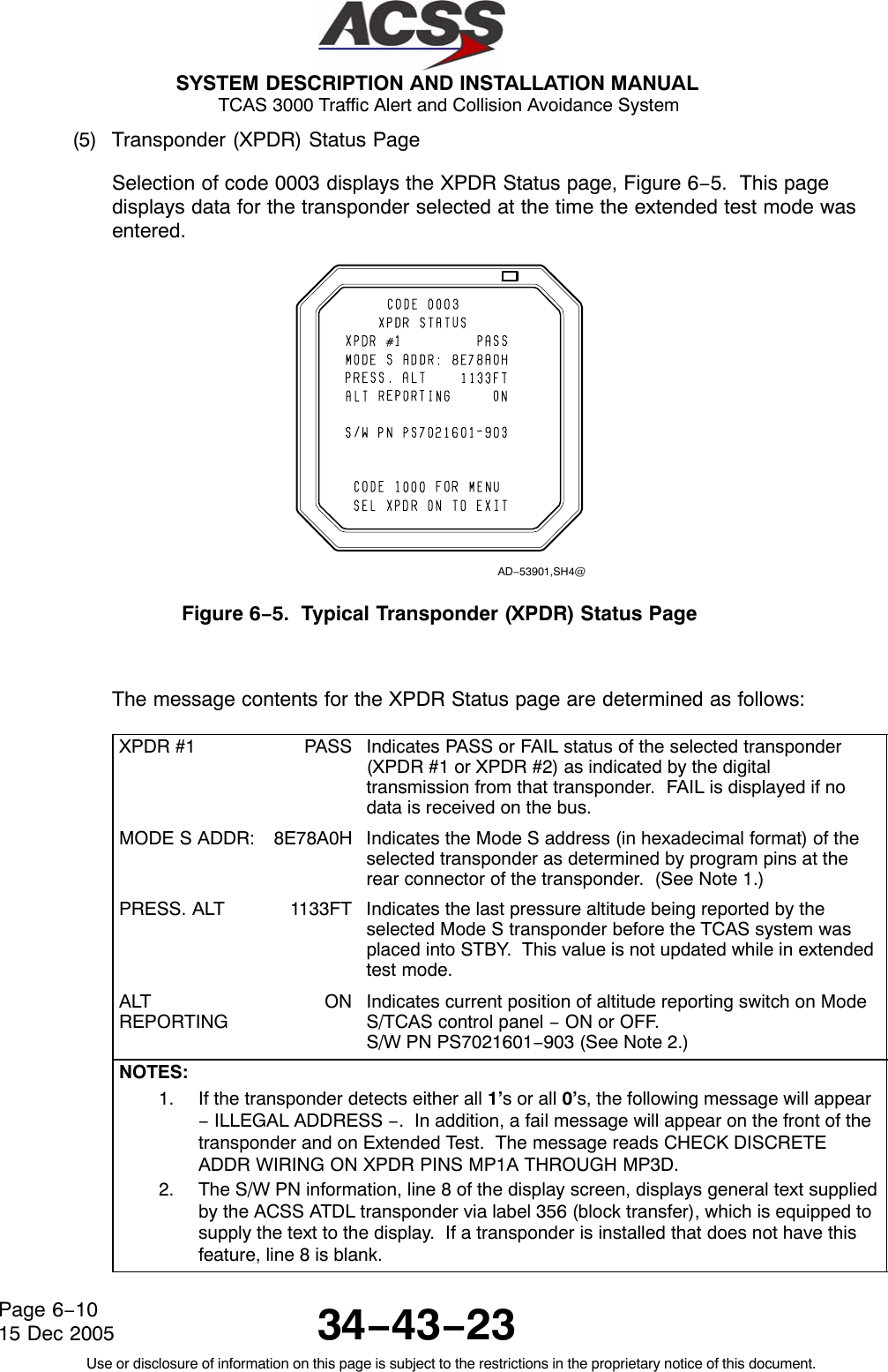
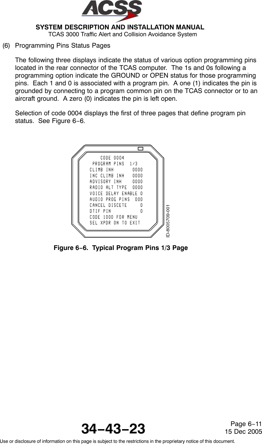
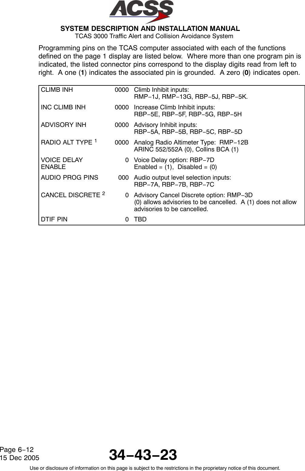
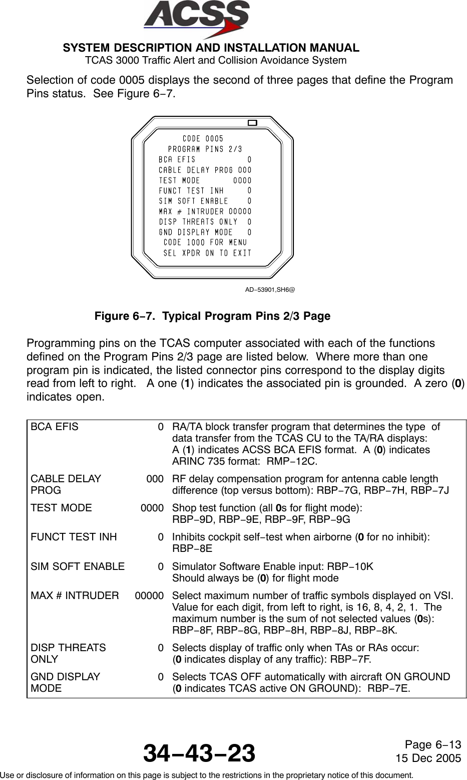
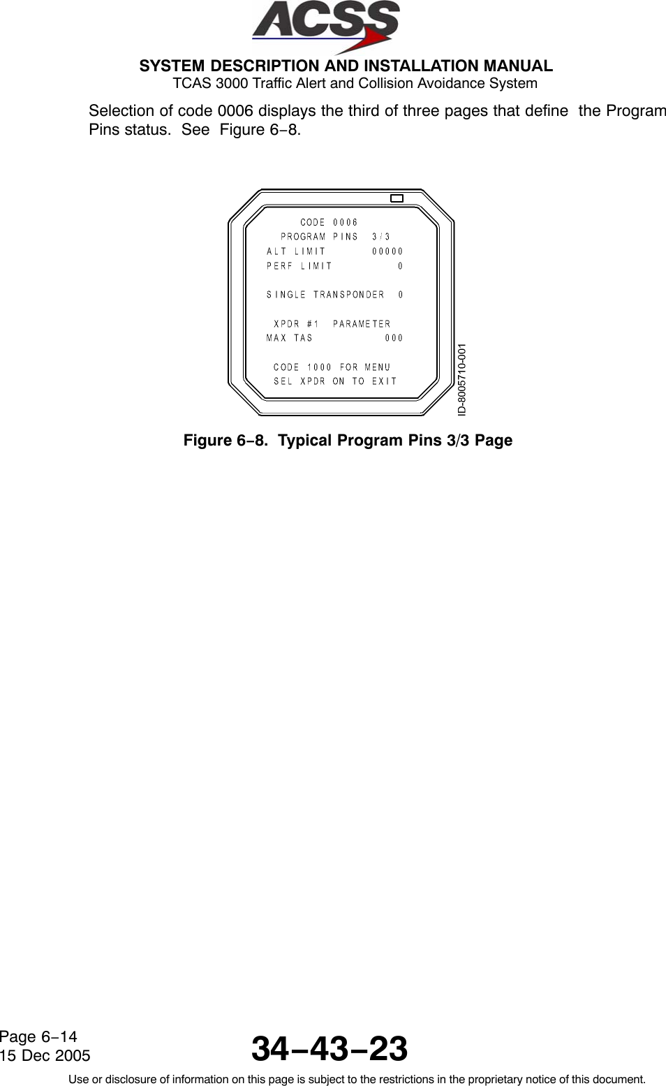
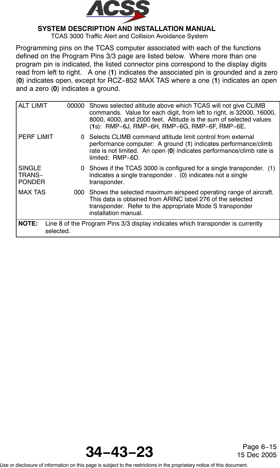
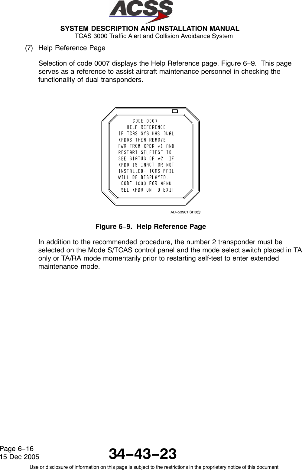
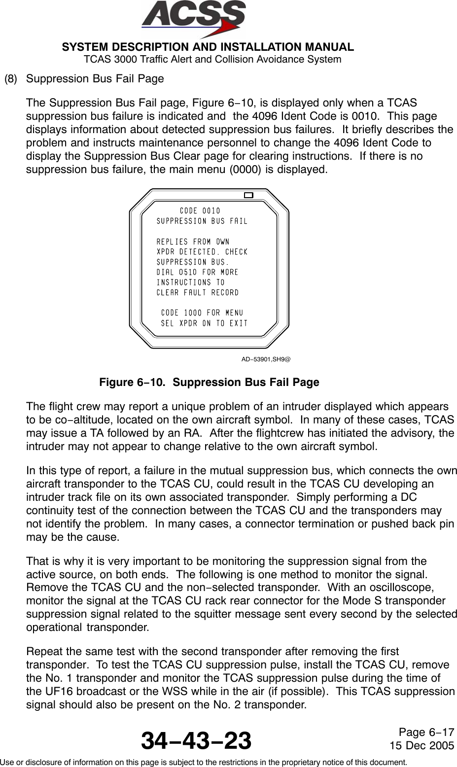
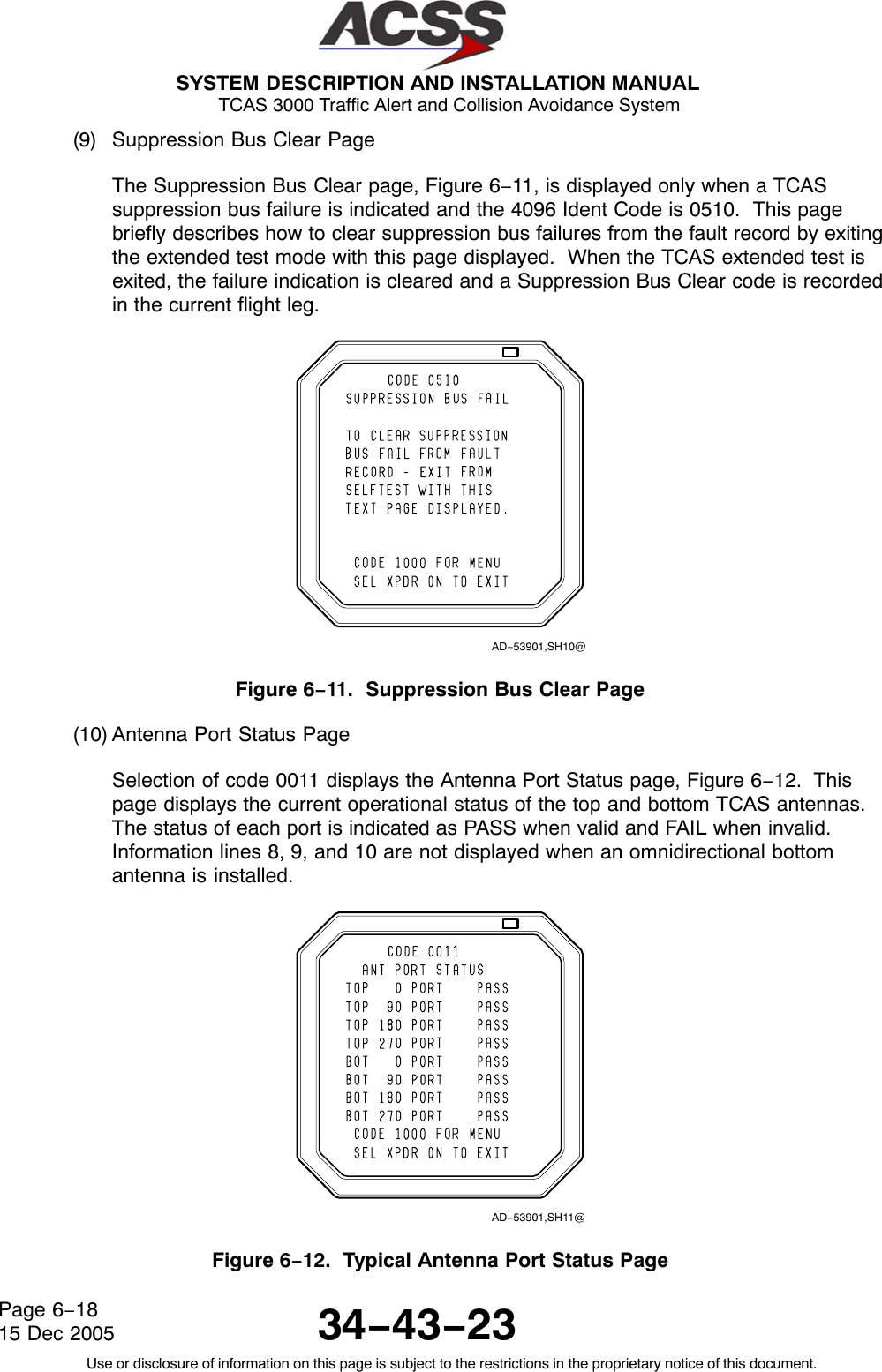
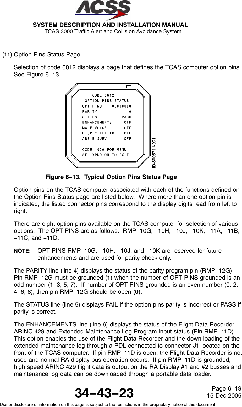
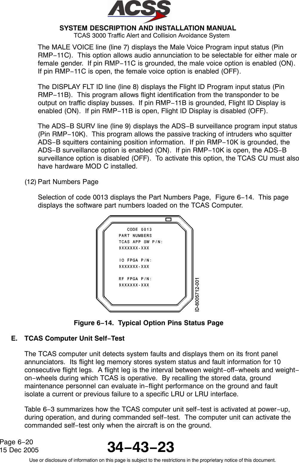
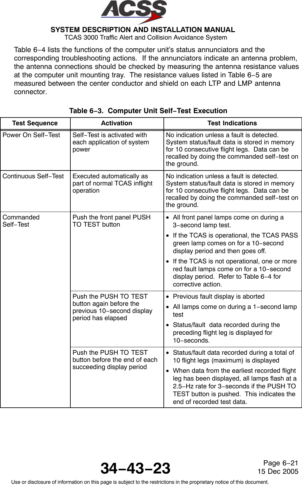
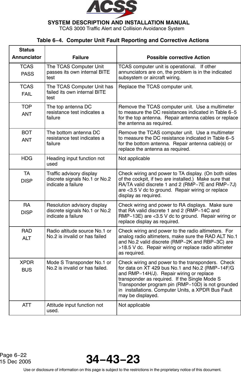
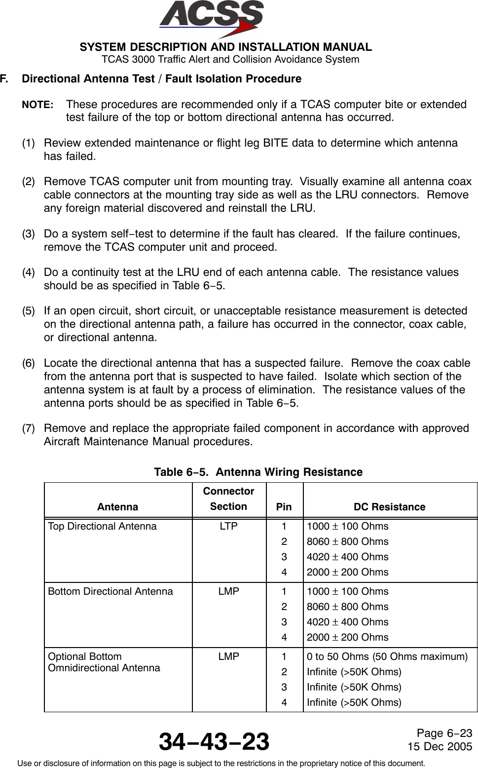
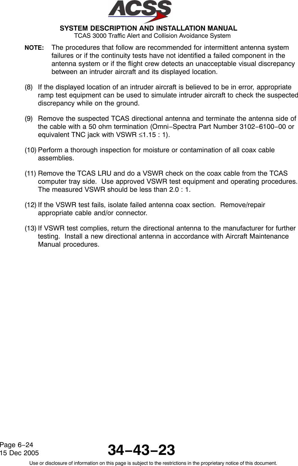

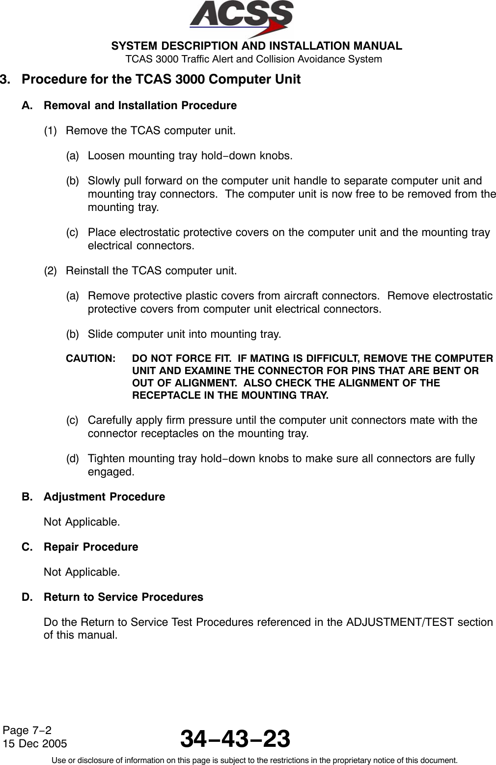
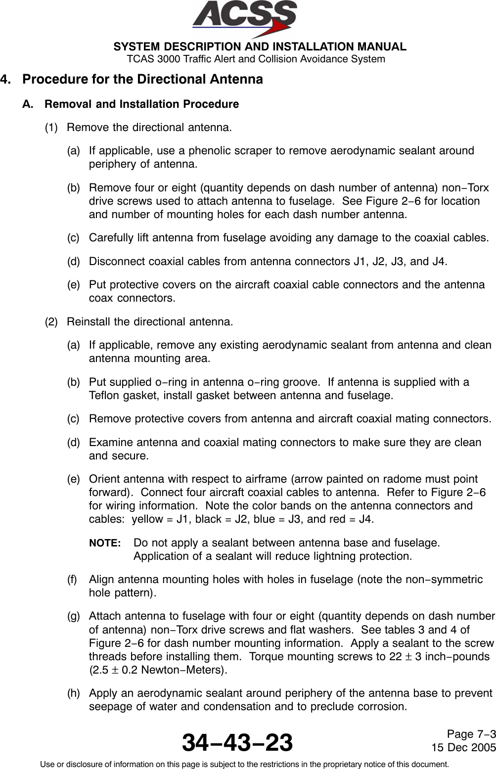
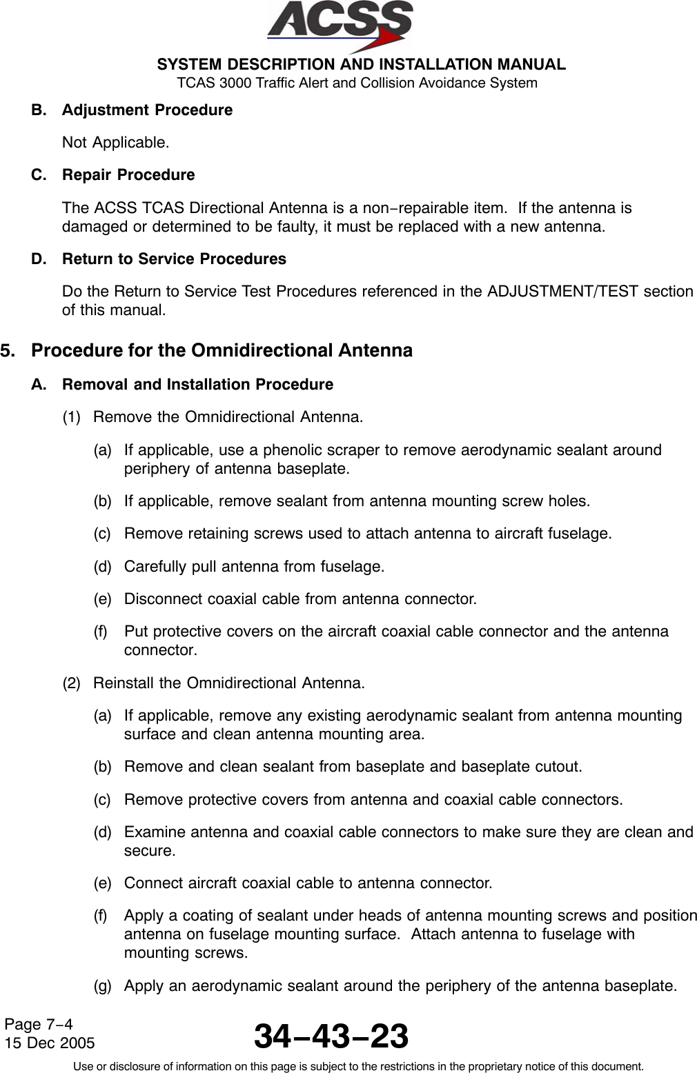
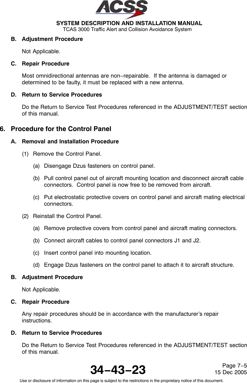
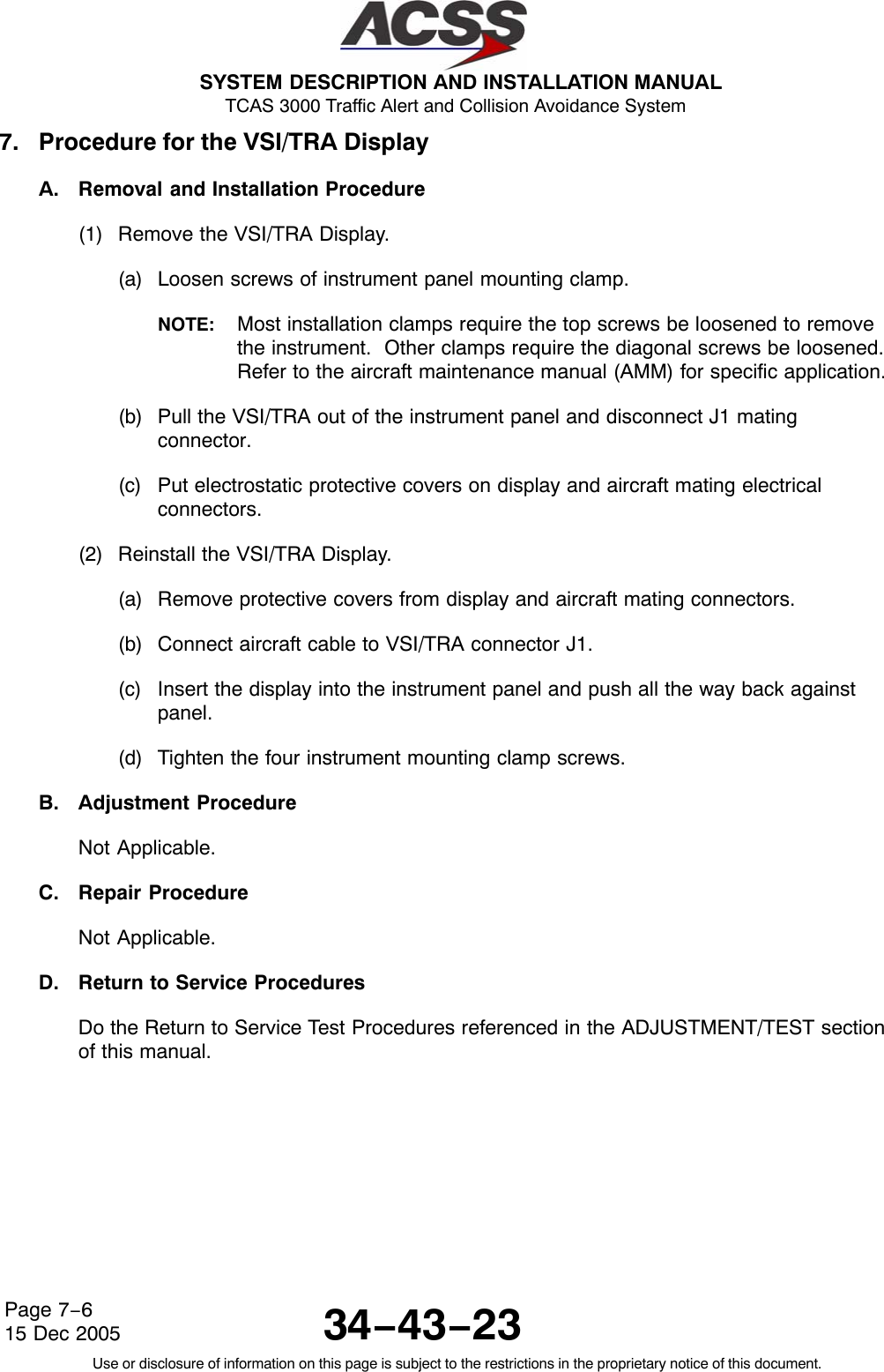

![SYSTEM DESCRIPTION AND INSTALLATION MANUAL TCAS 3000 Traffic Alert and Collision Avoidance System34−43−23Use or disclosure of information on this page is subject to the restrictions in the proprietary notice of this document.Page 7−1015 Dec 200510. Instructions for Continued Airworthiness, FAR Part 25.1529Maintenance requirements and instructions for Continued Airworthiness of the TCAS 3000Traffic Alert and Collision Avoidance System components are contained in the paragraphs thatfollow:Installation of the TCAS 3000 on an aircraft by Supplemental Type Certificate or Form 337obligates the aircraft operator to include the maintenance information provided by this manualin the operator’s AMMl and the operator’s Aircraft Scheduled Maintenance Program.A. Maintenance information for the TCAS 3000 (system description, removal, installation,testing, etc.) is contained in this manual.B. LRU part numbers and other necessary part numbers contained in this manual should beplaced into the aircraft operator’s appropriate aircraft illustrated parts catalog (IPC).C. Wiring diagram information contained in this manual should be placed into the aircraftoperator’s appropriate aircraft Wiring Diagram Manuals.D. The TCAS 3000 components are considered on−condition units and no additionalmaintenance is required other than a check for security and operation at normalinspection intervals.E. If a system component is inoperative, remove unit, secure cables and wiring, collarapplicable switches and circuit breakers, and placard them inoperative. Reviseequipment list and weight and balance as applicable prior to flight and make a log bookentry that unit was removed (refer to FAR Part 91.213 or the aircraft’s MinimumEquipment List [MEL]).F. The TCAS 3000 components can be repaired only at a factory authorized repair center oran appropriately rated FAA Part 145 repair station.G. Once repaired, reinstall the LRU in the aircraft in accordance with the original Form 337approved data or instructions in this manual. Do a Return to Service test of the systemand approve it for return to service with a log book entry in accordance with therequirements specified in FAR Part 43.9.](https://usermanual.wiki/ACSS-an-L-3-Communications-and-Thales/T3K-4M/User-Guide-718711-Page-273.png)