ACSS an L 3 Communications and Thales T3K-6M TCAS II User Manual a
ACSS an L-3 Communications and Thales Company TCAS II a
User Manual

Aviation Communication and Survelliance Systems
19810 North 7th Avenue
Phoenix, Arizona 85027−4400
U.S.A.
15 DECEMBER 2005
34−43−23
TITLE PAGE T-1
PRINTED IN U.S.A. PUB. NO. 8003529−001REVISION −
TCAS 3000
Traffic Alert and Collision Avoidance
System
System Description and
Installation Manual

SYSTEM DESCRIPTION AND INSTALLATION MANUAL
TCAS 3000 Traffic Alert and Collision Avoidance System
Copyright 2005 ACSS
All Rights Reserved
TITLE PAGE T-2
15 DECEMBER 2005
34−43−23
PROPRIETARY NOTICE
This document and the information disclosed herein are proprietary data of ACSS. Neither this
document nor the information contained herein shall be used, reproduced, or disclosed to others
without the written authorization of ACSS, except to the extent required for installation or
maintenance of the recipient’s equipment.
NOTICE − FREEDOM OF INFORMATION ACT (5 USC 552) AND DISCLOSURE OF
CONFIDENTIAL INFORMATION GENERALLY (18 USC 1905)
This document is being furnished in confidence by ACSS. The information disclosed herein falls
within exemption (b) (4) of 5 USC 552 and the prohibitions of 18 USC 1905.
S2005
ACSS is a U.S. registered trademark.
All other marks are owned by their respective companies.

SYSTEM DESCRIPTION AND INSTALLATION MANUAL
TCAS 3000 Traffic Alert and Collision Avoidance System
34−43−23
Use or disclosure of information on this page is subject to the restrictions in the proprietary notice of this document.
Page RR−1
15 Dec 2005
RECORD OF REVISIONS
For each revision, put the revised pages in your manual and discard the superseded pages. Write
the revision number and date, date put in manual, and the incorporator’s initials in the applicable
columns on the Record of Revisions. The initial A shows ACSS is the incorporator.
Revision
Number Revision Date Date Put in Manual By

SYSTEM DESCRIPTION AND INSTALLATION MANUAL
TCAS 3000 Traffic Alert and Collision Avoidance System
34−43−23
Use or disclosure of information on this page is subject to the restrictions in the proprietary notice of this document.
Page RR−2
15 Dec 2005
Blank Page

SYSTEM DESCRIPTION AND INSTALLATION MANUAL
TCAS 3000 Traffic Alert and Collision Avoidance System
34−43−23
Use or disclosure of information on this page is subject to the restrictions in the proprietary notice of this document.
Page RTR−1
15 Dec 2005
RECORD OF TEMPORARY REVISIONS
Read the location instructions on each temporary revision page to know where to put the pages in
your manual. Remove temporary revision pages only when discard instructions are given. For
each temporary revision, give the correct data in the applicable columns.
Temporary
Revision No.
Temporary
Revision Date
Date Put
in Manual By *
Date Removed
from Manual By *
* The initial A in this column shows ACSS has done the task.

SYSTEM DESCRIPTION AND INSTALLATION MANUAL
TCAS 3000 Traffic Alert and Collision Avoidance System
34−43−23
Use or disclosure of information on this page is subject to the restrictions in the proprietary notice of this document.
Page RTR−2
15 Dec 2005
Blank Page

SYSTEM DESCRIPTION AND INSTALLATION MANUAL
TCAS 3000 Traffic Alert and Collision Avoidance System
34−43−23
Use or disclosure of information on this page is subject to the restrictions in the proprietary notice of this document.
Page SBL−1/(Page SBL−2 blank)
15 Dec 2005
SERVICE BULLETIN LIST
Service Bulletin
Identified
Mod
Date Included
in this Manual Description

SYSTEM DESCRIPTION AND INSTALLATION MANUAL
TCAS 3000 Traffic Alert and Collision Avoidance System
34−43−23
Use or disclosure of information on this page is subject to the restrictions in the proprietary notice of this document.
Page LEP−1
15 Dec 2005
LIST OF EFFECTIVE PAGES
Original −. . 15 Dec 2005
Subheading and Page RevisionSubheading and Page Revision Subheading and Page Revision
Title
T−1−
T−2−
Record of Revisions
RR−1−
RR−2−
Record of Temporary Revisions
RTR−1−
RTR−2−
Service Bulletin List
SBL−1−
SBL−2−
List of Effective Pages
LEP−1−
LEP−2−
LEP−3−
LEP−4−
Table of Contents
TC−1−
TC−2−
TC−3−
TC−4−
TC−5−
TC−6−
TC−7−
TC−8−
TC−9−
TC−10 −
Introduction
INTRO−1−
INTRO−2−
INTRO−3−
INTRO−4−
INTRO−5−
INTRO−6−
System Description
1−1−
1−2−
1−3−
1−4−
1−5−
1−6−
1−7−
1−8−
1−9−
1−10 −
1−11 −
1−12 −
1−13 −
1−14 −
F 1−15/1−16 −
1−17 −
1−18 −
1−19 −
1−20 −
1−21 −
1−22 −
1−23 −
1−24 −
1−25 −
1−26 −
1−27 −
1−28 −
Hindicates changed, added, or deleted page.
F indicates right foldout page with blank back.

SYSTEM DESCRIPTION AND INSTALLATION MANUAL
TCAS 3000 Traffic Alert and Collision Avoidance System
34−43−23
Use or disclosure of information on this page is subject to the restrictions in the proprietary notice of this document.
Page LEP−2
15 Dec 2005
1−29 −
1−30 −
1−31 −
1−32 −
1−33 −
1−34 −
1−35 −
1−36 −
1−37 −
1−38 −
1−39 −
1−40 −
1−41 −
1−42 −
1−43 −
1−44 −
1−45 −
1−46 −
1−47 −
1−48 −
1−49 −
1−50 −
1−51 −
1−52 −
1−53 −
1−54 −
1−55 −
1−56 −
1−57 −
1−58 −
1−59 −
1−60 −
1−61 −
1−62 −
1−63 −
1−64 −
Mechanical Installation
2−1−
2−2−
2−3−
2−4−
2−5−
2−6−
F 2−7/2−8−
F 2−9/2−10 −
F 2−11/2−12 −
F 2−13/2−14 −
F 2−15/2−16 −
F 2−17/2−18 −
2−19 −
2−20 −
F 2−21/2−22 −
F 2−23/2−24 −
F 2−25/2−26 −
F 2−27/2−28 −
F 2−29/2−30 −
F 2−31/2−32 −
F 2−33/2−34 −
F 2−35/2−36 −
F 2−37/2−38 −
F 2−39/2−40 −
F 2−41/2−42 −
F 2−43/2−44 −
F 2−45/2−46 −
F 2−47/2−48 −
F 2−49/2−50 −
F 2−51/2−52 −
F 2−53/2−54 −
F 2−55/2−56 −
Electrical Installation
3−1−
3−2−
F 3−3/3−4−
F 3−5/3−6−
F 3−7/3−8−
F 3−9/3−10 −
F 3−11/3−12 −
F 3−13/3−14 −
F 3−15/3−16 −
3−17 −
3−18 −
3−19 −
3−20 −
3−21 −
Subheading and Page RevisionSubheading and Page Revision Subheading and Page Revision

SYSTEM DESCRIPTION AND INSTALLATION MANUAL
TCAS 3000 Traffic Alert and Collision Avoidance System
34−43−23
Use or disclosure of information on this page is subject to the restrictions in the proprietary notice of this document.
Page LEP−3
15 Dec 2005
3−22 −
3−23 −
3−24 −
3−25 −
3−26 −
3−27 −
3−28 −
3−29 −
3−30 −
3−31 −
3−32 −
3−33 −
3−34 −
3−35 −
3−36 −
3−37 −
3−38 −
3−39 −
3−40 −
3−41 −
3−42 −
3−43 −
3−44 −
3−45 −
3−46 −
3−47 −
3−48 −
3−49 −
3−50 −
3−51 −
3−52 −
3−53 −
3−54 −
3−55 −
3−56 −
3−57 −
3−58 −
Loading/Gradient Specifications
4−1−
4−2−
4−3−
4−4−
4−5−
4−6−
4−7−
4−8−
4−9−
4−10 −
4−11 −
4−12 −
4−13 −
4−14 −
4−15 −
4−16 −
4−17 −
4−18 −
4−19 −
4−20 −
4−21 −
4−22 −
4−23 −
4−24 −
4−25 −
4−26 −
4−27 −
4−28 −
4−29 −
4−30 −
4−31 −
4−32 −
4−33 −
4−34 −
4−35 −
4−36 −
4−37 −
4−38 −
4−39 −
4−40 −
4−41 −
4−42 −
4−43 −
4−44 −
4−45 −
4−46 −
4−47 −
Subheading and Page RevisionSubheading and Page Revision Subheading and Page Revision

SYSTEM DESCRIPTION AND INSTALLATION MANUAL
TCAS 3000 Traffic Alert and Collision Avoidance System
34−43−23
Use or disclosure of information on this page is subject to the restrictions in the proprietary notice of this document.
Page LEP−4
15 Dec 2005
4−48 −
4−49 −
4−50 −
4−51 −
4−52 −
4−53 −
4−54 −
4−55 −
4−56 −
Adjustment/Test
5−1−
5−2−
5−3−
5−4−
5−5−
5−6−
5−7−
5−8−
5−9−
5−10 −
5−11 −
5−12 −
5−13 −
5−14 −
Fault Isolation
6−1−
6−2−
6−3−
6−4−
6−5−
6−6−
6−7−
6−8−
6−9−
6−10 −
6−11 −
6−12 −
6−13 −
6−14 −
6−15 −
6−16 −
6−17 −
6−18 −
6−19 −
6−20 −
6−21 −
6−22 −
6−23 −
6−24 −
Maintenance Practices
7−1−
7−2−
7−3−
7−4−
7−5−
7−6−
7−7−
7−8−
7−9−
7−10 −
7−11 −
7−12 −
Inspection/Check
8−1−
8−2−
Cleaning/Painting
9−1−
9−2−
9−3−
9−4−
9−5−
9−6−
Repairs
10−1−
10−2−
Subheading and Page RevisionSubheading and Page Revision Subheading and Page Revision

SYSTEM DESCRIPTION AND INSTALLATION MANUAL
TCAS 3000 Traffic Alert and Collision Avoidance System
34−43−23
Use or disclosure of information on this page is subject to the restrictions in the proprietary notice of this document.
Page TC−1
15 Dec 2005
TABLE OF CONTENTS
Section Page
INTRODUCTION INTRO−1. . . . . . . . . . . . . . . . . . . . . . . . . . . . . . . . . . . . . . . . . . . . . . . . . . . . . . . . . . . . . .
1. General INTRO−1. . . . . . . . . . . . . . . . . . . . . . . . . . . . . . . . . . . . . . . . . . . . . . . . . . . . . . . . . . . . . . . . . .
2. Reference Documents INTRO−1. . . . . . . . . . . . . . . . . . . . . . . . . . . . . . . . . . . . . . . . . . . . . . . . . . . . .
3. Weights and Measurements INTRO−1. . . . . . . . . . . . . . . . . . . . . . . . . . . . . . . . . . . . . . . . . . . . . . . .
4. Acronyms and Abbreviations INTRO−2. . . . . . . . . . . . . . . . . . . . . . . . . . . . . . . . . . . . . . . . . . . . . . .
5. Special Precautions INTRO−5. . . . . . . . . . . . . . . . . . . . . . . . . . . . . . . . . . . . . . . . . . . . . . . . . . . . . . .
SYSTEM DESCRIPTION 1−1. . . . . . . . . . . . . . . . . . . . . . . . . . . . . . . . . . . . . . . . . . . . . . . . . . . . . .
1. General 1−1. . . . . . . . . . . . . . . . . . . . . . . . . . . . . . . . . . . . . . . . . . . . . . . . . . . . . . . . . . . . . . . . . .
2. System Components 1−1. . . . . . . . . . . . . . . . . . . . . . . . . . . . . . . . . . . . . . . . . . . . . . . . . . . . . .
3. System Description 1−7. . . . . . . . . . . . . . . . . . . . . . . . . . . . . . . . . . . . . . . . . . . . . . . . . . . . . . . .
A. System Functional Description 1−7. . . . . . . . . . . . . . . . . . . . . . . . . . . . . . . . . . . . . . . . . .
B. System Configurations 1−11. . . . . . . . . . . . . . . . . . . . . . . . . . . . . . . . . . . . . . . . . . . . . . . . .
4. Component Descriptions 1−17. . . . . . . . . . . . . . . . . . . . . . . . . . . . . . . . . . . . . . . . . . . . . . . . . . .
A. RT−950/951 TCAS Computer Unit 1−17. . . . . . . . . . . . . . . . . . . . . . . . . . . . . . . . . . . . . . .
(1) System Interfaces 1−21. . . . . . . . . . . . . . . . . . . . . . . . . . . . . . . . . . . . . . . . . . . . . . . . .
(2) Discrete Inputs 1−24. . . . . . . . . . . . . . . . . . . . . . . . . . . . . . . . . . . . . . . . . . . . . . . . . . . .
(3) Program Inputs 1−24. . . . . . . . . . . . . . . . . . . . . . . . . . . . . . . . . . . . . . . . . . . . . . . . . . .
(4) Discrete Outputs 1−24. . . . . . . . . . . . . . . . . . . . . . . . . . . . . . . . . . . . . . . . . . . . . . . . . .
(5) Self−Test Function 1−24. . . . . . . . . . . . . . . . . . . . . . . . . . . . . . . . . . . . . . . . . . . . . . . . .
B. Directional Antenna 1−25. . . . . . . . . . . . . . . . . . . . . . . . . . . . . . . . . . . . . . . . . . . . . . . . . . . .
C. ACSS Mode S/TCAS Control Panels 1−28. . . . . . . . . . . . . . . . . . . . . . . . . . . . . . . . . . . .
(1) Functional Description and Operation 1−29. . . . . . . . . . . . . . . . . . . . . . . . . . . . . . . .
D. Gables ATC/TCAS Dual Mode S Transponder Control Panel 1−30. . . . . . . . . . . . . . . .
(1) Functional Description and Operation 1−32. . . . . . . . . . . . . . . . . . . . . . . . . . . . . . . .
E. VSI/TRA Display 1−34. . . . . . . . . . . . . . . . . . . . . . . . . . . . . . . . . . . . . . . . . . . . . . . . . . . . . .
(1) Functional Description and Operation 1−36. . . . . . . . . . . . . . . . . . . . . . . . . . . . . . . .
(2) Software Considerations 1−37. . . . . . . . . . . . . . . . . . . . . . . . . . . . . . . . . . . . . . . . . . .
(3) Built−In Test Equipment (BITE) and Self−Test Capability 1−37. . . . . . . . . . . . . . .
F. Pressure Transducer Module 1−40. . . . . . . . . . . . . . . . . . . . . . . . . . . . . . . . . . . . . . . . . . .
G. XS−950 Mode S Data Link Transponder 1−42. . . . . . . . . . . . . . . . . . . . . . . . . . . . . . . . .
H. RCZ−852 Diversity Mode S Transponder 1−47. . . . . . . . . . . . . . . . . . . . . . . . . . . . . . . . .

SYSTEM DESCRIPTION AND INSTALLATION MANUAL
TCAS 3000 Traffic Alert and Collision Avoidance System
34−43−23
Use or disclosure of information on this page is subject to the restrictions in the proprietary notice of this document.
Page TC−2
15 Dec 2005
Section Page
5. System Operation 1−51. . . . . . . . . . . . . . . . . . . . . . . . . . . . . . . . . . . . . . . . . . . . . . . . . . . . . . . . .
A. Operational Modes 1−51. . . . . . . . . . . . . . . . . . . . . . . . . . . . . . . . . . . . . . . . . . . . . . . . . . . .
(1) TCAS Modes 1−51. . . . . . . . . . . . . . . . . . . . . . . . . . . . . . . . . . . . . . . . . . . . . . . . . . . . .
(2) Non−TCAS Modes 1−52. . . . . . . . . . . . . . . . . . . . . . . . . . . . . . . . . . . . . . . . . . . . . . . .
(3) Extended Test Mode 1−52. . . . . . . . . . . . . . . . . . . . . . . . . . . . . . . . . . . . . . . . . . . . . . .
B. Display Symbology 1−53. . . . . . . . . . . . . . . . . . . . . . . . . . . . . . . . . . . . . . . . . . . . . . . . . . . .
(1) Colors 1−53. . . . . . . . . . . . . . . . . . . . . . . . . . . . . . . . . . . . . . . . . . . . . . . . . . . . . . . . . . .
(2) Traffic Identification 1−54. . . . . . . . . . . . . . . . . . . . . . . . . . . . . . . . . . . . . . . . . . . . . . . .
(3) Data Tags 1−54. . . . . . . . . . . . . . . . . . . . . . . . . . . . . . . . . . . . . . . . . . . . . . . . . . . . . . . .
(4) VSI Scale Overlays 1−55. . . . . . . . . . . . . . . . . . . . . . . . . . . . . . . . . . . . . . . . . . . . . . . .
(5) Reference Graphics and Annunciations 1−55. . . . . . . . . . . . . . . . . . . . . . . . . . . . . .
C. Aural Messages 1−55. . . . . . . . . . . . . . . . . . . . . . . . . . . . . . . . . . . . . . . . . . . . . . . . . . . . . . .
(1) Requirements and Limitations 1−55. . . . . . . . . . . . . . . . . . . . . . . . . . . . . . . . . . . . . . .
(2) Traffic Advisory (TA) Message 1−56. . . . . . . . . . . . . . . . . . . . . . . . . . . . . . . . . . . . . . .
(3) Resolution Advisory (RA) Messages 1−56. . . . . . . . . . . . . . . . . . . . . . . . . . . . . . . . .
(4) Enhanced RA Messages 1−57. . . . . . . . . . . . . . . . . . . . . . . . . . . . . . . . . . . . . . . . . . .
D. Operating Procedures 1−58. . . . . . . . . . . . . . . . . . . . . . . . . . . . . . . . . . . . . . . . . . . . . . . . .
(1) Pre−Flight Test 1−58. . . . . . . . . . . . . . . . . . . . . . . . . . . . . . . . . . . . . . . . . . . . . . . . . . . .
(2) TCAS Mode Activation 1−59. . . . . . . . . . . . . . . . . . . . . . . . . . . . . . . . . . . . . . . . . . . . .
(3) TCAS Mode Deactivation 1−59. . . . . . . . . . . . . . . . . . . . . . . . . . . . . . . . . . . . . . . . . . .
MECHANICAL INSTALLATION 2−1. . . . . . . . . . . . . . . . . . . . . . . . . . . . . . . . . . . . . . . . . . . . . . . . .
1. General 2−1. . . . . . . . . . . . . . . . . . . . . . . . . . . . . . . . . . . . . . . . . . . . . . . . . . . . . . . . . . . . . . . . . .
2. Equipment and Materials 2−1. . . . . . . . . . . . . . . . . . . . . . . . . . . . . . . . . . . . . . . . . . . . . . . . . . .
3. Mechanical Installation Design 2−1. . . . . . . . . . . . . . . . . . . . . . . . . . . . . . . . . . . . . . . . . . . . . .
A. RT−950/951 TCAS Computer Unit Provisions 2−1. . . . . . . . . . . . . . . . . . . . . . . . . . . . .
B. Antenna Provisions 2−2. . . . . . . . . . . . . . . . . . . . . . . . . . . . . . . . . . . . . . . . . . . . . . . . . . . .
(1) Directional Antenna Installation 2−2. . . . . . . . . . . . . . . . . . . . . . . . . . . . . . . . . . . . .
(2) Omnidirectional Antenna Installation 2−2. . . . . . . . . . . . . . . . . . . . . . . . . . . . . . . . .
C. Control Panel Provisions 2−3. . . . . . . . . . . . . . . . . . . . . . . . . . . . . . . . . . . . . . . . . . . . . . .
D. VSI/TRA Provisions 2−3. . . . . . . . . . . . . . . . . . . . . . . . . . . . . . . . . . . . . . . . . . . . . . . . . . . .
E. Pressure Transducer Module (PTM) Provisions 2−3. . . . . . . . . . . . . . . . . . . . . . . . . . .

SYSTEM DESCRIPTION AND INSTALLATION MANUAL
TCAS 3000 Traffic Alert and Collision Avoidance System
34−43−23
Use or disclosure of information on this page is subject to the restrictions in the proprietary notice of this document.
Page TC−3
15 Dec 2005
Section Page
F. Transponder Provisions 2−4. . . . . . . . . . . . . . . . . . . . . . . . . . . . . . . . . . . . . . . . . . . . . . . .
(1) Mode S Data Link Transponder Provisions 2−4. . . . . . . . . . . . . . . . . . . . . . . . . . .
(2) Diversity Mode S Transponder Provisions 2−4. . . . . . . . . . . . . . . . . . . . . . . . . . . .
(3) ATC Transponder Antenna Provisions 2−4. . . . . . . . . . . . . . . . . . . . . . . . . . . . . . . .
ELECTRICAL INSTALLATION 3−1. . . . . . . . . . . . . . . . . . . . . . . . . . . . . . . . . . . . . . . . . . . . . . . . .
1. General 3−1. . . . . . . . . . . . . . . . . . . . . . . . . . . . . . . . . . . . . . . . . . . . . . . . . . . . . . . . . . . . . . . . . .
2. Equipment and Materials 3−1. . . . . . . . . . . . . . . . . . . . . . . . . . . . . . . . . . . . . . . . . . . . . . . . . . .
3. Electrical Installation Procedure 3−1. . . . . . . . . . . . . . . . . . . . . . . . . . . . . . . . . . . . . . . . . . . . .
4. Electrical Installation 3−1. . . . . . . . . . . . . . . . . . . . . . . . . . . . . . . . . . . . . . . . . . . . . . . . . . . . . . .
A. RT−950/951 TCAS Computer Units 3−1. . . . . . . . . . . . . . . . . . . . . . . . . . . . . . . . . . . . . .
B. TCAS Antennas 3−1. . . . . . . . . . . . . . . . . . . . . . . . . . . . . . . . . . . . . . . . . . . . . . . . . . . . . . .
C. Control Panels 3−23. . . . . . . . . . . . . . . . . . . . . . . . . . . . . . . . . . . . . . . . . . . . . . . . . . . . . . . .
D. VSI/TRA Displays 3−31. . . . . . . . . . . . . . . . . . . . . . . . . . . . . . . . . . . . . . . . . . . . . . . . . . . . .
E. Pressure Transducer Module 3−39. . . . . . . . . . . . . . . . . . . . . . . . . . . . . . . . . . . . . . . . . . .
F. Transponders 3−40. . . . . . . . . . . . . . . . . . . . . . . . . . . . . . . . . . . . . . . . . . . . . . . . . . . . . . . . .
(1) XS−950 Data Link Transponder 3−40. . . . . . . . . . . . . . . . . . . . . . . . . . . . . . . . . . . . .
(2) RCZ−852 Diversity Mode S Transponder 3−49. . . . . . . . . . . . . . . . . . . . . . . . . . . . .
LOADING/GRADIENT SPECIFICATIONS 4−1. . . . . . . . . . . . . . . . . . . . . . . . . . . . . . . . . . . . . . . .
1. General 4−1. . . . . . . . . . . . . . . . . . . . . . . . . . . . . . . . . . . . . . . . . . . . . . . . . . . . . . . . . . . . . . . . . .
2. Loading and Gradient Specifications 4−1. . . . . . . . . . . . . . . . . . . . . . . . . . . . . . . . . . . . . . . . .
ADJUSTMENT/TEST 5−1. . . . . . . . . . . . . . . . . . . . . . . . . . . . . . . . . . . . . . . . . . . . . . . . . . . . . . . . . .
1. General 5−1. . . . . . . . . . . . . . . . . . . . . . . . . . . . . . . . . . . . . . . . . . . . . . . . . . . . . . . . . . . . . . . . . .
2. Equipment and Materials 5−1. . . . . . . . . . . . . . . . . . . . . . . . . . . . . . . . . . . . . . . . . . . . . . . . . . .
3. Initial Harness Checkout (New Installations Only) 5−1. . . . . . . . . . . . . . . . . . . . . . . . . . . . .
A. TCAS Computer Unit Harness Checkout 5−1. . . . . . . . . . . . . . . . . . . . . . . . . . . . . . . . .
B. TCAS Controller and Display Unit Harness Checkout 5−1. . . . . . . . . . . . . . . . . . . . . .
C. LRU Preinstallation Power Checkout 5−2. . . . . . . . . . . . . . . . . . . . . . . . . . . . . . . . . . . . .
D. Initial System Installation Operational Test 5−2. . . . . . . . . . . . . . . . . . . . . . . . . . . . . . . .

SYSTEM DESCRIPTION AND INSTALLATION MANUAL
TCAS 3000 Traffic Alert and Collision Avoidance System
34−43−23
Use or disclosure of information on this page is subject to the restrictions in the proprietary notice of this document.
Page TC−4
15 Dec 2005
Section Page
4. System Self−Tests 5−3. . . . . . . . . . . . . . . . . . . . . . . . . . . . . . . . . . . . . . . . . . . . . . . . . . . . . . . . .
A. Cockpit Display Test Modes 5−3. . . . . . . . . . . . . . . . . . . . . . . . . . . . . . . . . . . . . . . . . . . .
(1) Short Test Mode 5−3. . . . . . . . . . . . . . . . . . . . . . . . . . . . . . . . . . . . . . . . . . . . . . . . . . .
(2) Extended Test Mode 5−4. . . . . . . . . . . . . . . . . . . . . . . . . . . . . . . . . . . . . . . . . . . . . . .
B. TCAS Computer Unit Self−Test 5−5. . . . . . . . . . . . . . . . . . . . . . . . . . . . . . . . . . . . . . . . .
5. Return to Service Test 5−6. . . . . . . . . . . . . . . . . . . . . . . . . . . . . . . . . . . . . . . . . . . . . . . . . . . . .
6. Operational Software Loading Using an ARINC Portable Data Loader 5−6. . . . . . . . . . .
A. Current Software Verification 5−6. . . . . . . . . . . . . . . . . . . . . . . . . . . . . . . . . . . . . . . . . . . .
B. Operational Software Loading (While Installed on Aircraft) 5−6. . . . . . . . . . . . . . . . . .
C. Compact Flash Card (while installed on aricraft) 5−7. . . . . . . . . . . . . . . . . . . . . . . . . . .
(1) Procedure for Uploading OPS SW Through Compact Flash Card 5−7. . . . . . . .
D. Updated Software Verification 5−11. . . . . . . . . . . . . . . . . . . . . . . . . . . . . . . . . . . . . . . . . . .
(1) Software Verification Using Cockpit Systems ONLY 5−11. . . . . . . . . . . . . . . . . . . .
(2) Software Verification Using a Stand−Alone PC ONLY 5−11. . . . . . . . . . . . . . . . . .
(3) Software Verification Using a Software Verification Fixture ONLY 5−13. . . . . . . .
(4) Software Verification Using a Remote Connected VSI/TRA ONLY 5−13. . . . . . .
FAULT ISOLATION 6−1. . . . . . . . . . . . . . . . . . . . . . . . . . . . . . . . . . . . . . . . . . . . . . . . . . . . . . . . . . .
1. General 6−1. . . . . . . . . . . . . . . . . . . . . . . . . . . . . . . . . . . . . . . . . . . . . . . . . . . . . . . . . . . . . . . . . .
2. Equipment and Materials 6−1. . . . . . . . . . . . . . . . . . . . . . . . . . . . . . . . . . . . . . . . . . . . . . . . . . .
3. Procedure 6−1. . . . . . . . . . . . . . . . . . . . . . . . . . . . . . . . . . . . . . . . . . . . . . . . . . . . . . . . . . . . . . . .
A. CMC or CFDS 6−1. . . . . . . . . . . . . . . . . . . . . . . . . . . . . . . . . . . . . . . . . . . . . . . . . . . . . . . .
B. TCAS Display System 6−1. . . . . . . . . . . . . . . . . . . . . . . . . . . . . . . . . . . . . . . . . . . . . . . . .
C. TCAS Aural and VSI/TRA Annunciations 6−3. . . . . . . . . . . . . . . . . . . . . . . . . . . . . . . . .
D. TCAS Test Menu and System Status Pages 6−6. . . . . . . . . . . . . . . . . . . . . . . . . . . . . .
(1) TCAS Test Menu 6−6. . . . . . . . . . . . . . . . . . . . . . . . . . . . . . . . . . . . . . . . . . . . . . . . . .
(2) System Status Page 6−7. . . . . . . . . . . . . . . . . . . . . . . . . . . . . . . . . . . . . . . . . . . . . . .
(3) Display Status Page 6−8. . . . . . . . . . . . . . . . . . . . . . . . . . . . . . . . . . . . . . . . . . . . . . .
(4) RAD/ALT Status Page 6−9. . . . . . . . . . . . . . . . . . . . . . . . . . . . . . . . . . . . . . . . . . . . .
(5) Transponder (XPDR) Status Page 6−10. . . . . . . . . . . . . . . . . . . . . . . . . . . . . . . . . . .
(6) Programming Pins Status Pages 6−11. . . . . . . . . . . . . . . . . . . . . . . . . . . . . . . . . . . .
(7) Help Reference Page 6−16. . . . . . . . . . . . . . . . . . . . . . . . . . . . . . . . . . . . . . . . . . . . . .
(8) Suppression Bus Fail Page 6−17. . . . . . . . . . . . . . . . . . . . . . . . . . . . . . . . . . . . . . . . .

SYSTEM DESCRIPTION AND INSTALLATION MANUAL
TCAS 3000 Traffic Alert and Collision Avoidance System
34−43−23
Use or disclosure of information on this page is subject to the restrictions in the proprietary notice of this document.
Page TC−5
15 Dec 2005
Section Page
(9) Suppression Bus Clear Page 6−18. . . . . . . . . . . . . . . . . . . . . . . . . . . . . . . . . . . . . . .
(10) Antenna Port Status Page 6−18. . . . . . . . . . . . . . . . . . . . . . . . . . . . . . . . . . . . . . . . . .
(11) Option Pins Status Page 6−19. . . . . . . . . . . . . . . . . . . . . . . . . . . . . . . . . . . . . . . . . . .
(12) Part Numbers Page 6−20. . . . . . . . . . . . . . . . . . . . . . . . . . . . . . . . . . . . . . . . . . . . . . . .
E. TCAS Computer Unit Self−Test 6−20. . . . . . . . . . . . . . . . . . . . . . . . . . . . . . . . . . . . . . . . .
F. Directional Antenna Test / Fault Isolation Procedure 6−23. . . . . . . . . . . . . . . . . . . . . . .
MAINTENANCE PRACTICES 7−1. . . . . . . . . . . . . . . . . . . . . . . . . . . . . . . . . . . . . . . . . . . . . . . . . .
1. General 7−1. . . . . . . . . . . . . . . . . . . . . . . . . . . . . . . . . . . . . . . . . . . . . . . . . . . . . . . . . . . . . . . . . .
2. Equipment and Materials 7−1. . . . . . . . . . . . . . . . . . . . . . . . . . . . . . . . . . . . . . . . . . . . . . . . . . .
3. Procedure for the RT−950/951 TCAS Computer Unit 7−2. . . . . . . . . . . . . . . . . . . . . . . . . .
A. Removal and Installation Procedure 7−2. . . . . . . . . . . . . . . . . . . . . . . . . . . . . . . . . . . . .
B. Adjustment Procedure 7−2. . . . . . . . . . . . . . . . . . . . . . . . . . . . . . . . . . . . . . . . . . . . . . . . .
C. Repair Procedure 7−2. . . . . . . . . . . . . . . . . . . . . . . . . . . . . . . . . . . . . . . . . . . . . . . . . . . . .
D. Return to Service Procedures 7−2. . . . . . . . . . . . . . . . . . . . . . . . . . . . . . . . . . . . . . . . . . .
4. Procedure for the Directional Antenna 7−3. . . . . . . . . . . . . . . . . . . . . . . . . . . . . . . . . . . . . . .
A. Removal and Installation Procedure 7−3. . . . . . . . . . . . . . . . . . . . . . . . . . . . . . . . . . . . .
B. Adjustment Procedure 7−4. . . . . . . . . . . . . . . . . . . . . . . . . . . . . . . . . . . . . . . . . . . . . . . . .
C. Repair Procedure 7−4. . . . . . . . . . . . . . . . . . . . . . . . . . . . . . . . . . . . . . . . . . . . . . . . . . . . .
D. Return to Service Procedures 7−4. . . . . . . . . . . . . . . . . . . . . . . . . . . . . . . . . . . . . . . . . . .
5. Procedure for the Omnidirectional Antenna 7−4. . . . . . . . . . . . . . . . . . . . . . . . . . . . . . . . . . .
A. Removal and Installation Procedure 7−4. . . . . . . . . . . . . . . . . . . . . . . . . . . . . . . . . . . . .
B. Adjustment Procedure 7−5. . . . . . . . . . . . . . . . . . . . . . . . . . . . . . . . . . . . . . . . . . . . . . . . .
C. Repair Procedure 7−5. . . . . . . . . . . . . . . . . . . . . . . . . . . . . . . . . . . . . . . . . . . . . . . . . . . . .
D. Return to Service Procedures 7−5
. . . . . . . . . . . . . . . . . . . . . . . . . . . . . . . . . . . . . . . . . . .
6. Procedure for the Control Panel 7−5. . . . . . . . . . . . . . . . . . . . . . . . . . . . . . . . . . . . . . . . . . . . .
A. Removal and Installation Procedure 7−5. . . . . . . . . . . . . . . . . . . . . . . . . . . . . . . . . . . . .
B. Adjustment Procedure 7−5. . . . . . . . . . . . . . . . . . . . . . . . . . . . . . . . . . . . . . . . . . . . . . . . .
C. Repair Procedure 7−5. . . . . . . . . . . . . . . . . . . . . . . . . . . . . . . . . . . . . . . . . . . . . . . . . . . . .
D. Return to Service Procedures 7−5. . . . . . . . . . . . . . . . . . . . . . . . . . . . . . . . . . . . . . . . . . .
7. Procedure for the VSI/TRA Display 7−6. . . . . . . . . . . . . . . . . . . . . . . . . . . . . . . . . . . . . . . . . .
A. Removal and Installation Procedure 7−6. . . . . . . . . . . . . . . . . . . . . . . . . . . . . . . . . . . . .
B. Adjustment Procedure 7−6. . . . . . . . . . . . . . . . . . . . . . . . . . . . . . . . . . . . . . . . . . . . . . . . .

SYSTEM DESCRIPTION AND INSTALLATION MANUAL
TCAS 3000 Traffic Alert and Collision Avoidance System
34−43−23
Use or disclosure of information on this page is subject to the restrictions in the proprietary notice of this document.
Page TC−6
15 Dec 2005
Section Page
C. Repair Procedure 7−6. . . . . . . . . . . . . . . . . . . . . . . . . . . . . . . . . . . . . . . . . . . . . . . . . . . . .
D. Return to Service Procedures 7−6. . . . . . . . . . . . . . . . . . . . . . . . . . . . . . . . . . . . . . . . . . .
8. Procedure for the Pressure Transducer Module 7−7. . . . . . . . . . . . . . . . . . . . . . . . . . . . . . .
A. Removal and Installation Procedure 7−7. . . . . . . . . . . . . . . . . . . . . . . . . . . . . . . . . . . . .
B. Adjustment Procedure 7−7. . . . . . . . . . . . . . . . . . . . . . . . . . . . . . . . . . . . . . . . . . . . . . . . .
C. Repair Procedure 7−7. . . . . . . . . . . . . . . . . . . . . . . . . . . . . . . . . . . . . . . . . . . . . . . . . . . . .
D. Return to Service Procedures 7−7. . . . . . . . . . . . . . . . . . . . . . . . . . . . . . . . . . . . . . . . . . .
9. Procedure for the Transponder 7−8. . . . . . . . . . . . . . . . . . . . . . . . . . . . . . . . . . . . . . . . . . . . . .
A. Removal and Installation Procedure 7−8. . . . . . . . . . . . . . . . . . . . . . . . . . . . . . . . . . . . .
B. Adjustment Procedure 7−8. . . . . . . . . . . . . . . . . . . . . . . . . . . . . . . . . . . . . . . . . . . . . . . . .
C. Repair Procedure 7−8. . . . . . . . . . . . . . . . . . . . . . . . . . . . . . . . . . . . . . . . . . . . . . . . . . . . .
D. Return to Service Procedures 7−9. . . . . . . . . . . . . . . . . . . . . . . . . . . . . . . . . . . . . . . . . . .
10. Instructions for Continued Airworthiness, FAR Part 25.1529 7−10. . . . . . . . . . . . . . . . . . . .
INSPECTION/CHECK 8−1. . . . . . . . . . . . . . . . . . . . . . . . . . . . . . . . . . . . . . . . . . . . . . . . . . . . . . . . .
1. General 8−1. . . . . . . . . . . . . . . . . . . . . . . . . . . . . . . . . . . . . . . . . . . . . . . . . . . . . . . . . . . . . . . . . .
2. Equipment and Materials 8−1. . . . . . . . . . . . . . . . . . . . . . . . . . . . . . . . . . . . . . . . . . . . . . . . . . .
3. Procedure 8−1. . . . . . . . . . . . . . . . . . . . . . . . . . . . . . . . . . . . . . . . . . . . . . . . . . . . . . . . . . . . . . . .
A. Check TCAS Computer Unit 8−1. . . . . . . . . . . . . . . . . . . . . . . . . . . . . . . . . . . . . . . . . . . .
B. Check Antennas 8−1. . . . . . . . . . . . . . . . . . . . . . . . . . . . . . . . . . . . . . . . . . . . . . . . . . . . . .
C. Check Control Panel 8−1. . . . . . . . . . . . . . . . . . . . . . . . . . . . . . . . . . . . . . . . . . . . . . . . . . .
D. Check VSI/TRA Display 8−2. . . . . . . . . . . . . . . . . . . . . . . . . . . . . . . . . . . . . . . . . . . . . . . .
E. Check Transponders 8−2. . . . . . . . . . . . . . . . . . . . . . . . . . . . . . . . . . . . . . . . . . . . . . . . . . .
CLEANING/PAINTING 9−1. . . . . . . . . . . . . . . . . . . . . . . . . . . . . . . . . . . . . . . . . . . . . . . . . . . . . . . . .
1. General 9−1
. . . . . . . . . . . . . . . . . . . . . . . . . . . . . . . . . . . . . . . . . . . . . . . . . . . . . . . . . . . . . . . . . .
2. Equipment and Materials 9−1. . . . . . . . . . . . . . . . . . . . . . . . . . . . . . . . . . . . . . . . . . . . . . . . . . .
3. Cleaning 9−2. . . . . . . . . . . . . . . . . . . . . . . . . . . . . . . . . . . . . . . . . . . . . . . . . . . . . . . . . . . . . . . . .
A. Clean TCAS Computer Unit and Mounting Tray 9−2. . . . . . . . . . . . . . . . . . . . . . . . . . .
B. Clean Antennas 9−2. . . . . . . . . . . . . . . . . . . . . . . . . . . . . . . . . . . . . . . . . . . . . . . . . . . . . . .
C. Clean Control Panel 9−2. . . . . . . . . . . . . . . . . . . . . . . . . . . . . . . . . . . . . . . . . . . . . . . . . . .
D. Clean VSI/TRA Display 9−3. . . . . . . . . . . . . . . . . . . . . . . . . . . . . . . . . . . . . . . . . . . . . . . .
E. Clean Transponders 9−3. . . . . . . . . . . . . . . . . . . . . . . . . . . . . . . . . . . . . . . . . . . . . . . . . . .
4. Painting 9−2. . . . . . . . . . . . . . . . . . . . . . . . . . . . . . . . . . . . . . . . . . . . . . . . . . . . . . . . . . . . . . . . . .

SYSTEM DESCRIPTION AND INSTALLATION MANUAL
TCAS 3000 Traffic Alert and Collision Avoidance System
34−43−23
Use or disclosure of information on this page is subject to the restrictions in the proprietary notice of this document.
Page TC−7
15 Dec 2005
A. TCAS Directional Antennas 9−3. . . . . . . . . . . . . . . . . . . . . . . . . . . . . . . . . . . . . . . . . . . . .
(1) Scope 9−3. . . . . . . . . . . . . . . . . . . . . . . . . . . . . . . . . . . . . . . . . . . . . . . . . . . . . . . . . . . .
(2) Procedure 9−3. . . . . . . . . . . . . . . . . . . . . . . . . . . . . . . . . . . . . . . . . . . . . . . . . . . . . . . .
(3) Performance Verification Testing 9−4. . . . . . . . . . . . . . . . . . . . . . . . . . . . . . . . . . . .
B. Other TCAS System LRUs 9−5. . . . . . . . . . . . . . . . . . . . . . . . . . . . . . . . . . . . . . . . . . . . .
REPAIRS 10−1. . . . . . . . . . . . . . . . . . . . . . . . . . . . . . . . . . . . . . . . . . . . . . . . . . . . . . . . . . . . . . . . . . . .
1. General 10−1. . . . . . . . . . . . . . . . . . . . . . . . . . . . . . . . . . . . . . . . . . . . . . . . . . . . . . . . . . . . . . . . . .
List of Illustrations
Figure Page
Figure 1−1. TCAS ll Advisory Capabilities 1−8. . . . . . . . . . . . . . . . . . . . . . . . . . . . . . . . . . . . .
Figure 1−2. TCAS/Mode S Communication 1−9. . . . . . . . . . . . . . . . . . . . . . . . . . . . . . . . . . .
Figure 1−3. TA/RA Airspace Coverage 1−10. . . . . . . . . . . . . . . . . . . . . . . . . . . . . . . . . . . . . . .
Figure 1−4. Basic TCAS ll Installation 1−11. . . . . . . . . . . . . . . . . . . . . . . . . . . . . . . . . . . . . . . .
Figure 1−5. Typical System Configurations 1−12. . . . . . . . . . . . . . . . . . . . . . . . . . . . . . . . . . . .
Figure 1−6. TCAS 3000 System Block Diagram 1−15. . . . . . . . . . . . . . . . . . . . . . . . . . . . . . .
Figure 1−7. RT−950 TCAS Computer Unit 1−17. . . . . . . . . . . . . . . . . . . . . . . . . . . . . . . . . . . .
Figure 1−8. RT−951 TCAS Computer Unit 1−18. . . . . . . . . . . . . . . . . . . . . . . . . . . . . . . . . . . .
Figure 1−9. Directional Antenna 1−27. . . . . . . . . . . . . . . . . . . . . . . . . . . . . . . . . . . . . . . . . . . . .
Figure 1−10. ACSS Control Panels 1−28. . . . . . . . . . . . . . . . . . . . . . . . . . . . . . . . . . . . . . . . . . .
Figure 1−11. Typical Gables ATC/TCAS Control Panel 1−31. . . . . . . . . . . . . . . . . . . . . . . . . .
Figure 1−12. Typical VSI/TRA Display Formats 1−35. . . . . . . . . . . . . . . . . . . . . . . . . . . . . . . . .
Figure 1−13. VSI/TRA Interface Diagram (41−Pin Version) 1−38. . . . . . . . . . . . . . . . . . . . . . .
Figure 1−14. VSI/TRA Interface Diagram (55−Pin Version) 1−39. . . . . . . . . . . . . . . . . . . . . . .
Figure 1−15. Pressure Transducer Module 1−40. . . . . . . . . . . . . . . . . . . . . . . . . . . . . . . . . . . . .
Figure 1−16. XS−950 Data Link Transponder 1−42. . . . . . . . . . . . . . . . . . . . . . . . . . . . . . . . . .
Figure 1−17. RCZ−852 Diversity Mode S Transponder 1−47. . . . . . . . . . . . . . . . . . . . . . . . . .
Figure 1−18. TCAS ll Display Test Pattern 1−59. . . . . . . . . . . . . . . . . . . . . . . . . . . . . . . . . . . . .
Figure 2−1. RT−950 TCAS Computer Unit Outline and Installation Drawing 2−7. . . . . . .
Figure 2−2. RT−951 TCAS Computer Unit Outline and Installation Diagram 2−11. . . . . . .
Figure 2−3. RT−951 TCAS Computer Unit Outline and Installation Diagram 2−15. . . . . . .
Figure 2−4. TCAS Directional and Omnidirectional Antenna Locations 2−19. . . . . . . . . . .
Figure 2−5. Directional Antenna Angular Orientation 2−20. . . . . . . . . . . . . . . . . . . . . . . . . . .
Figure 2−6. Directional Antenna Outline and Installation Diagram 2−21. . . . . . . . . . . . . . . .

SYSTEM DESCRIPTION AND INSTALLATION MANUAL
TCAS 3000 Traffic Alert and Collision Avoidance System
34−43−23
Use or disclosure of information on this page is subject to the restrictions in the proprietary notice of this document.
Page TC−8
15 Dec 2005
List of Illustrations (cont)
Figure Page
Figure 2−7. Directional Antenna Baseplate Outline and Installation Diagram 2−31. . . . . .
Figure 2−8. Control Panel (Dual Mode S) Outline and Installation Diagram 2−35. . . . . . . .
Figure 2−9. Control Panel (ATCRBS−Mode S) Outline and Installation Diagram 2−37. . .
Figure 2−10. Gables G7130−XX Control Panel Outline and Installation Diagram 2−39. . . .
Figure 2−11. VSI/TRA Outline and Installation Diagram 2−41. . . . . . . . . . . . . . . . . . . . . . . . . .
Figure 2−12. Pressure Transducer Module Outline and Installation Diagram 2−43. . . . . . . .
Figure 2−13. XS−950 Data Link Transponder Outline and Installation Diagram 2−49. . . . .
Figure 2−14. RCZ−852 Mode S Transponder Outline and Installation Diagram 2−53. . . . .
Figure 3−1. Typical Installation Types 3−2. . . . . . . . . . . . . . . . . . . . . . . . . . . . . . . . . . . . . . . .
Figure 3−2. TCAS System Interconnect Diagram 3−3. . . . . . . . . . . . . . . . . . . . . . . . . . . . . .
Figure 3−3. TCAS Computer Unit ARINC 600 Connector (P1) Layout 3−17. . . . . . . . . . . .
Figure 3−4. Contact Arrangement for CU Left Top Plug (LTP) Insert 3−18. . . . . . . . . . . . . .
Figure 3−5. Contact Arrangement for CU Left Middle Plug (LMP) Insert 3−18. . . . . . . . . .
Figure 3−6. Contact Arrangement for Left Bottom Plug (LBP) Insert 3−19. . . . . . . . . . . . . .
Figure 3−7. Contact Arrangement for Right Middle Plug (RMP) Insert 3−20. . . . . . . . . . . .
Figure 3−8. Contact Arrangement for Right Bottom Plug (RBP) Insert 3−21. . . . . . . . . . . .
Figure 3−9. TCAS Computer Unit Data Loader Connector (J1) Pin Layout 3−22. . . . . . . .
Figure 3−10. VSI/TRA 41−Pin Connector Layout 3−34. . . . . . . . . . . . . . . . . . . . . . . . . . . . . . .
Figure 3−11. VSI/TRA 55−Pin Connector Layout 3−38. . . . . . . . . . . . . . . . . . . . . . . . . . . . . . .
Figure 3−12. Strap Assembly 3−55. . . . . . . . . . . . . . . . . . . . . . . . . . . . . . . . . . . . . . . . . . . . . . . . .
Figure 5−1. VSI/TRA Fault Warning Display 5−3. . . . . . . . . . . . . . . . . . . . . . . . . . . . . . . . . . .
Figure 5−2. Compact Flash Card Access Port and LRU Identification Label 5−8. . . . . . .
Figure 5−3. Compact Flash Card Ejector Location 5−9. . . . . . . . . . . . . . . . . . . . . . . . . . . . .
Figure 5−4. RS−232 PC to TCAS Interface Cable 5−12. . . . . . . . . . . . . . . . . . . . . . . . . . . . . .
Figure 6−1. TCAS Test Menu Page 6−6. . . . . . . . . . . . . . . . . . . . . . . . . . . . . . . . . . . . . . . . . .
Figure 6−2. Typical System Status Page 6−7. . . . . . . . . . . . . . . . . . . . . . . . . . . . . . . . . . . . . .
Figure 6−3. Typical Display Status Page 6−8. . . . . . . . . . . . . . . . . . . . . . . . . . . . . . . . . . . . . .
Figure 6−4. Typical RAD/ALT Status Page 6−9. . . . . . . . . . . . . . . . . . . . . . . . . . . . . . . . . . . .
Figure 6−5. Typical Transponder (XPDR) Status Page 6−10. . . . . . . . . . . . . . . . . . . . . . . . .
Figure 6−6. Typical Program Pins 1/3 Page 6−11. . . . . . . . . . . . . . . . . . . . . . . . . . . . . . . . . . .
Figure 6−7. Typical Program Pins 2/3 Page 6−13. . . . . . . . . . . . . . . . . . . . . . . . . . . . . . . . . . .
Figure 6−8. Typical Program Pins 3/3 Page 6−14. . . . . . . . . . . . . . . . . . . . . . . . . . . . . . . . . . .

SYSTEM DESCRIPTION AND INSTALLATION MANUAL
TCAS 3000 Traffic Alert and Collision Avoidance System
34−43−23
Use or disclosure of information on this page is subject to the restrictions in the proprietary notice of this document.
Page TC−9
15 Dec 2005
List of Illustrations (cont)
Figure Page
Figure 6−9. Help Reference Page 6−16. . . . . . . . . . . . . . . . . . . . . . . . . . . . . . . . . . . . . . . . . . .
Figure 6−10. Suppression Bus Fail Page 6−17. . . . . . . . . . . . . . . . . . . . . . . . . . . . . . . . . . . . . .
Figure 6−11. Suppression Bus Clear Page 6−18. . . . . . . . . . . . . . . . . . . . . . . . . . . . . . . . . . . . .
Figure 6−12. Typical Antenna Port Status Page 6−18. . . . . . . . . . . . . . . . . . . . . . . . . . . . . . . .
Figure 6−13. Typical Option Pins Status Page 6−19. . . . . . . . . . . . . . . . . . . . . . . . . . . . . . . . . .
Figure 6−14. Typical Option Pins Status Page 6−20. . . . . . . . . . . . . . . . . . . . . . . . . . . . . . . . . .

SYSTEM DESCRIPTION AND INSTALLATION MANUAL
TCAS 3000 Traffic Alert and Collision Avoidance System
34−43−23
Use or disclosure of information on this page is subject to the restrictions in the proprietary notice of this document.
Page TC−10
15 Dec 2005
List of Tables
Table Page
Acronyms and Abbreviations Table INTRO−2. . . . . . . . . . . . . . . . . . . . . . . . . . . . . . . . . . . . . . . . . . . . .
Table 1−1. System Components Supplied by ACSS 1−2. . . . . . . . . . . . . . . . . . . . . . . . . .
Table 1−2. System Components Not Supplied by ACSS 1−3. . . . . . . . . . . . . . . . . . . . . .
Table 1−3. Directional Antenna Configurations 1−3. . . . . . . . . . . . . . . . . . . . . . . . . . . . . .
Table 1−4. Control Panel Configurations 1−5. . . . . . . . . . . . . . . . . . . . . . . . . . . . . . . . . . . .
Table 1−5. VSI/TRA Display Configurations 1−6. . . . . . . . . . . . . . . . . . . . . . . . . . . . . . . . . .
Table 1−6. RT−950/951 TCAS Computer Unit Leading Particulars 1−19. . . . . . . . . . . . .
Table 1−7. ACSS Control Panel Leading Particulars 1−29. . . . . . . . . . . . . . . . . . . . . . . . .
Table 1−8. Gables G7130 Series Control Panel Leading Particulars 1−31. . . . . . . . . . . .
Table 1−9. VSI/TRA Leading Particulars 1−36. . . . . . . . . . . . . . . . . . . . . . . . . . . . . . . . . . . .
Table 1−10. Pressure Transducer Module Leading Particulars 1−41. . . . . . . . . . . . . . . . . .
Table 1−11. XS−950 Data Link Transponder Leading Particulars 1−43. . . . . . . . . . . . . . . .
Table 1−12. RCZ−852 Diversity Mode S Transponder Leading Particulars 1−48. . . . . . .
Table 1−13. TCAS Traffic Symbols 1−53. . . . . . . . . . . . . . . . . . . . . . . . . . . . . . . . . . . . . . . . . .
Table 3−1. ACSS Dual Mode S Control Panel Interconnect Data 3−23. . . . . . . . . . . . . . .
Table 3−2. ACSS ATCRBS−Mode S Control Panel Interconnect Data 3−26
. . . . . . . . . .
Table 3−3. Gables G7130−XX ATC/TCAS Control Panel Interconnect Data 3−29. . . . .
Table 3−4. 41−Pin VSI/TRA Interconnect Data 3−31. . . . . . . . . . . . . . . . . . . . . . . . . . . . . .
Table 3−5. 55−Pin VSI/TRA Interconnect Data 3−35. . . . . . . . . . . . . . . . . . . . . . . . . . . . . .
Table 3−6. Pressure Transducer Module Interconnect Data 3−39. . . . . . . . . . . . . . . . . . .
Table 3−7. XS−950 Data Link Transponder Interconnect Data 3−41. . . . . . . . . . . . . . . . .
Table 3−8. RCZ−852 Diversity Mode S Transponder Interconnect Data 3−49. . . . . . . . .
Table 3−9. Strap Assembly Strap Assignments 3−54. . . . . . . . . . . . . . . . . . . . . . . . . . . . . .
Table 3−10. Strap Assembly Programming Instructions 3−55. . . . . . . . . . . . . . . . . . . . . . . .
Table 4−1. RT−950/951 TCAS Computer Unit Loading/Gradient Specifications 4−2. .
Table 4−2. ACSS Dual Mode S Control Panel Interface Descriptions 4−23. . . . . . . . . . .
Table 4−3. ACSS ATCRBS−Mode S Control Panel Interface Descriptions 4−25. . . . . . .
Table 4−4. Gables Control Panel Interface Descriptions 4−28. . . . . . . . . . . . . . . . . . . . . .
Table 4−5. 41−Pin VSI/TRA Interface Descriptions 4−31. . . . . . . . . . . . . . . . . . . . . . . . . . .
Table 4−6. 55−Pin VSI/TRA Interface Descriptions 4−36. . . . . . . . . . . . . . . . . . . . . . . . . . .
Table 4−7. Pressure Transducer Module Interface Descriptions 4−42. . . . . . . . . . . . . . . .
Table 4−8. XS−950 Data Link Transponder Interface Descriptions 4−43. . . . . . . . . . . . .

SYSTEM DESCRIPTION AND INSTALLATION MANUAL
TCAS 3000 Traffic Alert and Collision Avoidance System
34−43−23
Use or disclosure of information on this page is subject to the restrictions in the proprietary notice of this document.
Page TC−11
15 Dec 2005
List of Tables (cont)
Table Page
Table 4−9. RCZ−852 Diversity Mode S Transponder Interface Descriptions 4−52. . . . .
Table 5−1. Equipment and Materials 5−1. . . . . . . . . . . . . . . . . . . . . . . . . . . . . . . . . . . . . . .
Table 5−2. Computer Unit Harness Checkout 5−1. . . . . . . . . . . . . . . . . . . . . . . . . . . . . . .
Table 5−3. Extended Test Menu Selections 5−5. . . . . . . . . . . . . . . . . . . . . . . . . . . . . . . . .
Table 5−4. Compact Flash Upload / LED Correlation 5−9. . . . . . . . . . . . . . . . . . . . . . . . .
Table 6−1. TCAS Aural and VSI/TRA Annunciations 6−3. . . . . . . . . . . . . . . . . . . . . . . . .
Table 6−2. System Status Page Fault Messages 6−7. . . . . . . . . . . . . . . . . . . . . . . . . . . .
Table 6−3. Computer Unit Self−Test Execution 6−21. . . . . . . . . . . . . . . . . . . . . . . . . . . . . .
Table 6−4. Computer Unit Fault Reporting and Corrective Actions 6−22. . . . . . . . . . . . .
Table 6−5. Antenna Wiring Resistance 6−23. . . . . . . . . . . . . . . . . . . . . . . . . . . . . . . . . . . . . .
Table 7−1. Materials 7−1. . . . . . . . . . . . . . . . . . . . . . . . . . . . . . . . . . . . . . . . . . . . . . . . . . . . .
Table 9−1. Equipment and Materials 9−1. . . . . . . . . . . . . . . . . . . . . . . . . . . . . . . . . . . . . . .
Table 10−1. LRU Maintenance Manuals 10−1. . . . . . . . . . . . . . . . . . . . . . . . . . . . . . . . . . . . .

SYSTEM DESCRIPTION AND INSTALLATION MANUAL
TCAS 3000 Traffic Alert and Collision Avoidance System
34−43−23
Use or disclosure of information on this page is subject to the restrictions in the proprietary notice of this document.
Page INTRO−1
15 Dec 2005
INTRODUCTION
1. General
This manual provides general system installation and maintenance instructions and theory of
operation for the TCAS 3000 Traffic Alert and Collision Avoidance System. It also provides
interface information and interconnect diagrams to permit a general understanding of the
overall system.
The purpose of this manual is to help you install, operate, maintain and troubleshoot the
TCAS 3000 Traffic Alert and Collision Avoidance System in the aircraft. Common system
maintenance procedures are not presented in this manual. The best established shop and
flight line practices should be used.
NOTE:The conditions and tests required for Technical Standard Order (TSO) approval of
this article are minimum performance standards. It is the responsibility of those
installing this article either on or within a specific type or class of aircraft to determine
that the aircraft installation conditions are within the TSO standards. The article may
be installed only if the installation is performed in accordance with the applicable
airworthiness and production requirements.
2. Reference Documents
Publications on subsystems installed as part of the TCAS 3000 Traffic Alert and Collision
Avoidance System are identified in the list that follows:
Document Title
ACSS
Publication Number
Mode S Data Link Transponder System Description and Installation
Manual
A09−3839−001
PRIMUS ll SRZ−85X Series Integrated Radio System Operation and
Installation Manual (Used if transponders or control panel is part of
PRIMUS II Integrated Radio System)
A15−3800−001
(Honeywell)
Handling, Storage, and Shipping Procedures Instruction Manual for
ACSS Avionics Equipment
A09−1100−001
3. Weights and Measurements
Weights and measurements in this manual use both U.S. and S.I. (metric) values.
4. Acronyms and Abbreviations
The letter symbols for abbreviations are the same as shown in ANSI/IEEE Std 260 and ASME
Y1.1, except as identified in the acronyms and abbreviations table.

SYSTEM DESCRIPTION AND INSTALLATION MANUAL
TCAS 3000 Traffic Alert and Collision Avoidance System
34−43−23
Use or disclosure of information on this page is subject to the restrictions in the proprietary notice of this document.
Page INTRO−2
15 Dec 2005
Acronyms and Abbreviations Table
Term Definition
ac alternating current
ADC air data computer
ADL airborne data loader
ADLP airborne data link processor
ADS−B automatic dependent surveillance broadcast
AGL above ground level
ALT altitude
AMM aircraft maintenance manual
AMN ACSS Material Number
ANT antenna
ATC air traffic control
ATCRBS air traffic control radar beacon system
ATN Aircraft Telecommunications Network
BITE built−in test equipment
BOT bottom
CAS collision avoidance system
CFDIU centralized fault display interface unit
CFDS central fault display system
CMC central maintenance computer
CMM component maintenance manual
COMM communication
CU computer unit
DADC digital air data computer
dc direct current
DISP display
DLP data link processor
EFIS electronic flight instrument system
ELM extended length message
EPROM erasable programmable read−only memory
FAA Federal Aviation Administration
FPM feet per minute

SYSTEM DESCRIPTION AND INSTALLATION MANUAL
TCAS 3000 Traffic Alert and Collision Avoidance System
34−43−23
Use or disclosure of information on this page is subject to the restrictions in the proprietary notice of this document.
Page INTRO−3
15 Dec 2005
Acronyms and Abbreviations Table (cont)
Term Definition
HDG heading
I/O input/output
INH inhibit
IPC illustrated parts catalog
IRS inertial reference system
LBP left bottom plug
LCD liquid crystal display
LMP left middle plug
LRU line replaceable unit
LTP left top plug
MCU modular concept unit
MEL minimum equipment list
Mode S mode select transponder
MTBF mean time between failures
MTL minimum trigger level
PDL portable data loader
PMS performance management system
POST power−on self−test
PROG program
PTM pressure transducer module
RA resolution advisory
RAD ALT radio altimeter
RBP right bottom plug
RCB radio communication bus
RMP right middle plug
RMU radio management unit
RNG range
RTP right top plug
SPI special pulse identifier
SSM sign status matrix

SYSTEM DESCRIPTION AND INSTALLATION MANUAL
TCAS 3000 Traffic Alert and Collision Avoidance System
34−43−23
Use or disclosure of information on this page is subject to the restrictions in the proprietary notice of this document.
Page INTRO−4
15 Dec 2005
Acronyms and Abbreviations Table (cont)
Term Definition
STBY standby
TA traffic advisory
TCAS traffic alert and collision avoidance system
TRA traffic resolution advisory
TSO Technical Standard Order
VSI vertical speed indicator
VSWR voltage standing wave radio
WOW weight−on−wheels
XPDR/XPNDR transponder

SYSTEM DESCRIPTION AND INSTALLATION MANUAL
TCAS 3000 Traffic Alert and Collision Avoidance System
34−43−23
Use or disclosure of information on this page is subject to the restrictions in the proprietary notice of this document.
Page INTRO−5
15 Dec 2005
5. Special Precautions
Warnings, cautions, and notes in this manual give the data that follows:
•A WARNING is an operation or maintenance procedure or condition, which, if not obeyed,
can cause injury or death
•A CAUTION is an operation or maintenance procedure or condition, which, if not obeyed,
can cause damage to the equipment
•A NOTE gives data to make the work easier or gives directions to go to a procedure.
All personnel who operate and do maintenance on the TCAS components and on the
applicable test equipment, must know and obey the safety precautions. The warnings and
cautions that follow apply to all parts of this manual.
WARNING: HIGH VOLTAGES MAY BE PRESENT ON SYSTEM INTERCONNECT CABLES. MAKE
SURE THAT SYSTEM POWER IS OFF BEFORE YOU DISCONNECT LRU MATING
CONNECTORS.
CAUTION: ACSS HAS PREPARED AN AIRWORTHINESS CRITICAL REQUIREMENTS ANALYSIS
FOR THIS AIRBORNE EQUIPMENT TO MAKE SURE THAT IT WILL NOT CAUSE A
DANGEROUS IN−FLIGHT CONDITION. SPECIFIC PARTS, TESTS, AND PROCEDURES
THAT ARE IDENTIFIED AS INSTALLATION CRITICAL IN THE ANALYSIS ARE CHANGED
TO AIRWORTHINESS CRITICAL IN THIS MANUAL. IT IS NECESSARY TO DO THESE
PROCEDURES AND TESTS TO GET THE APPROVED RESULTS.
CAUTION: THE TCAS 3000 SYSTEM CONTAINS LRUS THAT ARE ELECTROSTATIC DISCHARGE
SENSITIVE (ESDS). IF YOU DO NOT OBEY THE NECESSARY CONTROLS, A FAILURE
OR UNSATISFACTORY OPERATION OF THE UNIT CAN OCCUR FROM ELECTROSTATIC
DISCHARGE. USE APPROVED INDUSTRY PRECAUTIONS TO KEEP THE RISK OF
DAMAGE TO A MINIMUM WHEN YOU TOUCH, REMOVE, OR INSTALL LRUS.

SYSTEM DESCRIPTION AND INSTALLATION MANUAL
TCAS 3000 Traffic Alert and Collision Avoidance System
34−43−23
Use or disclosure of information on this page is subject to the restrictions in the proprietary notice of this document.
Page INTRO−6
15 Dec 2005
Blank Page

SYSTEM DESCRIPTION AND INSTALLATION MANUAL
TCAS 3000 Traffic Alert and Collision Avoidance System
34−43−23
Use or disclosure of information on this page is subject to the restrictions in the proprietary notice of this document.
Page 1−1
15 Dec 2005
SYSTEM DESCRIPTION
1. General
The purpose of the TCAS 3000 Traffic Alert and Collision Avoidance System is to determine
the range, altitude, and bearing of other aircraft equipped with Mode S/Air Traffic Control
Radar Beacon System (ATCRBS) transponders, with respect to the location of own aircraft. It
also monitors the trajectory of these aircraft for the purpose of determining if any of them
constitute a potential collision hazard. The TCAS is responsible for estimating the projected
intruder track and determining if a potential conflict exists. If so, the system displays an
advisory to the pilot. The system also provides guidance for the optimum vertical avoidance
maneuver. Complementary avoidance maneuvers between two TCAS equipped aircraft are
ensured by coordination of mutual intentions with the other aircraft through the Mode S
transponders.
2. System Components
Table 1−1 gives the components that are supplied by ACSS. Table 1−2 gives the components
that are necessary, but are not supplied by ACSS.
Table 1−3 thru Table 1−5 provide additional component descriptions as follows:
•Table 1−3. Directional Antenna Configurations
•Table 1−4. Control Panel Configurations
•Table 1−5. VSI/TRA Display Configurations.

SYSTEM DESCRIPTION AND INSTALLATION MANUAL
TCAS 3000 Traffic Alert and Collision Avoidance System
34−43−23
Use or disclosure of information on this page is subject to the restrictions in the proprietary notice of this document.
Page 1−2
15 Dec 2005
Table 1−1. System Components Supplied by ACSS
Component Model No. ACSS Part No.
TCAS Computer Unit (6−MCU size unit) −−−− 9003000−10yyy
(Note 1.)
TCAS Computer Unit (4−MCU size unit) −−−− 9003000−55yyy,
−65yyy
(Note 1.)
Directional Antenna (See Table 1−3 for configuration
descriptions)
−− 7514081−VAR or
7514060−VA R
Control Panel (See Table 1−4 for configuration descriptions) −− 4052190−VA R
VSI/TRA Display (See Table 1−5 for configuration
descriptions)
−− 4067241−VA R
Pressure Transducer Module (PTM) −− 4067487−901
(Note 2.)
PTM Mounting Bracket, Right Angle −− 4067487−901
PTM Mounting Plate, 3−ATI Panel Mount −− 4067492−VA R
(Note 3.)
Mode S Data Link Transponder (4−MCU size unit) XS−950 7517800−xxyyy
Diversity Mode S Transponder RCZ−852 7510700−850/−951
Installation Kit for RCZ−852 Mode S Transponder
(Contains mounting tray, 106 pin ARINC 404 mating
connector and two TNC RF jack connectors)
IK−415 7510707−968
NOTES:
1. The last three digits of the five digit dash number (yyy) correspond to the unit software
version.
2. The PTM is only required on installations that use a ACSS VSI/TRA display where no
electrical vertical speed data in a compatible format is available.
3. The 3−ATI panel mount comes in three different color options: −901 (gray), −902 (brown),
and −903 (black).

SYSTEM DESCRIPTION AND INSTALLATION MANUAL
TCAS 3000 Traffic Alert and Collision Avoidance System
34−43−23
Use or disclosure of information on this page is subject to the restrictions in the proprietary notice of this document.
Page 1−3
15 Dec 2005
Table 1−2. System Components Not Supplied by ACSS
Component Comments
Gables G7130 Series ATC/TCAS Dual Transponder Control
Panel (Note 1.)
General aviation type controller that
operates from 28 V dc aircraft power
(Note 2.)
Gables G6990, G6991, G6992, G6993, and 7490 Series
Mode S/TCAS Control Panels (Note 1.)
Commercial aviation type controllers
that operate from 115 V ac aircraft
power (Note 2.)
Omnidirectional TCAS Antenna (Note 3.) ATC blade antenna, dc shorted, TSO
C119a compliant,1030 to 1090 MHz.
Installer to supply antenna.
Omnidirectional ATC Antennas (Note 4.) ATC blade antenna, dc shorted, TSO
C112 compliant, 1030 to 1090 MHz.
Installer to supply antenna.
Mounting Tray, TCAS Computer (6−MCU size unit) ARINC 600 6−MCU Mount, cooling air
required. Installer to supply mount.
Mounting Tray, TCAS Computer (4−MCU size unit) ARINC 600 4−MCU Mount, no cooling
air required. Installer to supply mount.
Mounting Tray, Data Link Transponder (4−MCU size unit) ARINC 600 4−MCU Mount, cooling air
recommended but not required.
Installer to supply mount.
NOTES:
1. Refer to Table 1−4 for individual part number descriptions.
2. For additional information, pricing and availability contact:
Gables Engineering, Inc. 247 Greco Avenue, Coral Gables, Florida 33146
Telephone (305) 774−4400
Fax (305) 774−4465
3. A bottom omnidirectional antenna can be used as an optional replacement for the directional
antenna.
4. A diversity transponder installation requires both a top and bottom ATC antenna.
Table 1−3. Directional Antenna Configurations
Antenna
Part Number Description
7514081−901 Directional antenna with flat base, four hole mounting pattern, and 1.560−inch
connector extension length
7514081−902 Directional antenna with flat base, eight hole mounting pattern, and 1.560−inch
connector extension length
7514081−903 Directional antenna with a curved 61.52−inch radius base, eight hole mounting
pattern, and 1.560−inch connector extension length
7514081−904 Directional antenna with a curved 66.52−inch radius base, eight hole mounting
pattern, and 1.560−inch connector extension length

SYSTEM DESCRIPTION AND INSTALLATION MANUAL
TCAS 3000 Traffic Alert and Collision Avoidance System
34−43−23
Use or disclosure of information on this page is subject to the restrictions in the proprietary notice of this document.
Page 1−4
15 Dec 2005
Table 1−3. Directional Antenna Configurations (cont)
Antenna
Part Number Description
7514081−905 Directional antenna with a curved 74.02−inch radius base, eight hole mounting
pattern, and 1.560−inch connector extension length
7514081−906 Directional antenna with a curved 77.78−inch radius base, eight hole mounting
pattern, and 1.560−inch connector extension length
7514081−907 Directional antenna with a curved 99.02−inch radius base, eight hole mounting
pattern, and 1.560−inch connector extension length
7514081−908 Directional antenna with a curved 111.02−inch radius base, four hole mounting
pattern, and 1.560−inch connector extension length
7514081−909 Directional antenna with a curved 118.52−inch radius base, eight hole mounting
pattern, and 1.560−inch connector extension length
7514081−910 Directional antenna with a flat base, eight hole mounting pattern, and 0.705−inch
connector extension length
7514081−911 Directional antenna with a curved 77.78−inch radius base, eight hole mounting
pattern, special 0.015−inch Teflon gasket, and 1.560−inch connector extension
length
7514081−912 Directional antenna with a curved 111.02−inch radius base, eight hole mounting
pattern, special 0.015−inch Teflon gasket, and 1.560−inch connector extension
length
7514081−913 Directional antenna with a flat base, four hole mounting pattern, and 0.705−inch
connector extension length
7514081−914 Directional antenna with a curved 53.02−inch radius base, eight hole mounting
pattern, and 0.705−inch connector extension length
7514081−915 Directional antenna with a curved 44.80−inch radius base, eight hole mounting
pattern, and 0.705−inch connector extension length
7514081−916 Directional antenna with a curved 42.00−inch radius base, eight hole mounting
pattern, and 0.705−inch connector extension length
7514081−917 Directional antenna with a curved 85.06−inch radius base, eight hole mounting
pattern, and 1.560−inch connector extension length
7514060−901 Directional antenna with no adapter plate and 1.560−inch connector extension
length. Installer must supply adapter plate to mate with aircraft fuselage.
7514060−902 Directional antenna with no adapter plate and 0.705−inch connector extension
length. Installer must supply adapter plate to mate with aircraft fuselage.

SYSTEM DESCRIPTION AND INSTALLATION MANUAL
TCAS 3000 Traffic Alert and Collision Avoidance System
34−43−23
Use or disclosure of information on this page is subject to the restrictions in the proprietary notice of this document.
Page 1−5
15 Dec 2005
Table 1−4. Control Panel Configurations
Control Panel
Part Number Description
4052190−902 Control Panel, Dual Mode S/TCAS, Brown Bezel
4052190−903 Control Panel, Single Mode S−Single ATCRBS/TCAS, Brown Bezel
4052190−904 Control Panel, Dual Mode S/TCAS, Gray Bezel
4052190−905 Control Panel, Single Mode S−Single ATCRBS/TCAS, Gray Bezel
4052190−906 Control Panel, Dual Mode S/TCAS, Black Bezel
4052190−907 Control Panel, Single Mode S−Single ATCRBS/TCAS, Black Bezel
4052190−908 Control Panel, Dual Mode S/TCAS, Dark Gray Bezel
4052190−909 Control Panel, Single Mode S−Single ATCRBS/TCAS, Dark Gray Bezel
Gables Control Panels
Gables G7130−02 Control Panel, Dual Mode S/TCAS, Rotary knob 4096 code entry, Black Bezel,
Operates from +28 V dc aircraft power
Gables G7130−05 Control Panel, Dual Mode S/TCAS, Rotary knob 4096 code entry, Gray Bezel,
Operates from +28 V dc aircraft power
Gables G7130−06 Control Panel, Dual Mode S/TCAS, Rotary knob 4096 code entry, Black Bezel,
Extended Range (80, 120 Mi), Operates from +28 V dc aircraft power
Gables G7130−07 Control Panel, Dual Mode S/TCAS, Rotary knob 4096 code entry, Gray Bezel,
Extended Range (80, 120 Mi), Operates from +28 V dc aircraft power
Gables G6990−XX Control Panel, Dual Mode S/TCAS, Pushbutton 4096 code entry, Operates from
115 V ac aircraft power
Gables G6991−XX Control Panel, Single Mode S−Single ATCRBS/TCAS, Pushbutton 4096 code
entry, Operates from 115 V ac aircraft power
Gables G6992−XX Control Panel, Dual Mode S/TCAS, Rotary knob 4096 code entry, Operates
from 115 V ac aircraft power
Gables G6993−XX Control Panel, Single Mode S−Single ATCRBS/TCAS, Rotary knob 4096 code
entry, Operates from 115 V ac aircraft power
Gables G7490−XX Control Panel, Dual Mode S/TCAS, Push Button 4096 code entry, Operates
from 115 V ac aircraft power

SYSTEM DESCRIPTION AND INSTALLATION MANUAL
TCAS 3000 Traffic Alert and Collision Avoidance System
34−43−23
Use or disclosure of information on this page is subject to the restrictions in the proprietary notice of this document.
Page 1−6
15 Dec 2005
Table 1−5. VSI/TRA Display Configurations
VSI/TRA
Part Number Description
4067241−84X The VSI/TRA Display provides continuous TCAS symbology and non−ARINC display
control features: 6, 14, 40 mile ranges and above/normal/below display volumes. It
has pin programmable altitude band, range, lighting curve, and VSI source selection.
−840
−841
−842
−843
−844
−845
Gray bezel, 55−pin connector (contains bootstrap function)
Black bezel, 55−pin connector (contains bootstrap function)
Brown bezel, 55−pin connector (contains bootstrap function)
Gray bezel, 41−pin connector
Black bezel, 41−pin connector
Brown bezel, 41−pin connector
4067241−86X This VSI/TRA Display provides a single range default (6.0 miles), continuous or
“POP−UP” TCAS symbology, and a test mode display. ARINC display control
features include: 6, 12, 14, 20, and 40 mile ranges and above/normal/below display
volumes. It has pin programmable VSI source selection, lighting curve, format mode,
and traffic filter.
−860
−861
−862
−863
−864
−865
Gray bezel, 41−pin connector
Black bezel, 41−pin connector
Brown bezel, 41−pin connector
Gray bezel, 55−pin connector (contains bootstrap function)
Black bezel, 55−pin connector (contains bootstrap function)
Brown bezel, 55−pin connector (contains bootstrap function)
4067241−88X This VSI/TRA Display provides a single range default (6.0 miles), continuous or
“POP−UP” TCAS symbology, and a test mode display. ARINC display control
features include: 6, 12, 14, 20, and 40 mile ranges and above/normal/below display
volumes. It has pin programmable VSI source selection, lighting curve, format mode,
traffic filter, and a 1.6, 3.2, 5.0, or 6.4 second time constants.
−880
−881
−882
−883
−884
−885
Gray bezel, 41−pin connector
Black bezel, 41−pin connector
Brown bezel, 41−pin connector
Gray bezel, 55−pin connector (contains bootstrap function)
Black bezel, 55−pin connector (contains bootstrap function)
Brown bezel, 55−pin connector (contains bootstrap function)
4067241−89X This VSI/TRA Display provides a single range default (6.0 miles), continuous or
“POP−UP” TCAS symbology, and a test mode display. ARINC display control
features include: 6, 12, 14, 20, and 40 mile ranges and above/normal/below display
volumes. It has pin programmable VSI display (English/Metric) VSI source selection,
format mode, traffic filter, and a 1.6, 3.2, 5.0, or 6.4 second time constants.
−890
−891
−892
−893
−894
−895
Gray bezel, 41−pin connector
Black bezel, 41−pin connector
Brown bezel, 41−pin connector
Gray bezel, 55−pin connector (contains bootstrap function)
Black bezel, 55−pin connector (contains bootstrap function)
Brown bezel, 55−pin connector (contains bootstrap function)

SYSTEM DESCRIPTION AND INSTALLATION MANUAL
TCAS 3000 Traffic Alert and Collision Avoidance System
34−43−23
Use or disclosure of information on this page is subject to the restrictions in the proprietary notice of this document.
Page 1−7
15 Dec 2005
3. System Description
The TCAS 3000 is an onboard advisory system designed to act as a backup to the air traffic
control (ATC) radar and the “see and avoid” procedures. By computing the closure rate and
altitude of all transponder equipped aircraft in the surrounding airspace, the TCAS can
anticipate a potential midair collision before it has a chance to materialize.
TCAS 3000 continually plots local air traffic on the associated display, and in the event of a
conflicting flightpath, guides the pilot towards the correct avoidance maneuver. If the intruding
aircraft is also equipped with a TCAS II compatible system, the two systems can communicate
their mutual intentions through the Mode S transponders. The coordinated advisories that
result allow the two pilots to execute complementary avoidance maneuvers.
TCAS 3000 complies with ARINC Characteristic 735A and TSO−C119−b.
A. System Functional Description
Vertical guidance to avoid midair collisions is accomplished by interrogating the Mode A,
Mode C, and Mode S transponders of potential threat aircraft, tracking their responses,
and providing advisories to the flight crew to assure vertical separation. Two levels of
advisories are provided:
•Traffic advisories (TA), indicate the range, bearing, and relative altitude of the intruder
to aid in visual acquisition of the intruder
•Resolution advisories (RA) indicate a vertical maneuver to be performed or avoided in
order to assure safe separation.
Traffic advisories can be displayed on ACSS Vertical Speed Indicator/Traffic and
Resolution Advisory (VSI/TRA) display, Electronic Flight Instrument System (EFIS) or any
instrument that displays the appropriate symbology and conforms to the definition of
ARINC Characteristic 735.
Resolution advisories can be displayed on the ACSS VSI/TRA display, EFIS or any other
indicator that displays the appropriate symbology and conforms to the definition of ARINC
Characteristic 735.
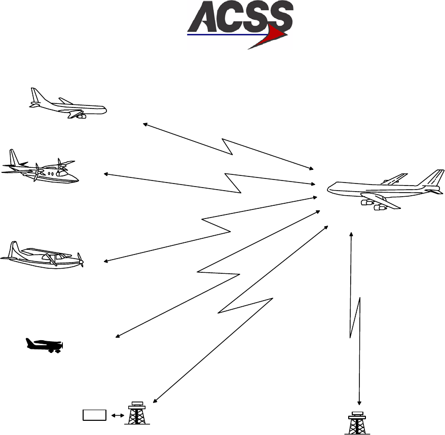
Figure 1−1 shows the various types of intruder equipment and the resulting advisories. It
should be noted that Mode A equipped intruders result in detection and display of TAs
only. An intruder not equipped with a transponder is invisible to TCAS.
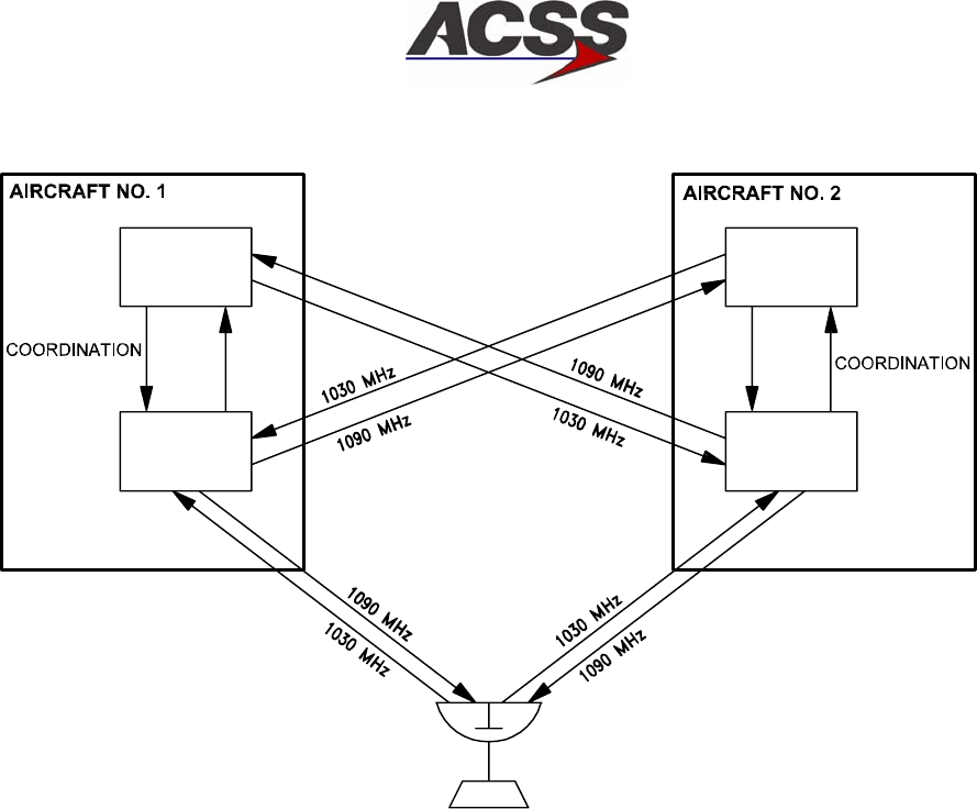
Communication with another TCAS equipped aircraft is provided by an onboard diversity
Mode S transponder. Only one onboard Mode S transponder is required for TCAS
operation. However, the ACSS TCAS 3000 operates with either of two onboard Mode S
transponders, one of which operates as a spare. The transponder in use is selectable
from the cockpit. Figure 1−2 shows the communication between two TCAS equipped
aircraft.
SYSTEM DESCRIPTION AND INSTALLATION MANUAL
TCAS 3000 Traffic Alert and Collision Avoidance System
34−43−23
Use or disclosure of information on this page is subject to the restrictions in the proprietary notice of this document.
Page 1−8
15 Dec 2005
MODE− S RECEIVER
AD−51674−R1@
RA
BROADCAST
MESSAGE
TCAS II
MODE−S
RADAR
RA
MESSAGE
ATCRBS (MODE−A)
TAs
ATC
RAs
RAs
ATCRBS (MODE−C)
MODE−S/TCAS I
TCAS II COORDINATION
AND RAs
SL
COMMAND
Figure 1−1. TCAS ll Advisory Capabilities
SYSTEM DESCRIPTION AND INSTALLATION MANUAL
TCAS 3000 Traffic Alert and Collision Avoidance System
34−43−23
Use or disclosure of information on this page is subject to the restrictions in the proprietary notice of this document.
Page 1−9
15 Dec 2005
GROUND
STATION
AD−53001@
TCAS
CU
MODE S
XPDR MODE S
XPDR
TCAS
CU
Figure 1−2. TCAS/Mode S Communication
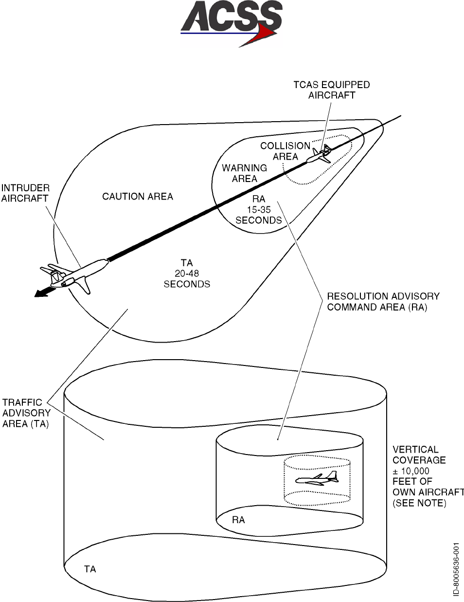
The TCAS 3000 generates both RAs and TAs when the TA/RA mode is selected. The
two types of advisories correspond to time−based protection zones around the aircraft.
The airspace around the TCAS aircraft where an RA is annunciated represents the
warning area, while the larger airspace which results in a TA being annunciated is the
caution area. Figure 1−3 contrasts the airspace covered by the two types of advisories.
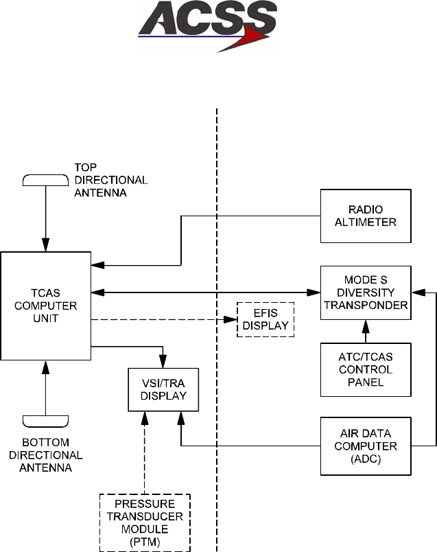
The onboard equipment listed below must be linked to the TCAS 3000 as shown in
Figure 1−4.
•Mode S transponder with associated antennas
•Radio altimeter
•Air Data Computer (ADC) (digital or analog). If an ADC does not support vertical
speed rate data, an optional PTM must be used if the display is a ACSS VSI/TRA.
•ATC/TCAS control panel. A separate control panel is not the only method of control
for the TCAS. Other components, such as a Honeywell Radio Management Unit
(RMU) as part of a Primus II Integrated Radio System, can be used.
•Omnidirectional antenna. The TCAS 3000 accepts two types of bottom antennas: A
standard directional antenna or an optional ATC−type omnidirectional antenna. If an
omnidirectional antenna is installed, it must be supplied by the installer. If a directional
antenna is installed at both top and bottom antenna locations, a bottom
omnidirectional antenna is not needed.
SYSTEM DESCRIPTION AND INSTALLATION MANUAL
TCAS 3000 Traffic Alert and Collision Avoidance System
34−43−23
Use or disclosure of information on this page is subject to the restrictions in the proprietary notice of this document.
Page 1−10
15 Dec 2005
Figure 1−3. TA/RA Airspace Coverage
SYSTEM DESCRIPTION AND INSTALLATION MANUAL
TCAS 3000 Traffic Alert and Collision Avoidance System
34−43−23
Use or disclosure of information on this page is subject to the restrictions in the proprietary notice of this document.
Page 1−11
15 Dec 2005
TCAS 3000 UNITS AIRCRAFT INTERFACE UNITS
AD−31666−R2@
NOTE: DASHED BOXES / LINES DENOTE OPTIONAL ALTERNATE
COMPONENTS. THE PTM IS AN ALTERNATE FOR THE ADC
AND THE EFIS IS AN ALTERNATE FOR THE VSI/TRA.
Figure 1−4. Basic TCAS ll Installation
B. System Configurations
The TCAS 3000 may be installed in several different configurations depending on the
transponders used and the choice of antennas and displays. Some typical configurations
are shown in Figure 1−5. Other combinations are feasible. Figure 1−6 shows the signals
and overall interconnects for a typical TCAS 3000 installation with dual transponders.
•Configuration A shows the TCAS linked to dual Mode S transponders. The system
operates with either transponder, depending on the control panel selection. The
second transponder is used as a backup.
•Configuration B shows the TCAS linked to a single transponder Mode S transponder
system.
•Configuration C shows the TCAS linked to a single Mode S transponder (active) and
an ATCRBS transponder (backup). The TCAS only operates when the Mode S
transponder is selected.
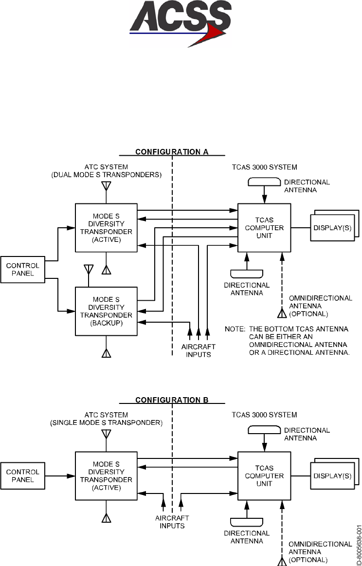
SYSTEM DESCRIPTION AND INSTALLATION MANUAL
TCAS 3000 Traffic Alert and Collision Avoidance System
34−43−23
Use or disclosure of information on this page is subject to the restrictions in the proprietary notice of this document.
Page 1−12
15 Dec 2005
Figure 1−5 (Sheet 1). Typical System Configurations
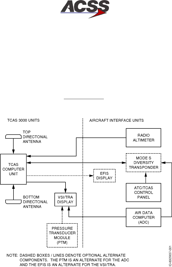
SYSTEM DESCRIPTION AND INSTALLATION MANUAL
TCAS 3000 Traffic Alert and Collision Avoidance System
34−43−23
Use or disclosure of information on this page is subject to the restrictions in the proprietary notice of this document.
Page 1−13
15 Dec 2005
Configuration C
Figure 1−5 (Sheet 2). Typical System Configurations

SYSTEM DESCRIPTION AND INSTALLATION MANUAL
TCAS 3000 Traffic Alert and Collision Avoidance System
34−43−23
Use or disclosure of information on this page is subject to the restrictions in the proprietary notice of this document.
Page 1−14
15 Dec 2005
Blank Page
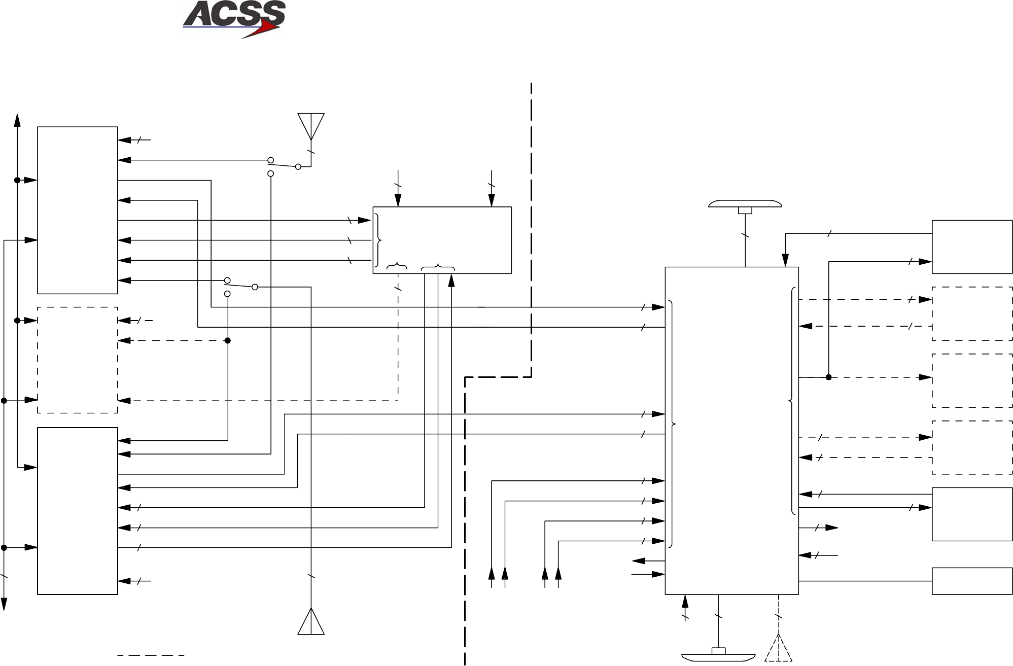
SYSTEM DESCRIPTION AND INSTALLATION MANUAL
TCAS 3000 Traffic Alert and Collision Avoidance System
34−43−23
Use or disclosure of information on this page is subject to the restrictions in the proprietary notice of this document.
Page 1−15/(1−16 blank)
15 Dec 2005
TO/FROM AIRCRAFT
FUNCTIONS
(OTHER THAN TCAS)
BP
BP TP
TP
TP
MP
2INPUT
POWER
INPUT
POWER
3
2
2
DISCRETE
429 BUS
DISCRETE
1 COAX
COAX
DISCRETE
DISCRETE
2
1
429 BUS
RP
LP LP
23
22
2
2
2
2
429 BUS
ANALOG DISCRETE
2
3
OR
429 BUS
OR
ANALOG DISCRETE
2
3
RMP
4COAX
LTP
RMP
RBP
LBP LMP LMP
24COAX 1COAX
12
DISCRETE 2
429 BUS
1
DISCRETE
2
429 BUS
2
DISCRETE
1
TA DISPLAY
MODE S
TRANSPONDER
ATCRBS
TRANSPONDER
BACKUP
MODE S
TRANSPONDER
TO AIRCRAFT
MUTUAL
SUPPRESSION
BUS
TCAS/MODE S
CONTROL
PANEL
TCAS
CU
AD−53000@
RA/TA
DISPLAY 1
RA DISPLAY
1
RA DISPLAY
2
RA/TA DISPLAY
2
115V, 400 HZ
INPUT PWR 5 VAC
PNL LTG
RADIO
ALTIMETER
NO. 1
RADIO
ALTIMETER
NO. 2
TOP DIRECTIONAL
ANTENNA
BOTTOM DIRECTIONAL
ANTENNA
INPUT
POWER
COAX
1
BOTTOM OMNI
ANTENNA
1 DISCRETE
DISCRETE
TO MISC
AIRCRAFT
FUNCTIONS
MP,TP
MP,TP 3
2
429 BUS
ANNUNCIATOR
AUDIO/VISUAL
OPTIONAL
MODE S/ATCRBS
TRANSPONDER
SYSTEM
TCAS 2000
SYSTEM
XT 429 BUS 1
TX 429 BUS 1
TX 429 BUS 2
XT 429 BUS 2
INPUT PWR
(115V, 400 HZ
OR 28V DC)
BUS
LBP
TP
TOP ANTENNA
BOTTOM
ANTENNA
32
CONFIGURATION STRAPS
(OPTIONAL
BACKUP)
2
2
1
2
429 BUS
(OPTIONAL)
MUTUAL
SUPPRESSION
Figure 1−6. TCAS 3000 System Block Diagram
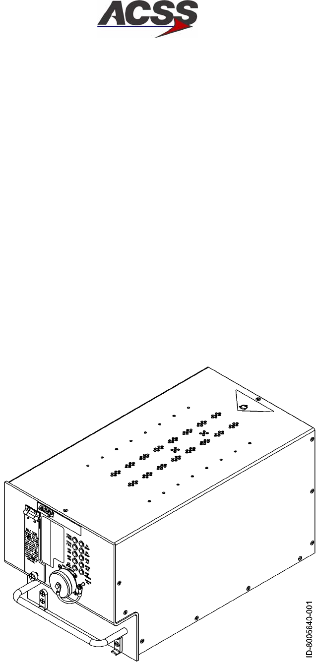
SYSTEM DESCRIPTION AND INSTALLATION MANUAL
TCAS 3000 Traffic Alert and Collision Avoidance System
34−43−23
Use or disclosure of information on this page is subject to the restrictions in the proprietary notice of this document.
Page 1−17
15 Dec 2005
4. Component Descriptions
A. TCAS 3000 Computer Unit
The TCAS Computer Unit (CU) is the heart of the TCAS 3000 system. It contains the RF
transmitter and the receivers necessary to interrogate and receive replies from other
transponder equipped aircraft. Dual microprocessors are utilized to implement the
surveillance and collision avoidance algorithms. The algorithms determine whether an
intruder aircraft should be considered a threat and then determine the appropriate vertical
response to avoid a midair or near midair collision. In addition, output data is provided to
drive displays that inform the flight crew what action to take or avoid.
An interface is provided with an onboard Mode S transponder in order to communicate
with other TCAS ll equipped aircraft. The ACSS TCAS Computer Unit also provides past
and present LRU and system status through the front panel mounted TEST switch and
PASS/FAIL annunciators. Software updates can be incorporated into the computer by an
ARINC 615 data loader port through either the connector mounted on the front panel of
the computer or the port provided on the LRU rear connector or with a compact flash card
inserted into the slot on the front of the LRU.
Figure 1−7 shows a graphical view of the 6MCU TCAS Computer Unit and Figure 1−8
shows a graphical view of the 4MCU TCAS Computer Unit. Table 1−6 provides items and
specifications that are particular to the computer.
Figure 1−7. 6MCU TCAS Computer Unit
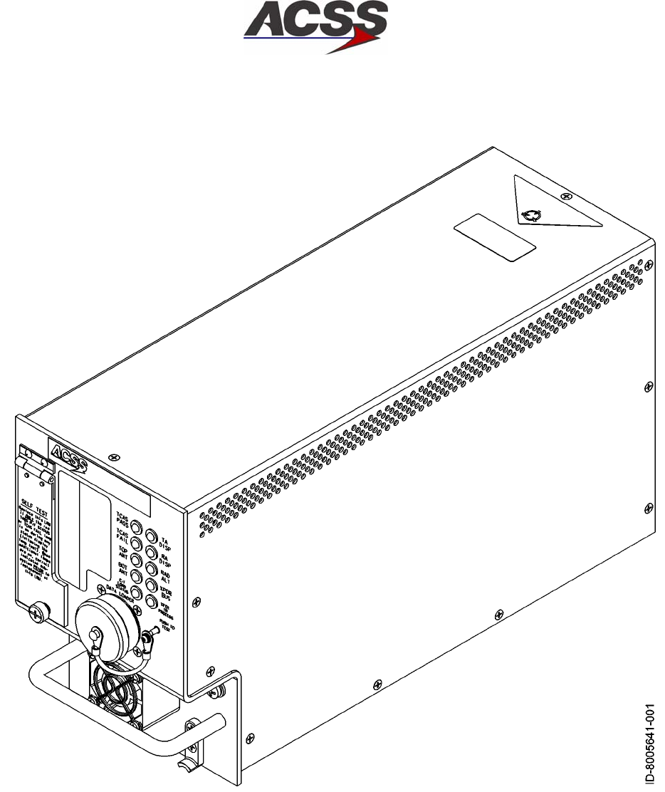
SYSTEM DESCRIPTION AND INSTALLATION MANUAL
TCAS 3000 Traffic Alert and Collision Avoidance System
34−43−23
Use or disclosure of information on this page is subject to the restrictions in the proprietary notice of this document.
Page 1−18
15 Dec 2005
Figure 1−8. 4MCU TCAS Computer Unit

SYSTEM DESCRIPTION AND INSTALLATION MANUAL
TCAS 3000 Traffic Alert and Collision Avoidance System
34−43−23
Use or disclosure of information on this page is subject to the restrictions in the proprietary notice of this document.
Page 1−19
15 Dec 2005
Table 1−6. TCAS 3000 Computer Unit Leading Particulars
Item Specification
Dimensions (maximum):
•Height . . . . . . . . . . . . . . . . . . . . . . . . . . . . . . . . . . . . . . . 7.64 in. (194.1 mm)
•Width (4MCU) . . . . . . . . . . . . . . . . . . . . . . . . . . . . . . . . 4.90 in. (124.5 mm)
•Width (6MCU) . . . . . . . . . . . . . . . . . . . . . . . . . . . . . . . . 7.52 in. (191.0 mm)
•Length (4MCU) . . . . . . . . . . . . . . . . . . . . . . . . . . . . . . . 15.26 in. (387.6 mm)
•Length (6MCU) . . . . . . . . . . . . . . . . . . . . . . . . . . . . . . . 15.76 in. (400.3 mm)
Weight (maximum):
•4MCU DC only version . . . . . . . . . . . . . . . . . . . . . . . . . 14.0 lb (6.37 kg)
•4MCU DC/AC version . . . . . . . . . . . . . . . . . . . . . . . . . .
•6MCU . . . . . . . . . . . . . . . . . . . . . . . . . . . . . . . . . . . . . . .
14.7 lb (6.66 kg)
17.6 lb (8.00 kg)
Operating Voltage:
•dc Voltage . . . . . . . . . . . . . . . . . . . . . . . . . . . . . . . . . . . . +20.5 V dc minimum, +27.5 V dc
nominal, +32.2 V dc maximum
•ac Voltage . . . . . . . . . . . . . . . . . . . . . . . . . . . . . . . . . . . . 97 V rms minimum, 115 V rms nominal,
134 V rms maximum at 400 80 Hz
Power Consumption . . . . . . . . . . . . . . . . . . . . . . . . . . . . . 70 Watts standby, 100 Watts maximum
Circuit Breaker Ratings:
•115 V ac Circuit Breaker . . . . . . . . . . . . . . . . . . . . . . . 5 Amp Typical
•28 V dc Circuit Breaker . . . . . . . . . . . . . . . . . . . . . . . . 10 Amp Typical
Mating Connector:
•P1 (Rear Connector) . . . . . . . . . . . . . . . . . . . . . . . . . . . Radial Part No. 620−800−066
•J1 (Front Connector) . . . . . . . . . . . . . . . . . . . . . . . . . . ACSS Part No. 4004295−160,
ITT Part No. KJ6F18A53P
Mounting:
•6MCU . . . . . . . . . . . . . . . . . . . . . . . . . . . . . . . . . . . . . . . ARINC 600 6−MCU Tray Assembly
•4MCU . . . . . . . . . . . . . . . . . . . . . . . . . . . . . . . . . . . . . . . ARINC 600 4−MCU Tray Assembly
TSO:
•All units . . . . . . . . . . . . . . . . . . . . . . . . . . . . . . . . . . . . . . C119b
ETSO . . . . . . . . . . . . . . . . . . . . . . . . . . . . . . . . . . . . . . . . . . C119b
Software Development Specification . . . . . . . . . . . . . . . DO−178B, Level B
Environmental Specifications . . . . . . . . . . . . . . . . . . . . . . DO−160D Environmental Category
[A2F2]YBB [CLMY][E1]XXXXXZ
[EBZ]A[EZ]ZRZA3EXX

SYSTEM DESCRIPTION AND INSTALLATION MANUAL
TCAS 3000 Traffic Alert and Collision Avoidance System
34−43−23
Use or disclosure of information on this page is subject to the restrictions in the proprietary notice of this document.
Page 1−20
15 Dec 2005
Table 1−6. TCAS 3000 Computer Unit Leading Particulars (cont)
Item Specification
•Temperature / Altitude [A2F2]:
−Operating Temperature . . . . . . . . . . . . . . . . . . . . . . −55 to +70 degrees C
−Ground Survival Temperature . . . . . . . . . . . . . . . . −55 to +85 degrees C
−Altitude . . . . . . . . . . . . . . . . . . . . . . . . . . . . . . . . . . . . Sea Level to 55,000 feet
−Loss of Cooling . . . . . . . . . . . . . . . . . . . . . . . . . . . . . +40 degrees C for 300 minutes minimum
RF Transmitter Characteristics:
•Transmitter Frequency . . . . . . . . . . . . . . . . . . . . . . . . . 1030 ± 0.01 MHz
•RF Peak Output Power:
−Minimum . . . . . . . . . . . . . . . . . . . . . . . . . . . . . . . . . . . 53.3 dBm (210 Watts)
−Nominal . . . . . . . . . . . . . . . . . . . . . . . . . . . . . . . . . . . 55.3 dBm (335 Watts)
−Maximum . . . . . . . . . . . . . . . . . . . . . . . . . . . . . . . . . . 57.3 dBm (540 Watts)
•Unwanted Output Power in an Inactive State . . . . . . −72 dBm
•Pulse Timing Characteristics:
−Pulse Rise Time . . . . . . . . . . . . . . . . . . . . . . . . . . . . 0.05 to 0.10 microseconds
−Pulse Fall Time . . . . . . . . . . . . . . . . . . . . . . . . . . . . . 0.05 to 0.20 microseconds
− ATCRBS S1, P1, P3, P4 Duration . . . . . . . . . . . . 0.08 ± 0.05 microseconds
−Mode S P1, P2 Duration . . . . . . . . . . . . . . . . . . . . . 0.08 ± 0.05 microseconds
−Mode S P6 Duration . . . . . . . . . . . . . . . . . . . . . . . . 16.25 ± 0.125 microseconds (short)
30.25 ± 0.125 microseconds (long)
•Whisper−Shout Characteristics:
−Range . . . . . . . . . . . . . . . . . . . . . . . . . . . . . . . . . . . . . 0 to 26 dB attenuation by 1 dB steps
−Absolute Tolerance . . . . . . . . . . . . . . . . . . . . . . . . . . Relative to the 0 dB step, the attenuation
of each step does not exceed the
nominal attenuation by more than ±2 dB
−Relative Tolerance . . . . . . . . . . . . . . . . . . . . . . . . . . Step increments are ±0.5 dB and
monotonic
RF Receiver Characteristics:
•Receiver Frequency Range . . . . . . . . . . . . . . . . . . . . . 1087 to 1093 MHz
•Receiver MTL Over Frequency . . . . . . . . . . . . . . . . . .
(Normal Operation)
−77 ± 2 dBm (≥90% Mode S and
ATCRBS replies decoded)
•Receiver Dynamic Range . . . . . . . . . . . . . . . . . . . . . .
(Normal Operation)
−77 to −23 dBm (≥99% Mode S and
ATCRBS replies for signal levels greater
than MTL +3 dB)

SYSTEM DESCRIPTION AND INSTALLATION MANUAL
TCAS 3000 Traffic Alert and Collision Avoidance System
34−43−23
Use or disclosure of information on this page is subject to the restrictions in the proprietary notice of this document.
Page 1−21
15 Dec 2005
Table 1−6. TCAS 3000 Computer Unit Leading Particulars (cont)
Item Specification
•Extended Range Reception Capability . . . . . . . . . . .
(Optional Mode)
−82 ± 2 dBm (≥90% Mode S squitter
replies decoded)
•Low Level Receiver Signal Rejection . . . . . . . . . . . . .
(Normal Operation)
−81 dBm (≤10% Mode S and ATCRBS
replies decoded)
•Receiver Signal Processing . . . . . . . . . . . . . . . . . . . . . Amplitude Mono−pulse
•System Bearing Accuracy . . . . . . . . . . . . . . . . . . . . . . Error less than 9 degrees RMS, 27
degrees peak from −10 to +10 degrees
elevation
(1) System Interfaces
The TCAS 3000 Computer Unit supports the external system interfaces that follow.
Unless otherwise specified, the specifications apply to both the 6−MCU and 4−MCU
computers. All interfaces are per ARINC 735A.
(a) Radio Altimeter Interface
The TCAS 3000 Computer Unit accepts either analog or digital radio altimeter
inputs. For each type of input, dual input ports are provided.
Each of the military radio altimeter types provide two outputs that are connected
to the TCAS CU input pins. The two altimeter outputs are the Analog Data
Output and Analog Data Reliability signal. The TCAS CU uses the Data
Reliability signal in conjunction with the Analog Data Output to determine radio
altimeter failures.
A condition exists for several military radio altimeters known as Out of Track.
This condition occurs when the radio altimeter has not failed and the altimeter is
not reading a valid altitude. Altitude data for an Out of Track condition should be
considered invalid and not used.
The digital radio altimeter interface accepts inputs from an ARINC 707 radio
altimeter on ARINC 429 low speed input busses.
(b) Mode S Transponder Interface
The TCAS 3000 computer contains two sets of ARINC 429 high speed busses
for communication with two Mode S transponders. It uses ARINC 718−A/735
communication protocol (2 inputs, 2 outputs).
(c) Onboard Maintenance System Interface
The TCAS 3000 computer contains a set of ARINC 429 low speed busses for
communication with an onboard maintenance system (1 input, 1 output). The
unit interfaces with all major airframe manufacturers maintenance computer
systems. Since the maintenance computer protocol for each airframe
manufacturer is different, the TCAS 3000 automatically detects the type of
airframe from the data received from the maintenance computer and sets its
protocol accordingly.

SYSTEM DESCRIPTION AND INSTALLATION MANUAL
TCAS 3000 Traffic Alert and Collision Avoidance System
34−43−23
Use or disclosure of information on this page is subject to the restrictions in the proprietary notice of this document.
Page 1−22
15 Dec 2005
(d) Data Loader Interface
The TCAS 3000 computer contains a set of ARINC 429 busses and discrete
inputs that interface to either an airborne data loader (ADL) through pins on the
rear connector, or a portable data loader (PDL) through the 53−pin circular
connector on the front panel of the unit. The computer works with ARINC 615
data loader protocol (high speed bus). The unit software part number can be
output on the data loader port by grounding a discrete input.
(e) RS−232 / Compact Flash Card Data Recorder Interface
The Data Recorder Interface can be utilized for either internal or external data
recording.
The TAWS/RWS event log contains event information due to TAWS or windshear
cautions or warnings (internal data recording). The log can hold approximately
three events that last up to 45 seconds each (assuming GCAM Event, GCAM
parameter data, and GFM parameter data selected for recording). The event
log data may be downloaded to a Laptop PC over the RS−232 port, or
downloaded to a Compact Flash card using the slot on the front of the unit.
The external data recording provides the capability to perform real−time
recording of various T2CAS input, output, and internal data. This data may be
recorded using the Compact Flash card or RS−232 interface.
In addition, the RS−232 interface allows for LRU maintenance and
troubleshooting. The maintenance log and RA event log can also be
downloaded to a PC using this port. The RS−232 interface is connected to the
53−pin PDL connector on the front of the unit.
(f) TCAS Display Bus interface
The TCAS 3000 computer has four sets of ARINC output busses for display of
traffic and resolution advisories.
The TA/RA Display No. 1 and No. 2 busses are high speed ARINC 429 busses
that contain both traffic information and resolution advisory information. The
busses function according to either the ARINC 735 characteristics, or can
optionally be set for the Honeywell EFIS characteristics through a program input
pin (RMP−12C). For each bus, a valid discrete input is provided that indicates
whether the display is functional.
The RA Display No. 1 and No. 2 busses are low speed ARINC 429 busses that
contain only resolution advisory information. The busses function according to
the ARINC 735 characteristics. For each bus, a valid discrete is provided that
indicates whether the display is functional.
The RA Display No. 1 and No. 2 busses can be configured for a 429 Data
Recorder function by grounding programming pin (RMP−11D). In this mode, the
busses are configured for high speed operation.

SYSTEM DESCRIPTION AND INSTALLATION MANUAL
TCAS 3000 Traffic Alert and Collision Avoidance System
34−43−23
Use or disclosure of information on this page is subject to the restrictions in the proprietary notice of this document.
Page 1−23
15 Dec 2005
(g) Performance Management Bus Interface
The TCAS 3000 computer contains a low speed ARINC 429 bus input
(RMP−6A,6B) that is reserved for connection to a performance management
system. The input is provisioned to obtain maximum rate of climb information
from a FMS or Performance Management System (PMS.) The input is provided
for future system enhancements and is currently not used.
(h) Magnetic Heading/Attitude Bus Interface
The TCAS 3000 computer contains a high speed ARINC 429 bus input
(RMP−7A, 7B) that is reserved for connection to an Inertial Reference System
(IRS). The input lets aircraft heading and attitude data be input for the purpose
of providing for future horizontal maneuvers. This function has not been
implemented on TCAS II installations, so these pins are reserved for future use.
(i) Compact Flash Flight Data Recorder Interface
The TCAS 3000 computer contains a Compact Flash card interface that provides
flight data recording capability.
(j) ARINC 573 Flight Data Recorder Interface
The TCAS 3000 computer contains 12 discrete outputs that can be connected to
an ARINC 573 flight data recorder. The outputs are used to record information
during a resolution advisory event.
(k) ARINC 429 Flight Data Recorder Interface
The TCAS 3000 computer contains an interface for an ARINC 429 flight data
recorder. The flight data recorder function is activated by grounding a discrete
input pin (RMP−11D) on the rear connector. With the discrete input grounded,
flight data is output as high speed ARINC 429 data on the RA Display No. 1 and
No. 2 busses. With the discrete grounded, the normal RA Display bus operation
is not available.
(l) Voice Audio Outputs
The TCAS 3000 computer contains two analog audio outputs that provide TCAS
aural traffic advisories and resolution advisories. The 8−Ohm output has the
capability to supply up to 4 Watts RMS into a speaker. The 600−Ohm output has
the capability to supply up to 80 milliwatts RMS into an audio distribution system.
(m) RS−232 Interface
The TCAS 3000 computer has an RS−232 input/output for connection to a
personal computer. The interface allows for LRU maintenance and
troubleshooting. The maintenance log and RA event log can also be
downloaded to a PC using this port. The RS−232 interface is connected to the
53−pin PDL connector on the front of the unit.

SYSTEM DESCRIPTION AND INSTALLATION MANUAL
TCAS 3000 Traffic Alert and Collision Avoidance System
34−43−23
Use or disclosure of information on this page is subject to the restrictions in the proprietary notice of this document.
Page 1−24
15 Dec 2005
(n) Altitude Alerter Interface
The TCAS 3000 computer contains an ARINC 429 low speed input bus that is
reserved for receiving selected altitude information from an altitude control
source or flight control computer. The TCAS computer uses the selected altitude
information to inhibit the weakening of a resolution advisory by determining the
selected altitude limits for the aircraft.
(o) Reserved ARINC 429 Bus Interface
The TCAS 3000 computer has four sets of reserved ARINC 429 input busses
that can be configured as either high speed or low speed. These busses allow
for future upgrades to the TCAS 3000 system without hardware modification.
(2) Discrete Inputs
The TCAS 3000 has various discrete inputs available for implementing various TCAS
functions. The input logic status is defined according to ARINC 735 definition.
(3) Program Inputs
The TCAS 3000 has various program inputs available for unit configuration and
installation programming. Input logic status is defined according to ARINC 735
definition.
(4) Discrete Outputs
The TCAS 3000 has a number of discrete outputs that are used for unit status
annunciation and data output functions. The output logic status is defined according
to ARINC 735 definition.
(5) Self−Test Function
By momentarily pushing the TEST switch on the front panel of the TCAS Computer
Unit, maintenance personnel can display fault data for the current and preceding
flight legs. When TEST is initially activated, all annunciators (pass/fail lamps on front
of unit) are ON for a 3−second lamp test, then current fault data is displayed for 10
seconds. If no further activations of the TEST switch are made, the LRU display
cycle is terminated at the end of the 10−second fault display period, and all
annunciators are extinguished.
If during the 10−second fault display period, the TEST button is activated again, the
fault display period is aborted, a 2−second lamp test cycle is done, and the fault data
recorded for the preceding flight leg is displayed for 10 seconds. This procedure can
be repeated up to 10 times to obtain recorded data from the previous 10 flight legs.
If the TEST button is not activated again during the fault display period, the fault
display cycle is terminated at the end of the 10−second fault display period and all
annunciators are extinguished. If an attempt is made to display fault data for the
preceding flight leg when the tenth preceding flight leg fault data is displayed, all
annunciators flash for a 3−second period at a 2.5−Hz rate, after which all
annunciators are extinguished.

SYSTEM DESCRIPTION AND INSTALLATION MANUAL
TCAS 3000 Traffic Alert and Collision Avoidance System
34−43−23
Use or disclosure of information on this page is subject to the restrictions in the proprietary notice of this document.
Page 1−25
15 Dec 2005
When less than 10 flight legs have been flown since the TCAS Computer Unit was
shop tested and recertified, less than 10 previous flight legs of recorded fault data
may be available for display. In this case, if an attempt is made to display fault data
for the preceding flight leg when the earliest flight leg is displayed, all annunciators
flash for 3 seconds at a 2.5−Hz rate and then all annunciators are extinguished.
The TCAS PASS and TCAS FAIL annunciators indicate the status of the TCAS
Computer Unit only. All other annunciators reflect the condition of the respective
sub−system. During troubleshooting, the TCAS Computer should not be removed if
the TCAS PASS lamp is on.
B. Directional Antenna
The TCAS directional antenna, Figure 1−9, is a four−element, vertically polarized,
monopole array capable of transmitting in four selectable directions at 1030 MHz. The
antenna is capable of receiving replies from all directions simultaneously with bearing
information at 1090 MHz, using amplitude−ratio monopulse techniques.
The antenna consists of a molded radome with radiating/receiving elements and is
completely filled with a rigid foam. The antenna assembly uses five or nine screws to
attach the radome and either four or eight screws to attach the antenna to the aircraft
fuselage.
The ACSS directional antenna has a small frontal area. The circular radome has a 3:1
elliptical leading edge and an extremely low profile height of only 0.806 inch. This yields
excellent aerodynamic performance with a minimum possibility of icing, which could be a
hazard for rear mounted engines.
For TCAS 3000 system installations, the top antenna must be a directional antenna. The
bottom antenna can be either a directional or omnidirectional antenna. The TCAS
Computer Unit has the capability of automatically sensing which version is installed.
The directional antenna mounting screws (not included with the directional antenna) are
standard #10−32 UNF−2A pan head, corrosion−resistant (stainless) steel screws in
accordance with Military Specification MS51958. The appropriate length is determined by
the installer allowing 0.5−inch for the thickness of the antenna and adapter plate. A
washer must be installed under the head of each mounting screw. The washer must be
made of passivated, corrosion−resistant steel in accordance with MIL−S−5059 or
MIL−S−6721. The Air Force−Navy Aeronautical Standard part number is AN960C10L.
The washer has an outer diameter of 0.438 inch, an inner diameter of 0.203 inch, and a
thickness of 0.032 inch.

SYSTEM DESCRIPTION AND INSTALLATION MANUAL
TCAS 3000 Traffic Alert and Collision Avoidance System
34−43−23
Use or disclosure of information on this page is subject to the restrictions in the proprietary notice of this document.
Page 1−26
15 Dec 2005
An O−ring (included with the directional antenna) is required to be installed between the
directional antenna and the aircraft fuselage. The Navy Aeronautical Standard part
number for the O−ring is NAS 1611−240. The ACSS part number for the O−ring is
4000171−240.
NOTE: For directional antennas, ACSS Part No. 7514060−90X, the customer must
provide an adapter plate for mounting to the aircraft. For details of the antenna
base plate, to which the adapter must mate, refer to Section 2. Directional
antennas, ACSS Part No. 7514081−9XX, come with a preinstalled adapter plate.
The average unit weight of an antenna with adapter plate is approximately 3.0 pounds.
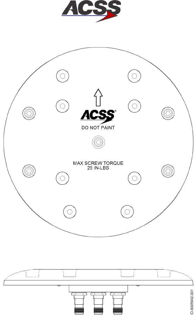
SYSTEM DESCRIPTION AND INSTALLATION MANUAL
TCAS 3000 Traffic Alert and Collision Avoidance System
34−43−23
Use or disclosure of information on this page is subject to the restrictions in the proprietary notice of this document.
Page 1−27
15 Dec 2005
Figure 1−9. Directional Antenna
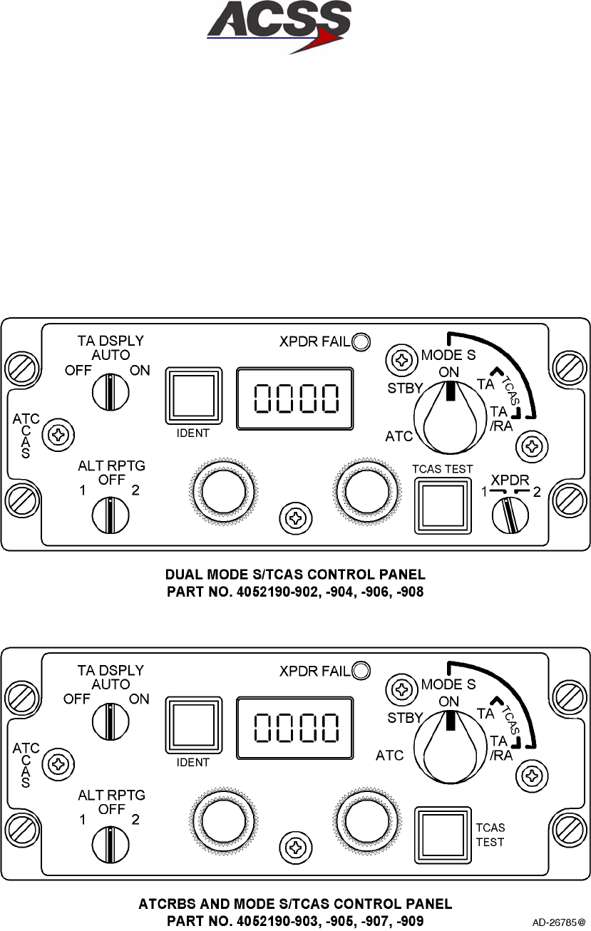
SYSTEM DESCRIPTION AND INSTALLATION MANUAL
TCAS 3000 Traffic Alert and Collision Avoidance System
34−43−23
Use or disclosure of information on this page is subject to the restrictions in the proprietary notice of this document.
Page 1−28
15 Dec 2005
C. ACSS Mode S/TCAS Control Panels
The ACSS control panels for the transponder and TCAS systems provide mode control
for dual or single ATC Mode S Transponders and TCAS ll systems. Figure 1−10 shows a
typical front panel layout of the two configurations. It is usually mounted in the aircraft
instrument panel or the pedestal. Table 1−7 gives items and specifications particular to
the unit.
Figure 1−10. ACSS Control Panels

SYSTEM DESCRIPTION AND INSTALLATION MANUAL
TCAS 3000 Traffic Alert and Collision Avoidance System
34−43−23
Use or disclosure of information on this page is subject to the restrictions in the proprietary notice of this document.
Page 1−29
15 Dec 2005
Table 1−7. ACSS Control Panel Leading Particulars
Item Specification
Dimensions (maximum):
•Height . . . . . . . . . . . . . . . . . . . . . . . . . . . . . . . . . . . . . . . 2.25 in. (57.2 mm)
•Width . . . . . . . . . . . . . . . . . . . . . . . . . . . . . . . . . . . . . . . . 5.75 in. (146.1 mm)
•Length . . . . . . . . . . . . . . . . . . . . . . . . . . . . . . . . . . . . . . . 5.00 in. (127.0 mm)
Weight (maximum) . . . . . . . . . . . . . . . . . . . . . . . . . . . . . . 2.1 lb (0.953 kg)
Power Requirements:
•Primary . . . . . . . . . . . . . . . . . . . . . . . . . . . . . . . . . . . . . . 115 V, 400 Hz (2.0 Watts maximum)
•Lighting . . . . . . . . . . . . . . . . . . . . . . . . . . . . . . . . . . . . . . 5 V, 400 Hz (3.0 Watts maximum)
Mating Connectors:
•J1 . . . . . . . . . . . . . . . . . . . . . . . . . . . . . . . . . . . . . . . . . . . M83723/75R1624S7
•J2 (Dual Mode S Version) . . . . . . . . . . . . . . . . . . . . . . M83723/75R1624S8
•J2 (ATCRBS/Mode S Version) . . . . . . . . . . . . . . . . . . MS3476L2041S
Mounting . . . . . . . . . . . . . . . . . . . . . . . . . . . . . . . . . . . . . . . Unit Dzus Fasteners
(1) Functional Description and Operation
Communication with Mode S transponders is accomplished through an ARINC 429
bus as defined in ARINC Characteristic 718−A. Control panel functions include 4096
ident code selection and display, altitude source and reporting inhibit selection,
selection between two onboard transponders, TCAS TA or TA/RA advisory selection,
and selection of TCAS test. A listing of the control panel switch functions is as
follows:
(a) ALT RPGT Switch − 1, OFF, 2
Used to select between altitude sources 1 and 2, or to disable altitude reporting
in transponder replies.
(b) XPDR FAIL − Annunciator
The illumination of the annunciator is an indication of a performance monitor
failure detection.
(c) Mode Control − Rotary Switch
Disables reply capability in STANDBY mode. Enables MODE S transponder in
ON mode. Enables ATCRBS transponder in ATC mode. The TA mode enables
the TCAS computer, in conjunction with the Mode S transponder, to provide
traffic advisories. The TA/RA mode enables the TCAS computer, in conjunction
with the Mode S transponder, to provide traffic and resolution advisories. The TA
and TA/RA modes are electrically tied to the ON mode and enable the Mode S
transponder when selected.
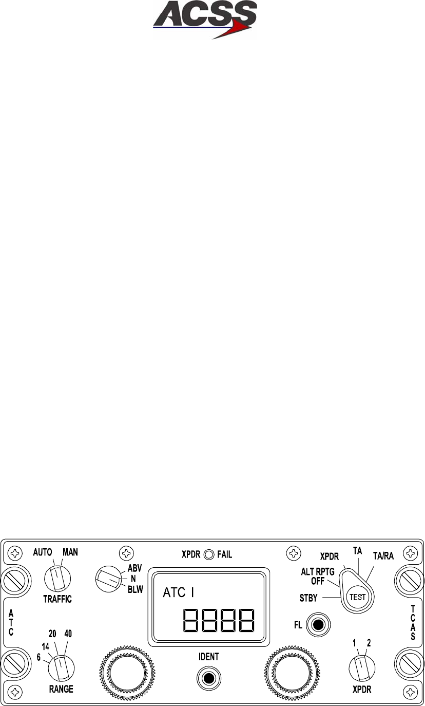
SYSTEM DESCRIPTION AND INSTALLATION MANUAL
TCAS 3000 Traffic Alert and Collision Avoidance System
34−43−23
Use or disclosure of information on this page is subject to the restrictions in the proprietary notice of this document.
Page 1−30
15 Dec 2005
(d) XPDR − Selector Switch (Dual Mode S Versions Only)
Selects the transponder, 1 or 2, that is used for reporting replies.
(e) TA DSPLY − OFF, AUTO, ON
Controls the operation of the navigation or traffic advisory display for a TCAS
system.
(f) TCAS TEST − Button
Used to select the TCAS system self−test function.
(g) IDENT − Button
When pushed, this button causes an ATCRBS reply, or Mode S UF−4 and UF−5
replies, to contain a special identifier pulse (SPI) as an identifier to the ground
according to ARINC 718−A Draft 5 of Supplement 4.
(h) 4096 Ident Code − Dual Concentric Rotary Knobs
Each rotary switch is used to set each individual digit of the four−digit ident code.
The left inner knob selects the thousands digit, left outer knob selects the
hundreds digit, right inner knob selects the tens digit, and the right outer knob
selects the ones digit.
D. Gables ATC/TCAS Dual Mode S Transponder Control Panel
The Gables ATC/TCAS Mode S control panel is used to independently control two Mode
S transponders, and to interface with a Mode S installation with TCAS capabilities.
The control panel contains two isolated electronic modules each dedicated to a given
transponder. Each module derives its input ATC code data from two dual concentric
knobs. The selected code is then displayed on a four digit Liquid Crystal Display (LCD),
and subsequently transmitted to each transponder.
Figure 1−11 shows a typical front panel layout of a Gables G7130 series control panel.
Table 1−8 gives items and specifications that are particular to these units.
ID−53838−R2
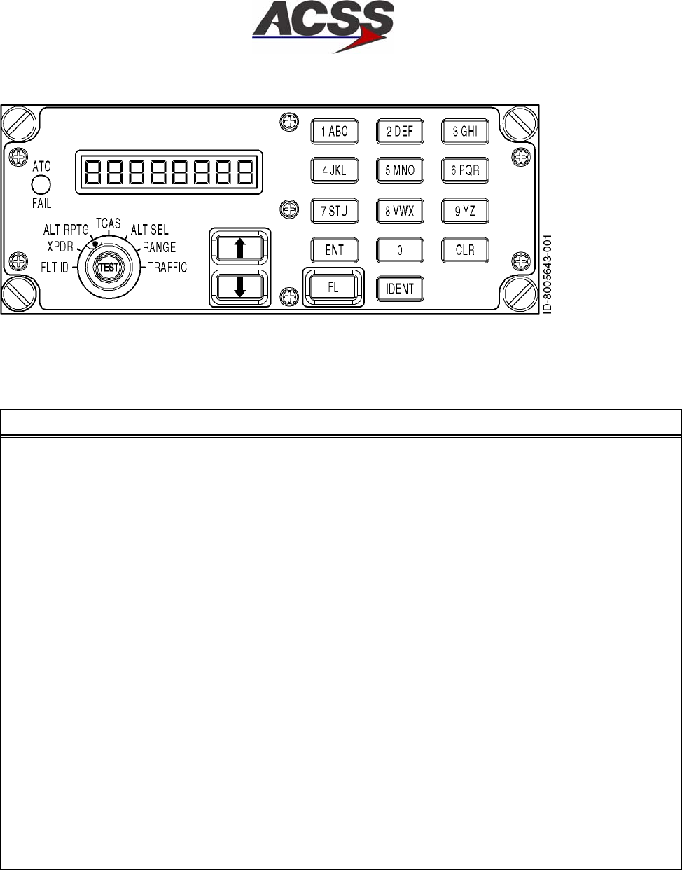
SYSTEM DESCRIPTION AND INSTALLATION MANUAL
TCAS 3000 Traffic Alert and Collision Avoidance System
34−43−23
Use or disclosure of information on this page is subject to the restrictions in the proprietary notice of this document.
Page 1−31
15 Dec 2005
Figure 1−11. Typical Gables ATC/TCAS Control Panel
Table 1−8. Gables G7130/G7490 Series Control Panel Leading Particulars
Item Specification
Dimensions (maximum):
•Height . . . . . . . . . . . . . . . . . . . . . . . . . . . . . . . . . . . . . . 2.25 in. (57.2 mm)
•Width . . . . . . . . . . . . . . . . . . . . . . . . . . . . . . . . . . . . . . . 5.75 in. (146.1 mm)
•Length . . . . . . . . . . . . . . . . . . . . . . . . . . . . . . . . . . . . . . 5.80 in. (147.3 mm)
Weight (maximum) . . . . . . . . . . . . . . . . . . . . . . . . . . . . . 2.0 lb (0.907 kg)
Power Requirements:
•Primary . . . . . . . . . . . . . . . . . . . . . . . . . . . . . . . . . . . . . +28 V dc, 0.25 Amps maximum current
•Display and Overlay Lighting . . . . . . . . . . . . . . . . . . . 5 V, 400 Hz, 2.3 Amps maximum
Display Type . . . . . . . . . . . . . . . . . . . . . . . . . . . . . . . . . . . Four Digit, Dichroic LCD
Code Select Range . . . . . . . . . . . . . . . . . . . . . . . . . . . . . 0000 to 7777 (octal)
Transmitted ARINC 429 Labels . . . . . . . . . . . . . . . . . . . 013, 015, 016, 031 (octal)
TSO . . . . . . . . . . . . . . . . . . . . . . . . . . . . . . . . . . . . . . . . . . C112/C119
Environmental Specifications . . . . . . . . . . . . . . . . . . . . . /A2D1/BB/MB·/XXXXXXZZAZZRZ/xxZZ
Mating Connectors:
•J1 . . . . . . . . . . . . . . . . . . . . . . . . . . . . . . . . . . . . . . . . . . M83723/75R16247 or MS24266R16B24S7
•J2 . . . . . . . . . . . . . . . . . . . . . . . . . . . . . . . . . . . . . . . . . M83723/75R16248 or MS24266R16B24S8
Mounting . . . . . . . . . . . . . . . . . . . . . . . . . . . . . . . . . . . . . . Four Unit Dzus Fasteners

SYSTEM DESCRIPTION AND INSTALLATION MANUAL
TCAS 3000 Traffic Alert and Collision Avoidance System
34−43−23
Use or disclosure of information on this page is subject to the restrictions in the proprietary notice of this document.
Page 1−32
15 Dec 2005
(1) Functional Description and Operation
Communication with Mode S transponders is accomplished through an ARINC 429
bus as defined in ARINC Characteristic 718−A. Control panel functions include 4096
ident code selection and display, altitude source and reporting inhibit selection,
selection between two onboard transponders, TCAS TA or TA/RA advisory selection,
range selection (in nautical miles) and a system functional test selection. A
description of the front panel annunciator and switch functions follows:
(a) Transponder Code Display
The control panel has a single LCD display that is common to both modules
within the unit. The display shows the ATC code selected by the user and
consequently transmitted to the transponders. Input to the display is controlled
by the system select switch (XPNDR 1−2).
In addition, certain fault indications are also indicated on the display. After a
functional test has been initiated, PASS shows on the display after a successful
test, or it shows FAIL if a high level failure is detected under normal operating
conditions. It also shows which transponder is active by displaying ATC 1 or 2.
(b) ATC Code Selection
The ATC four digit code is selected with two dual concentric sets of knobs. Each
knob is dedicated to a single liquid crystal display (LCD) digit on the LCD code
display. The two smaller knobs control the inner digits of the LCD (tens and
hundreds) while the two larger knobs control the outer most digits (units and
thousands).
(c) XPNDR 1−2 Switch
The XPNDR switch is a two position switch that allows the selection of one
Mode−S module in the control panel, and the activation of its associated
transponder (System 1 or System 2).
(d) Mode Control Selector Switch
The rotary switch labeled STBY−ALT RPTG OFF−XPNDR−TA ONLY−TA/RA
allows the operator to activate the TCAS system by selecting TA, or traffic and
resolution advisory (TA/RA). When STBY is selected, both transponders are
selected inactive or in standby mode. Altitude reporting off (ALT RPTG OFF)
selection disables the altitude data sources interrupting transmission of aircraft
altitude and location information to ground controllers.
(e) ABV/N/BLW Switch
The ABV/N/BLW switch selects an altitude range (from aircraft) for traffic display
on the TCAS displays. Range limits are 9900 feet above and 2700 feet below
the aircraft when in ABV mode and 2700 feet above and 9900 below the aircraft
when in BLW mode. When the normal (N) position is selected, the display range
is 2700 feet above and below the aircraft.

SYSTEM DESCRIPTION AND INSTALLATION MANUAL
TCAS 3000 Traffic Alert and Collision Avoidance System
34−43−23
Use or disclosure of information on this page is subject to the restrictions in the proprietary notice of this document.
Page 1−33
15 Dec 2005
(f) Traffic Display Switch
The TRAFFIC AUTO−MAN switch is a two position rotary switch that controls the
TCAS traffic display mode of operation. When the AUTO mode is selected, the
TCAS computer sets the TCAS displays to pop−up mode under a
traffic/resolution advisory condition. If the MAN mode is selected, then the TCAS
displays will be constantly activated advising of any near by traffic detected
within the horizontal and vertical range limits.
(g) Range Switch
The RANGE switch is a four or six position rotary switch used to select among
different nautical mile (NM) traffic advisory horizontal range displays.
(h) IDENT Key
The IDENT key is a momentary button. When pushed, the IDENT key causes
an ATCRBS reply or Mode S UF−4 and UF−5 replies to contain a special pulse
identifier pulse (SPI) as an identifier to be transmitted to ground controllers in
accordance with ARINC 718−A Draft 5 of Supplement 4.
(i) Flight Level Button
The FL button is a momentary button used to select between relative and
absolute altitude information. When absolute is selected, this mode is enabled
for approximately 20 seconds and then reverts back to relative.
(j) Test Button
The TEST button enables the user to initiate a system functional test. When the
TEST button is pushed, the control panel initiates an internal test while a
functional test output is also transmitted through ARINC 429 labels.
When installed with a TCAS system, an extended test can be initiated by
continuously pushing the TEST button for at least eight seconds.
(k) XPNDR FAIL Annunciator
The XPNDR FAIL annunciator displays the functional status of the active
transponder. The fail annunciator lights only when a failed transponder is
selected on the XPNDR 1−2 switch.
(l) FID Switch
The Keypad is used to create or enter the Flight ID for output by the transponder.
The display will show the Flight ID code that has been entered by the crew. The
FID light will illuminate when in this mode.
When FID mode is selected, all keys are active. The active keys are used to
create the Aircraft Flight ID code for transmission to ATC.

SYSTEM DESCRIPTION AND INSTALLATION MANUAL
TCAS 3000 Traffic Alert and Collision Avoidance System
34−43−23
Use or disclosure of information on this page is subject to the restrictions in the proprietary notice of this document.
Page 1−34
15 Dec 2005
For 0 thru 9, press the appropriate digit to enter a new code. When the first digit
of a new code is pressed, the digit display field is cleared, the display shows that
digit in the left−most digit field with the other digits blanked and the FID indicator
will flash. CLR can be pressed while in the process of entering digits to clear the
digit field and allow entry of a new code. Pressing CLR again will result in the
display of the previously active code. Upon completing entry of the FID cod,
pressing ENT results in transmission of the new FID in about five (5) seconds. If
the ATC mode is selected before pressing ENT, the partial entry is retained in
memory and the FID indicator continues to flash. Upon returning to the FID
mode, the new FID code entry process can be completed. The FID indicator will
stop lashing when ENT is pressed.
For letters A−Z, repeatedly press the appropriate key until the desired letter
appears in the display. The first press of any key will cause the digit to appear in
the display. The second press of the same key within 2 seconds will cause the
digit to change to the first letter on that key. The third press of the same key
within 2 seconds will cause the letter to change to the second letter on that key.
The next press within 2 seconds will cause the letter to change to the third letter
on the key pad (if applicable). The next press within 2 seconds will cause the
letter to change back to the digit on the key. Waiting 2 seconds between key
presses, or pressing another key at any time, will advance the cursor to the next
character space or will cause the digit of the key pressed to appear in the next
location on the display. Flight ID can be between 1 and 8 characters in length.
E. VSI/TRA Display
The VSI/TRA display, Figure 1−12, is used to display current vertical speed and TCAS
traffic/warning information. The display consists of a full color, active matrix, liquid crystal
display panel. The display quality compares favorably to CRT displays but requires less
power, weight, and volume than a CRT with a similar display area. Table 1−9 gives items
and specifications particular to the unit. Figure 1−13 contains an interface block diagram
of the 41−pin version VSI/TRA and Figure 1−14 contains an interface block diagram of
the 55−pin (bootstrap) version of the VSI/TRA.
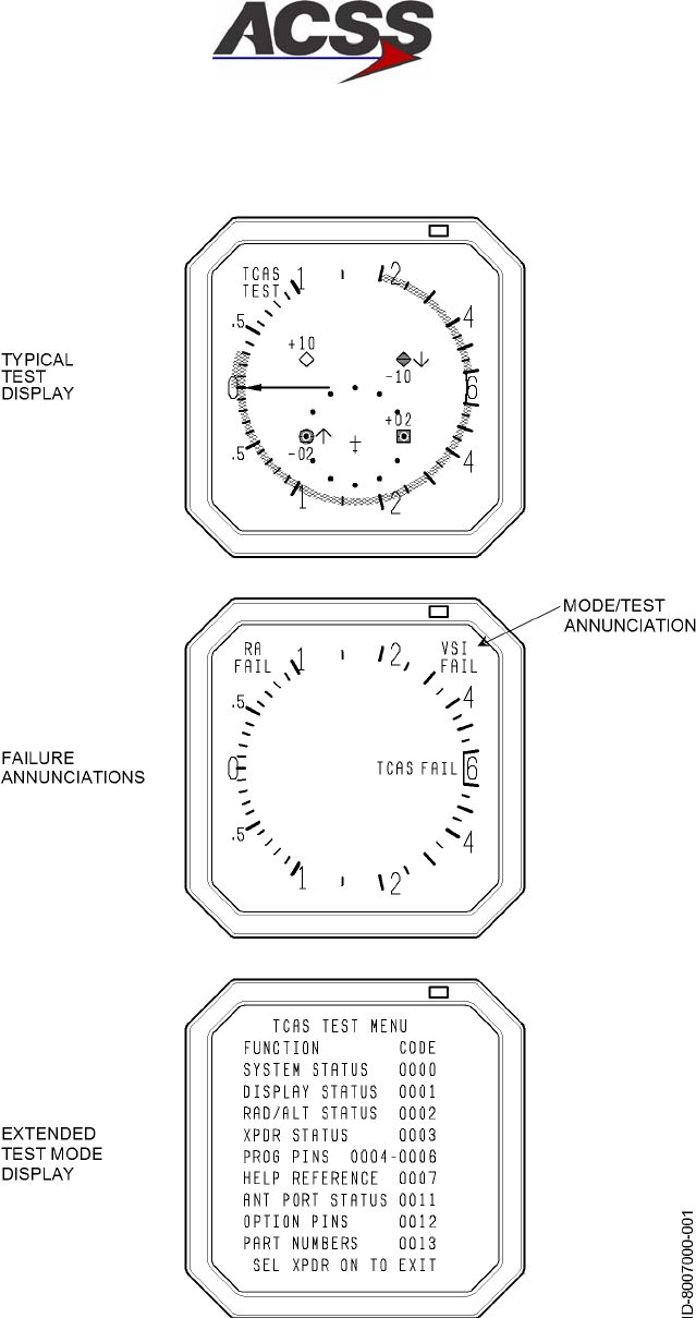
SYSTEM DESCRIPTION AND INSTALLATION MANUAL
TCAS 3000 Traffic Alert and Collision Avoidance System
34−43−23
Use or disclosure of information on this page is subject to the restrictions in the proprietary notice of this document.
Page 1−35
15 Dec 2005
Figure 1−12. Typical VSI/TRA Display Formats

SYSTEM DESCRIPTION AND INSTALLATION MANUAL
TCAS 3000 Traffic Alert and Collision Avoidance System
34−43−23
Use or disclosure of information on this page is subject to the restrictions in the proprietary notice of this document.
Page 1−36
15 Dec 2005
Table 1−9. VSI/TRA Leading Particulars
Item Specification
Dimensions (maximum):
•Height . . . . . . . . . . . . . . . . . . . . . . . . . . . . . . . . . . . . . . . 3.26 in. (82.8 mm)
•Width . . . . . . . . . . . . . . . . . . . . . . . . . . . . . . . . . . . . . . . . 3.26 in. (82.8 mm)
•Length . . . . . . . . . . . . . . . . . . . . . . . . . . . . . . . . . . . . . . . 9.42 in. (239.3 mm)
Weight (maximum) . . . . . . . . . . . . . . . . . . . . . . . . . . . . . . 4.0 lb (1.81 kg)
Power Requirements:
•Primary . . . . . . . . . . . . . . . . . . . . . . . . . . . . . . . . . . . . . . 115 V, 400 Hz; 18 Watts nominal,
31 Watts maximum
•External Circuit Breaker Rating . . . . . . . . . . . . . . . . . . 1 Amp at 115 V ac
Display Type . . . . . . . . . . . . . . . . . . . . . . . . . . . . . . . . . . . . Liquid Crystal
Mating Connectors:
•J1 (41 Pin Version) . . . . . . . . . . . . . . . . . . . . . . . . . . . . M83723/75R−20−41N
•J1 (55 Pin Version) . . . . . . . . . . . . . . . . . . . . . . . . . . . . M83723/75R−22−55N
Mounting . . . . . . . . . . . . . . . . . . . . . . . . . . . . . . . . . . . . . . . 3−ATI Clamp, Marmon NH1004994−30
or MSP 64311B
Environmental Specifications (DO−160B) . . . . . . . . . . . (A2F1)AKXXXXXXAEAEZZZK
(1) Functional Description and Operation
The VSI/TRA has three functions. It continuously displays rate of climb or rate of
descent. Traffic information is displayed and resolution advisory information is
displayed against vertical speed to allow the flight crew to avoid threats.
The vertical speed display is generated from signals applied directly to the indicator.
The VSI/TRA is designed to be used in place of a conventional vertical speed
indicator. Four possible sources exist for vertical speed data including ARINC 429
data, DC analog signals in accordance with ARINC 575 (approximately 500 mV per
1000 ft/min), ac analog signals in accordance with ARINC 565 (approximately 250
mV per 1000 ft/min), and ARINC 429 signals from the ACSS Pressure Transducer
Module. The VSI/TRA computes vertical rate from electrical static pressure when a
remote static sensor is used. These four program pin selectable configurations
provide compatibility with most aircraft.
Bootstrapping of vertical speed inputs as currently implemented on L−1011, A300,
A310 and A300−600 aircraft, is provided with a larger 55−pin unit connector. These
units have a unique dash number assigned to them.
Various dash number VSI/TRA Displays are available that provide unique design
characteristics, which include VSI rate filter programming and selection of an English
or metric rate scale. Table 1−5 contain a listing of all the VSI/TRA configurations.

SYSTEM DESCRIPTION AND INSTALLATION MANUAL
TCAS 3000 Traffic Alert and Collision Avoidance System
34−43−23
Use or disclosure of information on this page is subject to the restrictions in the proprietary notice of this document.
Page 1−37
15 Dec 2005
The VSI/TRA also displays symbology corresponding to traffic in the vicinity of the
aircraft. Threat information is received from the TCAS Computer Unit on a dedicated
high−speed ARINC 429 bus. The display uses the bearing, altitude, and range data
for each threat to provide an indication of the proximity of the threat. Allowable
(nonilluminated or green illuminated bands) and prohibited (red illuminated bands)
vertical rates are displayed based on information received from the TCAS computer
unit. The VSI/TRA can be pin programmed to provide vertical speed data only,
vertical speed and resolution advisory data, or vertical speed, resolution advisory and
traffic advisory data. Display of the TCAS system fault status is provided on the
VSI/TRA in response to extended TCAS control panel TEST activation.
Display dimming is controlled from several inputs consisting of an internal light sensor
mounted on the bezel of the LRU, a remote light sensor, and the aircraft dimming
bus. The display is dimmed by varying the brightness of the LCD panel backlighting.
(2) Software Considerations
VSI/TRA software is developed to a DO−178A category of Level ll (essential). The
software continually monitors and displays vertical speed and TCAS information.
Output discretes supply user components with the status of the LRU. TCAS valid
indicates that the LRU is displaying valid TCAS information. On the 55−pin version,
VSI valid indicates that the LRU is displaying valid vertical speed information. This is
needed to support the bootstrap feature, which is exclusive to the 55−pin version of
the VSI/TRA display.
(3) Built−In Test Equipment (BITE) and Self−Test Capability
The LRU has input discretes that allow a calibration and test program to be run. This
mode allows the display to be adjusted and various diagnostic tests to be performed.
These tests and adjustments can only be done in a shop on a dedicated test fixture.
When the LRU application program is operating in the aircraft, the background loop
continuously monitors the power supply status, the ROM integrity, and the analog
range limits. A failure results in the setting of bad status output discretes. A cold
start will continuously be attempted until the LRU passes the built−in test. There is a
dedicated self−test input for both versions of the VSI/TRA Display. When this pin is
activated, the unit will display symbology that aids in the detection of unit faults.
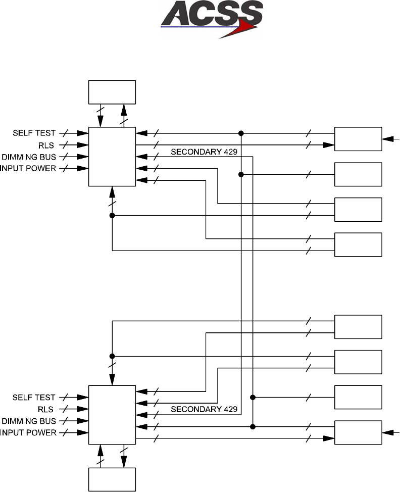
SYSTEM DESCRIPTION AND INSTALLATION MANUAL
TCAS 3000 Traffic Alert and Collision Avoidance System
34−43−23
Use or disclosure of information on this page is subject to the restrictions in the proprietary notice of this document.
Page 1−38
15 Dec 2005
TCAS CU
VSI/TRA
DISPLAY
#1
VSI/TRA
DISPLAY
#2
TCAS
CU
#1 PTM
DC ADC
#2
AC ADC
#2
DADC
#2
#2 PTM
1
2
ADC VALID
TA/RA
VALID
PRIMARY 429
PTM PWR
AC ADC
DC ADC
ADC VALID
DC ADC
AC ADC
ARINC 429
PTM PWR
ARINC 429
OR:
ARINC 565
VALID
VALID
OR:
OR:
41 PIN
VERSION
VALID
ARINC 575
VALID
ARINC 565
OR:
OR:
OR:
ARINC 429
PTM PWR
AD−53003@
PRIMARY 429
PTM PWR
2
2
2
2
2
3
3
1
1
2
2
3
3
1
1
1
1
2
3
3
3
2
2
2
1
1
2
1
3
3
2
2
3
#1 STATIC
PRESSURE
PORT
#2 STATIC
PRESSURE
PORT
3
TA/RA VALID
DC ADC
#1
AC ADC
#1
DADC
#1
ARINC 575 3
ARINC 429 2
Figure 1−13. VSI/TRA Interface Diagram (41−Pin Version)
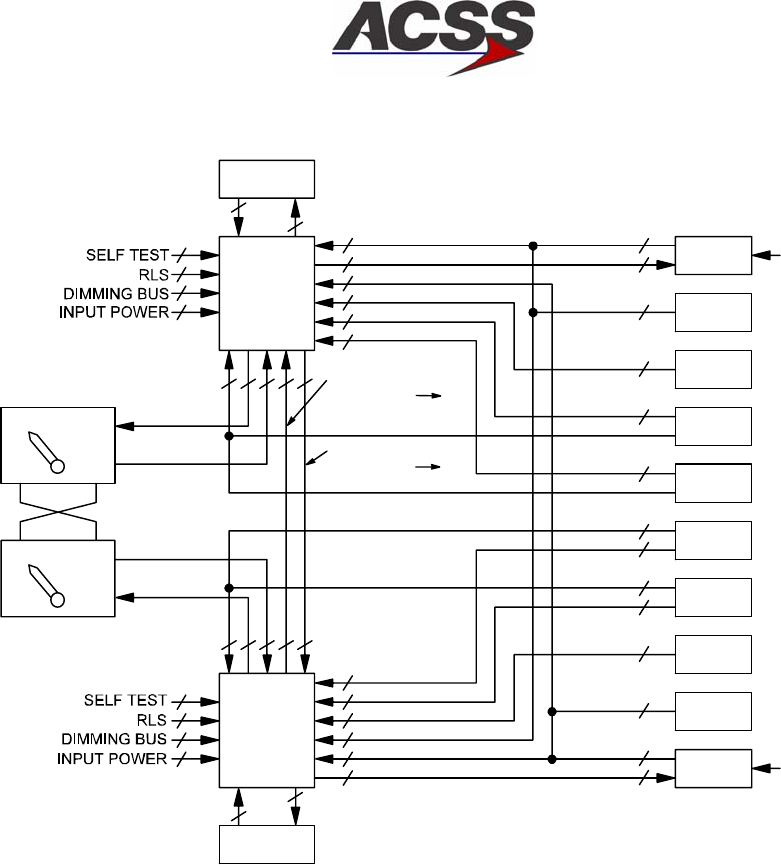
SYSTEM DESCRIPTION AND INSTALLATION MANUAL
TCAS 3000 Traffic Alert and Collision Avoidance System
34−43−23
Use or disclosure of information on this page is subject to the restrictions in the proprietary notice of this document.
Page 1−39
15 Dec 2005
TCAS CU
VSI/TRA
DISPLAY
#1
1
2
2
2
2
2
2
2
3
1
TCAS CU
VSI/TRA
DISPLAY
#2
1
2
2
2
2
2
2
#1 PTM
DADC
#1
AC ADC
#1
DC ADC
#1
ARINC 429
PTM PWR
ARINC 429
OR:
ARINC 565
VALID
VALID
OR:
OR:
2
2
3
3
1
1
#1 STATIC
PRESSURE
PORT
AND/OR:
IRS
#1
#2 PTM
ARINC 429
PTM PWR
2
3#2 STATIC
PRESSURE
PORT
DADC
#2
ARINC 429 2
IRS
#2
AC ADC
#2
DC ADC
#2
NORM ALT
NORM ALT
SOURCE
SOURCE
PRIMARY 429
PTM PWR
SECONDARY 429
IRS
AC ADC
DC ADC
3
3
3
DC ADC
AC ADC
IRS
SECONDARY 429
PRIMARY 429
PTM PWR
21TA/RA
VALID
2
1144
2
1144
ADC VALID
BS CMD
BS CMD
ADC VALID
#1 BOOTSTRAP
MANUAL
CONTROLLER
#2 BOOTSTRAP
MANUAL
CONTROLLER
55 PIN
VERSION
(W/BOOTSTRAP)
AD−53004@
OR:
OR:
OR:
AND/OR:
3
3
ARINC 575 3
ARINC 565 3
ARINC 429 2
VALID 1
VALID 1
BOOTSTRAP VS
SIGNAL #2 #1
BOOTSTRAP VS
SIGNAL #1 #2
SELECT
SELECT
ARINC 429 2
ARINC 575 3
Figure 1−14. VSI/TRA Interface Diagram (55−Pin Version)
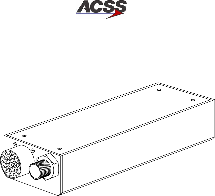
SYSTEM DESCRIPTION AND INSTALLATION MANUAL
TCAS 3000 Traffic Alert and Collision Avoidance System
34−43−23
Use or disclosure of information on this page is subject to the restrictions in the proprietary notice of this document.
Page 1−40
15 Dec 2005
F. Pressure Transducer Module
The Pressure Transducer Module (PTM) converts static pressure to a low speed ARINC
429 signal used by the VSI/TRA to calculate altitude rate. Figure 1−15 shows a graphical
view of the PTM. The PTM can be mounted in any pressurized area of the aircraft.
Table 1−10 gives items and specifications particular to the unit.
AD−53005@
Figure 1−15. Pressure Transducer Module

SYSTEM DESCRIPTION AND INSTALLATION MANUAL
TCAS 3000 Traffic Alert and Collision Avoidance System
34−43−23
Use or disclosure of information on this page is subject to the restrictions in the proprietary notice of this document.
Page 1−41
15 Dec 2005
Table 1−10. Pressure Transducer Module Leading Particulars
Item Specification
Dimensions (maximum):
•Height . . . . . . . . . . . . . . . . . . . . . . . . . . . . . . . . . . . . . . . 1.6 in. (40.6 mm)
•Width . . . . . . . . . . . . . . . . . . . . . . . . . . . . . . . . . . . . . . . . 2.8 in. (71.1 mm)
•Length . . . . . . . . . . . . . . . . . . . . . . . . . . . . . . . . . . . . . . . 7.5 in. (190.5 mm)
Weight (maximum) . . . . . . . . . . . . . . . . . . . . . . . . . . . . . . 2.0 lb (0.091 kg)
Power Requirements . . . . . . . . . . . . . . . . . . . . . . . . . . . . ±12 V DC derived from VSI/TRA ±15 V
power supply
Power Consumption . . . . . . . . . . . . . . . . . . . . . . . . . . . . . 2.0 Watts nominal
Mating Connectors:
•J1 (Electrical Connector) . . . . . . . . . . . . . . . . . . . . . . . 15 Pin Round, M83723/75A1415N
•(Pneumatic Fitting) . . . . . . . . . . . . . . . . . . . . . . . . . . . . Flareless nipple, NAS 1760−06
Mounting . . . . . . . . . . . . . . . . . . . . . . . . . . . . . . . . . . . . . . . A mounting bracket is available for use
in a limited access area or an ARINC
408A 3−ATI round plate is available for
mounting in the instrument panel
The PTM contains a pressure sensor packaged in a TO−8 header case and measures by
a strain gage mechanism. The pressure sensor converts pressure that range from 3.0 to
33.0 inHg into a differential output voltage. Contained within the sensor are the strain
sensing element, sensor heater, and temperature sensing diode.
The PTM meets the specifications that follow after the altitude rate has been calculated
from the static pressure source:
•The input pressure range is from 3.0 to 33.0 inHg, which covers the altitude range of
−2,000 to +50,000 feet
•The applied altitude rate ranges from 0 to ±6000 ft/min
•The PTM is capable of detecting and input pressure variation of 25 ft/min
•The PTM is capable of tracking input signals of 40 ft/sec without performance
degradation.
The PTM is designed to send a power down message to the VSI/TRA. This is the only
BITE capability of this unit.
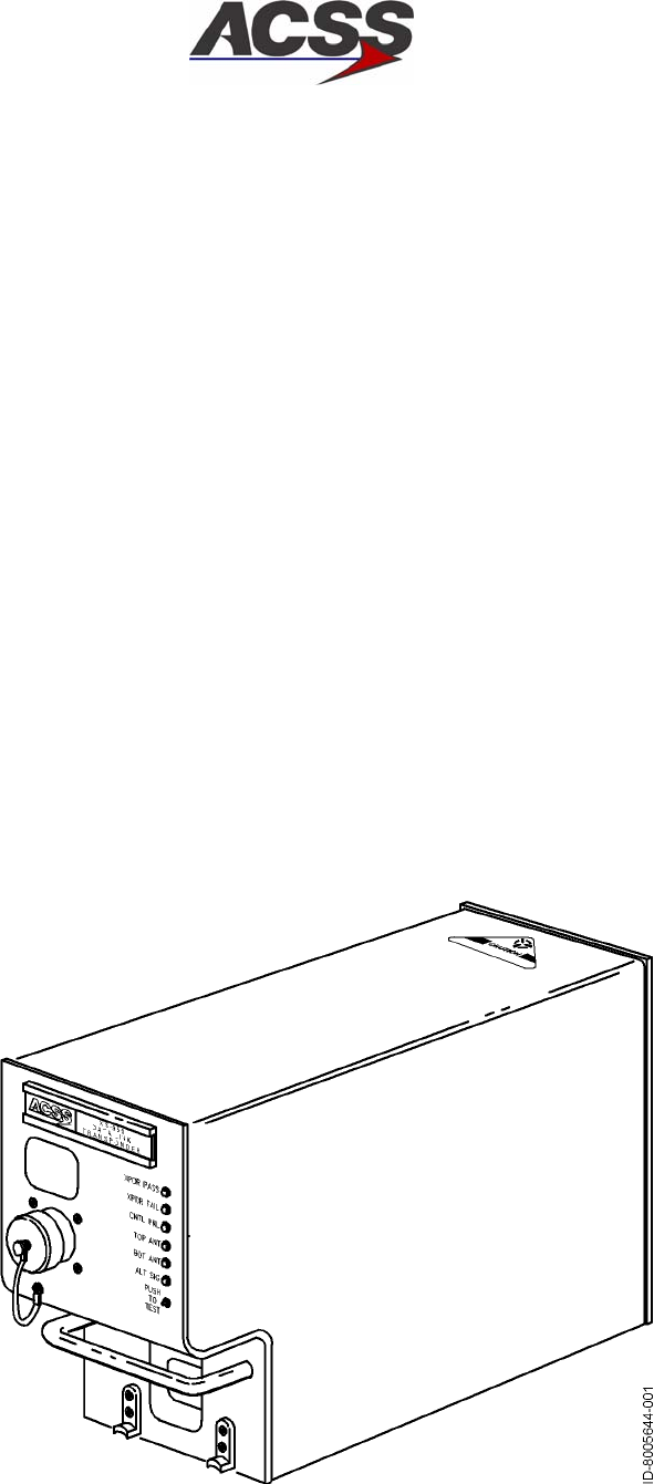
SYSTEM DESCRIPTION AND INSTALLATION MANUAL
TCAS 3000 Traffic Alert and Collision Avoidance System
34−43−23
Use or disclosure of information on this page is subject to the restrictions in the proprietary notice of this document.
Page 1−42
15 Dec 2005
G. XS−950 Mode S Data Link Transponder
The XS−950 Data Link Transponder provides surveillance functions to ground based and
airborne interrogators, and communication functions to various onboard systems. The
transponder contains data link functions that allow it to function as part of the Aircraft
Telecommunications Network (ATN). The data link functions allow communication with a
Communication Management Unit (CMU) through a Mode S Airborne Data Link
Processor (ADLP). The transponder also contains Mode S specific functions that are
dedicated links to onboard systems. The XS−950 Transponder has the capability to be
upgraded to provide an internal airborne data link processor (ADLP) function.
The XS−950 Transponder conforms to the ARINC 718−A Mode S Transponder
Characteristic for form, fit and function, and is backward compatible with existing ARINC
718−A installations. It is certified to ICAO level IV data link capability and can be
upgraded to level V data link capability.
The XS−950 Data Link Transponder is packaged in a 4−MCU (Modular Concept Unit)
outline as defined in ARINC Characteristic 600−7. The unit is able to utilize ARINC 404
cooling air moving through the LRU in a downward direction as well as ARINC 600
cooling air moving through the LRU in an upward direction. The rear connector
receptacle is an ARINC 600 size 2 shell assembly with inserts and contacts as defined in
ARINC Characteristic 718−A. The unit also features a fixed carrying handle and self−test
button with discrete LRU STATUS annunciators.
Figure 1−16 shows a graphical view of the XS−950 Data Link Transponder and
Table 1−11 gives items and specifications that are particular to the transponder.
Figure 1−16. XS−950 Data Link Transponder

SYSTEM DESCRIPTION AND INSTALLATION MANUAL
TCAS 3000 Traffic Alert and Collision Avoidance System
34−43−23
Use or disclosure of information on this page is subject to the restrictions in the proprietary notice of this document.
Page 1−43
15 Dec 2005
Table 1−11. XS−950 Data Link Transponder Leading Particulars
Item Specification
Dimensions (maximum):
•Height . . . . . . . . . . . . . . . . . . . . . . . . . . . . . . . . . . . . . . 7.6 in. (192 mm)
•Width . . . . . . . . . . . . . . . . . . . . . . . . . . . . . . . . . . . . . . 4.9 in. (124.5 mm)
•Length . . . . . . . . . . . . . . . . . . . . . . . . . . . . . . . . . . . . . 15.2 in. (386 mm)
Weight . . . . . . . . . . . . . . . . . . . . . . . . . . . . . . . . . . . . . . . 11.5 lb (5.2 kg)
Power Requirements (115 V ac version):
•Operating Voltage . . . . . . . . . . . . . . . . . . . . . . . . . . . . 97 to 134 V rms, 115 V rms nominal
•Operating Frequency . . . . . . . . . . . . . . . . . . . . . . . . . 320 to 480 Hz, 400 Hz nominal
•Power Consumption:
− Standby Mode (No Replies) . . . . . . . . . . . . . . . . . 40 Watts maximum
− Active mode (Maximum Load) . . . . . . . . . . . . . . . 85 Watts maximum
•External Circuit Breaker Rating . . . . . . . . . . . . . . . . . 5 A at 115 V ac, 400 Hz
Power Requirements (28 V dc version):
•Operating Voltage . . . . . . . . . . . . . . . . . . . . . . . . . . . . +18.0 to +32.2 V dc, +27.5 V dc nominal
•Power Consumption:
−Standby Mode (No Replies) . . . . . . . . . . . . . . . . . 40 Watts maximum
−Active mode (Maximum Load) . . . . . . . . . . . . . . . 85 Watts maximum
•External Circuit Breaker Rating . . . . . . . . . . . . . . . . . 7 A at 28 V dc
Mating Connector . . . . . . . . . . . . . . . . . . . . . . . . . . . . . . Radial Part No. NSXN2P203X0005
Mounting . . . . . . . . . . . . . . . . . . . . . . . . . . . . . . . . . . . . . . ARINC 600 4MCU Tray Assembly
TSO . . . . . . . . . . . . . . . . . . . . . . . . . . . . . . . . . . . . . . . . . . C112, CL043, 121, F11
Environmental Specifications: . . . . . . . . . . . . . . . . . . . . DO−160C Environmental Category
−115 V ac version . . . . . . . . . . . . . . . . . . . . . . . . . . . [A2E1]−BB[CLMY]XXXXXXZEAEZRZA3E3XX
−28 V dc version . . . . . . . . . . . . . . . . . . . . . . . . . . . [A2E1]−BB[CLMY]XXXXXXZ[BZ]AZZRZA3E3XX
•Temperature / Altitude [A2E1]:
−Operating Temperature . . . . . . . . . . . . . . . . . . . . . −55 to +70 degrees C
−Ground Survival Temperature . . . . . . . . . . . . . . . −55 to +85 degrees C
−Altitude . . . . . . . . . . . . . . . . . . . . . . . . . . . . . . . . . . . Sea Level to 70,000 feet
−Loss of Cooling . . . . . . . . . . . . . . . . . . . . . . . . . . . . +40 degrees C for 30 minutes minimum

SYSTEM DESCRIPTION AND INSTALLATION MANUAL
TCAS 3000 Traffic Alert and Collision Avoidance System
34−43−23
Use or disclosure of information on this page is subject to the restrictions in the proprietary notice of this document.
Page 1−44
15 Dec 2005
Table 1−11. XS−950 Data Link Transponder Leading Particulars(cont)
Item Specification
•Vibration [CLMY]:
− Category C . . . . . . . . . . . . . . . . . . . . . . . . . . . . . . . Fixed wing turbojet engine, fuselage mounting
− Category L . . . . . . . . . . . . . . . . . . . . . . . . . . . . . . . Fixed wing reciprocating and turboprop multi and
single engine over 12,500 pounds, fuselage
mounting
− Category M . . . . . . . . . . . . . . . . . . . . . . . . . . . . . . . Fixed wing reciprocating and turboprop multi and
single engine less than 12,500 pounds, instrument
panel/console and equipment rack mounting
− Category Y . . . . . . . . . . . . . . . . . . . . . . . . . . . . . . . Helicopter, reciprocating and turbojet, fuselage
mounting
Operating Modes:
•STANDBY . . . . . . . . . . . . . . . . . . . . . . . . . . . . . . . . . . . Ready but not replying
•ATC ON . . . . . . . . . . . . . . . . . . . . . . . . . . . . . . . . . . . . Transponder Modes A and S, no altitude reporting
•ATC ALT . . . . . . . . . . . . . . . . . . . . . . . . . . . . . . . . . . . Transponder Modes A, C, and S. Altitude reporting
is enabled
Transmitter Frequency . . . . . . . . . . . . . . . . . . . . . . . . . 1090 ±1.0 MHz
Transmitter Power . . . . . . . . . . . . . . . . . . . . . . . . . . . . . 640 Watts maximum peak pulse, 250 Watts
minimum
Receiver Frequency . . . . . . . . . . . . . . . . . . . . . . . . . . . . 1030 MHz
Minimum Trigger Level (MTL) . . . . . . . . . . . . . . . . . . . . −76 ± 3 dBm
Mutual Suppression . . . . . . . . . . . . . . . . . . . . . . . . . . . . Bidirectional, accepts +18 to +70 volt pulse input;
provides +28 volt nominal output
Controller Interface:
•Circuit Configuration . . . . . . . . . . . . . . . . . . . . . . . . . . Two ARINC 429 control data input ports. 12.5 K
bits/s (low−speed ARINC)
•Bus Protocol . . . . . . . . . . . . . . . . . . . . . . . . . . . . . . . . . Bus protocol meets requirements defined in ARINC
718−A for receiving transponder and TCAS control
information.
TCAS II Interface:
•Circuit Configuration . . . . . . . . . . . . . . . . . . . . . . . . . . ARINC 429 input and output bus. 100 K bits/s
(high−speed ARINC)
•Bus Protocol . . . . . . . . . . . . . . . . . . . . . . . . . . . . . . . . . Bus protocol meets requirements defined in ARINC
718−A and ARINC 735A−1 for standard transponder
to TCAS interface

SYSTEM DESCRIPTION AND INSTALLATION MANUAL
TCAS 3000 Traffic Alert and Collision Avoidance System
34−43−23
Use or disclosure of information on this page is subject to the restrictions in the proprietary notice of this document.
Page 1−45
15 Dec 2005
Table 1−11. XS−950 Data Link Transponder Leading Particulars(cont)
Item Specification
Airborne Data Link Processor (ADLP) Interface:
•Circuit Configuration . . . . . . . . . . . . . . . . . . . . . . . . . . COMM−A/B messages have an ARINC 429 input
and output bus.
COMM−C/D messages have an ARINC 429 input
and output bus.
Both sets of busses are 100 K bits/s (high−speed
ARINC).
•Bus Protocol . . . . . . . . . . . . . . . . . . . . . . . . . . . . . . . . . Bus protocol meets requirements defined in ARINC
718−A for standard transponder to ADLP bus
interface.
Altimeter Interface:
•Digital Air Data . . . . . . . . . . . . . . . . . . . . . . . . . . . . . . . ARINC 429 or 575 data format. 12.5 K bits/s
(low−speed ARINC). Two altimeter inputs (left and
right altimeters).
•Synchro Altitude . . . . . . . . . . . . . . . . . . . . . . . . . . . . . ARINC 407 data format. Fine and course 3−wire
synchro inputs and a synchro valid flag discrete
input. Two sets of synchro altimeter inputs (left and
right altimeters).
•Analog Altitude (−20012, −65012 Only) . . . . . . . . . . Three wire proportional input with valid flag discrete
input. Two altimeter inputs (left and right altimeters).
Discrete input to enable altitude comparison.
•Encoding Altimeter . . . . . . . . . . . . . . . . . . . . . . . . . . . Gillham altitude data format. 11−wire discrete input.
Two altimeter inputs (left and right altimeters).
•Altitude Selection . . . . . . . . . . . . . . . . . . . . . . . . . . . . . Altitude source (left and right) selected by discrete
input.
Airframe Parameter Data Interface:
•Circuit Configuration . . . . . . . . . . . . . . . . . . . . . . . . . . ARINC 429 input busses. High (100K bits/s) or Low
(12.5 K bits/s). Speed, auto−detected by
transponder.
•Bus Protocol . . . . . . . . . . . . . . . . . . . . . . . . . . . . . . . . . Aircraft parameters required to support Elementary
and Enhanced Surveillance (ELS/EHS) as well as
Extended Squitter. Bus protocal and input ports as
defined in ARINC 718−A, minimum subset..
Aircraft Air/Ground Status Interface . . . . . . . . . . . . . . . Two discrete inputs used to indicate the aircraft
air/ground status.
Maintenance Computer Interface:
•Circuit Configuration . . . . . . . . . . . . . . . . . . . . . . . . . . ARINC 429 input and output bus. 12.5 K bits/s
(low−speed ARINC).

SYSTEM DESCRIPTION AND INSTALLATION MANUAL
TCAS 3000 Traffic Alert and Collision Avoidance System
34−43−23
Use or disclosure of information on this page is subject to the restrictions in the proprietary notice of this document.
Page 1−46
15 Dec 2005
Table 1−11. XS−950 Data Link Transponder Leading Particulars(cont)
Item Specification
•Bus Protocol . . . . . . . . . . . . . . . . . . . . . . . . . . . . . . . . . The maintenance computer interface meets protocol
requirements for all model Airbus, Boeing, and
McDonnell Douglas maintenance computers.
Onboard Software Uploading / Maintenance Log
Downloading:
•Circuit Configuration . . . . . . . . . . . . . . . . . . . . . . . . . . Portable Data Loader thru ARINC 615 Front Panel
Connector
ARINC 429 input and output bus (100 K bits/s) PDL
Link A discrete input
RS−232 input/output bus (38.4 K bits/s) at 53−pin
PDL connector
Airborne Data Loader thru Unit Rear Connector
ARINC 429 input and output bus (100 K bits/s) ADL
Link A discrete input
•Bus Protocol . . . . . . . . . . . . . . . . . . . . . . . . . . . . . . . . . Software uploads thru ARINC 429 PDL (front panel)
port or ARINC 429 ADL (rear connector) port per the
protocol in ARINC 615 high−speed data loader
Maintenance log downloads thru ARINC 429 PDL
port or ARINC 429 ADL port per the protocol in
ARINC 615 high−speed data loader
Software uploads and maintenance log downloads
can be accomplished through the PDL front panel
port with an RS−232 interface bus and a PC with
terminal emulation software

SYSTEM DESCRIPTION AND INSTALLATION MANUAL
TCAS 3000 Traffic Alert and Collision Avoidance System
34−43−23
Use or disclosure of information on this page is subject to the restrictions in the proprietary notice of this document.
Page 1−47
15 Dec 2005
H. RCZ−852 Diversity Mode S Transponder
The RCZ−852 Diversity Mode S Transponder is an airborne transponder designed to
perform both conventional and advanced air traffic control (ATC) functions. It receives
coded radar signals from ATC ground stations and other aircraft and transmits coded
replies. The replies contain information such as aircraft identity, altitude, and data
communication messages.
The transponder works with the air traffic control radar beacon system (ATCRBS) and
mode select (Mode S) system to provide enhanced surveillance and communications
capability required for air traffic control system automation and onboard collision
avoidance systems. It has antenna diversity and is defined as a Class 3A transponder
with TCAS interface capability. The RCZ−852 Diversity Mode S Transponder has the
capabilities that follow:
•Surveillance functions of both ATCRBS and Mode S ground sensors
•Surveillance functions of airborne interrogators
•Bi−directional air−to−air information exchanges, COMM−U/V
•Ground−to−Air data uplink, COMM−A
•Air−to−Ground data downlink, COMM−B
•Multisite message protocol
•Ground−to−Air extended length message (ELM), COMM−C.
The transponder does not support COMM−D extended length message (ELM)
communication.
Figure 1−17 shows a graphical view of the RCZ−852 Diversity Mode S Transponder and
Table 1−12 gives items and specifications that are particular to the transponder.
Figure 1−17. RCZ−852 Diversity Mode S Transponder

SYSTEM DESCRIPTION AND INSTALLATION MANUAL
TCAS 3000 Traffic Alert and Collision Avoidance System
34−43−23
Use or disclosure of information on this page is subject to the restrictions in the proprietary notice of this document.
Page 1−48
15 Dec 2005
Table 1−12. RCZ−852 Diversity Mode S Transponder Leading Particulars
Item Specification
Dimensions (maximum):
•Height . . . . . . . . . . . . . . . . . . . . . . . . . . . . . . . . . . . . . . 3.38 in. (86 mm)
•Width . . . . . . . . . . . . . . . . . . . . . . . . . . . . . . . . . . . . . . 4.10 in. (104 mm)
•Length . . . . . . . . . . . . . . . . . . . . . . . . . . . . . . . . . . . . . 14.1 in. (358 mm)
Weight . . . . . . . . . . . . . . . . . . . . . . . . . . . . . . . . . . . . . . . 5.0 lb (2.27 kg)
Power Requirements:
•Operating Voltage . . . . . . . . . . . . . . . . . . . . . . . . . . . . +18.0 to +30.3 V dc, +27.5 V dc nominal
•Power Consumption:
− Standby Mode (No Replies) . . . . . . . . . . . . . . . . . 28 Watts nominal
− Active Mode (Maximum Load) . . . . . . . . . . . . . . . 55 Watts maximum
•External Circuit Breaker Rating . . . . . . . . . . . . . . . . . 5 A at +27.5 V dc
Mating Connector . . . . . . . . . . . . . . . . . . . . . . . . . . . . . . ACSS Part No. 7500294−106,
Tri−Star Part No. TRAP−106P−26(200);
Cannon Part No. DPXAMA−21000−2491
(Part of Installation Kit, ACSS Part No.
7510707−968)
Mounting . . . . . . . . . . . . . . . . . . . . . . . . . . . . . . . . . . . . . . Mount Assembly, ACSS Part No. 7517455−902
TSO . . . . . . . . . . . . . . . . . . . . . . . . . . . . . . . . . . . . . . . . . . C112
Environmental Specifications . . . . . . . . . . . . . . . . . . . . . DO−160B Environmental Category
/A2E1/B/JLMY/E1XXXXXZ/BZ/AZZ
•Temperature / Altitude [A2E1]:
−Operating Temperature . . . . . . . . . . . . . . . . . . . . . −55 to +70 degrees C
−Ground Survival Temperature . . . . . . . . . . . . . . . −55 to +85 degrees C
− Altitude . . . . . . . . . . . . . . . . . . . . . . . . . . . . . . . . . . . Sea Level to 70,000 feet
−Decompression . . . . . . . . . . . . . . . . . . . . . . . . . . . . 8,000 to 70,000 feet
− Overpressure . . . . . . . . . . . . . . . . . . . . . . . . . . . . . −15,000 feet
•Vibration [JLMY]:
− Category J . . . . . . . . . . . . . . . . . . . . . . . . . . . . . . . Fixed wing turbojet, subsonic and supersonic,
fuselage mounting
− Category L . . . . . . . . . . . . . . . . . . . . . . . . . . . . . . . Fixed wing reciprocating and turboprop multi and
single engine over 12,500 pounds, fuselage
mounting

SYSTEM DESCRIPTION AND INSTALLATION MANUAL
TCAS 3000 Traffic Alert and Collision Avoidance System
34−43−23
Use or disclosure of information on this page is subject to the restrictions in the proprietary notice of this document.
Page 1−49
15 Dec 2005
Table 1−12. RCZ−852 Diversity Mode S Transponder Leading Particulars (cont)
Item Specification
− Category M . . . . . . . . . . . . . . . . . . . . . . . . . . . . . . . Fixed wing reciprocating and turboprop multi and
single engine less than 12,500 pounds, instrument
panel/console and equipment rack mounting
− Category Y . . . . . . . . . . . . . . . . . . . . . . . . . . . . . . . Helicopter, reciprocating and turbojet, fuselage
mounting
Operating Modes:
•STANDBY . . . . . . . . . . . . . . . . . . . . . . . . . . . . . . . . . . . Ready but not replying.
•ATC ON . . . . . . . . . . . . . . . . . . . . . . . . . . . . . . . . . . . . Transponder Modes A and S. No altitude reporting.
•ATC ALT . . . . . . . . . . . . . . . . . . . . . . . . . . . . . . . . . . . Transponder Modes A, C, and S. Altitude reporting
is enabled.
Transmitter Frequency . . . . . . . . . . . . . . . . . . . . . . . . . 1090 ±0.5 MHz
Transmitter Power . . . . . . . . . . . . . . . . . . . . . . . . . . . . . 500 Watts peak pulse, 250 Watts minimum
Receiver Frequency . . . . . . . . . . . . . . . . . . . . . . . . . . . . 1030 MHz
Minimum Trigger Level (MTL) . . . . . . . . . . . . . . . . . . . . −77 ± 3 dBm
Mutual Suppression . . . . . . . . . . . . . . . . . . . . . . . . . . . . Bidirectional, accepts +18 to +70 volt pulse input,
provides +28 volt nominal output
Controller interface:
•Circuit Configuration . . . . . . . . . . . . . . . . . . . . . . . . . . Two ARINC 429 control data input ports. 12.5 K
bits/s (low−speed ARINC)
•Bus Protocol . . . . . . . . . . . . . . . . . . . . . . . . . . . . . . . . . Bus protocol meets requirements defined in ARINC
718−A for receiving transponder and TCAS control
information.
TCAS II Interface:
•Circuit Configuration . . . . . . . . . . . . . . . . . . . . . . . . . . ARINC 429 input and output bus. 100 K bits/s
(high−speed ARINC).
•Bus Protocol . . . . . . . . . . . . . . . . . . . . . . . . . . . . . . . . . Bus protocol meets requirements defined in ARINC
718−A and ARINC 735 for standard transponder to
TCAS interface.
Airborne Data Link Processor (ADLP) Interface:
•Circuit Configuration . . . . . . . . . . . . . . . . . . . . . . . . . . COMM−A/B messages have an ARINC 429 input
and output bus.
COMM−C/D messages have an ARINC 429 input
and output bus.
Both sets of busses are 100 K bits/s (high−speed
ARINC).
•Bus Protocol . . . . . . . . . . . . . . . . . . . . . . . . . . . . . . . . . Bus protocol meets requirements defined in ARINC
718−A for standard transponder to ADLP bus
interface.

SYSTEM DESCRIPTION AND INSTALLATION MANUAL
TCAS 3000 Traffic Alert and Collision Avoidance System
34−43−23
Use or disclosure of information on this page is subject to the restrictions in the proprietary notice of this document.
Page 1−50
15 Dec 2005
Table 1−12. RCZ−852 Diversity Mode S Transponder Leading Particulars (cont)
Item Specification
•Exception . . . . . . . . . . . . . . . . . . . . . . . . . . . . . . . . . . . COMM−D messages are not processed by this
transponder.
Altimeter Interface:
•Digital Air Data . . . . . . . . . . . . . . . . . . . . . . . . . . . . . . . ARINC 429 or 575 data format. 12.5 K bits/s
(low−speed ARINC). Two altimeter inputs (left and
right altimeters).
•IAC Air Data . . . . . . . . . . . . . . . . . . . . . . . . . . . . . . . . . Radio System Bus (RSB) interface supplies the
Honeywell Integrated Avionics Computer (IAC)
digital air data information. Two altimeter inputs (left
and right altimeters).
•Encoding Altimeter . . . . . . . . . . . . . . . . . . . . . . . . . . . Gillham altitude data format. 11−wire discrete input.
Two altimeter inputs (left and right altimeters).
•Altitude Selection . . . . . . . . . . . . . . . . . . . . . . . . . . . . . Altitude source (left or right) selected by a discrete
input.
Flight Identifier Interface:
•From Radio Management (RMU) . . . . . . . . . . . . . . . Flight identifier input from the RMU in RSB data
format.
•From Flight Management System (FMS) . . . . . . . . Flight identifier input from the FMS in ARINC 429
data format. 12.5 K bits/s (low−speed ARINC).
Aircraft Air/Ground Status Interface . . . . . . . . . . . . . . . Two discrete inputs used to indicate the aircraft
air/ground status.
Antenna Selection Interface . . . . . . . . . . . . . . . . . . . . . . A discrete output supplies a GROUND when
transponder is active.
RCB Interface:
•Circuit Configuration . . . . . . . . . . . . . . . . . . . . . . . . . . 2−wire full duplex RS−232 serial link to/from internal
radio communications bus (RCB).
•Transmission Rate . . . . . . . . . . . . . . . . . . . . . . . . . . . 187.5 K baud
•Transmission Format . . . . . . . . . . . . . . . . . . . . . . . . . 1 start bit, 8 data bits and 1 stop bit
Shop Flash Memory Programming Interface:
•Circuit Configuration . . . . . . . . . . . . . . . . . . . . . . . . . . 2−wire full duplex RS−232 serial port
•Transmission Rate . . . . . . . . . . . . . . . . . . . . . . . . . . . 19.2 K baud
•Transmission Format . . . . . . . . . . . . . . . . . . . . . . . . . 1 start bit, 7 data bits, odd parity and 1 stop bit

SYSTEM DESCRIPTION AND INSTALLATION MANUAL
TCAS 3000 Traffic Alert and Collision Avoidance System
34−43−23
Use or disclosure of information on this page is subject to the restrictions in the proprietary notice of this document.
Page 1−51
15 Dec 2005
5. System Operation
The principal modes of operation and display features of the TCAS 3000 are discussed in the
paragraphs that follow. In−flight procedures with display examples are contained in the TCAS
Pilot’s Manual, ACSS Publication No. C28−3841−005.
A. Operational Modes
The TCAS 3000 can operate in several different modes, depending on control panel
selection. Several control panels are available. Only the ACSS single Mode S control
panel is discussed. Other control panels provide similar features.
Four switches directly affect the TCAS operational mode: TCAS/XPDR mode selector, TA
DSPLY selector, ALT RPTG selector, and TCAS TEST switch. To distinguish the modes
that provide TCAS advisories from those that do not, the operational modes are
discussed under TCAS modes and non−TCAS modes. The non−TCAS modes are
annunciated TCAS OFF at the center of the display.
The extended test mode is mentioned for reference. A detailed description of its use can
be found in the FAULT ISOLATION section.
(1) TCAS Modes
The TA/RA and the TA−only modes are the two TCAS operational modes. The
TA/RA mode gives traffic information and warnings of hazardous traffic conflicts,
while the TA mode gives only traffic information. A third mode, the TEST mode, can
be temporarily activated from any mode including standby (STBY). The TEST mode
does not inhibit the generation of advisories. Functions available in the operational
and test modes are as follows:
(a) TA/RA Mode
This mode is the normal operation mode providing full TCAS coverage. In this
mode, TCAS tracks all aircraft in the surrounding airspace and generates traffic
advisories or resolution advisories, as the situation requires. Figure 1−3
contrasts the airspace covered for each kind of advisory.
For normal TA/RA operation, the TA/DSPLY selector must be set to AUTO or ON
and the ALT/RPTG selector must be set to 1 or 2.
(b) TA Mode
The TA mode provides only surveillance of the surrounding airspace. In this
mode, TCAS tracks all proximate aircraft and generates traffic advisories; no
resolution advisories are issued in this mode.
The flight crew uses the TA−only mode when resolution advisories would be a
nuisance, or when flying over an area where only TCAS surveillance is allowed.
Also, the system automatically selects this mode when the aircraft is flying under
1000 feet above ground level (AGL).
The TA mode is annunciated TA ONLY at the upper left corner of the display.

SYSTEM DESCRIPTION AND INSTALLATION MANUAL
TCAS 3000 Traffic Alert and Collision Avoidance System
34−43−23
Use or disclosure of information on this page is subject to the restrictions in the proprietary notice of this document.
Page 1−52
15 Dec 2005
(c) Test Mode
Pushing the TEST button on the control panel starts a self−test program which
verifies proper operation of the TA and RA displays and of the aural advisories
on the audio system.
The test mode does not affect normal TCAS operation, provided the selected
transponder remains in normal operation during the test cycle. Should a TA or
RA occur during the test sequence, the test aborts, and the advisory is
announced and displayed.
The test mode just described excludes extended self−tests performed on the
ground, where TCAS is inoperative.
(2) Non−TCAS Modes
The control panel selections that follow disable TCAS operation and all advisories:
•MODE S ON activates a Mode S transponder only
•STBY sets the selected transponder in standby mode
•ATC activates an ATCRBS transponder only
•ALT RPTG set to OFF inhibits altitude reporting.
When TCAS is inoperative as a result of control panel selection, TCAS OFF is
annunciated on the display. When TCAS is inoperative due to a system failure, TA
FAIL, RA FAIL, or TCAS FAIL is annunciated on the display. In addition, if the
transponder or the altitude data source fails, the XPDR FAIL light on the control panel
comes on.
(3) Extended Test Mode
The purpose of the extended test mode is to facilitate diagnosis in the event
self−test has failed. Like self−test, this mode is enabled by pushing the TCAS TEST
button, but only when TCAS is inoperative. The aircraft must be on the ground, and
the transponder must be set to STBY. Holding TCAS TEST pushed for longer than
eight seconds in this condition activates the extended tests. This feature is not
available on all systems. Refer to the TESTING AND FAULT ISOLATION section for
system requirements and test description.
SYSTEM DESCRIPTION AND INSTALLATION MANUAL
TCAS 3000 Traffic Alert and Collision Avoidance System
34−43−23
Use or disclosure of information on this page is subject to the restrictions in the proprietary notice of this document.
Page 1−53
15 Dec 2005
B. Display Symbology
The TCAS modes use color−coded symbols and data tags to map air traffic and locate
threat aircraft on the VSI/TRA display.
Four traffic symbols are used: solid circle, solid square, solid diamond, and hollow
diamond. See Figure 1−18 for examples. A different color is assigned to each symbol
type, as listed in Table 1−13.
Table 1−13. TCAS Traffic Symbols
Graphic Symbol Color Display Function
Solid Circle Amber Traffic Advisory (TA)
Solid Square Red Resolution Advisory (RA)
Solid Diamond Blue Proximate Traffic
Hollow Diamond Blue Other Traffic
NOTE: TCAS traffic information displayed on EFIS displays such as crew alerting
system display, navigation display, electronic horizontal situation display or
multifunction display, is similar to that on combined VSI/TRA indicators. Traffic
symbology is identical to that displayed on the VSI/TRA.
(1) Colors
(a) Amber
Represents a moderate threat to a TCAS−equipped aircraft. A visual search is
recommended to prepare for intruder avoidance. Amber is used only in
conjunction with a traffic advisory.
(b) Red
Represents an immediate threat to a TCAS−equipped aircraft. Prompt action is
required to avoid the intruder. This color is only used in conjunction with a
resolution advisory.
(c) Blue
Represents proximate traffic and other traffic the TCAS surveillance logic has in
its track file.
(d) White
Used only for mode annunciations and for reference graphics, including aircraft
home position, range ring, and VSI scale.

SYSTEM DESCRIPTION AND INSTALLATION MANUAL
TCAS 3000 Traffic Alert and Collision Avoidance System
34−43−23
Use or disclosure of information on this page is subject to the restrictions in the proprietary notice of this document.
Page 1−54
15 Dec 2005
(2) Traffic Identification
(a) Traffic Advisory
Intruder aircraft entering the caution area, 20 to 48 seconds from the TCAS 3000
collision area are represented as a solid amber circle. This type of traffic results
in a traffic advisory.
(b) Resolution Advisory
Intruder aircraft entering the warning area, 15 to 35 seconds from the TCAS
3000 collision area are represented as a solid red square. This type of traffic
results in a resolution advisory.
(c) Proximate Traffic
Aircraft within 6.0 nautical miles and "1200 feet vertically are represented as a
solid cyan diamond. Proximate traffic is shown to improve situational awareness
in the event of a potential conflict with higher priority RA or TA aircraft.
(d) Other Traffic
Any transponder replying to traffic not classified as an intruder or proximate
traffic, and within "2700 feet vertically and the range of the display are
represented as hollow cyan diamonds (only in view with the traffic switch ON and
no TA or RA in process). The predicted flightpaths of proximate and other traffic
do not penetrate the collision area of the TCAS aircraft.
(3) Data Tags
A data tag, made up of a two−digit number, a plus (+) or a minus (−) sign, and may
also include an arrow, appears either above or below the intruder aircraft symbol.
The data tag appears in the same color as the advisory.
(a) Two−digit Number (Relative Altitude)
Represents the relative altitude difference, in hundreds of feet, either above or
below the TCAS aircraft of an intruder aircraft. For an intruder above the TCAS
aircraft, the data tag is placed above the traffic symbol and preceded by a plus
(+) sign; for one below, the tag is placed below the traffic symbol and be
preceded by a minus (−) sign.
(b) Plus (+) or Minus (−) Sign
Appears adjacent to the relative altitude number and indicates whether the
displayed aircraft is above (plus) or below (minus) the TCAS aircraft.
(c) Arrow
A vertical arrow is placed to the immediate right of the traffic symbol if the
intruder is either climbing (up arrow) or descending (down arrow) in excess of
500 feet per minute.

SYSTEM DESCRIPTION AND INSTALLATION MANUAL
TCAS 3000 Traffic Alert and Collision Avoidance System
34−43−23
Use or disclosure of information on this page is subject to the restrictions in the proprietary notice of this document.
Page 1−55
15 Dec 2005
(4) VSI Scale Overlays
During a resolution advisory, red and green bands overlay the VSI scale. The red
band indicates what vertical speed range is to be avoided by the pilot (prohibited
vertical speed). The green band indicates the vertical speed the pilot is to attain to
achieve safe separation from a threat aircraft (recommended vertical speed). The
red/green band reflects the RA in progress and acts as a vertical speed advisory for
the pilot.
(5) Reference Graphics and Annunciations
A white airplane symbol is displayed in the lower center of the VSI representing the
aircraft own position. A white range ring made up of 12 dots, each corresponding to
a normal clock position, is included. The range ring surrounds the airplane with a
radius of 2 nautical miles and is intended to assist in interpreting TCAS traffic
information.
The scale of the VSI display is 6.0 nautical miles to the top display edge of the VSI
(ahead of the aircraft), 4 miles to the left and right edges, and 2.5 nautical miles to
the bottom (behind the aircraft).
Annunciations in white letters serve as a reminder of the current operation mode.
They include TCAS OFF, TA only and RA only. Fault annunciations in amber letters
replace the mode annunciations in case of system failure. They include TCAS FAIL,
RA FAIL, VSI FAIL, and TA FAIL (traffic display failure). Figure 1−12 shows a typical
failure display.
C. Aural Messages
The TCAS generates aural alerts or messages announced over the aircraft audio system.
These messages accompany the visual TA or RA display and are softened or
strengthened, depending on the urgency of the situation. The TCAS audio level is preset
and is not adjustable by the aircrew.
If a logic change occurs before a message is completed and a new message is initiated,
the original alert is terminated and the new alert announced immediately.
(1) Requirements and Limitations
The following is a list of the requirements and limitations for issuing an aural advisory
by the TCAS Computer Unit:
(a) Voice announcements are inhibited below 500 feet above ground level (AGL).
(b) The CANCEL BUTTON, halts voice announcements after the CANCEL BUTTON
is activated. An aural advisory in progress is terminated and not repeated after
deactivation of the CANCEL BUTTON.
(c) During TCAS computer unit self−test, an aural advisory confirms proper
operation of the aural advisory system by annunciating the message “TCAS
TEST”. The aural advisory system annunciates the pass/fail status of any
monitored functions with the messages “TCAS TEST PASS” and “TCAS TEST
FAIL”, respectively.

SYSTEM DESCRIPTION AND INSTALLATION MANUAL
TCAS 3000 Traffic Alert and Collision Avoidance System
34−43−23
Use or disclosure of information on this page is subject to the restrictions in the proprietary notice of this document.
Page 1−56
15 Dec 2005
(d) An aural advisory tone will precede each aural advisory when the audio tone
enable program pin has been activated.
(e) TCAS computer unit aural alerts are inhibited when the advisory inhibit discrete
input No. 4 is grounded. An aural advisory in progress is disabled after the
grounding of advisory inhibit discrete No. 4. The truncated message is
annunciated in its entirety once the inhibit discrete has been released. This
capability is used to defer all advisory (TA and RA), aural alert, and visual alert
outputs until another, higher priority announcement/alert is completed.
(f) Increases and decreases in the threat level are aurally annunciated. However,
decreases in threat level are annunciated once and are not preceded by setting
the audio tone discrete. For example, a vertical speed restriction following a
climb RA is annunciated once.
(2) Traffic Advisory (TA) Message
The traffic advisory aural alert, TRAFFIC − TRAFFIC is spoken once, and then
inhibited until the next TA occurs. This alert occurs when TCAS predicts an intruder
will enter the collision area within 20 to 48 seconds. Simultaneously, the TCAS traffic
display shows the location of the intruder.
(3) Resolution Advisory (RA) Messages
Resolution advisories indicate evasive vertical maneuvers calculated to increase
separation between the TCAS aircraft and the intruder (corrective advisory), or to
indicate certain changes in vertical speed are not recommended (preventive).
Resolution advisory messages made up of a single word are repeated three times;
longer messages are repeated twice.
RAs are annunciated on the TCAS computer unit using the voice messages listed
below as determined by Collision Avoidance System (CAS) data. The following
messages will not immediately follow another message from this paragraph if it
causes a reversal of sense. For example, a “CLIMB, CLIMB, CLIMB” message
cannot immediately follow a :”DESCEND, DESCEND, DESCEND” message.
(a) “CLIMB, CLIMB, CLIMB”: Climb at the rate shown on the VSI or other suitable
indicator. The −XX003 TCAS CU message is “CLIMB, CLIMB”.
(b) “DESCEND, DESCEND, DESCEND”: Descend at the rate shown on the VSI or
other suitable indicator. The −XX003 TCAS CU message is :”DESCEND,
DESCEND”.
(c) “MONITOR VERTICAL SPEED”: Verify that vertical speed is out of the
illuminated red VSI arc, or comply with another suitable indicator. Additional
messages are “MAINTAIN VERTICAL SPEED, MAINTAIN: MAINTAIN
VERTICAL SPEED, CROSSING MAINTAIN”: or “ADJUST VERTICAL SPEED,
ADJUST”. Safe separation is based upon maintaining the current vertical speed.
(d) “ADJUST VERTICAL SPEED, ADJUST”: Reduce vertical speed to a speed out
of the illuminated red arc.

SYSTEM DESCRIPTION AND INSTALLATION MANUAL
TCAS 3000 Traffic Alert and Collision Avoidance System
34−43−23
Use or disclosure of information on this page is subject to the restrictions in the proprietary notice of this document.
Page 1−57
15 Dec 2005
(e) “ADJUST VERTICAL SPEED, ADJUST”: Reduce vertical speed to a speed out
of the illuminated red arc.
(f) “ADJUST VERTICAL SPEED, ADJUST”: Reduce climb or descent rate.
(g) “MAINTAIN VERTICAL SPEED, MAINTAIN”: Safe separation is based upon
maintaining the current vertical speed.
(h) “MAINTAIN VERTICAL SPEED, CROSSING, MAINTAIN”: Maintain vertical
speed while crossing the intruder’s flight path.
(i) “CLEAR OF CONFLICT”: Range is increasing, and separation is adequate;
return to assigned clearance.
(j) “CLIMB, CROSSING CLIMB—CLIMB, CROSSING CLIMB”: Safe separation is
best be achieved by climbing through intruder’s flight path.
(k) “DESCEND, CROSSING DESCEND, DESCEND, CROSSING DESCEND”: Safe
separation is best achieved by descending through the intruder’s flight path.
(4) Enhanced RA Messages
Enhanced RAs are annunciated on the TCAS computer unit using the voice
messages listed below as designated by the CAS data when the initial resolution
advisory does not provide sufficient vertical separation. These messages are
annunciated to convey a sense of urgency. The following messages can immediately
follow a message from the previous paragraph and have a reversal of sense.
NOTE: These advisories are expected to occur only on rare occasions, usually
when an intruder suddenly changes its current flightpath. (Maneuvering
intruder)
(a) “INCREASE CLIMB, INCREASE CLIMB”: (Received after a “CLIMB” advisory)
Indicates additional climb rate required to achieve safe vertical separation from a
maneuvering intruder.
(b) “INCREASE DESCENT, INCREASE DESCENT”: (Repeated two times, received
after “DESCEND” advisory) Indicates additional descent rate required to achieve
safe vertical separation from a maneuvering intruder.
(c) “CLIMB, CLIMB NOW!—CLIMB,CLIMB NOW!”: (Received after a “DESCEND”
resolution advisory) Indicates a reversal in sense is required to achieve safe
vertical separation from a maneuvering intruder.
(d) “DESCEND, DESCEND NOW!—DESCEND, DESCEND NOW!”: (Received after
a “CLIMB” resolution advisory) Indicates a reversal in sense is required to
achieve safe vertical separation from a maneuvering intruder.
D. Operating Procedures
Basic TCAS operating procedures on the ground include pre−flight test, TCAS activation
before takeoff, and TCAS deactivation after landing. In−flight procedures are contained in
the pilot’s manual.

SYSTEM DESCRIPTION AND INSTALLATION MANUAL
TCAS 3000 Traffic Alert and Collision Avoidance System
34−43−23
Use or disclosure of information on this page is subject to the restrictions in the proprietary notice of this document.
Page 1−58
15 Dec 2005
(1) Pre−Flight Test
The VSI/TRA self−test feature provides a convenient method to test the TCAS
system before takeoff.
NOTE: Self−test can be initiated at any time, on the ground or in flight (if not
disabled in air by grounding pin RBP−8E), by momentarily pushing TCAS
TEST. If TAs and RAs occur while self−test is activated in flight, the test
aborts, and the advisories are processed and displayed.
To perform self−test, push the TCAS TEST button on the control panel and monitor
the sequence that follows:
•Aural annunciation TCAS TEST is heard on audio system.
•Test pattern with fixed traffic and advisory symbols appears on the display for eight
seconds.
•Make sure the test pattern is as shown in Figure 1−18. The test pattern includes:
−An RA symbol at 3 o’clock, 2 nm, 200 ft above, in level flight
−A TA symbol at 9 o’clock, 2 nm, 200 ft below, climbing
−A proximate traffic symbol at 3.6 nm, 33 degrees right of the aircraft heading
(approximately 1 o’clock), 1000 ft below, descending
−A non−threat intruder (other traffic symbol) at 3.6 nm, 33 degrees left of the
aircraft heading (approximately 11 o’clock), 1000 ft above, in level flight
−Red and green resolution advisory VSI overlay indicating a don’t descend,
don’t climb > 2000 ft/min advisory
−TCAS TEST or RA OFF annunciation, depending on the capabilities of the
display.
•After 8 seconds, TCAS TEST PASS is announced, and the test pattern is replaced
with the normal VSI display.
•If self−test fails, TCAS TEST FAIL is announced, and TCAS FAIL appears on the
display. To obtain failure data, perform the extended test mode procedure in the
next section.
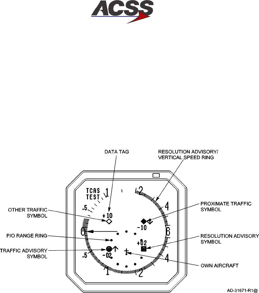
SYSTEM DESCRIPTION AND INSTALLATION MANUAL
TCAS 3000 Traffic Alert and Collision Avoidance System
34−43−23
Use or disclosure of information on this page is subject to the restrictions in the proprietary notice of this document.
Page 1−59/(1−60 blank)
15 Dec 2005
(2) TCAS Mode Activation
Prior to takeoff, activate TCAS as follows:
•Set TCAS/XPDR mode selector to TA/RA
•Set TA/DSPLY to AUTO
•Set ALT/RPTG to 1 or 2.
(3) TCAS Mode Deactivation
After clearing the runway following landing, set the TCAS/XPDR mode selector to
STBY to disable Mode S communication.
Figure 1−18. TCAS ll Display Test Pattern

SYSTEM DESCRIPTION AND INSTALLATION MANUAL
TCAS 3000 Traffic Alert and Collision Avoidance System
34−43−23
Use or disclosure of information on this page is subject to the restrictions in the proprietary notice of this document.
Page 2−1
15 Dec 2005
MECHANICAL INSTALLATION
1. General
This section contains information on how and where to mount each component of the TCAS
3000 system. For new installations, plan installation in two stages. First, determine location
of the LRUs in the aircraft. Next, determine the length of RF and electrical interconnections
for selected locations.
NOTE:The TCAS 3000 LRU, ACSS Part No. 9003000−10XXX can functionally replace a
TCAS 2000 LRU, Part No. 4066010−904, −905, or −907, in existing installations.
Certification approval must be obtained.
TCAS 2000 LRUs, Part No. 4066010−904, −905, −907, −910, or 7517900−10XXX
may replace the TCAS 3000 if properly demonstrated and certified.
2. Equipment and Materials
For new TCAS 3000 installations, refer to Table 1−1 for RCZ−852 Transponder Installation Kit
information and Table 1−2 for mounting tray information. For all other components, refer to
the applicable Outline and Installation drawing in this section for mounting information. The
Outline and Installation drawings show connector and connector contact pin/socket part
number information, where applicable.
3. Mechanical Installation Design
NOTE:To assure proper grounding of the TCAS 3000 system, the aircraft surface to which
all mountings or units are attached must be clean bare metal. Mount to the airframe
with a resistance of 5 milliohms or less.
A. TCAS 3000 Computer Unit Provisions
Mechanical installation data for the TCAS 3000 Computer Unit (6−MCU) is shown in
Figure 2−1. Data for the TCAS 3000 Computer Unit (4−MCU) is shown in Figure 2−2.
The computer unit can be mounted in any convenient location in the aircraft; however, it
must be located so as to maintain an antenna coaxial cable insertion loss of 2.5 ± 0.5 dB
in accordance with DO−185. This is approximately within 50 feet of the antenna unless
low loss coaxial cable is used. Top and bottom coaxial delay timing differences can be
compensated for by use of the antenna delay program pins.
The TCAS Computer Unit, Part No. 9003000−10XXX, is mounted in an ARINC 600
6−MCU mounting tray. The computer unit requires external cooling air in accordance with
ARINC 600 or ARINC 404 to maintain the highest possible Mean Time Between Failures
(MTBF). In those installations where this is not available, a mounting tray with an integral
fan is required.
The TCAS Computer Unit, Part No. 9003000−55XXX or 65XXX, is mounted in an ARINC
600 4−MCU mounting tray. This unit contains an internal temperature controlled fan, so it
does not require any external cooling.

SYSTEM DESCRIPTION AND INSTALLATION MANUAL
TCAS 3000 Traffic Alert and Collision Avoidance System
34−43−23
Use or disclosure of information on this page is subject to the restrictions in the proprietary notice of this document.
Page 2−2
15 Dec 2005
B. Antenna Provisions
The TCAS top directional antenna should, ideally, be the most forward antenna on the top
of the aircraft and should be located as close to the longitudinal centerline as possible.
See Figure 2−4. A 5−degree tilt angle is allowed laterally, with 2−degree positive and
5−degree negative tilt angles allowed longitudinally. See Figure 2−5.
If a bottom directional antenna is used, it should also be the most forward antenna on the
fuselage bottom. Tilt angle allowances are the same as on the top antenna. A bottom
omnidirectional antenna need not be the most forward antenna, but it should be
separated by at least 20−inches from any other L−band antenna.
Since the bottom antenna may be either a directional (standard) or an omnidirectional
(optional) antenna, dual notation is shown in the wiring diagram. Only one coax cable is
needed for an omnidirectional antenna installation.
(1) Directional Antenna Installation
The top directional antenna mounting and installation data is given in Figure 2−6.
Figure 2−6 contains the maximum radius dimensions for the various curved antenna
base part number units, the number of aircraft mounting holes and the length of the
connector extension for the various part number units. The antenna must be
electrically bonded (less than 5.0 milliohms bonding resistance) to the airframe to
provide a good ground contact for lightning protection.
The directional antenna must be separated by a least 30−inches from any other
L−band antenna, and 60−inches is preferred. If a bottom directional antenna is used,
it should be the most forward antenna on the fuselage bottom with tilt angle
allowances the same as for a top mounted antenna.
An O−ring (included with the directional antenna) is required to be installed between
the directional antenna and the aircraft fuselage. The Navy Aeronautical Standard
part number for the O−ring is NAS 1611−240. The ACSS part number for the O−ring
is 4000171−240.
NOTE: For directional antennas, ACSS Part No. 7514060−90X, the customer must
provide an adapter plate for mounting to the aircraft. The antenna base
plate, to which the adapter must mate, is detailed in Figure 2−7. Directional
antennas, ACSS Part No. 7514081−9XX, come with a preinstalled adapter
plate.
(2) Omnidirectional Antenna Installation
The bottom omnidirectional antenna is a standard ATC type antenna. It should be
qualified to TSO C119a and be dc grounded per MIL−A−90941, B−5087B. All
L−band antennas must be separated by at least 20−inches. Only one coax cable is
required for installation.
The omnidirectional antenna is not supplied by ACSS. To install, follow the
manufacturer’s installation instructions.

SYSTEM DESCRIPTION AND INSTALLATION MANUAL
TCAS 3000 Traffic Alert and Collision Avoidance System
34−43−23
Use or disclosure of information on this page is subject to the restrictions in the proprietary notice of this document.
Page 2−3
15 Dec 2005
C. Control Panel Provisions
Mechanical installation data for the ACSS ATC/TCAS Control Panels is shown in
Figure 2−8 and Figure 2−9. The control panel is supplied in either a dual Mode S/TCAS
configuration shown in Figure 2−8, or an ATCRBS−Mode S/TCAS configuration shown in
Figure 2−9.
Mechanical installation data a typical Gables GXXXX Series ATC/TCAS control panel is
shown in Figure 2−10.
It should be noted that various other types of controllers (Radio Management Units or
EFIS Display Controllers) can be used to control the TCAS display. If a controller other
than a ACSS ATC/TCAS control panel is used, refer to that particular unit’s manual for
installation data.
D. VSI/TRA Provisions
Mechanical installation data for the ACSS VSI/TRA display is shown in Figure 2−11. The
VSI/TRA is usually used as a direct replacement for the existing 3−ATI form VSI indicator
currently mounted in the cockpit. Replacement of the installation clamp may be
necessary if the previous clamp is less than 2−inches deep. Some older aircraft clamps
do not provide sufficient mechanical support.
If a ACSS VSI/TRA is used as the TCAS display source, and an Air Data Computer is not
available to provide vertical speed signals to the display, the installation must include a
ACSS PTM to supply air data signals to the VSI/TRA. These signals are derived from a
static pneumatic input.
E. Pressure Transducer Module (PTM) Provisions
Mechanical installation data for the PTM is shown in Figure 2−12. The PTM is configured
to be mounted on a mounting bracket designed for use in a restricted access area or on a
mounting plate for mounting in an ARINC 408A 3ATI round instrument panel space.
The PTM is conduction, radiation, and natural convection cooled. It does not require any
external cooling as long as it is installed in a pressurized area where the ambient
temperature is within the established temperature range of the device.

SYSTEM DESCRIPTION AND INSTALLATION MANUAL
TCAS 3000 Traffic Alert and Collision Avoidance System
34−43−23
Use or disclosure of information on this page is subject to the restrictions in the proprietary notice of this document.
Page 2−4
15 Dec 2005
F. Transponder Provisions
This paragraph contains the mechanical installation data for the ACSS Mode S Data Link
Transponder, Part No. 7517800−XXYYY and ACSS Diversity Mode S Transponder, Part
No. 7510700−850/−951. It also contains provisions for installing the ATC transponder
antennas.
(1) Mode S Data Link Transponder Provisions
Mechanical installation data for the ACSS Mode S Data Link Transponder, Part No.
7517800−XXYYY is shown in Figure 2−13. The transponder can be mounted in any
convenient location in the aircraft; however, it should be mounted within 30 feet of the
antennas unless low loss coaxial cable is used to maintain a worst case loss of 3dB
per ARINC 718−A. Top and bottom antenna coaxial run length differences can be
compensated for by use of the antenna delay program pins on the transponder. The
unit can utilize external cooling air in accordance with ARINC 600 or ARINC 404 or
operate in convection−cooled environments. The transponder is mounted in an
ARINC 600 4−MCU tray assembly.
(2) Diversity Mode S Transponder Provisions
Mechanical installation data for the ACSS RCZ−852 Diversity Mode S Transponder,
Part No. 7510700−850/−951 is shown in Figure 2−14. The transponder can be
mounted in any convenient location in the aircraft that allows the unit to be upright
during normal flight. The exact location should allow the cabling between the unit,
control panel, and antennas to be as short as possible. The location of the mounting
tray (part of installation kit, Part No. 7510707−968) should allow adequate space for
installation of the transponder, provide reasonable accessibility for servicing, and
allow space on top, sides, and rear of unit for adequate ventilation. The location
must also provide a solid mechanical mount to prevent vibration amplification. The
mounting tray should be electrically bonded to the aircraft frame by a low resistance
path of less than 2.5 milliohms.
(3) ATC Transponder Antenna Provisions
When installing transponder antennas, a TSO’d antenna should be selected. The
antenna must be vertically polarized and operate in the frequency range of 960 to
1220 MHz. Antenna impedance must be 50 ohms. Voltage standing wave ratio
(VSWR) shall not exceed 1.5:1. Selection of a grounded or lightning protected type
antenna is required to pass the transponder bite continuity detection circuitry, if
enabled.
In dual transponder antenna installations it is important to provide adequate isolation
from each other to prevent receiver front−end damage. A 20−inch minimum
separation of Mode S antennas from other L−Band antennas, including TCAS
antennas, must be maintained. The maximum cable length for RG−214/U is 30 feet
(9.144 meters). Allow adequate cable length so bends in cable have a minimum
3−inch (76 mm) radius. Selection of coax cable assemblies with moisture barrier
protection is highly recommended to minimize the effects of humidity and corrosion.

SYSTEM DESCRIPTION AND INSTALLATION MANUAL
TCAS 3000 Traffic Alert and Collision Avoidance System
34−43−23
Use or disclosure of information on this page is subject to the restrictions in the proprietary notice of this document.
Page 2−5
15 Dec 2005
When you install ATC antennas, the mounting area must provide a solid mechanical
base for the antenna as well as clearance for the connector. A doubler plate is
usually required when the antenna is mounted on an unsupported large fuselage
area. Never weaken aircraft structure for the sake of a good location. Refer to the
aircraft manufacturer’s specifications; reinforcements for antennas are often built into
the aircraft structure.
Doubler plates or shims, if used, must be metallic and shaped to interface the
antenna base with the contour of the aircraft fuselage. ATC antennas are not
supplied by ACSS. All antenna installations should be in accordance with
manufacturer installation instructions.
A weather sealant should be applied around the periphery of the antenna base to
prevent seepage of water and condensation and preclude corrosion. If a sealant or
aerodynamic smoother is used, it should be applied after the antenna has been
bolted down.

SYSTEM DESCRIPTION AND INSTALLATION MANUAL
TCAS 3000 Traffic Alert and Collision Avoidance System
34−43−23
Use or disclosure of information on this page is subject to the restrictions in the proprietary notice of this document.
Page 2−6
15 Dec 2005
Blank Page
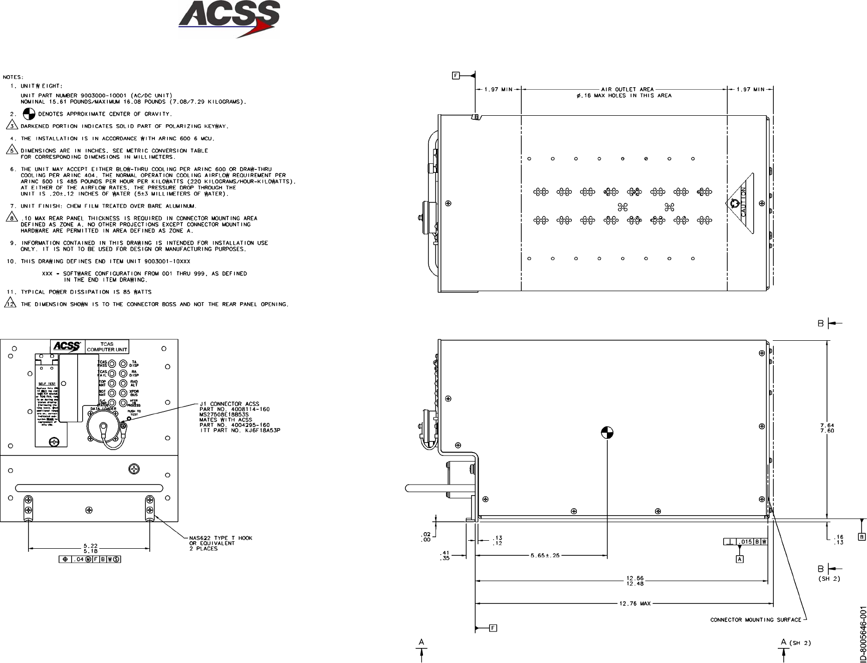
SYSTEM DESCRIPTION AND INSTALLATION MANUAL
TCAS 3000 Traffic Alert and Collision Avoidance System
34−43−23
Use or disclosure of information on this page is subject to the restrictions in the proprietary notice of this document.
Page 2−7/(2−8 blank)
15 Dec 2005
Figure 2−1 (Sheet 1). TCAS 3000 Computer Unit Outline and Installation Drawing
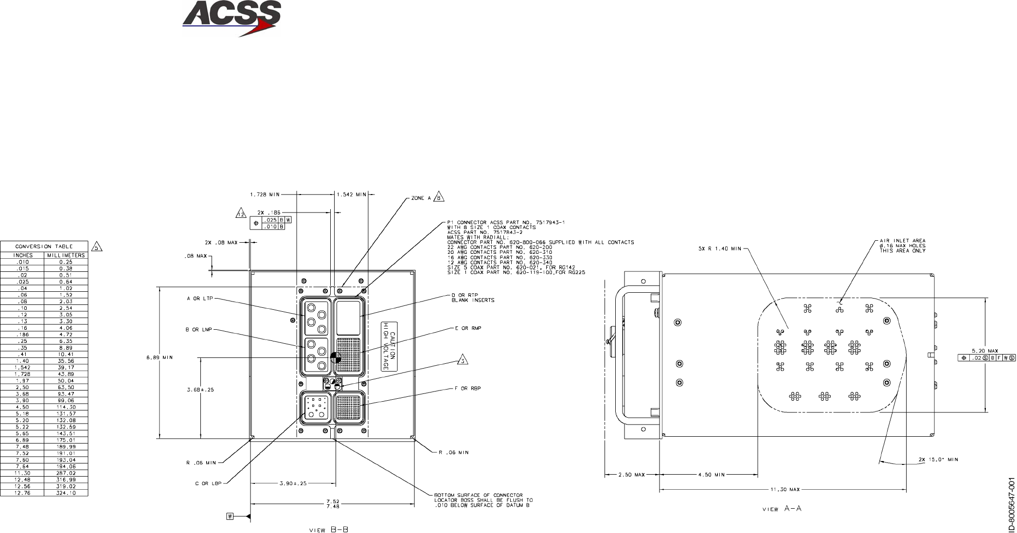
SYSTEM DESCRIPTION AND INSTALLATION MANUAL
TCAS 3000 Traffic Alert and Collision Avoidance System
34−43−23
Use or disclosure of information on this page is subject to the restrictions in the proprietary notice of this document.
Page 2−9/(2−10 blank)
15 Dec 2005
Figure 2−1 (Sheet 2). TCAS 3000 Computer Unit Outline and Installation Drawing
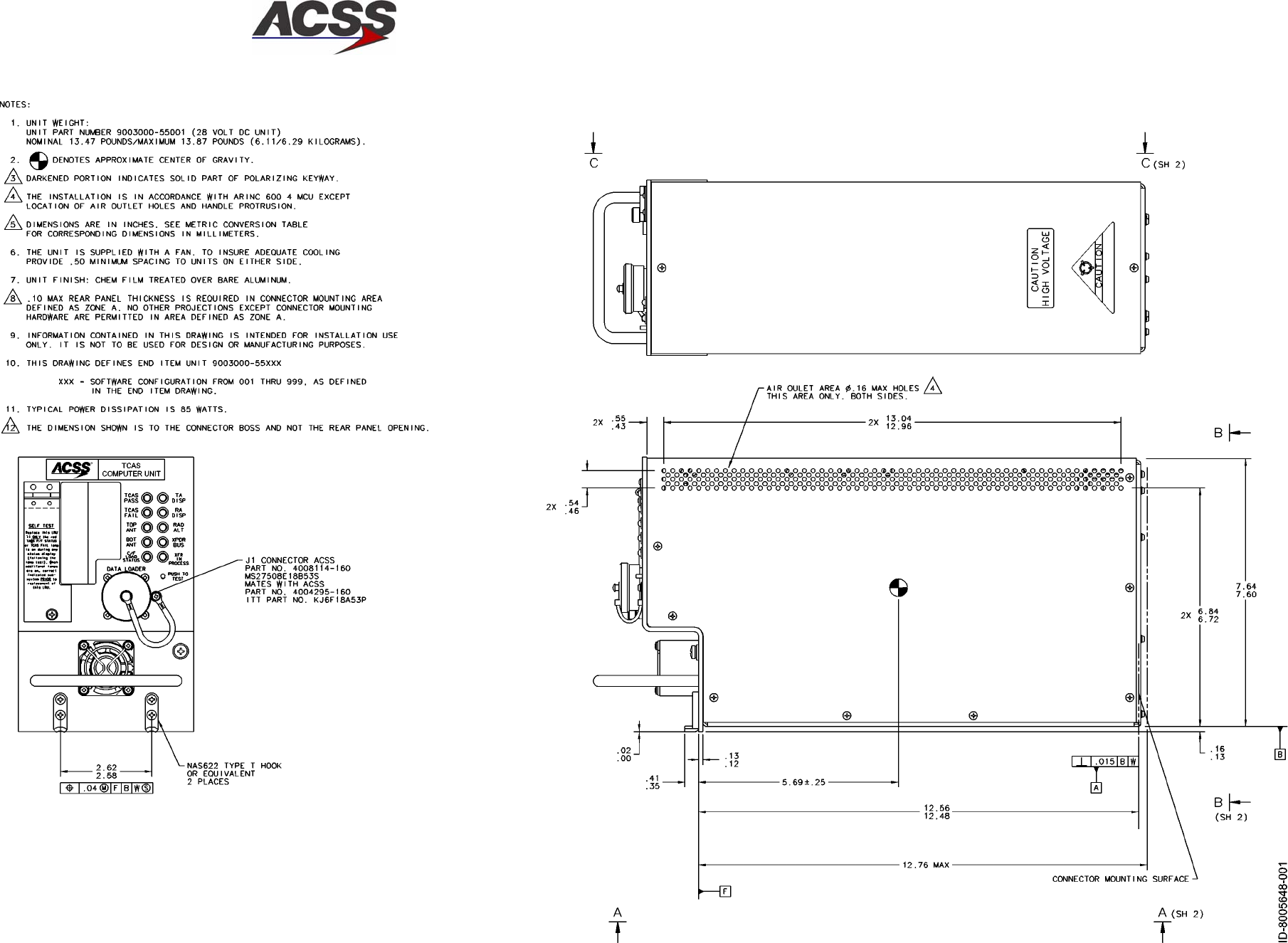
SYSTEM DESCRIPTION AND INSTALLATION MANUAL
TCAS 3000 Traffic Alert and Collision Avoidance System
34−43−23
Use or disclosure of information on this page is subject to the restrictions in the proprietary notice of this document.
Page 2−11/(2−12 blank)
15 Dec 2005
Figure 2−2 (Sheet 1). TCAS 3000 Computer Unit Outline and Installation Diagram
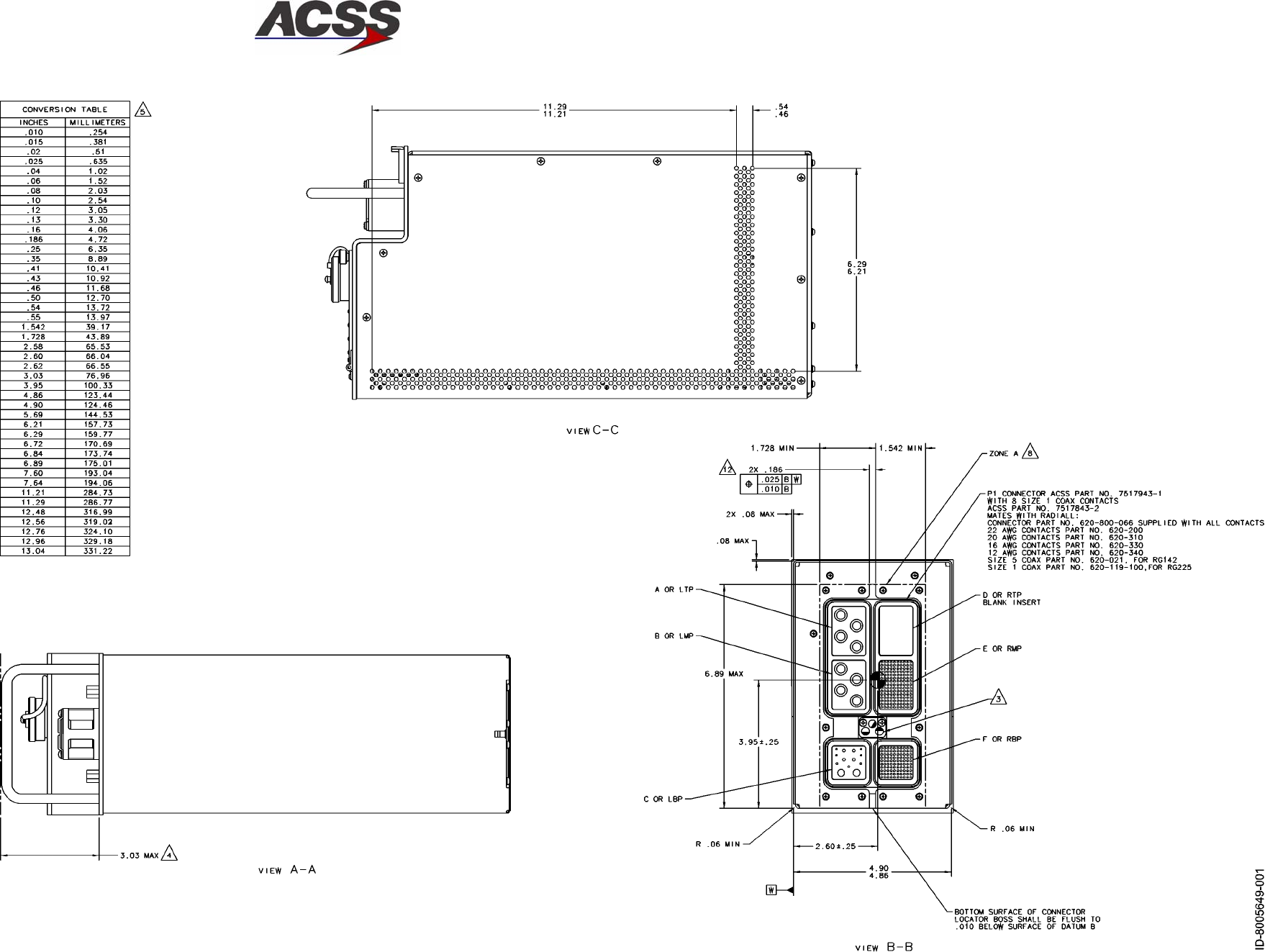
SYSTEM DESCRIPTION AND INSTALLATION MANUAL
TCAS 3000 Traffic Alert and Collision Avoidance System
34−43−23
Use or disclosure of information on this page is subject to the restrictions in the proprietary notice of this document.
Page 2−13/(2−14 blank)
15 Dec 2005
Figure 2−2 (Sheet 2). TCAS 3000 Computer Unit Outline and Installation Diagram
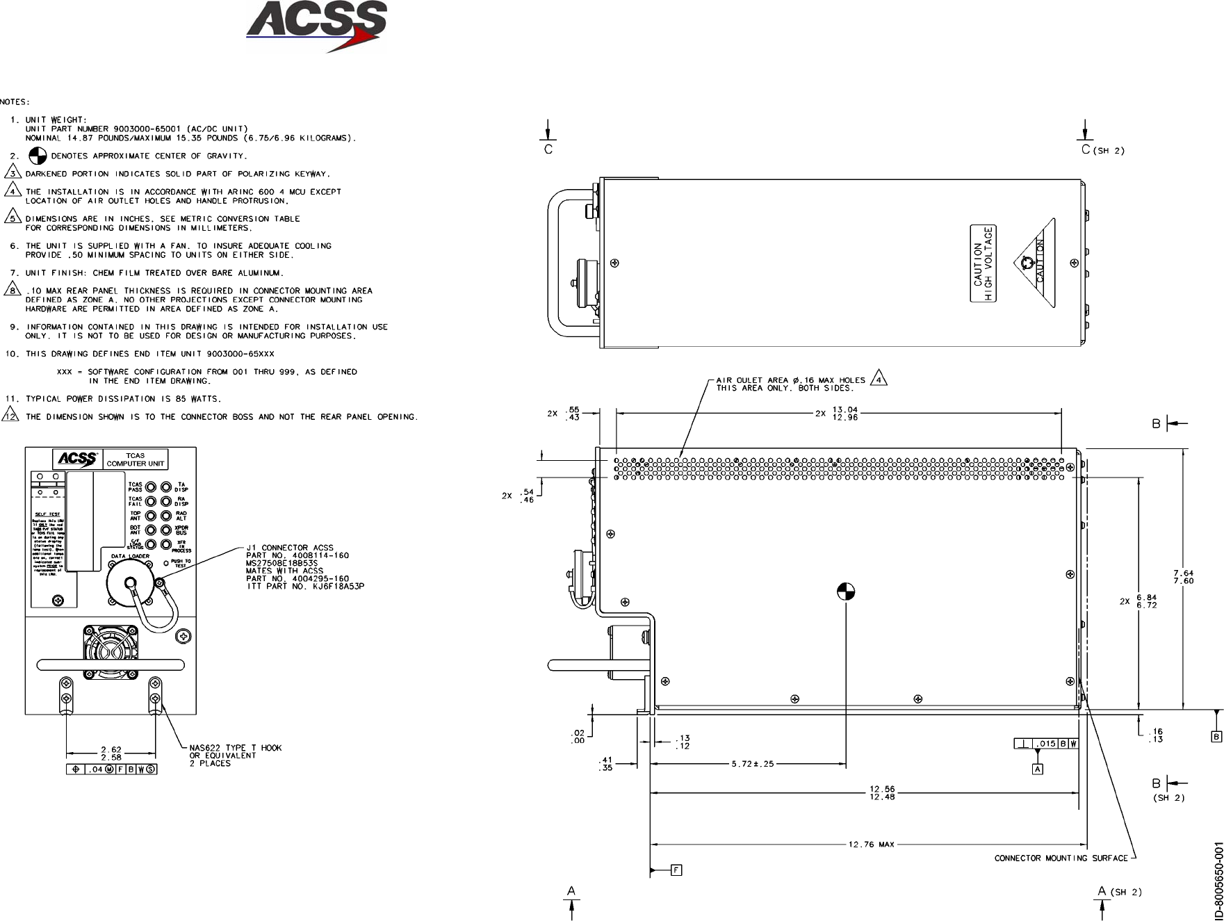
SYSTEM DESCRIPTION AND INSTALLATION MANUAL
TCAS 3000 Traffic Alert and Collision Avoidance System
34−43−23
Use or disclosure of information on this page is subject to the restrictions in the proprietary notice of this document.
Page 2−15/(2−16 blank)
15 Dec 2005
Figure 2−3 (Sheet 1). TCAS 3000 Computer Unit Outline and Installation Diagram
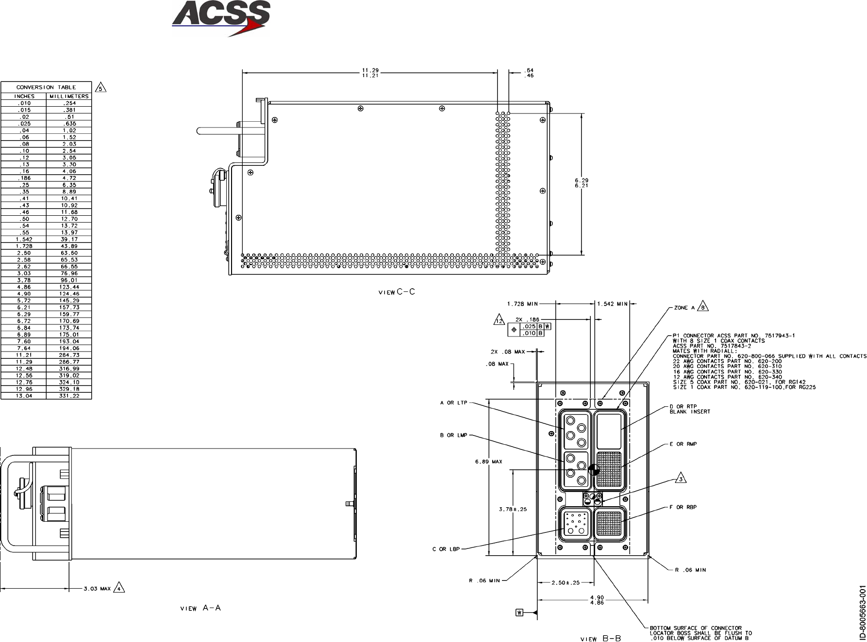
SYSTEM DESCRIPTION AND INSTALLATION MANUAL
TCAS 3000 Traffic Alert and Collision Avoidance System
34−43−23
Use or disclosure of information on this page is subject to the restrictions in the proprietary notice of this document.
Page 2−17/(2−18 blank)
15 Dec 2005
Figure 2−3 (Sheet 2). TCAS 3000 Computer Unit Outline and Installation Diagram
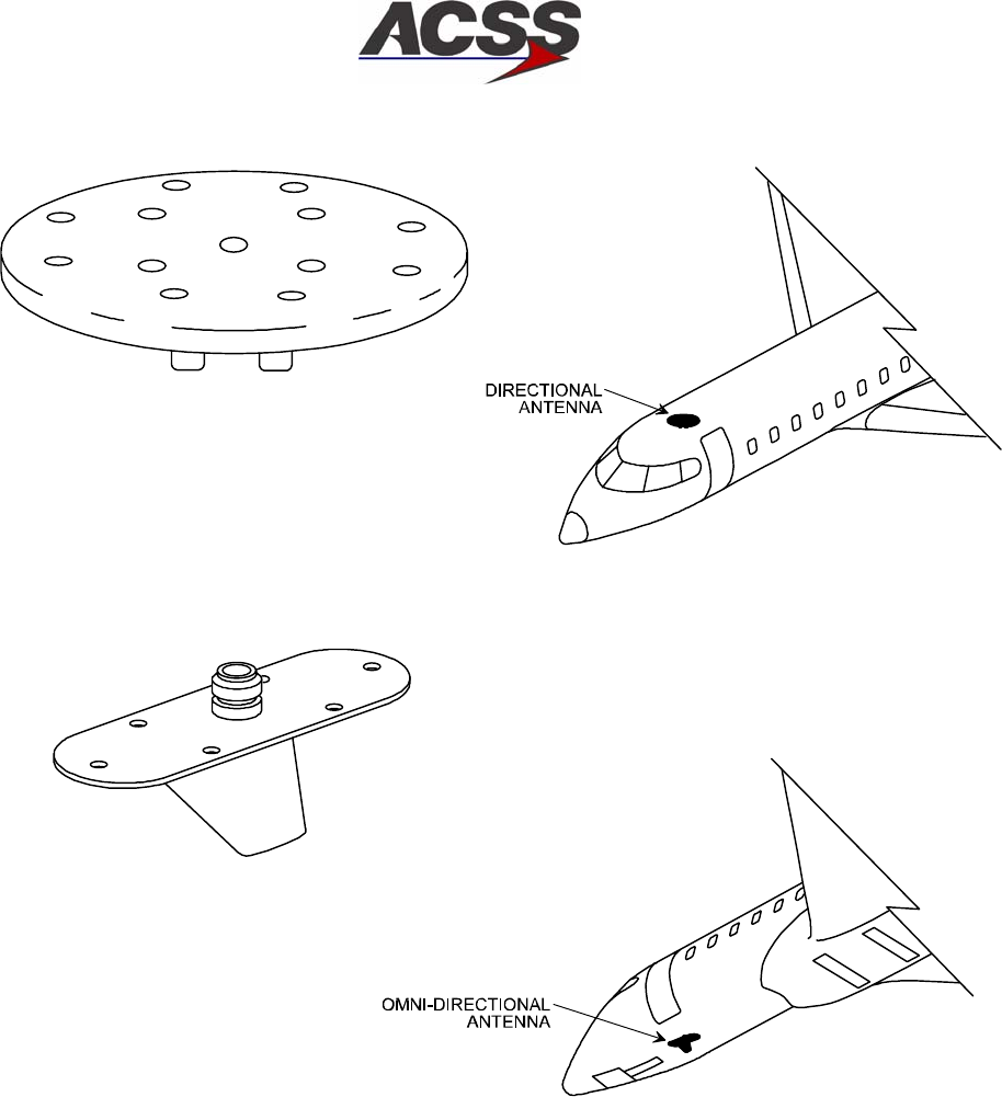
SYSTEM DESCRIPTION AND INSTALLATION MANUAL
TCAS 3000 Traffic Alert and Collision Avoidance System
34−43−23
Use or disclosure of information on this page is subject to the restrictions in the proprietary notice of this document.
Page 2−19
15 Dec 2005
AD−53006@
Figure 2−4. TCAS Directional and Omnidirectional Antenna Locations
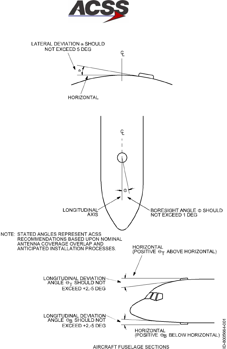
SYSTEM DESCRIPTION AND INSTALLATION MANUAL
TCAS 3000 Traffic Alert and Collision Avoidance System
34−43−23
Use or disclosure of information on this page is subject to the restrictions in the proprietary notice of this document.
Page 2−20
15 Dec 2005
Figure 2−5. Directional Antenna Angular Orientation
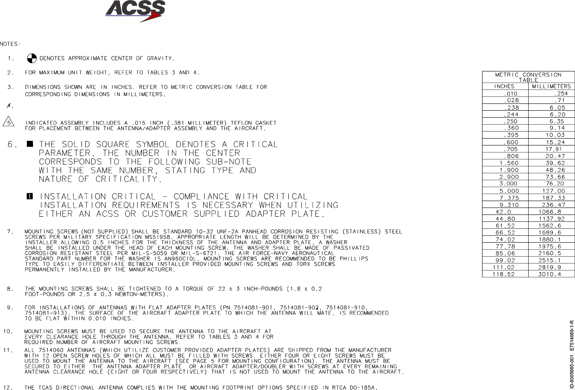
SYSTEM DESCRIPTION AND INSTALLATION MANUAL
TCAS 3000 Traffic Alert and Collision Avoidance System
34−43−23
Use or disclosure of information on this page is subject to the restrictions in the proprietary notice of this document.
Page 2−21/(2−22 blank)
15 Dec 2005
Figure 2−6 (Sheet 1). Directional Antenna Outline and Installation Diagram
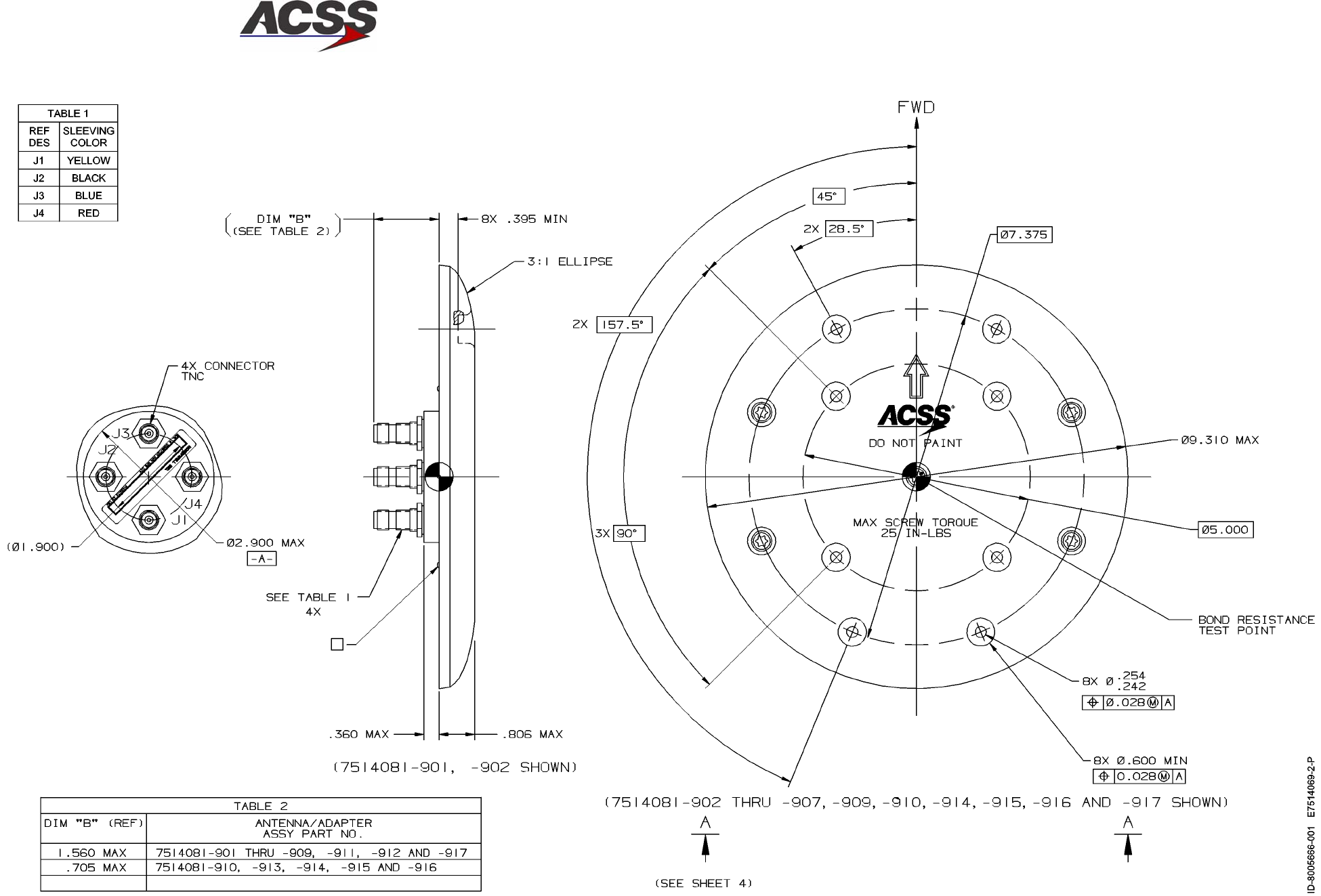
SYSTEM DESCRIPTION AND INSTALLATION MANUAL
TCAS 3000 Traffic Alert and Collision Avoidance System
34−43−23
Use or disclosure of information on this page is subject to the restrictions in the proprietary notice of this document.
Page 2−23/(2−24 blank)
15 Dec 2005
Figure 2−6 (Sheet 2). Directional Antenna Outline and Installation Diagram
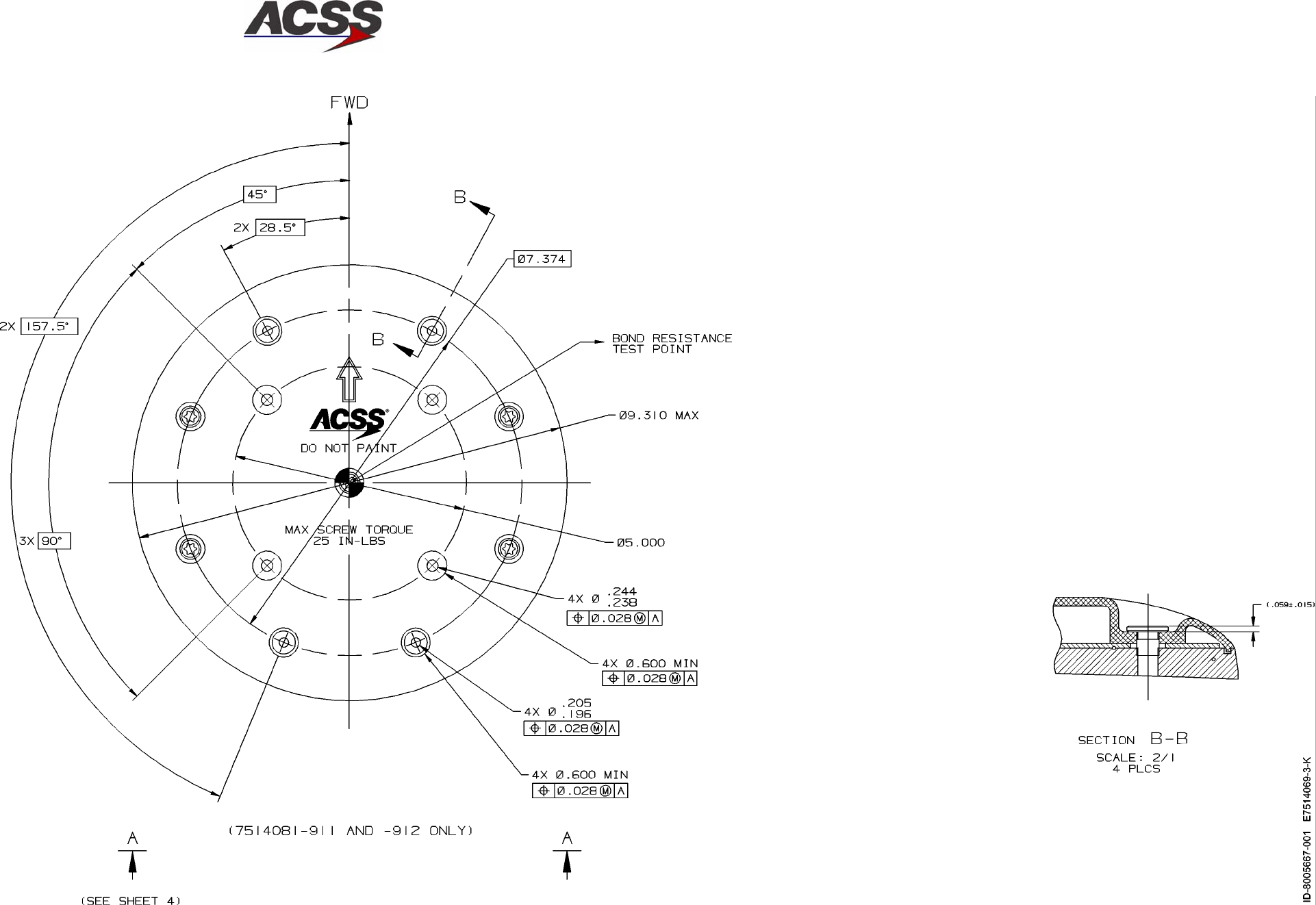
SYSTEM DESCRIPTION AND INSTALLATION MANUAL
TCAS 3000 Traffic Alert and Collision Avoidance System
34−43−23
Use or disclosure of information on this page is subject to the restrictions in the proprietary notice of this document.
Page 2−25/(2−26 blank)
15 Dec 2005
Figure 2−6 (Sheet 3). Directional Antenna Outline and Installation Diagram
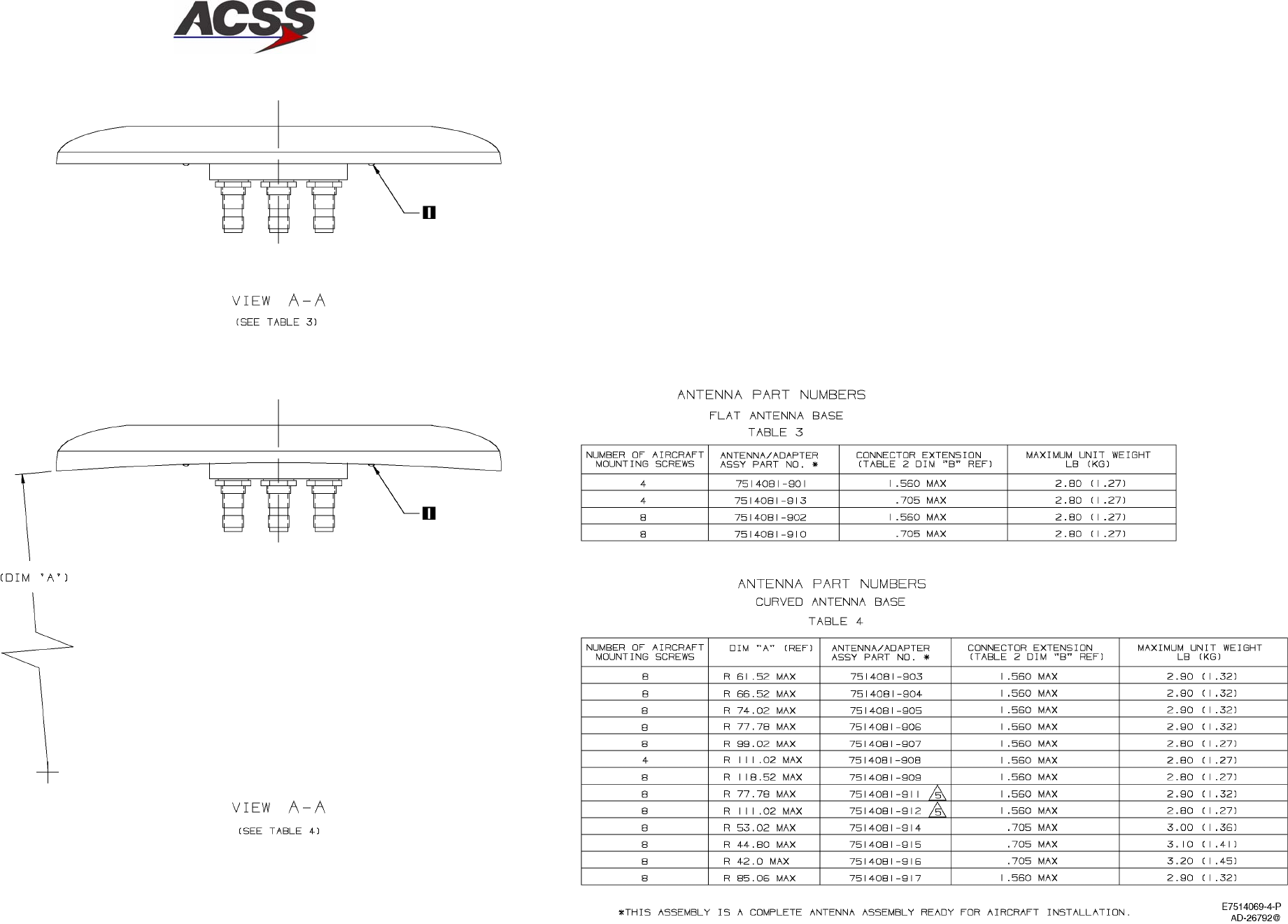
SYSTEM DESCRIPTION AND INSTALLATION MANUAL
TCAS 3000 Traffic Alert and Collision Avoidance System
34−43−23
Use or disclosure of information on this page is subject to the restrictions in the proprietary notice of this document.
Page 2−27/(2−28 blank)
15 Dec 2005
Figure 2−6 (Sheet 4). Directional Antenna Outline and Installation Diagram
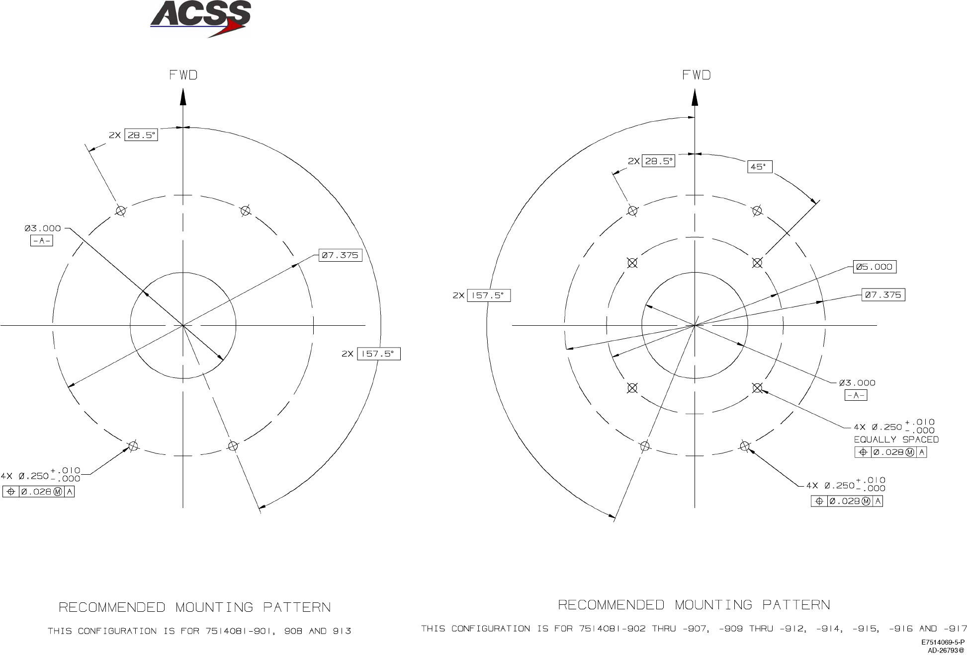
SYSTEM DESCRIPTION AND INSTALLATION MANUAL
TCAS 3000 Traffic Alert and Collision Avoidance System
34−43−23
Use or disclosure of information on this page is subject to the restrictions in the proprietary notice of this document.
Page 2−29/(2−30 blank)
15 Dec 2005
Figure 2−6 (Sheet 5). Directional Antenna Outline and Installation Diagram
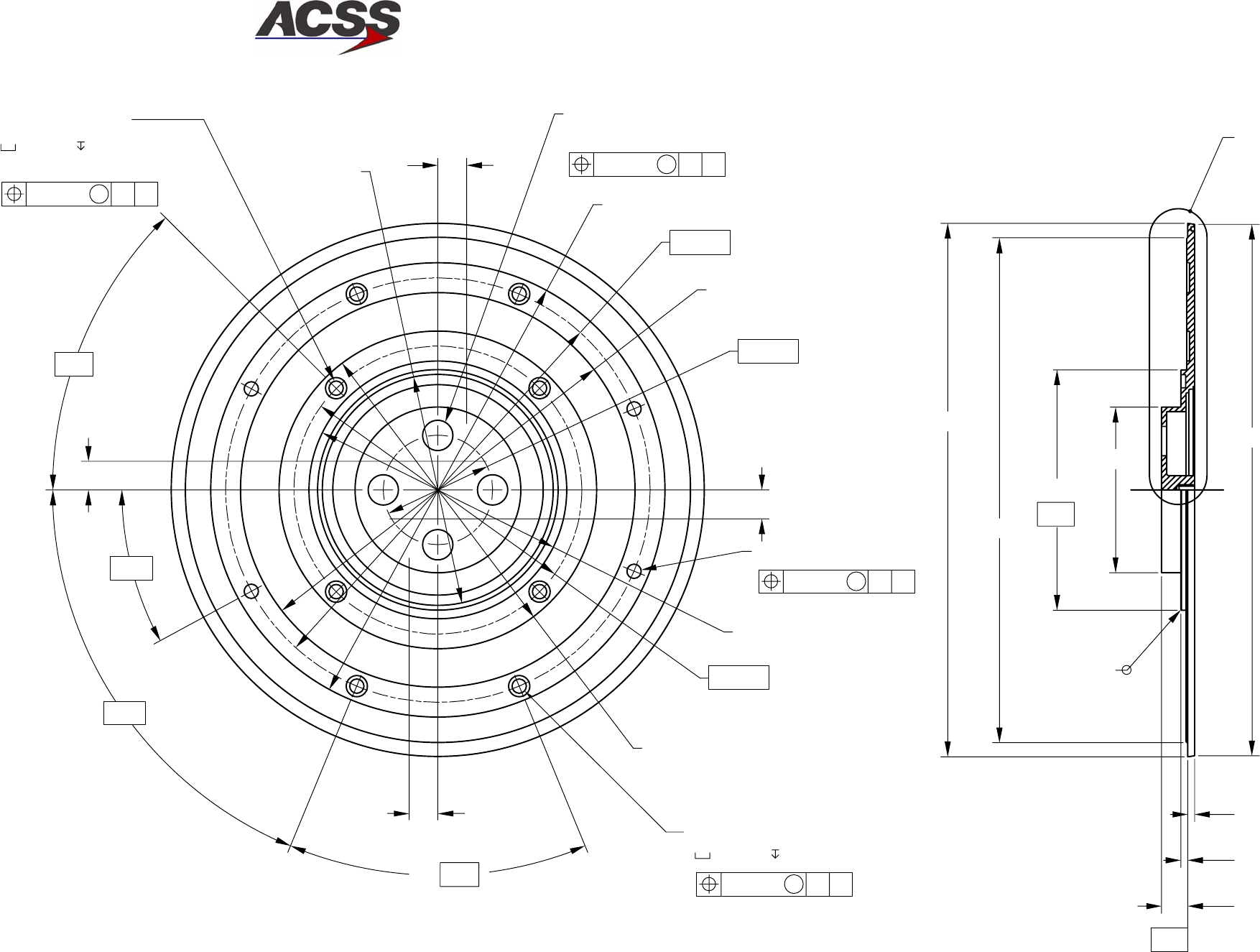
SYSTEM DESCRIPTION AND INSTALLATION MANUAL
TCAS 3000 Traffic Alert and Collision Avoidance System
34−43−23
Use or disclosure of information on this page is subject to the restrictions in the proprietary notice of this document.
Page 2−31/(2−32 blank)
15 Dec 2005
−0.005
+0.000
ADETAIL
Ø 4.180 ? 0.002
Ø 9.266
45º
0.455
Ø 8.760
0.120
0.120
Ø 2.880
Ø 9.232
0.010 x 45º
0.50
0.50
0.50
4X Ø 0.250 +0.004
−0.001
Ø 0.370 0.050
ID−39469 E7514061, SH2
5X
0.50
J3
J1
J2
J4
67.5º
45º
28.5º2X
Ø 5.520
Ø 5.000
4.480
Ø 0.028 M A B
4X Ø 0.250 +0.004
−0.001
Ø 0.028 M A B
− B −
Ø 1.900
Ø 6.855
Ø 7.375
Ø 7.895
4X Ø 0.516 +0.006
−0.002
Ø 0.014 M A B
EQUALLY SPACED
Ø 4.012 +0.000
−0.010
−0.005
+0.000
4X Ø 0.250 +0.004
−0.001
Ø 0.370 0.050
Ø 0.028 M A B
EQUALLY SPACED
− A −
NOTE:
Customer supplied adapter plates must mate with this surface.
Figure 2−7 (Sheet 1). Directional Antenna Baseplate Outline and Installation Diagram
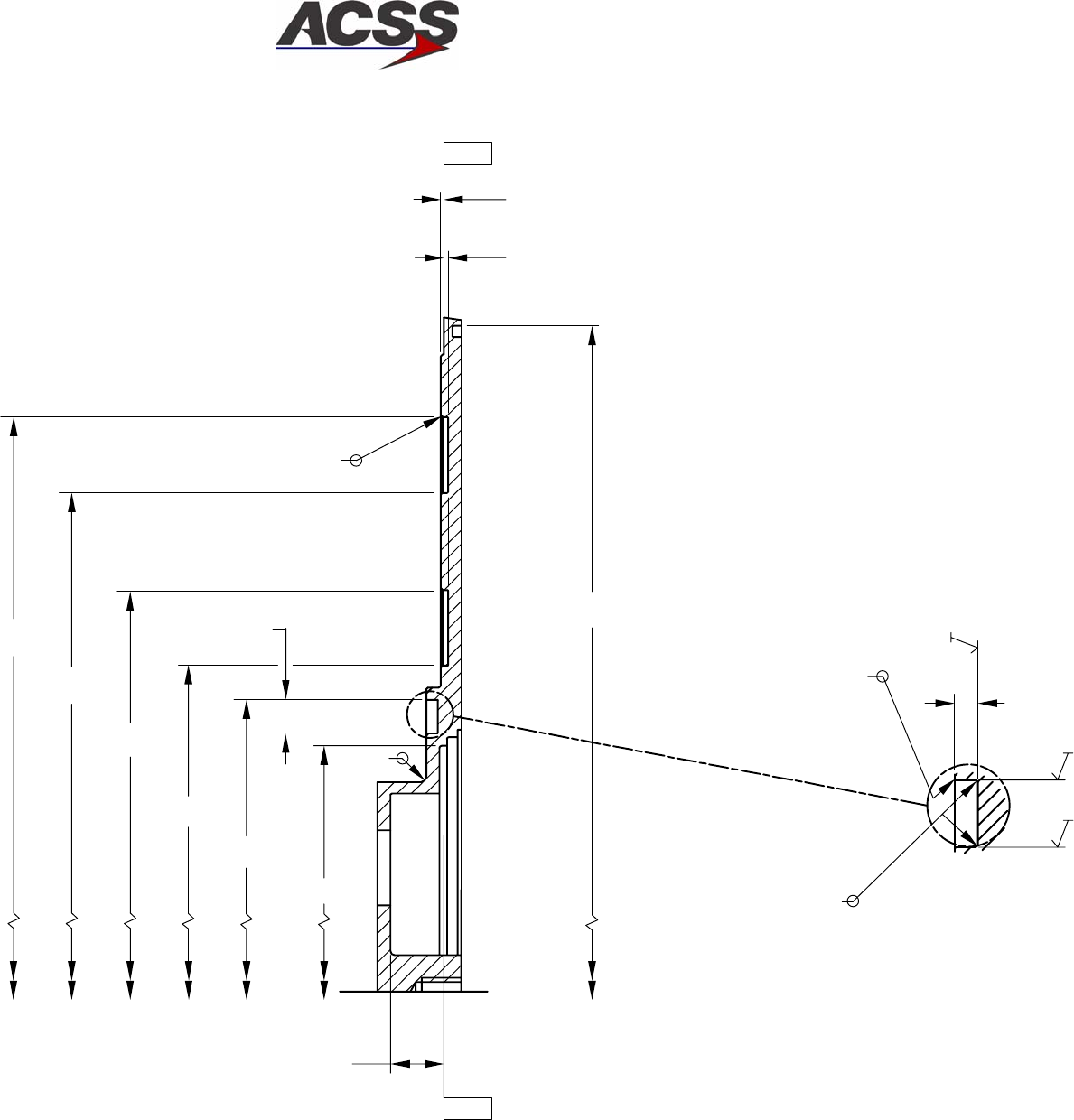
SYSTEM DESCRIPTION AND INSTALLATION MANUAL
TCAS 3000 Traffic Alert and Collision Avoidance System
34−43−23
Use or disclosure of information on this page is subject to the restrictions in the proprietary notice of this document.
Page 2−33/(2−34 blank)
15 Dec 2005
ID−39470 E514061, SH3
DETAIL A
0.080
(Ø 9.150)
0.020
0.030
(Ø 4.012)
(Ø 4.480)
(Ø 5.520)
0.232
(Ø 6.855)
(Ø 7.895)
5X 0.020 x 45º
+0.010
−0.000
R 0.010
2X 0.005 +0.005
−0.000
+0.015
−0.000
+0.006
−0.000
32
32
32
0.365 TO
DATUM A
(Ø 3.378)
R 0.06
− A −
− A −
45º
Figure 2−7 (Sheet 2). Directional Antenna Baseplate Outline and Installation Diagram
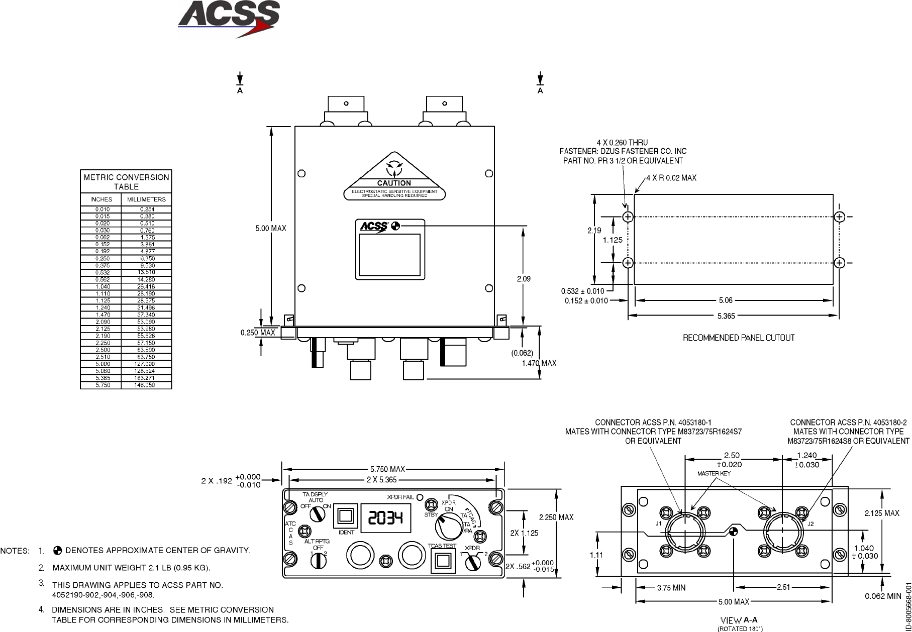
SYSTEM DESCRIPTION AND INSTALLATION MANUAL
TCAS 3000 Traffic Alert and Collision Avoidance System
34−43−23
Use or disclosure of information on this page is subject to the restrictions in the proprietary notice of this document.
Page 2−35/(2−36 blank)
15 Dec 2005
Figure 2−8. Control Panel (Dual Mode S) Outline and Installation Diagram
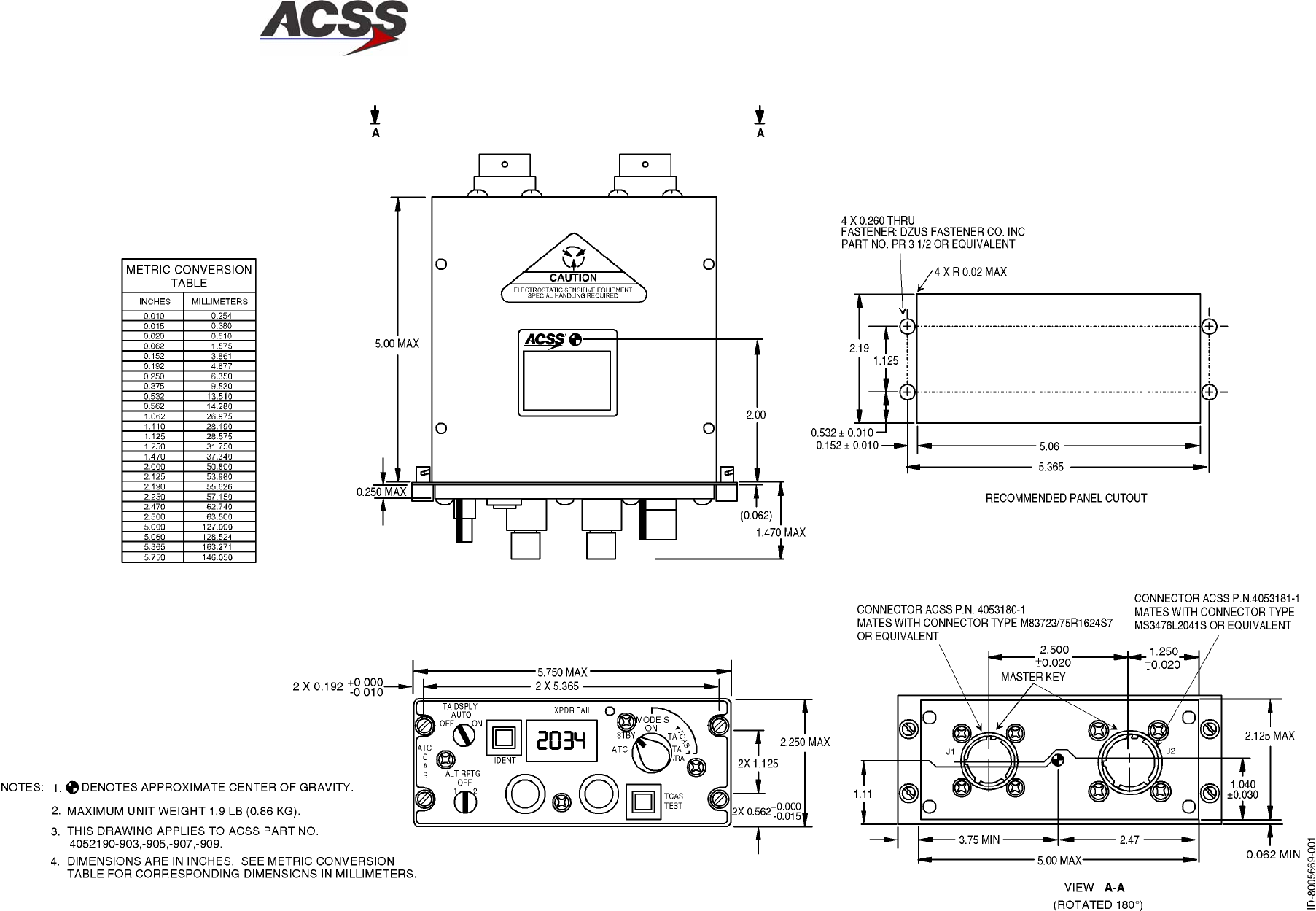
SYSTEM DESCRIPTION AND INSTALLATION MANUAL
TCAS 3000 Traffic Alert and Collision Avoidance System
34−43−23
Use or disclosure of information on this page is subject to the restrictions in the proprietary notice of this document.
Page 2−37/(2−38 blank)
15 Dec 2005
Figure 2−9. Control Panel (ATCRBS−Mode S) Outline and Installation Diagram
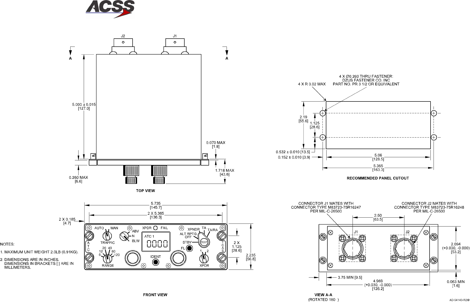
SYSTEM DESCRIPTION AND INSTALLATION MANUAL
TCAS 3000 Traffic Alert and Collision Avoidance System
34−43−23
Use or disclosure of information on this page is subject to the restrictions in the proprietary notice of this document.
Page 2−39/(2−40 blank)
15 Dec 2005
Figure 2−10.
Gables G7130−XX Control Panel Outline and Installation Diagram
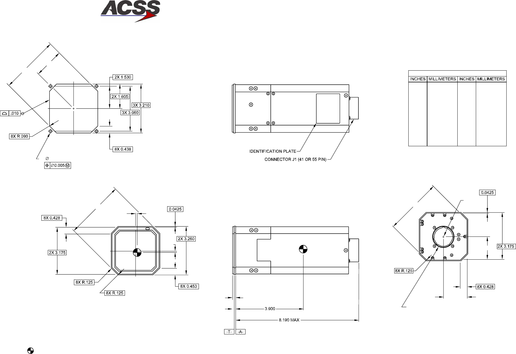
SYSTEM DESCRIPTION AND INSTALLATION MANUAL
TCAS 3000 Traffic Alert and Collision Avoidance System
34−43−23
Use or disclosure of information on this page is subject to the restrictions in the proprietary notice of this document.
Page 2−41/(2−42 blank)
15 Dec 2005
(2X 3.920)
(2X 1.960)
4X 0.177 THRU
RECOMMENDED
PANEL CUTOUT
0.10
0.10
(2X 3.970)
TOP VIEW
.225
.135
(PIN 1)
1.590
(2X 3.885)
1.590
CONNECTOR J1 (41 PIN) MATES WITH
M83723/75R2041N OR EQUIVALENT
41−PIN CONNECTOR BACKSHELL IS
M85049/52−1−20N OR EQUIVALENT
CONNECTOR J1 (55 PIN) MATES WITH
M83723/75R2255N OR EQUIVALENT
55−PIN CONNECTOR BACKSHELL IS
M85049/52−1−22N OR EQUIVALENT
AD−31673−R1@
CONVERSION TABLE
0.005 0.13 1.530
0.010 0.25 1.590
0.015 0.38 1.605
0.0425 1.08 1.960
0.090 2.29 3.060
0.100 2.54 3.175
0.125 3.18 3.210
0.135 3.43 3.260
0.177 4.50 3.885
0.225 5.72 3.900
0.428 10.87 3.920
0.438 11.13 3.970
0.453 11.51 8.190
38.86
40.39
40.77
49.78
77.72
80.65
81.53
82.80
98.68
99.06
99.57
100.84
208.03
NOTES: MAXIMUM WEIGHT 4.0 LBS (1.81 KG).
DIMENSIONS SHOWN ARE IN INCHES.
REFER TO METRIC CONVERSION TABLE FOR
CORRESPONDING DIMENSIONS IN MILLIMETERS.
DENOTES APPROXIMATE CENTER OF GRAVITY.
1.
2.
3.
Figure 2−11. VSI/TRA Outline and Installation Diagram
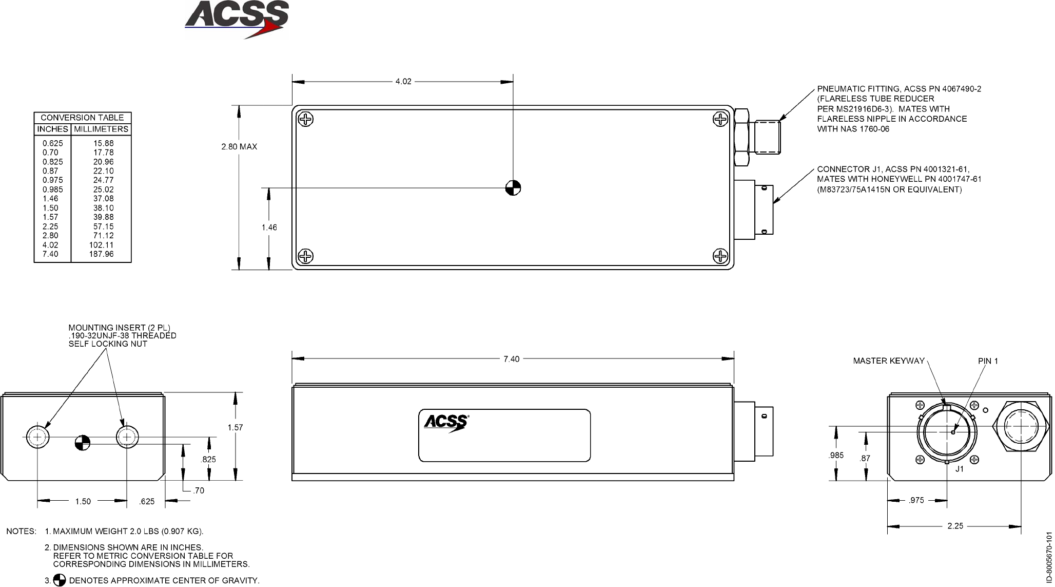
SYSTEM DESCRIPTION AND INSTALLATION MANUAL
TCAS 3000 Traffic Alert and Collision Avoidance System
34−43−23
Use or disclosure of information on this page is subject to the restrictions in the proprietary notice of this document.
Page 2−43/(2−44 blank)
15 Dec 2005
Figure 2−12 (Sheet 1). Pressure Transducer Module Outline and Installation Diagram
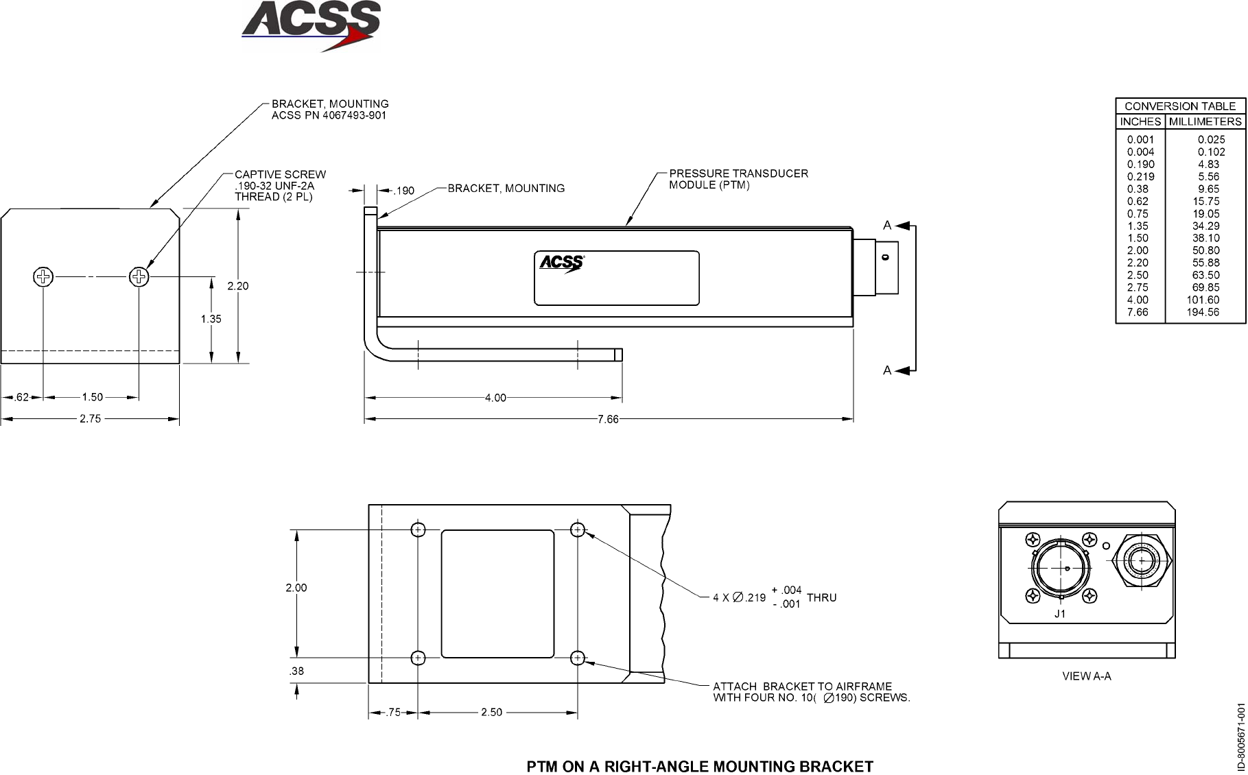
SYSTEM DESCRIPTION AND INSTALLATION MANUAL
TCAS 3000 Traffic Alert and Collision Avoidance System
34−43−23
Use or disclosure of information on this page is subject to the restrictions in the proprietary notice of this document.
Page 2−45/(2−46 blank)
15 Dec 2005
Figure 2−12 (Sheet 2). Pressure Transducer Module Outline and Installation Diagram
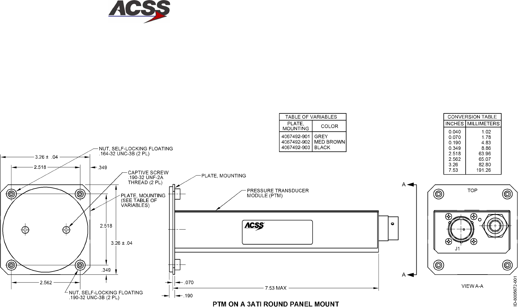
SYSTEM DESCRIPTION AND INSTALLATION MANUAL
TCAS 3000 Traffic Alert and Collision Avoidance System
34−43−23
Use or disclosure of information on this page is subject to the restrictions in the proprietary notice of this document.
Page 2−47/(2−48 blank)
15 Dec 2005
Figure 2−12 (Sheet 3). Pressure Transducer Module Outline and Installation Diagram
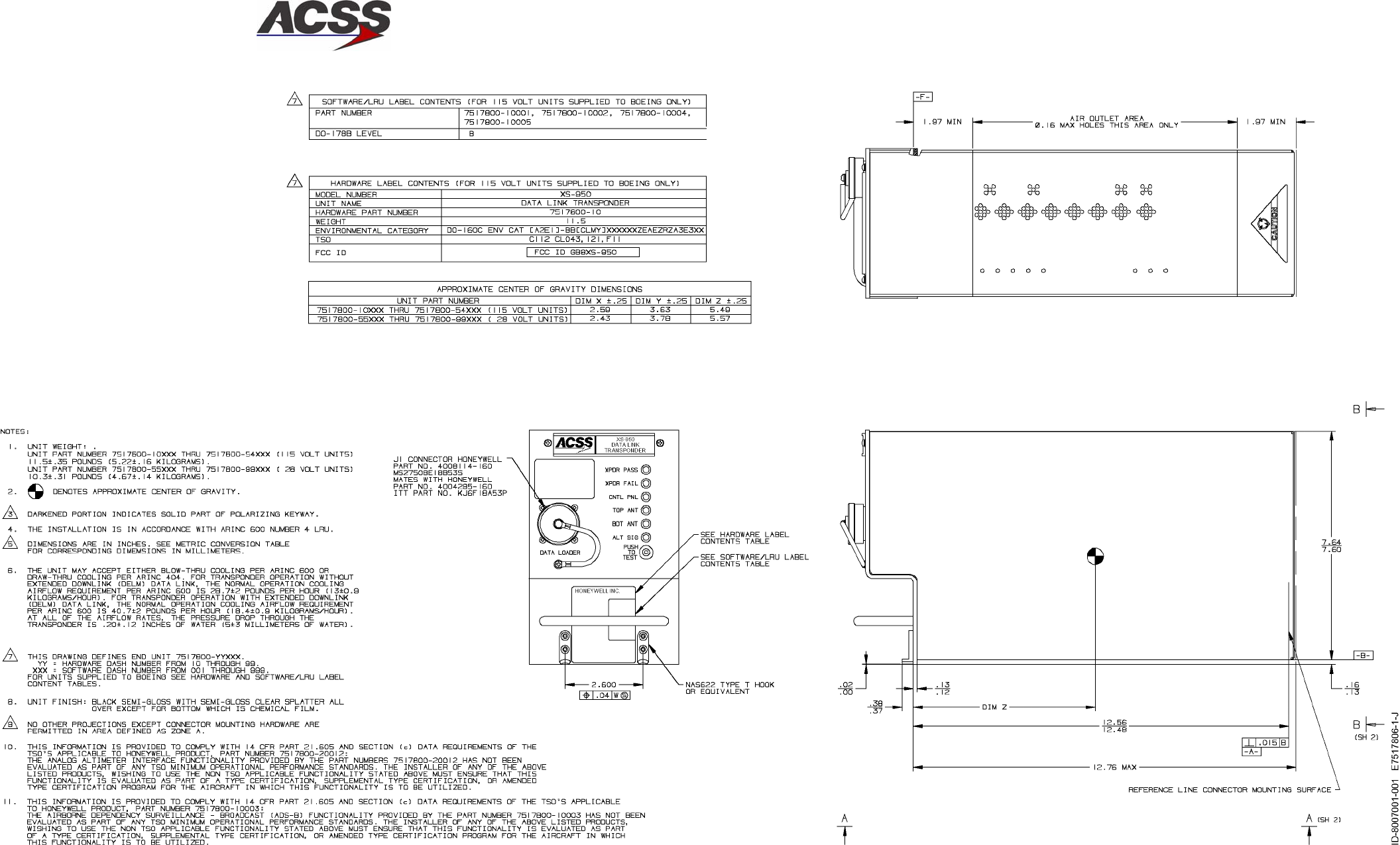
SYSTEM DESCRIPTION AND INSTALLATION MANUAL
TCAS 3000 Traffic Alert and Collision Avoidance System
34−43−23
Use or disclosure of information on this page is subject to the restrictions in the proprietary notice of this document.
Page 2−49/(2−50 blank)
15 Dec 2005
Figure 2−13 (Sheet 1). XS−950 Data Link Transponder Outline and Installation Diagram
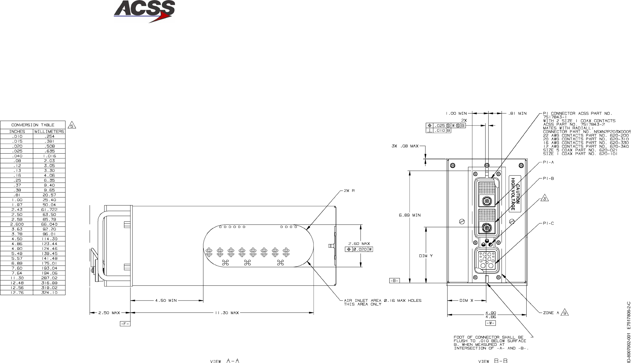
SYSTEM DESCRIPTION AND INSTALLATION MANUAL
TCAS 3000 Traffic Alert and Collision Avoidance System
34−43−23
Use or disclosure of information on this page is subject to the restrictions in the proprietary notice of this document.
Page 2−51/(2−52 blank)
15 Dec 2005
Figure 2−13 (Sheet 2). XS−950 Data Link Transponder Outline and Installation Diagram
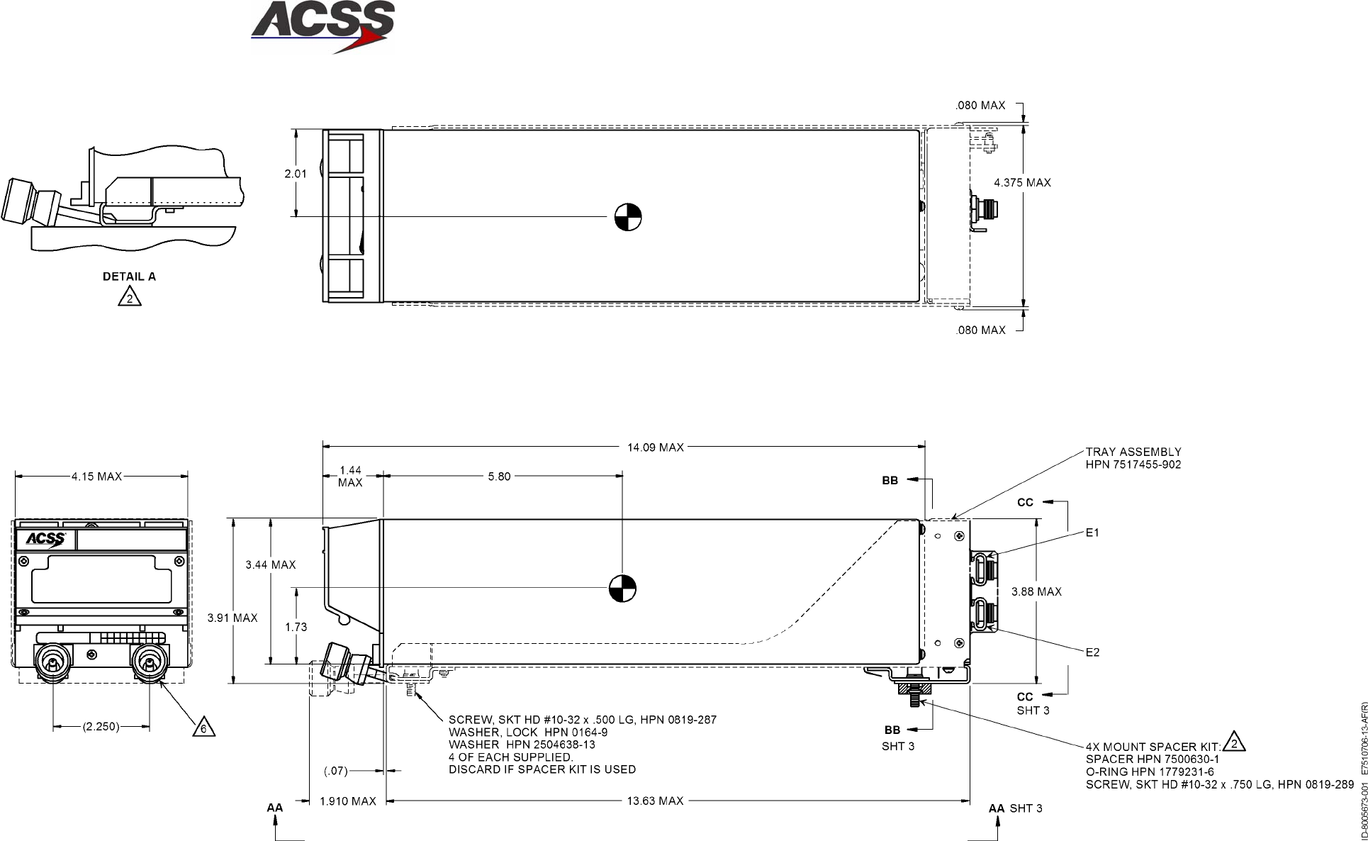
SYSTEM DESCRIPTION AND INSTALLATION MANUAL
TCAS 3000 Traffic Alert and Collision Avoidance System
34−43−23
Use or disclosure of information on this page is subject to the restrictions in the proprietary notice of this document.
Page 2−53/(2−54 blank)
15 Dec 2005
Figure 2−14 (Sheet 1). RCZ−852 Mode S Transponder Outline and Installation Diagram
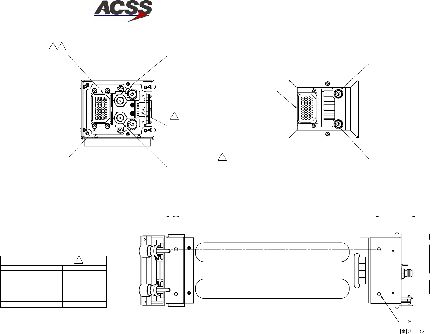
SYSTEM DESCRIPTION AND INSTALLATION MANUAL
TCAS 3000 Traffic Alert and Collision Avoidance System
34−43−23
Use or disclosure of information on this page is subject to the restrictions in the proprietary notice of this document.
Page 2−55/(2−56 blank)
15 Dec 2005
57
4 X .206
.200
.014 M
11
11
W1P1−1J1−104 W1W1 (GRN)
W1W2 (ORN)J1−92W1P1−2
FROM TO WIRE
W1W3 (RED)
J1−90W1P1−3
W1W4 (BLK)J1−103W1P1−4
W1W6 (BLU)J1−91W1P1−6
W1W7 (WHT)J1−93W1P1−7
W1W8 (YEL)J1−105W1P1−8
5
.575 11.750
.880
2.600
112
106
94
TERMINATION TABLE
2.00 MAX
A5P1 RF CONNECTOR
HPN 7500335−012
J3 RF CONNECTOR
P/O HPN 7517437−901
MATES WITH CUSTOMER
SUPPLIED TNC PLUG
A3P1 CONNECTOR
HPN 7500295−106
A5P2 RF CONNECTOR
HPN 7500335−012
J2 RF CONNECTOR
P/O HPN 7517437−901
MATES WITH CUSTOMER
SUPPLIED TNC PLUG
REAR VIEW OF RCZ−852
WITHOUT TRAY ASSY
W1 HARNESS ASSY
HPN 7510297−903
E7510706−14−AE(R)
AD−53837,SH3@
VIEW CC−CC VIEW BB−BB
VIEW AA−AA
J1 CONNECTOR
HPN 7500294−106
HEX NUT HPN 0921−001
FLAT WASHER HPN 7500501
SCREW HPN 2504188−131
SLEEVE HPN 7510288
4 REQD
Figure 2−14 (Sheet 2). RCZ−852 Mode S Transponder Outline and Installation Diagram

SYSTEM DESCRIPTION AND INSTALLATION MANUAL
TCAS 3000 Traffic Alert and Collision Avoidance System
34−43−23
Use or disclosure of information on this page is subject to the restrictions in the proprietary notice of this document.
Page 3−1
15 Dec 2005
ELECTRICAL INSTALLATION
1. General
This section gives electrical installation procedures, power distribution, and interconnect
information for each component on the TCAS 3000 system.
2. Equipment and Materials
For new TCAS 3000 installations, refer to Table 1−1 for RCZ−852 Transponder Installation Kit
information. For all other components, refer to the applicable Outline and Installation Diagram
in the MECHANICAL INSTALLATION section for mating connector part numbers.
3. Electrical Installation Procedure
The information necessary to provide the electrical interconnections is contained in the
following paragraphs. Refer to Section 4, LOADING/GRADIENT SPECIFICATIONS, for a list
of the signal names used in the interconnect diagrams and tables.
4. Electrical Installation
A. TCAS 3000 Computer Units
Figure 3−1 shows some general types of TCAS system installations, using various
combinations of controllers (control panels) and transponders.
The electrical installation of the TCAS Computer Units is detailed in Figure 3−2. The
various installation options require different electrical connections as described on the
interconnect diagram and the paragraphs that follow.
The TCAS Computer Unit uses programming and configuration straps to select or
deselect various TCAS functions. Refer to the notes in Figure 3−2 to determine
applicable installation wiring.
The TCAS Computer Unit ARINC 600 connector layout is shown in Figure 3−3. The
contact arrangement for the various connector plugs are shown in Figure 3−4 thru
Figure 3−8. Figure 3−9 shows the connector pin layout for the DATA LOADER connector
located on the front of the computer unit.
B. TCAS Antennas
The electrical installation for the TCAS antennas is shown in Figure 3−2. Figure 3−4
shows the TCAS computer contact arrangement for the top directional antenna and
Figure 3−5 shows the TCAS computer contact arrangement for the bottom antenna.
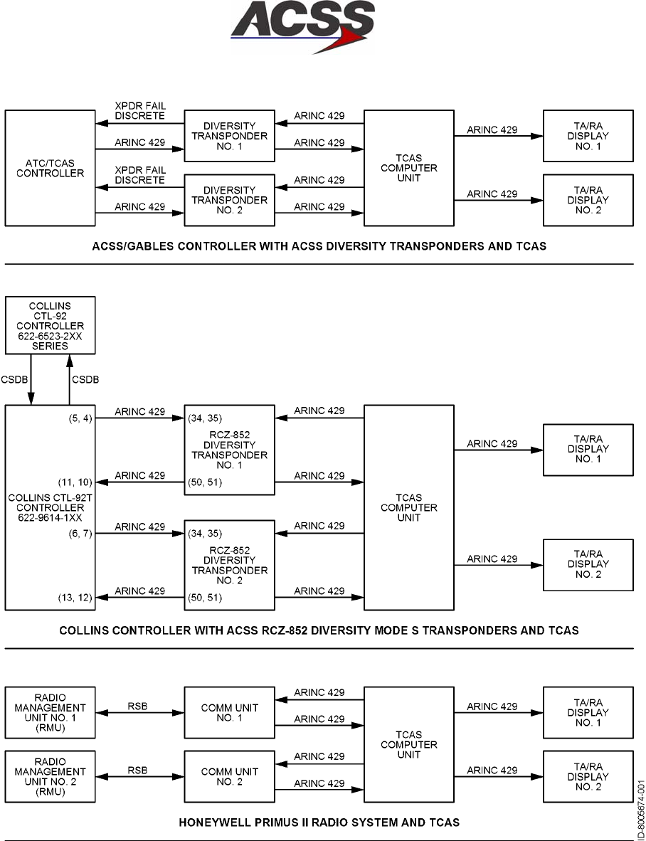
SYSTEM DESCRIPTION AND INSTALLATION MANUAL
TCAS 3000 Traffic Alert and Collision Avoidance System
34−43−23
Use or disclosure of information on this page is subject to the restrictions in the proprietary notice of this document.
Page 3−2
15 Dec 2005
Figure 3−1. Typical Installation Types
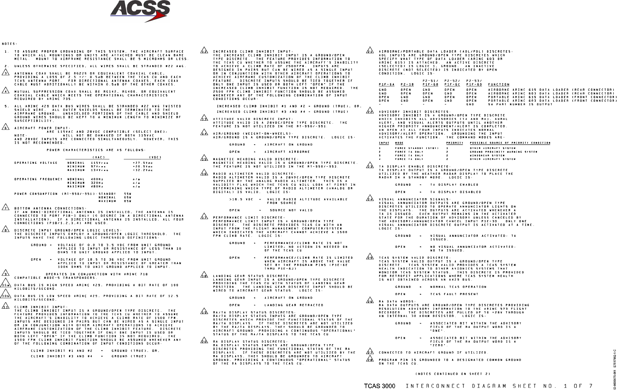
SYSTEM DESCRIPTION AND INSTALLATION MANUAL
TCAS 3000 Traffic Alert and Collision Avoidance System
34−43−23
Use or disclosure of information on this page is subject to the restrictions in the proprietary notice of this document.
Page 3−3/(3−4 blank)
15 Dec 2005
Figure 3−2 (Sheet 1). TCAS System Interconnect Diagram
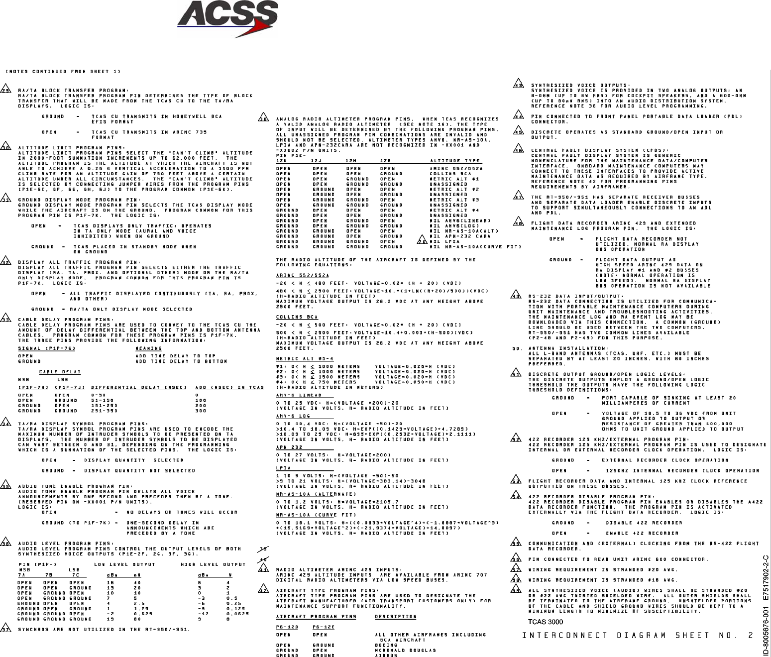
SYSTEM DESCRIPTION AND INSTALLATION MANUAL
TCAS 3000 Traffic Alert and Collision Avoidance System
34−43−23
Use or disclosure of information on this page is subject to the restrictions in the proprietary notice of this document.
Page 3−5/(3−6 blank)
15 Dec 2005
Figure 3−2 (Sheet 2). TCAS System Interconnect Diagram
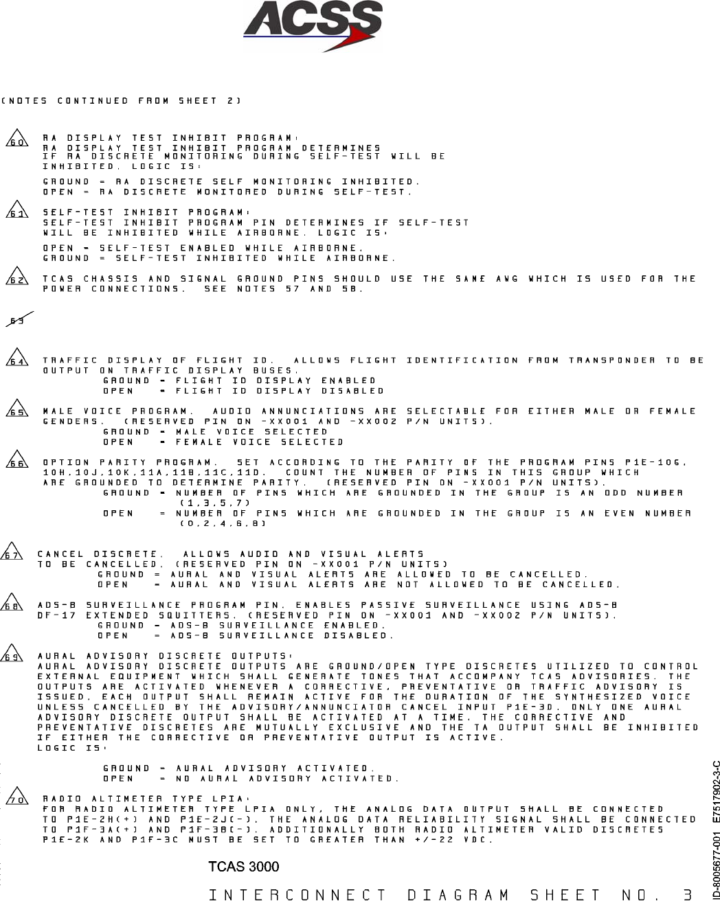
SYSTEM DESCRIPTION AND INSTALLATION MANUAL
TCAS 3000 Traffic Alert and Collision Avoidance System
34−43−23
Use or disclosure of information on this page is subject to the restrictions in the proprietary notice of this document.
Page 3−7/(3−8 blank)
15 Dec 2005
Figure 3−2 (Sheet 3). TCAS System Interconnect Diagram
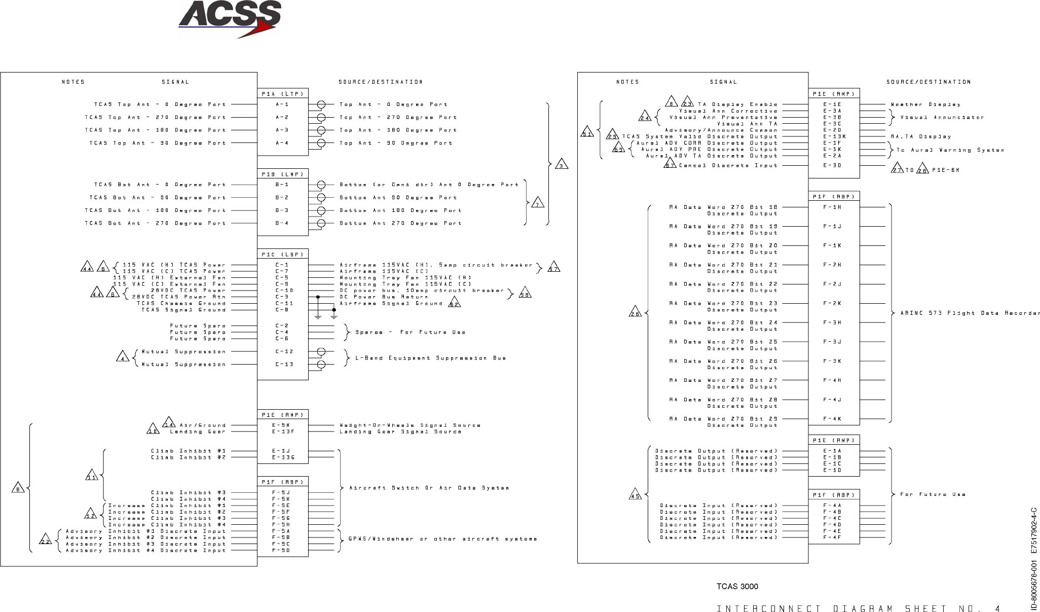
SYSTEM DESCRIPTION AND INSTALLATION MANUAL
TCAS 3000 Traffic Alert and Collision Avoidance System
34−43−23
Use or disclosure of information on this page is subject to the restrictions in the proprietary notice of this document.
Page 3−9/(3−10 blank)
15 Dec 2005
Figure 3−2 (Sheet 4). TCAS System Interconnect Diagram
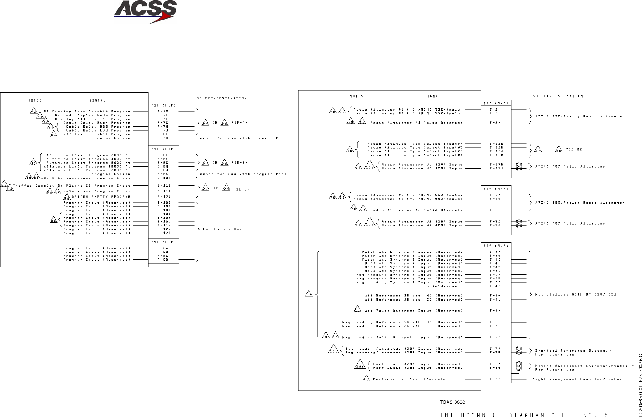
SYSTEM DESCRIPTION AND INSTALLATION MANUAL
TCAS 3000 Traffic Alert and Collision Avoidance System
34−43−23
Use or disclosure of information on this page is subject to the restrictions in the proprietary notice of this document.
Page 3−11/(3−12 blank)
15 Dec 2005
Figure 3−2 (Sheet 5). TCAS System Interconnect Diagram
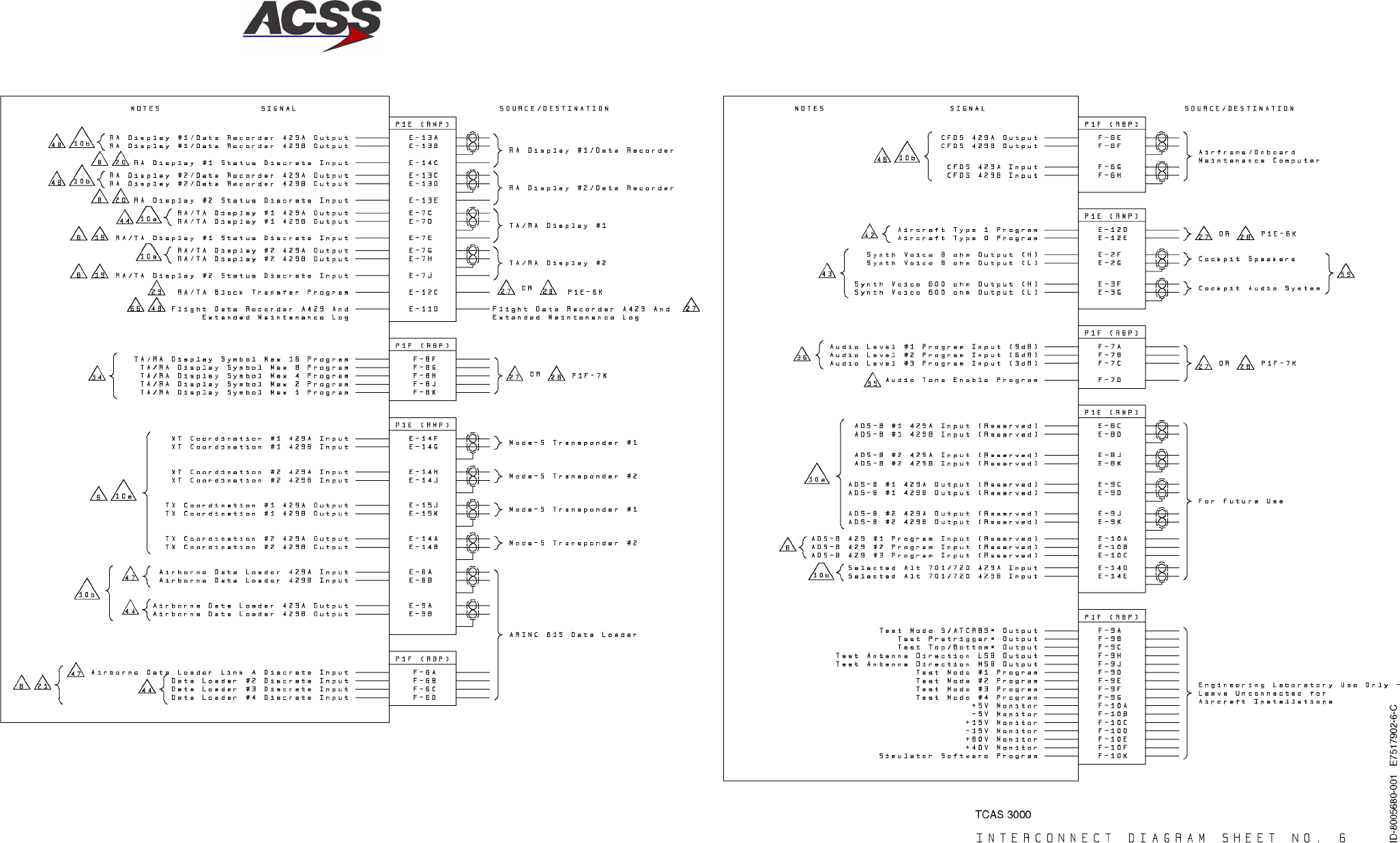
SYSTEM DESCRIPTION AND INSTALLATION MANUAL
TCAS 3000 Traffic Alert and Collision Avoidance System
34−43−23
Use or disclosure of information on this page is subject to the restrictions in the proprietary notice of this document.
Page 3−13/(3−14 blank)
15 Dec 2005
Figure 3−2 (Sheet 6). TCAS System Interconnect Diagram
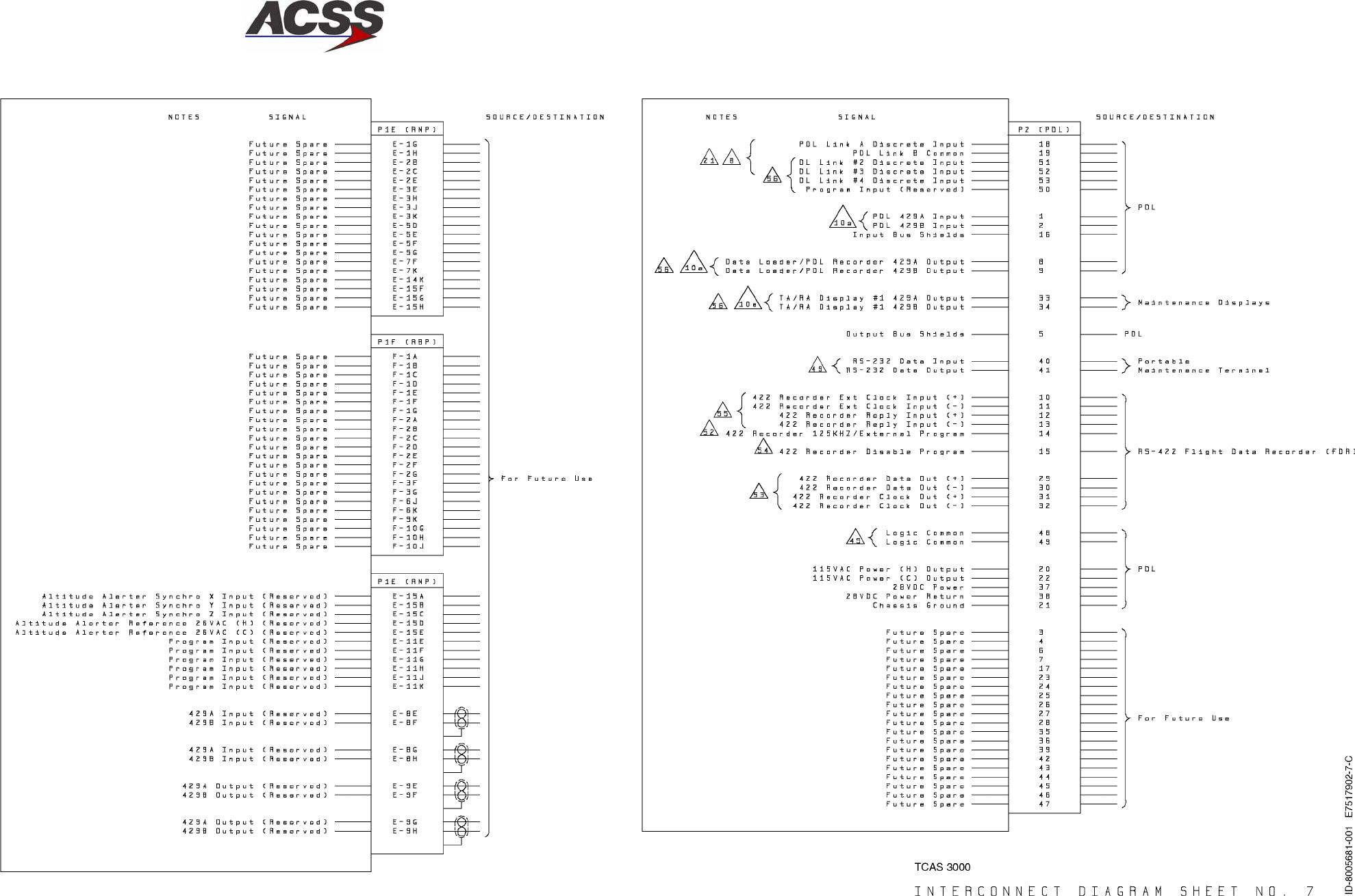
SYSTEM DESCRIPTION AND INSTALLATION MANUAL
TCAS 3000 Traffic Alert and Collision Avoidance System
34−43−23
Use or disclosure of information on this page is subject to the restrictions in the proprietary notice of this document.
Page 3−15/(3−16 blank)
15 Dec 2005
Figure 3−2 (Sheet 7). TCAS System Interconnect Diagram
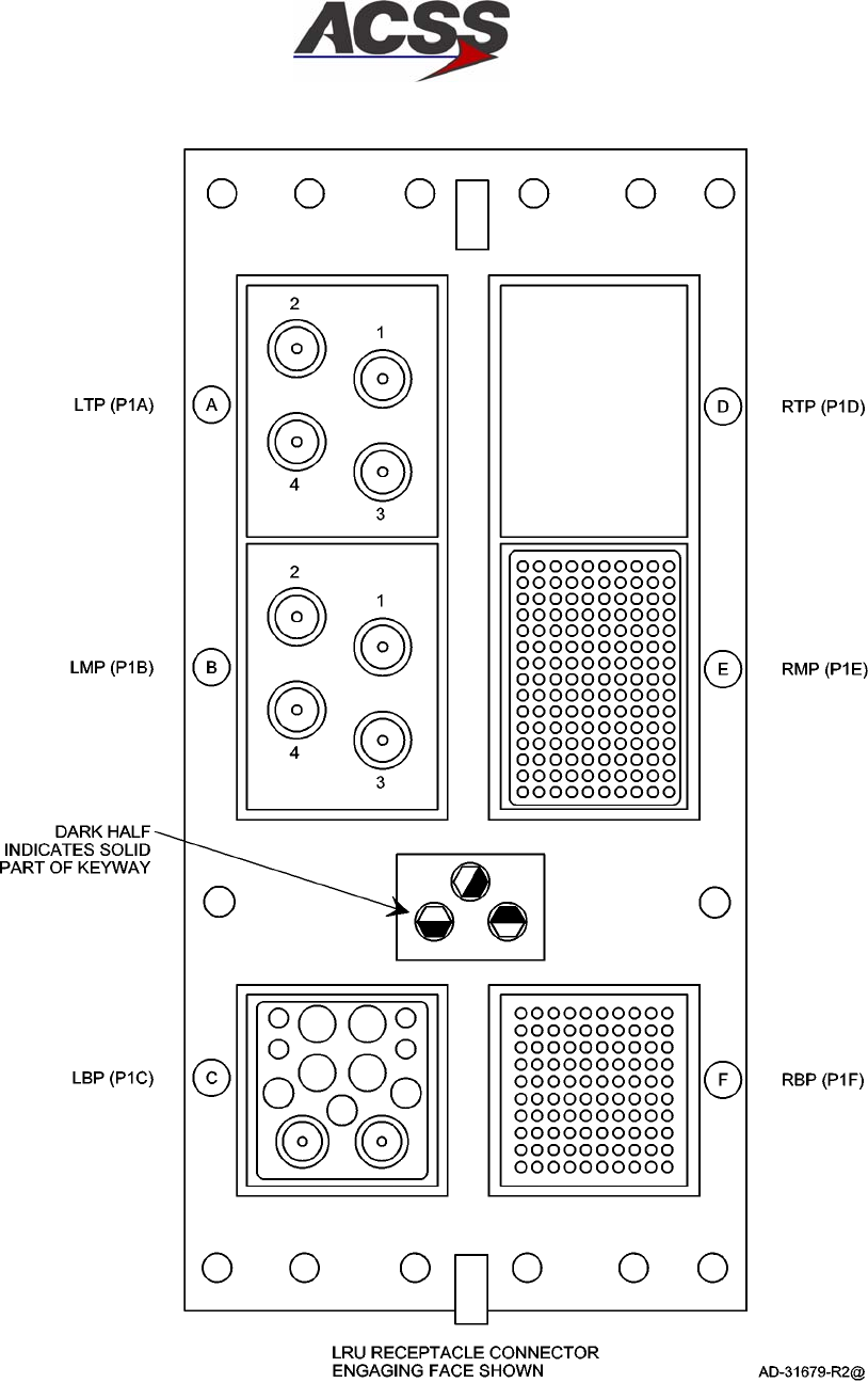
SYSTEM DESCRIPTION AND INSTALLATION MANUAL
TCAS 3000 Traffic Alert and Collision Avoidance System
34−43−23
Use or disclosure of information on this page is subject to the restrictions in the proprietary notice of this document.
Page 3−17
15 Dec 2005
Figure 3−3. TCAS 3000 Computer Unit ARINC 600 Connector (P1) Layout
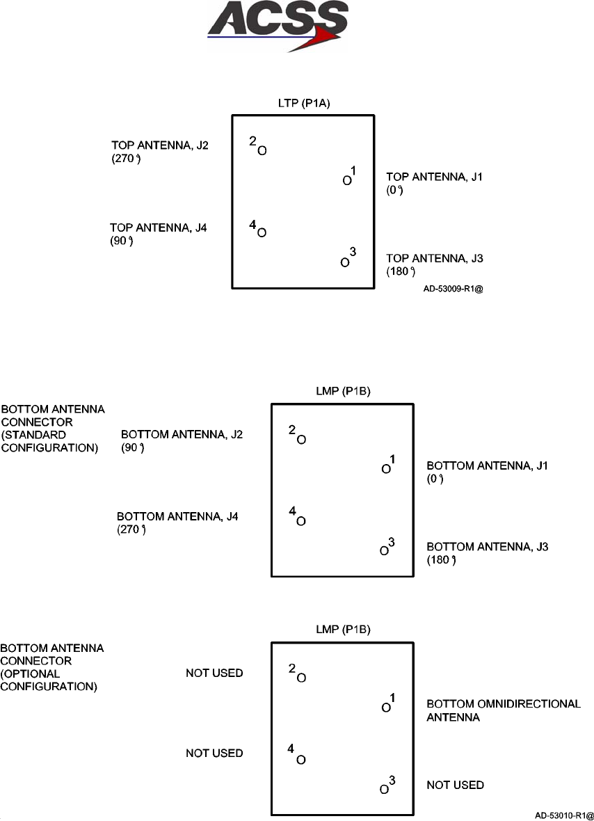
SYSTEM DESCRIPTION AND INSTALLATION MANUAL
TCAS 3000 Traffic Alert and Collision Avoidance System
34−43−23
Use or disclosure of information on this page is subject to the restrictions in the proprietary notice of this document.
Page 3−18
15 Dec 2005
Figure 3−4. Contact Arrangement for CU Left Top Plug (LTP) Insert
Figure 3−5. Contact Arrangement for CU Left Middle Plug (LMP) Insert
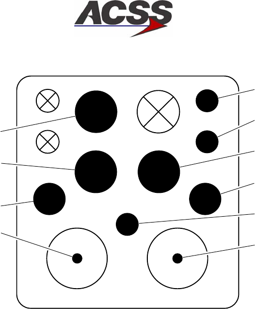
SYSTEM DESCRIPTION AND INSTALLATION MANUAL
TCAS 3000 Traffic Alert and Collision Avoidance System
34−43−23
Use or disclosure of information on this page is subject to the restrictions in the proprietary notice of this document.
Page 3−19
15 Dec 2005
SUPPRESSION
PULSE
ID−39562
SUPPRESSION
PULSE
CHASSIS GND
115 V AC FAN (C)
115 V AC POWER (C)
115 V AC FAN (H)
115 V AC POWER (H)
28 V DC POWER
SIGNAL GND
28 V DC POWER
RETURN
4
6
1
5
3
8
2
7
10 9
11
13 12
Figure 3−6. Contact Arrangement for Left Bottom Plug (LBP) Insert
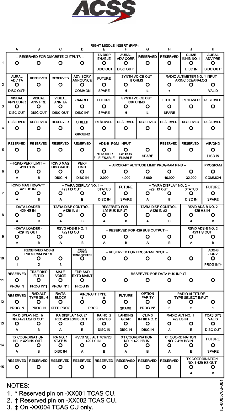
SYSTEM DESCRIPTION AND INSTALLATION MANUAL
TCAS 3000 Traffic Alert and Collision Avoidance System
34−43−23
Use or disclosure of information on this page is subject to the restrictions in the proprietary notice of this document.
Page 3−20
15 Dec 2005
Figure 3−7. Contact Arrangement for Right Middle Plug (RMP) Insert
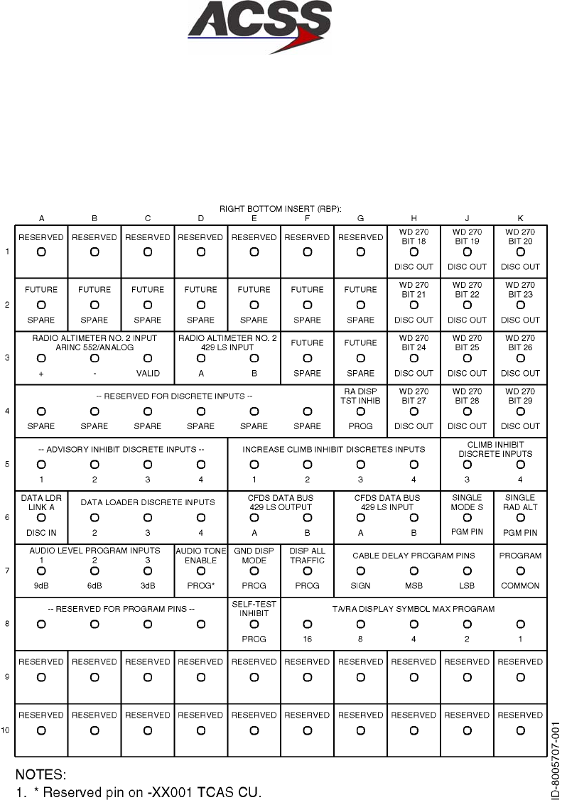
SYSTEM DESCRIPTION AND INSTALLATION MANUAL
TCAS 3000 Traffic Alert and Collision Avoidance System
34−43−23
Use or disclosure of information on this page is subject to the restrictions in the proprietary notice of this document.
Page 3−21
15 Dec 2005
Figure 3−8. Contact Arrangement for Right Bottom Plug (RBP) Insert
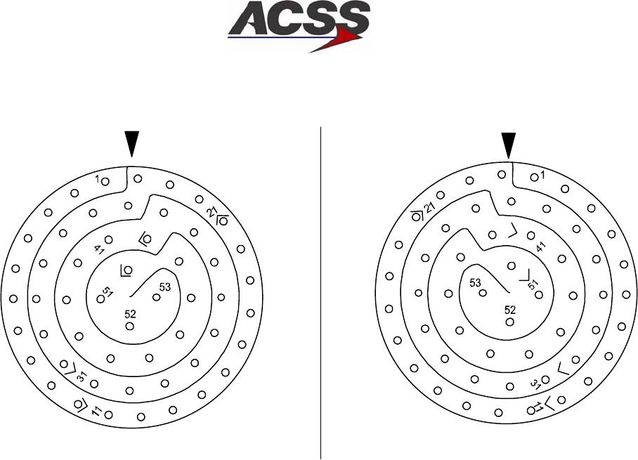
SYSTEM DESCRIPTION AND INSTALLATION MANUAL
TCAS 3000 Traffic Alert and Collision Avoidance System
34−43−23
Use or disclosure of information on this page is subject to the restrictions in the proprietary notice of this document.
Page 3−22
15 Dec 2005
NOTE: VIEWS SHOWN ARE OF MATING SURFACES AD−53014@
J2 P2
TCAS COMPUTER UNIT
DATA LOADER CONNECTOR DATA LOADER
MATING CONNECTOR
Figure 3−9. TCAS 3000 Computer Unit Data Loader Connector (J1) Pin Layout

SYSTEM DESCRIPTION AND INSTALLATION MANUAL
TCAS 3000 Traffic Alert and Collision Avoidance System
34−43−23
Use or disclosure of information on this page is subject to the restrictions in the proprietary notice of this document.
Page 3−23
15 Dec 2005
C. Control Panels
Table 3−1 thru Table 3−3 contain interconnect information for the various control panels.
Table 3−1 contains the interconnect data for the ACSS Dual Mode S/TCAS Control Panel,
Part No. 4052190−902, −904, −906 and −908. Table 3−2 contains the interconnect data
for the ACSS ATCRBS−Mode S/TCAS Control Panel, Part No. 4052190−903, −905, −907
and −909. Table 3−3 contains the interconnect data for the Gables G7130 series control
panels.
Table 3−1. ACSS Dual Mode S Control Panel Interconnect Data
I/O Description
Connector
Pin Connects To Notes
(I) 5 V ac Panel Lighting (C) J1−1 (20) Acft Lighting Source
(I) 5 V ac Panel Lighting (H) J1−2 (20) Acft Lighting Source
(I) 115 V ac Input Power (H) J1−3 (20) Acft 115 V ac Supply
(I) 115 V ac Return (C) J1−4 (20) Acft ac Ground
(O) Antenna Transfer Discrete J1−5 (22) Antenna Relay 1
(I) dc Ground J1−6 (22) Acft dc Ground
(O) Standby/On J1−7 (22) Transponder No.1
(I) Chassis Ground J1−8 (22) Airframe Ground 2
(I) Functional Test J1−9 (22) Remote Test Switch
(O) Warning & Caution J1−10 (22) Remote Warn System
Spare J1−11
(I) XPDR Fail No.2 Input J1−12 (22) Transponder No.1
Spare J1−13
Spare J1−14
Reserved J1−15
(O) Alt Source Select Discrete J1−16 (22) Transponder No.1
Spare J1−17
(I) Monitor Lamp Pwr J1−18 (20) 28 V dc, 2A Source
Spare J1−19
(I) XPDR Fail No.1 Input J1−20 (22) See J1−12 4
(I) Lamp Test J1−21 (22) Rmt Lamp Test Switch
(O) ARINC 429 (A) Out J1−22 (22) S T S
||
Transponder No.1 3
(O) ARINC 429 (B) Out J1−23 (22) STS
GND ll
GND
Transponder No.1 3

SYSTEM DESCRIPTION AND INSTALLATION MANUAL
TCAS 3000 Traffic Alert and Collision Avoidance System
34−43−23
Use or disclosure of information on this page is subject to the restrictions in the proprietary notice of this document.
Page 3−24
15 Dec 2005
Table 3−1. ACSS Dual Mode S Control Panel Interconnect Data (cont)
I/O NotesConnects To
Connector
Pin
Description
Reserved J1−24
Spare J2−1
Spare J2−2
(I) 115 V ac Input Power (H) J2−3 (20) Acft 115 V ac Supply
(I) 115 V ac Return (C) J2−4 (20) Acft ac Ground
(O) Antenna Transfer Discrete J2−5 (22) Antenna Relay 1
(I) dc Ground J2−6 (22) Acft dc Ground
(O) Standby/On Discrete J2−7 (22) Transponder No.2
(I) Chassis Ground J2−8 (22) Airframe Ground 2
Spare J2−9
Spare J2−10
Spare J2−11
(I) XPDR Fail No.2 Input J2−12 (22) Transponder No.2
Spare J2−13
Spare J2−14
Reserved J2−15
(O) Alt Source Select Discrete J2−16 (22) Transponder No.2
Spare J2−17
Spare J2−18
Spare J2−19
(I) XPDR Fail No.1 Input J2−20 (22) See J2−12 4
Spare J2−21
(O) ARINC 429 (A) Out J2−22 (22) S T S
||
Transponder No.2 3
(O) ARINC 429 (B) Out J2−23 (22) STS
GND ll
GND
Transponder No.2 3

SYSTEM DESCRIPTION AND INSTALLATION MANUAL
TCAS 3000 Traffic Alert and Collision Avoidance System
34−43−23
Use or disclosure of information on this page is subject to the restrictions in the proprietary notice of this document.
Page 3−25
15 Dec 2005
Table 3−1. ACSS Dual Mode S Control Panel Interconnect Data (cont)
I/O NotesConnects To
Connector
Pin
Description
Reserved J2−24
NOTES:
1. Connect either J1−5 or J2−5 to an antenna switching relay if one set of ATC antennas is used in a
dual transponder installation.
2. Tie chassis ground to aircraft frame.
3. Two wire shielded cable. Tie shields to aircraft dc ground.
4. Connector pins J1−12 and J1−20 and pins J2−12 and J2−20 are tied together in the controller.

SYSTEM DESCRIPTION AND INSTALLATION MANUAL
TCAS 3000 Traffic Alert and Collision Avoidance System
34−43−23
Use or disclosure of information on this page is subject to the restrictions in the proprietary notice of this document.
Page 3−26
15 Dec 2005
Table 3−2. ACSS ATCRBS−Mode S Control Panel Interconnect Data
I/O Description
Connector
Pin Connects To Notes
(I) 5 V ac Pnl Lighting (C) J1−1 (20) Acft Lighting Source
(I) 5 V ac Pnl Lighting (H) J1−2 (20) Acft Lighting Source
(I) 115 V ac Input Power (H) J1−3 (20) Acft 115V ac Supply
(I) 115 V ac Return (C) J1−4 (20) Acft ac Ground
(O) Antenna Transfer Discrete J1−5 (22) Antenna Relay 1
(I) dc Ground J1−6 (22) Acft dc Ground
(O) Standby/On J1−7 (22) Mode S Transponder
(I) Chassis Ground J1−8 (22) Airframe Ground 2
(I) Functional Test J1−9 (22) Remote Test Switch
(O) Warning & Caution J1−10 (22) Remote Warn System
Spare J1−11
(I) XPDR Fail No.2 Input J1−12 (22) Mode S Transponder
Spare J1−13
Spare J1−14
Reserved J1−15
(O) Alt Source Select Discrete J1−16 (22) Mode S Transponder
Spare J1−17
(I) Monitor Lamp Power J1−18 (20) 28 V dc, 2A Source
Spare J1−19
(I) XPDR Fail No.1 Input J1−20 (22) See J1−12 4
(I) Lamp Test J1−21 (22) Rmt Lamp Test Switch
(O) ARINC 429 (A) Out J1−22 (22) S T S
||
Mode S Transponder 3
(O) ARINC 429 (B) Out J1−23 (22) S T S
GND ll
GND
Mode S Transponder 3
Reserved J1−24
Spare J2−A
Spare J2−B
Spare J2−C
Spare J2−D

SYSTEM DESCRIPTION AND INSTALLATION MANUAL
TCAS 3000 Traffic Alert and Collision Avoidance System
34−43−23
Use or disclosure of information on this page is subject to the restrictions in the proprietary notice of this document.
Page 3−27
15 Dec 2005
Table 3−2. ACSS ATCRBS−Mode S Control Panel Interconnect Data (cont)
I/O NotesConnects To
Connector
Pin
Description
Spare J2−E
Spare J2−F
Spare J2−G
Spare J2−H
Spare J2−J
Spare J2−K
(O) Alt No. 1 J2−L (22) Altitude Digitizer No. 1
Spare J2−M
(O) Alt No. 2 J2−N (22) Altitude Digitizer No. 2
Spare J2−P
(O) Altitude Common J2−R (22) ATCRBS Transponder
Spare J2−S
(O) Transponder No. 2 On J2−T (22) ATCRBS Transponder
Spare J2−U
Spare J2−V
Spare J2−W
(O) Mode A Reply Pulse (A1) J2−X (22) ATCRBS Transponder
(O) Mode A Reply Pulse (A2) J2−Y (22) ATCRBS Transponder
(O) Mode A Reply Pulse (A4) J2−Z (22) ATCRBS Transponder
(O) Mode A Reply Pulse (B1) J2−a (22) ATCRBS Transponder
(O) Mode A Reply Pulse (B2) J2−b (22) ATCRBS Transponder
(O) Mode A Reply Pulse (B4) J2−c (22) ATCRBS Transponder
(O) Mode A Reply Pulse (C1) J2−d (22) ATCRBS Transponder
(O) Mode A Reply Pulse (C2) J2−e (22) ATCRBS Transponder
(O) Mode A Reply Pulse (C4) J2−f (22) ATCRBS Transponder
(O) Mode A Reply Pulse (D1) J2−g (22) ATCRBS Transponder
(O) Mode A Reply Pulse (D2) J2−h (22) ATCRBS Transponder
(O) Mode A Reply Pulse (D4) J2−i (22) ATCRBS Transponder
(O) Ident Output J2−j (22) ATCRBS Transponder
Spare J2−k
(I) ATC Fail J2−m (22) ATCRBS Transponder
SYSTEM DESCRIPTION AND INSTALLATION MANUAL
TCAS 3000 Traffic Alert and Collision Avoidance System
34−43−23
Use or disclosure of information on this page is subject to the restrictions in the proprietary notice of this document.
Page 3−28
15 Dec 2005
Table 3−2. ACSS ATCRBS−Mode S Control Panel Interconnect Data (cont)
I/O NotesConnects To
Connector
Pin
Description
(I) dc Ground J2−n (22) Acft dc Ground
Spare J2−p
Spare J2−q
(O) Alt Rptg On J2−r (22) ATCRBS Transponder
(O) Test Output J2−s (22) ATCRBS Transponder
(O) Transponder No. 1 On J2−tNC
NOTES:
1. Connect to antenna coax switching relay if one set of ATC antennas is used in a dual transponder
installation.
2. Tie chassis ground to aircraft frame.
3. Two wire shielded cable. Tie shields to aircraft dc ground.
4. Connector pins J1−12 and J1−20 are tied together in the Control Panel.

SYSTEM DESCRIPTION AND INSTALLATION MANUAL
TCAS 3000 Traffic Alert and Collision Avoidance System
34−43−23
Use or disclosure of information on this page is subject to the restrictions in the proprietary notice of this document.
Page 3−29
15 Dec 2005
Table 3−3. Gables G7130−XX ATC/TCAS Control Panel Interconnect Data
I/O Description
Connector
Pin Connects To Notes
(I) 5 V ac Pnl Lighting (H) J1−1 (20) Acft Lighting Source
(I) 5 V ac Pnl Lighting (L) J1−2 (20) Acft Lighting Source
(I) +28 V dc Input Power (H) J1−3 (20) Acft 28 V dc Power
(I) +28 V dc Return (L) J1−4 (20) Acft dc Ground
(O) Antenna Transfer Discrete J1−5 (22) Antenna Relay 1, 2
(I) dc Ground J1−6 (22) Acft dc Ground
(O) Standby/On Output Disc J1−7 (22) Transponder No. 1
(I) Chassis Ground J1−8 (22) Airframe Ground 3
(I) Functional Test J1−9 (22) Remote Test Switch
(O) Warning & Caution J1−10 (22) Remote Warn Sys 2
Reserved J1−11
(I) XPDR Fail Logic No.2 J1−12 (22) Transponder No. 1
(I) Ident Input J1−13 (22) Remote IDENT Switch 2
(I) XPDR Fail (High Level) J1−14 NC 2, 4
(O) Air/Gnd Switched Discrete J1−15 NC
(O) Alt Source Select Discrete J1−16 (22) Transponder No.1 2
Reserved J1−17
(I) Monitor Lamp Power J1−18 (20) Acft 28 V dc Power
Reserved J1−19
(I) XPDR Configuration J1−20 NC 2
(I) Lamp Test J1−21 (22) Rmt Lamp Test SW 2
(O) ARINC 429 (A) Out J1−22 (22) S T S
||
Transponder No.1 5
(O) ARINC 429 (B) Out J1−23 (22) S T S
GND ll
GND
Transponder No.1 5
(I) Air/Gnd Discrete J1−24 (22) WOW Switch 2
Reserved J2−1
Reserved J2−2
(I) +28V dc Input Power (H) J2−3 (20) Acft 28 V dc Power
(I) +28V dc Return (L) J2−4 (20) Acft dc Ground

SYSTEM DESCRIPTION AND INSTALLATION MANUAL
TCAS 3000 Traffic Alert and Collision Avoidance System
34−43−23
Use or disclosure of information on this page is subject to the restrictions in the proprietary notice of this document.
Page 3−30
15 Dec 2005
Table 3−3. Gables G7130−XX ATC/TCAS Control Panel Interconnect Data (cont)
I/O NotesConnects To
Connector
Pin
Description
(O) Antenna Transfer Discrete J2−5 (22) Antenna Relay 1, 2
(I) dc Ground J2−6 (22) Acft dc Ground
(O) Standby/On Discrete J2−7 (22) Transponder No.2
(I) Chassis Ground J2−8 (22) Airframe Ground 3
(I) Functional Test J2−9 (22) Remote Test SW
(O) Warning & Caution J2−10 (22) Remote Warn Sys 2
Reserved J2−11
(I) XPDR Fail Logic No.2 J2−12 (22) Transponder No.2
(I) Ident Input J2−13 (22) Remote Ident SW 2
(I) XPDR Fail (High Level) J2−14 NC 2, 4
(O) Air/Gnd Switched Discrete J2−15 (22) NC
(O) Alt Source Select Discrete J2−16 (22) Transponder No.2 2
Reserved J2−17
(I) Monitor Lamp Pwr J2−18 (20) Acft 28 V dc Power 2
Reserved J2−19
(I) XPDR Configuration J2−20 NC Gnd/Open 2
(I) Lamp Test J2−21 (22) Rmt Lamp Test SW 2
(O) ARINC 429 (A) Out J2−22 (22) S T S
||
Transponder No.2 5
(O) ARINC 429 (B) Out J2−23 (22) S T S
GND ll
GND
Transponder No.2 5
(I) Air/Gnd Discrete J2−24 (22) Acft WOW Switch 2
NOTES:
1. Connect either J1−5 or J2−5 to an antenna switching relay if one set of ATC antennas is used in a
dual transponder installation.
2. Refer to Loading Gradient Specifications in Table 4−4.
3. Tie chassis ground to aircraft frame.
4. 28 V dc discrete input from Collins TDR−94D transponder.
5. Two wire shielded cable. Tie shields to aircraft dc ground.

SYSTEM DESCRIPTION AND INSTALLATION MANUAL
TCAS 3000 Traffic Alert and Collision Avoidance System
34−43−23
Use or disclosure of information on this page is subject to the restrictions in the proprietary notice of this document.
Page 3−31
15 Dec 2005
D. VSI/TRA Displays
Table 3−4 and Table 3−5 contain the interface information for the various ACSS VSI/TRA
displays. Table 3−4 contains interconnect data for the 41−pin connector units. Table 3−5
contains the interconnect data for the 55−pin connector (bootstrap) units.
Figure 3−10 and Figure 3−11 show the connector pin layouts for the VSI/TRA.
Figure 3−10 shows the 41−pin connector configuration and Figure 3−11 shows the 55−pin
connector configuration.
Table 3−4. 41−Pin VSI/TRA Interconnect Data
I/O Description
Connector
Pin Connects To Notes
(I) VS +dc Ref J1−1 (22) ARINC 575 ADC
(I) VS dc Rate J1−2 (22) ARINC 575 ADC
(I) VS −dc Ref J1−3 (22) ARINC 575 ADC
(I) Primary VS (HI) J1−4 (22) S T S
||
ARINC 565 ADC or
IRS
1
(I) Primary VS (LO) J1−6 (22) S T S
GND ll
GND
ARINC 565 ADC or
IRS
1
(I) VS 26 V ac Ref (HI) J1−5 (22) ARINC 565 ADC or
IRS
(I) Reserved ARINC Bus (A) J1−7
(I) Reserved ARINC Bus (B) J1−21
(I) VS VALID NO.1 J1−8 (22) ARINC 565/575 ADC
or IRS
(I) 5 V Lamp Dimming (LO) J1−9 (22) Acft Lamp Dim Ckt
(I) 5 V Lamp Dimming (HI) J1−10 (22) Acft Lamp Dim Ckt
(I) TCAS TA/RA
ARINC 429 (B)
J1−11 (22) S T S
||
TCAS Computer 1
(I) TCAS TA/RA
ARINC 429 (A)
J1−26 (22) S T S
GND ll
GND
TCAS Computer 1
(I) VS No.1 ARINC 429 (B) J1−12 (22) S T S
||
Digital ADC No.1 or
PTM No.1
1
(I) VS No.1 ARINC 429 (A) J1−27 (22) S T S
GND ll
GND
Digital ADC No.1 or
PTM No.1
1
Spare J1−13

SYSTEM DESCRIPTION AND INSTALLATION MANUAL
TCAS 3000 Traffic Alert and Collision Avoidance System
34−43−23
Use or disclosure of information on this page is subject to the restrictions in the proprietary notice of this document.
Page 3−32
15 Dec 2005
Table 3−4. 41−Pin VSI/TRA Interconnect Data (cont)
I/O NotesConnects To
Connector
Pin
Description
(I) VS No.2 ARINC 429 (B) J1−14 (22) STS
||
Digital ADC No.2 or
PTM No.2
(I) VS No.2 ARINC 429 (A) J1−30 (22) S T S
GND ll
GND
Digital ADC No.2 or
PTM No.2
(I) Config Strap Common J1−15 (22) Config Strap Logic
Gnd
5
(I) VS 26 V ac Ref (C) J1−16 (22) ARINC 565 ADC or
IRS
(I) Config Strap No.3 (CS3) J1−17 (22) Gnd/Open
(O) PTM Common J1−18 (20) S T S
||
Pressure Xdcr Mdl 2
(O) PTM Pwr Out (−15 V dc) J1−19 (20) S T S
||
Pressure Xdcr Mdl 2
(O) PTM Pwr Out (+15 V dc) J1−20 (20) S T S
GND ll
GND
Pressure Xdcr Mdl 2
(I) Chassis Ground J1−22 (22) Airframe Ground 3
(I) 115 V ac Return (C) J1−23 (20) Acft ac Ground
(I) Remote Light Sensor (LO) J1−24 (22) S T S
||
Acft Rmt Light Sensor 1
(I) Remote Light Sensor (HI) J1−25 (22) S T S
GND ll
GND
Acft Rmt Light Sensor 1
Spare J1−28
(O) RA Valid Out J1−29 (22) TCAS Computer
(I) Source Sel Discrete In J1−31 (22) Gnd/Open
(I) Config Strap No.0 (CS0) J1−32 (22) Gnd/Open
(I) Config Strap No.1 (CS1) J1−33 (22) Gnd/Open
(I) Config Strap No.2 (CS2) J1−34 (22) Gnd/Open
(I) Config Strap No.4 (CS4) J1−35 (22) Gnd/Open
(I) Config Strap No.5 (CS5) J1−36 (22) Gnd/Open
(I) Config Strap No.6 (CS6) J1−37 (22) Gnd/Open
(I) Config Strap No.7 (CS7) J1−38 (22) Gnd/Open

SYSTEM DESCRIPTION AND INSTALLATION MANUAL
TCAS 3000 Traffic Alert and Collision Avoidance System
34−43−23
Use or disclosure of information on this page is subject to the restrictions in the proprietary notice of this document.
Page 3−33
15 Dec 2005
Table 3−4. 41−Pin VSI/TRA Interconnect Data (cont)
I/O NotesConnects To
Connector
Pin
Description
(I) dc Ground J1−39 (22) Acft dc Ground
(I) 115 V ac Input Power (H) J1−40 (20) Acft 115 V ac Supply
(I) Config Strap No.8 (CS8) J1−41 (22) Gnd/Open
NOTES:
1. Two wire shielded cable. Tie shields to aircraft dc ground.
2. Three wire shielded cable. Tie shields to aircraft dc ground.
3. Tie chassis ground to aircraft frame.
SYSTEM DESCRIPTION AND INSTALLATION MANUAL
TCAS 3000 Traffic Alert and Collision Avoidance System
34−43−23
Use or disclosure of information on this page is subject to the restrictions in the proprietary notice of this document.
Page 3−34
15 Dec 2005
33
34
35
36
37
38
39
40
41
22
21
20
19
18
17
16
15
32
14
31
30
13
29
28
12
27
26
11
25
10
24
9
23
8
7
2
1
3
6
5
4
AD−53015@
Figure 3−10. VSI/TRA 41−Pin Connector Layout

SYSTEM DESCRIPTION AND INSTALLATION MANUAL
TCAS 3000 Traffic Alert and Collision Avoidance System
34−43−23
Use or disclosure of information on this page is subject to the restrictions in the proprietary notice of this document.
Page 3−35
15 Dec 2005
Table 3−5. 55−Pin VSI/TRA Interconnect Data
I/O Description
Connector
Pin Connects To Notes
(I) Secondary ARINC 565 VS
(LO) Input
J1−1 (22) STS
||
Cross−Side VSI/TRA 1
(I) Secondary ARINC 565 VS
(HI) Input
J1−6 (22) S T S
GND ll
GND
Cross−Side VSI/TRA 1
(I) VS dc Rate J1−2 (22) ARINC 575 ADC
(I) VS −dc Ref J1−3 (22) ARINC 575 ADC
(O) Bootstrap Ref Output J1−4 (22) Cross−Side VSI/TRA
(I) VS No.2 Valid Discrete In J1−5 (22) Cross−Side VSI/TRA
(I) Second 26 V ac Ref In J1−7 (22) Cross−Side VSI/TRA
(I) VS +dc Ref J1−8 (22) ARINC 575 ADC
(I) Primary 26 V ac Ref (H) J1−9 (22) ARINC 565 ADC
(I) Primary VS (LO) J1−10 (22) S T S
||
ARINC 565 ADC 1
(I) Primary VS (HI) J1−11 (22) S T S
GND ll
GND
ARINC 565 ADC 1
(I) VS No.1 Valid Discrete In J1−12 (22) ARINC 565/575 ADC
(O) R/C Bootstrap (LO) Output J1−13 (22) S T S
||
Cross−Side VSI/TRA 1
(O) R/C Bootstrap (HI) Output J1−14 (22) S T S
GND ll
GND
Cross−Side VSI/TRA 1
(O) Bootstrap Command Out J1−15 NC
Spare J1−16
(I) Config Strap No.5 (CS5) J1−17 (22) Gnd/Open
(I) Config Strap No.6 (CS6) J1−18 (22) Gnd/Open
(I) Config Strap No.7 (CS7) J1−19 (22) Gnd/Open
(I) Chassis Ground J1−20 (22) Airframe Ground 2
(I) dc Ground J1−21 (22) Acft dc Ground
(I) Config Strap No.8 (CS8) J1−22 (22) Gnd/Open
(I) Remote Light Sensor (HI) J1−23 (22) S T S
||
Acft Rmt Light Sensor 2
(I) Remote Light Sensor (LO) J1−24 (22) STS
GND ll
GND
Acft Rmt Light Sensor 2

SYSTEM DESCRIPTION AND INSTALLATION MANUAL
TCAS 3000 Traffic Alert and Collision Avoidance System
34−43−23
Use or disclosure of information on this page is subject to the restrictions in the proprietary notice of this document.
Page 3−36
15 Dec 2005
Table 3−5. 55−Pin VSI/TRA Interconnect Data (cont)
I/O NotesConnects To
Connector
Pin
Description
(I) TCAS ARINC 429 (A) J1−25 (22) STS
||
TCAS Computer 2
(I) TCAS ARINC 429 (B) J1−44 (22) S T S
GND ll
GND
TCAS Computer 2
(I) VS No.2 ARINC 429 (A) J1−26 (22) S T S
||
Digital ADC No.2 or
PMT No.2
2
(I) VS No.2 ARINC 429 (B) J1−45 (22) S T S
GND ll
GND
Digital ADC No.2 or
PMT No.2
2
(I) IRS ARINC 429 (A) J1−27 (22) S T S
||
Inertial Reference Sys 2
(I) IRS ARINC 429 (B) J1−46 (22) S T S
GND ll
GND
Inertial Reference Sys 2
(O) RA Valid Discrete Out J1−28 (22) TCAS Computer
(I) Source Select No.2 J1−29 (22) Gnd/Open
Spare J1−30
(I) Source Select No.1 J1−31 (22) Gnd/Open
(I) Config Strap No.0 (CS0) J1−32 (22) Gnd/Open
(I) Config Strap No.1 (CS1) J1−33 (22) Gnd/Open
(I) Config Strap No.2 (CS2) J1−34 (22) Gnd/Open
(I) Config Strap No.3 (CS3) J1−35 (22) Gnd/Open
(I) Config Strap No.4 (CS4) J1−36 (22) Gnd/Open
(I) Config Strap Common J1−37 (22) Config Strap Logic
Gnd
(I) 115 V ac Return (C) J1−38 (20) Acft ac Ground
Spare J1−39
(I) 115 V ac Input Power (H) J1−40 (20) Acft 115 V ac Supply
Spare J1−41
(I) 5 V Lamp Dimming (HI) J1−42 (22) Acft Lamp Dim Ckt
(I) 5 V Lamp Dimming (LO) J1−43 (22) Acft Lamp Dim Ckt
(I) VS No.1 ARINC 429 (A) J1−47 (22) STS
||
Digital ADC No.1 or
PTM No.1
2
SYSTEM DESCRIPTION AND INSTALLATION MANUAL
TCAS 3000 Traffic Alert and Collision Avoidance System
34−43−23
Use or disclosure of information on this page is subject to the restrictions in the proprietary notice of this document.
Page 3−37
15 Dec 2005
Table 3−5. 55−Pin VSI/TRA Interconnect Data (cont)
I/O NotesConnects To
Connector
Pin
Description
(I) VS No.1 ARINC 429 (B) J1−48 (22) STS
GND ll
GND
Digital ADC No.1 or
PTM No.1
2
(O) VSI Valid Output Discrete J1−49 (22) Cross−Side VSI/TRA
(O) PTM Pwr Out (−15 V dc) J1−50 (20) S T S
||
Pressure Xdcr Mdl 3
(O) PTM Common J1−51 (20) S T S
||
Pressure Xdcr Mdl 3
(O) PTM Pwr Out (+15 V dc) J1−52 (20) S T S
GND ll
GND
Pressure Xdcr Mdl 3
Spare J1−53
Spare J1−54
Spare J1−55
NOTES:
1. Two wire shielded cable. Tie shields to aircraft dc ground.
2. Tie chassis ground to aircraft frame.
3. Three wire shielded cable. Tie shields to aircraft dc ground.
SYSTEM DESCRIPTION AND INSTALLATION MANUAL
TCAS 3000 Traffic Alert and Collision Avoidance System
34−43−23
Use or disclosure of information on this page is subject to the restrictions in the proprietary notice of this document.
Page 3−38
15 Dec 2005
1
2
3
45
6
7
8
9
10
11
12
13 14 15
16
17
18
19
20
21
22
23
24
25
26
27
28 29 30
31
32
33
34
35
36
37
38
39
40
41
42
43
44
45
46
47 48 49
50
51
52
53
54
55
AD−53016@
Figure 3−11. VSI/TRA 55−Pin Connector Layout

SYSTEM DESCRIPTION AND INSTALLATION MANUAL
TCAS 3000 Traffic Alert and Collision Avoidance System
34−43−23
Use or disclosure of information on this page is subject to the restrictions in the proprietary notice of this document.
Page 3−39
15 Dec 2005
E. Pressure Transducer Module
Table 3−6 contains the interconnect data for the ACSS Pressure Transducer Module
(PTM).
Table 3−6. Pressure Transducer Module Interconnect Data
I/O Description
Connector
Pin Connects To Notes
(I) Chassis Ground J1−1 (22) Airframe 1
(I) External Reset J1−2NC
(O) Fault Discrete J1−3NC
Reserved, Test Point J1−4
(I) +15 V dc Input Power J1−5 (22) S T S
||
VSI/TRA 2
(I) Power Ground J1−8 (22) S T S
||
VSI/TRA 2
(I) −15 V dc Input Power J1−11 (22) S T S
GND ll
GND
VSI/TRA 2
Reserved, Test Point J1−6
(O) ARINC 429 (A) Xmit J1−7 (22) S T S
||
VSI/TRA 3
(O) ARINC 429 (B) Xmit J1−13 (22) S T S
GND ll
GND
VSI/TRA 3
Reserved, Test Point J1−9
Reserved, Test Point J1−10
Reserved, Test Point J1−12
Reserved, Test Point J1−14
Spare J1−15
NOTES:
1. Tie chassis ground (J1−1) to aircraft frame.
2. Three wire shielded cable. Tie shields to aircraft dc ground.
3. Two wire shielded cable. Tie shields to aircraft dc ground.

SYSTEM DESCRIPTION AND INSTALLATION MANUAL
TCAS 3000 Traffic Alert and Collision Avoidance System
34−43−23
Use or disclosure of information on this page is subject to the restrictions in the proprietary notice of this document.
Page 3−40
15 Dec 2005
F. Transponders
Table 3−7 thru Table 3−10 contain the interface information for the ACSS transponders.
The transponders use altimetry data supplied in one of the following formats: ARINC 429
(from a digital ADC), ARINC 575, Synchro, or Gillham code. Altimetry data from one of
these source types must be connected to the transponder. If a single altimetry source is
used, it should be wired to both sets of transponder inputs.
All Mode S transponders require a unique 24−bit code (Mode S address) assigned to
each aircraft. For aircraft registered in the United States, it is necessary to have a
specific address code assigned. These address codes are presently issued by:
Federal Aviation Administration
FAA Aircraft Registry
P.O. Box 25504
Oklahoma City, OK 73125
Tel: (405) 954−3116
Fax: (405) 954−3548
If the aircraft is registered in a country other than the United States, contact the aviation
authority of the country in which the aircraft is registered.
The Mode S address is usually issued as an 8−digit octal number. To strap the address
code correctly, each digit must be converted to a corresponding binary number. (For
example: 7 octal = 111 binary, 1 octal = 001 binary.)
Once the 8−digit octal code is converted to a 24−bit binary number, the straps (address
pins) must be grounded or left open according to this binary number representation.
Each binary 0 represents an open strap and each binary 1 represents a grounded strap.
An example of an octal code number being converted to a binary number is shown below:
Octal address code = 1 2 3 4 5 6 7 0
In binary this number is: (MSB) 001 010 011 100 101 110 111 000 (LSB)
(1) XS−950 Data Link Transponder
Table 3−7 contains the interconnect data for the XS−950 Data Link Transponder, Part
No. 7517800−XXYYY.
If additional XS−950 Data Link Transponder installation or operational information is
required, refer to Mode S Data Link Transponder System Description and Installation
Manual, ACSS Pub. No. A09−3839−001.

SYSTEM DESCRIPTION AND INSTALLATION MANUAL
TCAS 3000 Traffic Alert and Collision Avoidance System
34−43−23
Use or disclosure of information on this page is subject to the restrictions in the proprietary notice of this document.
Page 3−41
15 Dec 2005
Table 3−7. XS−950 Data Link Transponder Interconnect Data
I/O Description
Connector
Pin Connects To Notes
(I) Mode C Pulse A1 #2 P1A−1A (22) Encoding Altm #2
(I) Mode C Pulse A2 #2 P1A−1B (22) Encoding Altm #2
(I) Mode C Pulse A4 #2 P1A−1C (22) Encoding Altm #2
(I) Mode C Pulse B1 #2 P1A−1D (22) Encoding Altm #2
(I) Mode C Pulse B2 #2 P1A−1E (22) Encoding Altm #2
(I) Mode C Pulse B4 #2 P1A−1F (22) Encoding Altm #2
(I) Mode C Pulse C1 #2 P1A−1G (22) Encoding Altm #2
(I) Mode C Pulse C2 #2 P1A−1H (22) Encoding Altm #2
(I) Mode C Pulse C4 #2 P1A−1J (22) Encoding Altm #2
(I) Mode C Pulse D2 #2 P1A−1K (22) Encoding Altm #2
(I) ARINC 429 (A) COMM A/B
Input from ADLP
or ARINC 429(A)
FMC/GNSS input
P1A−2A (22) S T S
||
Airborne Data Link
Processor
or FMC/GNSS
1
(I) ARINC 429 (B) COMM A/B
Input from ADLP
or ARINC 429(A)
FMC/GNSS input
P1A−2B (22) S T S
GND ll
GND
Airborne Data Link
Processor
or FMC/GNSS
1
(I) ARINC 429 (A) COMM C/D
Input from ADLP
or ARINC 429(A)
IRS/FMS/Data
Concentrator
P1A−2C (22) S T S
||
Airborne Data Link
Processor
or IRS/FMS/Data
Concentrator
1
(I) ARINC 429 (B) Comm C/D
Input from ADLP
or ARINC 429(A)
IRS/FMS/Data
Concentrator
P1A−2D (22) S T S
GND ll
GND
Airborne Data Link
Processor
or IRS/FMS/Data
Concentrator
1
(O) ARINC 429 (A) COMM C/D
Output to ADLP
or ARINC 429(A) General
output Bus
P1A−2E (22) S T S
||
Airborne Data Link
Processor
1
(O) ARINC 429 (B) COMM C/D
Output to ADLP
or ARINC 429(A) General
output Bus
P1A−2F (22) S T S
GND ll
GND
Airborne Data Link
Processor
1
Reserved P1A−2G
Reserved P1A−2H

SYSTEM DESCRIPTION AND INSTALLATION MANUAL
TCAS 3000 Traffic Alert and Collision Avoidance System
34−43−23
Use or disclosure of information on this page is subject to the restrictions in the proprietary notice of this document.
Page 3−42
15 Dec 2005
Table 3−7. XS−950 Data Link Transponder Interconnect Data (cont)
I/O NotesConnects To
Connector
Pin
Description
Reserved P1A−2J
(I) Mode C Pulse D4 #2 P1A−2K (22) Encoding Altm #2
Reserved P1A−3A
(O) XPDR Fail Discrete Out #2 P1A−3B (22) Control Panel
(I) Cable Delay Prog Top/Bot P1A−3C (22) Gnd/Open
(I) Cable Delay Program B P1A−3D (22) Gnd/Open
(I) Cable Delay Program A P1A−3E (22) Gnd/Open
(I) Cable Delay Prog Common P1A−3F (22) Program Logic Gnd
(I) SDI Program A P1A−3G (22) Gnd/Open
(I) SDI Program B P1A−3H (22) Gnd/Open
(I) SDI Common P1A−3J (22) Program Logic Gnd
(I) Mode C Pulse Common #2 P1A−3K (22) Encoding Altm #2
(I) Syn Alt In #1: Coarse X P1A−4A (22) ARINC 565 ADC #1
(I) Syn Alt In #1: Coarse Y P1A−4B (22) ARINC 565 ADC #1
(I) Syn Alt In #1: Coarse Z P1A−4C (22) ARINC 565 ADC #1
(I) Syn Alt In #1: 26 V Ref (H) P1A−4D (22) ARINC 565 ADC #1
(I) Syn Alt In #1: 26 V Ref (C) P1A−4E (22) ARINC 565 ADC #1
(I) Syn Alt In #1: Fine X P1A−4F (22) ARINC 565 ADC #1
(I) Syn Alt In #1: Fine Y P1A−4G (22) ARINC 565 ADC #1
(I) Syn Alt In #1: Fine Z P1A−4H (22) ARINC 565 ADC #1
(I) Syn Alt In #1: Flag P1A−4J (22) ARINC 565 ADC #1
Reserved P1A−4K (22)
(I) Max True Airspeed Prog A P1A−5A (22) Gnd/Open
(I) Max True Airspeed Prog B P1A−5B (22) Gnd/Open
(I) Max True Airspeed Prog C P1A−5C (22) Gnd/Open
(I) Max True AS Common P1A−5D (22) Program Logic Gnd
(I) ARINC 429 (A) TX Coord P1A−5E (22) S T S
||
TCAS Computer 1
(I) ARINC 429 (B) TX Coord P1A−5F (22) STS
GND ll
GND
TCAS Computer 1
SYSTEM DESCRIPTION AND INSTALLATION MANUAL
TCAS 3000 Traffic Alert and Collision Avoidance System
34−43−23
Use or disclosure of information on this page is subject to the restrictions in the proprietary notice of this document.
Page 3−43
15 Dec 2005
Table 3−7. XS−950 Data Link Transponder Interconnect Data (cont)
I/O NotesConnects To
Connector
Pin
Description
(O) ARINC 429 (A) XT Coord P1A−5G (22) STS
||
TCAS Computer 1
(O) ARINC 429 (B) XT Coord P1A−5H (22) S T S
GND ll
GND
TCAS Computer 1
(I) Air/Gnd Discrete Input #2 P1A−5J (22) Control Panel
(I) Air/Gnd Discrete Input #1 P1A−5K (22) Control Panel
(I) ARINC 429 (A) FMC
#1/General in #2
P1A−6A (22) S T S
||
FMC 1
(I) ARINC 429 (B) FMC
#1/General in #2
P1A−6B (22) S T S
GND ll
GND
FMC 1
(I) ARINC 429 (A) ADL Input P1A−6C (22) S T S
||
ARINC 615 Airborne
Data Loader
1
(I) ARINC 429 (B) ADL Input P1A−6D (22) S T S
GND ll
GND
ARINC 615 Airborne
Data Loader
1
(O) ARINC 429 (A) ADL Out P1A−6E (22) S T S
||
ARINC 615 Airborne
Data Loader
1
(O) ARINC 429 (B) ADL Out P1A−6F (22) S T S
GND ll
GND
ARINC 615 Airborne
Data Loader
1
(I) ADL Input Link A P1A−6G (22) ARINC 615 Airborne
Data Loader
(I) ARINC 575 (A) ADC In #1 P1A−6H (22) S T S
||
ARINC 575 ADC #1 1
(I) ARINC 575 (B) ADC In #1 P1A−6J (22) S T S
GND ll
GND
ARINC 575 ADC #1 1
(I) Single/Dual Antenna Prog P1A−6K (22) Gnd/Open
(I) ARINC 429 (A) Control
Data Input Port A
P1A−7A (22) S T S
||
Control Panel 1
(I) ARINC 429 (B) Control
Data Input Port A
P1A−7B (22) S T S
GND ll
GND
Control Panel 1
Reserved P1A−7C
(I) Control Data Port Select In P1A−7D (22) Gnd/Open

SYSTEM DESCRIPTION AND INSTALLATION MANUAL
TCAS 3000 Traffic Alert and Collision Avoidance System
34−43−23
Use or disclosure of information on this page is subject to the restrictions in the proprietary notice of this document.
Page 3−44
15 Dec 2005
Table 3−7. XS−950 Data Link Transponder Interconnect Data (cont)
I/O NotesConnects To
Connector
Pin
Description
(I) ARINC 429 (A) Control
Data Input Port B
P1A−7E (22) STS
||
Control Panel
(I) ARINC 429 (B) Control
Data Input Port B
P1A−7F (22) S T S
GND ll
GND
Control Panel
(I) STBY/ON Discrete Input P1A−7G (22) Control Panel
(I) ARINC 429 (A) ADC #1 In P1A−7H (22) S T S
||
ARINC 706 ADC #1 1
(I) ARINC 429 (B) ADC #1 In P1A−7J (22) S T S
GND ll
GND
ARINC 706 ADC #1 1
Reserved P1A−7K
(I) Top Antenna RF Input P1A−71 coax Top Antenna
(I) Mode S Adrs Bit A1 (MSB) P1B−1A (22) Gnd/Open
(I) Mode S Address Bit A2 P1B−1B (22) Gnd/Open
(I) Mode S Address Bit A3 P1B−1C (22) Gnd/Open
(I) Mode S Address Bit A4 P1B−1D (22) Gnd/Open
(I) Mode S Address Bit A5 P1B−1E (22) Gnd/Open
(I) Mode S Address Bit A6 P1B−1F (22) Gnd/Open
(I) Mode S Address Bit A7 P1B−1G (22) Gnd/Open
(I) Mode S Address Bit A8 P1B−1H (22) Gnd/Open
(I) Mode S Address Bit A9 P1B−1J (22) Gnd/Open
(I) Mode S Address Bit A10 P1B−1K (22) Gnd/Open
(I) Mode S Address Bit A11 P1B−2A (22) Gnd/Open
(I) Mode S Address Bit A12 P1B−2B (22) Gnd/Open
(I) Mode S Address Bit A13 P1B−2C (22) Gnd/Open
(I) Mode S Address Bit A14 P1B−2D (22) Gnd/Open
(I) Mode S Address Bit A15 P1B−2E (22) Gnd/Open
(I) Mode S Address Bit A16 P1B−2F (22) Gnd/Open
(I) Mode S Address Bit A17 P1B−2G (22) Gnd/Open
(I) Mode S Address Bit A18 P1B−2H (22) Gnd/Open
(I) Mode S Address Bit A19 P1B−2J (22) Gnd/Open

SYSTEM DESCRIPTION AND INSTALLATION MANUAL
TCAS 3000 Traffic Alert and Collision Avoidance System
34−43−23
Use or disclosure of information on this page is subject to the restrictions in the proprietary notice of this document.
Page 3−45
15 Dec 2005
Table 3−7. XS−950 Data Link Transponder Interconnect Data (cont)
I/O NotesConnects To
Connector
Pin
Description
(I) Mode S Address Bit A20 P1B−2K (22) Gnd/Open
(I) Mode S Address Bit A21 P1B−3A (22) Gnd/Open
(I) Mode S Address Bit A22 P1B−3B (22) Gnd/Open
(I) Mode S Address Bit A23 P1B−3C (22) Gnd/Open
(I) Mode S Adrs Bit A24 (LSB) P1B−3D (22) Gnd/Open
(I) Mode S Adrs Bit Common P1B−3E (22) Address Logic Gnd
Reserved P1B−3F
Reserved P1B−3G
(I) Functional Test Discrete In P1B−3H (22) Remote Test Switch
(O) Alt Comparison Fail
Discrete Output
P1B−3J (22) Control Panel
(O) XPDR Fail Discrete Out #1 P1B−3K (22) NC Control Panel
(I) Mode C Pulse A1 #1 P1B−4A (22) Encoding Altm #1
(I) Mode C Pulse A2 #1 P1B−4B (22) Encoding Altm #1
(I) Mode C Pulse A4 #1 P1B−4C (22) Encoding Altm #1
(I) Mode C Pulse B1 #1 P1B−4D (22) Encoding Altm #1
(I) Mode C Pulse B2 #1 P1B−4E (22) Encoding Altm #1
(I) Mode C Pulse B4 #1 P1B−4F (22) Encoding Altm #1
(I) Mode C Pulse C1 #1 P1B−4G (22) Encoding Altm #1
(I) Mode C Pulse C2 #1 P1B−4H (22) Encoding Altm #1
(I) Mode C Pulse C4 #1 P1B−4J (22) Encoding Altm #1
(I) Mode C Pulse D2 #1 P1B−4K (22) Encoding Altm #1
(I) ARINC 429 (A) ADC #2 In P1B−5A (22) S T S
||
ARINC 706 ADC #2 1
(I) ARINC 429 (B) ADC #2 In P1B−5B (22) S T S
GND ll
GND
ARINC 706 ADC #2 1
(I) ARINC 575 (A) ADC #2 In P1B−5C (22) S T S
||
ARINC 575 ADC #2 1
(I) ARINC 575 (B) ADC #2 In P1B−5D (22) S T S
GND ll
GND
ARINC 575 ADC #2 1
(O) ARINC 429 (A) Comm A/B
Output to ADLP
P1B−5E (22) STS
||
Airborne Data Link
Processor
1

SYSTEM DESCRIPTION AND INSTALLATION MANUAL
TCAS 3000 Traffic Alert and Collision Avoidance System
34−43−23
Use or disclosure of information on this page is subject to the restrictions in the proprietary notice of this document.
Page 3−46
15 Dec 2005
Table 3−7. XS−950 Data Link Transponder Interconnect Data (cont)
I/O NotesConnects To
Connector
Pin
Description
(O) ARINC 429 (B) Comm A/B
Output to ADLP
P1B−5F (22) STS
GND ll
GND
Airborne Data Link
Processor
1
(I) Extended Squitter disable
discrete input
P1B−5G (22) Gnd/Open
(I) Mode S Data Link Program P1B−5H (22) Gnd/Open
(I) Antenna Bite Program P1B−5J (22) Gnd/Open
(I) Mode C Pulse D4 #1 P1B−5K (22) Encoding Altm #1
(I) ARINC 429 (A)
Maintenance Data Input
P1B−6A (22) S T S
||
Onboard Maint
Computer System
1
(I) ARINC 429 (B)
Maintenance Data Input
P1B−6B (22) S T S
GND ll
GND
Onboard Maint
Computer System
1
(O) ARINC 429 (A)
Maintenance Data Output
P1B−6C (22) S T S
||
Onboard Maint
Computer System
1
(O) ARINC 429 (B)
Maintenance Data Output
P1B−6D (22) S T S
GND ll
GND
Onboard Maint
Computer System
1
(I) Air Data Source Select
Discrete Input
P1B−6E (22) Gnd/Open
(I) Alt Type Select Prog B P1B−6F (22) Gnd/Open
(I) Alt Type Select Prog A P1B−6G (22) Gnd/Open
(I) Alt Type Select Common P1B−6H (22) Program Logic Gnd
Reserved P1B−6J
(I) Mode C Pulse Common #1 P1B−6K (22) Encoding Altm #1
(I) Syn Alt In #2: Coarse X P1B−7A (22) ARINC 565 ADC #2
(I) Syn Alt In #2: Coarse Y P1B−7B (22) ARINC 565 ADC #2
(I) Syn Alt In #2: Coarse Z P1B−7C (22) ARINC 565 ADC #2
(I) Syn Alt In #2: 26 V Ref (H) P1B−7D (22) ARINC 565 ADC #2
(I) Syn Alt In #2: 26 V Ref (C) P1B−7E (22) ARINC 565 ADC #2
(I) Syn Alt In #2: Fine X P1B−7F (22) ARINC 565 ADC #2
(I) Syn Alt In #2: Fine Y P1B−7G (22) ARINC 565 ADC #2
(I) Syn Alt In #2: Fine Z P1B−7H (22) ARINC 565 ADC #2
(I) Syn Alt In #2: Flag P1B−7J (22) ARINC 565 ADC #2
Reserved P1B−7K

SYSTEM DESCRIPTION AND INSTALLATION MANUAL
TCAS 3000 Traffic Alert and Collision Avoidance System
34−43−23
Use or disclosure of information on this page is subject to the restrictions in the proprietary notice of this document.
Page 3−47
15 Dec 2005
Table 3−7. XS−950 Data Link Transponder Interconnect Data (cont)
I/O NotesConnects To
Connector
Pin
Description
(I) Bottom Antenna RF Input P1B−71 coax Bottom Antenna
(I) 115 V ac Input Power (H) P1C−1 (20) Acft 115 V ac Sup
Spare P1C−2
(I) +28 V dc Return (L) P1C−3 (16) Acft dc Ground
(I) XPDR OFF (NO) P1C−4NC
Spare P1C−5
(O) Fan +28 V dc P1C−6 (22) Fan +
(I) 115 V ac Return (L) P1C−7 (20) Acft ac Ground
(I) Signal Ground P1C−8 (16) Acft ac Ground
(O) Fan Return (L) P1C−9Fan −
(I) +28 V dc Input Power P1C−10 (16) +28V Acft Power
(I) Chassis Ground P1C−11 (16) Airframe Ground 2
I/O Suppression Pulse P1C−12 coax L−Band Suppression
Bus
I/O Suppression Pulse P1C−13 coax L−Band Suppression
Bus
The interconnect data that follows is for the ARINC 615 Portable Data Loader (PDL) connector J1 located
on the front panel of the transponder. The transponder’s operational software can be updated (upload to
transponder) through this connector. In addition, the contents of the fault log can be extracted for analysis
and troubleshooting (download from transponder).
The 53 pin front panel PDL connector contains both an ARINC 429 high speed bus interface for connection
to an ARINC 615 PDL, and an RS−232 bus interface for connection to a personal computer (PC) through a
standard serial port. Only the pins used by the transponder are shown.
The PDL standard interface cable should be 10 feet in length (3 meters) and be terminated with a connector
type MS27473T−18A−53S at the data loader end and connector type MS27473T−18A−53P at the
transponder end.
(I) ARINC 429 (A) PDL Input J1−1 (22) STS ARINC 615 PDL 3
(I) ARINC 429 (B) PDL Input J1−2 (22) S T S ARINC 615 PDL 3
(I) Bus Shield J1−5 (22) Chassis Ground 3
(O) ARINC 429 (A) PDL Out J1−8 (22) S T S ARINC 615 PDL 4
(O) ARINC 429 (B) PDL Out J1−9 (22) S T S ARINC 615 PDL 4
(O) Bus Shield J1−16 (22) Chassis Ground 4
PDL Link A J1−18 (22) ARINC 615 PDL
PDL Link B J1−19 (22) ARINC 615 PDL
SYSTEM DESCRIPTION AND INSTALLATION MANUAL
TCAS 3000 Traffic Alert and Collision Avoidance System
34−43−23
Use or disclosure of information on this page is subject to the restrictions in the proprietary notice of this document.
Page 3−48
15 Dec 2005
Table 3−7. XS−950 Data Link Transponder Interconnect Data (cont)
I/O NotesConnects To
Connector
Pin
Description
(O) 115 V ac Power Out (H) J1−20 (22) ARINC 615 PDL 5
(O) Chassis Ground J1−21 (22) ARINC 615 PDL 5
(O) 115 V ac Power Out (C) J1−22 (22) ARINC 615 PDL 5
(O) +28 V dc Power Out J1−37 (22) ARINC 615 PDL 6
(O) +28 V dc Return J1−38 (22) ARINC 615 PDL 6
(I) RS−232 PDL Input J1−40 (22) RS−232 Interface 7
(O) RS−232 PDL Output J1−41 (22) RS−232 Interface 7
Logic Common (Gnd) J1−48 (22) RS−232 Interface 7
Logic Common (Gnd) J1−49 (22) RS−232 Interface 7
(I) PDL Function Discrete #1 J1−50 (22) ARINC 615 PDL
(I) PDL Function Discrete #2 J1−51 (22) ARINC 615 PDL
(I) PDL Function Discrete #3 J1−52 (22) ARINC 615 PDL
(I) PDL Function Discrete #4 J1−53 (22) ARINC 615 PDL
NOTES:
1. Two wire shielded cable. Tie shields to aircraft dc ground.
2. Tie chassis ground to aircraft frame.
3. Two wire shielded cable. Tie shield to pin 5.
4. Two wire shielded cable. Tie shield to pin 16.
5. The 115 V ac (H) and 115 V ac (C) should be shielded or twisted and shielded with an insulating
jacket over the shield. The shield should be connected to chassis ground (pin 21).
6. There is a +28 V dc output available from the transponder, however most ARINC 615 Data
Loaders do not have the capability to operate from 28 Volt power.
7. If the RS−232 interface is going to be used, these pins should be connected to a standard serial
port (usually a 9−pin D connector).

SYSTEM DESCRIPTION AND INSTALLATION MANUAL
TCAS 3000 Traffic Alert and Collision Avoidance System
34−43−23
Use or disclosure of information on this page is subject to the restrictions in the proprietary notice of this document.
Page 3−49
15 Dec 2005
(2) RCZ−852 Diversity Mode S Transponder
Table 3−8 contains the interconnect data for the RCZ−852 Diversity Mode S
Transponder, Part No. 7510700−850/−951.
Prior to final installation of the transponder mounting tray, the strap assembly,
Figure 3−12, located on the back of each mounting tray must be programmed to
incorporate the aircraft Mode S address and the desired options. Information for
programming the strap assembly is contained in Table 3−9 and Table 3−10.
Programming of the strap assembly consists of removing or installing a string of
jumper wires that provide a 48−bit serial data word for encoding the system
configuration. In Table 3−10, the output is grounded if the corresponding W* (jumper
wire) is installed for a particular bit, and open if the jumper wire is cut out.
The strap assembly is shipped with all 48−bit jumpers installed. If a jumper is
inadvertently cut out or a parameter change requires a jumper to be reinstalled, a
suitable piece of AWG 24 bus wire should be used.
Table 3−8. RCZ−852 Diversity Mode S Transponder Interconnect Data
I/O Description
Connector
Pin Connects To Notes
(O) XPDR +28 V FAN RTN J1−1 NC
(O) XPDR +28 V FAN PWR J1−2NC
I/O MUT SUP (P) J1−3 (24) S S
GND ll
GND
L−Band Suppression
Bus
1
Spare J1−4
Spare J1−5
Spare J1−6
(I) XPDR +28V RTN J1−7 (22) Acft dc Ground
(I) XPDR +28V PWR J1−8 (22) Acft 28 V Supply
(I) XPDR +28V PWR J1−9 (22) Acft 28 V Supply
Spare J1−10
(I) PROGRAM ENA (PO) J1−11 NC
(O) XPDR TX RS232 J1−12 NC
Reserved J1−13
Reserved J1−14
Reserved J1−15
Reserved J1−16
(I) dc GROUND J1−17 (22) Acft dc Ground
(I) dc GROUND J1−18 (22) Acft dc Ground

SYSTEM DESCRIPTION AND INSTALLATION MANUAL
TCAS 3000 Traffic Alert and Collision Avoidance System
34−43−23
Use or disclosure of information on this page is subject to the restrictions in the proprietary notice of this document.
Page 3−50
15 Dec 2005
Table 3−8. RCZ−852 Diversity Mode S Transponder Interconnect Data (cont)
I/O NotesConnects To
Connector
Pin
Description
(I) dc GROUND J1−19 (22) Acft dc Ground
(I) XPDR +28V RTN J1−20 (22) Acft dc Ground
(I) dc GROUND J1−21 (22) Acft dc Ground
Spare J1−22
(O) XPDR VALID (PO) J1−23 NC
(I) XPDR RX RS232 J1−24 NC
(O) PROGRAM +15V J1−25 NC
(O) XPDR to TCAS 429 (A) J1−26 (22) S T S
GND ll
GND
||
TCAS Computer 2
(O) XPDR to TCAS 429 (B) J1−27 (22) S T S
GND ll
GND
TCAS Computer 2
(O) XPDR to DLP A/B 429 (A) J1−28 (22) S T S
||
Airborne Data Link
Processor
2
(O) XPDR to DLP A/B 429 (B) J1−29 (22) S T S
GND ll
GND
Airborne Data Link
Processor
2
(O) XPDR to DLP C/D 429 (A) J1−30 (22) S T S
||
Airborne Data Link
Processor
2
(O) XPDR to DLP C/D 429 (B) J1−31 (22) S T S
GND ll
GND
Airborne Data Link
Processor
2
(I) ADC1 to XPDR 429/575A J1−32 (22) S T S
||
ARINC 429 or 575
ADC #1
2
(I) ADC1 to XPDR 429/575B J1−33 (22) S T S
GND ll
GND
ARINC 429 or 575
ADC #1
2
(I) CTL1 to XPDR 429 (A) J1−34 (22) S T S
||
Control Panel 2
(I) CTL1 to XPDR 429 (B) J1−35 (22) S T S
GND ll
GND
Control Panel 2
Reserved J1−36
Reserved J1−37
Reserved J1−38
Reserved J1−39
SYSTEM DESCRIPTION AND INSTALLATION MANUAL
TCAS 3000 Traffic Alert and Collision Avoidance System
34−43−23
Use or disclosure of information on this page is subject to the restrictions in the proprietary notice of this document.
Page 3−51
15 Dec 2005
Table 3−8. RCZ−852 Diversity Mode S Transponder Interconnect Data (cont)
I/O NotesConnects To
Connector
Pin
Description
(I) TCAS to XPDR 429 (A) J1−40 (22) STS
||
TCAS Computer 2
(I) TCAS to XPDR 429 (B) J1−41 (22) S T S
GND ll
GND
TCAS Computer 2
(I) DLP A/B to XPDR 429 (A) J1−42 (22) S T S
||
Airborne Data Link
Processor
2
(I) DLP A/B to XPDR 429 (B) J1−43 (22) S T S
GND ll
GND
Airborne Data Link
Processor
2
(I) DLP C/D to XPDR 429 (A) J1−44 (22) S T S
||
Airborne Data Link
Processor
2
(I) DLP C/D to XPDR 429 (B) J1−45 (22) S T S
GND ll
GND
Airborne Data Link
Processor
2
(I) ADC2 to XPDR 429/575A J1−46 (22) S T S
||
ARINC 429/575
Digital ADC
2
(I) ADC2 to XPDR 429/575B J1−47 (22) S T S
GND ll
GND
ARINC 429/575
Digital ADC
2
(I) CTL2 to XPDR 429 (A) J1−48 (22) S T S
||
Control Panel 2
(I) CTL2 to XPDR 429 (B) J1−49 (22) S T S
GND ll
GND
Control Panel 2
(O) XPDR to CTL 429 (A) J1−50 (22) S T S
||
Control Panel 2, 3
(O) XPDR to CTL 429 (B) J1−51 (22) S T S
GND ll
GND
Control Panel 2, 3
Reserved J1−52
(I) ENC ALT1 C1 (N) J1−53 (24) Encoding Altm #1
(I) ENC ALT1 C2 (N) J1−54 (24) Encoding Altm #1
(I) ENC ALT1 C4 (N) J1−55 (24) Encoding Altm #1
(I) ENC ALT1 D2 (N) J1−56 (24) Encoding Altm #1
(I) ENC ALT1 D4 (N) J1−57 (24) Encoding Altm #1
(I) ENC ALT1 A1 (N) J1−58 (24) Encoding Altm #1
(I) ALT COMP ENA (NO) J1−59 (24) Gnd/Open 4
(I) ALT SRC SEL2 (NO) J1−60 (24) Gnd/Open 4

SYSTEM DESCRIPTION AND INSTALLATION MANUAL
TCAS 3000 Traffic Alert and Collision Avoidance System
34−43−23
Use or disclosure of information on this page is subject to the restrictions in the proprietary notice of this document.
Page 3−52
15 Dec 2005
Table 3−8. RCZ−852 Diversity Mode S Transponder Interconnect Data (cont)
I/O NotesConnects To
Connector
Pin
Description
(I) CTL SRC SEL1 (NO) J1−61 (24) Gnd/Open 4
Reserved J1−62
Reserved J1−63
(I) FMS to XPDR 429 (A) J1−64 (22) S T S
||
Flt Management Sys 2
(I) FMS to XPDR 429 (B) J1−65 (22) S T S
GND ll
GND
Flt Management Sys 2
Reserved J1−66
(I) ENC ALT1 A2 (N) J1−67 (24) Encoding Altm #1
(I) ENC ALT1 A4 (N) J1−68 (24) Encoding Altm #1
(I) ENC ALT1 B1 (N) J1−69 (24) Encoding Altm #1
(I) ENC ALT1 B2 (N) J1−70 (24) Encoding Altm #1
(I) ENC ALT1 B4 (N) J1−71 (24) Encoding Altm #1
(I) XPDR STANDBY (NO) J1−72 (24) Control Panel
(I) SQUAT SWITCH 1 (NO) J1−73 (24) Control Panel or Acft
Squat Switch
4
(I) XPDR OFF (NO) J1−74 NC
(I) SQUAT SWITCH 2 (NO) J1−75 (24) Control Panel or Acft
Squat Switch
4
XPDR TX RCB (P) J1−76 NC
XPDR TX RCB (N) J1−77 NC
XPDR RX RCB (P) J1−78 NC
XPDR RX RCB (N) J1−79 NC
(I) ENC ALT2 C1 (N) J1−80 (24) Encoding Altm #2
(I) ENC ALT2 C2 (N) J1−81 (24) Encoding Altm #2
(I) ENC ALT2 C4 (N) J1−82 (24) Encoding Altm #2
(I) ENC ALT2 D2 (N) J1−83 (24) Encoding Altm #2
(I) ENC ALT2 D4 (N) J1−84 (24) Encoding Altm #2
(I) ENC ALT2 A1 (N) J1−85 (24) Encoding Altm #2
Reserved J1−86
Reserved J1−87
Reserved J1−88

SYSTEM DESCRIPTION AND INSTALLATION MANUAL
TCAS 3000 Traffic Alert and Collision Avoidance System
34−43−23
Use or disclosure of information on this page is subject to the restrictions in the proprietary notice of this document.
Page 3−53
15 Dec 2005
Table 3−8. RCZ−852 Diversity Mode S Transponder Interconnect Data (cont)
I/O NotesConnects To
Connector
Pin
Description
Reserved J1−89
(O) XPDR STRAP +5V J1−90 (26) Strap Board (Red) 4
(O) XPDR STRAP CLK (N) J1−91 (26) Strap Board (Blue) 4
(O) XPDR STRAP LOAD (N) J1−92 (26) Strap Board (Orn) 4
(I) XPDR STRAP DATA (P) J1−93 (26) Strap Board (Wht) 4
(I) ENC ALT2 A2 (N) J1−94 (24) Encoding Altm #2
(I) ENC ALT2 A4 (N) J1−95 (24) Encoding Altm #2
(I) ENC ALT2 B1 (N) J1−96 (24) Encoding Altm #2
(I) ENC ALT2 B2 (N) J1−97 (24) Encoding Altm #2
(I) ENC ALT2 B4 (N) J1−98 (24) Encoding Altm #2
(O) XPDR ACTIVE (NO) J1−99 (24) Antenna Switching
Relay
4
(O) XPDR VALID (NO) J1−100 (24) Control Panel
Reserved J1−101
(O) ALT VALID (NO) J1−102 (24) Control Panel 5
(O) XPDR STRAP GND J1−103 (26) Strap Board (Blk) 4
(O) XPDR STRAP PGM (N) J1−104 (26) Strap Board (Grn) 4
(O) XPDR STRAP PGM (P) J1−105 (26) Strap Board (Yel) 4
−POLARIZATION PIN J1−106 NC
(I) Bottom Antenna RF Input J2 coax Bottom Antenna
(I) Top Antenna RF Input J3 coax Top Antenna
NOTES:
1. Use AWG−24 single conductor, shielded wire. Attach shield to ground loop E1 or E2 on back of
mounding tray.
2. Two wire shielded cable. Tie shields to ground loop E1 or E2 located on back of mounting tray.
3. This ARINC 429 output is required on some Collins Control Panels that require a feedback loop to
make sure the transponder is working properly.
4. Refer to interface descriptions in Table 4−9.
5. This output is connected only if the control panel has an ALT FAIL input function.

SYSTEM DESCRIPTION AND INSTALLATION MANUAL
TCAS 3000 Traffic Alert and Collision Avoidance System
34−43−23
Use or disclosure of information on this page is subject to the restrictions in the proprietary notice of this document.
Page 3−54
15 Dec 2005
Table 3−9. Strap Assembly Strap Assignments
Strap
Number Name
Strap
Number NAME
W1 System Position B0 W25 Mode S Address B16
W2 System Position B1 W26 Mode S Address B17
W3 Parity W27 Mode S Address B18
W4 Parity W28 Mode S Address B19
W5 Squat Switch Polarity W29 Mode S Address B20
W6 Maximum Airspeed B0 W30 Mode S Address B21
W7 Maximum Airspeed B1 W31 Mode S Address B22
W8 Maximum Airspeed B2 W32 Mode S Address B23
W9 Mode S Address B0 W33 Altitude Source B0
W10 Mode S Address B1 W34 Altitude Source B1
W11 Mode S Address B2 W35 DLP Installed
W12 Mode S Address B3 W36 TCAS II Installed
W13 Mode S Address B4 W37 Antenna Cable Installation B0
W14 Mode S Address B5 W38 Antenna Cable Installation B1
W15 Mode S Address B6 W39 TCAS TA Display Enable
W16 Mode S Address B7 W40 TCAS I Installed
W17 Mode S Address B8 W41 Altitude Resolution
W18 Mode S Address B9 W42 Reserved
W19 Mode S Address B10 W43 Reserved
W20 Mode S Address B11 W44 Reserved
W21 Mode S Address B12 W45 Reserved
W22 Mode S Address B13 W46 Reserved
W23 Mode S Address B14 W47 Reserved
W24 Mode S Address B15 W48 Reserved
NOTE: The strap logic levels are as follows:
GND = Jumper wire installed (Uncut)
OPEN = Jumper wire not installed (Cut)
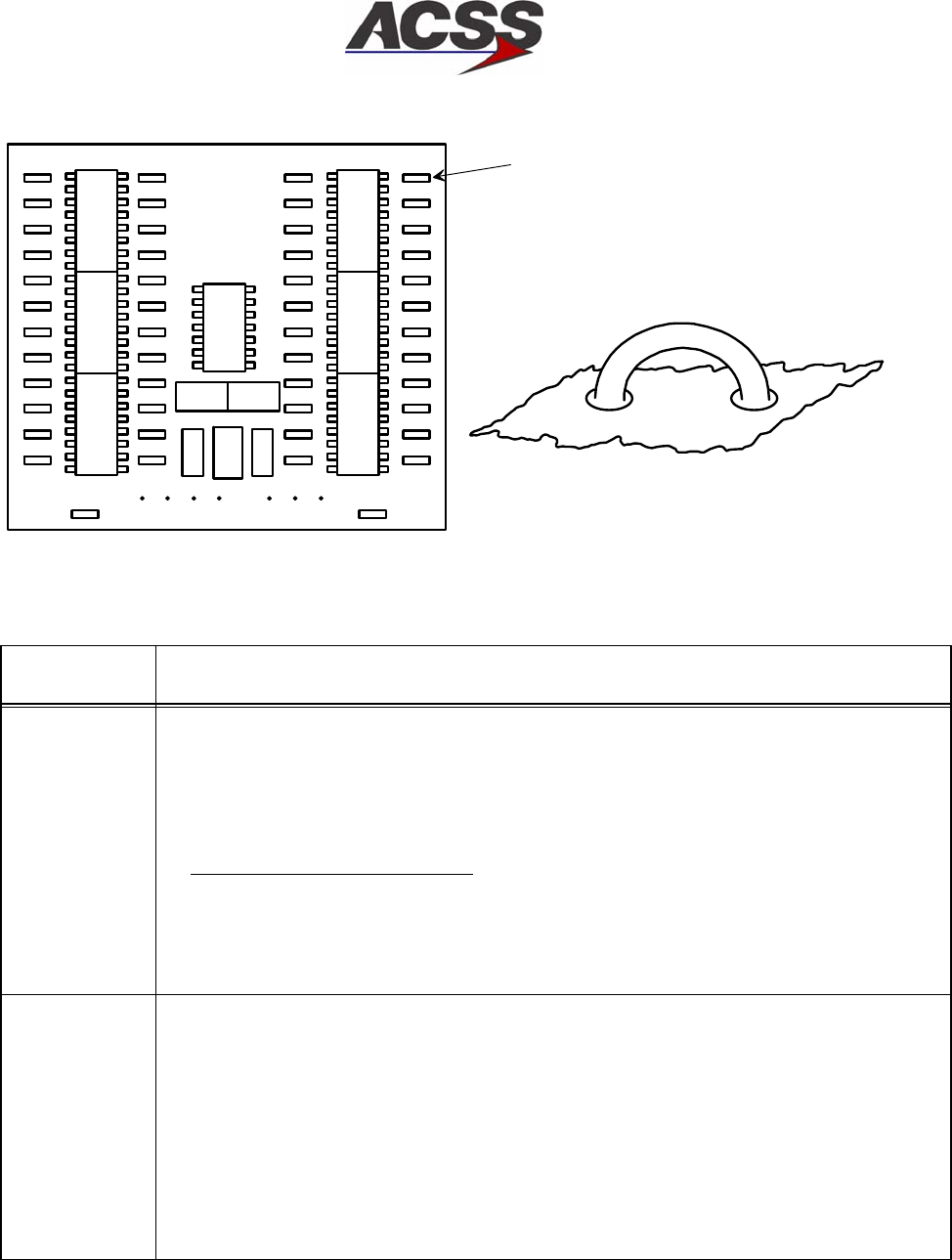
SYSTEM DESCRIPTION AND INSTALLATION MANUAL
TCAS 3000 Traffic Alert and Collision Avoidance System
34−43−23
Use or disclosure of information on this page is subject to the restrictions in the proprietary notice of this document.
Page 3−55
15 Dec 2005
W37
W38
W39
W40
W41
W42
W43
W44
W45
W46
W47
W48
W25
W26
W27
W28
W29
W30
W31
W32
W33
W34
W35
W36
W13
W14
W15
W16
W17
W18
W19
W20
W21
W22
W23
W24
W1
W2
W3
W4
W5
W6
W7
W8
W9
W10
W11
W12
W50
E8
E7
E6
E4
E3
E2
E1
W49
16
1
9
8
16
1
9
8
16
1
9
8
16
1
9
8
16
1
9
8
16
1
9
8
14
1
8
7
JUMPER WIRE (50 REQD)
SEE DETAIL A
DETAIL A
W1
AD−15341−R1@
Figure 3−12. Strap Assembly
Table 3−10. Strap Assembly Programming Instructions
Strap
Number Functional Description
W1
W2
SYSTEM (SIDE) POSITION: (B0, B1)
The System (Side) Position straps define which system position the transponder is
located at. Normal practice is to designate the captain’s or pilot’s system as Side 1, the
copilot’s system as Side 2, and the engineer’s, center, or backup system as Side 3. The
straps are defined as follows:
Strap Number
W1 W2 Definition
Gnd Gnd Side 1
Open Gnd Side 2
Gnd Open Side 3
Open Open Reserved
W3
W4
PARITY
The Parity straps are used to make sure the strap data is valid. Straps W3 and W4 are
parity bits and must be programmed as follows:
After all other straps have been programmed, count the number of Gnd (Uncut) straps in
positions W1, W2 and W5 thru W48. If the number of uncut straps is even, cut strap W3.
If the number of uncut straps is odd, cut strap W4.
NOTES:
1. To have correct parity, either jumper W3 or W4 has to be cut, but not both.
2. If parity is invalid, the transponder fails the Power−On Self−Test (POST) and
discontinues operation.

SYSTEM DESCRIPTION AND INSTALLATION MANUAL
TCAS 3000 Traffic Alert and Collision Avoidance System
34−43−23
Use or disclosure of information on this page is subject to the restrictions in the proprietary notice of this document.
Page 3−56
15 Dec 2005
Table 3−10. Strap Assembly Programming Instructions (cont)
Strap
Number Functional Description
W5 SQUAT SWITCH POLARITY
The Squat Switch Polarity strap is used to indicate the logic or signal sense of the aircraft
squat switch on ground condition. If the squat switch is closed when the aircraft is on the
ground, jumper W5 must be installed (Uncut). If the squat switch is closed when the
aircraft is airborne, jumper W5 must be Open (Cut).
W6
W7
W8
AIRCRAFT MAXIMUM TRUE AIRSPEED RANGE: (B0, B1, B2)
The Aircraft Maximum True Airspeed Range straps are used to define the aircraft’s
maximum airspeed capability. The straps are defined as follows:
Strap Number
W6 W7 W8 Definition
Gnd Gnd Gnd No Data Available
Open Gnd Gnd 75 Knots or Less
Gnd Open Gnd 76 to 150 Knots
Open Open Gnd 151 to 300 Knots
Gnd Gnd Open 301 to 600 Knots
Open Gnd Open 601 to 1200 Knots
Gnd Open Open Over 1200 Knots
Open Open Open Not Assigned
W9 thru W32
(LSB − MSB)
MODE S ADDRESS: (B0 THRU B23)
The Mode S Address is a unique 24−bit code assigned to each aircraft. Straps W9 thru
W32 are used to program this 24−bit binary number. The straps must be set according to
this binary number representation. Each binary 1 represents a Cut strap and each binary
0 represents an Uncut strap. Strap W9 represents the least significant digit of the binary
number and strap W32 represents the most significant digit of the binary number. The
initial board condition with all jumpers is a 0 address.
NOTE: An address of all 0’s or all 1’s is an illegal address, and can cause the aircraft to
be invisible to TCAS II equipped aircraft in flight. Never use an illegal address
for an installed system.
W33
W34
ALTITUDE SOURCE: (B0, B1)
The Altitude Source straps select the type of altitude information used by the transponder.
Altitude information can be generated by an encoding altimeter in the form of Gray aka
Gillham code, or by a digital Air Data Computer. The straps are defined as follows:
Strap Number
W33 W34 Definition
Gnd Gnd Gillham Gray Code Altitude Source
Open Gnd ARINC 429 Altitude Source
Gnd Open ARINC 575 Altitude Source
Open Open RSB Altitude Source
NOTE: The RSB altitude source is a valid selection only when the transponder receives
tuning information from an RCB bus.

SYSTEM DESCRIPTION AND INSTALLATION MANUAL
TCAS 3000 Traffic Alert and Collision Avoidance System
34−43−23
Use or disclosure of information on this page is subject to the restrictions in the proprietary notice of this document.
Page 3−57
15 Dec 2005
Table 3−10. Strap Assembly Programming Instructions (cont)
Strap
Number Functional Description
W35 DLP INSTALLED
The DLP Installed strap specifies whether the transponder is connected to an Airborne
Data Link Processor system. The strap is selected as follows:
Gnd = DLP is not installed
Open = DLP is installed
W36 TCAS II INSTALLED
The TCAS II Installed strap specifies whether the transponder is connected to a TCAS II
system. The strap is selected as follows:
Gnd = TCAS II is not installed
Open = TCAS II is installed
NOTE: If both TCAS II and TCAS I (strap W40) are set (Grounded), the transponder
will default to TCAS II operation. Both straps should not be cut.
W37
W38
ANTENNA CABLE INSTALLATION: (B0, B1)
The Antenna Cable Install straps are used to set the system for either a single (bottom)
antenna installation, or a diversity installation. In the diversity installation, the straps
adjust for the difference in RF propagation times through the upper and lower antenna
cables which occur because of their dissimilar lengths. The antenna cable delay is
selected as follows:
Strap Number
W37 W38 Definition
Gnd Gnd Single (bottom) Antenna Installation
Open Gnd Top > Bottom Cable Length, Differential Delay >40 nanoseconds
Gnd Open Bottom > Top Cable Length, Differential Delay >40 nanoseconds
Open Open Differential Delay is <40 nanoseconds
NOTE: The differential delay is equal to two times the length (in feet) of the difference
between the top and bottom antenna cable lengths, times the characteristic
delay (nanoseconds / feet) of the cable type in use.
W39 TCAS TA DISPLAY ENABLE
The TCAS Display Enable strap allows the TCAS display to be either tunable or fixed.
The strap is not processed by the transponder, but is used by a RMU when an RSB
tuning source is selected. The strap is not used by ARINC tuning sources. The strap
definition is as follows:
Gnd = TA Display is tunable (ON / OFF / AUTO POP−UP) modes selectable
Open = TA Display is not selectable (AUTO POP−UP mode only)
W40 TCAS I INSTALLED
The TCAS I Installed strap specifies whether the transponder is connected to a TCAS I
system. The strap is selected as follows:
Gnd = TCAS I is not installed
Open = TCAS I is installed
NOTE: If both TCAS I and TCAS II (strap W36) are set (Grounded), the transponder
will default to TCAS II operation. Both straps should not be cut.

SYSTEM DESCRIPTION AND INSTALLATION MANUAL
TCAS 3000 Traffic Alert and Collision Avoidance System
34−43−23
Use or disclosure of information on this page is subject to the restrictions in the proprietary notice of this document.
Page 3−58
15 Dec 2005
Table 3−10. Strap Assembly Programming Instructions (cont)
Strap
Number Functional Description
W41 ALTITUDE RESOLUTION
The Altitude Resolution strap allows the transponder output to the TCAS (label 203) to be
either 100 foot resolution or 1 foot resolution. The strap definition is as follows:
Gnd = 1 Foot Resolution
Open = 100 Foot Resolution
NOTE: Most ARINC altitude inputs require 1 foot resolution.
W42 thru W48 RESERVED FUNCTION
These straps are not used. The jumpers should be installed (Uncut).
W49
W50
Jumpers W49 and W50 are not part of the 48−bit serial data pulse train and are not used
on RCZ−852 Transponder installations. The jumpers should be installed (Uncut).

SYSTEM DESCRIPTION AND INSTALLATION MANUAL
TCAS 3000 Traffic Alert and Collision Avoidance System
34−43−23
Use or disclosure of information on this page is subject to the restrictions in the proprietary notice of this document.
Page 4−1
15 Dec 2005
LOADING/GRADIENT SPECIFICATIONS
1. General
This section contains the loading and gradient specifications for the input and output signals
of each component of the TCAS 3000 system.
2. Loading and Gradient Specifications
Component Table No.
TCAS 3000 Computer Unit Loading/Gradient Specifications Table 4−1
ACSS Dual Mode S Control Panel Loading/Gradient Specifications Table 4−2
ACSS ATCRBS−Mode S Control Panel Loading/Gradient Specifications Table 4−3
Gables Control Panel Loading/Gradient Specifications Table 4−4
41−Pin VSI/TRA Loading/Gradient Specifications Table 4−5
55−Pin VSI/TRA Loading/Gradient Specifications Table 4−6
Pressure Transducer Module Loading/Gradient Specifications Table 4−7
XS−950 Data Link Transponder Loading/Gradient Specifications Table 4−8
RCZ−852 Diversity Mode S Transponder Loading/Gradient Specifications Table 4−9

SYSTEM DESCRIPTION AND INSTALLATION MANUAL
TCAS 3000 Traffic Alert and Collision Avoidance System
34−43−23
Use or disclosure of information on this page is subject to the restrictions in the proprietary notice of this document.
Page 4−2
15 Dec 2005
Table 4−1. TCAS 3000 Computer Unit Loading/Gradient Specifications
Connector Pin
Designation Functional Description
TCAS Computer Unit Right Middle Plug (RMP)
RMP−1A,
RMP−1B,
RMP−1C,
RMP−1D
Reserved Discrete Outputs
RMP−1E TA Display Enable Discrete Output (NO)
This output is a ground/open type discrete used by the weather radar display to place the
radar in standby mode. A ground on this pin enables the weather radar display.
RMP−1F Corrective Aural Advisory Discrete Output (NO)
This aural advisory discrete output is a ground/open type discrete used to control external
equipment that generate tones to accompany TCAS advisories. The output is active
whenever a corrective advisory (RA that requires a corrective maneuver) is issued. The
output remains active for the duration of the synthesized voice unless it is cancelled by
the cancel discrete at RMP−3D. Only one aural advisory is active at a time. The
corrective discrete and preventative discrete at RMP−1K are mutually exclusive. The
active state is ground and the inactive state is open. This pin is reserved on the −XX001
TCAS CU.
RMP−1G,
RMP−1H
Reserved
RMP−1J Climb Inhibit No. 1 Discrete Input (NO)
This input is a ground/open type discrete used to provide information to the TCAS CU
whether to assume the aircraft cannot achieve a climb rate of 1500 feet per minute
(FPM). The climb inhibit discrete inputs are designed in pairs (No. 1 and No. 2 at
RMP−13G, or No. 3 at RBP−5J and No. 4 at RBP−5K) but can be wired as a single input
or in conjunction with other aircraft operations to achieve airframe customization of the
climb inhibit feature. The 1500 FPM climb inhibit function is assumed whenever No. 1
and No. 2 are ground or No. 3 and No. 4 are ground.
RMP−1K Preventive Aural Advisory Discrete Output (NO)
Same as RMP−1F, except this discrete is active whenever a preventative advisory (RA
that directs the flight crew to avoid certain maneuvers or maintain flight path) is issued.
RMP−2A Traffic Aural Advisory Discrete Output (NO)
Same as RMP−1F, except this discrete is active during a traffic advisory when information
is being given to the flight crew regarding other aircraft in the immediate vicinity. No
suggested maneuver is issued. This output is inhibited if either the corrective or
preventative output is active.
RMP−2B,
RMP−2C
Reserved
RMP−2D Advisory/Announce Common
This is the return line for the aural and visual advisory discrete outputs.

SYSTEM DESCRIPTION AND INSTALLATION MANUAL
TCAS 3000 Traffic Alert and Collision Avoidance System
34−43−23
Use or disclosure of information on this page is subject to the restrictions in the proprietary notice of this document.
Page 4−3
15 Dec 2005
Table 4−1. TCAS 3000 Computer Unit Loading/Gradient Specifications (cont)
Connector Pin
Designation Functional Description
RMP−2E Spare Pin
RMP−2F, 2G 8−Ohm Audio Output: (RMP−2F [HI], RMP−2G [LO])
This is a synthesized voice output supplied by the TCAS computer unit. Its level is
programmable up to 4 Watts into an 8−ohm speaker. All aural traffic and resolution
advisories are announced over this output. See RBP−7A for audio level programming.
RMP−2H, 2J Radio Altimeter No. 1 ARINC 552/Analog Input: (RMP−2H [HI], RMP−2J [LO])
Normal aircraft configurations include either two digital or two analog radio altimeter
sources. The TCAS computer unit attempts to establish which type is present in order to
obtain data from one of the two available sources. TCAS first checks the radio altimeter
No. 1 valid flag at RMP−2K. If No. 1 is not valid then No. 2 valid is checked at RBP−3C.
If neither are valid then TCAS checks digital source No. 1 for valid data on the ARINC
429 bus at RMP−13H and RMP−13J. If none of the above are valid then the TCAS
checks the digital source No. 2 for valid data on the ARINC 429 bus at RBP−3D and
RBP−3E. This process is repeated until a valid flag or data is detected.
Until a valid source is found, the TCAS computer unit inhibits all surveillance, CAS, and
TA/RA display functions, records failures in maintenance memory, and sets the TCAS
system status discrete output at RMP−13K to invalid. The TCAS computer unit uses
radio altitude to inhibit advisories and aural annunciation when in close proximity to the
ground. This analog input No. 1, as well as analog input No. 2, can accept data as a dc
voltage from several types of radio altimeters. The type of radio altimeter is selected
using the program pins RMP−12B and RMP−12H thru RMP−12K.
RMP−2K Radio Altimeter No. 1 Valid Input (PO)
See RMP−2H. A valid condition is greater than 18.5 V dc. An invalid is open circuit.
RMP−3A Corrective Visual Advisory Discrete Output (NO)
The visual advisory discrete outputs are ground/open type discretes used to operate the
annunciator lights on the displays. This output is activated whenever a corrective aural
advisory is issued. The output remains active for the duration of the advisory unless
cancelled by the cancel discrete at RMP−3D. Only one visual advisory is active at a time.
The active state is ground and the inactive state is open.
RMP−3B Preventive Visual Advisory Discrete Output (NO)
Same as RMP−3A, except this discrete is activated whenever a preventative aural
advisory is issued.
RMP−3C Traffic Visual Advisory Discrete Output (NO)
Same as RMP−3A, except this discrete is active during a traffic advisory.
RMP−3D Cancel Discrete Input (NO)
This input discrete provides a means of canceling aural and visual alerts. It should be
connected to a cancel button (momentary ground type), if used. Groundprox/Windshear
has priority over the cancel button. Open is the inactive state and a momentary ground
(less than 50 ohms) produces the active state, canceling any active aural or visual alert.

SYSTEM DESCRIPTION AND INSTALLATION MANUAL
TCAS 3000 Traffic Alert and Collision Avoidance System
34−43−23
Use or disclosure of information on this page is subject to the restrictions in the proprietary notice of this document.
Page 4−4
15 Dec 2005
Table 4−1. TCAS 3000 Computer Unit Loading/Gradient Specifications (cont)
Connector Pin
Designation Functional Description
RMP−3E Spare Pin
RMP−3F, 3G 600−Ohm Audio Output: [RMP−3F (HI), RMP−3G (LO)]
This is a synthesized voice output supplied by the TCAS computer unit. Its level is
programmable up to 80 milliwatts into a 600−ohm audio distribution system. All aural
traffic and resolution advisories are annunciated over this output. See RBP−7A for audio
level programming.
RMP−3H Spare Pins
RMP−3J,
RMP−3K
Reserved for future use.
RMP−4A Reserved for future use.
RMP−4B Reserved for future use.
RMP−4C Reserved for future use.
RMP−4D Shield Ground
Reserved for future use.
RMP−4E Reserved for future use.
RMP−4F Reserved for future use.
RMP−4G Reserved for future use.
RMP−4H Reserved for future use.
RMP−4J Reserved for future use.
RMP−4K Attitude Valid Discrete Input
Reserved for future use.

SYSTEM DESCRIPTION AND INSTALLATION MANUAL
TCAS 3000 Traffic Alert and Collision Avoidance System
34−43−23
Use or disclosure of information on this page is subject to the restrictions in the proprietary notice of this document.
Page 4−5
15 Dec 2005
Table 4−1. TCAS 3000 Computer Unit Loading/Gradient Specifications (cont)
Connector Pin
Designation Functional Description
RMP−5A Reserved for future use.
RMP−5B Reserved for future use.
RMP−5C Reserved for future use.
RMP−5D Reserved for future use.
RMP−5E ADS−B Program Input
Intruder File Enable
RMP−5F ADS−B Program Input
GP Bus enable
RMP−5G ADS−B Program Input
Future Spare
RMP−5H Reserved for future use.
RMP−5J Reserved for future use.
RMP−5K Air Ground Discrete Input (NO): (Weight−On−Wheels)
This discrete input to the TCAS computer unit indicates the status of the Air/Ground or
Weight−On−Wheels (WOW) switch. TCAS filters this input to make sure it remains in a
steady state a minimum of 4 seconds before an Air/Ground transition is recorded. An
open indicates the aircraft is airborne and a ground indicates the aircraft is on the ground.
Inputs should be diode isolated from each other.
RMP−6A, 6B ARINC 429 Performance Limit Input: [RMP−6A (A), RMP−6B (B)]
This input is provided for future applications to receive climb rate performance limit
information from an external device such as a Flight Management Computer.
RMP−6C Magnetic Heading Valid Discrete Input
Reserved for future use.
RMP−6D Performance Limit Discrete Input (NO)
This input provides the TCAS computer unit with an input from the Flight Management
Computer (or equivalent) which indicates when the aircraft cannot achieve a 1500 FPM
climb rate. When this input is ground, the climb rate is not limited and no action is
needed by the TCAS computer unit. When this input is open, the climb rate is limited
when the aircraft is above the value set by the altitude limit program pins (RMP−6E thru
RMP−6J).

SYSTEM DESCRIPTION AND INSTALLATION MANUAL
TCAS 3000 Traffic Alert and Collision Avoidance System
34−43−23
Use or disclosure of information on this page is subject to the restrictions in the proprietary notice of this document.
Page 4−6
15 Dec 2005
Table 4−1. TCAS 3000 Computer Unit Loading/Gradient Specifications (cont)
Connector Pin
Designation Functional Description
RMP−6E 2000 FT Altitude Limit Program Pin (NO)
This pin, along with pins RMP−6F thru RMP−6J, select the “can’t climb” altitude in
2,000−foot increments up to 62,000 feet. This is the altitude the aircraft is not able to
achieve a 0.25 G vertical acceleration to a 1500 FPM climb rate for an altitude gain of 750
feet above a certain altitude under all circumstances. The “can’t climb” altitude is
selected by connecting jumper wires from altitude limit program pins to the program
common pin (RMP−6K).
RMP−6F 4000 FT Altitude Limit Program Pin (NO)
See RMP−6E.
RMP−6G 8000 FT Altitude Limit Program Pin (NO)
See RMP−6E.
RMP−6H 16000 FT Altitude Limit Program Pin (NO)
See RMP−6E.
RMP−6J 32000 FT Altitude Limit Program Pin (NO)
See RMP−6E.
RMP−6K Program Common
See RMP−6E.
RMP−7A, 7B ARINC 429 Magnetic Heading/Attitude Input: [RMP−7A (A), RMP−7B (B)]
Reserved for future use
RMP−7C, 7D ARINC 429 TA/RA Display No. 1 Output: [RMP−7C (A), RMP−7D (B)]
This is one of two ARINC 429 high speed bus outputs that supplies data to the TA/RA
display such as a VSI/TRA or EFIS. The other output (TA/RA Display No. 2) is at
RMP−7G and −7H. The TA/RA Display No. 1 outputs are also connected to the front
(PDL) connector, which is used to supply display information to maintenance displays.
See J1−33 and J1−34.
RMP−7E TA/RA Display No. 1 Status Discrete Input (NO)
Two display status discrete inputs are provided by the TCAS computer unit at RMP−7E
(TA/RA Display No. 1) and RMP−7J (TA/RA Display No. 2). A ground on either of these
inputs is interpreted by TCAS to mean the display associated with that input is operating
normally and is capable of displaying the TA/RA information, and that its data bus is
active. An open indicates the inability of the display to present advisories or indicates its
data bus is inactive.
RMP−7F Spare Pin
RMP−7G, 7H ARINC 429 TA/RA Display No. 2 Output: [RMP−7G (A), RMP−7H (B)]
See RMP−7C and −7D.
RMP−7J TA/RA Display No. 2 Status Discrete Input (NO)
See RMP−7E.
RMP−7K Spare Pin

SYSTEM DESCRIPTION AND INSTALLATION MANUAL
TCAS 3000 Traffic Alert and Collision Avoidance System
34−43−23
Use or disclosure of information on this page is subject to the restrictions in the proprietary notice of this document.
Page 4−7
15 Dec 2005
Table 4−1. TCAS 3000 Computer Unit Loading/Gradient Specifications (cont)
Connector Pin
Designation Functional Description
RMP−8A, 8B ARINC 429 Data Loader Input: [RMP−8A (A), RMP−8B (B)]
These pins are used when the TCAS computer unit is communicating with an ARINC 603
or 615 airborne data loader (ADL) through the rear ARINC 600 connector. The data
loader programs the program memory in the TCAS computer unit per the data loader
function specified. The ADL and portable data loader (PDL) ARINC 429 inputs have
separate receiver busses to allow for simultaneous connection of the ADL and PDL.
These pins are also connected to the front (PDL) connector on the front of the unit. See
J1−1 and J1−2.
RMP−8C,8D TA/RA Display Control ARINC 429 Input #1: [RMP−8C (A), RMP−8D (B)]
RMP−8E, 8F ARINC 429 Bus Input: [RMP−8E (A), RMP−8F (B)]
Reserved for future use.
RMP−8G, 8H TA/RA Display Control ARINC 429 Input #2: [RMP−8G (A), RMP−8H (B)]
RMP−8J, 8K ARINC 429 ADS−B No. 2 Input: [RMP−8J (A), RMP−8K (B)]
Reserved for future use.
RMP−9A, 9B ARINC 429 Data Loader Output: [RMP−9A (A), RMP−9B (B)]
These pins are used when the TCAS computer unit is communicating with an ARINC 603
or 615 airborne data loader (ADL) through the rear ARINC 600 connector. This
connection is used to transmit data to the ADL during data loading operations.
These pins are also connected to the front (PDL) connector on the front of the unit. See
J1−8 and J1−9.
RMP−9C, 9D ARINC 429 ADS−B No. 1 Output: [RMP−9C (A), RMP−9D (B)]
Reserved for future use.
RMP−9E, 9F ARINC 429 Bus Output: [RMP−9E (A), RMP−9F (B)]
Reserved for future use.
RMP−9G, 9H ARINC 429 Bus Output: [RMP−9G (A), RMP−9H (B)]
Reserved for future use.
RMP−9J, 9K ARINC 429 ADS−B No. 2 Output: [RMP−9J (A), RMP−9K (B)]
Reserved for future use.

SYSTEM DESCRIPTION AND INSTALLATION MANUAL
TCAS 3000 Traffic Alert and Collision Avoidance System
34−43−23
Use or disclosure of information on this page is subject to the restrictions in the proprietary notice of this document.
Page 4−8
15 Dec 2005
Table 4−1. TCAS 3000 Computer Unit Loading/Gradient Specifications (cont)
Connector Pin
Designation Functional Description
RMP−10A
RMP−10B
RMP−10C
ADS−B Program Inputs
Reserved for future use.
RMP−10D Single Mode S Transponder Input
This pin must be grounded when system is configured with a single Mode S transponder.
Failure to ground this program pin in a single Mode S installation will result in XPNDR bus
faults displayed on fault data LEDs.
RMP−10E
Thru
RMP−10J
Reserved Program Inputs
Reserved for future use.
RMP−10K ADS−B Surveillance Program Input
This program pin enables passive surveillance using ADS−B DF−17 extended squitters.
A ground on this pin enables ADS−B surveillance and an open disables ADS−B
surveillance.
RMP−11A Reserved Program Input
Reserved for future use.
RMP−11B Traffic Display of Flight ID Program Input
This program pin allows traffic display of flight identification information from a
transponder to be output on the TA/TA displays. A ground on this pin enables this
function and an open disables the function.
RMP−11C Male Voice Program Input
This program input is intended to allow audio annunciation to be selectable for either male
or female genders. A ground on this pin selects the male voice and an open selects the
female voice.
RMP−11D Flight Data Recorder ARINC 429 and Extended Maintenance Log Program Input
This program pin is used to specify whether the ARINC 429 Flight Data Recorder (FDR)
is to be used. An open on this pin means that the FDR is not utilized. A ground indicates
that flight data is output as high−speed ARINC 429 data on RA Display No. 1 and No. 2
busses. While the FDR is enabled, normal low−speed RA display bus operation is not
available. A ground also enables RA/TA events recording in memory.
RMP−11E
Thru
RMP−11K
Reserved Data Bus Inputs
Reserved for future use.
RMP−12A Reserved Program Input
Reserved for future use.

SYSTEM DESCRIPTION AND INSTALLATION MANUAL
TCAS 3000 Traffic Alert and Collision Avoidance System
34−43−23
Use or disclosure of information on this page is subject to the restrictions in the proprietary notice of this document.
Page 4−9
15 Dec 2005
Table 4−1. TCAS 3000 Computer Unit Loading/Gradient Specifications (cont)
Connector Pin
Designation Functional Description
RMP−12B Radio Altimeter Type Select Program Input No. 4 (NO)
The TCAS computer unit uses radio altitude to inhibit advisories and aural annunciation
when in close proximity to the ground. This analog input No. 1, as well as analog input
No. 2 can accept data as a dc voltage from several types of radio altimeters. Program
pin RMP−12B is used, along with program pins RMP−12H, −12J, and −12K, to identify the
type of analog radio altimeter installed.
ARINC 552, Collins BCA, and metric type radio altimeters can be selected. In addition
radio altimeter inputs can be selected which include AHV−6, NR−AS−10A, LPIA, and
APN−232 CARA. The program pin inputs use ground/open logic levels. All unassigned
program pin combinations are invalid and should not be selected. Pin RMP−6K can be
used to supply a ground.
Program Pin
RMP−12K RMP−12J RMP−12H RMP−12B Altimeter Type
Open Open Open Open ARINC 552/552A
Open Open Open Ground Collins BCA
Open Open Ground Open Metric Altimeter No. 1
Open Open Ground Ground Unassigned
Open Ground Open Open Metric Altimeter No. 2
Open Ground Open Ground Unassigned
Open Ground Ground Open Metric Altimeter No. 3
Open Ground Ground Ground Unassigned
Ground Open Open Open Metric Altimeter No. 4
Ground Open Open Ground Unassigned
Ground Open Ground Open Military AHV6 (Linear)
Ground Open Ground Ground Military AHV6 (Log)
Ground Ground Open Open Military NR−AS−10A (Alternate)
Ground Ground Open Ground Military APN−232 CARA
Ground Ground Ground Open Military LPIA
Ground Ground Ground Ground Military NR−AS−10A (Curve Fit)
Each of the military radio altimeter types provide two outputs that are connected to the
TCAS computer unit input pins. The two altimeter outputs are the Analog Data Output
and Analog Data Reliability Signal. The Data Reliability Signal is connected to RMP−2K
for source No. 1 and RBP−3C for source No. 2, except for altimeter type LPIA. For radio
altimeter type LPIA, the Analog Data Output must be connected to RMP−2H (HI) and
RMP−2J (LO), the Analog Data Reliability Signal must be connected to RBP−3A (HI) and
RBP−3B (LO), and the inputs RMP−2K and RMP−3C are set high (greater than 18.5 V).
The metric radio altimeters are defined as follows:
Metric
Altimeter Definition
No. 1 Metric unit− 1000 meter range, 25 mV/M scaling
No. 2 Metric unit− 1000 meter range, 20 mV/M scaling
No. 3 Metric unit− 1500 meter range, 20 mV/M scaling
No. 4 Metric unit− 750 meter range, 50 mV/M scaling

SYSTEM DESCRIPTION AND INSTALLATION MANUAL
TCAS 3000 Traffic Alert and Collision Avoidance System
34−43−23
Use or disclosure of information on this page is subject to the restrictions in the proprietary notice of this document.
Page 4−10
15 Dec 2005
Table 4−1. TCAS 3000 Computer Unit Loading/Gradient Specifications (cont)
Connector Pin
Designation Functional Description
RMP−12C RA/TA Block Transfer Program Input (NO)
This program input determines the type of block transfer that is made from the TCAS
computer unit to the TA/RA displays. If this pin is grounded, the TCAS computer unit
transmits in ACSS BCA EFIS format. If the TCAS computer unit senses an open at this
pin, it transmits in ARINC 735 format.
RMP−12D Reserved Program Input
RMP−12E Reserved Program Input
RMP−12F Spare Pin
RMP−12G Option Parity Program Input
The TCAS computer unit uses nine discrete program input pins to determine which
options have been selected by the installer. Eight of these pins are used to determine
option selections. The ninth pin (RMP−12G) is used to determine parity for the eight
option selection pins (RMP−10G, −10H, −10J, −10K, −11A, −11B, −11C, and −11D). To
determine parity, count the number of option pins that are grounded. If the number of
pins that are grounded is an odd number (1, 3, 5, 7), ground pin RMP−12G. If the
number of grounded pins in the option group is an even number (0, 2, 4, 6, 8), leave pin
RMP−12G open.
RMP−12H Analog Radio Altimeter Type Select Program Input No. 3 (NO)
See RMP−12B.
RMP−12J Analog Radio Altimeter Type Select Program Input No. 2 (NO)
See RMP−12B.
RMP−12K Analog Radio Altimeter Type Select Program Input No. 1 (NO)
See RMP−12B.
RMP−13A, 13B RA Display No. 1/ARINC 429 Data Recorder Output: [RMP−13A (A), RMP−13B (B)]
These ARINC 429 outputs are configured to output either RA information or for use as an
ARINC 429 data recorder function. The output is configured by program pin RMP−11D.
When RMP−11D is open (standard configuration), the bus is configured for low−speed
ARINC 429 operation and RA information is output according to the format specified for
the RA display bus in ARINC 735. When RMP−11D is grounded, the bus is configured for
high−speed ARINC 429 operation and the output supplies TA and RA information to a 429
data recorder.
RMP−13C, 13D RA Display No. 2/ARINC 429 Data Recorder Output: [RMP−13C (A), RMP−13D (B)]
See RMP−13A.
RMP−13E RA Display No. 2 Status Discrete Input (NO)
This input provides the functional status of RA Display No. 2. A ground on this pin
indicates a valid display. If this discrete is not used by the RA Display, connect to aircraft
ground to prevent RA DISPLAY No. 2 fail message during self−test.

SYSTEM DESCRIPTION AND INSTALLATION MANUAL
TCAS 3000 Traffic Alert and Collision Avoidance System
34−43−23
Use or disclosure of information on this page is subject to the restrictions in the proprietary notice of this document.
Page 4−11
15 Dec 2005
Table 4−1. TCAS 3000 Computer Unit Loading/Gradient Specifications (cont)
Connector Pin
Designation Functional Description
RMP−13F Landing Gear Discrete Input (NO)
The TCAS computer unit monitors this discrete that indicates the landing gear position.
An open indicates the gear is retracted (gear is up) and a ground indicates the gear is
extended (gear is down).
RMP−13G Climb Inhibit No. 2 Discrete Input (NO)
See RMP−1J.
RMP−13H, 13J Radio Altimeter No. 1 Input: [RMP−13H (A), RMP−13J (B)]
This input is provided for ARINC 429 altitude inputs from an ARINC 707 digital radio
altimeter. Radio altitude data is used for computation of sensitivity level, inhibit descend
advisories, and inhibit aural annunciation when in close proximity to the ground. Also see
RMP−2H.
RMP−13K TCAS System Valid Discrete Output (NO)
This discrete output indicates the health status of the TCAS computer unit to other
avionics systems that monitor TCAS system status. This output is used in retrofit
installations where instrumentation needs to monitor TCAS status. A ground at this pin
indicates normal TCAS operation. An open indicates a TCAS fault.
RMP−14A, 14B ARINC 429 TX Coordination Bus No. 2 Output: [RMP−14A (A), RMP−14B (B)]
This differential pair output is a high speed ARINC 429 bus (100K bits/second nominal),
that transmits data from the TCAS computer unit to the No. 2 Mode S Transponder.
The labels on this bus are as follows: 273, 274, 275.
RMP−14C RA Display No. 1 Status Discrete Input (NO)
This input provides the functional status of RA Display No. 1. A ground on this pin
indicates a valid display. If this discrete is not used by the RA display, connect to aircraft
ground to prevent RA DISPLAY No. 1 fail message during self−test.
RMP−14D, 14E Selected Altitude701/720 ARINC 429 Bus Input
Reserved for future use.
RMP−14F, 14G ARINC 429 XT Coordination No. 1 Input: [RMP−14F (A), RMP−14G (B)]
This differential pair input is a high speed ARINC 429 bus (100K bits/second nominal),
that receives data from the No. 1 Mode S Transponder.
The labels on this bus are as follows: 013, 015, 016, 203, 271, 272, 273, 274, 275, 276,
277, 350.
RMP−14H, 14J ARINC 429 XT Coordination No. 2 Input: [RMP−14H (A), RMP−14J (B)]
This differential pair input is a high speed ARINC 429 bus (100K bits/second nominal),
that receives data from the No. 2 Mode S Transponder.
The labels on this bus are as follows: 013, 015, 016, 203, 271, 272, 273, 274, 275, 276,
277, 350.
RMP−14K Spare Pin

SYSTEM DESCRIPTION AND INSTALLATION MANUAL
TCAS 3000 Traffic Alert and Collision Avoidance System
34−43−23
Use or disclosure of information on this page is subject to the restrictions in the proprietary notice of this document.
Page 4−12
15 Dec 2005
Table 4−1. TCAS 3000 Computer Unit Loading/Gradient Specifications (cont)
Connector Pin
Designation Functional Description
RMP−15A
thru
RMP−H
Reserved for future use.
RMP−15J, 15K ARINC 429 TX Coordination No. 1 Output: [RMP−15J (A), RMP−15K (B)]
This differential pair output is a high speed ARINC 429 bus (100K bits/second nominal),
that transmits data from the TCAS computer unit to the No. 1 Mode S Transponder.
The labels on this bus are as follows: 273, 274, 275.
TCAS Computer Unit Right Bottom Plug (RBP)
RBP−1A
Thru
RBP−1G
Reserved for future use.
RBP−1H RA Data Word 270 Bit 18 Discrete Output
This discrete output provides RA information to the ARINC 573 flight recorder. The
output goes to the “ground” state each time its associated bit within the advisory field of
the RA output words changes from a “zero” condition to a “one” condition. The output
remains in the “ground” state for as long as the associated RA bit remains non−zero.
This output is read by the flight recorder as either a series or shunt output.
RBP−1J RA Data Word 270 Bit 19 Discrete Output
See RBP−1H.
RBP−1K RA Data Word 270 Bit 20 Discrete Output
See RBP−1H.
RBP−2A
Thru
RBP−2G
Spare Pins
RBP−2H RA Data Word 270 Bit 21 Discrete Output
See RBP−1H.
RBP−2J RA Data Word 270 Bit 22 Discrete Output
See RBP−1H.
RBP−2K RA Data Word 270 Bit 23 Discrete Output
See RBP−1H.
RBP−3A, 3B Radio Altimeter No. 2 ARINC 552/Analog Input: [RBP−3A (HI), RBP−3B (LO)]
See RMP−2H and −2J.
RBP−3C Radio Altimeter No. 2 Valid Discrete Input (PO)
See RMP−2H. Valid condition is greater than 18.5 V dc. Invalid is open.
RBP−3D, 3E Radio Altimeter No. 2 Input: [RBP−3D (A), RBP−3E (B)]
See RMP−13H. Also see RMP−2H.

SYSTEM DESCRIPTION AND INSTALLATION MANUAL
TCAS 3000 Traffic Alert and Collision Avoidance System
34−43−23
Use or disclosure of information on this page is subject to the restrictions in the proprietary notice of this document.
Page 4−13
15 Dec 2005
Table 4−1. TCAS 3000 Computer Unit Loading/Gradient Specifications (cont)
Connector Pin
Designation Functional Description
RBP−3F,
RBP−3G
Spare Pins
RBP−3H RA Data Word 270 Bit 24 Discrete Output
See RBP−1H.
RBP−3J RA Data Word 270 Bit 25 Discrete Output
See RBP−1H.
RBP−3K RA Data Word 270 Bit 26 Discrete Output
See RBP−1H.
RBP−4A
Thru
RBP−4F
Reserved Discrete Inputs
Reserved for future use.
RBP−4G RA Display Test Inhibit Program Pin
This program pin is used to determine if RA discrete monitoring will be inhibited during
self−test. If this pin is connected to program common (ground), RA discrete self−test
monitoring is inhibited. An open on this pin indicates RA discretes monitoring during
self−test.
RBP−4H RA Data Word 270 Bit 27 Discrete Output
See RBP−1H.
RBP−4J RA Data Word 270 Bit 28 Discrete Output
See RBP−1H.
RBP−4K RA Data Word 270 Bit 29 Discrete Output
See RBP−1H.

SYSTEM DESCRIPTION AND INSTALLATION MANUAL
TCAS 3000 Traffic Alert and Collision Avoidance System
34−43−23
Use or disclosure of information on this page is subject to the restrictions in the proprietary notice of this document.
Page 4−14
15 Dec 2005
Table 4−1. TCAS 3000 Computer Unit Loading/Gradient Specifications (cont)
Connector Pin
Designation Functional Description
RBP−5A Advisory Inhibit Discrete Input No. 1 (NO)
Four discrete inputs at RBP−5A, −5B, −5C, and −5D provide the capability for the TCAS
computer unit to defer all advisory (TA), aural alert and visual alert outputs until another,
higher priority announcement or alert is completed. An open at all four of these discrete
inputs indicates normal advisory/alert operation. These discrete inputs become active by
connection to program common (ground) at RBP−7K. No new TA information can be
placed on the RA or RA/TA busses during a period of Advisory Inhibit. If an advisory
condition, which occurred during a period of Advisory Inhibit, remains when the TCAS
computer unit returns to normal operation, it is annunciated. The Advisory Inhibit inputs
and their effect on the advisory/alert priority system are as follows:
Discrete No. Pin No. Mode Priority
1 RBP−5A Forced Standby 1
2 RBP−5B Force TA Only (no voice/tone) 2
3 RBP−5C Force TA Only (no voice/tone) 2
4 RBP−5D Force TA Only (no voice/tone) 2
Discrete No. 1 (RBP−5A) has priority over No. 2 (RBP−5B), No. 3 (RBP−5C) and No. 4
(RBP−5D). Discrete No. 1 forces TCAS into STANDBY mode. Discretes No. 2, No. 3,
and No. 4 force TCAS into TA mode with no voice or tone annunciations.
RBP−5B Advisory Inhibit Discrete Input No. 2 (NO)
See RBP−5A.
RBP−5C Advisory Inhibit Discrete Input No. 3 (NO)
See RBP−5A.
RBP−5D Advisory Inhibit Discrete Input No. 4 (NO)
See RBP−5A.
RBP−5E Increase Climb Inhibit Discrete Input No. 1 (NO)
This input is a ground/open type discrete used to provide information to the TCAS CU
whether to assume that the aircraft cannot achieve a climb rate of 2500 feet per minute
(FPM). The climb inhibit discrete inputs are designed in pairs (No. 1 and No. 2 at
RBP−5F, or No. 3 at RBP−5G and No. 4 at RBP−5H) but can be wired as a single input
or in conjunction with other aircraft operations to achieve airframe customization of the
climb inhibit feature. The 2500 FPM climb inhibit function is assumed whenever No. 1
and No. 2 are ground or No. 3 and No. 4 are ground.
RBP−5F Increase Climb Inhibit Discrete Input No. 2 (NO)
See RBP−5E.
RBP−5G Increase Climb Inhibit Discrete Input No. 3 (NO)
See RBP−5E.
RBP−5H Increase Climb Inhibit Discrete Input No. 4 (NO)
See RBP−5E.
RBP−5J Climb Inhibit Discrete Input No. 3 (NO)
See RMP−1J.

SYSTEM DESCRIPTION AND INSTALLATION MANUAL
TCAS 3000 Traffic Alert and Collision Avoidance System
34−43−23
Use or disclosure of information on this page is subject to the restrictions in the proprietary notice of this document.
Page 4−15
15 Dec 2005
Table 4−1. TCAS 3000 Computer Unit Loading/Gradient Specifications (cont)
Connector Pin
Designation Functional Description
RBP−5K Climb Inhibit Discrete Input No. 4 (NO)
See RMP−1J.
RBP−6A Airborne Data Loader Link A Discrete Input
This discrete input, along with Data Loader Discrete Inputs No. 2, 3, and 4 (pins RBP−6B,
RBP−6C, and RBP−6D, respectively), is a ground/open type discrete that specifies what
type of data loader (ARINC 603 or ARINC 615) is attached. The TCAS computer unit has
separate receiver busses and separate data loader enable discrete inputs to support
simultaneous connections to an ADL and PDL. A ground on pin RBP−6A indicates that
an airborne data loader is connected to the rear connector of the TCAS computer unit. A
ground on pin J1−18, PDL Link A Discrete Input, indicates that a portable data loader is
connected to the front connector of the TCAS computer unit. The data loader discrete
inputs at RBP−6B, RBP−6C, and RBP−6D are also connected to the data loader discrete
inputs on the front connector (pins J1−51, J1−52, and J1−53, respectively). Listed below
is an active discrete (selected) indicated by a ground and an inactive discrete (not
selected) indicated by an open.
J1−51/ J1−52/ J1−53/
RBP−6A J1−18 RBP−6B RBP−6C RBP−6D Function
Ground Open Ground Open Open ARINC 615 ADL
Ground Open Open Ground Open ARINC 603 ADL
Open Ground Ground Open Open ARINC 615 PDL
Open Ground Open Ground Open ARINC 603 PDL
− − − − − − − −Ground SW Part Number is output
RBP−6B Data Loader Discrete Input No. 2
See RBP−6A.
RBP−6C Data Loader Discrete Input No. 3
See RBP−6A.
RBP−6D Data Loader Discrete Input No. 4
See RBP−6A.
RBP−6E, 6F ARINC 429 CFDS Output: [RBP−6E (A), RBP−6F (B)]
This differential pair output is a low speed ARINC 429 bus (12.5K bits/second nominal),
that transmits data to an onboard maintenance computer or a central fault display system.
RBP−6G, 6H ARINC 429 CFDS Input: [RBP−6G (A), RBP−6H (B)]
This differential pair input is a low speed ARINC 429 bus (12.5K bits/second nominal),
that receives data from an onboard maintenance computer or a central fault display
system.
RBP−6J Single Mode S Program Pin
Ground this pin when the computer is connected to a single mode S transponder.
RBP−6K Single Radio Altimeter Program Pin
Ground this pin when the computer is connected to a single radio altimeter.

SYSTEM DESCRIPTION AND INSTALLATION MANUAL
TCAS 3000 Traffic Alert and Collision Avoidance System
34−43−23
Use or disclosure of information on this page is subject to the restrictions in the proprietary notice of this document.
Page 4−16
15 Dec 2005
Table 4−1. TCAS 3000 Computer Unit Loading/Gradient Specifications (cont)
Connector Pin
Designation Functional Description
RBP−7A Audio Level Program Pin No. 1 (NO)
Two synthesized voice outputs with programmable output levels are provided by the
TCAS computer unit. The output at RMP−2F and −2G supply high level (up to 4 Watts)
audio signals to an 8 ohm speaker. The second output at RMP−3F and −3G supply low
level (up to 80 milliwatts) audio signals to a 600 ohm audio distribution system. All aural
traffic and resolution advisories can be annunciated over these outputs unless cancelled
by a Cancel Discrete (RMP−3D).
Listed below are the audio level program pin configurations and the resulting output
levels:
Program Pin
RBP−7A RBP−7B RBP−7C Low Level Output High Level Output
(MSB) (LSB) dBm mW dBm W
Open Open Open 16 40 6 4
Open Open Ground 13 20 3 2
Open Ground Open 10 10 0 1
Open Ground Ground 7 5 −3 0.5
Ground Open Open 4 2.5 −6 0.25
Ground Open Ground 1 1.25 −9 0.125
Ground Ground Open −2 0.625 −12 0.0625
Ground Ground Ground 19 80 Not Used Not Used
RBP−7B Audio Level Program Pin No. 2 (NO)
See RBP−7A.
RBP−7C Audio Level Program Pin No. 3 (NO)
See RBP−7A.
RBP−7D Audio Tone Enable Program Pin (NO)
If this programming pin is connected to program common, (RBP−7K), all voice
announcements are delayed by one second and are preceded by a tone. If pin is left
open, no delays or tones occur.
RBP−7E Ground Display Mode Program Pin (NO)
The TCAS computer unit monitors this programming pin to select the TCAS ground
display mode while the aircraft is on the ground. If the aircraft is on the ground and this
pin is connected to program common (RBP−7K), TCAS goes into standby mode. If this
pin is left open and the aircraft is on the ground, TCAS displays traffic only. Aural and
voice annunciations are inhibited while the aircraft is on the ground.
NOTE: TCAS does not display any traffic that it locates on the ground. TCAS aircraft
has WOW and intruder aircraft reports the same altitude or a lower altitude.
RBP−7F Display All Traffic Program Pin (NO)
The TCAS computer unit monitors this program pin to select either the all traffic display
mode or the TA/RA only mode. If this pin is open, all traffic is displayed. If this pin is
connected to program common (RBP−7K), the TCAS displays only TA/RA type intruders.

SYSTEM DESCRIPTION AND INSTALLATION MANUAL
TCAS 3000 Traffic Alert and Collision Avoidance System
34−43−23
Use or disclosure of information on this page is subject to the restrictions in the proprietary notice of this document.
Page 4−17
15 Dec 2005
Table 4−1. TCAS 3000 Computer Unit Loading/Gradient Specifications (cont)
Connector Pin
Designation Functional Description
RBP−7G Cable Delay Signal Program Pin (NO)
The cable delay program pins (RBP−7G, RBP−7H, and RBP−7J) convey to the TCAS
computer unit the amount of delay differential between the top and bottom antenna
cables. Pin RBP−7G determines whether a time delay is added to the top or bottom. If
this pin is open, the time delay is added to the top. If this pin is ground (connected to
program pin RBP−7K), the time delay is added to the bottom. The cable delay logic is
given below. Program common for the cable delay program pins is RBP−7K.
RBP−7H RBP−7J Differential
(MSB) (LSB) Delay Adjustment
Open Open 0−50 nsec No Change
Open Ground 51−150 nsec Add 100 nsec delay
Ground Open 151−250 nsec Add 200 nsec delay
Ground Ground 251−350 nsec Add 300 nsec delay
RBP−7H Cable Delay MSB Program (NO)
See RBP−7G.
RBP−7J Cable Delay LSB Program Pin (NO)
See RBP−7G.
RBP−7K Program Common
This is the ground source for use with program pins.
RBP−8A
Thru
RBP−8D
Reserved Program Pins
RBP−8E Self−Test Test Inhibit Program Pin (NO)
This program pin determines if self−test will be inhibited while airborne. If grounded, this
pin inhibits self−test while airborne. If open, self−test is enabled while airborne.
RBP−8F TA/RA Display Symbol Maximum 16 Program Pin (NO)
The TCAS computer unit establishes the number of intruder symbols to be displayed on
the TA display through the program pins RBP−8F, −8G, −8H, −8J, and −8K. This number
can vary between 0 and 31, depending on the programming that is a summation of the
selected pins. Connecting one of these pins to program common (RBP−7K) indicates
the associated pin is not selected and that its value is not included in the summation.
Leaving the pin open designates the associated pin is selected and its value is included in
the summation. The encoded number is placed within the RTS data word (label 357) and
sent to the display. The display should then limit the intruder symbols to this number.
RBP−8G TA/RA Display Symbol Maximum 8 Program Pin (NO)
See RBP−8F.
RBP−8H TA/RA Display Symbol Maximum 4 Program Pin (NO)
See RBP−8F.

SYSTEM DESCRIPTION AND INSTALLATION MANUAL
TCAS 3000 Traffic Alert and Collision Avoidance System
34−43−23
Use or disclosure of information on this page is subject to the restrictions in the proprietary notice of this document.
Page 4−18
15 Dec 2005
Table 4−1. TCAS 3000 Computer Unit Loading/Gradient Specifications (cont)
Connector Pin
Designation Functional Description
RBP−8J TA/RA Display Symbol Maximum 2 Program Pin (NO)
See RBP−8F.
RBP−8K TA/RA Display Symbol Maximum 1 Program Pin (NO)
See RBP−8F.
RBP−9A
Thru
RBP−10K
Reserved Factory Test Pins
Leave these pins unconnected for aircraft installations.
TCAS Computer Unit Left Top Plug (LTP)
LTP−1Top Antenna 0 Degree Port
J1 on the antenna is color−coded yellow. This antenna port is called the 0 degree port
because it produces a transmission pattern in the forward quadrant of the aircraft. J1 is
physically located toward the rear of the antenna and to the rear of the aircraft when
antenna is properly installed. The TCAS computer unit checks the built−in dc to ground
resistance of this antenna port. It must detect approximately 1000 ohms or TCAS fails its
antenna test.
LTP−2Top Antenna 270 Degree Port
J2 on the antenna is color−coded black. This antenna port is called the 270 degree port
because it produces a transmission pattern in the left wing quadrant of the aircraft. J2 is
physically located toward the right wing of the aircraft when antenna is properly installed.
The TCAS computer unit checks the built−in dc to ground resistance of this antenna port.
It must detect approximately 8000 ohms or it reports antenna test failure.
LTP−3Top Antenna 180 Degree Port
J3 on the antenna is color−coded blue. This antenna port is called the 180 degree port
because it produces a transmission pattern in the rear quadrant of the aircraft. J3 is
physically located toward the front of the antenna and to the front of the aircraft when
antenna is installed properly. The TCAS computer unit checks the built−in dc to ground
resistance of this antenna port. It must detect approximately 4000 ohms or it reports
antenna test failure.
LTP−4Top Antenna 90 Degree Port
J4 on the antenna is color−coded red. This antenna port is called the 90 degree port
because it produces a transmission pattern in the right wing quadrant of the aircraft. J4 is
physically located toward the left wing of the aircraft when antenna is properly installed.
The TCAS computer unit checks the built−in dc to ground resistance of this antenna port.
It must detect approximately 2000 ohms or it reports antenna test failure.
TCAS Computer Unit Left Middle Plug (LMP)
LMP−1Bottom Antenna 0 Degree Port
J1 on the antenna is color−coded yellow. Same as top antenna 0 degree port (LTP−1).
In addition, this port is used as the omnidirectional antenna connection. The TCAS
computer unit determines that a bottom omnidirectional antenna is installed if it detects
less than 500 Ohms (50 ohms typical) to ground on this pin and an open circuit (>13K
Ohms) at LMP− 2, −3, and −4 or a dc short (<500 Ohms) if unused ports are terminated
at back of mounting tray.

SYSTEM DESCRIPTION AND INSTALLATION MANUAL
TCAS 3000 Traffic Alert and Collision Avoidance System
34−43−23
Use or disclosure of information on this page is subject to the restrictions in the proprietary notice of this document.
Page 4−19
15 Dec 2005
Table 4−1. TCAS 3000 Computer Unit Loading/Gradient Specifications (cont)
Connector Pin
Designation Functional Description
LMP−2Bottom Antenna 90 Degree Port
J2 on the antenna is color−coded black. This antenna port is called the 90 degree port
because it produces a transmission pattern in the right wing quadrant of the aircraft. J2
is physically located toward the left wing of the aircraft when antenna is properly
installed. The TCAS computer unit checks the built in dc to ground resistance of this
antenna port. It must detect approximately 8000 ohms or it reports antenna test failure.
LMP−3Bottom Antenna 180 Degree Port
J3 on the antenna is color−coded blue. Same as top antenna 180 degree port (LTP−3).
LMP−4Bottom Antenna 270 Degree Port
J4 on the antenna is color−coded red. This antenna port is called the 270 degree port
because it produces a transmission pattern in the left wing quadrant of the aircraft. J4 is
physically located toward the right wing of the aircraft when properly installed. The TCAS
computer unit checks the built in dc to ground resistance of this antenna port. It must
detect approximately 2000 ohms or it reports antenna test failure.
TCAS Computer Unit Left Bottom Plug (LBP)
LBP−1115 V ac Power Input (H)
This pin along with the 115 V ac Power Input (C) line (pin LBP−7) provides the 115 V ac
power requirements for the TCAS computer unit.
NOTE: The TCAS computer unit operates with either 115 V ac, 400 Hz, or 28 V dc
input power. If 115 V ac is used, the power should be connected through a
5 Amp circuit breaker, and the pins for the 28 V dc input should be left
unconnected.
LBP−2Spare Pin
LBP−3+28 V dc Power Return (LO)
See LBP−10.
LBP−4Spare Pin
LBP−5Fan 115 V ac Power Output (H)
This pin along with the Fan 115 V ac Output Power (C) line (pin LBP−9) provides 115 V
ac power for an external fan.
LBP−6Spare Pin
LBP−7115 V ac Power Input (C)
See LBP−1.
LBP−8Signal Ground
Connect to Aircraft Signal Ground.
LBP−9Fan 115 V ac Power Output (C)
See LBP−5.

SYSTEM DESCRIPTION AND INSTALLATION MANUAL
TCAS 3000 Traffic Alert and Collision Avoidance System
34−43−23
Use or disclosure of information on this page is subject to the restrictions in the proprietary notice of this document.
Page 4−20
15 Dec 2005
Table 4−1. TCAS 3000 Computer Unit Loading/Gradient Specifications (cont)
Connector Pin
Designation Functional Description
LBP−10 +28 V dc Power Input (HI)
This pin along with the TCAS computer unit 28 V dc Power Return line (LBP−3) provide
the +28 V dc power requirements for the TCAS computer unit.
NOTE: This TCAS computer unit operates with either 115 V ac, 400 Hz, or 28 V dc
input power. If +28 V dc is used, the power should be connected through a 10
Amp circuit breaker, and the pins for the 115 V ac input should be left
unconnected.
LBP−11 Chassis Ground
Connect to aircraft frame.
LBP−12 Mutual Suppression Pulse Bus Input
The TCAS computer unit joins the mutual suppression bus daisy chained through TCAS
and other RF transmitting equipment on board the aircraft. TCAS receives suppression
pulses from other LRUs on this bus, which is used to suppress the TCAS receivers during
such transmissions. This prevents the TCAS computer unit from interpreting these
transmissions as valid replies from an intruder aircraft. When not suppressed, the TCAS
computer unit transmits its own suppression pulses on the same bus in order to suppress
the receivers in other L−band systems on the aircraft. This pin is designated as the input.
Pin LBP−13 is directly connected to this pin internally and functions as the output.
L−Band suppression coax must be RG−142, RG400, or equivalent coaxial cable which
meets the operational characteristics required by ARINC 735. LBP−12 and LBP−13 are
connected internally. Connection to only one pin is required.
LBP−13 Mutual Suppression Pulse Bus Output
See LBP−12.
The Interface descriptions that follow are for the 53−pin Data Loader connector J1 mounted on the
front panel of the TCAS computer unit. These descriptions are used to make up the cable that is
used to interface between the TCAS computer unit and an ARINC 615 Portable Data Loader (PDL), a
RS−232 PC Serial Port, a RS−422 Flight Data Recorder, or an ARINC 429 Maintenance Display.
J1−1, 2 ARINC 429 PDL Bus Input: [J1−1 (A), J1−2 (B)]
This differential pair input is a high−speed ARINC 429 bus (100K bits/second nominal)
that is used to input data from the data loader to the TCAS computer unit. The standards
for this interface are defined in ARINC 615 Airborne Computer High Speed Data Loader.
These pins should be connected to pins 1 and 2 of the PDL cable interface.
J1−3,
J1−4
Spare Pins
J1−5Output Bus Shields
The shields from the output bus (J1−8, 9) should be connected to this pin.
J1−6,
J1−7
ARINC 615 Data Loader Ethernet: [J1−6 TD+,J1−7 TD−]

SYSTEM DESCRIPTION AND INSTALLATION MANUAL
TCAS 3000 Traffic Alert and Collision Avoidance System
34−43−23
Use or disclosure of information on this page is subject to the restrictions in the proprietary notice of this document.
Page 4−21
15 Dec 2005
Table 4−1. TCAS 3000 Computer Unit Loading/Gradient Specifications (cont)
Connector Pin
Designation Functional Description
J1−8, 9 ARINC 429 Data Loader/PDL Recorder Bus Output: [J1−8 (A), J1−9 (B)]
This differential pair output is a high−speed ARINC 429 bus (100K bits/second nominal)
that is used to output data from the TCAS computer unit to the data loader. The
standards for this interface are defined in ARINC 615 Airborne Computer High Speed
Data Loader.
These pins should be connected to pins 8 and 9 of the PDL cable interface.
J1−10
thru
J1−15
ARINC 615 Data Loader
Reserved
J1−16 Input Bus Shields
The shields from the input bus (J1−1, 2) should be connected to this pin.
J1−17 Spare Pin
J1−18 PDL Link A Discrete Input
This is a ground/open discrete from an portable ARINC 615 or ARINC 603 data loader
which indicates, to the TCAS computer unit, that a data loader is connected. A ground
indicates a data loader is connected.
J1−19 PDL Link B Common
Connect this pin to pin 19 of the PDL cable interface.
J1−20, 22 115 V ac Power Output: [J1−20 (H), J1−22 (C)]
These power output pins provide the 115 V ac operating power for the data loader.
The 115 V ac (H) and 115 V ac (C) interconnect wires should be shielded or twisted and
shielded with an insulating jacket over the shield. The shield should be connected to
chassis ground (J1−21).
J1−21 Chassis Ground
Connect 115 V ac power shields to this pin.
J1−23 ARINC 615 Data Loader Ethernet Input (RD+)
J1−24
thru
J1−32
Reserved
J1−33,34 ARINC 429 TA/RA Display No. 1 Output: [J1−33 (A), J1−34 (B)]
This bus can be used to connect to a maintenance display. These pins are also
connected to the ARINC 600 connector on the rear of the unit (RMP−7C and −7D).
J1−35,
J1−36
Reserved

SYSTEM DESCRIPTION AND INSTALLATION MANUAL
TCAS 3000 Traffic Alert and Collision Avoidance System
34−43−23
Use or disclosure of information on this page is subject to the restrictions in the proprietary notice of this document.
Page 4−22
15 Dec 2005
Table 4−1. TCAS 3000 Computer Unit Loading/Gradient Specifications (cont)
Connector Pin
Designation Functional Description
J1−37, 38 28 V dc Power Output: [J1−37 (HI), J1−38 (LO)]
These power output pins provide the 28 V dc operating power for the data loader. These
pins are used only if the data loader operates from a +28 V dc source.
J1−39 Reserved
J1−40 RS−232 Data Input
This pin is used to receive RS−232 data from a portable maintenance terminal.
J1−41 RS−232 Data Output
This pin is used to transmit RS−232 data to a portable maintenance terminal.
J1−42
Thru
J1−47
Spare Pins
J1−48,
J1−49
Logic Common
Common lines for the RS−232 Data Input/Output lines. These two pins are tied together
in the TCAS computer unit.
J1−50 Reserved Pin
J1−51 Data Loader Link No. 2 Discrete Input
Pins J1−51 and J1−52 are ground/open discretes from a portable data loader, which are
used to specify what type of data loader (ARINC 603 or ARINC 615) is connected to the
TCAS computer unit. These two pins are also connected to the ARINC 600 connector on
the rear of the unit (RBP−6B and −6C respectively).
J1−52 Data Loader Link No. 3 Discrete Input
See J1−51.
J1−53 Data Loader Link No. 4 Discrete Input
This is a ground/open discrete from a Portable Data Loader (PDL) that is used to transmit
the software part number on the Data Loader output bus when grounded, The landing
gear indicates extended, and the air/ground indicates ground. This pin is also connected
to the ARINC 600 connector on the rear of the unit (RBP−6D).

SYSTEM DESCRIPTION AND INSTALLATION MANUAL
TCAS 3000 Traffic Alert and Collision Avoidance System
34−43−23
Use or disclosure of information on this page is subject to the restrictions in the proprietary notice of this document.
Page 4−23
15 Dec 2005
Table 4−2. ACSS Dual Mode S Control Panel Interface Descriptions
Connector Pin
Designation Functional Description
J1−1,2 PANEL AND DISPLAY LIGHTING INPUT: (J1−1 LOW, J1−2 HIGH)
5 V ac, 3.0 Watts maximum lighting input for front panel and display lighting. Lighting is
provided by incandescent lamps.
J1/J2−3,4 115 V ac INPUT POWER: (J1/J2−3 HIGH, J1/J2−4 LOW)
The control panel is powered from a 115 V ac power bus. Two identical but isolated
power supplies provide the power requirements to each individual electronic module
which independently control, transponder 1 and 2. Maximum power is 2.0 Watts.
J1/J2−5ANTENNA TRANSFER DISCRETE OUTPUT: (J1/J2−5)
These discrete outputs are used to provide the ability to switch a RF relay for dual
transponder installations that have only one set of antennas. The outputs from J1 and J2
are linked to the XPDR 1−2 switch. The output is OPEN when the transponder is in
standby (inactive) mode, and GROUND when the transponder is in an active operational
mode.
J1/J2−6DC GROUND INPUT: (J1/J2−6)
Reference for all discrete inputs/outputs. Tied to aircraft dc ground.
J1/J2−7STANDBY/ON OUTPUT: (J1/J2−7)
These discrete outputs (STANDBY/ON) will mimic the XPDR switch position placing one
transponder in Standby and the other in the ON (active) mode. Both transponders will
never be in the ON mode simultaneously. This output is low (GROUND) when in Standby
mode and OPEN when in the ON mode. This output can sink 100 mA maximum.
Connect pin to transponder STANDBY / ON Discrete Input.
J1/J2−8CHASSIS GROUND INPUT: (J1/J2−8)
Tied to airframe. Also used to connect ARINC 429 cable shields to the chassis.
J1−9FUNCTIONAL TEST INPUT: (J1−9)
Functional test can also be initiated using this discrete input. When J1−9 is grounded, a
functional test similar to pushing the TCAS TEST button on the front panel is initiated.
J1−10 WARNING AND CAUTION OUTPUT: (J1−10)
This discrete output provides a low signal to a remote master warning system when the
control panel receives a Monitor Lamp fault indication from the active transponder.
Otherwise, it provides 7 to 30 V dc or a resistance of >100 K Ohms to ground. This
output can sink 20 mA maximum.
J1/J2−12 XPDR FAIL #2 INPUT: (J1/J2−12)
The control panel XPDR FAIL annunciator is controlled by this input. When the
transponder is operating normally this input remains grounded. Otherwise, the
transponder opens this input to indicate a transponder failure. The control panel then
turns the annunciator ON to alert the user of a transponder malfunction. The transponder
fail annunciator turns on only when the failed transponder is selected by the XPDR 1−2
switch.
Connect this pin to the transponder XPDR FAIL #2 Discrete Output.

SYSTEM DESCRIPTION AND INSTALLATION MANUAL
TCAS 3000 Traffic Alert and Collision Avoidance System
34−43−23
Use or disclosure of information on this page is subject to the restrictions in the proprietary notice of this document.
Page 4−24
15 Dec 2005
Table 4−2. ACSS Dual Mode S Control Panel Interface Descriptions (cont)
Connector Pin
Designation Functional Description
J1/J2−16 AIR DATA SOURCE OUTPUT: (J1/J2−16)
Ground/Open output that is dependent on the front panel ALT RPTG and XPDR switch
positions. This discrete output is enabled when altitude reporting is selected in the ON
mode. When altitude reporting is selected OFF, the J1/J2−16 output remains in the
OPEN state.
This discrete output is connected to the transponder AIR DATA SOURCE SELECT
Discrete Input.
J1−18 MONITOR LAMP POWER INPUT: (J1−18)
This input is used as the input power source for the XPDR FAIL annunciator on the front
panel of the control panel. The input supply voltage is a dimmable 26 V dc at 200 mA
maximum.
J1/J2−20 XPDR FAIL #1 DISCRETE INPUT: (J1/J2−20)
This pin is tied directly to control panel pin J1/J2−12. See pin 12.
J1−21 LAMP TEST INPUT: (J1−21)
To initiate a lamp test, pin J1−21 must be grounded through a remote test switch. All
segments in the control panel LCD display are ON for as long as this input is grounded.
ARINC 429 labels are not affected by the activation of a lamp test mode.
J1/J2−22, 23 ARINC 429 OUTPUTS: (J1/J2−22, 23)
Communication between the control panel and the transponder is done over a two wire
low speed, odd parity, ARINC 429 compatible bus. Selected ATC code, operating mode,
and system parameters are communicated to the transponder over these lines.
Transmission of labels 013, 015, 016, and 031 is done every 150 milliseconds.
Connect these pins to one of the two transponder ARINC 429 CONTROL DATA Input
Ports.

SYSTEM DESCRIPTION AND INSTALLATION MANUAL
TCAS 3000 Traffic Alert and Collision Avoidance System
34−43−23
Use or disclosure of information on this page is subject to the restrictions in the proprietary notice of this document.
Page 4−25
15 Dec 2005
Table 4−3. ACSS ATCRBS−Mode S Control Panel Interface Descriptions
Connector
Pin
Designation Functional Description
J1−1, 2 PANEL AND DISPLAY LIGHTING INPUT: (J1−1 LOW, J1−2 HIGH)
5 V ac, 3.0 Watts maximum lighting input for front panel and display lighting. Lighting is
provided by incandescent lamps.
J1−3, 4 115 V ac INPUT POWER: (J1−3 HIGH, J1−4 LOW)
The control panel is powered from a 115 V ac power bus. A single power supply provides
the power requirements for the control panel. Maximum power is 2.0 Watts.
J1−5ANTENNA TRANSFER DISCRETE OUTPUT: (J1−5)
This discrete output is used to provide the ability to switch a RF relay for dual transponder
installations that have only one set of antennas. The output is OPEN when the transponder
is in standby (inactive) mode, and GROUND when the transponder is in an active
operational mode.
J1−6DC GROUND INPUT: (J1−6)
Reference for all discrete inputs/outputs. Tied to aircraft dc ground.
J1−7STANDBY/ON OUTPUT: (J1−7)
This discrete output (STANDBY/ON) will mimic the XPDR switch position placing one
transponder in Standby and the other in the ON (active) mode. Both transponders will
never be in the ON mode simultaneously. This output is low (GROUND) when in Standby
mode and OPEN when in the ON mode. This output can sink 100 mA maximum.
Connect this pin to transponder STANDBY/ON Discrete Input.
J1−8CHASSIS GROUND INPUT: (J1−8)
Tied to airframe. Also used to connect ARINC 429 cable shields to the chassis.
J1−9FUNCTIONAL TEST INPUT: (J1−9)
Functional test can also be initiated using this discrete input. When J1−9 is grounded
through a remote test switch, a functional test similar to pushing the TCAS TEST button on
the front panel is initiated.
J1−10 WARNING AND CAUTION OUTPUT: (J1−10)
This discrete output provides a low signal to a remote master warning system when the
control panel receives a Monitor Lamp fault indication from the active transponder.
Otherwise it provides 7 to 30 V dc or a resistance of >100 K ohms to ground. This output
can sink 20 mA maximum.
J1−12 XPDR FAIL #2 INPUT: (J1−12)
The control panel XPDR FAIL annunciator is controlled by this input. When the
transponder is operating normally this input remains grounded. Otherwise, the transponder
opens this input to indicate a transponder failure. The control panel then turns the
annunciator ON to alert the user of a transponder malfunction. The transponder fail
annunciator turns on only when the failed transponder is selected by the control panel
Mode switch.
Connect this pin to the transponder XPDR FAIL #2 Discrete Output.

SYSTEM DESCRIPTION AND INSTALLATION MANUAL
TCAS 3000 Traffic Alert and Collision Avoidance System
34−43−23
Use or disclosure of information on this page is subject to the restrictions in the proprietary notice of this document.
Page 4−26
15 Dec 2005
Table 4−3. ACSS ATCRBS−Mode S Control Panel Interface Descriptions (cont)
Connector
Pin
Designation Functional Description
J1−16 AIR DATA SOURCE OUTPUT: (J1−16)
Ground/Open output dependent on the front panel ALT RPTG switch position. This
discrete output is enabled (Grounded) when altitude reporting is selected in the ON mode.
When altitude reporting is selected OFF, the J1−16 output is in an Open state.
This discrete output is connected to the transponder AIR DATA SOURCE SELECT
Discrete Input.
J1−18 MONITOR LAMP POWER INPUT: (J1−18)
This input is used as the input power source for the XPDR FAIL annunciator on the front
panel of the control panel. The input supply voltage is a dimmable 26 V dc at 200 mA
maximum.
J1−20 XPDR FAIL #1 DISCRETE INPUT: (J1−20)
This pin is tied directly to control panel pin J1−12. See pin 12.
J1−21 LAMP TEST INPUT: (J1−21)
To initiate a lamp test, pin J1−21 must be grounded through a remote test switch. All
segments in the control panel LCD display will be ON for as long as this input is grounded.
ARINC 429 labels are not affected by the activation of a lamp test mode.
J1−22, 23 ARINC 429 OUTPUTS: (J1/J2−22, 23)
Communication between the control panel and the Mode S transponder is done over a two
wire low speed, odd parity, ARINC 429 compatible bus. Selected ATC code, operating
mode, and system parameters are communicated to the transponder over these lines.
Transmission of labels 013, 015, 016, and 031 is done every 150 milliseconds.
Connect these pins to one of the two transponder ARINC 429 CONTROL DATA Input
Ports.
CONNECTOR J2 INTERFACE DESCRIPTIONS
J2−LALTITUDE NO.1 OUTPUT: (J2−L)
This discrete output along with pin J2−N and J2−R outputs are used in conjunction with the
ALT RPTG switch on the control panel to enable one of two sources of altitude reporting
data to be selected. These outputs are used only if two altitude sources are used.
Connect this pin to Altitude Digitizer No.1 COMMON output.
J2−NALTITUDE NO.2 OUTPUT: (J2−N)
See pin J2−L. Connect pin J2−N to Altitude Digitizer No.2 COMMON output.
J2−RALTITUDE COMMON: (J2−R)
See pin J2−L. Connect pin J2−R to the ATCRBS transponder Altitude Common input.
J2−TTRANSPONDER NO. 2 ON OUTPUT: (J2−T)
This discrete output puts the ATCRBS transponder in either a standby or active mode. It is
used in conjunction with the Mode switch on the front panel of the control panel. The
output uses Ground/Open logic, where an Open specifies Standby and a Ground specifies
an Active mode (ATC On).
Connect this pin to the ATCRBS transponder ON input.

SYSTEM DESCRIPTION AND INSTALLATION MANUAL
TCAS 3000 Traffic Alert and Collision Avoidance System
34−43−23
Use or disclosure of information on this page is subject to the restrictions in the proprietary notice of this document.
Page 4−27
15 Dec 2005
Table 4−3. ACSS ATCRBS−Mode S Control Panel Interface Descriptions (cont)
Connector
Pin
Designation Functional Description
J2−X, Y, Z, a,
b, c, d, e, f,
g, h and i
MODE A REPLY CODE PULSE OUTPUTS:
These 4096 Reply Code outputs are manually set by the reply code knobs on the front of
the control panel and are used for replies to Mode A interrogations.
These pins should be connected to the ATCRBS transponder Mode A interface.
J2−jIDENT OUTPUT: (J2−j)
This discrete output provides a low signal (Ground) to an ATCRBS transponder whenever
the IDENT button is pushed on the Control Panel.
Connect this pin to the ATCRBS transponder Ident (SPI) discrete input.
J2−mATC FAIL INPUT: (J2−m)
This discrete input is used to control the control panel XPDR FAIL annunciator when an
ATCRBS transponder is being used. When the transponder is operating normally, this input
is open (resistance greater than 100K ohms to ground). If a transponder failure has
occurred, this input is greater than 4.0 V dc at 100 mA of current.
Connect this pin to the transponder ATC FAIL output.
J2−rALTITUDE REPORTING ON OUTPUT: (J2−r)
Ground/Open output that is dependent on the front panel ALT RPTG switch position. This
discrete output is enabled when altitude reporting is selected in the ON mode. When
altitude reporting is selected OFF, the output at pin J2−r will be in the OPEN state.
This discrete output is connected to the transponder ALTITUDE REPORTING ON/OFF
Discrete Input.
J2−sTEST OUTPUT: (J2−s)
This discrete output provides a low signal (Ground) to an ATCRBS transponder whenever
the TCAS TEST button is pushed on the Control Panel. The control panel Mode switch
must be in the ATC position to initiate an ATCRBS transponder test.
J2−tTRANSPONDER NO. 1 ON: (J2−t)
This discrete output puts a Mode S transponder in either a standby or active mode. It is
used in conjunction with the Mode switch on the front panel of the Control Panel. The
output uses Ground/Open logic where an Open specifies Standby and a Ground specifies
an Active mode (ON, TA, or TA/RA).
This pin is not used with ACSS Mode S Transponders.

SYSTEM DESCRIPTION AND INSTALLATION MANUAL
TCAS 3000 Traffic Alert and Collision Avoidance System
34−43−23
Use or disclosure of information on this page is subject to the restrictions in the proprietary notice of this document.
Page 4−28
15 Dec 2005
Table 4−4. Gables Control Panel Interface Descriptions
Connector Pin
Designation Functional Description
J1−1,2 PANEL AND DISPLAY LIGHTING INPUT: (J1−1 HIGH, J1−2 LOW)
5 V ac, 2.3 Amp maximum lighting input for front panel and display lighting. Lighting is
provided by incandescent lamps.
J1/J2−3, 4 +28 V dc INPUT POWER: (J1/J2−3 HIGH, J1/J2−4 LOW)
The control panel is powered from a +28 V dc power bus. Two identical but isolated
power supplies provide the power requirements to each individual electronic module that
independently control transponder 1 and 2. Maximum current is 2.5 Amps dc.
J1/J2−5ANTENNA TRANSFER DISCRETE OUTPUT: (J1/J2−5)
This discrete output is used to provide the ability to switch a RF relay for dual transponder
installations that have only one set of antennas. These outputs from J1 and J2 are linked
to the XPNDR 1−2 switch. The output is OPEN when the transponder is in standby
(inactive) mode, and GROUND when the transponder is in an active operational mode.
J1/J2−6DC GROUND INPUT: (J1/J2−6)
Reference for all discrete inputs/outputs. Tied to aircraft dc ground.
J1/J2−7STANDBY/ON OUTPUT: (J1/J2−7)
These discrete outputs (STANDBY/ON) will mimic the XPNDR switch position placing one
transponder in Standby and the other in the ON (active) mode. Both transponders will
never be in the ON mode simultaneously. This output is (GROUND) when in Standby
mode and OPEN when in the ON mode. This output can sink 100 mA maximum.
Connect pin to transponder STANDBY / ON Discrete Input.
J1/J2−8CHASSIS GROUND INPUT: (J1/J2−8)
Tied to airframe. Also used to connect ARINC 429 cable shields to the chassis.
J1/J2−9FUNCTIONAL TEST INPUT: (J1/J2−9)
Functional test can also be initiated using this input discrete. When J1/J2−9 is grounded,
a functional test similar to pushing the TEST button on the front panel is done.
J1/J2−10 WARNING AND CAUTION OUTPUT: (J1/J2−10)
This discrete output provides a low signal to a remote master warning system when the
control panel receives a Monitor Lamp fault indication from the active transponder.
Otherwise it provides 7 to 30 V dc or a resistance of >100K ohms to ground. This output
can sink 20 mA maximum.
J1/J2−12 TRANSPONDER FAIL #2 INPUT: (J1/J2−12)
The G7130−XX ATC/TCAS control panel transponder fail annunciator is controlled by this
input. When the transponder is operating normally this input remains grounded.
Otherwise, the transponder opens this input to indicate a transponder failure. The control
panel turns the annunciator ON to alert the user of a transponder malfunction. The
transponder fail annunciator turns on only when the failed transponder is selected by the
XPNDR 1−2 switch.
Connect this pin to the transponder XPDR FAIL #2 Discrete Output.

SYSTEM DESCRIPTION AND INSTALLATION MANUAL
TCAS 3000 Traffic Alert and Collision Avoidance System
34−43−23
Use or disclosure of information on this page is subject to the restrictions in the proprietary notice of this document.
Page 4−29
15 Dec 2005
Table 4−4. Gables Control Panel Interface Descriptions (cont)
Connector Pin
Designation Functional Description
J1/J2−13 IDENT INPUT: (J1/J2−13)
The IDENT discrete input provides another means of activating the IDENT function. This
input allows the control panel to interface with an external IDENT switch located in the
cockpit. When the input is grounded, the IDENT function is activated; otherwise it should
remain open.
J1/J2−14 TRANSPONDER FAIL LOGIC DISCRETE INPUT: (TDR−94D ONLY) (J1/J2−14)
This input allows the control panel to use 28 volt logic from a Collins TDR−94D
transponder to control the transponder fail annunciator. This input should not be used
unless a Collins TDR−94D transponder is used with this control panel.
J1/J2−15 AIR/GROUND SW DISCRETE OUTPUT: (J1/J2−15)
This output is directly connected to the AIR/GND discrete input (J1/J2−24). This output
can be routed directly to the transponder to disable it (Standby), and terminate ATC code
replies. J1 discrete logic operates independently from J2.
J1/J2−16 AIR DATA SOURCE OUTPUT: (J1/J2−16)
Ground/Open output that is dependent on the front panel ALT RPTG and XPNDR switch
positions. This discrete output is enabled when altitude reporting is selected in the ON
mode. When altitude reporting is selected OFF, the J1/J2−16 output remains in the
OPEN state.
This discrete output is connected to the transponder AIR DATA SOURCE SELECT
Discrete Input.
J1/J2−18 MONITOR LAMP POWER INPUT: (J1/J2−18)
These inputs are used as the input power source for the transponder fail annunciator on
the front panel of the control panel. The input supply voltage is a dimmable 26 V dc at
200 mA maximum.
J1/J2−20 TRANSPONDER STRAPPING CONFIGURATION: (J1/J2−20)
This discrete input programs the control panel to operate, and be able to properly
interface to one of two types of transponder configurations. If this input is left OPEN then
the control panel operates in accordance with ACSS transponder specifications. If the
input is GROUNDED, it is programmed to operate in accordance with Collins transponder
specifications.
J1/J2−21 LAMP TEST INPUT: (J1/J2−21)
To initiate a lamp test, J1 or J2 pin 21 must be grounded through an external switch. All
segments and annunciators in the control panel LCD (except RPLY and decimal points)
are ON for as long as this input is grounded. ARINC 429 labels are not affected by the
activation of a lamp test mode.

SYSTEM DESCRIPTION AND INSTALLATION MANUAL
TCAS 3000 Traffic Alert and Collision Avoidance System
34−43−23
Use or disclosure of information on this page is subject to the restrictions in the proprietary notice of this document.
Page 4−30
15 Dec 2005
Table 4−4. Gables Control Panel Interface Descriptions (cont)
Connector Pin
Designation Functional Description
J1/J2−22, 23 ARINC 429 OUTPUTS: (J1/J2−22,23)
Communication between the control panel and the transponder is done over a two wire
low speed, odd parity, ARINC 429 compatible bus. Selected ATC code, operating mode,
and system parameters are communicated to the transponder over these lines.
Transmission of labels 013, 015, 016, and 031 is done every 150 milliseconds.
Connect these pins to one of the two transponder ARINC 429 CONTROL DATA Input
Ports.
J1/J2−24 AIR/GROUND INPUT DISCRETE: (J1/J2−24)
The control panel accepts input from two independent Air/Ground (WOW) switches for
applications that require automatic disabling of the transponder upon landing. This input
is wired directly to the AIR/GROUND SW Discrete Output (J1/J2−15).

SYSTEM DESCRIPTION AND INSTALLATION MANUAL
TCAS 3000 Traffic Alert and Collision Avoidance System
34−43−23
Use or disclosure of information on this page is subject to the restrictions in the proprietary notice of this document.
Page 4−31
15 Dec 2005
Table 4−5. 41−Pin VSI/TRA Interface Descriptions
Connector Pin
Designation Functional Description
J1−1VERTICAL SPEED +DC REFERENCE INPUT:
Pins 1,2, and 3 are inputs to the VSI/TRA from an ARINC 575 air data computer
indicating vertical speed. Pin 1 is a +12 V dc regulated reference voltage from the ADC.
Pin 3 is a −12 V dc regulated reference voltage from the ADC. Pin 2 receives a +10 to
−10 V dc rate signal from the ADC. Also see pins 31, 32, and 33.
J1−2VERTICAL SPEED DC RATE INPUT:
See pin 1.
J1−3VERTICAL SPEED −DC REFERENCE INPUT:
See pin 1.
J1−4, 6 ARINC 565 VERTICAL SPEED AC INPUT: (J1−4 HIGH, J1−6 LOW)
Pins 4, 5, 6, and 16 are inputs to the VSI/TRA from an ARINC 565 air data computer or
IRS. A 26 V ac, 400 Hz reference signal is received on pin 5, (HI) and pin 16, (LO). Pin
4, (HI) and pin 6, (LO) provides an amplitude modulated 400 Hz signal with a maximum
voltage of " 6.25 volts. The RMS value of this signal is used by the VSI/TRA to compute
and display the vertical rate. The phase of this signal is compared with the reference
signal to determine if the rate is positive or negative. An in−phase signal equals a
positive rate, an out−of− phase signal indicates a negative rate. Also see pins 8, 31, 32
J1−5VERTICAL SPEED 26 V ac, 400 HZ REFERENCE INPUT (HI):
See pins 4 and 16.
J1−8VERTICAL SPEED VALID DISCRETE INPUT:
The VSI/TRA receives a 28 V dc signal from an ARINC 575 or 565 air data computer
indicating its valid operation. An “open” at this pin indicates an invalid vertical speed
signal from the ADC. This pin is only used when pins (1, 2, 3) or (4, 5, 6, and 16) are
used. Also see pins 1 and 4.
J1−9, 10 5−VOLT LAMP DIMMING INPUT: (J1−9 LOW, J1−10 HIGH)
The VSI/TRA monitors the cockpit lamp voltage bus at pins 9 and 10. This voltage may
be either ac or dc. The back lighting in the VSI/TRA is adjusted by and tracks this voltage
from 0.5 volts to 5 volts. If this input falls below 0.5 volts or is absent, the VSI/TRA sets
itself to a nominal level to prevent the display from going dark due to loss or failure of the
lamp dimming bus.
J1−11 ARINC 429 (B) TCAS TA/RA DATA BUS INPUT:
Paired with pin 26. These pins connect to a TCAS computer unit.
J1−12 ARINC 429 (B) VERTICAL SPEED NO. 1 INPUT BUS:
Paired with pin 27. These pins connect to Digital ADC No. 1 or PTM No 1.
J1−14 ARINC 429 (B) VERTICAL SPEED NO. 2 INPUT:
Paired with pin 30. These pins connect to Digital ADC No. 2 or PTM No. 2.
J1−15 CONFIGURATION STRAP COMMON INPUT:
This pin is the return line for the configuration strapping pins J1−17, J1−32 thru 38, and
J1−41.

SYSTEM DESCRIPTION AND INSTALLATION MANUAL
TCAS 3000 Traffic Alert and Collision Avoidance System
34−43−23
Use or disclosure of information on this page is subject to the restrictions in the proprietary notice of this document.
Page 4−32
15 Dec 2005
Table 4−5. 41−Pin VSI/TRA Interface Descriptions (cont)
Connector Pin
Designation Functional Description
J1−16 VERTICAL SPEED 26 V ac, 400 HZ REFERENCE INPUT (LO):
See pins 4 and 5.
J1−17 CONFIGURATION STRAP #3 INPUT (NO):
The VSI/TRA utilizes configuration strapping so unique aspects of any given installation
may be identified and its functions supported. Each configuration strap (CS), and its
associated function, becomes active when connected to program common, (J1−15). The
inactive state of CS3 is open. This pin is monitored but unused in the −84X units. In −86X
units it is paired with pin J1−34 (CS2) to configure the Lighting Curve and in −88X and
−89X units it is paired with pin J1−41 (CS8) to select the desired Filter Time Constant.
See pins 34 and 41.
J1−18 PRESSURE TRANSDUCER MODULE POWER OUTPUT (COMMON):
An optional ACSS PTM may be used in an installation to supply ARINC 429 vertical
speed information to the VSI/TRA. Pins 18, 19, and 20 supply input power to the PTM.
Pin J1−18 is the power return pin and is connected to PTM pin 8.
J1−19 PRESSURE TRANSDUCER MODULE −15 V dc POWER OUTPUT:
See pin 18. Connects to PTM pin 11.
J1−20 PRESSURE TRANSDUCER MODULE +15 V dc POWER OUTPUT:
See pin 18. Connects to PTM pin 5.
J1−22 CHASSIS GROUND INPUT:
Connected to aircraft frame. Also used to connect ARINC cable shields to the chassis.
J1−23 115 V ac, 400 HZ POWER INPUT (COMMON):
See pin 40. Connect to aircraft AC ground.
J1−24, 25 REMOTE LIGHT SENSOR INPUT: (J1−24 LOW, J1−25 HIGH)
This input at pins 24 and 25 provides a means of controlling the VSI/TRA back lighting via
a remote light sensor already present in some aircraft (Douglas and Boeing). The
VSI/TRA has its own built−in sensor and therefore a remote light sensor need not be
used in all installations. Program the VSI/TRA for a remote light sensor, as described
under pin 34.
J1−26 ARINC 429 (A) TCAS TA/RA DATA INPUT:
Traffic and Resolution Advisory data is supplied to the VSI/TRA from the TCAS computer
unit via this high speed ARINC 429 data bus. Paired with pin 11.
J1−27 ARINC 429 (A) VERTICAL SPEED NO. 1 INPUT:
This is the primary ARINC 429 input bus to the VSI/TRA. This pin accepts high or low
speed ARINC 429 vertical speed data (Label 212). Its use is determined by the source
select discrete and configuration straps CS0 and CS1 (pins 31, 32, and 33 respectively).
Paired with pin 12.
J1−29 TA/RA VALID DISCRETE OUTPUT (NO):
This output discrete indicates the ability of the VSI/TRA to perform as a resolution
advisory and/or a traffic advisory display. If the VSI/TRA fails, this discrete presents an
open. Normal operation causes a ground. This discrete is monitored by the TCAS
computer unit.

SYSTEM DESCRIPTION AND INSTALLATION MANUAL
TCAS 3000 Traffic Alert and Collision Avoidance System
34−43−23
Use or disclosure of information on this page is subject to the restrictions in the proprietary notice of this document.
Page 4−33
15 Dec 2005
Table 4−5. 41−Pin VSI/TRA Interface Descriptions (cont)
Connector Pin
Designation Functional Description
J1−30 ARINC 429 (A) VERTICAL SPEED NO. 2 INPUT:
This is the secondary ARINC 429 input bus to the VSI/TRA. This pin accepts high or low
speed ARINC 429 vertical speed data (Label 212). Its use is determined by the source
select discrete and configuration straps CS0 and CS1 (pins 31, 32 and 33 respectively).
Paired with pin 14.
J1−31 SOURCE SELECT DISCRETE INPUT (NO):
This discrete input is used in conjunction with configuration straps CS0 and CS1 to
program the VSI/TRA to accept and use the vertical speed data being supplied. In some
installations, this discrete is connected to a switch in the cockpit and is used to select
between primary and secondary ARINC 429 vertical speed inputs. It is hard wired to
configuration strap common if ac or dc analog vertical speed inputs are used. Cycle
power to update to the new configuration.
The following applies: O = Open, G = Ground.
SS CS0 CS1
Pin 31 32 33 Definition
O O O ARINC 429 HS Primary
G O O ARINC 429 HS Secondary
O G O Pressure Transducer Module (PTM)
G G O ARINC 575 dc
G O G ARINC 565 ac
O G G ARINC 429 LS Primary
G G G ARINC 429 LS Secondary
J1−32 CONFIGURATION STRAP #0 INPUT (NO):
See pin 31.
J1−33 CONFIGURATION STRAP #1 INPUT (NO):
See pin 31.

SYSTEM DESCRIPTION AND INSTALLATION MANUAL
TCAS 3000 Traffic Alert and Collision Avoidance System
34−43−23
Use or disclosure of information on this page is subject to the restrictions in the proprietary notice of this document.
Page 4−34
15 Dec 2005
Table 4−5. 41−Pin VSI/TRA Interface Descriptions (cont)
Connector Pin
Designation Functional Description
J1−34 CONFIGURATION STRAP #2 INPUT (NO):
For −84X and −88X units, this pin programs the VSI/TRA to use the remote light sensor
input at pins 24 and 25. If CS2 is open, a Boeing Airplane Company remote light sensor
type (−10 to +10 V) is expected at pins 24 and 25. If grounded a Douglas Aircraft
Company remote light sensor type (0 to 18 V) is programmed. Also see pin 25.
For −89X units, CS2 is used to program the VSI display for English or Metric. If pin
J1−34 is open, information is displayed in English. If grounded, the information is
displayed in Metric.
For −86X units, CS2 is used with CS3 (pin 17) to program the Lighting Curve. The
following applies: O = Open, G = Ground
CS2 CS3
Pin 34 17 Definition
O O Boeing (Normal Configuration)
G O McDonnell Douglas
O G Invalid (Displays VSI/TRA Red X fault if wired)
G G Invalid (Displays VSI/TRA Red X fault if wired)
J1−35 CONFIGURATION STRAP #4 INPUT (NO):
For −86X, −88X, and −89X units, CS4 is paired with CS5 (pin 36) to program the
VSI/TRA to display VSI only, VSI/RA or VSI/RA/TA.
The following applies: O = Open, G = Ground
CS4 CS5
Pin 35 36 Definition
O O VSI/RA/TA
G O VSI/RA
O G VSI Only
G G Invalid
For −84X units, CS4 is paired with CS3 (pin 17) to program the Display Range Format.
The following applies: O = Open, G = Ground
CS4 CS3
Pin 35 17 Definition
O O 14 Nautical Mile Range
G O 6 Nautical Mile Range
O G 40 nautical Mile Range
G G 6 Nautical Mile Range

SYSTEM DESCRIPTION AND INSTALLATION MANUAL
TCAS 3000 Traffic Alert and Collision Avoidance System
34−43−23
Use or disclosure of information on this page is subject to the restrictions in the proprietary notice of this document.
Page 4−35
15 Dec 2005
Table 4−5. 41−Pin VSI/TRA Interface Descriptions (cont)
Connector Pin
Designation Functional Description
J1−36 CONFIGURATION STRAP #5 INPUT (NO):
For −86X, −88X, and −89X units, see pin 35.
For −84X units, CS5 is paired with CS6 (pin 37) to program the Altitude Band. The
following apply: O = Open, G = Ground
CS5 CS6
Pin 36 37 Definition
O O Normal −A to +A
G O Above −A to +B
O G Below −B to +A
G G Unrestricted Range
J1−37 CONFIGURATION STRAP #6 INPUT (NO):
For −84X units this pin is paired with CS5 to program the altitude band. See pin 36.
For −86X, −88X, and −89X units, CS6 is used to program the Traffic Filter. If pin 37 is
Open, the VSI/TRA is programmed to NOT display other traffic. If pin 37 is grounded,
other traffic is displayed.
J1−38 CONFIGURATION STRAP #7 INPUT (NO):
This configuration strap is used during factory test to take the VSI/TRA out of flight mode
and into test mode when grounded. This pin must be left unwired, “Open” in all aircraft
installations.
J1−39 DC GROUND INPUT:
To be connected to aircraft dc Ground.
J1−40 115 V ac, 400 HZ POWER INPUT (HI):
This pin, along with its return line (pin 23) supplies power to the VSI/TRA. Connect power
through a 1 Amp circuit breaker.
J1−41 CONFIGURATION STRAP #8 INPUT (NO):
For −88X and −89X units, CS8 is paired with CS3 (pin 17) to program the Filter Time
Constant. The following apply: O = Open, G = Ground
CS8 CS3
Pin 41 17 Definition
O O 5.0 Second Delay
O G 6.4 Second Delay
G O 3.2 Second Delay
G G 1.6 Second Delay

SYSTEM DESCRIPTION AND INSTALLATION MANUAL
TCAS 3000 Traffic Alert and Collision Avoidance System
34−43−23
Use or disclosure of information on this page is subject to the restrictions in the proprietary notice of this document.
Page 4−36
15 Dec 2005
Table 4−6. 55−Pin VSI/TRA Interface Descriptions
Connector Pin
Designation Functional Description
J1−1, 6 SECONDARY ARINC 565 VERTICAL SPEED BUS INPUT: [J1−6 (HI), J1−1 (LO)]
This two wire bus input receives ARINC 565 vertical speed data from the cross−side
display when the bootstrap mode is activated. This bus input is connected to the R/C
Bootstrap Output bus on the cross−side display as follows:
J1−6 of the on−side display is connected to J1−14 of the cross−side display.
J1−1 of the on−side display is connected to J1−13 of the cross−side display.
J1−2VERTICAL SPEED DC RATE INPUT:
Pins 2, 3 and 8 are inputs to the VSI/TRA from an ARINC 575 air data computer
indicating vertical speed. Pin 2 receives a +10 to −10 V dc rate signal from the ADC. Pin
3 is a −12 V dc regulated reference voltage from the ADC and pin 8 is a +12 V dc
regulated reference voltage from the ADC. Also see pins 29, 31, 32, and 33.
J1−3VERTICAL SPEED −DC REFERENCE INPUT:
See pin 2.
J1−4BOOTSTRAP REFERENCE OUTPUT:
This output sends the bootstrap ARINC 565 ac reference voltage to the cross−side
display. The output is connected to the Secondary 26 V ac Reference Input (pin 7) of the
cross−side display.
J1−5VERTICAL SPEED NO. 2 VALID DISCRETE INPUT:
This discrete input receives bootstrap ARINC 565 vertical speed valid data from the
cross−side display. The input is connected to the Vertical Speed Output
(pin 49) of the cross−side display.
J1−7SECONDARY 26 V ac REFERENCE INPUT:
This input receives the bootstrap ARINC 565 ac reference voltage from the cross−side
display. The input is connected to the Bootstrap Reference Output (pin 40) of the
cross−side display.
J1−8VERTICAL SPEED +DC REFERENCE INPUT:
See pin 2.
J1−9PRIMARY VERTICAL SPEED 26 V ac, 400 HZ REFERENCE INPUT:
See pins 10, 11.
J1−10, 11 PRIMARY VERTICAL SPEED ARINC 565 AC INPUT: (J1−11 HIGH, J1−10 LOW)
Pins 9, 10, 11, and 12 are inputs to the VSI/TRA from an ARINC 565 air data computer or
IRS. A 26 V ac, 400 Hz reference signal is received on pin 9 (HI). Pin 11 (HI) and pin 10
(LO) provide an amplitude modulated 400 Hz signal with a maximum voltage of " 6.25
volts. The RMS value of this signal is used by the VSI/TRA to compute and display the
vertical rate. The phase of this signal is compared with the reference signal to determine
if the rate is positive or negative. An in−phase equals a positive rate, an out−of−phase
signal indicates a negative rate. Also see pins 12, 29, 31, 32, and 33.

SYSTEM DESCRIPTION AND INSTALLATION MANUAL
TCAS 3000 Traffic Alert and Collision Avoidance System
34−43−23
Use or disclosure of information on this page is subject to the restrictions in the proprietary notice of this document.
Page 4−37
15 Dec 2005
Table 4−6. 55−Pin VSI/TRA Interface Descriptions (cont)
Connector Pin
Designation Functional Description
J1−12 VERTICAL SPEED NO. 1 VALID DISCRETE INPUT:
The VSI/TRA receives a 28 V dc signal from an ARINC 575 or 565 air data computer
indicating its valid operation. An “Open” at this pin indicates an invalid vertical speed
signal from ADC #1. This pin is only used when pins ( 2, 3, 8) or (9, 10, 11) are used and
on the #1 VSI/TRA display. Also see pins 2, 10, and 11.
J1−13, 14 R/C BOOTSTRAP OUTPUT: [J1−14 (HI), J1−13 (LO)]
This two wire bus output sends ARINC 565 vertical speed data to the cross−side display
when the bootstrap mode is activated. These pins are connected to the ARINC 565
Secondary Vertical Speed Input bus on the cross−side display as follows:
J1−14 of the on−side display is connected to J1−6 of the cross−side display.
J1−13 of the on−side display is connected to J1−1 of the cross−side display.
J1−15 BOOTSTRAP COMMAND OUTPUT:
This pin is connected to the Source Select #2 (SS2) discrete input, pin 29, within the
VSI/TRA. The output provides an Open/28 V dc discrete that can be used to annunciate
the bootstrap function. This output is normally not used.
J1−17 CONFIGURATION STRAP #5 INPUT (NO):
For −84X units, CS5 is paired with CS6 (pin 37) to program the altitude band. The
following apply: O = Open, G = Ground
CS5 CS6
Pin 17 18 Definition
O O Normal −A to +A
G O Above −A to +B
O G Below −B to +A
G G Unrestricted Range
For −86X, −88X and −89X units, CS5 is paired with CS4 (pin 36) to program the Display
Format. The following apply: O = Open, G = Ground
CS5 CS4
Pin 17 36 Definition
O O VSI/RA/TA
O G VSI/RA
G O VSI Only
G G Invalid
J1−18 CONFIGURATION STRAP #6 INPUT (NO):
For −84X units, see pin 17.
For −86X, −88X, and −89X units CS6 is used to program the Traffic Filter. If pin 18 is
Open, the VSI/TRA is programmed to not display other traffic. If pin 18 is grounded,
other traffic will be displayed.
J1−19 CONFIGURATION STRAP #7 INPUT (NO):
This configuration strap is used during factory test to take the VSI/TRA out of
flight mode and into test mode when grounded. This pin must be left unwired,
“Open” in all aircraft installations.

SYSTEM DESCRIPTION AND INSTALLATION MANUAL
TCAS 3000 Traffic Alert and Collision Avoidance System
34−43−23
Use or disclosure of information on this page is subject to the restrictions in the proprietary notice of this document.
Page 4−38
15 Dec 2005
Table 4−6. 55−Pin VSI/TRA Interface Descriptions (cont)
Connector Pin
Designation Functional Description
J1−20 CHASSIS GROUND INPUT:
Connected to aircraft frame. Also used to connect ARINC cable shields to the chassis.
J1−21 DC GROUND INPUT:
To be connected to aircraft dc Ground.
J1−22 CONFIGURATION STRAP #8 INPUT (NO):
For −84X and −86X units, CS8 is not used and pin J1−22 must remain Open.
For −88X and −89X units, CS8 is paired with CS3 (pin 35) to program the Filter Time
Constant. The following apply: O = Open, G = Ground
CS8 CS3
Pin 22 35 Definition
O O 5.0 Second Delay
O G 6.4 Second Delay
G O 3.2 Second Delay
G G 1.6 Second Delay
J1−23,24 REMOTE LIGHT SENSOR INPUT: (J1−23 HIGH, J1−24 LOW )
This input at pins 23 and 24 provides a means of controlling the VSI/TRA back
lighting via a remote light sensor already present in some aircraft (Douglas and
Boeing). The VSI/TRA has its own built−in sensor and therefore a remote light
sensor need not be used in all installations. Program the VSI/TRA for a remote
light sensor, as described under pin 34 and 35.
J1−25, 44 ARINC 429 TCAS BUS INPUT: [J1−25 (A), J1−44 (B)]
This differential pair input is a high speed ARINC 429 bus (100K bit/second nominal) that
receives Traffic and Resolution Advisory data supplied by the TCAS computer
unit.
J1−26, 45 ARINC 429 VERTICAL SPEED NO. 2 BUS INPUT: [J1−26 (A), J1−45 (B)]
This differential pair input is a low speed bus (12.5K bits/second nominal) that receives
ARINC 429 vertical speed data from the secondary (#2) digital ADC or the #2 PTM.
J1−27, 46 ARINC 429 INERTIAL REFERENCE SYSTEM BUS INPUT: [J1−27 (A), J1−46 (B)]
This differential pair input is a low speed ARINC 429 bus (12.5K bits/second nominal) that
receives vertical speed data from an Inertial Reference System.
J1−28 RA VALID DISCRETE OUTPUT:
This output discrete indicates the ability of the VSI/TRA to perform as a resolution
advisory and/or a traffic advisory display. If the VSI/TRA fails, this discrete presents an
open. Normal operation causes a ground. This discrete is monitored by the TCAS
computer unit.

SYSTEM DESCRIPTION AND INSTALLATION MANUAL
TCAS 3000 Traffic Alert and Collision Avoidance System
34−43−23
Use or disclosure of information on this page is subject to the restrictions in the proprietary notice of this document.
Page 4−39
15 Dec 2005
Table 4−6. 55−Pin VSI/TRA Interface Descriptions (cont)
Connector Pin
Designation Functional Description
J1−29 SOURCE SELECT #2 DISCRETE INPUT:
This discrete input is used in conjunction with source select discrete #1 (SS1) and
configuration straps CS0 and CS1 to program the VSI/TRA to accept and use the vertical
speed data being supplied. The following applies: O = Open,
G = Ground, 28V = 28 V dc and X = Don’t Care.
SS2 SS1 CS0 CS1
Pin 29 31 32 33 Definition
X O O O ARINC 429 HS Primary
X G O O ARINC 429 HS Secondary
X O G O Pressure Transducer Module (PTM)
X G G O ARINC 575 ADC
28V O O G A310 ADC Secondary
O O O G A310 ADC Primary
28V G O G ARINC 565 ac Secondary
O G O G ARINC 565 ac Primary
X O G G ARINC 429 LS Primary
X G G G ARINC 429 LS Secondary
J1−31 SOURCE SELECT #1 DISCRETE INPUT (NO):
See pin 29.
J1−32 CONFIGURATION STRAP #0 INPUT (NO):
See pin 29.
J1−33 CONFIGURATION STRAP #1 INPUT (NO):
See pin 29.
J1−34 CONFIGURATION STRAP #2 INPUT (NO):
For −84X and −88X units, this pin programs the VSI/TRA to use the remote light sensor
input at pins 23 and 24. If CS2 is open, a Boeing Airplane Company remote light sensor
type (−10 to +10 V) is expected at pins 23 and 24. If pin 34 is grounded, a McDonnell
Douglas Aircraft Company remote light sensor type (0 to 18 V) is programmed. Also see
pins 23/24.
For −89X units, CS2 is used to program the VSI display for English or Metric. If pin
J1−34 is open, information is displayed in English. If pin 34 is grounded, the information
is displayed in Metric.
For −86X units, CS2 is used with CS3 (pin 17) to program the lighting curve. The
following applies: O = Open, G = Ground
CS2 CS3
Pin 34 35 Definition
O O Boeing (Normal Configuration)
G O McDonnell Douglas
O G Invalid (Displays VSI/TRA Red X fault if wired)
G G Invalid (Displays VSI/TRA Red X fault if wired)

SYSTEM DESCRIPTION AND INSTALLATION MANUAL
TCAS 3000 Traffic Alert and Collision Avoidance System
34−43−23
Use or disclosure of information on this page is subject to the restrictions in the proprietary notice of this document.
Page 4−40
15 Dec 2005
Table 4−6. 55−Pin VSI/TRA Interface Descriptions (cont)
Connector Pin
Designation Functional Description
J1−35 CONFIGURATION STRAP #3 INPUT (NO):
For −86X units, CS3 is paired with CS2 to program the Lighting Curve. See pin 34.
For −88X and −89X units, CS3 is paired with CS8 to program the Filter Time Constant.
See pin 22.
For −84X units, CS3 is paired with CS4 (pin 36) to program the display Range Format.
The following applies: O = Open, G = Ground
CS3 CS4
Pin 35 36 Definition
O O 14 Nautical Mile Range
O G 6 Nautical Mile Range
G O 40 Nautical Mile Range
G G 6 Nautical Mile Range
J1−36 CONFIGURATION STRAP #4 INPUT (NO):
For −84X units, CS4 is paired with CS3 to program the Range Format. See pin 35.
For −86X, −88X, and −89X units, CS4 is paired with CS5 to program the Display Format.
See pin 17.
J1−37 CONFIGURATION STRAP COMMON INPUT:
This pin is the return line for the configuration strapping pins J1−17, 18, 19, 22, and J1−32
thru 36. The VSI/TRA uses configuration strapping so unique aspects of any
given installation may be identified and its functions supported. Each
configuration strap (CS) and its associated function becomes active when
connected to program common (J1−37).
J1−38 115 V ac, 400 HZ POWER INPUT (COMMON):
See pin 40. Connect to aircraft AC ground.
J1−40 115 V ac, 400 HZ POWER INPUT (HIGH):
This pin, along with its return line (pin 38) supplies power to the VSI/TRA. Connect power
through a 1 Amp circuit breaker.
J1−42, 43 5−VOLT LAMP DIMMING INPUT: (J1−42 LOW, J1−43 HIGH)
The VSI/TRA monitors the cockpit lamp voltage bus at pins 42 and 43. This voltage may
be either ac or dc. The back lighting in the VSI/TRA is adjusted by and tracks this voltage
from 0.5 volts to 5 volts. If this input falls below 0.5 volts or is absent, the VSI/TRA sets
itself to a nominal level to prevent the display from going dark due to loss or failure of the
lamp dimming bus.
J1−47, 48 ARINC 429 VERTICAL SPEED NO. 1 BUS INPUT: [J1−47 (A), J1−48 (B)]
This differential pair input is a low speed bus (12.5K bits/second nominal) that receives
ARINC 429 vertical speed data from the primary (#1) digital ADC or the #1 PTM.
J1−49 VERTICAL SPEED VALID DISCRETE OUTPUT:
This discrete output sends bootstrap ARINC 565 vertical speed valid data to the
cross−side display. The output is connected to the Vertical Speed Valid Input (pin J1−5)
of the cross−side display.

SYSTEM DESCRIPTION AND INSTALLATION MANUAL
TCAS 3000 Traffic Alert and Collision Avoidance System
34−43−23
Use or disclosure of information on this page is subject to the restrictions in the proprietary notice of this document.
Page 4−41
15 Dec 2005
Table 4−6. 55−Pin VSI/TRA Interface Descriptions (cont)
Connector Pin
Designation Functional Description
J1−50 PRESSURE TRANSDUCER MODULE −15 V dc POWER OUTPUT:
An optional ACSS PTM may be used in an installation to supply vertical speed
information to the VSI/TRA. Pins 50, 51, and 52 supply input power to the PTM. Pin
J1−50 is the −15 V dc output pin and is connected to PTM pin 11.
J1−51 PRESSURE TRANSDUCER MODULE POWER OUTPUT (COMMON):
Connects to PTM pin 8. See pin 50.
J1−52 PRESSURE TRANSDUCER MODULE +15 V dc POWER OUTPUT:
Connects to PTM pin 5. See pin 50.

SYSTEM DESCRIPTION AND INSTALLATION MANUAL
TCAS 3000 Traffic Alert and Collision Avoidance System
34−43−23
Use or disclosure of information on this page is subject to the restrictions in the proprietary notice of this document.
Page 4−42
15 Dec 2005
Table 4−7. Pressure Transducer Module Interface Descriptions
Connector Pin
Designation Functional Description
J1−1CHASSIS GROUND INPUT:
Tied to aircraft frame. Also used to connect ARINC 429 cable shields to the chassis.
J1−2EXTERNAL RESET INPUT:
This pin is used by factory test only. Do not connect this pin in aircraft installations.
J1−3FAULT DISCRETE OUTPUT:
This pin is used by factory test only. Do not connect this pin in aircraft installations.
J1−5+15 V dc POWER INPUT:
This power input is supplied by the VSI/TRA. The PTM receives ±15 V dc from the
VSI/TRA. The ±12 V dc used by the PTM is derived from this source.
J1−7VERTICAL SPEED ARINC 429 (A) BUS OUTPUT:
Bus output that is paired with J1−13 to transmit vertical speed information to the
VSI/TRA.
J1−8±15 V dc POWER GROUND INPUT:
This pin is the ±15 V dc return from the VSI/TRA. It must be connected to the VSI/TRA.
Also see pins 5 and 11.
J1−11 −15 V dc POWER INPUT:
See pin 5.
J1−13 VERTICAL SPEED ARINC 429 (B) BUS OUTPUT:
See pin 7.

SYSTEM DESCRIPTION AND INSTALLATION MANUAL
TCAS 3000 Traffic Alert and Collision Avoidance System
34−43−23
Use or disclosure of information on this page is subject to the restrictions in the proprietary notice of this document.
Page 4−43
15 Dec 2005
Table 4−8. XS−950 Data Link Transponder Interface Descriptions
Connector Pin
Designation Functional Description
P1A−1A THRU
P1A−1K, AND
P1A−2K
ENCODING ALTIMETER #2 INPUTS:
These Mode C pulse discrete inputs allow for altitude inputs from an encoding altimeter
that contains a discrete 11 wire interface. The standards for this interface are defined in
ARINC Characteristic 572, “Air Traffic Control Transponder”. The inputs use ground/open
logic levels.
NOTE: Two encoding altimeters are required if the transponder is used with TCAS.
P1A−2A, 2B ARINC 429 ADLP TO COMM A/B BUS INPUT: [P1A−2A (A), P1A−2B (B)]
or
ARINC 429 FMC/GNSS Input
Four ARINC 429 busses are provided for interfacing to a Mode S Airborne Data Link
Processor (ADLP). The COMM A/B input and output busses are used for the transfer of
standard length messages to and from the ADLP. The COMM C/D input and output
busses are used for the transfer of extended length messages (ELM) to and from the
ADLP. P1A−2A and 2B can also be configured to a FMC/GNSS input. The standard for
this interface is defined on ARINC 718−A. For additional information on the FMC/GNSS
input, refer to ARINC 743A. This input is configured by grounding or oponing P1B−5H.
P1A−2C, 2D ARINC 429 ADLP TO COMM C/D BUS INPUT: [P1A−2C (A), P1A−2D (B)]
or
ARINC 429 IRS/RMS/Data Concentrator
See pins P1A−2A, −2B
P1A−2E, 2F ARINC 429 COMM C/D TO ADLP BUS OUTPUT: [P1A−2E (A), P1A−2F (B)]
or
ARINC 429 General Output Bus
See pins P1A−2A, −2B
P1A−3B XPDR FAIL DISCRETE OUTPUT #2:
This discrete output is set to annunciate an internal transponder failure or the Mode S
address is illegal (All 0’s or 1’s). A ground logic threshold (<3.0 V dc) is output when the
transponder is operating normally, and an open logic threshold (resistance >100K ohms to
unit ground) when a failure has occurred. The output is capable of sinking 200 mA of
current. Connect this pin to the Control Panel XPDR FAIL #2 input.

SYSTEM DESCRIPTION AND INSTALLATION MANUAL
TCAS 3000 Traffic Alert and Collision Avoidance System
34−43−23
Use or disclosure of information on this page is subject to the restrictions in the proprietary notice of this document.
Page 4−44
15 Dec 2005
Table 4−8. XS−950 Data Link Transponder Interface Descriptions (cont)
Connector Pin
Designation Functional Description
P1A−3C,
P1A−3D,
P1A−3E,
P1A−3F
CABLE DELAY PROGRAM INPUTS:
The Cable Delay Program Inputs are used to compensate for the difference in
propagation delays in the transponder due to antenna transmission line length differences
between the top and bottom antennas. The inputs use ground/open logic levels. The
Cable Delay Program Common (pin P1A−3F) can be used to supply a ground.
Program Pin Differential Transponder
P1A−3C P1A−3D P1A−3E Delay Adjustment
Open Open Open 0−50 nsec No Change
Open Open Ground 51−150 nsec Add Delay to Top Channel
Open Ground Open 151−250 nsec Add Delay to Top Channel
Open Ground Ground 251−350 nsec Add Delay to Top Channel
Ground Open Open 0−50 nsec No Change
Ground Open Ground 51−150 nsec Add Delay to Bottom Channel
Ground Ground Open 151−250 nsec Add Delay to Bottom Channel
Ground Ground Ground 251−350 nsec Add Delay to Bottom Channel
The differential delay column is the difference in the round trip cable delay between the
top and bottom antenna cables. The differential delay can be calculated as follows:
[Top length in feet − Bottom length in feet] X [Characteristic Delay (nsec/foot)] X 2.
P1A−3G,
P1A−3H,
P1A−3J
SDI PROGRAM INPUTS:
The SDI program inputs are used to identify the system number in the installation. The
inputs use ground/open logic levels. The SDI Common (pin P1A−3J) can be used to
supply a ground.
Program Pin
P1A−3G P1A−3H Definition
Open Open Not Applicable (SDI = 00)
Open Ground LRU System #1 (SDI = 01)
Ground Open LRU System #2 (SDI = 10)
Ground Ground LRU System #3 (SDI = 11)
P1A−4A
THRU
P1A−4J
ARINC 565 ANALOG AIR DATA COMPUTER #1 INPUTS:
These input pins allow for altitude information from an Analog Synchro Altitude Interface
to be connected to the transponder. The standards for this interface are defined in
ARINC 565, “Subsonic Air Data System”.

SYSTEM DESCRIPTION AND INSTALLATION MANUAL
TCAS 3000 Traffic Alert and Collision Avoidance System
34−43−23
Use or disclosure of information on this page is subject to the restrictions in the proprietary notice of this document.
Page 4−45
15 Dec 2005
Table 4−8. XS−950 Data Link Transponder Interface Descriptions (cont)
Connector Pin
Designation Functional Description
P1A−5A,
P1A−5B,
P1A−5C,
P1A−5D
MAXIMUM TRUE AIRSPEED PROGRAM INPUTS:
The Maximum True Airspeed inputs are used for strapping the maximum cruise airspeed
capability of the aircraft. The inputs use ground/open logic levels. The Max True
Airspeed Common (pin P1A−5D) can be used to supply a ground.
Program Pin
P1A−5A P1A−5B P1A−5C Definition
Open Open Open No Maximum Airspeed Available
Ground Open Open Maximum Airspeed ≤75 Knots
Open Ground Open Maximum Airspeed >75 and ≤150 Knots
Ground Ground Open Maximum Airspeed >150 and ≤300 Knots
Open Open Ground Maximum Airspeed >300 and ≤600 Knots
Ground Open Ground Maximum Airspeed >600 and ≤1200 Knots
Open Ground Ground Maximum Airspeed >1200 Knots
Ground Ground Ground Not Assigned
P1A−5E, 5F ARINC 429 TX COORDINATION BUS INPUT: (P1A−5E [A], P1A−5F [B])
Two high speed ARINC 429 busses (100K bits/second nominal) are provided to interface
between the transponder and a TCAS computer unit. The standards for this interface are
defined in ARINC Characteristic 735, “Traffic Alert and Collision Avoidance System”.
P1A−5G, 5H ARINC 429 XT COORDINATION BUS OUTPUT: (P1A−5G [A], P1A−5H [B])
See pins P1A−5E, 5F.
P1A−5J AIR / GROUND #2 DISCRETE INPUT:
This pin and AIR / GROUND #1 Discrete Input (pin P1A−5K) provide a method for the
transponder to automatically determine the Air/Ground status of the aircraft. The status is
used in replies to Mode S interrogations and to inhibit replies to certain types of
interrogations. Both inputs use ground/open logic, where a Ground specifies an “On the
Ground” condition and an Open specifies an “In the Air” condition.
When this pin is connected to the Air/Ground Relay (Squat Switch), the transponder will
not reply to ATCRBS, ATCRBS/Mode S All Call, or Mode S All Call when the input is set
for “On the Ground”. This input should be connected to the Air/Ground Relay for normal
operation.
P1A−5K AIR / GROUND #1 DISCRETE INPUT:
See pin P1A−5J.
When this pin is connected to the Air/Ground Relay (Squat Switch), the transponder
replies to all types of interrogations irregardless of the state of the input. This input allows
the transponder to reply during a ramp test.
P1A−6A, 6B FMC #1/Gineral In #2
This differential pair input supports common existing FMC configurations where flight ID is
available on the FMC General Purpose output bus but the other Enhanced data is only
available on a display bus.

SYSTEM DESCRIPTION AND INSTALLATION MANUAL
TCAS 3000 Traffic Alert and Collision Avoidance System
34−43−23
Use or disclosure of information on this page is subject to the restrictions in the proprietary notice of this document.
Page 4−46
15 Dec 2005
Table 4−8. XS−950 Data Link Transponder Interface Descriptions (cont)
Connector Pin
Designation Functional Description
P1A−6C, 6D ARINC 615 AIRBORNE DATA LOADER BUS INPUT: (P1A−6C [A], P1A−6D [B])
The Airborne Data Loader interface consists of two high speed ARINC 429 busses (100K
bits/second nominal) and a ground/open logic discrete (pin P1A−6G). The interface
allows for operational transponder software to be loaded into the unit through an onboard
data loader. The standards for this interface are defined in ARINC 615 “Airborne
Computer High Speed Data Loader”.
P1A−6E, 6F ARINC 615 AIRBORNE DATA LOADER BUS OUTPUT: (P1A−6E [A], P1A−6F [B])
See pins P1A−6C, 6D
P1A−6G ADL INPUT LINK A DISCRETE INPUT:
See pins P1A−6C, 6D
P1A−6H, 6J ARINC 575 AIR DATA COMPUTER #1 INPUT: (P1A−6H [A], P1A−6J [B])
This differential pair input is a low speed ARINC 575 bus (12.5K bits/second nominal) that
can be used to input altitude information from an ARINC 575 Air Data System. The
standards for this interface are defined in ARINC Characteristic 575, “Subsonic Air Data
System (Digital) DADS”.
P1A−6K SINGLE / DUAL ANTENNA PROGRAM INPUT:
This pin allows for installation of the transponder in a system with a single bottom
mounted antenna or dual top and bottom mounted antennas. The input uses
ground/open logic as follows:
Ground = Single Bottom Mounted Antenna Configuration
Open = Diversity Antenna Configuration
P1A−7A, 7B ARINC 429 CONTROL DATA PORT A BUS INPUT: (P1A−7A [A], P1A−7B [B])
The control panel data can be input into the transponder on either of two low speed
ARINC 429 busses. (Ports A and B). The control data is contained in labels 013, 015,
and 016. The port is selected by the CONTROL DATA PORT SELECT Discrete Input
(pin PIA−7D).
P1A−7D CONTROL DATA PORT SELECT INPUT:
See pins P1A−7A, 7B.
This discrete input is used to select which port is used to input control data to the
transponder. This input uses a ground/open logic as follows:
Ground Specifies Port A
Open Specifies Port B
P1A−7E, 7F ARINC 429 CONTROL DATA PORT B BUS INPUT: (P1A−7E [A], P1A−7F [B])
See pins P1A−7A, 7B.
P1A−7G STANDBY / ON DISCRETE INPUT:
This discrete input is connected to the Control Panel STANDBY/ON output. The input
selects the active or standby status of the transponder. A ground causes the transponder
to be in standby, and an open causes the transponder to be active.

SYSTEM DESCRIPTION AND INSTALLATION MANUAL
TCAS 3000 Traffic Alert and Collision Avoidance System
34−43−23
Use or disclosure of information on this page is subject to the restrictions in the proprietary notice of this document.
Page 4−47
15 Dec 2005
Table 4−8. XS−950 Data Link Transponder Interface Descriptions (cont)
Connector Pin
Designation Functional Description
P1A−7H, 7J ARINC 429 ADC #1 BUS INPUT: (P1A−7H [A], P1A−7J [B])
The altitude information for the transponder can be obtained from an ARINC 706 Air Data
System through two low speed ARINC 429 data busses. The standards for this interface
are defined in ARINC Characteristic 706, “Mark 5 Subsonic Air Data System”.
This differential pair input is a low speed ARINC 429 bus that inputs uncorrected pressure
altitude (ARINC label 203) from an altitude source. Also see pins P1B−5A, 5B.
P1A−71 TOP ANTENNA RF INPUT:
RF input from top antenna.
P1B−1A
THRU
P1B−3E
MODE S ADDRESS INPUTS:
The Mode S Address is a unique 24−bit code assigned to each aircraft. Pins P1B−1A
thru P1B−3E are used to program this 24−bit binary number. The inputs must be set
according to this binary number representation. Each binary 1 represents a Grounded pin
and each binary 0 represents an Open pin. Pin P1B−1A represents the most significant
bit (MSB) of the binary number and pin P1B−3D represents the least significant bit (LSB)
of the binary number.
NOTE: An address of all 0’s or all 1’s is an illegal address, and can cause the aircraft to
be invisible to TCAS II equipped aircraft in flight. Never use an illegal address
for an installed system.
P1B−3H FUNCTIONAL TEST DISCRETE INPUT:
This discrete input is used to put the transponder in a functional test mode. The
functional test that is performed by the transponder is equivalent to a test that is initiated
from the control panel. The input uses ground/open logic as follows:
Ground = Initiate Functional Test
Open = Normal Operation
P1B−3J ALTITUDE COMPARISON FAIL DISCRETE OUTPUT:
This discrete output annunciates a comparison failure in the altitude data for the
transponder if Gillham altitude data is selected. The output annunciates a failure if the
two altitude sources are not within 500 feet.
The output drives a ground logic threshold (voltage of less than 3.0 V dc) when the
altitude is valid, and an open logic threshold (resistance is greater than 100K ohms to unit
ground) when a failure has occurred. The output is capable of sinking 200 mA of current.
P1B−3K XPDR FAIL DISCRETE OUTPUT #1:
This discrete output is set to annunciate an internal transponder failure or that the Mode S
address is illegal (All 0’s or 1’s). The output will source a voltage of greater than 5.0 V dc
at 100 mA of current when a failure has occurred, and an open circuit (resistance of
greater than 100k ohms to unit ground) when the transponder is operating normally. The
output contains diode isolation. Connect this pin to the Control Panel XPDR FAIL #1
input.
P1B−4A THRU
P1B−4K, AND
P1B−5K
ENCODING ALTIMETER #1 INPUTS:
First of two Encoding Altimeter interfaces. See pins P1A−1A thru 4K and P1A−2K.

SYSTEM DESCRIPTION AND INSTALLATION MANUAL
TCAS 3000 Traffic Alert and Collision Avoidance System
34−43−23
Use or disclosure of information on this page is subject to the restrictions in the proprietary notice of this document.
Page 4−48
15 Dec 2005
Table 4−8. XS−950 Data Link Transponder Interface Descriptions (cont)
Connector Pin
Designation Functional Description
P1B−5A, 5B ARINC 429 AIR DATA COMPUTER #2 BUS INPUT: (P1B−5A [A], P1B−5B [B])
Second ARINC 429 Air Data Computer bus input. See pins P1A−7H, 7J.
P1B−5C, 5D ARINC 575 AIR DATA COMPUTER #2 BUS INPUT: (P1B−5C [A], P1B−5D [B])
Second ARINC 575 Air Data Computer bus input. See pins P1A−6H, 6J.
P1B−5E, 5F ARINC 429 COMM A/B TO ADLP BUS OUTPUT: (P1B−5E [A], P1B−5F [B])
See pins P1A−2A, 2B.
P1B−5G Extended Squitter Disable
This input is used to disable all Extended Squitter functions:
Ground = All functions disabled
Open = All functions enabled
P1B−5H MODE S DATA LINK PROGRAM INPUT:
This program input specifies if the transponder is connected to an Airborne Data Link
Processor (ADLP) Unit. The input uses ground/open logic as follows:
Ground = ADLP is Installed
Open = ADLP is not installed
P1B−5J ANTENNA BITE PROGRAM INPUT:
This program input specifies if the transponder is to perform a built−in test to the antenna
subsystem. The transponder performs a continuity check of the antenna to make sure it
is not an open circuit. The input uses ground/open logic as follows:
Ground = Enables Antenna Subsystem Test
Open = Disables Antenna Subsystem Test
P1B−6A, 6B ARINC 429 MAINTENANCE DATA BUS INPUT: (P1B−6A [A], P1B−6B [B])
Two low speed ARINC 429 busses (12.5K bits/second nominal) are provided to interface
between the transponder and an onboard maintenance system. The maintenance
computer interface is designed to work with all airframe models and types.
P1B−6C, 6D ARINC 429 MAINTENANCE DATA BUS OUTPUT: (P1B−6C [A], P1B−6D [B])
See pins P1B−6A, 6B.
P1B−6E AIR DATA SOURCE SOURCE SELECT DISCRETE INPUT:
The transponder contains dual inputs for all types of altitude sources. This discrete input
specifies which of the two inputs are used to obtain altitude information.
Ground = Altitude Source No. 2
Open = Altitude Source No. 1

SYSTEM DESCRIPTION AND INSTALLATION MANUAL
TCAS 3000 Traffic Alert and Collision Avoidance System
34−43−23
Use or disclosure of information on this page is subject to the restrictions in the proprietary notice of this document.
Page 4−49
15 Dec 2005
Table 4−8. XS−950 Data Link Transponder Interface Descriptions (cont)
Connector Pin
Designation Functional Description
P1B−6F,
P1B−6G,
P1B−6H
ALTITUDE TYPE SELECT PROGRAM INPUT:
The Altitude Type Select program pins are used to configure the transponder for the type
of altitude source that is connected to it. The inputs use ground/open logic. The Altitude
Type Select Common (pin P1B−6H) can be used to supply a ground.
Program Pin
P1B−6F P1B−6G Definition
Ground Ground Selects Gillham Altitude Source
Ground Open Selects ARINC 575 Altitude Source
Open Ground Selects ARINC 407 Synchro Altitude Source
Open Open Selects ARINC 429 Altitude Source
P1B−7A
THRU
P1B−7J
ARINC 565 ANALOG AC AIR DATA COMPUTER #2 INPUTS:
Second ARINC 565 Analog AC Air Data Computer Input. See pins P1A−4A Thru 4J.
P1B−71 BOTTOM ANTENNA RF INPUT:
RF input from bottom antenna.
P1C−1XPDR 115 V ac INPUT POWER: (H)
This pin along with the XPDR 115 V ac RETURN line (pin P1C−7) provides the 115 V ac
power requirements for the transponder.
NOTE: Only −10XXX thru −54XXX transponders accept 115 V ac, 400 Hz input power.
If the 115 V ac version is used, the power should be connected through a 5 amp
circuit breaker, and the pins for the 28 V dc input (P1C−10 and P1C−3) should
be left unconnected.
P1C−3XPDR +28 V dc RETURN: (L)
See pin P1C−10.
P1C−4XPDR OFF (NO) INPUT:
This discrete input is used to turn the transponder power supply OFF. It should not be
connected in aircraft installations.
P1C−6FAN +28 V dc OUTPUT: (+)
The 28 V dc version of the transponder can control an externally mounted 28 volt fan to
provide cooling air for the transponder. The Fan +28 V dc Output (P1C−6) should be
connected to the positive input of the fan, and the Fan Return (NO) Output (P1C−9)
should be connected to the negative input of the fan. The output has the capability to
drive a fan that draws up to 200 mA of current. The fan is turned on when the internal
transponder temperature rises above 30 degrees centigrade. In the 115 V ac version of
the transponder, the outputs are not used.
P1C−7XPDR 115 V ac RETURN: (C)
See pin P1C−1.
P1C−8SIGNAL GROUND INPUT:
Connect to Aircraft Signal Ground.

SYSTEM DESCRIPTION AND INSTALLATION MANUAL
TCAS 3000 Traffic Alert and Collision Avoidance System
34−43−23
Use or disclosure of information on this page is subject to the restrictions in the proprietary notice of this document.
Page 4−50
15 Dec 2005
Table 4−8. XS−950 Data Link Transponder Interface Descriptions (cont)
Connector Pin
Designation Functional Description
P1C−9FAN RETURN (NO): (−)
See pin P1C−6.
P1C−10 XPDR +28 V dc INPUT POWER: (H)
This pin along with the +28 V dc RETURN line (P1C−3) provide the 28 V dc power
requirements for the transponder.
NOTE: Only −55XXX thru −99XXX transponders accept 28 V dc input power. If the 28
V dc version is used, the power should be connected through an 8 amp circuit
breaker, and the pins for the 115 V ac input (P1C−1 and P1C−7) should be left
unconnected.
P1C−11 CHASSIS GROUND INPUT:
Connect to aircraft frame.
P1C−12,
P1C−13
MUTUAL SUPPRESSION BUS INPUT/OUTPUT:
L−Band suppression coax must be RG−142 or equivalent coaxial cable. P1C−12 and
P1C−13 are connected internally. Connection to only one pin is required.
The Interface descriptions that follow are for the 53−pin ARINC 615 Portable Data Loader connector
J1 mounted on the front panel of the transponder. These descriptions are used to make up the
cable that is used to interface between the transponder and the ARINC 615 Data Loader or a
RS−232 PC Serial Port.
J1−1, 2 XPDR ARINC 429 PDL BUS INPUT: (J1−1 [A], J1−2 [B])
This differential pair input is a high speed ARINC 429 bus (100K bits/second nominal) is
used to input data from the data loader to the transponder. The standards for this
interface are defined in ARINC 615 “Airborne Computer High Speed Data Loader”.
These pins should be connected to pins 1 and 2 of the PDL cable interface.
J1−5INPUT BUS SHIELD:
The shields from the input bus (J1−1, 2) should be connected to this pin.
J1−8, 9 XPDR ARINC 429 PDL BUS OUTPUT: (J1−8 [A], J1−9 [B])
This differential pair output is a high speed ARINC 429 bus (100K bits/second nominal)
used to output data from the transponder to the data loader. The standards for this
interface are defined in ARINC 615 “Airborne Computer High Speed Data Loader”.
These pins should be connected to pins 8 and 9 of the PDL cable interface.
J1−16 OUTPUT BUS SHIELD:
The shields from the output bus (J1−8, 9) should be connected to this pin.
J1−18 PDL LINK A:
Connect this pin to pin 18 of the PDL cable interface.
J1−19 PDL LINK B:
Connect this pin to pin 19 of the PDL cable interface.

SYSTEM DESCRIPTION AND INSTALLATION MANUAL
TCAS 3000 Traffic Alert and Collision Avoidance System
34−43−23
Use or disclosure of information on this page is subject to the restrictions in the proprietary notice of this document.
Page 4−51
15 Dec 2005
Table 4−8. XS−950 Data Link Transponder Interface Descriptions (cont)
Connector Pin
Designation Functional Description
J1−20, 22 115 V ac POWER OUTPUT: (J1−20 [H], J1−22 [C])
These power output pins provide the 115 V ac operating power for the data loader.
NOTE: Only the 115 V ac version transponders provide this output. If a 28 V dc version
transponder is installed, either the data loader must be able to operate from 28
V dc or the data loader 115 V ac input power must be connected to a source
external to the transponder.
The 115 V ac (H) and 115 V ac (C) should be shielded or twisted and shielded with an
insulating jacket over the shield. The shield should be connected to chassis ground (pin
21).
J1−21 CHASSIS GROUND:
Connect 115 V ac power shields to this pin.
J1−37, 38 28 V dc POWER OUTPUT: (J1−37 [HI], J1−38 [LO])
These power output pins provide the 28 V dc operating power for the data loader. These
pins are used only if the data loader operates from 28 V dc.
J1−40
J1−41
J1−48,49
RS−232 PDL INPUT:
RS−232 PDL OUTPUT
LOGIC COMMON (Gnd)
These pins would be connected to an RS−232 Serial Port as follows. Most RS−232
Serial Ports use either a 9 pin RS−232 (COM) connector or a 25 pin RS−232 (COM)
connector.
ARINC 615 PC COM1 OR COM2 PC COM1 OR COM2
CONNECTOR PIN 9 PIN CONNECTOR 25 PIN CONNECTOR
40 PC TX (pin 3) PC TX (pin 2)
41 PC RX (pin 2) PC RX (pin 3)
48 or 49 Ground (pin 5) Ground (pin 7)
NOTE: When using a RS−232 interface, transponder pin J1−18 (Link A) and pin J1−19
(Link B) must be connected (tied together) to do a software upload. The pins
should be open to verify the software status.
J1−50
J1−51
J1−52
J1−53
PDL FUNCTION DISCRETE #1 INPUT:
PDL FUNCTION DISCRETE #2 INPUT:
PDL FUNCTION DISCRETE #3 INPUT:
PDL FUNCTION DISCRETE #4 INPUT:
These pins are used to receive discrete functional information from the data loader.
These pins should be connected to the PDL cable interface.

SYSTEM DESCRIPTION AND INSTALLATION MANUAL
TCAS 3000 Traffic Alert and Collision Avoidance System
34−43−23
Use or disclosure of information on this page is subject to the restrictions in the proprietary notice of this document.
Page 4−52
15 Dec 2005
Table 4−9. RCZ−852 Diversity Mode S Transponder Interface Descriptions
Connector Pin
Designation Functional Description
J1−1, 2 XPDR +28 V FAN PWR & +28V FAN RTN: (J1−1 LOW, J1−2 HIGH)
The fan discrete outputs supply a switched, filtered +28 volts for a dc fan. The RCZ−852
Transponder has an internal fan built into the unit, so external cooling is not required.
Pins J1−1 and J1−2 should not be connected.
J1−3MUTUAL SUPPRESSION BUS I/O:
This bus is a single conductor, shielded bidirectional line that connects to all aircraft
L−Band equipment. It is used to desensitize the associated receiver inputs while
transmitting.
J1−7XPDR +28 V RTN:
See pins 8, 9.
J1−8
J1−9
XPDR +28 V PWR:
These pins along with there return lines (J1−7 and J1−20) provide the 28 volt power
requirements for the transponder.
J1−11 PROGRAM ENABLE INPUT:
Bench test function. Do not connect this pin in aircraft installations.
J1−12 XPDR RS232 TX OUTPUT:
Bench test function. Do not connect this pin in aircraft installations.
J1−17, J1−18
J1−19, J1−21
DC GROUND INPUT:
To be connected to aircraft dc ground.
J1−23 XPDR VALID (PO) OUTPUT:
This discrete outputs the status of the transponder continuous monitor tests. It is the
same as the XPDR VALID (NO) output (J1−100) except the discrete is a positive/open
logic. A +28 V dc (200 mA maximum) is provided when the transponder is operational
and an active transponder mode is selected. An Open (>100K ohms resistance to
ground) output is provided when the transponder has failed or the standby mode is
selected.
J1−24 XPDR RS232 RX INPUT:
Bench test function. Do not connect this pin in aircraft installations.
J1−25 PROGRAM +15 V OUTPUT:
Bench test function. Do not connect this pin in aircraft installations.
J1−26, 27 XPDR TO TCAS ARINC 429 BUS OUTPUT: (J1−26 [A], J1−27 [B])
This differential pair output is a high speed ARINC 429 bus (100K bits/second nominal)
that sends data to the TCAS computer unit. The data bus conforms to the ARINC 718−A
and ARINC 735 standards for TCAS to transponder interface.
J1−28, 29 XPDR TO DLP A/B ARINC 429 BUS OUTPUT: (J1−28 [A], J1−29[B])
This differential pair output is a high speed ARINC 429 bus (100K bits/second nominal)
that sends data to an airborne data link processor (ADLP) system. The data bus is used
to transfer COMM−A and COMM−B messages between the two systems and conforms to
the ARINC 718−A standard for ADLP to transponder interface.

SYSTEM DESCRIPTION AND INSTALLATION MANUAL
TCAS 3000 Traffic Alert and Collision Avoidance System
34−43−23
Use or disclosure of information on this page is subject to the restrictions in the proprietary notice of this document.
Page 4−53
15 Dec 2005
Table 4−9. RCZ−852 Diversity Mode S Transponder Interface Descriptions (cont)
Connector Pin
Designation Functional Description
J1−30,31 XPDR TO DLP C/D ARINC 429 BUS OUTPUT: (J1−30 [A], J1−31 [B])
This differential pair output is a high speed ARINC 429 bus (100K bits/second nominal)
that sends data to an airborne data link processor (ADLP) system. The data bus is used
to transfer COMM−C and COMM−D messages between the two systems and conforms
to the ARINC 718−A standard for ADLP to transponder interface.
J1−32, 33 ADC1 TO XPDR ARINC 429/575 BUS INPUT: (J1−32 [A], J1−33 [B])
This differential pair input is a low speed ARINC 429 or 575 bus that inputs uncorrected
pressure altitude (ARINC label 203) from an altitude source. The input accepts either
ARINC 429 or 575 data format, which is selected by the altitude source straps (W33,
W34) on the Strap Assembly. The ALT SRC SEL2 (NO) discrete, pin 60, selects either
ADC1 or ADC2.
J1−34, 35 CTL1 TO XPDR ARINC 429 BUS INPUT: (J1−34 [A], J1−35 [B])
The transponder can receive data from the control panel(s) on the CTL1 TO XPDR and
CTL2 TO XPDR data busses. The bus used, is selected by the CTL SRC SEL1 (NO)
DISCRETE. See pin 61. The data bus not selected will not be processed. These
differential pair inputs are low speed ARINC 429 busses (12.5K bits/second nominal) that
transmits tuning information from the control panel to the transponder. The transponder
expects to receive ARINC labels 016 and 031 at an update rate of 100 to 200
milliseconds. Also see CTL2 TO XPDR ARINC 429 bus input (pins 48 and 49).
J1−40, 41 TCAS TO XPDR ARINC 429 BUS INPUT: (J1−40 [A], J1−41 [B])
This differential pair input is a high speed ARINC 429 bus (100K bit/second nominal) that
receives data from a TCAS computer unit. The data bus conforms to the ARINC 718−A
and ARINC 735 standards for TCAS to transponder interface.
J1−42, 43 DLP A/B TO XPDR ARINC 429 BUS INPUT: (J1−42 [A], J1−43 [B])
This differential pair input is a high speed ARINC 429 bus (100K bits/second nominal) that
receives data from an airborne data link processor (ADLP) system. The data bus is used
to transfer COMM−A and COMM−B messages between the two systems and conforms to
the ARINC 718−A standard for ADLP to transponder interface.
J1−44, 45 DLP C/D TO XPDR ARINC 429 BUS INPUT: (J1−44 [A], J1−45 [B])
This differential pair input is a high speed ARINC 429 bus (100K bits/second nominal) that
receives data from an airborne data link processor (ADLP) system. The data bus is used
to transfer COMM−C and COMM−D messages between the two systems and conforms
to the ARINC 718−A standard for ADLP to transponder interface.
J1−46,47 ADC2 TO XPDR ARINC 429/575 BUS INPUT: (J1−46 [A], J1−47 [B])
See pins J1−32, 33
J1−48, 49 CTL2 TO XPDR ARINC 429 BUS INPUT: (J1−48 [A], J1−49 [B])
See pins J1−34, 35
J1−50, 51 XPDR TO CTL ARINC 429 BUS OUTPUT: (J1−50 [A], J1−51 [B])
This differential pair output is a low speed ARINC 429 bus (12.5K bits/second) that
transmits control panel input data back to the control panel for verification purposes.
These output pins are connected only on some Collins control panels that require
feedback from the transponder to make sure it is operating properly.

SYSTEM DESCRIPTION AND INSTALLATION MANUAL
TCAS 3000 Traffic Alert and Collision Avoidance System
34−43−23
Use or disclosure of information on this page is subject to the restrictions in the proprietary notice of this document.
Page 4−54
15 Dec 2005
Table 4−9. RCZ−852 Diversity Mode S Transponder Interface Descriptions (cont)
Connector Pin
Designation Functional Description
J1−53 thru 58,
J1−67 thru 71
ENCODING ALTIMETER NO.1 ELEVEN BIT INPUT:
Transponder input from Encoding Altimeter No. 1. These eleven lines from the altitude
encoder comprise an 11−bit word representative of the aircraft altitude.
J1−59 ALT COMP ENA (NO) DISCRETE INPUT:
This discrete input enables or disables altitude comparison when dual Gillham altitude
sources are selected via the ALTITUDE SOURCE strap. If comparison is enabled (J1−59
Grounded), the two altitude sources (ENC ALT1 and ENC ALT2) are compared, and are
considered valid if they are within 500 feet. If the altitude comparison is enabled and it
fails, the altitude data is considered invalid in Mode S replies and altitude data sent to
TCAS. If comparison is disabled (J1−59 Open), only the selected altitude source is used.
This discrete has no effect if ARINC 429 or 575 altitude sources are used.
NOTE: For installations with TCAS that use Gillham encoding altimeter sources, two
encoding altimeter sources must be used, and pin J1−59 must be enabled
(Grounded).
J1−60 ALT SRC SEL2 (NO) DISCRETE INPUT:
This discrete input allows selection of one of two altitude sources. An Open causes the
transponder to use altitude source No.1, and a Ground causes the transponder to use
altitude source No.2. The altitude data sent to TCAS and used for transponder replies is
derived from the selected source.
J1−61 CTL SRC SEL1 (NO) DISCRETE INPUT:
This discrete input is used to select one of two ARINC 429 control tuning ports. A
Ground on this pin causes the transponder to use CTL1 TO XPDR bus for tuning data,
and an Open causes the transponder to use CTL2 TO XPDR bus for tuning data. The
input is used only when the transponder tuning source is an ARINC 429 source in a
stand−alone transponder system. When an RSB tuning source is used, the input is
ignored.
J1−64, 65 FMS TO XPDR ARINC 429 BUS INPUT: (J1−64 [A], J1−65 [B])
This differential pair input is a low speed ARINC 429 bus (12.5K bits/second nominal) that
receives basic transponder control data (label 031) and AIS flight ID (labels 233, 234,
235, and 236) from a Flight Management System (FMS).
J1−72 XPDR STANDBY (NO) INPUT:
This discrete input is connected to the Control Panel STANDBY/ON output. The input
selects the active or standby status of the transponder. A ground causes the transponder
to be in Standby, and an Open causes the transponder to be active. The input is used
only when the transponder tuning source is an ARINC 429 source in a stand−alone
transponder system. When an RCB tuning source is used, the input is ignored.
NOTE: If using a Collins CTL−92 Controller, this pin is not used.

SYSTEM DESCRIPTION AND INSTALLATION MANUAL
TCAS 3000 Traffic Alert and Collision Avoidance System
34−43−23
Use or disclosure of information on this page is subject to the restrictions in the proprietary notice of this document.
Page 4−55
15 Dec 2005
Table 4−9. RCZ−852 Diversity Mode S Transponder Interface Descriptions (cont)
Connector Pin
Designation Functional Description
J1−73 SQUAT SWITCH 1 (NO) DISCRETE INPUT:
This discrete input is used in conjunction with SQUAT SWITCH 2 discrete input (pin 75).
The squat switch inputs tell the transponder if the aircraft is on the ground or in the air.
The two inputs have different affects on transponder operation, and the status of the two
are combined. SQUAT SWITCH 1 (NO) causes the transponder to indicate the in the air/
on the ground condition in replies to interrogations. SQUAT SWITCH 2 (NO) in addition
to performing the function of SQUAT SWITCH 1 (NO), also inhibits replies to ATCRBS,
ATCRBS/Mode S All−Call, and Mode S All−Call interrogations when the aircraft is “on the
ground”. The air/ground polarity is set by the SQUAT SWITCH POLARITY strap. The
matrix that follows, shows how the discretes affect the transponder operation:
Squat Sw Transponder Operation
Polarity Squat Switch Inputs Air/Ground ATCRBS/All−Call
Strap 1 (NO) 2 (NO) Status Replies
Gnd Gnd Gnd On Ground Disabled
Gnd Gnd Open On Ground Enabled
Gnd Open Gnd On Ground Disabled
Gnd Open Open In Air Enabled
Open Gnd Gnd In Air Enabled
Open Gnd Open On Ground Disabled
Open Open Gnd On Ground Enabled
Open Open Open On Ground Disabled
J1−74 XPDR OFF (NO) INPUT:
This discrete input is used to turn the transponder power supply OFF. It should not be
connected in aircraft installations.
J1−75 SQUAT SWITCH 2 (NO) DISCRETE INPUT:
See pin 73.
J1−80 thru 85
J1−94 thru 98
ENCODING ALTIMETER NO. 2 ELEVEN BIT INPUT:
Transponder input from Encoding Altimeter No. 2. These eleven (11) lines from the
altitude encoder comprise an 11−bit word representative of the aircraft altitude.
J1−90 XPDR STRAP +5 VOLT OUTPUT:
Connect Strap Board connector pin W1P1−3 (red wire) to J1−90. This output pin
provides the +5 volt input power required by the Strap Assembly.
J1−91 XPDR STRAP CLOCK (N) OUTPUT:
Connect Strap Board connector pin W1P1−6 (blue wire) to J1−91. This output consists of
48 clock pulses that serially shift the system options data out of the Strap Assembly shift
registers.
J1−92 XPDR STRAP LOAD (N) OUTPUT:
Connect Strap Board connector pin W1P1−2 (orange wire) to J1−92. This output is used
to load the system options status into the Strap Assembly shift registers during initial
system power−up.

SYSTEM DESCRIPTION AND INSTALLATION MANUAL
TCAS 3000 Traffic Alert and Collision Avoidance System
34−43−23
Use or disclosure of information on this page is subject to the restrictions in the proprietary notice of this document.
Page 4−56
15 Dec 2005
Table 4−9. RCZ−852 Diversity Mode S Transponder Interface Descriptions (cont)
Connector Pin
Designation Functional Description
J1−93 XPDR STRAP DATA (P) INPUT:
Connect Strap Board connector pin W1P1−7 (white wire) to J1−93. This input receives
the serial data from the Strap Assembly that is used to program the desired system
options and Mode S address.
J1−99 XPDR ACTIVE (NO) OUTPUT:
This discrete output can be connected to an RF relay for systems that use a single
antenna connected to two transponders for the purpose of switching the antenna to the
active transponder. A Ground (200 mA maximum) output is provided when an Active
transponder mode is selected. An Open (>100K ohms to ground) output is provided
when Standby mode is selected.
J1−100 XPDR VALID (NO) OUTPUT:
This discrete outputs the status of the transponder continuous monitor tests. A Ground
(200 mA maximum) output is provided when the transponder is operational and an active
transponder mode is selected. An Open (>100K ohms resistance to ground) output is
provided when the transponder has failed or the Standby mode is selected.
This pin should be connected to the Control Panel XPDR FAIL input.
J1−102 ALT VALID (NO) OUTPUT:
This discrete outputs the status of the altitude source when the transponder is in an active
mode and altitude reporting is enabled. A Ground (200 mA maximum) is output when the
selected altitude source is valid and the transponder is in an altitude reporting mode. An
Open (>100K ohms resistance to ground) output is provided when the selected altitude
source is invalid or the transponder is in Standby or not in an altitude reporting mode.
This pin should be connected to the Control Panel ALT FAIL input if applicable.
J1−103 XPDR STRAP GROUND OUTPUT:
Connect Strap Board connector pin W1P1−4 (black wire) to J1−103. This output is the
return line for the +5 volt output. See pin 90.
J1−104 RESERVED FUNCTION:
Connect Strap Board connector pin W1P1−1 (green wire) to J1−104.
J1−105 RESERVED FUNCTION:
Connect Strap Board connector pin W1P1−8 (yellow wire) to J1−105.
J2 BOTTOM ANTENNA RF INPUT:
RF input signal from bottom antenna.
J3 TOP ANTENNA RF INPUT:
RF input signal from top antenna.

SYSTEM DESCRIPTION AND INSTALLATION MANUAL
TCAS 3000 Traffic Alert and Collision Avoidance System
34−43−23
Use or disclosure of information on this page is subject to the restrictions in the proprietary notice of this document.
Page 5−1
15 Dec 2005
ADJUSTMENT/TEST
1. General
The procedures that follow are designed to check for proper operation and satisfactory
installation of the TCAS 3000 Traffic Alert and Collision Avoidance System components.
Should any failures occur when you do the check out procedures, refer to FAULT ISOLATION
as required.
2. Equipment and Materials
Table 5−1. Equipment and Materials
Name Description Source
Digital Multimeter Fluke Model 29 Digital
Multimeter
John Fluke Mfg Co Inc,
Everett, WA
TCAS Ramp Tester TCAS−201 Reply Generator
Traffic Alert and Collision
Avoidance System Test Set
IFR Systems, Inc.
Wichita, KS
NOTE: Equivalent alternatives are permitted for equipment in this list.
3. Initial Harness Checkout (New Installations Only)
A. TCAS Computer Unit Harness Checkout
Check the TCAS computer unit’s mounting tray connector pins referenced in Table 5−2, to
make sure they are not connected or shorted to ground. A ground on these pins can
cause damage or degrade system performance.
Table 5−2. Computer Unit Harness Checkout
Connector Pin No. Pin Function
P1C−1 (LBP) 115 V AC (H) TCAS Power
P1C−5 (LBP) 115 V AC (H) External Fan
P1C−10 (LBP) 28 V AC TCAS Power
B. TCAS Controller and Display Unit Harness Checkout
Refer to the applicable controller and display unit interconnect diagrams to do continuity
measurements and to ensure confidence in wiring for these units.

SYSTEM DESCRIPTION AND INSTALLATION MANUAL
TCAS 3000 Traffic Alert and Collision Avoidance System
34−43−23
Use or disclosure of information on this page is subject to the restrictions in the proprietary notice of this document.
Page 5−2
15 Dec 2005
C. LRU Preinstallation Power Checkout
Before you do any operational tests, a power−on check is recommended to reduce the
possibility of damage to newly installed system components due to miswired power leads.
(1) Make sure all TCAS system components are removed from their mounting trays or
that their aircraft mating connector(s) are disconnected.
(2) Connect external power to aircraft.
(3) Close all TCAS system 115 V, 400 Hz circuit breakers, if applicable, and check for
115 V ac at the appropriate LRU mating connector pins. Refer to the applicable
interconnect diagrams for LRU pin numbers.
(4) Close all TCAS system 28 V dc circuit breakers, if applicable, and check for 28 V dc
at the appropriate LRU mating connector pins. Refer to the applicable interconnect
diagrams for LRU pin numbers.
(5) If power is misapplied on any connector pin, open the circuit breaker and rework
miswired harness.
(6) Remove aircraft power.
D. Initial System Installation Operational Test
The initial checkout of a newly installed system should start with a system self−test and
then be followed by a ramp test. The system self−test procedures are referenced in
paragraph 4.A. The ramp tests should include a Scenario Test and a Power and
Frequency Test. Refer to the applicable TCAS Ramp Tester Operation Manual for
procedures to do these tests.
If a ACSS VSI/TRA is used as the display instrument, it contains a feature that displays
some typical installation errors. See Figure 5−1. If an error is detected during initial
installation checkout, the VSI/TRA displays the error as follows:
(1) Removes all symbology from the display
(2) Displays a red X that covers the entire screen
(3) Displays a two digit error code as follows:
•00 = Invalid discrete setting at power−up
•01 = Invalid light curve setting specified at power−up
•03 = Bad checksum detected at power−up
•04 = Illegal op−code test failed
•05 = Unsupported test failed.
(4) Strobes the watchdog timer to keep the red X and status displayed.
NOTE: If the VSI/TRA displays error code 10, 11, 12, 29, 30, 31, or 40 an internal
VSI/TRA failure has been detected.
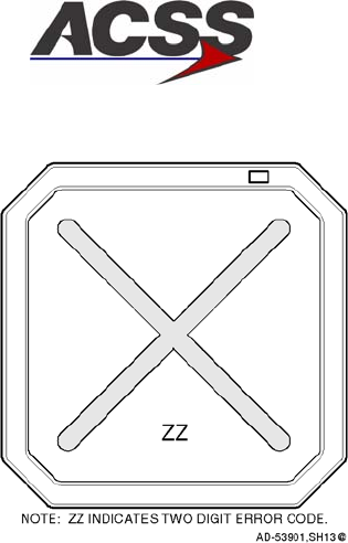
SYSTEM DESCRIPTION AND INSTALLATION MANUAL
TCAS 3000 Traffic Alert and Collision Avoidance System
34−43−23
Use or disclosure of information on this page is subject to the restrictions in the proprietary notice of this document.
Page 5−3
15 Dec 2005
Figure 5−1. VSI/TRA Fault Warning Display
4. System Self−Tests
A. Cockpit Display Test Modes
The TCAS 3000 System provides two types of test modes; a short functional test mode
and an extended maintenance test. Both test modes can be activated by the TEST
button or switch on the ATC/TCAS Control Panel. The short test mode can also be
activated by a central maintenance computer (CMC) or a central fault display interface
unit (CFDIU). The extended test mode can only be initiated at the end of the short test.
The short test mode is inhibited in the air if the Self−Test Inhibit programming pin
(RBP−8E) is grounded.
(1) Short Test Mode
The short test mode provides a flight deck initiated functional test of the TCAS RA
and TA displays and associated TCAS interfaces. It also provides an aural
annunciation of the TCAS system status.
The short test mode is available in all TCAS operational modes (Standby, TA Only, or
TA/RA) when on the ground. If a TA or RA occurs while airborne, the test is
terminated and normal operating status is resumed. The test mode is also
terminated if any of the Advisory Inhibit discrete inputs (grounds) are received on pins
RBP−5A, RBP−5B, RBP−5C, or RBP−5D.
Push and hold the TEST button/switch on the ATC/TCAS controller for a few seconds
to start the test. When the test mode becomes active, the words “tcas test” are
transmitted once aurally. In addition to the TCAS test pattern, RA indications and a
red TCAS TEST annunciation are displayed on the applicable display(s). Refer to
Figure 1−18 for a typical test pattern display on the VSI/TRA.

SYSTEM DESCRIPTION AND INSTALLATION MANUAL
TCAS 3000 Traffic Alert and Collision Avoidance System
34−43−23
Use or disclosure of information on this page is subject to the restrictions in the proprietary notice of this document.
Page 5−4
15 Dec 2005
At the completion of the test (8−seconds), the words “tcas test pass” should be
transmitted once aurally. In addition, the test pattern is removed from the display(s)
and a TCAS PASS annunciation is displayed. If the test fails, the words “tcas test
fail” are transmitted once aurally and a TCAS FAIL annunciation is displayed on the
applicable display(s).
If the TCAS short test fails, do the TCAS Computer Unit Self−Test procedures
referenced in paragraph 4.B. to determine which LRU or subsystem is not functioning
properly. To troubleshoot the system, refer to the procedures in the FAULT
ISOLATION section.
(2) Extended Test Mode
The extended test mode provides a flight deck initiated test that displays various
pages of text information that is selected by the ATC Mode S control panel 4096
code switches. This test mode is accessible only when on the ground and cannot be
initiated while airborne.
The extended test mode is used for maintenance purposes only. It displays various
pages of text information containing the TCAS software part number, fault messages,
status of program pins, analog and digital inputs, and other aircraft parameters.
To start the test, push and hold the TEST button/switch on the ATC/TCAS controller
for a minimum of 9 seconds. In addition the conditions that follow must occur:
•TCAS is in Standby
•The selected transponder is in Standby
•Aircraft is on the ground (The AIR/GND discrete [RMP−5K] is grounded)
•Landing gear is extended (Landing Gear discrete [RMP−13F] is grounded).
Once the extended test mode is established, the 4096 code switches on the
ATC/TCAS controller are used to select the desired maintenance page for display.
Table 5−3 lists the extended mode page names and numbers and the corresponding
4096 Ident Code number.

SYSTEM DESCRIPTION AND INSTALLATION MANUAL
TCAS 3000 Traffic Alert and Collision Avoidance System
34−43−23
Use or disclosure of information on this page is subject to the restrictions in the proprietary notice of this document.
Page 5−5
15 Dec 2005
Table 5−3. Extended Test Menu Selections
4096 Ident Code Number Page Page Name
0000 0 System Status
0001 1 Display Status
0002 2 Rad/Alt Status
0003 3 Xpdr Status
0004 4 Program Pins 1/3
0005 5 Program Pins 2/3
0006 6 Program Pins 3/3
0007 7 Help Reference
0011 11 Antenna Port Status
0012 12 Option Pins Status
0013 13 Part Numbers
All Other Codes Blank TCAS Test Menu
To view the TCAS test menu and system status pages along with the troubleshooting
messages, refer to the FAULT ISOLATION section.
To exit the extended test mode, set the ATC/TCAS mode selector switch to Mode S
ON.
B. TCAS Computer Unit Self−Test
(1) With all power off, reinstall the TCAS computer unit in its mounting tray. Make sure
the TCAS control panel and display(s) are also installed.
(2) Apply aircraft power and close all applicable TCAS system circuit breakers.
(3) Set the ATC/TCAS controller mode switch to Mode S ON.
(4) Push the PUSH TO TEST button on the TCAS computer unit front panel. The test
sequence that follows should occur:
•All TCAS computer unit front panel annunciators come on for a 3−second lamp
test
•If the TCAS is operational, the TCAS PASS green annunciator comes on for a
10−second display period and then goes off.
•If the TCAS is not operational, one or more of the red fault annunciators comes on
for a 10−second display period.
(5) If a fault is detected, refer to the Fault Isolation section for troubleshooting
information.

SYSTEM DESCRIPTION AND INSTALLATION MANUAL
TCAS 3000 Traffic Alert and Collision Avoidance System
34−43−23
Use or disclosure of information on this page is subject to the restrictions in the proprietary notice of this document.
Page 5−6
15 Dec 2005
5. Return to Service Test
Any time a TCAS LRU is removed and replaced following repair or maintenance, a return to
service test is required. The System Self−Test procedures referenced in paragraph 4.A. are
sufficient to check all system parameters.
6. Operational Software Loading Using an ARINC Portable Data Loader
When updating the TCAS 3000 Computer Unit with an ARINC portable data loader PDL,
verify the current TCAS 3000 Computer Unit software part number prior to continuing for
cockpit system only.
A. Current Software Verification
NOTE: Software verification using cockpit systems ONLY.
Verify the current software part number according to the extended maintenance
capabilities on status page code 0000 in the FAULT ISOLATION section of this manual or
the individual aircraft maintenance manual (refer to the onboard maintenance system
program).
B. Operational Software Loading (While Installed on Aircraft)
(1) Verify that the system inputs for AIR/GROUND (RMP−5K) and GEAR UP/DOWN
(RMP−13F) are grounded.
(2) Obtain an ARINC PDL and the appropriate interface cable for connecting the data
loader to the J1 (front) connector of the TCAS 3000 Computer Unit.
The following PDLs have been tested and found to be satisfactory for performing this
task:
•DEMO Systems − Part No. 30100 (Revision A and later versions)
•Teledyne − Part No. 2230915−01−D
•SFIM − Part No. YV68A110.
Other part numbers from these suppliers and ARINC 615 data loaders from other
manufacturers may perform the task successfully. However, ACSS can not verify
their usability.
(3) Shut off the PDL and remove power from the TCAS 3000 Computer Unit. Connect
the cable between the PDL and the J1 front connector on the TCAS 3000 Computer
Unit.
(4) Apply power to the TCAS 3000 Computer Unit.
(5) Turn on the PDL.
(6) Obtain the operational software. Insert disk No. 1 of the operational software into the
PDL for program uploading (or follow the applicable instructions for the PDL).

SYSTEM DESCRIPTION AND INSTALLATION MANUAL
TCAS 3000 Traffic Alert and Collision Avoidance System
34−43−23
Use or disclosure of information on this page is subject to the restrictions in the proprietary notice of this document.
Page 5−7
15 Dec 2005
(7) After the PDL indicates that the disk upload was successful, repeat step (6) for
multiple disks, if necessary.
(8) Wait at least 20 seconds after the last disk has finished uploading. Then turn off the
PDL, remove power from the TCAS 3000 Computer Unit, and disconnect the
interface cable.
(9) Apply power to the TCAS 3000 Computer Unit and ensure the TCAS system is fully
operational. Push the PUSH TO TEST button located on the front panel. The green
LED indicator on the front of the panel lights at the end of the test cycle
(approximately 8 seconds) to show the TCAS system is functional.
C. Compact Flash Card − (While Installed on Aircraft)
(1) Procedure For Uploading OPS SW Through Compact Flash Card
(a) Obtain the operational software.
(b) Verify that the aircraft is “on the ground” prior to performing an upload. The OPS
SW cannot be uploaded while the aircraft is airborne.
(c) Apply power to the TCAS 3000 computer unit.
(d) Open the CF card protective door located on the left side. (See Figure 5−2)
(e) Insert the CF card with the label facing the TCAS 3000 Computer unit front panel
LEDs. (See Figure 5−2)
(f) All LEDs will illuminate, which indicates TCAS 3000 Computer unit restart.
(g) All LEDs will extinguish and the XFER IN PROCESS LED will start to blink. The
blinking XFER IN PROCESS LED indicates that the unit is reading the CF card.
(h) The XFER IN PROCESS LED will indicate continuous green. The continuous
XFER IN PROCESS LED indicates that the unit is loading the contents of the CF
card. The loading process takes over one minute.
(i) Step NO TAGNO TAG(f), step NO TAGNO TAG(g), and step NO TAGNO TAG(h)
may repeat if the DL or FPGA files on the CF card are different than those
previously loaded on the TCAS 3000 Computer unit. If the files are not changed,
step NO TAGNO TAG(f), step NO TAGNO TAG(g), and
step NO TAGNO TAG(h) only occur once.
(j) When the upload is successful, the CF Load Status LED changes to a
continuous green indication.
(k) An unsuccessful upload is indicated by amber LEDs displayed during the upload
process. The LED correlations are listed in Table 5−4.
(l) Once the upload is successful, remove the CF card from the TCAS 3000
Computer unit front panel. (See Figure 5−3)
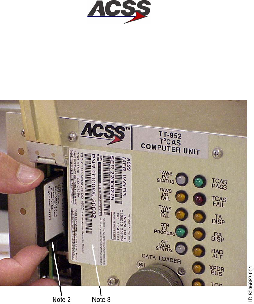
SYSTEM DESCRIPTION AND INSTALLATION MANUAL
TCAS 3000 Traffic Alert and Collision Avoidance System
34−43−23
Use or disclosure of information on this page is subject to the restrictions in the proprietary notice of this document.
Page 5−8
15 Dec 2005
(m) Close the compact flash (CF) card protective door.
(n) All LEDs will illuminate, which indicates a TCAS 3000 Computer unit restart.
(o) When all LEDs are extinguished, the unit is ready.
Figure 5−2. Compact Flash Card Access Port and LRU Identification Label
NOTES:
1. Image is shown as an example and may not be the same computer.
2. When inserting compact flash cards, make sure that the part numbers
on label are facing in the correct direction as shown in Figure 5−2.
Align the card with the slot and push in firmly. When removing, use
finger to push the ejector at the bottom of the slot until the card pops
out slightly on its own. After that, pull the card freely out of the slot.
3. Remove and replace software identification label as detailed in the
Accomplishment Summary of this Service Bulletin.
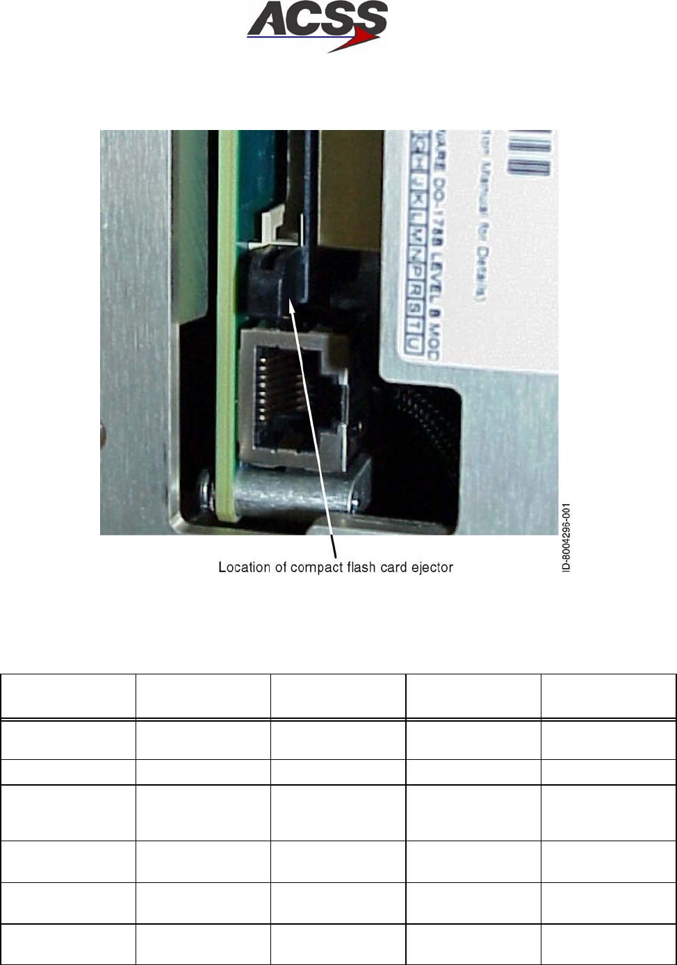
SYSTEM DESCRIPTION AND INSTALLATION MANUAL
TCAS 3000 Traffic Alert and Collision Avoidance System
34−43−23
Use or disclosure of information on this page is subject to the restrictions in the proprietary notice of this document.
Page 5−9
15 Dec 2005
Figure 5−3. Compact Flash Card Ejector Location
Table 5−4. Compact Flash Upload / LED Correlation
Triggering Event CF Status LED
XFER IN
PROCESS LED
Fault Type
Logged Ending Event
CF Card Inserted Blink CF UPLOAD
REQUEST
CRC 1 completed
Corrupt CF header Red CF FILE ERROR CF Card removed
Upload Card
Inserted while
Airborne
Red CF FILE ERROR CF Card removed
Incorrect
Configuration Error
Red CF FILE ERROR CF Card removed
Major/Minor
Incompatibility
Red CF FILE ERROR CF Card removed
File Header CRC
error
Red CF FILE ERROR CF Card removed

SYSTEM DESCRIPTION AND INSTALLATION MANUAL
TCAS 3000 Traffic Alert and Collision Avoidance System
34−43−23
Use or disclosure of information on this page is subject to the restrictions in the proprietary notice of this document.
Page 5−10
15 Dec 2005
Table 5−4. Compact Flash Upload / LED Correlation (cont)
Triggering Event Ending Event
Fault Type
Logged
XFER IN
PROCESS LED
CF Status LED
File does not exist
error
Red CF FILE ERROR CF Card removed
Multiple file error Red CF FILE ERROR CF Card removed
File Image CRC
error (CRC 1)
Red CF FILE ERROR CF Card removed
CRC 1 completed Green CF LOAD CF Card error is
detected or upload
completed or restart
Aborted Upload Red CF WRITE ERROR 10 seconds after
card removal
Airborne Upload Red CF FILE ERROR CF Card removed
Ground−to−air
transition during
upload
Green (per normal
uploading
sequence)
CF FILE ERROR CF Card error is
detected or upload
completed or restart
Flash Copy CRC
fails to match CF
File CRC (CRC 2)
Red CF WRITE ERROR Card removal
Flash Copy 2 fails
to match CRC at
Copy 1 location
Red FLASH EPROM
ERROR
Card removal
APM Calculated
CRC doesn’t match
CF File CRC.
Red APM WRITE
ERROR − CF
Upload
Card removal
APM Calculated
CRC doesn’t match
APM embedded
CRC.
Red APM DATA FAULT
− CF Upload
Card removal
APM write to Flash
unsuccessful
Red APM COPY WRITE
− CF Upload
Card removal
APM Calculated
CRC doesn’t match
APM embedded
CRC
Red APM Copy CRC −
CF Upload
Card removal
All files loaded
successful
Green CF UPLOAD SET
COMPLETE
Card removal

SYSTEM DESCRIPTION AND INSTALLATION MANUAL
TCAS 3000 Traffic Alert and Collision Avoidance System
34−43−23
Use or disclosure of information on this page is subject to the restrictions in the proprietary notice of this document.
Page 5−11
15 Dec 2005
D. Updated Software Verification
(1) Software Verification Using Cockpit Systems ONLY
Verify the updated software part number according to the TCAS 3000 extended
maintenance capabilities on status page code 0000 in the FAULT ISOLATION section
of this manual or the individual aircraft maintenance manual (refer to the onboard
maintenance system program).
(2) Software Verification Using a Stand−Alone PC ONLY
Verify the updated software part number using a stand−alone PC according to the
following procedure.
(a) Obtain PC software Part No. PS4088035−101.
(b) Obtain or build an RS−232 cable. (Refer to Figure 5−4.)
(c) Shut off the PC.
(d) Remove power from the TCAS 3000 Computer Unit.
(e) Connect the RS−232 cable from the PC (9−pin connector) to the J1 front
connector on the TCAS 3000 Computer Unit.
(f) Apply power to the TCAS 3000 Computer Unit.
(g) Power on the PC to Microsoft Windows operation.
(h) On the PC, go to START => PROGRAMS => ACSS TOOLS and double click
“TCAS Part Number”.
(i) Verify the updated TCAS software part number.
(j) Shut down the PC and remove power.
(k) Remove power from the TCAS 3000 Computer Unit.
(l) Disconnect the RS−232 cable from the J1 front connector on the TCAS 3000
Computer Unit.
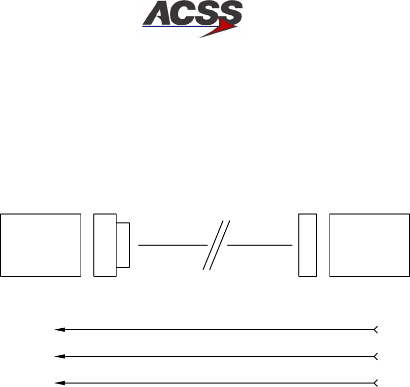
SYSTEM DESCRIPTION AND INSTALLATION MANUAL
TCAS 3000 Traffic Alert and Collision Avoidance System
34−43−23
Use or disclosure of information on this page is subject to the restrictions in the proprietary notice of this document.
Page 5−12
15 Dec 2005
40
ID−39471
TX 3
TCAS 2000
53 PIN
MALE
9 PIN
”D”
FEMALE
53 PIN 9 PIN ”D”
10 FEET MAX
BLACK
41 RX 2
WHITE
49 GND 5
SHIELD
NOTES:
Mating J1 front connector on the TCAS 2000 RT−950/−951 Computer Unit:
HI 4004295−160 or
ITT KJ6F18A53P or
MS27473E18A53P or
JT06RE−18−53P
Mating connector to the PC:
Standard 9−pin, D−submini connector with female contacts.
A single, twisted−pair, shielding wire using the shield as the common
ground is a popular wiring choice.
1.
2.
3.
Figure 5−4. RS−232 PC to TCAS Interface Cable

SYSTEM DESCRIPTION AND INSTALLATION MANUAL
TCAS 3000 Traffic Alert and Collision Avoidance System
34−43−23
Use or disclosure of information on this page is subject to the restrictions in the proprietary notice of this document.
Page 5−13
15 Dec 2005
(3) Software Verification Using a Software Verification Fixture ONLY
NOTE: Software versions prior to Change 7 can not be displayed on the Software
Verification Fixture.
(a) Obtain Software Verification Fixture (Part No. T326948−901) with associated
adapter cable (Part No. 200F−00084).
(b) Remove power to the TCAS 3000 Computer Unit.
(c) Connect the adapter cable (Part No. 200F−00084) to the TCAS 3000 Computer
Unit and the software verification fixture.
(d) Apply power to the TCAS 3000 Computer Unit.
(e) Enable the software verification fixture and verify the appropriate software part
number is displayed in the 15−digit display.
(f) Perform a TCAS system self−test and verify that TCAS TEST PASS is
annunciated.
NOTE: The TCAS TEST FAIL message may be annunciated if an LRU that
supplies input to the TCAS 3000 Computer Unit is not powered on.
(g) If the software part number is not displayed, repeat step (a) thru step (f).
(4) Software Verification Using a Remote Connected VSI/TRA ONLY
On some aircraft configurations, software verification may be performed using a
remote connected VSI/TRA (Part No. 4067241−861, −862, or −863) display attached
through adapter cable (Part No. 200F−00083) to the J1 front connector of the TCAS
3000 Computer Unit during the extended test mode.
Verify the particular aircraft configuration can support a cockpit initiated self−test and
be recognized at the 8−second time period after activation.
NOTE: CMC/CFDS activated self−test will not be recognized at the 8−second time
period, only an approved TCAS control panel.

SYSTEM DESCRIPTION AND INSTALLATION MANUAL
TCAS 3000 Traffic Alert and Collision Avoidance System
34−43−23
Use or disclosure of information on this page is subject to the restrictions in the proprietary notice of this document.
Page 5−14
15 Dec 2005
Blank Page

SYSTEM DESCRIPTION AND INSTALLATION MANUAL
TCAS 3000 Traffic Alert and Collision Avoidance System
34−43−23
Use or disclosure of information on this page is subject to the restrictions in the proprietary notice of this document.
Page 6−1
15 Dec 2005
FAULT ISOLATION
1. General
The TCAS 3000 Traffic Alert and Collision Avoidance System has three optional procedures
for fault detection and isolation to the LRU level. The first option uses the aircraft’s CMC or
central fault display system (CFDS) if the aircraft is equipped with an onboard maintenance
system. The second option uses a digital interface between the TCAS Computer Unit and the
display system (EFIS, multifunction display or VSI/TRA flat panel display). The third option
uses the annunciators located on the front panel of the computer unit. The annunciators are
activated by a self−test function within the TCAS Computer Unit. Select the procedural option
for fault isolation from paragraph 3., Procedure, which is applicable to the type of aircraft and
the equipment installed.
2. Equipment and Materials
NOTE:Equivalent alternatives are permitted for equipment in this list.
Digital Multimeter − Fluke Model 29, John Fluke Mfg Co. Inc., Everett, WA
3. Procedure
A. CMC or CFDS
Fault information can be displayed from an onboard maintenance system when the
aircraft is so equipped. Fault data is accessible only when the aircraft is on the ground.
Faults that occur at any time, on the ground or while airborne, are stored in fault memory
and reported to the CMC or CFDS. All displayed information is in the English language
with abbreviated terms used only as necessary. Refer to the appropriate CMC or CFDS
support manual for fault retrieval procedures.
B. TCAS Display System
The TCAS display system can be used to display system status and fail messages in the
cockpit, making it more convenient to use than the computer unit front panel annunciators
for a quick checkout of the TCAS system. In contrast with the computer unit self−test,
which records and stores faults from previous flights, the display system test shows only
current status and failure data.

SYSTEM DESCRIPTION AND INSTALLATION MANUAL
TCAS 3000 Traffic Alert and Collision Avoidance System
34−43−23
Use or disclosure of information on this page is subject to the restrictions in the proprietary notice of this document.
Page 6−2
15 Dec 2005
To access the cockpit display test modes, do the procedures that follow:
NOTES:
1. Fault detection with diagnostics can only be done on the ground. The pilot has
the option to do a pass/fail test while airborne if this feature is not inhibited.
2. This procedure is valid when used with either a single or dual control panel.
(1) Make sure the aircraft configuration indicates Aircraft On Ground and Gear Extended.
(2) Set the Mode Select switch on the ATC/TCAS control panel to STBY.
(3) Push and hold the TCAS TEST button for a minimum of 9 seconds.
(4) Set the transponder 4096 Ident Code Number to any code except 0000 thru 0007,
0011, 0012, 0013.
NOTE: Do not use codes 7500, 7600, or 7700; these code are reserved for
emergency operation.
(5) Make sure the TCAS TEST MENU is being displayed on the TCAS display. It should
match the screen shown in Figure 6−1.
(6) Set the transponder 4096 Ident Code Number to 0000.
(7) If the system passes, a maintenance page similar to that shown on Figure 6−2 is
displayed. A failure results in a referral to one or more specific ident codes. Set the
indicated code on the ATC/TCAS Control Panel and follow the instructions given.
(8) If the system passes, set the mode switch on the ATC/TCAS Control Panel to MODE
S ON. This allows you to exit the expanded test mode. If a failure is indicated, set
the transponder 4096 Ident Code to the codes indicated by the automatic referral
system. The remaining screens shown on Figure 2−4 thru Figure 2−14 are examples
of the other maintenance pages.
(9) Set system power to OFF and correct faults by replacing indicated LRUs or by
repairing faulty wiring harness.
(10) Test system as required after repair.

SYSTEM DESCRIPTION AND INSTALLATION MANUAL
TCAS 3000 Traffic Alert and Collision Avoidance System
34−43−23
Use or disclosure of information on this page is subject to the restrictions in the proprietary notice of this document.
Page 6−3
15 Dec 2005
C. TCAS Aural and VSI/TRA Annunciations
TCAS aural and VSI/TRA annunciations are given in Table 6−1.
Table 6−1. TCAS Aural and VSI/TRA Annunciations
VSI/TRA Annunciation
Condition Aural
Upper
Left
Upper
Right Center Color Notes
TRAFFIC Display
Control ON Mode
Normal Range ring and own
aircraft in view at all times,
along with qualifying
traffic.
TRAFFIC Display
Control AUTO
Mode
Normal Range ring and own
aircraft come up with
traffic when a TA or RA
exists.
Transponder Only
Mode
None TCAS
OFF
White TCAS is not operational.
STANDBY Mode None TCAS
OFF
White TCAS is not operational,
transponder is in standby.
Vertical Speed
Input Failure to
Single VSI (Dual
VSI Aircraft)
Normal RA FAIL
on failed
side
VSI FAIL
on failed
side
Yellow Vertical speed needle
removed from display with
failed data. No RAs
posted on failed side.
TCAS is operational on
remaining side.
VSI Input Failure
to Both (Dual VSI
Aircraft) or Single
VSI (Single VSI
Aircraft)
None VSI FAIL
on both
sides
TCAS
FAIL on
both sides
Yellow Vertical speed needle
removed from both VSIs
(dual VSI aircraft) or only
VSI (single VSI aircraft).
No RA information posted.
TCAS is not operational.
TA Only Mode Traffic −
Traffic
only
TA ONLY White
or
Yellow
Traffic alerts are the only
information displayed. No
RAs.
(The color changes from
white to yellow when a TA
actually occurs.)
Transponder or
Altitude Source
Fail
None TCAS
FAIL
Yellow TCAS is not operational.
Altitude Reporting
OFF
TCAS
OFF
White TCAS is not operational.
ATCRBS
Transponder
Selected
None TCAS
OFF
White TCAS is not operational.

SYSTEM DESCRIPTION AND INSTALLATION MANUAL
TCAS 3000 Traffic Alert and Collision Avoidance System
34−43−23
Use or disclosure of information on this page is subject to the restrictions in the proprietary notice of this document.
Page 6−4
15 Dec 2005
Table 6−1. TCAS Aural and VSI/TRA Annunciations (cont)
Condition Notes
VSI/TRA Annunciation
AuralCondition Notes
ColorCenter
Upper
Right
Upper
Left
Aural
RA Only
(TA Display
Control to OFF)
RA ONLY White VSI/TRA displays
resolution advisories only.
RA Fail RA FAIL VSI FAIL Yellow No resolution advisories
displayed.
Traffic Display
Failure
TD FAIL Yellow No traffic advisories
displayed.
Single VSI/TRA
Failure (Dual VSI
Aircraft)
Normal X across
failed
display
Red On failed side, all
symbology removed and
replaced with a large red
X and hex−coded failure
number. TCAS
operational on good side.
Dual VSI/TRA
Failure (or Single
on Single VSI
Aircraft)
None X across
both
displays
Red All symbology removed
from both displays and
replaced with a large red
X and failure code. TCAS
is not operational.
Cockpit Lamp
Test
Normal Display full
white
During cockpit lamp test,
display goes full white and
displays no symbology.
TCAS SELF TEST (Note 1.)
TCAS Test Mode
(First Second)
TCAS
TEST
TCAS
TEST
White TCAS system self test.
TCAS Test Mode
(2 to 8 Seconds)
TCAS
TEST
White TCAS test pattern shown.
TCAS Test Mode
(at 8 Seconds)
TCAS
TEST
PASS/
FAIL
TCAS
TEST
TCAS test pattern
removed and TCAS
returns to normal
operation unless the test
switch is held, the aircraft
is on the ground, and
TCAS is in STBY.
SYSTEM DESCRIPTION AND INSTALLATION MANUAL
TCAS 3000 Traffic Alert and Collision Avoidance System
34−43−23
Use or disclosure of information on this page is subject to the restrictions in the proprietary notice of this document.
Page 6−5
15 Dec 2005
Table 6−1. TCAS Aural and VSI/TRA Annunciations (cont)
Condition Notes
VSI/TRA Annunciation
AuralCondition Notes
ColorCenter
Upper
Right
Upper
Left
Aural
TCAS EXTENDED SELF TEST (MAINTENANCE ONLY) (Note 2.)
TCAS Extended
Test Mode (Test
Switch Held at 7
Seconds for 2
Seconds and
Aircraft on the
Ground Only)
System
information
pages
White Current status of the
TCAS system,
transponder, antennas,
radio altimeters.
barometric altitude, etc is
presented in a series of
pages called by selection
of 4096 code.
NOTES:
1. Self Test should only be run in STANDBY mode in flight or on the ground.
2. Extended Self Test provides maintenance information on seven screens selected using 4096
code. This mode is available only on the ground and in STANDBY. Extended Self Test ends
automatically with a TCAS/Transponder mode change or if the aircraft becomes airborne.
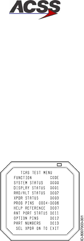
SYSTEM DESCRIPTION AND INSTALLATION MANUAL
TCAS 3000 Traffic Alert and Collision Avoidance System
34−43−23
Use or disclosure of information on this page is subject to the restrictions in the proprietary notice of this document.
Page 6−6
15 Dec 2005
D. TCAS Test Menu and System Status Pages
The extended test mode provides maintenance information on the TCAS display. Pages
are selected by 4096 codes on the transponder control panel. The extended test mode is
accessible only on the ground, with the transponder in standby.
To start the extended test mode, select STBY and push the transponder control panel
TCAS TEST switch for 8 seconds. To exit the extended test mode, move the transponder
mode control out of STBY.
(1) TCAS Test Menu
The TCAS Menu Page, Figure 6−1, can be displayed whenever a TCAS suppression
bus failure is not indicated and the 4096 Ident Code is any code other than 0000 thru
0007, 0011, 0012, or 0013. If a TCAS suppression bus failure is indicated, all 4096
Ident Codes other than 0000 thru 0007, 0010 thru 0013 and 0510 can be used to
select the TCAS Test Menu.
Figure 6−1. TCAS Test Menu Page
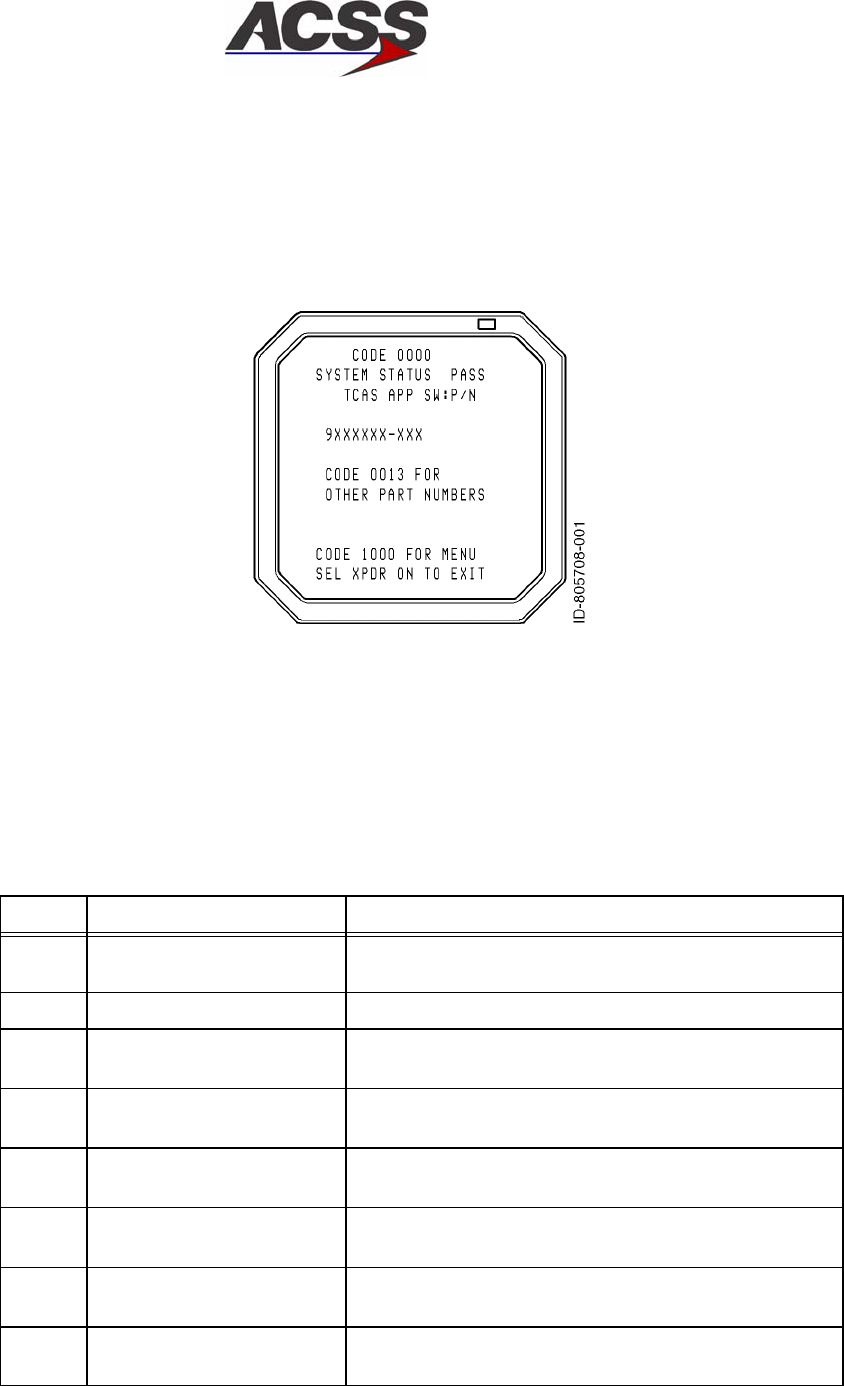
SYSTEM DESCRIPTION AND INSTALLATION MANUAL
TCAS 3000 Traffic Alert and Collision Avoidance System
34−43−23
Use or disclosure of information on this page is subject to the restrictions in the proprietary notice of this document.
Page 6−7
15 Dec 2005
(2) System Status Page
Selection of code 0000 displays the System Status page, Figure 6−2. This page
displays the PASS or FAIL status of the TCAS system and the current version of the
operating software loaded into the TCAS computer.
Figure 6−2. Typical System Status Page
In the event of a detected system failure, one or more of the messages in Table 6−2
are displayed. Lines 6 thru 10 of the display screen are used to display the five
highest priority faults within the TCAS system. A maximum of five messages can be
displayed.
Table 6−2. System Status Page Fault Messages
Priority Message Description
1SUPP FAULT GOTO 0010 Suppression bus failure. Select page 0010 for more
information.
2TCAS CU FAIL TCAS computer unit has failed BITE test.
3ANT FAIL TOP Antenna failure. Message field will display TOP, BOT
or BOTH to indicate which antenna failed.
4DISP FAIL GOTO 0001 TCAS has lost valid signal from display. Select page
0001 for more information.
5RALT INACT GOTO 0002 TCAS has lost valid signal from radio altimeter.
Select page 0002 for more information.
6XPDR FAIL GOTO 0003 TCAS has lost valid signal from Mode S transponder.
Select page 0003 for more information.
7ANT FAIL GOTO 0011 One of the antenna ports connected to the TCAS CU
has failed. Select page 0011 for more information.
8OPT FAIL GOTO 0012 Parity for the option selections has failed. Select
page 0012 for more information.
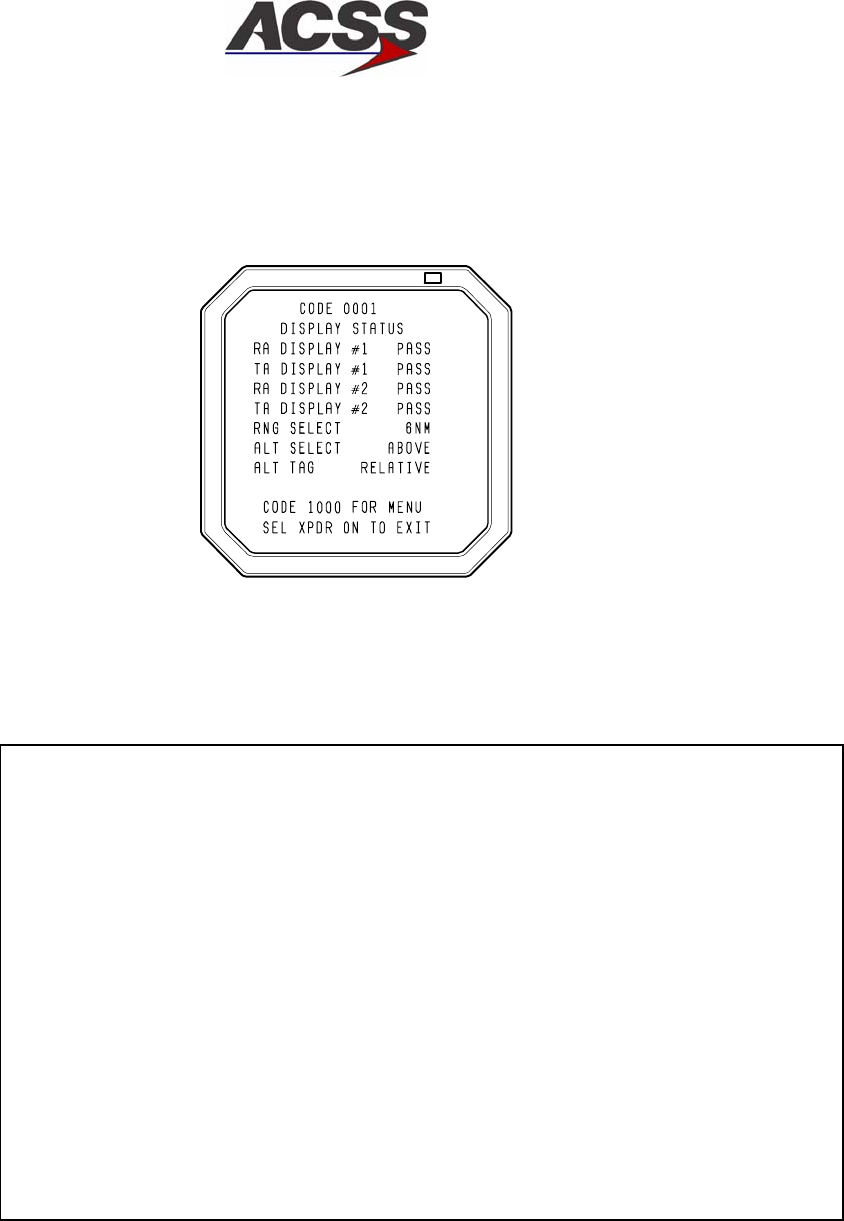
SYSTEM DESCRIPTION AND INSTALLATION MANUAL
TCAS 3000 Traffic Alert and Collision Avoidance System
34−43−23
Use or disclosure of information on this page is subject to the restrictions in the proprietary notice of this document.
Page 6−8
15 Dec 2005
(3) Display Status Page
Selection of code 0001 displays the Display Status page, Figure 6−3. This page
displays the current status of the Resolution Advisory and Traffic Advisory displays.
AD−53901,SH2@
Figure 6−3. Typical Display Status Page
The message contents for the Display Status page are determined as follows:
RA DISPLAY #1 PASS Indicates valid signal (ground/low) is present at TCAS CU pin
RMP−14C. Fail is displayed if this signal is an open/high.
TA DISPLAY #1 PASS Indicates valid signal (ground/low) is present at TCAS CU pin
RMP−7E. FAIL is displayed if this signal is an open/high.
RA DISPLAY #2 PASS Indicates valid signal (ground/low) is present at TCAS CU pin
RMP−13E. FAIL is displayed if this signal is an open/high.
TA DISPLAY #2 PASS Indicates valid signal (ground/low) is present at TCAS CU pin
RMP−7J. FAIL is displayed if this signal is an open/high.
RNG SELECT 6NM Indicates current range selection for the traffic display. For
installations using control panels without range select
switches, range defaults to 6NM.
ALT SELECT NORM Indicates current selection of vertical display limits for traffic
display − NORM, BELOW, or ABOVE. For installations that
use control panels without ABV−NORM−BLW switch, limits
default to NORM.
ALT TAG RELATIVE Indicates current selection on control panel for type of traffic
symbol altitude indication, RELATIVE or FLT LVL. Default is
RELATIVE if no switch is available on control panel.
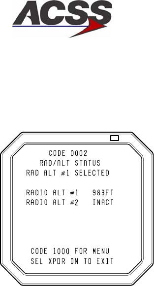
SYSTEM DESCRIPTION AND INSTALLATION MANUAL
TCAS 3000 Traffic Alert and Collision Avoidance System
34−43−23
Use or disclosure of information on this page is subject to the restrictions in the proprietary notice of this document.
Page 6−9
15 Dec 2005
(4) RAD/ALT Status Page
Selection of code 0002 displays the RAD/ALT Status page, Figure 6−4. This page
displays the status of the selected radio altimeter interface to the TCAS.
AD−53901,SH3@
Figure 6−4. Typical RAD/ALT Status Page
The first information line (line 3) of the RAD/ALT STATUS page indicates which of the
two radio altimeter ports is being used by the TCAS computer. The TCAS computer
attempts to use radio altimeter No. 1 first. If it determines this input is invalid, it
automatically switches to radio altimeter No. 2.
The current status of the two radio altimeter ports is displayed on lines 5 and 6. If a
signal is valid, the radio altitude value is displayed in either “FT” for English type
altimeters, or “M” for Metric type altimeters.
If one of the radio altitude signals is determined to be invalid, the altitude value is
replaced by INACT. Radio altitude INACT indicates the radio altimeter has failed, is
not powered, or is not connected.
The radio altimeter input is determined to be invalid if, for an analog radio altimeter
input, 28 V dc valid is not present at TCAS CU pin RMP−2K for Radio Alt #1 or pin
RMP−3C for Radio Alt #2, or for a digital radio altimeter input, the sign status matrix
(SSM) of the radio altimeter output indicates not valid or no data is present on the
digital bus.
If the radio altimeter output is greater than 2200 feet (source is valid, but data is
invalid), the radio altitude value is replaced by OVR RNG.
When both radio altitude sources are invalid, line 3 is blank.
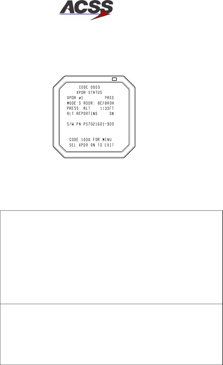
SYSTEM DESCRIPTION AND INSTALLATION MANUAL
TCAS 3000 Traffic Alert and Collision Avoidance System
34−43−23
Use or disclosure of information on this page is subject to the restrictions in the proprietary notice of this document.
Page 6−10
15 Dec 2005
(5) Transponder (XPDR) Status Page
Selection of code 0003 displays the XPDR Status page, Figure 6−5. This page
displays data for the transponder selected at the time the extended test mode was
entered.
AD−53901,SH4@
Figure 6−5. Typical Transponder (XPDR) Status Page
The message contents for the XPDR Status page are determined as follows:
XPDR #1 PASS Indicates PASS or FAIL status of the selected transponder
(XPDR #1 or XPDR #2) as indicated by the digital
transmission from that transponder. FAIL is displayed if no
data is received on the bus.
MODE S ADDR: 8E78A0H Indicates the Mode S address (in hexadecimal format) of the
selected transponder as determined by program pins at the
rear connector of the transponder. (See Note 1.)
PRESS. ALT 1133FT Indicates the last pressure altitude being reported by the
selected Mode S transponder before the TCAS system was
placed into STBY. This value is not updated while in extended
test mode.
ALT
REPORTING
ON Indicates current position of altitude reporting switch on Mode
S/TCAS control panel − ON or OFF.
S/W PN PS7021601−903 (See Note 2.)
NOTES:
1. If the transponder detects either all 1’s or all 0’s, the following message will appear
− ILLEGAL ADDRESS −. In addition, a fail message will appear on the front of the
transponder and on Extended Test. The message reads CHECK DISCRETE
ADDR WIRING ON XPDR PINS MP1A THROUGH MP3D.
2. The S/W PN information, line 8 of the display screen, displays general text supplied
by the ACSS ATDL transponder via label 356 (block transfer), which is equipped to
supply the text to the display. If a transponder is installed that does not have this
feature, line 8 is blank.
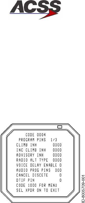
SYSTEM DESCRIPTION AND INSTALLATION MANUAL
TCAS 3000 Traffic Alert and Collision Avoidance System
34−43−23
Use or disclosure of information on this page is subject to the restrictions in the proprietary notice of this document.
Page 6−11
15 Dec 2005
(6) Programming Pins Status Pages
The following three displays indicate the status of various option programming pins
located in the rear connector of the TCAS computer. The 1s and 0s following a
programming option indicate the GROUND or OPEN status for those programming
pins. Each 1 and 0 is associated with a program pin. A one (1) indicates the pin is
grounded by connecting to a program common pin on the TCAS connector or to an
aircraft ground. A zero (0) indicates the pin is left open.
Selection of code 0004 displays the first of three pages that define program pin
status. See Figure 6−6.
Figure 6−6. Typical Program Pins 1/3 Page

SYSTEM DESCRIPTION AND INSTALLATION MANUAL
TCAS 3000 Traffic Alert and Collision Avoidance System
34−43−23
Use or disclosure of information on this page is subject to the restrictions in the proprietary notice of this document.
Page 6−12
15 Dec 2005
Programming pins on the TCAS computer associated with each of the functions
defined on the page 1 display are listed below. Where more than one program pin is
indicated, the listed connector pins correspond to the display digits read from left to
right. A one (1) indicates the associated pin is grounded. A zero (0) indicates open.
CLIMB INH 0000 Climb Inhibit inputs:
RMP−1J, RMP−13G, RBP−5J, RBP−5K.
INC CLIMB INH 0000 Increase Climb Inhibit inputs:
RBP−5E, RBP−5F, RBP−5G, RBP−5H
ADVISORY INH 0000 Advisory Inhibit inputs:
RBP−5A, RBP−5B, RBP−5C, RBP−5D
RADIO ALT TYPE 10000 Analog Radio Altimeter Type: RMP−12B
ARINC 552/552A (0), Collins BCA (1)
VOICE DELAY
ENABLE
0 Voice Delay option: RBP−7D
Enabled = (1), Disabled = (0)
AUDIO PROG PINS 000 Audio output level selection inputs:
RBP−7A, RBP−7B, RBP−7C
CANCEL DISCRETE 20 Advisory Cancel Discrete option: RMP−3D
(0) allows advisories to be cancelled. A (1) does not allow
advisories to be cancelled.
DTIF PIN 0 TBD
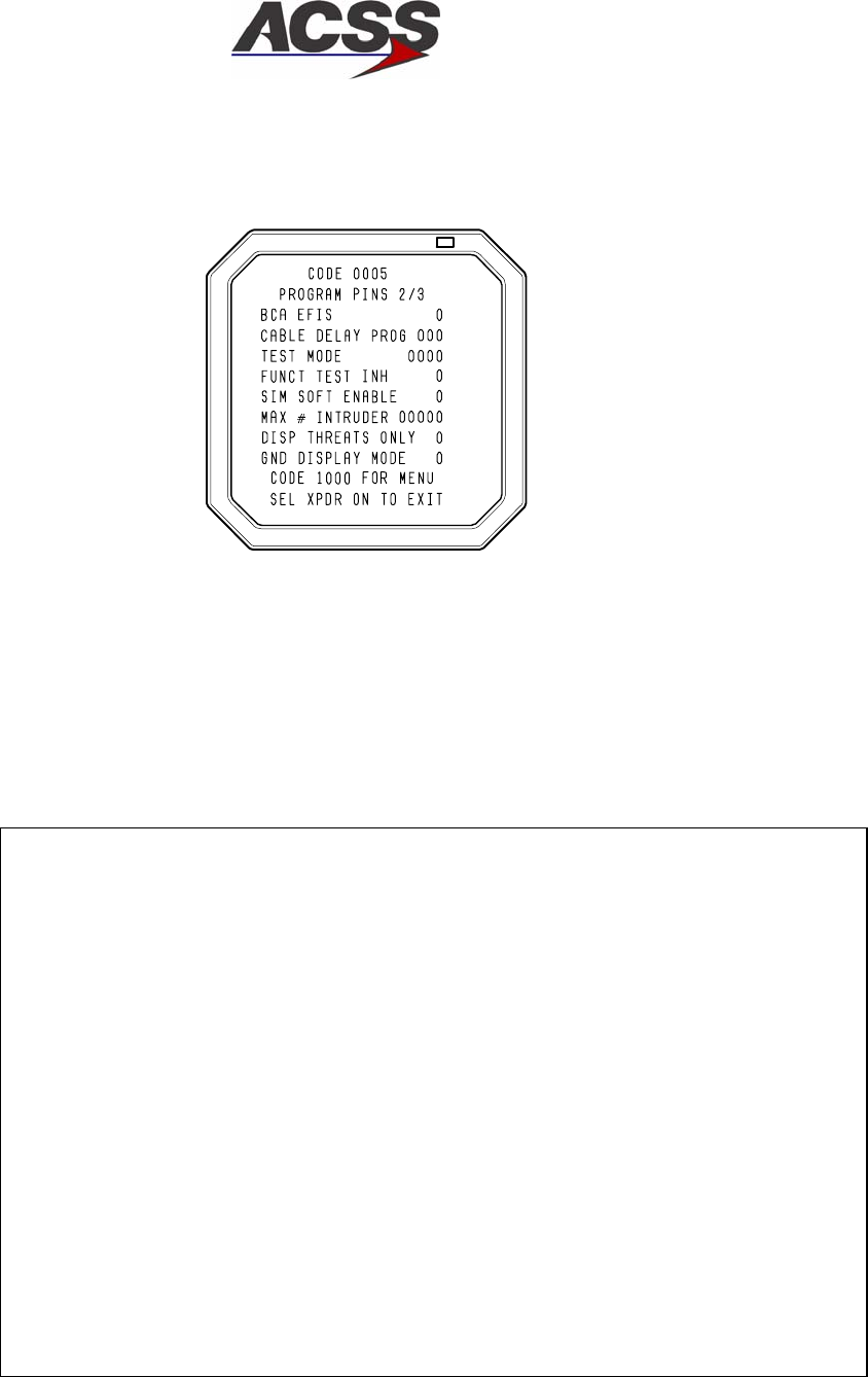
SYSTEM DESCRIPTION AND INSTALLATION MANUAL
TCAS 3000 Traffic Alert and Collision Avoidance System
34−43−23
Use or disclosure of information on this page is subject to the restrictions in the proprietary notice of this document.
Page 6−13
15 Dec 2005
Selection of code 0005 displays the second of three pages that define the Program
Pins status. See Figure 6−7.
AD−53901,SH6@
Figure 6−7. Typical Program Pins 2/3 Page
Programming pins on the TCAS computer associated with each of the functions
defined on the Program Pins 2/3 page are listed below. Where more than one
program pin is indicated, the listed connector pins correspond to the display digits
read from left to right. A one (1) indicates the associated pin is grounded. A zero (0)
indicates open.
BCA EFIS 0RA/TA block transfer program that determines the type of
data transfer from the TCAS CU to the TA/RA displays:
A (1) indicates ACSS BCA EFIS format. A (0) indicates
ARINC 735 format: RMP−12C.
CABLE DELAY
PROG
000 RF delay compensation program for antenna cable length
difference (top versus bottom): RBP−7G, RBP−7H, RBP−7J
TEST MODE 0000 Shop test function (all 0s for flight mode):
RBP−9D, RBP−9E, RBP−9F, RBP−9G
FUNCT TEST INH 0 Inhibits cockpit self−test when airborne (0 for no inhibit):
RBP−8E
SIM SOFT ENABLE 0 Simulator Software Enable input: RBP−10K
Should always be (0) for flight mode
MAX # INTRUDER 00000 Select maximum number of traffic symbols displayed on VSI.
Value for each digit, from left to right, is 16, 8, 4, 2, 1. The
maximum number is the sum of not selected values (0s):
RBP−8F, RBP−8G, RBP−8H, RBP−8J, RBP−8K.
DISP THREATS
ONLY
0 Selects display of traffic only when TAs or RAs occur:
(0 indicates display of any traffic): RBP−7F.
GND DISPLAY
MODE
0Selects TCAS OFF automatically with aircraft ON GROUND
(0 indicates TCAS active ON GROUND): RBP−7E.
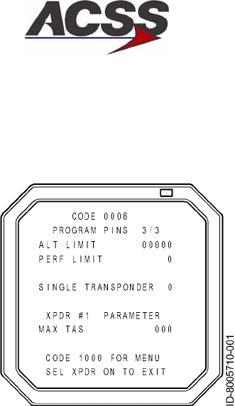
SYSTEM DESCRIPTION AND INSTALLATION MANUAL
TCAS 3000 Traffic Alert and Collision Avoidance System
34−43−23
Use or disclosure of information on this page is subject to the restrictions in the proprietary notice of this document.
Page 6−14
15 Dec 2005
Selection of code 0006 displays the third of three pages that define the Program
Pins status. See Figure 6−8.
Figure 6−8. Typical Program Pins 3/3 Page

SYSTEM DESCRIPTION AND INSTALLATION MANUAL
TCAS 3000 Traffic Alert and Collision Avoidance System
34−43−23
Use or disclosure of information on this page is subject to the restrictions in the proprietary notice of this document.
Page 6−15
15 Dec 2005
Programming pins on the TCAS computer associated with each of the functions
defined on the Program Pins 3/3 page are listed below. Where more than one
program pin is indicated, the listed connector pins correspond to the display digits
read from left to right. A one (1) indicates the associated pin is grounded and a zero
(0) indicates open, except for RCZ−852 MAX TAS where a one (1) indicates an open
and a zero (0) indicates a ground.
ALT LIMIT 00000 Shows selected altitude above which TCAS will not give CLIMB
commands. Value for each digit, from left to right, is 32000, 16000,
8000, 4000, and 2000 feet. Altitude is the sum of selected values
(1s): RMP−6J, RMP−6H, RMP−6G, RMP−6F, RMP−6E.
PERF LIMIT 0 Selects CLIMB command altitude limit control from external
performance computer: A ground (1) indicates performance/climb
rate is not limited. An open (0) indicates performance/climb rate is
limited: RMP−6D.
SINGLE
TRANS−
PONDER
0 Shows if the TCAS 3000 is configured for a single transponder. (1)
indicates a single transponder . (0) indicates not a single
transponder.
MAX TAS 000 Shows the selected maximum airspeed operating range of aircraft.
This data is obtained from ARINC label 276 of the selected
transponder. Refer to the appropriate Mode S transponder
installation manual.
NOTE: Line 8 of the Program Pins 3/3 display indicates which transponder is currently
selected.
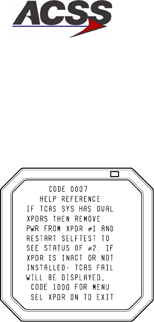
SYSTEM DESCRIPTION AND INSTALLATION MANUAL
TCAS 3000 Traffic Alert and Collision Avoidance System
34−43−23
Use or disclosure of information on this page is subject to the restrictions in the proprietary notice of this document.
Page 6−16
15 Dec 2005
(7) Help Reference Page
Selection of code 0007 displays the Help Reference page, Figure 6−9. This page
serves as a reference to assist aircraft maintenance personnel in checking the
functionality of dual transponders.
AD−53901,SH8@
Figure 6−9. Help Reference Page
In addition to the recommended procedure, the number 2 transponder must be
selected on the Mode S/TCAS control panel and the mode select switch placed in TA
only or TA/RA mode momentarily prior to restarting self-test to enter extended
maintenance mode.

SYSTEM DESCRIPTION AND INSTALLATION MANUAL
TCAS 3000 Traffic Alert and Collision Avoidance System
34−43−23
Use or disclosure of information on this page is subject to the restrictions in the proprietary notice of this document.
Page 6−17
15 Dec 2005
(8) Suppression Bus Fail Page
The Suppression Bus Fail page, Figure 6−10, is displayed only when a TCAS
suppression bus failure is indicated and the 4096 Ident Code is 0010. This page
displays information about detected suppression bus failures. It briefly describes the
problem and instructs maintenance personnel to change the 4096 Ident Code to
display the Suppression Bus Clear page for clearing instructions. If there is no
suppression bus failure, the main menu (0000) is displayed.
AD−53901,SH9@
Figure 6−10. Suppression Bus Fail Page
The flight crew may report a unique problem of an intruder displayed which appears
to be co−altitude, located on the own aircraft symbol. In many of these cases, TCAS
may issue a TA followed by an RA. After the flightcrew has initiated the advisory, the
intruder may not appear to change relative to the own aircraft symbol.
In this type of report, a failure in the mutual suppression bus, which connects the own
aircraft transponder to the TCAS CU, could result in the TCAS CU developing an
intruder track file on its own associated transponder. Simply performing a DC
continuity test of the connection between the TCAS CU and the transponders may
not identify the problem. In many cases, a connector termination or pushed back pin
may be the cause.
That is why it is very important to be monitoring the suppression signal from the
active source, on both ends. The following is one method to monitor the signal.
Remove the TCAS CU and the non−selected transponder. With an oscilloscope,
monitor the signal at the TCAS CU rack rear connector for the Mode S transponder
suppression signal related to the squitter message sent every second by the selected
operational transponder.
Repeat the same test with the second transponder after removing the first
transponder. To test the TCAS CU suppression pulse, install the TCAS CU, remove
the No. 1 transponder and monitor the TCAS suppression pulse during the time of
the UF16 broadcast or the WSS while in the air (if possible). This TCAS suppression
signal should also be present on the No. 2 transponder.
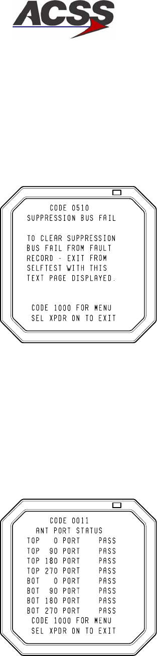
SYSTEM DESCRIPTION AND INSTALLATION MANUAL
TCAS 3000 Traffic Alert and Collision Avoidance System
34−43−23
Use or disclosure of information on this page is subject to the restrictions in the proprietary notice of this document.
Page 6−18
15 Dec 2005
(9) Suppression Bus Clear Page
The Suppression Bus Clear page, Figure 6−11, is displayed only when a TCAS
suppression bus failure is indicated and the 4096 Ident Code is 0510. This page
briefly describes how to clear suppression bus failures from the fault record by exiting
the extended test mode with this page displayed. When the TCAS extended test is
exited, the failure indication is cleared and a Suppression Bus Clear code is recorded
in the current flight leg.
AD−53901,SH10@
Figure 6−11. Suppression Bus Clear Page
(10) Antenna Port Status Page
Selection of code 0011 displays the Antenna Port Status page, Figure 6−12. This
page displays the current operational status of the top and bottom TCAS antennas.
The status of each port is indicated as PASS when valid and FAIL when invalid.
Information lines 8, 9, and 10 are not displayed when an omnidirectional bottom
antenna is installed.
AD−53901,SH11@
Figure 6−12. Typical Antenna Port Status Page
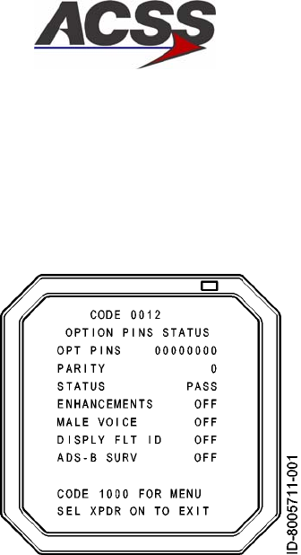
SYSTEM DESCRIPTION AND INSTALLATION MANUAL
TCAS 3000 Traffic Alert and Collision Avoidance System
34−43−23
Use or disclosure of information on this page is subject to the restrictions in the proprietary notice of this document.
Page 6−19
15 Dec 2005
(11) Option Pins Status Page
Selection of code 0012 displays a page that defines the TCAS computer option pins.
See Figure 6−13.
Figure 6−13. Typical Option Pins Status Page
Option pins on the TCAS computer associated with each of the functions defined on
the Option Pins Status page are listed below. Where more than one option pin is
indicated, the listed connector pins correspond to the display digits read from left to
right.
There are eight option pins available on the TCAS computer for selection of various
options. The OPT PINS are as follows: RMP−10G, −10H, −10J, −10K, −11A, −11B,
−11C, and −11D.
NOTE: OPT PINS RMP−10G, −10H, −10J, and −10K are reserved for future
enhancements and are used for parity check only.
The PARITY line (line 4) displays the status of the parity program pin (RMP−12G).
Pin RMP−12G must be grounded (1) when the number of OPT PINS grounded is an
odd number (1, 3, 5, 7). If number of OPT PINS grounded is an even number (0, 2,
4, 6, 8), then pin RMP−12G should be open (0).
The STATUS line (line 5) displays FAIL if the option pins parity is incorrect or PASS if
parity is correct.
The ENHANCEMENTS line (line 6) displays the status of the Flight Data Recorder
ARINC 429 and Extended Maintenance Log Program input status (Pin RMP−11D).
This option enables the use of the Flight Data Recorder and the down loading of the
extended maintenance log through a PDL connected to connector J1 located on the
front of the TCAS computer. If pin RMP−11D is open, the Flight Data Recorder is not
used and normal RA display bus operation occurs. If pin RMP−11D is grounded,
high speed ARINC 429 flight data is output on the RA Display #1 and #2 busses and
maintenance log data can be downloaded through a portable data loader.
SYSTEM DESCRIPTION AND INSTALLATION MANUAL
TCAS 3000 Traffic Alert and Collision Avoidance System
34−43−23
Use or disclosure of information on this page is subject to the restrictions in the proprietary notice of this document.
Page 6−20
15 Dec 2005
The MALE VOICE line (line 7) displays the Male Voice Program input status (Pin
RMP−11C). This option allows audio annunciation to be selectable for either male or
female gender. If pin RMP−11C is grounded, the male voice option is enabled (ON).
If pin RMP−11C is open, the female voice option is enabled (OFF).
The DISPLAY FLT ID line (line 8) displays the Flight ID Program input status (Pin
RMP−11B). This program allows flight identification from the transponder to be
output on traffic display busses. If pin RMP−11B is grounded, Flight ID Display is
enabled (ON). If pin RMP−11B is open, Flight ID Display is disabled (OFF).
The ADS−B SURV line (line 9) displays the ADS−B surveillance program input status
(Pin RMP−10K). This program allows the passive tracking of intruders who squitter
ADS−B squitters containing position information. If pin RMP−10K is grounded, the
ADS−B surveillance option is enabled (ON). If pin RMP−10K is open, the ADS−B
surveillance option is disabled (OFF). To activate this option, the TCAS CU must also
have hardware MOD C installed.
(12) Part Numbers Page
Selection of code 0013 displays the Part Numbers Page, Figure 6−14. This page
displays the software part numbers loaded on the TCAS Computer.
Figure 6−14. Typical Option Pins Status Page
E. TCAS Computer Unit Self−Test
The TCAS computer unit detects system faults and displays them on its front panel
annunciators. Its flight leg memory stores system status and fault information for 10
consecutive flight legs. A flight leg is the interval between weight−off−wheels and weight−
on−wheels during which TCAS is operative. By recalling the stored data, ground
maintenance personnel can evaluate in−flight performance on the ground and fault
isolate a current or previous failure to a specific LRU or LRU interface.
Table 6−3 summarizes how the TCAS computer unit self−test is activated at power−up,
during operation, and during commanded self−test. The computer unit can activate the
commanded self−test only when the aircraft is on the ground.

SYSTEM DESCRIPTION AND INSTALLATION MANUAL
TCAS 3000 Traffic Alert and Collision Avoidance System
34−43−23
Use or disclosure of information on this page is subject to the restrictions in the proprietary notice of this document.
Page 6−21
15 Dec 2005
Table 6−4 lists the functions of the computer unit’s status annunciators and the
corresponding troubleshooting actions. If the annunciators indicate an antenna problem,
the antenna connections should be checked by measuring the antenna resistance values
at the computer unit mounting tray. The resistance values listed in Table 6−5 are
measured between the center conductor and shield on each LTP and LMP antenna
connector.
Table 6−3. Computer Unit Self−Test Execution
Test Sequence Activation Test Indications
Power On Self−Test Self−Test is activated with
each application of system
power
No indication unless a fault is detected.
System status/fault data is stored in memory
for 10 consecutive flight legs. Data can be
recalled by doing the commanded self−test on
the ground.
Continuous Self−Test Executed automatically as
part of normal TCAS inflight
operation
No indication unless a fault is detected.
System status/fault data is stored in memory
for 10 consecutive flight legs. Data can be
recalled by doing the commanded self−test on
the ground.
Commanded
Self−Test
Push the front panel PUSH
TO TEST button
•All front panel lamps come on during a
3−second lamp test.
•If the TCAS is operational, the TCAS PASS
green lamp comes on for a 10−second
display period and then goes off.
•If the TCAS is not operational, one or more
red fault lamps come on for a 10−second
display period. Refer to Table 6−4 for
corrective action.
Push the PUSH TO TEST
button again before the
previous 10−second display
period has elapsed
•Previous fault display is aborted
•All lamps come on during a 1−second lamp
test
•Status/fault data recorded during the
preceding flight leg is displayed for
10−seconds.
Push the PUSH TO TEST
button before the end of each
succeeding display period
•Status/fault data recorded during a total of
10 flight legs (maximum) is displayed
•When data from the earliest recorded flight
leg has been displayed, all lamps flash at a
2.5−Hz rate for 3−seconds if the PUSH TO
TEST button is pushed. This indicates the
end of recorded test data.

SYSTEM DESCRIPTION AND INSTALLATION MANUAL
TCAS 3000 Traffic Alert and Collision Avoidance System
34−43−23
Use or disclosure of information on this page is subject to the restrictions in the proprietary notice of this document.
Page 6−22
15 Dec 2005
Table 6−4. Computer Unit Fault Reporting and Corrective Actions
Status
Annunciator Failure Possible corrective Action
TCAS
PASS
The TCAS Computer Unit
passes its own internal BITE
test
TCAS computer unit is operational. If other
annunciators are on, the problem is in the indicated
subsystem or aircraft wiring.
TCAS
FAIL
The TCAS Computer Unit has
failed its own internal BITE
test
Replace the TCAS computer unit.
TOP
ANT
The top antenna DC
resistance test indicates a
failure
Remove the TCAS computer unit. Use a multimeter
to measure the DC resistances indicated in Table 6−5
for the top antenna. Repair antenna cables or replace
the antenna as required.
BOT
ANT
The bottom antenna DC
resistance test indicates a
failure
Remove the TCAS computer unit. Use a multimeter
to measure the DC resistance indicated in Table 6−5
for the bottom antenna. Repair antenna cable(s) or
replace the antenna as required.
HDG Heading input function not
used
Not applicable
TA
DISP
Traffic advisory display
discrete signals No.1 or No.2
indicate a failure
Check wiring and power to TA display. (On both sides
of the cockpit, if two are installed.) Make sure that
RA/TA valid discrete 1 and 2 (RMP−7E and RMP−7J)
are <3.5 V dc to ground. Repair wiring or replace
display as required.
RA
DISP
Resolution advisory display
discrete signals No.1 or No.2
indicate a failure
Check wiring and power to RA displays. Make sure
that RA valid discrete 1 and 2 (RMP−14C and
RMP−13E) are <3.5 V dc to ground. Repair wiring or
replace display as required.
RAD
ALT
Radio altitude source No.1 or
No.2 is invalid or has failed
Check wiring and power to the radio altimeters. For
analog radio altimeters, make sure the RAD ALT No.1
and No.2 valid discrete (RMP−2K and RBP−3C) are
>18.5 V dc. Repair wiring or replace radio altimeter
as required.
XPDR
BUS
Mode S Transponder No.1 or
No.2 is invalid or has failed.
Check wiring and power to the transponders. Check
for data on XT 429 bus No.1 and No.2 (RMP−14F/G
and RMP−14H/J). Repair wiring or replace
transponder as required. If the Single Mode S
Transponder program pin (RMP−10D) is not grounded
in installations. Computer Units, a XPDR Bus Fault
may be displayed.
ATT Attitude input function not
used.
Not applicable

SYSTEM DESCRIPTION AND INSTALLATION MANUAL
TCAS 3000 Traffic Alert and Collision Avoidance System
34−43−23
Use or disclosure of information on this page is subject to the restrictions in the proprietary notice of this document.
Page 6−23
15 Dec 2005
F. Directional Antenna Test / Fault Isolation Procedure
NOTE: These procedures are recommended only if a TCAS computer bite or extended
test failure of the top or bottom directional antenna has occurred.
(1) Review extended maintenance or flight leg BITE data to determine which antenna
has failed.
(2) Remove TCAS computer unit from mounting tray. Visually examine all antenna coax
cable connectors at the mounting tray side as well as the LRU connectors. Remove
any foreign material discovered and reinstall the LRU.
(3) Do a system self−test to determine if the fault has cleared. If the failure continues,
remove the TCAS computer unit and proceed.
(4) Do a continuity test at the LRU end of each antenna cable. The resistance values
should be as specified in Table 6−5.
(5) If an open circuit, short circuit, or unacceptable resistance measurement is detected
on the directional antenna path, a failure has occurred in the connector, coax cable,
or directional antenna.
(6) Locate the directional antenna that has a suspected failure. Remove the coax cable
from the antenna port that is suspected to have failed. Isolate which section of the
antenna system is at fault by a process of elimination. The resistance values of the
antenna ports should be as specified in Table 6−5.
(7) Remove and replace the appropriate failed component in accordance with approved
Aircraft Maintenance Manual procedures.
Table 6−5. Antenna Wiring Resistance
Antenna
Connector
Section Pin DC Resistance
Top Directional Antenna LTP 1
2
3
4
1000 ± 100 Ohms
8060 ± 800 Ohms
4020 ± 400 Ohms
2000 ± 200 Ohms
Bottom Directional Antenna LMP 1
2
3
4
1000 ± 100 Ohms
8060 ± 800 Ohms
4020 ± 400 Ohms
2000 ± 200 Ohms
Optional Bottom
Omnidirectional Antenna
LMP 1
2
3
4
0 to 50 Ohms (50 Ohms maximum)
Infinite (>50K Ohms)
Infinite (>50K Ohms)
Infinite (>50K Ohms)

SYSTEM DESCRIPTION AND INSTALLATION MANUAL
TCAS 3000 Traffic Alert and Collision Avoidance System
34−43−23
Use or disclosure of information on this page is subject to the restrictions in the proprietary notice of this document.
Page 6−24
15 Dec 2005
NOTE: The procedures that follow are recommended for intermittent antenna system
failures or if the continuity tests have not identified a failed component in the
antenna system or if the flight crew detects an unacceptable visual discrepancy
between an intruder aircraft and its displayed location.
(8) If the displayed location of an intruder aircraft is believed to be in error, appropriate
ramp test equipment can be used to simulate intruder aircraft to check the suspected
discrepancy while on the ground.
(9) Remove the suspected TCAS directional antenna and terminate the antenna side of
the cable with a 50 ohm termination (Omni−Spectra Part Number 3102−6100−00 or
equivalent TNC jack with VSWR ≤1.15 : 1).
(10) Perform a thorough inspection for moisture or contamination of all coax cable
assemblies.
(11) Remove the TCAS LRU and do a VSWR check on the coax cable from the TCAS
computer tray side. Use approved VSWR test equipment and operating procedures.
The measured VSWR should be less than 2.0 : 1.
(12) If the VSWR test fails, isolate failed antenna coax section. Remove/repair
appropriate cable and/or connector.
(13) If VSWR test complies, return the directional antenna to the manufacturer for further
testing. Install a new directional antenna in accordance with Aircraft Maintenance
Manual procedures.

SYSTEM DESCRIPTION AND INSTALLATION MANUAL
TCAS 3000 Traffic Alert and Collision Avoidance System
34−43−23
Use or disclosure of information on this page is subject to the restrictions in the proprietary notice of this document.
Page 7−1
15 Dec 2005
MAINTENANCE PRACTICES
1. General
This section provides instructions for removing, reinstalling, and adjusting each LRU of the
TCAS 3000 that has been previously installed by the aircraft manufacturer or completion
center. Where applicable, instructions for replacing lamps, knobs, and set screws are
included. Adjustment information is called out as required.
CAUTION: SHOULD ANY INSTALLATION CRITICAL CASES ARISE WITH THE
REINSTALLATION OF ANY UNIT, YOU MUST COMPLY 100 PERCENT WITH THE
INSTRUCTION.
CAUTION: TO PREVENT DAMAGE TO EQUIPMENT, TURN AIRCRAFT POWER OFF WHEN
REMOVING OR INSTALLING LRUS.
When removing or installing any TCAS LRU, prepare the aircraft for safe ground
maintenance. Open and tag all applicable system circuit breakers.
2. Equipment and Materials
CAUTION: BEFORE YOU USE A MATERIAL, REFER TO THE MANUFACTURERS’ MATERIAL
SAFETY DATA SHEETS FOR SAFETY INFORMATION. SOME MATERIALS CAN BE
DANGEROUS.
Maintenance materials identified with a ACSS Material Number (AMN) are given in Table 7− 1.
Table 7− 1. Materials
Name Description Source
HMN 9722878 Sealing compound,
temperature−resistant,
high−adhesion, two component,
polysulfide synthetic rubber
(MIL−S−8802, Type I −
dichromate cured sealing
materials, Class B1/2 −
spreadable) — PR−1422 (base
and accelerator)
Courtaulds Aerospace,
Glendale, CA
NOTES:
1. Equivalent alternatives are permitted for materials in this list.
2. The HMN codes in the list of materials identify the HMN given to each material.
No additional special equipment or materials, other than those commonly used in the shop,
are required to install the units in existing trays and clamps, and to adjust the system. Do not
over tighten mounting screws. Where torque values are not given, it is acceptable to finger
tighten the mounting screws.

SYSTEM DESCRIPTION AND INSTALLATION MANUAL
TCAS 3000 Traffic Alert and Collision Avoidance System
34−43−23
Use or disclosure of information on this page is subject to the restrictions in the proprietary notice of this document.
Page 7−2
15 Dec 2005
3. Procedure for the TCAS 3000 Computer Unit
A. Removal and Installation Procedure
(1) Remove the TCAS computer unit.
(a) Loosen mounting tray hold−down knobs.
(b) Slowly pull forward on the computer unit handle to separate computer unit and
mounting tray connectors. The computer unit is now free to be removed from the
mounting tray.
(c) Place electrostatic protective covers on the computer unit and the mounting tray
electrical connectors.
(2) Reinstall the TCAS computer unit.
(a) Remove protective plastic covers from aircraft connectors. Remove electrostatic
protective covers from computer unit electrical connectors.
(b) Slide computer unit into mounting tray.
CAUTION: DO NOT FORCE FIT. IF MATING IS DIFFICULT, REMOVE THE COMPUTER
UNIT AND EXAMINE THE CONNECTOR FOR PINS THAT ARE BENT OR
OUT OF ALIGNMENT. ALSO CHECK THE ALIGNMENT OF THE
RECEPTACLE IN THE MOUNTING TRAY.
(c) Carefully apply firm pressure until the computer unit connectors mate with the
connector receptacles on the mounting tray.
(d) Tighten mounting tray hold−down knobs to make sure all connectors are fully
engaged.
B. Adjustment Procedure
Not Applicable.
C. Repair Procedure
Not Applicable.
D. Return to Service Procedures
Do the Return to Service Test Procedures referenced in the ADJUSTMENT/TEST section
of this manual.

SYSTEM DESCRIPTION AND INSTALLATION MANUAL
TCAS 3000 Traffic Alert and Collision Avoidance System
34−43−23
Use or disclosure of information on this page is subject to the restrictions in the proprietary notice of this document.
Page 7−3
15 Dec 2005
4. Procedure for the Directional Antenna
A. Removal and Installation Procedure
(1) Remove the directional antenna.
(a) If applicable, use a phenolic scraper to remove aerodynamic sealant around
periphery of antenna.
(b) Remove four or eight (quantity depends on dash number of antenna) non−Torx
drive screws used to attach antenna to fuselage. See Figure 2−6 for location
and number of mounting holes for each dash number antenna.
(c) Carefully lift antenna from fuselage avoiding any damage to the coaxial cables.
(d) Disconnect coaxial cables from antenna connectors J1, J2, J3, and J4.
(e) Put protective covers on the aircraft coaxial cable connectors and the antenna
coax connectors.
(2) Reinstall the directional antenna.
(a) If applicable, remove any existing aerodynamic sealant from antenna and clean
antenna mounting area.
(b) Put supplied o−ring in antenna o−ring groove. If antenna is supplied with a
Teflon gasket, install gasket between antenna and fuselage.
(c) Remove protective covers from antenna and aircraft coaxial mating connectors.
(d) Examine antenna and coaxial mating connectors to make sure they are clean
and secure.
(e) Orient antenna with respect to airframe (arrow painted on radome must point
forward). Connect four aircraft coaxial cables to antenna. Refer to Figure 2−6
for wiring information. Note the color bands on the antenna connectors and
cables: yellow = J1, black = J2, blue = J3, and red = J4.
NOTE: Do not apply a sealant between antenna base and fuselage.
Application of a sealant will reduce lightning protection.
(f) Align antenna mounting holes with holes in fuselage (note the non−symmetric
hole pattern).
(g) Attach antenna to fuselage with four or eight (quantity depends on dash number
of antenna) non−Torx drive screws and flat washers. See tables 3 and 4 of
Figure 2−6 for dash number mounting information. Apply a sealant to the screw
threads before installing them. Torque mounting screws to 22 ± 3 inch−pounds
(2.5 ± 0.2 Newton−Meters).
(h) Apply an aerodynamic sealant around periphery of the antenna base to prevent
seepage of water and condensation and to preclude corrosion.

SYSTEM DESCRIPTION AND INSTALLATION MANUAL
TCAS 3000 Traffic Alert and Collision Avoidance System
34−43−23
Use or disclosure of information on this page is subject to the restrictions in the proprietary notice of this document.
Page 7−4
15 Dec 2005
B. Adjustment Procedure
Not Applicable.
C. Repair Procedure
The ACSS TCAS Directional Antenna is a non−repairable item. If the antenna is
damaged or determined to be faulty, it must be replaced with a new antenna.
D. Return to Service Procedures
Do the Return to Service Test Procedures referenced in the ADJUSTMENT/TEST section
of this manual.
5. Procedure for the Omnidirectional Antenna
A. Removal and Installation Procedure
(1) Remove the Omnidirectional Antenna.
(a) If applicable, use a phenolic scraper to remove aerodynamic sealant around
periphery of antenna baseplate.
(b) If applicable, remove sealant from antenna mounting screw holes.
(c) Remove retaining screws used to attach antenna to aircraft fuselage.
(d) Carefully pull antenna from fuselage.
(e) Disconnect coaxial cable from antenna connector.
(f) Put protective covers on the aircraft coaxial cable connector and the antenna
connector.
(2) Reinstall the Omnidirectional Antenna.
(a) If applicable, remove any existing aerodynamic sealant from antenna mounting
surface and clean antenna mounting area.
(b) Remove and clean sealant from baseplate and baseplate cutout.
(c) Remove protective covers from antenna and coaxial cable connectors.
(d) Examine antenna and coaxial cable connectors to make sure they are clean and
secure.
(e) Connect aircraft coaxial cable to antenna connector.
(f) Apply a coating of sealant under heads of antenna mounting screws and position
antenna on fuselage mounting surface. Attach antenna to fuselage with
mounting screws.
(g) Apply an aerodynamic sealant around the periphery of the antenna baseplate.

SYSTEM DESCRIPTION AND INSTALLATION MANUAL
TCAS 3000 Traffic Alert and Collision Avoidance System
34−43−23
Use or disclosure of information on this page is subject to the restrictions in the proprietary notice of this document.
Page 7−5
15 Dec 2005
B. Adjustment Procedure
Not Applicable.
C. Repair Procedure
Most omnidirectional antennas are non−repairable. If the antenna is damaged or
determined to be faulty, it must be replaced with a new antenna.
D. Return to Service Procedures
Do the Return to Service Test Procedures referenced in the ADJUSTMENT/TEST section
of this manual.
6. Procedure for the Control Panel
A. Removal and Installation Procedure
(1) Remove the Control Panel.
(a) Disengage Dzus fasteners on control panel.
(b) Pull control panel out of aircraft mounting location and disconnect aircraft cable
connectors. Control panel is now free to be removed from aircraft.
(c) Put electrostatic protective covers on control panel and aircraft mating electrical
connectors.
(2) Reinstall the Control Panel.
(a) Remove protective covers from control panel and aircraft mating connectors.
(b) Connect aircraft cables to control panel connectors J1 and J2.
(c) Insert control panel into mounting location.
(d) Engage Dzus fasteners on the control panel to attach it to aircraft structure.
B. Adjustment Procedure
Not Applicable.
C. Repair Procedure
Any repair procedures should be in accordance with the manufacturer’s repair
instructions.
D. Return to Service Procedures
Do the Return to Service Test Procedures referenced in the ADJUSTMENT/TEST section
of this manual.

SYSTEM DESCRIPTION AND INSTALLATION MANUAL
TCAS 3000 Traffic Alert and Collision Avoidance System
34−43−23
Use or disclosure of information on this page is subject to the restrictions in the proprietary notice of this document.
Page 7−6
15 Dec 2005
7. Procedure for the VSI/TRA Display
A. Removal and Installation Procedure
(1) Remove the VSI/TRA Display.
(a) Loosen screws of instrument panel mounting clamp.
NOTE: Most installation clamps require the top screws be loosened to remove
the instrument. Other clamps require the diagonal screws be loosened.
Refer to the aircraft maintenance manual (AMM) for specific application.
(b) Pull the VSI/TRA out of the instrument panel and disconnect J1 mating
connector.
(c) Put electrostatic protective covers on display and aircraft mating electrical
connectors.
(2) Reinstall the VSI/TRA Display.
(a) Remove protective covers from display and aircraft mating connectors.
(b) Connect aircraft cable to VSI/TRA connector J1.
(c) Insert the display into the instrument panel and push all the way back against
panel.
(d) Tighten the four instrument mounting clamp screws.
B. Adjustment Procedure
Not Applicable.
C. Repair Procedure
Not Applicable.
D. Return to Service Procedures
Do the Return to Service Test Procedures referenced in the ADJUSTMENT/TEST section
of this manual.

SYSTEM DESCRIPTION AND INSTALLATION MANUAL
TCAS 3000 Traffic Alert and Collision Avoidance System
34−43−23
Use or disclosure of information on this page is subject to the restrictions in the proprietary notice of this document.
Page 7−7
15 Dec 2005
8. Procedure for the Pressure Transducer Module
A. Removal and Installation Procedure
(1) Remove the Pressure Transducer Module.
(a) Disconnect aircraft electrical mating connector from PTM connector J1.
(b) Disconnect pneumatic fitting from PTM.
(c) Loosen the two captive fasteners used to attach the PTM to its mounting bracket
or plate and remove unit.
(2) Reinstall the Pressure Transducer Module.
(a) Attach PTM to mounting bracket or plate with two captive screws.
(b) Connect pneumatic line to fitting on PTM.
(c) Connect aircraft electrical cable to PTM connector J1.
B. Adjustment Procedure
Not Applicable.
C. Repair Procedure
Not Applicable.
D. Return to Service Procedures
Do the Return to Service Test Procedures referenced in the ADJUSTMENT/TEST section
of this manual.

SYSTEM DESCRIPTION AND INSTALLATION MANUAL
TCAS 3000 Traffic Alert and Collision Avoidance System
34−43−23
Use or disclosure of information on this page is subject to the restrictions in the proprietary notice of this document.
Page 7−8
15 Dec 2005
9. Procedure for the Transponder
A. Removal and Installation Procedure
(1) Remove Transponder
(a) Loosen mounting tray hold−down knobs.
(b) Slowly pull forward on the unit handle to separate transponder and mounting tray
connectors. The transponder is now free to be removed from the mounting tray.
(c) Place electrostatic protective covers on the transponder and the mounting tray
electrical connectors.
(2) Reinstall Transponder
(a) Remove protective plastic covers from mounting tray connectors and
transponder electrical connectors.
(b) Slide transponder into mounting tray.
CAUTION: DO NOT FORCE FIT. IF MATING IS DIFFICULT, REMOVE THE UNIT AND
EXAMINE THE CONNECTORS FOR PINS THAT ARE BENT OR OUT OF
ALIGNMENT. ALSO CHECK THE ALIGNMENT OF THE RECEPTACLE IN
THE MOUNTING TRAY.
(c) Carefully apply firm pressure until the transponder connectors mate with the
connector receptacles on the mounting tray.
(d) Tighten mounting tray hold−down knobs making sure all connectors are fully
engaged.
B. Adjustment Procedure
Not Applicable.
C. Repair Procedure
Not Applicable.

SYSTEM DESCRIPTION AND INSTALLATION MANUAL
TCAS 3000 Traffic Alert and Collision Avoidance System
34−43−23
Use or disclosure of information on this page is subject to the restrictions in the proprietary notice of this document.
Page 7−9
15 Dec 2005
D. Return to Service Procedures
(1) For installations using serial data bus (ARINC 429) altitude data:
(a) The POST (automatic on power on) and PAST self test (initiated from the control
panel) are the only required Return to Service tests for the transponder.
(b) After the transponder passes these tests, the appropriate logbook entries may
be made and the unit is ready for use.
(2) For installations using parallel (Gillham code) altitude data:
(a) The POST (automatic on power on) and PAST self test (initiated from the control
panel) must be passed.
(b) Connect an air data tester to the aircraft pitot/static system and set up a
transponder ramp tester.
(c) Setup the air data tester to output the following altitudes. The transponder’s
encoded altitude must correspond.
•11,700 feet
•24,400 feet
•30,800 feet.
NOTE: These three altitudes check the operation of all parallel altitude wires.
(d) After the transponder passes these tests, the appropriate logbook entries may
be made and the unit is ready for use.

SYSTEM DESCRIPTION AND INSTALLATION MANUAL
TCAS 3000 Traffic Alert and Collision Avoidance System
34−43−23
Use or disclosure of information on this page is subject to the restrictions in the proprietary notice of this document.
Page 7−10
15 Dec 2005
10. Instructions for Continued Airworthiness, FAR Part 25.1529
Maintenance requirements and instructions for Continued Airworthiness of the TCAS 3000
Traffic Alert and Collision Avoidance System components are contained in the paragraphs that
follow:
Installation of the TCAS 3000 on an aircraft by Supplemental Type Certificate or Form 337
obligates the aircraft operator to include the maintenance information provided by this manual
in the operator’s AMMl and the operator’s Aircraft Scheduled Maintenance Program.
A. Maintenance information for the TCAS 3000 (system description, removal, installation,
testing, etc.) is contained in this manual.
B. LRU part numbers and other necessary part numbers contained in this manual should be
placed into the aircraft operator’s appropriate aircraft illustrated parts catalog (IPC).
C. Wiring diagram information contained in this manual should be placed into the aircraft
operator’s appropriate aircraft Wiring Diagram Manuals.
D. The TCAS 3000 components are considered on−condition units and no additional
maintenance is required other than a check for security and operation at normal
inspection intervals.
E. If a system component is inoperative, remove unit, secure cables and wiring, collar
applicable switches and circuit breakers, and placard them inoperative. Revise
equipment list and weight and balance as applicable prior to flight and make a log book
entry that unit was removed (refer to FAR Part 91.213 or the aircraft’s Minimum
Equipment List [MEL]).
F. The TCAS 3000 components can be repaired only at a factory authorized repair center or
an appropriately rated FAA Part 145 repair station.
G. Once repaired, reinstall the LRU in the aircraft in accordance with the original Form 337
approved data or instructions in this manual. Do a Return to Service test of the system
and approve it for return to service with a log book entry in accordance with the
requirements specified in FAR Part 43.9.

SYSTEM DESCRIPTION AND INSTALLATION MANUAL
TCAS 3000 Traffic Alert and Collision Avoidance System
34−43−23
Use or disclosure of information on this page is subject to the restrictions in the proprietary notice of this document.
Page 7−11
15 Dec 2005
H. Scheduled maintenance program tasks to be added to the aircraft operator’s appropriate
aircraft maintenance program are as follows:
(1) Recommended periodic scheduled servicing tasks: None required.
(2) Recommended periodic inspections are as follows:
•The TCAS directional antennas used with the TCAS 3000 should be removed and
the underlying structure inspected for deterioration and corrosion during zonal
inspections usually performed in conjunction with heavy maintenance D checks.
•The ATC transponder(s) used with this system have test and inspections that are
required by FAR 91.413 to be completed every 24 months.
(3) Recommended periodic scheduled preventative maintenance tests (Tests to
determine system condition and/or latent failures):
•The ACSS TCAS 3000 Computer Unit is designed to detect its own failures as
well as failures external to the computer unit itself. This BITE is continuously
being executed on a periodic basis. No formal periodic maintenance is required
for the TCAS computer unit or the VSI/TRA display.
•The ACSS RCZ−852 Diversity Mode S Transponder is designed to detect its own
failures. This BITE is continuously being executed on a periodic basis. No formal
periodic maintenance is required for the transponder other than the 24 month
recertification test required by FAR 91.413.

SYSTEM DESCRIPTION AND INSTALLATION MANUAL
TCAS 3000 Traffic Alert and Collision Avoidance System
34−43−23
Use or disclosure of information on this page is subject to the restrictions in the proprietary notice of this document.
Page 7−12
15 Dec 2005
Blank Page

SYSTEM DESCRIPTION AND INSTALLATION MANUAL
TCAS 3000 Traffic Alert and Collision Avoidance System
34−43−23
Use or disclosure of information on this page is subject to the restrictions in the proprietary notice of this document.
Page 8−1
15 Dec 2005
INSPECTION/CHECK
1. General
The visual check procedures that follow are recommended for the TCAS 3000 Traffic Alert
and Collision Avoidance System components after they have been installed in the aircraft.
2. Equipment and Materials
None
3. Procedure
CAUTION: BEFORE YOU DO ANY OF THE PROCEDURES THAT FOLLOW, MAKE SURE THAT ALL
TCAS SYSTEM CIRCUIT BREAKERS ARE PULLED.
A. Check TCAS Computer Unit
(1) Visually examine all external surfaces for possible damage. Check dust cover and
external connectors for dust, corrosion, or damage.
(2) Check external parts for loose or damaged hardware.
(3) Make visual check of wiring and connectors for damage.
B. Check Antennas
(1) Visually examine all external surfaces for possible damage.
(2) Check cabling for breaks, burned areas, and damaged insulation.
C. Check Control Panel
(1) Visually examine all external surfaces for possible damage.
(2) Check external parts (connectors, control knobs, annunciators) for looseness or
damage.
(3) Check that controller is securely mounted (Dzus fasteners properly engaged).
(4) Check controls for smooth, positive action.

SYSTEM DESCRIPTION AND INSTALLATION MANUAL
TCAS 3000 Traffic Alert and Collision Avoidance System
34−43−23
Use or disclosure of information on this page is subject to the restrictions in the proprietary notice of this document.
Page 8−2
15 Dec 2005
D. Check VSI/TRA Display
(1) Visually examine all external surfaces for possible damage. Check dust cover and
external connector for dust or damage.
(2) Check that display is securely mounted (locking mechanism is properly engaged).
(3) Check that LCD glass is not scratched or cracked.
E. Check Transponders
(1) Visually examine all external surfaces for possible damage. Check dust cover and
external connectors for dust, corrosion, or damage.
(2) Check external parts for loose or damaged hardware.
(3) Make visual check of wiring and connectors for damage.

SYSTEM DESCRIPTION AND INSTALLATION MANUAL
TCAS 3000 Traffic Alert and Collision Avoidance System
34−43−23
Use or disclosure of information on this page is subject to the restrictions in the proprietary notice of this document.
Page 9−1
15 Dec 2005
CLEANING/PAINTING
1. General
While the TCAS 3000 Traffic Alert and Collision Avoidance System is installed in the aircraft,
cleaning is limited to the procedures given below. Painting and more extensive cleaning
should be done during shop maintenance when the LRUs can be disassembled. Detailed
instructions are given in each applicable component−level maintenance manual.
2. Equipment and Materials
WARNING: BEFORE YOU USE A MATERIAL, REFER TO THE MANUFACTURERS’ MATERIAL
SAFETY DATA SHEETS FOR SAFETY INFORMATION. SOME MATERIALS CAN BE
DANGEROUS.
Table 9−1 gives the equipment and materials required for cleaning and painting.
Table 9−1. Equipment and Materials
Name Description Source
Abrasive paper No. 600, nonconductive abrasive Optional source
Air supply Air ionizing nozzle gun
attachment for compressed air
(20 psi)
Optional source
Cleaning brush Soft, natural−bristle
(camel’s hair)
Optional source
Glass cleaner Ammoniated Optional source
Lens tissue Non−linting Optional source
Sandpaper Grit sizes 220 and 400 Optional source
AMN 110C878 Catalyst, polyurethane — No.
V66V44(−4)
Sherwin−Williams Co,
Cleveland, OH
AMN 110C978 Reducer, polyurethane — No.
R7K84
Sherwin−Williams Co,
Cleveland, OH
AMN 1130778 Solvent — Isopropyl alcohol
(99%), semigrade
Optional source
AMN 6008676 Lint free cloth — Bluewipes, No.
TX512
Texwipe Co,
Upper Saddle River, NJ

SYSTEM DESCRIPTION AND INSTALLATION MANUAL
TCAS 3000 Traffic Alert and Collision Avoidance System
34−43−23
Use or disclosure of information on this page is subject to the restrictions in the proprietary notice of this document.
Page 9−2
15 Dec 2005
Table 9−1. Equipment and Materials (cont)
Name SourceDescription
AMN 94C2178 Coating, Prolane 2.8TPLUS
polyurethane, semigloss WHT,
FED−STD−595, Color No. 27925
— No. F63EXW968−4380
Sherwin−Williams Co,
Cleveland, OH
AMN 9460078 Primer, coating, epoxy, low VOC
(MIL−P−23377, Type I, Class 2)
Optional source
NOTES:
1. Equivalent alternatives are permitted for equipment and materials in this list.
2. The AMN codes in the list of materials identify the ACSS Material Number (AMN) given to
each material.
3. Cleaning
CAUTION: IF YOU CLEAN ELECTROSTATIC SENSITIVE COMPONENTS WITH PRESSURIZED AIR,
MAKE SURE THE HOSE HAS AN AIR IONIZING NOZZLE OR GUN. AN ELECTROSTATIC
CHARGE CAN CAUSE DAMAGE TO THE LRU COMPONENT PARTS IF THE NOZZLE OR
GUN ATTACHMENT IS NOT USED.
A. Clean TCAS Computer Unit and Mounting Tray
(1) Loosen mounting tray hold−down clamps and pull TCAS computer unit out of
mounting tray.
(2) Clean mounting tray with cloth or brush dampened with solvent, then dry with cloth or
compressed air.
(3) Clean all dust and foreign matter from front panel and cover air vents with a clean
cloth or brush dampened with solvent or clean with compressed air.
B. Clean Antennas
Clean antennas with a cloth dampened with solvent. Dry with a clean cloth or use
compressed air.
C. Clean Control Panel
(1) Clean dust and foreign matter from cover and connectors with a brush dampened
with solvent, then dry with a clean cloth or compressed air.
(2) Clean front of control panel with a mild glass cleaner and soft cotton cloth.

SYSTEM DESCRIPTION AND INSTALLATION MANUAL
TCAS 3000 Traffic Alert and Collision Avoidance System
34−43−23
Use or disclosure of information on this page is subject to the restrictions in the proprietary notice of this document.
Page 9−3
15 Dec 2005
D. Clean VSI/TRA Display
(1) Clean front panel of display with a mild glass cleaner and soft cotton cloth.
(2) Clean the glass face with a mild glass cleaner and lens tissue.
E. Clean Transponders
Clean transponders with a cloth dampened with solvent. Dry with a clean cloth or use
compressed air.
4. Painting
A. TCAS Directional Antennas
(1) Scope
This procedure covers the removal and re−application of coating to the TCAS
directional antenna. Localized touch−up is allowable and preferred using airbrush
techniques to ensure minimal paint thickness. The touch−up may be applied either
with the antenna on the aircraft or removed from the aircraft.
(2) Procedure
WARNING: SOLVENTS AND COATINGS ARE COMBUSTIBLE. KEEP AWAY FROM
HEAT AND OPEN FLAME.
(a) Clean
Scrape away all filleting and adhesive material from area to be coated. Remove
surface contamination using isopropyl alcohol or reducer.
(b) Scuff Sand
If the entire antenna is to be recoated, sand to primer with 220 grit sandpaper.
An orbital sander is preferred. For localized touch−up, feather sand areas of
exposed radome material to provide a smooth transition to the painted surface.
(c) Final Sand
If the entire antenna is to be recoated, sand primer and through−holes using 400
grit sandpaper or Scotch−Brite so the primer is removed except in swirls
wherever possible.
(d) Final Clean
Clean the surface to be coated with isopropyl alcohol or reducer.

SYSTEM DESCRIPTION AND INSTALLATION MANUAL
TCAS 3000 Traffic Alert and Collision Avoidance System
34−43−23
Use or disclosure of information on this page is subject to the restrictions in the proprietary notice of this document.
Page 9−4
15 Dec 2005
(e) Prime
NOTE: The pot life of the primer after mixing components is 8 hours.
1Cover each Torx screw head with an adhesive dot to prevent paint from
being applied to the screw heads.
2Mix epoxy primer components in a 1:1 ratio under slow agitation.
3Allow 15 minutes before spraying.
4Spray one light coat − wet film thickness of 1.5 mils.
•Viscosity − 18 to 20 seconds No. 2 Zahn test
•Gun orifice − 363−A needle or equivalent
•Fluid pressure − 5 to 10 psi recommended
•Air pressure − 50 psi recommended.
(f) Primer Cure
Allow the primer to air dry for a minimum of one hour and a maximum of 4 hours
before applying the top coat.
(g) Paint
1Mix paint in a base (coating) to catalyst ratio of 6:1 under slow agitation.
NOTE: The percentage of reducer used can vary to meet the applicable color
standard.
2Spray one light tack coat and allow to dry 15 minutes.
•Viscosity − 20 to 22 seconds No. 2 Zahn test
•Gun orifice − 363−A needle or equivalent
•Fluid pressure − 5 to 10 psi recommended
•Air pressure − 50 psi recommended.
3Apply final top coat − total wet film thickness of 3.5 to 4.0 mils.
(h) Drying Cycle
The antenna must air dry overnight or be baked at 85 degrees Celsius for 30
minutes minimum before flying. Remove the adhesive dots from the heads of
the Torx screws.
(3) Performance Verification Testing
Perform a ramp test per approved aircraft maintenance procedure on the TCAS
system to ensure the bearing accuracy is within specification after the coating
application.

SYSTEM DESCRIPTION AND INSTALLATION MANUAL
TCAS 3000 Traffic Alert and Collision Avoidance System
34−43−23
Use or disclosure of information on this page is subject to the restrictions in the proprietary notice of this document.
Page 9−5
15 Dec 2005
B. Other TCAS System LRUs
Except for minor touch up, painting should only be done after the LRU has been removed
from the aircraft or during shop maintenance. Painting procedures and materials are
given in the applicable LRU component maintenance manual (CMM).

SYSTEM DESCRIPTION AND INSTALLATION MANUAL
TCAS 3000 Traffic Alert and Collision Avoidance System
34−43−23
Use or disclosure of information on this page is subject to the restrictions in the proprietary notice of this document.
Page 9−6
15 Dec 2005
Blank Page
SYSTEM DESCRIPTION AND INSTALLATION MANUAL
TCAS 3000 Traffic Alert and Collision Avoidance System
34−43−23
Use or disclosure of information on this page is subject to the restrictions in the proprietary notice of this document.
Page 10−1
15 Dec 2005
REPAIRS
1. General
Major repairs to the TCAS 3000 system components are made only during shop maintenance
when the equipment is removed from the aircraft. Detailed instructions for repair and
adjustment of each of the repairable LRUs are presented in the applicable component
maintenance manuals given in Table 10−1.
Table 10−1. LRU Maintenance Manual
LRU
ACSS Component
Maintenance Manual (CMM) ATA Number
TCAS 3000 Computer Unit
Part No. 7517900−10YYY, −55YYY, 71YYY
A09−3841−002 34−43−11
Control Panel
Part No. 4052190−902, −904, −906, −908
15−3841−01 34−43−01
Control Panel
Part No. 4052190−903, −905, −907, −909
15−3841−03 34−43−05
VSI/TRA Indicator
Part No. 4067241−8XX
15−2254−01 22−54−01
Pressure Transducer Module
Part No. 4067487−901
15−3841−06 34−43−03
XS−950 Mode S Data Link Transponder
Part No. 7517800−XXYYY
A09−3839−002 34−52−08
RCZ−852 Diversity Mode S Transponder
Part No. 7510700−850
A09−3800−15 23−81−01

SYSTEM DESCRIPTION AND INSTALLATION MANUAL
TCAS 3000 Traffic Alert and Collision Avoidance System
34−43−23
Use or disclosure of information on this page is subject to the restrictions in the proprietary notice of this document.
Page 10−2
15 Dec 2005
Blank Page