ACSS an L 3 Communications and Thales TT-950 TCAS II User Manual Part 2
ACSS an L-3 Communications and Thales Company TCAS II Part 2
UserManual.wiki
>
ACSS an L 3 Communications and Thales
>
TT-950 User Manual
>
User Manual Part 2
Contents
1.
User Manual Part 1
2.
User Manual Part 2
User Manual Part 2
Navigation menu
Upload a User Manual
Namespaces
Wiki Guide
HTML
PDF
Info
Views
User Manual
Discussion / Help
Navigation
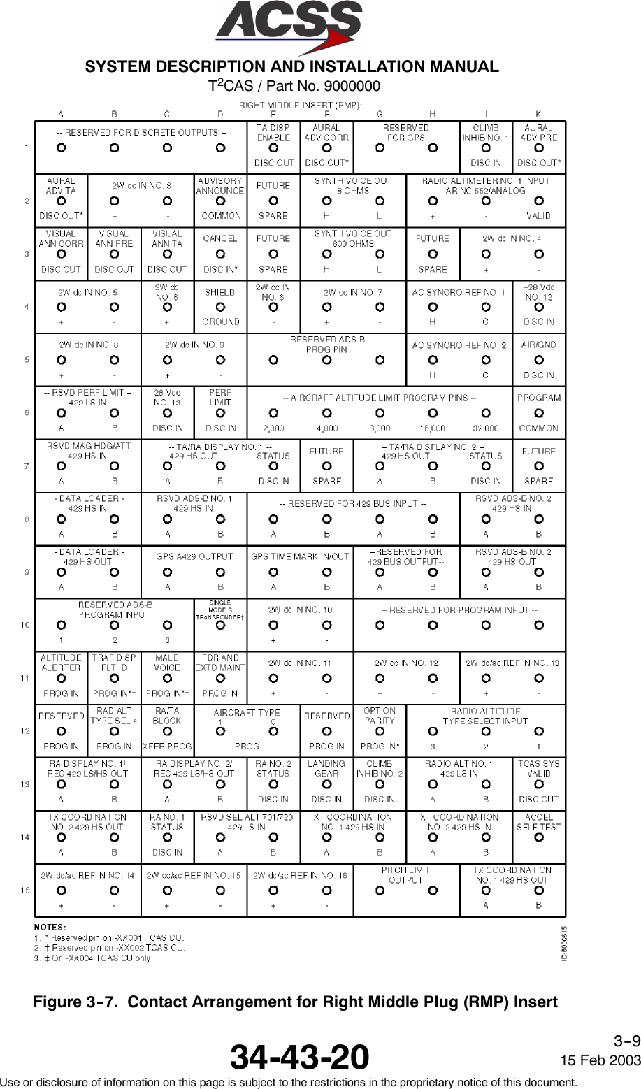
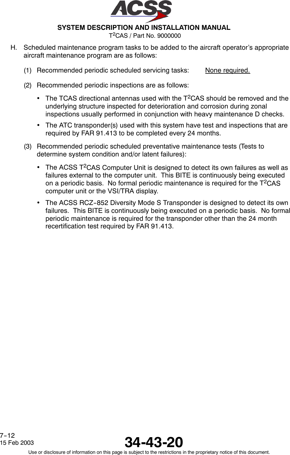
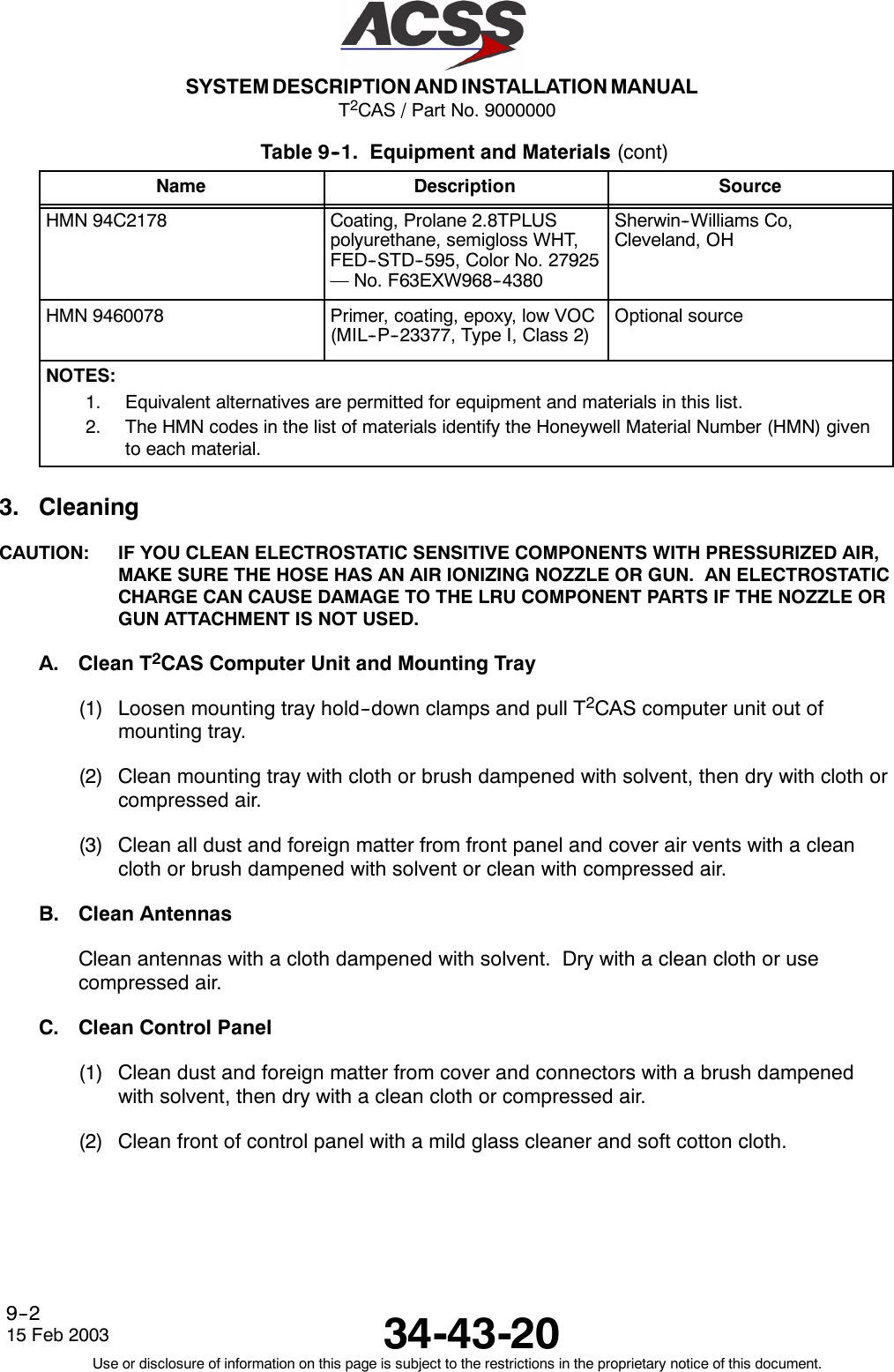
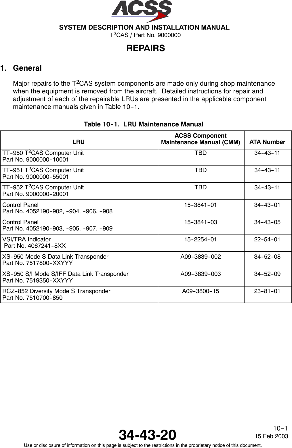
![T2CAS / Part No. 9000000SYSTEM DESCRIPTION AND INSTALLATION MANUAL34-43-20 15 Feb 2003Use or disclosure of information on this page is subject to the restrictions in the proprietary notice of this document.4--3Table 4--1. TT--950/951/952 T2CAS Computer Unit Interface Description (cont)Connector PinDesignation Functional DescriptionRMP--2E Spare PinRMP--2F, 2G 8 Ohm Audio Output: (RMP--2F [HI], RMP--2G [LO])This is a synthesized voice output supplied by the T2CAS computer unit. Its level isprogrammable up to 8 Watts into an 8 Ohm speaker. All aural traffic and resolutionadvisories are announced over this output. See RBP--7A for audio level programming.RMP--2H, 2J Radio Altimeter No. 1 ARINC 552/Analog Input: (RMP--2H [HI], RMP--2J [LO])Normal aircraft configurations include either two digital or two analog radio altimetersources. The T2CAS computer unit attempts to establish which type is present in order toobtain data from one of the two available sources. TCAS first checks the radio altimeterNo. 1 valid flag at RMP--2K. If No. 1 is not valid then No. 2 valid is checked at RBP--3C.If neither are valid then TCAS checks digital source No. 1 for valid data on the ARINC429 bus at RMP--13H and RMP--13J. If none of the above are valid then the TCASchecks the digital source No. 2 for valid data on the ARINC 429 bus at RBP--3D andRBP--3E. This process is repeated until a valid flag or data is detected.Until a valid source is found, the TCAS function inhibits all surveillance, CAS, and TA/RAdisplay functions, records failures in maintenance memory, and sets the TCAS systemstatus discrete output at RMP--13K to invalid. The TCAS function uses radio altitude toinhibit advisories and aural annunciation when in close proximity to the ground. Thisanalog input No. 1, as well as analog input No. 2, can accept data as a dc voltage fromseveral types of radio altimeters. The type of radio altimeter is selected using theprogram pins RMP--12B and RMP--12H thru RMP--12K.RMP--2K Radio Altimeter No. 1 Valid Input (PO)See RMP--2H. A valid condition is greater than +18.5 Vdc. An invalid is open circuit.RMP--3A Corrective Visual Advisory Discrete Output (NO)The visual advisory discrete outputs are ground/open type discretes (Note 3) used tooperate the annunciator lights on the displays. This output is activated whenever acorrective aural advisory is issued. The output remains active for the duration of theadvisory unless cancelled by the cancel discrete at RMP--3D. Only one visual advisory isactive at a time. The active state is ground and the inactive state is open.RMP--3B Preventive Visual Advisory Discrete Output (NO)Same as RMP--3A, except this discrete is activated whenever a preventative auraladvisory is issued.RMP--3C Traffic Visual Advisory Discrete Output (NO)Same as RMP--3A, except this discrete is active during a traffic advisory.RMP--3D Cancel Discrete Input (NO)This input discrete provides a means of canceling aural and visual alerts. It should beconnected to a cancel button (momentary ground type), if used. Groundprox/Windshearhas priority over the cancel button. Open is the inactive state and a momentary ground(less than 50 Ohms) produces the active state, canceling any active aural or visual alert.](https://usermanual.wiki/ACSS-an-L-3-Communications-and-Thales/TT-950.User-Manual-Part-2/User-Guide-302828-Page-44.png)
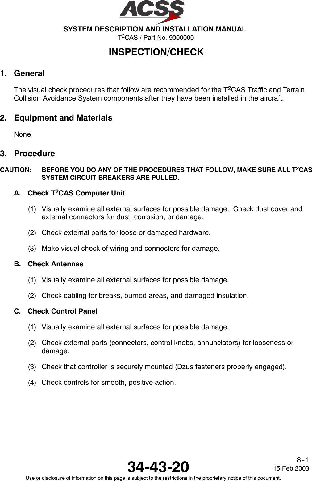
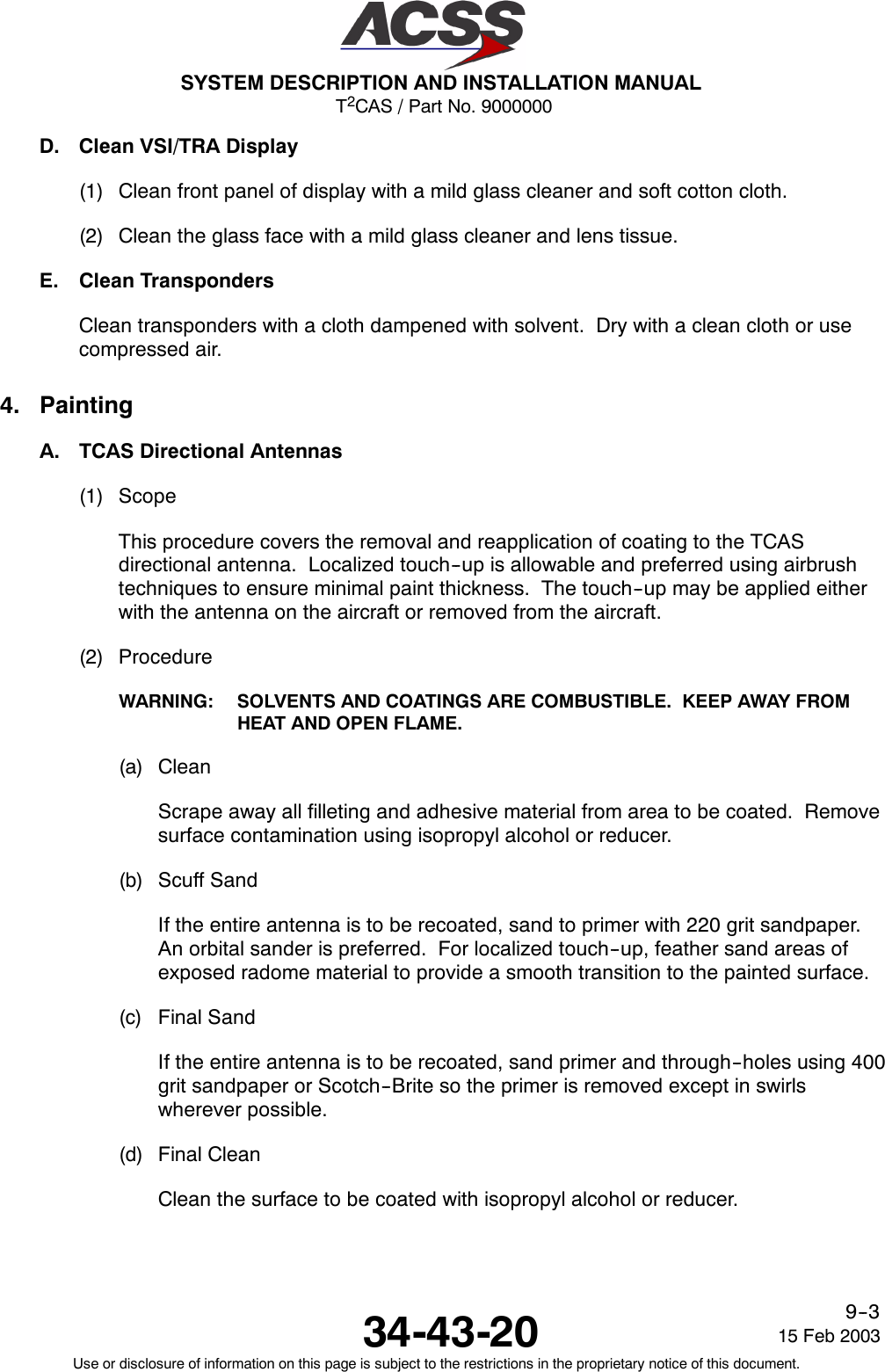
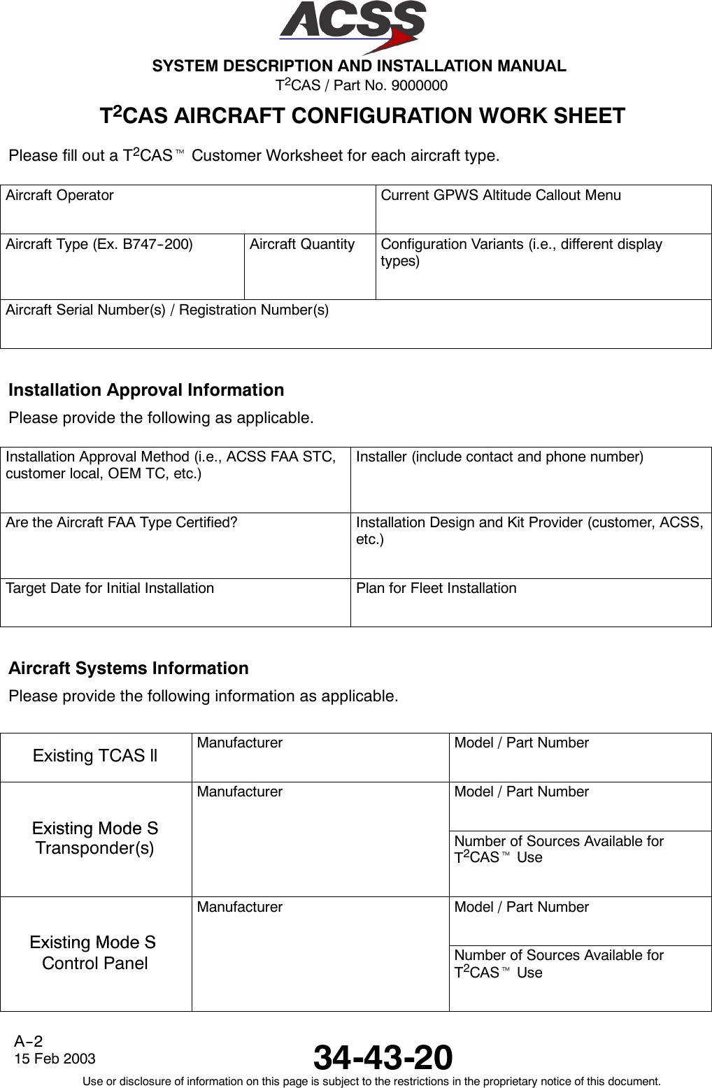
![T2CAS / Part No. 9000000SYSTEM DESCRIPTION AND INSTALLATION MANUAL34-43-2015 Feb 2003Use or disclosure of information on this page is subject to the restrictions in the proprietary notice of this document.4--4Table 4--1. TT--950/951/952 T2CAS Computer Unit Interface Description (cont)Connector PinDesignation Functional DescriptionRMP--3E Spare PinRMP--3F, 3G 600 Ohm Audio Output: [RMP--3F (HI), RMP--3G (LO)]This is a synthesized voice output supplied by the T2CAS computer unit. Its level isprogrammable up to 80 milliwatts into a 600 Ohm audio distribution system. All auraltraffic and resolution advisories are annunciated over this output. See RBP--7A for audiolevel programming.RMP--3H Spare PinRMP--3J Reserved for TAWS/RWS use.RMP--3K Reserved for TAWS/RWS use.RMP--4A Reserved for TAWS/RWS use.RMP--4B Reserved for TAWS/RWS use.RMP--4C Reserved for TAWS/RWS use.RMP--4D TCAS Installed Discrete Output (Ground)Indicates to external systems that a TCAS Computer is installed.RMP--4E Reserved for TAWS/RWS use.RMP--4F Reserved for TAWS/RWS use.RMP--4G Reserved for TAWS/RWS use.RMP--4H Reserved for TAWS/RWS use.RMP--4J Reserved for TAWS/RWS use.RMP--4K Reserved for TAWS/RWS use.](https://usermanual.wiki/ACSS-an-L-3-Communications-and-Thales/TT-950.User-Manual-Part-2/User-Guide-302828-Page-45.png)
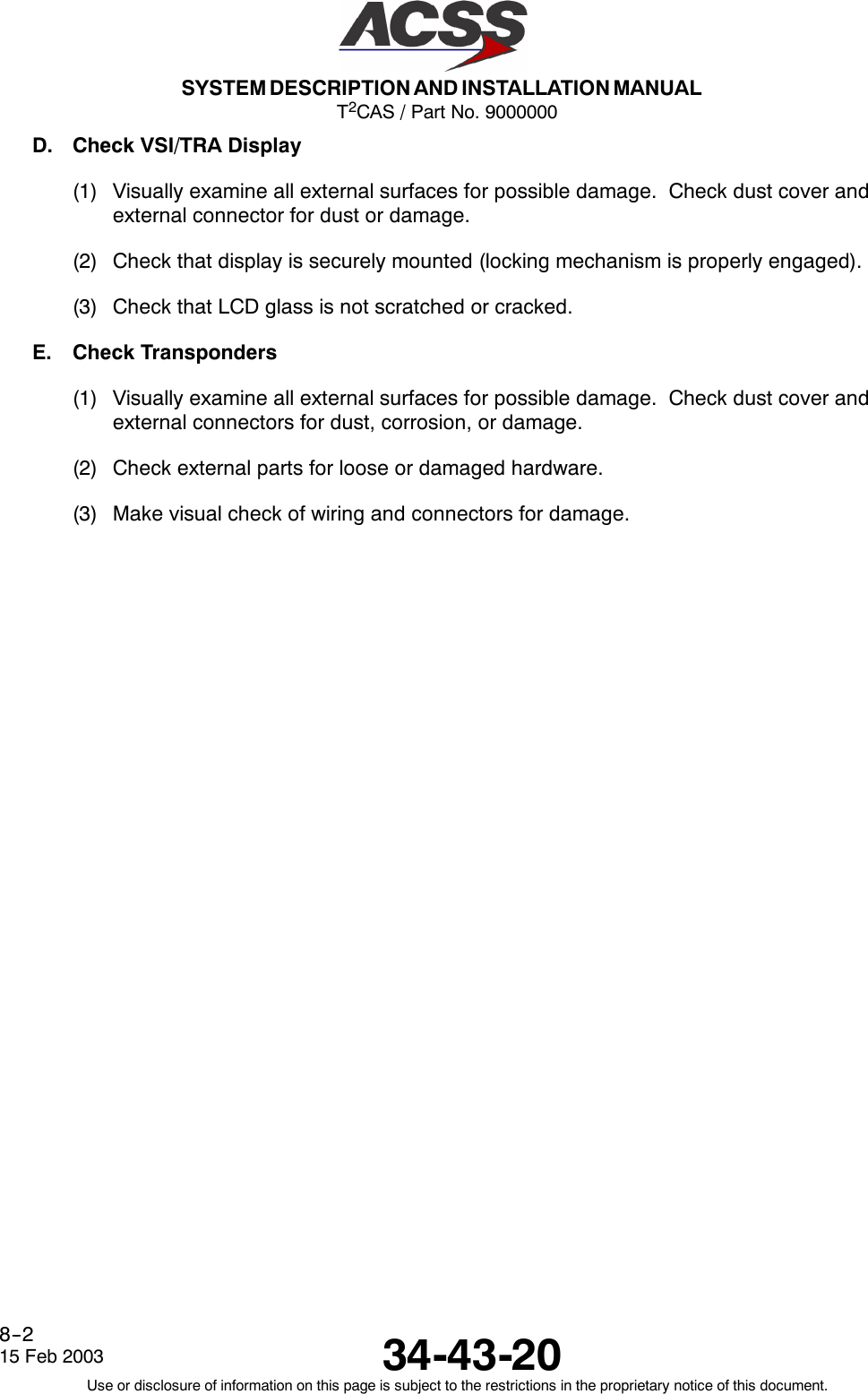
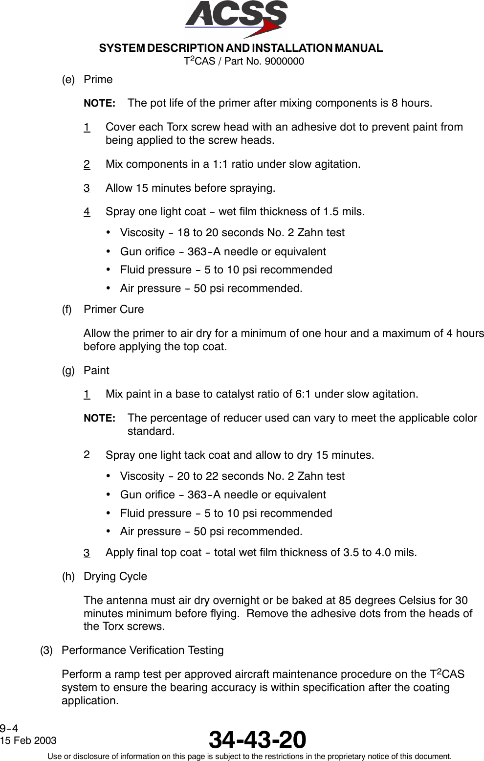
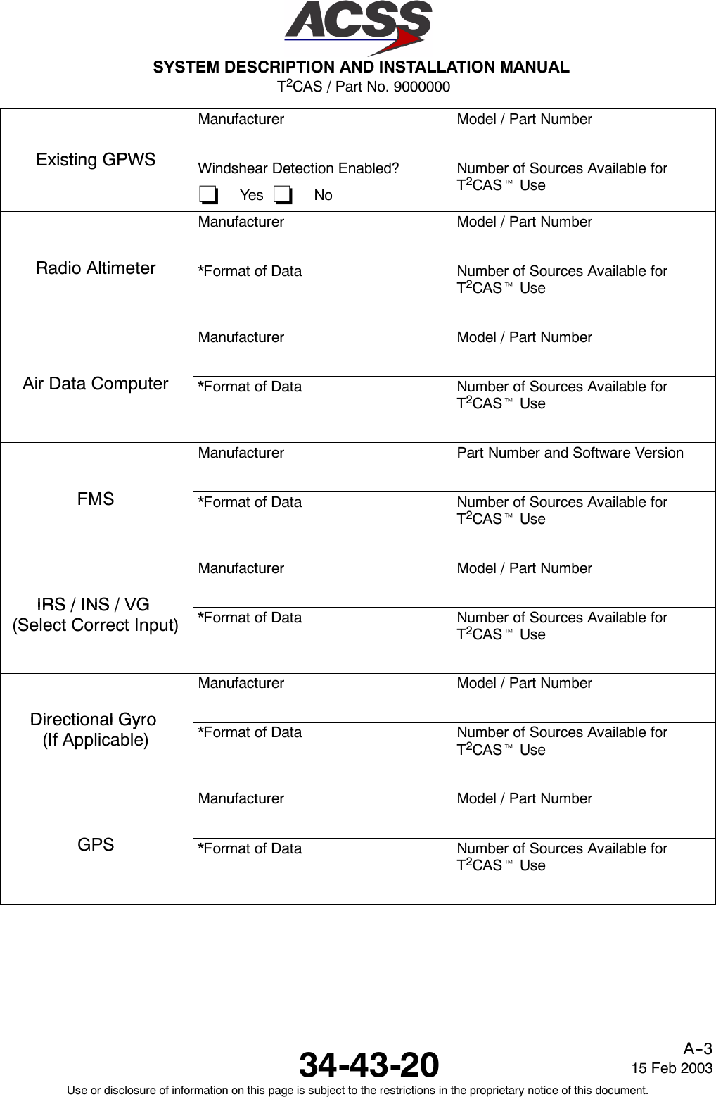
![T2CAS / Part No. 9000000SYSTEM DESCRIPTION AND INSTALLATION MANUAL34-43-20 15 Feb 2003Use or disclosure of information on this page is subject to the restrictions in the proprietary notice of this document.4--5Table 4--1. TT--950/951/952 T2CAS Computer Unit Interface Description (cont)Connector PinDesignation Functional DescriptionRMP--5A Reserved for TAWS/RWS use.RMP--5B Reserved for TAWS/RWS use.RMP--5C Reserved for TAWS/RWS use.RMP--5D Reserved for TAWS/RWS use.RMP--5E ADS--B Program Input (Intruder File Enable).RMP--5F ADS--B Program Input (GP Bus Enable).RMP--5G ADS--B Program Input (Reserved)RMP--5H Reserved for TAWS/RWS use.RMP--5J Reserved for TAWS/RWS use.RMP--5K Air Ground Discrete Input (NO): (Weight--On--Wheels)This ground/open type discrete input (Note 1) to the T2CAS computer unit indicates thestatus of the Air/Ground or Weight--On--Wheels (WOW) switch. TCAS filters this input tomake sure it remains in a steady state a minimum of 4 seconds before an Air/Groundtransition is recorded. An open indicates the aircraft is airborne and a ground indicatesthe aircraft is on the ground.Inputs should be diode isolated from each other.RMP--6A, 6B ARINC 429 Performance Limit Input: [RMP--6A (A), RMP--6B (B)]This Low Speed ARINC 429 (12.5 Kbits/s) input is provided for future applications toreceive climb rate performance limit information from an external device such as a FlightManagement Computer.RMP--6C Reserved for TAWS/RWS use.RMP--6D Performance Limit Discrete Input (NO)This input provides the T2CAS computer unit with an input from the Flight ManagementComputer (or equivalent) which indicates when the aircraft cannot achieve a 1500 FPMclimb rate. When this input is ground, the climb rate is not limited and no action isneeded by the T2CAS computer unit. When this input is open, the climb rate is limitedwhen the aircraft is above the value set by the altitude limit program pins (RMP--6E thruRMP--6J).](https://usermanual.wiki/ACSS-an-L-3-Communications-and-Thales/TT-950.User-Manual-Part-2/User-Guide-302828-Page-46.png)
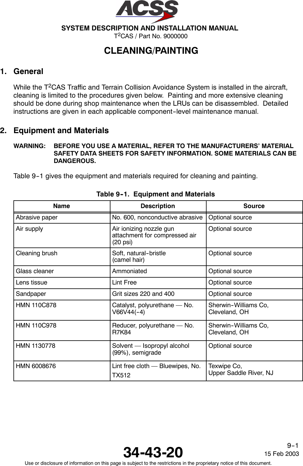
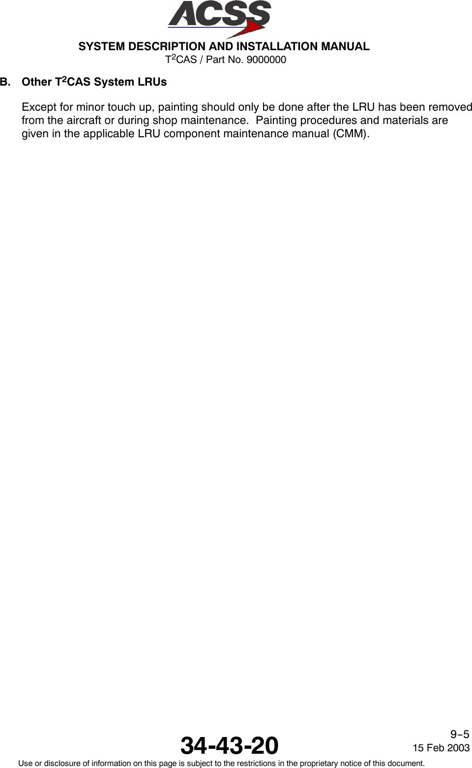
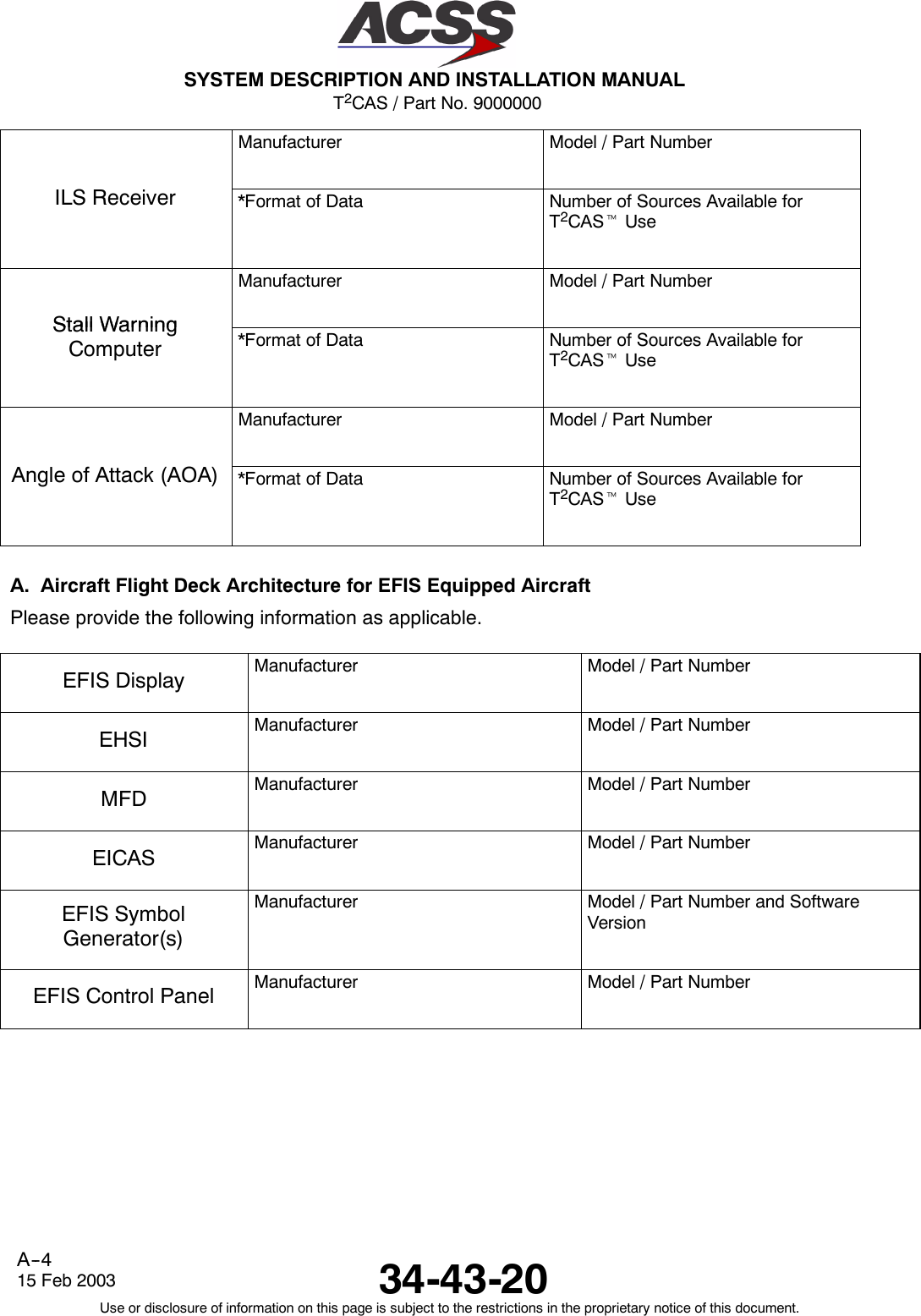
![T2CAS / Part No. 9000000SYSTEM DESCRIPTION AND INSTALLATION MANUAL34-43-2015 Feb 2003Use or disclosure of information on this page is subject to the restrictions in the proprietary notice of this document.4--6Table 4--1. TT--950/951/952 T2CAS Computer Unit Interface Description (cont)Connector PinDesignation Functional DescriptionRMP--6E 2000 FT Altitude Limit Program Pin (NO)This pin, along with pins RMP--6F thru RMP--6J, select the “can’t climb” altitude in2,000--foot increments up to 62,000 feet. This is the altitude the aircraft is not able toachieve a 0.25 G vertical acceleration to a 1500 FPM climb rate for an altitude gain of 750feet above a certain altitude under all circumstances. The “can’t climb” altitude isselected by connecting jumper wires from altitude limit program pins to the programcommon pin (RMP--6K).RMP--6F 4000 FT Altitude Limit Program Pin (NO)See RMP--6E.RMP--6G 8000 FT Altitude Limit Program Pin (NO)See RMP--6E.RMP--6H 16000 FT Altitude Limit Program Pin (NO)See RMP--6E.RMP--6J 32000 FT Altitude Limit Program Pin (NO)See RMP--6E.RMP--6K Program CommonSee RMP--6E.RMP--7A, 7B ARINC 429 Magnetic Heading/Attitude Input: [RMP--7A (A), RMP--7B (B)]Reserved for future useRMP--7C, 7D ARINC 429 TA/RA Display No. 1 Output: [RMP--7C (A), RMP--7D (B)]This is one of two ARINC 429 high speed (100 kbits/s) bus outputs that supplies data tothe TA/RA display such as a VSI/TRA or EFIS. The other output (TA/RA Display No. 2) isat RMP--7G and --7H. The TA/RA Display No. 1 outputs are also connected to the front(PDL) connector, which is used to supply display information to maintenance displays.See J1--33 and J1--34.RMP--7E TA/RA Display No. 1 Status Discrete Input (NO)Two display status ground/open discrete inputs (Note 1) are provided by the T2CAScomputer unit at RMP--7E (TA/RA Display No. 1) and RMP--7J (TA/RA Display No. 2). Aground on either of these inputs is interpreted by TCAS to mean the display associatedwith that input is operating normally and is capable of displaying the TA/RA information,and that its data bus is active. An open indicates the inability of the display to presentadvisories or indicates its data bus is inactive.RMP--7F Spare PinRMP--7G, 7H ARINC 429 TA/RA Display No. 2 Output: [RMP--7G (A), RMP--7H (B)]See RMP--7C and --7D.RMP--7J TA/RA Display No. 2 Status Discrete Input (NO)See RMP--7E.RMP--7K Spare Pin](https://usermanual.wiki/ACSS-an-L-3-Communications-and-Thales/TT-950.User-Manual-Part-2/User-Guide-302828-Page-47.png)
![T2CAS / Part No. 9000000SYSTEM DESCRIPTION AND INSTALLATION MANUAL34-43-20 15 Feb 2003Use or disclosure of information on this page is subject to the restrictions in the proprietary notice of this document.4--7Table 4--1. TT--950/951/952 T2CAS Computer Unit Interface Description (cont)Connector PinDesignation Functional DescriptionRMP--8A, 8B ARINC 429 Data Loader Input: [RMP--8A (A), RMP--8B (B)]These pins are used when the T2CAS computer unit is communicating with an ARINC603 or 615 airborne data loader (ADL) through the rear ARINC 600 connector. The dataloader programs the program memory in the T2CAS computer unit per the data loaderfunction specified. The ADL and portable data loader (PDL) Low Speed ARINC 429inputs (12.5 kbits/s) have separate receiver busses to allow for simultaneous connectionof the ADL and PDL.These pins are also connected to the front (PDL) connector on the front of the unit. SeeJ1--1 and J1--2.RMP--8C,8D ARINC 429 ADS--B No. 1 Input: [RMP--8C (A), RMP--8D (B)]TA/RA Display Control A429 Input #1RMP--8E, 8F ARINC 429 Bus Input: [RMP--8E (A), RMP--8F (B)]General Purpose A429 Input #1RMP--8G, 8H ARINC 429 Bus Input: [RMP--8G (A), RMP--8H (B)]TA/RA Display Control A429 Input #2RMP--8J, 8K ARINC 429 ADS--B No. 2 Input: [RMP--8J (A), RMP--8K (B)]TAWS to TCAS A429 Output (A)RMP--9A, 9B ARINC 429 Data Loader Output: [RMP--9A (A), RMP--9B (B)]These pins are used when the T2CAS computer unit is communicating with an ARINC603 or 615 airborne data loader (ADL) through the rear ARINC 600 connector. Thisconnection is used to transmit data to the ADL during data loading operations.These pins are also connected to the front (PDL) connector on the front of the unit. SeeJ1--8 and J1--9.RMP--9C, 9D Reserved for GPS use.RMP--9E, 9F Reserved for TAWS/GPS use.RMP--9G, 9H ARINC 429 Bus Output: [RMP--9G (A), RMP--9H (B)]CD General Purpose A429 Output #1RMP--9J, 9K ARINC 429 ADS--B No. 2 Output: [RMP--9J (A), RMP--9K (B)]CD General Purpose A429 Output #2](https://usermanual.wiki/ACSS-an-L-3-Communications-and-Thales/TT-950.User-Manual-Part-2/User-Guide-302828-Page-48.png)
![T2CAS / Part No. 9000000SYSTEM DESCRIPTION AND INSTALLATION MANUAL34-43-20 15 Feb 2003Use or disclosure of information on this page is subject to the restrictions in the proprietary notice of this document.4--9Table 4--1. TT--950/951/952 T2CAS Computer Unit Interface Description (cont)RMP--12B Radio Altimeter Type Select Program Input No. 4 (NO)The T2CAS computer unit uses radio altitude to inhibit advisories and aural annunciationwhen in close proximity to the ground. This analog input No. 1, as well as analog inputNo. 2 can accept data as a dc voltage from several types of radio altimeters. Programpin RMP--12B is used, along with program pins RMP--12H, --12J, and --12K, to identify thetype of analog radio altimeter installed.For T2CAS CU ARINC 552, Collins BCA, AHV--6, NR--AS--10A, LPIA, APN--232 CARAand metric type radio altimeters can be selected. The program pin inputs useground/open logic levels. All unassigned program pin combinations are invalid andshould not be selected. Pin RMP--6K can be used to supply a ground.Program PinRMP--12K RMP--12J RMP--12H RMP--12B Altimeter TypeOpen Open Open Open ARINC 552/552AOpen Open Open Ground Collins BCAOpen Open Ground Open Metric Altimeter No. 1Open Open Ground Ground UnassignedOpen Ground Open Open Metric Altimeter No. 2Open Ground Open Ground UnassignedOpen Ground Ground Open Metric Altimeter No. 3Open Ground Ground Ground UnassignedGround Open Open Open Metric Altimeter No. 4Ground Open Open Ground UnassignedGround Open Ground Open Military AHV6 (Linear)Ground Open Ground Ground Military AHV6 (Log)Ground Ground Open Open Military NR--AS--10A (Alternate)Ground Ground Open Ground Military APN--232 CARAGround Ground Ground Open Military LPIAGround Ground Ground Ground Military NR--AS--10A (Curve Fit)The Radio Altitude sources listed are defined by the following:ARINC 552/552A-- 2 0 < H < 480 feet: Voltage = [ 0.02 x (H + 20) ] Vdc480 < H < 2500 feet: Voltage = [ 10 x ( 1 + ln((H + 20)/500)) ] VdcWere H = Radio Altitude in feet.Maximum Voltage output is 26.2 Vdc at any height above 2500 feet.Collins BCA-- 2 0 < H < 500 feet: Voltage = [ 0.02 x (H + 20) ] Vdc500 < H < 2500 feet: Voltage = [ 10.4 + 0.003 x (H -- 500) ] VdcWere H = Radio Altitude in feet.Maximum Voltage output is 26.2 Vdc at any heightabove 2500 feet.AHV 6 Linear0.0 to 25.0 Vdc: H = 200V -- 20Were H = Radio Altitude in feet and V = Voltage in Volts dc.](https://usermanual.wiki/ACSS-an-L-3-Communications-and-Thales/TT-950.User-Manual-Part-2/User-Guide-302828-Page-50.png)
![T2CAS / Part No. 9000000SYSTEM DESCRIPTION AND INSTALLATION MANUAL34-43-2015 Feb 2003Use or disclosure of information on this page is subject to the restrictions in the proprietary notice of this document.4--12Table 4--1. TT--950/951/952 T2CAS Computer Unit Interface Description (cont)Connector PinDesignation Functional DescriptionRMP--13A, 13B RA Display No. 1/ARINC 429 Data Recorder Output: [RMP--13A (A), RMP--13B (B)]These ARINC 429 outputs are configured to output either RA information or for use as anARINC 429 data recorder function. The output is configured by program pin RMP--11D.When RMP--11D is open (standard configuration), the bus is configured for low--speed(12.5 kbits/s) ARINC 429 operation and RA information is output according to the formatspecified for the RA display bus in ARINC 735. When RMP--11D is grounded, the bus isconfigured for high--speed (100 kbits/s) ARINC 429 operation and the output supplies TAand RA information to a 429 data recorder.RMP--13C, 13D RA Display No. 2/ARINC 429 Data Recorder Output: [RMP--13C (A), RMP--13D (B)]See RMP--13A.RMP--13E RA Display No. 2 Status Discrete Input (NO)This ground/open discrete input (Note 1) provides the functional status of RA Display No.2. A ground on this pin indicates a valid display. If this discrete is not used by the RADisplay, connect to aircraft ground to prevent RA DISPLAY No. 2 fail message duringself--test.RMP--13F Landing Gear Discrete Input (NO)The T2CAS computer monitors this discrete that indicates the landing gear position.Landing Gear is a Ground/Open type discrete (Note 1) were an open indicates the gear isretracted (gear is up) and a ground indicates the gear is extended (gear is down).RMP--13G Climb Inhibit No. 2 Discrete Input (NO)See RMP--1J.RMP--13H, 13J Radio Altimeter No. 1 Input: [RMP--13H (A), RMP--13J (B)]This input is provided for Low Speed ARINC 429 (12.5 Kbits/s) altitude inputs from anARINC 707 digital radio altimeter. Radio altitude data is used for computation ofsensitivity level, inhibit descend advisories, and inhibit aural annunciation when in closeproximity to the ground. Also see RMP--2H.RMP--13K TCAS System Valid Discrete Output (NO)This ground/open type discrete output (Note 3) indicates the health status of the T2CAScomputer unit to other avionics systems that monitor TCAS system status. This output isused in retrofit installations where instrumentation needs to monitor TCAS status and thestatus is not available across an A429 bus. A ground at this pin indicates normal TCASoperation. An open indicates a TCAS fault.RMP--14A, 14B ARINC 429 TX Coordination Bus No. 2 Output: [RMP--14A (A), RMP--14B (B)]This differential pair output is a high speed ARINC 429 bus (100k bits/second nominal),that transmits data from the TCAS computer unit to the No. 2 Mode S Transponder.The labels on this bus are as follows: 273, 274, 275.](https://usermanual.wiki/ACSS-an-L-3-Communications-and-Thales/TT-950.User-Manual-Part-2/User-Guide-302828-Page-53.png)
![T2CAS / Part No. 9000000SYSTEM DESCRIPTION AND INSTALLATION MANUAL34-43-20 15 Feb 2003Use or disclosure of information on this page is subject to the restrictions in the proprietary notice of this document.4--13Table 4--1. TT--950/951/952 T2CAS Computer Unit Interface Description (cont)Connector PinDesignation Functional DescriptionRMP--14C RA Display No. 1 Status Discrete Input (NO)This ground/open discrete input (Note 1) provides the functional status of RA Display No.1. A ground on this pin indicates a valid display. If this discrete is not used by the RAdisplay, connect to aircraft ground to prevent RA DISPLAY No. 1 fail message duringself--test.RMP--14D, 14E Selected Altitude701/720 ARINC 429 Bus InputReserved for future use.RMP--14F, 14G ARINC 429 XT Coordination No. 1 Input: [RMP--14F (A), RMP--14G (B)]This differential pair input is a high speed ARINC 429 bus (100k bits/second nominal),that receives data from the No. 1 Mode S Transponder.The labels on this bus are as follows: 013, 015, 016, 203, 271, 272, 273, 274, 275, 276,277, 350.RMP--14H, 14J ARINC 429 XT Coordination No. 2 Input: [RMP--14H (A), RMP--14J (B)]This differential pair input is a high speed ARINC 429 bus (100k bits/second nominal),that receives data from the No. 2 Mode S Transponder.The labels on this bus are as follows: 013, 015, 016, 203, 271, 272, 273, 274, 275, 276,277, 350.RMP--14K Reserved for TAWS/RWS use.RMP--15AtoRMP--15HReserved for TAWS/RWS use.RMP--15J, 15K ARINC 429 TX Coordination No. 1 Output: [RMP--15J (A), RMP--15K (B)]This differential pair output is a high speed ARINC 429 bus (100k bits/second nominal),that transmits data from the T2CAS computer unit to the No. 1 Mode S Transponder.The labels on this bus are as follows: 273, 274, 275.](https://usermanual.wiki/ACSS-an-L-3-Communications-and-Thales/TT-950.User-Manual-Part-2/User-Guide-302828-Page-54.png)
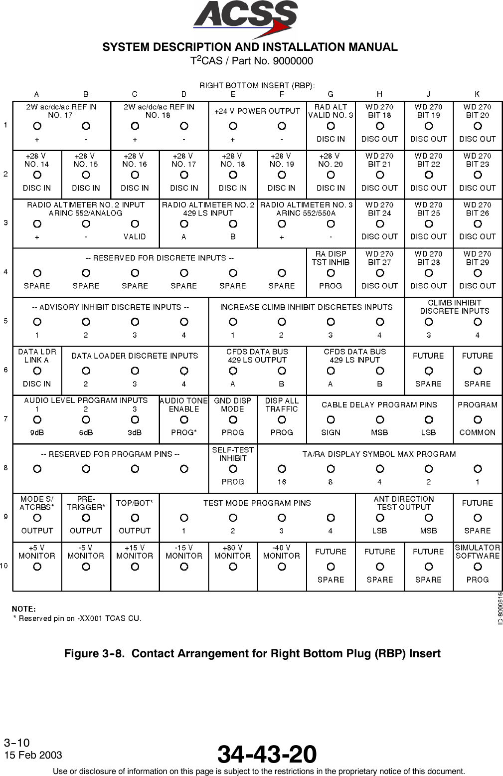
![T2CAS / Part No. 9000000SYSTEM DESCRIPTION AND INSTALLATION MANUAL34-43-2015 Feb 2003Use or disclosure of information on this page is subject to the restrictions in the proprietary notice of this document.4--14Table 4--1. TT--950/951/952 T2CAS Computer Unit Interface Description (cont)Connector PinDesignation Functional DescriptionT2CAS Computer Unit Right Bottom Plug (RBP)RBP--1AThruRBP--1G Reserved for TAWS/RWS use.RBP--1H RA Data Word 270 Bit 18 Discrete OutputThis discrete output provides RA information to the ARINC 573 flight recorder. Theoutput goes to the “ground” state each time its associated bit within the advisory field ofthe RA output words changes from a “zero” condition to a “one” condition. The outputremains in the “ground” state for as long as the associated RA bit remains non--zero.This output is read by the flight recorder as either a series or shunt output.NOTE: The discrete is pulled up to +28 Vdc in the “open” state.RBP--1J RA Data Word 270 Bit 19 Discrete OutputSee RBP--1H.RBP--1K RA Data Word 270 Bit 20 Discrete OutputSee RBP--1H.RBP--2AThruRBP--2G Reserved for TAWS/RWS use.RBP--2H RA Data Word 270 Bit 21 Discrete OutputSee RBP--1H.RBP--2J RA Data Word 270 Bit 22 Discrete OutputSee RBP--1H.RBP--2K RA Data Word 270 Bit 23 Discrete OutputSee RBP--1H.RBP--3A, 3B Radio Altimeter No. 2 ARINC 552/Analog Input: [RBP--3A (HI), RBP--3B (LO)]See RMP--2H and --2J.RBP--3C Radio Altimeter No. 2 Valid Discrete Input (PO)See RMP--2H. Valid condition is greater than +18.5 Vdc. Invalid is open.RBP--3D, 3E Radio Altimeter No. 2 Input: [RBP--3D (A), RBP--3E (B)]See RMP--13H. Also see RMP--2H.RBP--3F,RBP--3GReserved for TAWS/RWS use.RBP--3H RA Data Word 270 Bit 24 Discrete OutputSee RBP--1H.RBP--3J RA Data Word 270 Bit 25 Discrete OutputSee RBP--1H.](https://usermanual.wiki/ACSS-an-L-3-Communications-and-Thales/TT-950.User-Manual-Part-2/User-Guide-302828-Page-55.png)
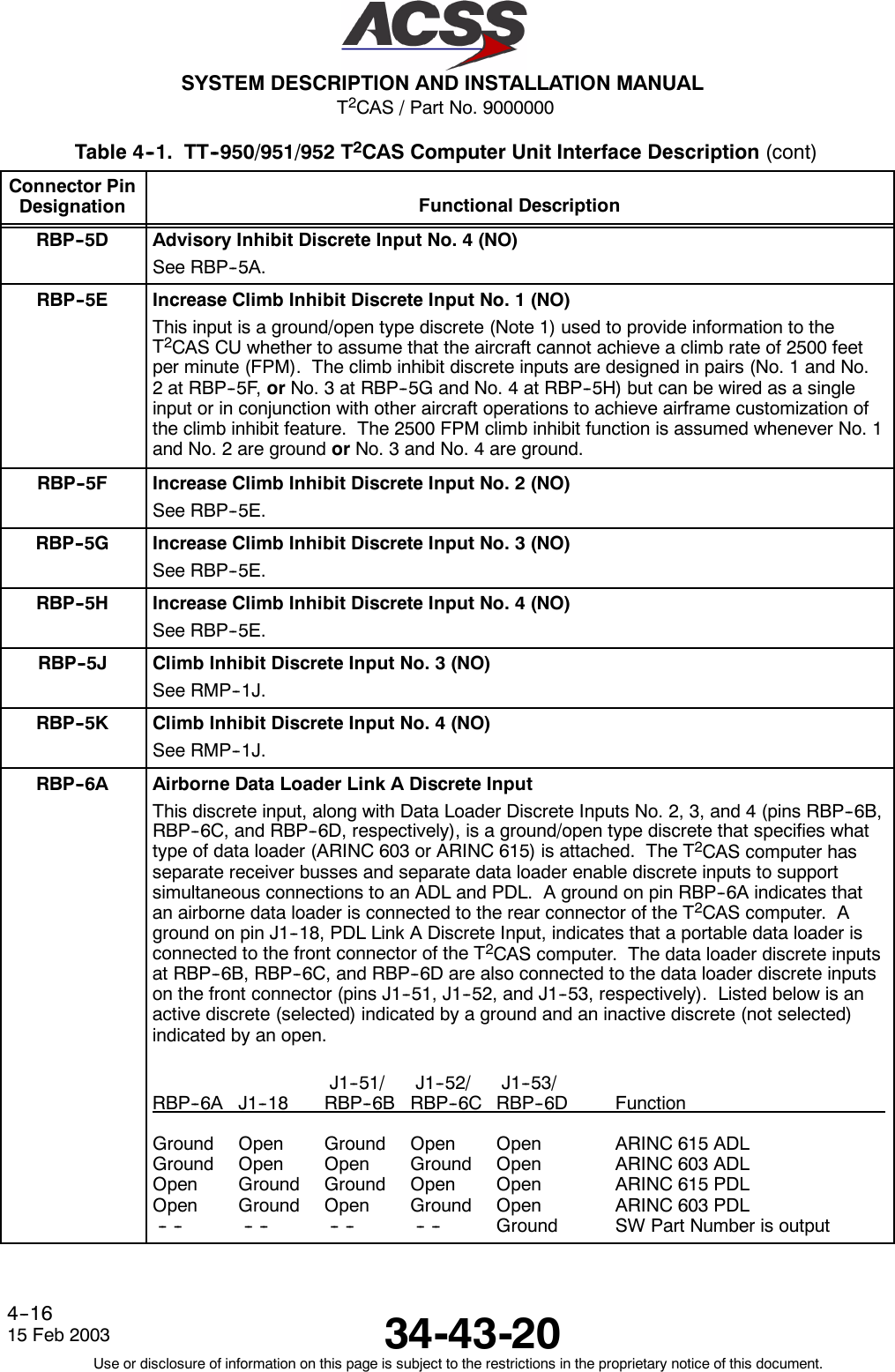
![T2CAS / Part No. 9000000SYSTEM DESCRIPTION AND INSTALLATION MANUAL34-43-20 15 Feb 2003Use or disclosure of information on this page is subject to the restrictions in the proprietary notice of this document.4--17Table 4--1. TT--950/951/952 T2CAS Computer Unit Interface Description (cont)Connector PinDesignation Functional DescriptionRBP--6B Data Loader Discrete Input No. 2See RBP--6A.RBP--6C Data Loader Discrete Input No. 3See RBP--6A.RBP--6D Data Loader Discrete Input No. 4See RBP--6A.RBP--6E, 6F ARINC 429 CFDS Output: [RBP--6E (A), RBP--6F (B)]This differential pair output is a low speed ARINC 429 bus (12.5k bits/second nominal),that transmits data to an onboard maintenance computer or a central fault display system.RBP--6G, 6H ARINC 429 CFDS Input: [RBP--6G (A), RBP--6H (B)]This differential pair input is a low speed ARINC 429 bus (12.5k bits/second nominal), thatreceives data from an onboard maintenance computer or a central fault display system.RBP--6J Spare PinRBP--6K Spare PinRBP--7A Audio Level Program Pin No. 1 (NO)Two synthesized voice outputs with programmable output levels are provided by theT2CAS computer unit. The output at RMP--2F and --2G supply high level (up to 8 Watts)audio signals to an 8 Ohm speaker. The second output at RMP--3F and --3G supply lowlevel (up to 80 milliwatts) audio signals to a 600 Ohm audio distribution system. All auraltraffic and resolution advisories can be annunciated over these outputs unless cancelledby a Cancel Discrete (RMP--3D).Listed below are the audio level program pin configurations and the resulting outputlevels:Program PinRBP--7A RBP--7B RBP--7C Low Level Output High Level Output(MSB) (LSB) dBm mW dBm WOpen Open Open 16 40 6 4Open Open Ground 13 20 3 2Open Ground Open 10 10 0 1Open Ground Ground 7 5 --3 0.5Ground Open Open 4 2.5 --6 0.25Ground Open Ground 1 1.25 --9 0.125Ground Ground Open --2 0.625 --12 0.0625Ground Ground Ground 19 80 9 8RBP--7B Audio Level Program Pin No. 2 (NO)See RBP--7A.RBP--7C Audio Level Program Pin No. 3 (NO)See RBP--7A.](https://usermanual.wiki/ACSS-an-L-3-Communications-and-Thales/TT-950.User-Manual-Part-2/User-Guide-302828-Page-58.png)
![T2CAS / Part No. 9000000SYSTEM DESCRIPTION AND INSTALLATION MANUAL34-43-2015 Feb 2003Use or disclosure of information on this page is subject to the restrictions in the proprietary notice of this document.4--22Table 4--1. TT--950/951/952 T2CAS Computer Unit Interface Description (cont)Connector PinDesignation Functional DescriptionLBP--10 +28 Vdc Power Input (HI)This pin along with the T2CAS computer unit +28 Vdc Power Return line (LBP--3) providethe +28 Vdc power requirements for the T2CAS computer unit.Wiring requirement is a standard #18 AWG.NOTE: The T2CAS TT--950/--952 computer operates with either 115 V ac, 400 Hz, or+28 Vdc input power and the TT--951 computer operates on +28 Vdc inputpower only. On the TT--950/--952 computers, if +28 Vdc is used, the powershould be connected through a 10 Amp circuit breaker, and the pins for the 115Vac input should be left unconnected.LBP--11 Chassis GroundConnect to aircraft frame. The T2CAS Chassis and signal ground pins should use thesame AWG as the power connections (See LBP--1 and LBP--10).LBP--12 Mutual Suppression Pulse Bus InputThe T2CAS computer unit joins the mutual suppression bus daisy chained through TCASand other RF transmitting equipment on board the aircraft. The TCAS function receivessuppression pulses from other LRUs on this bus, which is used to suppress the TCASreceivers during such transmissions. This prevents the TCAS function from interpretingthese transmissions as valid replies from an intruder aircraft. When not suppressed, theTCAS function transmits its own suppression pulses on the same bus in order tosuppress the receivers in other L--band systems on the aircraft. The L--Band suppressioncoax must be RG142, RG400, or equivalent coaxial cable which meets the operationalcharacteristics required by ARINC 735A.LBP--13 GPS Antenna Port (Active on TT--952 and reserved for TT--950 and TT--951)T2CAS unit TT--952 uses this pin for the GPS Antenna port -- RF input from the GPSantenna and +12 Vdc output to power the active amplifier GPS antenna.The minimum coax loss between the GPS antenna’s output and the T2CAS computer’sGPS input port is equal to the maximum preamplifier gain minus 29 dB. The maximumcoax loss between the GPS antenna’s output and the T2CAS computer’s GPS input portis equal to the minimum preamplifier gain minus 12.5 dB.The Interface descriptions that follow are for the 53--pin Data Loader connector J1 mounted on thefront panel of the T2CAS computer unit. These descriptions are used to make up the cable that isused to interface between the T2CAS computer unit and an ARINC 615 Portable Data Loader (PDL),a RS--232 PC Serial Port, a RS--422 Flight Data Recorder, or an ARINC 429 Maintenance Display.J1--1, 2 ARINC 429 PDL Bus Input: [J1--1 (A), J1--2 (B)]This differential pair input is a high--speed ARINC 429 bus (100k bits/second nominal)that is used to input data from the data loader to the TCAS computer unit. The standardsfor this interface are defined in ARINC 615 Airborne Computer High Speed Data Loader.These pins should be connected to pins 1 and 2 of the PDL cable interface.J1--3,J1--4Spare Pins](https://usermanual.wiki/ACSS-an-L-3-Communications-and-Thales/TT-950.User-Manual-Part-2/User-Guide-302828-Page-63.png)
![T2CAS / Part No. 9000000SYSTEM DESCRIPTION AND INSTALLATION MANUAL34-43-20 15 Feb 2003Use or disclosure of information on this page is subject to the restrictions in the proprietary notice of this document.4--23Table 4--1. TT--950/951/952 T2CAS Computer Unit Interface Description (cont)Connector PinDesignation Functional DescriptionJ1--5 Output Bus ShieldsThe shields from the output bus (J1--8, 9) should be connected to this pin.J1--6,J1--7A615A Data Loader Ethernet Output [J1--6 (TD+), J1--7 (TD--)]TAWS Ethernet 10 Base--T.J1--8, 9 ARINC 429 Data Loader/PDL Recorder Bus Output: [J1--8 (A), J1--9 (B)]This differential pair output is a high--speed ARINC 429 bus (100K bits/second nominal)that is used to output data from the T2CAS computer unit to the data loader. Thestandards for this interface are defined in ARINC 615 Airborne Computer High SpeedData Loader.These pins should be connected to pins 8 and 9 of the PDL cable interface.J1--10, 11 RS--422 Recorder External Clock Input: [J1--10 (+), J1--11 (--)]These two pins provide external clocking from an RS--422 Flight Data Recorder forTCAS.J1--12, 13 RS--422 Recorder Reply Input: [J1--12 (+), J1--13 (--)]These two pins provide communication from a RS--422 Flight Data Recorder for TCAS.J1--14 RS--422 Recorder 125 kHz/ External Program PinThis pin is used to designate internal or external recorder clock operation for TCAS. Aground on this pin selects external recorder clock operation. An open selects 125k Hzinternal recorder clock operation.J1--15 RS--422 Recorder Disable Program PinThis program pin is used to enable or disable the RS--422 Data Recorder function forTCAS. The program pin is activated externally by the Flight Data Recorder. Logic is asfollows:Ground = RS--422 Recorder disabled; Open = RS--422 Recorder enabledJ1--16 Input Bus ShieldsThe shields from the input bus (J1--1, 2) should be connected to this pin.J1--17 Spare PinJ1--18 PDL Link A Discrete InputThis is a ground/open discrete (Note 1) from an portable ARINC 615 or ARINC 603 dataloader which indicates, to the T2CAS computer unit, that a data loader is connected. Aground indicates a data loader is connected. This pin is used by the TCAS, TAWS/RWSand GPS.J1--19 PDL Link B CommonConnect this pin to pin 19 of the PDL cable interface.](https://usermanual.wiki/ACSS-an-L-3-Communications-and-Thales/TT-950.User-Manual-Part-2/User-Guide-302828-Page-64.png)
![T2CAS / Part No. 9000000SYSTEM DESCRIPTION AND INSTALLATION MANUAL34-43-2015 Feb 2003Use or disclosure of information on this page is subject to the restrictions in the proprietary notice of this document.4--24Table 4--1. TT--950/951/952 T2CAS Computer Unit Interface Description (cont)Connector PinDesignation Functional DescriptionJ1--20, 22 115 Vac Power Output: [J1--20 (H), J1--22 (C)]These power output pins provide the 115 Vac operating power for the data loader.The 115 Vac (H) and 115 Vac (C) interconnect wires should be shielded or twisted andshielded with an insulating jacket over the shield. The shield should be connected tochassis ground (J1--21).J1--21 Chassis GroundConnect 115 Vac power shields to this pin.J1--23 A615A Dataloader Ethernet Input (RD+)TAWS Ethernet 10--base--T read inputJ1--24ThruJ1--28Spare PinsJ1--29, 30 RS--422 Recorder Data Output: [J1--29 (+), J1--30 (--)]The RS--422 Flight Data Recorder data is output on these pins.J1--31, 32 RS--422 Recorder Clock Output: [J1--31 (+), J1--32 (--)]The RS--422 Flight Data Recorder internal 125k Hz internal clock is output on these pins.J1--33,34 ARINC 429 TA/RA Display No. 1 Output: [J1--33 (A), J1--34 (B)]This bus can be used to connect to a maintenance display. These pins are alsoconnected to the ARINC 600 connector on the rear of the unit (RMP--7C and --7D).J1--35,J1--36Spare PinsJ1--37, 38 28 V dc Power Output: [J1--37 (HI), J1--38 (LO)]These power output pins provide the +28 Vdc operating power for the data loader. Thesepins are used only if the data loader operates from a +28 Vdc source.J1--39 A615A Dataloader Ethernet Input (RD--)TAWS Ethernet 10--base--T read inputJ1--40 T2CAS RS--232 Data InputThis input is used by the TAWS, TCAS and GPS function to receive RS--232 data from aportable maintenance terminal.J1--41 T2CAS RS--232 Data OutputThis output is used by the TAWS, TCAS and GPS function to transmit RS--232 data to aportable maintenance terminal.J1--42 TCAS RS--232 Data InputThis input is used by the TCAS function to receive RS--232 data from a portablemaintenance terminal.J1--43 TCAS RS--232 Data OutputThis output is used by the TCAS function to transmit RS--232 data to a portablemaintenance terminal.](https://usermanual.wiki/ACSS-an-L-3-Communications-and-Thales/TT-950.User-Manual-Part-2/User-Guide-302828-Page-65.png)
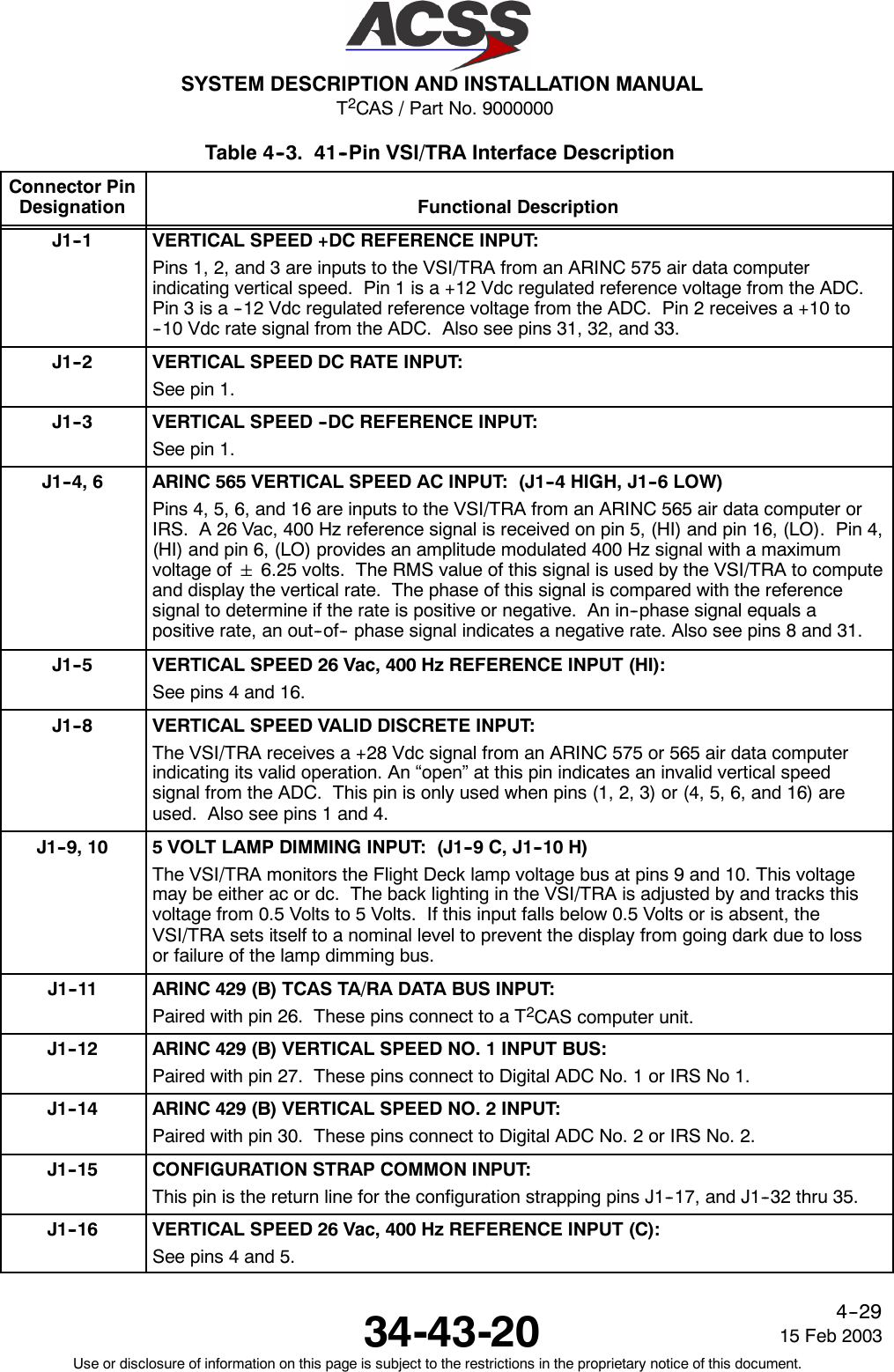
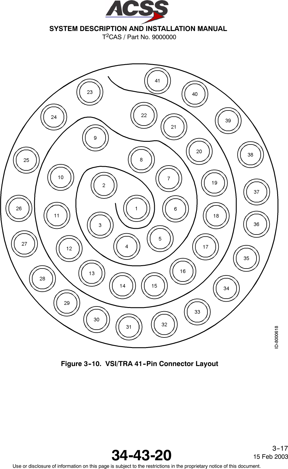
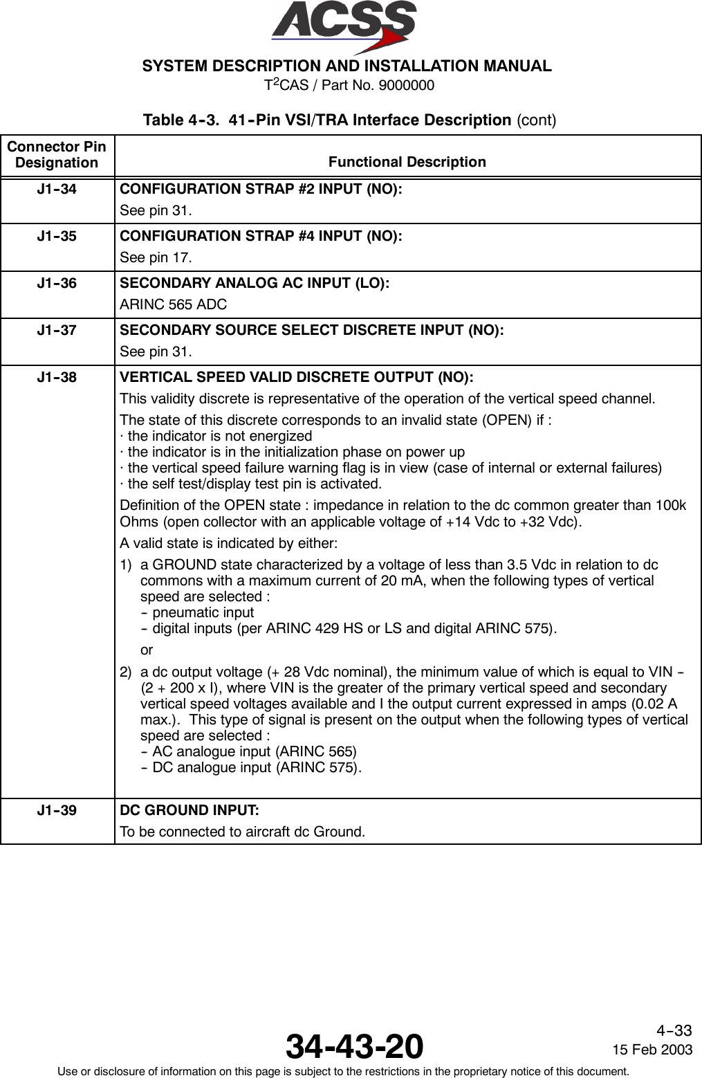
![T2CAS / Part No. 9000000SYSTEM DESCRIPTION AND INSTALLATION MANUAL34-43-2015 Feb 2003Use or disclosure of information on this page is subject to the restrictions in the proprietary notice of this document.4--30Table 4--3. 41--Pin VSI/TRA Interface Description (cont)Connector PinDesignation Functional DescriptionJ1--17 CONFIGURATION STRAP #3 INPUT (NO):Pin 17 is used in conjunction with pin 35 to select the indicator operating mode as follows:The following applies: O = Open, G = Ground.Pin 35 17 Indicator Operating ModeG G Test (shop level)G O VSI onlyO G RA VSI onlyO O TA/RA VSIJ1--18 SECONDARY VERT SPEED VALIDITY INPUT (+28 Vdc):The VSI/TRA receives a +28 Vdc signal from an ARINC 575 or 565 air data computerindicating its valid operation. An “open” at this pin indicates an invalid vertical speedsignal from the ADC. This pin is only used when pins (1, 2, 3) or (4, 5, 6, and 16) areused.J1--19, 20 VERT SPEED BOOTSTRAP AC OUT: (J1--19 [HIGH], J1--20 [LO])This output repeats the ARINC 565 input signals (26 V 400 Hz reference and signal)available on the primary input when this input has been selected :-- 26 V 400 Hz referenceThe voltage available on the output (26 Vac Bootstrap ref. output) is the same as thatavailable on the 26 Vac 400 Hz reference (hot) of the ARINC 565 primary input, thecommon reference being the cold of the 26 Vac primary ref. input.-- Output signal (vertical speed bootstrap AC output) available on two wires (HI and LO).J1--22 CHASSIS GROUND INPUT:Connected to aircraft frame. Also used to connect ARINC cable shields to the chassis.J1--23 115 Vac, 400 HZ POWER INPUT (COMMON):See pin 40. Connect to aircraft AC ground.J1--24, 25 REMOTE LIGHT SENSOR INPUT: (J1--24 LOW, J1--25 HIGH)This input at pins 24 and 25 provides a means of controlling the VSI/TRA back lighting viaa remote light sensor already present in some aircraft (Douglas and Boeing). TheVSI/TRA has its own built--in sensor and therefore a remote light sensor need not beused in all installations. Program the VSI/TRA for a remote light sensor, as describedunder pin 34.J1--26 ARINC 429 (A) TCAS TA/RA DATA INPUT:Traffic and Resolution Advisory data is supplied to the VSI/TRA from the T2CAScomputer unit via this high speed ARINC 429 data bus. Paired with pin 11.](https://usermanual.wiki/ACSS-an-L-3-Communications-and-Thales/TT-950.User-Manual-Part-2/User-Guide-302828-Page-71.png)
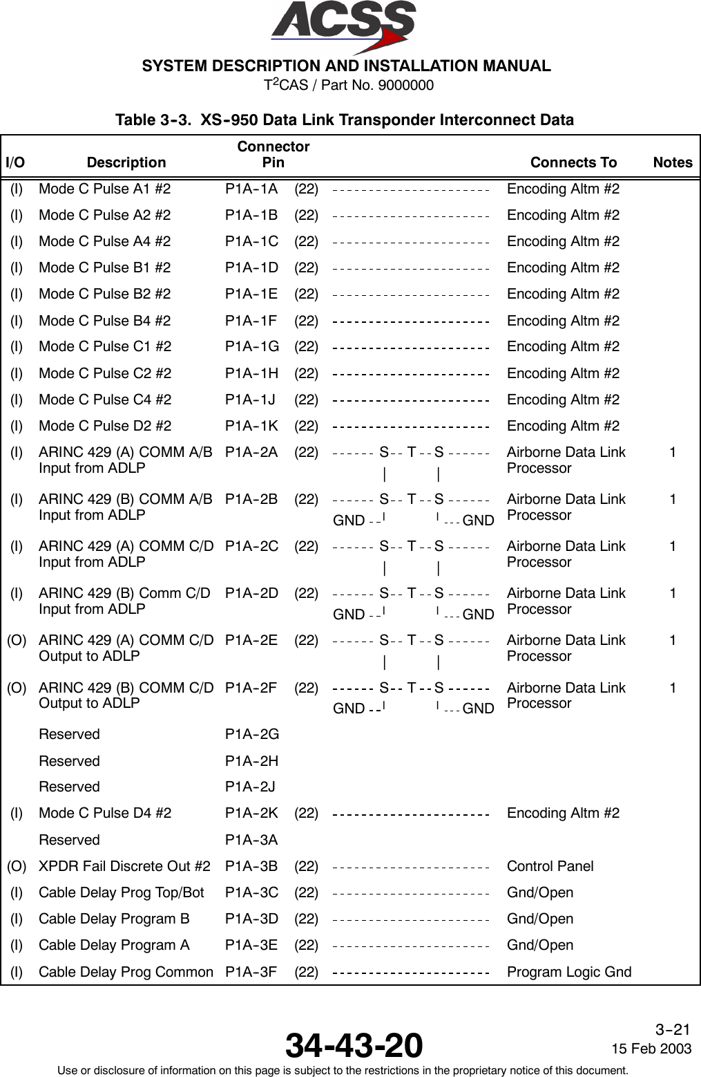
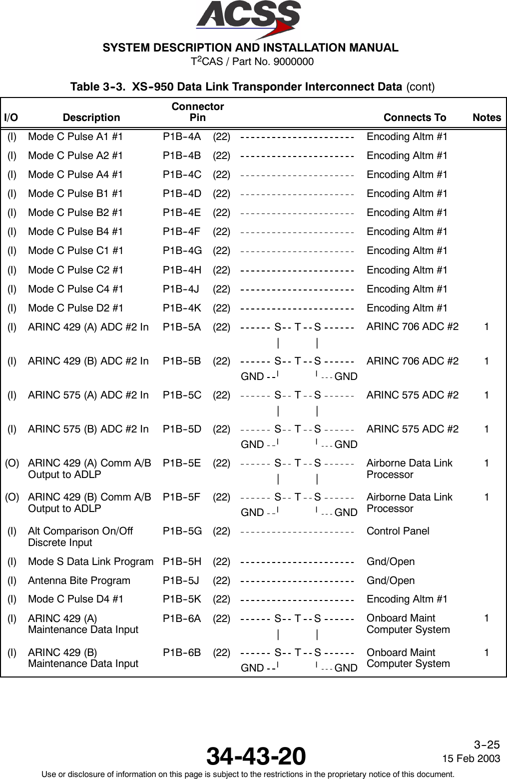
![T2CAS / Part No. 9000000SYSTEM DESCRIPTION AND INSTALLATION MANUAL34-43-20 15 Feb 2003Use or disclosure of information on this page is subject to the restrictions in the proprietary notice of this document.4--35Table 4--4. XS--950 Data Link Transponder Interface DescriptionConnector PinDesignation Functional DescriptionP1A--1A THRUP1A--1K, ANDP1A--2KENCODING ALTIMETER #2 INPUTS:These Mode C pulse discrete inputs allow for altitude inputs from an encoding altimeterthat contains a discrete 11 wire interface. The standards for this interface are defined inARINC Characteristic 572, “Air Traffic Control Transponder”. The inputs use ground/openlogic levels.NOTE: Two encoding altimeters are required if the transponder is used with TCAS.P1A--2A, 2B ARINC 429 ADLP TO COMM A/B BUS INPUT: [P1A--2A (A), P1A--2B (B)]Four high speed ARINC 429 busses (100k bits/second nominal) are provided forinterfacing to a Mode S Airborne Data Link Processor (ADLP). The COMM A/B input andoutput busses are used for the transfer of standard length messages to and from theADLP. The COMM C/D input and output busses are used for the transfer of extendedlength messages (ELM) to and from the ADLP. The standard for this interface is definedin ARINC Characteristic 718, “Air Control Transponder (ATCRBS/Mode S)”.P1A--2C, 2D ARINC 429 ADLP TO COMM C/D BUS INPUT: [P1A--2C (A), P1A--2D (B)]See pins P1A--2A, 2BP1A--2E, 2F ARINC 429 COMM C/D TO ADLP BUS OUTPUT: [P1A--2E (A), P1A--2F (B)]See pins P1A--2A, 2BP1A--3B XPDR FAIL DISCRETE OUTPUT #2:This discrete output is set to annunciate an internal transponder failure or the Mode Saddress is illegal (All 0’s or 1’s). A ground logic threshold (<+3.0 Vdc) is output when thetransponder is operating normally, and an open logic threshold (resistance >100k Ohmsto unit ground) when a failure has occurred. The output is capable of sinking 200 mA ofcurrent. Connect this pin to the Control Panel XPDR FAIL #2 input.P1A--3C,P1A--3D,P1A--3E,P1A--3FCABLE DELAY PROGRAM INPUTS:The Cable Delay Program Inputs are used to compensate for the difference inpropagation delays in the transponder due to antenna transmission line length differencesbetween the top and bottom antennas. The inputs use ground/open logic levels. TheCable Delay Program Common (pin P1A--3F) can be used to supply a ground.Program Pin Differential TransponderP1A--3C P1A--3D P1A--3E Delay AdjustmentOpen Open Open 0--50 nsec No ChangeOpen Open Ground 51--150 nsec Add Delay to Top ChannelOpen Ground Open 151--250 nsec Add Delay to Top ChannelOpen Ground Ground 251--350 nsec Add Delay to Top ChannelGround Open Open 0--50 nsec No ChangeGround Open Ground 51--150 nsec Add Delay to Bottom ChannelGround Ground Open 151--250 nsec Add Delay to Bottom ChannelGround Ground Ground 251--350 nsec Add Delay to Bottom ChannelThe differential delay column is the difference in the round trip cable delay between thetop and bottom antenna cables. The differential delay can be calculated as follows:[Top length in feet -- Bottom length in feet] X [Characteristic Delay (nsec/foot)] X 2.](https://usermanual.wiki/ACSS-an-L-3-Communications-and-Thales/TT-950.User-Manual-Part-2/User-Guide-302828-Page-76.png)
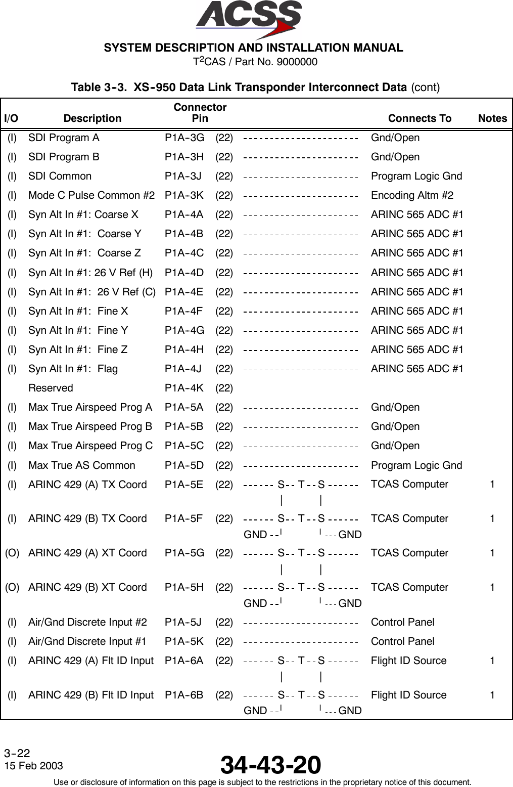
![T2CAS / Part No. 9000000SYSTEM DESCRIPTION AND INSTALLATION MANUAL34-43-2015 Feb 2003Use or disclosure of information on this page is subject to the restrictions in the proprietary notice of this document.4--36Table 4--4. XS--950 Data Link Transponder Interface Description (cont)Connector PinDesignation Functional DescriptionP1A--3G,P1A--3H,P1A--3JSDI PROGRAM INPUTS:The SDI program inputs are used to identify the system number in the installation. Theinputs use ground/open logic levels. The SDI Common (pin P1A--3J) can be used tosupply a ground.Program PinP1A--3G P1A--3H DefinitionOpen Open Not Applicable (SDI = 00)Open Ground LRU System #1 (SDI = 01)Ground Open LRU System #2 (SDI = 10)Ground Ground LRU System #3 (SDI = 11)P1A--4ATHRUP1A--4JARINC 565 ANALOG AIR DATA COMPUTER #1 INPUTS:These input pins allow for altitude information from an Analog Synchro Altitude Interfaceto be connected to the transponder. The standards for this interface are defined inARINC 565, “Subsonic Air Data System”.P1A--5A,P1A--5B,P1A--5C,P1A--5DMAXIMUM TRUE AIRSPEED PROGRAM INPUTS:The Maximum True Airspeed inputs are used for strapping the maximum cruise airspeedcapability of the aircraft. The inputs use ground/open logic levels. The Max TrueAirspeed Common (pin P1A--5D) can be used to supply a ground.Program PinP1A--5A P1A--5B P1A--5C DefinitionOpen Open Open No Maximum Airspeed AvailableGround Open Open Maximum Airspeed ≤75 KnotsOpen Ground Open Maximum Airspeed >75 and ≤150 KnotsGround Ground Open Maximum Airspeed >150 and ≤300 KnotsOpen Open Ground Maximum Airspeed >300 and ≤600 KnotsGround Open Ground Maximum Airspeed >600 and ≤1200 KnotsOpen Ground Ground Maximum Airspeed >1200 KnotsGround Ground Ground Not AssignedP1A--5E, 5F ARINC 429 TX COORDINATION BUS INPUT: (P1A--5E [A], P1A--5F [B])Two high speed ARINC 429 busses (100k bits/second nominal) are provided to interfacebetween the transponder and a TCAS computer unit. The standards for this interface aredefined in ARINC Characteristic 735A, “Traffic Alert and Collision Avoidance System”.P1A--5G, 5H ARINC 429 XT COORDINATION BUS OUTPUT: (P1A--5G [A], P1A--5H [B])See pins P1A--5E, 5F.](https://usermanual.wiki/ACSS-an-L-3-Communications-and-Thales/TT-950.User-Manual-Part-2/User-Guide-302828-Page-77.png)
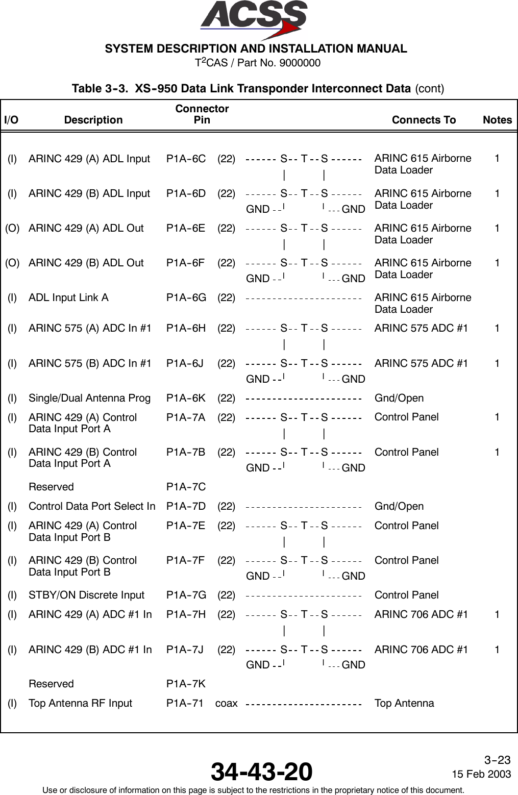
![T2CAS / Part No. 9000000SYSTEM DESCRIPTION AND INSTALLATION MANUAL34-43-20 15 Feb 2003Use or disclosure of information on this page is subject to the restrictions in the proprietary notice of this document.4--37Table 4--4. XS--950 Data Link Transponder Interface Description (cont)Connector PinDesignation Functional DescriptionP1A--5J AIR / GROUND #2 DISCRETE INPUT:This pin and AIR / GROUND #1 Discrete Input (pin P1A--5K) provide a method for thetransponder to automatically determine the Air/Ground status of the aircraft. The status isused in replies to Mode S interrogations and to inhibit replies to certain types ofinterrogations. Both inputs use ground/open logic, where a Ground specifies an “On theGround” condition and an Open specifies an “In the Air” condition.When this pin is connected to the Air/Ground Relay (Squat Switch), the transponder willnot reply to ATCRBS, ATCRBS/Mode S All Call, or Mode S All Call when the input is setfor “On the Ground”. This input should be connected to the Air/Ground Relay for normaloperation.P1A--5K AIR / GROUND #1 DISCRETE INPUT:See pin P1A--5J.When this pin is connected to the Air/Ground Relay (Squat Switch), the transponderreplies to all types of interrogations irregardless of the state of the input. This input allowsthe transponder to reply during a ramp test.P1A--6A, 6B ARINC 429 FLIGHT IDENTIFICATION BUS INPUT: (P1A--6A [A], P1A--6B [B])This differential pair input is a low speed ARINC 429 bus (12.5k bits/second nominal) thataccepts a flight identification that is contained within four ARINC 429 data words (labels233, 234, 235 and 236).P1A--6C, 6D ARINC 615 AIRBORNE DATA LOADER BUS INPUT: (P1A--6C [A], P1A--6D [B])The Airborne Data Loader interface consists of two high speed ARINC 429 busses (100kbits/second nominal) and a ground/open logic discrete (pin P1A--6G). The interfaceallows for operational transponder software to be loaded into the unit through an onboarddata loader. The standards for this interface are defined in ARINC 615 “AirborneComputer High Speed Data Loader”.P1A--6E, 6F ARINC 615 AIRBORNE DATA LOADER BUS OUTPUT: (P1A--6E [A], P1A--6F [B])See pins P1A--6C, 6DP1A--6G ADL INPUT LINK A DISCRETE INPUT:See pins P1A--6C, 6DP1A--6H, 6J ARINC 575 AIR DATA COMPUTER #1 INPUT: (P1A--6H [A], P1A--6J [B])This differential pair input is a low speed ARINC 575 bus (12.5k bits/second nominal) thatcan be used to input altitude information from an ARINC 575 Air Data System. Thestandards for this interface are defined in ARINC Characteristic 575, “Subsonic Air DataSystem (Digital) DADS”.P1A--6K SINGLE / DUAL ANTENNA PROGRAM INPUT:This pin allows for installation of the transponder in a system with a single bottommounted antenna or dual top and bottom mounted antennas. The input usesground/open logic as follows:Ground = Single Bottom Mounted Antenna ConfigurationOpen = Diversity Antenna Configuration](https://usermanual.wiki/ACSS-an-L-3-Communications-and-Thales/TT-950.User-Manual-Part-2/User-Guide-302828-Page-78.png)
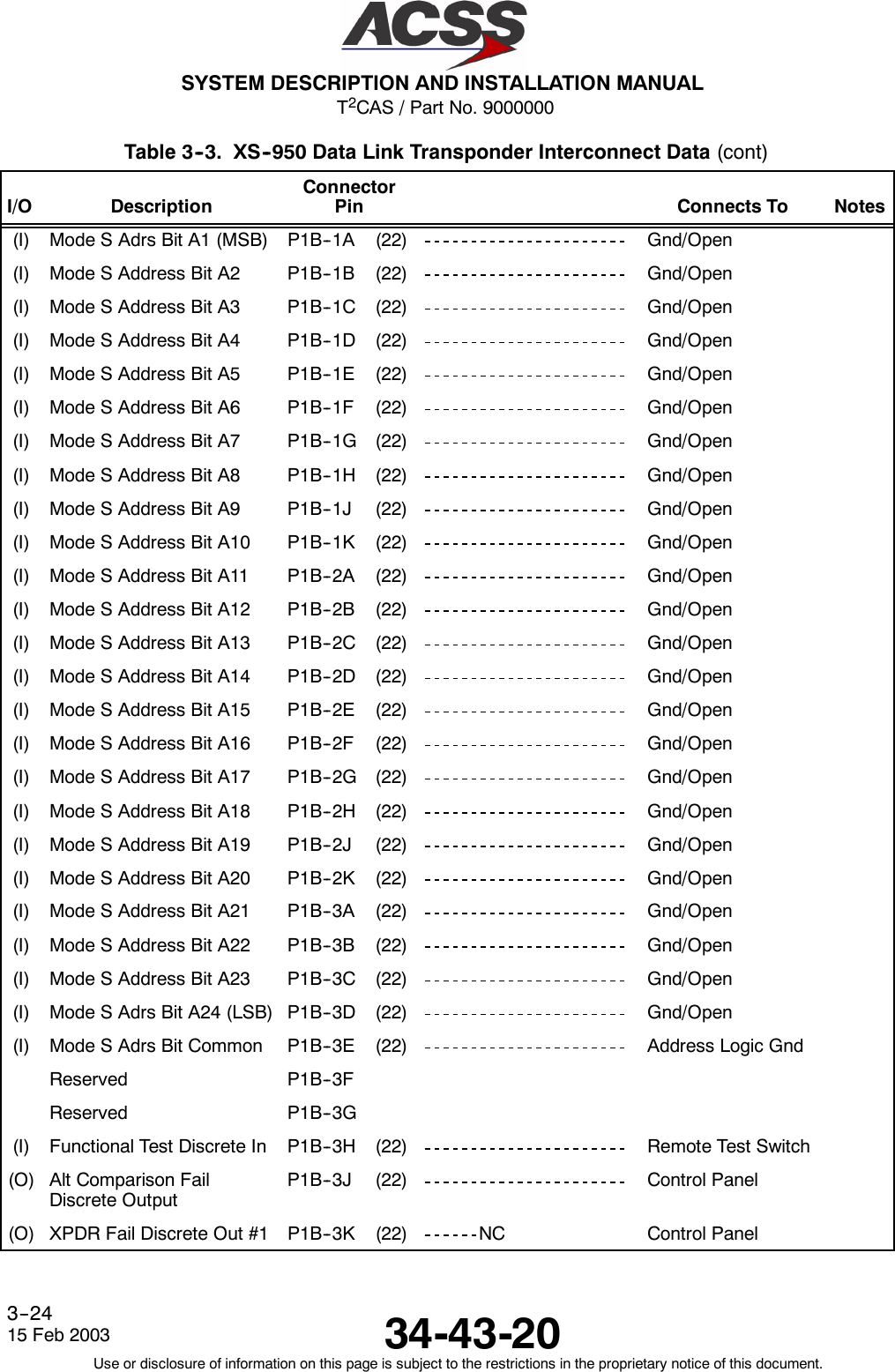
![T2CAS / Part No. 9000000SYSTEM DESCRIPTION AND INSTALLATION MANUAL34-43-2015 Feb 2003Use or disclosure of information on this page is subject to the restrictions in the proprietary notice of this document.4--38Table 4--4. XS--950 Data Link Transponder Interface Description (cont)Connector PinDesignation Functional DescriptionP1A--7A, 7B ARINC 429 CONTROL DATA PORT A BUS INPUT: (P1A--7A [A], P1A--7B [B])The control panel data can be input into the transponder on either of two low speedARINC 429 busses. (Ports A and B). The control data is contained in labels 013, 015,and 016. The port is selected by the CONTROL DATA PORT SELECT Discrete Input(pin PIA--7D).P1A--7D CONTROL DATA PORT SELECT INPUT:See pins P1A--7A, 7B.This discrete input is used to select which port is used to input control data to thetransponder. This input uses a ground/open logic as follows:Ground Specifies Port AOpen Specifies Port BP1A--7E, 7F ARINC 429 CONTROL DATA PORT B BUS INPUT: (P1A--7E [A], P1A--7F [B])See pins P1A--7A, 7B.P1A--7G STANDBY / ON DISCRETE INPUT:This discrete input is connected to the Control Panel STANDBY/ON output. The inputselects the active or standby status of the transponder. A ground causes the transponderto be in standby, and an open causes the transponder to be active.P1A--7H, 7J ARINC 429 ADC #1 BUS INPUT: (P1A--7H [A], P1A--7J [B])The altitude information for the transponder can be obtained from an ARINC 706 Air DataSystem through two low speed ARINC 429 data busses. The standards for this interfaceare defined in ARINC Characteristic 706, “Mark 5 Subsonic Air Data System”.This differential pair input is a low speed ARINC 429 bus that inputs uncorrected pressurealtitude (ARINC label 203) from an altitude source. Also see pins P1B--5A, 5B.P1A--71 TOP ANTENNA RF INPUT:RF input from top antenna.P1B--1ATHRUP1B--3EMODE S ADDRESS INPUTS:The Mode S Address is a unique 24--bit code assigned to each aircraft. Pins P1B--1Athru P1B--3E are used to program this 24--bit binary number. The inputs must be setaccording to this binary number representation. Each binary 1represents a Grounded pinand each binary 0represents an Open pin. Pin P1B--1A represents the most significantbit (MSB) of the binary number and pin P1B--3D represents the least significant bit (LSB)of the binary number.NOTE: An address of all 0’s or all 1’s is an illegal address, and can cause the aircraft tobe invisible to TCAS II equipped aircraft in flight. Never use an illegal addressfor an installed system.P1B--3H FUNCTIONAL TEST DISCRETE INPUT:This discrete input is used to put the transponder in a functional test mode. Thefunctional test that is performed by the transponder is equivalent to a test that is initiatedfrom the control panel. The input uses ground/open logic as follows:Ground = Initiate Functional TestOpen = Normal Operation](https://usermanual.wiki/ACSS-an-L-3-Communications-and-Thales/TT-950.User-Manual-Part-2/User-Guide-302828-Page-79.png)
![T2CAS / Part No. 9000000SYSTEM DESCRIPTION AND INSTALLATION MANUAL34-43-20 15 Feb 2003Use or disclosure of information on this page is subject to the restrictions in the proprietary notice of this document.4--39Table 4--4. XS--950 Data Link Transponder Interface Description (cont)Connector PinDesignation Functional DescriptionP1B--3J ALTITUDE COMPARISON FAIL DISCRETE OUTPUT:This discrete output annunciates a comparison failure in the altitude data for thetransponder if Gillham altitude data is selected. The output annunciates a failure if thetwo altitude sources are not within 500 feet.The output drives a ground logic threshold (voltage of less than +3.0 Vdc) when thealtitude is valid, and an open logic threshold (resistance is greater than 100k Ohms to unitground) when a failure has occurred. The output is capable of sinking 200 mA of current.P1B--3K XPDR FAIL DISCRETE OUTPUT #1:This discrete output is set to annunciate an internal transponder failure or that the Mode Saddress is illegal (All 0’s or 1’s). The output will source a voltage of greater than +5.0 Vdcat 100 mA of current when a failure has occurred, and an open circuit (resistance ofgreater than 100k Ohms to unit ground) when the transponder is operating normally. Theoutput contains diode isolation. Connect this pin to the Control Panel XPDR FAIL #1input.P1B--4A THRUP1B--4K, ANDP1B--5KENCODING ALTIMETER #1 INPUTS:First of two Encoding Altimeter interfaces. See pins P1A--1A thru 4K and P1A--2K.P1B--5A, 5B ARINC 429 AIR DATA COMPUTER #2 BUS INPUT: (P1B--5A [A], P1B--5B [B])Second ARINC 429 Air Data Computer bus input. See pins P1A--7H, 7J.P1B--5C, 5D ARINC 575 AIR DATA COMPUTER #2 BUS INPUT: (P1B--5C [A], P1B--5D [B])Second ARINC 575 Air Data Computer bus input. See pins P1A--6H, 6J.P1B--5E, 5F ARINC 429 COMM A/B TO ADLP BUS OUTPUT: (P1B--5E [A], P1B--5F [B])See pins P1A--2A, 2B.P1B--5G ALTITUDE COMPARISON ON / OFF DISCRETE INPUT:This discrete input is used to enable/disable the Altitude Comparison function. TheAltitude Comparison function is used only if a Gillham altitude source is selected. This pinuses a ground/open logic as follows:Ground = Altitude Comparison EnabledOpen = Altitude Comparison DisabledNOTE: If an altitude source other than Gillham is selected, the input has no function.P1B--5H MODE S DATA LINK PROGRAM INPUT:This program input specifies if the transponder is connected to an Airborne Data LinkProcessor (ADLP) Unit. The input uses ground/open logic as follows:Ground = ADLP is InstalledOpen = ADLP is not installedP1B--5J ANTENNA BITE PROGRAM INPUT:This program input specifies if the transponder is to perform a built--in test to the antennasubsystem. The transponder performs a continuity check of the antenna to make sure itis not an open circuit. The input uses ground/open logic as follows:Ground = Enables Antenna Subsystem TestOpen = Disables Antenna Subsystem Test](https://usermanual.wiki/ACSS-an-L-3-Communications-and-Thales/TT-950.User-Manual-Part-2/User-Guide-302828-Page-80.png)
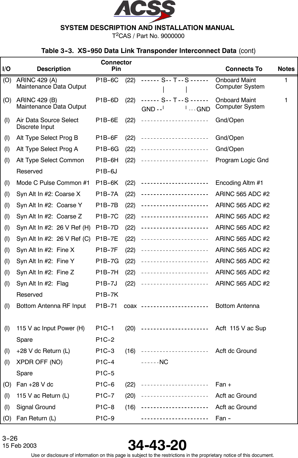
![T2CAS / Part No. 9000000SYSTEM DESCRIPTION AND INSTALLATION MANUAL34-43-2015 Feb 2003Use or disclosure of information on this page is subject to the restrictions in the proprietary notice of this document.4--40Table 4--4. XS--950 Data Link Transponder Interface Description (cont)Connector PinDesignation Functional DescriptionP1B--6A, 6B ARINC 429 MAINTENANCE DATA BUS INPUT: (P1B--6A [A], P1B--6B [B])Two low speed ARINC 429 busses (12.5k bits/second nominal) are provided to interfacebetween the transponder and an onboard maintenance system. The maintenancecomputer interface is designed to work with all airframe models and types.P1B--6C, 6D ARINC 429 MAINTENANCE DATA BUS OUTPUT: (P1B--6C [A], P1B--6D [B])See pins P1B--6A, 6B.P1B--6E AIR DATA SOURCE SOURCE SELECT DISCRETE INPUT:The transponder contains dual inputs for all types of altitude sources. This discrete inputspecifies which of the two inputs are used to obtain altitude information.Ground = Altitude Source No. 2Open = Altitude Source No. 1P1B--6F,P1B--6G,P1B--6HALTITUDE TYPE SELECT PROGRAM INPUT:The Altitude Type Select program pins are used to configure the transponder for the typeof altitude source that is connected to it. The inputs use ground/open logic. The AltitudeType Select Common (pin P1B--6H) can be used to supply a ground.Program PinP1B--6F P1B--6G DefinitionGround Ground Selects Gillham Altitude SourceGround Open Selects ARINC 575 Altitude SourceOpen Ground Selects ARINC 407 Synchro Altitude SourceOpen Open Selects ARINC 429 Altitude SourceP1B--7ATHRUP1B--7JARINC 565 ANALOG AC AIR DATA COMPUTER #2 INPUTS:Second ARINC 565 Analog AC Air Data Computer Input. See pins P1A--4A Thru 4J.P1B--71 BOTTOM ANTENNA RF INPUT:RF input from bottom antenna.P1C--1 XPDR 115 Vac INPUT POWER: (H)This pin along with the XPDR 115 Vac RETURN line (pin P1C--7) provides the 115 Vacpower requirements for the transponder.NOTE: Only --10XXX thru --54XXX transponders accept 115 Vac, 400 Hz input power.If the 115 Vac version is used, the power should be connected througha5ampcircuit breaker, and the pins for the 28 Vdc input (P1C--10 and P1C--3) shouldbe left unconnected.P1C--3 XPDR +28 Vdc RETURN: (L)See pin P1C--10.P1C--4 XPDR OFF (NO) INPUT:This discrete input is used to turn the transponder power supply OFF. It should not beconnected in aircraft installations.](https://usermanual.wiki/ACSS-an-L-3-Communications-and-Thales/TT-950.User-Manual-Part-2/User-Guide-302828-Page-81.png)
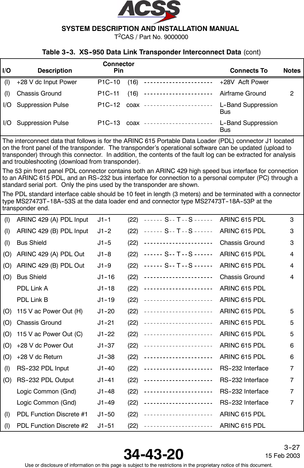
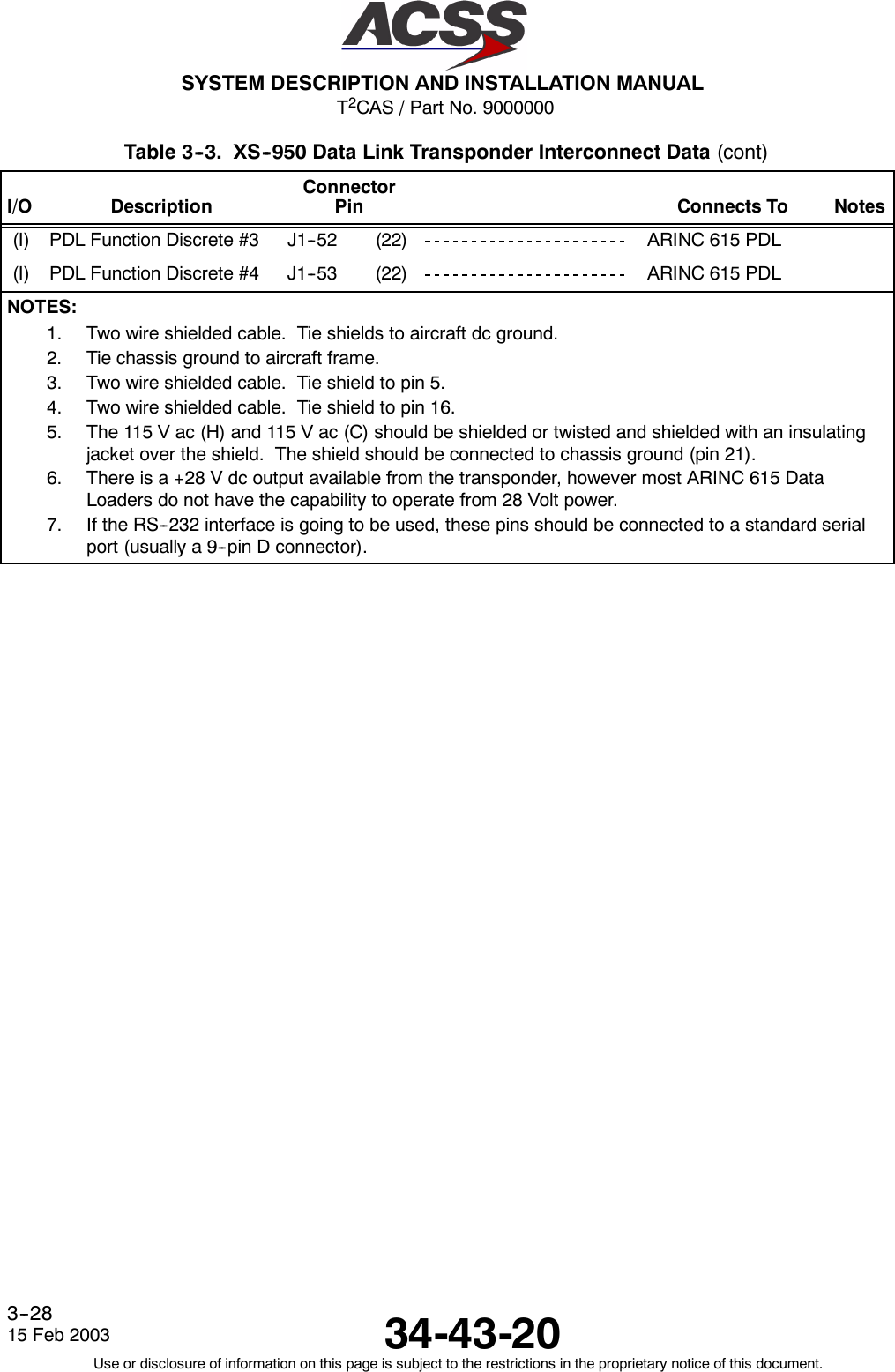
![T2CAS / Part No. 9000000SYSTEM DESCRIPTION AND INSTALLATION MANUAL34-43-20 15 Feb 2003Use or disclosure of information on this page is subject to the restrictions in the proprietary notice of this document.4--41Table 4--4. XS--950 Data Link Transponder Interface Description (cont)Connector PinDesignation Functional DescriptionP1C--6 FAN +28 Vdc OUTPUT: (+)The 28 Vdc version of the transponder can control an externally mounted +28 Vdc fan toprovide cooling air for the transponder. The Fan +28 Vdc output (P1C--6) should beconnected to the positive input of the fan, and the Fan Return (NO) Output (P1C--9)should be connected to the negative input of the fan. The output has the capability todrive a fan that draws up to 200 mA of current. The fan is turned on when the internaltransponder temperature rises above 30 degrees centigrade. In the 115 Vac version ofthe transponder, the outputs are not used.P1C--7 XPDR 115 Vac RETURN: (C)See pin P1C--1.P1C--8 SIGNAL GROUND INPUT:Connect to Aircraft Signal Ground.P1C--9 FAN RETURN (NO): (--)See pin P1C--6.P1C--10 XPDR +28 Vdc INPUT POWER: (H)This pin along with the +28 Vdc RETURN line (P1C--3) provide the 28 Vdc powerrequirements for the transponder.NOTE: Only --55XXX thru --99XXX transponders accept +28 Vdc input power. If the+28 Vdc version is used, the power should be connected through an 8 ampcircuit breaker, and the pins for the 115 Vac input (P1C--1 and P1C--7) shouldbe left unconnected.P1C--11 CHASSIS GROUND INPUT:Connect to aircraft frame.P1C--12,P1C--13MUTUAL SUPPRESSION BUS INPUT/OUTPUT:L--Band suppression coax must be RG--142 or equivalent coaxial cable. P1C--12 andP1C--13 are connected internally. Connection to only one pin is required.The Interface descriptions that follow are for the 53--pin ARINC 615 Portable Data Loader connectorJ1 mounted on the front panel of the transponder. These descriptions are used to make up thecable that is used to interface between the transponder and the ARINC 615 Data Loader or aRS--232 PC Serial Port.J1--1, 2 XPDR ARINC 429 PDL BUS INPUT: (J1--1 [A], J1--2 [B])This differential pair input is a high speed ARINC 429 bus (100k bits/second nominal) isused to input data from the data loader to the transponder. The standards for thisinterface are defined in ARINC 615 “Airborne Computer High Speed Data Loader”.These pins should be connected to pins 1 and 2 of the PDL cable interface.J1--5 INPUT BUS SHIELD:The shields from the input bus (J1--1, 2) should be connected to this pin.](https://usermanual.wiki/ACSS-an-L-3-Communications-and-Thales/TT-950.User-Manual-Part-2/User-Guide-302828-Page-82.png)
![T2CAS / Part No. 9000000SYSTEM DESCRIPTION AND INSTALLATION MANUAL34-43-2015 Feb 2003Use or disclosure of information on this page is subject to the restrictions in the proprietary notice of this document.4--42Table 4--4. XS--950 Data Link Transponder Interface Description (cont)Connector PinDesignation Functional DescriptionJ1--8, 9 XPDR ARINC 429 PDL BUS OUTPUT: (J1--8 [A], J1--9 [B])This differential pair output is a high speed ARINC 429 bus (100k bits/second nominal)used to output data from the transponder to the data loader. The standards for thisinterface are defined in ARINC 615 “Airborne Computer High Speed Data Loader”.These pins should be connected to pins 8 and 9 of the PDL cable interface.J1--16 OUTPUT BUS SHIELD:The shields from the output bus (J1--8, 9) should be connected to this pin.J1--18 PDL LINK A:Connect this pin to pin 18 of the PDL cable interface.J1--19 PDL LINK B:Connect this pin to pin 19 of the PDL cable interface.J1--20, 22 115VacPOWEROUTPUT: (J1--20[H],J1--22[C])These power output pins provide the 115 Vac operating power for the data loader.NOTE: Only the 115 Vac version transponders provide this output. If a +28 Vdc versiontransponder is installed, either the data loader must be able to operate from +28Vdc or the data loader 115 Vac input power must be connected to a sourceexternal to the transponder.The 115 Vac (H) and 115 Vac (C) should be shielded or twisted and shielded with aninsulating jacket over the shield. The shield should be connected to chassis ground (pin21).J1--21 CHASSIS GROUND:Connect 115 Vac power shields to this pin.J1--37, 38 +28 Vdc POWER OUTPUT: (J1--37 [HI], J1--38 [LO])These power output pins provide the +28 Vdc operating power for the data loader. Thesepins are used only if the data loader operates from +28 Vdc.](https://usermanual.wiki/ACSS-an-L-3-Communications-and-Thales/TT-950.User-Manual-Part-2/User-Guide-302828-Page-83.png)
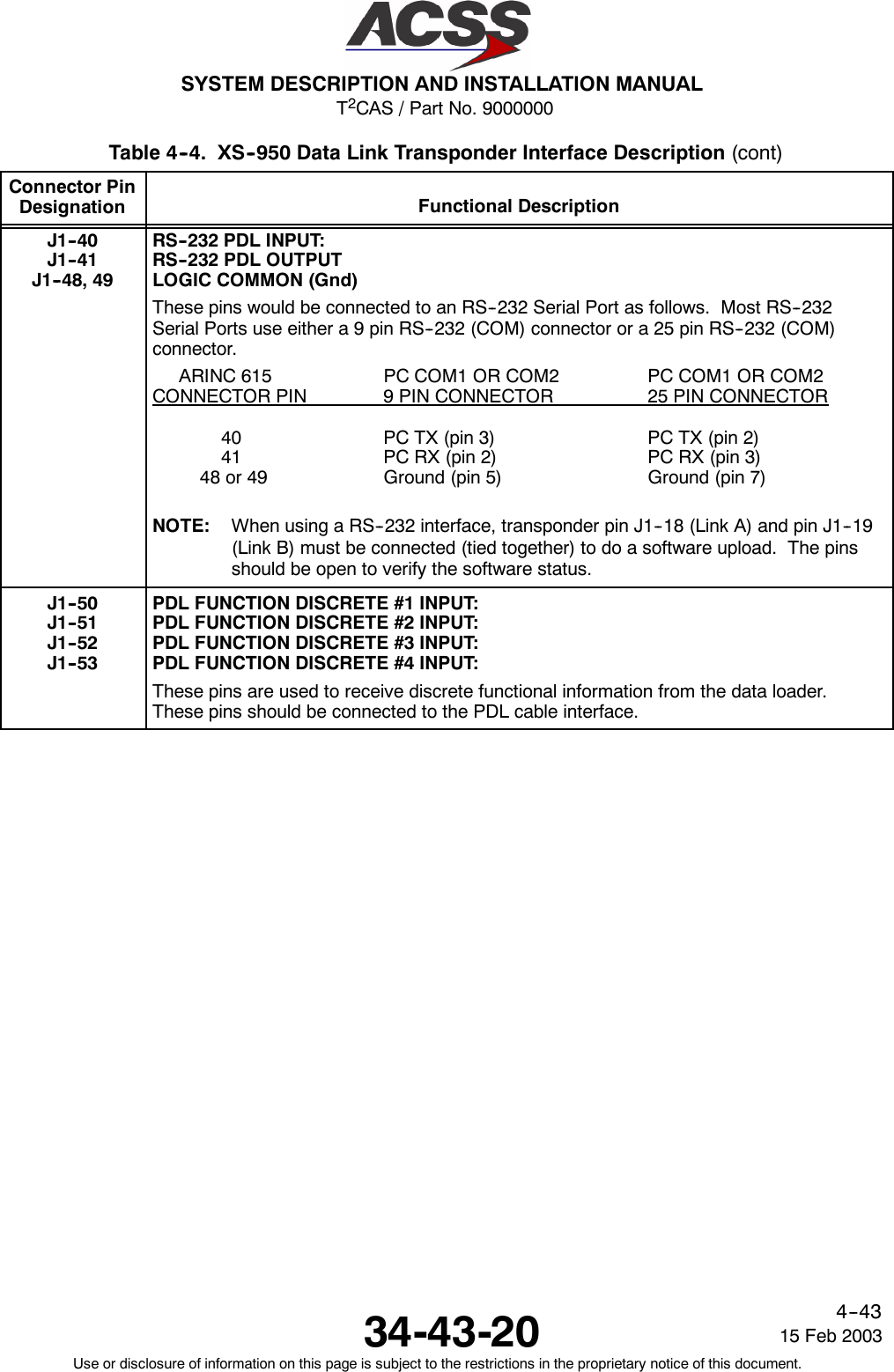
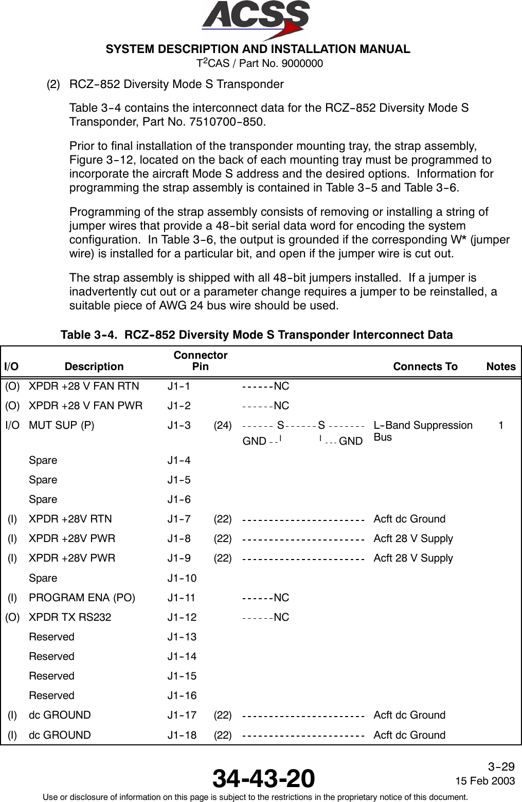
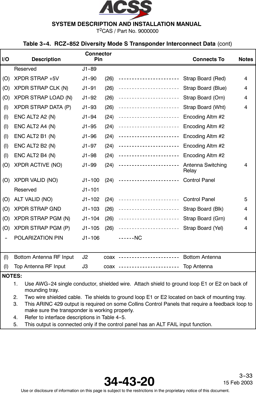
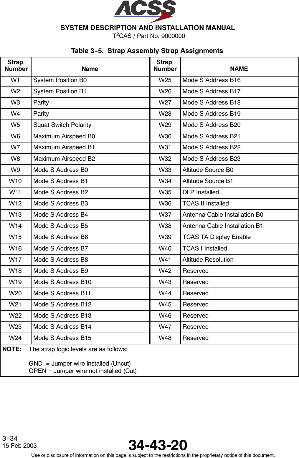
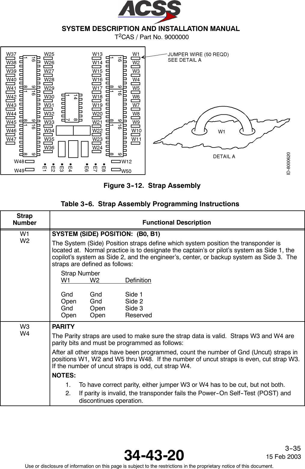
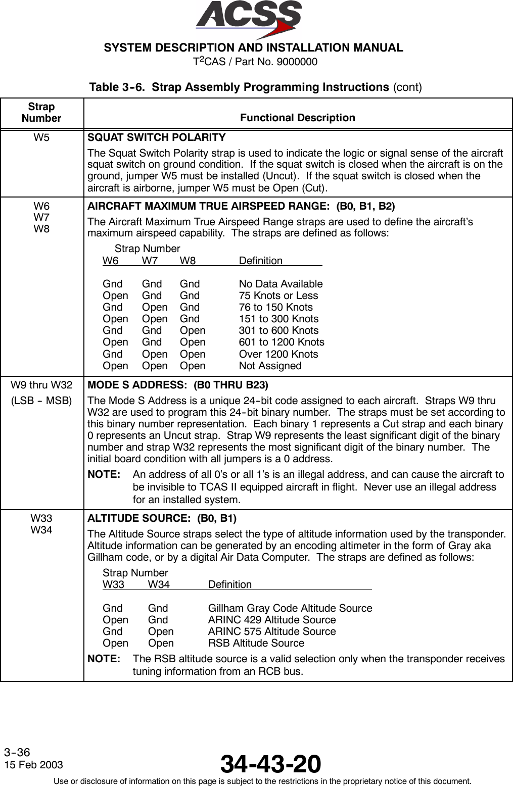
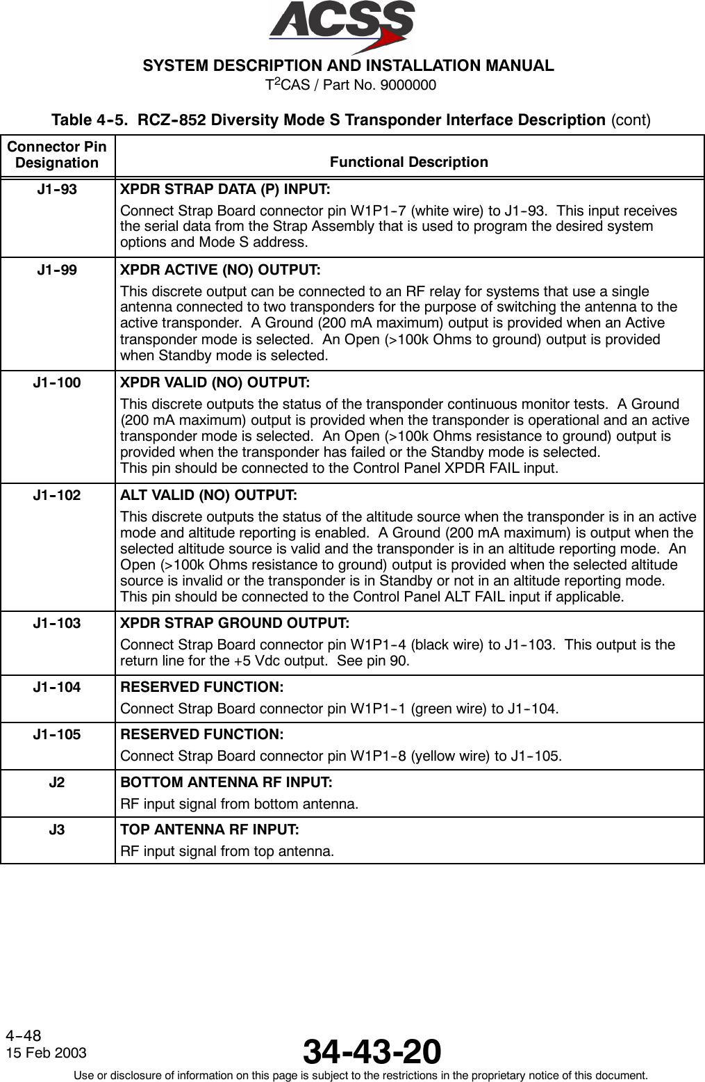
![T2CAS / Part No. 9000000SYSTEM DESCRIPTION AND INSTALLATION MANUAL34-43-2015 Feb 2003Use or disclosure of information on this page is subject to the restrictions in the proprietary notice of this document.4--44Table 4--5. RCZ--852 Diversity Mode S Transponder Interface DescriptionConnector PinDesignation Functional DescriptionJ1--1, 2 XPDR +28 Vdc FAN PWR and +28Vdc FAN RTN: (J1--1 LOW, J1--2 HIGH)The fan discrete outputs supply a switched, filtered +28 Vdc for a dc fan. The RCZ--852Transponder has an internal fan built into the unit, so external cooling is not required.Pins J1--1 and J1--2 should not be connected.J1--3 MUTUAL SUPPRESSION BUS I/O:This bus is a single conductor, shielded bidirectional line that connects to all aircraftL--Band equipment. It is used to desensitize the associated receiver inputs whiletransmitting.J1--7 XPDR +28 Vdc RTN:See pins 8, 9.J1--8J1--9XPDR +28 Vdc PWR:These pins along with there return lines (J1--7 and J1--20) provide the +28 Volt powerrequirements for the transponder.J1--11 PROGRAM ENABLE INPUT:Bench test function. Do not connect this pin in aircraft installations.J1--12 XPDR RS232 TX OUTPUT:Bench test function. Do not connect this pin in aircraft installations.J1--17, J1--18J1--19, J1--21DC GROUND INPUT:To be connected to aircraft dc ground.J1--23 XPDR VALID (PO) OUTPUT:This discrete outputs the status of the transponder continuous monitor tests. It is thesame as the XPDR VALID (NO) output (J1--100) except the discrete is a positive/openlogic. A +28 Vdc (200 mA maximum) is provided when the transponder is operationaland an active transponder mode is selected. An Open (>100k Ohms resistance toground) output is provided when the transponder has failed or the standby mode isselected.J1--24 XPDR RS232 RX INPUT:Bench test function. Do not connect this pin in aircraft installations.J1--25 PROGRAM +15 Vdc OUTPUT:Bench test function. Do not connect this pin in aircraft installations.J1--26, 27 XPDR TO TCAS ARINC 429 BUS OUTPUT: (J1--26 [A], J1--27 [B])This differential pair output is a high speed ARINC 429 bus (100k bits/second nominal)that sends data to the TCAS computer unit. The data bus conforms to the ARINC 718and ARINC 735A standards for TCAS to transponder interface.J1--28, 29 XPDR TO DLP A/B ARINC 429 BUS OUTPUT: (J1--28 [A], J1--29[B])This differential pair output is a high speed ARINC 429 bus (100k bits/second nominal)that sends data to an airborne data link processor (ADLP) system. The data bus is usedto transfer COMM--A and COMM--B messages between the two systems and conforms tothe ARINC 718 standard for ADLP to transponder interface.](https://usermanual.wiki/ACSS-an-L-3-Communications-and-Thales/TT-950.User-Manual-Part-2/User-Guide-302828-Page-85.png)
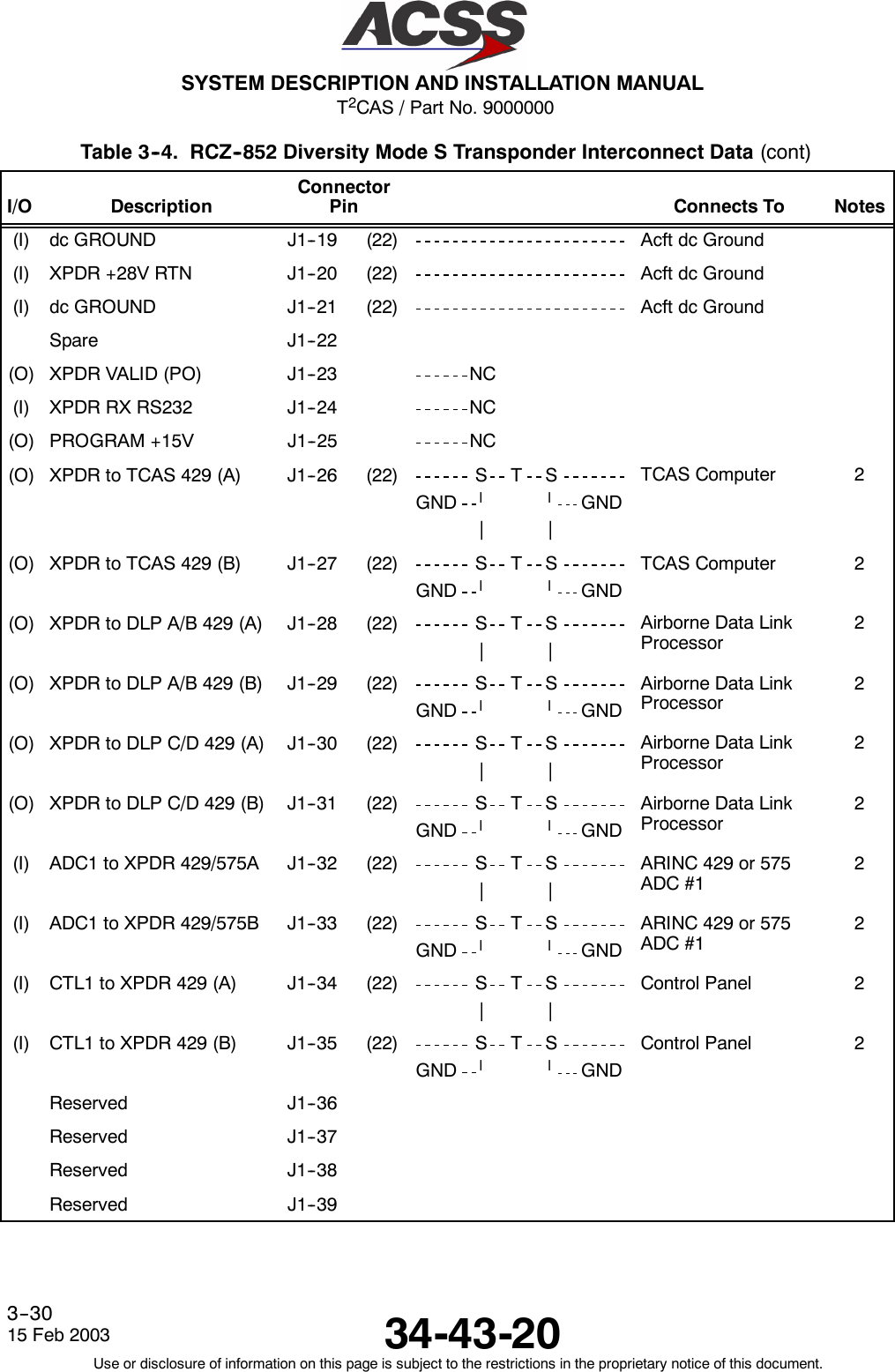
![T2CAS / Part No. 9000000SYSTEM DESCRIPTION AND INSTALLATION MANUAL34-43-20 15 Feb 2003Use or disclosure of information on this page is subject to the restrictions in the proprietary notice of this document.4--45Table 4--5. RCZ--852 Diversity Mode S Transponder Interface Description (cont)Connector PinDesignation Functional DescriptionJ1--30, 31 XPDR TO DLP C/D ARINC 429 BUS OUTPUT: (J1--30 [A], J1--31 [B])This differential pair output is a high speed ARINC 429 bus (100k bits/second nominal)that sends data to an airborne data link processor (ADLP) system. The data bus is usedto transfer COMM--C and COMM--D messages between the two systems and conformsto the ARINC 718 standard for ADLP to transponder interface.J1--32, 33 ADC1 TO XPDR ARINC 429/575 BUS INPUT: (J1--32 [A], J1--33 [B])This differential pair input is a low speed ARINC 429 or 575 bus that inputs uncorrectedpressure altitude (ARINC label 203) from an altitude source. The input accepts eitherARINC 429 or 575 data format, which is selected by the altitude source straps (W33,W34) on the Strap Assembly. The ALT SRC SEL2 (NO) discrete, pin 60, selects eitherADC1 or ADC2.J1--34, 35 CTL1 TO XPDR ARINC 429 BUS INPUT: (J1--34 [A], J1--35 [B])The transponder can receive data from the control panel(s) on the CTL1 TO XPDR andCTL2 TO XPDR data busses. The bus used, is selected by the CTL SRC SEL1 (NO)DISCRETE. See pin 61. The data bus not selected will not be processed. Thesedifferential pair inputs are low speed ARINC 429 busses (12.5k bits/second nominal) thattransmits tuning information from the control panel to the transponder. The transponderexpects to receive ARINC labels 016 and 031 at an update rate of 100 to 200milliseconds. Also see CTL2 TO XPDR ARINC 429 bus input (pins 48 and 49).J1--40, 41 TCAS TO XPDR ARINC 429 BUS INPUT: (J1--40 [A], J1--41 [B])This differential pair input is a high speed ARINC 429 bus (100k bit/second nominal) thatreceives data from a T2CAS computer unit. The data bus conforms to the ARINC 718and ARINC 735A standards for TCAS to transponder interface.J1--42, 43 DLP A/B TO XPDR ARINC 429 BUS INPUT: (J1--42 [A], J1--43 [B])This differential pair input is a high speed ARINC 429 bus (100k bits/second nominal) thatreceives data from an airborne data link processor (ADLP) system. The data bus is usedto transfer COMM--A and COMM--B messages between the two systems and conforms tothe ARINC 718 standard for ADLP to transponder interface.J1--44, 45 DLP C/D TO XPDR ARINC 429 BUS INPUT: (J1--44 [A], J1--45 [B])This differential pair input is a high speed ARINC 429 bus (100K bits/second nominal) thatreceives data from an airborne data link processor (ADLP) system. The data bus is usedto transfer COMM--C and COMM--D messages between the two systems and conformsto the ARINC 718 standard for ADLP to transponder interface.J1--46, 47 ADC2 TO XPDR ARINC 429/575 BUS INPUT: (J1--46 [A], J1--47 [B])See pins J1--32, 33J1--48, 49 CTL2 TO XPDR ARINC 429 BUS INPUT: (J1--48 [A], J1--49 [B])See pins J1--34, 35J1--50, 51 XPDR TO CTL ARINC 429 BUS OUTPUT: (J1--50 [A], J1--51 [B])This differential pair output is a low speed ARINC 429 bus (12.5k bits/second) thattransmits control panel input data back to the control panel for verification purposes.These output pins are connected only on some Collins control panels that requirefeedback from the transponder to make sure it is operating properly.](https://usermanual.wiki/ACSS-an-L-3-Communications-and-Thales/TT-950.User-Manual-Part-2/User-Guide-302828-Page-86.png)
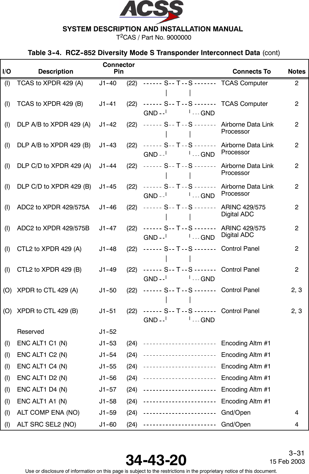
![T2CAS / Part No. 9000000SYSTEM DESCRIPTION AND INSTALLATION MANUAL34-43-2015 Feb 2003Use or disclosure of information on this page is subject to the restrictions in the proprietary notice of this document.4--46Table 4--5. RCZ--852 Diversity Mode S Transponder Interface Description (cont)Connector PinDesignation Functional DescriptionJ1--53 thru 58,J1--67 thru 71ENCODING ALTIMETER NO.1 ELEVEN BIT INPUT:Transponder input from Encoding Altimeter No. 1. These eleven lines from the altitudeencoder comprise an 11--bit word representative of the aircraft’s uncorrected pressurealtitude.J1--59 ALT COMP ENA (NO) DISCRETE INPUT:This discrete input enables or disables altitude comparison when dual Gillham altitudesources are selected via the ALTITUDE SOURCE strap. If comparison is enabled (J1--59Grounded), the two altitude sources (ENC ALT1 and ENC ALT2) are compared, and areconsidered valid if they are within 500 feet. If the altitude comparison is enabled and itfails, the altitude data is considered invalid in Mode S replies and altitude data sent toTCAS. If comparison is disabled (J1--59 Open), only the selected altitude source is used.This discrete has no effect if ARINC 429 or 575 altitude sources are used.NOTE: For installations with TCAS that use Gillham encoding altimeter sources, twoencoding altimeter sources must be used, and pin J1--59 must be enabled(Grounded).J1--60 ALT SRC SEL2 (NO) DISCRETE INPUT:This discrete input allows selection of one of two altitude sources. An Open causes thetransponder to use altitude source No.1, and a Ground causes the transponder to usealtitude source No.2. The altitude data sent to TCAS and used for transponder replies isderived from the selected source.J1--61 CTL SRC SEL1 (NO) DISCRETE INPUT:This discrete input is used to select one of two ARINC 429 control tuning ports. AGround on this pin causes the transponder to use CTL1 TO XPDR bus for tuning data,and an Open causes the transponder to use CTL2 TO XPDR bus for tuning data. Theinput is used only when the transponder tuning source is an ARINC 429 source in astand--alone transponder system. When an RSB tuning source is used, the input isignored.J1--64, 65 FMS TO XPDR ARINC 429 BUS INPUT: (J1--64 [A], J1--65 [B])This differential pair input is a low speed ARINC 429 bus (12.5k bits/second nominal) thatreceives basic transponder control data (label 031) and AIS flight ID (labels 233, 234,235, and 236) from a Flight Management System (FMS).J1--72 XPDR STANDBY (NO) INPUT:This discrete input is connected to the Control Panel STANDBY/ON output. The inputselects the active or standby status of the transponder. A ground causes the transponderto be in Standby, and an Open causes the transponder to be active. The input is usedonly when the transponder tuning source is an ARINC 429 source in a stand--alonetransponder system. When an RCB tuning source is used, the input is ignored.NOTE: If using a Collins CTL--92 Controller, this pin is not used.](https://usermanual.wiki/ACSS-an-L-3-Communications-and-Thales/TT-950.User-Manual-Part-2/User-Guide-302828-Page-87.png)
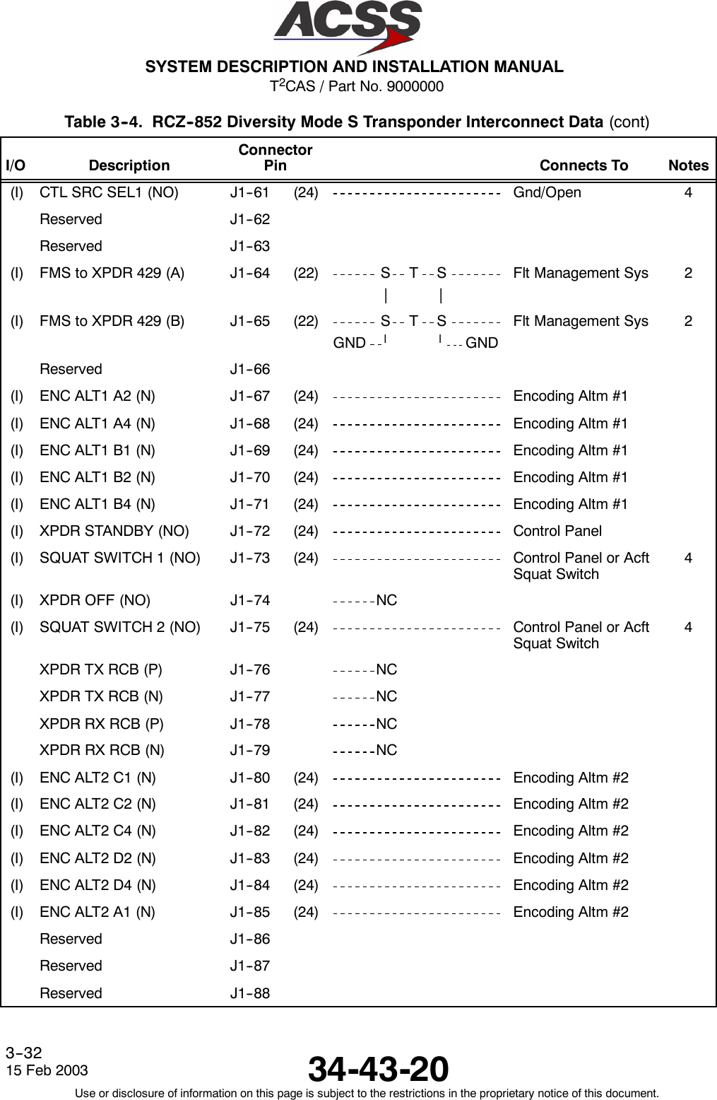
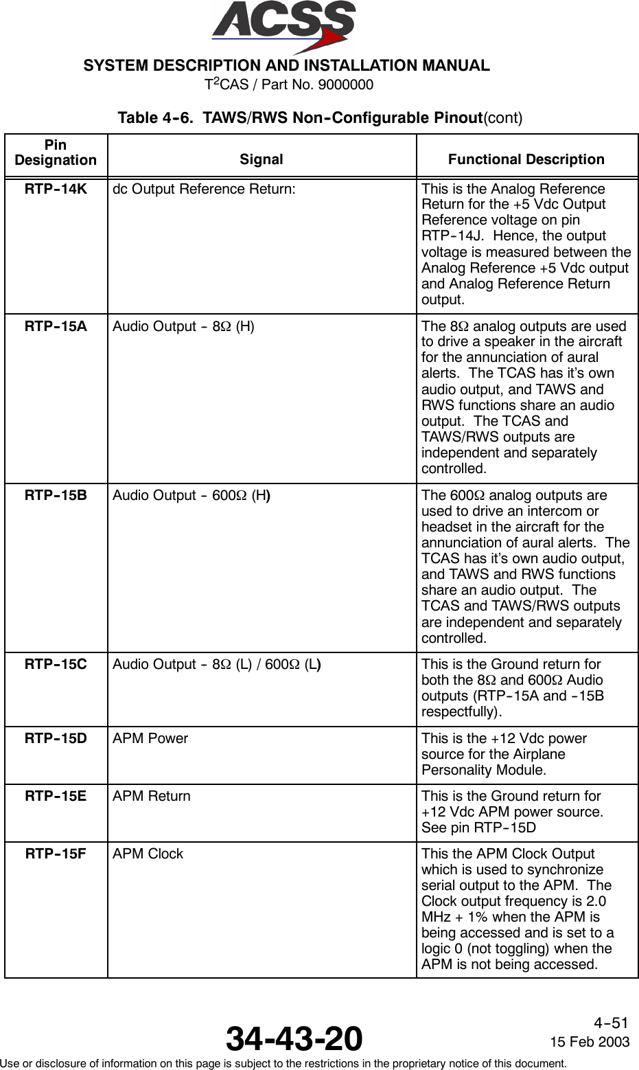
![T2CAS / Part No. 9000000SYSTEM DESCRIPTION AND INSTALLATION MANUAL34-43-2015 Feb 2003Use or disclosure of information on this page is subject to the restrictions in the proprietary notice of this document.4--50•A listing of the TAWS/RWS Input Data Signals, LRUs providing those signals, their datadefinitions (i.e. Analog signal type, A429 Label, etc.) and the minimum requirements thatmust be met by that specific input signal in order for TAWS/RWS to function withinspecification.A. TAWS/RWS Pinout and Pin Descriptions (Non--Configurable)This section contains the non--configurable pin assignments for the GCAM functionality(Table 4--6).Table 4--6. TAWS/RWS Non--Configurable PinoutPinDesignation Signal Functional DescriptionRightTopPlug(RTP)RTP--1A, --1B ARINC 453 Terrain Display Output No. 1:(RTP--1A [A], RTP--1B [B])A453 OutputRTP--1E, --1F ARINC 453 Terrain Display Output No. 2:(RTP--1E [A], RTP--1F [B])A453 OutputRTP--8G, --8H Glide Slope Low Level Deviation No. 1:(RTP--8G [+], RTP--8H [--])Analog ILS InputRTP--8J, --8K Localizer Low Level Deviation No. 1:(RTP--8J [+], RTP--8K [--])Analog ILS InputRTP--9C, --9D Glide Slope Low Level Deviation No. 2:(RTP--9C [+], RTP--9D [--])Analog ILS InputRTP--9E, --9F Localizer Low Level Deviation No. 2:(RTP--9E [+], RTP--9F [--])Analog ILS InputRTP--14E dc Total Air Temperature Return Analog dc TAT ReturnRTP--14F,--14G, --14Hdc Altitude Rate A575/595:(RTP--14F [Signal], --14G [Ref+], --14H [Ref--])Analog dc A575/595RTP--14J dc Output Reference +5 Vdc: The T2CAS provides a +5 Vdcprecision reference output as areference voltage for analogsensors which provide aratio--metric output. In mostinstallations the referencevoltage and the signal voltageare monitored so that thetolerance of the reference outputis not critical. This is thepreferred method and eliminatesissues such as grounddifferentials in aircraftinstallations.](https://usermanual.wiki/ACSS-an-L-3-Communications-and-Thales/TT-950.User-Manual-Part-2/User-Guide-302828-Page-91.png)
![T2CAS / Part No. 9000000SYSTEM DESCRIPTION AND INSTALLATION MANUAL34-43-2015 Feb 2003Use or disclosure of information on this page is subject to the restrictions in the proprietary notice of this document.4--52Table 4--6. TAWS/RWS Non--Configurable Pinout(cont)PinDesignation Functional DescriptionSignalRTP--15G APM Serial Data Input: This is the Serial Data Outputfrom T2CAS to the APM SerialData Input. APM Enable(RTP--15J) and APM WriteEnable (RTP--15K) must beenabled before data can bewrittentotheAPM.RTP--15H APM Serial Data Output This is the Serial Data Input toT2CAS from the APM SerialData Output. APM Enable(RTP--15J) must be enabledbefore data can be read from theAPM.RTP--15J APM Enable No. 1 This pin is used to EnableRead/Write access to the APM.An APM Enable Output logic of 1disables Read/Write access tothe APM and a logic 0 enablesAPM Read/Write access. Thispin is used in conjunction withpins RTP--15G (APM serialoutput) and RTP--15H (APMserial input).RTP--15K APM Write Enable No. 1 This pin is used to Enable Writeaccess to the APM. An APMWrite Enable Output logic of 1disables Write access to theAPM and a logic 0 enables APMWrite access. This pin is used inconjunction with pin RTP--15G(APM serial output).Right Middle Plug (RMP)RMP--2H, --2J Radio Altitude ARINC 552/552A #1(RMP--2H [+], RMP--2J [--])Analog Rad Alt InputRMP--2K Radio Altitude Valid Discrete Input #1 +28 Vdc Disc Input. Used withAnalog Rad Alt Input #1(RMP--2H, --2J).](https://usermanual.wiki/ACSS-an-L-3-Communications-and-Thales/TT-950.User-Manual-Part-2/User-Guide-302828-Page-93.png)
![T2CAS / Part No. 9000000SYSTEM DESCRIPTION AND INSTALLATION MANUAL34-43-20 15 Feb 2003Use or disclosure of information on this page is subject to the restrictions in the proprietary notice of this document.4--53Table 4--6. TAWS/RWS Non--Configurable Pinout(cont)PinDesignation Functional DescriptionSignalRMP--5K Air Ground Discrete Input(Weight--On--Wheels)This discrete input to the T2CAScomputer unit indicates thestatus of the Air/Ground orWeight--On--Wheels (WOW)switch. TCAS filters this input tomake sure it remains in a steadystate a minimum of 4 secondsbefore an Air/Ground transitionis recorded. An open indicatesthe aircraft is airborne and aground indicates the aircraft ison the ground.Inputs should be diode isolatedfrom each other.RMP--9C,RMP--9DGPS Data A429 Output(RMP--9C [A], RMP--9D [B])A429 Output H/L. Signal isreserved on TT--950 andTT--951 models (units withoutGPS).RMP--9E, --9F GPS Time Mark RS--422 Input/Output(RMP--9E [A], RMP--9F [B])Signals are GPS Time MarkInputs on TT--950 and TT--951models (units without GPS).Signals are GPS Time MarkOutputs on TT--952 (unit withGPS).RMP--9G,-- 9 HCD General Purpose A429 Output #1(RMP--9G [A], RMP--9H [B])A429 Output H/L. Signals arereserved for TCAS functions,however the ARINC 429 outputbusses are internally connectedand generated by the A6 TAWSCCA.RMP--9J, --9K CD General Purpose A429 Output #2(RMP--9J [A], RMP--9K [B])A429 Output H/L. Signals arereserved for TCAS functions,however the ARINC 429 outputbusses are internally connectedand generated by the A6 TAWSCCA.RMP--13F Landing Gear Discrete Input GND Disc InputRMP--13H,RMP--13JRadio Altitude A429 Input #1(RMP--13H [A], RMP--13J [B])A429 Input H/L. Signals areused by TCAS and TAWS/RWSfunctionsRMP--14K Accelerometer Self Test Output Accelerometer Test OutputRMP--15G Pitch Limit Indicator Output #1 (Reserved) Pitch Limit OutputRMP--15H Pitch Limit Indicator Output #2 (Reserved) Pitch Limit Output](https://usermanual.wiki/ACSS-an-L-3-Communications-and-Thales/TT-950.User-Manual-Part-2/User-Guide-302828-Page-94.png)
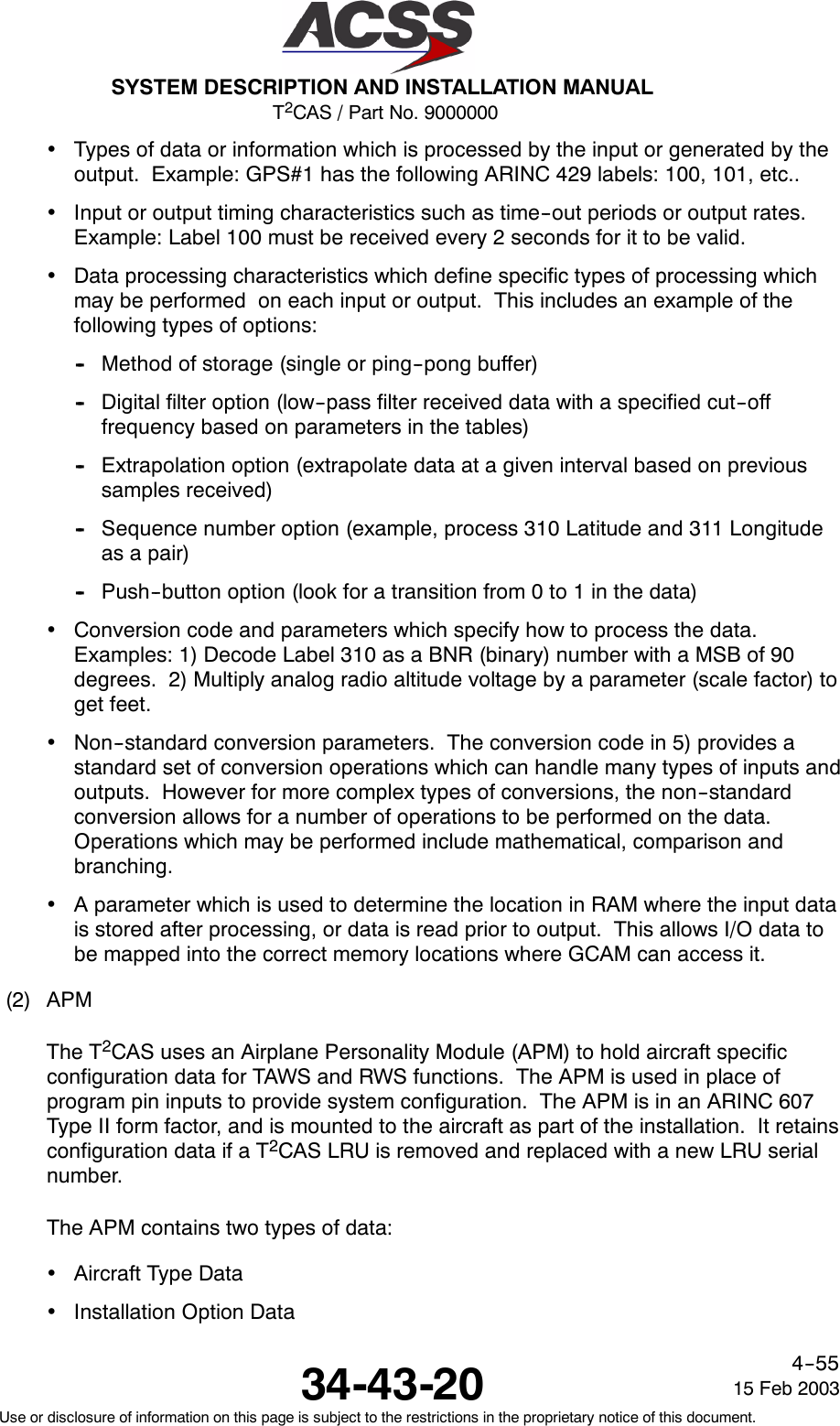
![T2CAS / Part No. 9000000SYSTEM DESCRIPTION AND INSTALLATION MANUAL34-43-2015 Feb 2003Use or disclosure of information on this page is subject to the restrictions in the proprietary notice of this document.4--54Table 4--6. TAWS/RWS Non--Configurable Pinout(cont)PinDesignation Functional DescriptionSignalRight Bottom Plug (RBP)RBP--1E, --1F Computer Power Output(RMP--1E [+], RMP--1F [--])Power Output (+24V)RBP--1G Radio Altitude Valid Discrete Input #3 + 28 Vdc Disc Input. Used withAnalog Rad Alt Input #3(RBP--3F, --3G).RBP--3A, --3B Radio Altitude ARINC 552/552A #2(RBP--3A [+], RBP--3B [--])Analog Rad Alt Input.RBP--3C Radio Altitude Valid Discrete Input #2 +28 Vdc Disc Input. Used withAnalog Rad Alt Input #2(RBP--3A, --3B).RBP--3D, --3E Radio Altitude A429 Input #2(RBP--3D [A], RBP--3E [B])A429 Input H/L. Signals areused by TCAS and TAWSfunctions.RBP--3F, 3G Radio Altitude ARINC 552/552A #3(RBP--3F [+], RBP--3G [--])Analog Rad Alt Input.RBP--10A JTAG Test Bus -- TCK Input Test JTAG Bus.RBP--10D JTAG Test Bus -- TDI Input Test JTAG Bus.RBP--10E JTAG Test Bus -- TDO Output Test JTAG Bus.RBP--10F JTAG Test Bus -- TMS Output Test JTAG Bus.RBP--10G Reserved JTAG Test Bus -- TRST Output Test JTAG Bus.B. TAWS/RWS Data Configuration(1) ASDBThe ASDB is a field loadable database that customizes the T2CAS operation for aspecific aircraft. The ASDB defines the Input/Output definition for the specific aircrafttype, the aircraft climb performance data to support of the TAWS functionality, andthe windshear algorithm coefficient data. The ASDB file is produced with a uniquepart number and can be uploaded to the APM via the RS--232 port or from aCompact Flash card.The ASDB I/O Database contains specific information needed to perform the I/Ofunctionality for the specific aircraft type. The I/O tables define the following types ofinformation for processing system inputs and outputs:•Physical mapping between external systems and T2CAS inputs and outputs.Example, GPS #1 is connected to ARINC 429 Input Bus #5.](https://usermanual.wiki/ACSS-an-L-3-Communications-and-Thales/TT-950.User-Manual-Part-2/User-Guide-302828-Page-95.png)
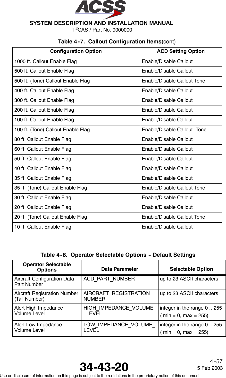
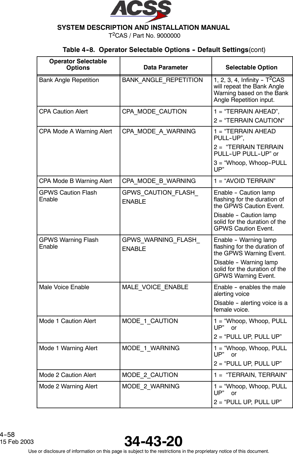
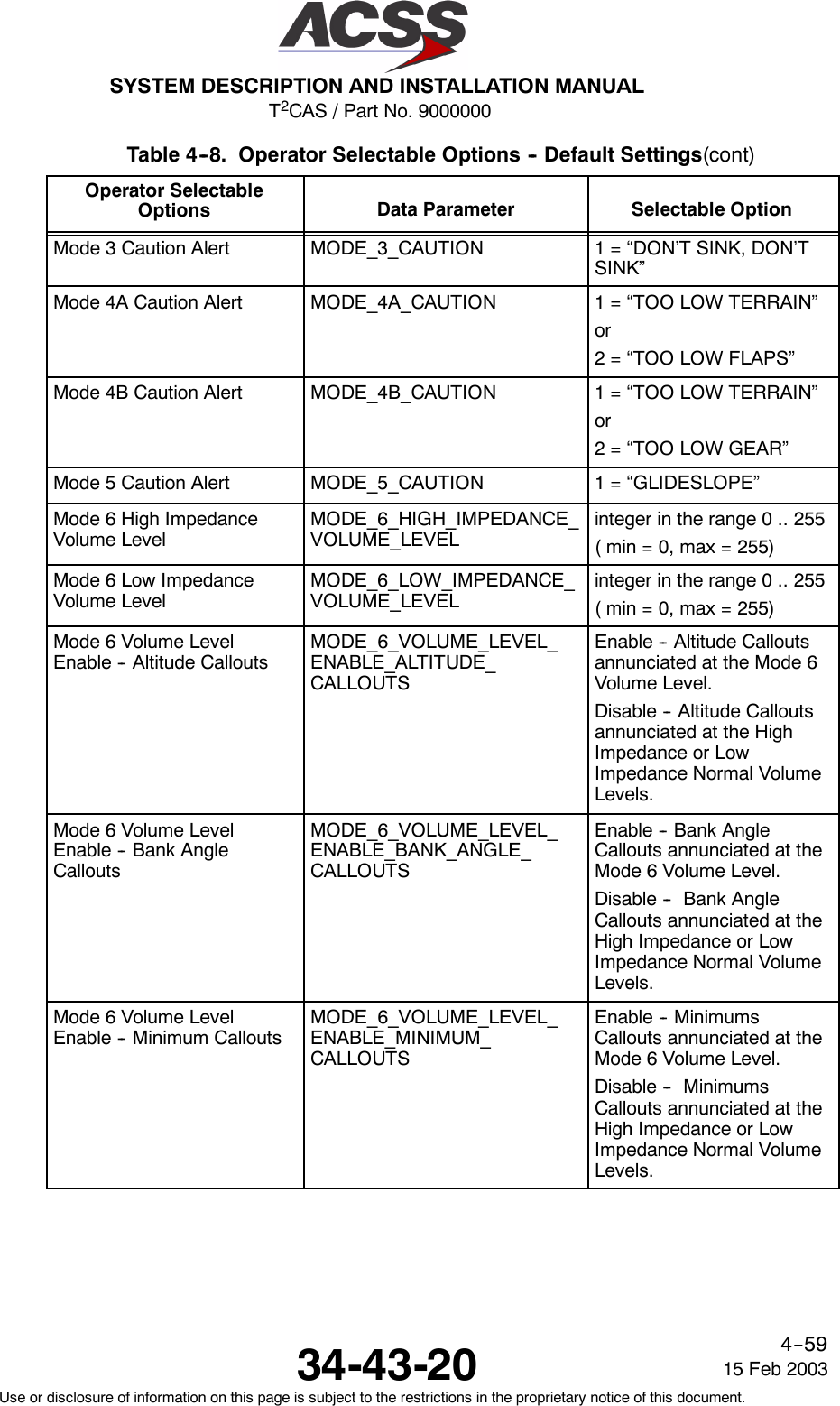
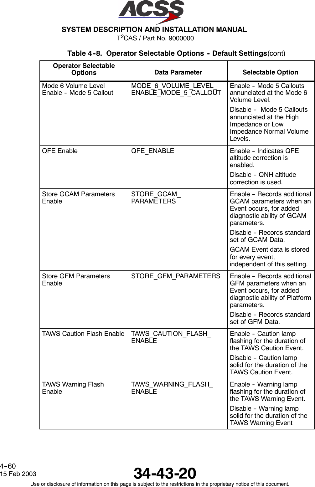
![T2CAS / Part No. 9000000SYSTEM DESCRIPTION AND INSTALLATION MANUAL34-43-2015 Feb 2003Use or disclosure of information on this page is subject to the restrictions in the proprietary notice of this document.4--56The aircraft type data is produced by ACSS, and contains data that is specific toeach particular aircraft type. It contains performance data for that aircraft which isused by TAWS and Windshear functions. It also contains I/O configuration data forthe aircraft that defines and configures the interfaces to the aircraft system. For eachaircraft type, a unique Aircraft Type Data file is produced by ACSS that has a uniquepart number.The Installation Option data replaces the function of program pin (strap) inputs, andallows the installer to customize the operation of the unit at the time of installation.Types of functions that can be configured include display options, discrete outputoptions, altitude callout options, aural annunciation volume control, and other options.A complete list of Operator Selectable Options is contained in Table 4--7 andTable 4--8.The programming of the APM includes the Aircraft Type Data and Installation OptionData, and is accomplished through the RS--232 port on the PDL connector through aLaptop PC, or a Compact Flash Card. The APM data file that contains both types ofdata is generated on a PC with the EDDIT software tool and allows the selection ofthe aircraft type and installation options for that aircraft type. The EDDIT tool builds afile that contains a cyclical redundancy check (CRC) field around the APM data. Witha blank APM installed in the aircraft, the file can be uploaded to the T2CAS unit overthe RS--232 port or through a Compact Flash card. The T2CAS will then program theAPM.Verification of the correct APM contents may be accomplished by the RS--232 port oron the TAWS display. After the APM is programmed, the T2CAS, will output theAircraft Type Data part number and the installation option settings to the RS--232port. Additionally, it will display the APM configuration information on the TAWSdisplay. The data contained in the APM is recorded as part of the aircraftconfiguration data. The software in the T2CAS unit checks the CRC of the data toinsure the file is not corrupted.Table 4--7. Callout Configuration ItemsConfiguration Option ACD Setting OptionCallout Enable Flag [1] Enable/Disable CalloutsBank Angle Callout Enable Flag Enable/Disable Bank AngleCalloutDH/MDA Switch Available Flag Enable/DisableDecision Height Callout Enable Flag Enable/Disable DH CalloutMinimums Callout Enable Flag Enable/Disable Minimums CalloutMinimums--Minimums Callout Enable Flag Enable/Disable CalloutApproaching Decision Height Callout Enable Flag Enable/Disable Approaching DHCalloutApproaching Minimums Callout Enable Flag Enable/Disable ApproachingMinimums Callout](https://usermanual.wiki/ACSS-an-L-3-Communications-and-Thales/TT-950.User-Manual-Part-2/User-Guide-302828-Page-97.png)
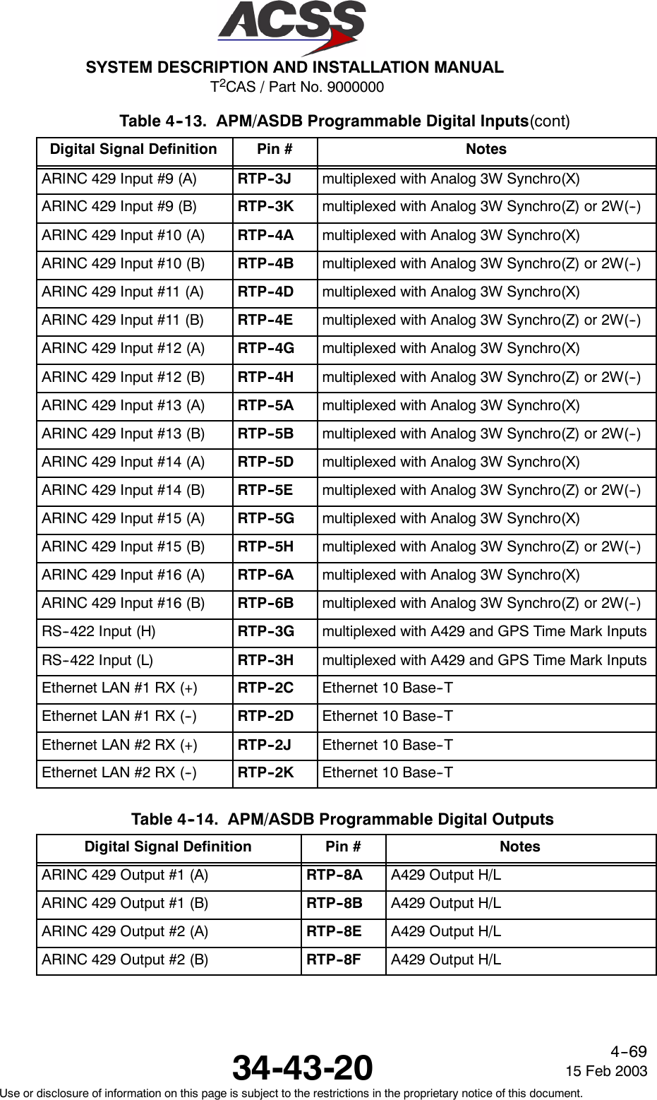
![T2CAS / Part No. 9000000SYSTEM DESCRIPTION AND INSTALLATION MANUAL34-43-2015 Feb 2003Use or disclosure of information on this page is subject to the restrictions in the proprietary notice of this document.4--70Table 4--14. APM/ASDB Programmable Digital Outputs(cont)Digital Signal Definition NotesPin #RS--422 Output (H) RTP--8C RS--422 OutputRS--422 Output (L) RTP--8D RS--422 OutputEthernet LAN #1 TX (+) RTP--2A Ethernet 10 Base--TEthernet LAN #1 TX (--) RTP--2B Ethernet 10 Base--TEthernet LAN #2 TX (+) RTP--2G Ethernet 10 Base--TEthernet LAN #2 TX (--) RTP--2H Ethernet 10 Base--T(a) ARINC 429 SignalsThe T2CAS TAWS/RWS Circuit Card supports up to 18 ARINC 429 receivers, 16of which are APM/ASDB programmable (as shown in Table 4--13). Additionally,4 ARINC 429 transmitters are supported, 2 of which are APM/ASDBprogrammable (as shown in Table 4--14).The ARINC 429 definition for the Source Destination Identifier Bits are shown inTable 4--15.Table 4--15. Source Destination Identifier (SDI)BITS Meaning10 90 0 All--Call0 1 Installation #11 0 Installation #21 1 Installation #3The ARINC 429 Sign Status Matrix Bit definitions for Binary data and BinaryCoded Decimal data are shown in Table 4--16 and Table 4--17 respectfully.Table 4--16. Sign Status Matrix (SSM) [BNR]BITS Meaning30 310 0 Failure Warning0 1 No Computed Data1 0 Functional Test1 1 Normal Operation](https://usermanual.wiki/ACSS-an-L-3-Communications-and-Thales/TT-950.User-Manual-Part-2/User-Guide-302828-Page-111.png)
![T2CAS / Part No. 9000000SYSTEM DESCRIPTION AND INSTALLATION MANUAL34-43-20 15 Feb 2003Use or disclosure of information on this page is subject to the restrictions in the proprietary notice of this document.4--71Table 4--17. Sign Status Matrix (SSM) [BCD]BITS Meaning30 310 0 North/Plus0 1 No Computed Data1 0 Functional Test1 1 UndefinedARINC 429 inputs are classified as one of the following: high speed (H), lowspeed (L) or either (H/L). The A429 receivers are capable of receiving high orlow speed data through APM configuration. The ports are designated H or L ifthey are designated for a function with a known bus speed, otherwise H/L isassigned (there is no hardware difference between the H, L or H/L ports).ARINC 429 outputs are also classified as either high speed (H), low speed (L) orselectable (H/L). A429 outputs designated as H/L speed are capable ofoperating in either high or low speed modes, selectable by the APM through theASDB database.(b) Ethernet 10 Base--T SignalsEthernet 10 Base--T is specified in IEEE Standard 802.3 Ethernet 10 Base--Tprovides communication at a data rate of 10 MBPS over two pairs of wires,where one twisted pair is used to receive data and the other twisted pair is usedto transmit data. Segments of approximately 100 meters in length can beconstructed when twisted pair wire that meets the EIA/TIA Category 3 wirespecifications is used.(c) RS--422 SignalsThe TAWS/RWS card has an RS--422 Input bus which is multiplexed on thesame pins as an ARINC 429 Input bus. The RS--422 Input Bus meets theelectrical requirements in EIA/TIA--422--B.The RS--422 Input Bus has an input impedance on each pin relative to ground of≥9k Ohms and a differential input impedance between + and -- pins of ≥9kOhms.NOTE: This is due to the fact the input is multiplexed with an ARINC 429Receiver.The RS--422 Output Bus has an output impedance of 75 ±5 Ohms distributedequally between the + and -- outputs.(d) GPS Time MarkThe GPS Time Mark Input accepts RS--422 GPS Time Mark signals from anARINC--743A GPS.](https://usermanual.wiki/ACSS-an-L-3-Communications-and-Thales/TT-950.User-Manual-Part-2/User-Guide-302828-Page-112.png)
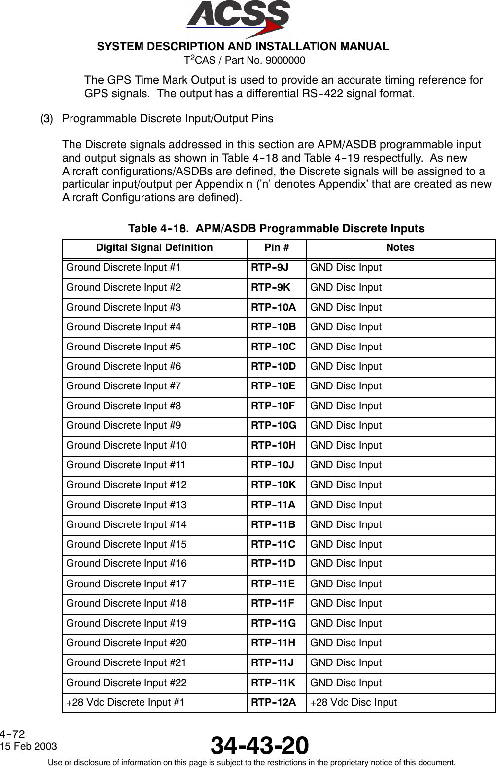
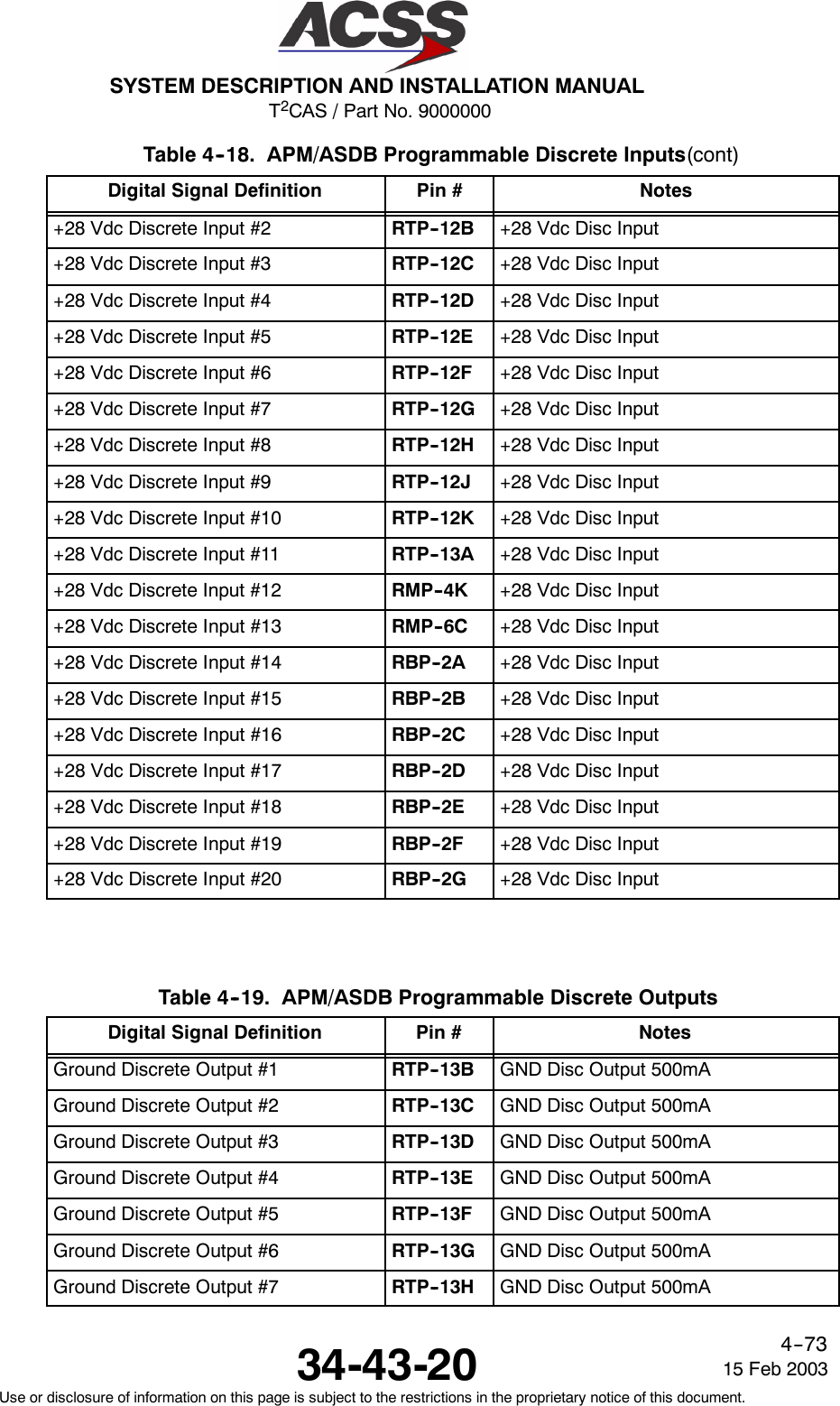
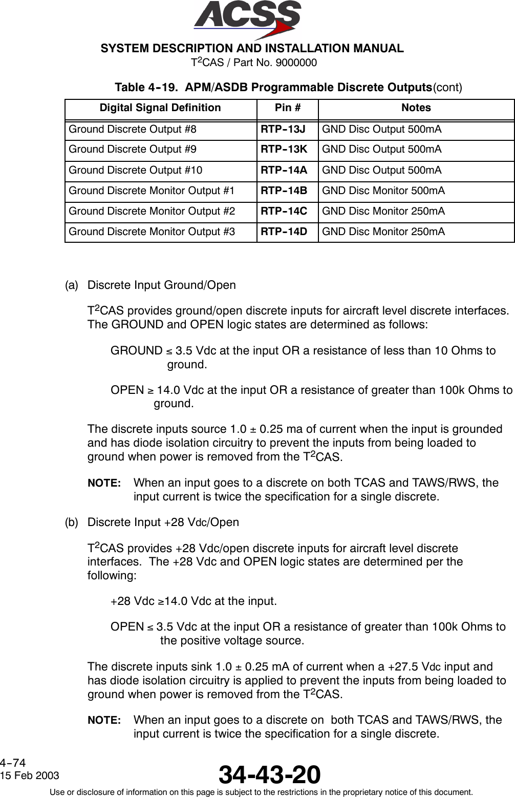
![T2CAS / Part No. 9000000SYSTEM DESCRIPTION AND INSTALLATION MANUAL34-43-20 15 Feb 2003Use or disclosure of information on this page is subject to the restrictions in the proprietary notice of this document.4--75(c) Discrete Output Ground/Open 500 mAThe discrete outputs listed in this section pertain to ground/open discrete outputsfor the TAWS/RWS function.The discrete output in the GROUND logic state has an output voltage of ≤3.0Vdc when sinking 500 mA of current and an output voltage of ≤1.5 Vdc whensinking 100 mA of current.The discrete output in the OPEN logic state has an output impedance of ≥2.4MOhms to ground for voltages applied to the output of 0.0 to +33.0 Vdc and ≥100kOhms to ground for voltages applied to the output of +33.0 to +36.0 Vdc.The discrete output circuitry contains a monitor which detects if an over--currentcondition has occurred and is able to withstand a direct short to +28 Vdc for anindefinite period of time.Additionally, the discrete output circuitry contains a monitor which detects if theoutput voltage is incorrect for the driven state of the discrete output.D. TAWS/RWS Input Data SignalsThe T2CAS TAWS/RWS functions requires a minimum set of data that is needed toperform within the standard specifications (detailed in RTCA DO--161A [GPWS],TSO--C151a [TAWS] and TSO--C117a [RWS] ). This section contains the minimum set ofTAWS/RWS data signals and the information/guidelines that is needed by the installer toobtain the correct analog or digital signal on a specific aircraft. Since the TAWS/RWS I/Ofunction is very flexible, the installer must keep in mind that the data signal sources listedin this section are typical for the specified signal and that the I/O function can be modifiedvia the ASDB to accommodate other non--typical signal sources.The information in this section will include External Sensor Input accuracies for specificinputs to T2CAS GCAM function. These External Sensor accuracies must be met for thespecified inputs in order for the T2CAS to perform the TAWS/RWS functions. Inputs toT2CAS GCAM function consists of errors due to the external system sensor plusmeasurement errors within the T2CAS LRU. In addition, for analog inputs the internalT2CAS errors due to the hardware circuit are also considered.(1) Vertical Speed (Digital/Analog)The TAWS/RWS Vertical Speed parameter is updated from an Inertial, GPS or AirData Computer source. The IRS/GPS source can be any one of the following :ADIRS, GPIRS, IRS, AHRS, GPS and ADC.NOTE: When Vertical Speed is unavailable from an IRS or GPS source, thealternate variable Baro Altitude Rate will be used from an ADC source.The minimum External Sensor input accuracy accepted is 68 ft/min when GPS is thesource or 30 ft/min when IRS, ADIRS, AHRS or ADC (alternate Baro Altitude Ratevariable) is the source.](https://usermanual.wiki/ACSS-an-L-3-Communications-and-Thales/TT-950.User-Manual-Part-2/User-Guide-302828-Page-116.png)
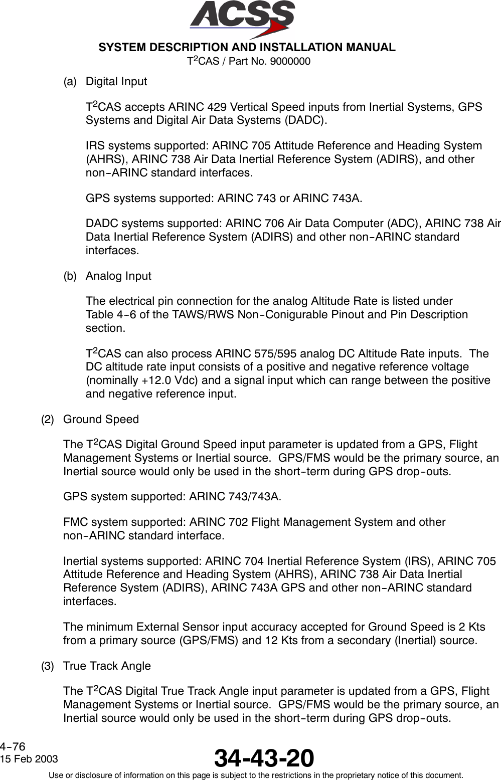
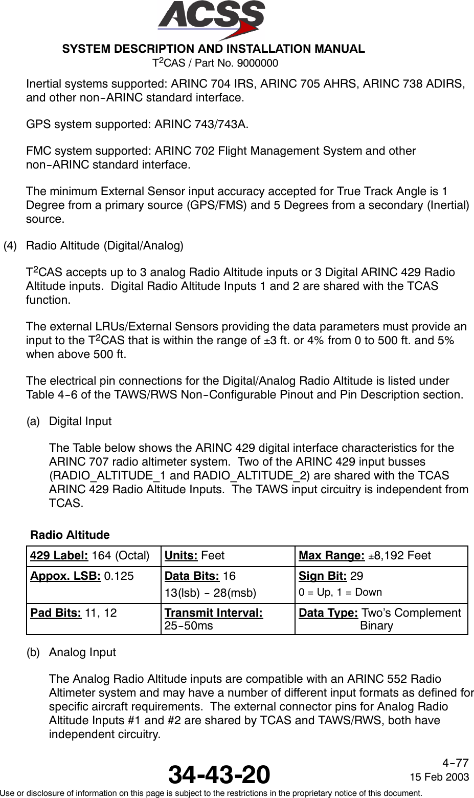
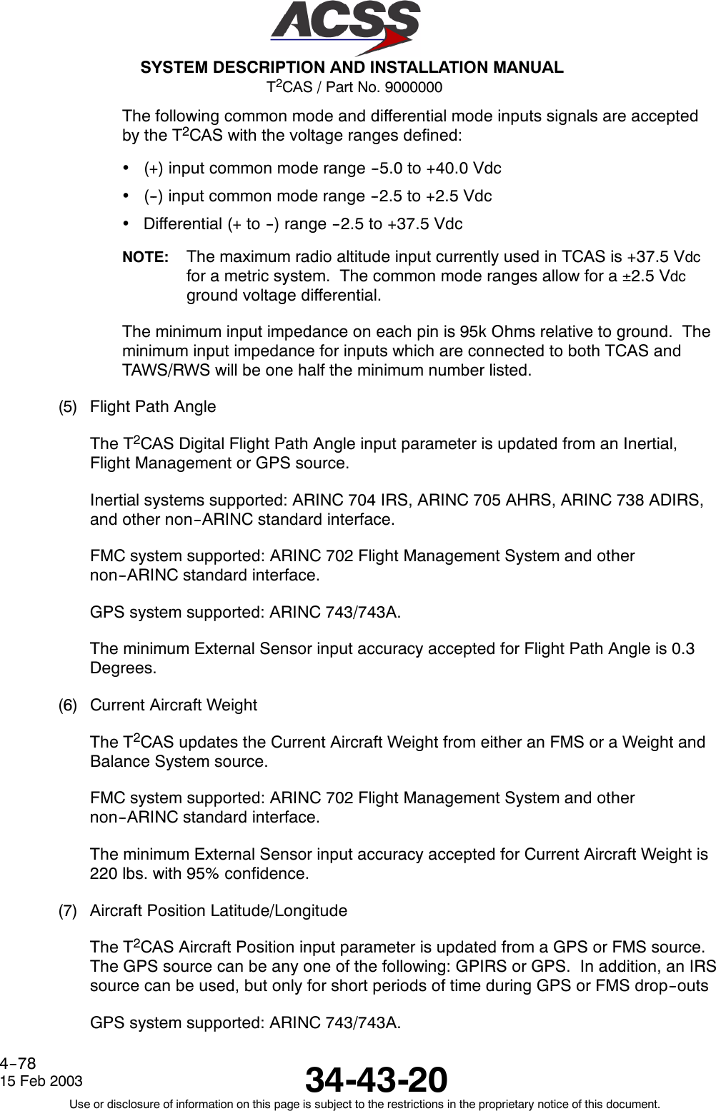
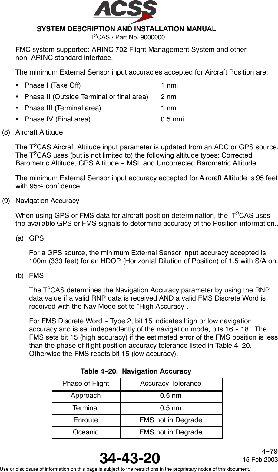
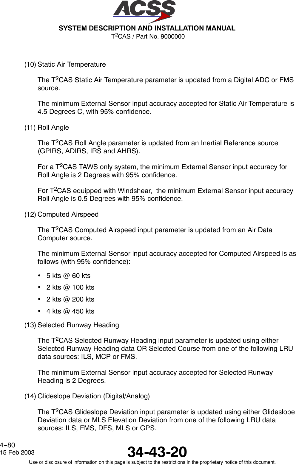
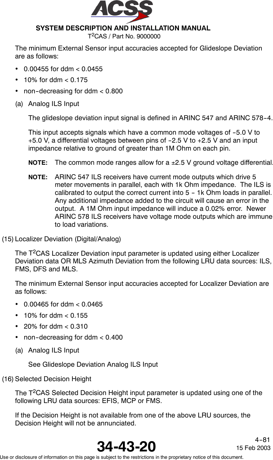
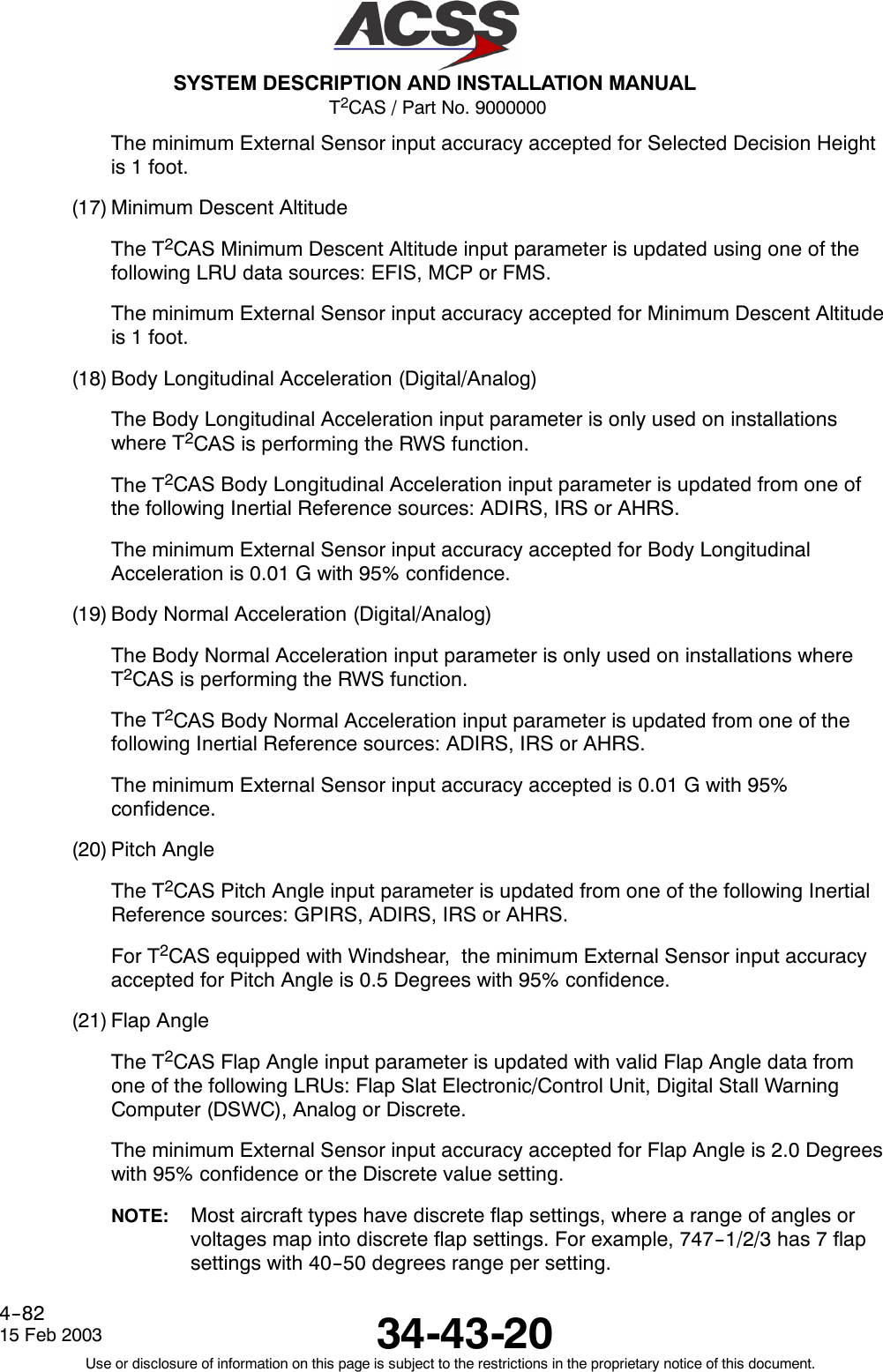
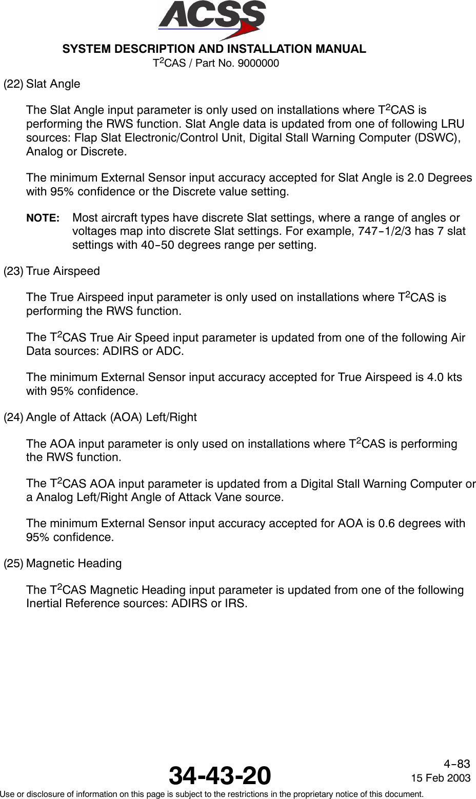
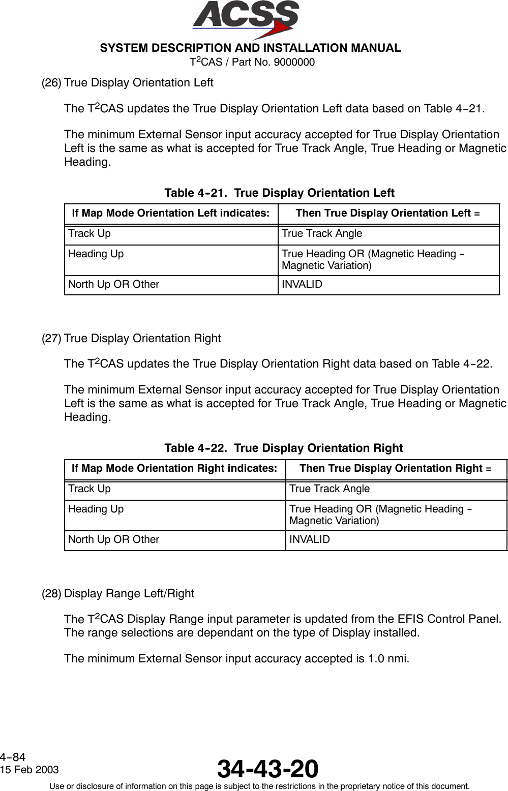
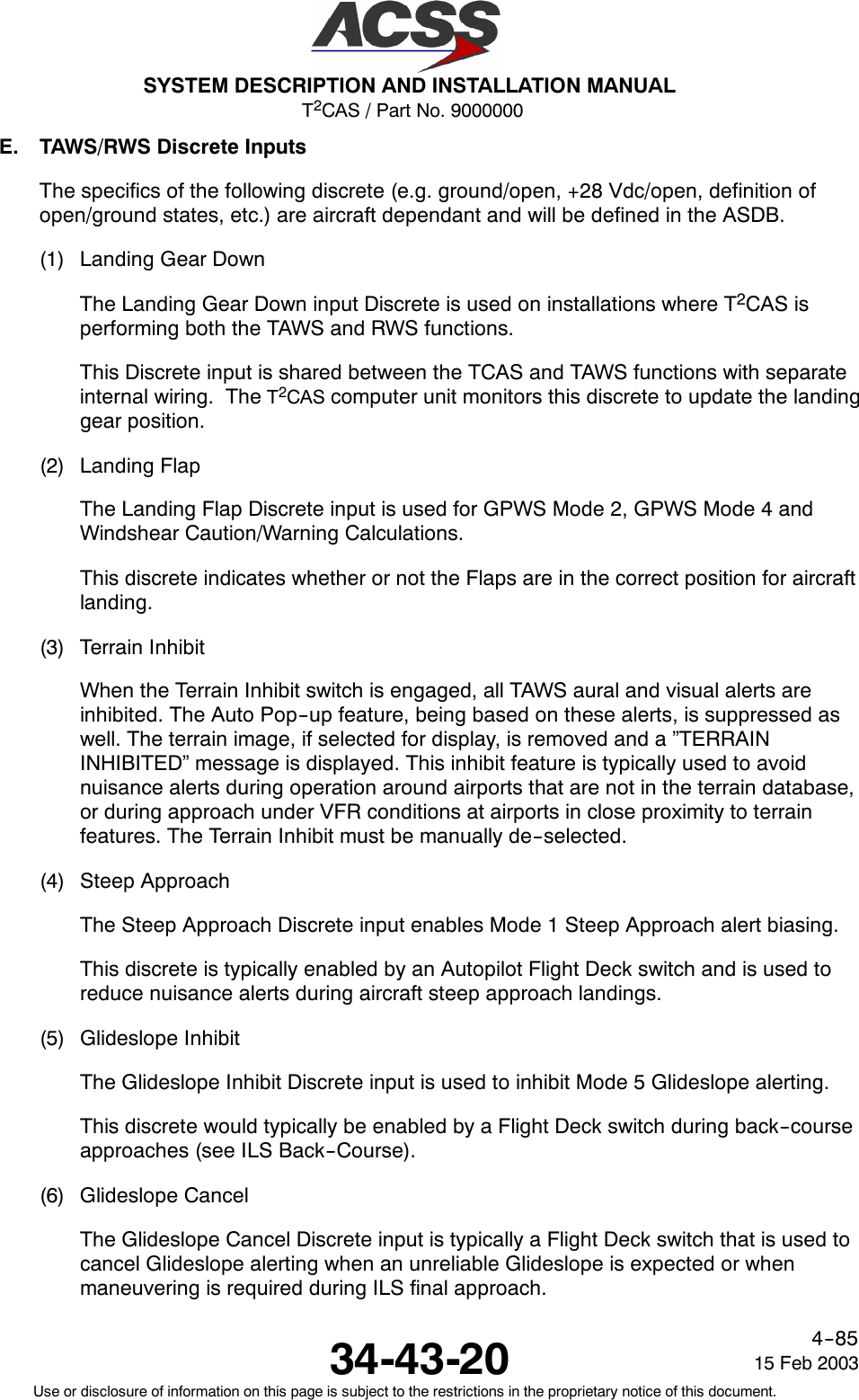
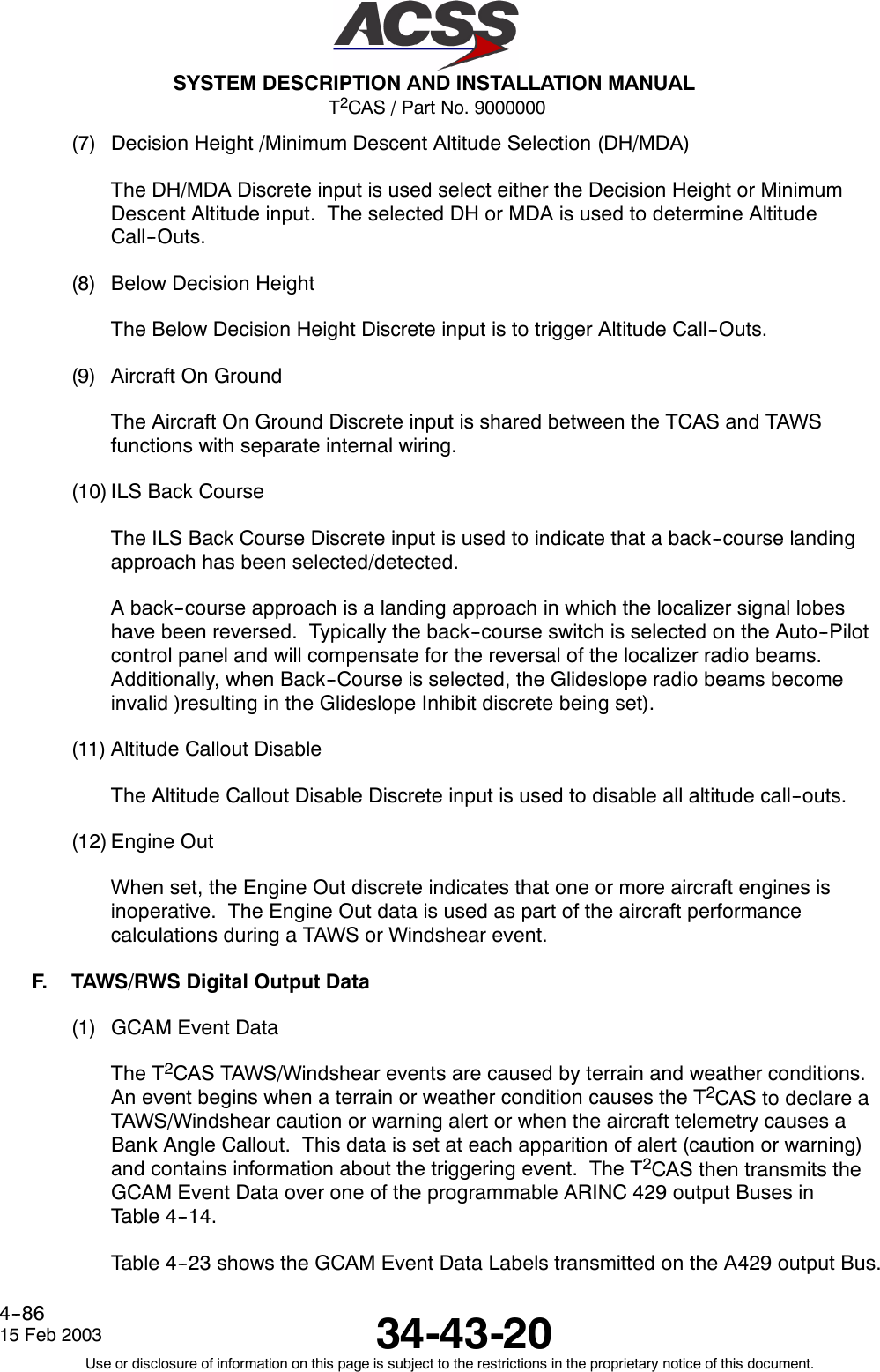
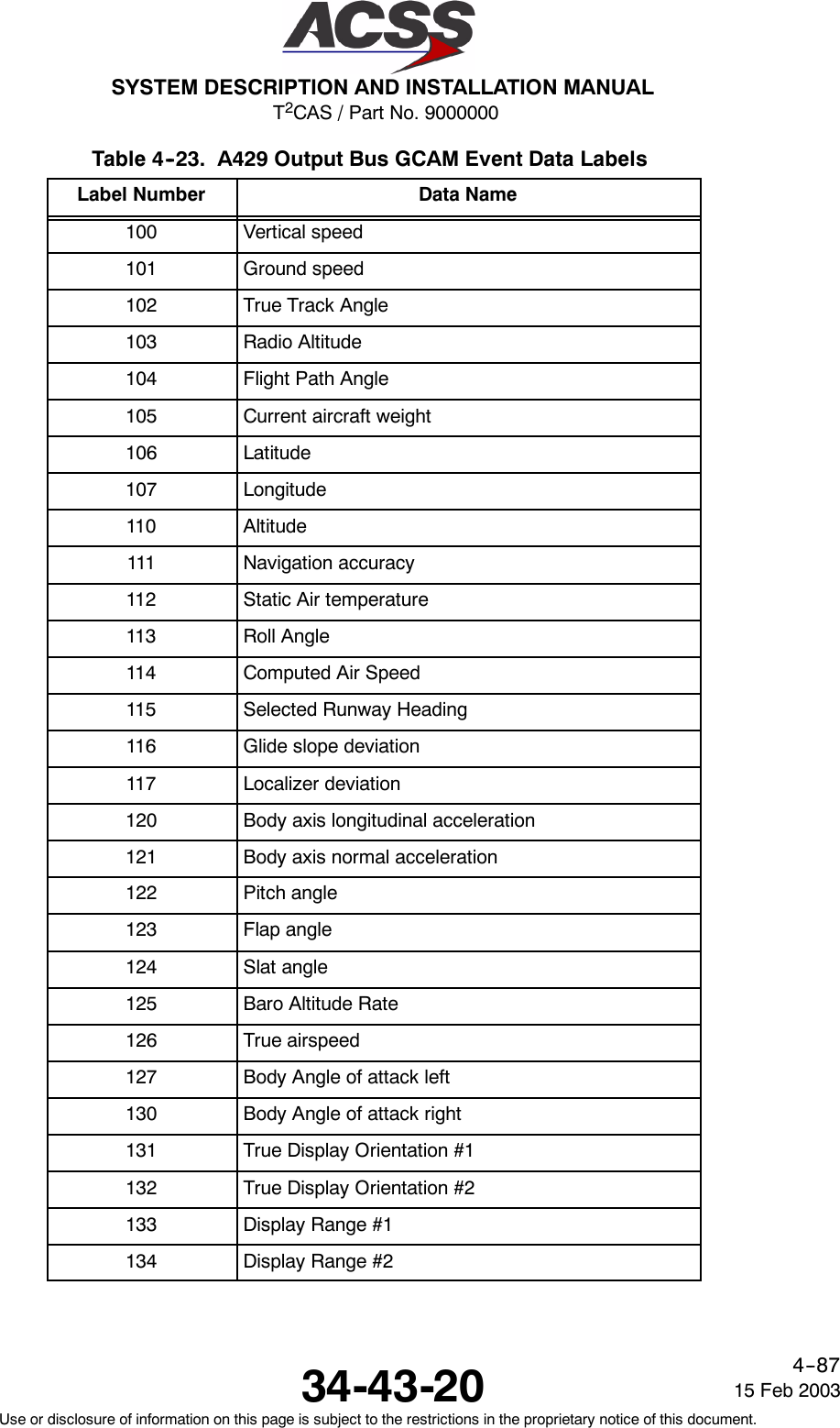
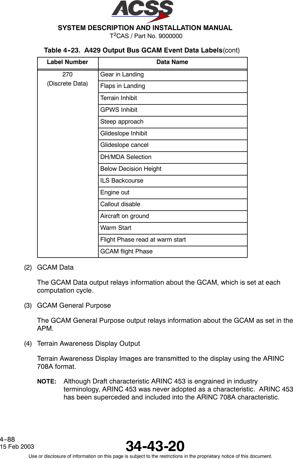
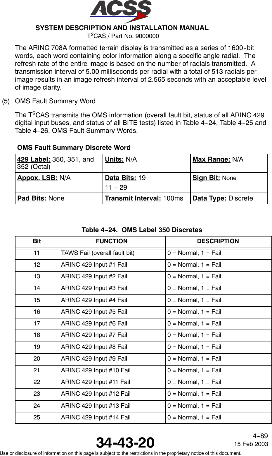
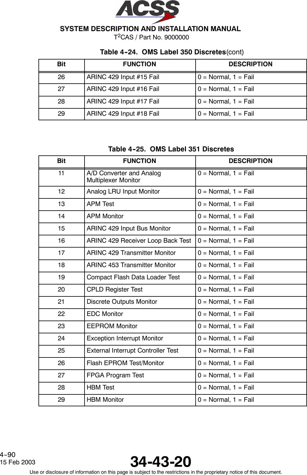
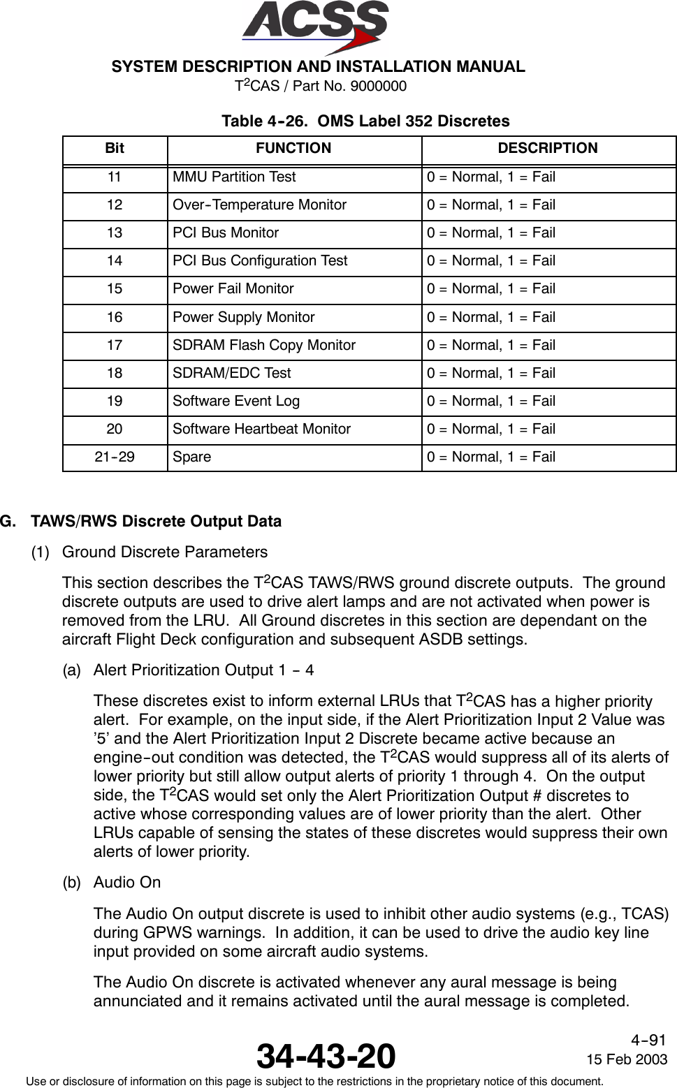
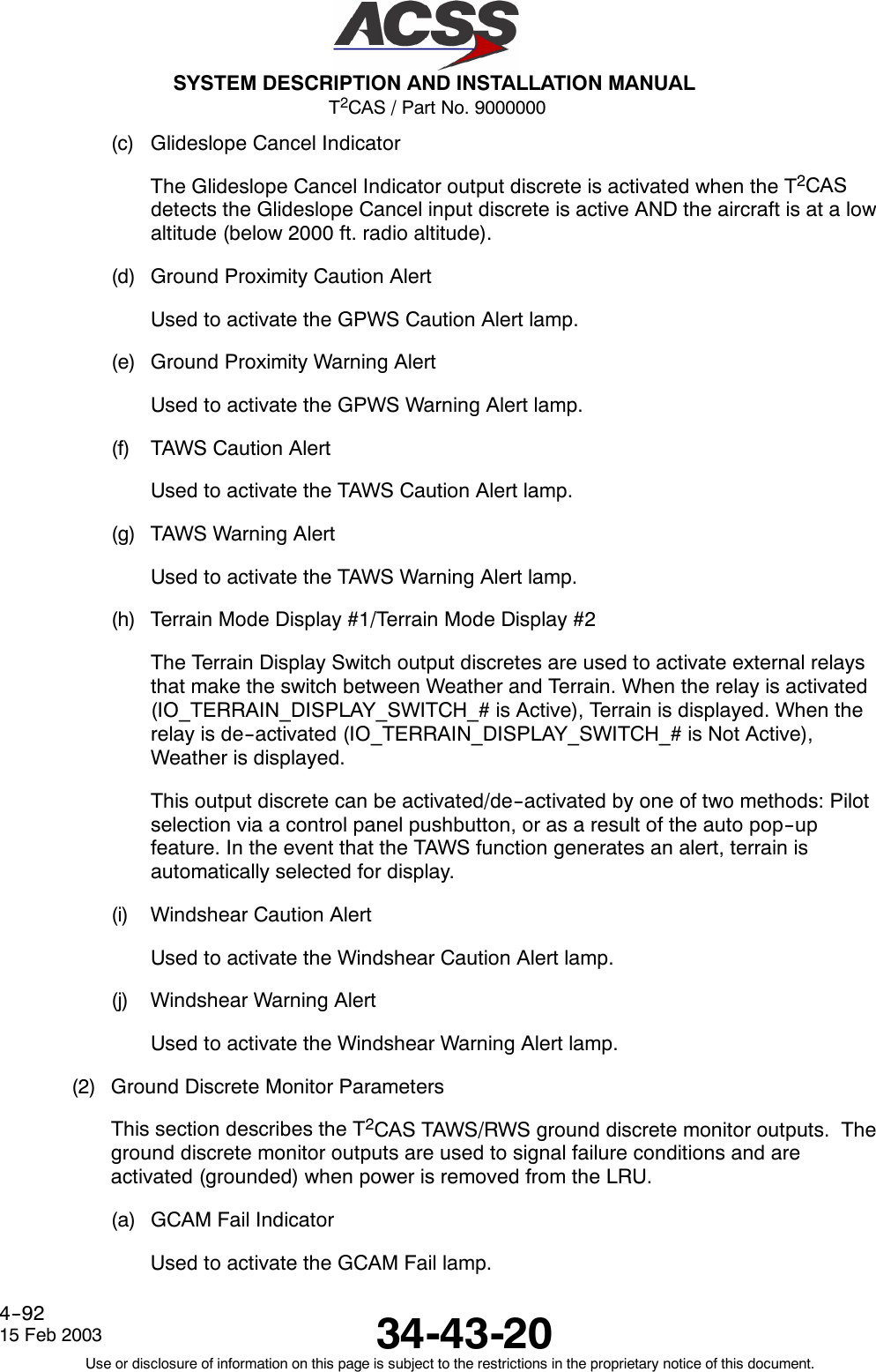
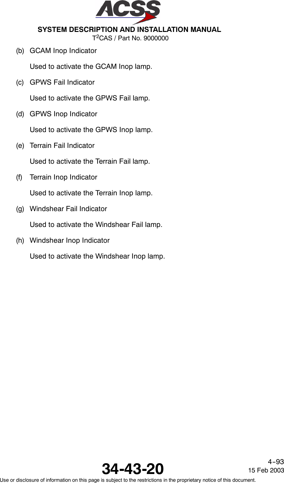

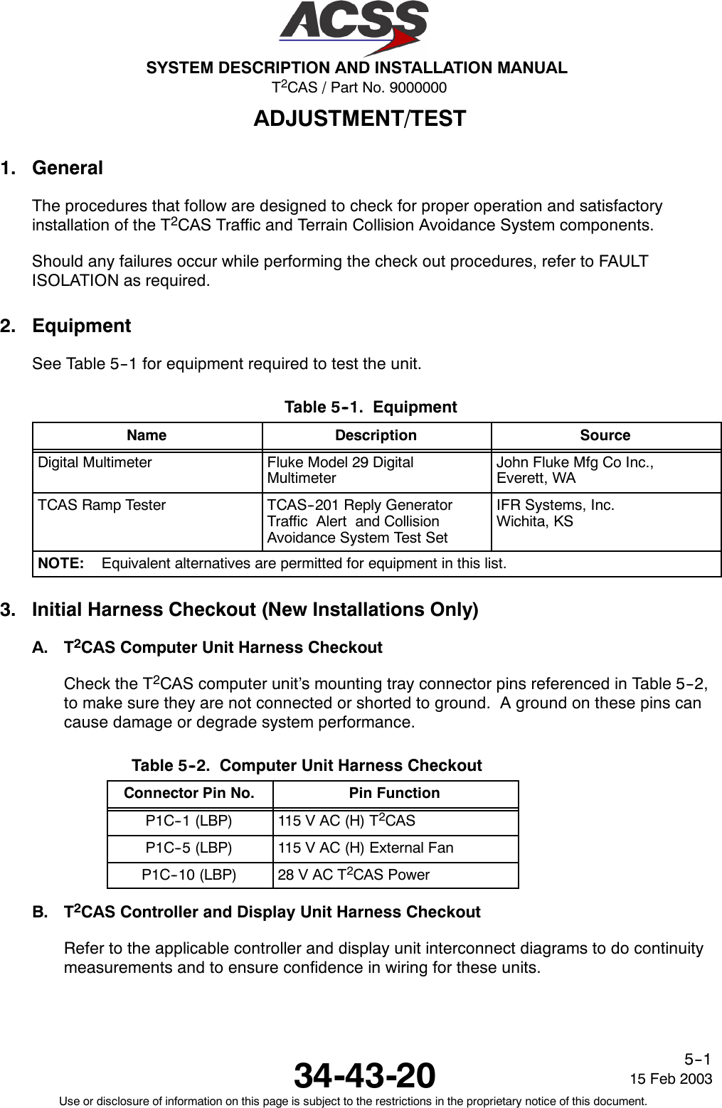
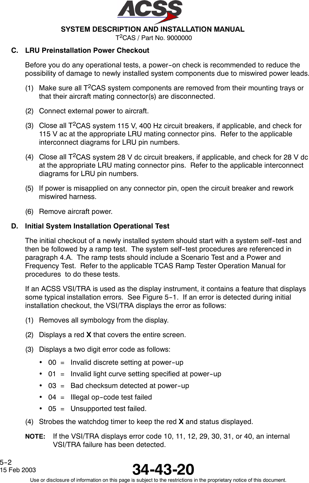
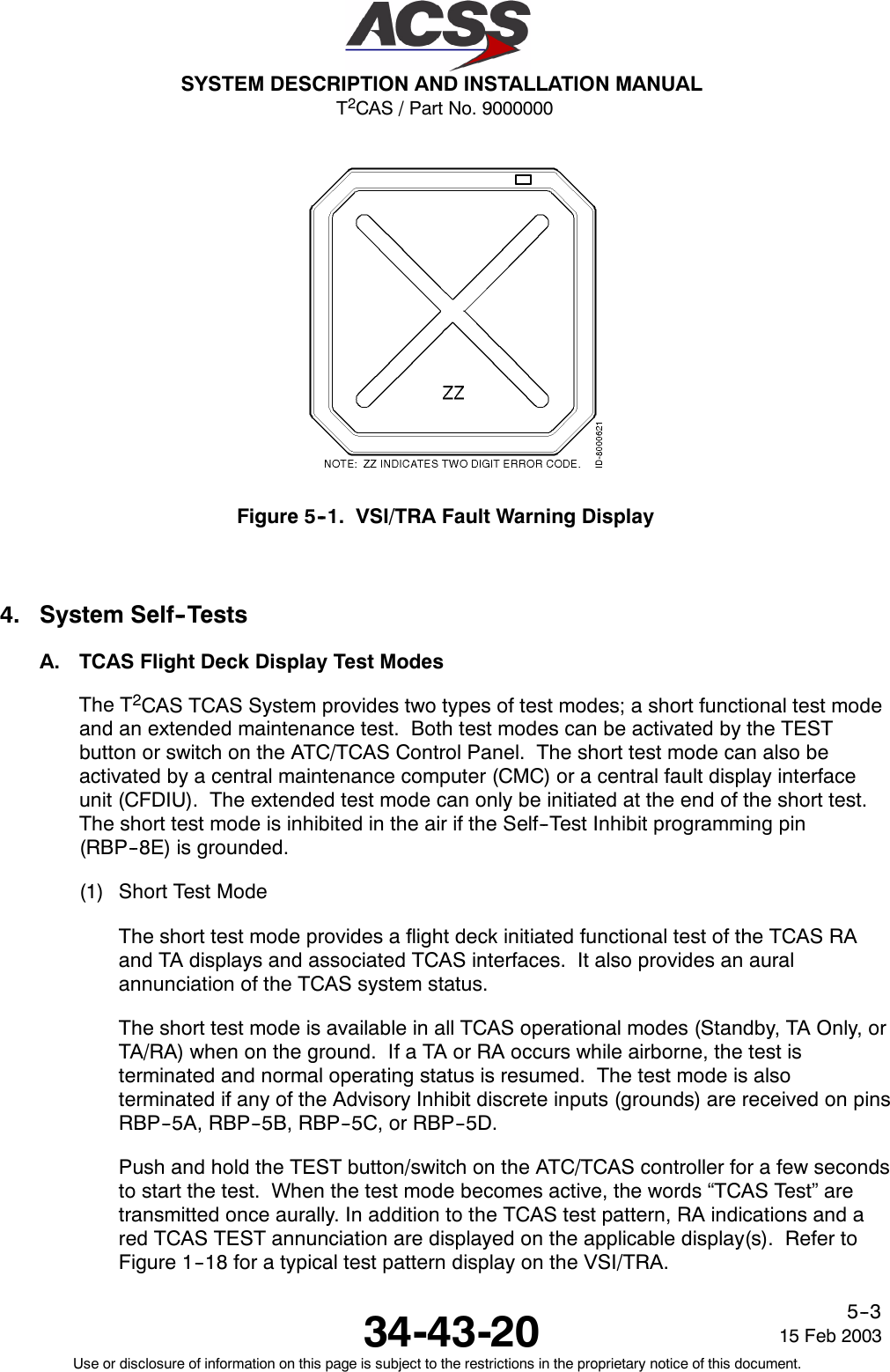
![T2CAS / Part No. 9000000SYSTEM DESCRIPTION AND INSTALLATION MANUAL34-43-2015 Feb 2003Use or disclosure of information on this page is subject to the restrictions in the proprietary notice of this document.5--4At the completion of the test (8--seconds), the words “TCAS Test Pass” should betransmitted once aurally. In addition, the test pattern is removed from the display(s)and a TCAS PASS annunciation is displayed. If the test fails, the words “TCAS TestFail” are transmitted once aurally and a TCAS FAIL annunciation is displayed on theapplicable display(s).If the TCAS short test fails, do the TCAS Computer Unit Self--Test proceduresreferenced in paragraph 4.C. to determine which LRU or subsystem is not functioningproperly. To troubleshoot the system, refer to the procedures in the FAULTISOLATION section.(2) Extended Test ModeThe extended test mode provides a flight deck initiated test that displays variouspages of text information that is selected by the ATC Mode S control panel 4096code switches. This test mode is accessible only when on the ground and cannot beinitiated while airborne.The extended test mode is used for maintenance purposes only. It displays variouspages of text information containing the TCAS software part number, fault messages,status of program pins, analog and digital inputs, and other aircraft parameters.To start the test, push and hold the TEST button/switch on the ATC/TCAS controllerfor a minimum of 9 seconds. In addition the conditions that follow must occur:•TCAS is in Standby•The selected transponder is in Standby•Aircraft is on the ground (The AIR/GND discrete [RMP--5K] is grounded)•Landing gear is extended (Landing Gear discrete [RMP--13F] is grounded).Once the extended test mode is established, the 4096 code switches on theATC/TCAS controller are used to select the desired maintenance page for display.Table 5--3 lists the extended mode page names and numbers and the corresponding4096 Ident Code number.](https://usermanual.wiki/ACSS-an-L-3-Communications-and-Thales/TT-950.User-Manual-Part-2/User-Guide-302828-Page-139.png)
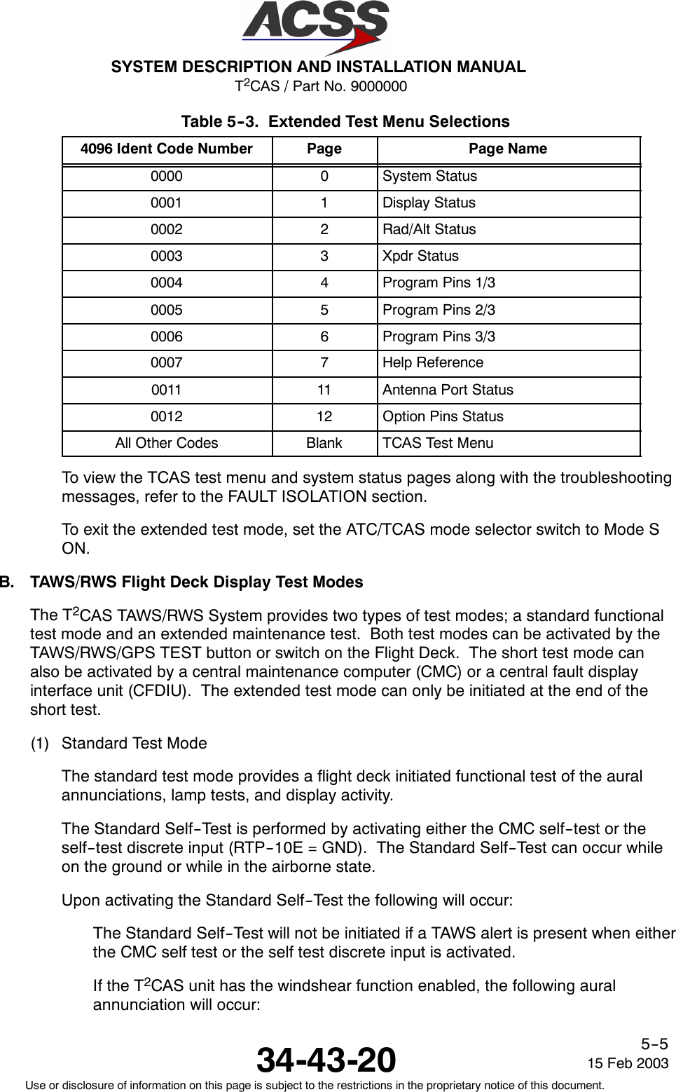
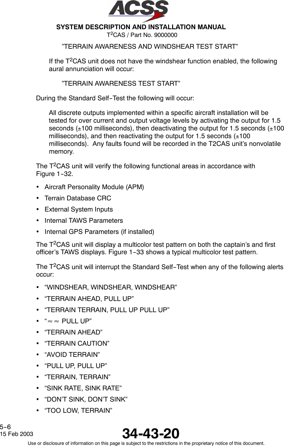
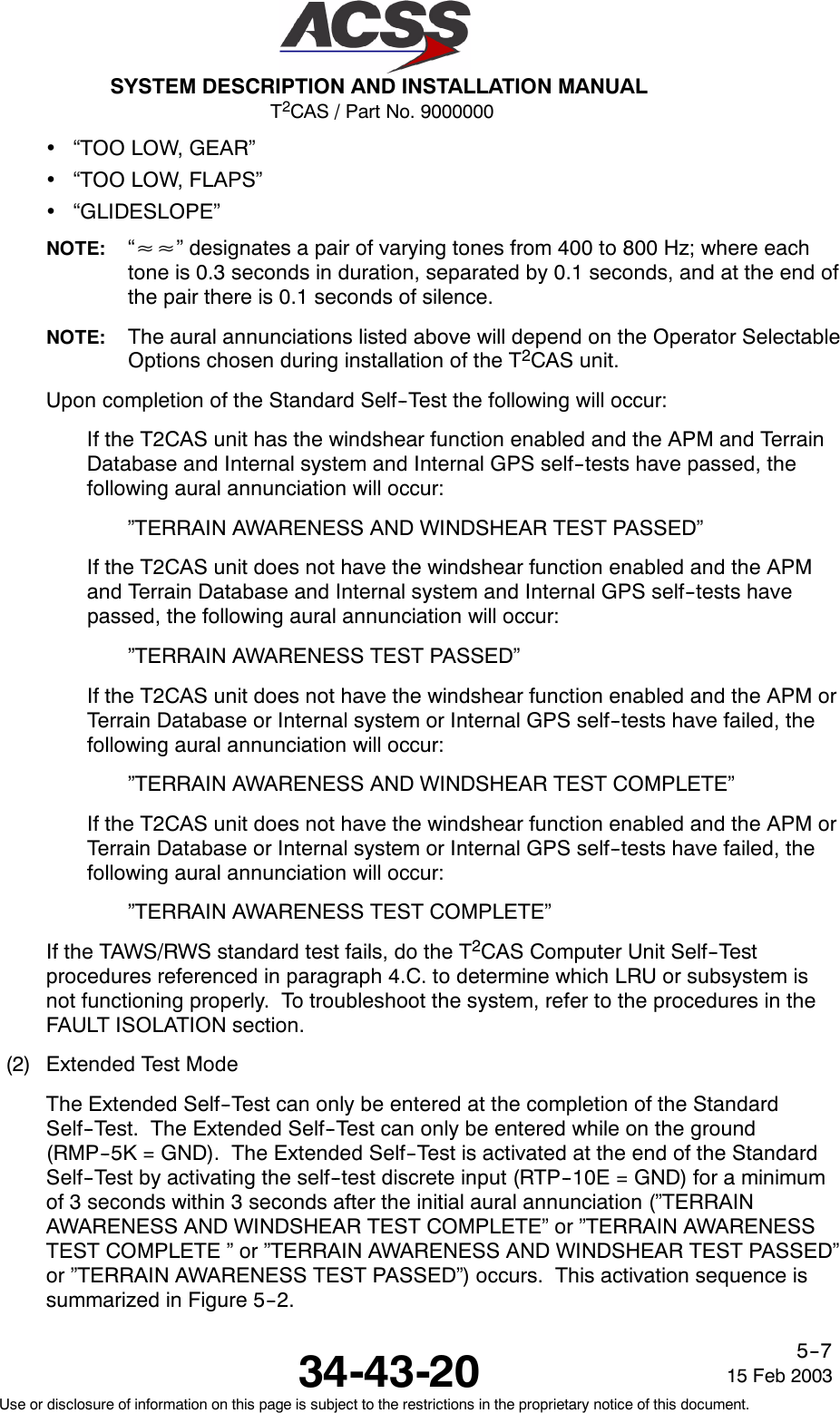
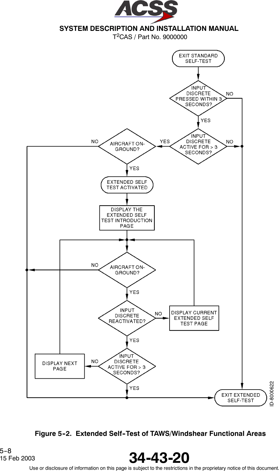
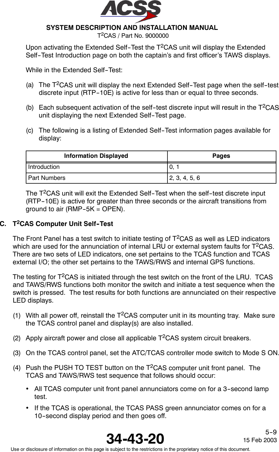
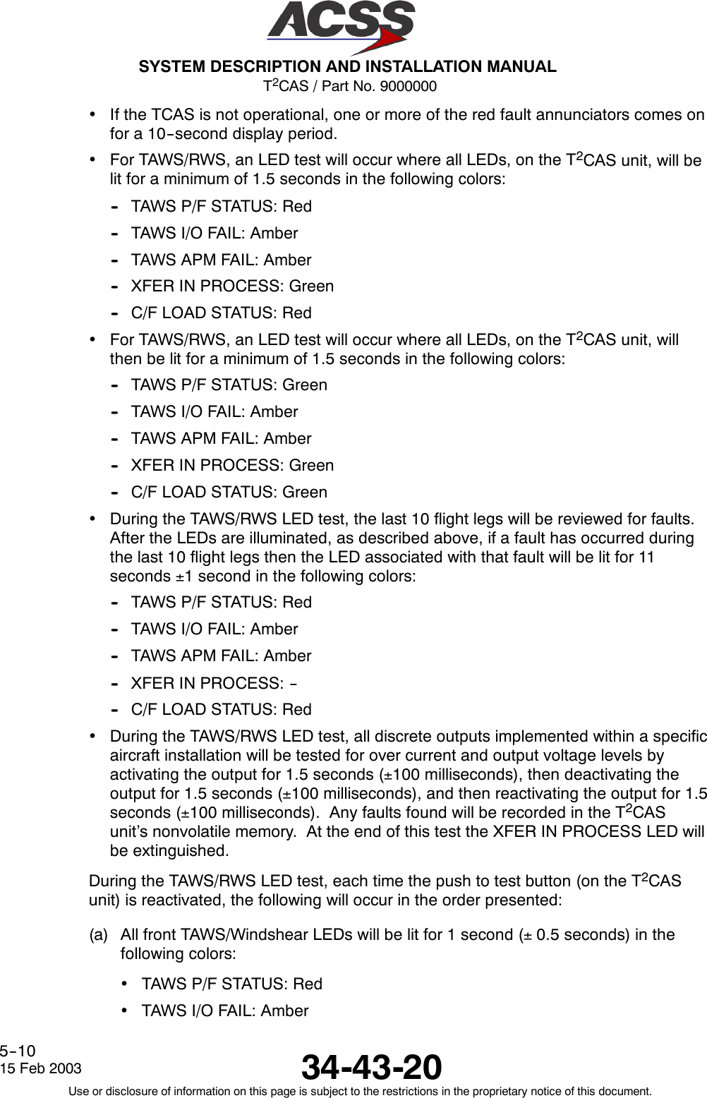
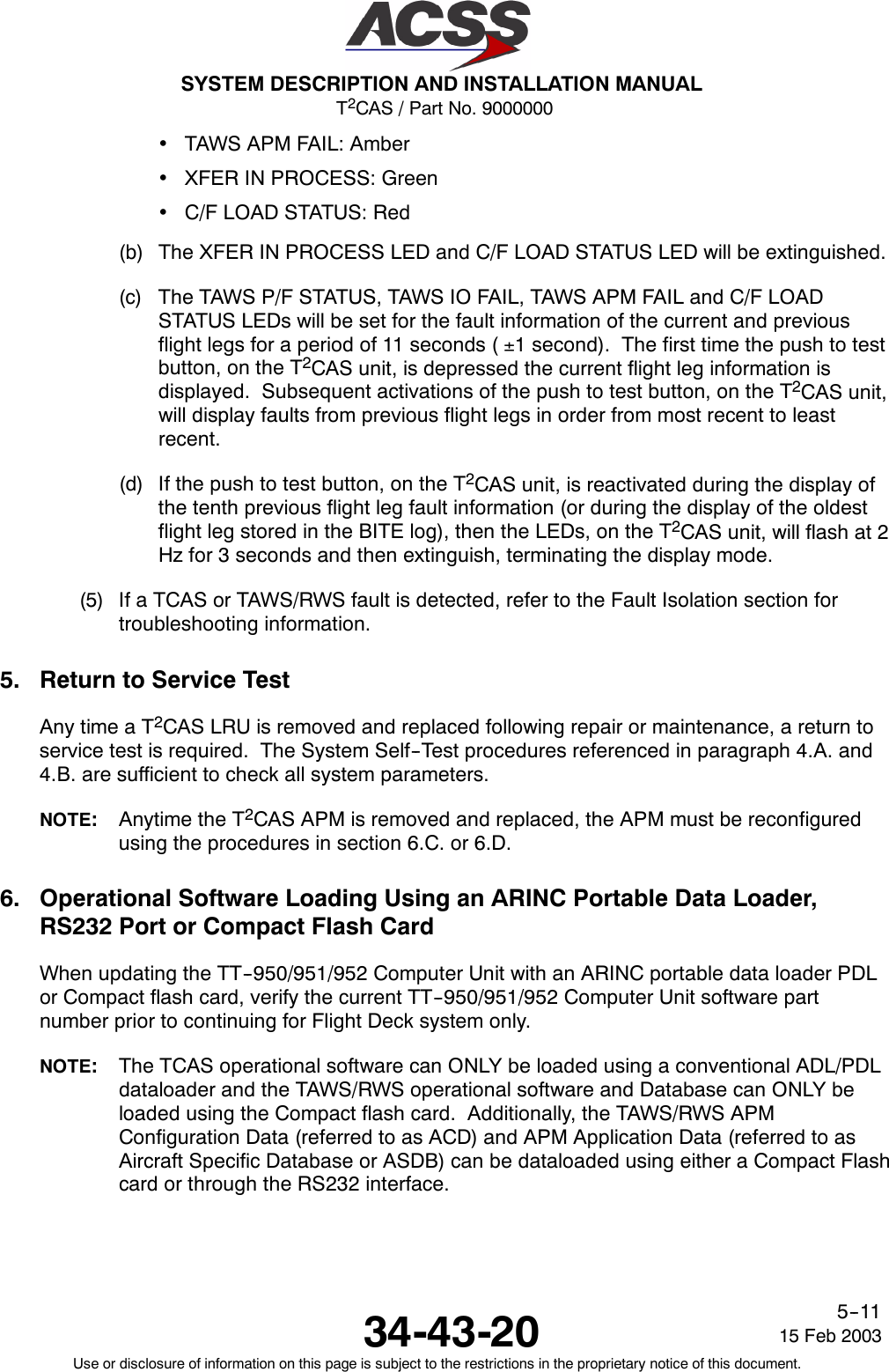
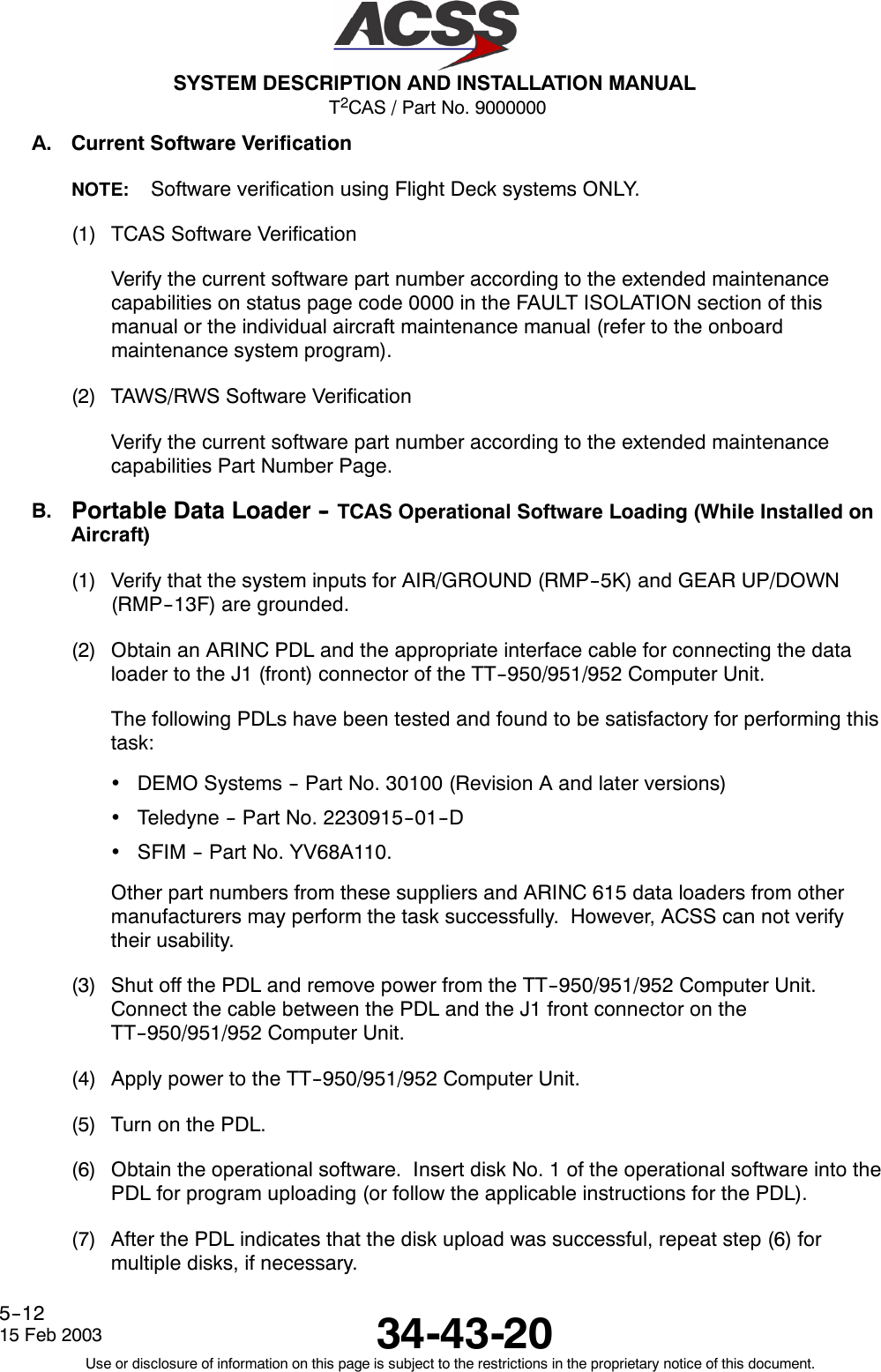
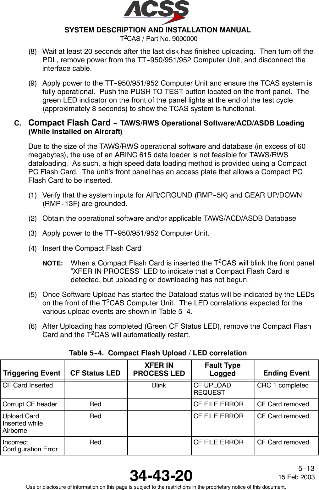
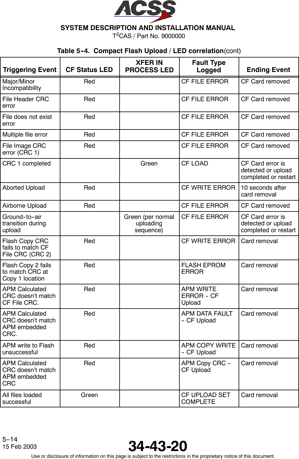
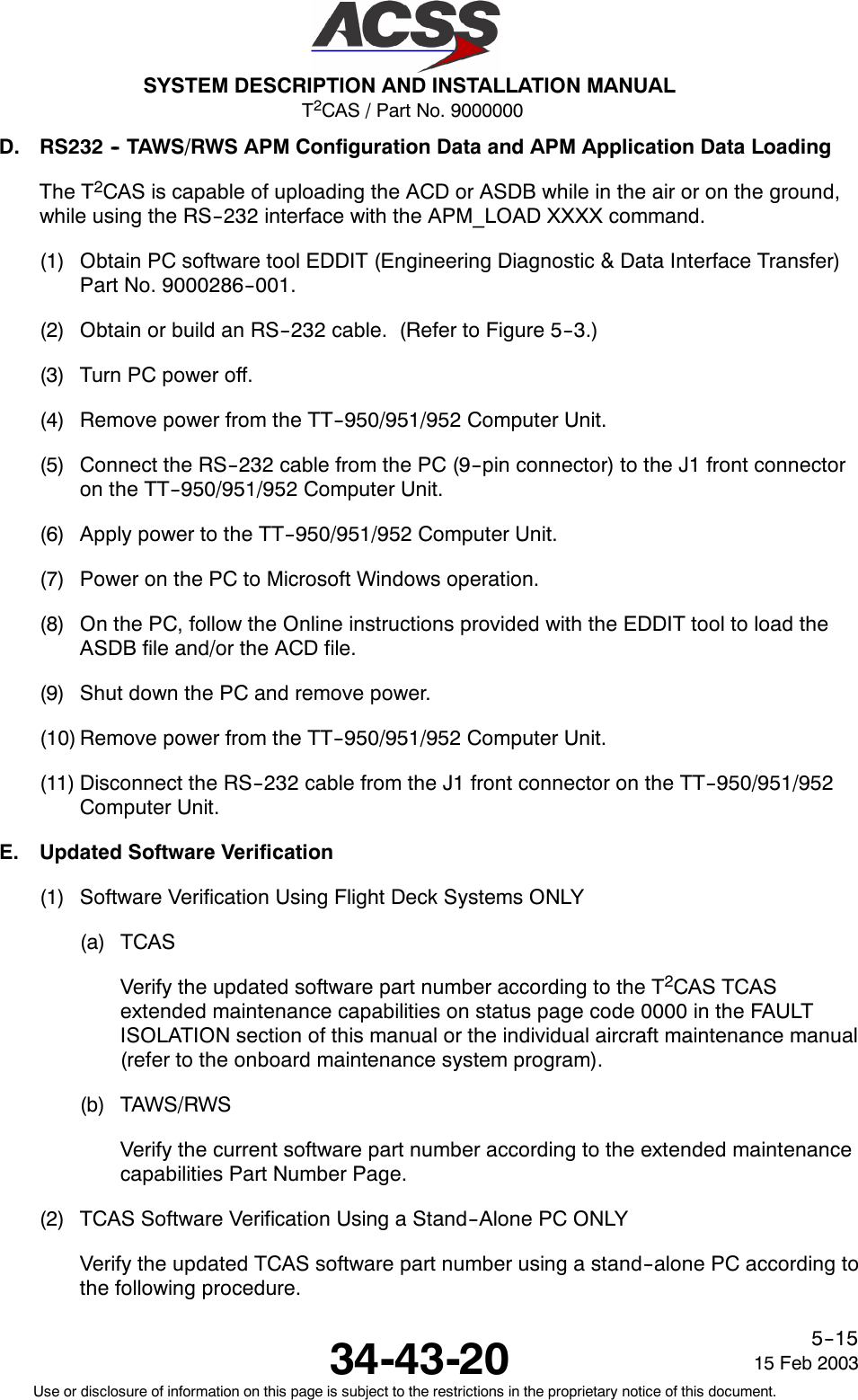
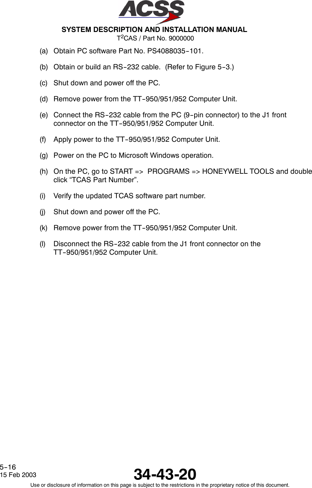
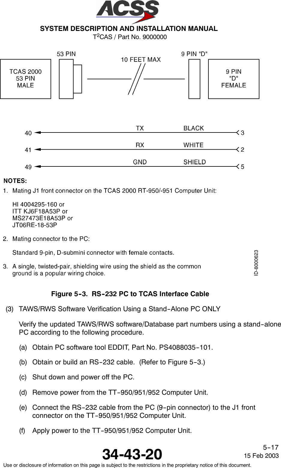
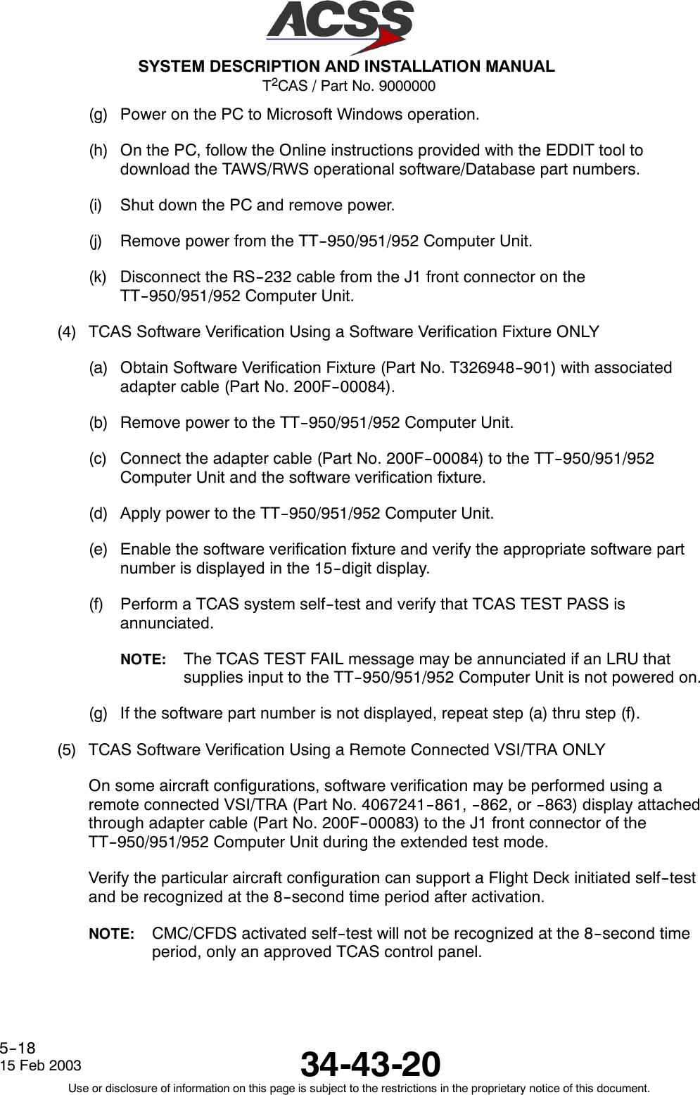
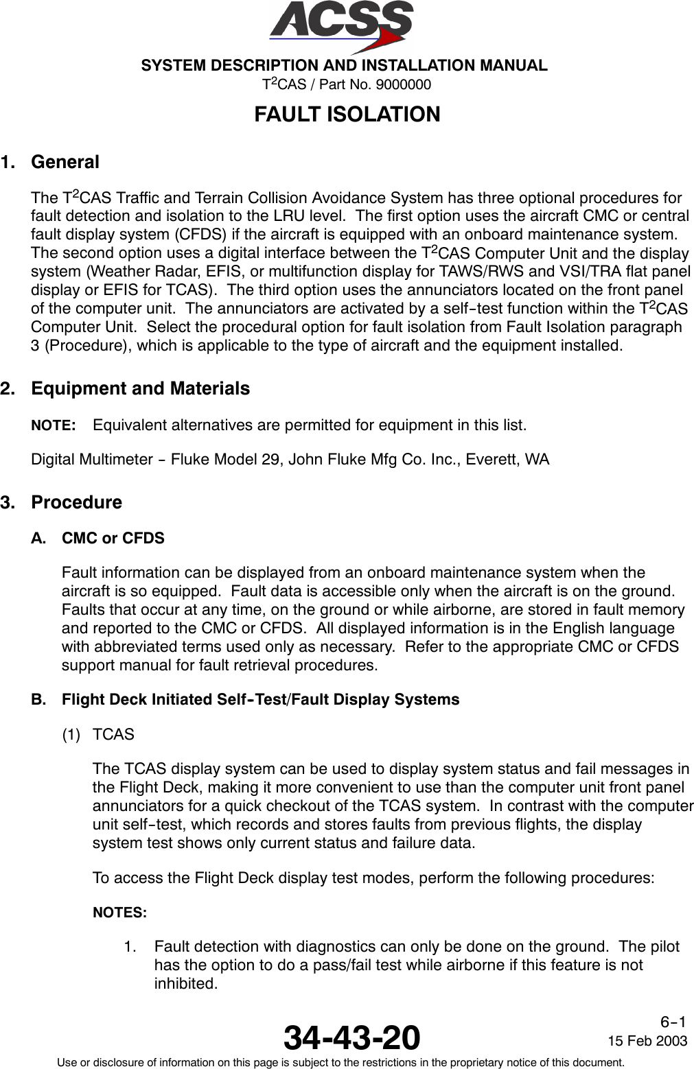
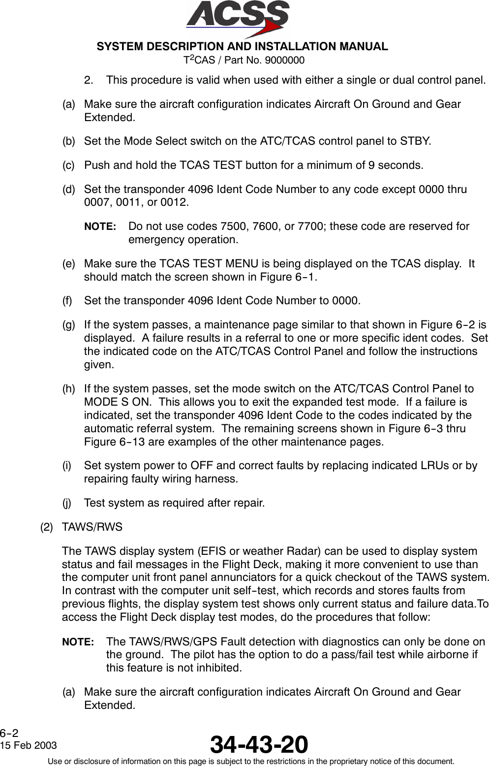
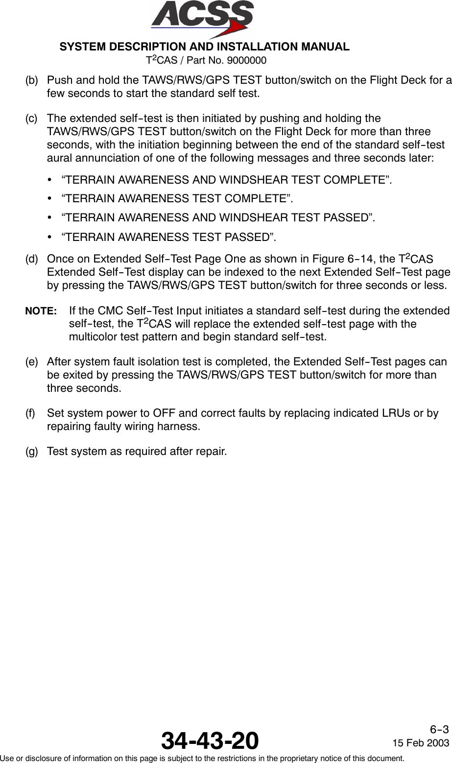
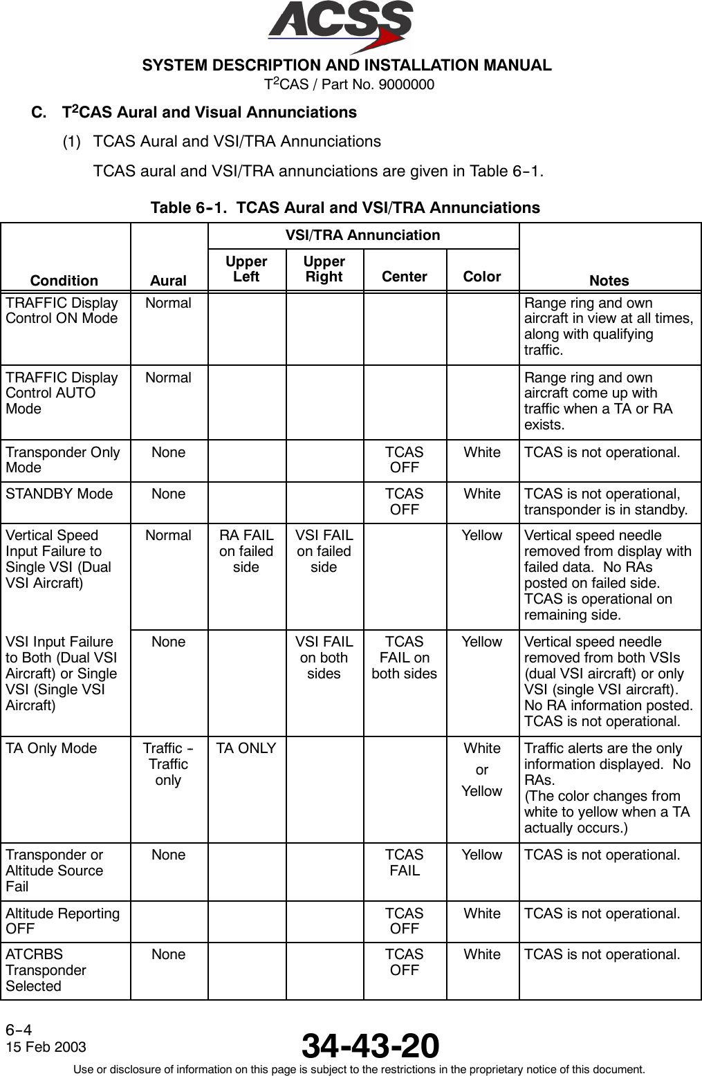
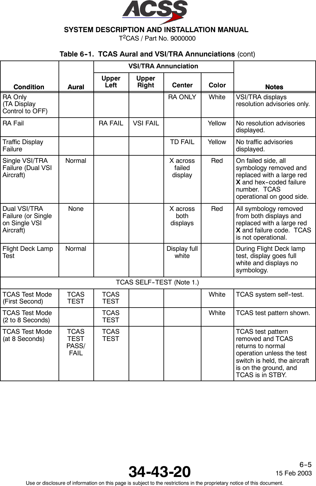
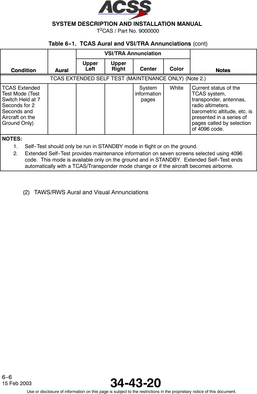
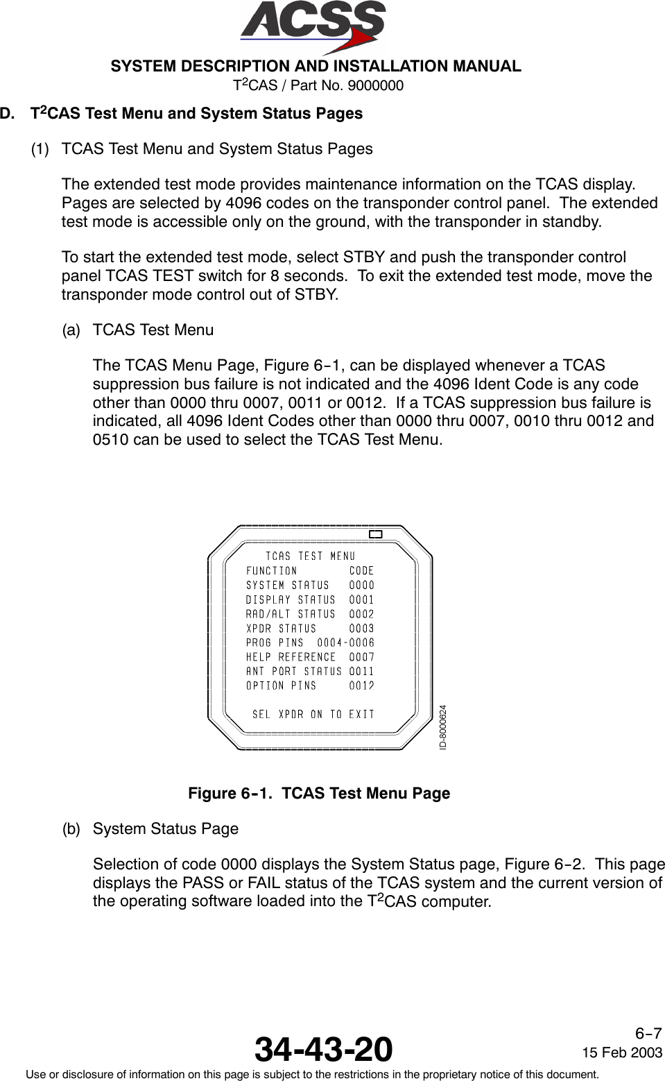
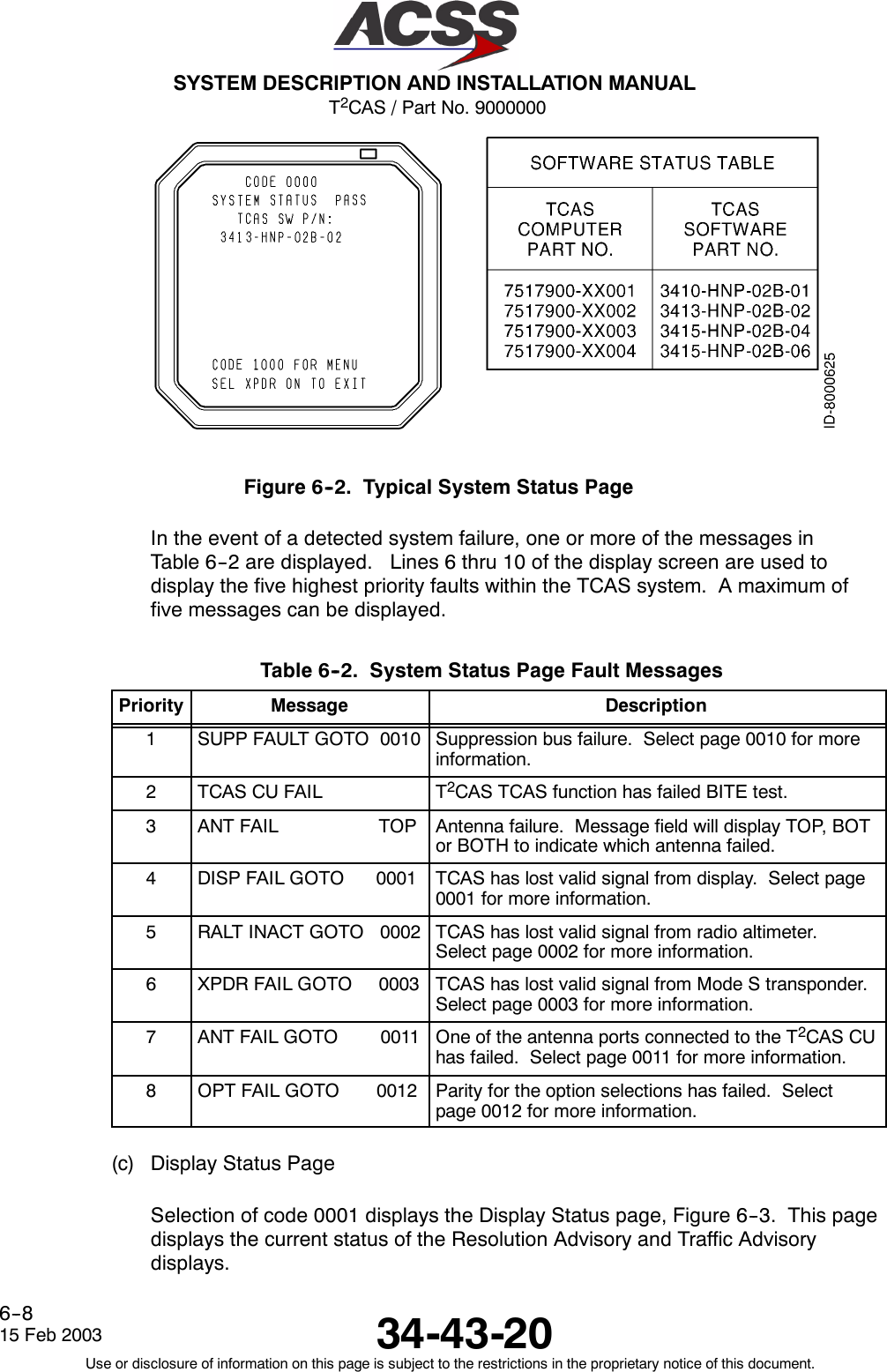
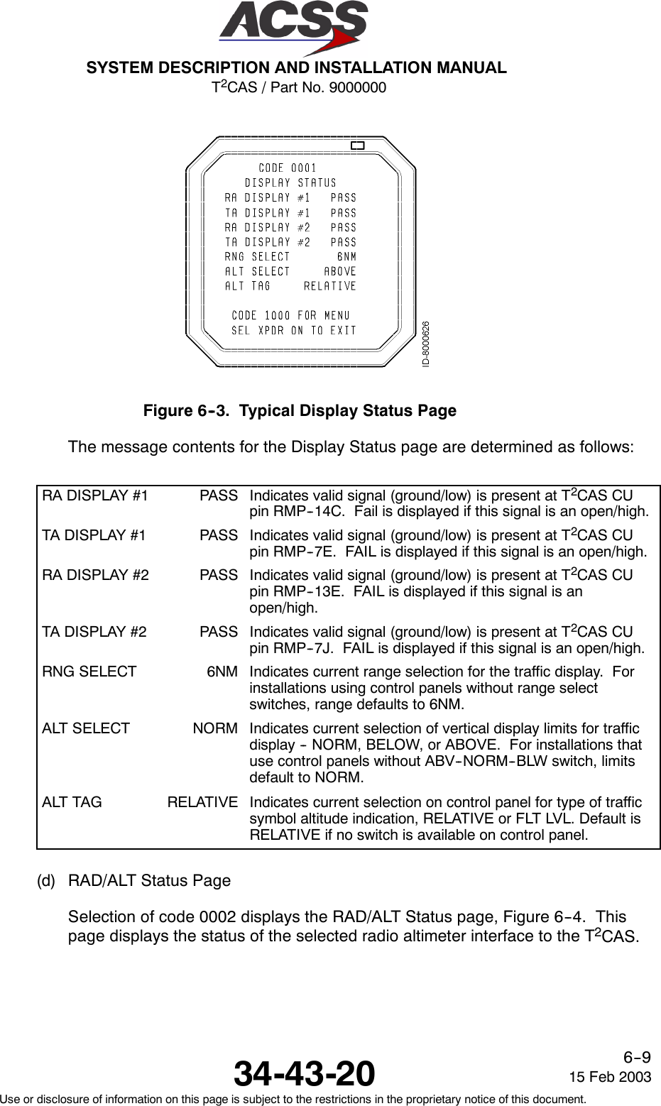
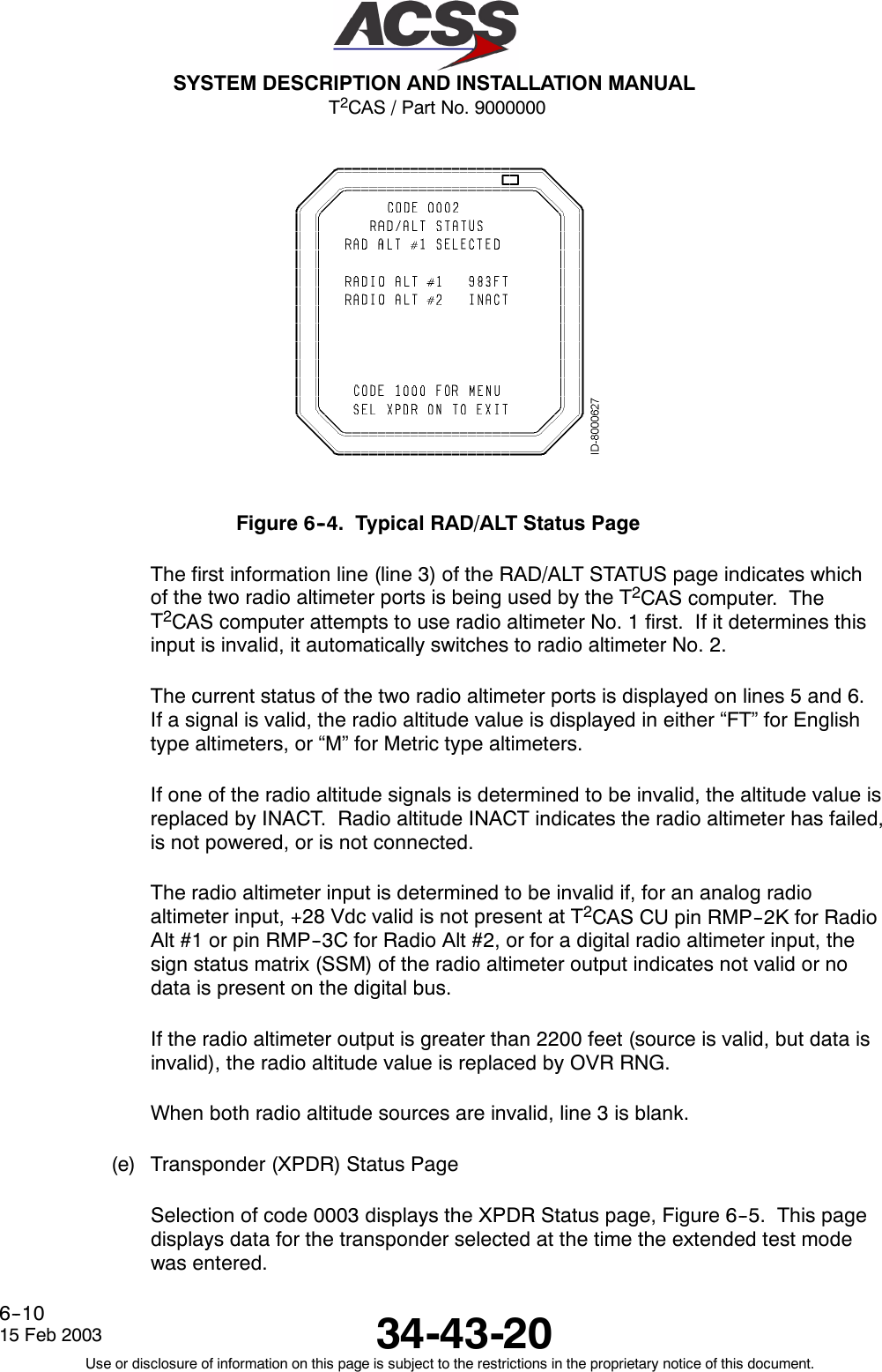
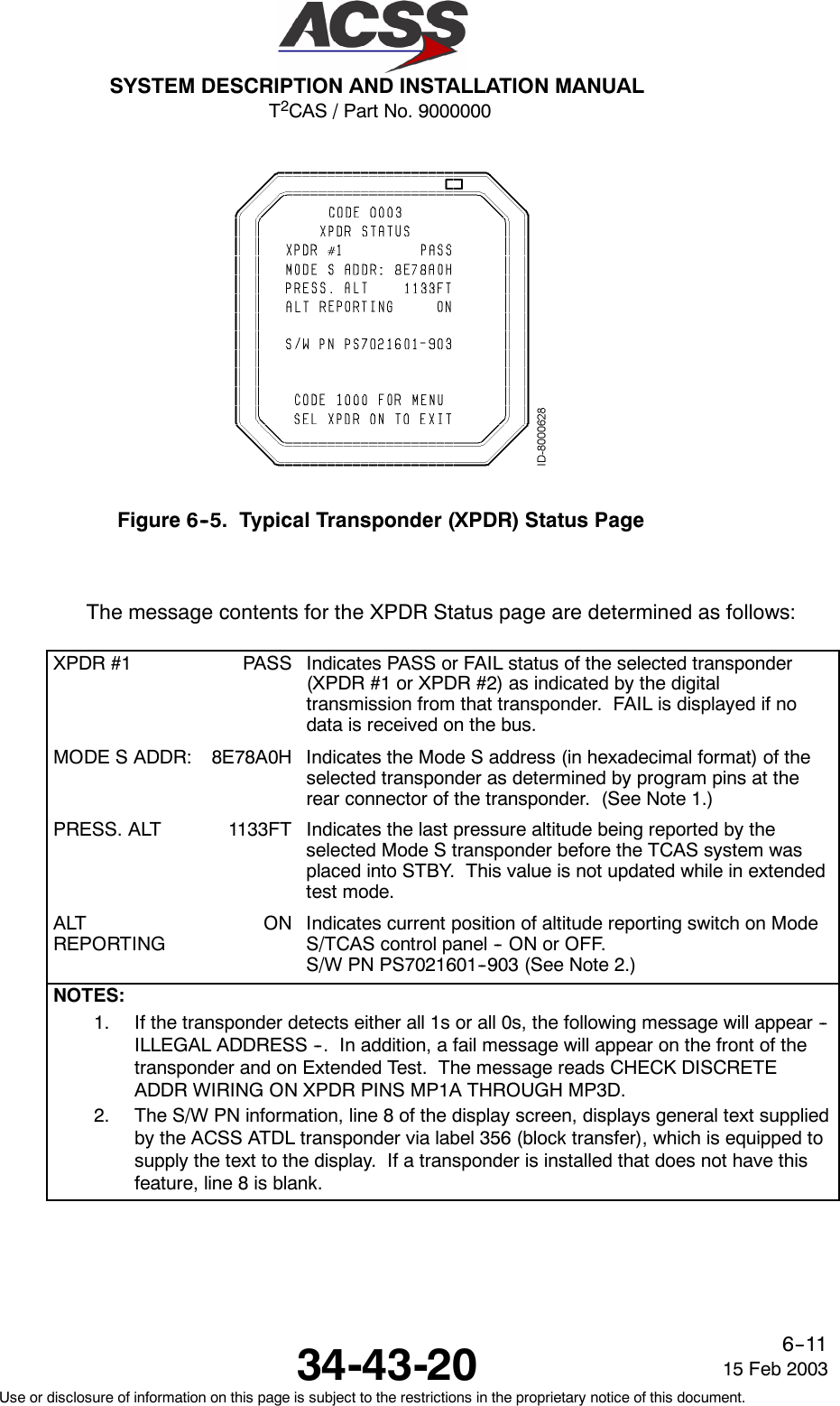
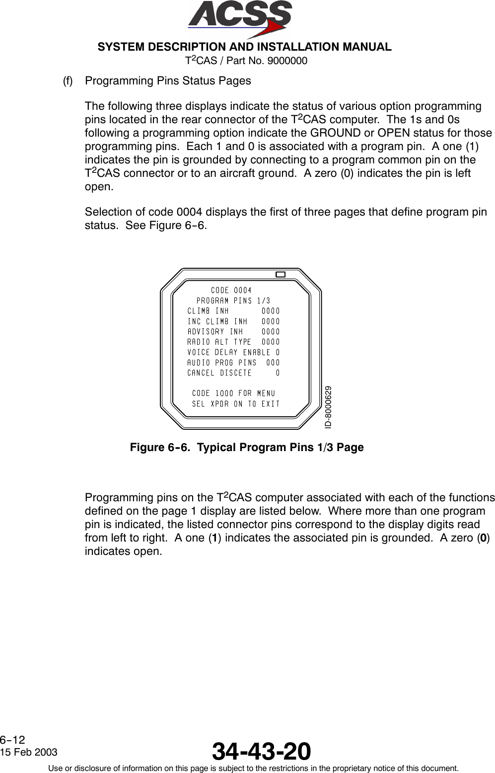
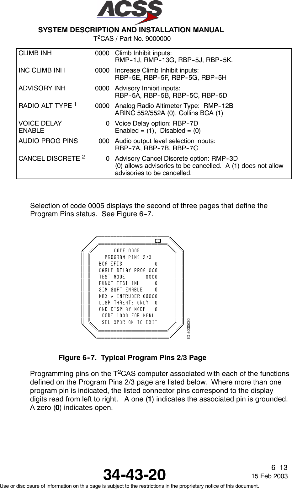
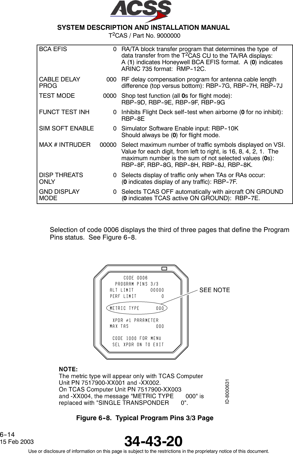
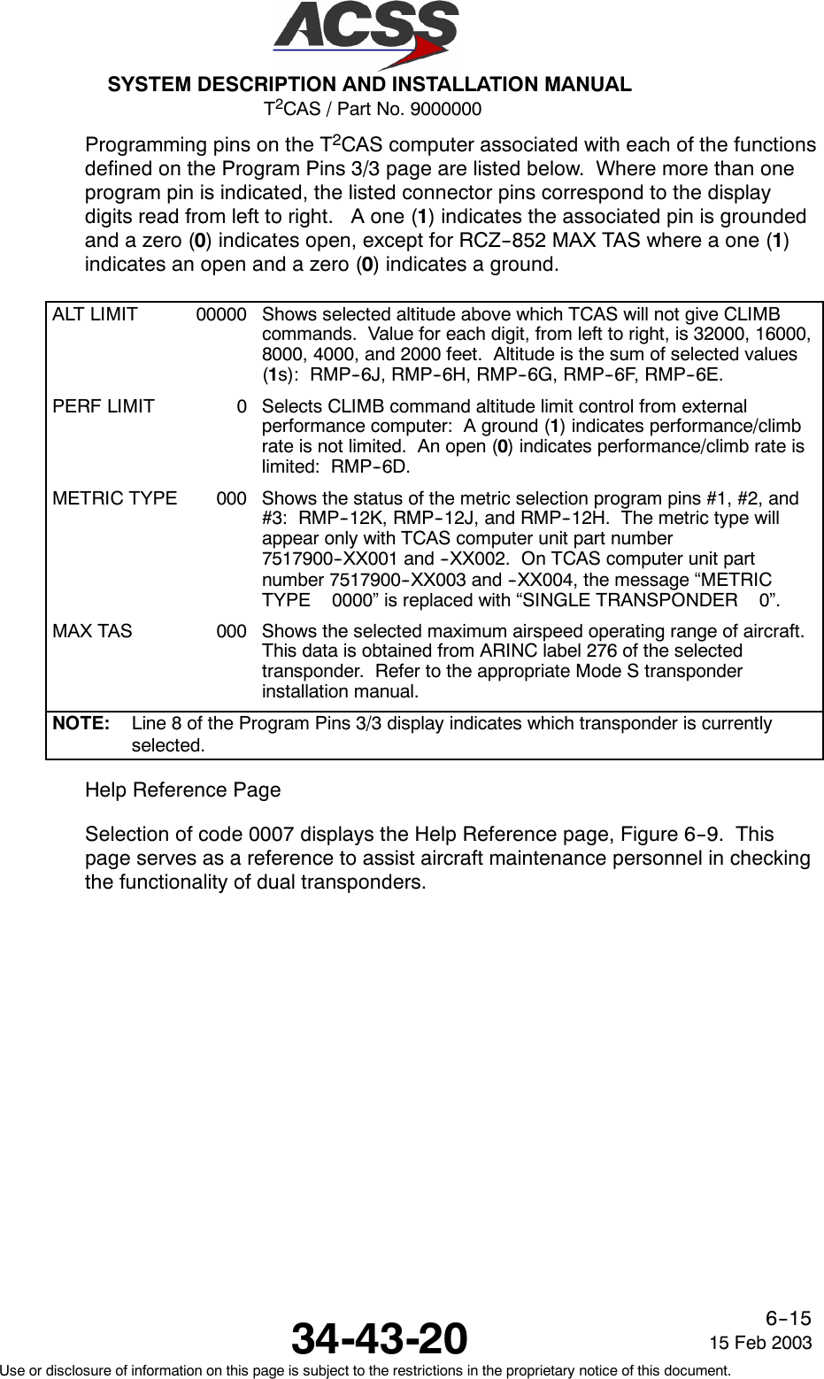
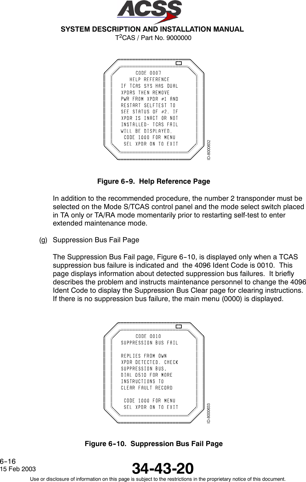
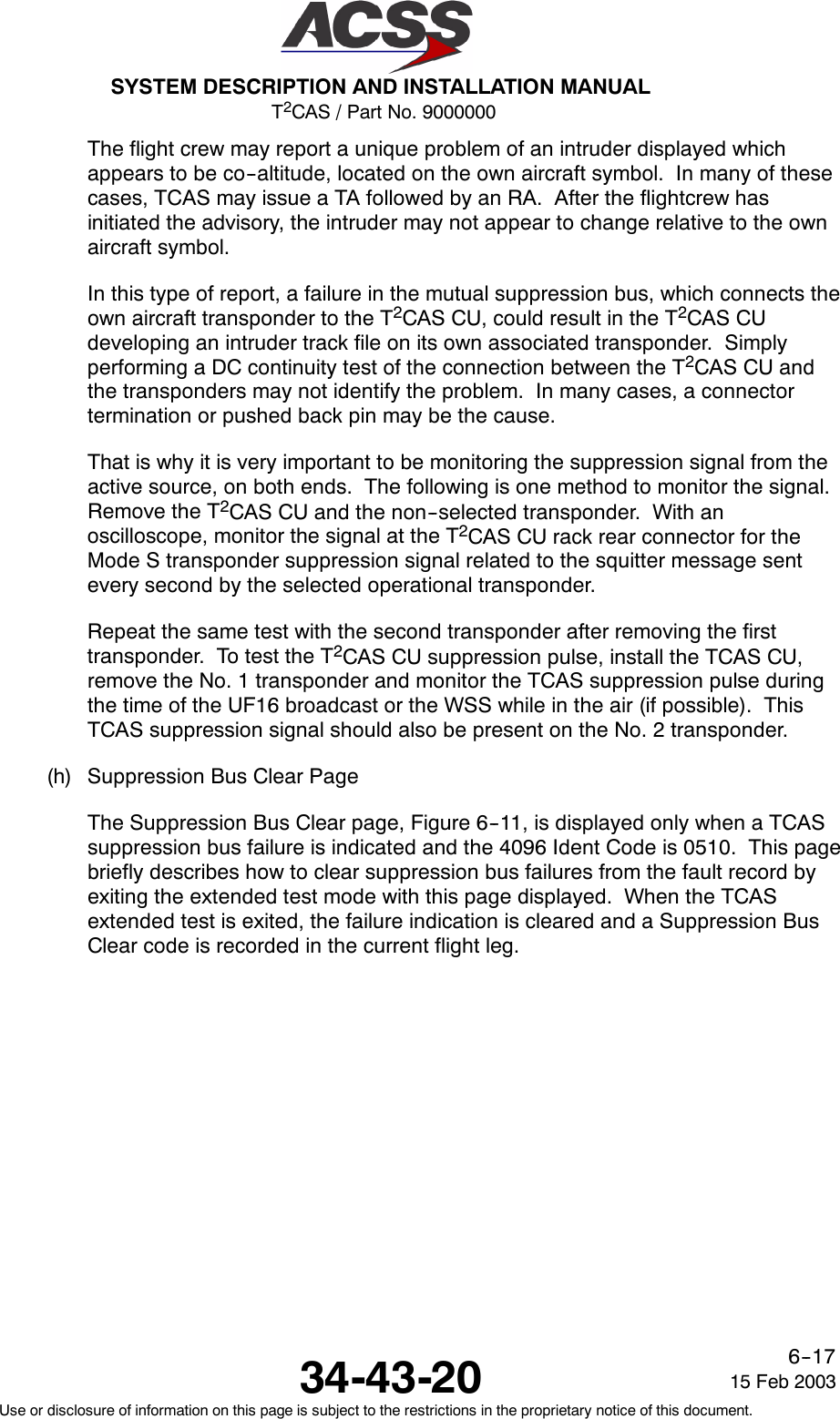
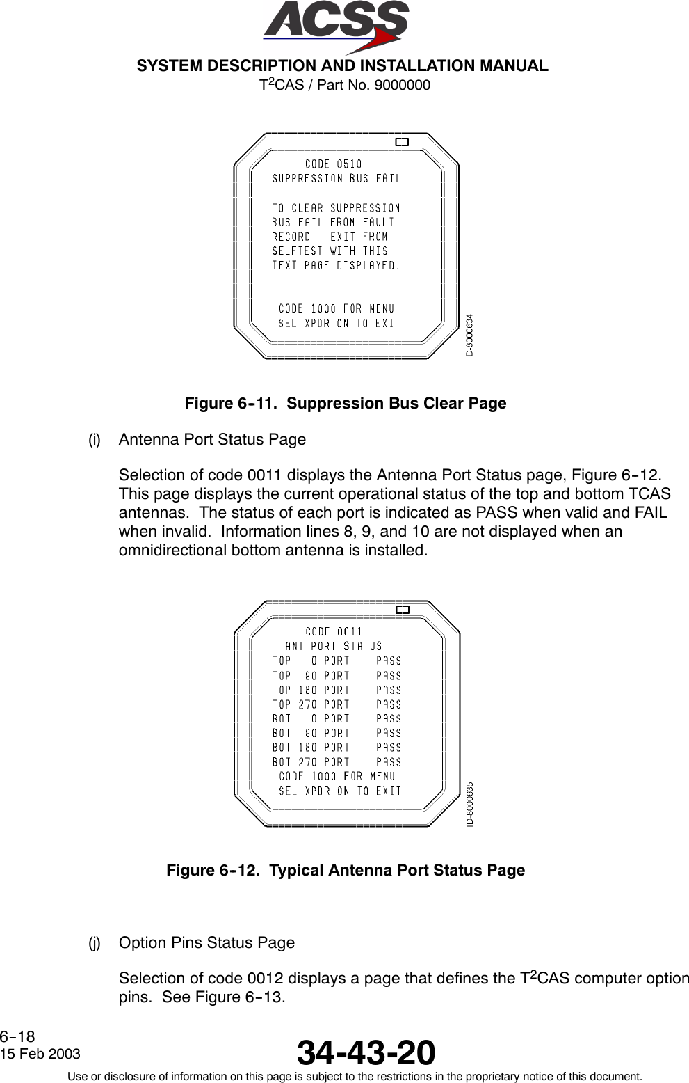
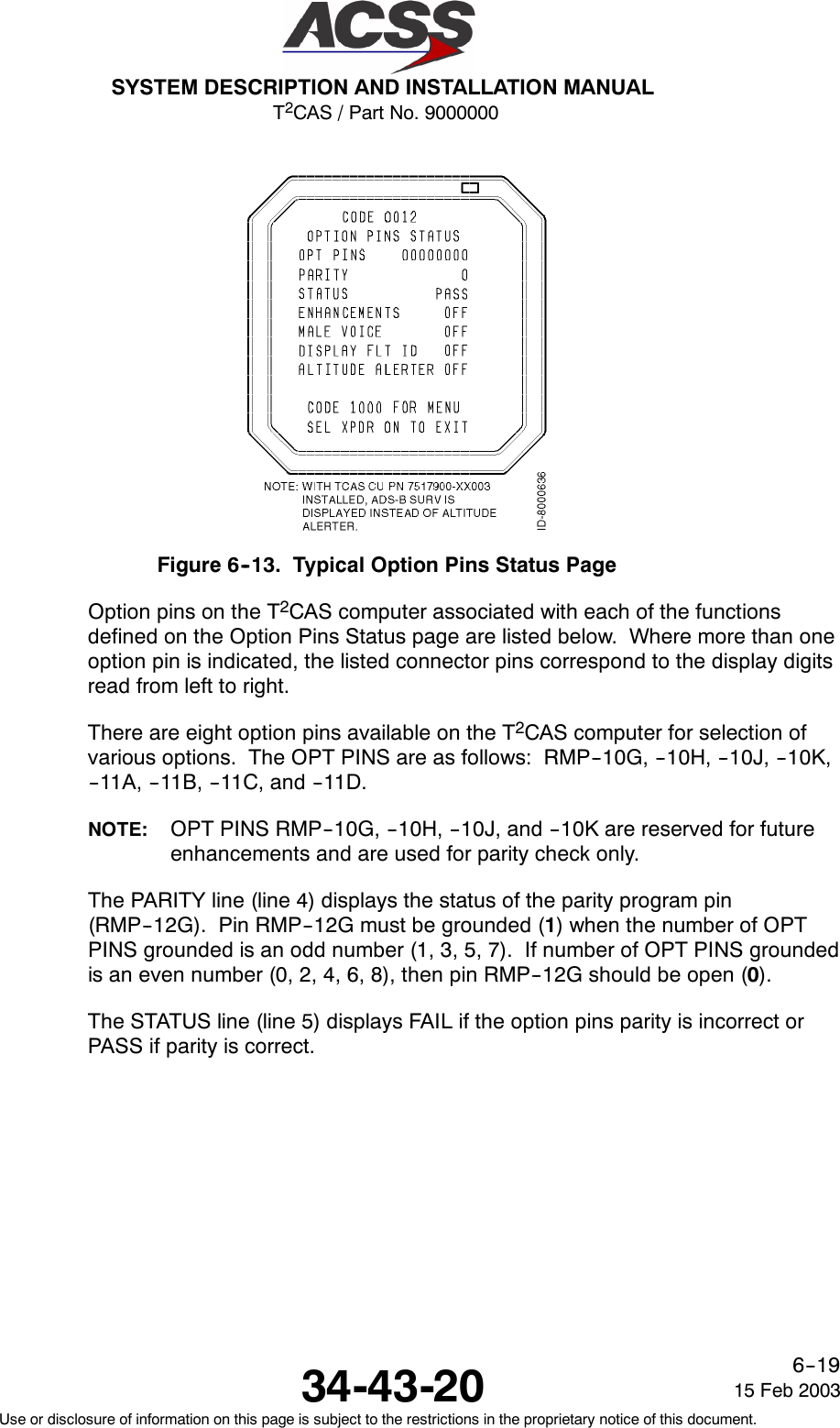
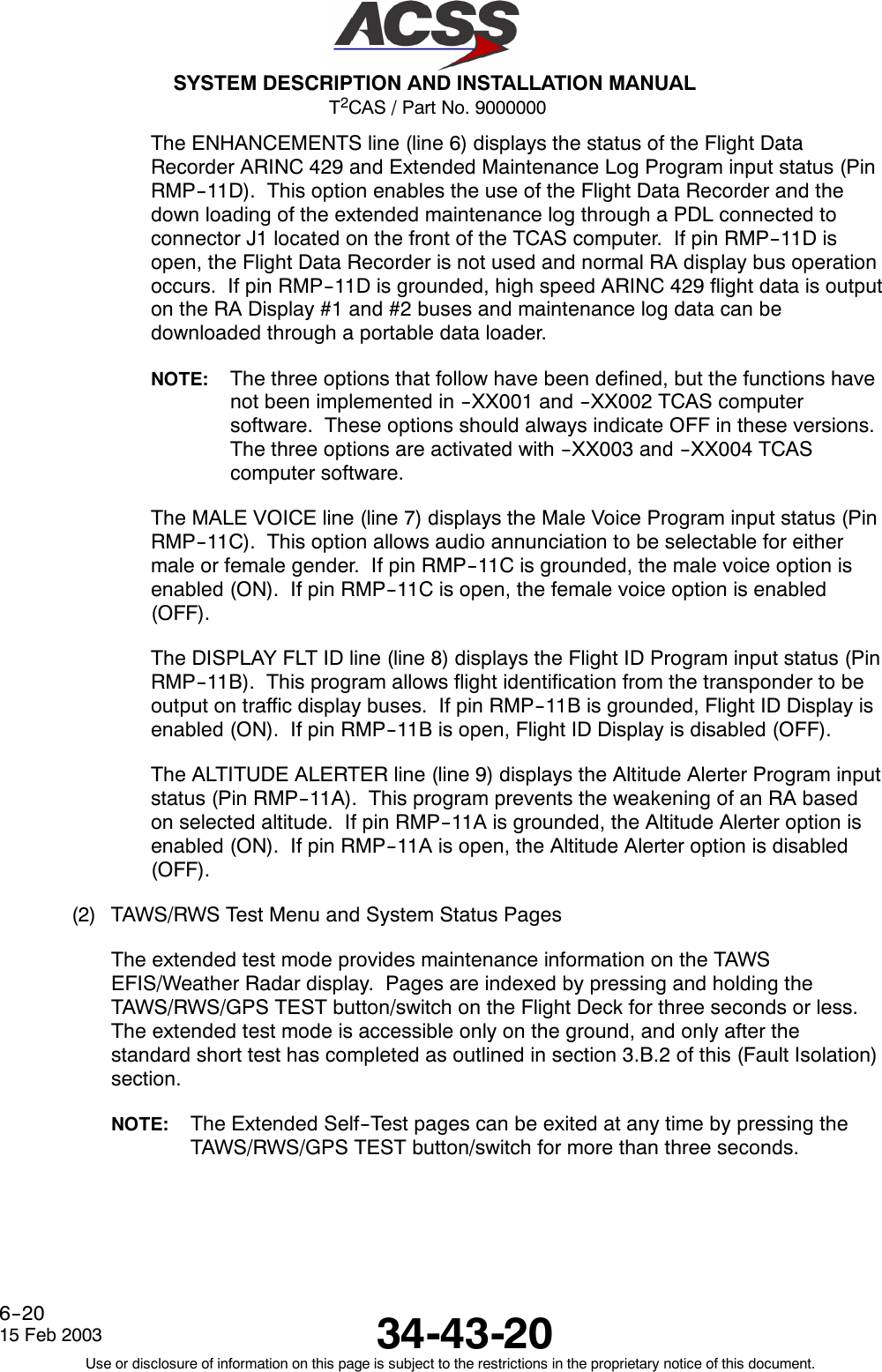

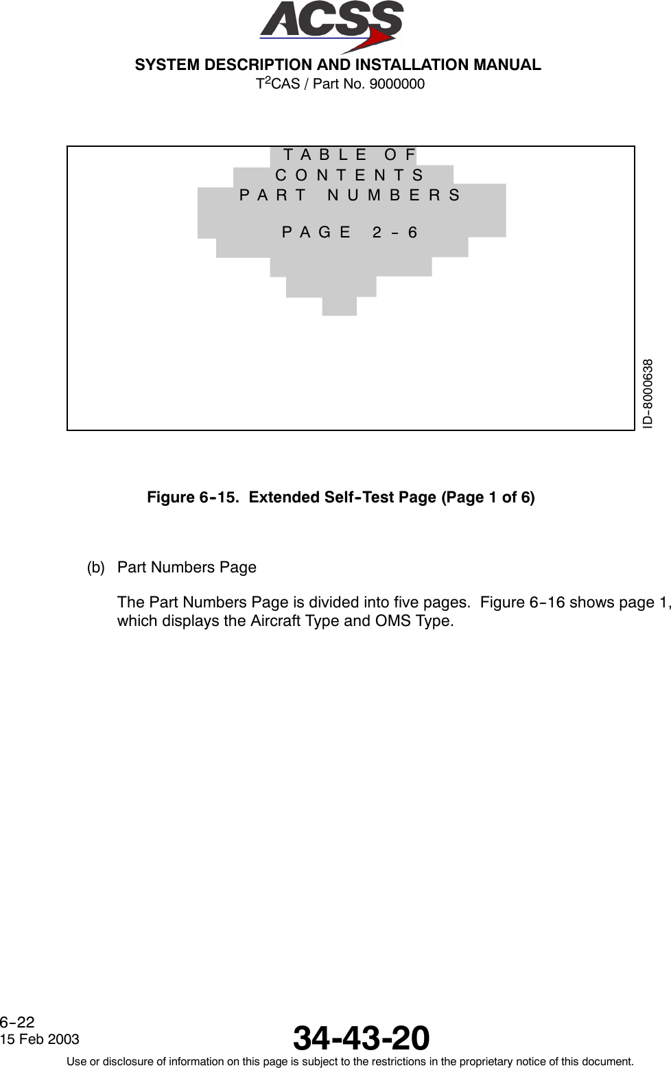
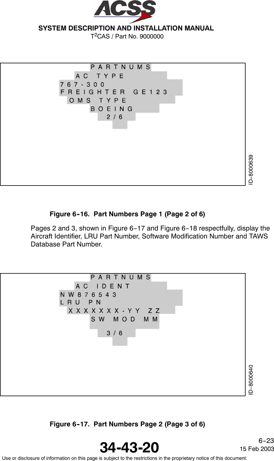
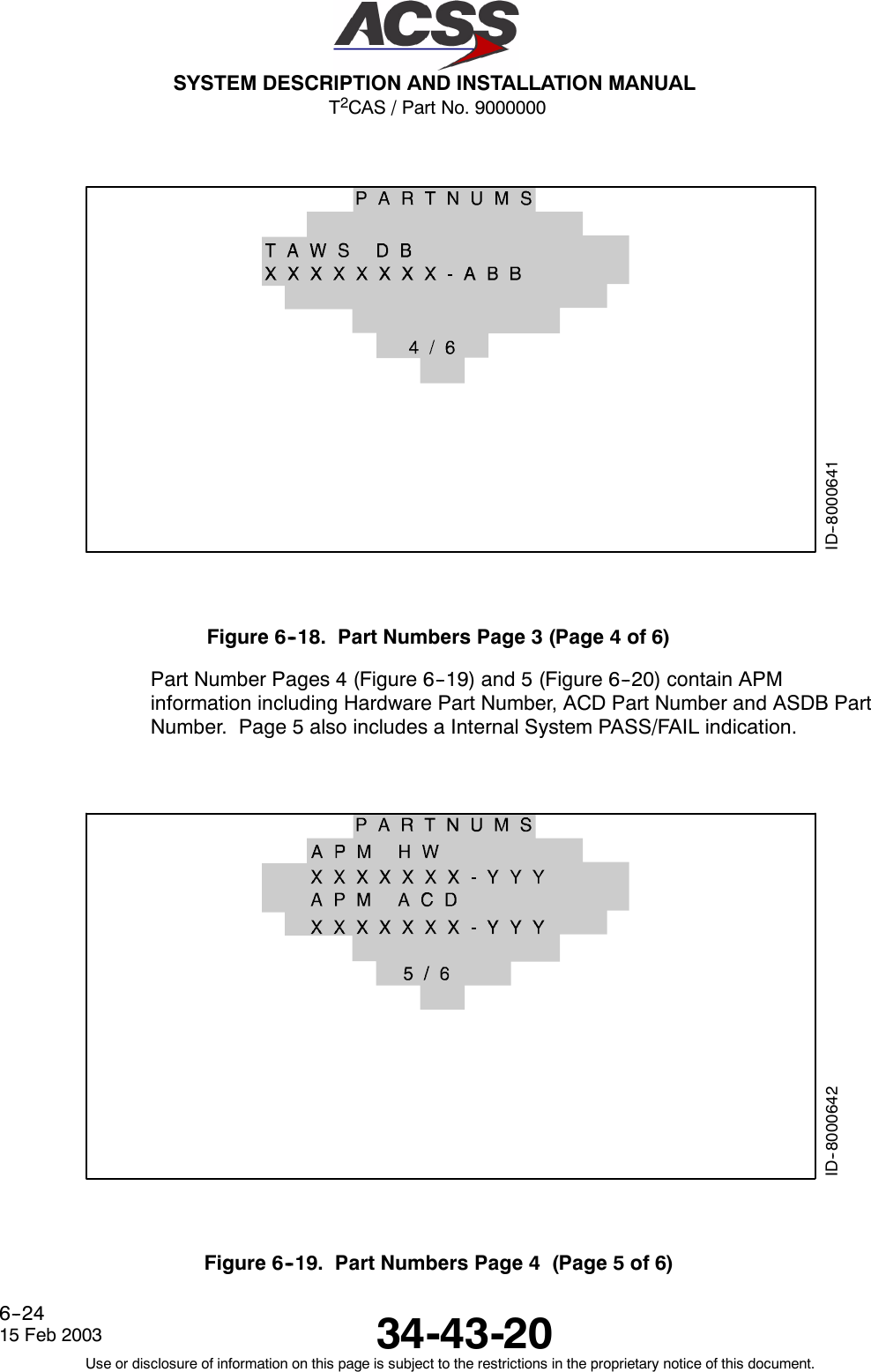
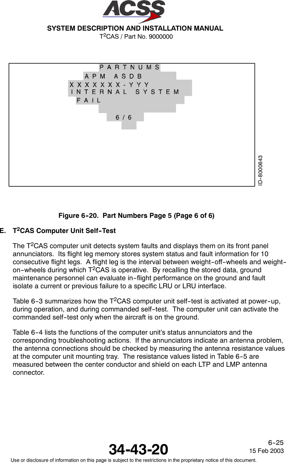
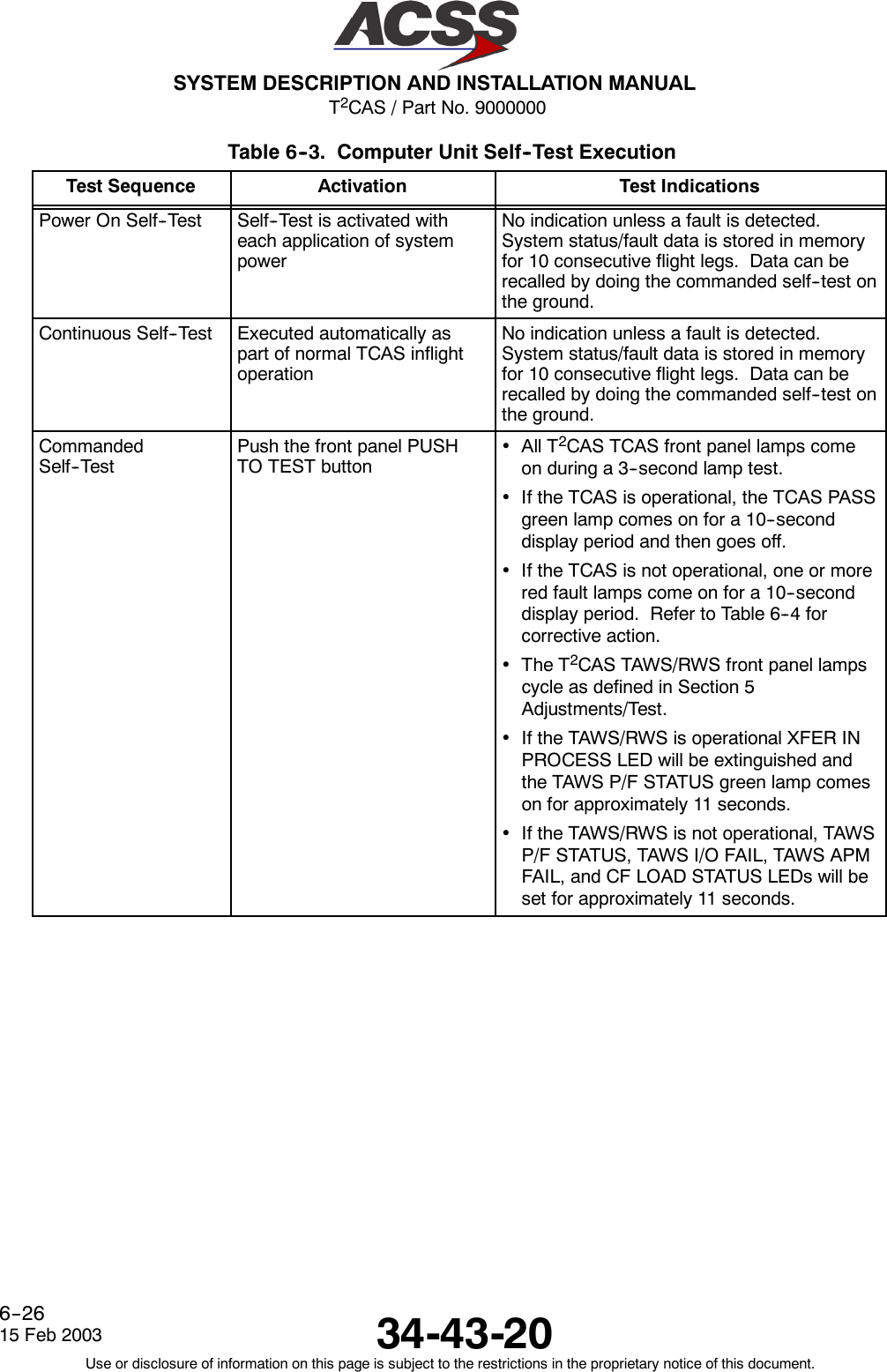
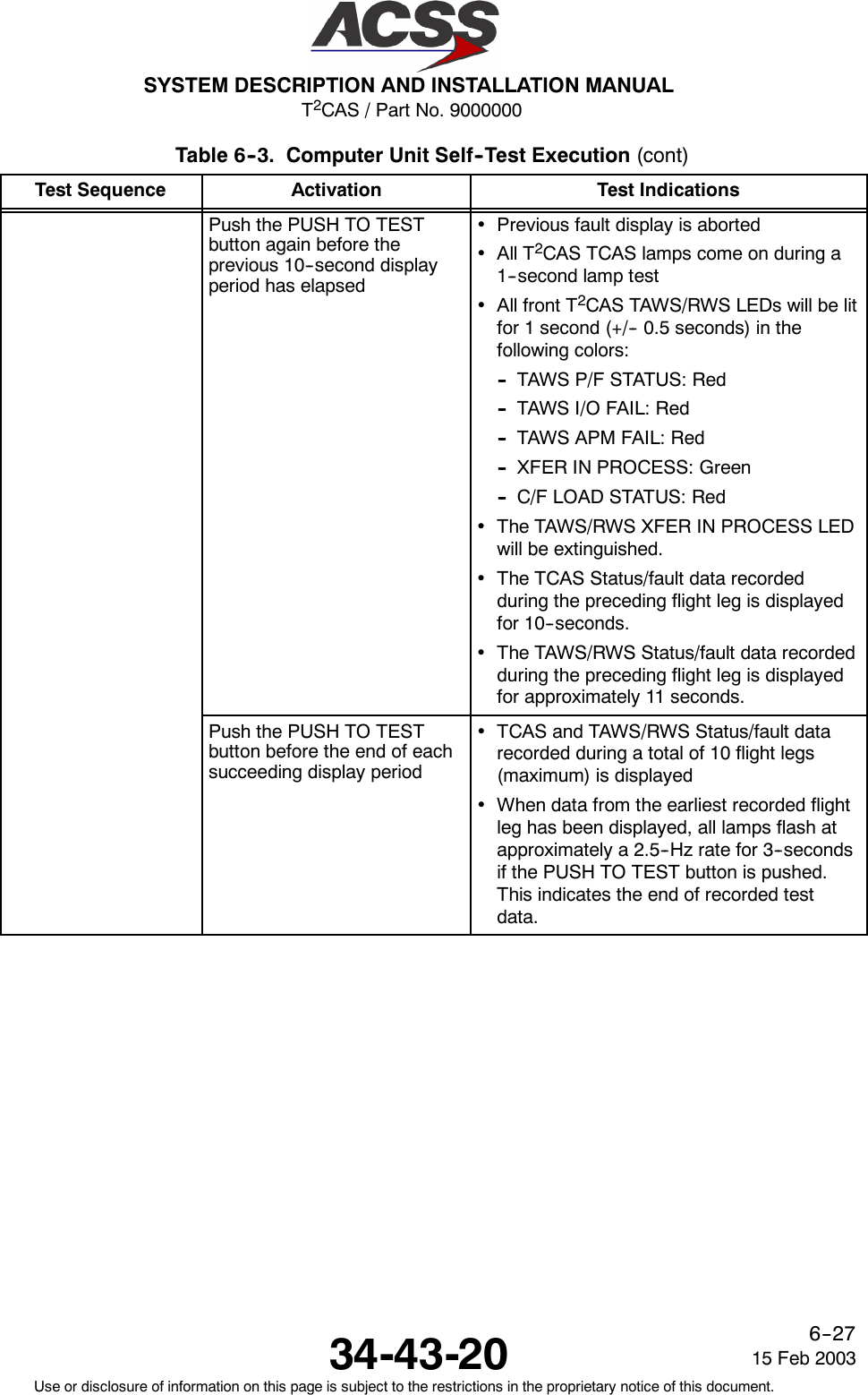
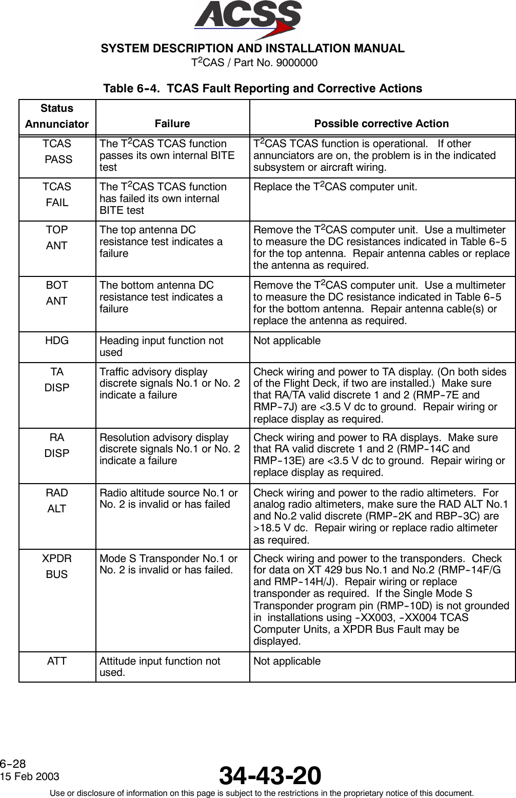
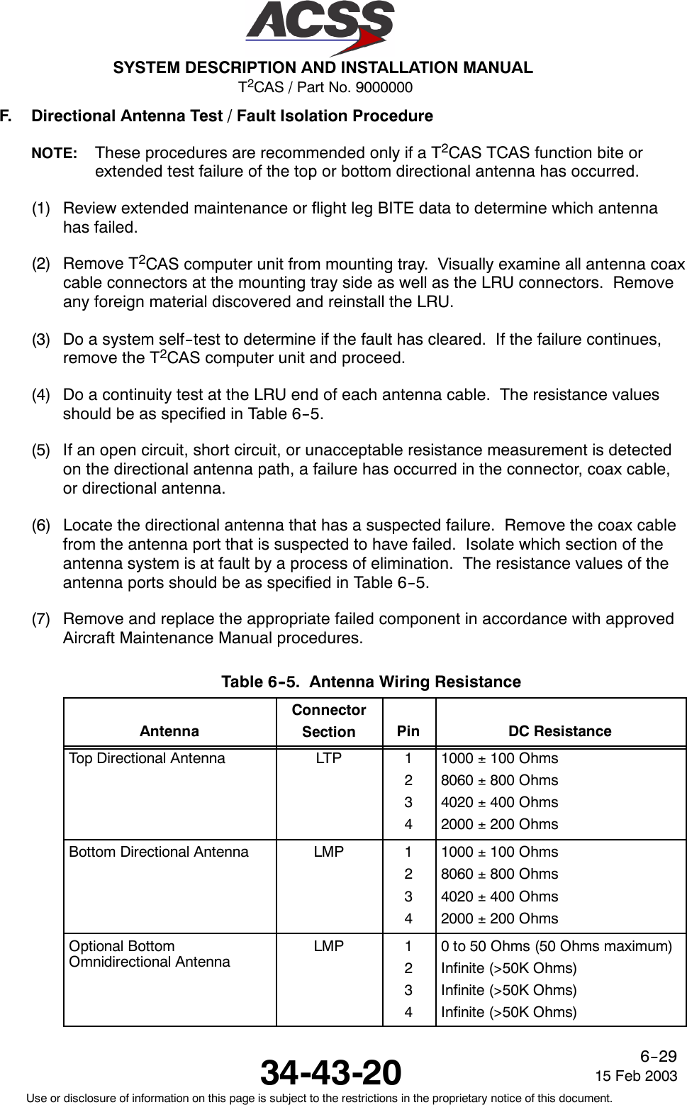
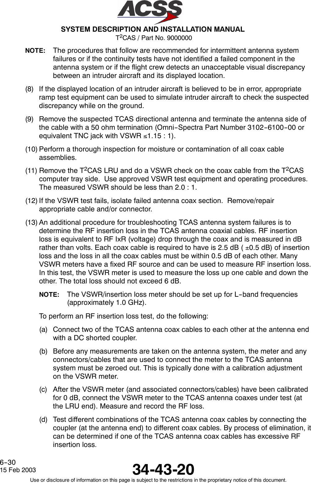
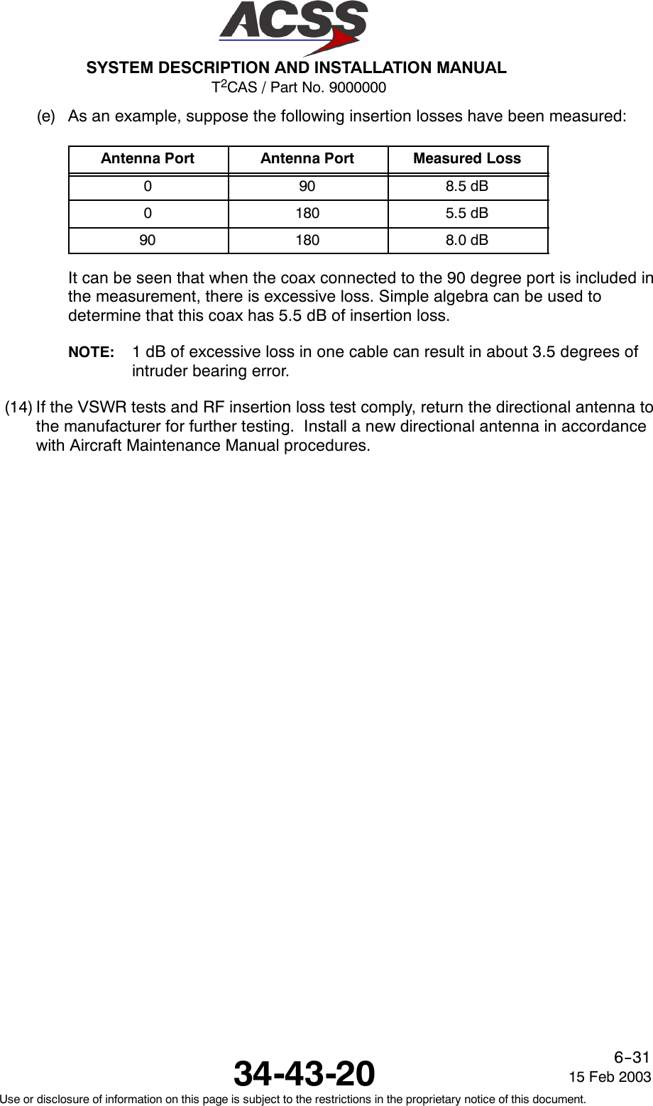

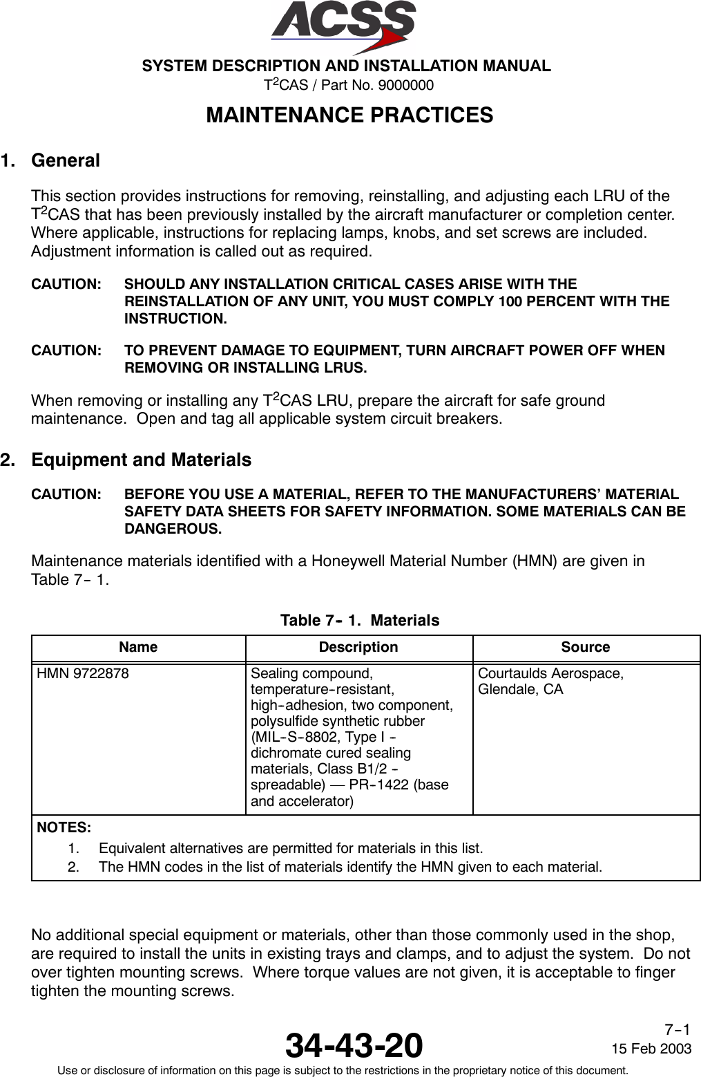
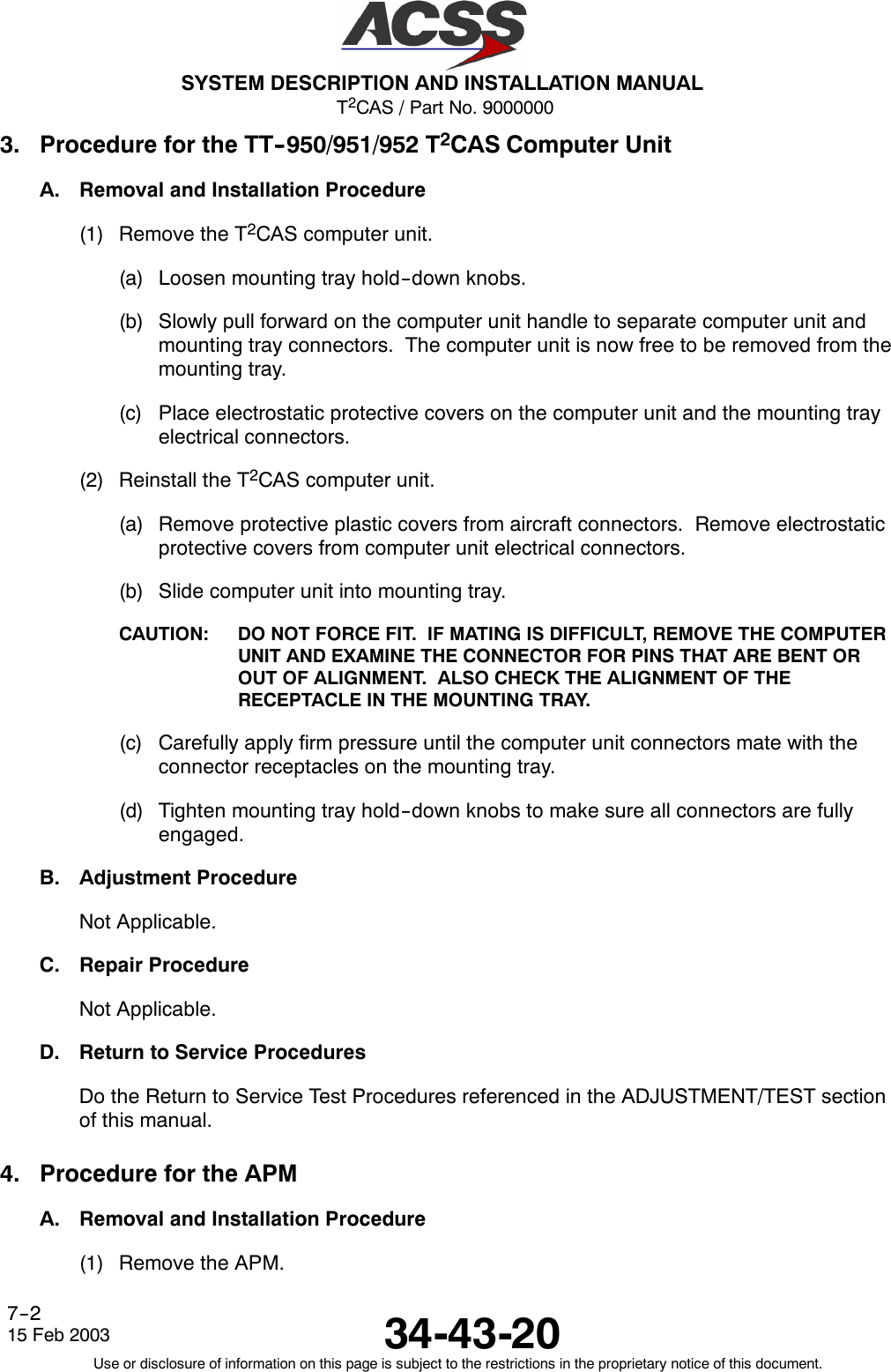
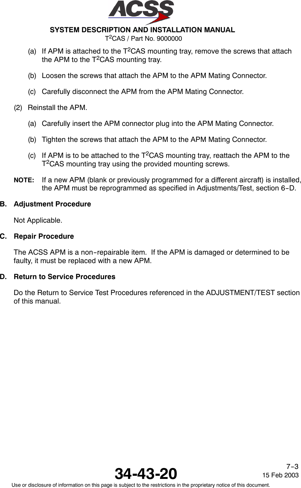
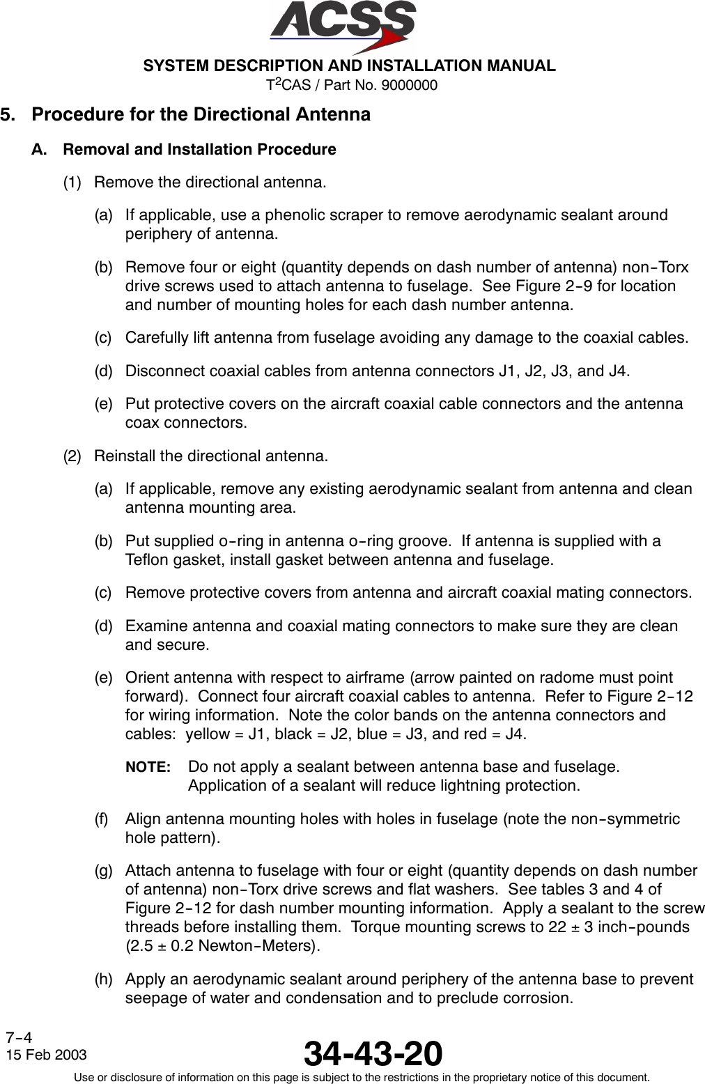
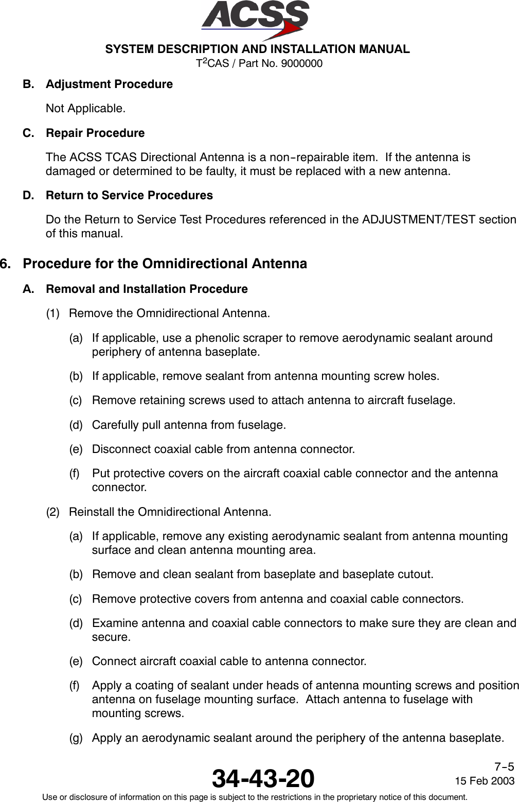

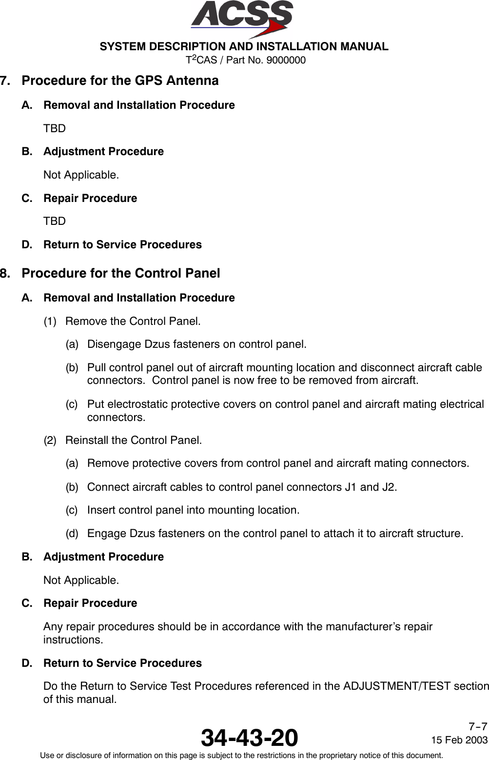
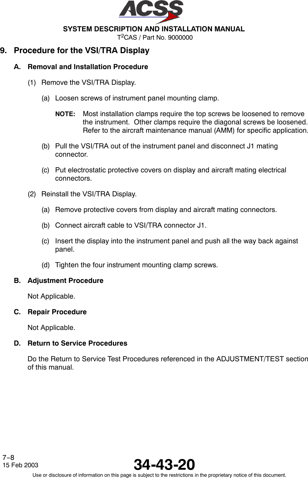
![T2CAS / Part No. 9000000SYSTEM DESCRIPTION AND INSTALLATION MANUAL34-43-20 15 Feb 2003Use or disclosure of information on this page is subject to the restrictions in the proprietary notice of this document.7--1111. Instructions for Continued Airworthiness, FAR Part 25.1529Maintenance requirements and instructions for Continued Airworthiness of the T2CAS TrafficTerrain and Collision Avoidance System components are contained in the paragraphs thatfollow:Installation of the T2CAS on an aircraft by Supplemental Type Certificate or Form 337obligates the aircraft operator to include the maintenance information provided by this manualin the operator’s AMMl and the operator’s Aircraft Scheduled Maintenance Program.A. Maintenance information for the T2CAS (system description, removal, installation, testing,etc.) is contained in this manual.B. LRU part numbers and other necessary part numbers contained in this manual should beplaced into the aircraft operator’s appropriate aircraft illustrated parts catalog (IPC).C. Wiring diagram information contained in this manual should be placed into the aircraftoperator’s appropriate aircraft Wiring Diagram Manuals.D. The T2CAS components are considered on--condition units and no additionalmaintenance is required other than a check for security and operation at normalinspection intervals.E. If a system component is inoperative, remove unit, secure cables and wiring, collarapplicable switches and circuit breakers, and placard them inoperative. Reviseequipment list and weight and balance as applicable prior to flight and make a log bookentry that unit was removed (refer to FAR Part 91.213 or the aircraft’s MinimumEquipment List [MEL]).F. The T2CAS components can be repaired only at a factory authorized repair center or anappropriately rated FAA Part 145 repair station.G. Once repaired, reinstall the LRU in the aircraft in accordance with the original Form 337approved data or instructions in this manual. Do a Return to Service test of the systemand approve it for return to service with a log book entry in accordance with therequirements specified in FAR Part 43.9.](https://usermanual.wiki/ACSS-an-L-3-Communications-and-Thales/TT-950.User-Manual-Part-2/User-Guide-302828-Page-196.png)