ADC Telecommunications AUAC85 Ultra WAVE BTS User Manual UltraWAVE BTS Installation and Commissioning Guide
ADC Telecommunications Inc. Ultra WAVE BTS UltraWAVE BTS Installation and Commissioning Guide
UserManual.wiki
>
ADC Telecommunications
>
AUAC85 User Manual
User Manual
Navigation menu
Upload a User Manual
Namespaces
Wiki Guide
HTML
PDF
Info
Views
User Manual
Discussion / Help
Navigation
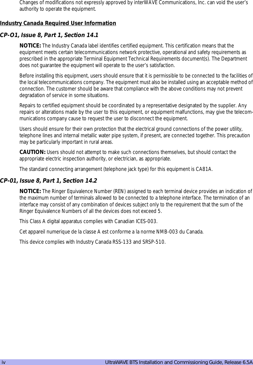

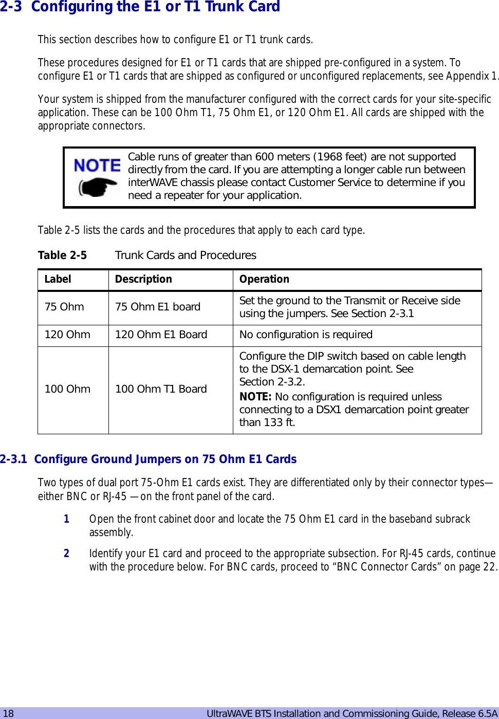
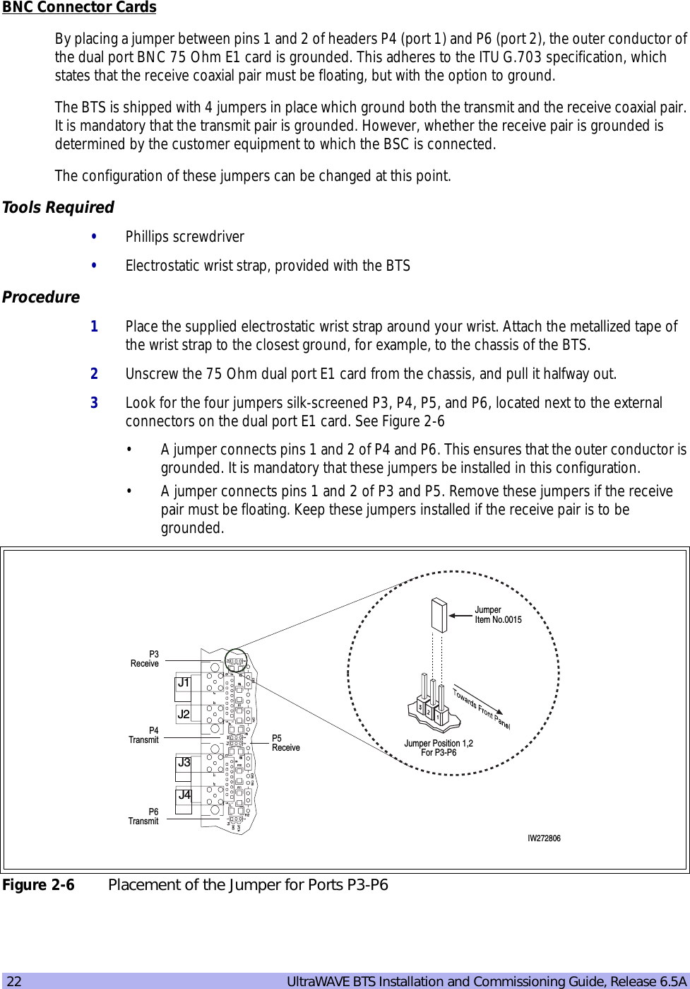
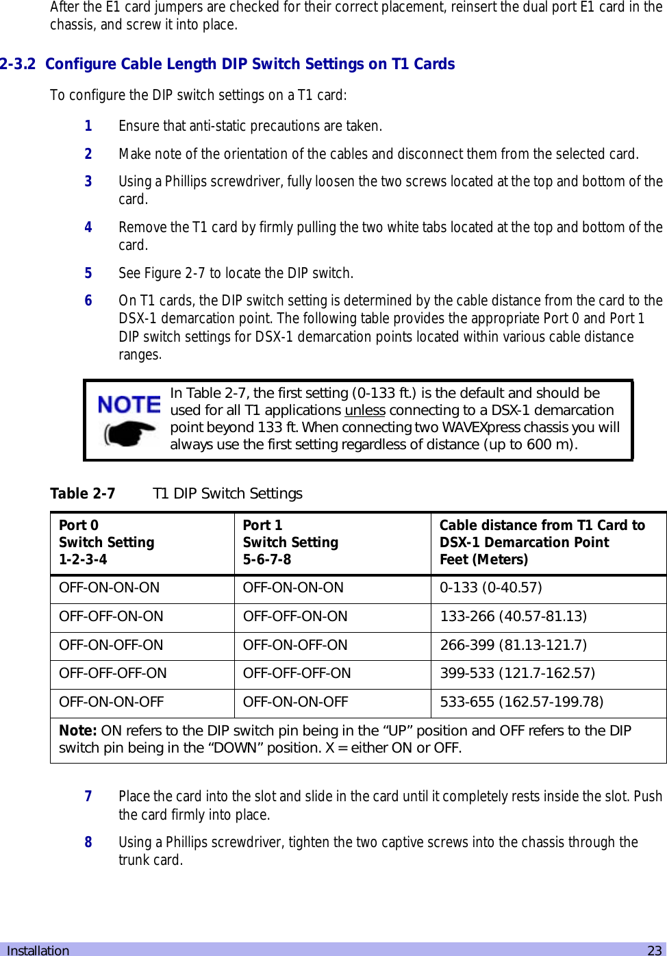
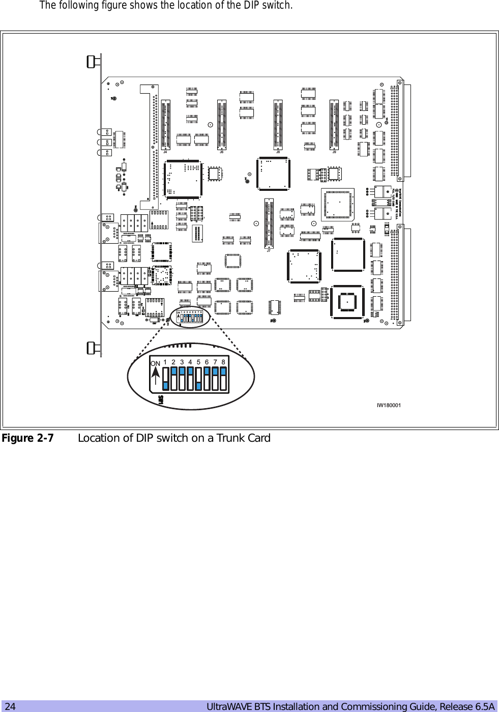
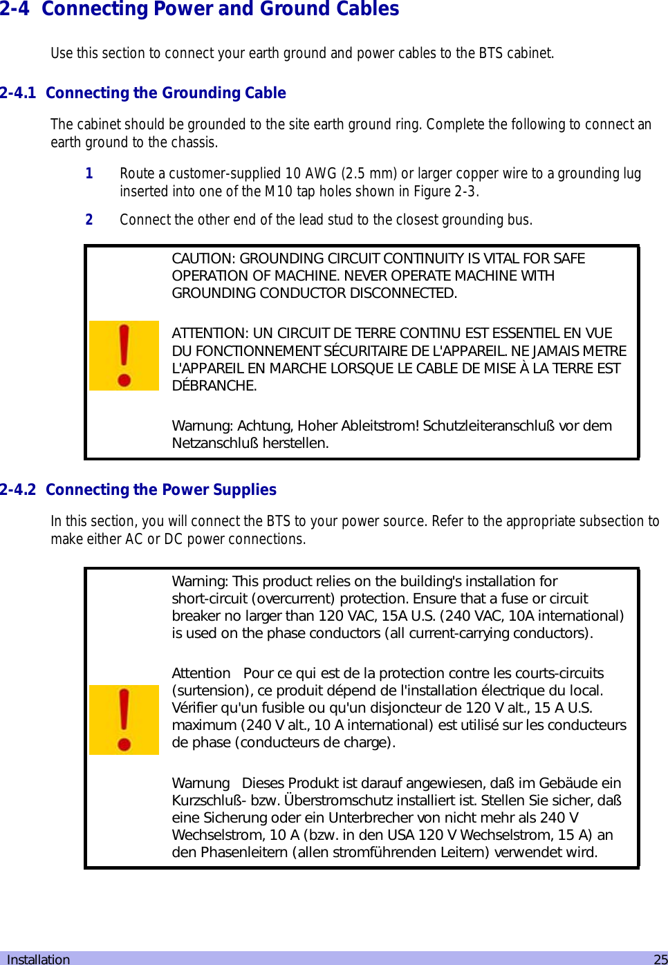
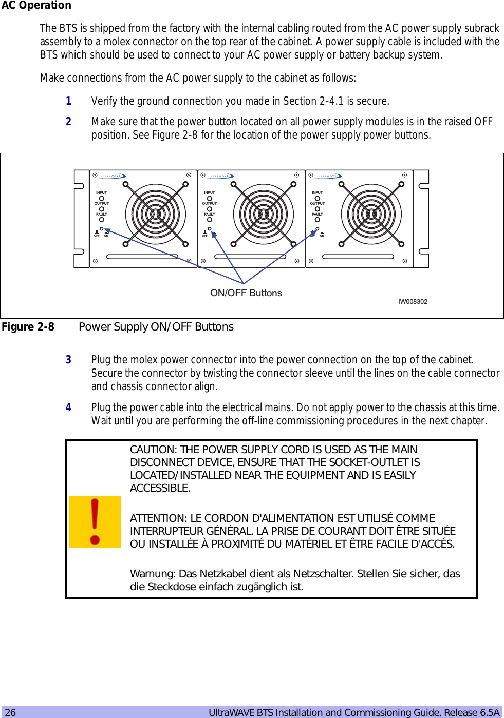
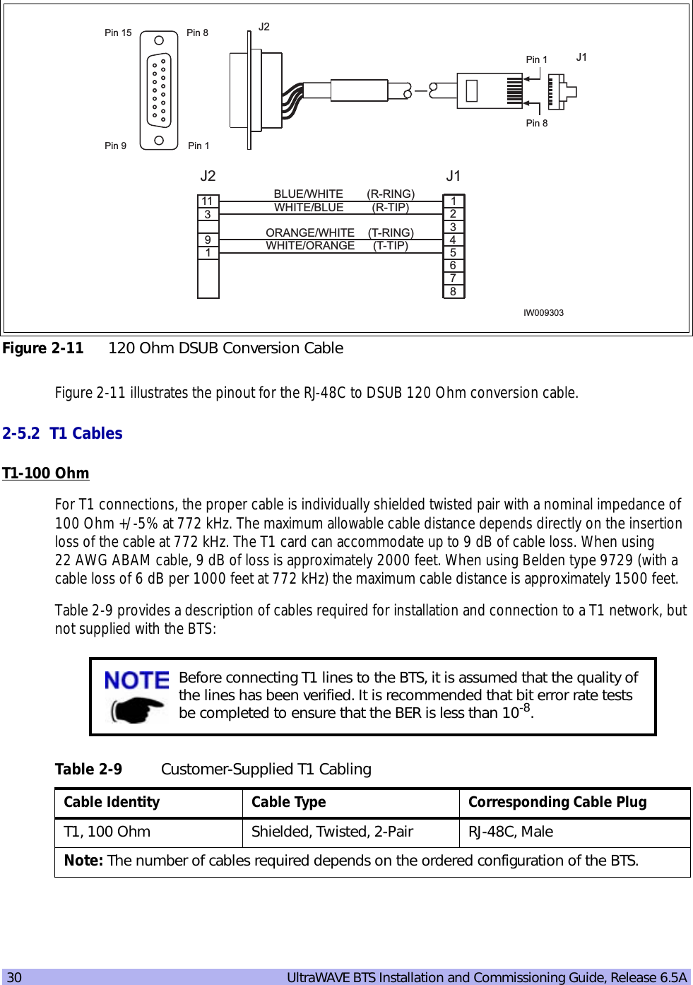
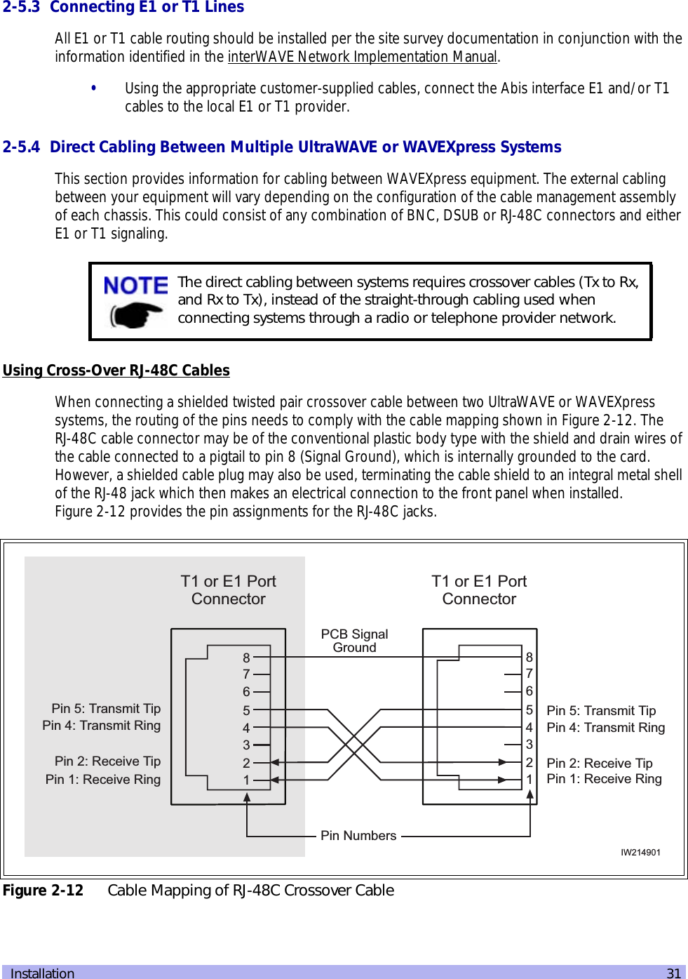
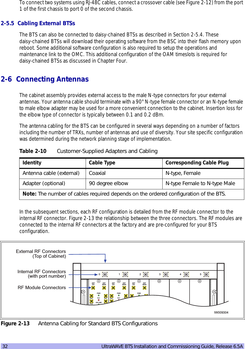
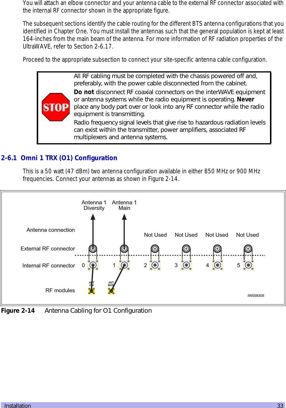
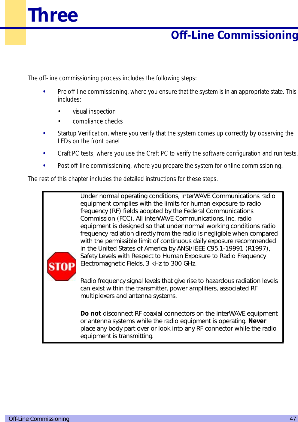
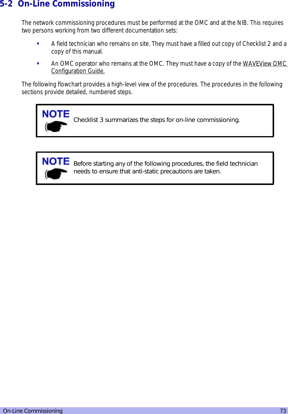
![xii UltraWAVE BTS Installation and Commissioning Guide, Release 6.5AConventions Used in this ManualThe following type and style conventions are used in this manual:Table 1 Conventions Used in This Manual Convention MeaningBody text Used for regular body textBold Indicates a menu or button choiceCommand Indicates computer generated text and promptsUser Input Indicates user input<hostname> In command syntax, indicates user-specified command line parameters<variable> In body text, indicates user-specified command line parameters[BRACKETS] Indicates a key on the keyboard or instrumentProvides relevant additional informationProvides important warning information that may affect operation of or maybe a potential threat to the systemUsed to tell the reader to STOP what they are doing and to read important instructions that are vital to prevent equipment or software damage](https://usermanual.wiki/ADC-Telecommunications/AUAC85/User-Guide-307193-Page-12.png)
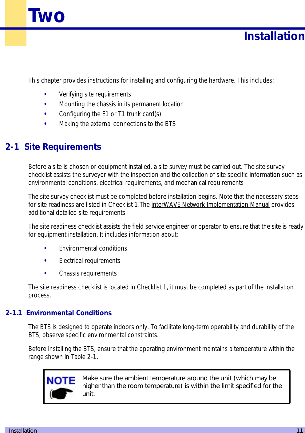
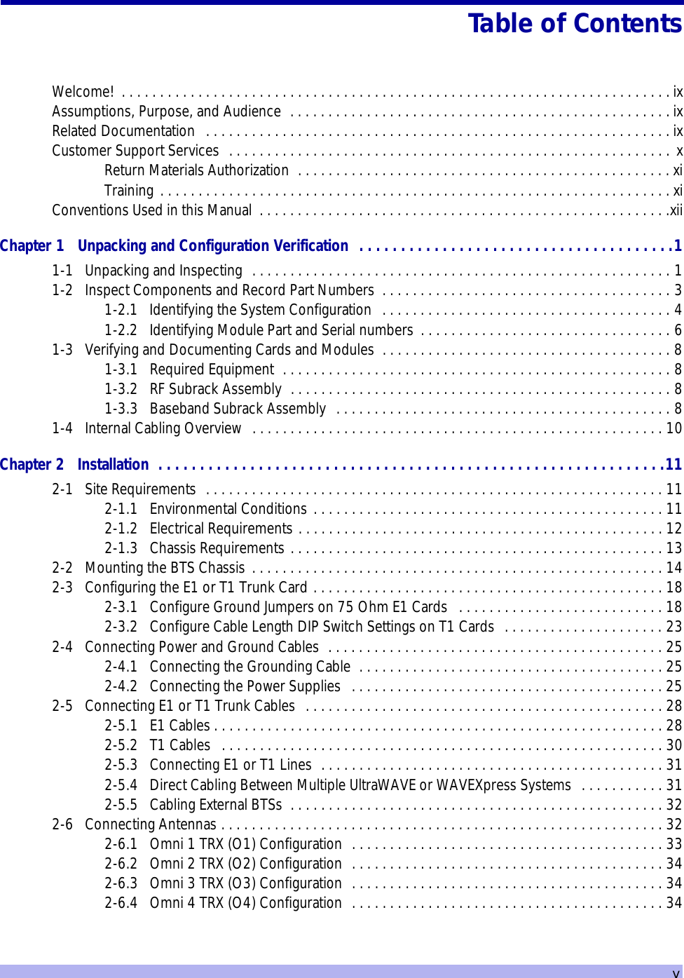
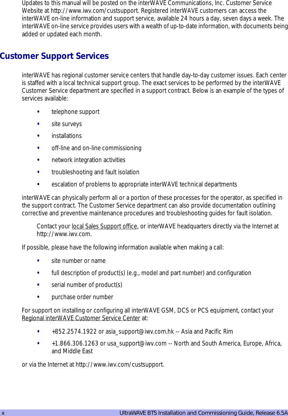
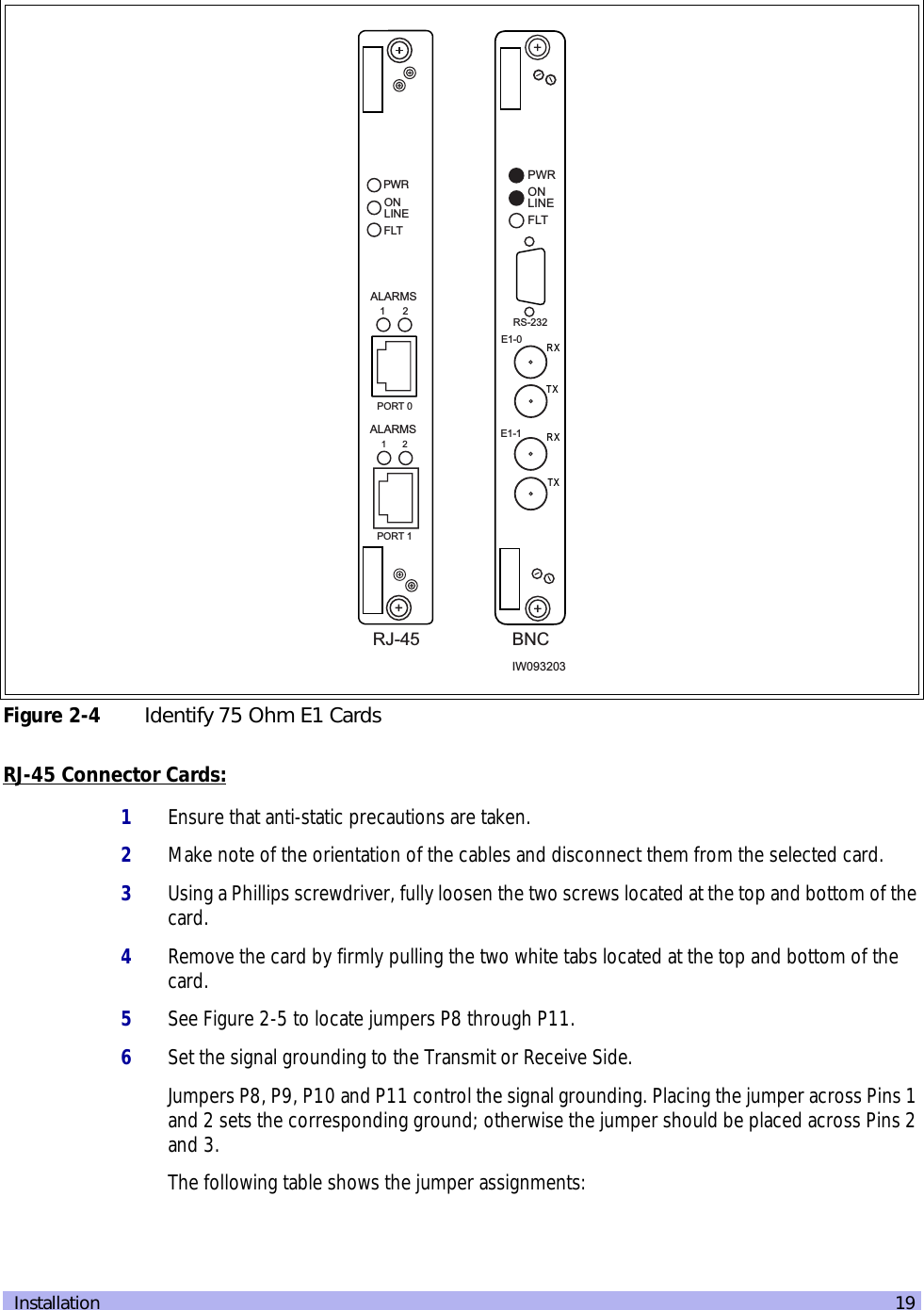
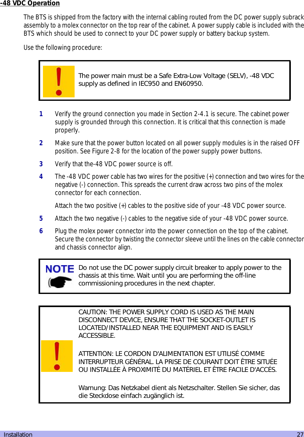
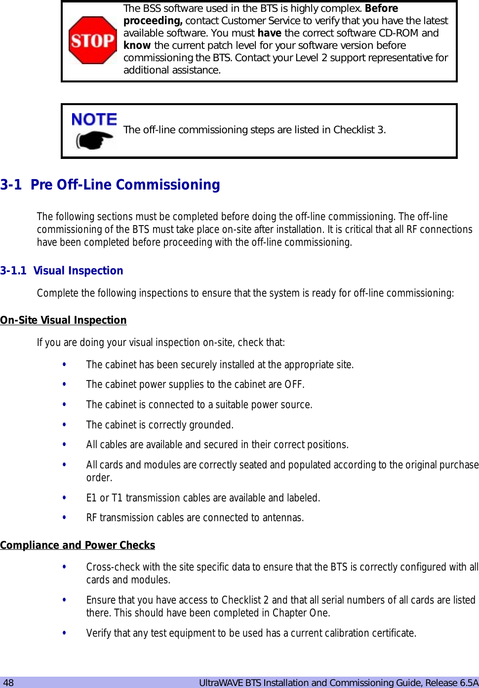
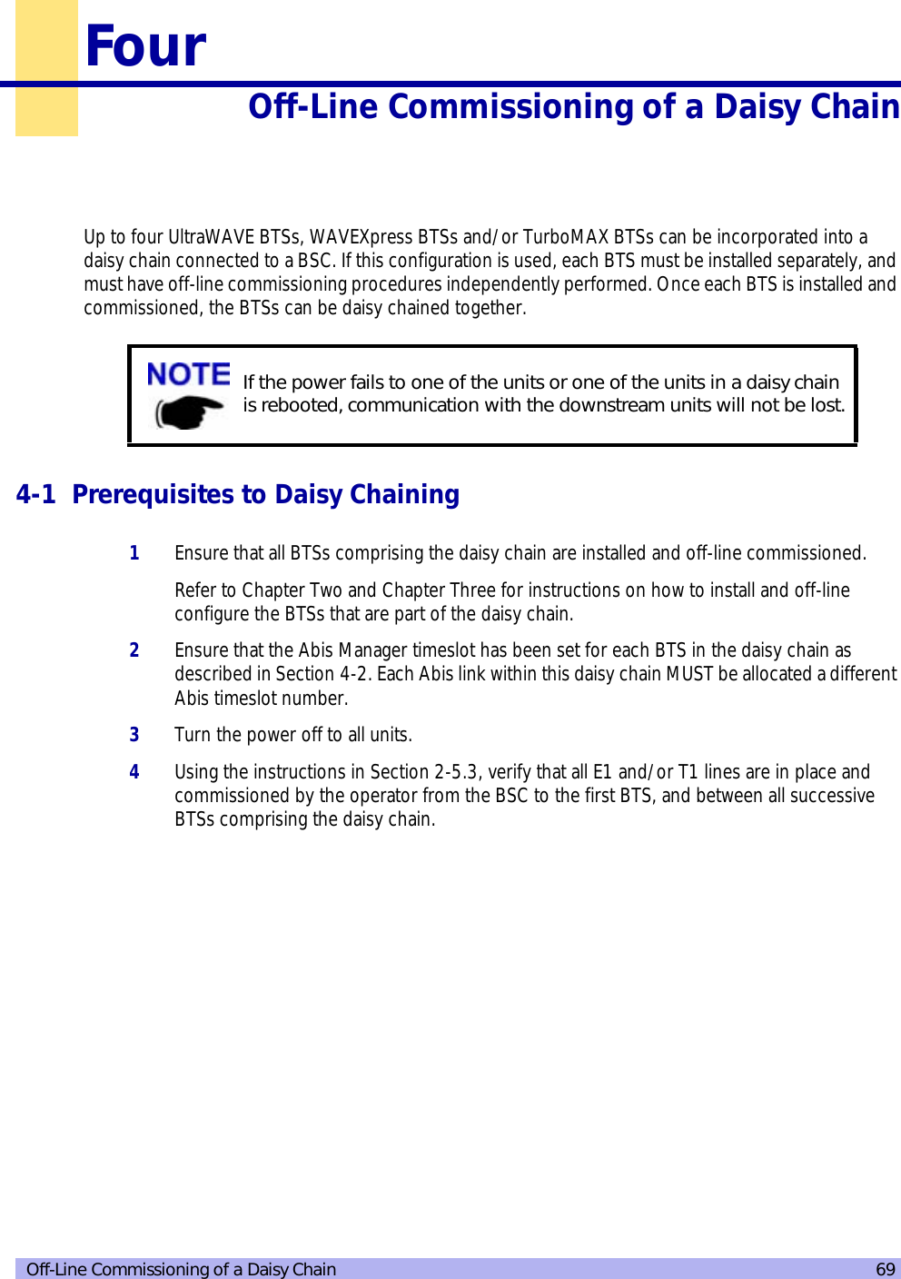
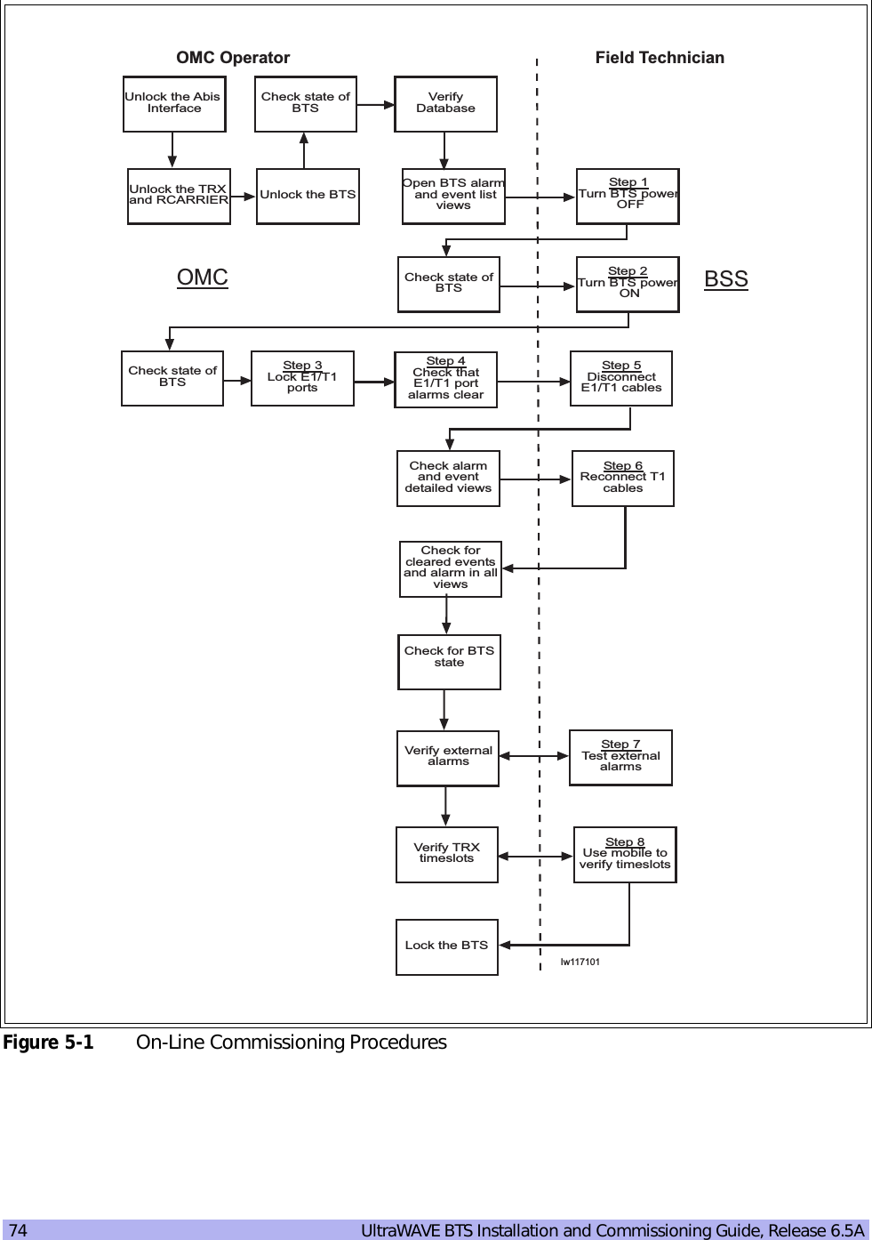
![Installation 132-1.3 Chassis RequirementsBefore installing the BTS, ensure that adequate clearing space is allowed around the unit. The BTS should be installed away from salt spray and in an area where there are minimal vibrations. Table 2-4 shows the dimensions of the BTS. For detailed cabinet dimensions, see Section 2-2.BTS power protection: -48 VDC dedicated 45 amp fuse/circuit breakerTable 2-4 BTS Cabinet DimensionsWeight (Maximum Configuration) Height Width DepthMetric 213 Kg 105.1cm 56.0 cm 64.77 cmImperial 470 lbs 41.38 inches 22.05 inches 25.5 inchesFigure 2-1 Cabinet DimensionsTable 2-3 Power Specifications (continued)Power Requirements SpecificationWHEEL_SVWHEEL_SVWHEEL_FVWHEEL_FVWHEEL_FVDOOR_FVCAB_FCAB_FV10 32 54RUBFERUBFEETRUBFEETCAB_SVDOOR_SVDOOR_SVRUBFEETRUBFERUBFEET20.925 in. [53.15 cm]M12-1.75(each corner)1.808 in[4.59 cm]19.925 in. [50.61 cm]41.375 in. [105.09 cm]IW008301M10 Tap Holes(each corner)](https://usermanual.wiki/ADC-Telecommunications/AUAC85/User-Guide-307193-Page-25.png)
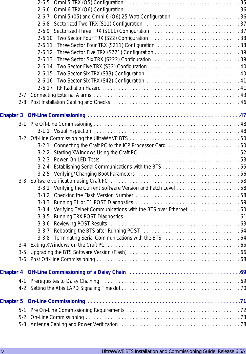
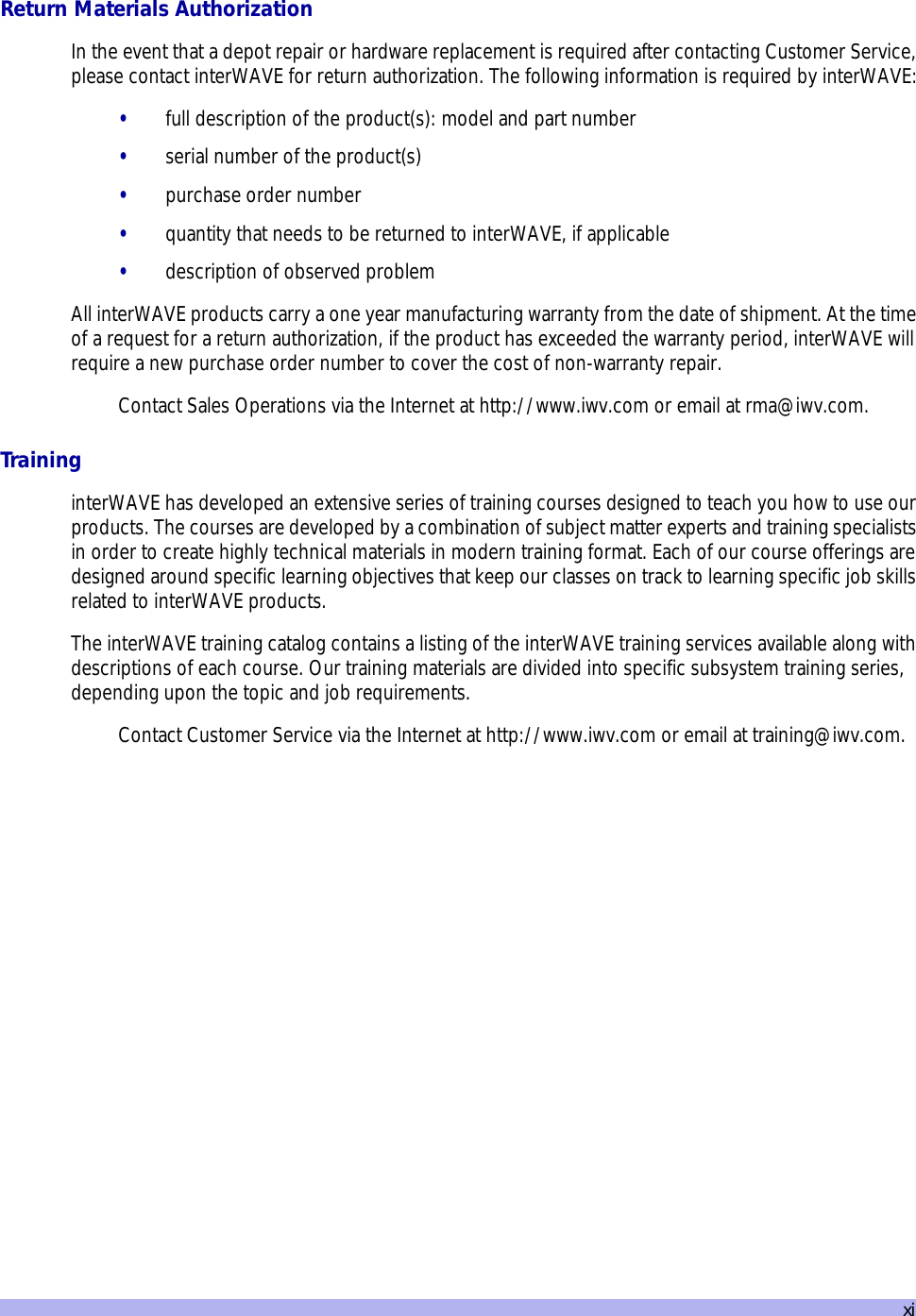
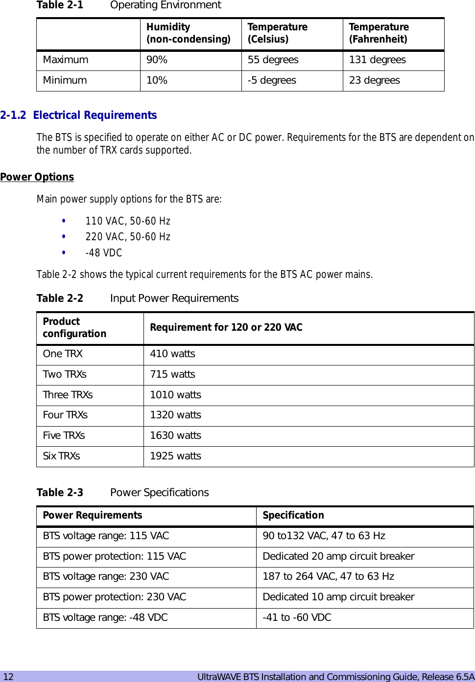
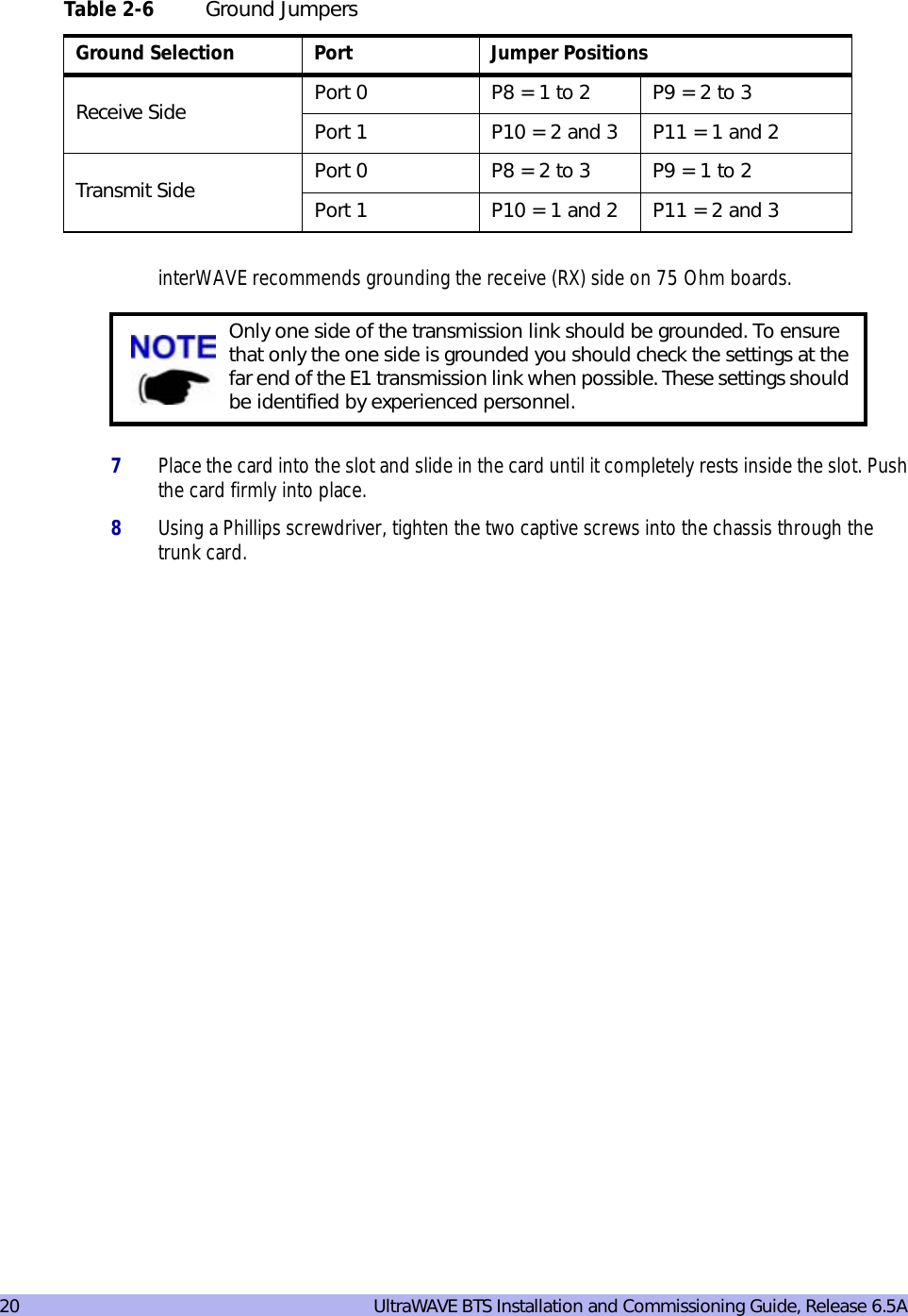
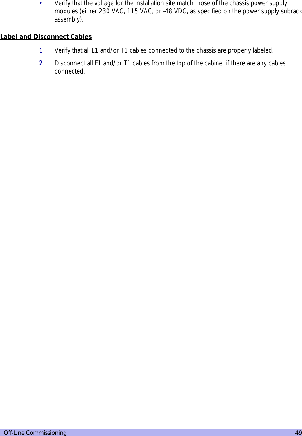
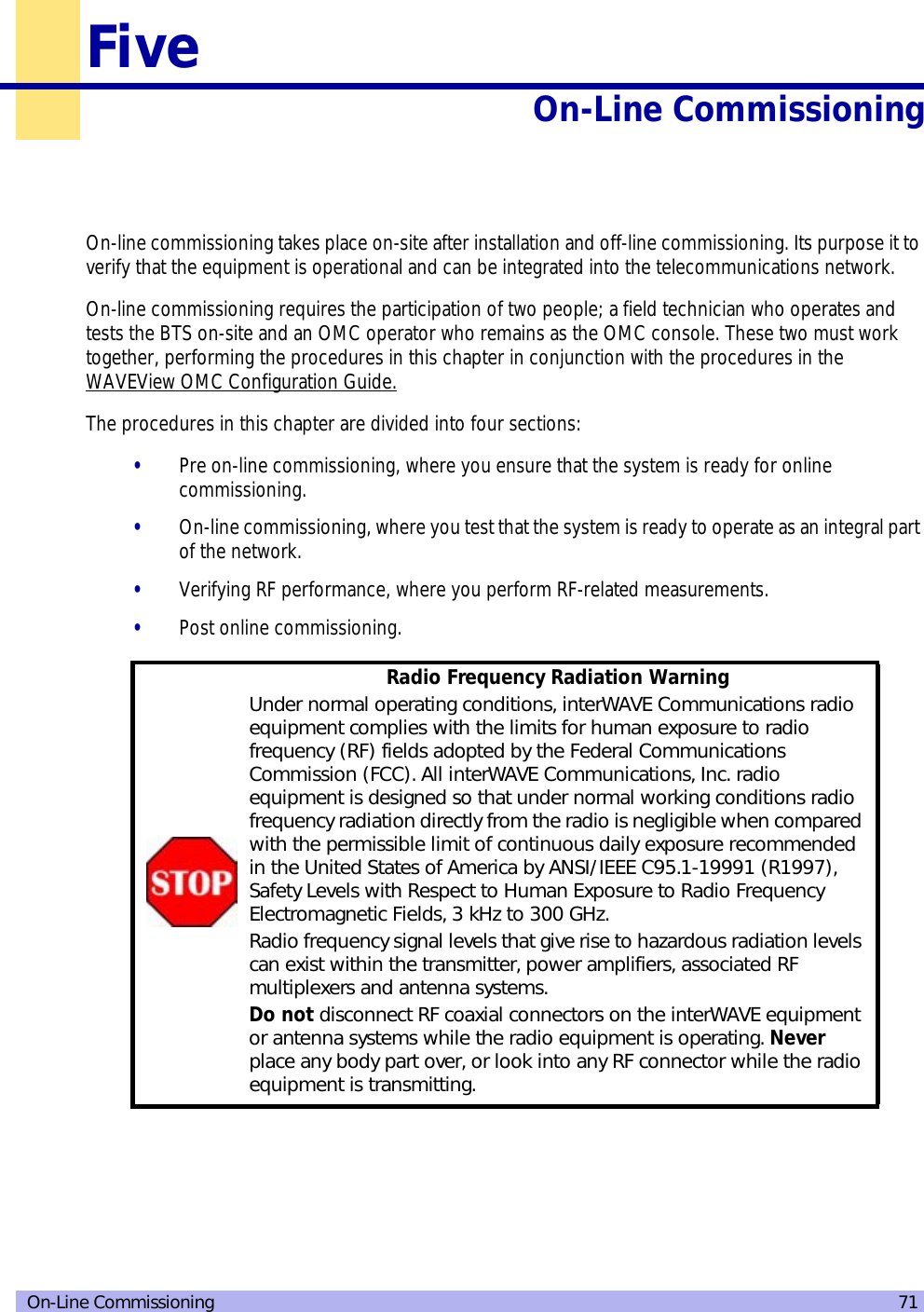
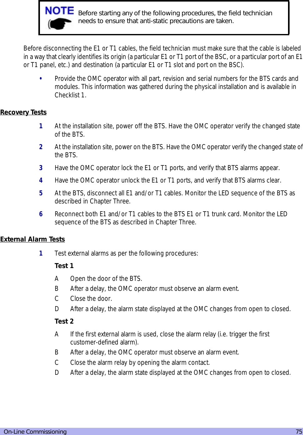
![14 UltraWAVE BTS Installation and Commissioning Guide, Release 6.5A2-2 Mounting the BTS ChassisThe BTS chassis should be mounted on a concrete pad of sufficient density to support the weight of the cabinet assembly. Alignment pins may be installed in the concrete pad at the locations provided in Figure 2-2. The alignment pins should be 0.5 inch (1.27 cm) in diameter and protrude from 4.1 in. to 4.4 in. (10.41 cm to 11.18 cm) from the concrete pad.Enough clearance should be provided from the front and back of the cabinet to fully open the doors. This requires at least 24 inches (61 cm) from the front and rear doors. The minimum clearance required on either side of the cabinet is 4.5” (11.4 cm) and the minimum clearance required below the cabinet is 1.8 inches (4.59 cm). The mounting site should also have ample clearance for the trunk and antenna cables to be attached to the connectors at the top of the cabinet.The required footprint for your cabinet installation must be at least 73.5 inches (186.7 cm) by 31.5 inches (80 cm). Be sure there is sufficient airflow around the unit.Figure 2-2 Cabinet FootprintRubber feetMounting holeM16-2 x4 places20.898 in. [53.08 cm]22.63 in. [57.48 cm]Alignment holes0.551 in. [1.40 cm]10.00 in.[25.40 cm]14.567 in.[37.00] cmIW021301](https://usermanual.wiki/ADC-Telecommunications/AUAC85/User-Guide-307193-Page-26.png)
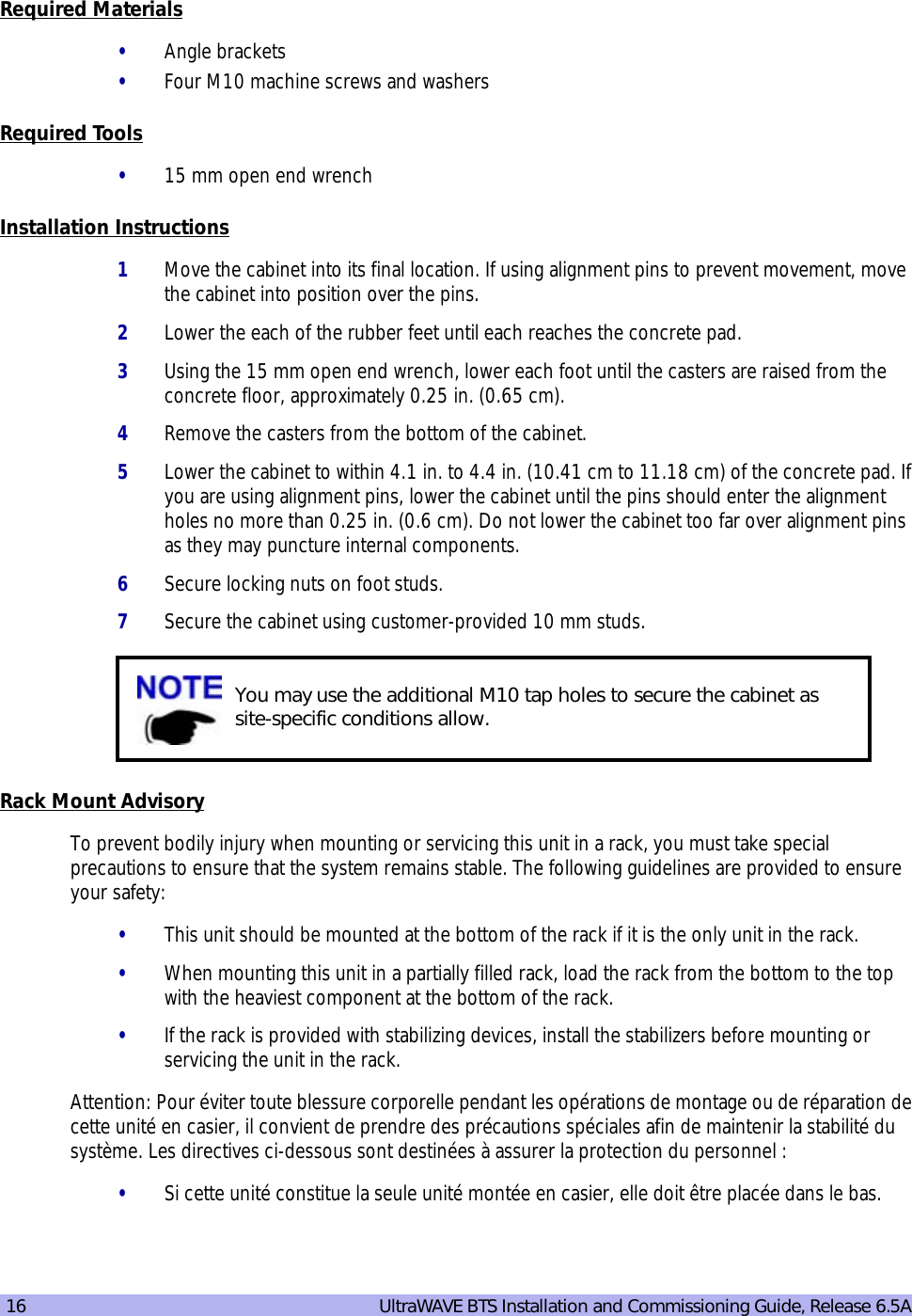
![Installation 15The cabinet is mounted on casters and may be carefully moved from the unpacking site to its final mounting location. The cabinet has four rubber which will raise the cabinet off of the castors. The dimensions for the engagement height of the rubber feet is shown in Figure 2-1. If you have alignment pins mounted in your concrete pad, use the procedure in this section.If you do not have the alignment pins, Figure 2-3 illustrates the location of eight M10 tap holes which may be used for additional mounting studs, eye hooks or angle brackets for securing the BTS cabinet in its final location.Figure 2-3 Cabinet Dimensions• Make sure the ambient temperature around the unit (which may be higher than the room temperature) is within the limit specified for the unit.• Make sure there is sufficient airflow around the unit.• Make sure electrical circuits are not overloaded - consider the nameplate rating of all the connected equipment, and make sure you have over current protection.• Make sure the equipment is properly grounded.• Make sure no objects place on top of unit.22.280 in.[56.59 cm]20.547 in.[52.19 cm]Tapped holeM10-1.5 x4 places21.280 in.[54.05 cm]40.904 in.[103.90 cm]0.750 in. [1.91] cmCabinet (side)Cabinet (top)Tapped holeM10-1.5x4 placesIW021302](https://usermanual.wiki/ADC-Telecommunications/AUAC85/User-Guide-307193-Page-27.png)

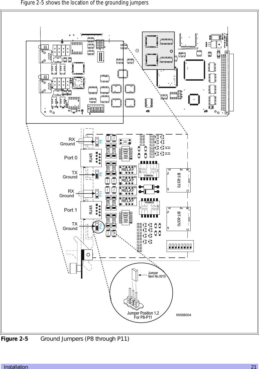
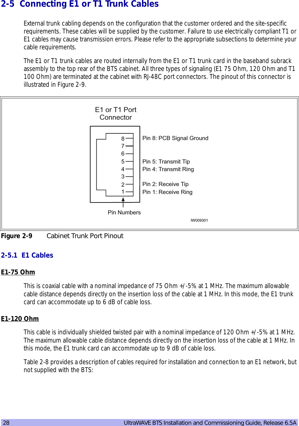

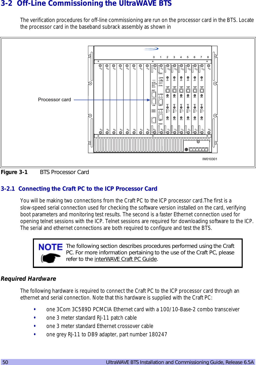
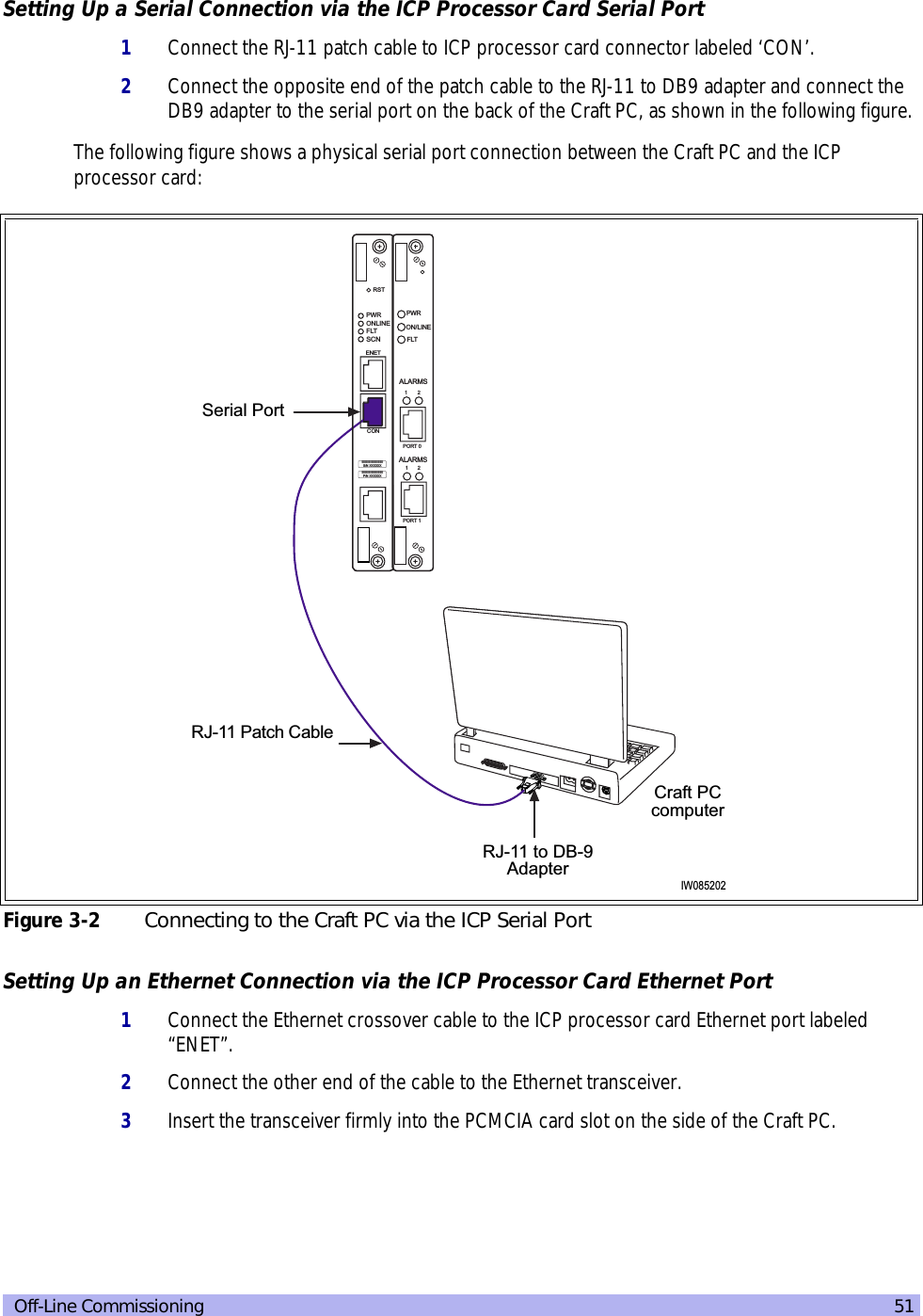
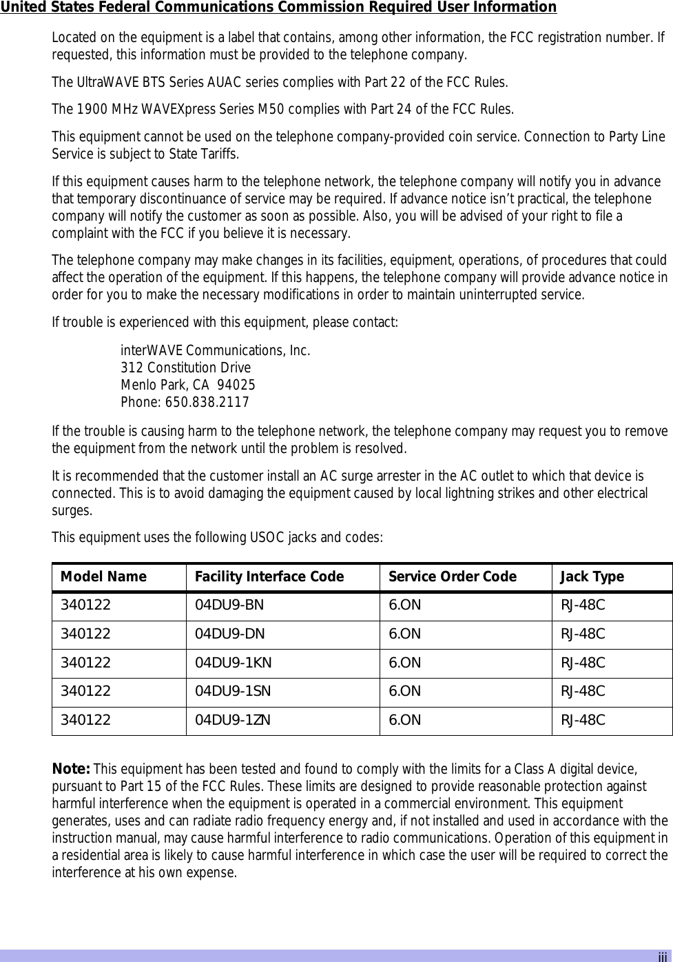
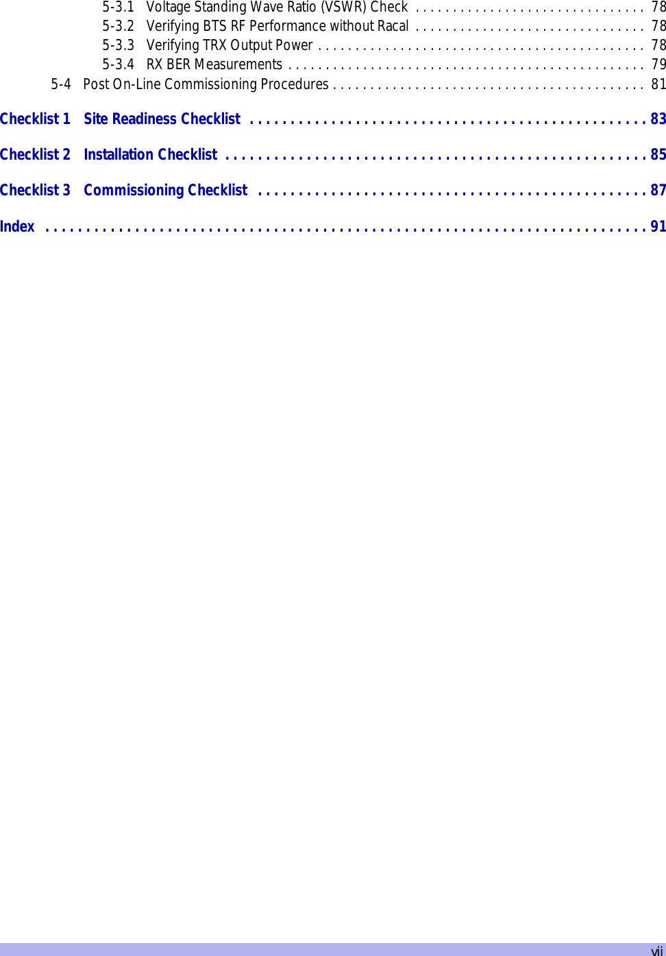
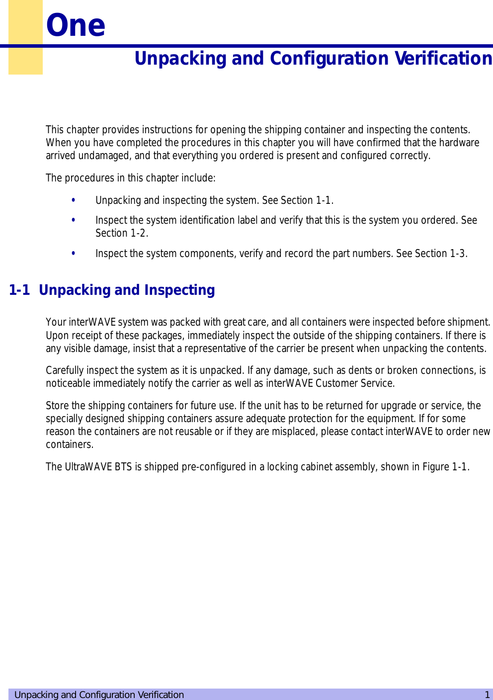
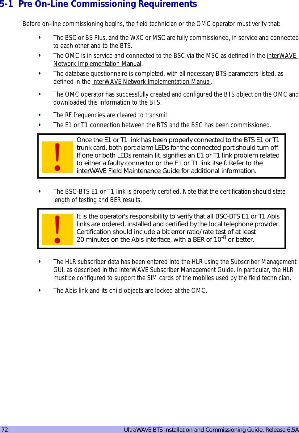
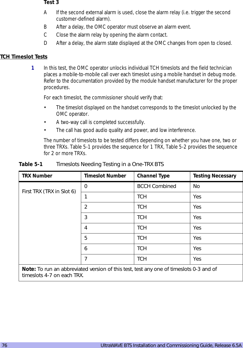
![52 UltraWAVE BTS Installation and Commissioning Guide, Release 6.5AThe following figure shows a physical ethernet port connection between the Craft PC and the ICP processor card:C3-2.2 Starting XWindows Using the Craft PCIn this chapter, you will use the Craft PC to verify the software configuration and other aspects of the BSC operation. This section describes how to start the Craft PC and the Windows environment while subsequent sections will provide connection, test and verification procedures. For information regarding the Linux based Craft PC, see the interWAVE Craft PC Guide.Starting XWindows from Windows NT/2000/XP1With your left mouse button, double click the Craft PC icon on the desktop.2If you get an error message, or if the XWindows environment does not allow you to create new XWindows, stop the CPC environment by pressing [ALT-F4] and restart the environment.The XWindows environment now starts.Figure 3-3 Connection to the Craft PC via the ICP Ethernet PortThe following sections describe procedures performed using the Craft PC. For more information pertaining to the use of the Craft PC, please refer to the interWAVE Craft PC Guide. Note that all commands in bold are those entered by the user.IW085201EthernetPortRJ-45 EthernetCrossover cableEthernetTransceiverPCMCIAcard slotCraft PCON/LINEPORT 112PORT 012ALARMSFLTPWRALARMSIIIIIIIIIIIIIIIIIIIIIIIIIP/N XXXXXXONLINEPWRFLTSCNRSTCONENETIIIIIIIIIIIIIIIIIIIIIIIIIS/N XXXXXX](https://usermanual.wiki/ADC-Telecommunications/AUAC85/User-Guide-307193-Page-64.png)
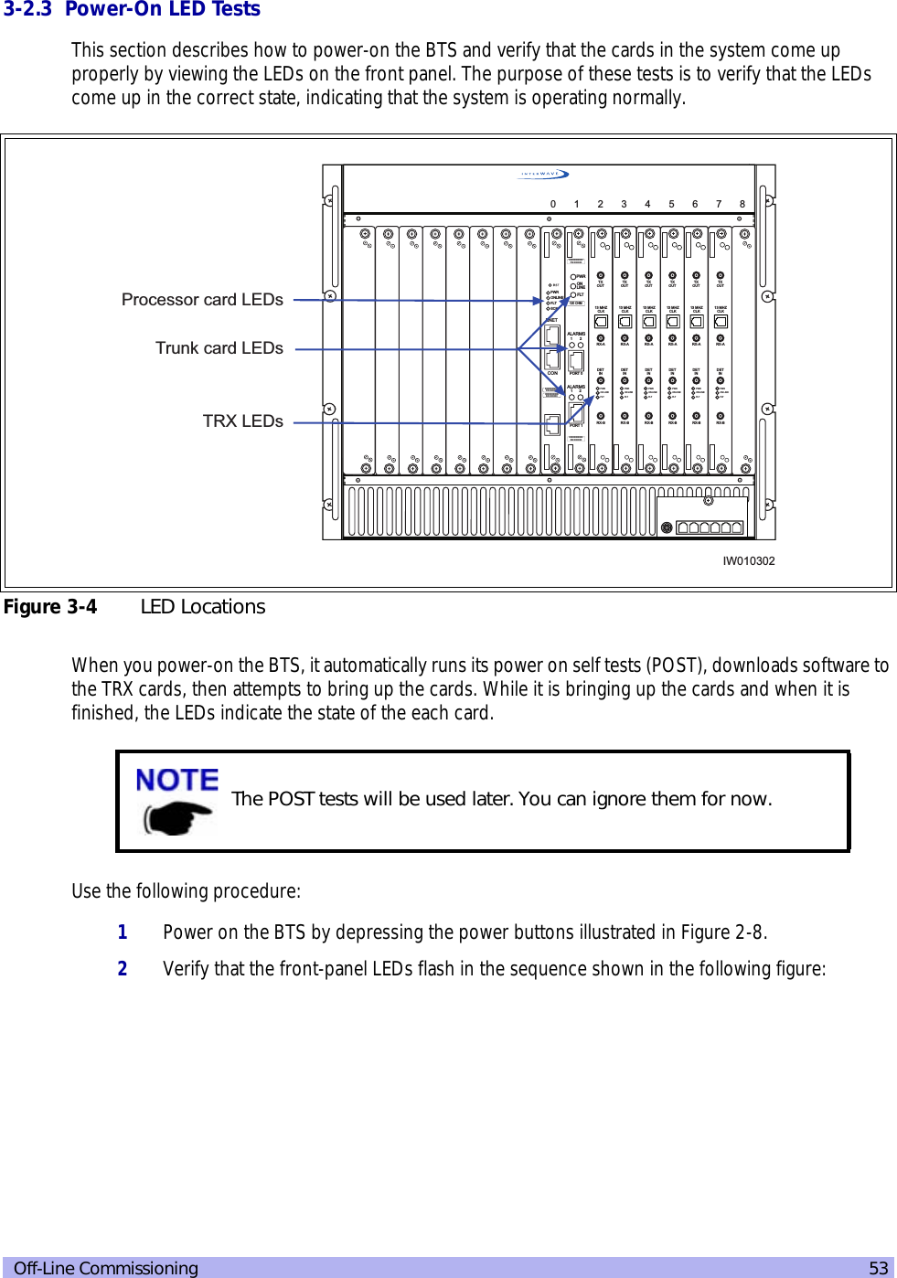
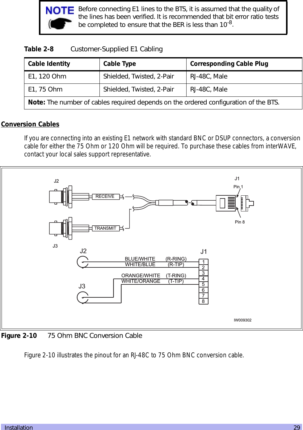
![56 UltraWAVE BTS Installation and Commissioning Guide, Release 6.5A1If not already done, connect the Craft PC to the BTS as described in Section 3-2.1, and start XWindows on the Craft PC as described in Section 3-2.2.2If an Xterm window does not launch, left click your mouse button and choose Xterm.3In an Xterm window, type:build@craftpc:~> cu -l ttyS0 [ENTER]Where l is lower case L and 0 is zero.4After the returned message Connected appears, press the [ENTER] key. The prompt now changes to the following:bts->3-2.5 Verifying/Changing Boot ParametersIn this section, you verify the boot parameters and change them if necessary. There are three reasons to change boot parameters:•If they are configured incorrectly, you must set them to the values shown here.•If your system is connected to the Ethernet, you must set the IP address to support the Craft PC IP address 172.16.80.43. To make a connection with the Craft PC, set the processor card IP address to 172.16.80.42:fffff000.•The TARGET NAME sets the IP name, and provides text for the prompt. Contact your network administrator if you are unsure what value to enter. The default is “iwbox”. After changing the boot parameters, the BTS must be rebooted before the changes take effect.1If not already done, establish serial communications with the BTS as described in Section 3-2.4. If the BTS starts rebooting endlessly, refer to the interWAVE Craft PC Guide for corrective measures. If the BTS boots normally, type:bts-> bootChange [ENTER]2A list of boot parameters appears. Use the following commands to edit the parameter values:For more information about the Craft PC, refer to the interWAVE Craft PC Guide. The following section describes procedures performed using the Craft PC. For more information about the Craft PC, please to the interWAVE Craft PC Guide.](https://usermanual.wiki/ADC-Telecommunications/AUAC85/User-Guide-307193-Page-68.png)
![Off-Line Commissioning 573For the new parameters to take effect, reboot the chassis by pressing the key combination [CTRL][x].Table 3-2 Changing Boot ParametersCommand Action[ENTER] Accepts the current parameter value and proceeds to the next parameter.. [ENTER] Erases the current parameter value and proceeds to the next parameter.- [ENTER] Returns to the previous parameter.[CTRL][d] Aborts all changes and reverts to the current values.'.' = clear field; '-' = go to previous field; ^D = quitboot device : motfcc processor number : 0 host name : craftpc file name : /home/target/vxWorks.ppc inet on ethernet (e) : 172.16.80.42:fffff000 inet on backplane (b): host inet (h) : 172.16.80.43 gateway inet (g) : user (u) : target ftp password (pw) (blank = use rsh): flags (f) : 0x0 target name (tn) : bts startup script (s) : other (o) : motfcc value = 0 = 0x0 bts-> _ Figure 3-6 Boot Parameters for ICP Processor CardYou must edit the boot parameters to contain the EXACT values shown in bold in the above display, or the equipment will not bootup properly.](https://usermanual.wiki/ADC-Telecommunications/AUAC85/User-Guide-307193-Page-69.png)
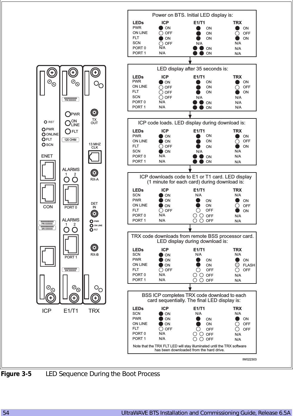
![58 UltraWAVE BTS Installation and Commissioning Guide, Release 6.5A3-3 Software verification using Craft PCIn this section, you use the Craft PC to verify the software configuration and other aspects of the BTS operation. The first sections describe how to connect and start the Craft PC; subsequent sections provide necessary test and verification procedures.3-3.1 Verifying the Current Software Version and Patch Level1If not already done, establish serial communications with the BTS as described in Section 3-2.4. 2If you have not already done so, reboot the chassis by pressing the key combination [CTRL][x]. If you do not receive a prompt after reboot, press [ENTER] to display the bts-> prompt.3After the bts-> prompt appears, verify the current software version and patch level by typing:bts-> iwversion [ENTER] BTS code version: iw06_05.ZZZ Release number: 6.5 ABIS version: 1.1 The current software version is displayed, represented above by the parameter iw06_05.ZZZ. This number should correspond to the software version detailed in the release notes included with the CD-ROM. Keep this number for your records.4Verify under Patches Installed: that the most current patch is installed, if applicable. Refer to the interWAVE Craft PC Guide for procedures to install required patches. If you are unsure if you require software patches, contact your Level 2 support representative for addi-tional assistance.3-3.2 Checking the Flash Version NumberIn order to verify that the correct software build is loaded into flash memory, go to your serial Xterm window and type:bts-> printConfigBlocks [ENTER]Figure 3-7 shows Image 0 and Image 1 from the ICP card configuration.For more information about the Craft PC, refer to the interWAVE Craft PC Guide.](https://usermanual.wiki/ADC-Telecommunications/AUAC85/User-Guide-307193-Page-70.png)
![Off-Line Commissioning 59The ICP configuration states Current Image = N where N is either 0 or 1. The flash version have lines in the format:iw06_05.ZZZwhere iw06_05.ZZZ indicates the flash version.The flash version number should be iw06_05.012 or higher for BTS TRX POST diagnostics to be able to run. If it is not, the flash version number will have to be changed and the BTS rebooted. To do this, refer to Section 3-5.3-3.3 Running E1 or T1 POST Diagnostics1Disconnect all E1 and/or T1 lines from the BTS. This ensures that no Abis connection exists. If an Abis connection does exist, the TRX POST might not run properly.2Wait until the bts-> prompt appears, and type: bts-> reboot [ENTER]**** Current Image = 1 ************ Image 0 ********* Image IW version : iw06_05.011 Image creation date: 04/15/02 13:44 Image crc : 1ff03d8d******** Image 1 ********* Image IW version : iw06_05.012 Image creation date: 04/09/02 12:07 Image crc : e3b05e8c******** Image 2 ********* Image IW version : iw06_00.028 Image creation date: 04/09/02 12:07 Image crc : e3b05e8cFigure 3-7 Determining the Flash Version on ICP Processor CardFlash Image 2 is reserved for interWAVE Customer Service use ONLY.](https://usermanual.wiki/ADC-Telecommunications/AUAC85/User-Guide-307193-Page-71.png)
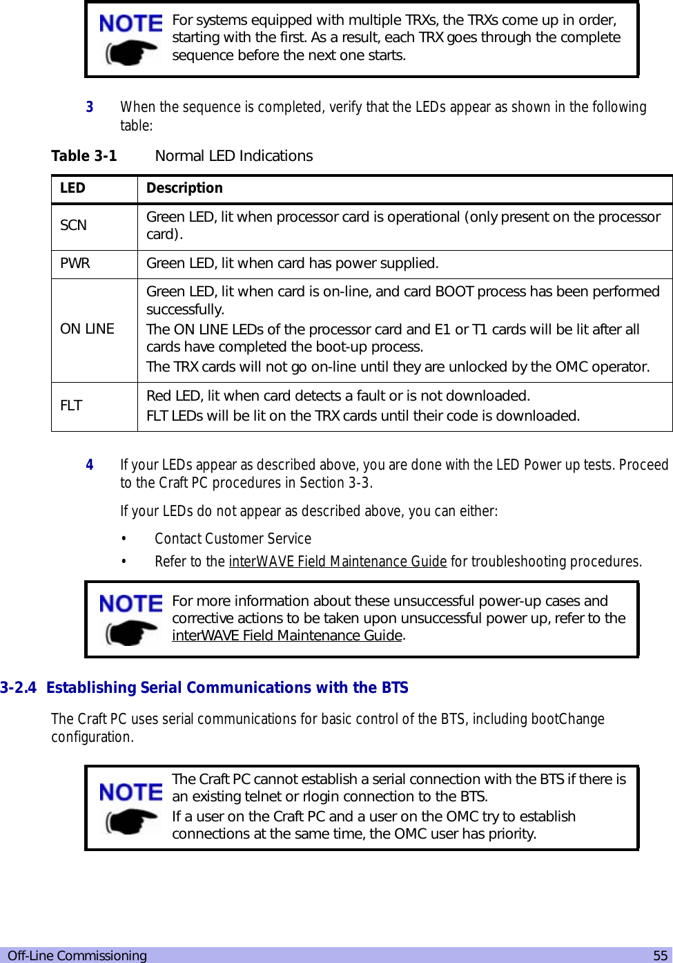
![60 UltraWAVE BTS Installation and Commissioning Guide, Release 6.5AThis action reboots the BTS. The VxWorks kernel is started, several E1 or T1 trunk card tests run sequentially, and the results of each test are listed as PASSED/FAILED. Only if all seven tests passed successfully will the E1 or T1 POST diagnostics be considered successful. The E1 or T1 POST results will be displayed after the boot process has been completed:3The above display shows the E1 or T1 POST results that would appear if the E1 or T1 POST diagnostics ran successfully on the E1 or T1 trunk card in slot 1. The format for each diag-nostic line is:[line number][action][E1 or T1 number][test number][test description][test result]In the case of an error, a FAILED message would appear following the test that failed. In addition, the following message would be displayed in Line 8:E1 CARD in SLOT 1: COMPLETED POST/OFFLINE Test: FAILED3-3.4 Verifying Telnet Communications with the BTS over EthernetThe Craft PC uses telnet communications across the Ethernet connection for code downloads and to use the proprietary Network Management Interface (NMI) for BTS testing. Before performing any of the following procedures, ensure that you can establish and terminate a telnet communications session as described in the following procedures.The coding for the E1 or T1 trunk card, its modules and scripts generically refer to the E1 or T1 trunk card objects as “E1”, whether the corresponding ports are configured as E1 or T1.1 (e1diag) E1 CARD in SLOT 1: STARTING POST/OFFLINE Test2 (e1diag) testsPtr 0xffb33ab4 testsPtr[0] 0x53 (e1diag) testsPtr 0xffb33ab4 testsPtr[0] 0x5 result 0x0 i 14 (e1diag) E1(1) TID01: Initialize Peripheral Registers: PASSED5 (e1diag) testsPtr 0xffb33ab4 testsPtr[0] 0x5 result 0x0 i 26 (e1diag) E1(1) TID02: Peripheral Register Test: PASSED7 (e1diag) testsPtr 0xffb33ab4 testsPtr[0] 0x5 result 0x0 i 38 (e1diag) E1(1) TID03: Framer Register Test: PASSED9 (e1diag) testsPtr 0xffb33ab4 testsPtr[0] 0x5 result 0x0 i 410 (e1diag) E1(1) TID04: VME to CPU FIFO Flag Test: PASSED11 (e1diag) testsPtr 0xffb33ab4 testsPtr[0] 0x5 result 0x0 i 512 (e1diag) E1(1) TID05: Initialize Time/Space sw Chip: PASSED13 (e1diag) testsPtr 0xffb33ab4 testsPtr[0] 0x5 i 614 (e1diag) E1 CARD in SLOT 1: COMPLETED POST/OFFLINE Test : PASSEDFigure 3-8 E1 or T1 POST ResultsIf an E1 or T1 trunk card fails the POST diagnostics, remove the failed card and return it to interWAVE along with its test results file. The defective card needs to be replaced with a new one, and POST diagnostics should be run again on the new card.](https://usermanual.wiki/ADC-Telecommunications/AUAC85/User-Guide-307193-Page-72.png)
![Off-Line Commissioning 61Establishing a Telnet Communications Session1In an Xterm window, terminate the serial connection by pressing the [~] key and then the [.] key:bts-> ~.The prompt now changes back to build@craftpc:~>.2Verify that you can establish a telnet communications session by typing:build@craftpc:~> telnet iwbox [ENTER]3The Craft PC prompt now changes to bts->. This prompt verifies that the telnet session can be established. If this is not the case, verify the Ethernet wiring and retry. Terminating a Telnet Communications SessionAfter verifying that a telnet communications session can be established, terminate the telnet session as follows.4Terminate the telnet communications session by typing:bts-> logout [ENTER]The return message should read “Connection closed by foreign host” and the prompt changes back to build@craftpc->.3-3.5 Running TRX POST DiagnosticsThis section explains how to use the Craft PC to run the TRX POST diagnostics on the BTS.For more information about the Craft PC, please refer to the interWAVE Craft PC Guide.If the Craft PC hangs when attempting to establish a telnet session, press the key combination [CTRL][c] to abort the failed connection. Check the boot parameters and repeat the connection procedures. Also verify that the Craft PC host table contains the hostname of your equipment in reference to the default IP address.Once a telnet session has been established between the Craft PC and the processor card, it must be terminated before the Craft PC is powered off. FAILURE TO DO THIS WILL RESULT IN A HUNG CONNECTION ON THE BSS SYSTEM.](https://usermanual.wiki/ADC-Telecommunications/AUAC85/User-Guide-307193-Page-73.png)
![62 UltraWAVE BTS Installation and Commissioning Guide, Release 6.5A1Verify that you can establish and terminate a telnet communications session as described in Section 3-3.4.2Establish a serial connection by typing:build@craftpc:~> cu -l ttyS0 [ENTER] Connected. bts->3After the BTS has booted up and the E1 or T1 POST has run during the boot process, the TRX POST diagnostics can be initiated. Type:bts-> runtrxpost [ENTER]4A set of TRX POST diagnostic tests run sequentially over the Ethernet connection and the results of each test will be listed as PASSED/FAILED. Only if all tests passed successfully will the TRX POST diagnostics be considered successful. The TRX POST results will be displayed after the boot process has been completed.The format for each diagnostic line is:[line number][action][TRX number][test number][test description][test result]For example:14 (Diag) TRX(4) TF22: Test Basic op of VME/RTP FIFOs: PASSED where:The following example shows the TRX POST results for a one-TRX BTS. The following display shows that the TRX POST diagnostics ran successfully on the TRX card in slot 2. Figure 3-9 shows the results of the TRX POST for the GPRS enabled TRX card.The TRX ON LINE LED flashes continuously when TRX POST diagnostics are being run and does not stop flashing until the BTS is rebooted. The flashing LED can be used as a reminder to reboot the system after successfully completing the TRX POST and other diagnostics.Table 3-3 Description of the TRX POST Results Line Entry Description14 Line numberDiag Diagnostic test being runTRX 4 TRX4 being testedTF22 Test number Test Basic op of VME/RTP FIFOs Test descriptionPASSED Indicates that the TRX passed this test](https://usermanual.wiki/ADC-Telecommunications/AUAC85/User-Guide-307193-Page-74.png)
![Off-Line Commissioning 633-3.6 Reviewing POST ResultsThis section explains how to review E1 or T1 POST and TRX POST diagnostics results after POST has been completed on the BTS.1To display the most current E1 or T1 and TRX POST results after POST has been completed, type:bts-> postReportE1Trx [ENTER]A summary of the E1 or T1 and TRX POST results will be displayed (note that some tests may not run):397.933 (Diag) TRX CARD IN SLOT 6: STARTING TRX POST OFFLINE Test399.083 (Diag ) IRP(6) tf 5 Test VME Access....................... PASSED 400.783 (Diag ) IRP(6) tf 12 Load FPGA (TDM) ....................... PASSED 401.116 (Diag ) IRP(6) tf 15 Load FPGA (TXTDMA) .................... PASSED 401.449 (Diag ) IRP(6) tf 14 Load FPGA (RXTDMA) .................... PASSED 404.383 (Diag ) IRP(6) tf 16 Load DSP (Coder) ...................... PASSED 404.399 (Diag ) IRP(6) tf 19 Ping DSP (Coder) ...................... PASSED 404.433 (Diag ) IRP(6) tf 22 DSP Diag Mode ON (Coder) .............. PASSED 404.949 (Diag ) IRP(6) tf 27 Test External RAM (Coder) ............. PASSED 406.949 (Diag ) IRP(6) tf 17 Load DSP (Equalizer) .................. PASSED 406.966 (Diag ) IRP(6) tf 20 Ping DSP (Equalizer) .................. PASSED 407.000 (Diag ) IRP(6) tf 24 DSP Diag Mode ON (Equalizer) .......... PASSED 407.516 (Diag ) IRP(6) tf 28 Test External RAM (Equalizer) ......... PASSED 408.549 (Diag ) IRP(6) tf 6 Test DSP to VME Interrupt ............. PASSED 409.883 (Diag ) IRP(6) tf 30 Test TDM Control Store RAM ............ PASSED 414.116 (Diag ) IRP(6) tf 34 Test TDM Loop-back .................... PASSED 414.349 (Diag ) IRP(6) tf 45 Test ADC .............................. PASSED 415.149 (Diag ) IRP(6) tf 35 Test RXTDMA to Equalizer Serial Bus ... PASSED 415.199 (Diag ) IRP(6) tf 38 Test Coder to TXTDMA Serial Bus ....... PASSED 415.299 (Diag ) IRP(6) tf 40 Test Equalizer To Coder Serial Bus .... PASSED 430.199 (Diag ) IRP(6) tf 41 Test Channel Synthesizers ............. PASSED 433.049 (Diag ) IRP(6) tf 42 Test Local Oscillator ................. PASSED 433.083 (Diag ) IRP(6) tf 23 DSP Diag Mode OFF (Coder) ............. PASSED 433.116 (Diag ) IRP(6) tf 25 DSP Diag Mode OFF (Equalizer) ......... PASSED 433.116 (Diag ) IRP CARD IN SLOT 6 : COMPLETED POST OFFLINE Test : PASSED ***Starting up SP1***Starting up SP0Figure 3-9 GPRS Enabled TRX POST ResultsThe following procedure assumes that E1 or T1 and TRX POST have just been completed on the selected BTS and a serial connection is still active between the Craft PC and the BTS. If this is not the case, reboot the BTS and run POST again.](https://usermanual.wiki/ADC-Telecommunications/AUAC85/User-Guide-307193-Page-75.png)
![64 UltraWAVE BTS Installation and Commissioning Guide, Release 6.5A3-3.7 Rebooting the BTS after Running POST1Type:bts-> reboot [ENTER]This action places the TRX in an on-line and operational state.2Reconnect all E1 or T1 lines to the BTS.3-3.8 Terminating Serial Communications with the BTSbts:> postReportE1Trx******************* E1 DIAGNOSTICS REPORT ********************************************************************************Slot:1E1(1)TID01: Initialize Peripheral Registers : PASS E1(1)TID02: Peripheral Register Test : PASS E1(1)TID03: Framer Register Test : PASS E1(1)TID04: VME to CPU FIFO Flag Test : PASS E1(1)TID05:Initialize Time/Space sw Chip : PASS E1(1)TID06: Software Download Test : Not-Run E1(1)TID07: Memory Test : Not-Run E1(1)TID08: CPM download Test : Not-Run E1(1)TID09: TRAU DSP Test : Not-Run E1(1)TID10: Cross Connect Test : Not-Run ******************************************************************************** TRX DIAGNOSTICS REPORT *******************************************************************************Slot 6-------------------------------------------------------------All Tests PASSED*************************************************************value=58=0x3a='="bts:>Figure 3-10 Reviewing E1 or T1 and TRX POST ResultsThere are five tests that are not run but show up in the results section when the user manually retrieves the POST results. These tests are not displayed when running POST by rebooting the BTS. They are:• T1(1) TID06: Software Download Test : Not-Run • T1(1) TID07: Memory Test : Not-Run • T1(1) TID08: CPM Download Test : Not-Run • T1(1) TID09: TRAU DSP Test: Not-Run • T1(1) TID10: Cross Connect Test: Not-Run If you are going to perform the Racal tests described in the interWAVE Radio Test Manual at this time, ensure that you have rebooted the chassis. Also, leave the Craft PC connected to the IWP card and a serial communications session active.](https://usermanual.wiki/ADC-Telecommunications/AUAC85/User-Guide-307193-Page-76.png)
![Off-Line Commissioning 651Close the serial connection by placing your cursor in the Xterm window which was used to establish a serial connection, and press the [~] key and the [.] key. 2After a few seconds the returned message should read Disconnected, and the display will revert back to build@craftpc:-> prompt.3-4 Exiting XWindows on the Craft PCThis section explains how to close XWindows running the Windows 2000/XP operating system on the Craft PC.1If XWindows is running, at the prompt, type: exit [ENTER]2Left click the X in the upper right hand corner of your XWindows window.Specific shutdown instructions MUST be followed when powering off the Craft PC. DO NOT POWER OFF THE CRAFT PC BY PRESSING THE POWER BUTTON. Use the shutdown instructions included in Section 3-4.](https://usermanual.wiki/ADC-Telecommunications/AUAC85/User-Guide-307193-Page-77.png)
![66 UltraWAVE BTS Installation and Commissioning Guide, Release 6.5A3-5 Upgrading the BTS Software Version (Flash)Use this procedure if the procedures in Section 3-3.1 indicate that you need to update your software version.The BTS stores its release software in Flash RAM. This section explains how to upgrade the BTS Flash boot image locally using the Craft PC.1Power up the Craft PC and start the XWindows environment. For Craft PC power-up procedures, refer to Section 3-2.2. For XWindows start-up procedures, refer to Section 3-2.2.2Verify that a telnet session can be established with the BTS. In an Xterm window, type:build@craftpc:~> telnet iwbox [ENTER]3If the Ethernet connection is setup correctly, then the Craft PC returns the VxWorks bts-> prompt. If this is not the case, refer to Section 3-3.4 for setup procedures.4Once the Ethernet connection has been tested, terminate the telnet session by typing:bts-> logout [ENTER]5The Craft PC returns the build@craftpc:~> prompt. Establish a serial session with the BTS. In an Xterm window, type:build@craftpc:~> cu -l ttyS0 [ENTER]Identify Your Processor Card6Change the working directory to the directory containing the new software version you wish to upgrade to the BTS:cd "/home/build/iwXX_YY.ZZZ/iwlib/platform/bspppc" [ENTER]The iwXX_YY.ZZZ parameter represents the new software version you wish to load on the BTS.7To find out which Flash image in which the current software version resides, type:bts-> getCurrentImage [ENTER] value = 0 = 0x0Make a note of the returned value, which might be either 0 or 1. This is the active image in which the current Flash resides. The binary opposite of this value will be used to load the new Flash in the following steps.In order to update the BTS Flash boot image locally using the Craft PC, the Craft PC hard drive must contain the software version (Flash boot image) to be installed. If the required release is not installed on your Craft PC, use the procedures in the interWAVE Craft PC Guide to install it.](https://usermanual.wiki/ADC-Telecommunications/AUAC85/User-Guide-307193-Page-78.png)
![Off-Line Commissioning 67If Current Image Value is 0 (value = 0 = 0x0)8Load the new Flash in the inactive image. At the bts-> prompt, type:bts-> writeFlashImage “btsflash.bin”, 1 [ENTER]9This takes about one minute. When the bts-> prompt returns, set the inactive image containing the new Flash as the active or current image, type:bts-> setImageCurrent 1 [ENTER]10 Reboot the BTS for the new Flash image to take effect by pressing the key combination [CTRL][x].If Current Image Value is 1 (value = 1 = 0x1)11 Load the new Flash in the inactive image. At the bts-> prompt, type:bts-> writeFlashImage “btsflash.bin”, 0 [ENTER]12 This takes about one minute. When the bts-> prompt returns, set the inactive image containing the new Flash as the active or current image, type:bts-> setImageCurrent 0 [ENTER]13 Reboot the BTS for the new Flash image to take effect by pressing the key combination [CTRL][x].The Flash boot image has been upgraded to the new software version and set as the default. Flash Image 2 is reserved for interWAVE Customer Service use ONLY.](https://usermanual.wiki/ADC-Telecommunications/AUAC85/User-Guide-307193-Page-79.png)
![70 UltraWAVE BTS Installation and Commissioning Guide, Release 6.5A4-2 Setting the Abis LAPD Signaling TimeslotThis procedure sets the Abis LAPD timeslot between the MSC and each BTS. If the Abis timeslot is not set, it automatically defaults to 16.This procedure is optional for a star configured BTS, but is required for all BTSs which will be used in a daisy chain. In this case, each BTS must have its Abis timeslot set to a unique number in the chain. This information will be used by the OMC operator to configure the daisy chain. 1Ensure that the Craft PC is connected to the BTS over a serial line, and that a serial connection is established. Refer to Chapter Three for instructions on how to do this.2In an Xterm window, type:bts-> getFlashE1Chan [ENTER]This displays the timeslot reserved for the Abis LAPD signalling timeslot, which is by default set to 16. To change this value, type at the prompt:bts-> setFlashE1Chan <number> [ENTER]where <number> is the Abis LAPD signaling timeslot assigned to an unassigned T1 channel between 1 and 24 or to an unassigned E1 channel between 1 and 31.3To double-check that the timeslot was changed, type again:bts-> getFlashE1Chan [ENTER]The new Abis signaling timeslot number should be displayed.4If the Abis signaling timeslot was changed, the BTS must be rebooted. Type:bts-> reboot [ENTER]This procedure must be performed after the BTS is tested using a Racal testset. Refer to the interWAVE Field Maintenance Guide for further instructions.The Abis signaling timeslot for each BTS in the daisy chain must be set to a different number. For example:• BTS 1 in the chain = Set timeslot 16 as the Abis timeslot• BTS 2 in the chain = Set timeslot 17 as the Abis timeslot• BTS 3 in the chain = Set timeslot 18 as the Abis timeslot• BTS 4 in the chain = Set timeslot 19 as the Abis timeslotMake sure that this information is communicated to the OMC operator.](https://usermanual.wiki/ADC-Telecommunications/AUAC85/User-Guide-307193-Page-82.png)
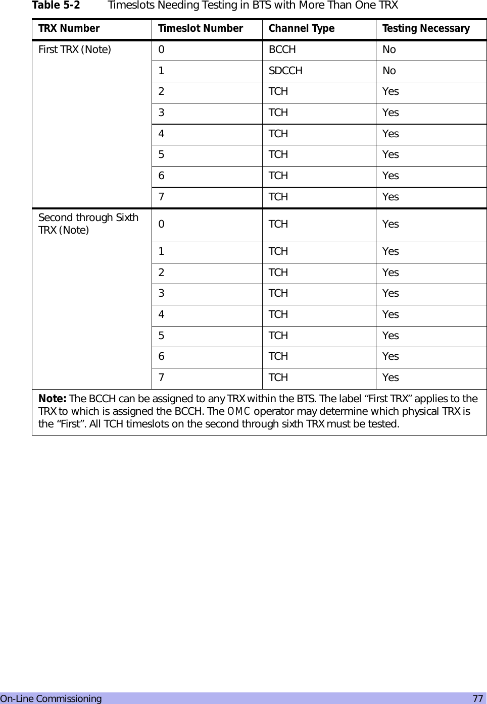
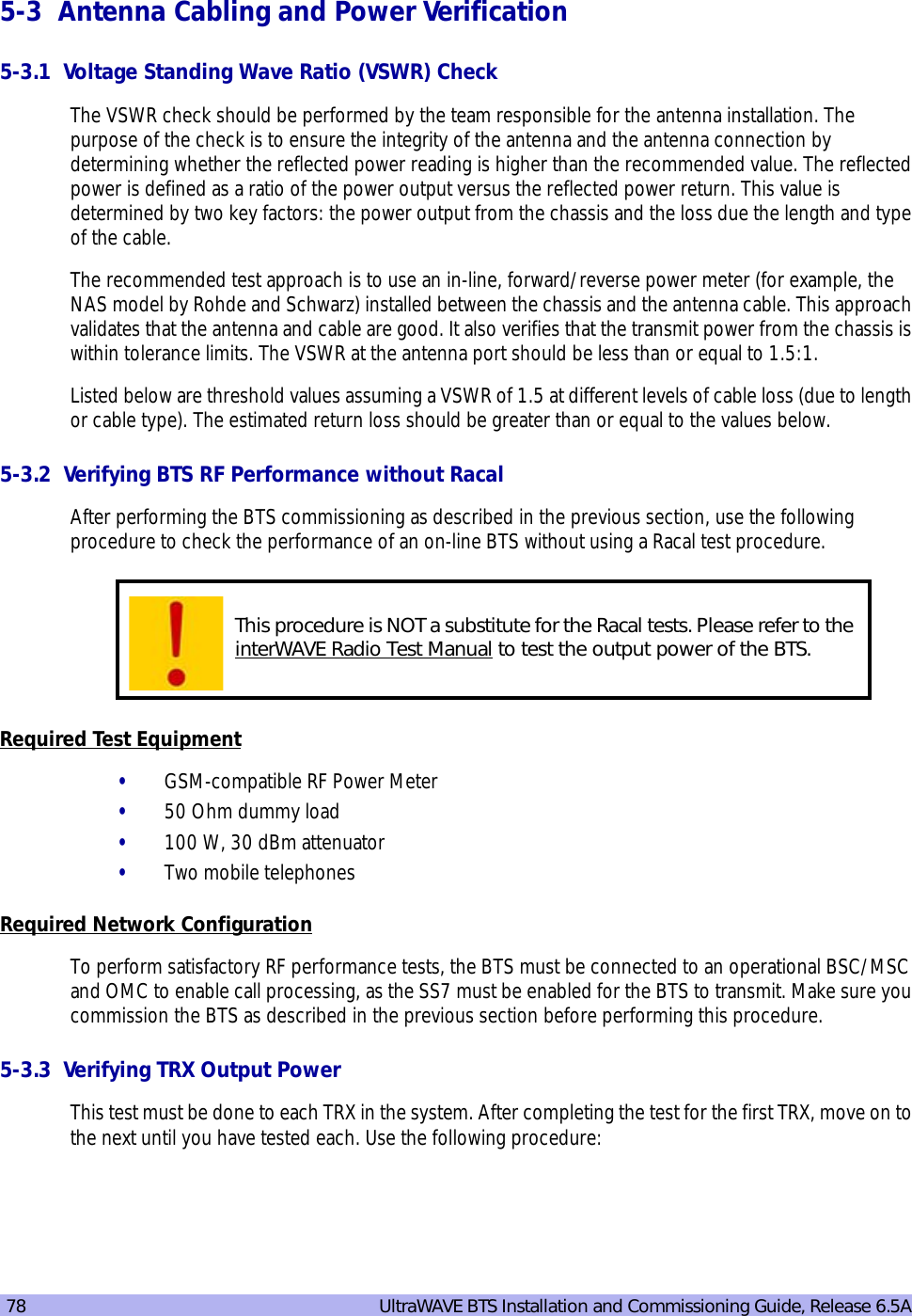
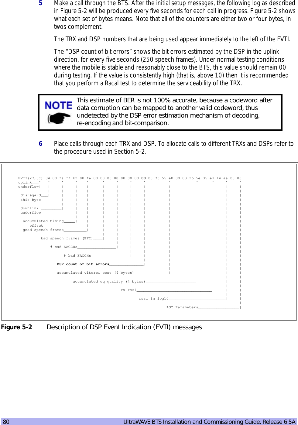
![On-Line Commissioning 791At the OMC, make sure that the BTS is in a locked state.2Disconnect the appropriate antenna cable from cabinet. This cable will correspond to the TRX which you are testing. See Section 2-6 for additional RF cabling information.3Ensure that the OMC is configured so that the BCCH is on the TRX you are testing. 4Connect the dummy load to the “out” port of the RF Power Meter.5For each TRX, connect the “in” port of the RF Power Meter to the RFD as follows.6At the OMC, change the BTS state to unlocked.7Note the output power of the TRX on the power meter; this will be displayed in either Watts or dBm. 8Complete these steps for each TRX in turn until you have tested them all.If a TRX falls out of the margins, interWAVE recommends that you perform a Racal test to determine the serviceability of the TRX.5-3.4 RX BER MeasurementsThe objectives of this test are to verify the performance of the Receive path of the BTS and the operation of the RX module in the TRX. Before these tests can take place the BTS must be returned to its original “on air” working state with call processing possible.1From an Xterm window on the OMC, telnet to the BSC controlling the BTS to be tested, or alternatively connect directly to the BSC with the Craft PC.2From the BSC prompt find the IP address of the BTS by typing:HD:bsc-> ifShow “ppp” [ENTER]A list of PPP connections will then be displayed. Look for the IP address of the BTS you will be testing. The last number of the “192.168.5.x” address relates to the BtsMgr number of the BTS.3From the BSC prompt type the following to connect to the BTS:HD:bsc-> rlogin “192.168.5.x” [ENTER]If this is successful you will receive the bts-> prompt.4From the BTS prompt type the following to activate the RX BER logging:bts-> log_none [ENTER] bts-> log_lapdm [ENTER] bts-> setdontarray 0x43,0 [ENTER]The procedure for BCCH reconfiguration can be found in the Network Configuration section of the WAVEView OMC Configuration Guide.](https://usermanual.wiki/ADC-Telecommunications/AUAC85/User-Guide-307193-Page-91.png)