ADC Telecommunications CX-DS3-53G Point to Point DSX3 / IP Transceiver User Manual interWave WaveNet Link CX
ADC Telecommunications Inc. Point to Point DSX3 / IP Transceiver interWave WaveNet Link CX
UserManual.wiki
>
ADC Telecommunications
>
CX DS3 53G User Manual
User Manual
Navigation menu
Upload a User Manual
Namespaces
Wiki Guide
HTML
PDF
Info
Views
User Manual
Discussion / Help
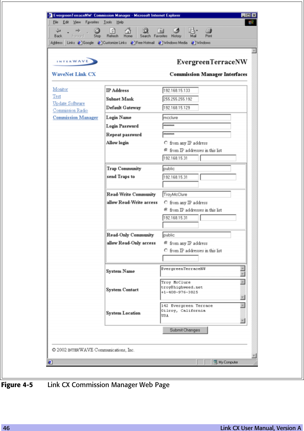
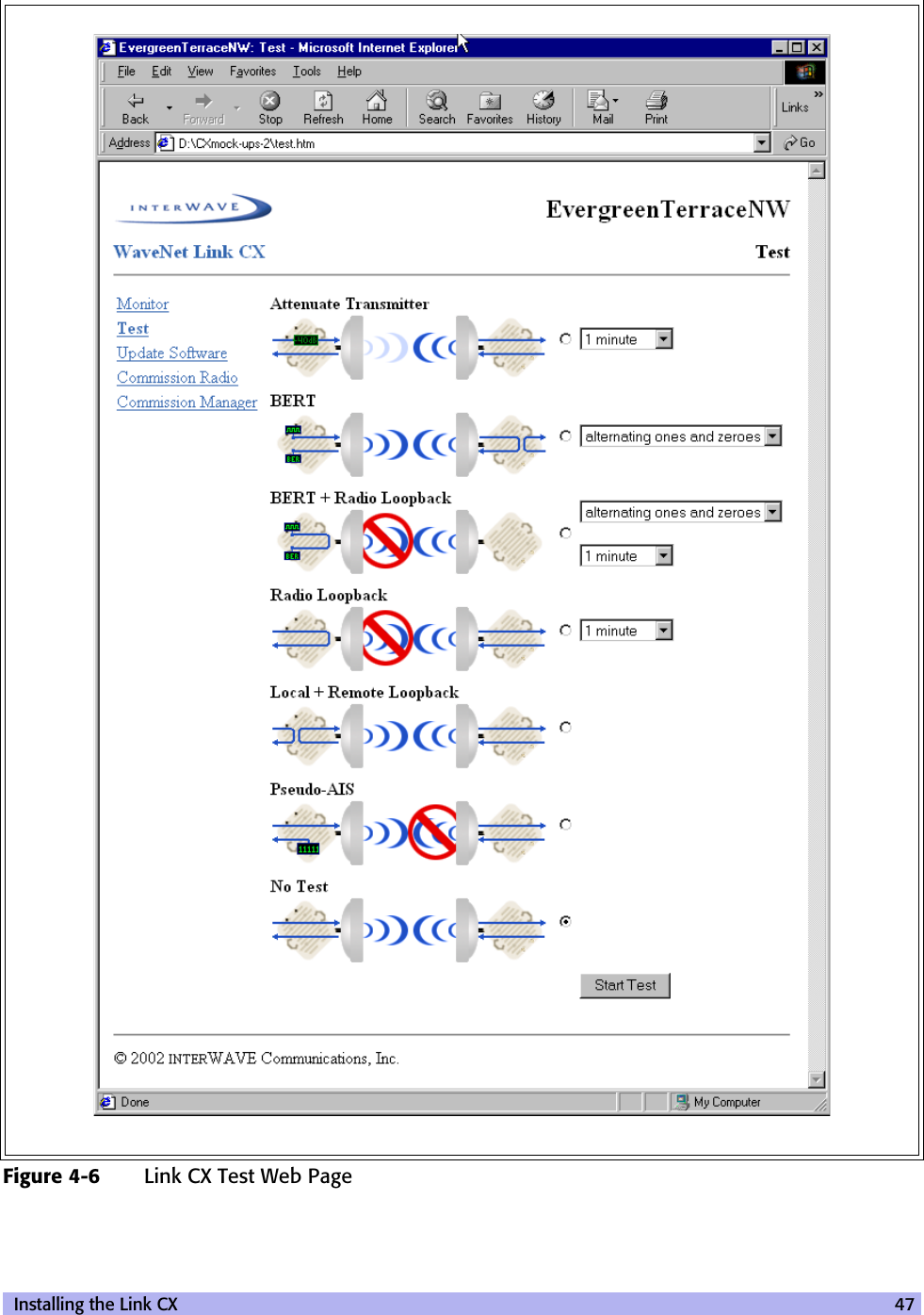
Navigation

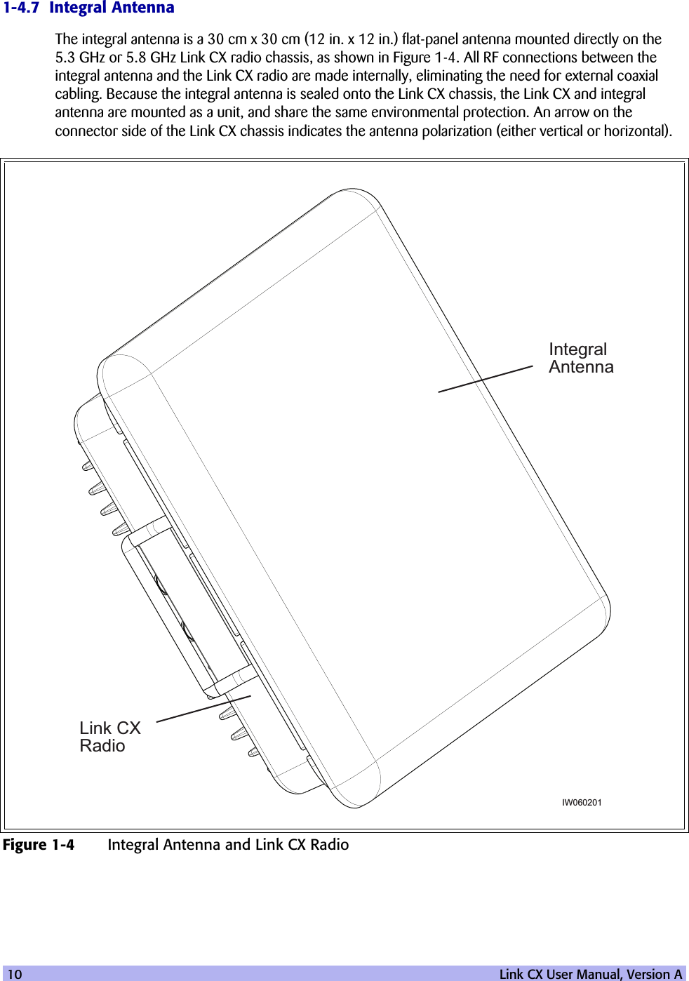
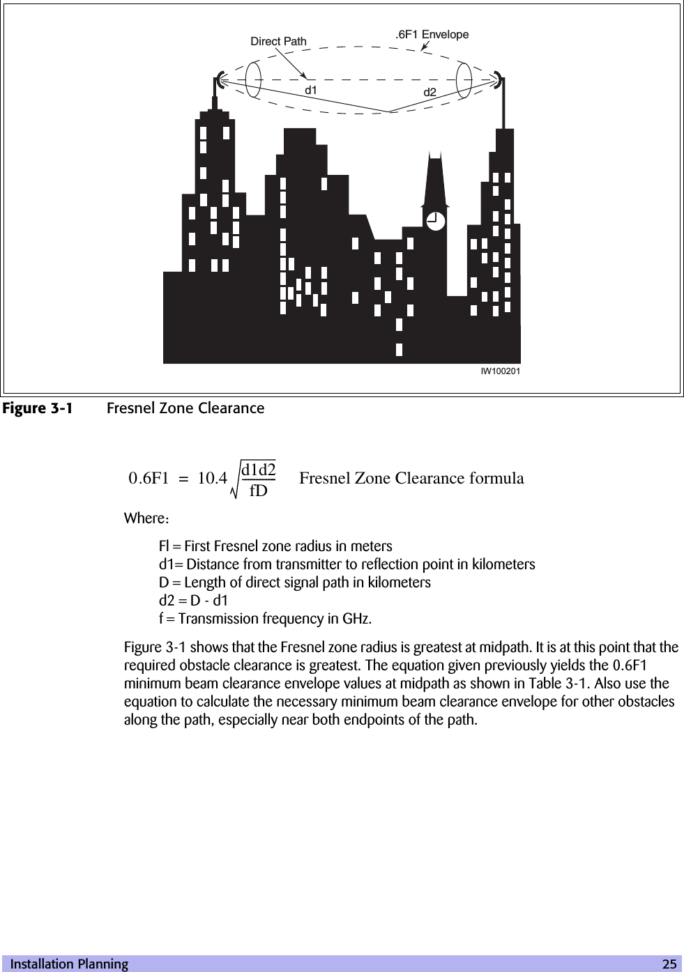
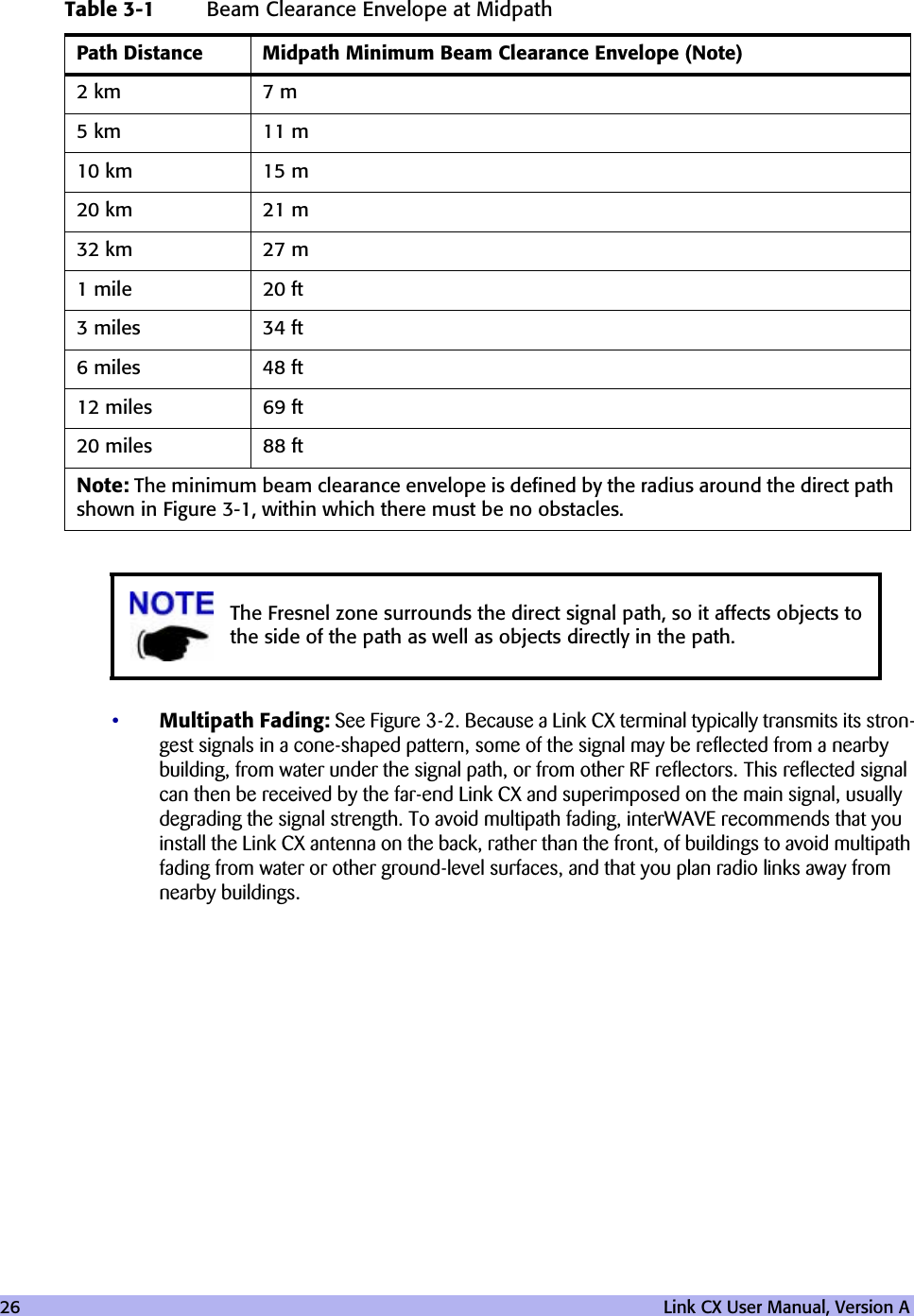
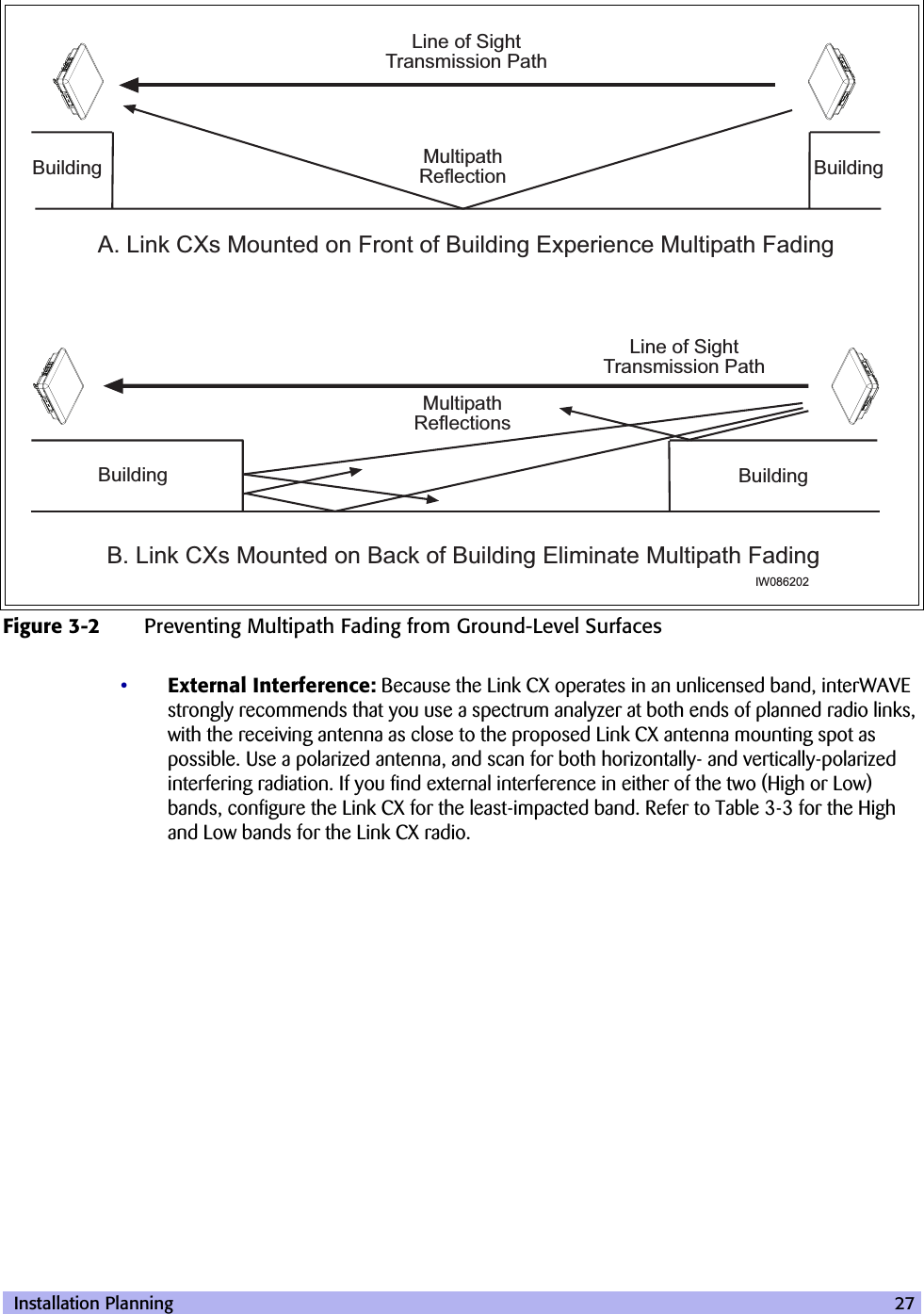
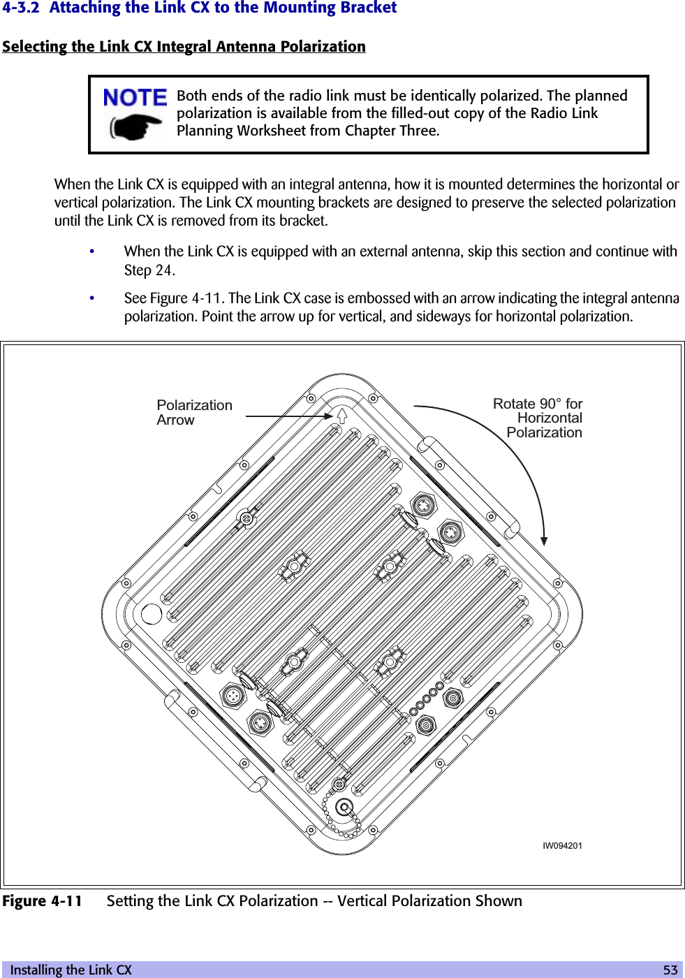
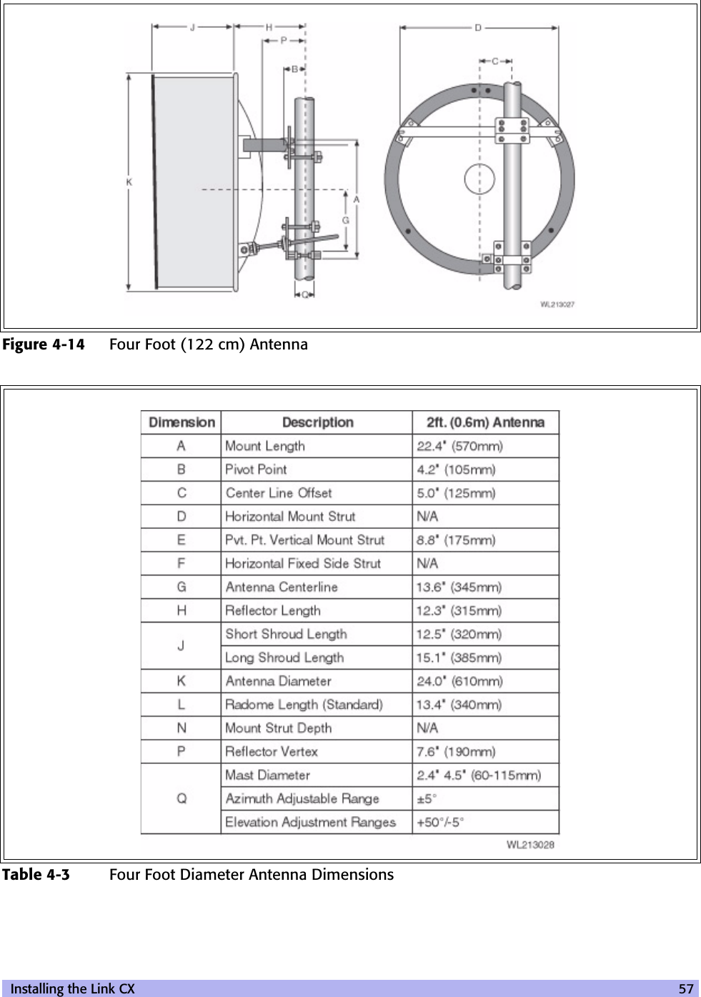
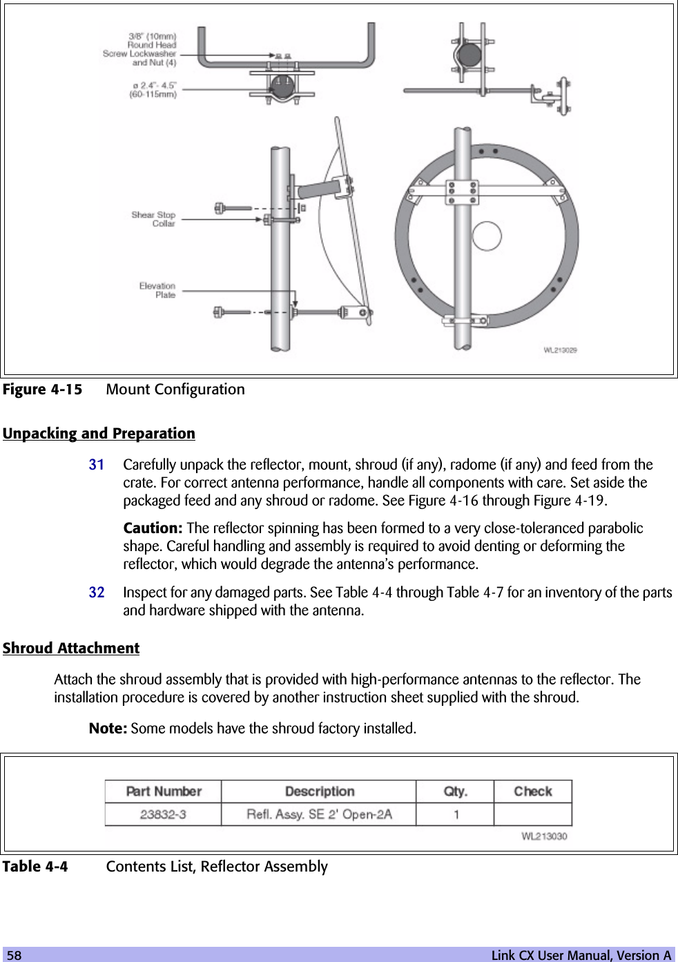
![xvConventions Used in this ManualThe following type and style conventions are used in this manual:sssssss ssss ssssss ssssssssss sssssssssss ssssss ssss ssssss sssssssssss ssssssssss sssssssssss ssssss ssssssssss sssssssssss ssssssssss sssss ssss ssssss ssssssssss sssssssssss ssssss ssss ssssss sssssssssss ssssssssss sssssssssss ssssss ssss ssssss sssssssssss ssssssssss ssssss ssss sssssss ssssssssss sssssssssss ssssss ssss ssssss sssssssssss ssssssssss ssssssssss sssssss ssss ssssss sssssssssss ssssssssss ssssss ssss sssssss ssssssssss ssssssssss sssssssssss ssssss sssssssssss ssssssssss ssssssssss sssssss ssss ssssss ssssssssss sssssssssss ssssss ssss sssssss ssssssssss ssssssssss sssssssssss ssssss ssss ssssss sssssssssss ssssssssss ssssss sssss ssssss ssssssssssssssss ssss ssssss ssssssssss sssssssssss ssssss ssss ssssss sssssssssss ssssssssss sssssssssss ssssss ssssssssss sssssssssss ssssssssss sssss ssss ssssss ssssssssss sssssssssss ssssss ssss ssssss sssssssssss ssssssssss sssssssssss ssssss ssss ssssss sssssssssss ssssssssss ssssss ssss sssssss ssssssssss sssssssssss ssssss ssss ssssss sssssssssss ssssssssss ssssssssss sssssss ssss ssssss sssssssssss ssssssssss ssssss ssss sssssss ssssssssss ssssssssss sssssssssss ssssss sssssssssss ssssssssss ssssssssss sssssss ssss ssssss ssssssssss sssssssssss ssssss ssss sssssss ssssssssss ssssssssss sssssssssss ssssss ssss ssssss sssssssssss ssssssssss ssssss sssss ssssss ssssssssssssssss ssss ssssss ssssssssss sssssssssss ssssss ssss ssssss sssssssssss ssssssssss sssssssssss ssssss ssssssssss sssssssssss ssssssssss sssss ssss ssssss ssssssssss sssssssssss ssssss ssss ssssss sssssssssss ssssssssss sssssssssss ssssss ssss ssssss sssssssssss ssssssssss ssssss ssss sssssss ssssssssss sssssssssss ssssss ssss ssssss sssssssssss ssssssssss ssssssssss sssssss ssss ssssss sssssssssss ssssssssss ssssss ssss sssssss ssssssssss ssssssssss sssssssssss ssssss sssssssssss ssssssssss ssssssssss sssssss ssss ssssss ssssssssss sssssssssss ssssss ssss sssssss ssssssssss ssssssssss sssssssssss ssssss ssss ssssss sssssssssss ssssssssss ssssss sssss ssssss ssssssssssssssss ssss ssssss ssssssssss sssssssssss ssssss ssss sssssss ssssssssss ssssssssss sssssssssss ssssss ssssssssss sssssssssss ssssssssss sssss ssss ssssss ssssssssss sssssssssss ssssss ssss ssssss sssssssssss ssssssssss sssssssssss ssssss ssss ssssss sssssssssss ssssssssss ssssss sssss ssssss ssssssssss sssssssssss ssssss ssss ssssss sssssssssss ssssssssss sssTable 3 Conventions Used in This ManualConvention MeaningBody text Used for regular body textBold Indicates a menu or button choiceCommand Indicates computer generated text and promptsUser Input Indicates user input<hostname> In command syntax, indicates user-specified command line parameters<variable> In body text, indicates user-specified command line parameters[BRACKETS] Indicates a key on the keyboard or instrumentProvides relevant additional informationProvides important warning information that may affect operation of or maybe a potential threat to the systemUsed to tell the reader to STOP what they are doing and to read important instructions that are vital to prevent equipment or software damage](https://usermanual.wiki/ADC-Telecommunications/CX-DS3-53G/User-Guide-259247-Page-15.png)