ADC Telecommunications DAS8M-4IDEN-W In-building distributed antenna system User Manual J bonnie john front cover eps
ADC Telecommunications Inc. In-building distributed antenna system J bonnie john front cover eps
UserManual.wiki
>
ADC Telecommunications
>
DAS8M-4IDEN-W User Manual
>
Part 6 Users Manual
Contents
1.
Part 1 users manual
2.
Part 2 users manual
3.
Part 3 Users Manual
4.
Part 4 Users Manual
5.
Part 5 Users Manual
6.
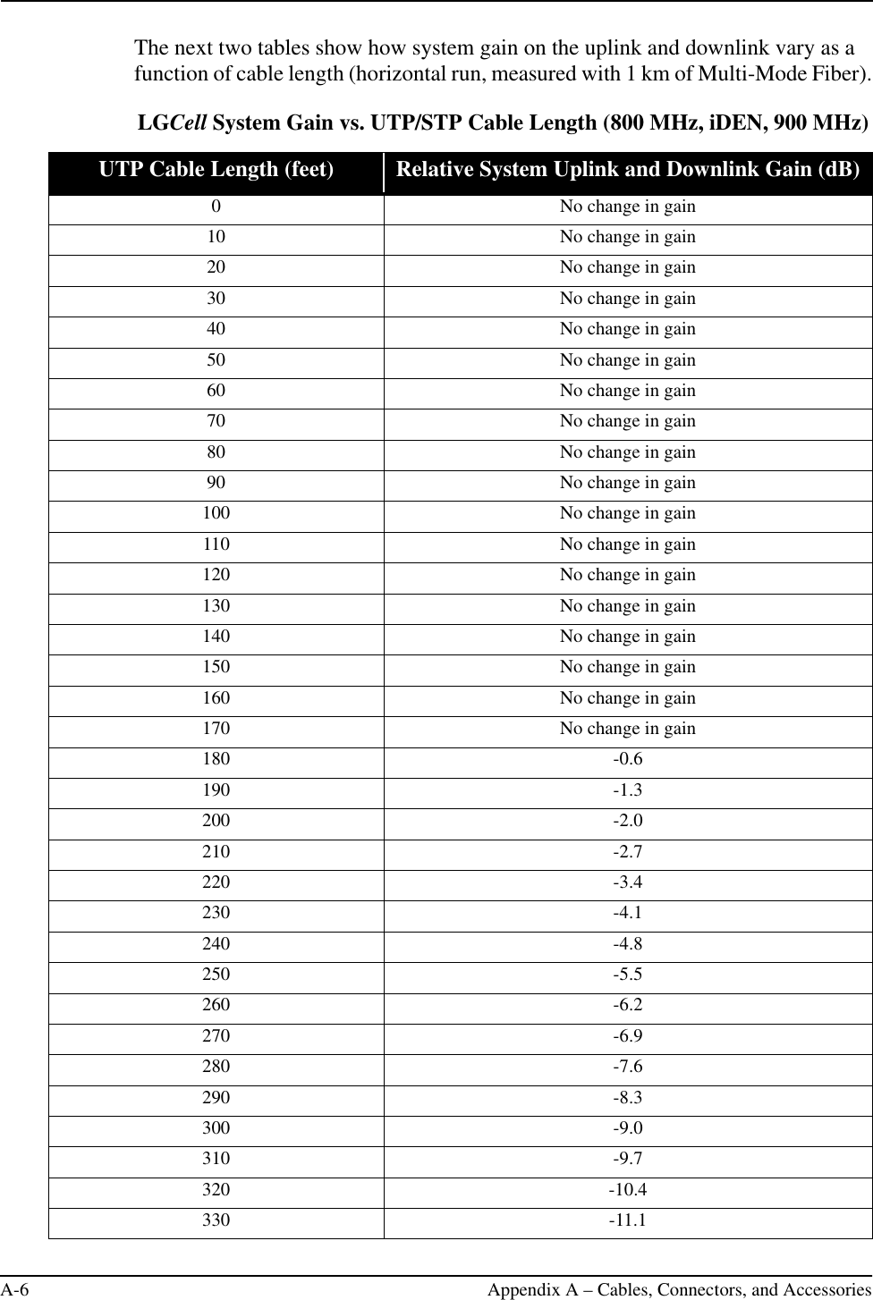
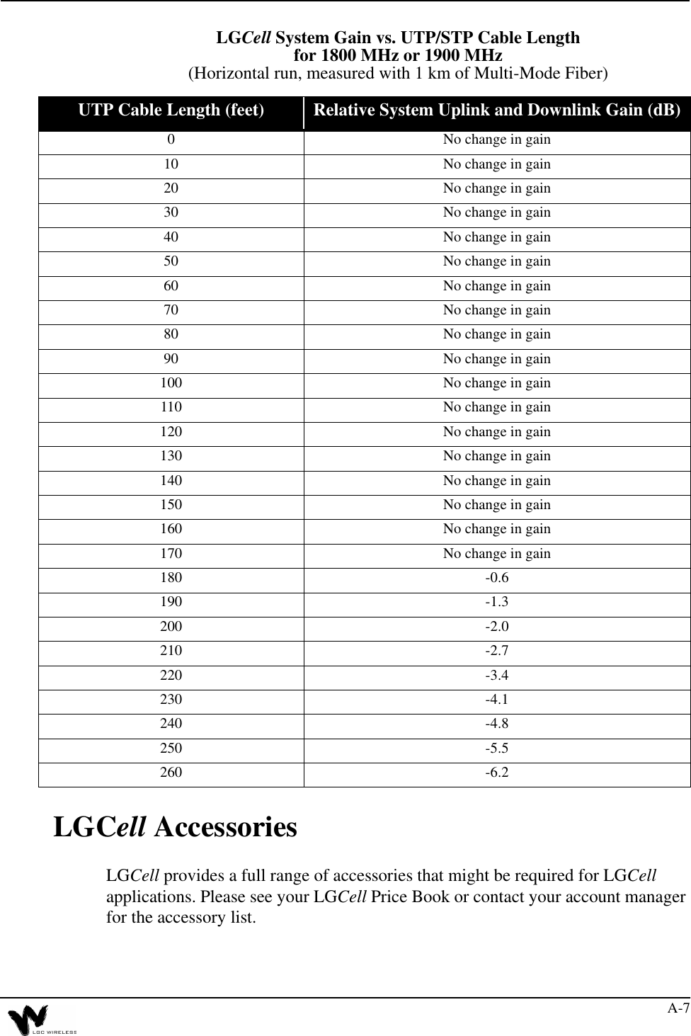
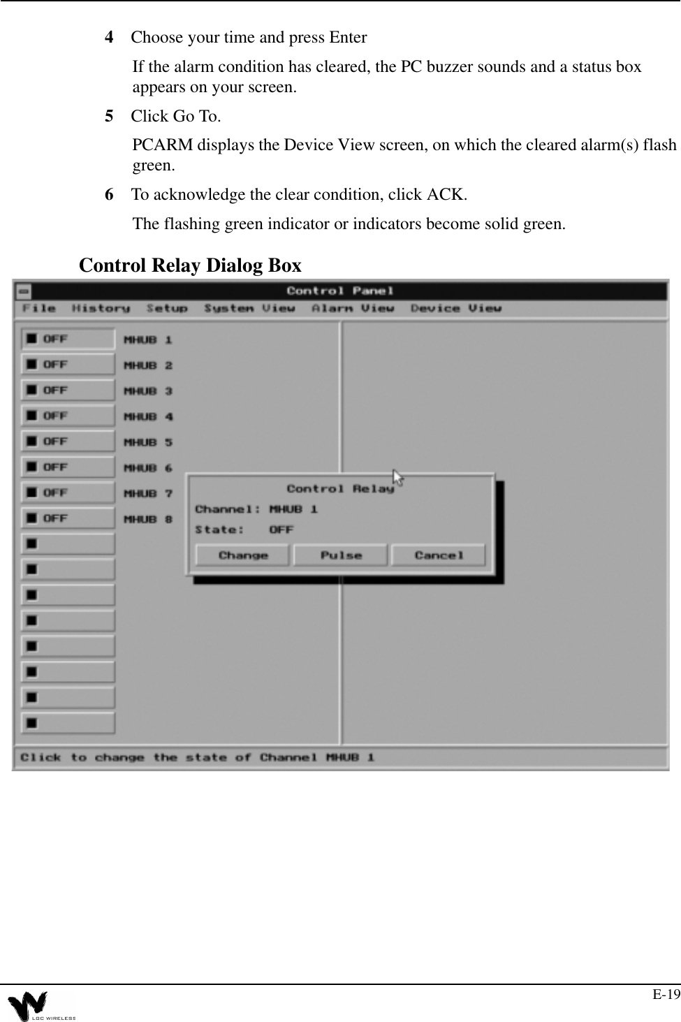
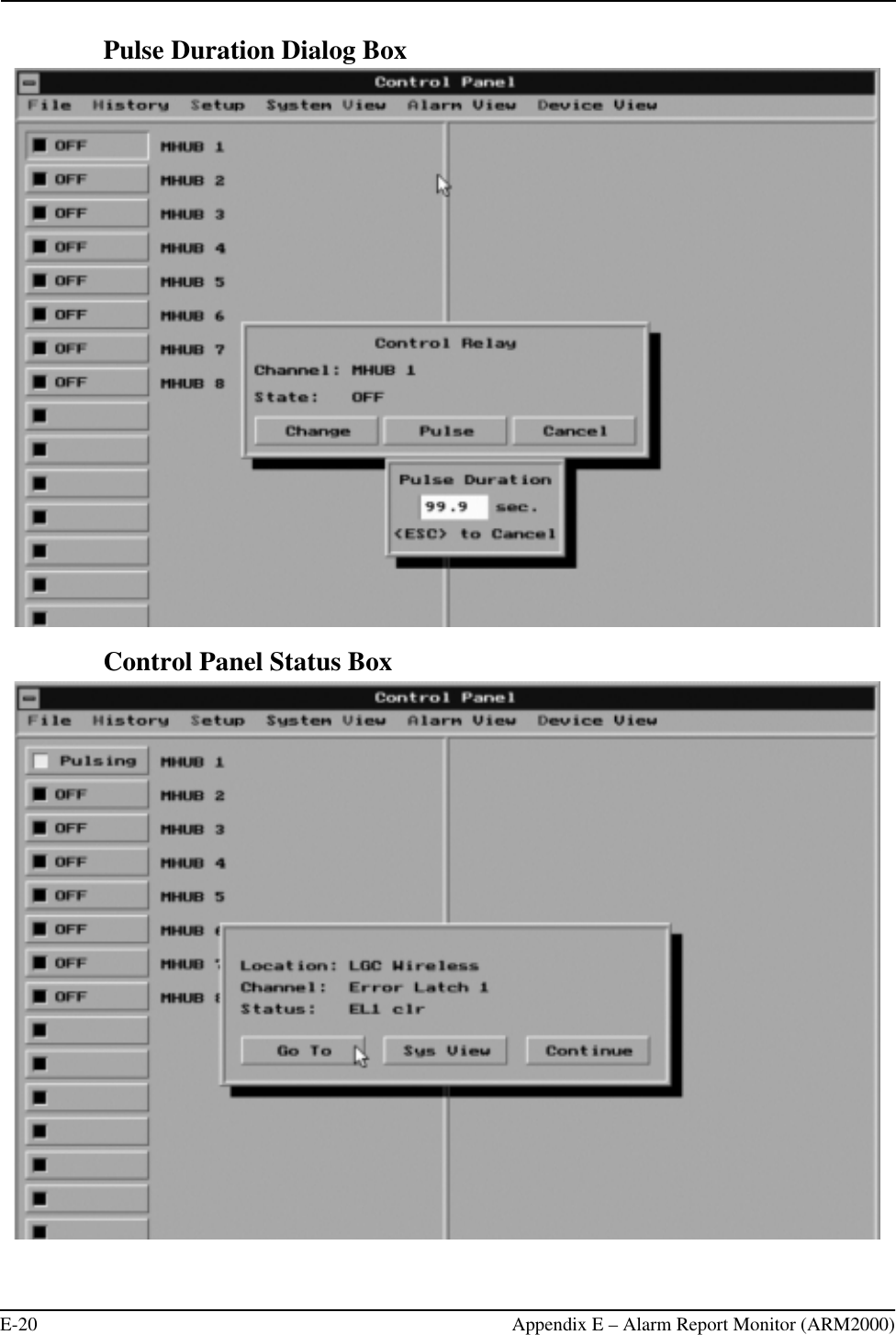
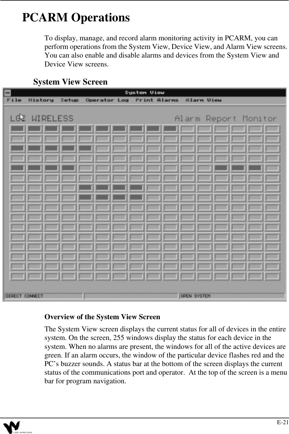
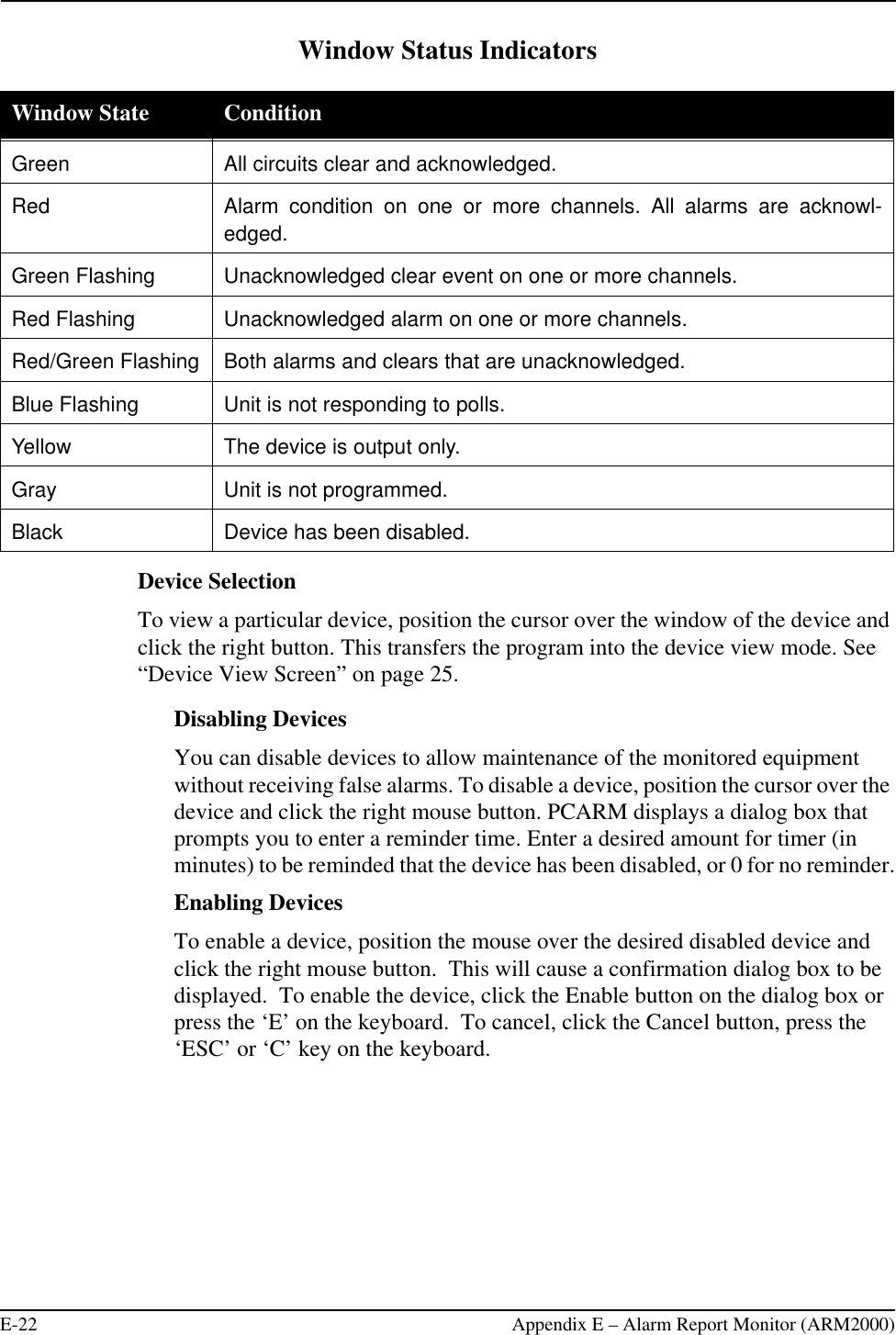
Part 6 Users Manual
7.
Radiation Warning
8.
Antenna gain sentence
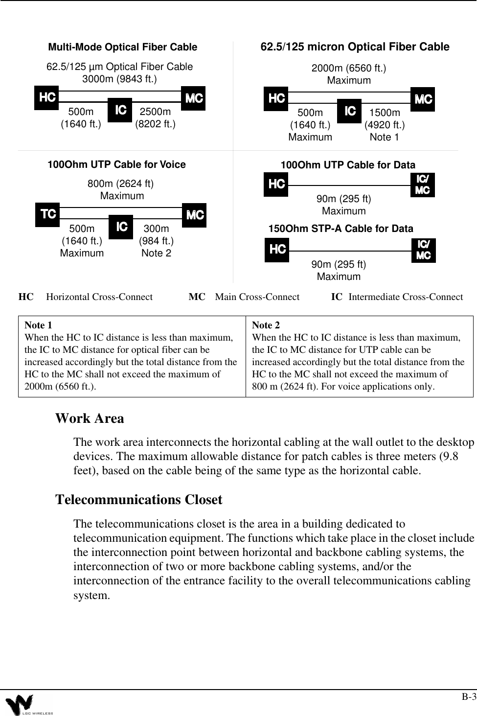
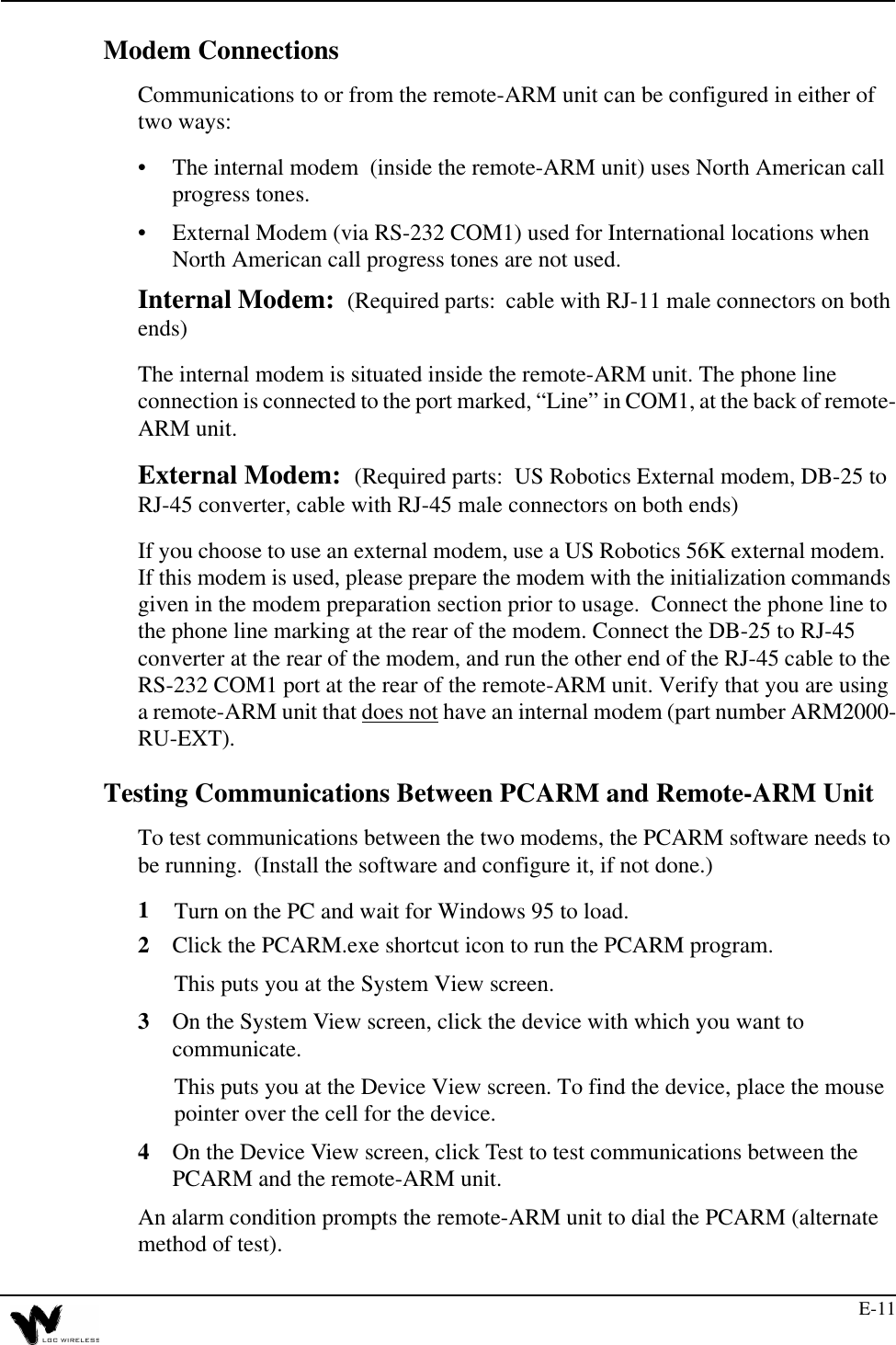
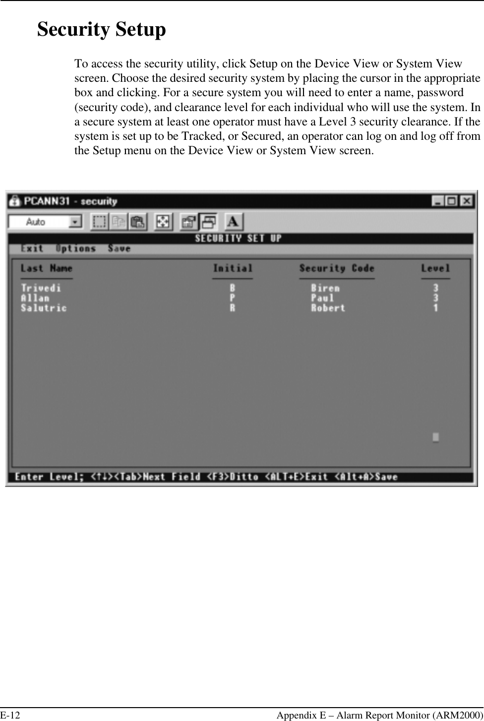
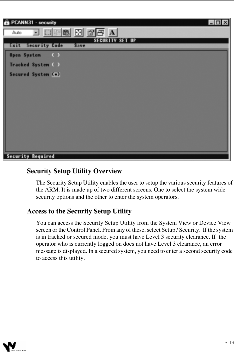
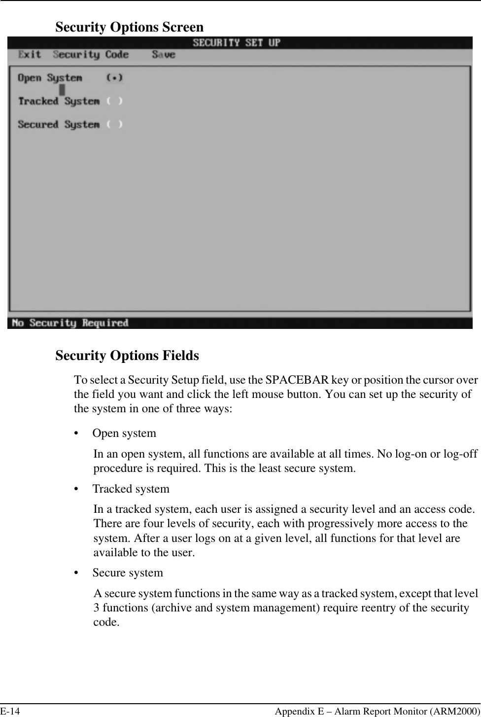
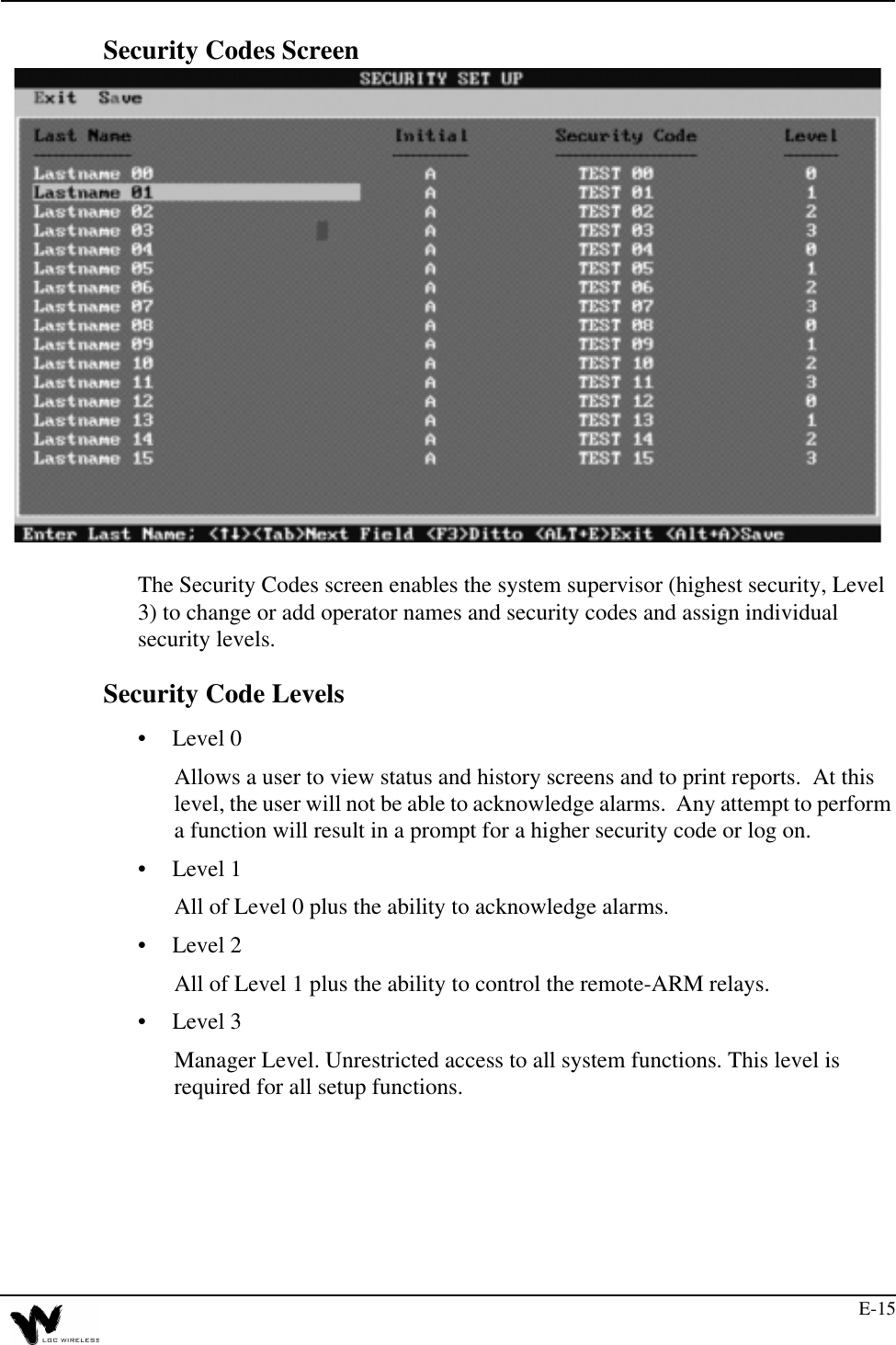
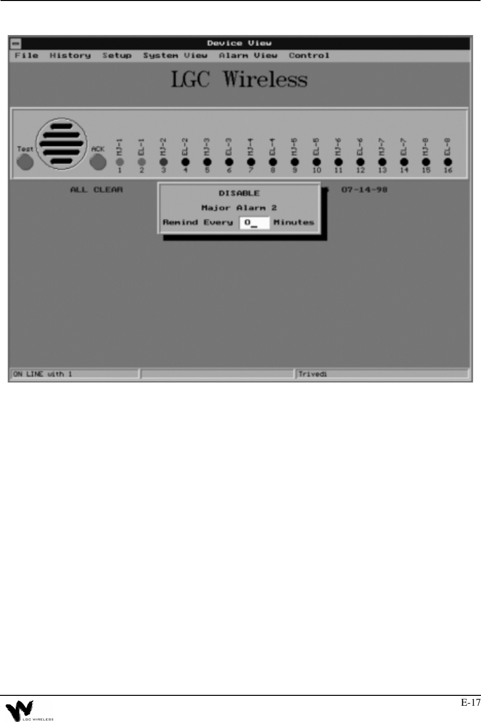
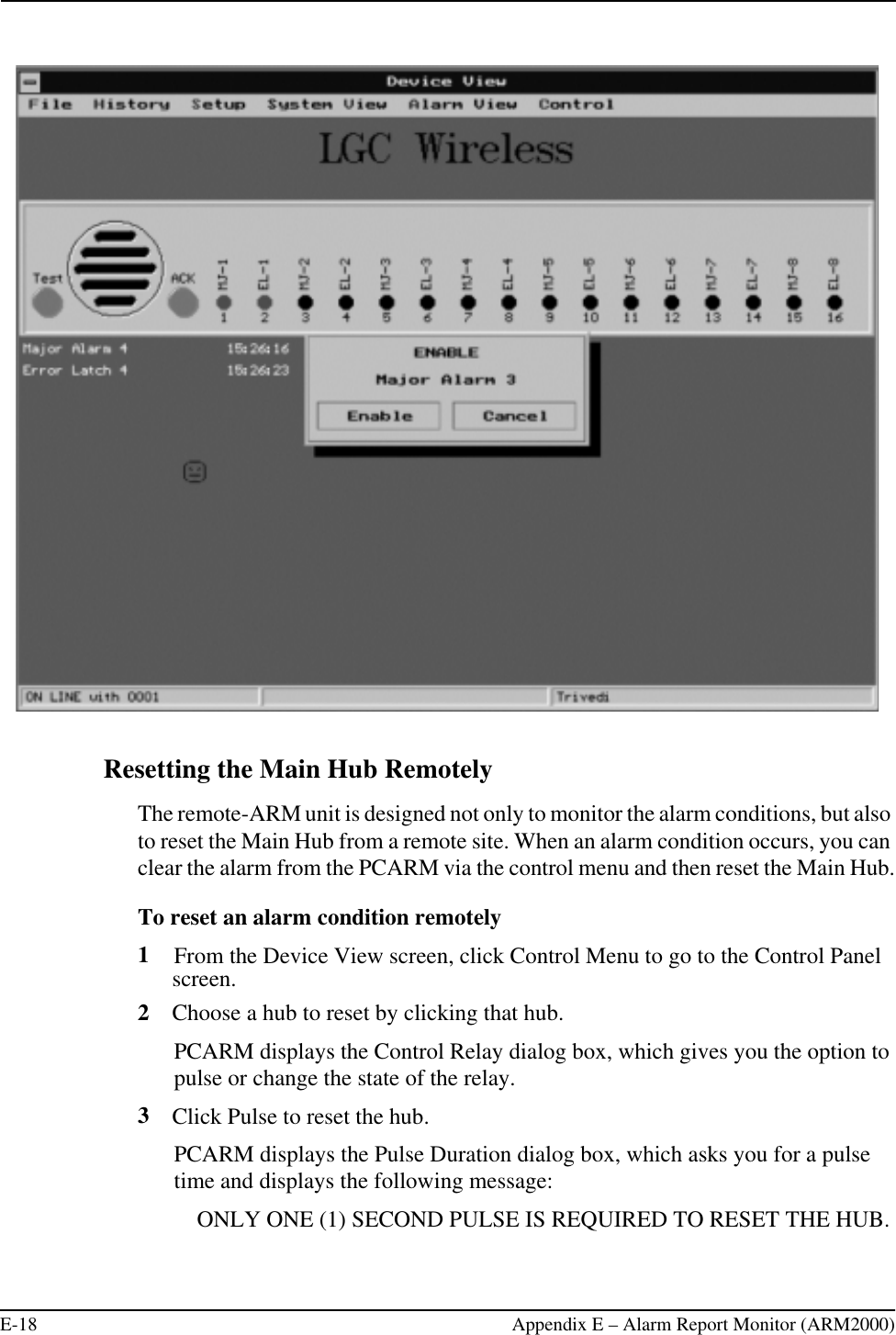
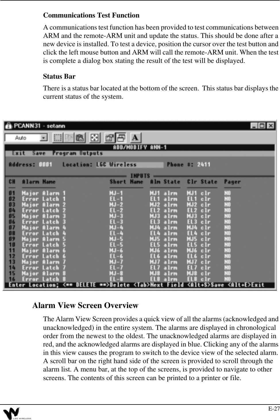
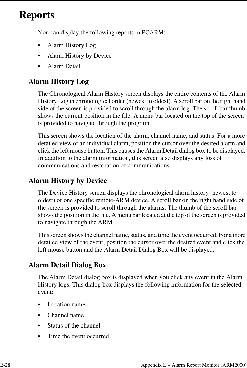
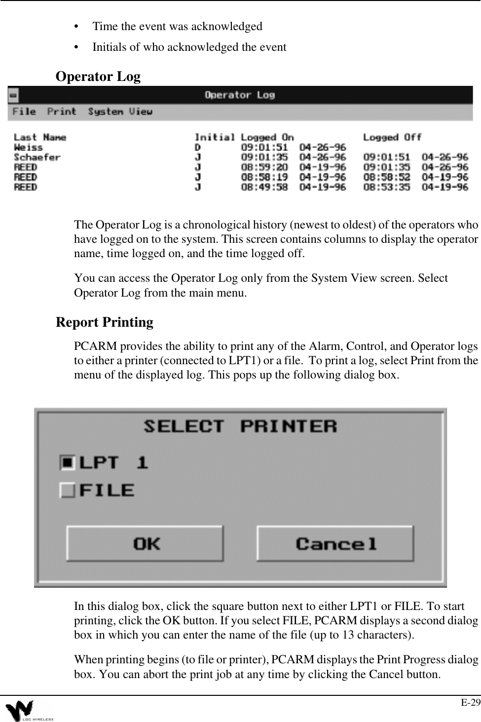
Part 6 Users Manual
Navigation menu
Upload a User Manual
Namespaces
Wiki Guide
HTML
PDF
Info
Views
User Manual
Discussion / Help
Navigation