ADC Telecommunications DLC1902A Digivance 1900 MHz 20 Watt System User Manual 75158
ADC Telecommunications Inc Digivance 1900 MHz 20 Watt System 75158
Contents
manual 4
ADCP-75-158 • Preliminary Issue A • June 2003 • Section 3: Host Unit Installation
Page 3-8
© 2003, ADC Telecommunications, Inc.
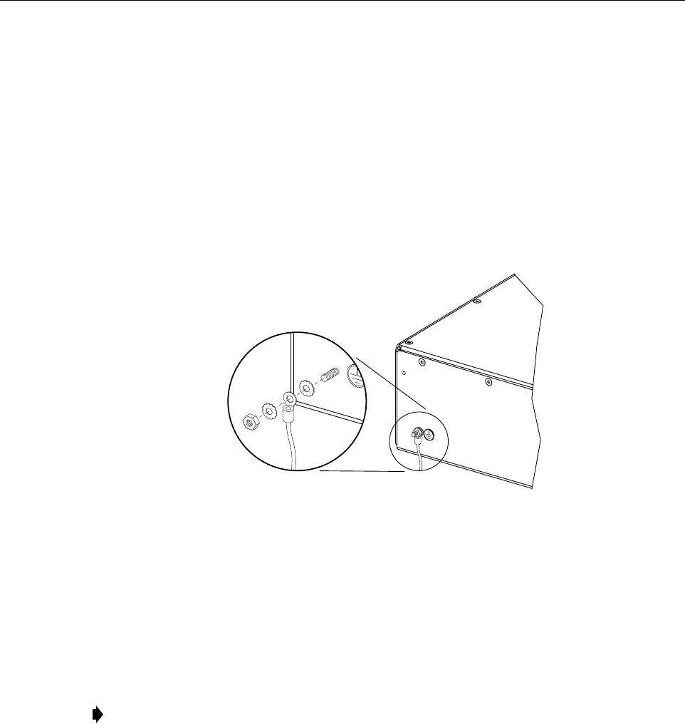
5 CHASSIS GROUND CONNECTION
A stud is provided on the rear side of the chassis for connecting a grounding wire to the chassis.
Use the following procedure to connect the grounding wire to the chassis and to route the
grounding wire to an approved earth ground source.
1. Obtain a length of #18 AWG (1.00 mm) insulated stranded copper wire for use as a
chassis grounding wire.
2. Terminate one end of the wire with a ring terminal.
3. Locate the chassis ground stud at the rear of the HU as shown in Figure 3-7.
Figure 3-7. Chassis Ground Stud
4. Attach the ring end of the wire to the chassis ground stud (see Figure 3-7).
5. Route the free end of the chassis grounding wire to an approved (per local code or
practice) earth ground source.
6. Cut the chassis grounding wire to length and connect it to the approved ground source as
required by local code or practice.
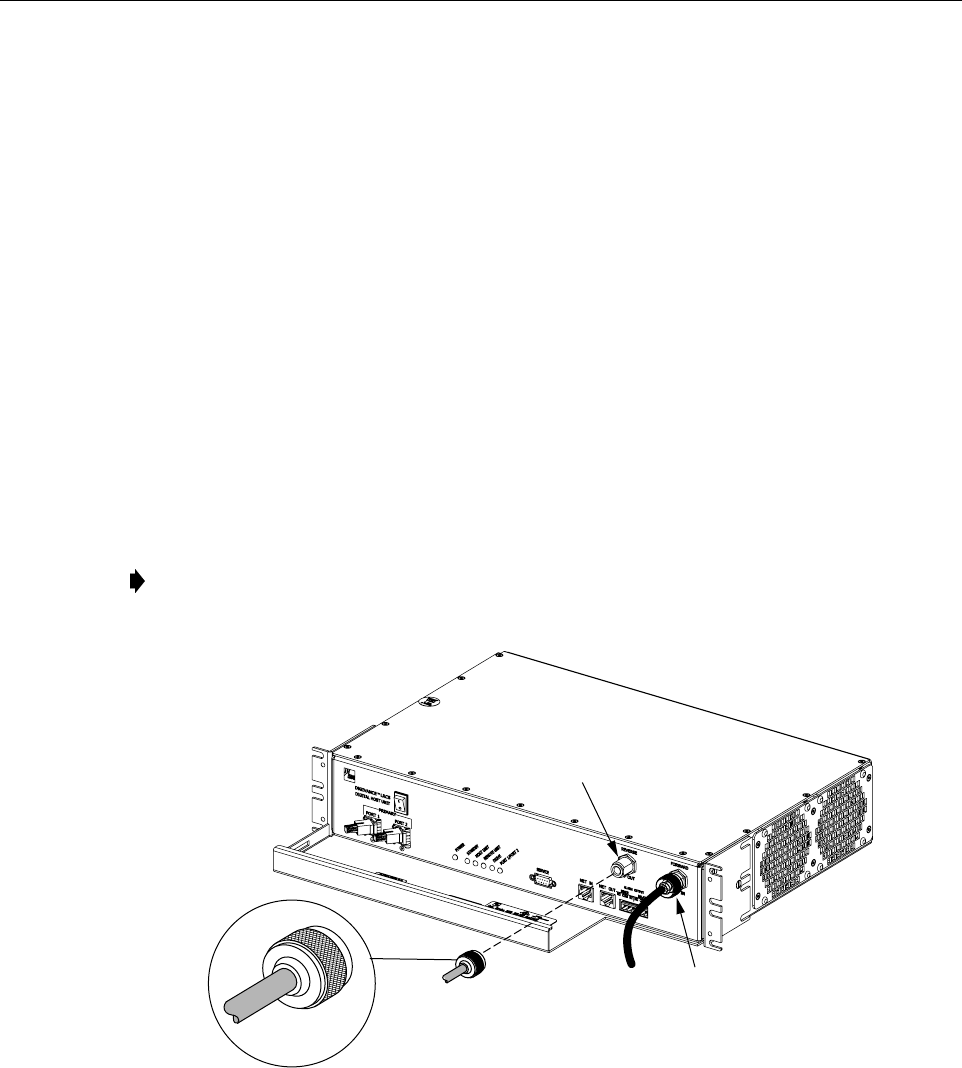
6 COAXIAL CABLE CONNECTIONS
The RF interface between the HU and the BTS is supported through two N-type female
connectors mounted on the HU front panel. One connector provides the coaxial cable
connection for the forward path (downlink) signal and the other connector provides the coaxial
cable connection for the reverse path (uplink) signal.
In most installations, it is usually necessary to insert some attenuation in the forward path link
between the HU and the BTS. A signal level that is greater than –9 dBm will overdrive and
Note: Be sure to maintain reliable grounding. Pay particular attention to ground source
connections.
16169-A
FCC ID: F8I-DLC1902A
ADCP-75-158 • Preliminary Issue A • June 2003 • Section 3: Host Unit Installation
Page 3-9
© 2003, ADC Telecommunications, Inc.
possibly damage the HU receiver. Refer to Section 4, Subsection 2.3, before completing the
forward path connection at the BTS. If the Conditioning Panel or Duplexing Panel is required,
refer to the Digivance 800 and 1900 MHz Interface Panels User Manual (ADCP-75-147) for the
installation procedures. The HU should be mounted as close as possible to the BTS to minimize
cable losses. Use the following procedure to route and connect the forward and reverse path
coaxial cables to the HU:
1. Obtain the required lengths of high performance, flexible, low loss 50-ohm coaxial
communications cable (RG-400 or equivalent) for all coaxial connections.
2. Route the forward and reverse path coaxial cables between the HU and the BTS interface
(per system design plan) and cut to the required length. Allow sufficient slack for dressing
and organizing cables at the HU and for installing an external attenuator in the forward
path link.
3. Terminate each cable with an N-type male connector following the connector supplier’s
recommendations.
4. Connect the forward path cable to the FORWARD RF IN connector on the HU front
panel as shown in Figure 3-8.
Figure 3-8. Forward and Reverse Path Coaxial Cable Connections
5. Connect the reverse path cable to the REVERSE RF OUT connector on the HU front
panel (see Figure 3-8).
6. Dress and secure cables at the HU.
7. Complete all remaining coaxial connections as specified in the system design plan.
Note: Do not connect the forward path cable at the BTS until the composite forward path
RF signal level is measured and the amount of attenuation required is determined.
18655-A
TYPE-N MALE
CONNECTOR
FORWARD RF IN
CONNECTOR
(FORWARD PATH)
REVERSE
RF OUT CONNECTOR
(REVERSE PATH)

ADCP-75-158 • Preliminary Issue A • June 2003 • Section 3: Host Unit Installation
Page 3-10
© 2003, ADC Telecommunications, Inc.
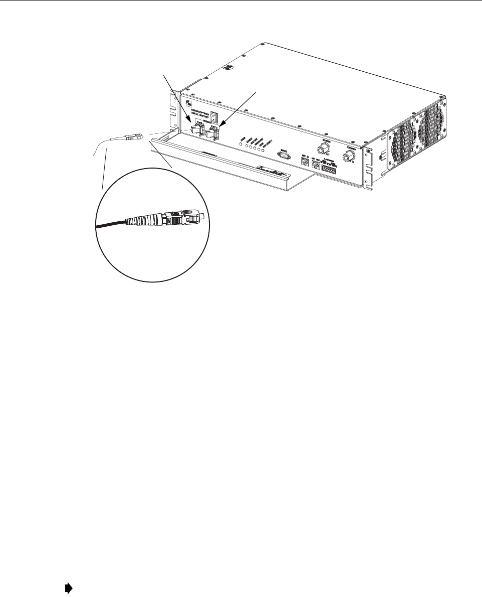
7 OPTICAL CONNECTIONS
The optical interface between the HU and the RU is supported by two optical ports. Each optical
port consists of an SC optical adapter which is mounted on the HU front panel. Port 1 provides
the optical fiber connection for the forward path (downlink) signal. Port 2 provides the optical
fiber connection for the reverse path (uplink) signal.
The optical connections are dependent on whether or not a WDM host module (accessory) or
CWDM host module (accessory) is installed. If the installation does not include either a WDM or
CWDM module, proceed to Section 7.1 for the optical connections procedure. If the installation
includes a WDM module, proceed to Section 7.2 for the optical connections procedure. If the
installation includes a CWDM module, refer to the Digivance System Coarse Wavelength
Division Multiplexer User Manual (ADCP-75-142) for the optical connection procedure.
7.1 Optical Connections Without WDM or CWDM system
Use the following procedure to connect the optical fibers when a WDM or CWDM host module is
not installed with the HU:
1. Obtain two patch cords that are of sufficient length to reach from the HU to the fiber
distribution panel.
2. Designate one of the patch cords as the forward path link and the other as the reverse
path link and attach an identification label or tag next to each connector.
3. Remove the dust caps from the HU optical ports and from the patch cord connectors that
will be connected to the HU.
4. Clean each patch cord connector (follow patch cord supplier’s recommendations).
5. Insert the connector into the appropriate optical port as shown in Figure 3-9.
6. Route the patch cords from the HU to the fiber distribution panel.
Danger: This equipment uses a Class 1 Laser according to FDA/CDRH rules. Laser radiation
can seriously damage the retina of the eye. Do not look into the ends of any optical fiber. Do not
look directly into the optical transmitter of any unit or exposure to laser radiation may result.
An optical power meter should be used to verify active fibers. A protective cap or hood MUST
be immediately placed over any radiating transmitter or optical fiber connector to avoid the
potential of dangerous amounts of radiation exposure. This practice also prevents dirt particles
from entering the connector.
Note: To protect the optical receivers, insert a 15 dB attenuator in each optical path. After
the optical power has been measured, the attenuator may be resized or removed.
Note: The HU optical adapters are angled to the left. Therefore, patch cords should always
be routed to the HU from the left side of the rack. Routing patch cords to the HU from the
right side of the rack may exceed the bend radius limitations for the optical fiber.
ADCP-75-158 • Preliminary Issue A • June 2003 • Section 3: Host Unit Installation
Page 3-11
© 2003, ADC Telecommunications, Inc.
Figure 3-9. Fiber Optic Cable Connections To Host Unit
7. At the fiber distribution panel, identify the OSP optical fiber terminations that correspond
to the forward and reverse path.
8. Remove the dust caps from the from the patch cord connectors.
9. Clean each patch cord connector (follow patch cord supplier’s recommendations) and then
mate the connector with the appropriate OSP optical fiber termination.
10. Store any excess patch cord slack at the fiber distribution panel.
7.2 Optical Connections With WDM System
Use the following procedure to connect the optical fibers when a WDM module is installed with
the HU:
1. Obtain a patch cord that is of sufficient length to reach from the WDM host module to the
fiber distribution panel.
2. Remove the dust cap from Port 1 or Port 4 on the WDM module and from the patch cord
connector that will be connected to the WDM module.
Note: Each WDM module can support two separate HU’s. The WDM module ports are
numbered from 1 through 6 as shown in Figure 3-10. Ports 1 through 3 are used for HU #1
and Ports 4 through 6 are used for HU #2.
18656-A
PORT 1
(FORWARD PATH)
PORT 2
(REVERSE PATH)
ADCP-75-158 • Preliminary Issue A • June 2003 • Section 3: Host Unit Installation
Page 3-12
© 2003, ADC Telecommunications, Inc.
Figure 3-10. Fiber Optic Connections To WDM Module
3. Clean the patch cord connector (follow connector supplier’s recommendations).
4. Insert the connector into one of the WDM module’s optical ports (port 1 or 4).
5. Route the patch cord from the WDM module to the fiber distribution panel.
6. Identify the OSP optical fiber termination that corresponds to the RU.
7. Remove the dust cap from the OSP cable optical adapter and from the patch cord
connector.
8. Clean the patch cord connector (follow patch cord supplier’s recommendations) and then
mate the connector with the appropriate OSP optical fiber termination.
9. Store any excess patch cord slack at the fiber distribution panel.
10. Remove the dust caps from the HU optical ports and from the WDM pigtails that will be
connected to the HU.
11. Clean each pigtail connector (follow the procedures provided with the WDM module) and
then insert the connector into the appropriate optical port on the HU as shown in
Figure 3-9 and as diagramed in Figure 3-10.
Note: To protect the optical receivers, insert a 15 dB attenuator in each optical path. After
the optical power has been measured, the attenuator may be resized or removed.
Note: The HU optical adapters are angled to the left. Therefore, pigtails should always be
routed to the HU from the left side of the rack. Routing pigtails to the HU from the right
side of the rack may exceed the bend radius limitations for the optical fiber.
PORT 1 PORT 2
HOST UNIT 1 HOST UNIT 2
PORT 1 PORT 2
18657-A
REVERSE
PATH
REVERSE
PATH
FORWARD
PATH
FORWARD
PATH
WAVELENGTH DIVISION
MULTIPLEXER
OSP CABLE
OPTICAL FIBERS
HOST UNIT 1
(BI-DIRECTIONAL FIBER
LINK WITH REMOTE UNIT)
HOST UNIT 2
(BI-DIRECTIONAL FIBER
LINK WITH REMOTE UNIT)
FIBER DISTRIBUTION
PANEL (FDP)
X
X
123 45 6
ADCP-75-158 • Preliminary Issue A • June 2003 • Section 3: Host Unit Installation
Page 3-13
© 2003, ADC Telecommunications, Inc.
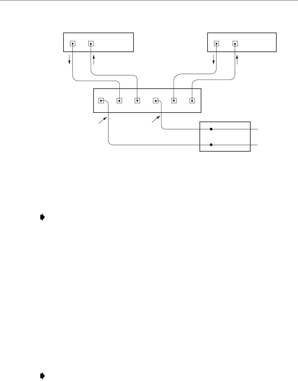
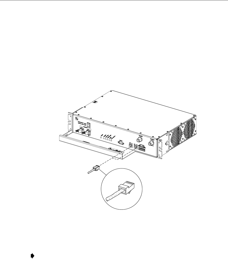
8 CONTROLLER AREA NETWORK CONNECTIONS
Controller Area Network (CAN) interface connections between multiple HU’s are supported by
a pair of RJ-45 jacks. One of the jacks is designated as the NET IN port and the other jack is
designated as the NET OUT port. The CAN interface allows up to 24 HU’s to be connected
together (in daisy-chain fashion) and controlled through a single Digivance EMS computer. A
one meter long cable is available (accessory) for CAN connections. Use the following
procedure to connect CAN interface cables between multiple HU’s:
1. Connect one end of the CAN interface cable (accessory) to either the NET IN or NET
OUT port on HU #1 as shown in Figure 3-11.
Figure 3-11. Controller Area Network Connections
2. Route the CAN interface cable to HU #2 and connect the cable’s free end to the port that is
the logical opposite of the CAN interface connection at HU #1.
3. If a third HU will be connected to the network, connect a second CAN interface cable to
the remaining network port on HU #2.
4. Route the second CAN interface cable to HU #3 and connect the cable’s free end to the
port that is the logical opposite of the CAN interface connection at HU #2.
5. Repeat steps 3 and 4 for each additional HU that is added to the network up to a total of 24
HU’s. A diagram of typical CAN interface connections is shown in Figure 3-12.
Note: Connect OUT to IN and IN to OUT. If connected to the NET OUT port at HU #1,
connect to the NET IN port at HU #2. If connected to the NET IN port at HU #1, connect
to the NET OUT port at HU #2.
18658-A
RJ-45 CONNECTOR
DETAIL
ADCP-75-158 • Preliminary Issue A • June 2003 • Section 3: Host Unit Installation
Page 3-14
© 2003, ADC Telecommunications, Inc.
Figure 3-12. Configuring CAN Connections with Multiple Host Units
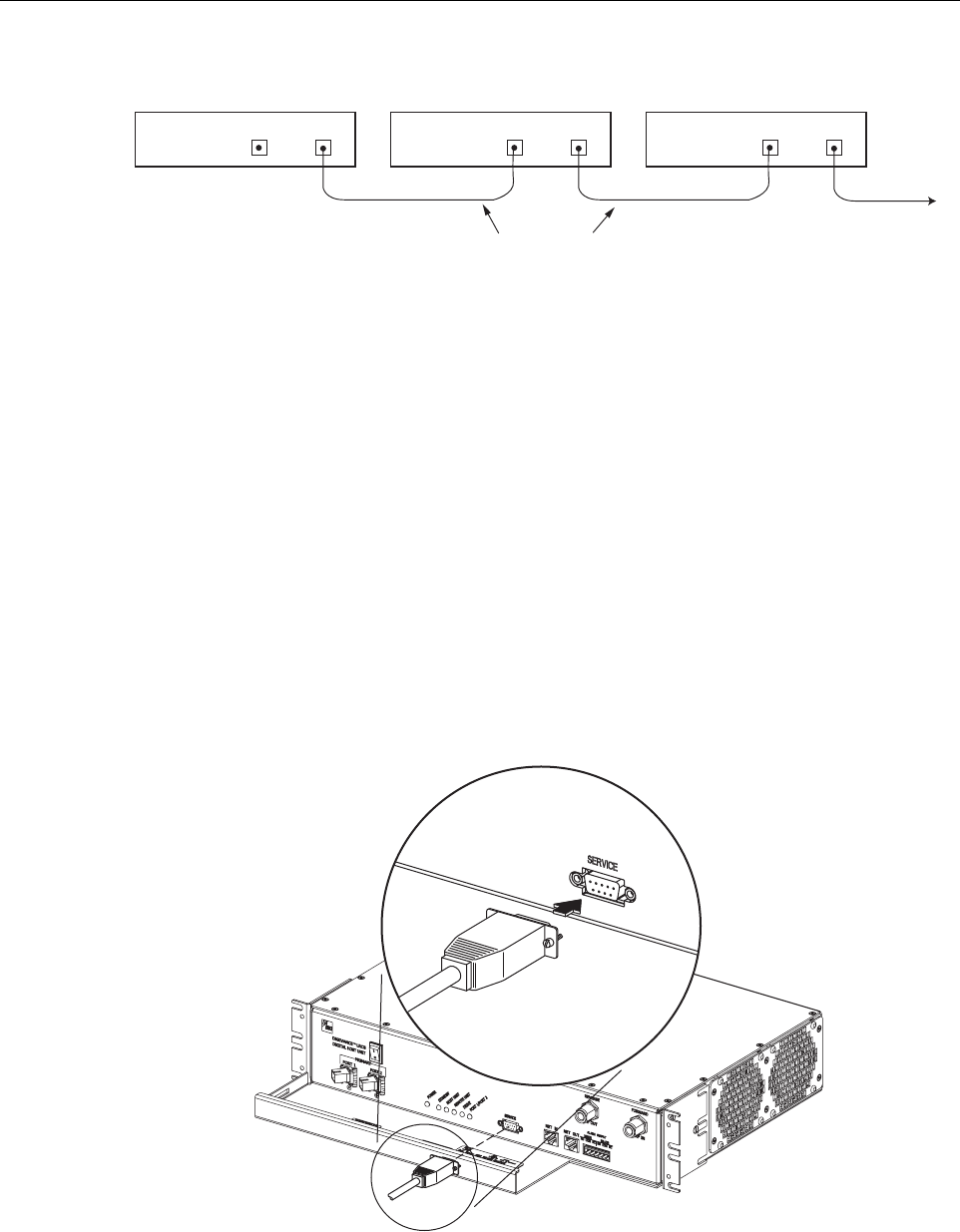
9 EMS COMPUTER CONNECTION
The service interface connection between the HU and the EMS computer is supported by a
single DB-9 female connector. The service connector provides an RS-232 DTE interface. A
three meter long straight-through RS-232 interface cable is available (accessory) for connecting
the EMS computer to the HU. Use the following procedure to install the service interface cable:
1. Connect one end of the service interface cable (accessory) to the SERVICE port as shown
in Figure 3-13.
2. Route the service interface cable to the EMS computer and connect the free end of the
cable to the computer’s RS-232 DCE port. Refer to the user manual provided with the
computer to locate and configure the specified port.
Figure 3-13. Service Interface Connection
HOST UNIT 1 HOST UNIT 2 HOST UNIT 3
NET IN NET OUT NET IN NET OUT NET IN NET OUT
16900-B
CONTROLLER AREA NETWORK
INTERFACE CABLES
TO NEXT HOST UNIT
(NOTE: LAST HOST HAS NO
CONNECTION AT NET OUT)
18659-A
ADCP-75-158 • Preliminary Issue A • June 2003 • Section 3: Host Unit Installation
Page 3-15
© 2003, ADC Telecommunications, Inc.
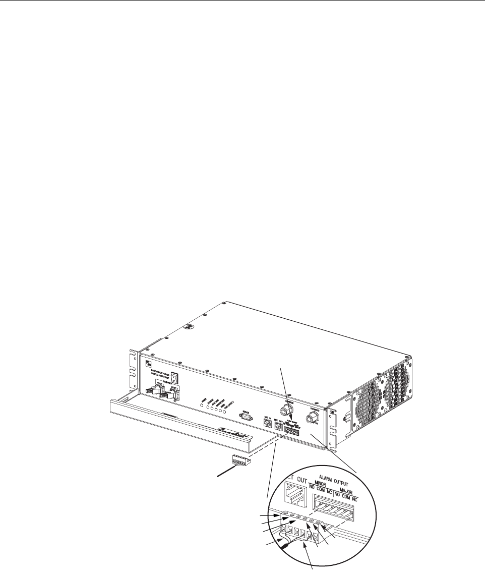
10 EXTERNAL ALARM SYSTEM CONNECTIONS
The alarm interface between the HU and an external alarm system is supported by a six-terminal
plug (with screw-type terminals) that connects to a receptacle mounted on the HU front panel.
The terminal plug provides connections to normally open (NO) and normally closed (NC) dry
type alarm contacts for both major and minor alarms. A category 3 or 5 cable is typically used to
connect the HU to the external alarm system. Use the following procedure to install the alarm
wiring and connect it to the HU:
1. Obtain the required length of category 3 or 5 cable.
2. Route the cable between the HU and the external alarm system (if not already routed) and
then cut to the required length. Allow sufficient slack for dressing and organizing the cable
at the HU.
3. Strip back the outer cable sheath and insulation to expose the wires at both ends of the
cable and strip back 0.2 inches (5 mm) of insulation from each wire.
4. Connect the Major alarm wire pair to the MAJOR COM/NC or MAJOR COM/NO
terminals (whichever is required by the external alarm system) on the HU alarm terminal
connector (supplied with HU) as shown in Figure 3-14.
Figure 3-14. External Alarm System Connections
5. Connect the Minor alarm wire pair to the MINOR COM/NC or MINOR COM/NO
terminals (whichever is required by the external alarm system) on the HU alarm terminal
connector (see Figure 3-14).
18660-A
ALARM
CONNECTOR
MAJOR ALARM WIRES
MINOR ALARM WIRES
ALARM CONNECTOR
DETAIL
NO
COM
NC
NO COM
NC
ADCP-75-158 • Preliminary Issue A • June 2003 • Section 3: Host Unit Installation
Page 3-16
© 2003, ADC Telecommunications, Inc.
6. Connect the Major and Minor alarm wire pairs to the appropriate terminals on the external
alarm system.
7. Dress and secure cable per standard industry practice.
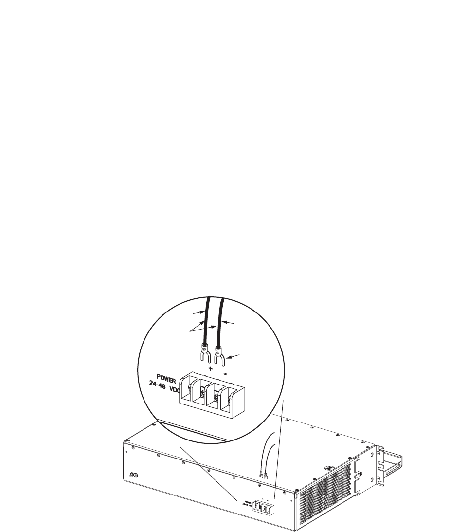
11 DC POWER CONNECTIONS
The HU is powered by ± 21 to ± 60 VDC power (nominal ± 24 or ± 48 VDC). The power is fed to
the HU through a screw-down type terminal strip located on the rear side of the unit. Power to
the HU must be supplied through a fuse panel such as the 20 position PowerWorx GMT Fuse
Panel (available separately) and the power must be protected with a 3 Amp GMT fuse. Use the
following procedure to install the power wiring:
1. Obtain one pair of #18 AWG (1.00 mm) red and black insulated copper wire for use as the
power wiring.
2. Terminate one end of each wire with a fork terminal as shown in Figure 3-15.
3. Connect the power wires to the power terminal strip at the rear of the HU.
Figure 3-15. DC Power Connections
4. Route the free ends of the wires to the fuse panel and locate the terminals that will be used
for the power feed. Refer to the user manual provided with the fuse panel for specific
information.
5. Remove the fuse from the circuit that will power the HU.
FORK
TERMINALS
#18 AWG
(1.0mm)
COPPER
WIRE
+ (RED)
– (BLACK)
16891-A

ADCP-75-158 • Preliminary Issue A • June 2003 • Section 3: Host Unit Installation
Page 3-17
© 2003, ADC Telecommunications, Inc.
6. Connect the power wires to the appropriate terminals as specified in the fuse panel user
manual.
7. Dress and secure the power wiring at the fuse panel and the HU. The procedure for
checking the voltage level and verifying that the HU is ready to power up is provided in
SECTION 4: OPERATION.

ADCP-75-158 • Preliminary Issue A • June 2003 • Section 3: Host Unit Installation
Page 3-18
© 2003, ADC Telecommunications, Inc.
Blank

ADCP-75-158 • Preliminary Issue A • June 2003 • Section 4: Operation
Page 4-1
© 2003, ADC Telecommunications, Inc.
SECTION 4: OPERATION
1 BEFORE STARTING OPERATION . . . . . . . . . . . . . . . . . . . . . . . . . . . . . . . . . . . . . . . . . . . . . . . . . . . . . . . . . . . .4-1
1.1 Tools and Materials . . . . . . . . . . . . . . . . . . . . . . . . . . . . . . . . . . . . . . . . . . . . . . . . . . . . . . . . . . . . . . .4-1
1.2 Readiness Check . . . . . . . . . . . . . . . . . . . . . . . . . . . . . . . . . . . . . . . . . . . . . . . . . . . . . . . . . . . . . . . . .4-2
2 TURN-UP SYSTEM AND VERIFY OPERATION . . . . . . . . . . . . . . . . . . . . . . . . . . . . . . . . . . . . . . . . . . . . . . . . . . . .4-2
2.1 Turn-Up Procedure. . . . . . . . . . . . . . . . . . . . . . . . . . . . . . . . . . . . . . . . . . . . . . . . . . . . . . . . . . . . . . . .4-3
2.2 Verify/Download HU and RU System Software . . . . . . . . . . . . . . . . . . . . . . . . . . . . . . . . . . . . . . . . . . . . .4-6
2.3 Determine Forward Path Input Signal Level . . . . . . . . . . . . . . . . . . . . . . . . . . . . . . . . . . . . . . . . . . . . . .4-7
2.4 Enter Site Name and Site Number . . . . . . . . . . . . . . . . . . . . . . . . . . . . . . . . . . . . . . . . . . . . . . . . . . . . 4-10
2.5 Enter Host Forward Attenuation . . . . . . . . . . . . . . . . . . . . . . . . . . . . . . . . . . . . . . . . . . . . . . . . . . . . . . 4-11
2.6 Determine Output Signal Level at STM Antenna Port . . . . . . . . . . . . . . . . . . . . . . . . . . . . . . . . . . . . . . . 4-12
2.7 Enter Remote Forward Attenuation. . . . . . . . . . . . . . . . . . . . . . . . . . . . . . . . . . . . . . . . . . . . . . . . . . . . 4-13
2.8 Enter Host Reverse Attenuation . . . . . . . . . . . . . . . . . . . . . . . . . . . . . . . . . . . . . . . . . . . . . . . . . . . . . . 4-15
2.9 Enter Host Forward and Reverse Delay . . . . . . . . . . . . . . . . . . . . . . . . . . . . . . . . . . . . . . . . . . . . . . . . . 4-17
_________________________________________________________________________________________________________
1 BEFORE STARTING OPERATION
This section provides guidelines for turning-up the Digivance system, verifying that all units are
operating properly, testing to ensure that all performance requirements are satisfied, and
correcting any installation problems. This process assumes that the various units have been
installed in accordance with the system design plan.
1.1 Tools and Materials
The following tools and materials are required in order to complete the procedures in this
section:
• Portable spectrum analyzer or RF power meter
• AC/DC voltmeter
• External attenuators (if specified in system design plan)
• PC-type computer with Digivance Element Management System (EMS) Version 2.0
software installed
• Straight-through RS-232 DB-9 interface cable (ADC part # 1192835)
• Handset
• Pencil or pen
• Writing pad
Content Page

ADCP-75-158 • Preliminary Issue A • June 2003 • Section 4: Operation
Page 4-2
© 2003, ADC Telecommunications, Inc.
1.2 Readiness Check
Before starting the turn-up process, inspect the complete Digivance system to verify that all
components of the system are ready to be powered-up. This will ensure that no units of the
system will be damaged during turn-up and that all existing systems will continue to function
properly.
1.2.1 Host Unit Installation Checks
Complete the following checks at the HU prior to starting the turn-up process:
1. Verify that the ON/OFF switch on the HU is in the OFF position (press O).
2. At the fuse panel, install a 3 Amp GMT fuse in the circuit that supplies DC power to the HU.
3. Using a DC voltmeter, verify that the DC voltage level at the HU power terminals is
between ± 21 to ± 60 VDC power (nominal ± 24 or ± 48 VDC). The DC power provided to
the HU can be either polarity.
4. Verify that all electrical and optical connections have been completed and that all optical
fibers, coaxial cables, and wires are properly routed and secured.
1.2.2 Remote Unit Installation Checks
Complete the following checks at the RU prior to starting the turn-up process:
1. Verify that the ON/OFF switch on the STM is in the OFF position (press O).
2. Verify that the MUTE/NORM/RESET switch on the LPA in the MUTE position.
3. At the AC breaker box, close the circuit breaker for the circuit that supplies AC power to
the RU.
4. Using an AC voltmeter, verify that the AC voltage level at the AC outlet is between 110
and 120 VAC (for 120 VAC powered systems) or between 220 and 240 VAC (for 240 VAC
powered systems).
5. Verify that all electrical and optical connections have been completed and that all optical
fibers, coaxial cables, and wires are properly routed and secured.
2 TURN-UP SYSTEM AND VERIFY OPERATION
The process of turning-up the system and verifying operation involves powering up the various
system components, verifying that the LED indicators show normal operation, setting the site
number and name, adjusting the RF signal levels, and adjusting the path delay.

ADCP-75-158 • Preliminary Issue A • June 2003 • Section 4: Operation
Page 4-3
© 2003, ADC Telecommunications, Inc.
2.1 Turn-Up Procedure
Each Digivance system should be turned-up separately before being networked together with
multiple systems through the CAN interface. Use the following procedure to turn-up each
Digivance system:
1. Temporarily disconnect the external alarm system or notify the alarm system provider that
testing is in progress.
2. If the HU is networked together with multiple HU’s, temporarily disconnect the CAN cables
from the NET IN and NET OUT ports of each HU.
3. Determine if the forward path composite input signal level at the Host Unit FORWARD RF IN
port is appropriate for the required RF output signal level and adjust by installing an external
attenuator if necessary. Refer to Section 2.3 for the calculation and adjustment procedure.
4. Connect the EMS computer (if not already connected) to the SERVICE connector on the
HU or STM front panel. If necessary, a separate laptop computer loaded with the EMS
Version 2.0 software can be temporarily connected and used to initially configure the
system.
5. Place the ON/OFF switch on the HU in the ON position (press I).
6. Make sure the switch on the LPA is in the MUTE position and then place the ON/OFF
switch on the STM in the ON position (press I).
7. Wait 6 to 8 seconds for the HU and the RU modules to initialize and then observe the LED
indicators on the HU, STM and LPA. Refer to Section 5 for the troubleshooting
procedures if the indicators do not respond as specified.
8. Start up the EMS Version 2.0 software program. The EMS main window will open as
shown in Figure 4-1. Note: The EMS software should be installed on a PC-type computer
and the PC’s COM port should be configured to interface with the HU. For information
about installing the EMS software and configuring the PC’s COM port, refer to the
Digivance Element Management System Software User Manual (ADCP-75-125).
Note: By default, all HU’s and RU’s are programmed with the same site number and
name. This can cause problems for the EMS if multiple HU’s with the same site number
and site name are networked together through the CAN interface. It is therefore necessary
to temporarily disconnect the CAN interface cables from the HU when configuring the
system for operation until a unique site number and name can be assigned.
HOST UNIT SPECTRUM TRANSPORT MODULE LINEAR POWER AMPLIFIER
POWER – Green AC POWER – Green STATUS – Steady green
STANDBY – Off STANDBY – Off
HOST UNIT – Green HOST UNIT – Green
REMOTE UNIT – Green STM – Green
DRIVE – Green, Yellow, or Red PA – Green
PORT 1/PORT 2 – Green VSWR – Green
PORT 1/PORT 2 – Green