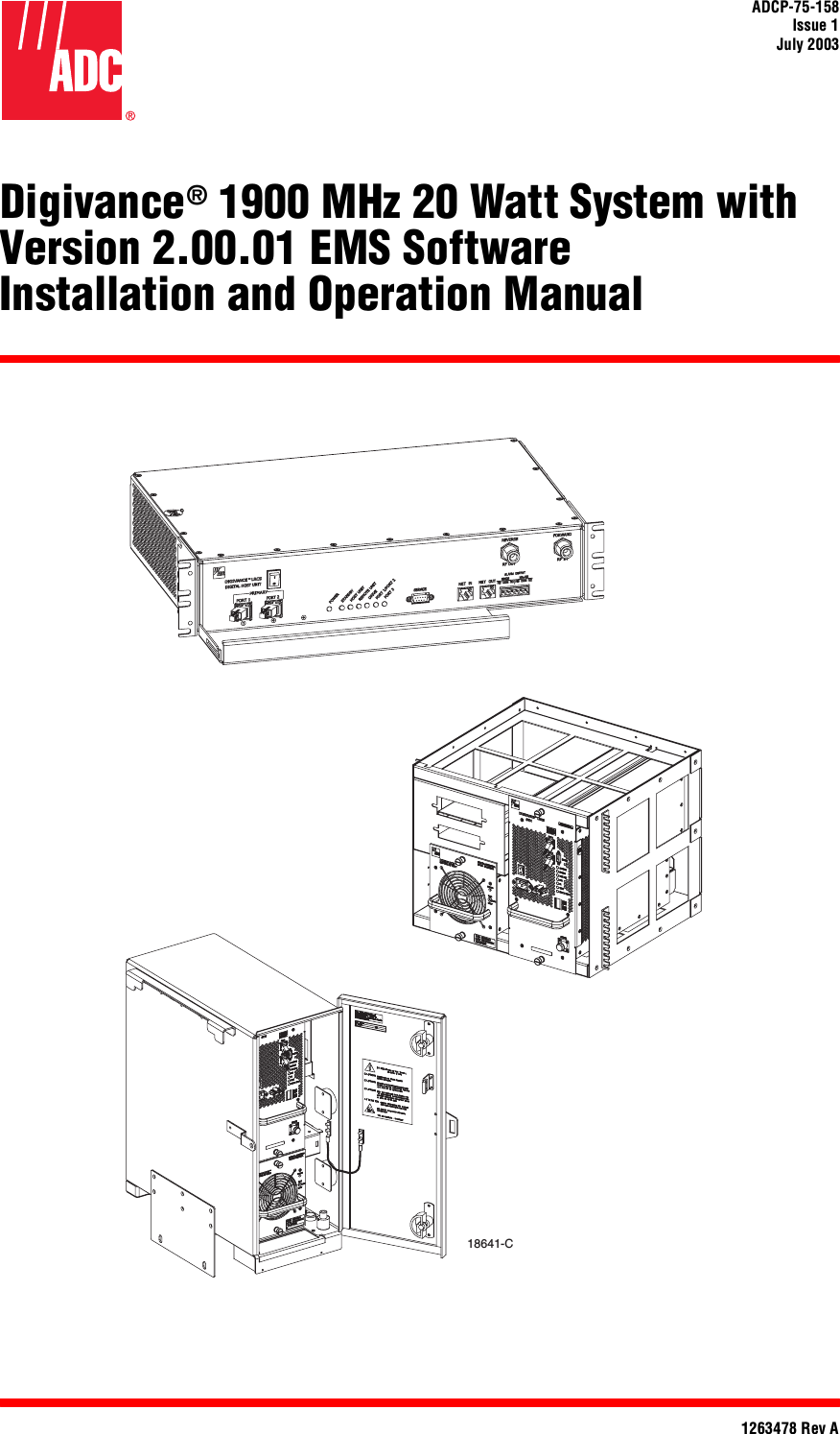
ADC Telecommunications DLC1902B Digivance® LRCS 1900 MHz, 20-Watt LPA User Manual 75158

ADC Telecommunications Inc Digivance® LRCS 1900 MHz, 20-Watt LPA 75158

User manual 1

ADCP-75-158Issue 1July 20031263478 Rev ADigivance® 1900 MHz 20 Watt System withVersion 2.00.01 EMS SoftwareInstallation and Operation Manual18641-C
ADCP-75-158Issue 1July 20031263478 Rev ADigivance® 1900 MHz 20 Watt System withVersion 2.00.01 EMS SoftwareInstallation and Operation Manual
ADCP-75-158 • Issue 1 • July 2003 • PrefacePage iiCOPYRIGHT© 2003, ADC Telecommunications, Inc.All Rights ReservedPrinted in the U.S.A.REVISION HISTORYTRADEMARK INFORMATIONADC, Digivance, and PowerWorx are registered trademarks of ADC Telecommunications, Inc.Procomm Plus is a registered trademark of Quarterdeck Corporation. DISCLAIMER OF LIABILITYContents herein are current as of the date of publication. ADC reserves the right to change the contents without prior notice. In noevent shall ADC be liable for any damages resulting from loss of data, loss of use, or loss of profits and ADC furtherdisclaims any and all liability for indirect, incidental, special, consequential or other similar damages. This disclaimer ofliability applies to all products, publications and services during and after the warranty period.This publication may be verified at any time by contacting ADC’s Technical Assistance Center at 1-800-366-3891, extension 73475(in U.S.A. or Canada) or 952-917-3475 (outside U.S.A. and Canada), or by e-mail to connectivity_tac@adc.comISSUE DATE REASON FOR CHANGE1 07/2003 Original issue.ADC Telecommunications, Inc.P.O. Box 1101, Minneapolis, Minnesota 55440-1101In U.S.A. and Canada: 1-800-366-3891Outside U.S.A. and Canada: (952) 938-8080Fax: (952) 917-1717
ADCP-75-158 • Issue 1 • July 2003 • PrefacePage iii© 2003, ADC Telecommunications, Inc.TABLE OF CONTENTSContent PageABOUT THIS MANUAL  . . . . . . . . . . . . . . . . . . . . . . . . . . . . . . . . . . . . . . . . . . . . . . . . . . . . . . . . . . . . . . . . . . . . . . . .  viiRELATED PUBLICATIONS  . . . . . . . . . . . . . . . . . . . . . . . . . . . . . . . . . . . . . . . . . . . . . . . . . . . . . . . . . . . . . . . . . . . . . .  viiADMONISHMENTS   . . . . . . . . . . . . . . . . . . . . . . . . . . . . . . . . . . . . . . . . . . . . . . . . . . . . . . . . . . . . . . . . . . . . . . . . . . viiiGENERAL SAFETY PRECAUTIONS  . . . . . . . . . . . . . . . . . . . . . . . . . . . . . . . . . . . . . . . . . . . . . . . . . . . . . . . . . . . . . . . . viiiSTANDARDS CERTIFICATION   . . . . . . . . . . . . . . . . . . . . . . . . . . . . . . . . . . . . . . . . . . . . . . . . . . . . . . . . . . . . . . . . . . . . ixLIST OF ACRONYMS AND ABBREVIATIONS . . . . . . . . . . . . . . . . . . . . . . . . . . . . . . . . . . . . . . . . . . . . . . . . . . . . . . . . . . . ixSECTION 1:OVERVIEW1 INTRODUCTION. . . . . . . . . . . . . . . . . . . . . . . . . . . . . . . . . . . . . . . . . . . . . . . . . . . . . . . . . . . . . . . . . . . . . . . .1-12  1900 MHZ 20 WATT SYSTEM OVERVIEW . . . . . . . . . . . . . . . . . . . . . . . . . . . . . . . . . . . . . . . . . . . . . . . . . . . . . .1-12.1 Basic System Components  . . . . . . . . . . . . . . . . . . . . . . . . . . . . . . . . . . . . . . . . . . . . . . . . . . . . . . . . . .1-12.2 Base Transceiver Station to Host Unit Interface . . . . . . . . . . . . . . . . . . . . . . . . . . . . . . . . . . . . . . . . . . . .1-32.3  Handset Interface . . . . . . . . . . . . . . . . . . . . . . . . . . . . . . . . . . . . . . . . . . . . . . . . . . . . . . . . . . . . . . . .1-42.4 Local Service Interface. . . . . . . . . . . . . . . . . . . . . . . . . . . . . . . . . . . . . . . . . . . . . . . . . . . . . . . . . . . . .1-42.5 Remote NOC Interface  . . . . . . . . . . . . . . . . . . . . . . . . . . . . . . . . . . . . . . . . . . . . . . . . . . . . . . . . . . . . .1-53 SYSTEM FUNCTIONS AND FEATURES  . . . . . . . . . . . . . . . . . . . . . . . . . . . . . . . . . . . . . . . . . . . . . . . . . . . . . . . .1-63.1 Fiber Optic Transport . . . . . . . . . . . . . . . . . . . . . . . . . . . . . . . . . . . . . . . . . . . . . . . . . . . . . . . . . . . . . .1-63.2 Control and Monitoring Software . . . . . . . . . . . . . . . . . . . . . . . . . . . . . . . . . . . . . . . . . . . . . . . . . . . . . .1-93.3 Fault Detection and Alarm Reporting . . . . . . . . . . . . . . . . . . . . . . . . . . . . . . . . . . . . . . . . . . . . . . . . . . .1-93.4 Powering . . . . . . . . . . . . . . . . . . . . . . . . . . . . . . . . . . . . . . . . . . . . . . . . . . . . . . . . . . . . . . . . . . . . . .1-93.5 Equipment Mounting and Configuration  . . . . . . . . . . . . . . . . . . . . . . . . . . . . . . . . . . . . . . . . . . . . . . . . .1-9SECTION 2:DESCRIPTION1 INTRODUCTION. . . . . . . . . . . . . . . . . . . . . . . . . . . . . . . . . . . . . . . . . . . . . . . . . . . . . . . . . . . . . . . . . . . . . . . .2-32 HOST UNIT . . . . . . . . . . . . . . . . . . . . . . . . . . . . . . . . . . . . . . . . . . . . . . . . . . . . . . . . . . . . . . . . . . . . . . . . . . .2-32.1 Primary Components . . . . . . . . . . . . . . . . . . . . . . . . . . . . . . . . . . . . . . . . . . . . . . . . . . . . . . . . . . . . . .2-32.2 Mounting . . . . . . . . . . . . . . . . . . . . . . . . . . . . . . . . . . . . . . . . . . . . . . . . . . . . . . . . . . . . . . . . . . . . . .2-32.3 Fault Detection and Alarm Reporting . . . . . . . . . . . . . . . . . . . . . . . . . . . . . . . . . . . . . . . . . . . . . . . . . . .2-42.4 RF Signal Connections . . . . . . . . . . . . . . . . . . . . . . . . . . . . . . . . . . . . . . . . . . . . . . . . . . . . . . . . . . . . .2-42.5 RF Signal Level Adjustments. . . . . . . . . . . . . . . . . . . . . . . . . . . . . . . . . . . . . . . . . . . . . . . . . . . . . . . . .2-42.6 Propagation Delay . . . . . . . . . . . . . . . . . . . . . . . . . . . . . . . . . . . . . . . . . . . . . . . . . . . . . . . . . . . . . . . .2-52.7 Optical Connection  . . . . . . . . . . . . . . . . . . . . . . . . . . . . . . . . . . . . . . . . . . . . . . . . . . . . . . . . . . . . . . .2-52.8 Controller Area Network Interface Connection . . . . . . . . . . . . . . . . . . . . . . . . . . . . . . . . . . . . . . . . . . . . .2-52.9 Service Interface Connection. . . . . . . . . . . . . . . . . . . . . . . . . . . . . . . . . . . . . . . . . . . . . . . . . . . . . . . . .2-52.10 Powering . . . . . . . . . . . . . . . . . . . . . . . . . . . . . . . . . . . . . . . . . . . . . . . . . . . . . . . . . . . . . . . . . . . . . .2-52.11 Cooling  . . . . . . . . . . . . . . . . . . . . . . . . . . . . . . . . . . . . . . . . . . . . . . . . . . . . . . . . . . . . . . . . . . . . . . .2-62.12 User Interface . . . . . . . . . . . . . . . . . . . . . . . . . . . . . . . . . . . . . . . . . . . . . . . . . . . . . . . . . . . . . . . . . . . 2-63 REMOTE UNIT OUTDOOR CABINET  . . . . . . . . . . . . . . . . . . . . . . . . . . . . . . . . . . . . . . . . . . . . . . . . . . . . . . . . . .2-7
ADCP-75-158 • Issue 1 • July 2003 • PrefacePage iv© 2003, ADC Telecommunications, Inc.TABLE OF CONTENTSContent Page3.1 Primary Components . . . . . . . . . . . . . . . . . . . . . . . . . . . . . . . . . . . . . . . . . . . . . . . . . . . . . . . . . . . . . . 2-83.2 Mounting . . . . . . . . . . . . . . . . . . . . . . . . . . . . . . . . . . . . . . . . . . . . . . . . . . . . . . . . . . . . . . . . . . . . . . 2-93.3 STM and LPA Module Installation  . . . . . . . . . . . . . . . . . . . . . . . . . . . . . . . . . . . . . . . . . . . . . . . . . . . . . 2-93.4 WDM and CWDM Installation . . . . . . . . . . . . . . . . . . . . . . . . . . . . . . . . . . . . . . . . . . . . . . . . . . . . . . . . 2-93.5 Fiber Optic Cable Entry  . . . . . . . . . . . . . . . . . . . . . . . . . . . . . . . . . . . . . . . . . . . . . . . . . . . . . . . . . . . . 2-93.6 Antenna Cable Connection . . . . . . . . . . . . . . . . . . . . . . . . . . . . . . . . . . . . . . . . . . . . . . . . . . . . . . . . . 2-103.7 AC Power Wiring and Grounding . . . . . . . . . . . . . . . . . . . . . . . . . . . . . . . . . . . . . . . . . . . . . . . . . . . . . 2-103.8 Ventilation . . . . . . . . . . . . . . . . . . . . . . . . . . . . . . . . . . . . . . . . . . . . . . . . . . . . . . . . . . . . . . . . . . . . 2-103.9 User Interface. . . . . . . . . . . . . . . . . . . . . . . . . . . . . . . . . . . . . . . . . . . . . . . . . . . . . . . . . . . . . . . . . . 2-104 REMOTE UNIT INDOOR MOUNTING SHELF . . . . . . . . . . . . . . . . . . . . . . . . . . . . . . . . . . . . . . . . . . . . . . . . . . . . 2-124.1 Primary Components . . . . . . . . . . . . . . . . . . . . . . . . . . . . . . . . . . . . . . . . . . . . . . . . . . . . . . . . . . . . . 2-124.2 STM and LPA Module Installation  . . . . . . . . . . . . . . . . . . . . . . . . . . . . . . . . . . . . . . . . . . . . . . . . . . . . 2-134.3 WDM and CWDM Installation . . . . . . . . . . . . . . . . . . . . . . . . . . . . . . . . . . . . . . . . . . . . . . . . . . . . . . . 2-134.4 Fiber Optic Cable Installation . . . . . . . . . . . . . . . . . . . . . . . . . . . . . . . . . . . . . . . . . . . . . . . . . . . . . . . 2-134.5 Antenna Cable Connections  . . . . . . . . . . . . . . . . . . . . . . . . . . . . . . . . . . . . . . . . . . . . . . . . . . . . . . . . 2-144.6 AC Power Wiring and Grounding . . . . . . . . . . . . . . . . . . . . . . . . . . . . . . . . . . . . . . . . . . . . . . . . . . . . . 2-144.7 User Interface. . . . . . . . . . . . . . . . . . . . . . . . . . . . . . . . . . . . . . . . . . . . . . . . . . . . . . . . . . . . . . . . . . 2-145 SPECTRUM TRANSPORT MODULE  . . . . . . . . . . . . . . . . . . . . . . . . . . . . . . . . . . . . . . . . . . . . . . . . . . . . . . . . . 2-155.1 Primary Components . . . . . . . . . . . . . . . . . . . . . . . . . . . . . . . . . . . . . . . . . . . . . . . . . . . . . . . . . . . . . 2-155.2 Mounting . . . . . . . . . . . . . . . . . . . . . . . . . . . . . . . . . . . . . . . . . . . . . . . . . . . . . . . . . . . . . . . . . . . . . 2-165.3 Fault Detection and Alarm Reporting . . . . . . . . . . . . . . . . . . . . . . . . . . . . . . . . . . . . . . . . . . . . . . . . . . 2-165.4 Antenna Cable Connection . . . . . . . . . . . . . . . . . . . . . . . . . . . . . . . . . . . . . . . . . . . . . . . . . . . . . . . . . 2-165.5 RF Signal Level Adjustment . . . . . . . . . . . . . . . . . . . . . . . . . . . . . . . . . . . . . . . . . . . . . . . . . . . . . . . . 2-175.6 Optical Connection  . . . . . . . . . . . . . . . . . . . . . . . . . . . . . . . . . . . . . . . . . . . . . . . . . . . . . . . . . . . . . . 2-175.7 Service Interface Connection  . . . . . . . . . . . . . . . . . . . . . . . . . . . . . . . . . . . . . . . . . . . . . . . . . . . . . . . 2-175.8 Powering . . . . . . . . . . . . . . . . . . . . . . . . . . . . . . . . . . . . . . . . . . . . . . . . . . . . . . . . . . . . . . . . . . . . . 2-175.9 Cooling . . . . . . . . . . . . . . . . . . . . . . . . . . . . . . . . . . . . . . . . . . . . . . . . . . . . . . . . . . . . . . . . . . . . . . 2-175.10 User Interface. . . . . . . . . . . . . . . . . . . . . . . . . . . . . . . . . . . . . . . . . . . . . . . . . . . . . . . . . . . . . . . . . . 2-176 LINEAR POWER AMPLIFIER . . . . . . . . . . . . . . . . . . . . . . . . . . . . . . . . . . . . . . . . . . . . . . . . . . . . . . . . . . . . . . 2-196.1 Primary Components . . . . . . . . . . . . . . . . . . . . . . . . . . . . . . . . . . . . . . . . . . . . . . . . . . . . . . . . . . . . . 2-196.2 Mounting . . . . . . . . . . . . . . . . . . . . . . . . . . . . . . . . . . . . . . . . . . . . . . . . . . . . . . . . . . . . . . . . . . . . . 2-206.3 Fault Detection and Alarm Reporting . . . . . . . . . . . . . . . . . . . . . . . . . . . . . . . . . . . . . . . . . . . . . . . . . . 2-206.4 Powering . . . . . . . . . . . . . . . . . . . . . . . . . . . . . . . . . . . . . . . . . . . . . . . . . . . . . . . . . . . . . . . . . . . . . 2-206.5 Cooling . . . . . . . . . . . . . . . . . . . . . . . . . . . . . . . . . . . . . . . . . . . . . . . . . . . . . . . . . . . . . . . . . . . . . . 2-216.6 User Interface. . . . . . . . . . . . . . . . . . . . . . . . . . . . . . . . . . . . . . . . . . . . . . . . . . . . . . . . . . . . . . . . . . 2-217 INTERFACE PANELS (ACCESSORY) . . . . . . . . . . . . . . . . . . . . . . . . . . . . . . . . . . . . . . . . . . . . . . . . . . . . . . . . . 2-228 WAVELENGTH DIVISION MULTIPLEXER SYSTEM (ACCESSORY)  . . . . . . . . . . . . . . . . . . . . . . . . . . . . . . . . . . . . . 2-239 COARSE WAVELENGTH DIVISION MULTIPLEXER SYSTEM (ACCESSORY) . . . . . . . . . . . . . . . . . . . . . . . . . . . . . . . 2-2410 DIGIVANCE ELEMENT MANAGEMENT SYSTEM  . . . . . . . . . . . . . . . . . . . . . . . . . . . . . . . . . . . . . . . . . . . . . . . . . 2-2510.1 Primary Components . . . . . . . . . . . . . . . . . . . . . . . . . . . . . . . . . . . . . . . . . . . . . . . . . . . . . . . . . . . . . 2-2510.2 Service Interface Connection  . . . . . . . . . . . . . . . . . . . . . . . . . . . . . . . . . . . . . . . . . . . . . . . . . . . . . . . 2-26
ADCP-75-158 • Issue 1 • July 2003 • PrefacePage v© 2003, ADC Telecommunications, Inc.TABLE OF CONTENTSContent Page10.3 NOC Interface Connection . . . . . . . . . . . . . . . . . . . . . . . . . . . . . . . . . . . . . . . . . . . . . . . . . . . . . . . . . . 2-2610.4 EMS Software User Interface. . . . . . . . . . . . . . . . . . . . . . . . . . . . . . . . . . . . . . . . . . . . . . . . . . . . . . . . 2-2611 SPECIFICATIONS. . . . . . . . . . . . . . . . . . . . . . . . . . . . . . . . . . . . . . . . . . . . . . . . . . . . . . . . . . . . . . . . . . . . . . 2-27SECTION 3:HOST UNIT INSTALLATION1 BEFORE STARTING INSTALLATION  . . . . . . . . . . . . . . . . . . . . . . . . . . . . . . . . . . . . . . . . . . . . . . . . . . . . . . . . . .3-11.1 Tools and Materials . . . . . . . . . . . . . . . . . . . . . . . . . . . . . . . . . . . . . . . . . . . . . . . . . . . . . . . . . . . . . . .3-11.2 Unpacking and Inspection. . . . . . . . . . . . . . . . . . . . . . . . . . . . . . . . . . . . . . . . . . . . . . . . . . . . . . . . . . .3-22 FIBER OPTIC CABLE ROUTING AND INSTALLATION GUIDELINES  . . . . . . . . . . . . . . . . . . . . . . . . . . . . . . . . . . . . . .3-23 WDM MOUNTING PROCEDURE (OPTIONAL ACCESSORY) . . . . . . . . . . . . . . . . . . . . . . . . . . . . . . . . . . . . . . . . . . .3-44 HU MOUNTING PROCEDURE . . . . . . . . . . . . . . . . . . . . . . . . . . . . . . . . . . . . . . . . . . . . . . . . . . . . . . . . . . . . . . .3-65 CHASSIS GROUND CONNECTION. . . . . . . . . . . . . . . . . . . . . . . . . . . . . . . . . . . . . . . . . . . . . . . . . . . . . . . . . . . .3-86 COAXIAL CABLE CONNECTIONS. . . . . . . . . . . . . . . . . . . . . . . . . . . . . . . . . . . . . . . . . . . . . . . . . . . . . . . . . . . . .3-87 OPTICAL CONNECTIONS. . . . . . . . . . . . . . . . . . . . . . . . . . . . . . . . . . . . . . . . . . . . . . . . . . . . . . . . . . . . . . . . . 3-107.1 Optical Connections Without WDM or CWDM system  . . . . . . . . . . . . . . . . . . . . . . . . . . . . . . . . . . . . . . . 3-107.2 Optical Connections With WDM System  . . . . . . . . . . . . . . . . . . . . . . . . . . . . . . . . . . . . . . . . . . . . . . . . 3-118 CONTROLLER AREA NETWORK CONNECTIONS  . . . . . . . . . . . . . . . . . . . . . . . . . . . . . . . . . . . . . . . . . . . . . . . . . 3-139 EMS COMPUTER CONNECTION . . . . . . . . . . . . . . . . . . . . . . . . . . . . . . . . . . . . . . . . . . . . . . . . . . . . . . . . . . . . 3-1410 EXTERNAL ALARM SYSTEM CONNECTIONS  . . . . . . . . . . . . . . . . . . . . . . . . . . . . . . . . . . . . . . . . . . . . . . . . . . . 3-1511 DC POWER CONNECTIONS . . . . . . . . . . . . . . . . . . . . . . . . . . . . . . . . . . . . . . . . . . . . . . . . . . . . . . . . . . . . . . . 3-16SECTION 4:OPERATION1 BEFORE STARTING OPERATION  . . . . . . . . . . . . . . . . . . . . . . . . . . . . . . . . . . . . . . . . . . . . . . . . . . . . . . . . . . . .4-11.1 Tools and Materials . . . . . . . . . . . . . . . . . . . . . . . . . . . . . . . . . . . . . . . . . . . . . . . . . . . . . . . . . . . . . . .4-11.2 Readiness Check . . . . . . . . . . . . . . . . . . . . . . . . . . . . . . . . . . . . . . . . . . . . . . . . . . . . . . . . . . . . . . . . .4-22 TURN-UP SYSTEM AND VERIFY OPERATION . . . . . . . . . . . . . . . . . . . . . . . . . . . . . . . . . . . . . . . . . . . . . . . . . . . .4-22.1 Turn-Up Procedure. . . . . . . . . . . . . . . . . . . . . . . . . . . . . . . . . . . . . . . . . . . . . . . . . . . . . . . . . . . . . . . .4-32.2 Verify/Download HU and RU System Software . . . . . . . . . . . . . . . . . . . . . . . . . . . . . . . . . . . . . . . . . . . . .4-62.3 Determine Forward Path Input Signal Level  . . . . . . . . . . . . . . . . . . . . . . . . . . . . . . . . . . . . . . . . . . . . . .4-72.4 Enter Site Name and Site Number  . . . . . . . . . . . . . . . . . . . . . . . . . . . . . . . . . . . . . . . . . . . . . . . . . . . . 4-102.5 Enter Host Forward Attenuation . . . . . . . . . . . . . . . . . . . . . . . . . . . . . . . . . . . . . . . . . . . . . . . . . . . . . . 4-112.6 Determine Output Signal Level at STM Antenna Port  . . . . . . . . . . . . . . . . . . . . . . . . . . . . . . . . . . . . . . . 4-122.7 Enter Remote Forward Attenuation. . . . . . . . . . . . . . . . . . . . . . . . . . . . . . . . . . . . . . . . . . . . . . . . . . . . 4-132.8 Enter Host Reverse Attenuation . . . . . . . . . . . . . . . . . . . . . . . . . . . . . . . . . . . . . . . . . . . . . . . . . . . . . . 4-152.9 Enter Host Forward and Reverse Delay . . . . . . . . . . . . . . . . . . . . . . . . . . . . . . . . . . . . . . . . . . . . . . . . . 4-17
ADCP-75-158 • Issue 1 • July 2003 • PrefacePage vi© 2003, ADC Telecommunications, Inc.TABLE OF CONTENTSContent PageSECTION 5:MAINTENANCE1 SYSTEM MAINTENANCE OVERVIEW  . . . . . . . . . . . . . . . . . . . . . . . . . . . . . . . . . . . . . . . . . . . . . . . . . . . . . . . . . 5-11.1 Tools and Materials. . . . . . . . . . . . . . . . . . . . . . . . . . . . . . . . . . . . . . . . . . . . . . . . . . . . . . . . . . . . . . . 5-12 FAULT DETECTION AND ALARM REPORTING  . . . . . . . . . . . . . . . . . . . . . . . . . . . . . . . . . . . . . . . . . . . . . . . . . . . 5-23 FAULT ISOLATION AND TROUBLESHOOTING  . . . . . . . . . . . . . . . . . . . . . . . . . . . . . . . . . . . . . . . . . . . . . . . . . . . 5-53.1 Host Unit Troubleshooting  . . . . . . . . . . . . . . . . . . . . . . . . . . . . . . . . . . . . . . . . . . . . . . . . . . . . . . . . . . 5-63.2 STM Troubleshooting. . . . . . . . . . . . . . . . . . . . . . . . . . . . . . . . . . . . . . . . . . . . . . . . . . . . . . . . . . . . . . 5-83.3 LPA Troubleshooting . . . . . . . . . . . . . . . . . . . . . . . . . . . . . . . . . . . . . . . . . . . . . . . . . . . . . . . . . . . . . 5-104 TEST PROCEDURES  . . . . . . . . . . . . . . . . . . . . . . . . . . . . . . . . . . . . . . . . . . . . . . . . . . . . . . . . . . . . . . . . . . . 5-114.1 Optical Power Test  . . . . . . . . . . . . . . . . . . . . . . . . . . . . . . . . . . . . . . . . . . . . . . . . . . . . . . . . . . . . . . 5-114.2 Optical Loopback Test . . . . . . . . . . . . . . . . . . . . . . . . . . . . . . . . . . . . . . . . . . . . . . . . . . . . . . . . . . . . 5-125 MAINTENANCE PROCEDURES. . . . . . . . . . . . . . . . . . . . . . . . . . . . . . . . . . . . . . . . . . . . . . . . . . . . . . . . . . . . . 5-145.1 Scheduled Maintenance. . . . . . . . . . . . . . . . . . . . . . . . . . . . . . . . . . . . . . . . . . . . . . . . . . . . . . . . . . . 5-145.2 Remote Unit Outdoor Cabinet Filter Cleaning Procedure. . . . . . . . . . . . . . . . . . . . . . . . . . . . . . . . . . . . . 5-145.3 Host Unit Fan Replacement Procedure . . . . . . . . . . . . . . . . . . . . . . . . . . . . . . . . . . . . . . . . . . . . . . . . . 5-155.4 Spectrum Transport Module Fan Replacement Procedure . . . . . . . . . . . . . . . . . . . . . . . . . . . . . . . . . . . . 5-175.5 Linear Power Amplifier Fan Replacement Procedure . . . . . . . . . . . . . . . . . . . . . . . . . . . . . . . . . . . . . . . 5-19SECTION 6:GENERAL INFORMATION1 WARRANTY/SOFTWARE  . . . . . . . . . . . . . . . . . . . . . . . . . . . . . . . . . . . . . . . . . . . . . . . . . . . . . . . . . . . . . . . . . 6-12 SOFTWARE SERVICE AGREEMENT  . . . . . . . . . . . . . . . . . . . . . . . . . . . . . . . . . . . . . . . . . . . . . . . . . . . . . . . . . . 6-13 REPAIR/EXCHANGE POLICY . . . . . . . . . . . . . . . . . . . . . . . . . . . . . . . . . . . . . . . . . . . . . . . . . . . . . . . . . . . . . . . 6-14 REPAIR CHARGES. . . . . . . . . . . . . . . . . . . . . . . . . . . . . . . . . . . . . . . . . . . . . . . . . . . . . . . . . . . . . . . . . . . . . . 6-25 REPLACEMENT/SPARE PRODUCTS . . . . . . . . . . . . . . . . . . . . . . . . . . . . . . . . . . . . . . . . . . . . . . . . . . . . . . . . . . 6-26 RETURNED MATERIAL. . . . . . . . . . . . . . . . . . . . . . . . . . . . . . . . . . . . . . . . . . . . . . . . . . . . . . . . . . . . . . . . . . . 6-27 CUSTOMER INFORMATION AND ASSISTANCE. . . . . . . . . . . . . . . . . . . . . . . . . . . . . . . . . . . . . . . . . . . . . . . . . . . 6-3
ADCP-75-158 • Issue 1 • July 2003 • PrefacePage vii© 2003, ADC Telecommunications, Inc.ABOUT THIS MANUALThis installation and operation manual provides the following information:• An overview of the Digivance 1900 MHz 20 Watt System. • A description of the basic system components including the Host Unit (HU), SpectrumTransport Module (STM), Linear Power Amplifier (LPA), Remote Unit (RU) outdoorcabinet, RU indoor mounting shelf, and Digivance Element Management System (EMS). • Installation procedures for the HU. • Procedures for tuning-up the system and verifying that the system is functioning properly.• Procedures for maintaining the system including troubleshooting problems and replacingfaulty components. • Product warranty, repair, return, and replacement information. The procedures for installing the remote unit and for installing and using the EMS software areprovided in other publications which are referenced in the Related Publications section and atappropriate points within this manual. RELATED PUBLICATIONSListed below are all the related manuals, their content, and their publication numbers. Copies ofthese publications can be ordered by contacting the Technical Assistance Center at1-800-366-3891,extension 73475 (in U.S.A. or Canada) or 952-917-3475 (outside U.S.A. andCanada).Digivance 20 Watt Indoor Remote Unit Installation Instructions 75-149Provides instructions for installing the STM, LPA, and accessories in the indoorremote unit mounting shelf and for installing and connecting the fiber optic,coaxial, and AC power cables. Digivance 20 Watt Outdoor Remote Unit Installation Instructions 75-148Provides instructions for installing the STM, LPA, and accessories in theoutdoor remote unit cabinet and for installing and connecting the fiber optic,coaxial, and AC power cables. Digivance 20 Watt Remote Unit Cabinet Mounting Instructions 75-147Provides instructions for locating and mounting the remote unit cabinet. Digivance Element Management System Version 2.0 User Manual 75-125Provides instructions for installing the Digivance Element Management Systemsoftware and for using both the Graphical User Interface (GUI) and theNetwork Operations Center (NOC) versions of the software. Title/Description ADCP Number
ADCP-75-158 • Issue 1 • July 2003 • PrefacePage viii© 2003, ADC Telecommunications, Inc.Digivance RF Transport Solution 800 and 1900 MHz InterfacePanels User Manual 75-144Describes the 800 and 1900 MHz Conditioning Panel and Duplexing Panel andprovides procedures for configuration and installation. Digivance System Coarse Wavelength Division Multiplexer User Manual 75-142Describes the Coarse Wavelength Division Multiplexer and providesprocedures for configuration and installation. ADMONISHMENTSImportant safety admonishments are used throughout this manual to warn of possible hazards topersons or equipment. An admonishment identifies a possible hazard and then explains whatmay happen if the hazard is not avoided. The admonishments — in the form of Dangers,Warnings, and Cautions — must be followed at all times. These warnings are flagged by use ofthe triangular alert icon (seen below), and are listed in descending order of severity of injury ordamage and likelihood of occurrence.GENERAL SAFETY PRECAUTIONSDanger: Danger is used to indicate the presence of a hazard that will cause severe personalinjury, death, or substantial property damage if the hazard is not avoided.Warning: Warning is used to indicate the presence of a hazard that can cause severe personalinjury, death, or substantial property damage if the hazard is not avoided.Caution: Caution is used to indicate the presence of a hazard that will or can cause minorpersonal injury or property damage if the hazard is not avoided.Danger: This equipment uses a Class 1 Laser according to FDA/CDRH rules. Laser radiationcan seriously damage the retina of the eye. Do not look into the ends of any optical fiber. Do notlook directly into the optical transceiver of any digital unit or exposure to laser radiation mayresult. An optical power meter should be used to verify active fibers. A protective cap or hoodMUST be immediately placed over any radiating transceiver or optical fiber connector to avoidthe potential of dangerous amounts of radiation exposure. This practice also prevents dirtparticles from entering the adapter or connector. Danger: Do not look into the ends of any optical fiber. Exposure to laser radiation may result.Do not assume laser power is turned-off or the fiber is disconnected at the other end. Danger: Wet conditions increase the potential for receiving an electrical shock when installingor using electrically-powered equipment. To prevent electrical shock, never install or useelectrical equipment in a wet location or during a lightning storm.
ADCP-75-158 • Issue 1 • July 2003 • PrefacePage ix© 2003, ADC Telecommunications, Inc.STANDARDS CERTIFICATIONFCC: This equipment complies with the applicable sections of Title 47 CFR Part 24. UL/CUL: This equipment complies with UL and CUL 50 Standard for Enclosures forElectrical Equipment. This equipment provides the degree of protection specified by IP43 asdefined in IEC Publication 529. FDA/CDRH: This equipment uses a Class 1 LASER according to FDA/CDRH Rules. Thisproduct conforms to all applicable standards of 21 CFR Part 1040. IC: This equipment complies with the applicable sections of RSS-131. The term “IC:” before theradio certification number only signifies that Industry Canada Technical Specifications were met.LIST OF ACRONYMS AND ABBREVIATIONSThe acronyms and abbreviations used in this manual are detailed in the following list:AC Alternating CurrentASCII American Standard Code for Information InterchangeAtt AttenuationAWG American Wire GaugeBER Bit Error RateBTS Base Transceiver StationCCentigradeCAN Controller Area NetworkCDRH Center for Devices and Radiological HealthCD-ROM Compact Disk Read Only MemoryCOM CommonConfig ConfigurationCUL Canadian Underwriters LaboratoriesCWDM Coarse Wavelength Division MultiplexerDC Direct CurrentDCE Data Communications EquipmentDTE Data Terminal EquipmentEIA Electronic Industries AssociationWarning:  The HU is powered by 48 VDC power which is supplied over customer-providedwiring. To prevent electrical shock when installing or modifying the HU power wiring,disconnect the wiring at the power source before working with uninsulated wires or terminals. Caution: Always allow sufficient fiber length to permit routing of patch cords and pigtailswithout severe bends. Fiber optic patch cords or pigtails may be permanently damaged if bentor curved to a radius of less than 2 inches (50 mm).
ADCP-75-158 • Issue 1 • July 2003 • PrefacePage x© 2003, ADC Telecommunications, Inc.EMS Element Management SystemESD Electrostatic DischargeFFahrenheitFCC Federal Communications CommissionFDA Food and Drug AdministrationFSO Free Space OpticsFwd ForwardGFCI Ground Fault Circuit InterruptingGUI Graphical User InterfaceHU Host UnitIC Industry CanadaLED Light Emitting DiodeLPA Linear Power AmplifierMHz Mega HertzMPE Maximum Permissible ExposureMTBF Mean Time Between FailureNC Normally ClosedNEM Network Element ManagerNO Normally OpenNOC Network Operations CenterNPT National Pipe TaperedOSP Outside PlantPA Power AmplifierPC Personal ComputerPCS Personal Communications SystemPrg ProgramPwr PowerRev ReverseRF Radio FrequencyRMA Return Material AuthorizationRU Remote UnitRX Receive or ReceiverSTM Spectrum Transport ModuleTX Transmit or TransmitterUL Underwriters LaboratoriesVAC Volts Alternating CurrentVDC Volts Direct CurrentVSWR Voltage Standing Wave RatioWECO Western Electric CompanyWDM Wave Division Multiplexer
ADCP-75-158 • Issue 1 • July 2003 • Section 1: OverviewPage 1-1© 2003, ADC Telecommunications, Inc.SECTION 1: OVERVIEW1 INTRODUCTION. . . . . . . . . . . . . . . . . . . . . . . . . . . . . . . . . . . . . . . . . . . . . . . . . . . . . . . . . . . . . . . . . . . . . . . .1-12  1900 MHZ 20 WATT SYSTEM OVERVIEW . . . . . . . . . . . . . . . . . . . . . . . . . . . . . . . . . . . . . . . . . . . . . . . . . . . . . .1-12.1 Basic System Components  . . . . . . . . . . . . . . . . . . . . . . . . . . . . . . . . . . . . . . . . . . . . . . . . . . . . . . . . . .1-12.2 Base Transceiver Station to Host Unit Interface . . . . . . . . . . . . . . . . . . . . . . . . . . . . . . . . . . . . . . . . . . . .1-32.3  Handset Interface . . . . . . . . . . . . . . . . . . . . . . . . . . . . . . . . . . . . . . . . . . . . . . . . . . . . . . . . . . . . . . . .1-42.4 Local Service Interface. . . . . . . . . . . . . . . . . . . . . . . . . . . . . . . . . . . . . . . . . . . . . . . . . . . . . . . . . . . . .1-42.5 Remote NOC Interface  . . . . . . . . . . . . . . . . . . . . . . . . . . . . . . . . . . . . . . . . . . . . . . . . . . . . . . . . . . . . .1-53 SYSTEM FUNCTIONS AND FEATURES  . . . . . . . . . . . . . . . . . . . . . . . . . . . . . . . . . . . . . . . . . . . . . . . . . . . . . . . .1-63.1 Fiber Optic Transport . . . . . . . . . . . . . . . . . . . . . . . . . . . . . . . . . . . . . . . . . . . . . . . . . . . . . . . . . . . . . .1-63.2 Control and Monitoring Software . . . . . . . . . . . . . . . . . . . . . . . . . . . . . . . . . . . . . . . . . . . . . . . . . . . . . .1-93.3 Fault Detection and Alarm Reporting . . . . . . . . . . . . . . . . . . . . . . . . . . . . . . . . . . . . . . . . . . . . . . . . . . .1-93.4 Powering . . . . . . . . . . . . . . . . . . . . . . . . . . . . . . . . . . . . . . . . . . . . . . . . . . . . . . . . . . . . . . . . . . . . . .1-93.5 Equipment Mounting and Configuration  . . . . . . . . . . . . . . . . . . . . . . . . . . . . . . . . . . . . . . . . . . . . . . . . .1-9_________________________________________________________________________________________________________1 INTRODUCTIONThis section provides basic description, application, and configuration information about theDigivance 1900 MHz 20 Watt System. Throughout this publication, all items referenced as“accessory items” are not furnished with the basic product and must be purchased separately. 2  1900 MHZ 20 WATT SYSTEM OVERVIEWThe Digivance 1900 MHz 20 Watt System is an RF signal transport system that provides long-range RF coverage in areas where it is impractical to place a Base Transceiver Station (BTS) atthe antenna site. High real estate costs and community restrictions on tower and equipmentlocations often make it difficult to install the BTS at the same location as the antenna. TheDigivance system is designed to overcome equipment placement problems by allowing basestations to be hubbed at a central location while placing remote antennas at optimum locationswith minimal real estate requirements. With the Digivance system, RF signals can betransported to one or more remote locations to expand coverage into areas not receiving serviceor to extend coverage into difficult to reach areas such as canyons, tunnels, or undergroundroadways. 2.1 Basic System ComponentsThe basic components of a Digivance 20 Watt System and their functions are shown inFigure 1-1. A 20 Watt system consists of the Host Unit (HU) and the Remote Unit (RU). Bothan indoor and an outdoor remote unit are available. Control and monitoring functions areprovided by the Digivance Element Management System (EMS), a PC-based software program.In addition, various accessory items are available separately including a passive WavelengthDivision Multiplexer (WDM) system, an active Coarse Wavelength Division Multiplexer(CWDM) system, conditioning and duplexing panels (for interfacing the HU with the BTS),
ADCP-75-158 • Issue 1 • July 2003 • Section 1: OverviewPage 1-2© 2003, ADC Telecommunications, Inc.network cables (for connecting multiple HU’s together), and a EMS cable (for connecting theEMS computer to the HU). Figure 1-1. 20 Watt System Overview DiagramBASETRANSCEIVERSTATIONDIGIVANCE ELEMENTMANAGEMENT SYSTEM (EMS)HOST UNITHOST UNITHOST UNITNETWORKOPERATIONSCENTER(REMOTEINTERFACE)LAPTOP WITH EMS(LOCAL INTERFACE)T1 OROTHERMEDIUMCONTROLLERAREANETWORKRS-232 ASCIIRS-23218513-ACD-ROM WITH EMSSOFTWAREDUPLEXINGPANEL(IF REQUIRED)CONDITIONINGPANELRFRFRFCONTROLLERAREANETWORKCWDMWDM REMOTEUNITREMOTEUNITWDMREMOTEUNITCWDMCWDMCWDMRS-232RS-232BASE STATIONANTENNA
ADCP-75-158 • Issue 1 • July 2003 • Section 1: OverviewPage 1-3© 2003, ADC Telecommunications, Inc.2.2 Base Transceiver Station to Host Unit InterfaceThe HU interfaces with the BTS which provides the RF channel inputs and outputs for adesignated sector. The BTS/HU interface may require installation of the Digivance InterfacePanels which are accessory products for the Digivance system. The Interface Panels are usedwhen multiple BTS’s and multiple Host Units require connection or when RF attenuation isneeded between the BTS and Host Unit. Two types of Interface Panels are available: the Conditioning Panel and the Duplexing Panel. TheConditioning Panel provides attenuation of the forward path signal to the level required for inputto the Host Unit. The Conditioning Panel also provides forward and reverse path combining andsplitting (as needed) to enable multi-BTS to single Host Unit, multi-BTS to multi-Host Unit, orsingle BTS to multi-Host Unit configurations. A typical single BTS to multi-Host Unitconfiguration is shown in Figure 1-2. Figure 1-2. BTS/HU Interface with Conditioning PanelThe Duplexing Panel is used in conjunction with the Conditioning Panel when the BTSprovides a duplexed forward and reverse path RF connection as shown in Figure 1-3. TheDuplexing Panel separates the duplexed forward and reverse path signals. This allows the BTSto be connected to the Host Unit which has separate forward and reverse path RF ports. 18514-ARFRFRFRFBASETRANSCEIVERSTATIONCOAXIALCABLESCOAXIALCABLESHOST UNITHOST UNITHOST UNITCONDITIONINGPANEL
ADCP-75-158 • Issue 1 • July 2003 • Section 1: OverviewPage 1-4© 2003, ADC Telecommunications, Inc.Figure 1-3. BTS/HU Interface With Conditioning Panel and Duplexing Panel2.3  Handset InterfaceThe RU interfaces with the handsets (cell phones) through an antenna. In the reverse path, theRU receives RF signals from each handset. The RU digitizes the RF signals and then convertsthem to digital optical signals for transport to the HU over the fiber optic link. In the forwardpath, the RU receives digital optical signals from the HU. The RU converts the optical signals toRF signals for transmission to the handsets. The RU is connected to an antenna (not provided)which transmits and receives the handset RF signals. 2.4 Local Service InterfaceLocal communications with an individual Digivance system is supported through a local serviceinterface capability as shown in Figure 4. The primary component of the local interface is a PC-type laptop computer loaded with the Digivance Element Management System (EMS) software.The EMS provides the various control and monitoring functions required for local managementof each Digivance system. The EMS computer can be directly connected to either the HU or RUthrough the computer’s RS-232 port. Operation is done through the EMS Graphical UserInterface (GUI). The GUI consists of a series of screens from which the user selects the desiredoption or function. An RS-232 service port is provided on both the HU and the RU forconnecting the EMS computer. 18515-ARFRFRFRFRFBASETRANSCEIVERSTATIONCOAXIALCABLESCOAXIALCABLESHOST UNITHOST UNITHOST UNITCONDITIONINGPANELDUPLEXINGPANEL
ADCP-75-158 • Issue 1 • July 2003 • Section 1: OverviewPage 1-5© 2003, ADC Telecommunications, Inc.Figure 1-4. Local Service Interface2.5 Remote NOC InterfaceRemote communications between a Network Operations Center (NOC) and a networkedgrouping of multiple Digivance systems is supported by a remote NOC interface capability asshown in Figure 1-5. The primary component of the remote NOC interface is a PC-type desktopcomputer loaded with the Digivance Element Management System (EMS) software. EMSprovides the various control and monitoring functions required for remote management ofmultiple Digivance systems through a NOC. A Controller Area Network (CAN) port is provided on each HU so that up to twenty-four HU’scan be networked together in daisy-chain fashion and controlled though the same EMScomputer. The EMS computer connects to the networked HU’s through the computer’s RS-232port #1. All HU’s can then be controlled through the same EMS computer. The NOC is connected to the EMS computer through a T1 system or other medium. The EMScomputer’s RS-232 port #2 interfaces with the T1 system equipment. The T1 equipment mustbe capable of interfacing with an RS-232 ASCII interface port. At the NOC, control and monitoring of the networked Digivance systems are effected through aNetwork Element Manager (NEM) interface which requires only a VT100 terminal/emulatorfor operation. The NEM interface language consists of simple ASCII text strings. Allcommunications are input as either SET or GET commands which result in ASCII text stringresponses from the specified system or systems. The EMS desktop computer may also be usedlocally to manage the networked Digivance systems. Local operation is through the EMSsoftware GUI. HOST UNITLAPTOP WITH EMS(LOCAL INTERFACE)LAPTOP WITH EMS(LOCAL INTERFACE)18524-ACD-ROM WITH DIGIVANCEELEMENT MANAGEMENTSYSTEM (EMS) SOFTWAREREMOTEUNITRS-232RS-232
ADCP-75-158 • Issue 1 • July 2003 • Section 1: OverviewPage 1-6© 2003, ADC Telecommunications, Inc.Figure 1-5. Remote NOC Interface3 SYSTEM FUNCTIONS AND FEATURESThis section describes various system level functions and features of the Digivance System. 3.1 Fiber Optic TransportIn a typical Digivance 20 Watt system with a single HU and RU, the HU is connected to the RUover a pair of single-mode optical fibers. One fiber is used to transport the forward path opticalsignal. The other fiber is used to transport the reverse path optical signal. Because the opticalsignal is digital, the input and output RF signal levels at the HU or the RU are not dependent onthe level of the optical signal or the length of the optical fiber. A diagram of the fiber optictransport system for a typical Digivance system is shown in Figure 1-6. The Digivance 20 Wattsystem does not support reverse path diversity at this time. The maximum length of the optical fibers is dependent on the loss specifications of the opticalfiber and the losses imposed by the various connectors and splices. The system provides anoptical budget of 25 dB (typical) when used with 9/125 single-mode fiber. DESKTOP COMPUTER WITH EMS(LOCAL AND REMOTE INTERFACE)HOST UNITHOST UNITHOST UNITNETWORKOPERATIONSCENTER(REMOTEINTERFACE)T1 OROTHERMEDIUMCONTROLLERAREANETWORKCONTROLLERAREANETWORKRS-232 ASCIIRS-23218525-ACD-ROM WITH DIGVANCE ELEMENT MANAGEMENTSYSTEM (EMS) SOFTWAREREMOTEUNITREMOTEUNITREMOTEUNIT
ADCP-75-158 • Issue 1 • July 2003 • Section 1: OverviewPage 1-7© 2003, ADC Telecommunications, Inc.Figure 1-6. Standard Fiber Optic TransportIn some applications, it may be desirable or necessary to combine the forward path and reversepath optical signals from a single HU/RU pair onto a single optical fiber. This can beaccomplished by using a passive bi-directional Wavelength Division Multiplexer (WDM)system. The optical wavelengths used in the Digivance system are 1550 nm for the forward pathand 1310 nm for the reverse path. Because the Digivance system uses different opticalwavelengths for the forward and reverse paths, both signals can be combined on a single opticalfiber. One WDM module is mounted with the HU and the other WDM module is mounted withthe RU as shown in Figure 1-7. The WDM system is available as an accessory item. Figure 1-7. Wavelength Division Multiplexer ApplicationIn some applications, it may be desirable or necessary to combine the forward and reverse pathoptical signals from multiple HU’s and RU’s onto a single optical fiber. This can beaccomplished by using an active Coarse Wavelength Division Multiplexer (CWDM) system. Upto four Digivance systems may be configured to operate over a single optical fiber. A CWDMmodule is mounted with each HU and RU as shown in Figure 1-8. The CWDM system convertsthe optical signal transmitted by each HU and RU to a new optical wavelength that is unique foreach unit. This allows the CWDM system to distinguish between the optical signals generatedby each HU and RU and therefore to distribute those signals to the appropriate destination. TheCWDM system is available separately as an accessory item. HOST UNIT18526-AREMOTEUNITFORWARD PATHREVERSE PATHFIBER OPTICLINKHOST UNIT18527-AREMOTEUNITFIBER OPTICLINKWDM WDMFORWARD ANDREVERSE PATH
ADCP-75-158 • Issue 1 • July 2003 • Section 1: OverviewPage 1-8© 2003, ADC Telecommunications, Inc.Figure 1-8. Coarse Wavelength Division Multiplexer ApplicationA Free Space Optics (FSO) system (that meets the Digivance system data rate performance andBER requirements) may be used in applications where it is desirable or necessary to bridge anopen span and where it is impractical to lay a fiber optic cable. One FSO transceiver unit may bemounted on the HU side of the open span and the other FSO transceiver unit may be mountedon the RU side of the open span. A system diagram of an FSO application is shown inFigure 1-9. FSO systems are available from various equipment manufacturers. Figure 1-9. Free Space Optics Application18528-AFIBER OPTICLINKHOST UNIT 1REMOTEUNIT 1CWDMACWDMAHOST UNIT 2REMOTEUNIT 2CWDMBCWDMBHOST UNIT 3REMOTEUNIT 3CWDMCCWDMCHOST UNIT 4REMOTEUNIT 4CWDMDCWDMDFORWARD ANDREVERSE PATHHOST UNIT18530-AREMOTEUNITFORWARD PATHFSOTX/RXFSOTX/RXFREE SPACE OPTICS LINKREVERSE PATHFORWARD PATHREVERSE PATH
ADCP-75-158 • Issue 1 • July 2003 • Section 1: OverviewPage 1-9© 2003, ADC Telecommunications, Inc.3.2 Control and Monitoring SoftwareThe Digivance EMS software supports control and monitoring functions for both the local andremote service interfaces. The EMS software is stored on a CD-ROM which is included with theEMS software package. Software installation consists of copying the software files from theCD-ROM to a designated directory on the hard-drive of the EMS computer. The EMS software is used to provision and configure the Digivance system for operation. Thisincludes selecting a sitename, setting alarm thresholds, and setting forward and reverse path RFgain adjustments. The EMS software is also used to get alarm messages (individual orsummary), data measurements, or to upgrade the HU/RU system software. All control andmonitor functions (except software upgrade which can only be done using the EMS softwareGUI) can be effected using either the NOC/NEM interface or the EMS software GUI. 3.3 Fault Detection and Alarm ReportingLED indicators are provided on the front panel of the HU and on the front panels of the RUmodules to indicate if the system is normal or if a fault is detected. In addition, normally openand normally closed alarm contacts (for both major and minor alarms) are provided at the HUfor connection to a customer-provided external alarm system. All alarms can also be accessedthrough the NOC/NEM interface or the EMS software GUI. 3.4 PoweringThe HU is powered by ±24 or ±48 VDC and must be hard-wired to a local office battery powersource through a fuse panel. A screw-down terminal strip is provided on the rear side of the HUfor the power connections. The RU is powered by 120 or 240 VAC (50 or 60 Hz) and must be connected to an AC powersource through a 20 Amp breaker box. A three-wire cable is provided for the AC powerconnections. A 120 VAC outlet should be installed near the RU for powering test equipment orpower tools. In certain applications, it may be necessary to install a surge protector (notprovided) in the AC power feed to prevent equipment damage from AC power spikes. 3.5 Equipment Mounting and ConfigurationThe HU is designed for mounting in a non-condensing indoor environment such as inside awiring closet or within an environmentally-controlled cabinet. The HU is intended for rack-mount applications and may mounted in either a 19- or 23-inch WECO or EIA equipment rack,usually within 20 feet of the BTS.The outdoor RU is designed for mounting in an outdoor environment. The outdoor RU consistsof a Spectrum Transport Module (STM), a Linear Power Amplifier (LPA) module, and a self-contained cabinet which houses the modular components and protects them from the elements.The RU cabinet is weather-tight but contact with salt-air mist should be avoided as it maydegrade the MTBF of the product. The outdoor cabinet can be mounted from a flat-verticalsurface, from a utility pole (requires pole-mount kit), or mounted on a pedestal (requires
ADCP-75-158 • Issue 1 • July 2003 • Section 1: OverviewPage 1-10© 2003, ADC Telecommunications, Inc.pedestal kit). Slots are provided within the cabinet for the STM and LPA modules. Storagespools are provided for storing short lengths of excess fiber slack. A mounting slot is alsoprovided for a WDM or CWDM remote module (accessory items). A lighting protector for theantenna is included with the outdoor cabinet to prevent equipment damage from lighting strikes. The indoor RU is designed for mounting in a non-condensing indoor environment such asinside a wiring closet or within an environmentally-controlled cabinet. The indoor RU isintended for rack-mount applications and may be mounted in either a 19- or 23-inch WECO orEIA equipment rack. The indoor RU consists of a Spectrum Transport Module (STM), a LinearPower Amplifier (LPA) module, and a mounting shelf that supports the modular components.The mounting shelf installs in the equipment rack. Slots are provided in the mounting shelf forthe STM and LPA modules. Slots are also provided for mounting the WDM or CWDM remotemodule (accessory items).
ADCP-75-158 • Issue 1 • July 2003 • Section 2: DescriptionPage 2-1© 2003, ADC Telecommunications, Inc.SECTION 2: DESCRIPTION 1 INTRODUCTION. . . . . . . . . . . . . . . . . . . . . . . . . . . . . . . . . . . . . . . . . . . . . . . . . . . . . . . . . . . . . . . . . . . . . . . .2-32 HOST UNIT . . . . . . . . . . . . . . . . . . . . . . . . . . . . . . . . . . . . . . . . . . . . . . . . . . . . . . . . . . . . . . . . . . . . . . . . . . .2-32.1 Primary Components . . . . . . . . . . . . . . . . . . . . . . . . . . . . . . . . . . . . . . . . . . . . . . . . . . . . . . . . . . . . . .2-32.2 Mounting . . . . . . . . . . . . . . . . . . . . . . . . . . . . . . . . . . . . . . . . . . . . . . . . . . . . . . . . . . . . . . . . . . . . . .2-32.3 Fault Detection and Alarm Reporting . . . . . . . . . . . . . . . . . . . . . . . . . . . . . . . . . . . . . . . . . . . . . . . . . . .2-42.4 RF Signal Connections . . . . . . . . . . . . . . . . . . . . . . . . . . . . . . . . . . . . . . . . . . . . . . . . . . . . . . . . . . . . .2-42.5 RF Signal Level Adjustments. . . . . . . . . . . . . . . . . . . . . . . . . . . . . . . . . . . . . . . . . . . . . . . . . . . . . . . . .2-42.6 Propagation Delay . . . . . . . . . . . . . . . . . . . . . . . . . . . . . . . . . . . . . . . . . . . . . . . . . . . . . . . . . . . . . . . .2-52.7 Optical Connection  . . . . . . . . . . . . . . . . . . . . . . . . . . . . . . . . . . . . . . . . . . . . . . . . . . . . . . . . . . . . . . .2-52.8 Controller Area Network Interface Connection . . . . . . . . . . . . . . . . . . . . . . . . . . . . . . . . . . . . . . . . . . . . .2-52.9 Service Interface Connection. . . . . . . . . . . . . . . . . . . . . . . . . . . . . . . . . . . . . . . . . . . . . . . . . . . . . . . . .2-52.10 Powering . . . . . . . . . . . . . . . . . . . . . . . . . . . . . . . . . . . . . . . . . . . . . . . . . . . . . . . . . . . . . . . . . . . . . .2-52.11 Cooling  . . . . . . . . . . . . . . . . . . . . . . . . . . . . . . . . . . . . . . . . . . . . . . . . . . . . . . . . . . . . . . . . . . . . . . .2-62.12 User Interface . . . . . . . . . . . . . . . . . . . . . . . . . . . . . . . . . . . . . . . . . . . . . . . . . . . . . . . . . . . . . . . . . . . 2-63 REMOTE UNIT OUTDOOR CABINET  . . . . . . . . . . . . . . . . . . . . . . . . . . . . . . . . . . . . . . . . . . . . . . . . . . . . . . . . . .2-73.1 Primary Components . . . . . . . . . . . . . . . . . . . . . . . . . . . . . . . . . . . . . . . . . . . . . . . . . . . . . . . . . . . . . .2-83.2 Mounting . . . . . . . . . . . . . . . . . . . . . . . . . . . . . . . . . . . . . . . . . . . . . . . . . . . . . . . . . . . . . . . . . . . . . .2-93.3 STM and LPA Module Installation  . . . . . . . . . . . . . . . . . . . . . . . . . . . . . . . . . . . . . . . . . . . . . . . . . . . . .2-93.4 WDM and CWDM Installation  . . . . . . . . . . . . . . . . . . . . . . . . . . . . . . . . . . . . . . . . . . . . . . . . . . . . . . . .2-93.5 Fiber Optic Cable Entry. . . . . . . . . . . . . . . . . . . . . . . . . . . . . . . . . . . . . . . . . . . . . . . . . . . . . . . . . . . . .2-93.6 Antenna Cable Connection  . . . . . . . . . . . . . . . . . . . . . . . . . . . . . . . . . . . . . . . . . . . . . . . . . . . . . . . . . 2-103.7 AC Power Wiring and Grounding  . . . . . . . . . . . . . . . . . . . . . . . . . . . . . . . . . . . . . . . . . . . . . . . . . . . . . 2-103.8 Ventilation . . . . . . . . . . . . . . . . . . . . . . . . . . . . . . . . . . . . . . . . . . . . . . . . . . . . . . . . . . . . . . . . . . . . 2-103.9 User Interface . . . . . . . . . . . . . . . . . . . . . . . . . . . . . . . . . . . . . . . . . . . . . . . . . . . . . . . . . . . . . . . . . . 2-104 REMOTE UNIT INDOOR MOUNTING SHELF  . . . . . . . . . . . . . . . . . . . . . . . . . . . . . . . . . . . . . . . . . . . . . . . . . . . . 2-124.1 Primary Components . . . . . . . . . . . . . . . . . . . . . . . . . . . . . . . . . . . . . . . . . . . . . . . . . . . . . . . . . . . . . 2-124.2 STM and LPA Module Installation  . . . . . . . . . . . . . . . . . . . . . . . . . . . . . . . . . . . . . . . . . . . . . . . . . . . . 2-134.3 WDM and CWDM Installation  . . . . . . . . . . . . . . . . . . . . . . . . . . . . . . . . . . . . . . . . . . . . . . . . . . . . . . . 2-134.4 Fiber Optic Cable Installation  . . . . . . . . . . . . . . . . . . . . . . . . . . . . . . . . . . . . . . . . . . . . . . . . . . . . . . . 2-134.5 Antenna Cable Connections. . . . . . . . . . . . . . . . . . . . . . . . . . . . . . . . . . . . . . . . . . . . . . . . . . . . . . . . . 2-144.6 AC Power Wiring and Grounding  . . . . . . . . . . . . . . . . . . . . . . . . . . . . . . . . . . . . . . . . . . . . . . . . . . . . . 2-144.7 User Interface . . . . . . . . . . . . . . . . . . . . . . . . . . . . . . . . . . . . . . . . . . . . . . . . . . . . . . . . . . . . . . . . . . 2-145 SPECTRUM TRANSPORT MODULE . . . . . . . . . . . . . . . . . . . . . . . . . . . . . . . . . . . . . . . . . . . . . . . . . . . . . . . . . . 2-155.1 Primary Components . . . . . . . . . . . . . . . . . . . . . . . . . . . . . . . . . . . . . . . . . . . . . . . . . . . . . . . . . . . . . 2-155.2 Mounting . . . . . . . . . . . . . . . . . . . . . . . . . . . . . . . . . . . . . . . . . . . . . . . . . . . . . . . . . . . . . . . . . . . . . 2-165.3 Fault Detection and Alarm Reporting . . . . . . . . . . . . . . . . . . . . . . . . . . . . . . . . . . . . . . . . . . . . . . . . . . 2-165.4 Antenna Cable Connection  . . . . . . . . . . . . . . . . . . . . . . . . . . . . . . . . . . . . . . . . . . . . . . . . . . . . . . . . . 2-165.5 RF Signal Level Adjustment  . . . . . . . . . . . . . . . . . . . . . . . . . . . . . . . . . . . . . . . . . . . . . . . . . . . . . . . . 2-175.6 Optical Connection  . . . . . . . . . . . . . . . . . . . . . . . . . . . . . . . . . . . . . . . . . . . . . . . . . . . . . . . . . . . . . . 2-175.7 Service Interface Connection. . . . . . . . . . . . . . . . . . . . . . . . . . . . . . . . . . . . . . . . . . . . . . . . . . . . . . . . 2-175.8 Powering . . . . . . . . . . . . . . . . . . . . . . . . . . . . . . . . . . . . . . . . . . . . . . . . . . . . . . . . . . . . . . . . . . . . . 2-175.9 Cooling  . . . . . . . . . . . . . . . . . . . . . . . . . . . . . . . . . . . . . . . . . . . . . . . . . . . . . . . . . . . . . . . . . . . . . . 2-17Content Page
ADCP-75-158 • Issue 1 • July 2003 • Section 2: DescriptionPage 2-2© 2003, ADC Telecommunications, Inc.5.10 User Interface. . . . . . . . . . . . . . . . . . . . . . . . . . . . . . . . . . . . . . . . . . . . . . . . . . . . . . . . . . . . . . . . . . 2-176 LINEAR POWER AMPLIFIER . . . . . . . . . . . . . . . . . . . . . . . . . . . . . . . . . . . . . . . . . . . . . . . . . . . . . . . . . . . . . . 2-196.1 Primary Components . . . . . . . . . . . . . . . . . . . . . . . . . . . . . . . . . . . . . . . . . . . . . . . . . . . . . . . . . . . . . 2-196.2 Mounting . . . . . . . . . . . . . . . . . . . . . . . . . . . . . . . . . . . . . . . . . . . . . . . . . . . . . . . . . . . . . . . . . . . . . 2-206.3 Fault Detection and Alarm Reporting . . . . . . . . . . . . . . . . . . . . . . . . . . . . . . . . . . . . . . . . . . . . . . . . . . 2-206.4 Powering . . . . . . . . . . . . . . . . . . . . . . . . . . . . . . . . . . . . . . . . . . . . . . . . . . . . . . . . . . . . . . . . . . . . . 2-206.5 Cooling . . . . . . . . . . . . . . . . . . . . . . . . . . . . . . . . . . . . . . . . . . . . . . . . . . . . . . . . . . . . . . . . . . . . . . 2-216.6 User Interface. . . . . . . . . . . . . . . . . . . . . . . . . . . . . . . . . . . . . . . . . . . . . . . . . . . . . . . . . . . . . . . . . . 2-217 INTERFACE PANELS (ACCESSORY) . . . . . . . . . . . . . . . . . . . . . . . . . . . . . . . . . . . . . . . . . . . . . . . . . . . . . . . . . 2-228 WAVELENGTH DIVISION MULTIPLEXER SYSTEM (ACCESSORY)  . . . . . . . . . . . . . . . . . . . . . . . . . . . . . . . . . . . . . 2-239 COARSE WAVELENGTH DIVISION MULTIPLEXER SYSTEM (ACCESSORY) . . . . . . . . . . . . . . . . . . . . . . . . . . . . . . . 2-2410 DIGIVANCE ELEMENT MANAGEMENT SYSTEM  . . . . . . . . . . . . . . . . . . . . . . . . . . . . . . . . . . . . . . . . . . . . . . . . . 2-2510.1 Primary Components . . . . . . . . . . . . . . . . . . . . . . . . . . . . . . . . . . . . . . . . . . . . . . . . . . . . . . . . . . . . . 2-2510.2 Service Interface Connection  . . . . . . . . . . . . . . . . . . . . . . . . . . . . . . . . . . . . . . . . . . . . . . . . . . . . . . . 2-2610.3 NOC Interface Connection  . . . . . . . . . . . . . . . . . . . . . . . . . . . . . . . . . . . . . . . . . . . . . . . . . . . . . . . . . 2-2610.4 EMS Software User Interface  . . . . . . . . . . . . . . . . . . . . . . . . . . . . . . . . . . . . . . . . . . . . . . . . . . . . . . . 2-2611 SPECIFICATIONS  . . . . . . . . . . . . . . . . . . . . . . . . . . . . . . . . . . . . . . . . . . . . . . . . . . . . . . . . . . . . . . . . . . . . . 2-27_________________________________________________________________________________________________________
ADCP-75-158 • Issue 1 • July 2003 • Section 2: DescriptionPage 2-3© 2003, ADC Telecommunications, Inc.1 INTRODUCTIONThis section describes the basic components of the Digivance 1900 MHz 20 Watt systemincluding the Host Unit (HU), the Remote Unit (RU), and the Digivance Element ManagementSystem (EMS). Also described are various accessory items including the InterFace Panels,Wavelength Division Multiplexer (WDM) system, and Coarse Wavelength Division Multiplexer(CWDM) system. The RU is an assembly that consists of a cabinet (for outdoor applications) ormounting shelf (for indoor applications), a Spectrum Transport Module (STM), and a LinearPower Amplifier (LPA) module. For clarity, the various components that comprise the RU aredescribed separately. 2 HOST UNITThe HU, shown in Figure 2-1, serves as the BTS servicing unit for the Digivance system. TheHU provides the following basic functions: • Provides a gain adjustable RF interface with the BTS. • Provides a fiber optic interface with the RU. • Digitizes the forward path composite RF signal. • Converts the digitized forward path RF signal to a digital optical signal. • Converts the digitized reverse path optical signal to a digitized RF signal. • Converts the digitized reverse path RF signal to a composite RF signal. • Signals alarm information to an external alarm system through relay contact closures• Provides an RS-232 interface for connecting the EMS computer. • Provides a CAN interface for networking multiple HUs. 2.1 Primary ComponentsThe HU consists of an electronic circuit board assembly and a fan assembly that are mountedwithin a powder-paint coated sheet metal enclosure. The enclosure provides a mounting pointfor the circuit board and fan assemblies and controls RF emissions. The only user-replaceablecomponent is the fan assembly. The HU is designed for use within a non-condensing indoorenvironment such as inside a wiring closet or cabinet. All controls, connectors, and indicators(except the power terminal strip) are mounted on the HU front panel for convenient access.Cable management functions for the coaxial cables and copper wiring are provided by a cablemanagement tray that extends outward from the HU front panel. 2.2 MountingThe HU is intended for rack-mount applications. A pair of reversible mounting brackets isprovided that allow the HU to be mounted in either a 19-inch or 23-inch EIA or WECOequipment rack. When installed, the front panel of the HU is flush with the front of the rack.The cable management tray extends 3.9 inches (99 mm) beyond the front panel. Fasteners areprovided for securing the HU to the equipment rack.
ADCP-75-158 • Issue 1 • July 2003 • Section 2: DescriptionPage 2-4© 2003, ADC Telecommunications, Inc.Figure 2-1. Host Unit2.3 Fault Detection and Alarm ReportingThe HU detects and reports various faults including host unit fault, optical fault, power fault,temperature fault, and RF fault. Various front panel Light Emitting Diode (LED) indicators turnfrom green to red or yellow if a fault is detected. A set of alarm contacts (normally open andnormally closed) are provided for reporting an alarm to an external alarm system when a fault isdetected. Both major alarm (system operation seriously affected) and minor alarm (systemoperation not affected or only slightly degraded) contacts are provided. The status of the HU, the alarm state (major or minor), and other alarm information issummarized and reported over the service interface, the CAN interface, and also over the opticalinterface to the RU. In addition, the state of the RU is received over the optical fiber and reportedover the service interface and the CAN interface. This detailed information may be accessedremotely through the NOC/NEM interface or locally through the EMS software GUI. 2.4 RF Signal ConnectionsThe RF signal connections between the HU and the BTS are supported through two N-typefemale connectors. One connector is used for the forward path RF signal. The other connector isused for the reverse path RF signal. The current 20 Watt system does not support a diversityreverse path. In most installations, it is usually necessary to install a Conditioning Panel and/orDuplexing Panel (accessory items) to support the interface between the HU and the BTS. TheHU should be as close as possible to the BTS to minimize cable losses. 2.5 RF Signal Level AdjustmentsThe HU is equipped with several attenuators for adjusting the signal levels of the forward andreverse path RF signals. The attenuators provide an attenuation adjustment range of 0 to 31 dBand can be set in 1 dB increments. The attenuators are software controlled and are adjustedthrough the NOC/NEM interface or the EMS software GUI. 17.2 INCHES(437 mm)3.5 INCHES(89 mm)11.4 INCHES(290 mm)15.3 INCHES(389 mm)FRONT PANELCABLE MANAGEMENTTRAYMOUNTINGBRACKET(BOTH SIDES)18531-A
ADCP-75-158 • Issue 1 • July 2003 • Section 2: DescriptionPage 2-5© 2003, ADC Telecommunications, Inc.The host forward path attenuator adjusts the level of the input RF signal to the HU. Using theforward path attenuator, an input signal with a nominal composite signal level of –9 dBm to –40dBm can be adjusted to produce maximum power output. Additional external attenuation isrequired if the input signal level is greater than –9 dBm. The host reverse path attenuator adjusts the level of the output RF signal and will add from–1 dB of gain (attenuator set to 31 dB) to +30 dB of gain (attenuator set to 0 dB) to the RFoutput signal at the HU. 2.6 Propagation DelayThe HU forward and reverse path propagation delays may be adjusted in 0.1 µsec incrementswithin a range of 0 to 63 µs. The propagation delay is software controlled and may be adjustedthrough the NOC/NEM interface or the EMS software GUI. 2.7 Optical ConnectionOptical connections between the HU and the RU (STM) are supported through two SC-typeoptical connector ports. One port is used for connecting the forward path optical signal and theother port is used for connecting the primary reverse path optical signal. 2.8 Controller Area Network Interface ConnectionController Area Network (CAN) interface connections between multiple HUs are supported bya pair of RJ-45 jacks. One of the jacks is designated as the network IN port and the other jack isdesignated as the network OUT port. The CAN interface allows up to 24 HUs to be connectedtogether (in daisy-chain fashion) and controlled through a single Digivance EMS computer. 2.9 Service Interface ConnectionThe service interface connection between the HU and the Digivance EMS computer issupported by a single DB-9 female connector. The service connector provides an RS-232 DTEinterface. When multiple HUs are networked together, the supporting EMS computer may beconnected to the service connector of any one of the networked HUs. 2.10 PoweringThe HU is powered by ± 21 to ± 60 VDC power (nominal ± 24 or ± 48 VDC). The power is fed tothe HU through a screw-down type terminal strip located on the rear side of the unit. Power tothe HU must be supplied through a fuse panel such as the 20 position PowerWorx Fuse Panel(accessory item). The power circuit for each HU must be protected with a 3 Amp GMT fuse. AnOn/Off switch is provided on the HU front panel.
ADCP-75-158 • Issue 1 • July 2003 • Section 2: DescriptionPage 2-6© 2003, ADC Telecommunications, Inc.2.11 CoolingContinuous airflow for cooling is provided by dual fans mounted on the right side of the HUhousing. A minimum of 3 inches (76 mm) of clearance space must be provided on both the leftand right sides of the HU for air intake and exhaust. An alarm is provided if a high temperaturecondition (>50º C/122º F) occurs. The fans may be field-replaced if either fan fails. 2.12 User InterfaceThe HU user interface consists of the various connectors, switches, terminals, and LEDs that areprovided on the HU front and rear panels. The user interface points are indicated in Figure 2-2and described in Table 2-1. Figure 2-2. Host Unit User InterfaceTable 2-1. Host Unit User InterfaceREF NOUSER INTERFACE DESIGNATION DEVICE FUNCTIONALDESCRIPTION1I/0 On/Off rocker switch Provides DC power on/off control. 2 PORT 1 SC connector(single-mode) Output connection point for the forward path optical fiber.3 PORT 2 SC connector(single-mode) Input connection point for the reverse path pri-mary optical fiber.4 POWER Multi-colored LED(green/yellow)Indicates if the HU is powered (green) or unpow-ered (off). See Note.5 STANDBY Multi-colored LED(green/yellow/red)Indicates if the system is in the Normal (off), Standby (blinking green), Test (blinking red), or Program Load (blinking yellow) state. See Note. 6 HOST UNIT Multi-colored LED(green/yellow/red)Indicates if the HU is normal (green), overheated (yellow), or faulty (red). See Note. (1) DC POWER ON/OFF SWITCHNOTE: SHOWN  WITHOUTCABLE MANAGEMENT TRAY(2)PORT 1 (3)PORT 2 (REFERENCEITEMS 4 - 9)LED INDICATORS(10) SERVICEINTERFACECONNECTOR(11) NET INCONNECTOR (12) NET OUTCONNECTOR (13) ALARMOUTPUTCONNECTOR(14) REVERSERF OUT (15) FORWARDRF IN18532-A
ADCP-75-158 • Issue 1 • July 2003 • Section 2: DescriptionPage 2-7© 2003, ADC Telecommunications, Inc.3 REMOTE UNIT OUTDOOR CABINETThe RU cabinet, shown in Figure 2-3, is a NEMA-3R enclosure (with removable dust filter) thatprovides the following basic functions: • Houses the various electronic modules (STM and LPA) and accessories (WDM orCWDM) and protects them from the weather. • Provides electrical interface connections for the STM and LPA modules. • Provides ventilation openings to allow for entry of cool air and the escape of heated air. • Provides a point for connecting the antenna cable and ground cable. • Provides entry points for the fiber optic cable and AC power cable. • Provides lightning protection• Provides limited storage for fiber optic pigtails and patch cords. • Provides electrical connections for the CWDM7 REMOTE UNIT Multi-colored LED(green/yellow/red)Indicates if no alarms (green), a minor alarm (yellow), or a major alarm (red) is reported by the RU. See Note.8 DRIVE Multi-colored LED(green/yellow/red)Indicates if the level of the RF input signal to the HU is normal (green), low (yellow), or high (red). See Note. 9 PORT 1/PORT 2 Multi-colored LED(green/red)Indicates if the reverse/forward path optical sig-nals from the STM/HU are normal (green), if no optical signals are detected (red), or if excessive errors are detected (red). See Note.10 SERVICE DB-9 connector (female) Connection point for the RS-232 service inter-face cable. 11 NET IN RJ-45 jack (female) Connection point for CAN interface input cable.12 NET OUT RJ-45 jack (female) Connection point for CAN interface output cable. 13 ALARM OUTPUT Screw-type terminalconnector (14–26 AWG)Connection point for an external alarm system. Includes normally open (NO), normally closed (NC), and common (COM) wiring connections. 14 REVERSE 1RF OUT  N-type female RF coaxial connector Output connection point for the primary reverse path RF coaxial cable. 15 FORWARDRF IN N-type female RF coaxial connector Input connection point for the forward path RF coaxial cable. POWER 24–48 VDC(Rear side - not shown) Screw-type terminal strip Connection point for the DC power wiring. Note: A more detailed description of LED operation is provided in Section 5. Table 2-1. Host Unit User Interface, continuedREF NOUSER INTERFACE DESIGNATION DEVICE FUNCTIONALDESCRIPTION
ADCP-75-158 • Issue 1 • July 2003 • Section 2: DescriptionPage 2-8© 2003, ADC Telecommunications, Inc.Figure 2-3. Remote Unit Outdoor Cabinet3.1 Primary ComponentsThe RU outdoor cabinet consists of the enclosure, mounting slots for the STM and LPA modules,connectors and a wiring harness for interfacing the STM and LPA modules, a mounting slot foreither the WDM or CWDM module (accessory items), lightning protector, and two fiber storagespools. The RU outdoor cabinet is designed for use in an outdoor environment. Opening thehinged door provides full height and width access to the interior of the enclosure to facilitatemodule and cable installation. The enclosure is constructed of heavy gauge aluminum and is painted putty white for corrosionprotection. Connection and/or entry points are provided in the bottom of the enclosure for theantenna coaxial cable, fiber optic cable, and AC power cable. Vent openings are provided in thebottom of the enclosure to permit air exchange for cooling. The RU cabinet is weather-tight butcontact with salt-air mist should be avoided as it may degrade the Mean Time Between Failure(MTBF) of the product. Drain holes in the bottom of the cabinet allow any moisture that doesenter the cabinet to drain out. The cabinet door is equipped with a sturdy latch so that theenclosure may be padlocked to prevent unauthorized entry. A door open switch is provided sothat a major alarm is generated whenever the cabinet door is opened. NOTE: EACH DIMENSION INCLUDES ANALLOWANCE FOR ANY COMPONENT THATPROJECTS OUTWARD FROM THE CABINETSUCH AS THE DOOR LATCH. 18564-B27.3 INCHES(693 MM)11.64 INCHES(296 MM)21.63 INCHES(549 MM)
ADCP-75-158 • Issue 1 • July 2003 • Section 2: DescriptionPage 2-9© 2003, ADC Telecommunications, Inc.3.2 MountingThe RU cabinet may be mounted on a flat vertical surface (such as the side of building) on autility pole, or on a pedestal. A special mounting bracket is provided with each enclosure.Installation consists of securing the bracket to the mounting surface and then hanging theenclosure from the bracket. The mounting bracket may be attached to a variety of surfaces suchas wood, concrete, or masonry. Various fasteners including hex-head capscrews, tee-nuts, andconcrete anchors are provided. A pole-mount kit (accessory item) is available for mounting thecabinet from a utility pole. A pedestal-mounting kit (accessory item) is available for mountingthe cabinet on a flat horizontal surface. 3.3 STM and LPA Module InstallationTwo mounting slots are provided within the RU cabinet for installing the STM and LPAmodules. The mounting slots include tracks that guide each module into the installed position.Separate mounting slots are provided for STM and LPA modules. Two D-sub connectors (onemale, one female) are located at the rear of each mounting slot. Each mounting slot connectormates with a corresponding D-sub connector located on the rear side of each module. A wiringharness links the mounting slot connectors together. The connectors and the attached wiringharness provide the electrical interface between the STM and LPA modules. The modules areheld in the installed position with captive screws. 3.4 WDM and CWDM InstallationA mounting slot is provided within the RU cabinet for installing a WDM or CWDM remotemodule (accessory items). Each module is equipped with push-pull type fasteners for securingthe module to the mounting slot. A power cable is included with the cabinet for providing powerwhen a CWDM module is installed. Fiber storage spools are provided for storing excess pigtailand/or patch cord slack. 3.5 Fiber Optic Cable EntryA plastic cord connector is provided in the exterior bottom side of the RU cabinet for routing afiber optic cable into the enclosure. The cord connector provides cable strain relief and awatertight seal at the fiber optic cable entry point. As the connector nut is tightened, a softneoprene bushing compresses to tightly grip the cable without applying excessive force to thefibers. The cord connector can accommodate cables that range from 0.375 to 0.875 inches (10 to23 mm) in diameter. A spool is provided directly above the fiber optic cable entry hole forstoring excess pigtail slack. In a typical installation, the connectorized end of a multi-fiber outside plant cable is routed intothe enclosure through the cord connector and the individual fibers are broken out into pigtails.The pigtails are connected to the optical ports on the STM and the excess pigtail slack is storedon the fiber storage spool. The stub end of the cable is routed to an external splice enclosure (notprovided) for splicing to the fiber optic cable.

Navigation menu