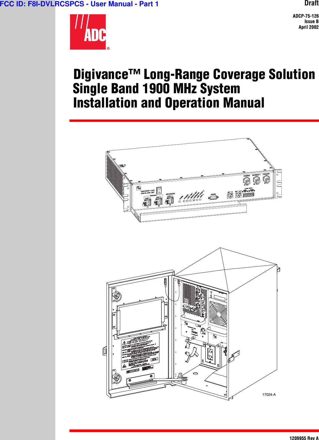
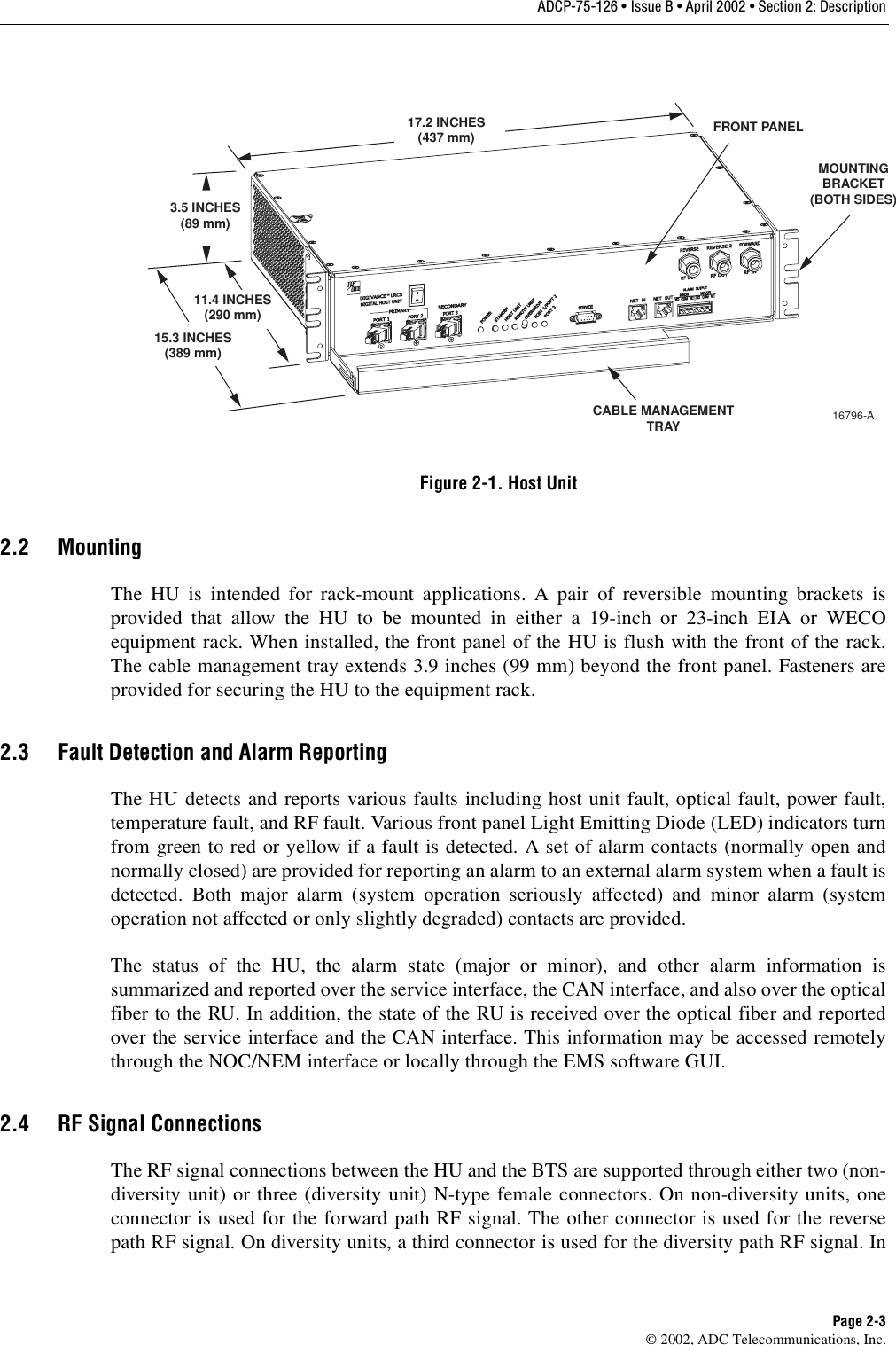
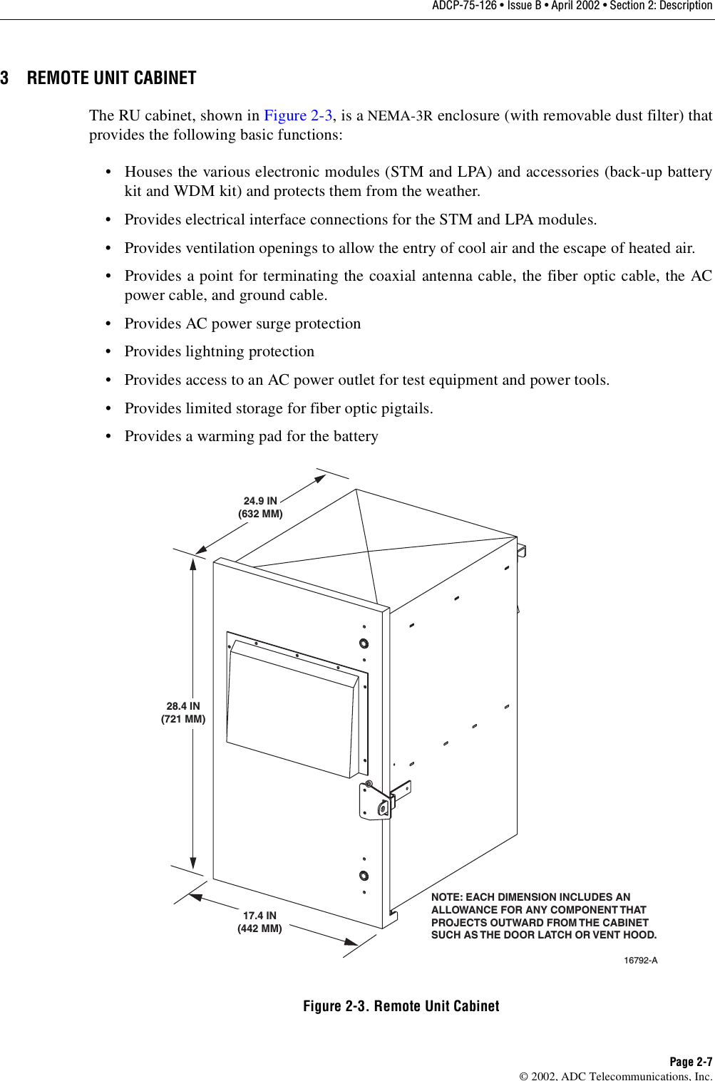
ADC Telecommunications DLC1904B Digivance® Long Range Coverage Solution 1900 MHz User Manual 75126

ADC Telecommunications Inc Digivance® Long Range Coverage Solution 1900 MHz 75126

Manual

DraftADCP-75-126Issue BApril 20021209955 Rev A(Digivance™ Long-Range Coverage Solution Single Band 1900 MHz System(Installation and Operation Manual17024-AFCC ID: F8I-DVLRCSPCS - User Manual - Part 1
DRAFTADCP-75-126Issue BApril 20021209955 Rev A(Digivance™ Long-Range Coverage Solution Single Band 1900 MHz System(Installation and Operation Manual
ADCP-75-126 • Issue B • April 2002 • PrefacePage iiCOPYRIGHT©2002, ADC Telecommunications, Inc.All Rights ReservedPrinted in the U.S.A.REVISION HISTORYTRADEMARK INFORMATIONADC and PowerWorx are registered trademarks of ADC Telecommunications, Inc.Digivance is atrademark of ADC Telecommunications, Inc.Procomm Plus is aregistered trademark of Quarterdeck Corporation.DISCLAIMER OF LIABILITYContents herein are current as of the date of publication. ADC reserves the right to change the contents without prior notice. In noevent shall ADC be liable for any damages resulting from loss of data, loss of use, or loss of profits and ADC furtherdisclaims any and all liability for indirect, incidental, special, consequential or other similar damages. This disclaimer ofliability applies to all products, publications and services during and after the warranty period.This publication may be verified at any time by contacting ADC’s Technical Assistance Center at 1-800-366-3891, extension 73475(in U.S.A. or Canada) or 952-917-3475 (outside U.S.A. and Canada), or by e-mail to technical@adc.comISSUE DATE REASON FOR CHANGEB 04/2002 Original issue.ADC Telecommunications, Inc.P.O. Box 1101, Minneapolis, Minnesota 55440-1101In U.S.A. and Canada: 1-800-366-3891Outside U.S.A. and Canada: (952) 938-8080Fax: (952) 917-1717
ADCP-75-126 • Issue B • April 2002 • PrefacePage iii©2002, ADC Telecommunications, Inc.TABLE OF CONTENTSContent PageABOUT THIS MANUAL  . . . . . . . . . . . . . . . . . . . . . . . . . . . . . . . . . . . . . . . . . . . . . . . . . . . . . . . . . . . . . . . . . . . . . . . .  viiRELATED PUBLICATIONS  . . . . . . . . . . . . . . . . . . . . . . . . . . . . . . . . . . . . . . . . . . . . . . . . . . . . . . . . . . . . . . . . . . . . . .  viiADMONISHMENTS   . . . . . . . . . . . . . . . . . . . . . . . . . . . . . . . . . . . . . . . . . . . . . . . . . . . . . . . . . . . . . . . . . . . . . . . . . . viiiGENERAL SAFETY PRECAUTIONS  . . . . . . . . . . . . . . . . . . . . . . . . . . . . . . . . . . . . . . . . . . . . . . . . . . . . . . . . . . . . . . . . viiiSTANDARDS CERTIFICATION   . . . . . . . . . . . . . . . . . . . . . . . . . . . . . . . . . . . . . . . . . . . . . . . . . . . . . . . . . . . . . . . . . . . . ixLIST OF ACRONYMS AND ABBREVIATIONS . . . . . . . . . . . . . . . . . . . . . . . . . . . . . . . . . . . . . . . . . . . . . . . . . . . . . . . . . . . ixSECTION 1:OVERVIEW1 INTRODUCTION. . . . . . . . . . . . . . . . . . . . . . . . . . . . . . . . . . . . . . . . . . . . . . . . . . . . . . . . . . . . . . . . . . . . . . . . 1-12 SINGLE BAND SYSTEM OVERVIEW  . . . . . . . . . . . . . . . . . . . . . . . . . . . . . . . . . . . . . . . . . . . . . . . . . . . . . . . . . .1-12.1 Basic Components . . . . . . . . . . . . . . . . . . . . . . . . . . . . . . . . . . . . . . . . . . . . . . . . . . . . . . . . . . . . . . . .1-12.2 Base Transceiver Station Interface . . . . . . . . . . . . . . . . . . . . . . . . . . . . . . . . . . . . . . . . . . . . . . . . . . . . .1-22.3  Handset Interface . . . . . . . . . . . . . . . . . . . . . . . . . . . . . . . . . . . . . . . . . . . . . . . . . . . . . . . . . . . . . . . .1-32.4 Local Service Interface. . . . . . . . . . . . . . . . . . . . . . . . . . . . . . . . . . . . . . . . . . . . . . . . . . . . . . . . . . . . .1-32.5 Remote NOC Interface . . . . . . . . . . . . . . . . . . . . . . . . . . . . . . . . . . . . . . . . . . . . . . . . . . . . . . . . . . . . .1-33 SYSTEM FUNCTIONS AND FEATURES  . . . . . . . . . . . . . . . . . . . . . . . . . . . . . . . . . . . . . . . . . . . . . . . . . . . . . . . .1-43.1 Fiber Optic Transport . . . . . . . . . . . . . . . . . . . . . . . . . . . . . . . . . . . . . . . . . . . . . . . . . . . . . . . . . . . . . . 1-43.2 Control and Monitoring Software . . . . . . . . . . . . . . . . . . . . . . . . . . . . . . . . . . . . . . . . . . . . . . . . . . . . . .1-63.3 Fault Detection and Alarm Reporting . . . . . . . . . . . . . . . . . . . . . . . . . . . . . . . . . . . . . . . . . . . . . . . . . . .1-63.4 Powering . . . . . . . . . . . . . . . . . . . . . . . . . . . . . . . . . . . . . . . . . . . . . . . . . . . . . . . . . . . . . . . . . . . . . . 1-73.5 Equipment Mounting and Configuration  . . . . . . . . . . . . . . . . . . . . . . . . . . . . . . . . . . . . . . . . . . . . . . . . .1-7SECTION 2:DESCRIPTION1 INTRODUCTION. . . . . . . . . . . . . . . . . . . . . . . . . . . . . . . . . . . . . . . . . . . . . . . . . . . . . . . . . . . . . . . . . . . . . . . . 2-22 HOST UNIT . . . . . . . . . . . . . . . . . . . . . . . . . . . . . . . . . . . . . . . . . . . . . . . . . . . . . . . . . . . . . . . . . . . . . . . . . . .2-22.1 Primary Components . . . . . . . . . . . . . . . . . . . . . . . . . . . . . . . . . . . . . . . . . . . . . . . . . . . . . . . . . . . . . .2-22.2 Mounting . . . . . . . . . . . . . . . . . . . . . . . . . . . . . . . . . . . . . . . . . . . . . . . . . . . . . . . . . . . . . . . . . . . . . . 2-32.3 Fault Detection and Alarm Reporting . . . . . . . . . . . . . . . . . . . . . . . . . . . . . . . . . . . . . . . . . . . . . . . . . . .2-32.4 RF Signal Connections . . . . . . . . . . . . . . . . . . . . . . . . . . . . . . . . . . . . . . . . . . . . . . . . . . . . . . . . . . . . .2-32.5 RF Signal Level Adjustments. . . . . . . . . . . . . . . . . . . . . . . . . . . . . . . . . . . . . . . . . . . . . . . . . . . . . . . . .2-42.6 Propagation Delay . . . . . . . . . . . . . . . . . . . . . . . . . . . . . . . . . . . . . . . . . . . . . . . . . . . . . . . . . . . . . . . .2-42.7 Optical Connection  . . . . . . . . . . . . . . . . . . . . . . . . . . . . . . . . . . . . . . . . . . . . . . . . . . . . . . . . . . . . . . .2-42.8 Controller Area Network Interface Connection . . . . . . . . . . . . . . . . . . . . . . . . . . . . . . . . . . . . . . . . . . . . .2-42.9 Service Interface Connection. . . . . . . . . . . . . . . . . . . . . . . . . . . . . . . . . . . . . . . . . . . . . . . . . . . . . . . . .2-42.10 Powering . . . . . . . . . . . . . . . . . . . . . . . . . . . . . . . . . . . . . . . . . . . . . . . . . . . . . . . . . . . . . . . . . . . . . . 2-52.11 Cooling  . . . . . . . . . . . . . . . . . . . . . . . . . . . . . . . . . . . . . . . . . . . . . . . . . . . . . . . . . . . . . . . . . . . . . . .2-52.12 User Interface . . . . . . . . . . . . . . . . . . . . . . . . . . . . . . . . . . . . . . . . . . . . . . . . . . . . . . . . . . . . . . . . . . .2-53 REMOTE UNIT CABINET . . . . . . . . . . . . . . . . . . . . . . . . . . . . . . . . . . . . . . . . . . . . . . . . . . . . . . . . . . . . . . . . . .2-7TABLE OF CONTENTS
ADCP-75-126 • Issue B • April 2002 • PrefacePage iv©2002, ADC Telecommunications, Inc.TABLE OF CONTENTSContent Page3.1 Primary Components . . . . . . . . . . . . . . . . . . . . . . . . . . . . . . . . . . . . . . . . . . . . . . . . . . . . . . . . . . . . . . 2-83.2 Mounting . . . . . . . . . . . . . . . . . . . . . . . . . . . . . . . . . . . . . . . . . . . . . . . . . . . . . . . . . . . . . . . . . . . . . . 2-83.3 Module Installation . . . . . . . . . . . . . . . . . . . . . . . . . . . . . . . . . . . . . . . . . . . . . . . . . . . . . . . . . . . . . . . 2-83.4 Fiber Optic Cable Entry  . . . . . . . . . . . . . . . . . . . . . . . . . . . . . . . . . . . . . . . . . . . . . . . . . . . . . . . . . . . . 2-83.5 Antenna Cable Connection . . . . . . . . . . . . . . . . . . . . . . . . . . . . . . . . . . . . . . . . . . . . . . . . . . . . . . . . . . 2-93.6 AC Power Wiring Entry and Grounding . . . . . . . . . . . . . . . . . . . . . . . . . . . . . . . . . . . . . . . . . . . . . . . . . . 2-93.7 Back-up Battery Kit . . . . . . . . . . . . . . . . . . . . . . . . . . . . . . . . . . . . . . . . . . . . . . . . . . . . . . . . . . . . . . . 2-93.8 Ventilation . . . . . . . . . . . . . . . . . . . . . . . . . . . . . . . . . . . . . . . . . . . . . . . . . . . . . . . . . . . . . . . . . . . . 2-103.9 User Interface. . . . . . . . . . . . . . . . . . . . . . . . . . . . . . . . . . . . . . . . . . . . . . . . . . . . . . . . . . . . . . . . . . 2-104 SPECTRUM TRANSPORT MODULE  . . . . . . . . . . . . . . . . . . . . . . . . . . . . . . . . . . . . . . . . . . . . . . . . . . . . . . . . . 2-124.1 Primary Components . . . . . . . . . . . . . . . . . . . . . . . . . . . . . . . . . . . . . . . . . . . . . . . . . . . . . . . . . . . . . 2-134.2 Mounting . . . . . . . . . . . . . . . . . . . . . . . . . . . . . . . . . . . . . . . . . . . . . . . . . . . . . . . . . . . . . . . . . . . . . 2-134.3 Fault Detection and Alarm Reporting . . . . . . . . . . . . . . . . . . . . . . . . . . . . . . . . . . . . . . . . . . . . . . . . . . 2-134.4 Antenna Cable Connection . . . . . . . . . . . . . . . . . . . . . . . . . . . . . . . . . . . . . . . . . . . . . . . . . . . . . . . . . 2-134.5 RF Signal Level Adjustment . . . . . . . . . . . . . . . . . . . . . . . . . . . . . . . . . . . . . . . . . . . . . . . . . . . . . . . . 2-134.6 Optical Connection  . . . . . . . . . . . . . . . . . . . . . . . . . . . . . . . . . . . . . . . . . . . . . . . . . . . . . . . . . . . . . . 2-144.7 Service Interface Connection  . . . . . . . . . . . . . . . . . . . . . . . . . . . . . . . . . . . . . . . . . . . . . . . . . . . . . . . 2-144.8 Powering . . . . . . . . . . . . . . . . . . . . . . . . . . . . . . . . . . . . . . . . . . . . . . . . . . . . . . . . . . . . . . . . . . . . . 2-144.9 Cooling . . . . . . . . . . . . . . . . . . . . . . . . . . . . . . . . . . . . . . . . . . . . . . . . . . . . . . . . . . . . . . . . . . . . . . 2-144.10 User Interface. . . . . . . . . . . . . . . . . . . . . . . . . . . . . . . . . . . . . . . . . . . . . . . . . . . . . . . . . . . . . . . . . . 2-145 LINEAR POWER AMPLIFIER . . . . . . . . . . . . . . . . . . . . . . . . . . . . . . . . . . . . . . . . . . . . . . . . . . . . . . . . . . . . . . 2-165.1 Primary Components . . . . . . . . . . . . . . . . . . . . . . . . . . . . . . . . . . . . . . . . . . . . . . . . . . . . . . . . . . . . . 2-175.2 Mounting . . . . . . . . . . . . . . . . . . . . . . . . . . . . . . . . . . . . . . . . . . . . . . . . . . . . . . . . . . . . . . . . . . . . . 2-175.3 Fault Detection and Alarm Reporting . . . . . . . . . . . . . . . . . . . . . . . . . . . . . . . . . . . . . . . . . . . . . . . . . . 2-185.4 Powering . . . . . . . . . . . . . . . . . . . . . . . . . . . . . . . . . . . . . . . . . . . . . . . . . . . . . . . . . . . . . . . . . . . . . 2-185.5 Cooling . . . . . . . . . . . . . . . . . . . . . . . . . . . . . . . . . . . . . . . . . . . . . . . . . . . . . . . . . . . . . . . . . . . . . . 2-185.6 User Interface. . . . . . . . . . . . . . . . . . . . . . . . . . . . . . . . . . . . . . . . . . . . . . . . . . . . . . . . . . . . . . . . . . 2-186 DIGIVANCE ELEMENT MANAGEMENT SYSTEM  . . . . . . . . . . . . . . . . . . . . . . . . . . . . . . . . . . . . . . . . . . . . . . . . . 2-196.1 Primary Components . . . . . . . . . . . . . . . . . . . . . . . . . . . . . . . . . . . . . . . . . . . . . . . . . . . . . . . . . . . . . 2-196.2 Service Interface Connection  . . . . . . . . . . . . . . . . . . . . . . . . . . . . . . . . . . . . . . . . . . . . . . . . . . . . . . . 2-206.3 NOC Interface Connection  . . . . . . . . . . . . . . . . . . . . . . . . . . . . . . . . . . . . . . . . . . . . . . . . . . . . . . . . . 2-206.4 EMS Software User Interface  . . . . . . . . . . . . . . . . . . . . . . . . . . . . . . . . . . . . . . . . . . . . . . . . . . . . . . . 2-217 SPECIFICATIONS  . . . . . . . . . . . . . . . . . . . . . . . . . . . . . . . . . . . . . . . . . . . . . . . . . . . . . . . . . . . . . . . . . . . . . 2-22SECTION 3:HOST UNIT INSTALLATION1 BEFORE STARTING INSTALLATION . . . . . . . . . . . . . . . . . . . . . . . . . . . . . . . . . . . . . . . . . . . . . . . . . . . . . . . . . . 3-11.1 Tools and Materials. . . . . . . . . . . . . . . . . . . . . . . . . . . . . . . . . . . . . . . . . . . . . . . . . . . . . . . . . . . . . . . 3-11.2 Unpacking and Inspection  . . . . . . . . . . . . . . . . . . . . . . . . . . . . . . . . . . . . . . . . . . . . . . . . . . . . . . . . . . 3-22 OSP FIBER CABLE INSTALLATION GUIDELINES . . . . . . . . . . . . . . . . . . . . . . . . . . . . . . . . . . . . . . . . . . . . . . . . . . 3-23 WDM MOUNTING PROCEDURE (OPTIONAL ACCESSORY) . . . . . . . . . . . . . . . . . . . . . . . . . . . . . . . . . . . . . . . . . . .3-4TABLE OF CONTENTS
ADCP-75-126 • Issue B • April 2002 • PrefacePage v©2002, ADC Telecommunications, Inc.TABLE OF CONTENTSContent Page4 HU MOUNTING PROCEDURE . . . . . . . . . . . . . . . . . . . . . . . . . . . . . . . . . . . . . . . . . . . . . . . . . . . . . . . . . . . . . . .3-65 CHASSIS GROUND CONNECTION . . . . . . . . . . . . . . . . . . . . . . . . . . . . . . . . . . . . . . . . . . . . . . . . . . . . . . . . . . . .3-86 COAXIAL CABLE CONNECTIONS. . . . . . . . . . . . . . . . . . . . . . . . . . . . . . . . . . . . . . . . . . . . . . . . . . . . . . . . . . . . .3-87 OPTICAL CONNECTIONS. . . . . . . . . . . . . . . . . . . . . . . . . . . . . . . . . . . . . . . . . . . . . . . . . . . . . . . . . . . . . . . . . 3-107.1 Optical Connections Without WDM. . . . . . . . . . . . . . . . . . . . . . . . . . . . . . . . . . . . . . . . . . . . . . . . . . . . 3-107.2 Optical Connections With WDM . . . . . . . . . . . . . . . . . . . . . . . . . . . . . . . . . . . . . . . . . . . . . . . . . . . . . . 3-118 CONTROLLER AREA NETWORK CONNECTIONS  . . . . . . . . . . . . . . . . . . . . . . . . . . . . . . . . . . . . . . . . . . . . . . . . . 3-139 SERVICE INTERFACE CONNECTION  . . . . . . . . . . . . . . . . . . . . . . . . . . . . . . . . . . . . . . . . . . . . . . . . . . . . . . . . . 3-1410 EXTERNAL ALARM SYSTEM CONNECTIONS  . . . . . . . . . . . . . . . . . . . . . . . . . . . . . . . . . . . . . . . . . . . . . . . . . . . 3-1511 DC POWER CONNECTIONS . . . . . . . . . . . . . . . . . . . . . . . . . . . . . . . . . . . . . . . . . . . . . . . . . . . . . . . . . . . . . . . 3-16SECTION 4:OPERATION1 BEFORE STARTING OPERATION  . . . . . . . . . . . . . . . . . . . . . . . . . . . . . . . . . . . . . . . . . . . . . . . . . . . . . . . . . . . .4-11.1 Tools and Materials . . . . . . . . . . . . . . . . . . . . . . . . . . . . . . . . . . . . . . . . . . . . . . . . . . . . . . . . . . . . . . .4-11.2 Readiness Check . . . . . . . . . . . . . . . . . . . . . . . . . . . . . . . . . . . . . . . . . . . . . . . . . . . . . . . . . . . . . . . . .4-22 TURN-UP SYSTEM AND VERIFY OPERATION . . . . . . . . . . . . . . . . . . . . . . . . . . . . . . . . . . . . . . . . . . . . . . . . . . . .4-22.1 Turn-Up Procedure. . . . . . . . . . . . . . . . . . . . . . . . . . . . . . . . . . . . . . . . . . . . . . . . . . . . . . . . . . . . . . . . 4-32.2 Download HU and RU System Software  . . . . . . . . . . . . . . . . . . . . . . . . . . . . . . . . . . . . . . . . . . . . . . . . .4-62.3 Determine Forward Path Input Signal Level  . . . . . . . . . . . . . . . . . . . . . . . . . . . . . . . . . . . . . . . . . . . . . .4-72.4 Enter Site Name and Site Number  . . . . . . . . . . . . . . . . . . . . . . . . . . . . . . . . . . . . . . . . . . . . . . . . . . . . 4-102.5 Enter Host Forward Attenuation . . . . . . . . . . . . . . . . . . . . . . . . . . . . . . . . . . . . . . . . . . . . . . . . . . . . . . 4-112.6 Determine Output Signal Level at STM Antenna Port  . . . . . . . . . . . . . . . . . . . . . . . . . . . . . . . . . . . . . . . 4-122.7 Enter Remote Forward Attenuation. . . . . . . . . . . . . . . . . . . . . . . . . . . . . . . . . . . . . . . . . . . . . . . . . . . . 4-132.8 Enter Host Reverse Attenuation . . . . . . . . . . . . . . . . . . . . . . . . . . . . . . . . . . . . . . . . . . . . . . . . . . . . . . 4-152.9 Enter Host Forward and Reverse Delay . . . . . . . . . . . . . . . . . . . . . . . . . . . . . . . . . . . . . . . . . . . . . . . . . 4-17SECTION 5:MAINTENANCE1 SYSTEM MAINTENANCE OVERVIEW. . . . . . . . . . . . . . . . . . . . . . . . . . . . . . . . . . . . . . . . . . . . . . . . . . . . . . . . . .5-11.1 Tools and Materials . . . . . . . . . . . . . . . . . . . . . . . . . . . . . . . . . . . . . . . . . . . . . . . . . . . . . . . . . . . . . . .5-12 FAULT DETECTION AND ALARM REPORTING. . . . . . . . . . . . . . . . . . . . . . . . . . . . . . . . . . . . . . . . . . . . . . . . . . . . 5-23 FAULT ISOLATION AND TROUBLESHOOTING. . . . . . . . . . . . . . . . . . . . . . . . . . . . . . . . . . . . . . . . . . . . . . . . . . . .5-64 TEST PROCEDURES. . . . . . . . . . . . . . . . . . . . . . . . . . . . . . . . . . . . . . . . . . . . . . . . . . . . . . . . . . . . . . . . . . . . 5-114.1 Optical Power Test. . . . . . . . . . . . . . . . . . . . . . . . . . . . . . . . . . . . . . . . . . . . . . . . . . . . . . . . . . . . . . . 5-114.2 Optical Loopback Test  . . . . . . . . . . . . . . . . . . . . . . . . . . . . . . . . . . . . . . . . . . . . . . . . . . . . . . . . . . . . 5-125 MAINTENANCE PROCEDURES . . . . . . . . . . . . . . . . . . . . . . . . . . . . . . . . . . . . . . . . . . . . . . . . . . . . . . . . . . . . . 5-135.1 Scheduled Maintenance . . . . . . . . . . . . . . . . . . . . . . . . . . . . . . . . . . . . . . . . . . . . . . . . . . . . . . . . . . . 5-145.2 Remote Unit Cabinet Filter Cleaning Procedure . . . . . . . . . . . . . . . . . . . . . . . . . . . . . . . . . . . . . . . . . . . 5-145.3 Host Unit Fan Replacement Procedure . . . . . . . . . . . . . . . . . . . . . . . . . . . . . . . . . . . . . . . . . . . . . . . . . 5-15
ADCP-75-126 • Issue B • April 2002 • PrefacePage vi©2002, ADC Telecommunications, Inc.TABLE OF CONTENTSContent Page5.4 Spectrum Transport Module Fan Replacement Procedure . . . . . . . . . . . . . . . . . . . . . . . . . . . . . . . . . . . . 5-175.5 Linear Power Amplifier Fan Replacement Procedure . . . . . . . . . . . . . . . . . . . . . . . . . . . . . . . . . . . . . . . 5-19SECTION 6:GENERAL INFORMATION1 WARRANTY/SOFTWARE  . . . . . . . . . . . . . . . . . . . . . . . . . . . . . . . . . . . . . . . . . . . . . . . . . . . . . . . . . . . . . . . . . 6-12 SOFTWARE SERVICE AGREEMENT  . . . . . . . . . . . . . . . . . . . . . . . . . . . . . . . . . . . . . . . . . . . . . . . . . . . . . . . . . . 6-13 REPAIR/EXCHANGE POLICY . . . . . . . . . . . . . . . . . . . . . . . . . . . . . . . . . . . . . . . . . . . . . . . . . . . . . . . . . . . . . . . 6-14 REPAIR CHARGES. . . . . . . . . . . . . . . . . . . . . . . . . . . . . . . . . . . . . . . . . . . . . . . . . . . . . . . . . . . . . . . . . . . . . . 6-25 REPLACEMENT/SPARE PRODUCTS . . . . . . . . . . . . . . . . . . . . . . . . . . . . . . . . . . . . . . . . . . . . . . . . . . . . . . . . . . 6-26 RETURNED MATERIAL. . . . . . . . . . . . . . . . . . . . . . . . . . . . . . . . . . . . . . . . . . . . . . . . . . . . . . . . . . . . . . . . . . . 6-27 CUSTOMER INFORMATION AND ASSISTANCE. . . . . . . . . . . . . . . . . . . . . . . . . . . . . . . . . . . . . . . . . . . . . . . . . . . 6-3
ADCP-75-126 • Issue B • April 2002 • PrefacePage vii©2002, ADC Telecommunications, Inc.ABOUT THIS MANUALThis installation and operation manual provides the following information:•Anoverview of the Digivance single band 1900 MHz Long-Range Coverage Solution(LRCS).•Adescription of the basic system components including the Host Unit (HU), SpectrumTransport Module (STM), Linear Power Amplifier (LPA), Remote Unit (RU) cabinet, andDigivance Element Management System (EMS).• Installation procedures for the HU.• Procedures for tuning-up the system and verifying that the system is functioning properly.• Procedures for maintaining the system including troubleshooting problems and replacingfaulty components.• Product warranty, repair, return, and replacement information.The procedures for installing the remote unit and for installing and using the EMS software areprovided in other publications which are referenced in the Related Publications section and atappropriate points within this manual.RELATED PUBLICATIONSListed below are all the related manuals, their content, and their publication numbers. Copies ofthese publications can be ordered by contacting the Technical Assistance Center at1-800-366-3891,extension 73475 (in U.S.A. or Canada) or 952-917-3475 (outside U.S.A. andCanada).Digivance LRCS Single Band 800 and 1900 MHz Remote UnitInstallation Instructions 75-122Provides instructions for installing the STM, LPA, and optional battery in theremote unit cabinet and for installing and connecting the fiber optic, coaxial,and AC power cables.Digivance LRCS Single Band Remote Unit Cabinet Installation Instructions 75-117Provides instructions for locating and mounting the remote unit cabinet.Digivance Element Management System Version 2.0 User Manual 75-125Provides instructions for installing the Digivance EMS software and for usingboth the Graphical User Interface (GUI) and the Network Operations Center(NOC) versions of the software.Title/Description ADCP Number
ADCP-75-126 • Issue B • April 2002 • PrefacePage viii©2002, ADC Telecommunications, Inc.ADMONISHMENTSImportant safety admonishments are used throughout this manual to warn of possible hazards topersons or equipment. An admonishment identifies apossible hazard and then explains whatmay happen if the hazard is not avoided. The admonishments —in the form of Dangers,Warnings, and Cautions —must be followed at all times. These warnings are flagged by use ofthe triangular alert icon (seen below), and are listed in descending order of severity of injury ordamage and likelihood of occurrence.GENERAL SAFETY PRECAUTIONSDanger: Danger is used to indicate the presence of ahazard that will cause severe personalinjury, death, or substantial property damage if the hazard is not avoided.Warning: Warning is used to indicate the presence of ahazard that can cause severe personalinjury, death, or substantial property damage if the hazard is not avoided.Caution: Caution is used to indicate the presence of ahazard that will or can cause minorpersonal injury or property damage if the hazard is not avoided.Danger: This equipment uses aClass 1Laser according to FDA/CDRH rules. Laser radiationcan seriously damage the retina of the eye. Do not look into the ends of any optical fiber. Do notlook directly into the optical transceiver of any digital unit or exposure to laser radiation mayresult. An optical power meter should be used to verify active fibers. Aprotective cap or hoodMUST be immediately placed over any radiating transceiver or optical fiber connector to avoidthe potential of dangerous amounts of radiation exposure. This practice also prevents dirtparticles from entering the adapter or connector.Danger: Do not look into the ends of any optical fiber. Exposure to laser radiation may result.Do not assume laser power is turned-off or the fiber is disconnected at the other end.Danger: Wet conditions increase the potential for receiving an electrical shock when installingor using electrically-powered equipment. To prevent electrical shock, never install or useelectrical equipment in awet location or during alightning storm.Warning: The HU is powered by 48 VDC power which is supplied over customer-providedwiring. To prevent electrical shock when installing or modifying the HU power wiring,disconnect the wiring at the power source before working with uninsulated wires or terminals.Caution: Always allow sufficient fiber length to permit routing of patch cords and pigtailswithout severe bends. Fiber optic patch cords or pigtails may be permanently damaged if bentor curved to aradius of less than 2inches (50 mm).
ADCP-75-126 • Issue B • April 2002 • PrefacePage ix©2002, ADC Telecommunications, Inc.STANDARDS CERTIFICATIONFCC:This equipment complies with the applicable sections of Title 47 CFR Part 24.UL/CUL:This equipment complies with UL and CUL 50 Standard for Enclosures forElectrical Equipment. This equipment provides the degree of protection specified by IP43 asdefined in IEC Publication 529.FDA/CDRH:This equipment uses aClass 1LASER according to FDA/CDRH Rules. Thisproduct conforms to all applicable standards of 21 CFR Part 1040.IC:This equipment complies with the applicable sections of RSS-131.LIST OF ACRONYMS AND ABBREVIATIONSThe acronyms and abbreviations used in this manual are detailed in the following list:AC Alternating CurrentASCII American Standard Code for Information InterchangeAtt AttenuationAWG American Wire GaugeBER Bit Error RateBTS Base Transceiver StationCCentigradeCAN Controller Area NetworkCDRH Center for Devices and Radiological HealthCD-ROM Compact Disk Read Only MemoryCOM CommonConfig ConfigurationCUL Canadian Underwriters LaboratoriesDC Direct CurrentDCE Data Communications EquipmentDiv DiversityDTE Data Terminal EquipmentEIA Electronic Industries AssociationEMS Element Management SystemESD Electrostatic DischargeFFahrenheitFCC Federal Communications CommissionFDA Food and Drug AdministrationFSO Free Space OpticsFwd ForwardGFCI Ground Fault Circuit InterrupterGUI Graphical User Interface
ADCP-75-126 • Issue B • April 2002 • PrefacePage x©2002, ADC Telecommunications, Inc.HU Host UnitIC Industry CanadaLED Light Emitting DiodeLPA Linear Power AmplifierLRCS Long-Range Coverage SolutionMHz Mega HertzMPE Maximum Permissible ExposureMTBF Mean Time Between FailureNC Normally ClosedNEM Network Element ManagerNO Normally OpenNOC Network Operations CenterNPT National Pipe TaperedOSP Outside PlantPA Power AmplifierPC Personal ComputerPCS Personal Communications SystemPrg ProgramPwr PowerRev ReverseRF Radio FrequencyRIM Radio Interface ModuleRMA Return Material AuthorizationRU Remote UnitRX Receive or ReceiverSMR Specialized Mobile RadioSTM Spectrum Transport ModuleTX Transmit or TransmitterUL Underwriters LaboratoriesVAC Volts Alternating CurrentVDC Volts Direct CurrentVSWR Vo lta ge Standing Wave RatioWECO Western Electric CompanyWDM Wave Division Multiplexer
ADCP-75-126 • Issue B • April 2002 • Section 1: OverviewPage 1-1©2002, ADC Telecommunications, Inc.SECTION 1: OVERVIEW1 INTRODUCTION. . . . . . . . . . . . . . . . . . . . . . . . . . . . . . . . . . . . . . . . . . . . . . . . . . . . . . . . . . . . . . . . . . . . . . . . 1-12 SINGLE BAND SYSTEM OVERVIEW  . . . . . . . . . . . . . . . . . . . . . . . . . . . . . . . . . . . . . . . . . . . . . . . . . . . . . . . . . .1-12.1 Basic Components . . . . . . . . . . . . . . . . . . . . . . . . . . . . . . . . . . . . . . . . . . . . . . . . . . . . . . . . . . . . . . . .1-12.2 Base Transceiver Station Interface . . . . . . . . . . . . . . . . . . . . . . . . . . . . . . . . . . . . . . . . . . . . . . . . . . . . .1-22.3  Handset Interface . . . . . . . . . . . . . . . . . . . . . . . . . . . . . . . . . . . . . . . . . . . . . . . . . . . . . . . . . . . . . . . .1-32.4 Local Service Interface. . . . . . . . . . . . . . . . . . . . . . . . . . . . . . . . . . . . . . . . . . . . . . . . . . . . . . . . . . . . .1-32.5 Remote NOC Interface . . . . . . . . . . . . . . . . . . . . . . . . . . . . . . . . . . . . . . . . . . . . . . . . . . . . . . . . . . . . .1-33 SYSTEM FUNCTIONS AND FEATURES  . . . . . . . . . . . . . . . . . . . . . . . . . . . . . . . . . . . . . . . . . . . . . . . . . . . . . . . .1-43.1 Fiber Optic Transport . . . . . . . . . . . . . . . . . . . . . . . . . . . . . . . . . . . . . . . . . . . . . . . . . . . . . . . . . . . . . . 1-43.2 Control and Monitoring Software . . . . . . . . . . . . . . . . . . . . . . . . . . . . . . . . . . . . . . . . . . . . . . . . . . . . . .1-63.3 Fault Detection and Alarm Reporting . . . . . . . . . . . . . . . . . . . . . . . . . . . . . . . . . . . . . . . . . . . . . . . . . . .1-63.4 Powering . . . . . . . . . . . . . . . . . . . . . . . . . . . . . . . . . . . . . . . . . . . . . . . . . . . . . . . . . . . . . . . . . . . . . . 1-73.5 Equipment Mounting and Configuration  . . . . . . . . . . . . . . . . . . . . . . . . . . . . . . . . . . . . . . . . . . . . . . . . .1-7_________________________________________________________________________________________________________1 INTRODUCTIONThis section provides basic description, application, and configuration information about theDigivance single band 1900 MHz Long-Range Coverage Solution (LRCS). Throughout thispublication, all items referenced as “accessory items” are not furnished with the basic productand must be purchased separately.2 SINGLE BAND SYSTEM OVERVIEWThe Digivance single band 1900 MHz LRCS is an RF signal transport system that provideslong-range RF coverage in areas where it is impractical to place aBase Transceiver Station(BTS) at the antenna site. High real estate costs and community restrictions on tower andequipment locations often make it difficult to install the BTS at the same location as theantenna. The Digivance LRCS is designed to overcome equipment placement problems byallowing base stations to be hubbed at acentral location while placing remote antennas atoptimum locations with minimal real estate requirements. With the Digivance LRCS, RFsignals can be transported to one or more remote locations to expand coverage into areas notreceiving service or to extend coverage into difficult to reach areas such as canyons, tunnels, orunderground roadways.2.1 Basic ComponentsThe basic components of asingle band Digivance LRCS system and their functions are shownin Figure 1-1. A single band LRCS system consists of aHost Unit (HU) and aRemote Unit(RU). Control and monitoring functions are provided by the Digivance Element ManagementSystem (EMS). On an optional basis, each HU and RU system may be ordered either with orwithout reverse path diversity. In addition, various accessory items including aback-up batterykit (for the RU), aWave Division Multiplexer (WDM) module (for the HU and RU), networkcables (for connecting multiple HU’s together), and EMS cable (for connecting the EMScomputer to the HU) are available separately.
ADCP-75-126 • Issue B • April 2002 • Section 1: OverviewPage 1-2©2002, ADC Telecommunications, Inc.Figure 1-1. System Overview Diagram2.2 Base Transceiver Station InterfaceThe HU is co-located with the BTS and interfaces directly with the BTS over coaxial cables. Inthe forward path, the HU receives RF signals from the BTS. The HU digitizes the RF signalsand then converts them to digital optical signals for transport to the RU. In the reverse path, theHU receives digital optical signals from the RU. The HU converts the digital optical signalsback to RF signals for transmission to the BTS.EBTSEBTSEBTSDIGIVANCE ELEMENTMANAGEMENT SYSTEMRFRFRFHOST UNITHOST UNITHOST UNITREMOTE UNITREMOTE UNITREMOTE UNITNETWORKOPERATIONSCENTER(REMOTE INTERFACE)LAPTOP(LOCAL INTERFACE)DATANETWORKCONTROLLER AREANETWORKRS-232 ASCIIRS-232RS-23216969-BCD-ROM WITH EMSSOFTWARE
ADCP-75-126 • Issue B • April 2002 • Section 1: OverviewPage 1-3©2002, ADC Telecommunications, Inc.2.3  Handset InterfaceThe RU interfaces with the handsets through an antenna. In the reverse path, the RU receives RFsignals from each handset. The RU digitizes the RF signals and then converts them to digitaloptical signals for transport to the HU. In the forward path, the RU receives digital opticalsignals from the HU. The RU converts the optical signals to RF signals for transmission to thehandsets. The RU is connected to an antenna which transmits and receives the handset RFsignals.2.4 Local Service InterfaceLocal communications with an individual Digivance LRCS system is supported through alocalservice interface capability. The primary component of the local interface is aPC-type laptopcomputer loaded with the Digivance Element Management System (EMS) software. The EMSprovides the various control and monitoring functions required for local management of eachLRSC system. The EMS computer can be directly connected to either the HU or RU through thecomputer’s RS-232 port. Operation is effected through the EMS Graphical User Interface(GUI). The GUI consists of aseries of screens from which the user selects the desired option orfunction. An RS-232 service port is provided on both the HU and the RU for connecting theEMS computer.2.5 Remote NOC InterfaceRemote communications between aNetwork Operations Center (NOC) and anetworkedgrouping of multiple Digivance LRCS systems is supported by aremote NOC interfacecapability. The primary component of the remote NOC interface is aPC-type desktop computerloaded with the Digivance Element Management System (EMS) software. In addition to the localmanagement functions described in the previous section, the EMS also provides the variouscontrol and monitoring functions required for remote management of multiple LRSC systemsthrough aNOC.AController Area Network (CAN) port is provided on each HU so that up to twenty-four HU’scan be networked together in daisy-chain fashion and controlled though the same EMScomputer. The EMS computer connects to the networked HU’s through the computer’s RS-232port #1. All HU’s can then be controlled through the same EMS computer.The NOC is connected to the EMS computer through adata network or dial-up modem. TheEMS computer’s RS-232 port #2 interfaces with the data network equipment. The network ordial-up modem equipment must be capable of interfacing with an RS-232 ASCII interface port.At the NOC, control and monitoring of the networked LRCS systems are effected through aNetwork Element Manager (NEM) interface which requires only aVT100 terminal/emulatorfor operation. The NEM interface language consists of simple ASCII text strings. Allcommunications are input as either SET or GET commands which result in ASCII text stringresponses from the specified system or systems. The EMS computer may also be used locally tomanage the networked LRCS systems. Local operation is through the EMS software GUI.
ADCP-75-126 • Issue B • April 2002 • Section 1: OverviewPage 1-4©2002, ADC Telecommunications, Inc.3 SYSTEM FUNCTIONS AND FEATURESThis section describes various system level functions and features of the Digivance LRCS.3.1 Fiber Optic TransportOn an optional basis, the Digivance LRCS is available either with or without reverse pathdiversity. On non-diversity systems that do not use aWDM module, the HU is connected to theRU over apair of single-mode optical fibers. One fiber is used to transport the forward pathoptical signal. The other fiber is used to transport the reverse path optical signal. Because theoptical signal is digital, the input and output RF signal levels at the HU or the RU are notdependent on the level of the optical signal or the length of the optical fiber. Adiagram of thefiber optic transport system for anon-diversity system that does not include the WDM moduleis shown in Figure 1-2.Figure 1-2. Fiber Optic Transport without Diversity and Without WDM ModuleOn diversity systems that do not use aWDM module, the HU is connected to the RU over threesingle-mode optical fibers. One of the optical fibers is used to transport the forward path opticalsignal. Asecond optical fiber is used to transport the primary reverse path optical signal. Thethird optical fiber is used to transport the diversity reverse path optical signal. Adiagram of thefiber optic transport system with the diversity option is shown in Figure 1-3.The maximum length of the optical links is dependent on the loss specifications of the opticalfiber and the losses imposed by the various connectors and splices. The system provides anoptical budget of 25 dB (typical) when used with 9/125 single-mode fiber.BTSHOST UNIT REMOTE UNIT16996-AFORWARD PATHREVERSE PATHCOAXFIBER OPTICLINKEBTSHOST UNIT REMOTE UNIT16996-AFORWARD PATHREVERSE PATHCOAXFIBER OPTICLINK
ADCP-75-126 • Issue B • April 2002 • Section 1: OverviewPage 1-5©2002, ADC Telecommunications, Inc.Figure 1-3. Fiber Optic Transport with Diversity and Without WDM ModuleThe optical wavelengths used in the system are 1550 nm for the forward path and 1310 nm forthe reverse path. Because different wavelengths are used for the forward and reverse paths, apair of bi-directional wavelength division multiplexers (WDM) may be used in applicationswhere it is desirable to combine the forward path and reverse path optical signals on asingleoptical fiber. One WDM may be mounted with the HU and the other WDM mounted with theRU. Adiagram of afiber optic transport system with aWDM application is shown inFigure 1-4.The WDMs are available as accessory items.Figure 1-4. Wavelength Division Multiplexer ApplicationEBTS HOST UNIT REMOTE UNIT16997-AFORWARD PATHPRIMARYREVERSE PATHCOAXFIBER OPTICLINKDIVERSITYREVERSE PATHEBTSHOST UNIT REMOTE UNIT16998-ACOAXFIBER OPTICLINKDIVERSITYREVERSE PATHWDM WDMFORWARD PATHAND PRIMARY REVERSE PATH
ADCP-75-126 • Issue B • April 2002 • Section 1: OverviewPage 1-6©2002, ADC Telecommunications, Inc.Because separate forward and reverse path optical inputs and outputs are provided at the HUand RU, aFree Space Optics (FSO) system (that meets the Digivance LRCS data rateperformance and BER requirements) may be used in applications where it is desirable to bridgean open span and where it is impractical to lay afiber optic cable. One FSO transceiver unit maybe mounted on the HU side of the open span and the other FSO transceiver unit may be mountedon the RU side of the open span. Asystem diagram of an FSO application is shown inFigure 1-5.FSO systems are available from various equipment manufacturers.Figure 1-5. Free Space Optics Application3.2 Control and Monitoring SoftwareThe Digivance EMS software supports system control and monitoring functions for both thelocal and remote service interfaces. The EMS software is stored on aCD-ROM and shippedseparately with each HU. Software installation consists of copying the software files from theCD-ROM to adesignated directory on the hard-drive of the EMS computer. The EMS softwaremay also be copied to the hard-drive of alaptop computer when alocal service interfaceconnection with aspecific HU or RU is required.The EMS software is used to provision and configure the system for operation. This includesselecting asitename, setting alarm thresholds, and setting forward and reverse path RF gainadjustments. The EMS software is also used to get alarm messages (individual or summary),data measurements, or to upgrade the HU/RU system software. All control and monitorfunctions (except software upgrade which can only be done using the EMS software GUI) canbe effected using either the NOC/NEM interface or the EMS software GUI.3.3 Fault Detection and Alarm ReportingLED indicators are provided on the front panel of the HU and on the front panels of the RUmodules to indicate if the system is normal or if afault is detected. In addition, normally openand normally closed alarm contacts (for both major and minor alarms) are provided at the HUfor connection to acustomer-provided external alarm system. All alarms can also be accessedthrough the NOC/NEM interface or the EMS software GUI.EBTSHOST UNIT REMOTE UNIT16999-ACOAXFSOTX/RXFSOTX/RXPRIMARY REVERSE PATHFORWARDPATHFORWARDPATHPRIMARY REVERSE PATHFREE SPACE OPTICS LINK
ADCP-75-126 • Issue B • April 2002 • Section 1: OverviewPage 1-7©2002, ADC Telecommunications, Inc.3.4 PoweringThe HU is powered by ±24 or ±48 Vdc and must be hard-wired to alocal office battery powersource through afuse panel. The RU is powered by 120 or 240 Vac (50 or 60 Hz) and must behard-wired to the AC power source through a20 Amp breaker box. The RU is pre-wired for 120Vac operation but can be converted to 240 Vac operation if required. The RU is equipped with asurge protector to prevent equipment damage from AC power spikes and alighting protector toprevent equipment damage from lighting surges. A120 Vac outlet is provided within the RUcabinet for powering for test equipment or power tools. On an optional basis, aback-up batterykit is available for the RU. The battery-backup system powers the RU if the AC power source isdisconnected or fails.3.5 Equipment Mounting and ConfigurationThe HU is designed for mounting in anon-condensing indoor environment such as inside awiring closet or within an environmentally-controlled cabinet. The HU is intended for rack-mount applications and may mounted in either a19- or 23-inch WECO or EIA equipment rack,usually within 20 feet of the BTS.The RU is designed for mounting in either an indoor or outdoor environment. The RU consistsof aSpectrum Transport Module (STM), aLinear Power Amplifier (LPA) module, and aself-contained cabinet which houses the modular components and protects them from the elements.The RU cabinet is weather-tight but contact with salt-air mist should be avoided as it maydegrade the MTBF of the product. The cabinet can be mounted from aflat-vertical surface orfrom autility pole (requires pole-mount kit). Slots are provided within the cabinet for mountingthe STM and LPA modules. Astorage spool is provided for storing short lengths of excess fiberslack. Abracket is provided for mounting aWDM module (accessory item). Atray with aheated base is provided for mounting the back-up battery (accessory item).
ADCP-75-126 • Issue B • April 2002 • Section 1: OverviewPage 1-8©2002, ADC Telecommunications, Inc.Blank
ADCP-75-126 • Issue B • April 2002 • Section 2: DescriptionPage 2-1©2002, ADC Telecommunications, Inc.SECTION 2: DESCRIPTION1 INTRODUCTION. . . . . . . . . . . . . . . . . . . . . . . . . . . . . . . . . . . . . . . . . . . . . . . . . . . . . . . . . . . . . . . . . . . . . . . . 2-22 HOST UNIT . . . . . . . . . . . . . . . . . . . . . . . . . . . . . . . . . . . . . . . . . . . . . . . . . . . . . . . . . . . . . . . . . . . . . . . . . . .2-22.1 Primary Components . . . . . . . . . . . . . . . . . . . . . . . . . . . . . . . . . . . . . . . . . . . . . . . . . . . . . . . . . . . . . .2-22.2 Mounting . . . . . . . . . . . . . . . . . . . . . . . . . . . . . . . . . . . . . . . . . . . . . . . . . . . . . . . . . . . . . . . . . . . . . . 2-32.3 Fault Detection and Alarm Reporting . . . . . . . . . . . . . . . . . . . . . . . . . . . . . . . . . . . . . . . . . . . . . . . . . . .2-32.4 RF Signal Connections . . . . . . . . . . . . . . . . . . . . . . . . . . . . . . . . . . . . . . . . . . . . . . . . . . . . . . . . . . . . .2-32.5 RF Signal Level Adjustments. . . . . . . . . . . . . . . . . . . . . . . . . . . . . . . . . . . . . . . . . . . . . . . . . . . . . . . . .2-42.6 Propagation Delay . . . . . . . . . . . . . . . . . . . . . . . . . . . . . . . . . . . . . . . . . . . . . . . . . . . . . . . . . . . . . . . .2-42.7 Optical Connection  . . . . . . . . . . . . . . . . . . . . . . . . . . . . . . . . . . . . . . . . . . . . . . . . . . . . . . . . . . . . . . .2-42.8 Controller Area Network Interface Connection . . . . . . . . . . . . . . . . . . . . . . . . . . . . . . . . . . . . . . . . . . . . .2-42.9 Service Interface Connection. . . . . . . . . . . . . . . . . . . . . . . . . . . . . . . . . . . . . . . . . . . . . . . . . . . . . . . . .2-42.10 Powering . . . . . . . . . . . . . . . . . . . . . . . . . . . . . . . . . . . . . . . . . . . . . . . . . . . . . . . . . . . . . . . . . . . . . . 2-52.11 Cooling  . . . . . . . . . . . . . . . . . . . . . . . . . . . . . . . . . . . . . . . . . . . . . . . . . . . . . . . . . . . . . . . . . . . . . . .2-52.12 User Interface . . . . . . . . . . . . . . . . . . . . . . . . . . . . . . . . . . . . . . . . . . . . . . . . . . . . . . . . . . . . . . . . . . .2-53 REMOTE UNIT CABINET . . . . . . . . . . . . . . . . . . . . . . . . . . . . . . . . . . . . . . . . . . . . . . . . . . . . . . . . . . . . . . . . . .2-73.1 Primary Components . . . . . . . . . . . . . . . . . . . . . . . . . . . . . . . . . . . . . . . . . . . . . . . . . . . . . . . . . . . . . .2-83.2 Mounting . . . . . . . . . . . . . . . . . . . . . . . . . . . . . . . . . . . . . . . . . . . . . . . . . . . . . . . . . . . . . . . . . . . . . . 2-83.3 Module Installation . . . . . . . . . . . . . . . . . . . . . . . . . . . . . . . . . . . . . . . . . . . . . . . . . . . . . . . . . . . . . . .2-83.4 Fiber Optic Cable Entry. . . . . . . . . . . . . . . . . . . . . . . . . . . . . . . . . . . . . . . . . . . . . . . . . . . . . . . . . . . . .2-83.5 Antenna Cable Connection  . . . . . . . . . . . . . . . . . . . . . . . . . . . . . . . . . . . . . . . . . . . . . . . . . . . . . . . . . .2-93.6 AC Power Wiring Entry and Grounding  . . . . . . . . . . . . . . . . . . . . . . . . . . . . . . . . . . . . . . . . . . . . . . . . . .2-93.7 Back-up Battery Kit  . . . . . . . . . . . . . . . . . . . . . . . . . . . . . . . . . . . . . . . . . . . . . . . . . . . . . . . . . . . . . . . 2-93.8 Ventilation  . . . . . . . . . . . . . . . . . . . . . . . . . . . . . . . . . . . . . . . . . . . . . . . . . . . . . . . . . . . . . . . . . . . . 2-103.9 User Interface . . . . . . . . . . . . . . . . . . . . . . . . . . . . . . . . . . . . . . . . . . . . . . . . . . . . . . . . . . . . . . . . . . 2-104 SPECTRUM TRANSPORT MODULE . . . . . . . . . . . . . . . . . . . . . . . . . . . . . . . . . . . . . . . . . . . . . . . . . . . . . . . . . . 2-124.1 Primary Components . . . . . . . . . . . . . . . . . . . . . . . . . . . . . . . . . . . . . . . . . . . . . . . . . . . . . . . . . . . . . 2-134.2 Mounting . . . . . . . . . . . . . . . . . . . . . . . . . . . . . . . . . . . . . . . . . . . . . . . . . . . . . . . . . . . . . . . . . . . . . 2-134.3 Fault Detection and Alarm Reporting . . . . . . . . . . . . . . . . . . . . . . . . . . . . . . . . . . . . . . . . . . . . . . . . . . 2-134.4 Antenna Cable Connection  . . . . . . . . . . . . . . . . . . . . . . . . . . . . . . . . . . . . . . . . . . . . . . . . . . . . . . . . . 2-134.5 RF Signal Level Adjustment  . . . . . . . . . . . . . . . . . . . . . . . . . . . . . . . . . . . . . . . . . . . . . . . . . . . . . . . . 2-134.6 Optical Connection  . . . . . . . . . . . . . . . . . . . . . . . . . . . . . . . . . . . . . . . . . . . . . . . . . . . . . . . . . . . . . . 2-144.7 Service Interface Connection. . . . . . . . . . . . . . . . . . . . . . . . . . . . . . . . . . . . . . . . . . . . . . . . . . . . . . . . 2-144.8 Powering . . . . . . . . . . . . . . . . . . . . . . . . . . . . . . . . . . . . . . . . . . . . . . . . . . . . . . . . . . . . . . . . . . . . . 2-144.9 Cooling  . . . . . . . . . . . . . . . . . . . . . . . . . . . . . . . . . . . . . . . . . . . . . . . . . . . . . . . . . . . . . . . . . . . . . . 2-144.10 User Interface . . . . . . . . . . . . . . . . . . . . . . . . . . . . . . . . . . . . . . . . . . . . . . . . . . . . . . . . . . . . . . . . . . 2-145 LINEAR POWER AMPLIFIER  . . . . . . . . . . . . . . . . . . . . . . . . . . . . . . . . . . . . . . . . . . . . . . . . . . . . . . . . . . . . . . 2-165.1 Primary Components . . . . . . . . . . . . . . . . . . . . . . . . . . . . . . . . . . . . . . . . . . . . . . . . . . . . . . . . . . . . . 2-175.2 Mounting . . . . . . . . . . . . . . . . . . . . . . . . . . . . . . . . . . . . . . . . . . . . . . . . . . . . . . . . . . . . . . . . . . . . . 2-175.3 Fault Detection and Alarm Reporting . . . . . . . . . . . . . . . . . . . . . . . . . . . . . . . . . . . . . . . . . . . . . . . . . . 2-185.4 Powering . . . . . . . . . . . . . . . . . . . . . . . . . . . . . . . . . . . . . . . . . . . . . . . . . . . . . . . . . . . . . . . . . . . . . 2-185.5 Cooling  . . . . . . . . . . . . . . . . . . . . . . . . . . . . . . . . . . . . . . . . . . . . . . . . . . . . . . . . . . . . . . . . . . . . . . 2-185.6 User Interface . . . . . . . . . . . . . . . . . . . . . . . . . . . . . . . . . . . . . . . . . . . . . . . . . . . . . . . . . . . . . . . . . . 2-18Content Page
ADCP-75-126 • Issue B • April 2002 • Section 2: DescriptionPage 2-2©2002, ADC Telecommunications, Inc.6 DIGIVANCE ELEMENT MANAGEMENT SYSTEM  . . . . . . . . . . . . . . . . . . . . . . . . . . . . . . . . . . . . . . . . . . . . . . . . . 2-196.1 Primary Components . . . . . . . . . . . . . . . . . . . . . . . . . . . . . . . . . . . . . . . . . . . . . . . . . . . . . . . . . . . . . 2-196.2 Service Interface Connection  . . . . . . . . . . . . . . . . . . . . . . . . . . . . . . . . . . . . . . . . . . . . . . . . . . . . . . . 2-206.3 NOC Interface Connection  . . . . . . . . . . . . . . . . . . . . . . . . . . . . . . . . . . . . . . . . . . . . . . . . . . . . . . . . . 2-206.4 EMS Software User Interface  . . . . . . . . . . . . . . . . . . . . . . . . . . . . . . . . . . . . . . . . . . . . . . . . . . . . . . . 2-217 SPECIFICATIONS  . . . . . . . . . . . . . . . . . . . . . . . . . . . . . . . . . . . . . . . . . . . . . . . . . . . . . . . . . . . . . . . . . . . . . 2-22_________________________________________________________________________________________________________1 INTRODUCTIONThis section describes the basic components of the Digivance 1900 MHz LRCS systemincluding the Host Unit (HU), the Remote Unit (RU), and the Element Management System(EMS). The RU is an assembly that consists of acabinet, aSpectrum Transport Module (STM),and aLinear Power Amplifier (LPA) module. For clarity, the various components that comprisethe RU are described separately.2 HOST UNITThe HU, shown in Figure 2-1,serves as the BTS servicing unit for the Digivance LRCS. TheHU provides the following basic functions:• Provides an adjustable RF interface with the BTS.• Provides afiber optic interface with the RU.• Digitizes the forward path composite RF signal.•Convertsthe digitized forward path RF signal to adigital optical signal.•Convertsthe digitized reverse path optical signal to adigitized RF signal.•Convertsthe digitized reverse path RF signal to acomposite RF signal.• Signals alarm information to an external alarm system through relay contact closures• Provides an RS-232 interface for connecting the EMS computer.• Provides aCAN interface for networking multiple HUs.2.1 Primary ComponentsThe HU consists of an electronic circuit board assembly and afan assembly that are mountedwithin apowder-coated sheet metal enclosure. The enclosure provides amounting point for thecircuit board and fan assemblies and controls RF emissions. The only user-replaceablecomponent is the fan assembly. The HU is designed for use within anon-condensing indoorenvironment such as inside awiring closet or cabinet. All controls, connectors, and indicators(except the power terminal strip) are mounted on the HU front panel for convenient access.Cable management functions for the coaxial cables and copper wiring are provided by acablemanagement tray that extends outward from the HU front panel.
ADCP-75-126 • Issue B • April 2002 • Section 2: DescriptionPage 2-3©2002, ADC Telecommunications, Inc.Figure 2-1. Host Unit2.2 MountingThe HU is intended for rack-mount applications. Apair of reversible mounting brackets isprovided that allow the HU to be mounted in either a19-inch or 23-inch EIA or WECOequipment rack. When installed, the front panel of the HU is flush with the front of the rack.The cable management tray extends 3.9 inches (99 mm) beyond the front panel. Fasteners areprovided for securing the HU to the equipment rack.2.3 Fault Detection and Alarm ReportingThe HU detects and reports various faults including host unit fault, optical fault, power fault,temperature fault, and RF fault. Various front panel Light Emitting Diode (LED) indicators turnfrom green to red or yellow if afault is detected. Aset of alarm contacts (normally open andnormally closed) are provided for reporting an alarm to an external alarm system when afault isdetected. Both major alarm (system operation seriously affected) and minor alarm (systemoperation not affected or only slightly degraded) contacts are provided.The status of the HU, the alarm state (major or minor), and other alarm information issummarized and reported over the service interface, the CAN interface, and also over the opticalfiber to the RU. In addition, the state of the RU is received over the optical fiber and reportedover the service interface and the CAN interface. This information may be accessed remotelythrough the NOC/NEM interface or locally through the EMS software GUI.2.4 RF Signal ConnectionsThe RF signal connections between the HU and the BTS are supported through either two (non-diversity unit) or three (diversity unit) N-type female connectors. On non-diversity units, oneconnector is used for the forward path RF signal. The other connector is used for the reversepath RF signal. On diversity units, athird connector is used for the diversity path RF signal. In17.2 INCHES(437 mm)3.5 INCHES(89 mm)11.4 INCHES(290 mm)15.3 INCHES(389 mm)FRONT PANELCABLE MANAGEMENTTRAYMOUNTINGBRACKET(BOTH SIDES)16796-A
ADCP-75-126 • Issue B • April 2002 • Section 2: DescriptionPage 2-4©2002, ADC Telecommunications, Inc.most installations, it is usually necessary to install an external attenuator in the forward path linkbetween the HU and the BTS. The HU should be as close as possible to the BTS to minimizecable losses.2.5 RF Signal Level AdjustmentsThe HU is equipped with several attenuators for adjusting the signal levels of the forward andreverse path RF signals. The attenuators provide an attenuation adjustment range of 0to 30 dBand can be set in 1dB increments. The attenuators are software controlled and are adjustedthrough the NOC/NEM interface or the EMS software GUI.The host forward path attenuator adjusts the level of the input RF signal to the HU. Using theforward path attenuator, an input signal with anominal composite signal level of –10 dBm to–40 dBm can be adjusted to produce maximum power output. An external attenuator isrequired if the input signal level is greater than –10 dBm.The host reverse path attenuator adjusts the level of the output RF signal and will add from0dB of gain (attenuator set to 30 dB) to 30 dB of gain (attenuator set to 0dB) to the outputsignal at the HU. The host diversity reverse path attenuator provides the same function as thehost reverse path attenuator but for the diversity reverse path.2.6 Propagation DelayThe HU forward, reverse, and diversity reverse path propagation delays may be adjusted in 1µsincrements within arange of 0–63 µs. The propagation delay is software controlled and may beadjusted through the NOC/NEM interface or the EMS software GUI.2.7 Optical ConnectionOptical connections between the HU and the RU (STM) are supported through either two (non-diversity unit) or three (diversity unit) SC-type optical connector ports. On non-diversity units,one port is used for connecting the forward path optical signal and the other port is used forconnecting the primary reverse path optical signal. On diversity units, athird optical port is usedfor connecting the diversity reverse path optical signal.2.8 Controller Area Network Interface ConnectionController Area Network (CAN) interface connections between multiple HUs are supported byapair of RJ-45 jacks. One of the jacks is designated as the network IN port and the other jack isdesignated as the network OUT port. The CAN interface allows up to 24 HUs to be connectedtogether (in daisy-chain fashion) and controlled through asingle Digivance EMS computer.2.9 Service Interface ConnectionThe service interface connection between the HU and the Digivance EMS computer issupported by asingle DB-9 female connector. The service connector provides an RS-232 DTEinterface. When multiple HUs are networked together, the supporting EMS computer may beconnected to the service connector of any one of the networked HUs.
ADCP-75-126 • Issue B • April 2002 • Section 2: DescriptionPage 2-5©2002, ADC Telecommunications, Inc.2.10 PoweringThe HU is powered by ±24 or ±48 Vdc power. The power is fed to the HU through ascrew-down type terminal strip located on the rear side of the unit. Power to the HU must be suppliedthrough afuse panel such as the 20 position PowerWorx fuse panel (available separately). Thepower circuit for each HU must be protected with a 3 Amp GMT fuse. An On/Off switch isprovided on the HU front panel.2.11 CoolingContinuous airflow for cooling is provided by dual fans mounted on the right side of the HUhousing. Aminimum of 3inches (76 mm) of clearance space must be provided on both the leftand right sides of the HU for air intake and exhaust. An alarm is provided if ahigh temperaturecondition (>50º C/122º F) occurs. The fans may be field-replaced if either fan fails.2.12 User InterfaceThe HU user interface consists of the various connectors, switches, terminals, and LEDs that areprovided on the HU front and rear panels. The HU user interface points are indicated inFigure 2-2 and described in Table 2-1.Figure 2-2. Host Unit User InterfaceTable 2-1. Host Unit User InterfaceREF NOUSER INTERFACE DESIGNATION DEVICE FUNCTIONALDESCRIPTION11/0 On/Offrockerswitch Provides DC power on/off control.2PORT1SCconnector(single-mode) Connection point for the forward path opticalfiber.(1) DC POWER ON/OFF SWITCHNOTE: SHOWN  WITHOUTCABLE MANAGEMENT TRAY(2)PORT 1 (3)PORT 2 (4)PORT 3 (REFERENCEITEMS 5 - 11)LED INDICATORS(12) SERVICEINTERFACECONNECTOR(13) NET INCONNECTOR (14) NET OUTCONNECTOR (15) ALARMOUTPUTCONNECTOR(16) REVERSERF OUT (17) REVERSE 2RF OUT (18) FORWARDRF IN16800-A
ADCP-75-126 • Issue B • April 2002 • Section 2: DescriptionPage 2-6©2002, ADC Telecommunications, Inc.3PORT2SCconnector(single-mode) Connection point for the reverse path primaryoptical fiber.4PORT3(diversity unit only) SC connector(single-mode) Connection point for the reverse path diversityoptical fiber.5 POWER Multi-colored LED(green/yellow)Indicates if the HU is powered (green) or unpow-ered (off). See Note.6 STANDBY Multi-colored LED(green/yellow/red)Indicates if the system is in the Normal (off),Standby (blinking green), Test (blinking red), orProgram Load (blinking yellow) state. See Note.7 HOST UNIT Multi-colored LED(green/yellow/red)Indicates if the HU is normal (green), overheated(yellow), or faulty (red). See Note.8REMOTEUNIT Multi-colored LED(green/yellow/red)Indicates if no alarms (green), aminor alarm(yellow), or amajor alarm (red) is detected at theRU. See Note.9 DRIVE Multi-colored LED(green/yellow/red)Indicates if the level of the RF input signal to theHU is normal (green), low (yellow), or high(red). See Note.10 PORT 1/PORT 2 Multi-colored LED(green/yellow/red)Indicates if the reverse path optical signalreceived from the RU is normal (green), if no sig-nal is detected (red), or if errors are detected(red). See Note.11 PORT 3(diversity unit only)Multi-colored LED(green/yellow)Indicates if the diversity reverse path optical sig-nal received from the RU is normal (green), if nosignal is detected (yellow), or if errors aredetected (yellow). See Note.12 SERVICE DB-9 connector(female) Connection point for the RS-232 service inter-face cable.13 NET IN RJ-45 jack (female) Connection point for the CAN interface inputcable.14 NET OUT RJ-45 jack (female) Connection point for the CAN interface outputcable.15 ALARM OUTPUT Screw-type terminalconnector (14–26AWG)Connection point for an external alarm system.Includes normally open (NO), normally closed(NC), and common (COM) wiring connections.16 REVERSE RF OUT N-type female RFcoaxial connector Connection point for the primary reverse path RFcoaxial cable.17 REVERSE 2RF OUT N-type female RFcoaxial connector Connection point for the diversity reverse pathRF coaxial cable.18 FORWARD RF IN N-type female RFcoaxial connector Connection point for the forward path RF coaxialcable.POWER 24–48 VDC(Rear side -not shown) Screw-type terminalstrip Connection point for the DC power wiring.Note: Amore detailed description of LED operation is provided in Section 5.Table 2-1. Host Unit User Interface, continuedREF NOUSER INTERFACE DESIGNATION DEVICE FUNCTIONALDESCRIPTION
ADCP-75-126 • Issue B • April 2002 • Section 2: DescriptionPage 2-7©2002, ADC Telecommunications, Inc.3 REMOTE UNIT CABINETThe RU cabinet, shown in Figure 2-3,is aNEMA-3R enclosure (with removable dust filter) thatprovides the following basic functions:• Houses the various electronic modules (STM and LPA) and accessories (back-up batterykit and WDM kit) and protects them from the weather.• Provides electrical interface connections for the STM and LPA modules.• Provides ventilation openings to allow the entry of cool air and the escape of heated air.• Provides apoint for terminating the coaxial antenna cable, the fiber optic cable, the ACpower cable, and ground cable.• Provides AC power surge protection• Provides lightning protection• Provides access to an AC power outlet for test equipment and power tools.• Provides limited storage for fiber optic pigtails.• Provides awarming pad for the batteryFigure 2-3. Remote Unit Cabinet16792-A24.9 IN(632 MM)28.4 IN(721 MM)17.4 IN(442 MM)NOTE: EACH DIMENSION INCLUDES ANALLOWANCE FOR ANY COMPONENT THATPROJECTS OUTWARD FROM THE CABINETSUCH AS THE DOOR LATCH OR VENT HOOD.
ADCP-75-126 • Issue B • April 2002 • Section 2: DescriptionPage 2-8©2002, ADC Telecommunications, Inc.3.1 Primary ComponentsThe RU cabinet consists of the enclosure, amounting shelf for the STM and LPA modules, anAC power interface, alightning protector, amounting shelf for the back-up battery accessory, afiber storage spool, and amounting bracket for the WDM accessory. The RU cabinet is designedfor use in either an outdoor or indoor environment. Opening the hinged door provides full heightand width access to the interior of the enclosure to facilitate module and cable installation.The enclosure is constructed of heavy gauge aluminum and is painted putty white for corrosionprotection. Connection and entry points are provided in the bottom of the enclosure for theantenna coaxial cable, fiber optic cable, and AC power cable. Vent openings are provided in thedoor and the rear side of the enclosure to permit air exchange for cooling. The RU cabinet isweather-tight but contact with salt-air mist should be avoided as it may degrade the Mean TimeBetween Failure (MTBF) of the product. Drain holes in the bottom of the cabinet allow anymoisture that does enter the cabinet to drain out. The cabinet door is equipped with asturdylatch so that the enclosure may be padlocked to prevent unauthorized entry. Adoor open switchis provided so that amajor alarm is generated whenever the cabinet door is opened.3.2 MountingThe RU cabinet may be mounted on aflat vertical surface (such as the side of building) or on autility pole. Aspecial mounting bracket is provided with each enclosure. Installation consists ofsecuring the bracket to the mounting surface and then hanging the enclosure from the bracket.The mounting bracket may be attached to avariety of surfaces such as wood, concrete, ormasonry. Various fasteners including hex-head capscrews, tee-nuts, and concrete anchors areprovided. Aseparate pole-mounting kit (accessory item) is available for attaching the mountingbracket to autility pole.3.3 Module InstallationAmounting shelf is provided within the RU cabinet for installing the STM and LPA modules.The mounting shelf includes tracks that guide each module into the installed position. Separatemounting locations are provided for each type of module. Two D-sub connectors (one male, onefemale) are located at the rear of the mounting shelf. Each mounting shelf connector mates withacorresponding D-sub connector located on the rear side of each module. Awiring harnesslinks the mounting shelf connectors together. The connectors and the attached wiring harnessprovide the electrical interface between the STM and LPA modules. The modules are held in theinstalled position with captive screws.3.4 Fiber Optic Cable EntryAplastic cord connector is provided in the exterior bottom side of the RU cabinet for routing afiber optic cable into the enclosure. The cord connector provides cable strain relief and awatertight seal at the fiber optic cable entry point. As the connector nut is tightened, asoftneoprene bushing compresses to tightly grip the cable without applying excessive force to thefibers. The cord connector can accommodate cables that range from 0.375 to 0.875 inches (10 to
ADCP-75-126 • Issue B • April 2002 • Section 2: DescriptionPage 2-9©2002, ADC Telecommunications, Inc.23 mm) in diameter. Aspool is provided directly above the fiber optic cable entry hole forstoring excess pigtail slack.In atypical installation, the connectorized end of amulit-fiber outside plant cable is routed intothe enclosure through the cord connector and the individual fibers are broken out into pigtails.The pigtails are connected to the optical ports on the STM and the excess pigtail slack is storedon the fiber storage spool. The stub end of the cable is routed to an external splice enclosure (notprovided) for splicing to the fiber optic cable.3.5 Antenna Cable ConnectionAn N-type female connector is provided on the exterior bottom side of the RU cabinet forconnecting the primary antenna coaxial cable. The exterior connector is on the surge side of alightning protector that is mounted on the interior bottom side of the enclosure. On the inside ofthe enclosure, asecond N-type female connector is provided on the protected side of thelightning protector. Acoaxial jumper cable (included with the enclosure) is used for connectingthe protected side N-type connector to the ANTENNA port on the STM.Adiversity lightning protector kit (accessory item) is available if adiversity STM is mounted inthe enclosure. Adiversity lightning protector (Catalog #DGVL-000010LADK) is required if adiversity antenna is installed. Ahole is provided in the bottom of the enclosure for mounting thediversity lightning protector.3.6 AC Power Wiring Entry and GroundingA3/4-inch NPT threaded hole is provided in the exterior bottom side of the RU cabinet forconnecting astandard 3/4-inch AC conduit fitting to the enclosure. A3/4-inch to 1/2-inchreducer is also included with the enclosure if 1/2-inch conduit is preferred over 3/4-inchconduit. The conduit should be installed between the enclosure and an external 20 Amp breakerbox (not provided) and all AC power wiring (three wires required) should be run within theconduit. Three lead wires (Hot, Neutral, and Ground) are provided within the enclosure forconnection to the AC wiring. Three wire nuts are included with the enclosure for completing theconnection. Agrounding lug is provided on the underside of the enclosure for connecting theRU cabinet to an earth ground source.The standard RU cabinet is equipped with a120 VAC Ground Fault Circuit Interrupter (GFCI)outlet and should only be wired for operation on 120 VAC current. The cabinet may be re-wiredfor 240 VAC if required.3.7 Back-up Battery KitAback-up battery kit (accessory item) is available when the application requires that the systemremain operational during an AC power outage. Atray is provided within the enclosure formounting the battery. The battery tray includes aheating pad that keeps the battery warm duringcold weather. Atemperature sensor regulates the operation of the heating pad and acircuitbreaker provides overcurrent protection. The back-up battery kit includes awiring harness forconnecting the battery to the STM. During normal operation, the STM provides charging
ADCP-75-126 • Issue B • April 2002 • Section 2: DescriptionPage 2-10©2002, ADC Telecommunications, Inc.current to maintain the battery charge level. During an AC power outage, the battery providesDC power to the STM to maintain system operation. The battery can maintain operation of theRU for approximately 1hour at 50 Watts.3.8 VentilationVent openings are provided in the door and the rear side of the RU cabinet to permit airexchange for cooling. Air enters the enclosure through the opening in the door. Afilter on theinside of the door removes dirt particles so that only clean air enters the enclosure. Bothmodules have cooling fans. The STM has arear mounted fan that pulls air through the moduleand exhausts it toward the rear of the enclosure. The heated air exits through an opening in therear side of the enclosure. The LPA works in asimilar manner except it also has afan on thefront to help draw air into the module.3.9 User InterfaceThe RU cabinet user interface consists of the various connectors, fittings, outlets, and switchesthat are provided on both the interior and exterior of the enclosure. The RU cabinet userinterface points are described in Table 2-2 and indicated in Figure 2-4.Table 2-2. Remote Unit Cabinet User InterfaceREF NO DEVICE FUNCTIONAL DESCRIPTION1Airinlet filter A reusable filter that prevents the entry of dirt particles when out-side air is pulled into the cabinet for cooling.2ACpower cord Provides AC power to the STM.3 Circuit breaker reset switch Used to reset the battery heater circuit following correction of anovercurrent condition.4Doorswitch Indicates to the fault detection and alarm reporting system if thecabinet door is open (major alarm) or closed.5 Module mounting shelf Provides amounting point for the STM and LPA modules.6Batterytray Provides amounting point for the back-up battery (when used).7120Vac GFCI outlet(standard)Standard 120 Vac GFCI outlet for connecting AC power tools ortest equipment.8Fiberslack spool Provides astorage place for excess fiber pigtail slack.9 Lightning protector Provides lightning surge protection for the antenna connection.10 Fiber cable connector Provides both an entry point and strain relief for the fiber opticcable.11 3/4-inch NPT threaded hole Provides aconnection point for a3/4-inch AC conduit fitting.12 Grounding lug Provides aconnection point for an external grounding cable.
ADCP-75-126 • Issue B • April 2002 • Section 2: DescriptionPage 2-11©2002, ADC Telecommunications, Inc.Figure 2-4. Remote Unit Cabinet User InterfaceBOTTOM VIEWOF CABINET(7) GFCI OUTLET(4) DOORSWITCH(1) AIR INLET FILTER(2) AC POWER CORD(3) CIRCUIT BREAKERRESET SWITCH(5) MODULE MOUNTINGSHELF(6) BATTERY TRAY(8) FIBER SLACKSPOOL(9) LIGHTNINGPROTECTOR(10) FIBER CABLECONNECTOR (11) THREADS FORAC CONDUIT FITTING (12) GROUNDING LUG16793-B

Navigation menu