ADC Telecommunications DSR1904A Digivance® Software Defined Radio User Manual 75198p1
ADC Telecommunications Inc Digivance® Software Defined Radio 75198p1
SDR User Manual

ADCP-75-198 • Issue 1 • October 2005
1340297 Rev A Page 1
© 2005, ADC Telecommunications, Inc.
Digivance® SDR
PCIx Host Card
Installation Instructions
INTRODUCTION . . . . . . . . . . . . . . . . . . . . . . . . . . . . . . . . . . . . . . . . . . . . . . . . . . . . . . . . . . . . . . . . . . . . . . . . . . . . . 2
Revision History . . . . . . . . . . . . . . . . . . . . . . . . . . . . . . . . . . . . . . . . . . . . . . . . . . . . . . . . . . . . . . . . . . . . . . . . 2
List of Changes. . . . . . . . . . . . . . . . . . . . . . . . . . . . . . . . . . . . . . . . . . . . . . . . . . . . . . . . . . . . . . . . . . . . . . . . . 2
Trademark Information . . . . . . . . . . . . . . . . . . . . . . . . . . . . . . . . . . . . . . . . . . . . . . . . . . . . . . . . . . . . . . . . . . . 2
Admonishments . . . . . . . . . . . . . . . . . . . . . . . . . . . . . . . . . . . . . . . . . . . . . . . . . . . . . . . . . . . . . . . . . . . . . . . . 2
General Safety Precautions . . . . . . . . . . . . . . . . . . . . . . . . . . . . . . . . . . . . . . . . . . . . . . . . . . . . . . . . . . . . . . . . 2
FCC/IC Compliance Statement . . . . . . . . . . . . . . . . . . . . . . . . . . . . . . . . . . . . . . . . . . . . . . . . . . . . . . . . . . . . . . 3
Certification: UL/CSA Recognized . . . . . . . . . . . . . . . . . . . . . . . . . . . . . . . . . . . . . . . . . . . . . . . . . . . . . . . . . . . . 3
1 DESCRIPTION. . . . . . . . . . . . . . . . . . . . . . . . . . . . . . . . . . . . . . . . . . . . . . . . . . . . . . . . . . . . . . . . . . . . . . . . . . 3
1.1 Operating Conditions . . . . . . . . . . . . . . . . . . . . . . . . . . . . . . . . . . . . . . . . . . . . . . . . . . . . . . . . . . . . . . . 5
2 SDR CARD INSTALLATION . . . . . . . . . . . . . . . . . . . . . . . . . . . . . . . . . . . . . . . . . . . . . . . . . . . . . . . . . . . . . . . . . 5
2.1 Power Down the Server . . . . . . . . . . . . . . . . . . . . . . . . . . . . . . . . . . . . . . . . . . . . . . . . . . . . . . . . . . . . . 5
2.2 Extend Server from the Rack . . . . . . . . . . . . . . . . . . . . . . . . . . . . . . . . . . . . . . . . . . . . . . . . . . . . . . . . . . 5
2.3 Remove Access Panel . . . . . . . . . . . . . . . . . . . . . . . . . . . . . . . . . . . . . . . . . . . . . . . . . . . . . . . . . . . . . . 5
2.4 Remove PCI Riser Cage . . . . . . . . . . . . . . . . . . . . . . . . . . . . . . . . . . . . . . . . . . . . . . . . . . . . . . . . . . . . . 6
2.5 Remove Expansion Slot Cover . . . . . . . . . . . . . . . . . . . . . . . . . . . . . . . . . . . . . . . . . . . . . . . . . . . . . . . . . 6
2.6 Installing a SDR PCIx Host Card . . . . . . . . . . . . . . . . . . . . . . . . . . . . . . . . . . . . . . . . . . . . . . . . . . . . . . . 6
2.7 Install PCI Riser Cage . . . . . . . . . . . . . . . . . . . . . . . . . . . . . . . . . . . . . . . . . . . . . . . . . . . . . . . . . . . . . . 7
2.8 Install Access Panel . . . . . . . . . . . . . . . . . . . . . . . . . . . . . . . . . . . . . . . . . . . . . . . . . . . . . . . . . . . . . . . 7
2.9 Slide Server Into Rack . . . . . . . . . . . . . . . . . . . . . . . . . . . . . . . . . . . . . . . . . . . . . . . . . . . . . . . . . . . . . . 7
3 SDR PCIX HOST CARD CABLING . . . . . . . . . . . . . . . . . . . . . . . . . . . . . . . . . . . . . . . . . . . . . . . . . . . . . . . . . . . . . 7
3.1 Optical and Electrical Connections. . . . . . . . . . . . . . . . . . . . . . . . . . . . . . . . . . . . . . . . . . . . . . . . . . . . . . 7
3.2 Coax Cabling . . . . . . . . . . . . . . . . . . . . . . . . . . . . . . . . . . . . . . . . . . . . . . . . . . . . . . . . . . . . . . . . . . . . 7
3.3 Optical Cabling . . . . . . . . . . . . . . . . . . . . . . . . . . . . . . . . . . . . . . . . . . . . . . . . . . . . . . . . . . . . . . . . . . . 9
3.4 Modular Optical Transceiver Installation. . . . . . . . . . . . . . . . . . . . . . . . . . . . . . . . . . . . . . . . . . . . . . . . . 12
4 POWERING UP THE SERVER . . . . . . . . . . . . . . . . . . . . . . . . . . . . . . . . . . . . . . . . . . . . . . . . . . . . . . . . . . . . . . . 13
5 GAIN CONFIGURATION PARAMETERS . . . . . . . . . . . . . . . . . . . . . . . . . . . . . . . . . . . . . . . . . . . . . . . . . . . . . . . . 13
5.1 Gain (Attenuation) . . . . . . . . . . . . . . . . . . . . . . . . . . . . . . . . . . . . . . . . . . . . . . . . . . . . . . . . . . . . . . . . 13
5.2 Wide-band Gain (Attenuation) . . . . . . . . . . . . . . . . . . . . . . . . . . . . . . . . . . . . . . . . . . . . . . . . . . . . . . . . 13
6 OPERATION . . . . . . . . . . . . . . . . . . . . . . . . . . . . . . . . . . . . . . . . . . . . . . . . . . . . . . . . . . . . . . . . . . . . . . . . . . 13
6.1 Alarm LED . . . . . . . . . . . . . . . . . . . . . . . . . . . . . . . . . . . . . . . . . . . . . . . . . . . . . . . . . . . . . . . . . . . . . 13
7 SPECIFICATIONS. . . . . . . . . . . . . . . . . . . . . . . . . . . . . . . . . . . . . . . . . . . . . . . . . . . . . . . . . . . . . . . . . . . . . . . 14
8 CUSTOMER INFORMATION AND ASSISTANCE . . . . . . . . . . . . . . . . . . . . . . . . . . . . . . . . . . . . . . . . . . . . . . . . . . . 20
_________________________________________________________________________________________________________
Content Page

ADCP-75-198 • Issue 1 • October 2005
Page 2
© 2005, ADC Telecommunications, Inc.
INTRODUCTION
These instructions provide installation information for installing a Software Defined Radio
(SDR) PCIx host card in a dedicated server.
Revision History
List of Changes
Trademark Information
ADC and Digivance are registered trademarks of ADC Telecommunications, Inc.
Admonishments
Important safety admonishments are used throughout this manual to warn of possible hazards to
persons or equipment. An admonishment identifies a possible hazard and then explains what
may happen if the hazard is not avoided. The admonishments — in the form of Dangers,
Warnings, and Cautions — must be followed at all times. These warnings are flagged by use of
the triangular alert icon (seen below), and are listed in descending order of severity of injury or
damage and likelihood of occurrence.
General Safety Precautions
ISSUE DATE REASON FOR CHANGE
1 10/2005 Original Publication
PAGE IDENTIFIER DESCRIPTION OF CHANGE
- - - New
Danger: Danger is used to indicate the presence of a hazard that will cause severe personal
injury, death, or substantial property damage if the hazard is not avoided.
Warning: Warning is used to indicate the presence of a hazard that can cause severe personal
injury, death, or substantial property damage if the hazard is not avoided.
Caution: Caution is used to indicate the presence of a hazard that will or can cause minor
personal injury or property damage if the hazard is not avoided.
Caution: Electronic modules can be damaged by electrostatic discharge (ESD). To prevent this,
take the following precautions:
• Wear an anti-static-discharge wrist strap while handling modules.
• Place modules in anti-static packing material when transporting or storing them.

ADCP-75-198 • Issue 1 • October 2005
Page 3
© 2005, ADC Telecommunications, Inc.
FCC/IC Compliance Statement
SDR PCIx host card has been certified to comply with the requirements for Class B computing
devices per Part 15 of the FCC regulations and applicable sections of Title 47 CFR Part 22 and 24.
Certification: UL/CSA Recognized
SDR PCIx host card has been tested and found to comply with the requirements of UL/CSA
60950.
1 DESCRIPTION
Software Defined Radio (SDR), refers to wireless communication in which the transmitter
modulation is generated and receiver demodulation recovered by software operating on a
computer. To select the desired modulation and demodulation type, configuration programs
must be run by microcomputers controlling the transmitter and receiver.
The most significant asset of SDR is versatility. Wireless systems employ protocols that vary
from one service to another. Even in the same type of service, for example wireless fax, the
Warning: To prevent electrical shock, never install equipment in a wet location or during a
lightning storm. When installing or modifying telephone lines, disconnect lines at the network
interface before working with uninsulated lines or terminals. Disconnect all power feeds before
working with uninsulated lines or terminals.
Danger: This equipment uses a Class 1 Laser according to FDA/CDRH rules. Laser radiation
can seriously damage the retina of the eye. Do not look into the ends of any optical fiber. Do not
look directly into the optical transceiver of any digital unit or exposure to laser radiation may
result. An optical power meter should be used to verify active fibers. A protective cap or hood
MUST be immediately placed over any radiating transceiver or optical fiber connector to avoid
the potential of dangerous amounts of radiation exposure. This practice also prevents dirt
particles from entering the transceiver or connector.
Warning: This equipment generates, uses, and can radiate radio frequency energy and if not
installed and used in accordance with the instruction manual, may cause interference to radio
communications. It has been tested and found to comply with limits for a Class B digital device
pursuant to Subpart B of Part 15 of FCC Rules, which are designed to provide reasonable
protection against such interference when operated in a residential environment. If interference
to TV and radio reception does occur relocate or reorient the antenna of the affected radio or TV.
This equipment does not exceed Class B limits for radio emission for digital apparatus, set out
in the radio interference regulation of the authorization methods of Industry Canada.
This equipment complies with the applicable sections of RSS-131. The term “IC:” before the
radio certification number only signifies that Industry Canada Technical Specifications were met.
This product conforms to all applicable standards of 21 CFR 1040.
ADCP-75-198 • Issue 1 • October 2005
Page 4
© 2005, ADC Telecommunications, Inc.
protocol often differs from country to country. A single SDR set with an all-inclusive software
repertoire can be used in any mode, anywhere in the world. Changing the service type, the
mode, and/or the modulation protocol involves simply selecting and launching the requisite
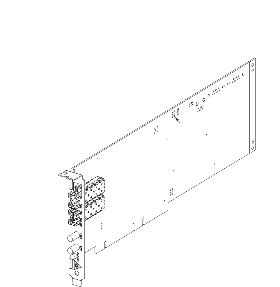
computer program. A SDR PCIx Host Card is shown in Figure 1.
Figure 1. SDR PCIx Host Card
Software Defined Radio (SDR) allows a single device to adapt to different communications
environments and systems by selecting the most appropriate protocol and frequency needed for
a link. One device may work with a wireless local area network protocol in the city, and then be
reconfigured to work with terrestrial and satellite protocols to deliver broadband applications to
rural and remote areas.
SDR works much like desktop computing, where a single hardware platform carries out many
functions based on the software applications loaded. SDR uses software to perform radio-signal
processing functions instead of using resistors, capacitors, feedback loops, or application-
specific integrated circuits.
19307-A
PIN
1

ADCP-75-198 • Issue 1 • October 2005
Page 5
© 2005, ADC Telecommunications, Inc.
The SDR PCIx host card is installed in a server and cabled to the LRCS remote (radio head)
units and the GPS receiver. Power is provided by the server with configuration and software
management through the server communications interface. Communications with the network
is through the server and associated hardware and software.
1.1 Operating Conditions
The host card is designed to operate in any server that operates in this temperature range (+32°F
to +122°F (0°C to +50°C).
2 SDR CARD INSTALLATION
2.1 Power Down the Server
1. Back up the server data.
2. Shut down the operating system as directed by the operating system documentation.
3. If the server is installed in a rack, locate the server.
4. Some servers may have a standby mode, if your server has a standby mode, press the
Power On/Standby button to place the server in standby mode. When the server activates
standby power mode, the system power LED should indicate the change to standby mode.
5. Disconnect the power cords. Server is now without power.
2.2 Extend Server from the Rack
Loosen the thumbscrews that secure the server faceplate to the front of the rack. Extend the
server on the rack rails until the server rail-release latches engage.
2.3 Remove Access Panel
Warning: To reduce the risk of personal injury, electric shock, or damage to the equipment,
remove the power cord to remove power from the server. The front panel Power On switch may
not completely shut off system power. Portions of the power supply and some internal circuitry
may remain active until AC power is removed.
Warning: To reduce the risk of personal injury or equipment damage, be sure that the rack is
adequately stabilized before extending a component from the rack.
Warning: To reduce the risk of personal injury, be careful when pressing the server rail-release
latches and sliding server into the rack. The sliding rails could pinch your fingers.
Warning: To reduce the risk of personal injury from hot surfaces, allow the drives and the
internal system components to cool before touching them.
ADCP-75-198 • Issue 1 • October 2005
Page 6
© 2005, ADC Telecommunications, Inc.
Lift up on the hood latch handle and remove the access panel.
2.4 Remove PCI Riser Cage
1. If necessary, disconnect any internal or external cables connected to all expansion boards.
2. Lift the PCI riser cage thumbscrews and turn them counter-clockwise.
3. Remove the PCI riser cage.
2.5 Remove Expansion Slot Cover
Most servers contain a PCI-X backplane that is part of the PCI riser cage. The PCI backplane
normally provides hot-plug capability to two expansion slots and a third non-hot-plug expansion
slot.
SDR
PCIx Host card is installed in the non-hot-plug PCI-X expansion slot that meets the
specification; 64-bit/133-MHz 3.3V. Determine which slot the
SDR
card is to be installed in and
remove the expansion slot cover.
2.6 Installing a SDR PCIx Host Card
1. Slip on an Electro-Static Discharge (ESD) wrist strap and connect the ground wire to an
earth ground source. Wear the ESD wrist strap while completing the SDR PCIx Host Card
installation procedure.
2. Unlock the PCI retaining clip.
3. Install the card.
4. Lock the PCI retaining clip.
5. Power, network interface, and communications to the card are supplied through the card
edge connector.
Caution: Do not operate the server for long periods without the access panel. Operating the
server without the access panel results in improper airflow and improper cooling that can lead
to thermal damage.
Caution: To prevent damage to the server or expansion boards, power down the server and
remove all AC or DC power cords before removing or installing the PCI riser cage.
Caution: To prevent improper cooling and thermal damage, do not operate the server unless all
PCI slots have either an expansion slot cover or an expansion board installed.
Caution: Electronic modules can be damaged by electrostatic discharge (ESD). To prevent this,
take the following precautions:
• Wear an anti-static-discharge wrist strap while handling modules.
• Place modules in anti-static packing material when transporting or storing them.

ADCP-75-198 • Issue 1 • October 2005
Page 7
© 2005, ADC Telecommunications, Inc.
2.7 Install PCI Riser Cage
1. Align the PCI riser cage with the chassis and slide it into place.
2. Tighten the screws to secure the PCI riser cage.
2.8 Install Access Panel
1. Place the access panel on top of the server with the hood latch open.
2. Push down on the hood latch. The access panel slides to a closed position.
2.9 Slide Server Into Rack
After performing the SDR PCIx Host card installation procedure, slide server back into the rack:
1. Press the server rail-release latches and slide the server fully into rack.
2. Secure the server by tightening the thumbscrews.
3 SDR PCIx HOST CARD CABLING
3.1 Optical and Electrical Connections
Optical and electrical connections with the remote unit and GPS are supported by four optical
and two electrical ports. The electrical interface to the GPS is through coaxial cable connections
using two type SubMiniature version A (SMA) female connectors. Single-mode fiber provides
the optical connection between the SDR PCIx Host Card and Remote Units. The forward and
reverse ports provide the optical communication channel in a non-diversity system. The REV
DIV port provides receive optics for a diversity system. Each optical port uses a small form
factor LC-type optical transceiver. Modular optical transceivers are field replaceable and
available separately.
3.2 Coax Cabling
3.2.1 Coaxial Cable Requirements
SDR
PCIx Host card is equipped with
SMA
-type female 50-Ohm connectors for connecting the
timing input/output signals from the GPS unit. High performance, flexible, low loss 50-ohm
coaxial communications cable (RG316 or equivalent) should be used for all coaxial connections.
RF coaxial cable connectors are N-type (female) 50 Ohms input/output impedance.
Caution: To prevent damage to the server or expansion boards, power down the server and
remove all AC power cords before removing or installing the PCI riser cage.
ADCP-75-198 • Issue 1 • October 2005
Page 8
© 2005, ADC Telecommunications, Inc.
3.2.2 Coaxial Cable Connections
The RF interface between SDR PCIx Host card and the GPS is supported through a pair of type
SMA female connectors mounted on the host card front panel. One connector provides the
coaxial cable connection for the REF (10 MHz sine wave) signal. The other connector provides
the coaxial cable connection for the PPS (1 pulse per second) signal. Use the following
procedure to install the coaxial cables and connect them to the host card:
1. Obtain the required lengths of high performance, flexible, low loss 50-ohm coaxial
communications cable (RG316 or equivalent) for all coaxial connections.
2. Route the timing input/output coaxial cables (if not already routed) between the SDR PCIx
Host card and the GPS interface device (per system design) and cut to the required length.
Allow sufficient slack for dressing and organizing cables at the SDR PCIx Host card.
3. Terminate each cable end with the appropriate male connector following the connector
supplier's recommendations.
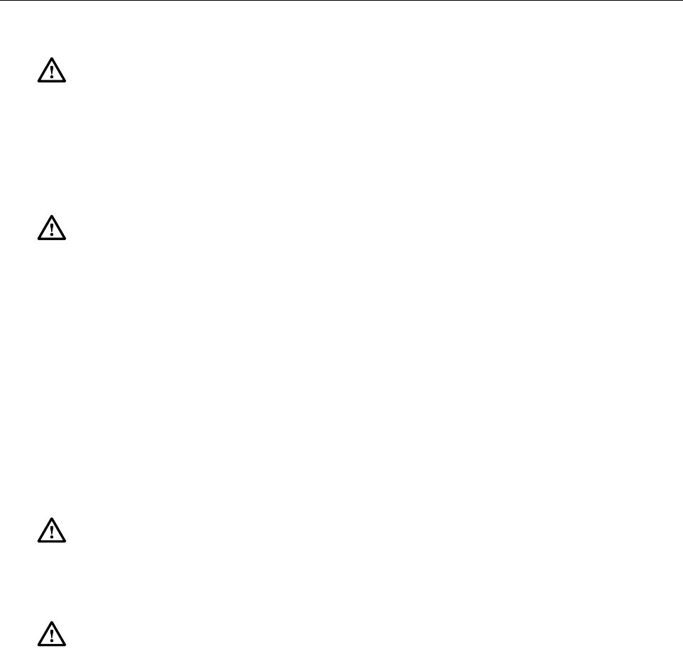
4. Connect the cables to the connectors on the SDR PCIx Host card as shown in Figure 2.
Figure 2. Coax Connectors
5. Dress and secure cables at the SDR PCIx Host card per standard industry practice.
6. Connect the coax cables to GPS receiver as specified in instructions provided with that unit.
19311-A
COAX
CONNECTORS
(TO GPS)

ADCP-75-198 • Issue 1 • October 2005
Page 9
© 2005, ADC Telecommunications, Inc.
3.3 Optical Cabling
3.3.1 Optical Options and Requirements
Each SDR PCIx Host Card and its associated remote (radio head) unit is connected over a pair of
optical fibers. One fiber transports the forward path optical signal and the other fiber transports the
reverse path optical signal. When diversity is used a third fiber is connected to the REV DIV port. 9/
125 single-mode optical fiber is used for the optical transport connection. With 9/125 single-mode
fiber, the optical path may be up to 10 kilometers in length. Optical fibers must be terminated with
duplex LC connectors for connection with the SDR card. Remote unit has SC connectors.
The maximum length of the optical links is dependent on the loss specifications of the optical
fiber and the losses imposed by the various connectors and splices. The system provides an
optical budget of 20dB (typical) when used with 9/125 single-mode fiber.
Whenever possible, use conduit or a guideway to route optical fibers between the SDR PCIx
Host card and the remote (radio head) unit. Avoid routing optical fibers through ladder type
cable racks or troughs that do not provide sufficient support to limit bending or prevent
accidental damage. Tie-wrapping is not recommended as a means of securing fiber optic cables.
Provide sufficient slack at each unit for connecting each fiber to the required port. Fibers may be
pre-terminated or terminated on-site using field-installable LC type connectors.
3.3.2 Optical Connections
The optical interface between the SDR PCIx Host card and the remote (radio head) unit is
supported by two optical ports. Each of the SDR PCIx Host card optical ports provides a duplex
LC-type optical transceiver which is mounted on the SDR PCIx Host card front. The remote
(radio head) unit has SC connectors.
The FWD and REV ports provide forward and reverse optical communications channels in a
non-diversity system. The REV DIV port provides receive optics for a diversity system See
Table 1 for transceiver port designations. See Figure 3 for port designations.
Note: To insure that all optical connectors and transceivers remain dust-free during
installation, leave all dust caps and dust protectors in place until directed to remove them
for connection.
Table 1. Transceiver Port Designations
DESIGNATION DIRECTION REMARKS
FWD Output Forward path (downlink) signal.
REV Input Reverse path (uplink) signal.
TEST Not used
REV DIV Input Receive optics.
ADCP-75-198 • Issue 1 • October 2005
Page 10
© 2005, ADC Telecommunications, Inc.
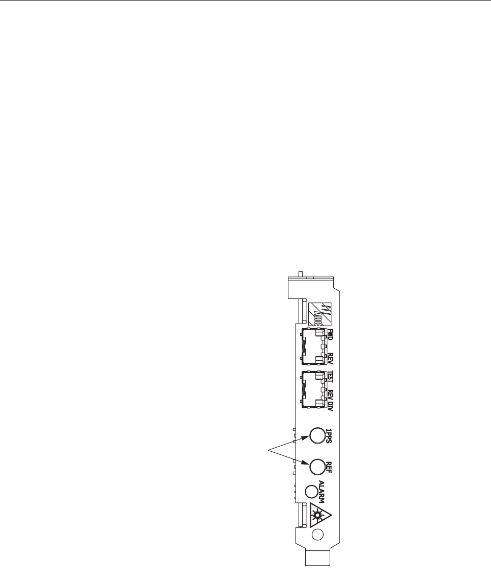
Figure 3. Optical Ports (Transceiver Sockets)
Use the following procedure to install the forward and reverse path optical fibers and to connect
them to the SDR PCIx Host card:
1. Obtain the required lengths of single-mode fiber optic cable.
2. Route the fiber optic cable between the
SDR
PCIx Host card and the remote (radio head)
unit (if not already routed) and cut to required length. Allow sufficient slack for dressing and
organizing the cables at each unit. Maintain a minimum bend radius of 2 inches (50 mm).
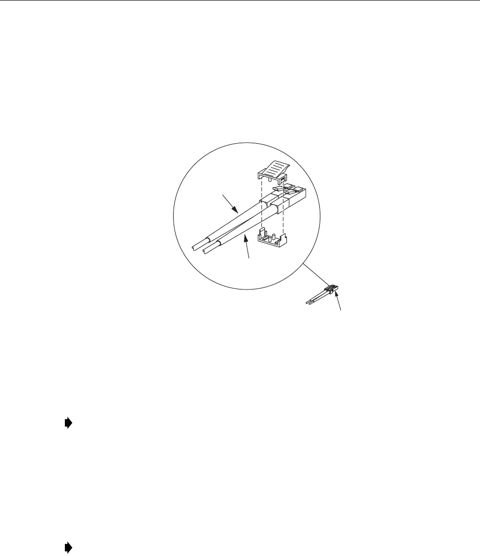
3. Terminate each optical fiber with a field-installable LC type fiber optic connector as
shown in Figure 4. Follow the instructions provided by the connector manufacturer for
installing the connector.
Danger: This equipment uses a Class 1 Laser according to FDA/CDRH rules. Laser radiation
can seriously damage the retina of the eye. Do not look into the ends of any optical fiber. Do not
look directly into the optical transceiver of any digital unit or exposure to laser radiation may
result. An optical power meter should be used to verify active fibers. A protective cap or hood
MUST be immediately placed over any radiating transceiver or optical fiber connector to avoid
the potential of dangerous amounts of radiation exposure. This practice also prevents dirt
particles from entering the transceiver or connector.
Note:
Maximum path length for 9/125 single-mode fiber optical fiber is 10 km (32,808 ft.).
19309-A
TRANSCEIVER
SOCKETS
ADCP-75-198 • Issue 1 • October 2005
Page 11
© 2005, ADC Telecommunications, Inc.
4. Test each fiber for optical loss.
5. Designate one of the fibers as the forward path fiber and the other as the reverse path fiber
and label both ends of each fiber with the path designation.
6. Use the plastic joiner provided with the LC connectors to join the SDR PCIx Host card
forward and reverse path connectors together (see Figure 4). Make sure the forward path
and reverse path connectors are oriented as shown.
Figure 4. Terminate Optical Fiber
7. Remove dust caps from the optical fiber connectors and the primary optical transceiver.
8. Clean each connector (follow connector supplier's recommendations) and then insert the
optical fiber connector pair into SDR PCIx Host card optical FWD/REV port.
9. Place the optical fibers within the cable guides provided on the cable management tray and
then dress and secure the fibers at the SDR PCIx Host card per standard industry practice.
10. Connect the forward and reverse path optical fibers to the
remote (radio head) unit
as
specified in the instructions provided with that unit.
11. Use the designation card provided to indicate the location and name of the
remote (radio
head) unit
that is connected to the SDR PCIx Host card. The designation card holder may
be attached to any convenient flat surface.
Note: Leave the dust cap in place on any unused optical transceiver.
Note: To prevent damage to the remote optical receiver, there must be at least 15dB of
attenuation at the optical receiver port.
19310-A
REVERSE PATH (RX)
CONNECTOR
FORWARD PATH (TX)
CONNECTOR
OPTICAL CONNECTOR
ASSEMBLY DETAIL
OPTICAL
CONNECTOR
ADCP-75-198 • Issue 1 • October 2005
Page 12
© 2005, ADC Telecommunications, Inc.
3.4 Modular Optical Transceiver Installation
Modular optical transceivers are available separately and may or may not be installed in the SDR
PCIx Host Card depending on the configuration ordered. If optical transceivers are factory
installed in the SDR PCIx Host Card, skip this section and proceed to
Section 3.3.2 Optical
Connections on page 9
. If optical transceivers are not factory installed, use the following
procedure to install each transceiver:
1. Slip on an ESD wrist strap and connect ground wire to an earth ground source. Wear ESD
wrist strap while completing optical transceiver installation procedure.
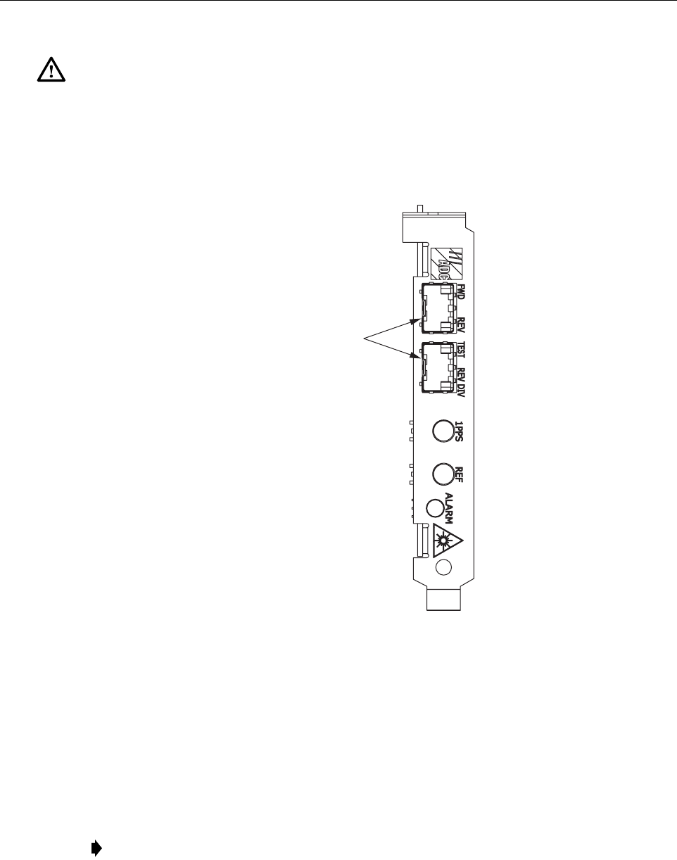
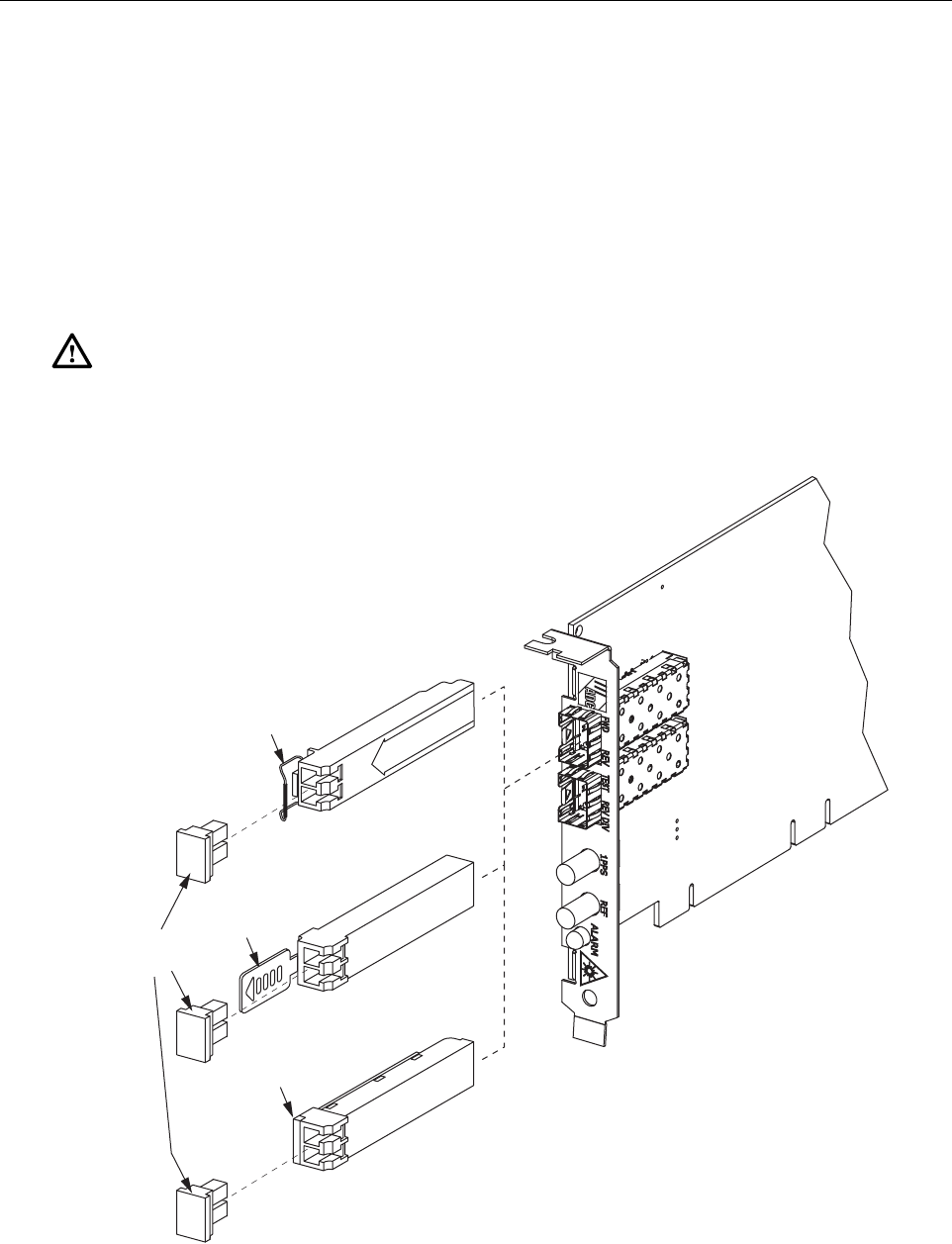
2. Locate the appropriate transceiver socket on the front of the SDR card as shown in
Figure 5 and remove the cover from the socket.
Figure 5. Optical Transceiver Installation
Warning: Electronic components can be damaged by static electrical discharge. To prevent
ESD damage, always wear an ESD wrist strap when handling electronic components.
19312-A
TYPE A
TRANSCEIVER
TYPE B
TRANSCEIVER
TYPE C
TRANSCEIVER
RELEASE
LEVER
RELEASE
TAB
RELEASE
BAR
DUST
CAPS

ADCP-75-198 • Issue 1 • October 2005
Page 13
© 2005, ADC Telecommunications, Inc.
3. Select optical transceivers shown in Figure 5.
4. Remove transceiver from anti-static packaging and orient for installation. See Figure 5.
5. Insert the optical transceiver into the socket until it locks into place.
6. Replace the optical transceiver dust cap if it was removed for installation.
7. Repeat procedure for each optical transceiver that requires installation.
4 POWERING UP THE SERVER
To power up the server, connect power cord and move the start/on button to the ON position.
5 GAIN CONFIGURATION PARAMETERS
The EMS allows the user to configure forward, reverse, and diversity path gain settings on the
Host PCIx card within the valid ranges.
5.1 Gain (Attenuation)
Gain is configured on a per channel basis and is independent for each Tx, Rx, and Rx diversity
channel. Gain ranges for forward and reverse paths are shown below:
Primary Forward Path Range: 10 to –20dB
Primary Reverse Path Range: 0 to –30dB
Secondary Reverse (Diversity) Path Range: 0 to –30dB
5.2 Wide-band Gain (Attenuation)
Wide-band Gain is set at the Remote Unit, range is 0 to –30dB in increments of 1dB.
6 OPERATION
All operation of the SDR PCIx Host card is though the software. Use software utilities to configure
new hardware in the system. For more configuration information, refer to software documentation.
6.1 Alarm LED
Under normal operation the Alarm LED is green. Alarm
indicator is
defined in
Table 2
.
Note:
A variety of optical transceivers are available, all provide the same functionality. On
the type A optical transceiver, the release lever (see
Figure 5
) must be closed for installation.

ADCP-75-198 • Issue 1 • October 2005
Page 14
© 2005, ADC Telecommunications, Inc.
7 SPECIFICATIONS
Nominal specifications for the SDR PCIx Host Card operating at 800 MHz are listed in Table 3.
Table 2. LED Indicators
COLOR STATUS
RED SDR PCIx Host card failure
YELLOW Minor alarm
GREEN Normal operation
OFF Power OFF
Note: To comply with Maximum Permissible Exposure (MPE) requirements, the
maximum composite output from the antenna cannot exceed 1000 Watts EIRP and the
antenna must be permanently installed in a fixed location that provides at least 6 meters
(20 feet) of separation from all persons.
Table 3. PCIx Host Card 800 MHz Specifications
PARAMETER SPECIFICATION REMARKS
RF Forward Path - 800 MHz System
Bandwidth
A band
B band
11 and 1.5 MHz
10 and 2.5 MHz
Frequency range
A band
B band
869–880 and 890–891.5 MHz
880–890 and 891.5–894 MHz
Out-of-band emissions
Primary
Secondary
–13 dBm per 1 MHz bandwidth
from 10 kHz to 20 GHz
–98 dBm per 100 kHz from 824
to 849 MHz
Gain of forward path
(PCIx Card to Remote primary
antenna port)
84.5 dB with 50 Watt LPA At band center, room tempera-
ture, and 0 dB attenuation setting.
Includes power amplifier.
Gain flatness
Band flatness
Channel flatness
± 2.0 dB across freq. range
± 1 dB variation across any 1.25
MHz channel
Gain variation ± 3 dB over temp and unit-to-unit
Out-of-band rejection –40 dB at > ±17.5 MHz from cen-
ter of subband
Propagation delay 6 µs Excludes fiber delay

ADCP-75-198 • Issue 1 • October 2005
Page 15
© 2005, ADC Telecommunications, Inc.
Configurable propagation
delay
Range
Step size
Up to 63 µs
0.1µs ± 100 ns
Plus standard propagation delay
Spurious
In-band self generated
Free dynamic range
–13 dBm at remote output
60 dB at 30 kHz bandwidth
Transmit peak-to-average 10 dB
Two-tone Intermodulation –55 dBc at remote output Two tones at 5 Watts each
Nominal composite RF PCIx
card signal level
10 to –20 dB Commission signaling initially at
less than max value to prevent
overpowering the LPA.
Composite RF output power
With 50 Watt LPA * 44.5 dBm (28.5 Watts) at remote
antenna port
50 Watts at LPA output
Configurable RF Output
Range
Step size
31 dB at remote unit
1 ±0.5 dB ±10% of attenuation
monotonic
Transmit path insertion loss 2.5 dB
RF Reverse Path - 800 MHz
Bandwidth
A band
B band
11 and 1.5 MHz
10 and 2.5 MHz
Frequency range
A band
B band
824–835 and 845–846.5 MHz
835–845 and 846.5–849 MHz
In band spurs (caused by an
individual out-of-band signal)
–75 dBc (1 MHz to 20 GHz
and > 10 MHz out-of-band)
–120 dBc (869 to 894 MHz)
Propagation delay 6 µs Excludes fiber delay
Configurable propagation delay
Range
Step size
Up to 63 µs
0.1µs ±1 100 ns
Plus standard propagation delay
Gain flatness
Band flatness
Channel flatness
1.5 dB across frequency range
±1 dB variation across any 1.25
MHz channel
Gain of reverse path
Overall gain
Gain variation
30 ± 2 dB at band center at room
temperature
3 dB over temperature
ALC not invoked
ALC not invoked
Out-of-band rejection –40 dB at > ±17.5 MHz from
center of subband
ALC not invoked
Table 3. PCIx Host Card 800 MHz Specifications, continued
PARAMETER SPECIFICATION REMARKS

ADCP-75-198 • Issue 1 • October 2005
Page 16
© 2005, ADC Telecommunications, Inc.
Nominal specifications for the SDR PCIx Host Card operating at 1900 MHz are listed in
Table 4
.
Spurious (in-band self gener-
ated)
–110 dBm referred to input ALC not invoked
Intermodulation –62 dBc two tones at –50 dBm
System noise figure 9 dB at mid-band ALC not invoked
Configurable RF output
Range
Step size
31 dB
1 ± 0.5 dB ± 10% of attenuation
monotonic
Blocking dynamic range 70 dB
Level limiting ALC threshold –40 dBm ± 3 dB instantaneous
Level limiting ALC range 30 dB
RF Forward and Reverse Path Modulation Accuracy
Service/Mod Type/Parameter
GSM/GMSK/rms phase error
4º
* - Per Industry Canada Section 5.3 - The rated output power of this equipment is for single carrier
operation. For situations when multiple carrier signals are present, the rating would have to be
reduced by 3.5 dB, especially where the output signal is re-radiated and can cause interference to
adjacent band users. This power reduction is to be by means of input power or gain reduction and
not by an attenuator at the output of the device.
Table 4. PCIx Host Card 1900 MHz Specifications
PARAMETER SPECIFICATION REMARKS
Optical - Host and Remote WDM
Passband 1310 nm ± 20 nm
1550 nm ± 20 nm
Forward path insertion loss
Host WDM
Remote WDM
0.7 dB
0.3 dB
Does not include connector loss
Reverse path insertion loss
Host WDM
Remote WDM
0.3 dB
0.7 dB
Does not include connector loss
Isolation > 30 dB minimum
Return loss (Reflectance) < –50 dB All input ports
RF Forward Path - 1900 MHz
System Bandwidth 20 MHz AD band, 25 MHz
DBE, BEF, and EFC bands
Table 3. PCIx Host Card 800 MHz Specifications, continued
PARAMETER SPECIFICATION REMARKS

ADCP-75-198 • Issue 1 • October 2005
Page 17
© 2005, ADC Telecommunications, Inc.
Frequency range
AD
DBE
BEF
EFC
1930 to 1950 MHz
1945 to 1970 MHz
1950 to 1975 MHz
1965 to 1990 MHz
Out-of-band emissions
Primary
Secondary (see Note 1)
–13 dBm per 1 MHz bandwidth
from 10 kHz to 20 GHz
–98 dBm per 100 kHz from 824
to 849 MHz and from 1850 to
1910 MHz
Gain of forward path
(PCIx Card to Remote primary
antenna port)
80.5 dB with 20 Watt LPA
83.5 dB with 40 Watt LPA
At band center, room tempera-
ture, and 0 dB attenuation set-
ting. Includes power amplifier.
Gain flatness
Band flatness
Channel flatness
± 1.5 dB across freq. range
± 1 dB variation across any 1.25
MHz channel
Gain variation ± 3 dB over temp and unit-to-
unit
Out-of-band rejection –40 dB at > ±17.5 MHz from
center of subband
Propagation delay 6 µs Excludes fiber delay
Configurable propagation delay
Range
Step size
Up to 63 µs
0.1µs ± 100 ns
Plus standard propagation delay
Spurious
In-band self generated
Free dynamic range
–13 dBm at remote output
60 dB at 30 kHz bandwidth
Transmit peak-to-average 10 dB
Two-tone Intermodulation –55 dBc at remote output Two tones at 5 Watts each
CDMA Intermodulation
885 kHz to 1.25 MHz
1.25 to 1.98 MHz
1.98 to 2.25 MHz
–45 dBc per 30 kHz
–8 dBm per 30 kHz
–55 dBc per 30 kHz
Absolute level
Nominal composite RF PCIx
card signal level
10 to –20 dB Commission signaling initially
at less than max value to prevent
overpowering the LPA.
Composite RF output power
With 20 Watt LPA *
With 40 Watt LPA *
40.5 dBm (11 Watts) at remote
antenna port
43.5 dBm (22.4 Watts) at remote
antenna port
20 Watts at LPA output
40 Watts at LPA output
Table 4. PCIx Host Card 1900 MHz Specifications, continued
PARAMETER SPECIFICATION REMARKS

ADCP-75-198 • Issue 1 • October 2005
Page 18
© 2005, ADC Telecommunications, Inc.
Configurable RF Output
Range
Step size
31 dB at remote unit
1 ±0.5 dB ±10% of attenuation
monotonic
Transmit path insertion loss 2.5 dB
RF Reverse Path - 1900 MHz
System Bandwidth 20 MHz AD band, 25 MHz
DBE, BEF, and EFC bands
Frequency range
AD
DBE
BEF
EFC
1850 to 1870 MHz
1865 to 1890 MHz
1870 to 1895 MHz
1885 to 1910 MHz
In band spurs (caused by an indi-
vidual out-of-band signal)
–75 dBc (1 MHz to 20 GHz
and > 10 MHz out-of-band)
–120 dBc (1930 to 1990 MHz)
–120 dBc (869 to 894 MHz) Required for dual band
Propagation delay 6 µs Excludes fiber delay
Configurable propagation delay
Range
Step size
Up to 63 µs
0.1µs ±1 100 ns
Plus standard propagation delay
Gain flatness
Band flatness
Channel flatness
1.5 dB across frequency range
±1 dB variation across any 1.25
MHz channel
Gain of reverse path
Overall gain
Gain variation
30 ± 2 dB at band center at room
temperature
3 dB over temperature
ALC not invoked
ALC not invoked
Out-of-band rejection –40 dB at > ±17.5 MHz from
center of subband
ALC not invoked
Spurious (in-band self gener-
ated)
–110 dBm referred to input ALC not invoked
Intermodulation –62 dBc two tones at –50 dBm
System noise figure 8 dB at mid-band ALC not invoked
Configurable RF output
Range
Step size
31 dB
1 ± 0.5 dB ± 10% of attenuation
monotonic
Blocking dynamic range 70 dB
Level limiting ALC threshold –40 dBm ± 3 dB instantaneous
Level limiting ALC range 30 dB
Table 4. PCIx Host Card 1900 MHz Specifications, continued
PARAMETER SPECIFICATION REMARKS

ADCP-75-198 • Issue 1 • October 2005
Page 19
© 2005, ADC Telecommunications, Inc.
Note 1: Required for co-located sites such as dual band. Otherwise, the emissions from one unit
can limit the sensitivity of the other.
RF Forward and Reverse Path
Modulation Accuracy
Service/Mod Type/Parameter
TDMA/n/4-DQSK/rms EVM
GSM/GMSK/rms phase error
EDGE/8PSK/rms EVM
EIA-97D/CDMA/rho factor
7%
4º
7%
.97%
* - Per Industry Canada Section 5.3 - The rated output power of this equipment is for single carrier
operation. For situations when multiple carrier signals are present, the rating would have to be
reduced by 3.5 dB, especially where the output signal is re-radiated and can cause interference to
adjacent band users. This power reduction is to be by means of input power or gain reduction and
not by an attenuator at the output of the device.
Table 4. PCIx Host Card 1900 MHz Specifications, continued
PARAMETER SPECIFICATION REMARKS
ADCP-75-198 • Issue 1 • October 2005
Page 20
8 CUSTOMER INFORMATION AND ASSISTANCE
© 2005, ADC Telecommunications, Inc.
All Rights Reserved
Printed in U.S.A
13944-RM
WRITE:
ADC TELECOMMUNICATIONS, INC
PO BOX 1101,
MINNEAPOLIS, MN 55440-1101, USA
ADC TELECOMMUNICATIONS (S'PORE) PTE. LTD.
100 BEACH ROAD, #18-01, SHAW TOWERS.
SINGAPORE 189702.
ADC EUROPEAN CUSTOMER SERVICE, INC
BELGICASTRAAT 2,
1930 ZAVENTEM, BELGIUM
PHONE:
EUROPE
Sales Administration: +32-2-712-65 00
Technical Assistance: +32-2-712-65 42
EUROPEAN TOLL FREE NUMBERS
UK: 0800 960236
Spain: 900 983291
France: 0800 914032
Germany: 0180 2232923
U.S.A. OR CANADA
Sales: 1-800-366-3891 Extension 73000
Technical Assistance: 1-800-366-3891
Connectivity Extension 73475
Wireless Extension 73476
ASIA/PACIFIC
Sales Administration: +65-6294-9948
Technical Assistance: +65-6393-0739
ELSEWHERE
Sales Administration: +1-952-938-8080
Technical Assistance: +1-952-917-3475
Italy: 0800 782374
PRODUCT INFORMATION AND TECHNICAL ASSISTANCE:
Contents herein are current as of the date of publication. ADC reserves the right to change the contents without prior notice.
In no event shall ADC be liable for any damages resulting from loss of data, loss of use, or loss of profits and ADC further
disclaims any and all liability for indirect, incidental, special, consequential or other similar damages. This disclaimer of
liability applies to all products, publications and services during and after the warranty period. This publication may be
verified at any time by contacting ADC's Technical Assistance Center.
euro.tac@adc.com
asiapacific.tac@adc.com
wireless.tac@adc.com
connectivity.tac@adc.com