ADC Telecommunications DVLRCS800 Digivance Long Range Coverage Solution 800 MHz Sys User Manual 75124
ADC Telecommunications Inc Digivance Long Range Coverage Solution 800 MHz Sys 75124
UserManual.wiki
>
ADC Telecommunications
>
DVLRCS800 User Manual
>
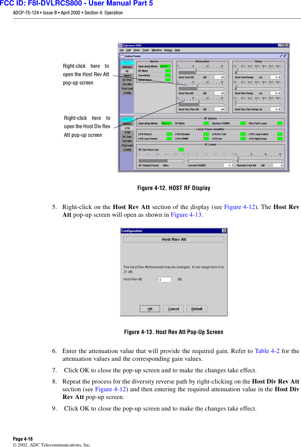
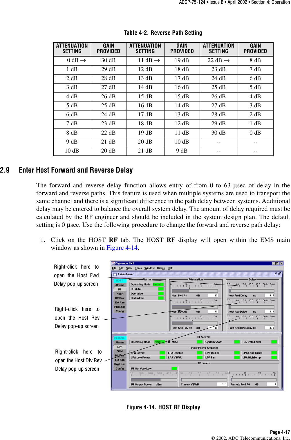
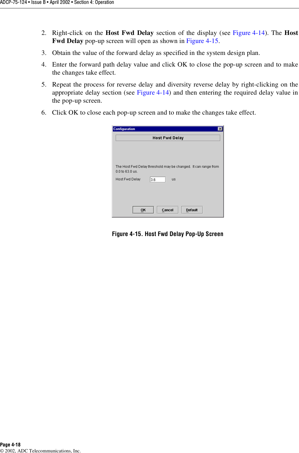
part 5
Contents
1.
part 1
2.
part 2
3.
part 3
4.
part 4
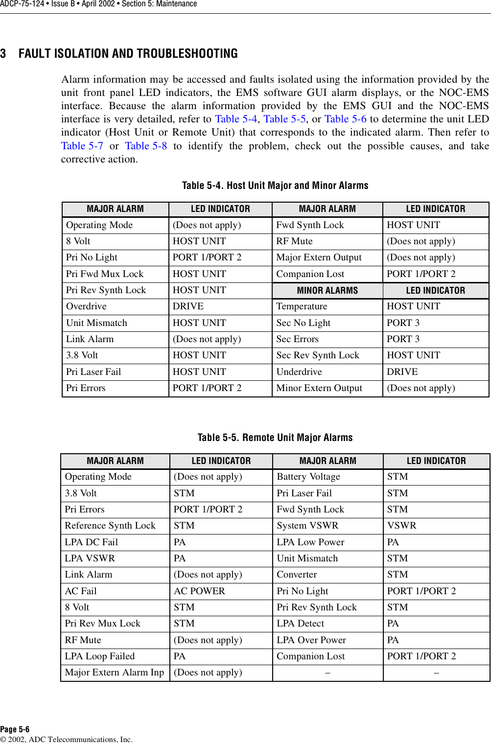
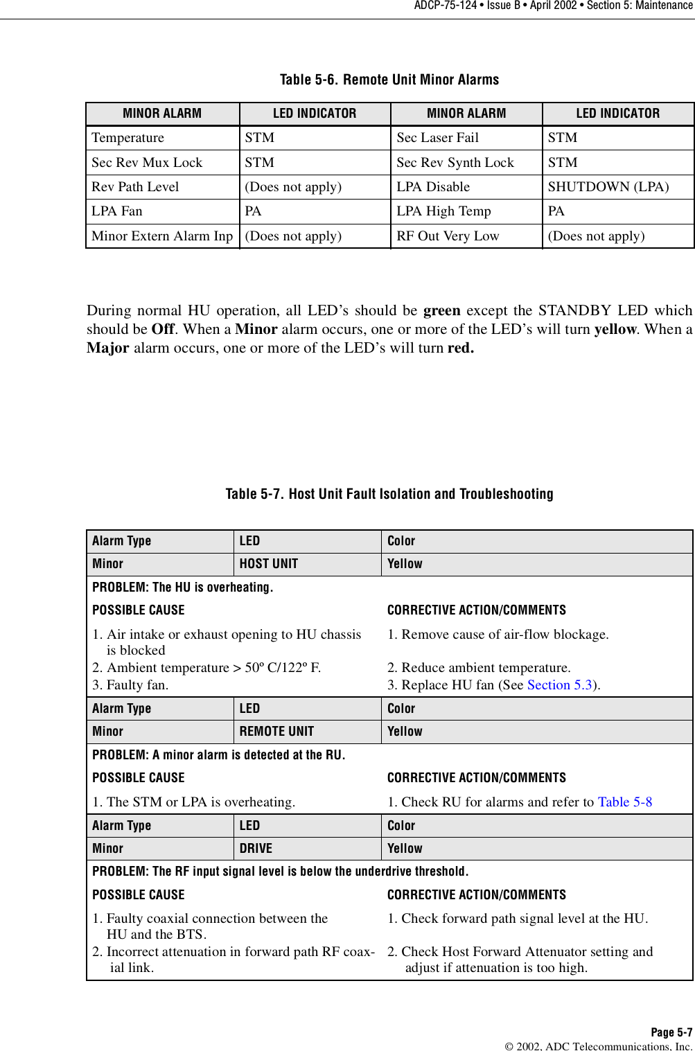
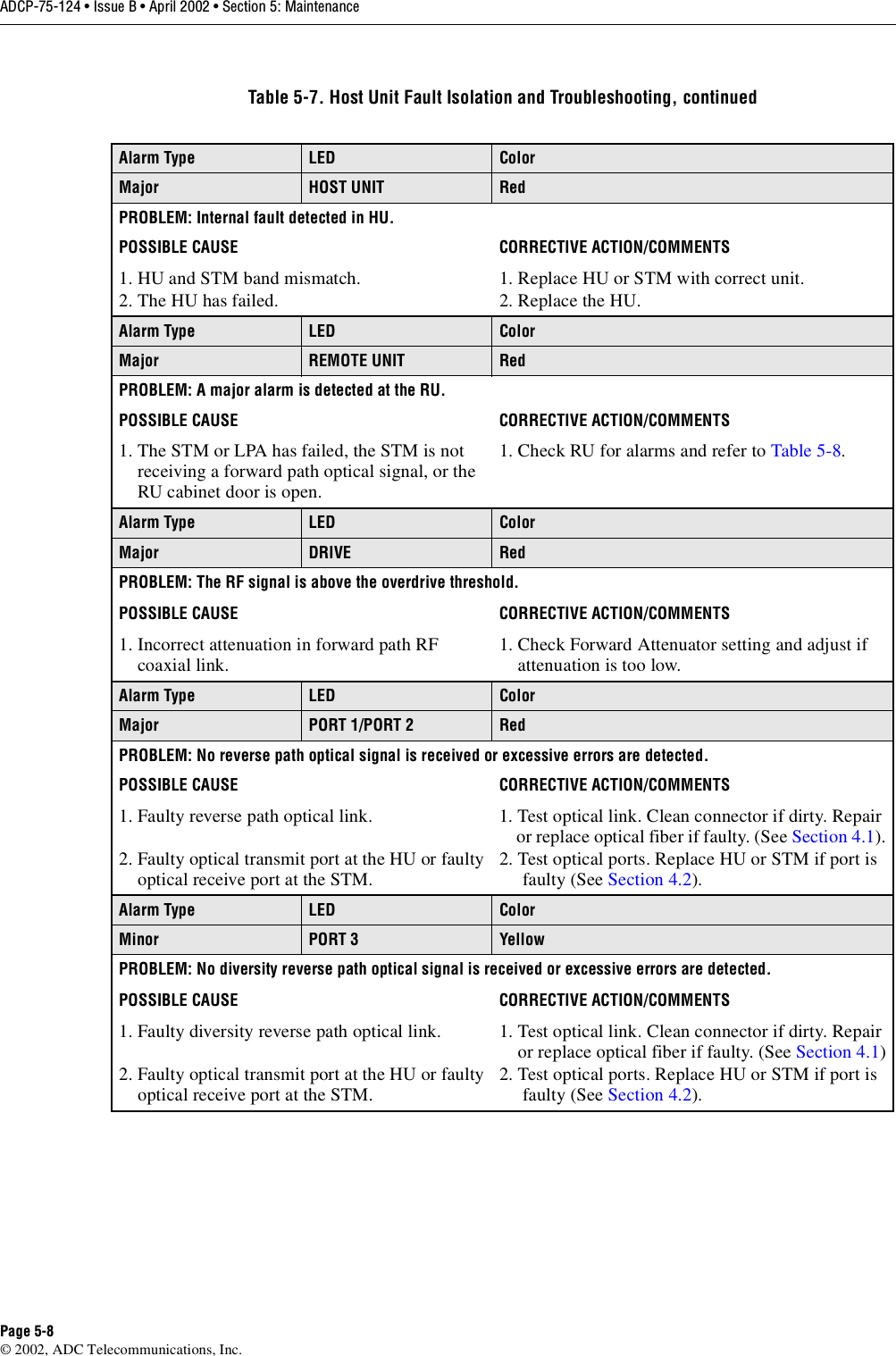
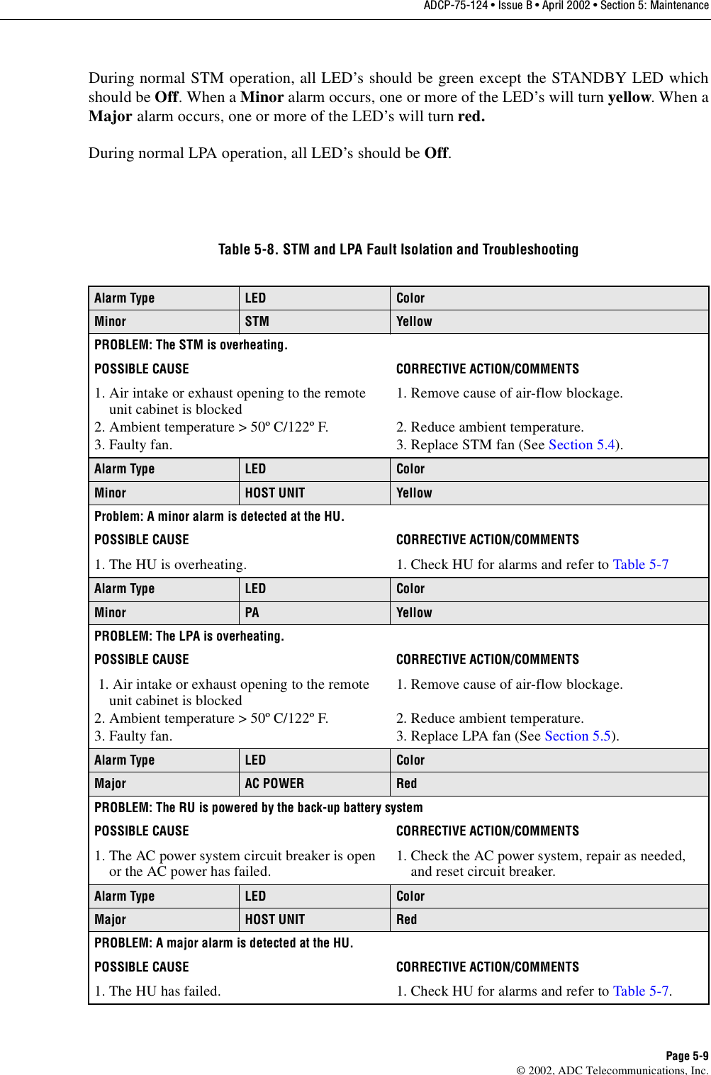
5.
part 5
part 5
Navigation menu
Upload a User Manual
Namespaces
Wiki Guide
HTML
PDF
Info
Views
User Manual
Discussion / Help
Navigation