ADC Telecommunications DWM025AA Digivance® WIMAX Remote User Manual
ADC Telecommunications Inc Digivance® WIMAX Remote
UserManual.wiki
>
ADC Telecommunications
>
DWM025AA User Manual
User manual
Navigation menu
Upload a User Manual
Namespaces
Wiki Guide
HTML
PDF
Info
Views
User Manual
Discussion / Help
Navigation
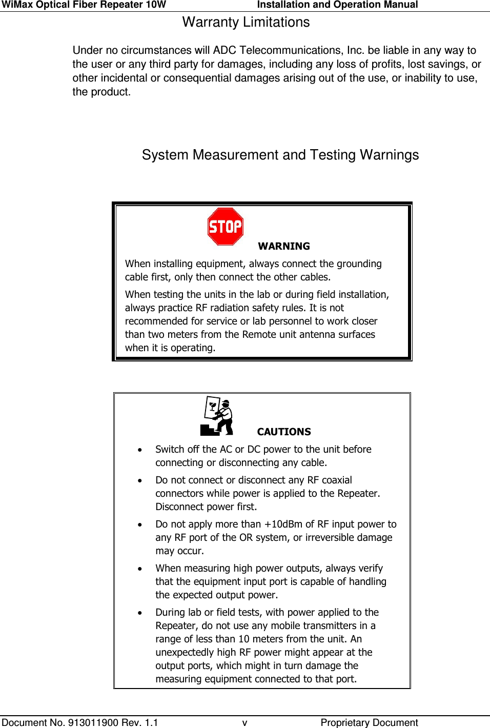
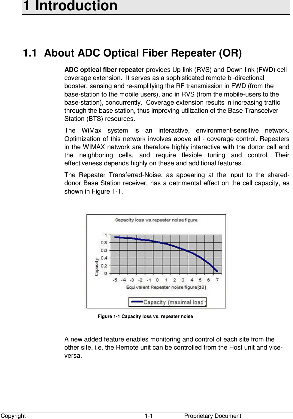
![WiMax Optical Fiber Repeater 10W Installation and Operation Manual Document No. 913011900 Rev. 1.1 Proprietary Document 3-6 3.3.1 System Setup Instructions General. The set-up of Host and Remote units FWD gains are based on maximum power considerations. This means that whenever the BTS transmits at maximum power, the Remote unit will also transmit at maximum power. The set-up of the Host and Remote units RVS gains is based on known noise level introduction into the BTS Make sure that you have a documented test results of the optical fiber link loss. Otherwise, measure it and record the results. Make sure that the fiber termination type is FC/APC. Use the following guidelines to set-up the Host and Remote units: Host Unit: • Determine the absolute maximum input power to the Host unit input connector (under the heaviest traffic conditions); let this be Pinmax [dBm]. • Set the Host unit FWD gain to 0- Pinmax [dB]. (This is in order to enter the fiber at 0 dBm). • If symmetrical link is requested, set the RVS gain to the same value as the FWD gain. • If permitted, set the RVS gain 3 dB less than the FWD gain. Remote Unit: • Set the Remote unit FWD gain to the numerical value of the maximum output power of the unit in dBm, plus the absolute value of the RF loss of the fiber (in dB). • Set the RVS gain to the same value as the FWD gain. NOTE: If reduced coverage is required, reduce the gains respectively. 3.3.2 Remote Unit FWD Gain Optimization NOTE: The RVS gain must be approximately equal to the FWD gain of the Remote unit.](https://usermanual.wiki/ADC-Telecommunications/DWM025AA/User-Guide-908000-Page-28.png)
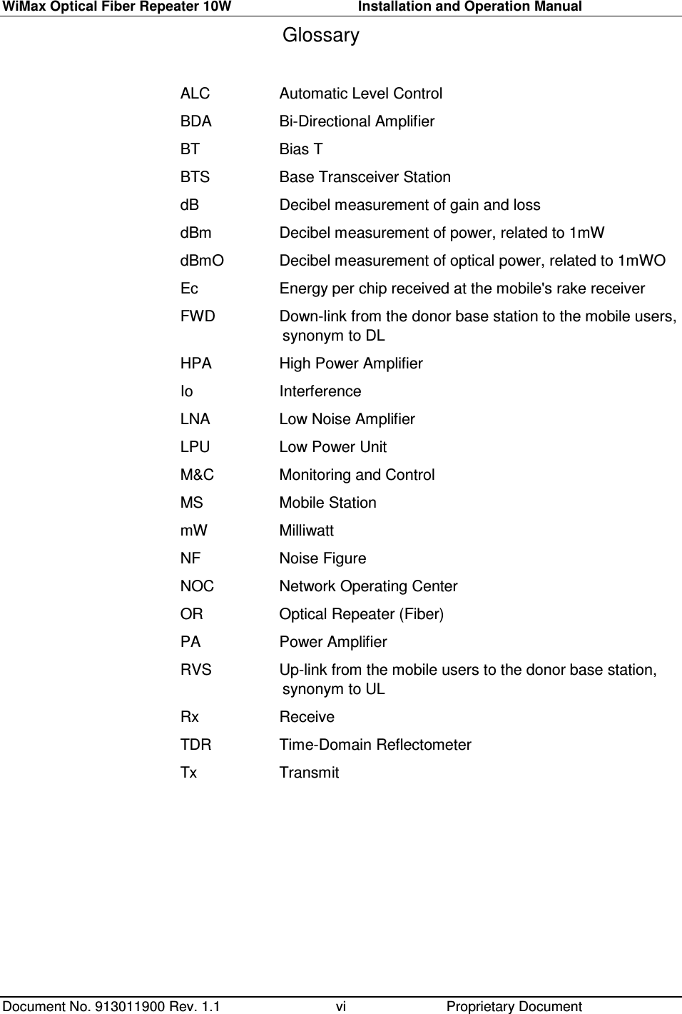
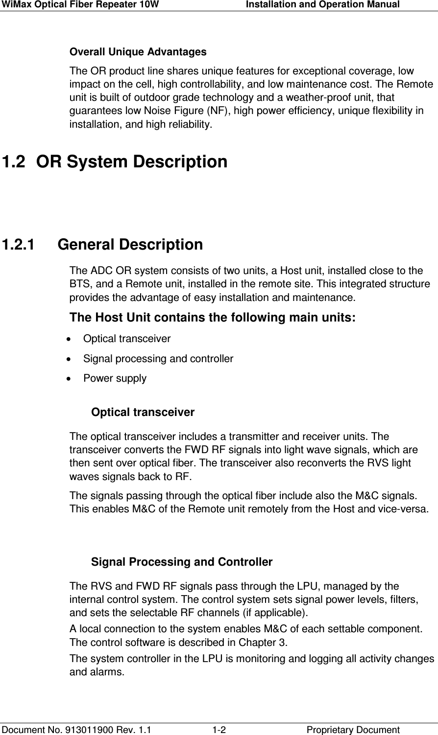
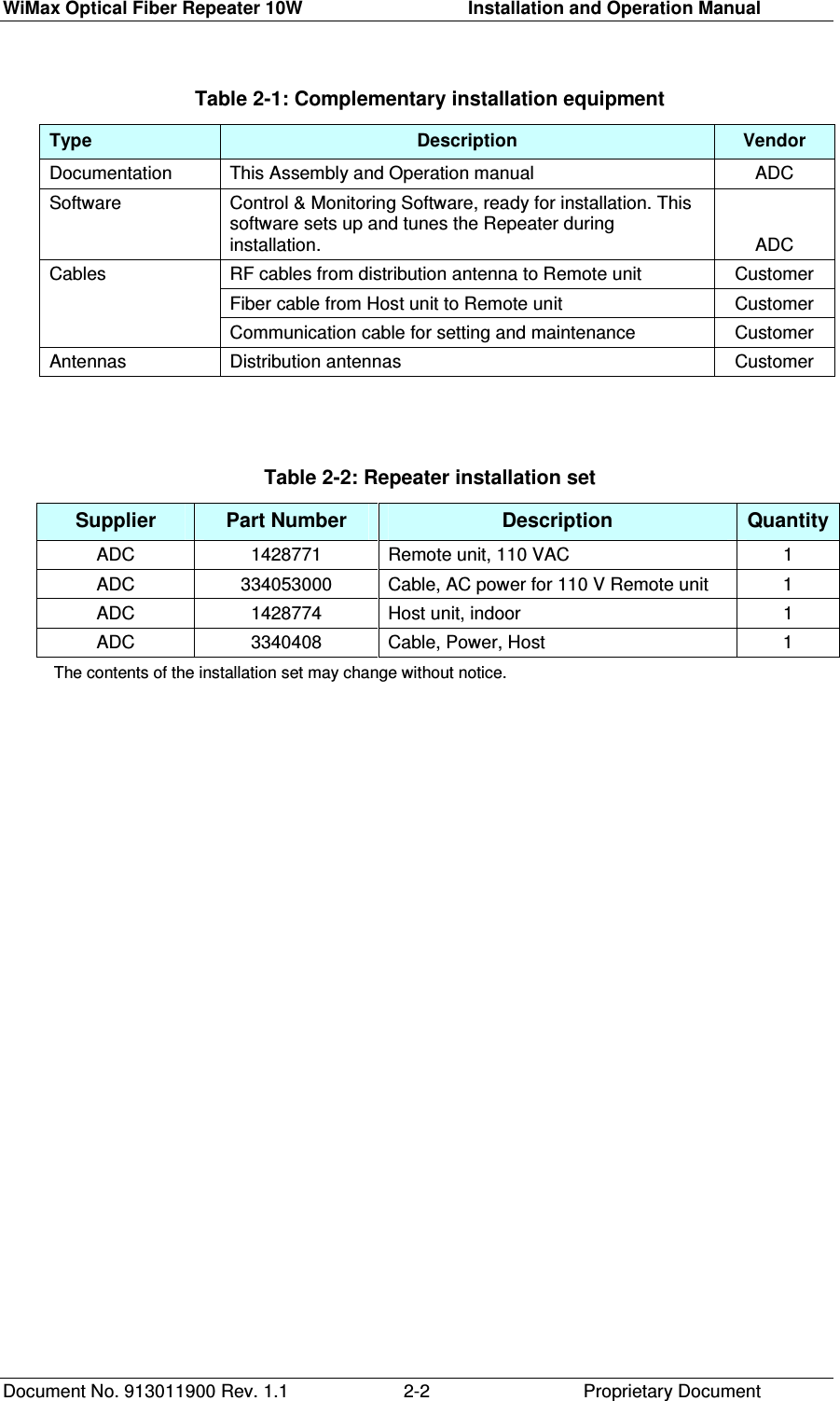
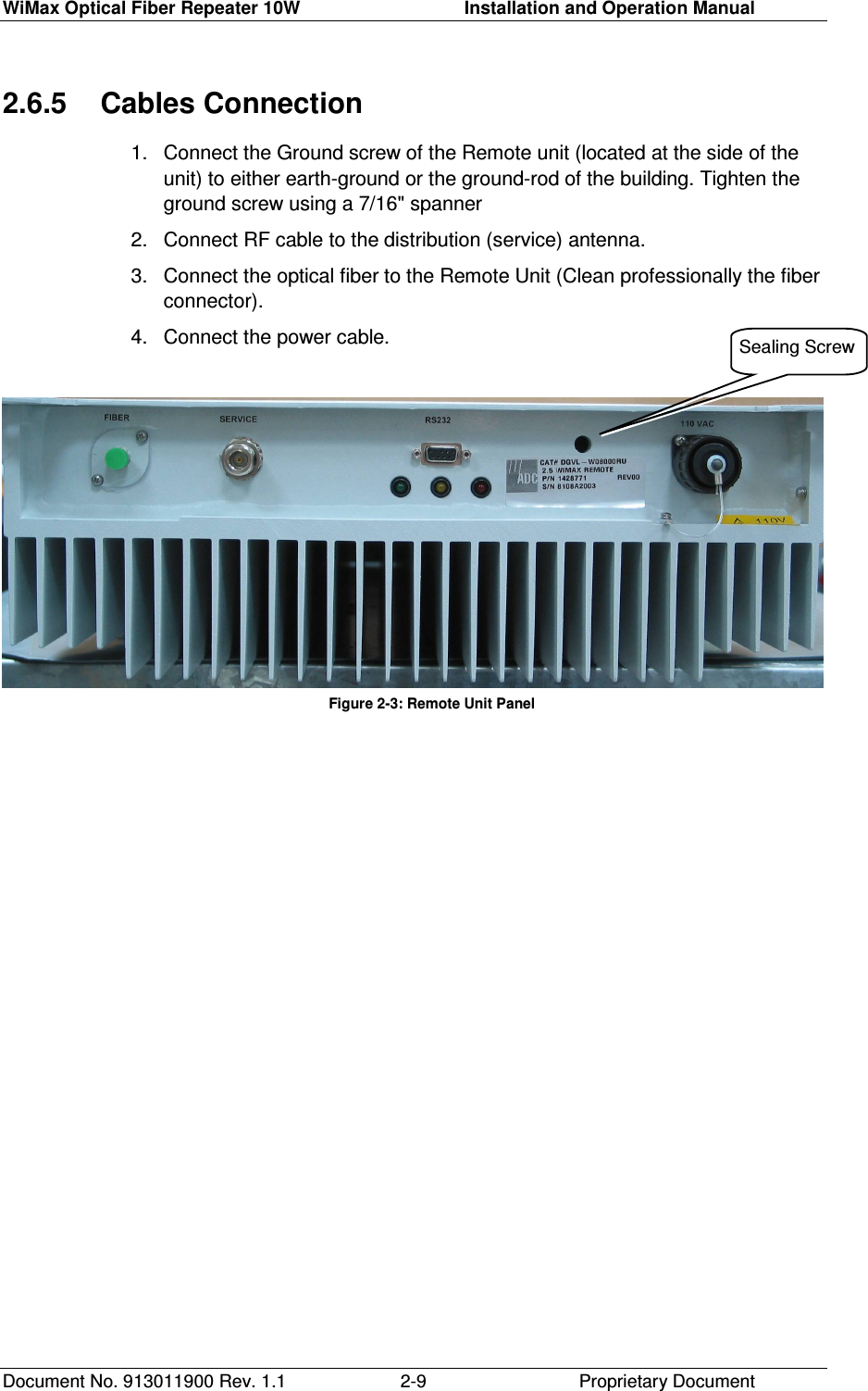
![Copyright Appendix-1 Proprietary Document APPENDIX A. SPECIFICATIONS Host Unit Specifications Parameter Specification Forward path Input Frequency Range 2640.5 – 2673.5 MHz BW 30 MHz VSWR < 1.5:1 Input Power Range -10 to 10dBm Max Rated Input Power -10 to +10 dBm Gain -15 to 15dB, nominal –10 dB Gain control step 1dB Gain flatness ± 3 dB max, over 30MHz Reverse path Output Frequency Range 2640.5 – 2673.5 MHz VSWR < 1.5:1 Max Output Power –40dBm Gain -40 to 5dB Gain control step 1dB over complete range Gain flatness ± 0.5dB max, over 10MHz Electrical Power, Mechanics, Environment Dimensions W x H x D [mm] 480 x 44 x 420 (1U) Weight 3 Kg Mounting 19” Rack Operating Temperature -5 ÷ +50 °C RF Connectors N-Type Female Optical Connectors FC/APC Humidity 85% relative Power Supply 110 VAC. (optional- -48VDC) Power Consumption < 40W](https://usermanual.wiki/ADC-Telecommunications/DWM025AA/User-Guide-908000-Page-35.png)
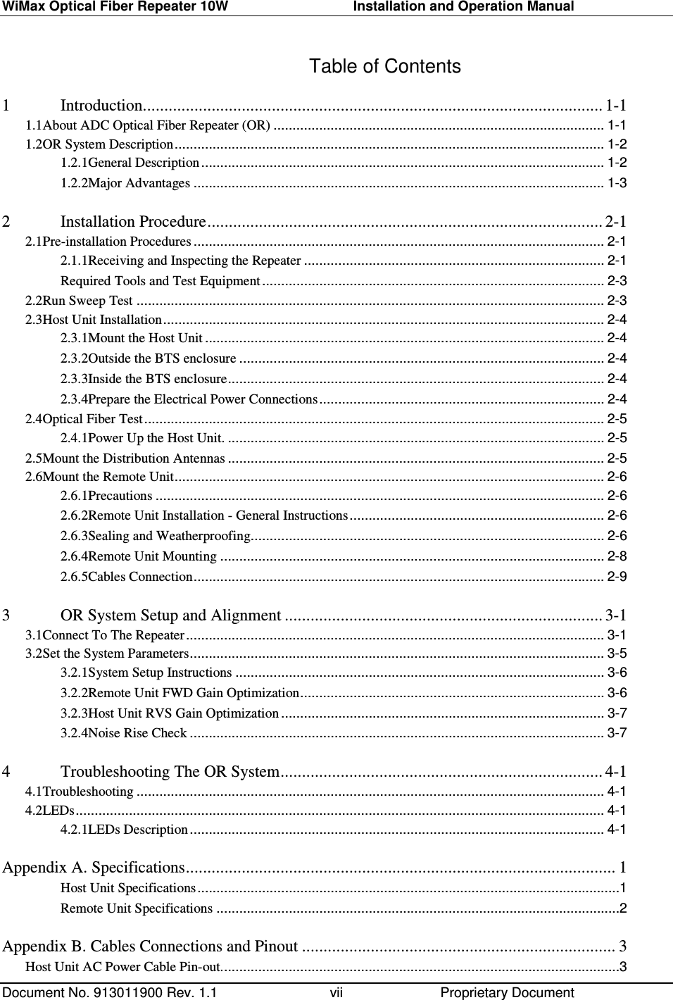
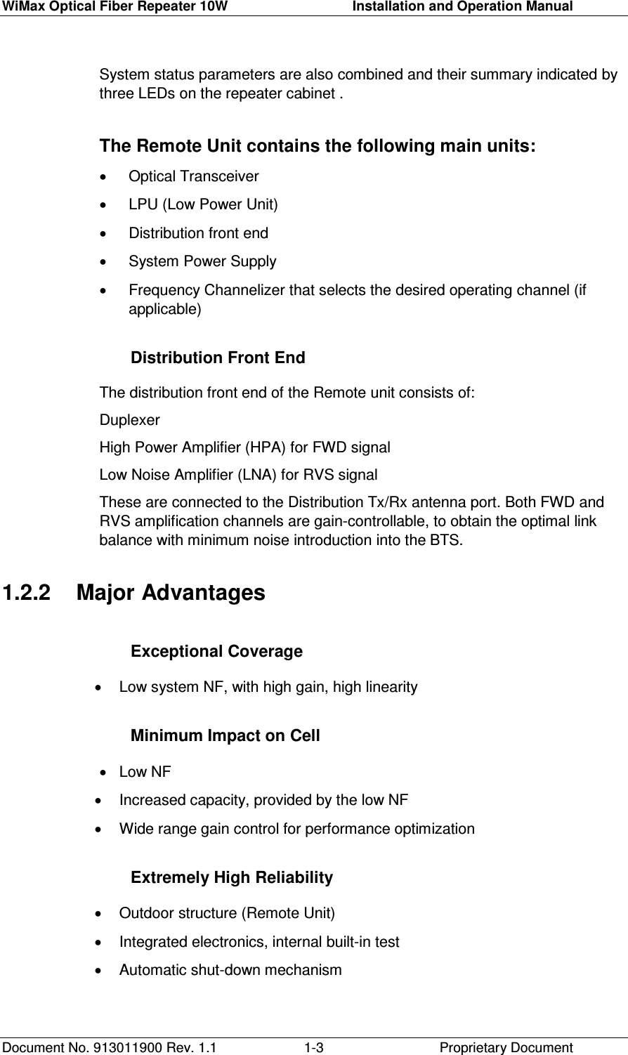
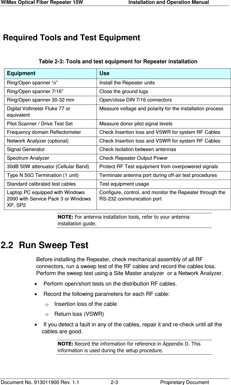
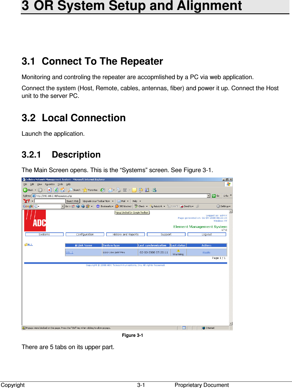
![WiMax Optical Fiber Repeater 10W Installation and Operation Manual Copyright Proprietary Document 2 Remote Unit Specifications Parameter Specification Forward path Output Frequency Range 2640.5 – 2673.5 MHz BW 30 MHz VSWR <1.5:1 Max Output Power 10W Gain 30 to 70dB, nominal 50 dB Gain control step 1dB Gain flatness ± 3 dB max, over 30MHz Reverse path Input Frequency Range 2640.5 – 2673.5 MHz VSWR <1.5:1 Noise Figure <5dB Gain 30 to 60dB Gain control step 1dB over complete range Gain flatness ±-0.5dB max, over 10MHz Electrical Power, Mechanics, Environment Dimensions W x H x D [mm] 659x424x137 Weight 25 Kg Mounting Wall RF Connectors N-Type Female Optical Connectors FC/APC Operating Temperature -33 ÷ +55 °C Humidity 85% relative Power Supply 110VAC to 230VAC Power Consumption < 270W System Specification Local Management GUI application through RS-232 port Monitors / Controls Operation Frequency, Gain, PA Mute Alarms VSWR, Synthesizer Loss of Lock, PA Fiber Link Wavelength Single Mode, 1310/1550nm Supported Fiber Length Max. 10 km Absolute Delay Max. 5µsec, excluding fiber delay](https://usermanual.wiki/ADC-Telecommunications/DWM025AA/User-Guide-908000-Page-36.png)