ADC Telecommunications F0851-111 FSN-2525-1-TDD User Manual 77044p9
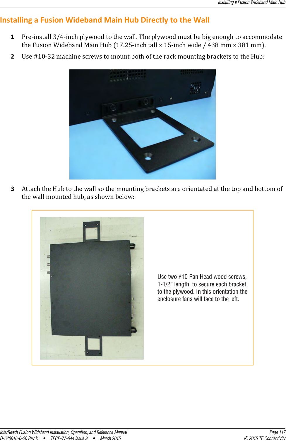
ADC Telecommunications Inc. FSN-2525-1-TDD 77044p9
UserManual.wiki
>
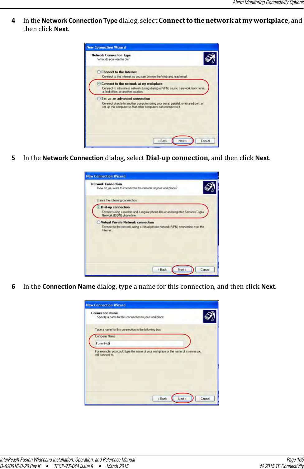
ADC Telecommunications
>
F0851 111 User Manual
User Manual
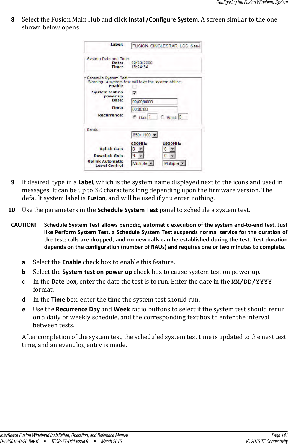
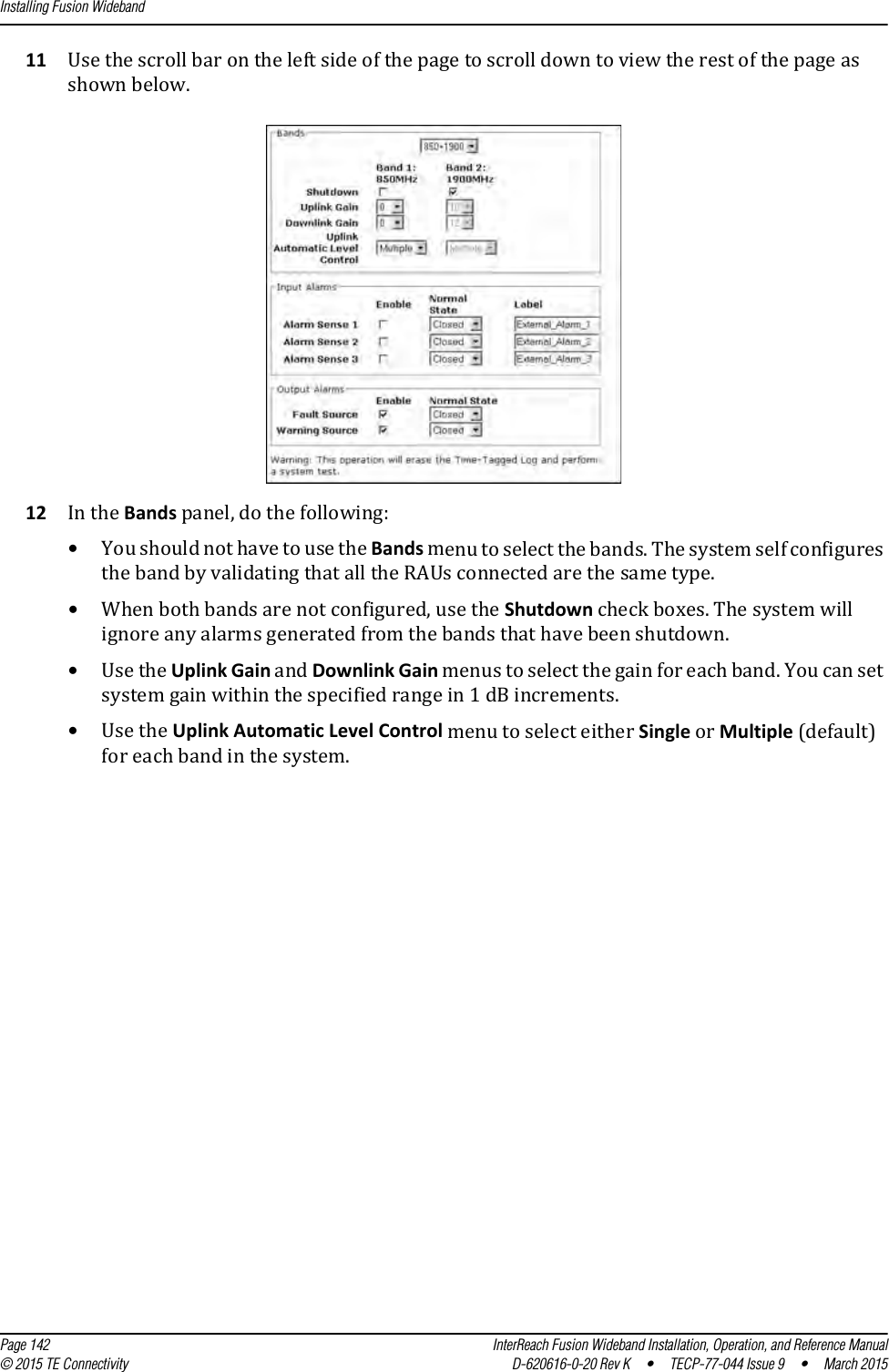
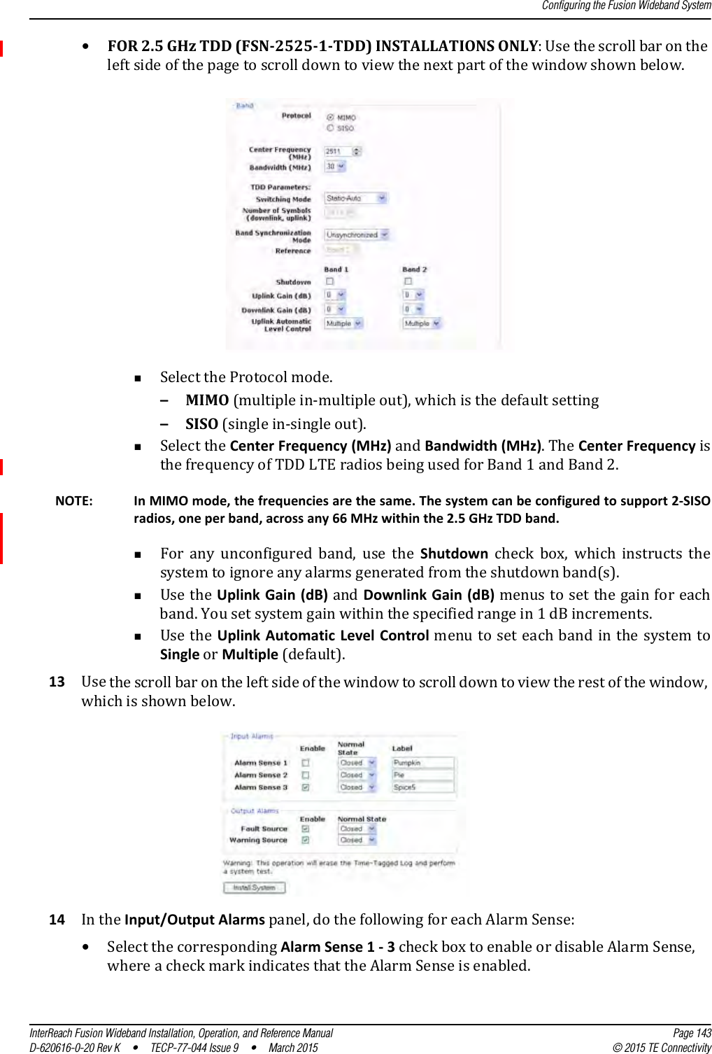
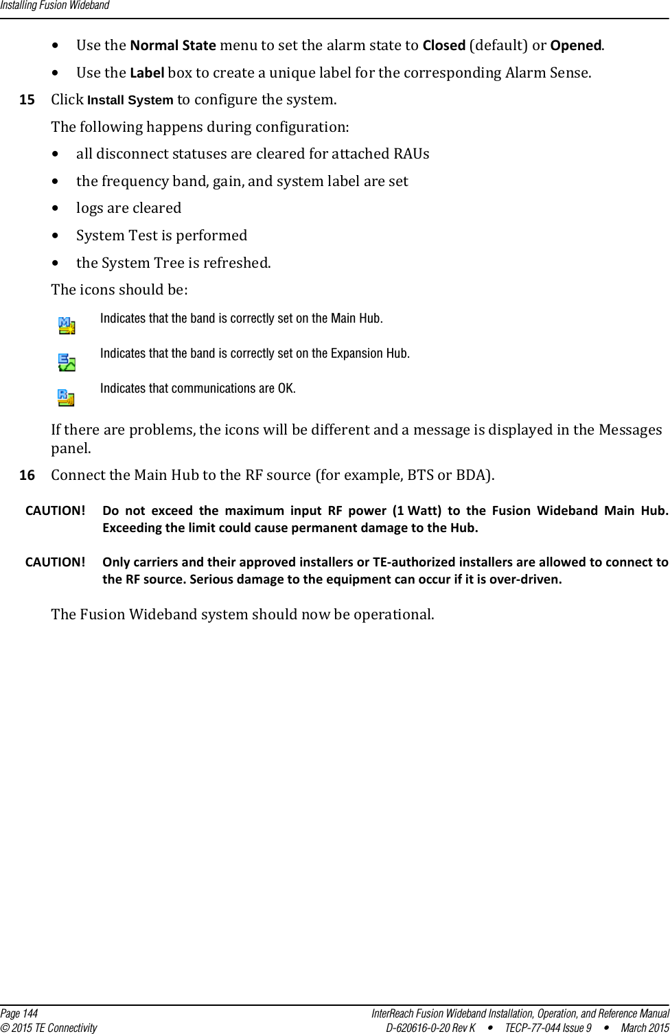
Navigation menu
Upload a User Manual
Namespaces
Wiki Guide
HTML
PDF
Info
Views
User Manual
Discussion / Help
Navigation
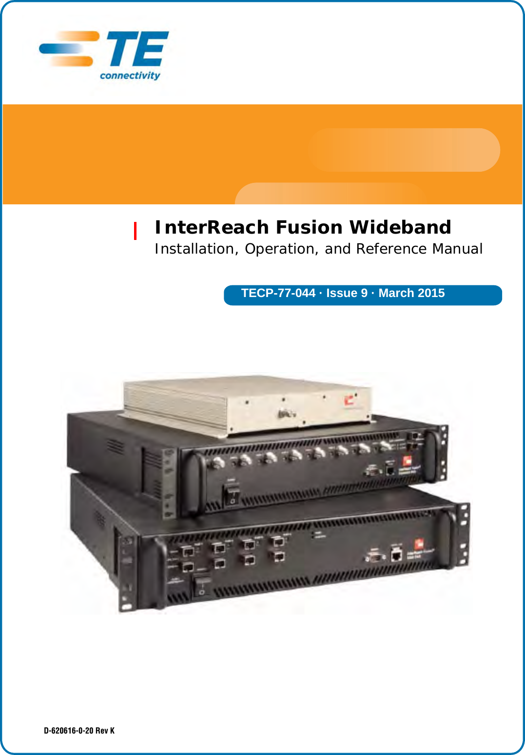
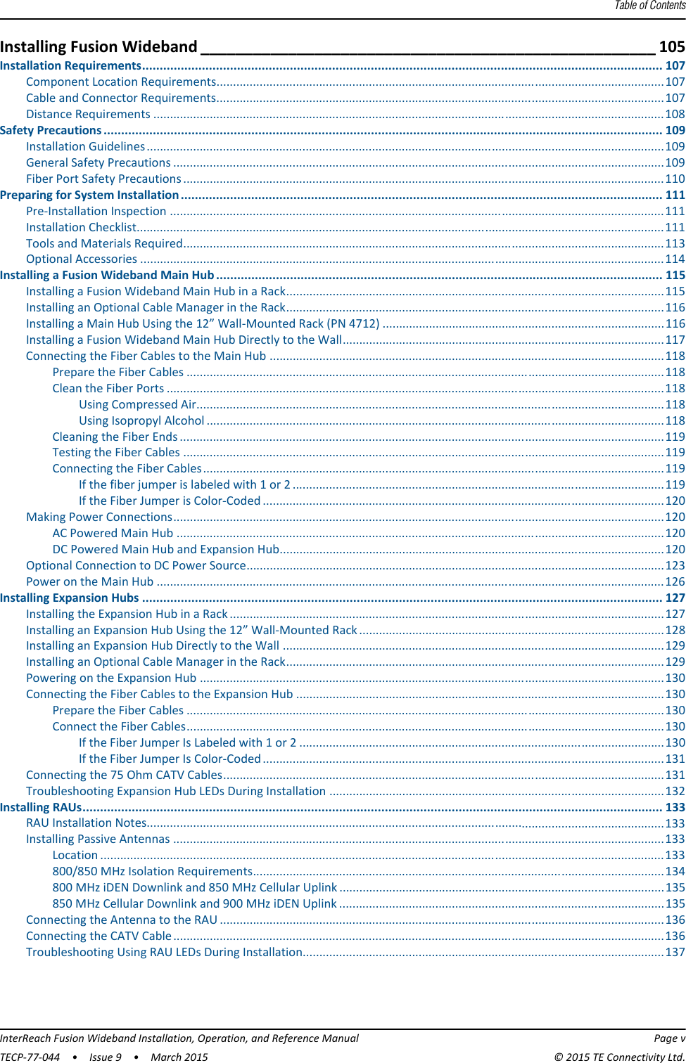

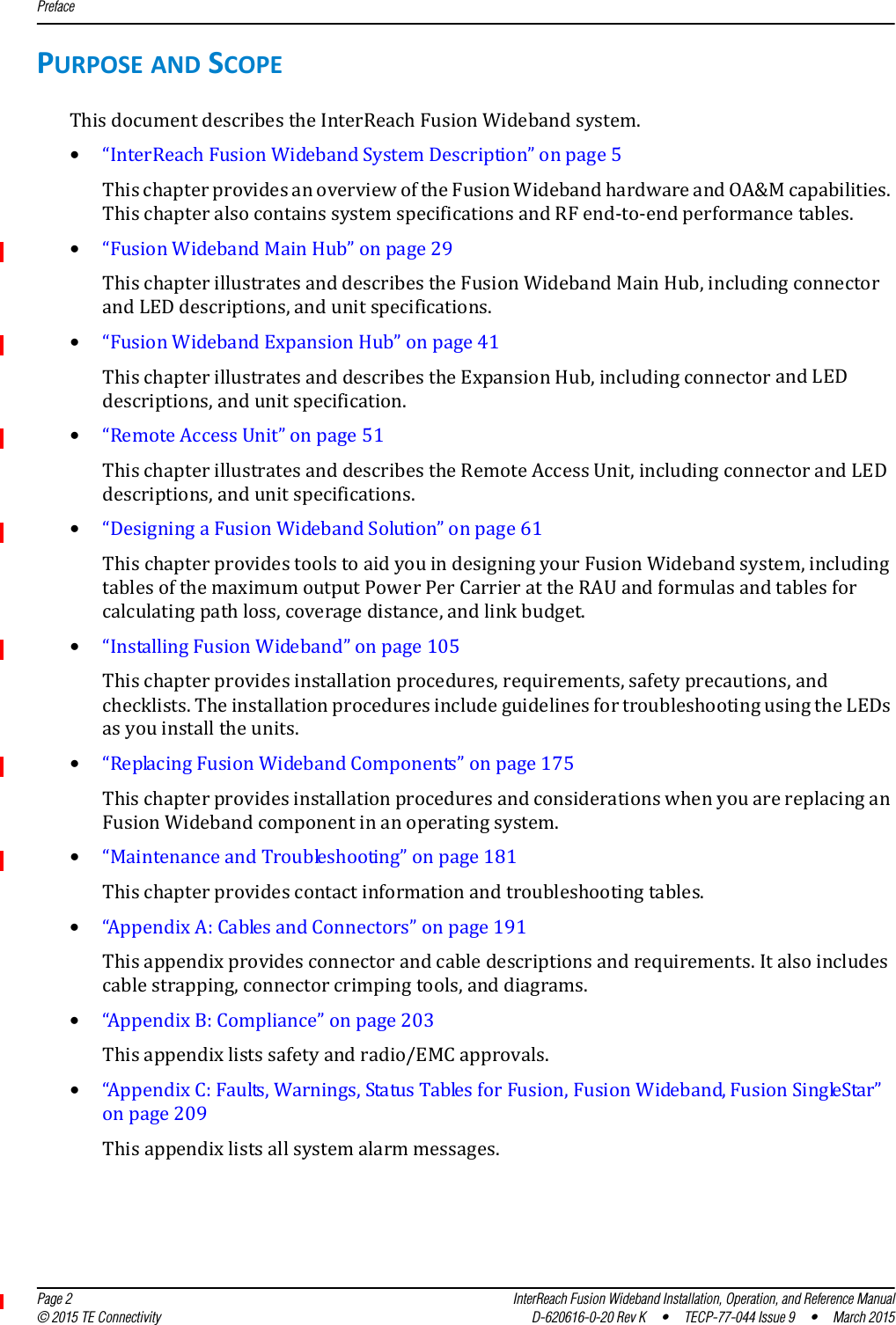
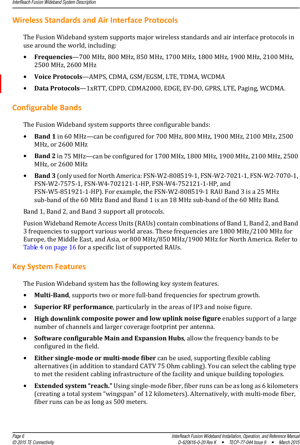

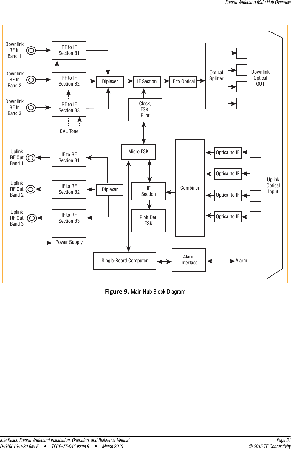
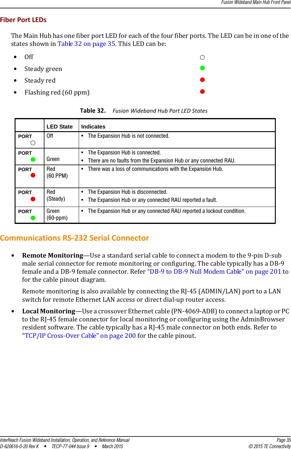
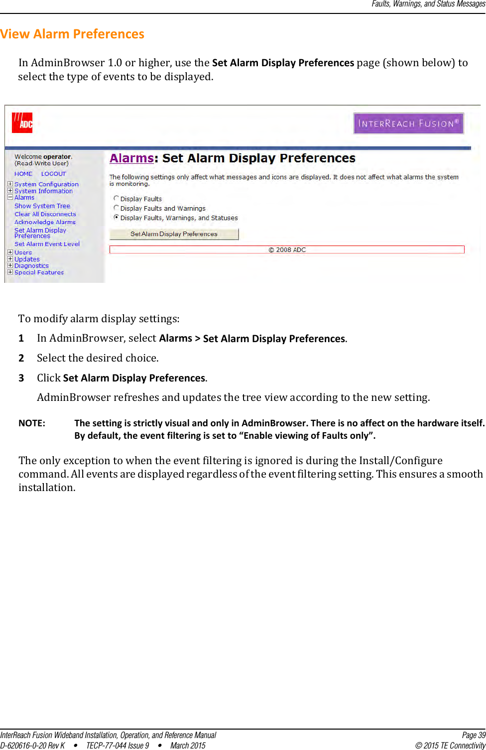

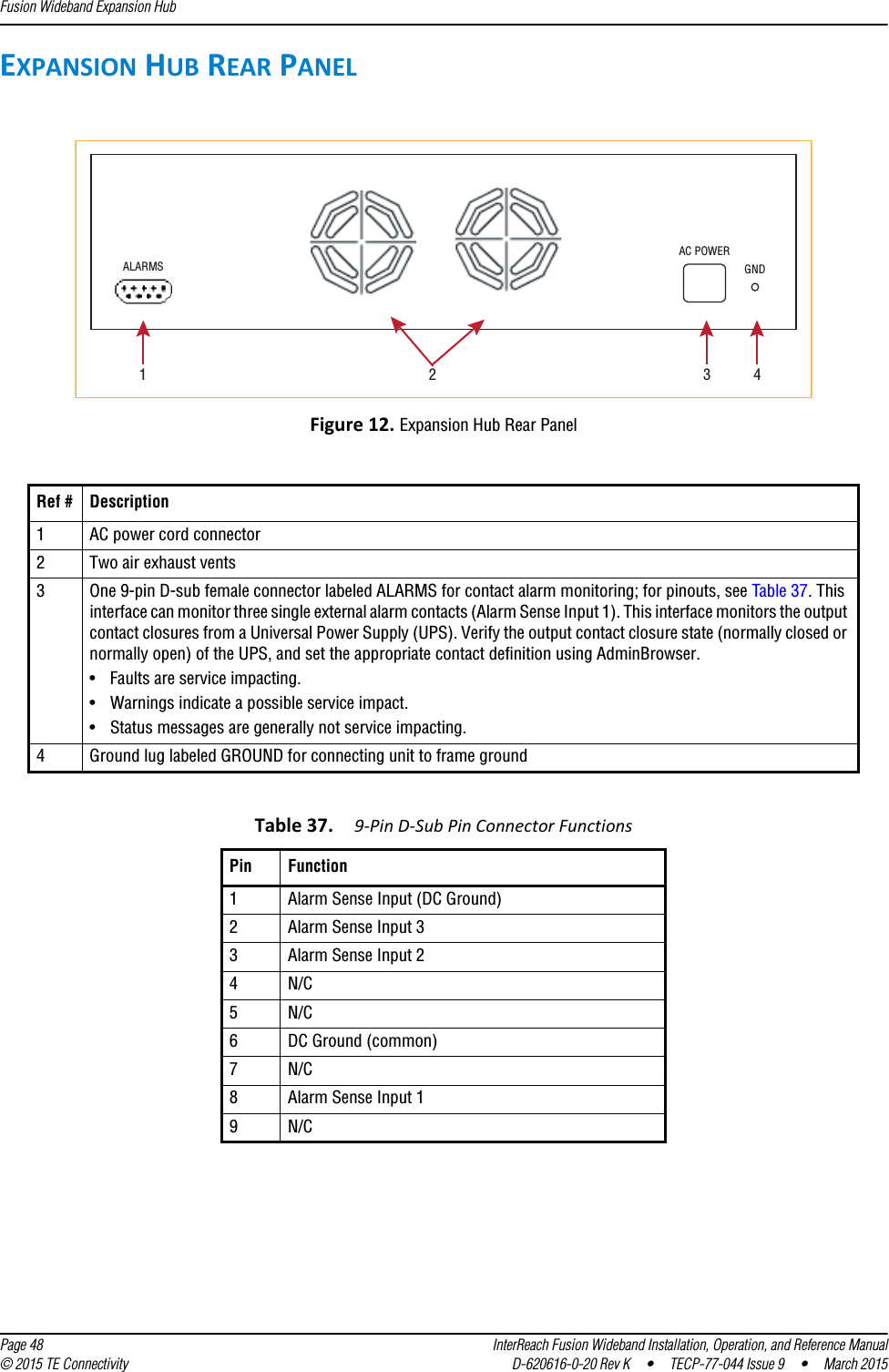

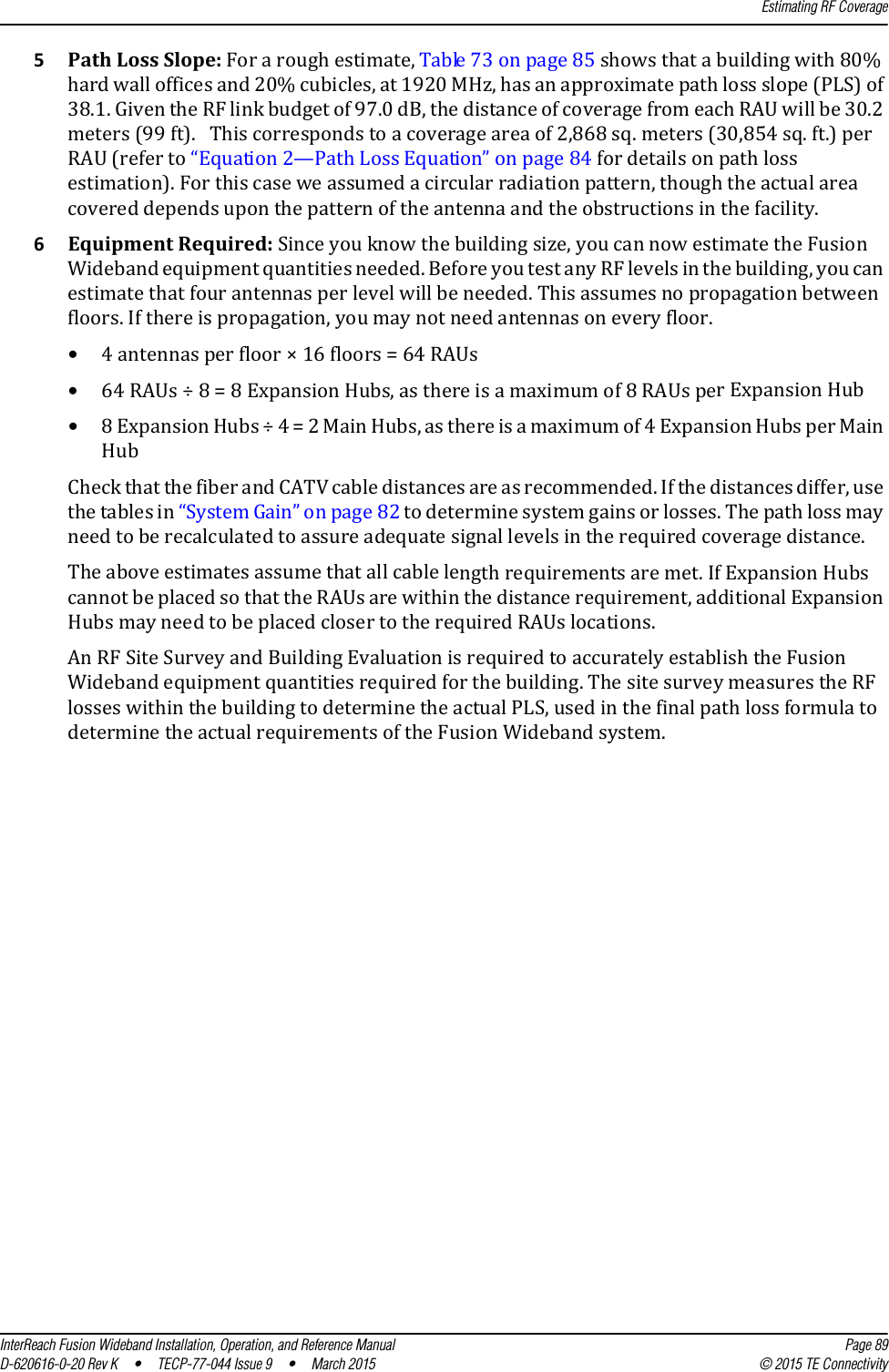
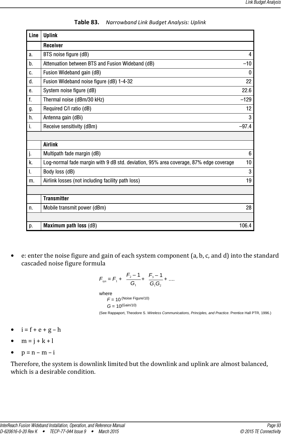
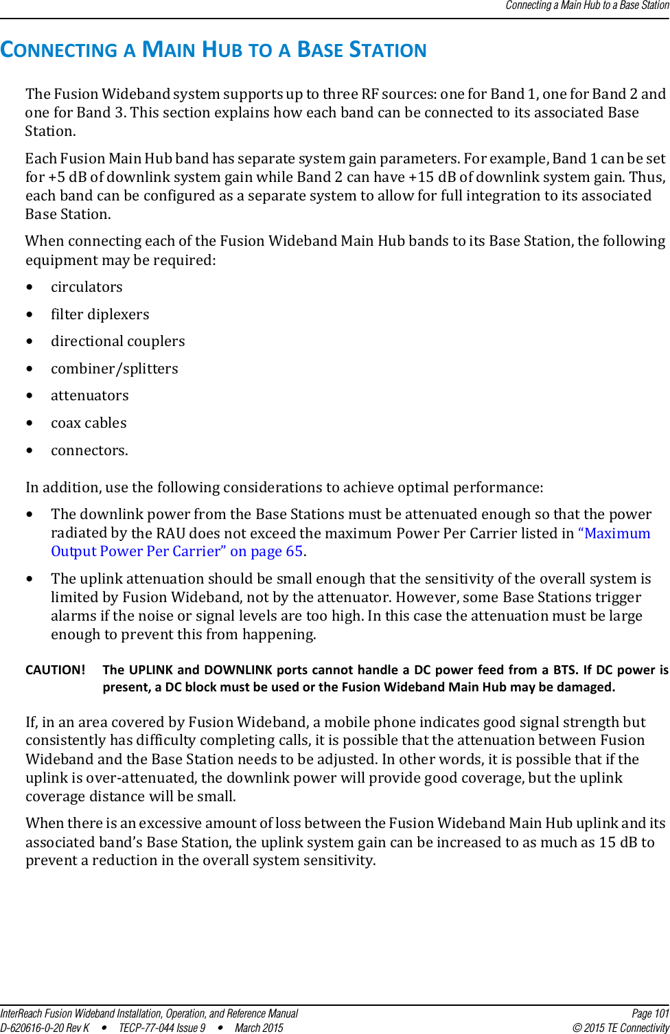
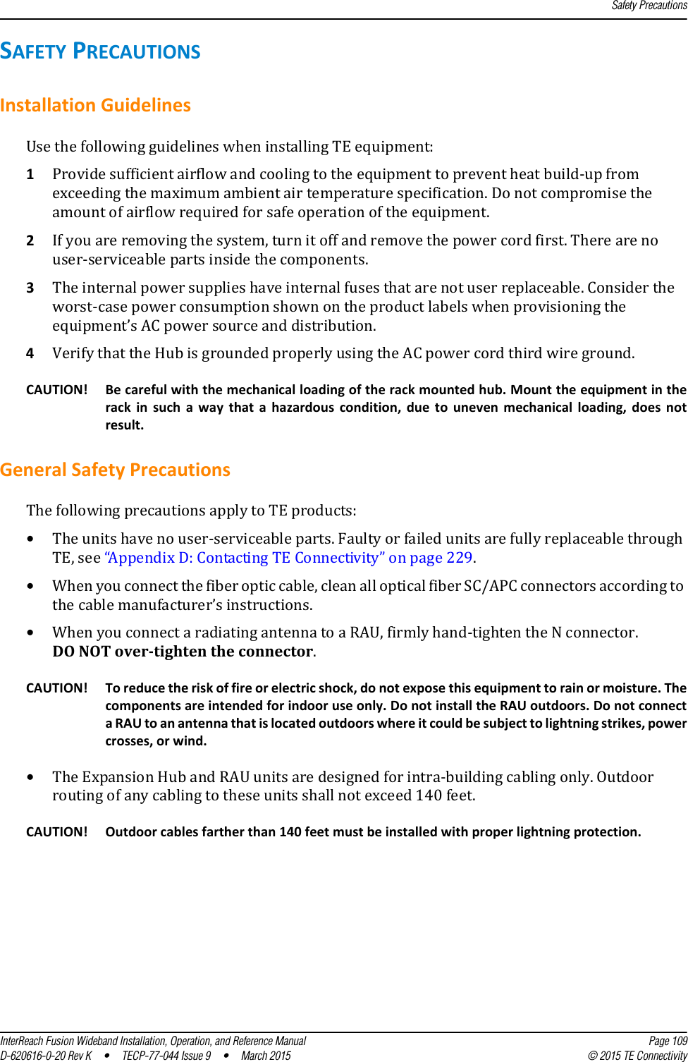
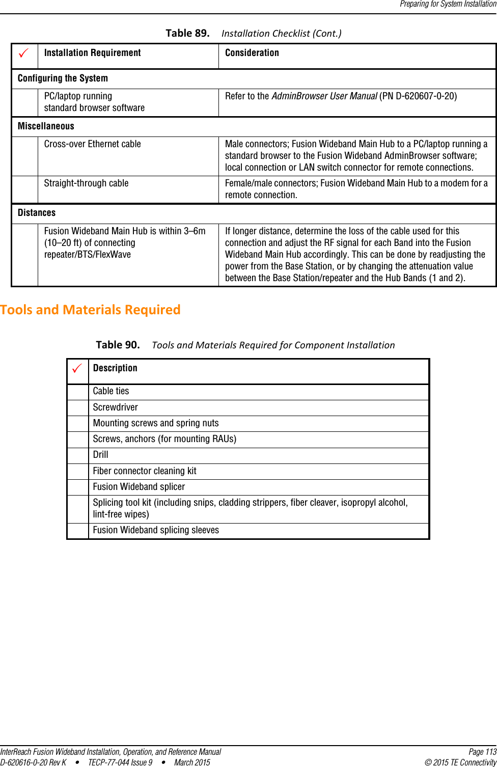
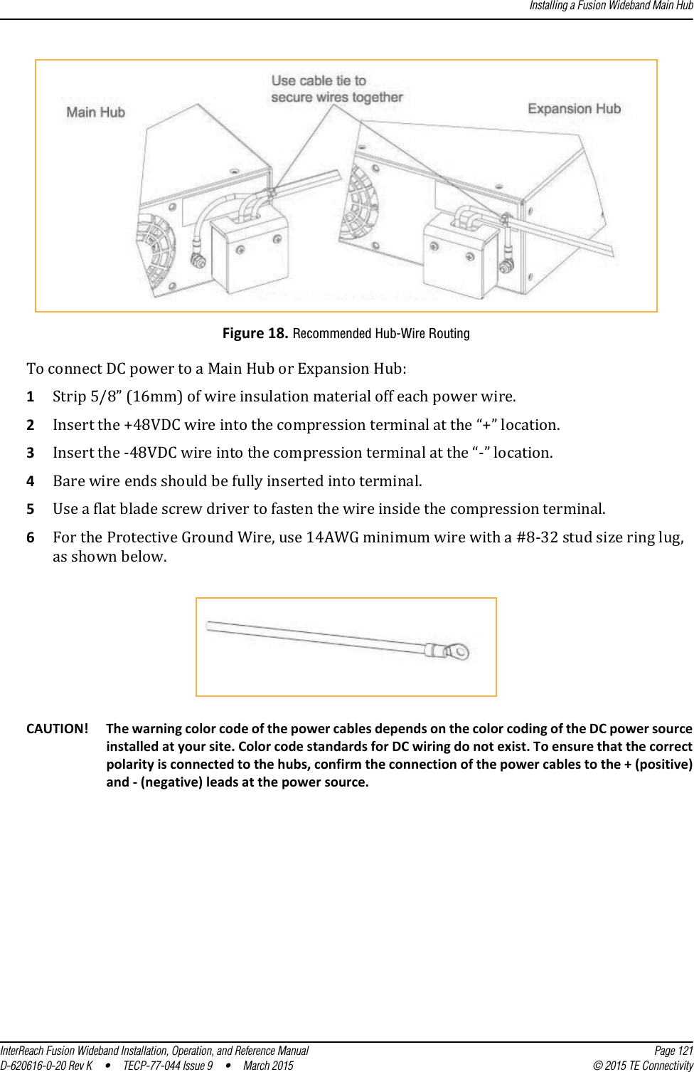
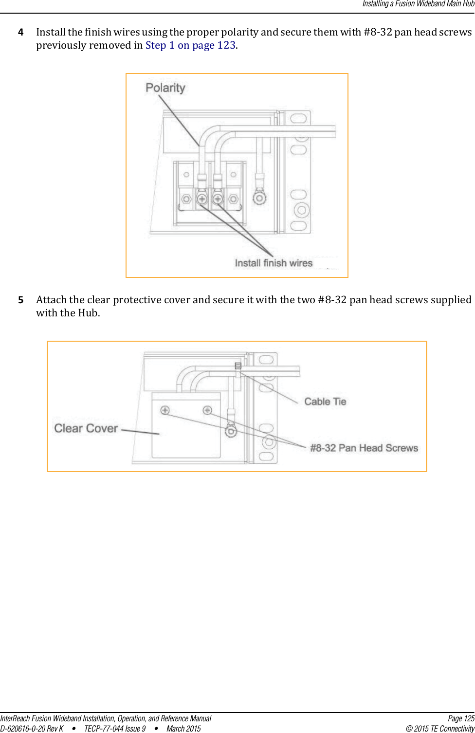
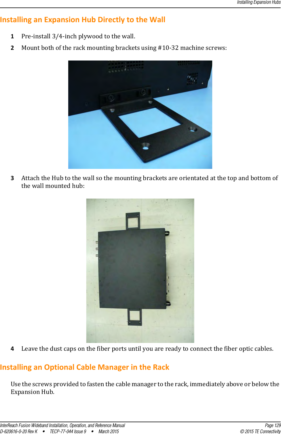
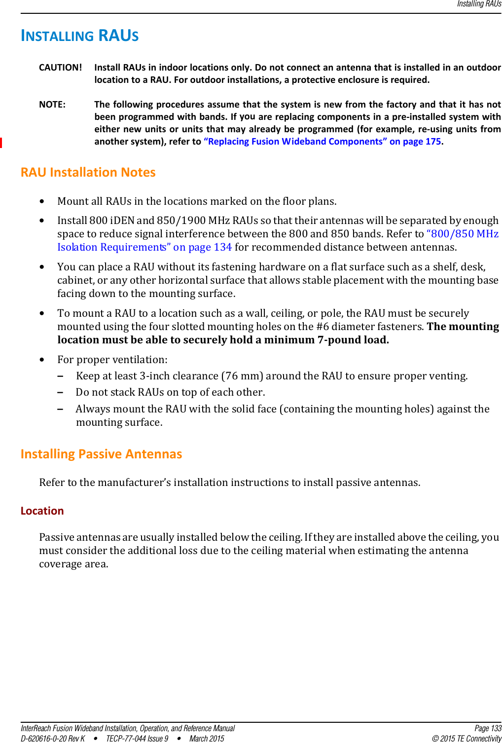
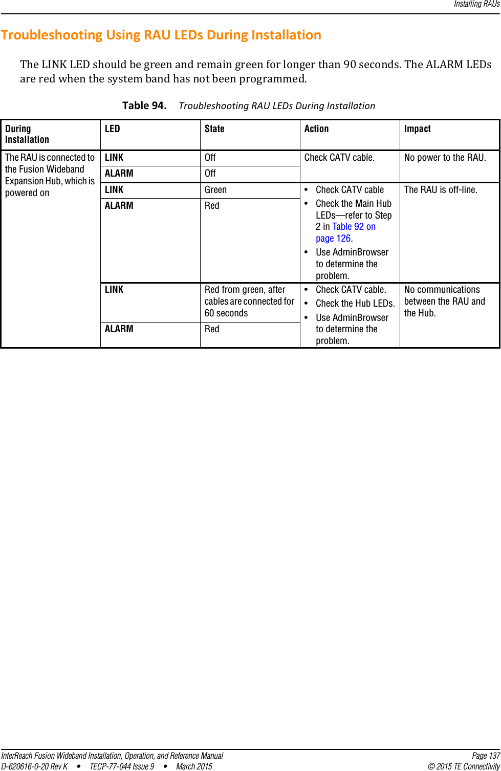
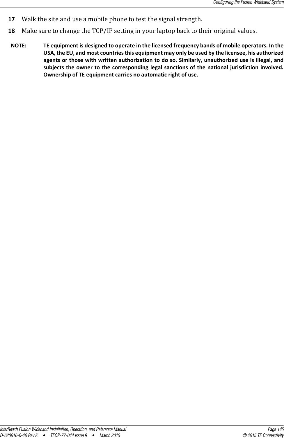
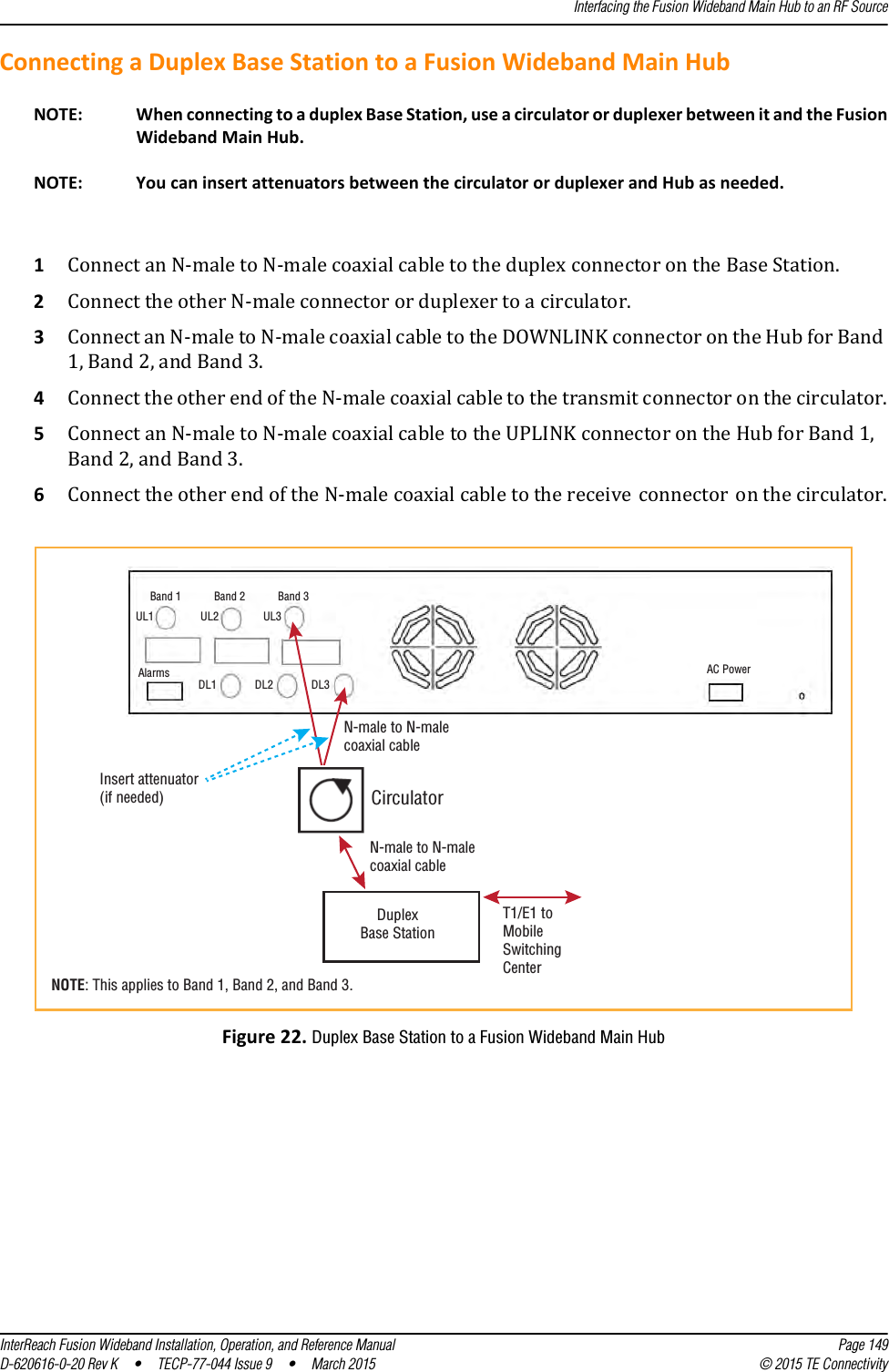
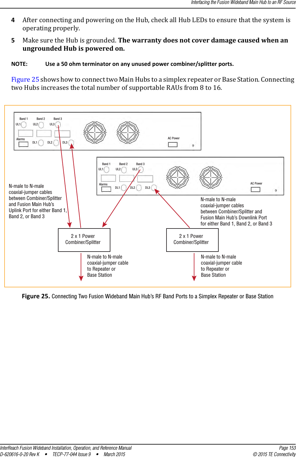
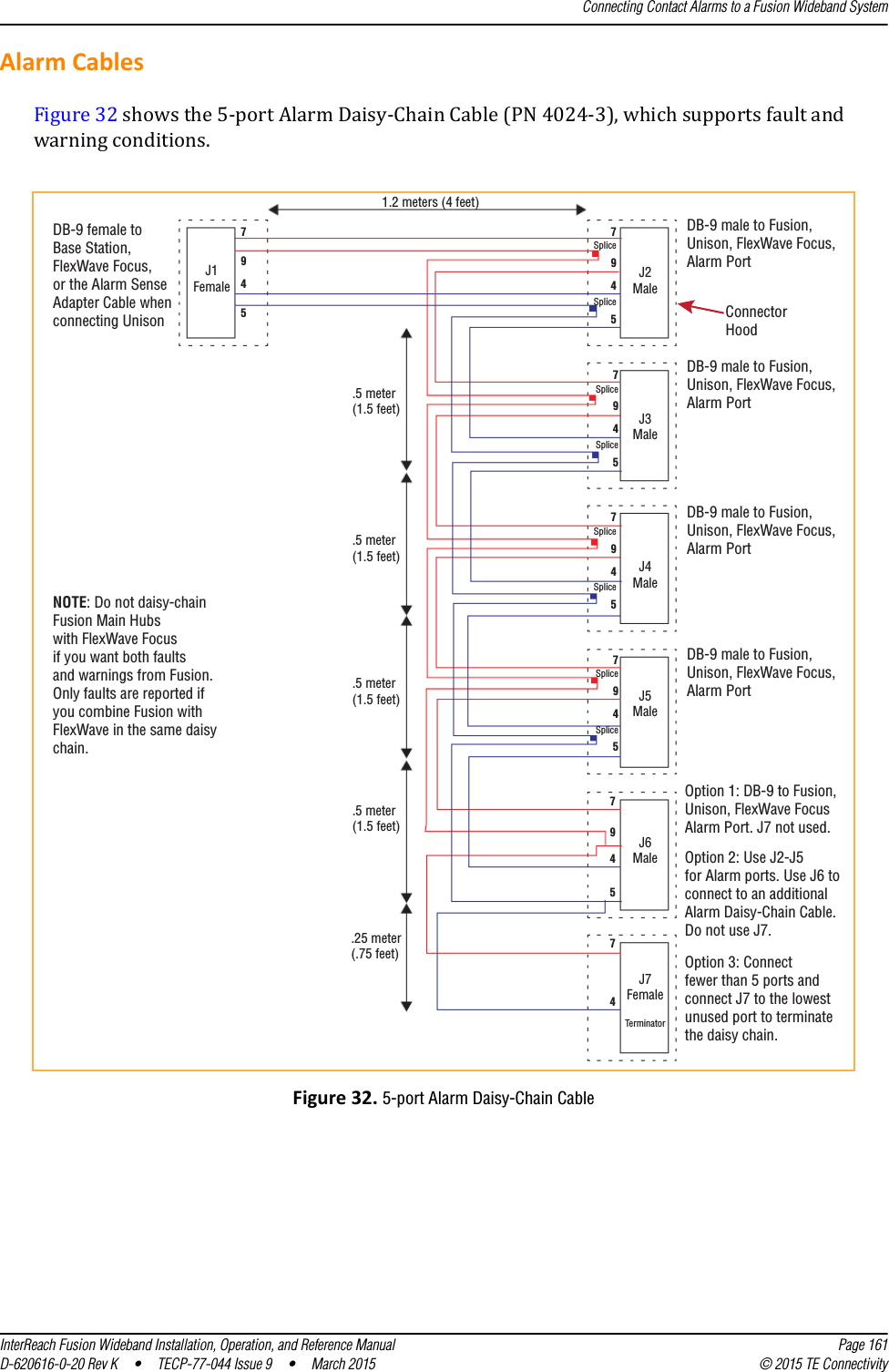

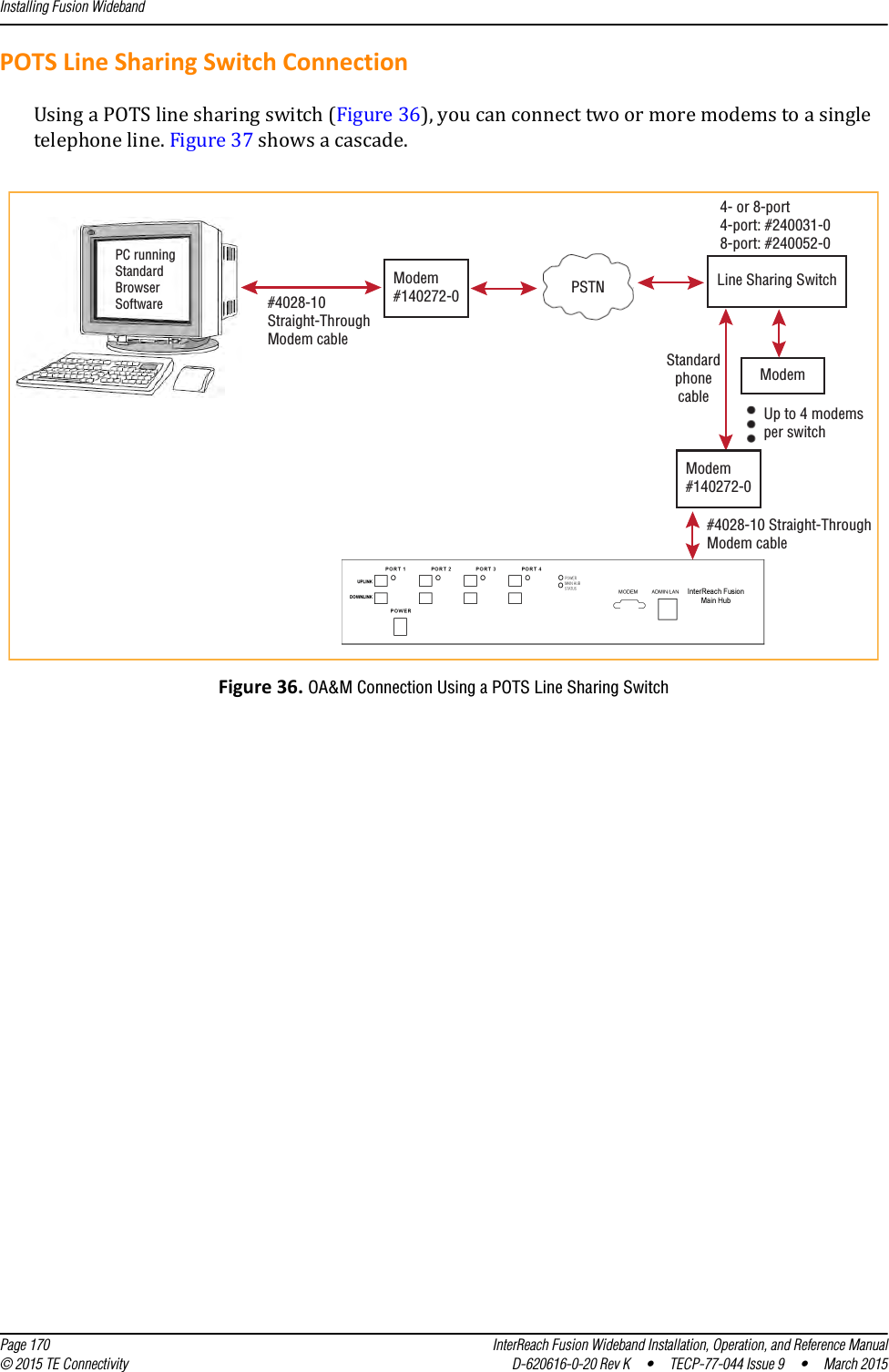


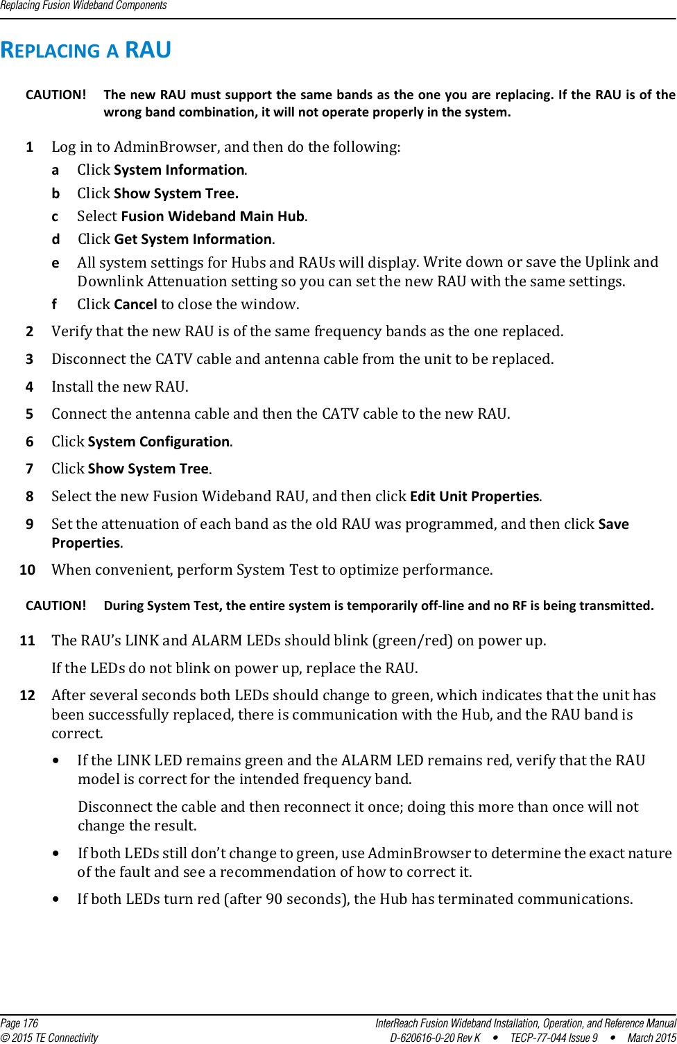

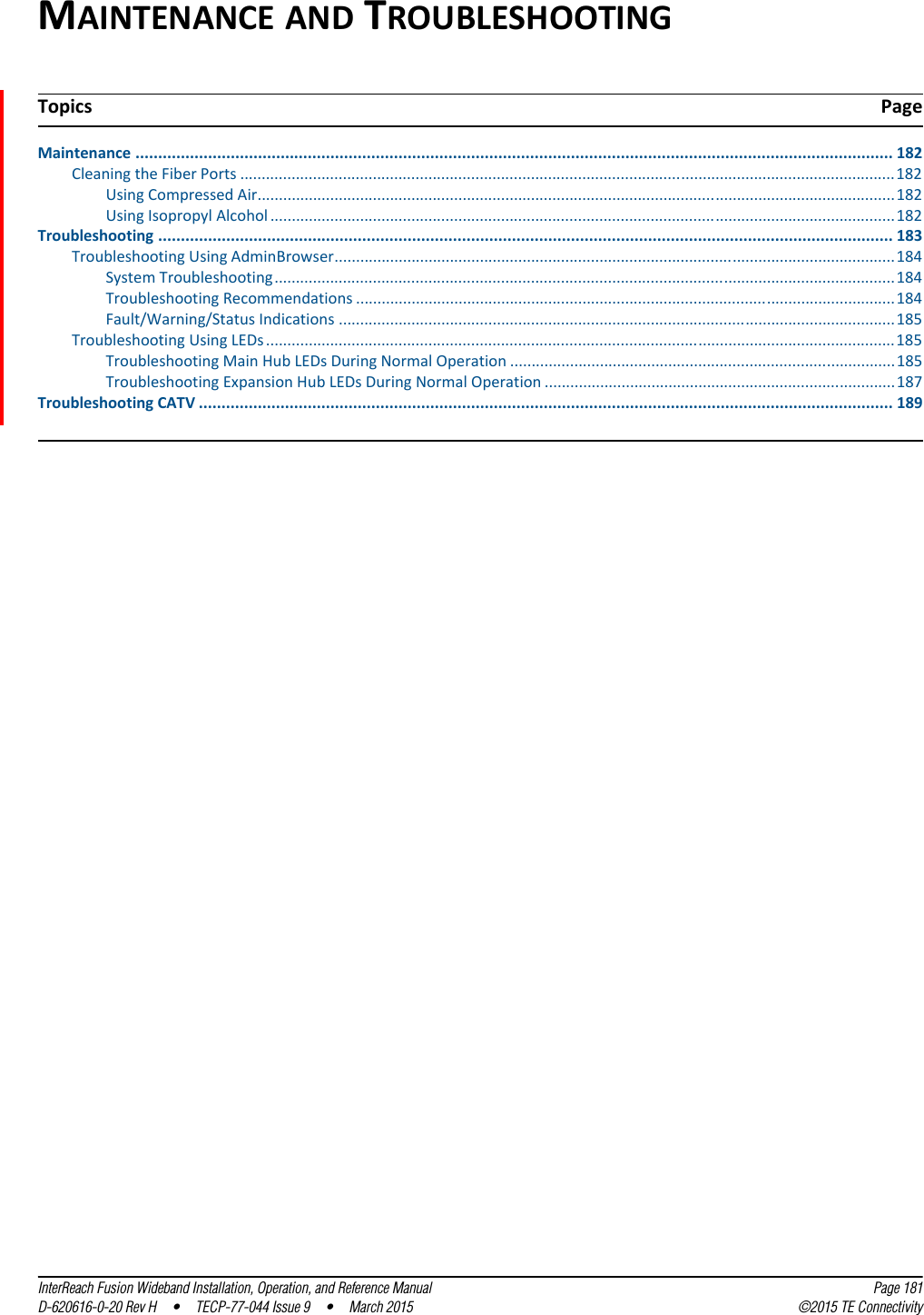
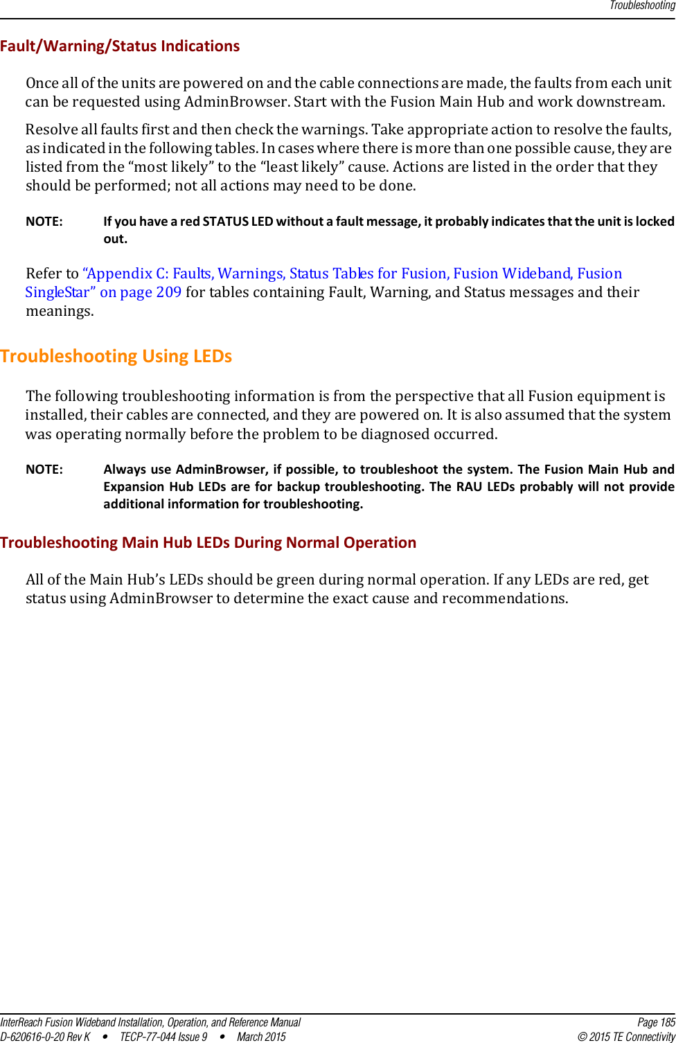
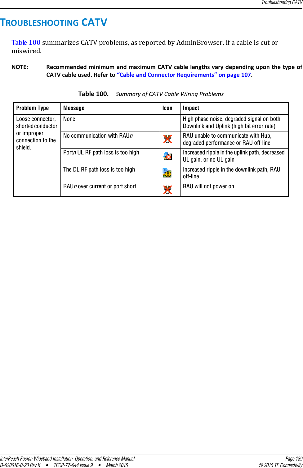

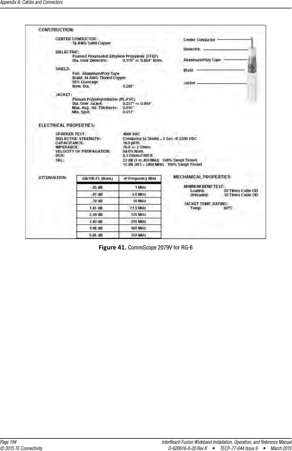

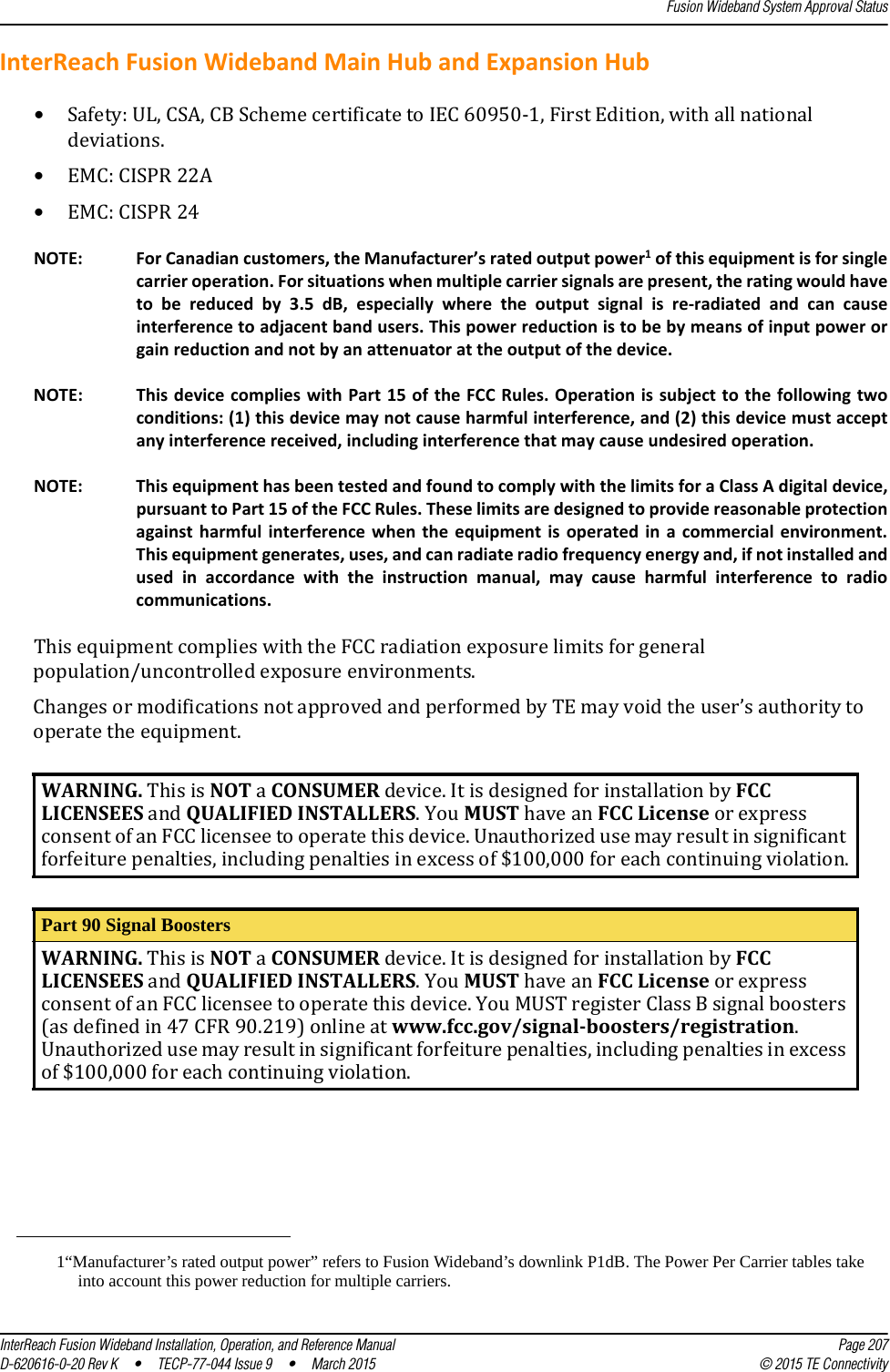
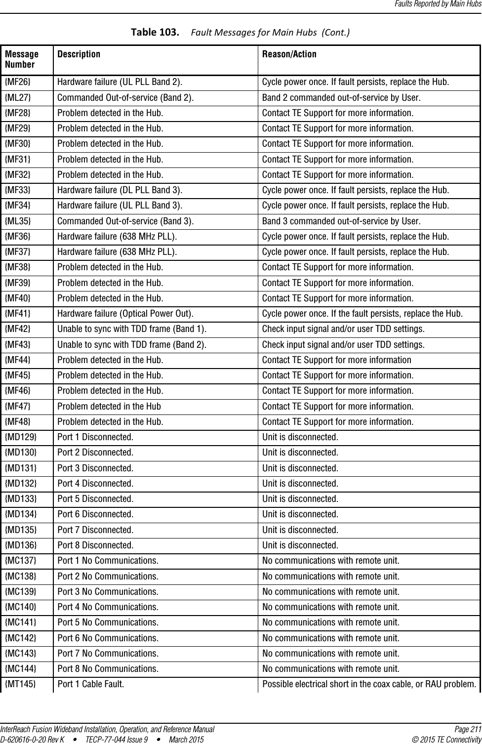
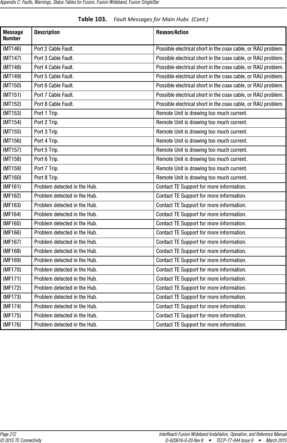
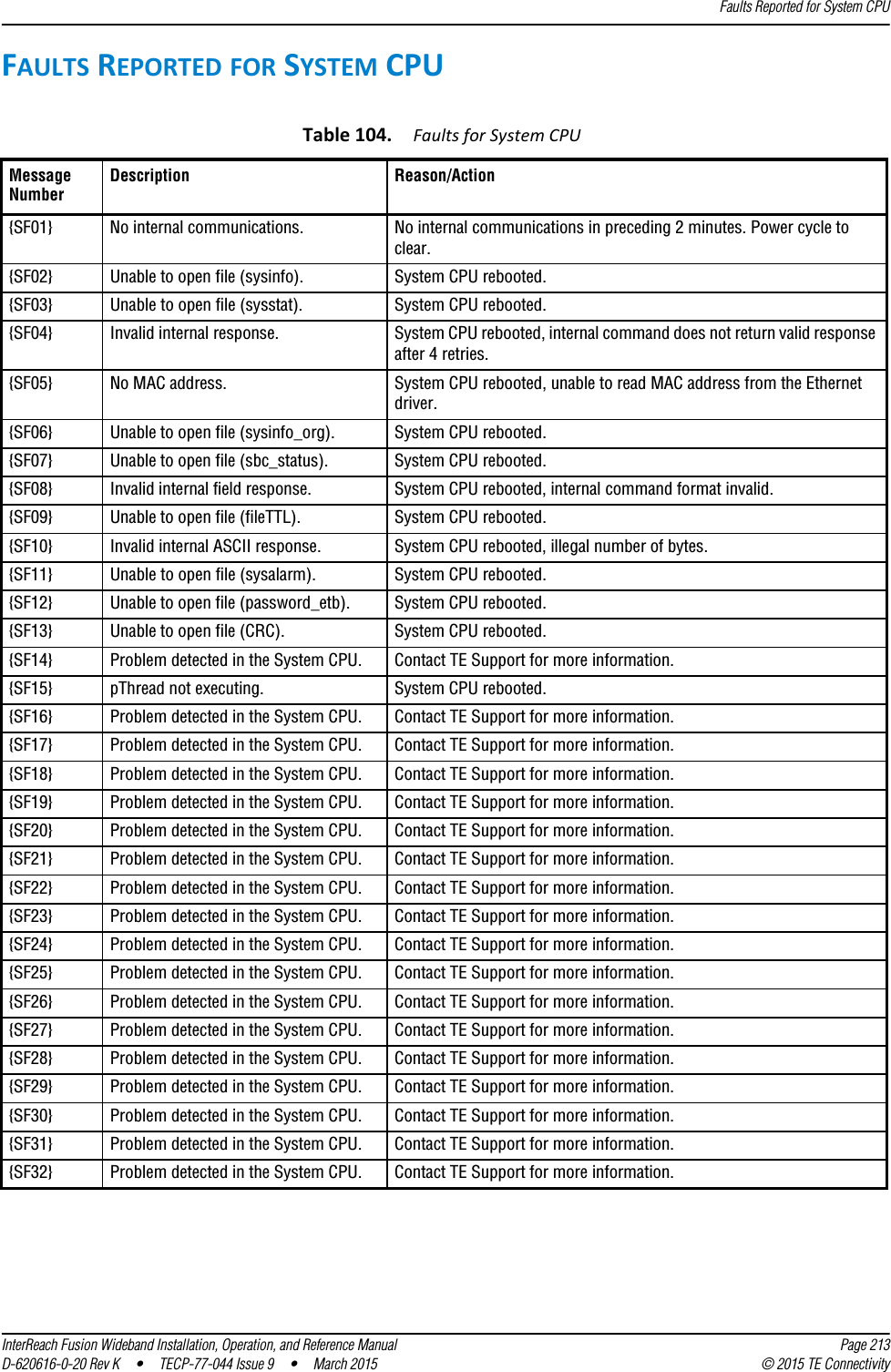
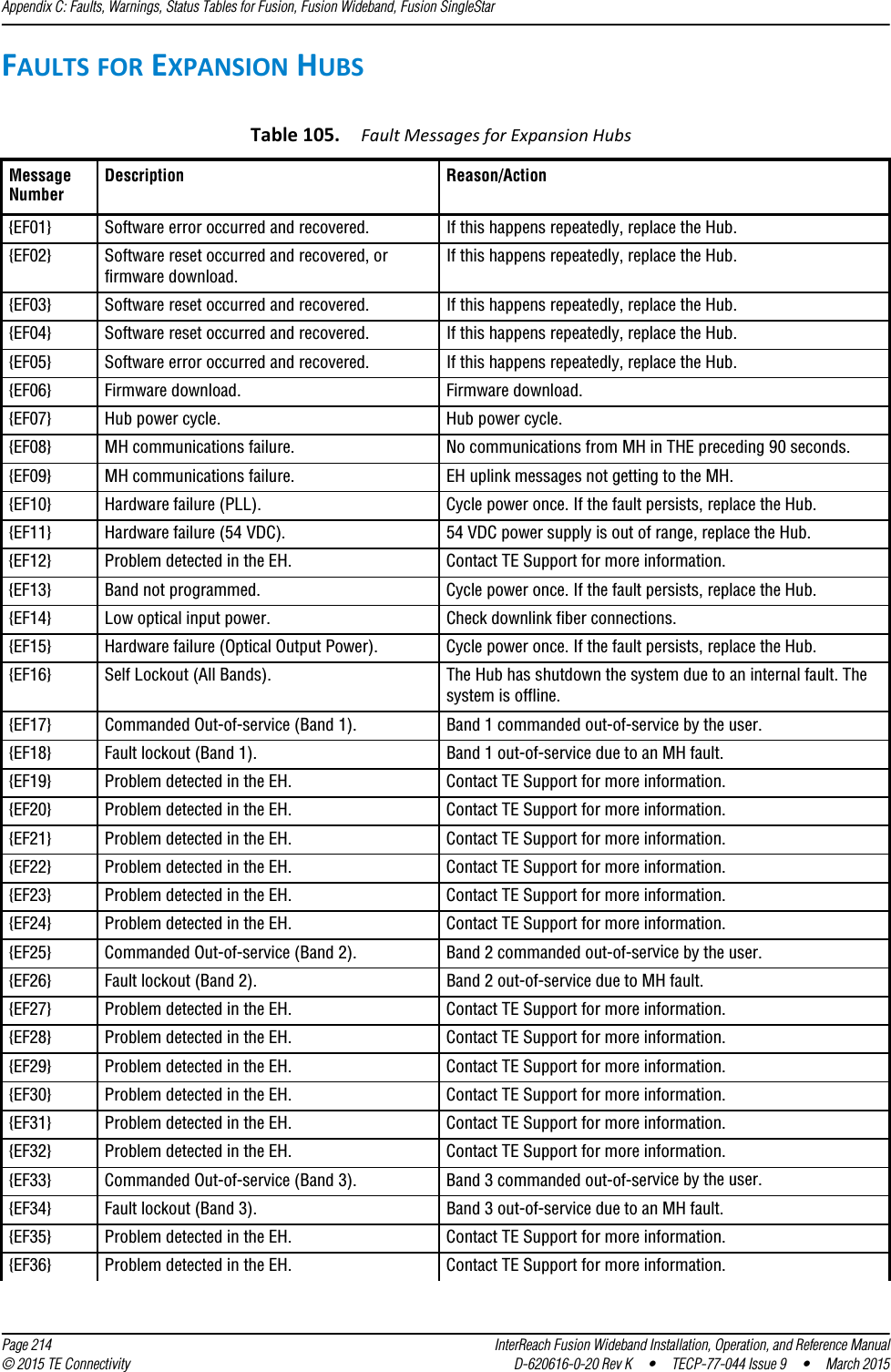
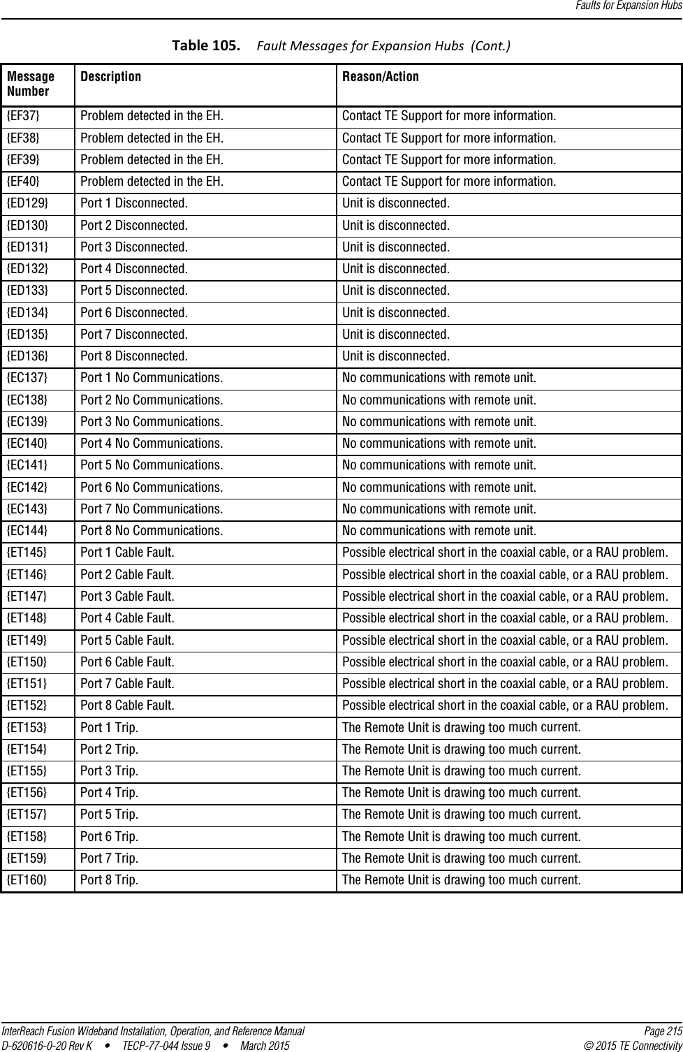
![Messages for Main HubsInterReach Fusion Wideband Installation, Operation, and Reference Manual Page 217D-620616-0-20 Rev K • TECP-77-044 Issue 9 • March 2015 © 2015 TE ConnectivityMESSAGES FOR MAIN HUBSWarning MessagesWarnings alert you to conditions that indicate possible service impact. Warnings are displayed in the Messages pane in red lettering.Before addressing warnings, ensure that all faults are resolved. Take appropriate action to resolve the warnings, as indicated in the following tables.NOTE: AdminBrowser v000007 or higher displays events (faults, warnings, or status messages) depending on your view preference. To change your view preference, refer to Section 3.5, “Faults, Warnings, and Status Messages” of the Fusion Installation, Operation, and Maintenance Manual.Status MessagesStatus messages alert you to conditions that are important, but generally do not impact service. Status messages alert you to conditions that are important, but generally do not impact service. Status messages are displayed in the Messages pane in blue lettering.NOTE: AdminBrowser v000007 or higher displays events (faults, warnings, or status messages) depending on your view preference. To change your view preference, refer to Section 3.5, “Faults, Warnings, and Status Messages” of the Fusion Installation, Operation, and Maintenance Manual.NOTE: The icons displayed in the system status tree assume that there are no other faults, warnings, or status present.In Table 107 on page 218, the message number is in the following form:[Mnn]/X where •nn equals the message number•X equals the default of one of the following–S—Status–W—Warning.](https://usermanual.wiki/ADC-Telecommunications/F0851-111/User-Guide-2572832-Page-225.png)
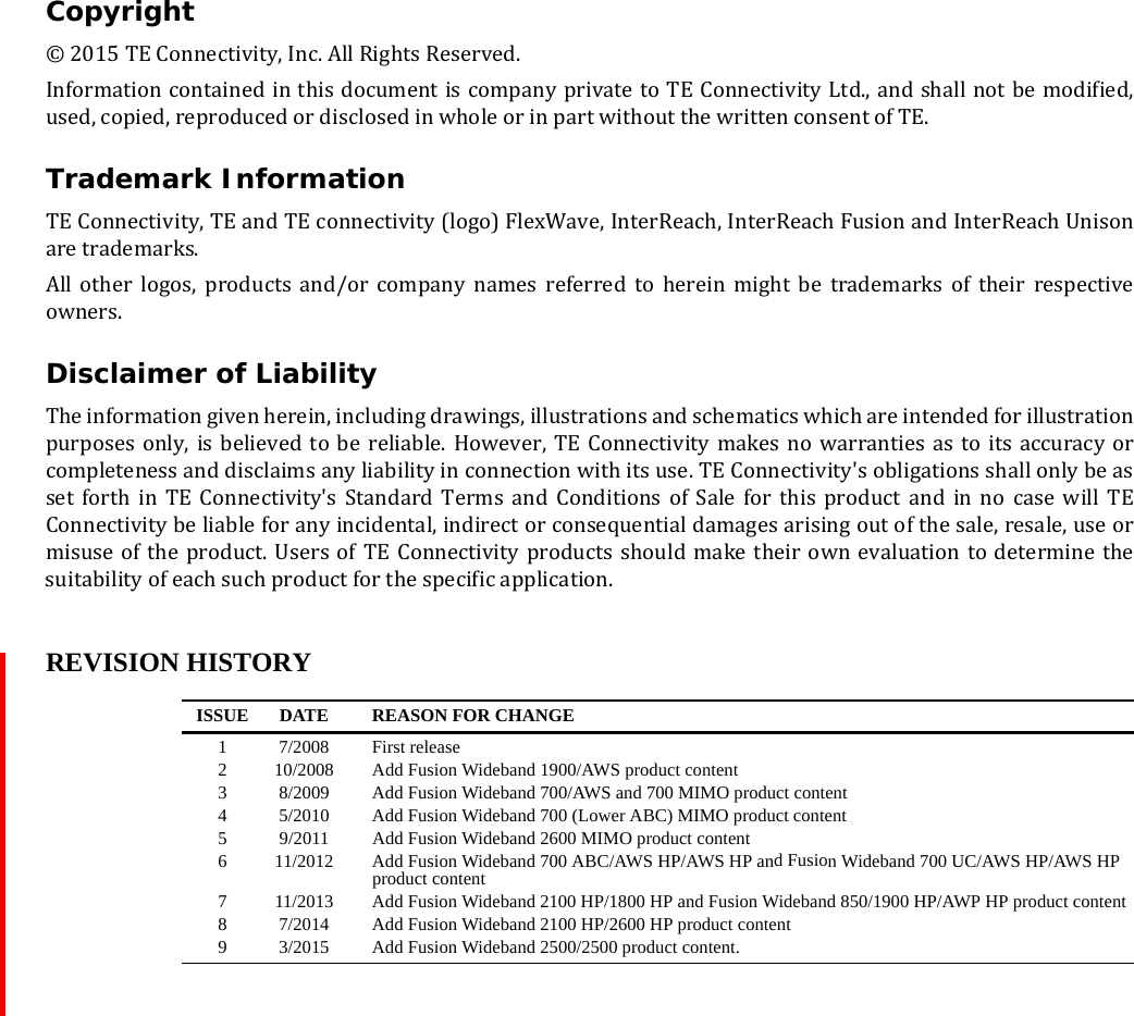
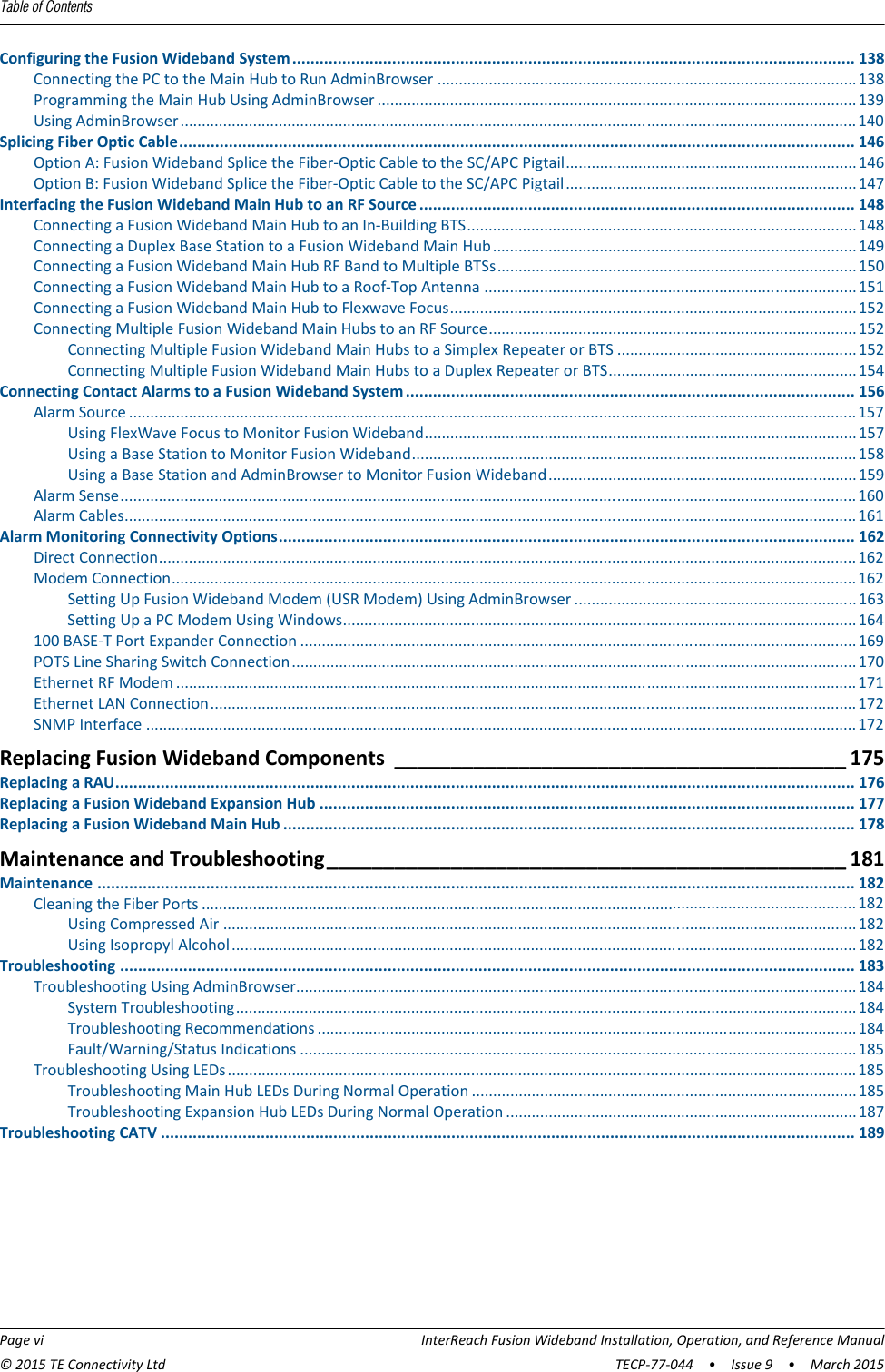
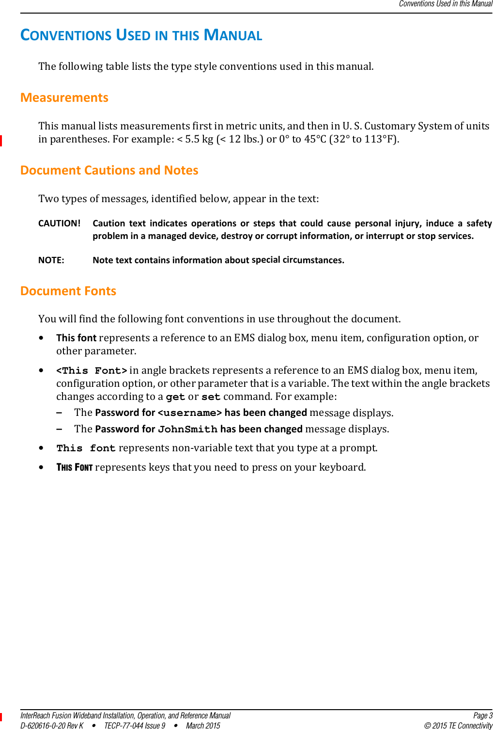
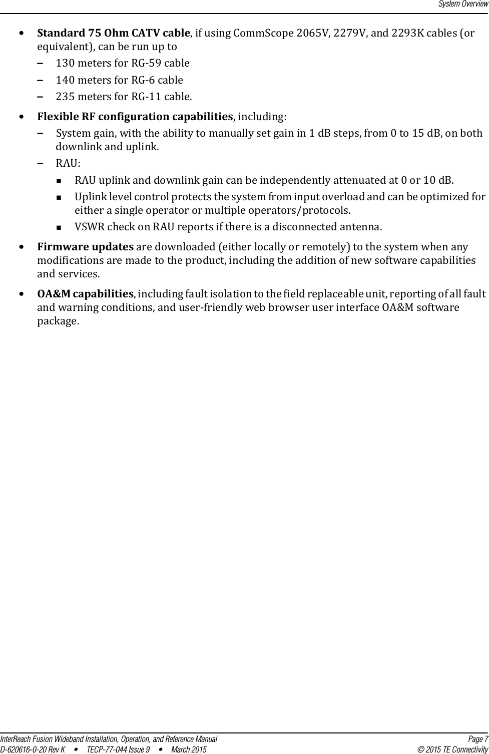
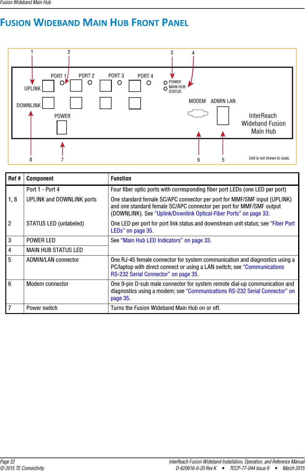
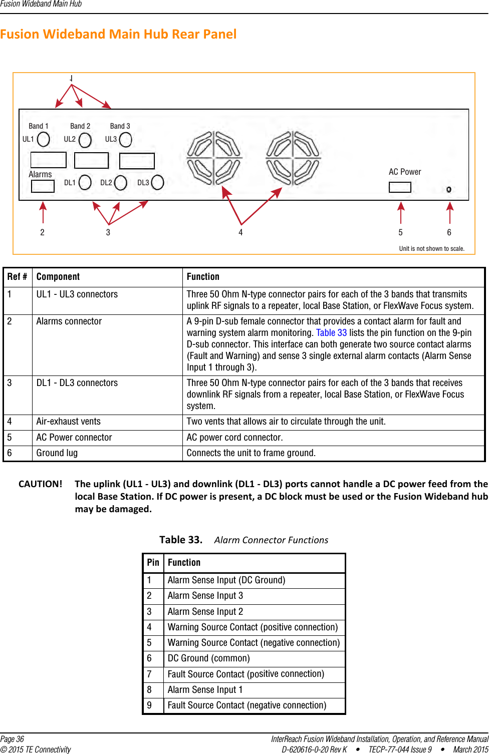
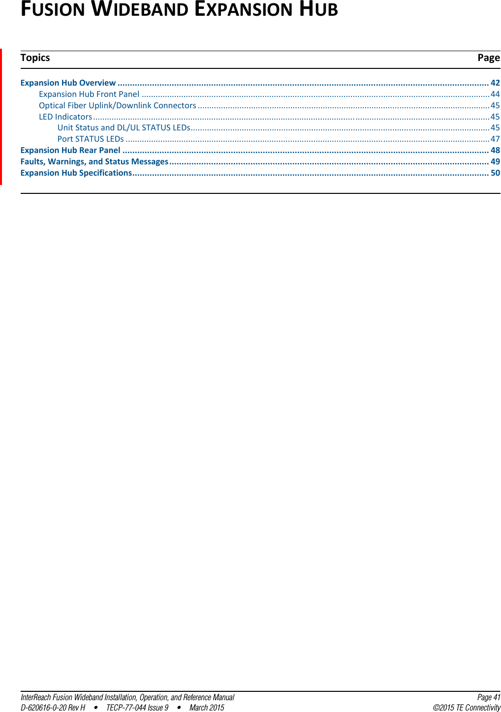
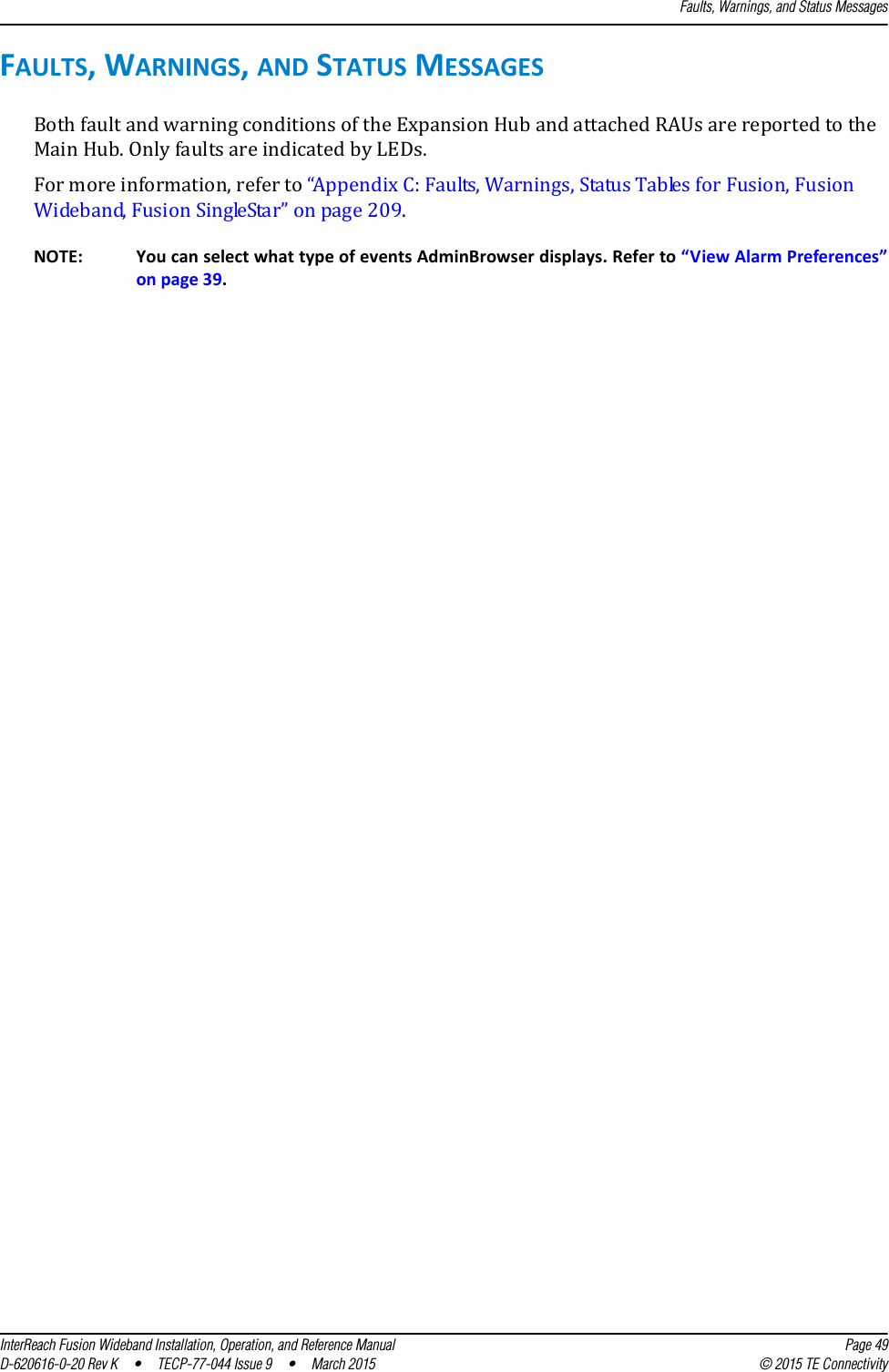
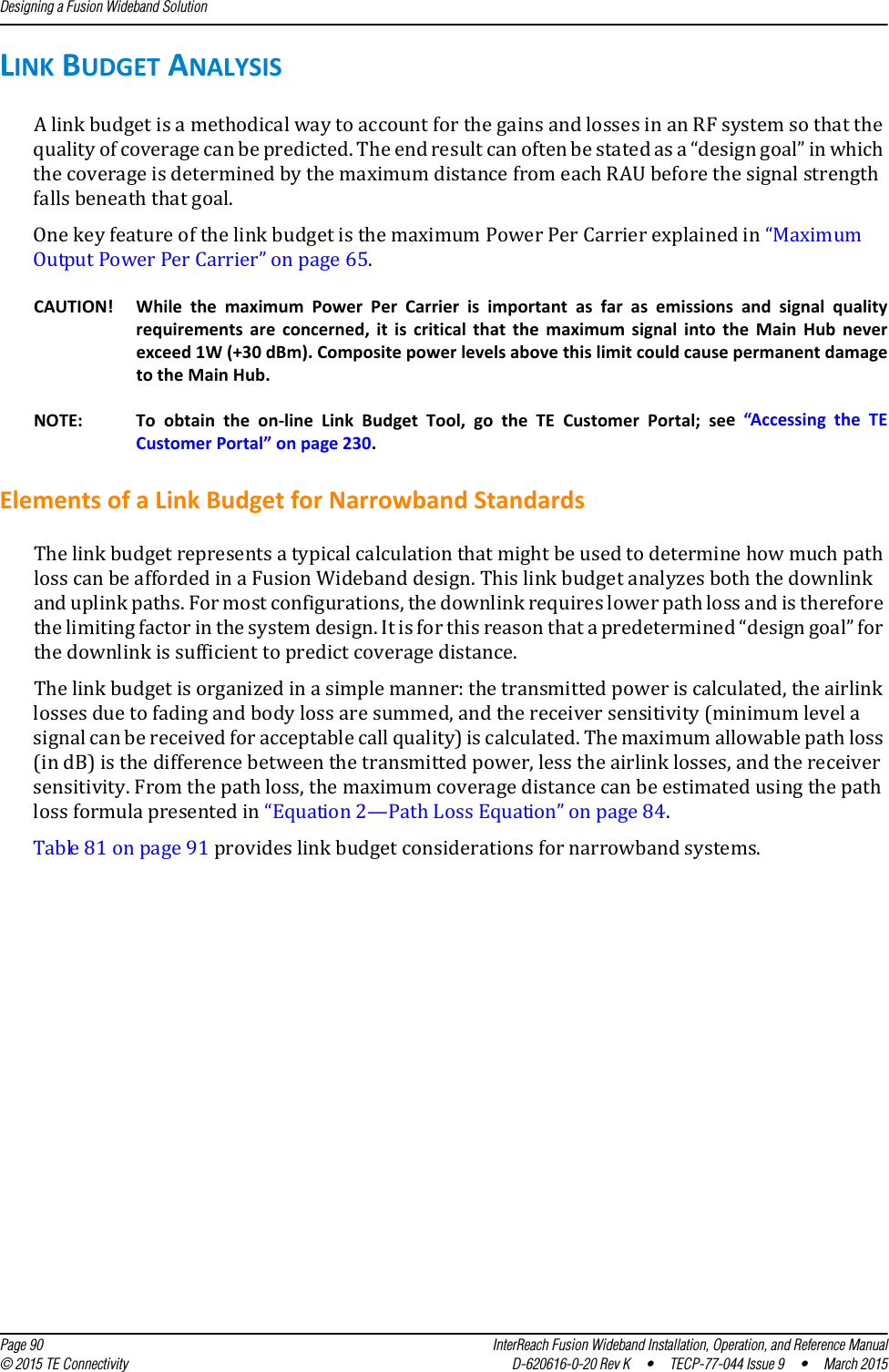
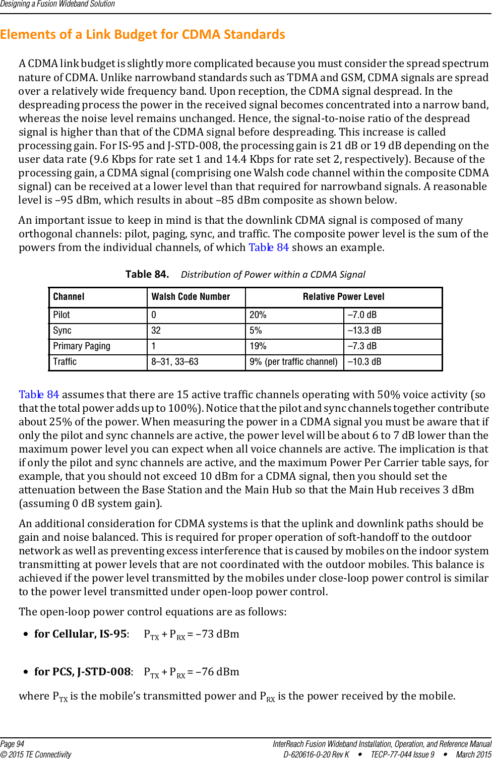
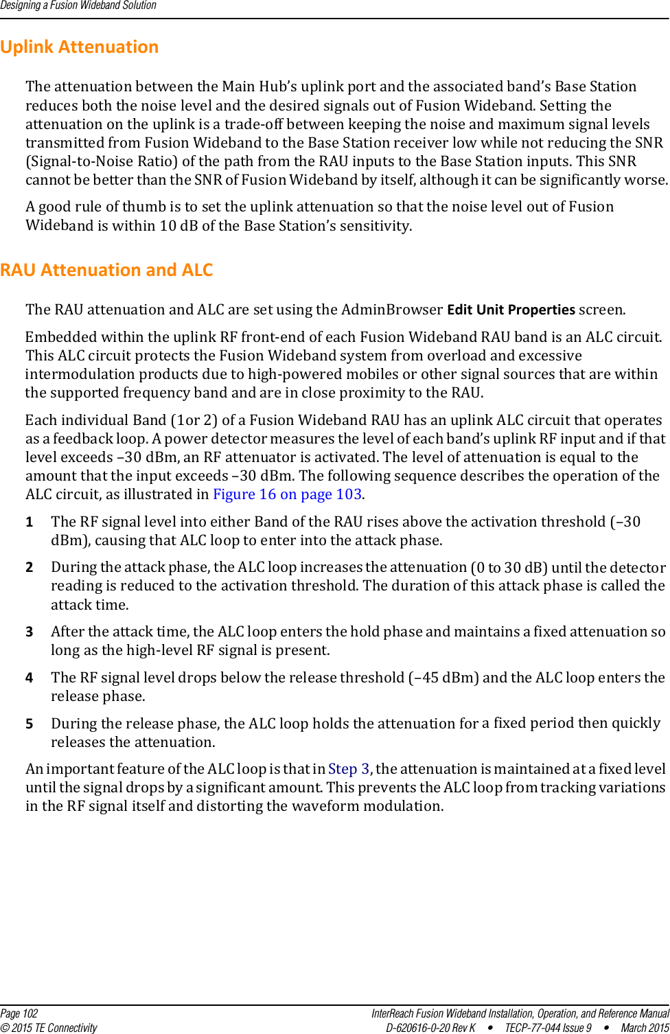
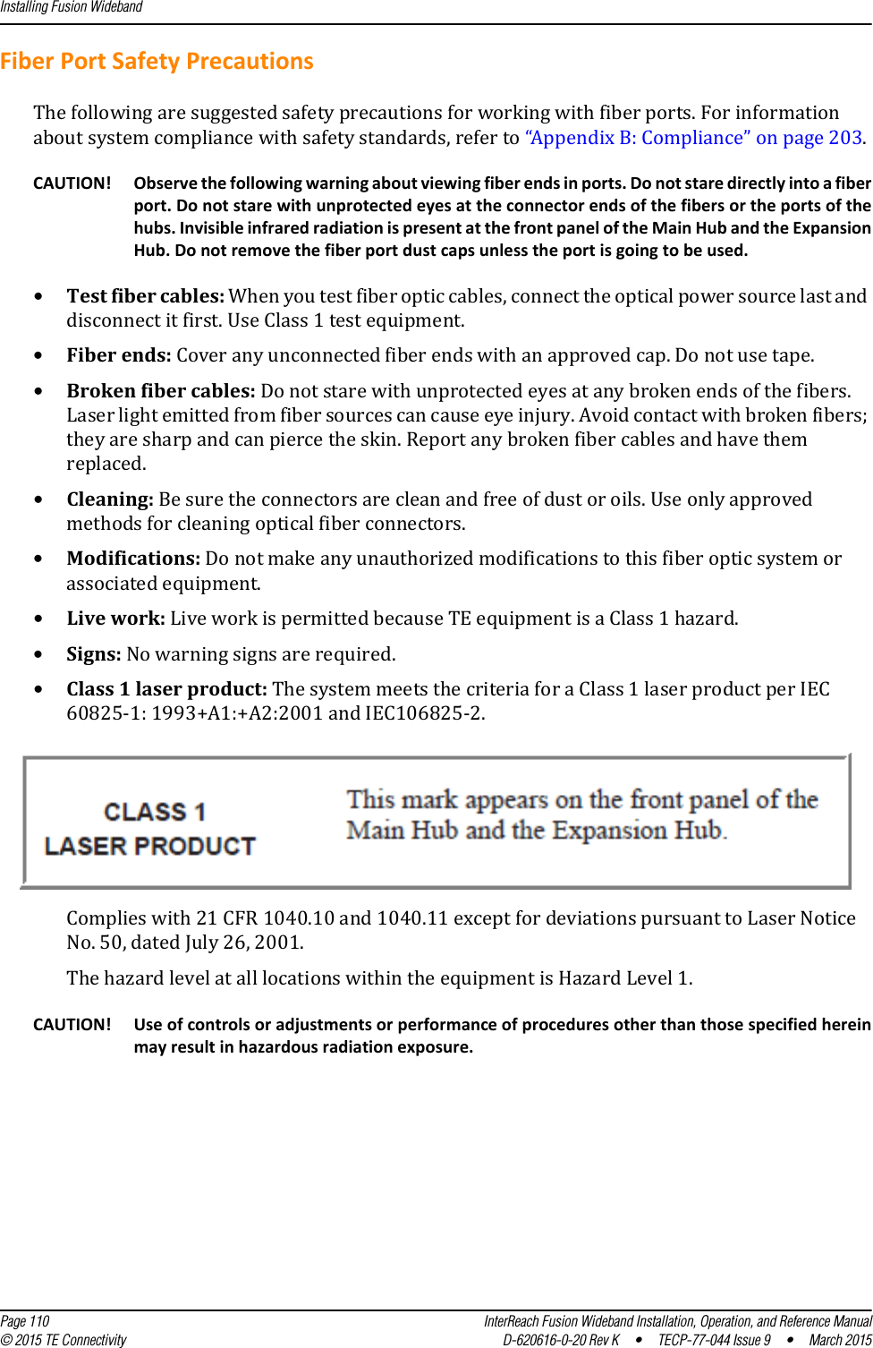
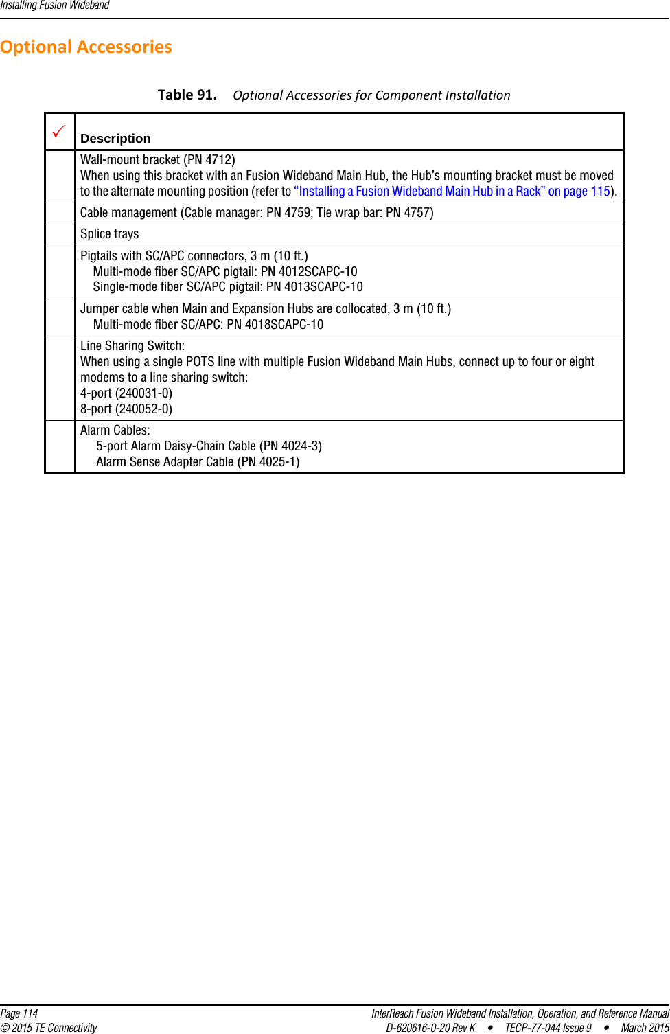
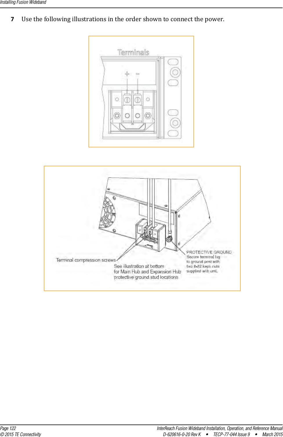
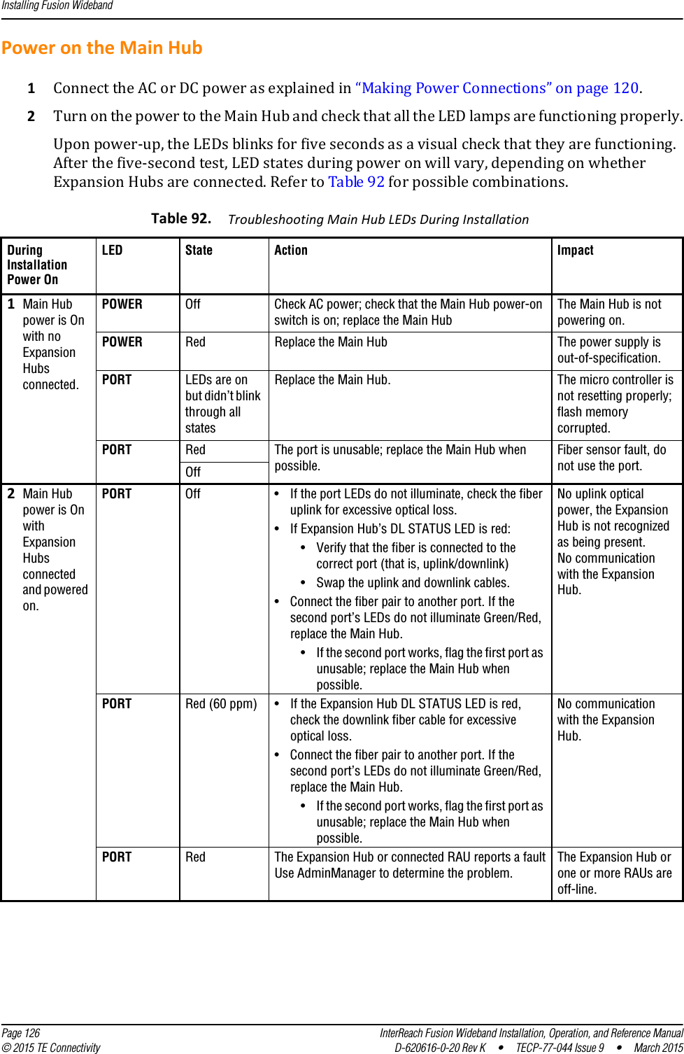
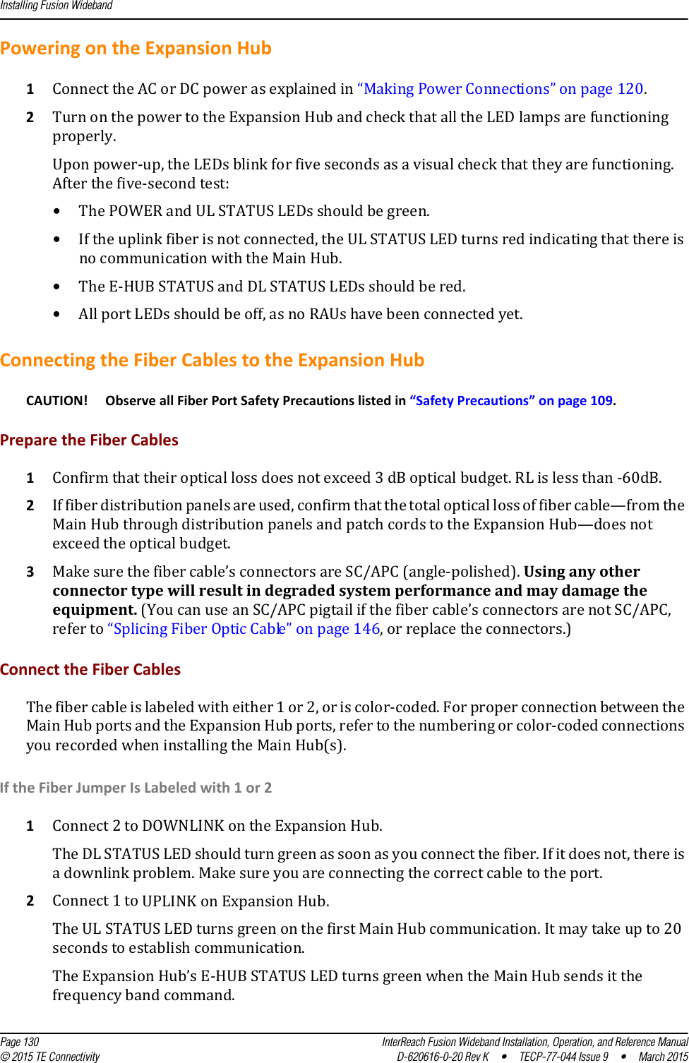
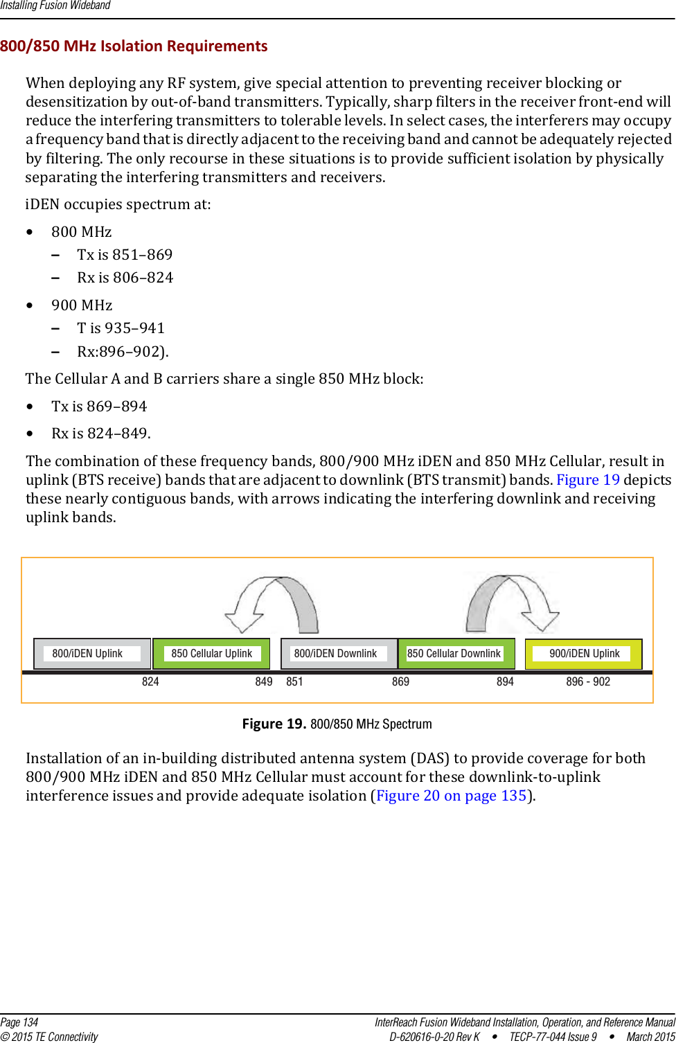
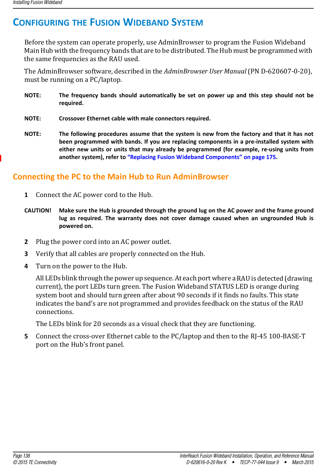
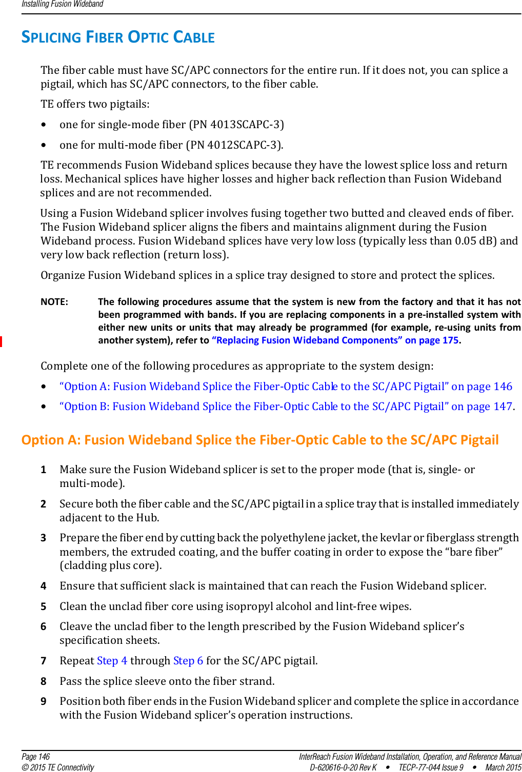
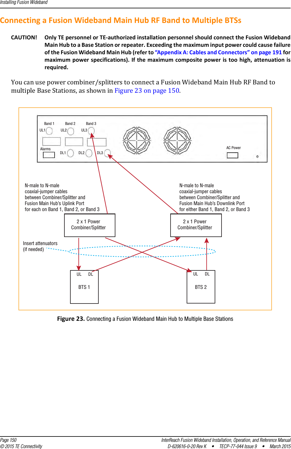
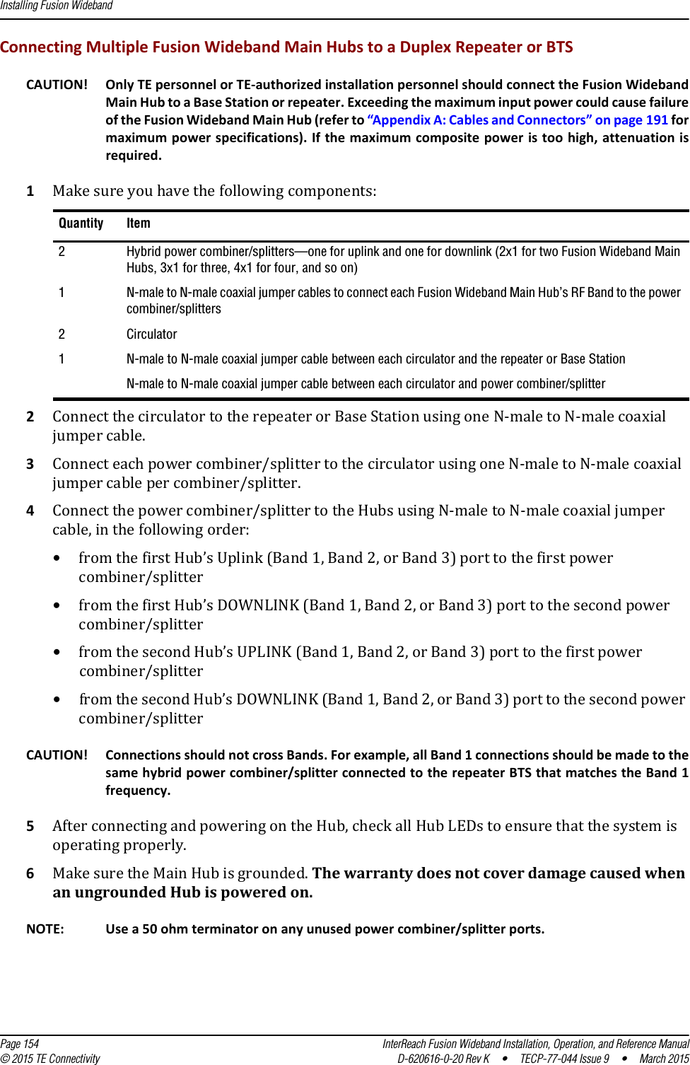
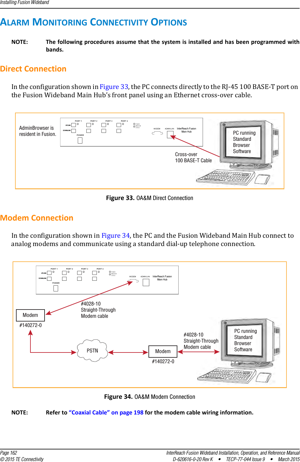
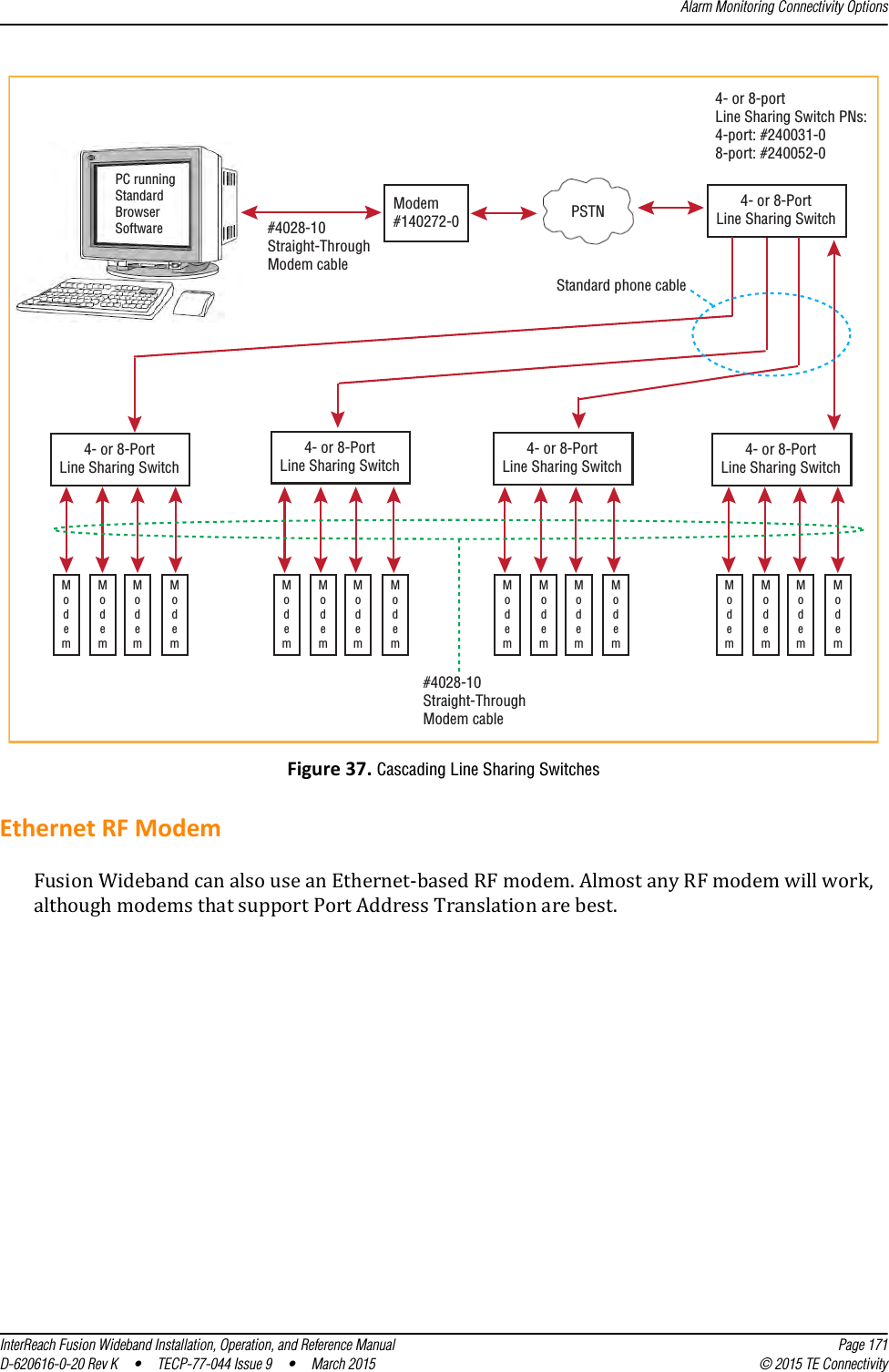
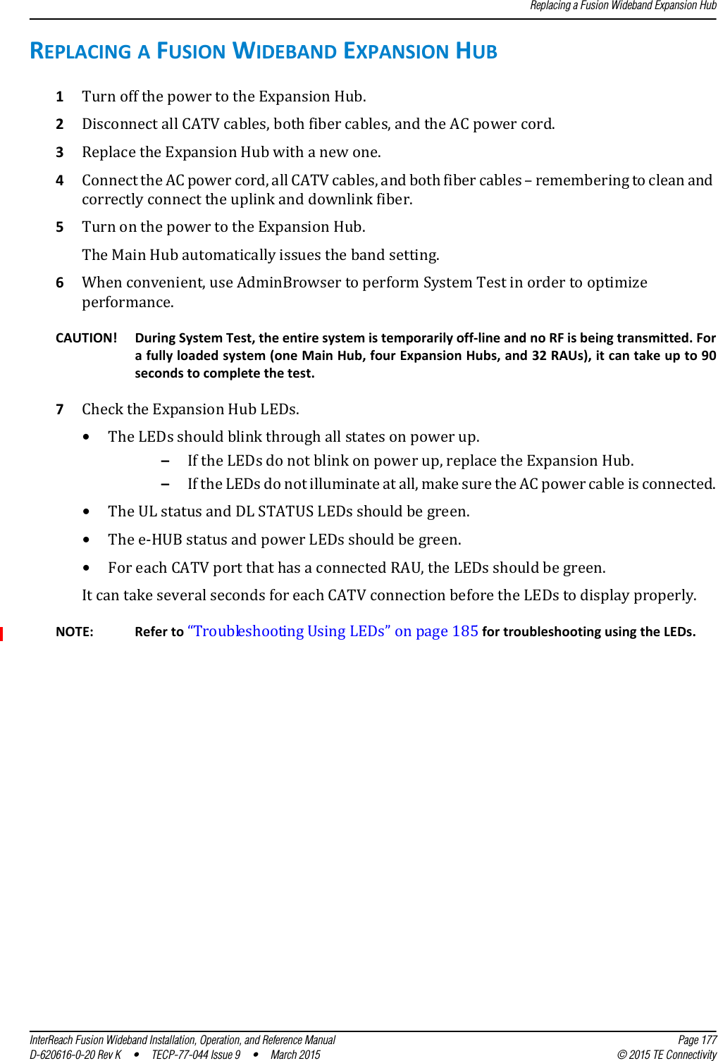
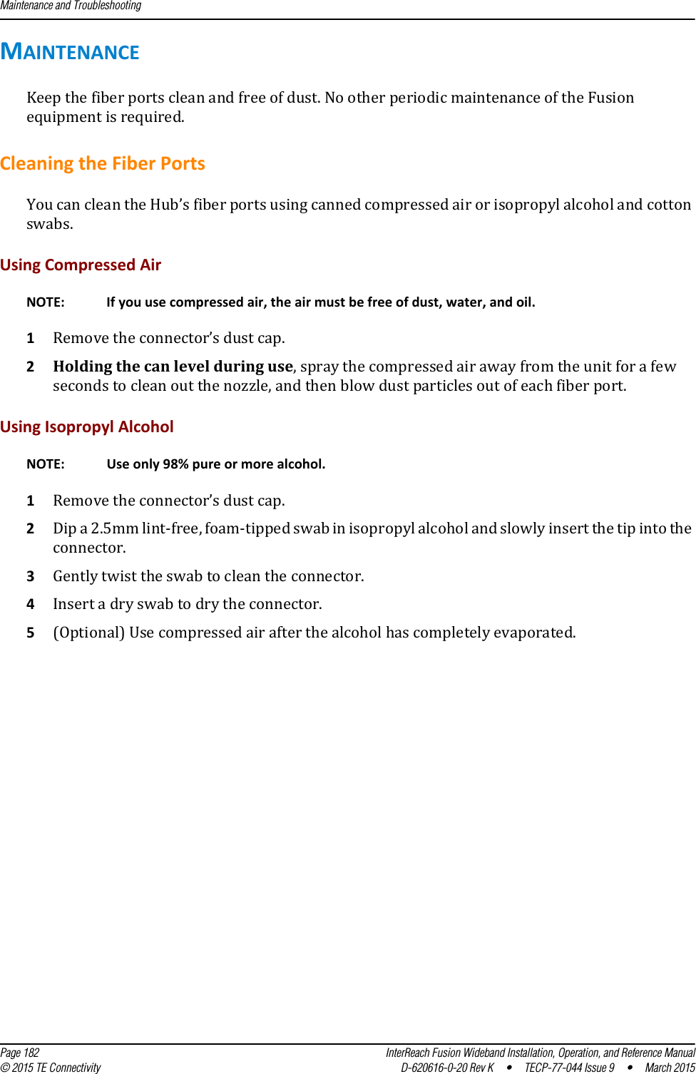
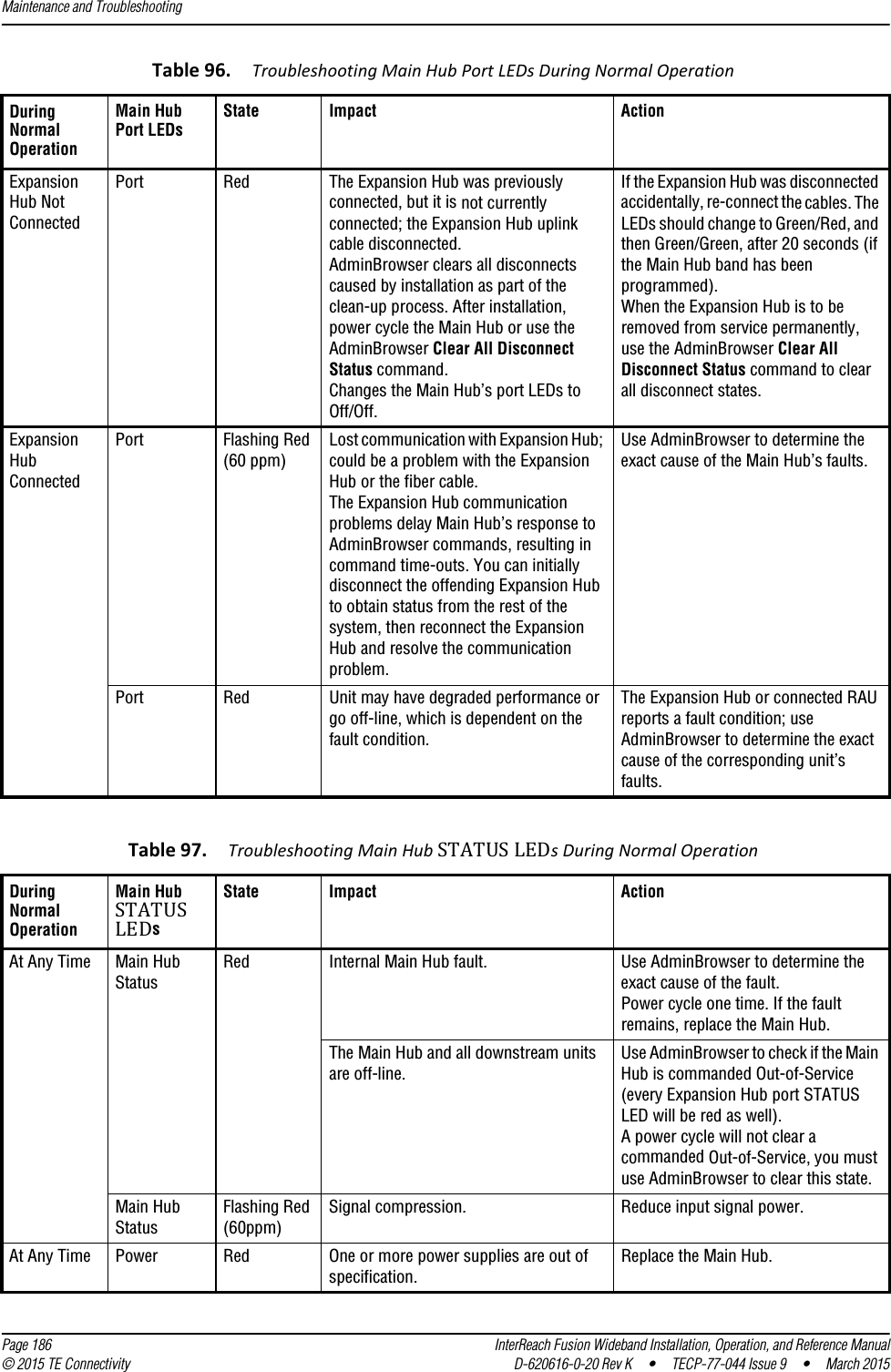
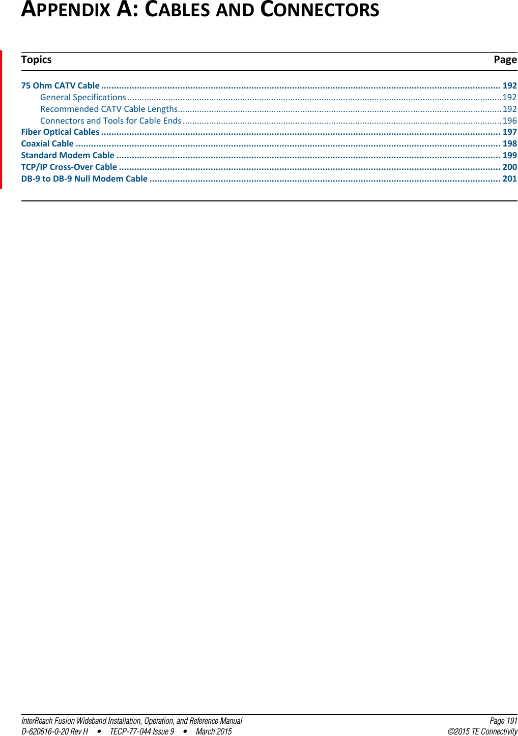
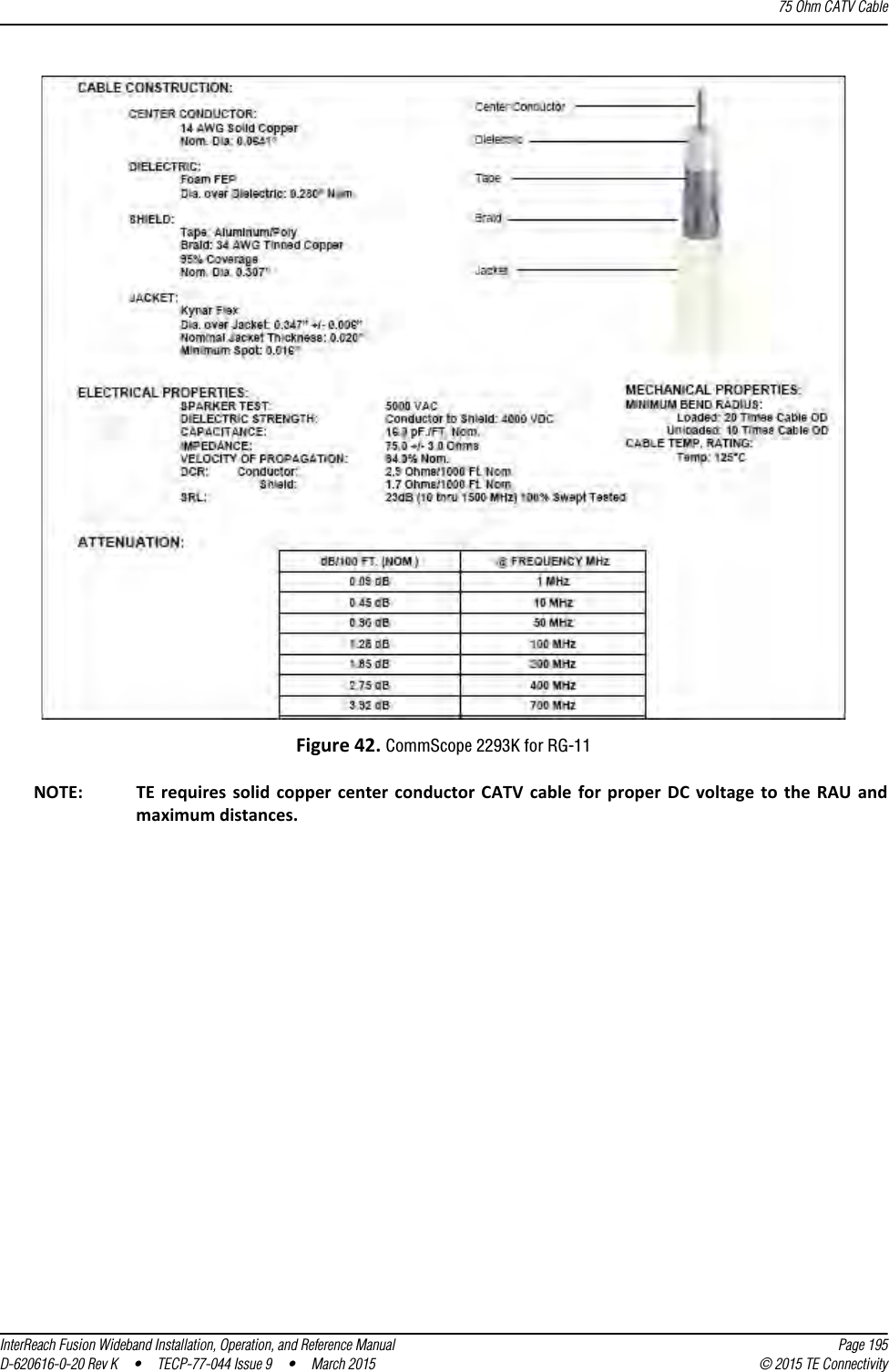
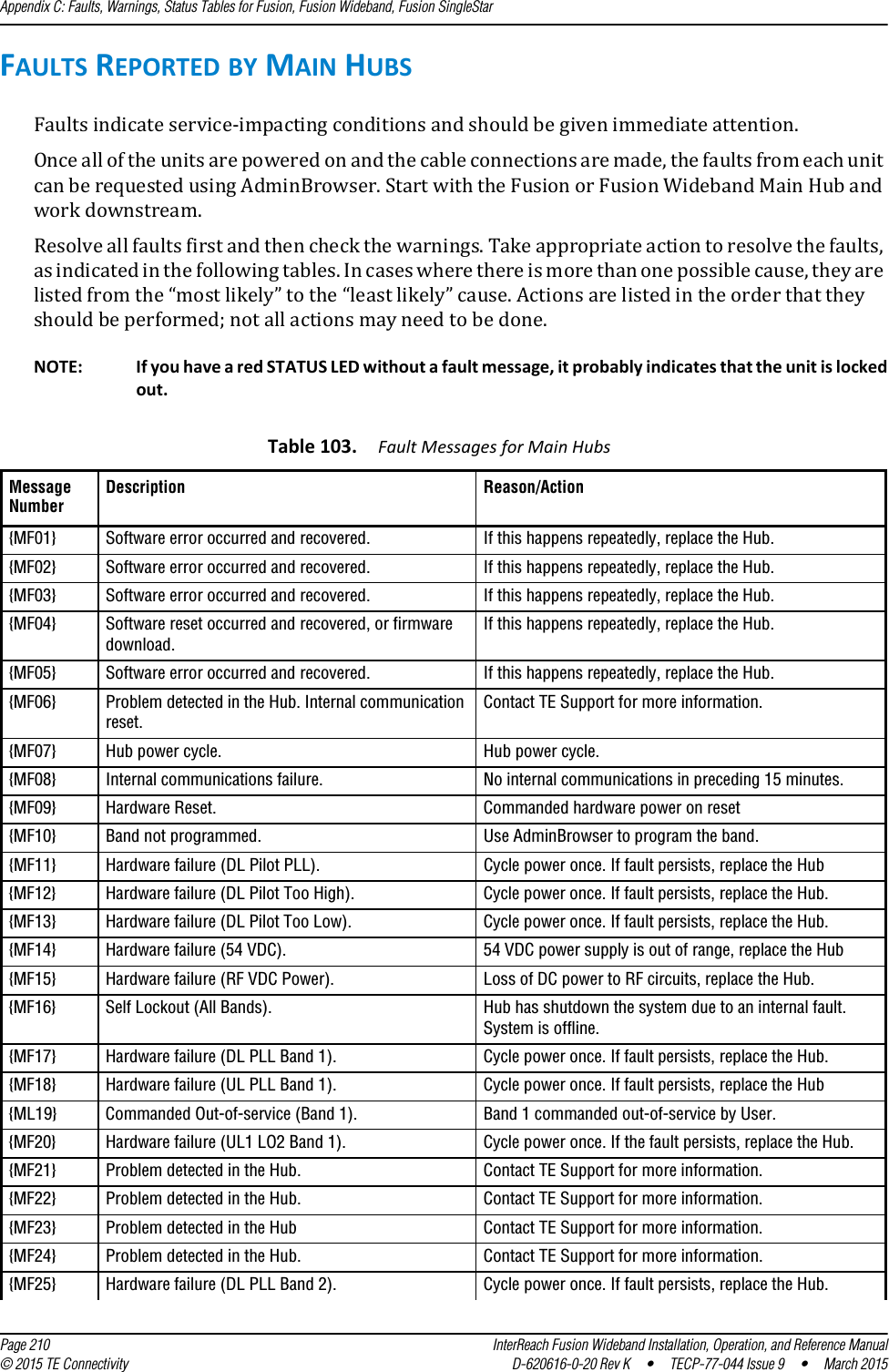
![Appendix C: Faults, Warnings, Status Tables for Fusion, Fusion Wideband, Fusion SingleStar Page 218 InterReach Fusion Wideband Installation, Operation, and Reference Manual© 2015 TE Connectivity D-620616-0-20 Rev K • TECP-77-044 Issue 9 • March 2015Table 107. Warnings/Status Messages for Main Hubs Message Number/DefaultDescription Reason/Action[M01]/S Fan 1 failure. Check the fan for rotation, air flow blockage, and dust. Replace the Hub on high temperature warning.[M02]/S Fan 2 failure. Check the fan for rotation, air flow blockage, and dust. Replace the Hub on high temperature warning.[M03]/S 54 VDC Pwr Supply Fan failure. Check the fan for rotation, air flow blockage, and dust. Replace the Hub on high temperature warning.[M04]/W 5 VDC Monitor. DC power out of range, replace the Hub.[M05]/W 9 VDC Monitor. DC power out of range, replace the Hub.[M06]/W 54 VDC Monitor. DC power out of range, replace the Hub.[M07]/W 3 VDC Monitor. DC power out of range, replace the Hub.[M08]/W 12 VDC Monitor. DC power out of range, replace the Hub.[M09]/W Temperature High. Reduce ambient temperature, check for air flow blockage, fan rotation.[M10]/W -5 VDC Monitor. DC power is out of range, replace the Hub.[M11]/W High laser current. Output laser failure possible, replace the Hub when possible.[M12]/W DL path loss is too high Replace the Hub.[M13]/S Low input optical (Port 1). Check the uplink fiber.[M14]/S Low input optical (Port 2). Check the uplink fiber.[M15]/S Low input optical (Port 3). Check the uplink fiber.[M16]/S Low input optical (Port 4). Check the uplink fiber.[M17]/S Hardware failure (Test Tone PLL Band 1). Unable to perform DL system test.[M18]/S Hardware failure (Test Tone Too High Band 1). Unable to perform DL system test.[M19]/S Hardware failure (Test Tone Too Low Band 1). Unable to perform DL system test.[M20]/W Overdrive limiter active (Band 1). Reduce input signal power to avoid potential component damage.[M21]/W CEMark limiter at maximum (Band 1). Reduce input signal power to avoid drop in system gain.[M22]/W No DL test tone (Band 1). Hub DL gain is low.[M23]/S No UL test tone (Band 1). Hub UL path gain is low.[M24]/S Problem detected in the system. Contact TE Support for more information.[M25]/S Hardware failure (Test Tone PLL Band 2). Unable to perform DL system test. Replace the hub when possible.[M26]/S Hardware failure (Test Tone Too High Band 2). Unable to perform DL system test. Replace the hub when possible.[M27]/S Hardware failure (Test Tone Too Low Band 2). Unable to perform DL system test. Replace the hub when possible.[M28]/W Overdrive limiter active (Band 2). Reduce input signal power to avoid potential component damage.[M29]/W CEMark limiter at maximum (Band 2). Reduce input signal power to avoid drop in system gain.[M30]/W No DL test tone (Band 2). Hub DL path gain is low.[M31]/S No UL test tone (Band 2). Hub UL path gain is low.[M32]/S Problem detected in the system. Contact TE Support for more information.[M33]/S Hardware failure (Test Tone PLL Band 3). Unable to perform DL system test.[M34]/S Hardware failure (Test Tone Too High Band 3). Unable to perform DL system test.[M35]/S Hardware failure (Test Tone Too Low Band 3). Unable to perform DL system test.[M36]/W Overdrive limiter active (Band 3). Reduce input signal power to avoid potential component damage.](https://usermanual.wiki/ADC-Telecommunications/F0851-111/User-Guide-2572832-Page-226.png)
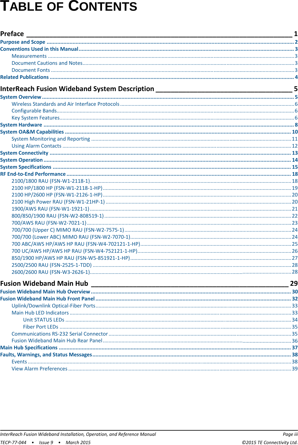
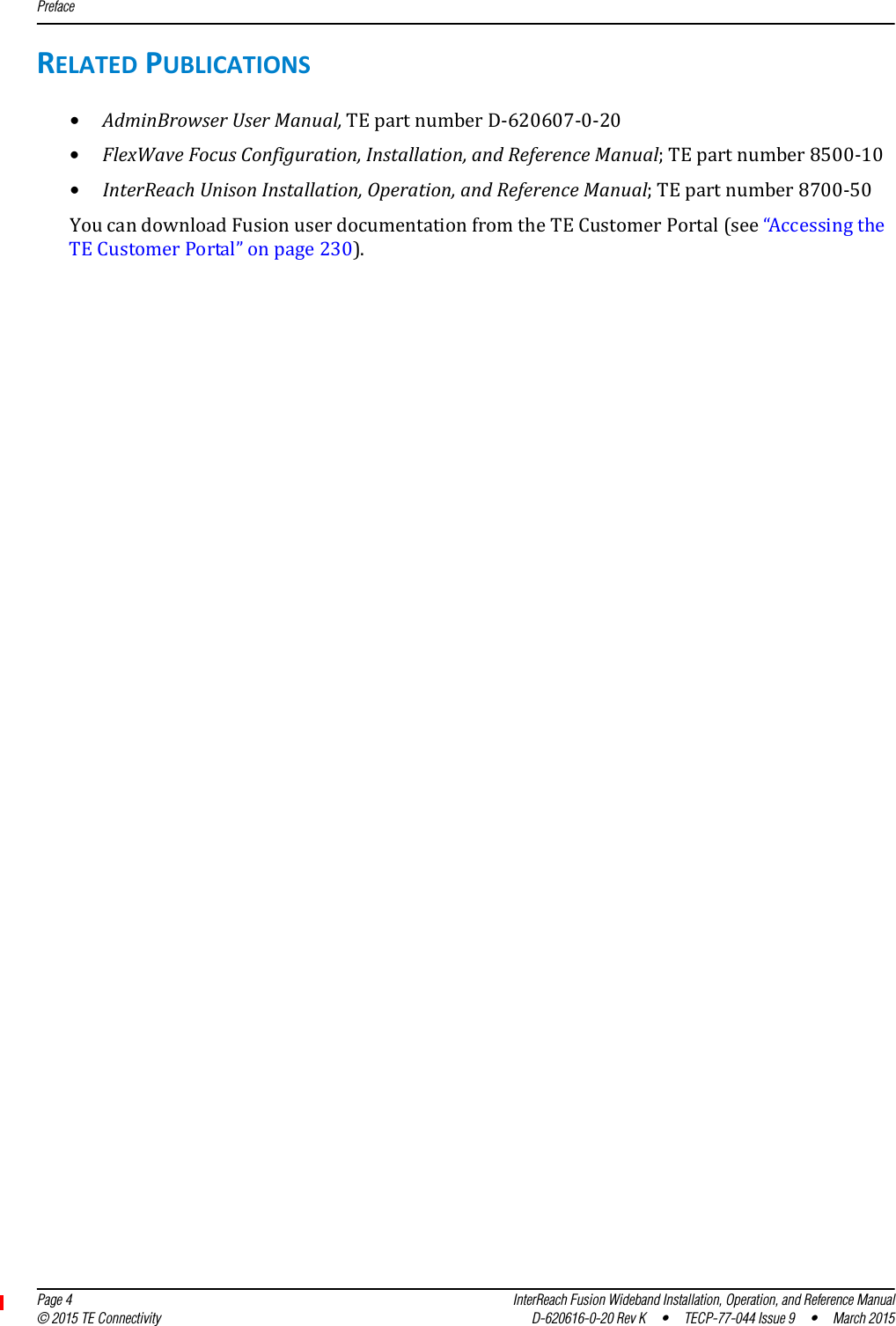
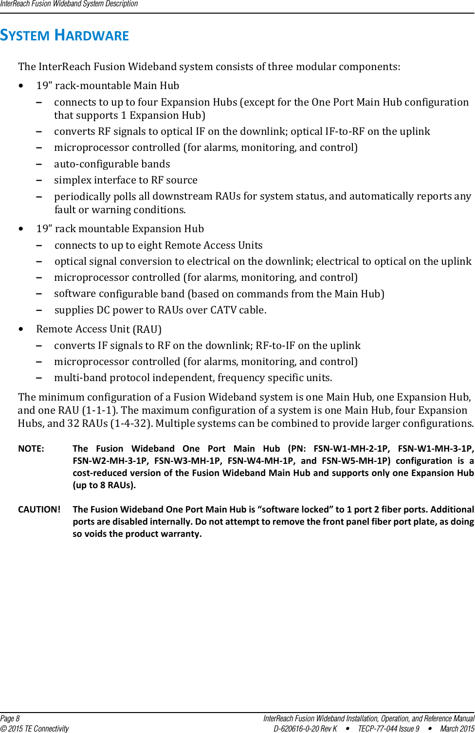
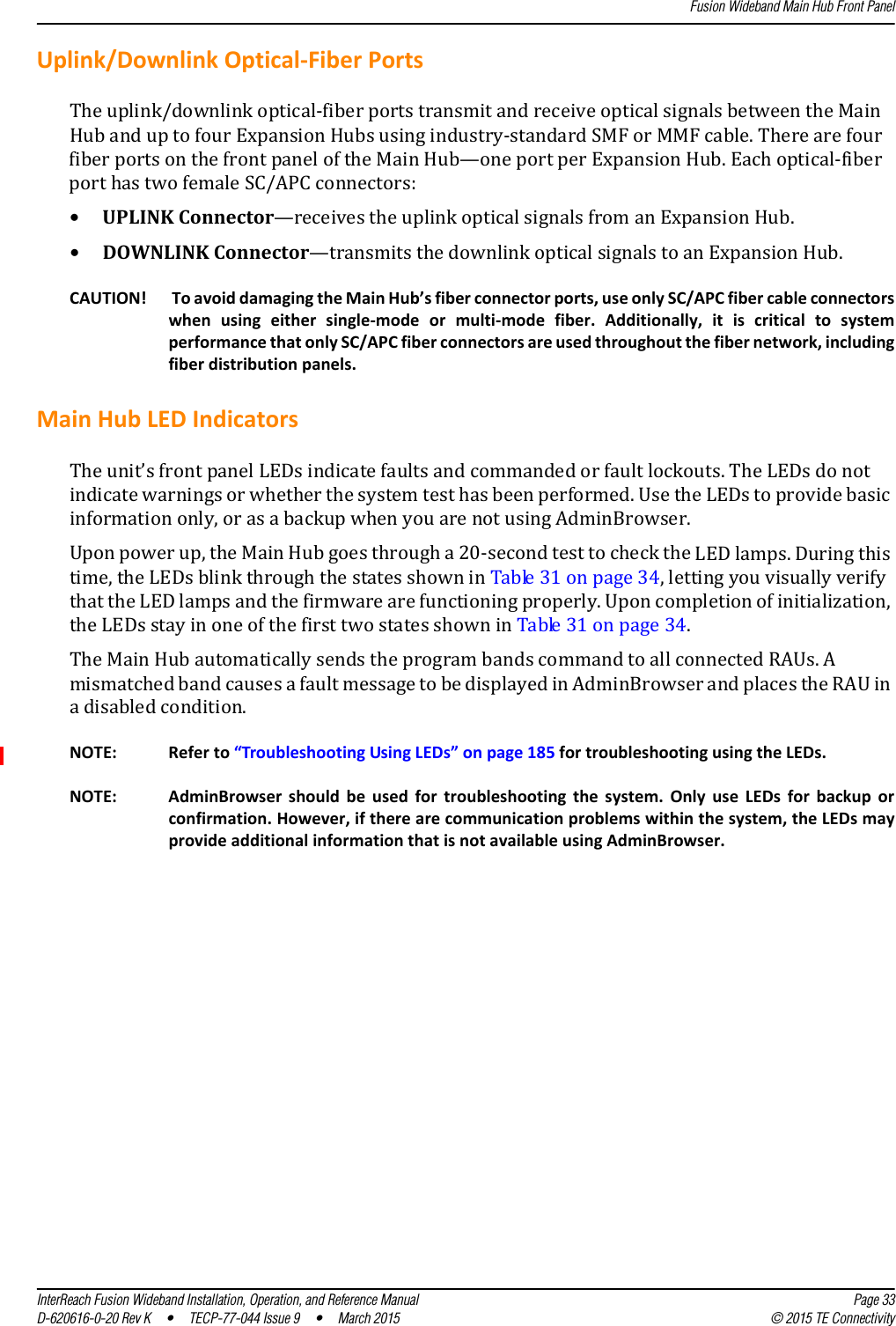
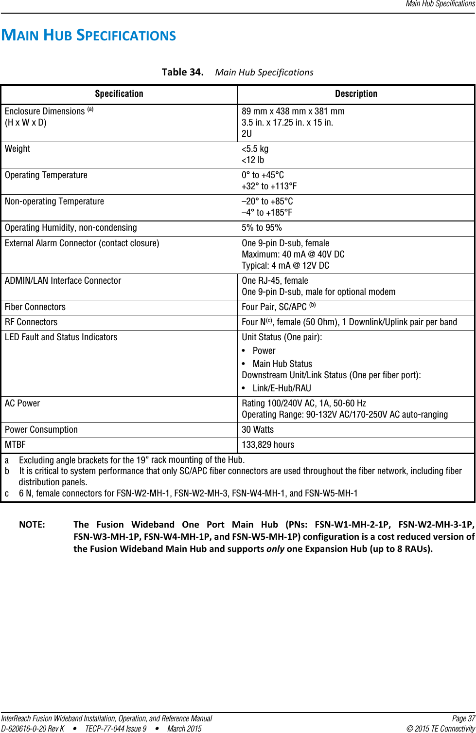
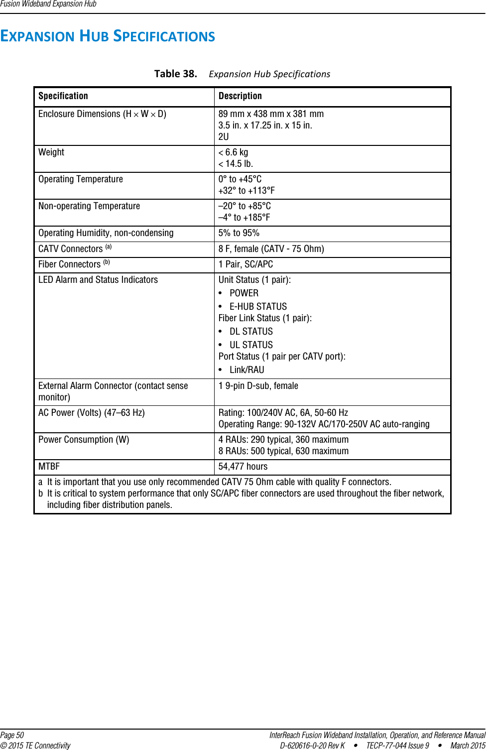
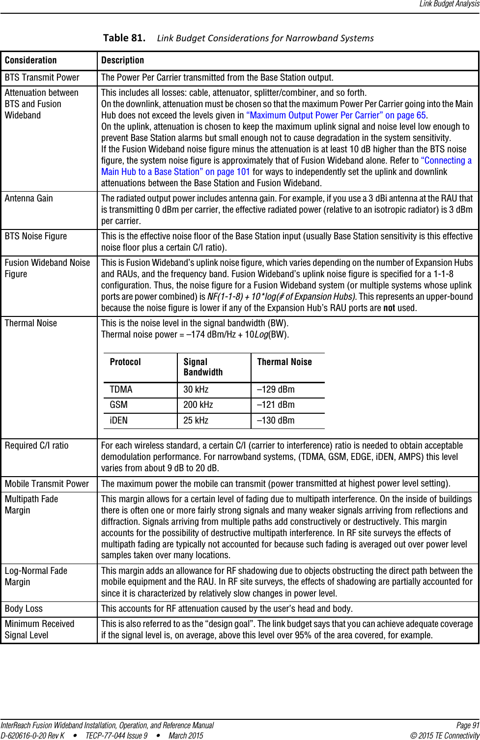
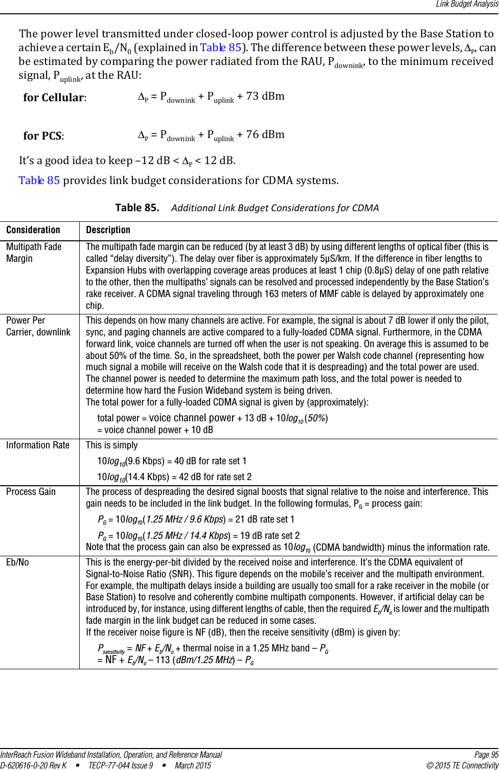
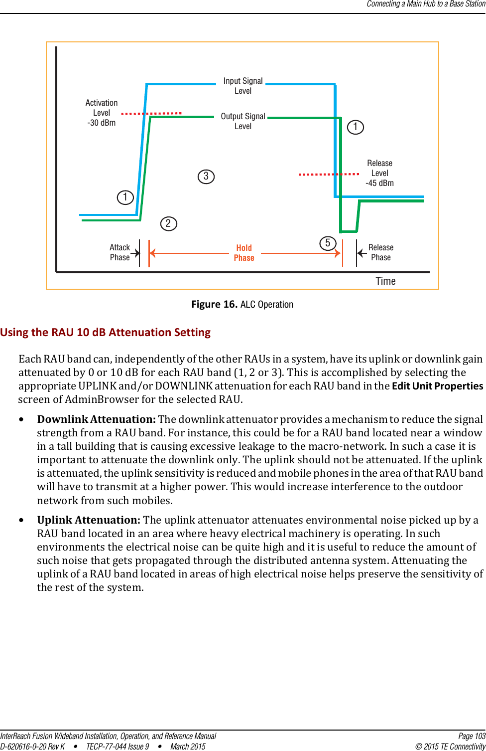
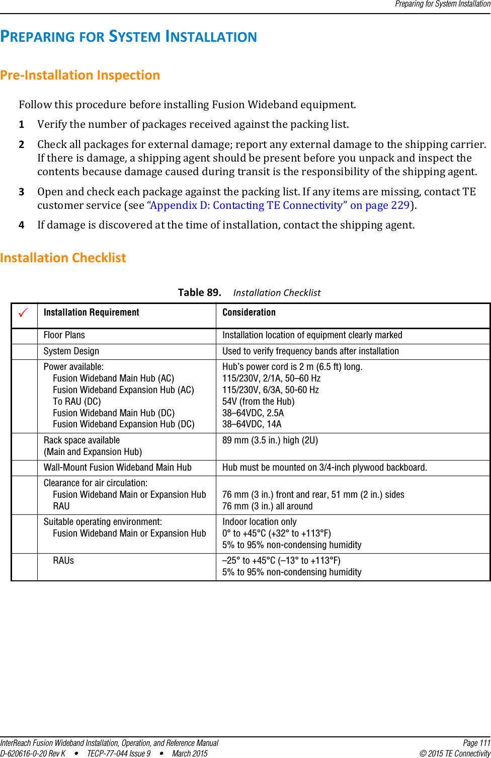
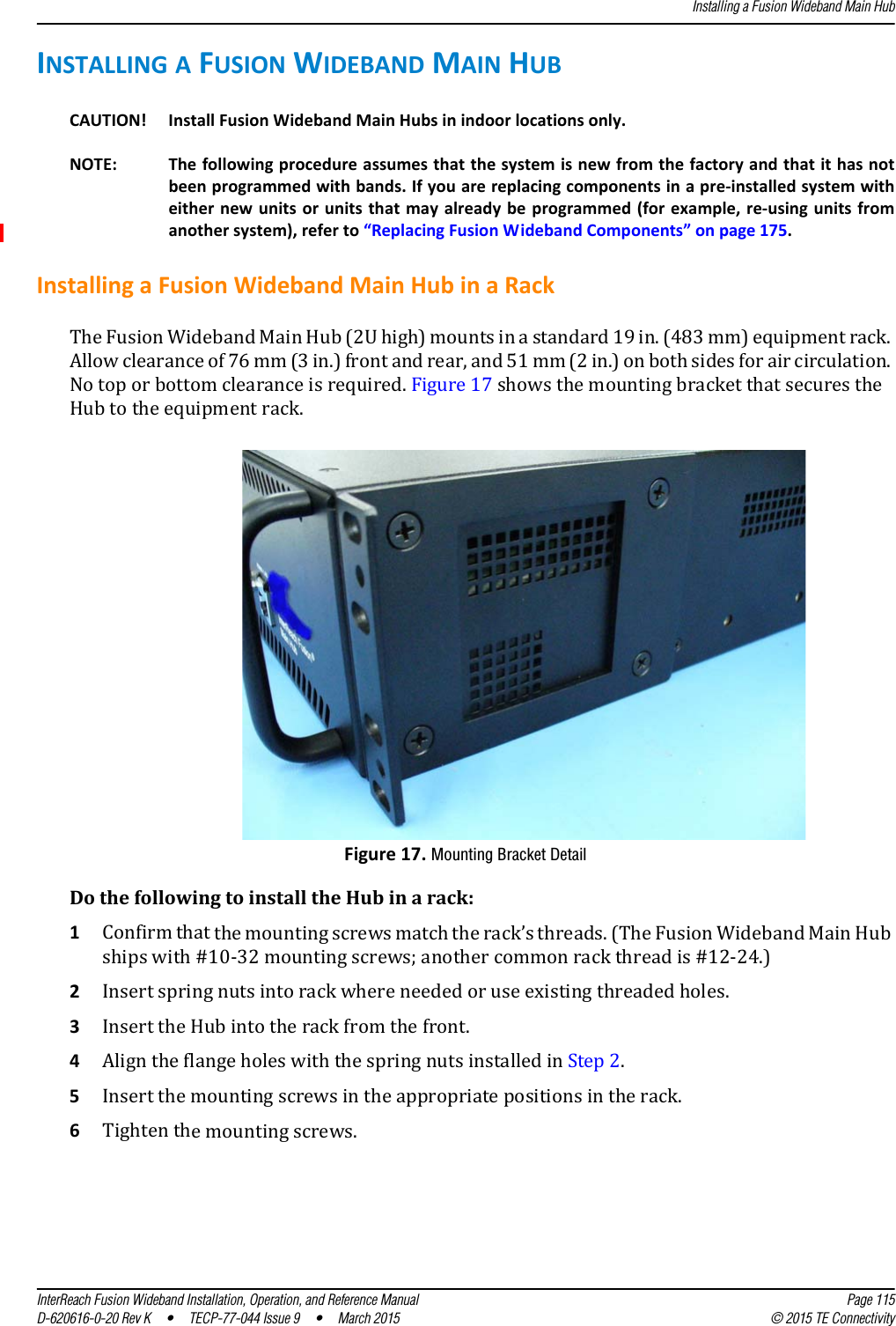
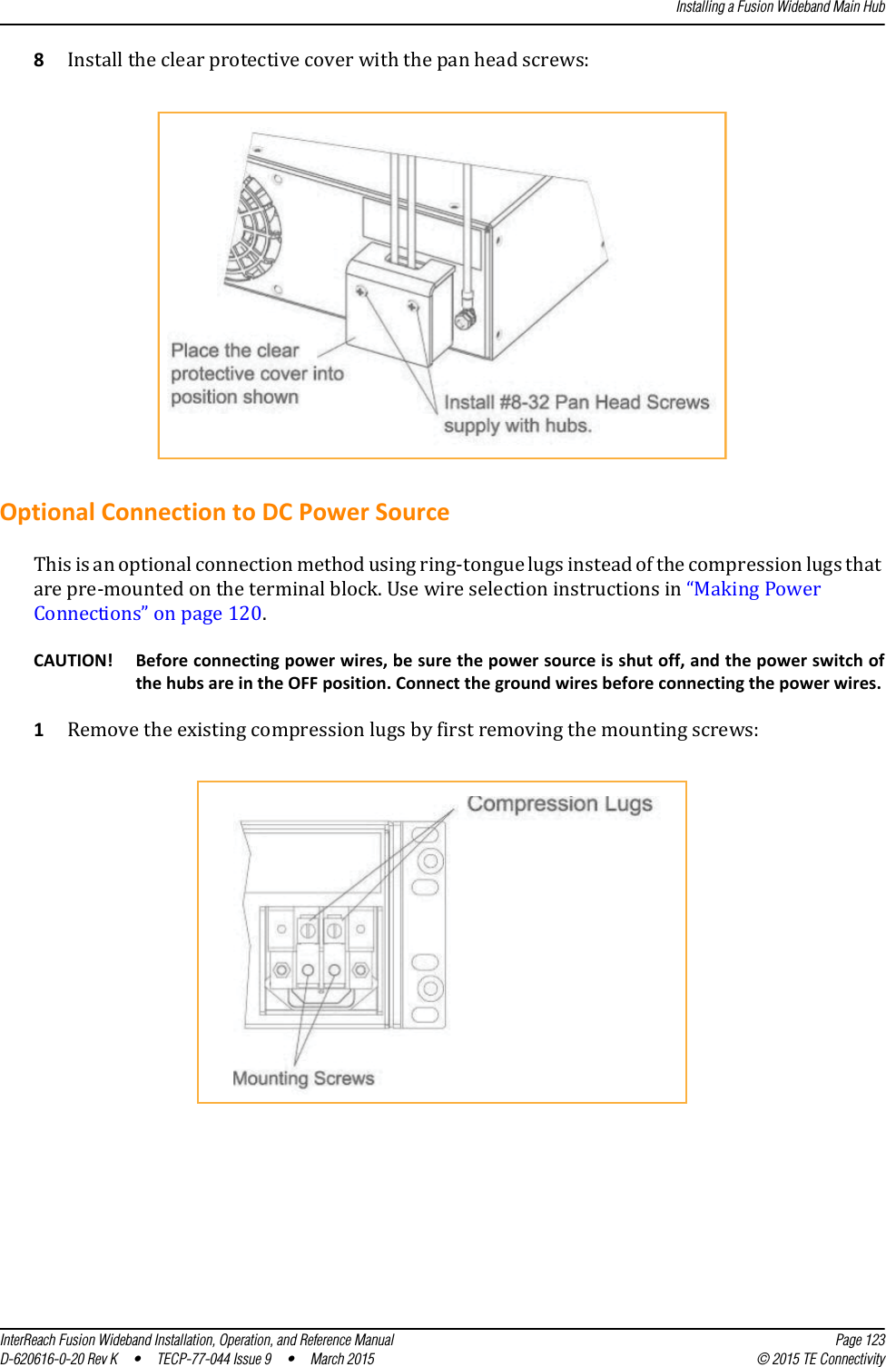
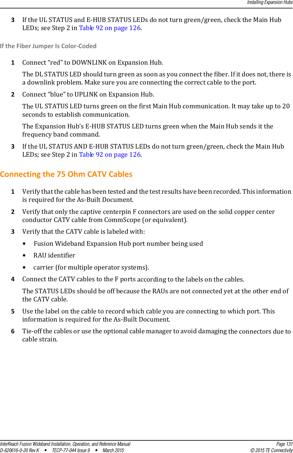
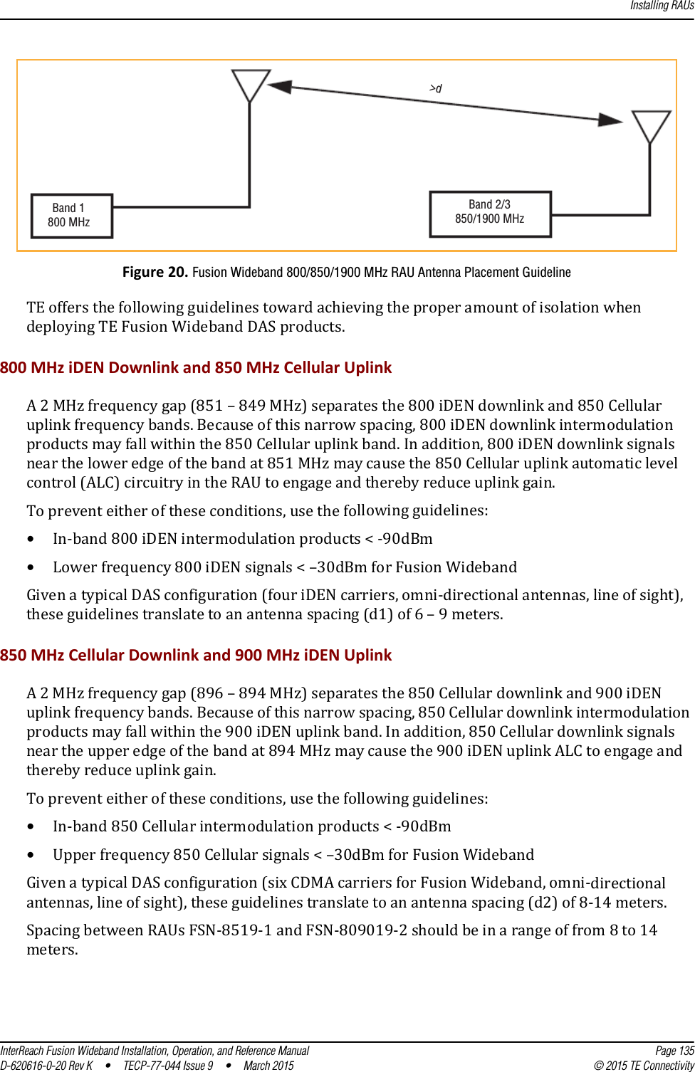
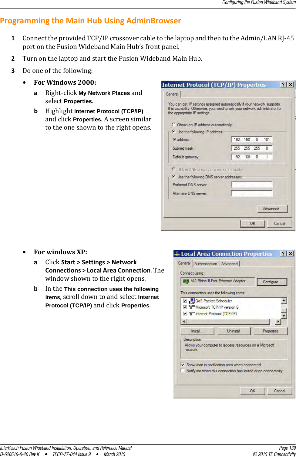
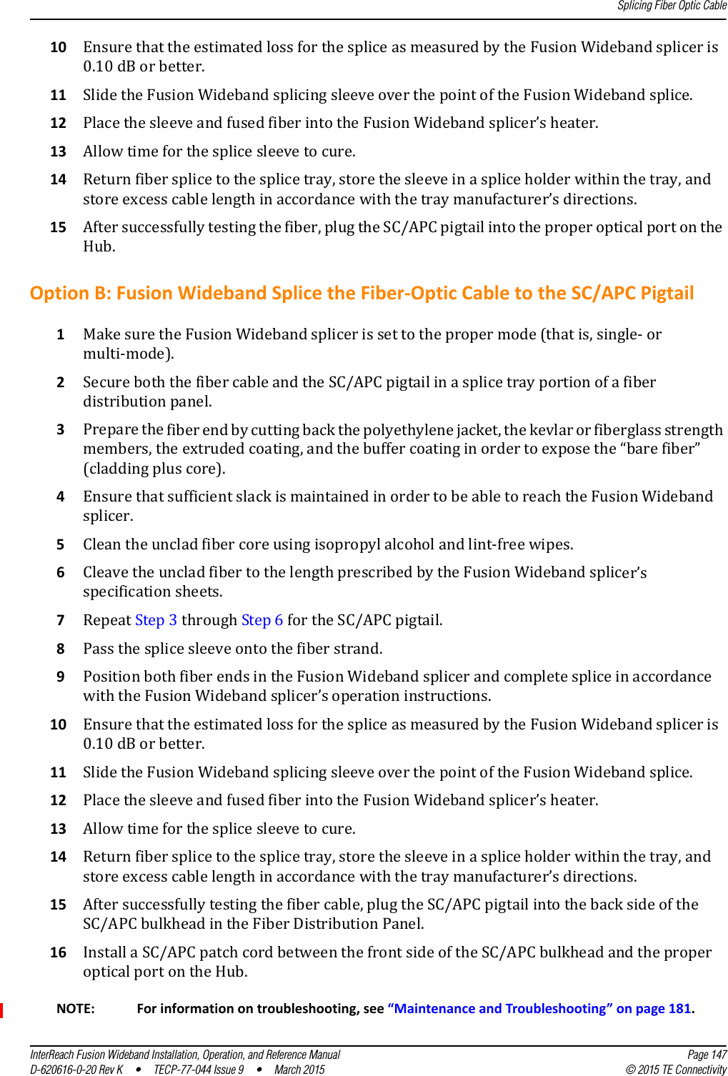
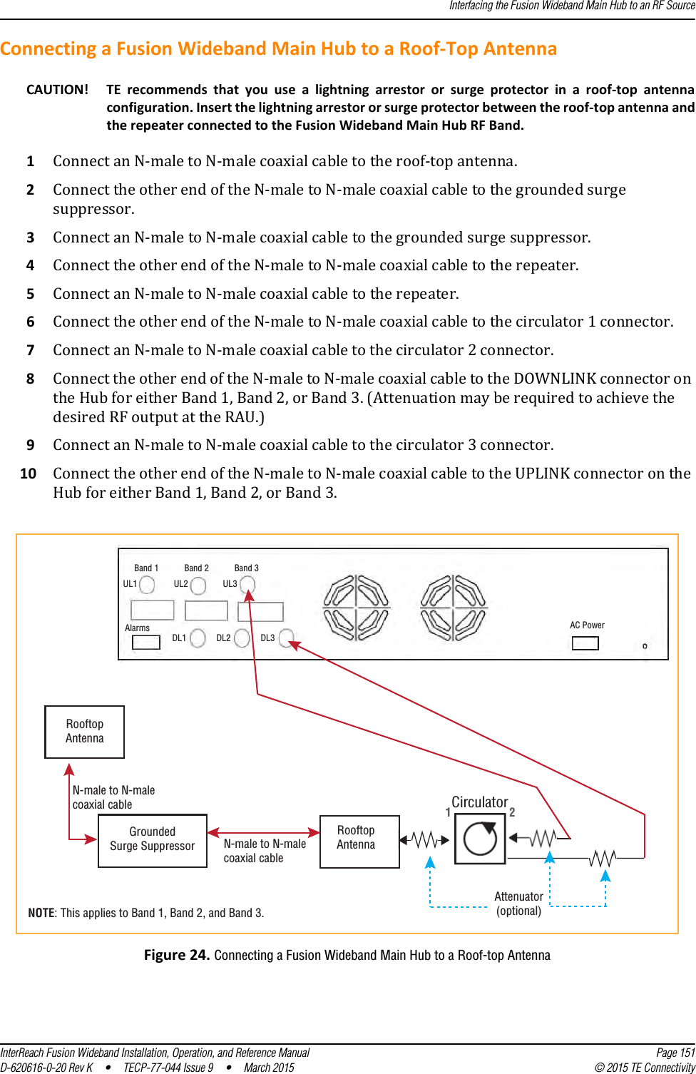
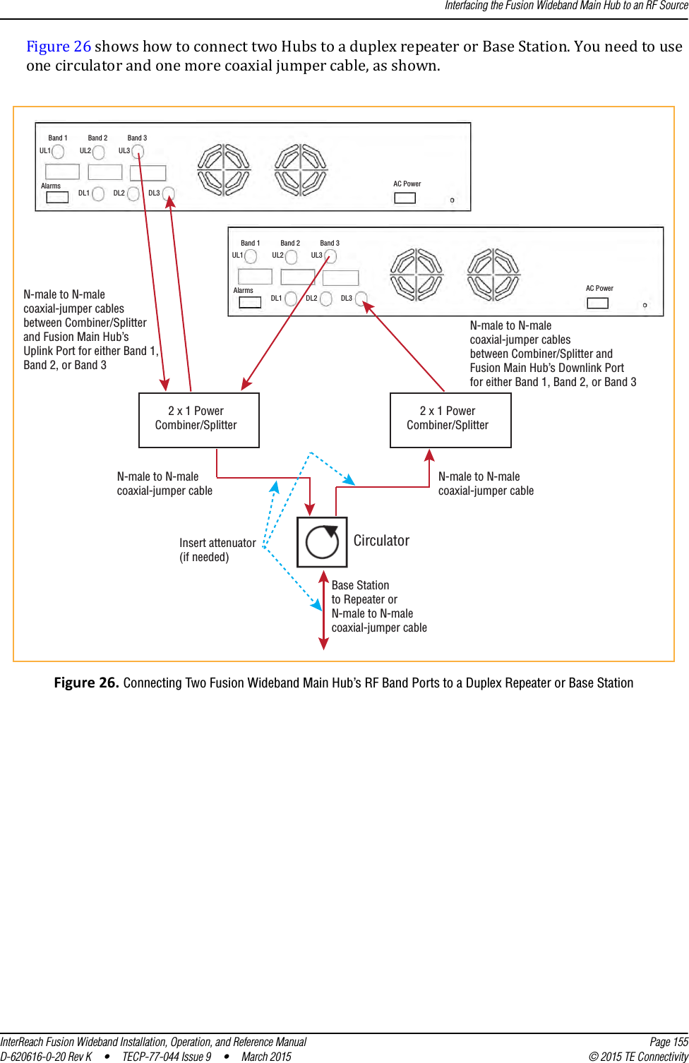
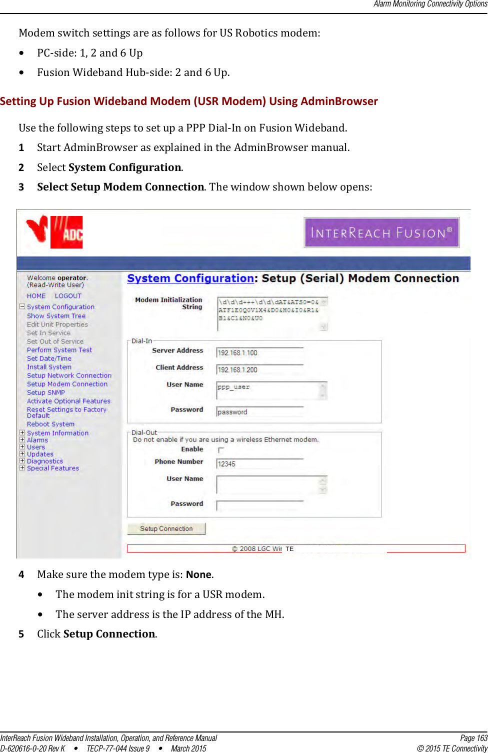
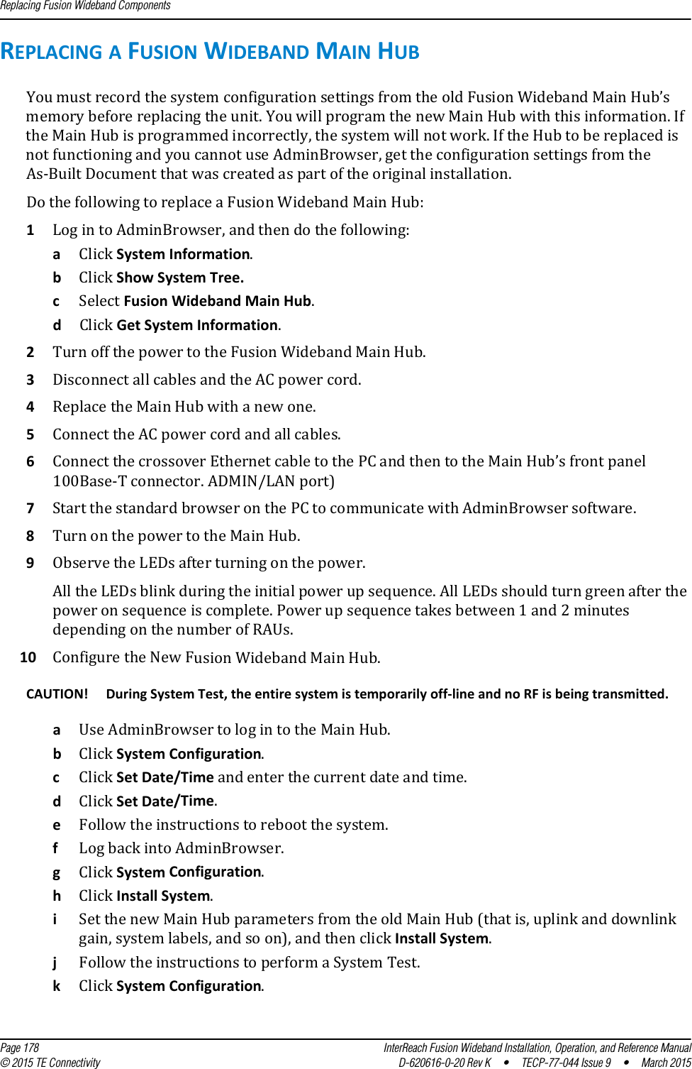
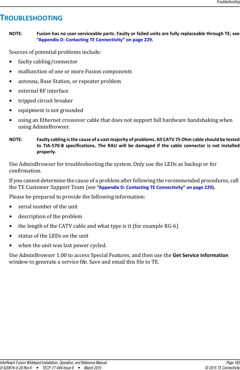
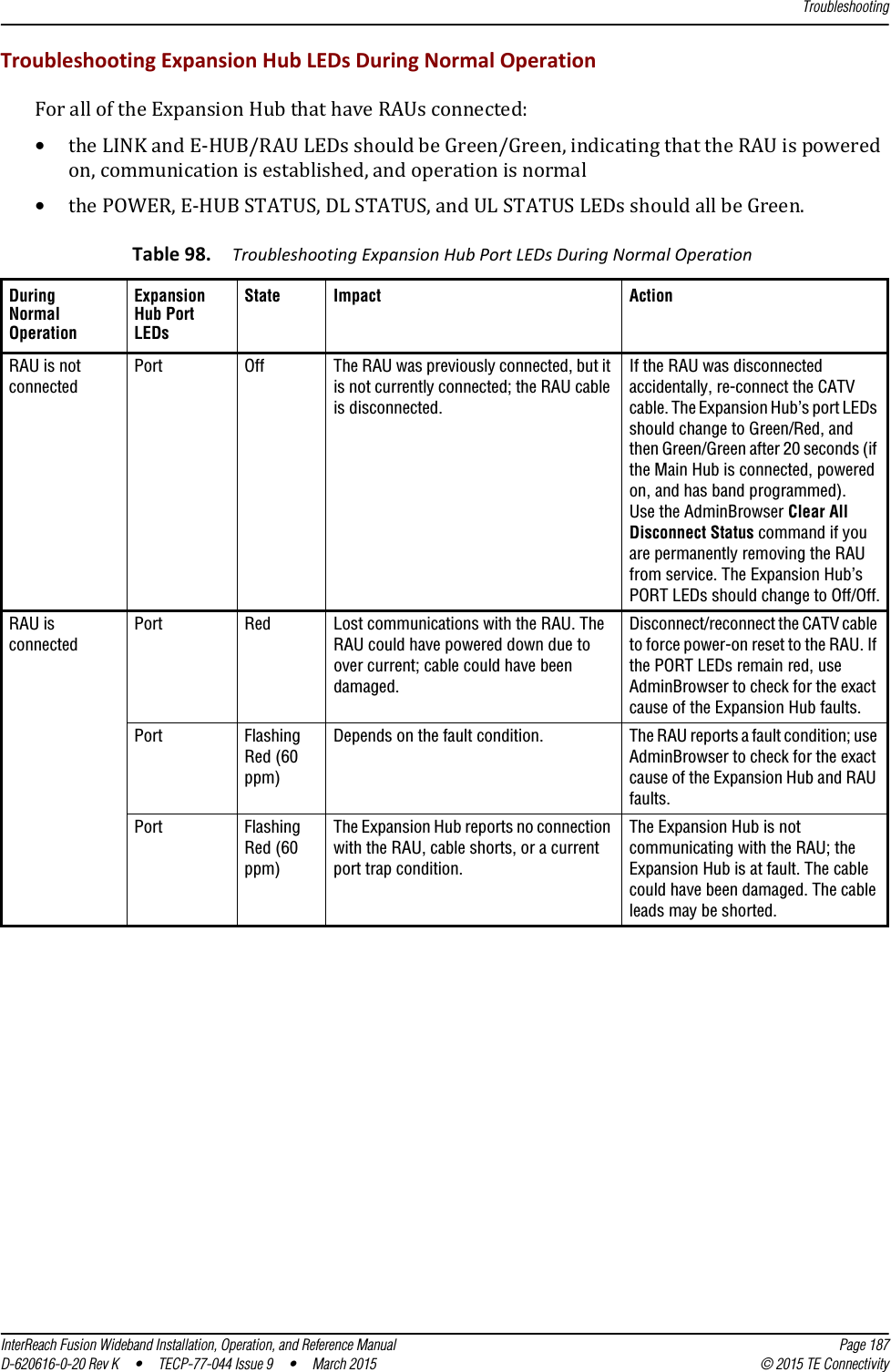
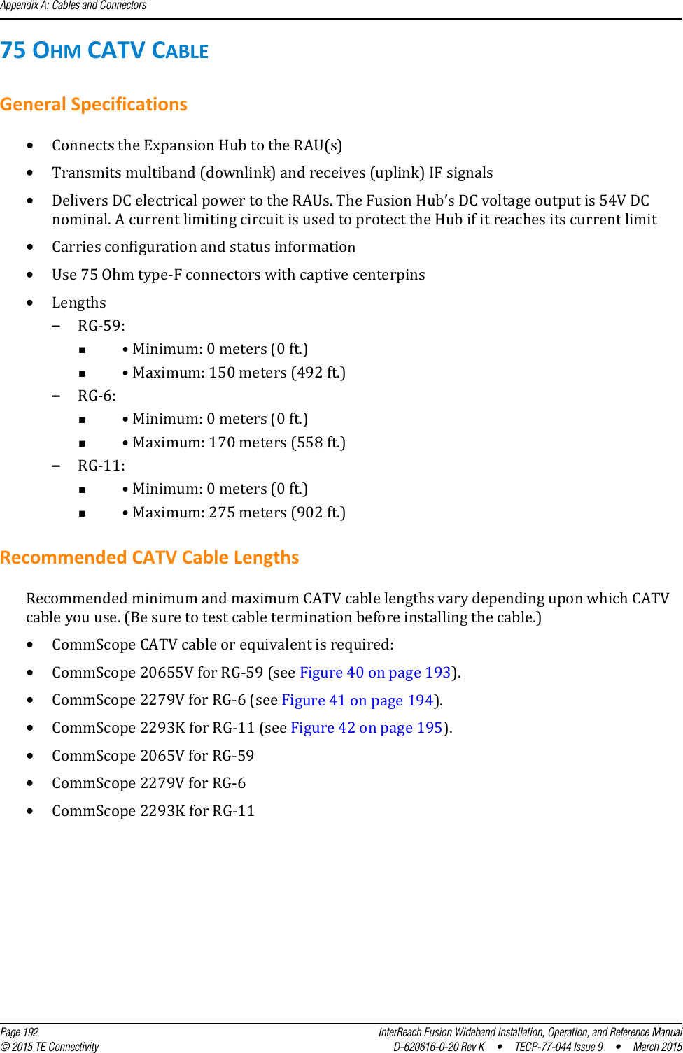
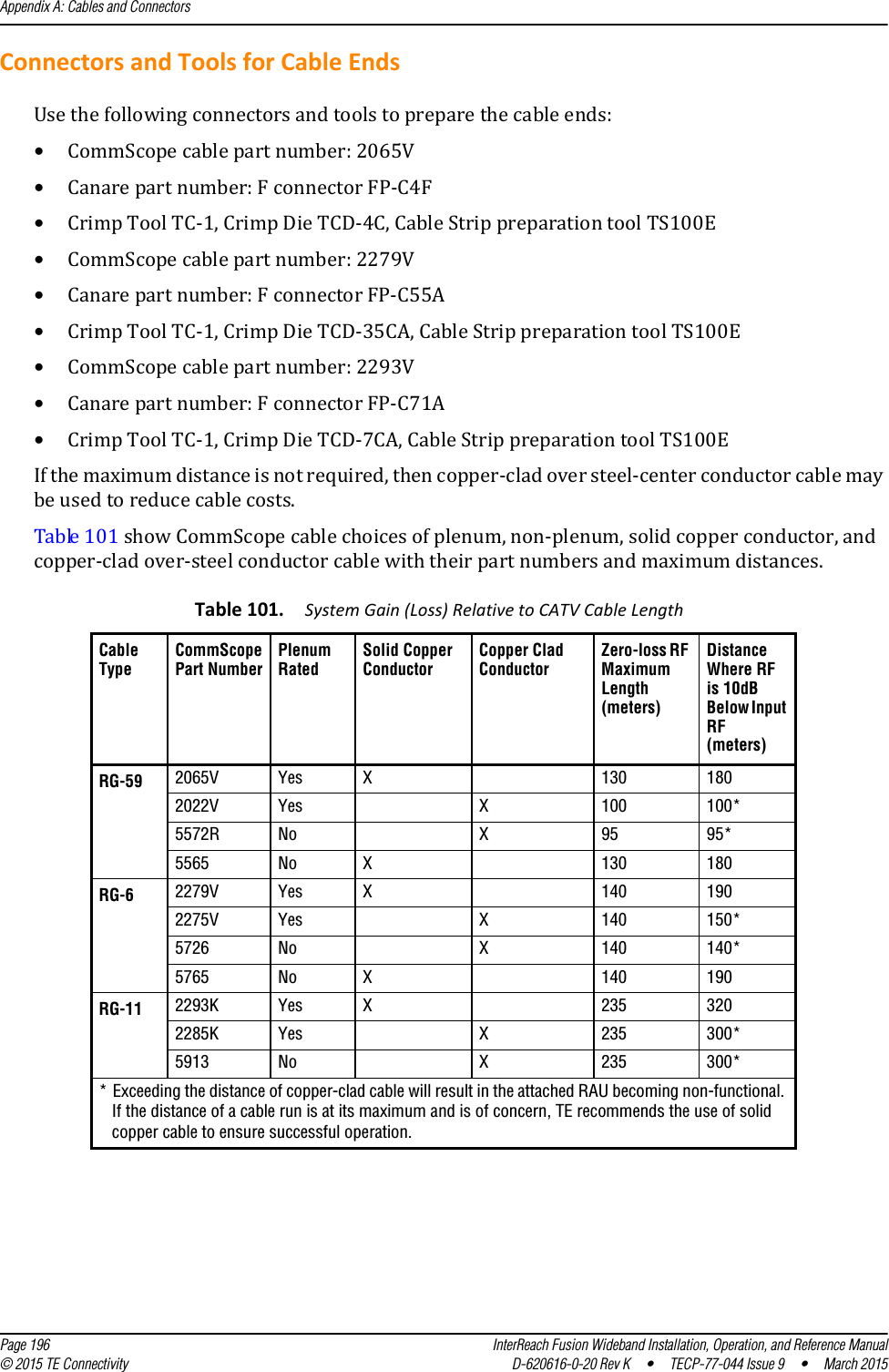
![Messages for Main HubsInterReach Fusion Wideband Installation, Operation, and Reference Manual Page 219D-620616-0-20 Rev K • TECP-77-044 Issue 9 • March 2015 © 2015 TE Connectivity[M37]/W CEMark limiter at maximum (Band 3). Reduce input signal power to avoid drop in system gain.[M38]/W No DL test tone (Band 3). Hub DL path gain is low.[M39]/S No UL test tone (Band 3). Hub UL path gain is low.[M40]/S Problem detected in the Hub. Contact TE Support for more information.[M41]/W Port 1 No DL test tone (Band 1). Hub/Port DL path gain is low.[M42]/W Port 2 No DL test tone (Band 1). Hub/Port DL path gain is low.[M43]/W Port 3 No DL test tone (Band 1). Hub/Port DL path gain is low.[M44]/W Port 4 No DL test tone (Band 1). Hub/Port DL path gain is low.[M45]/W Port 5 No DL test tone (Band 1). Hub/Port DL path gain is low.[M46]/W Port 6 No DL test tone (Band 1). Hub/Port DL path gain is low.[M47]/W Port 7 No DL test tone (Band 1). Hub/Port DL path gain is low.[M48]/W Port 8 No DL test tone (Band 1). Hub/Port DL path gain is low.[M49]/W Port 1 No DL test tone (Band 2). Hub/Port DL path gain is low.[M50]/W Port 2 No DL test tone (Band 2). Hub/Port DL path gain is low.[M51]/W Port 3 No DL test tone (Band 2). Hub/Port DL path gain is low.[M52]/W Port 4 No DL test tone (Band 2). Hub/Port DL path gain is low.[M53]/W Port 5 No DL test tone (Band 2). Hub/Port DL path gain is low.[M54]/W Port 6 No DL test tone (Band 2). Hub/Port DL path gain is low.[M55]/W Port 7 No DL test tone (Band 2). Hub/Port DL path gain is low.[M56]/W Port 8 No DL test tone (Band 2). Hub/Port DL path gain is low.[M57]/W Port 1 No DL test tone (Band 3). Hub/Port DL path gain is low.[M58]/W Port 2 No DL test tone (Band 3). Hub/Port DL path gain is low.[M59]/W Port 3 No DL test tone (Band 3). Hub/Port DL path gain is low.[M60]/W Port 4 No DL test tone (Band 3). Hub/Port DL path gain is low.[M61]/W Port 5 No DL test tone (Band 3). Hub/Port DL path gain is low.[M62]/W Port 6 No DL test tone (Band 3). Hub/Port DL path gain is low.[M63]/W Port 7 No DL test tone (Band 3). Hub/Port DL path gain is low.[M64]/W Port 8 No DL test tone (Band 3). Hub/Port DL path gain is low.[M65]/S No UL test tone Port 1 (Band 1). Hub/Port UL path gain is low.[M66]/S No UL test tone Port 2 (Band 1). Hub/Port UL path gain is low.[M67]/S No UL test tone Port 3 (Band 1). Hub/Port UL path gain is low.[M68]/S No UL test tone Port 4 (Band 1). Hub/Port UL path gain is low.[M69]/S No UL test tone Port 1 (Band 2). Hub/Port UL path gain is low.[M70]/S No UL test tone Port 2 (Band 2). Hub/Port UL path gain is low.[M71]/S No UL test tone Port 3 (Band 2). Hub/Port UL path gain is low.[M72]/S No UL test tone Port 4 (Band 2). Hub/Port UL path gain is low.[M73]/S No UL test tone Port 1 (Band 3). Hub/Port UL path gain is low.[M74]/S No UL test tone Port 2 (Band 3). Hub/Port UL path gain is low.[M75]/S No UL test tone Port 3 (Band 3). Hub/Port UL path gain is low.Table 107. Warnings/Status Messages for Main Hubs (Cont.)Message Number/DefaultDescription Reason/Action](https://usermanual.wiki/ADC-Telecommunications/F0851-111/User-Guide-2572832-Page-227.png)
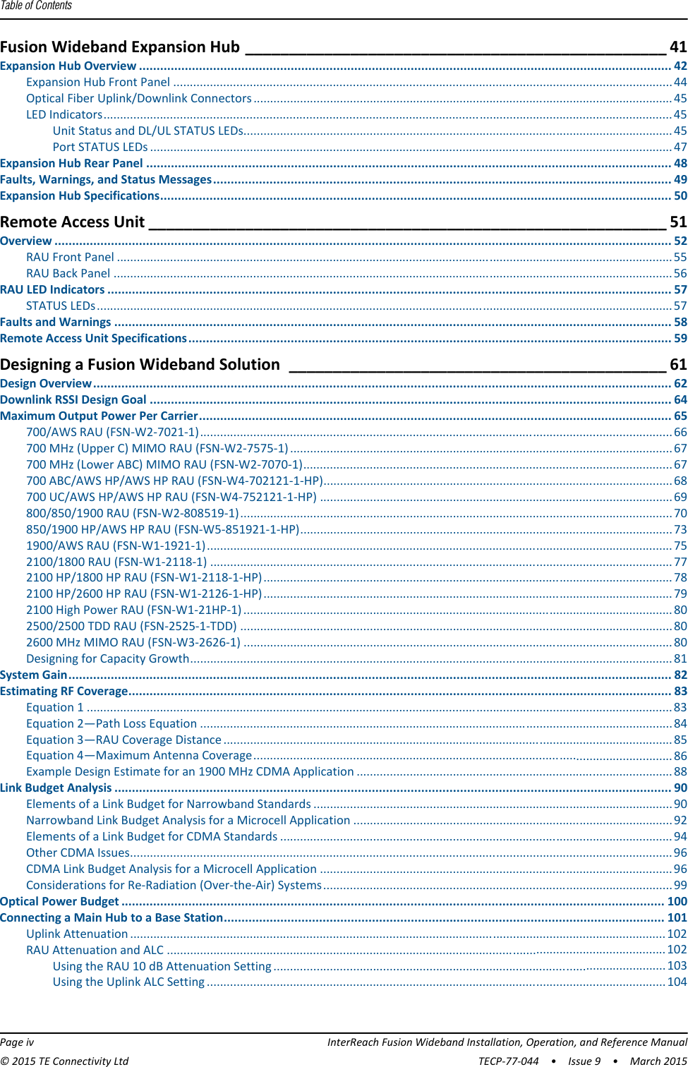
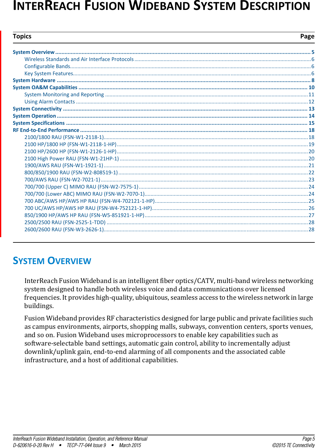
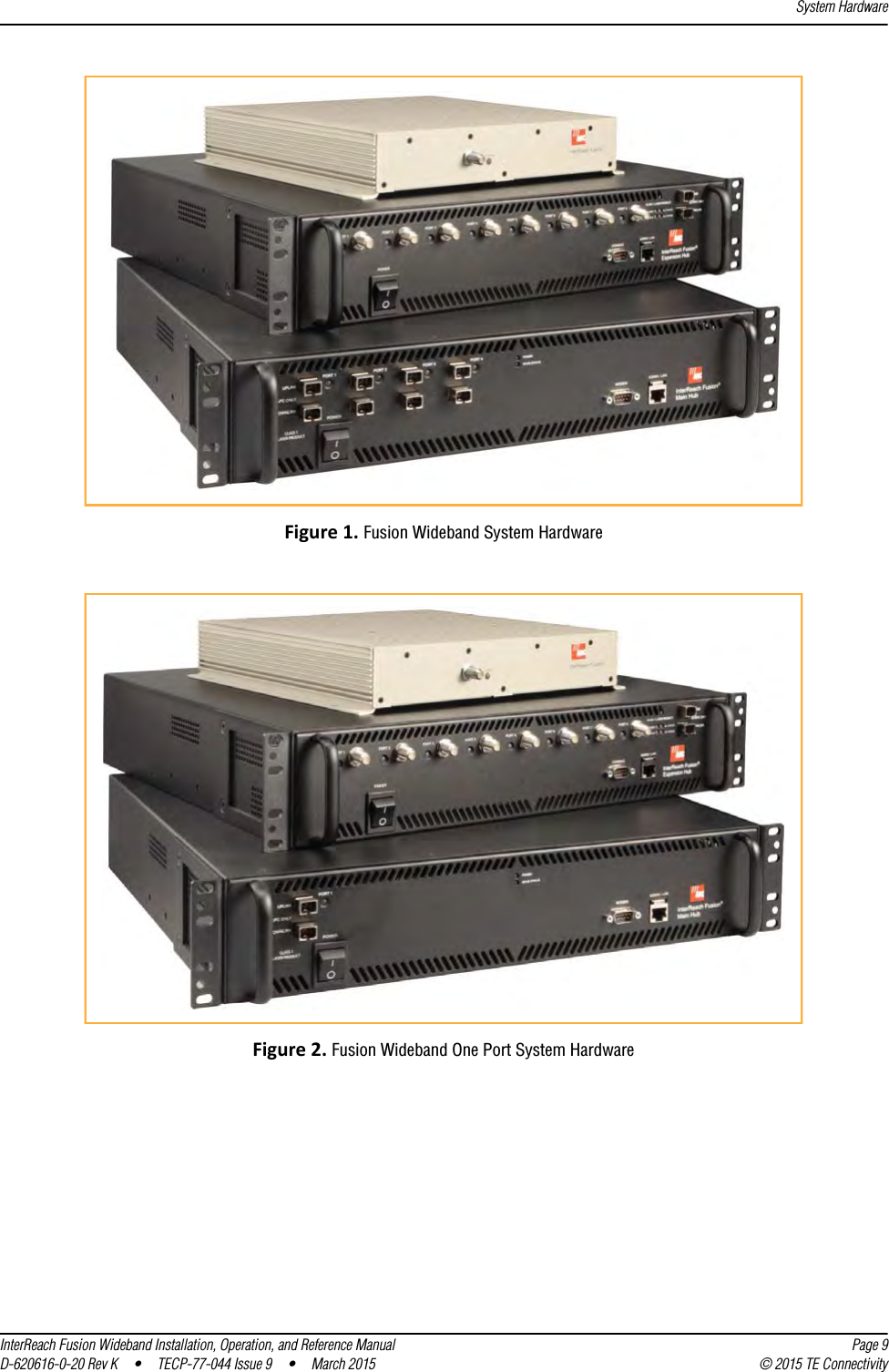
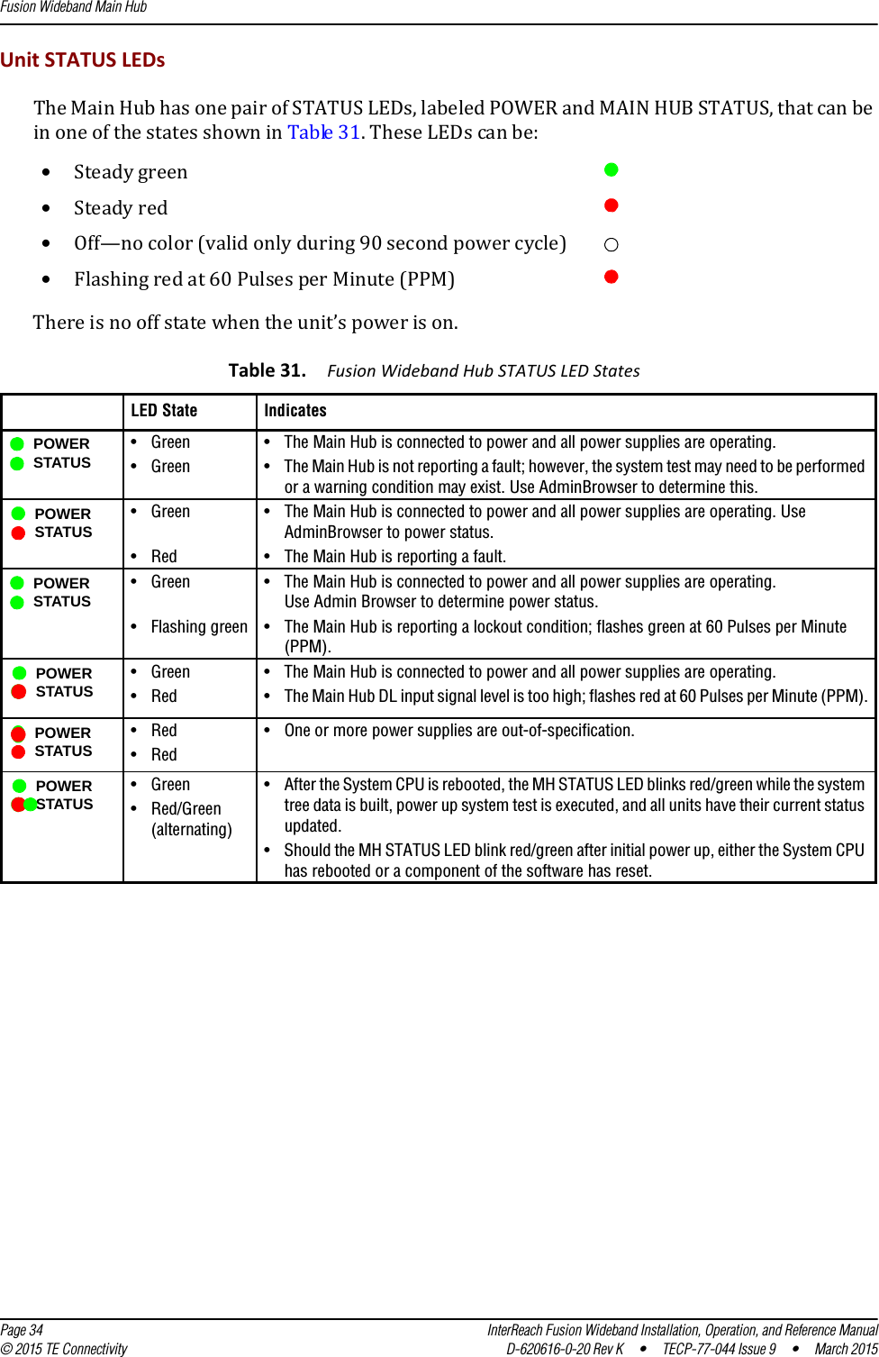
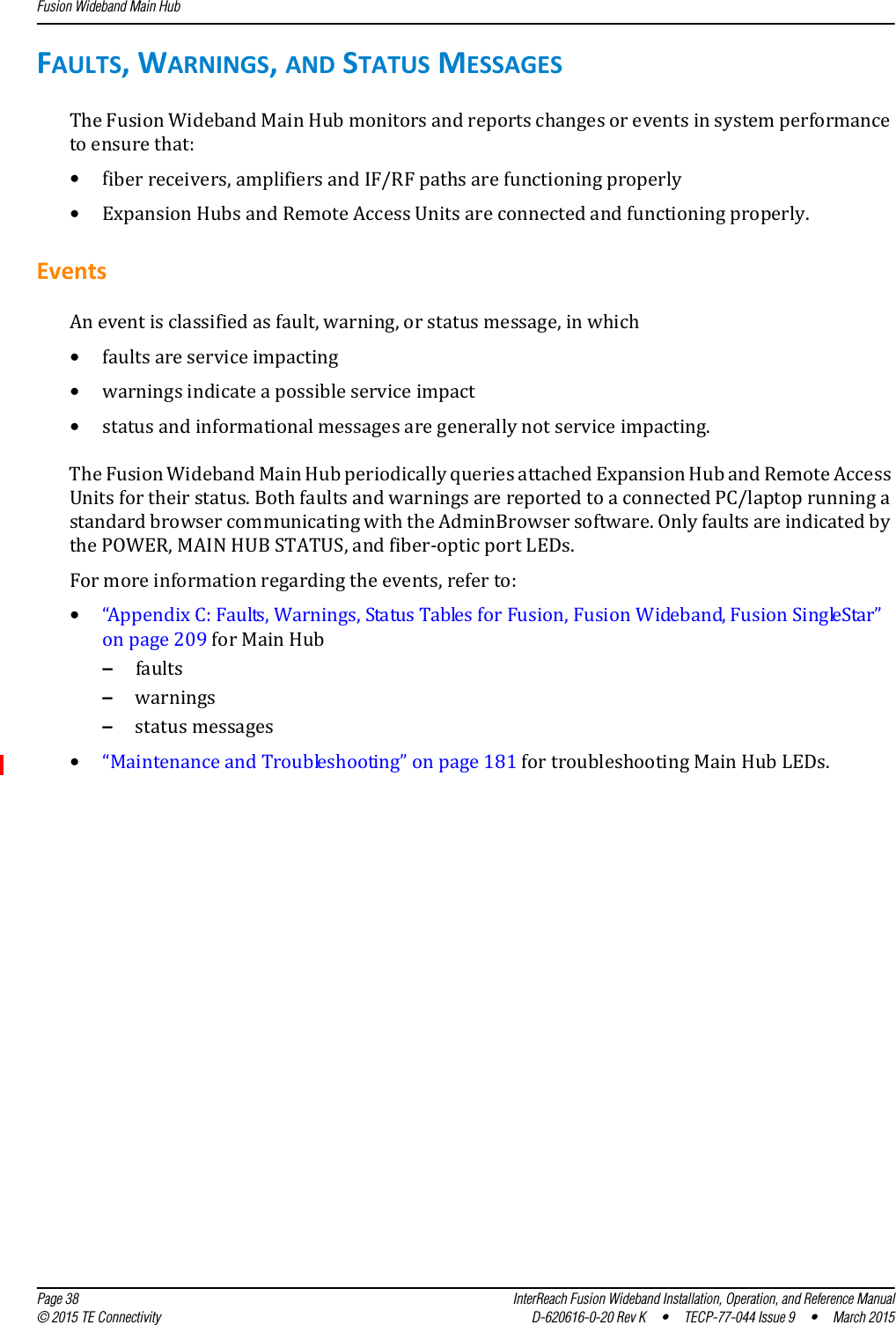
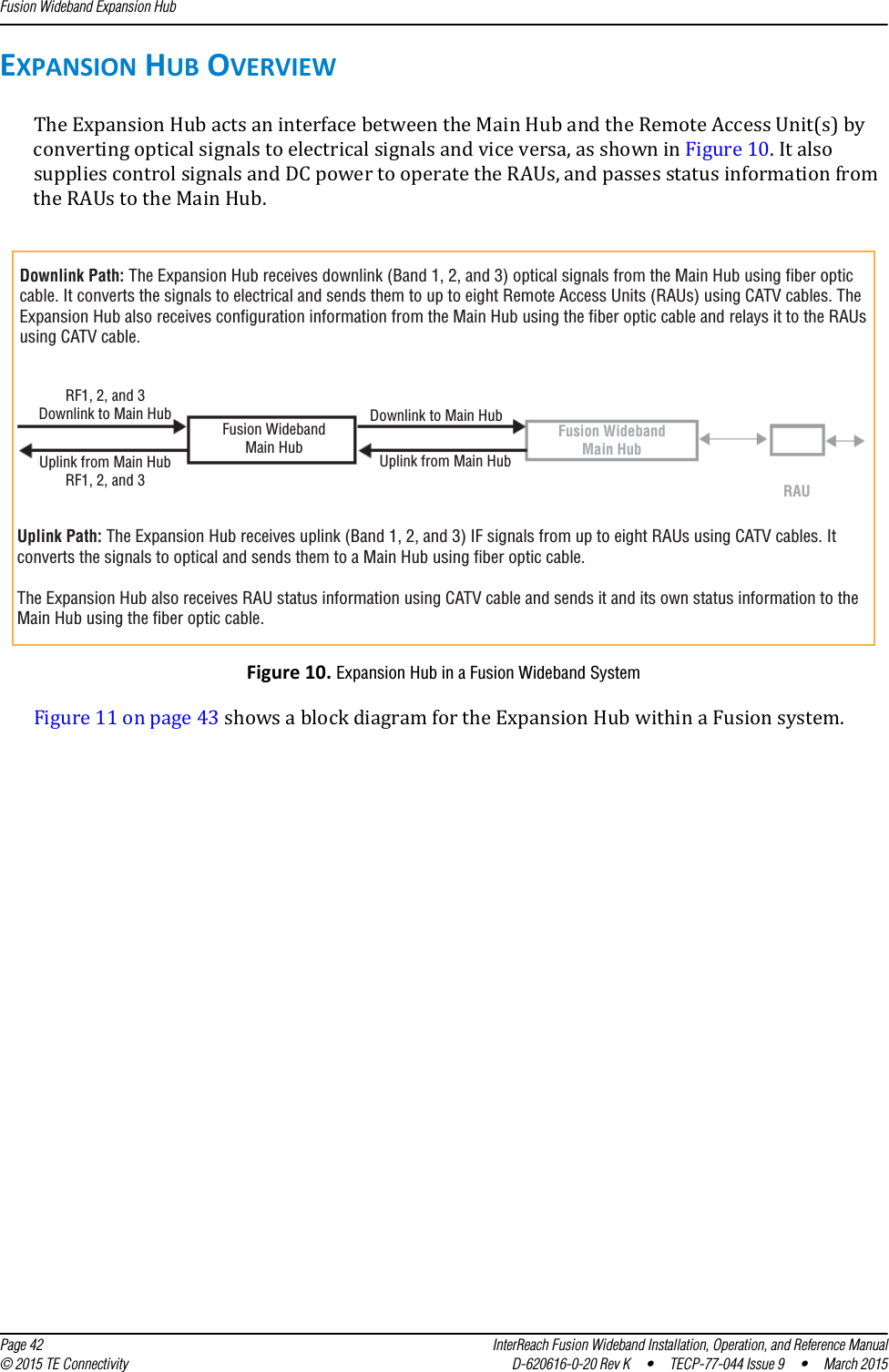
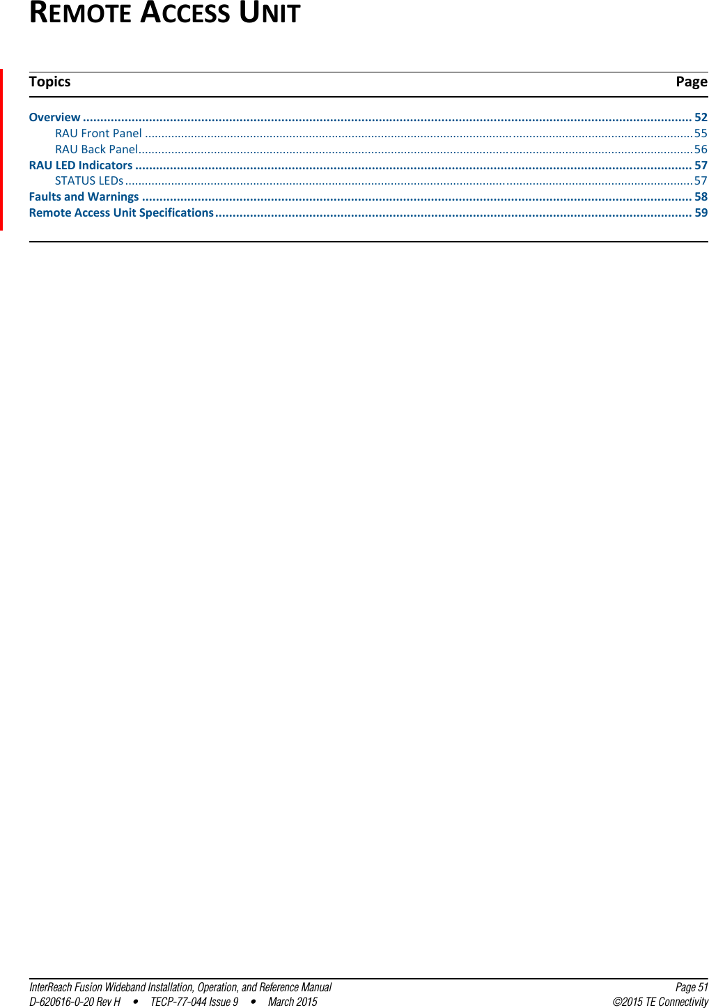
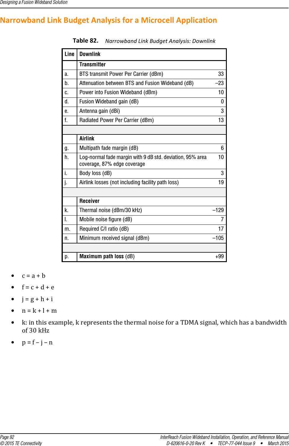
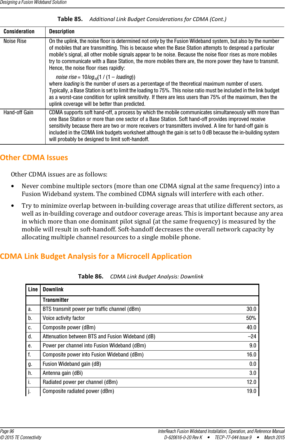
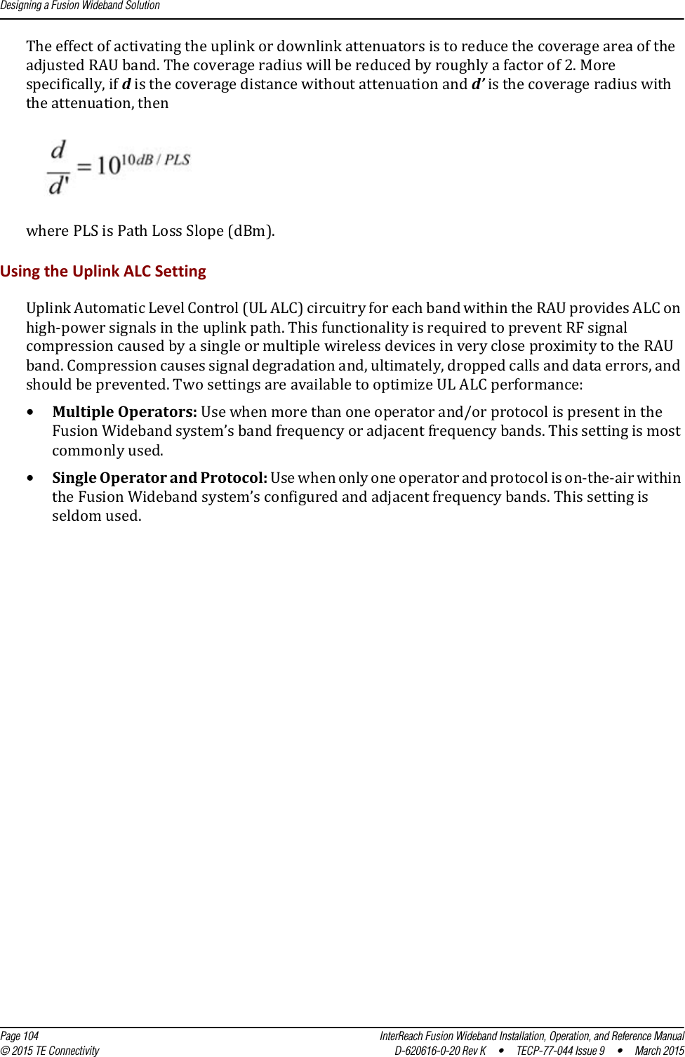
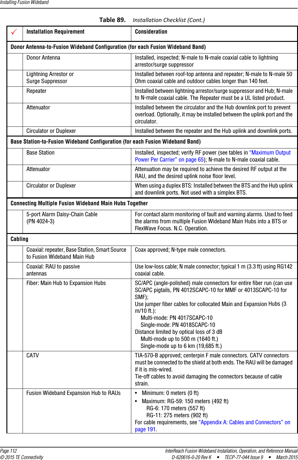
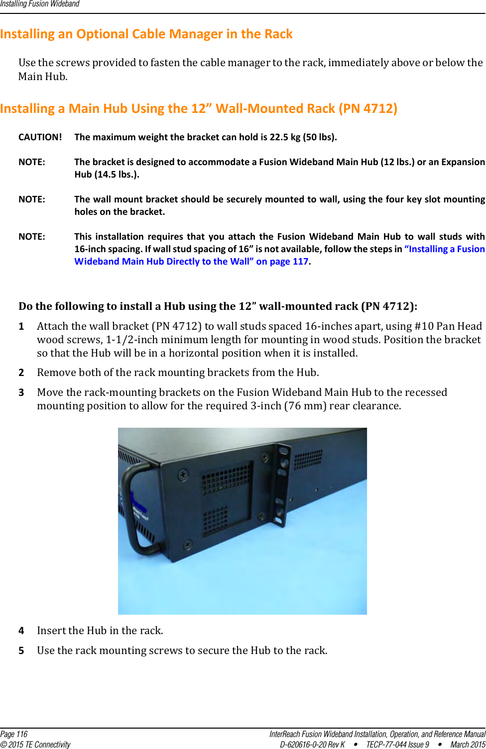
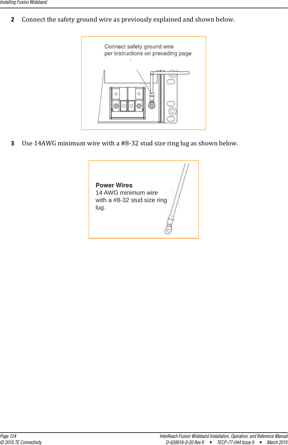
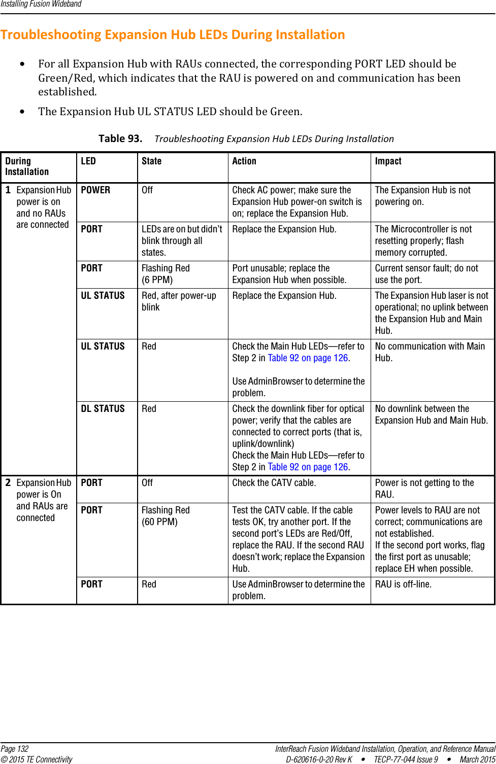
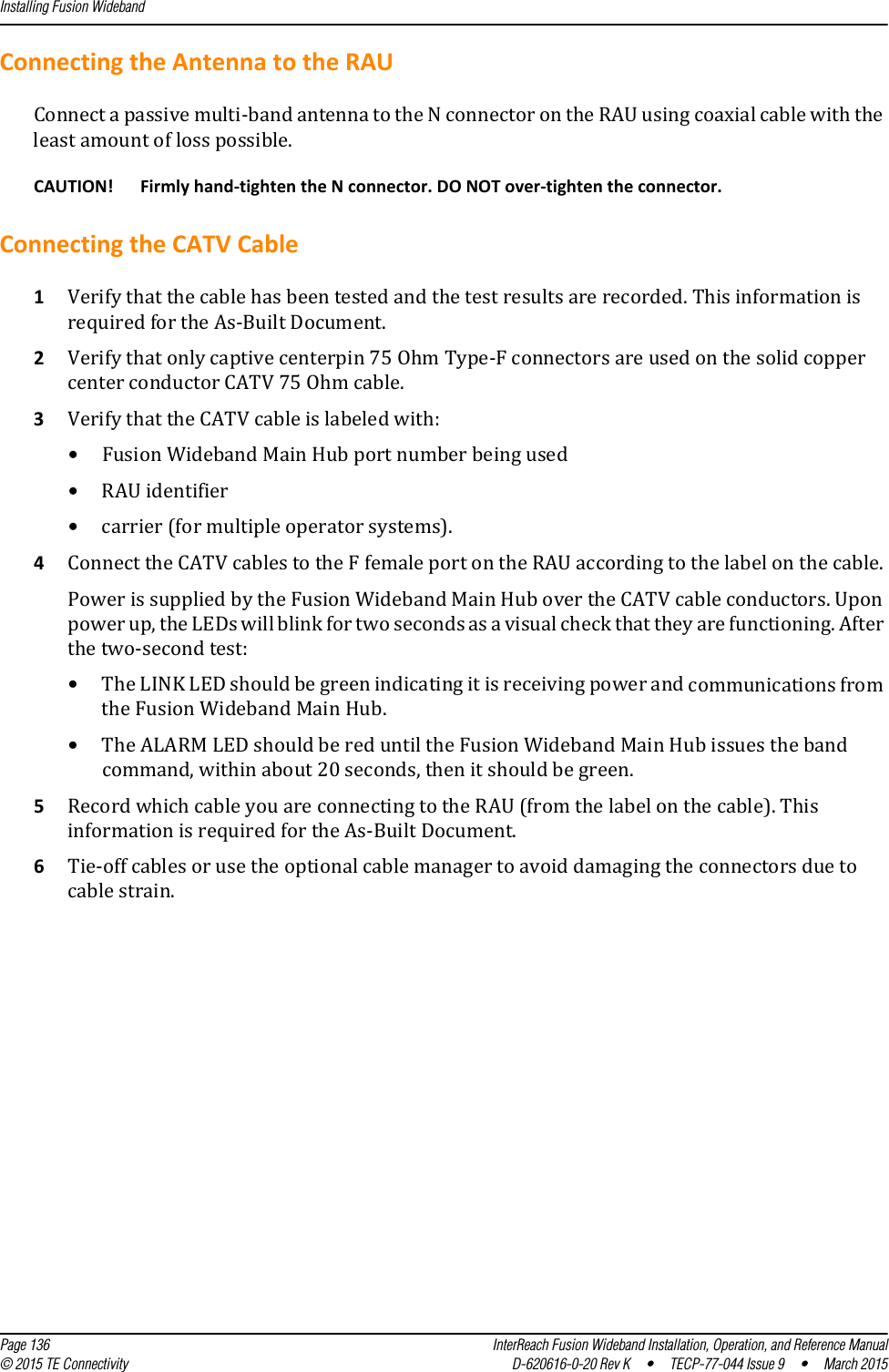
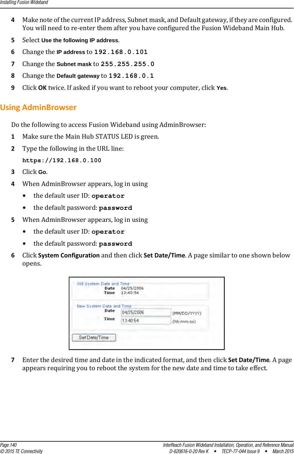
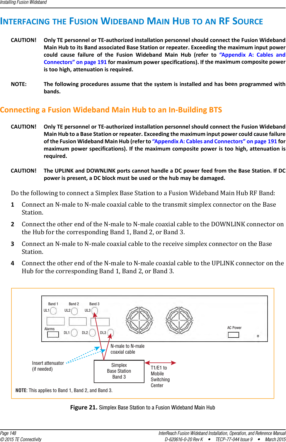
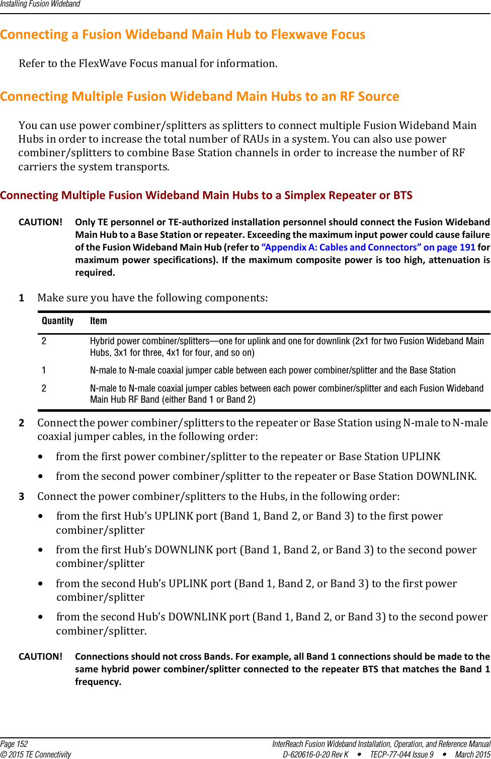
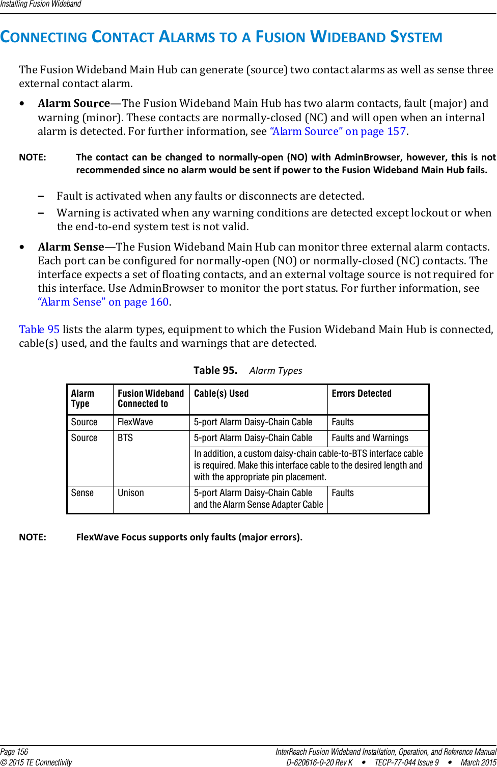
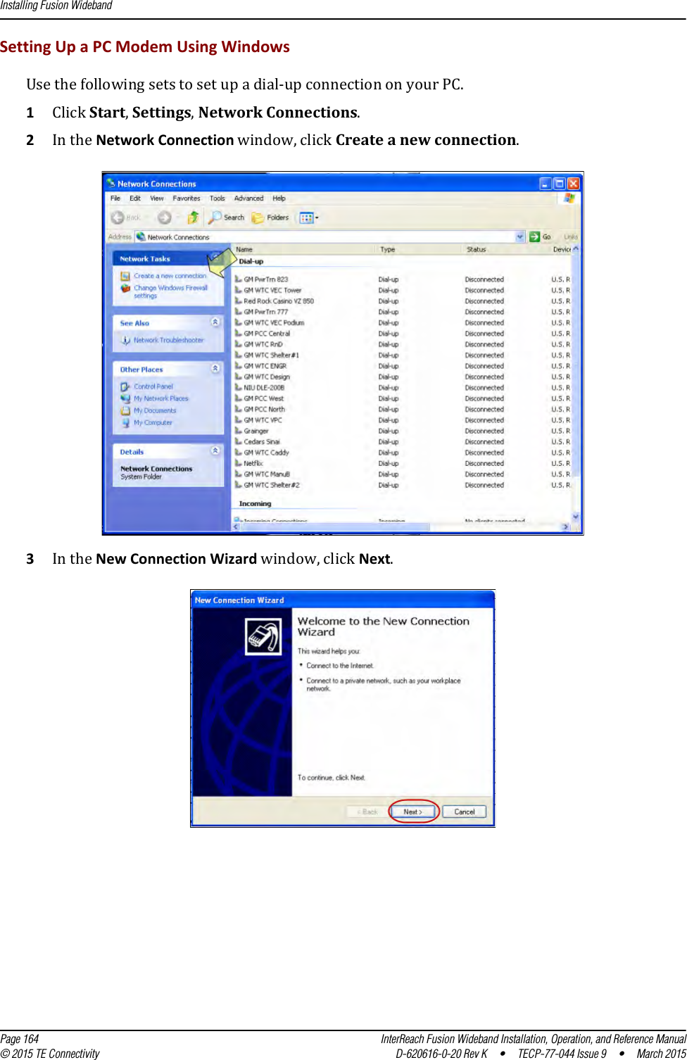
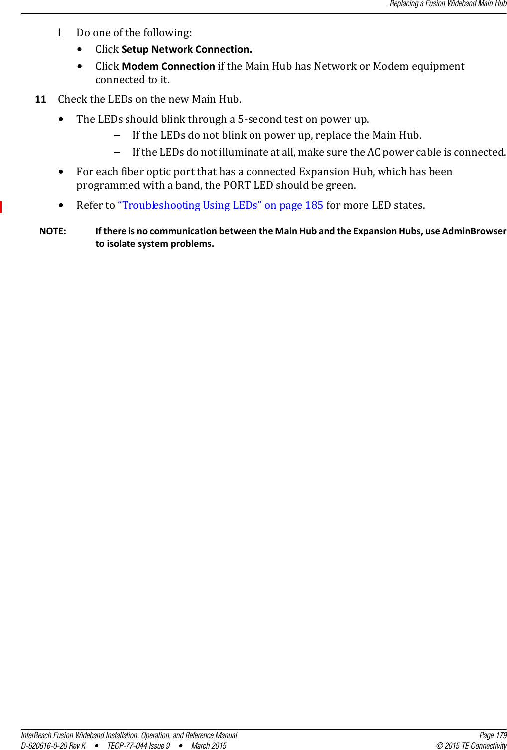
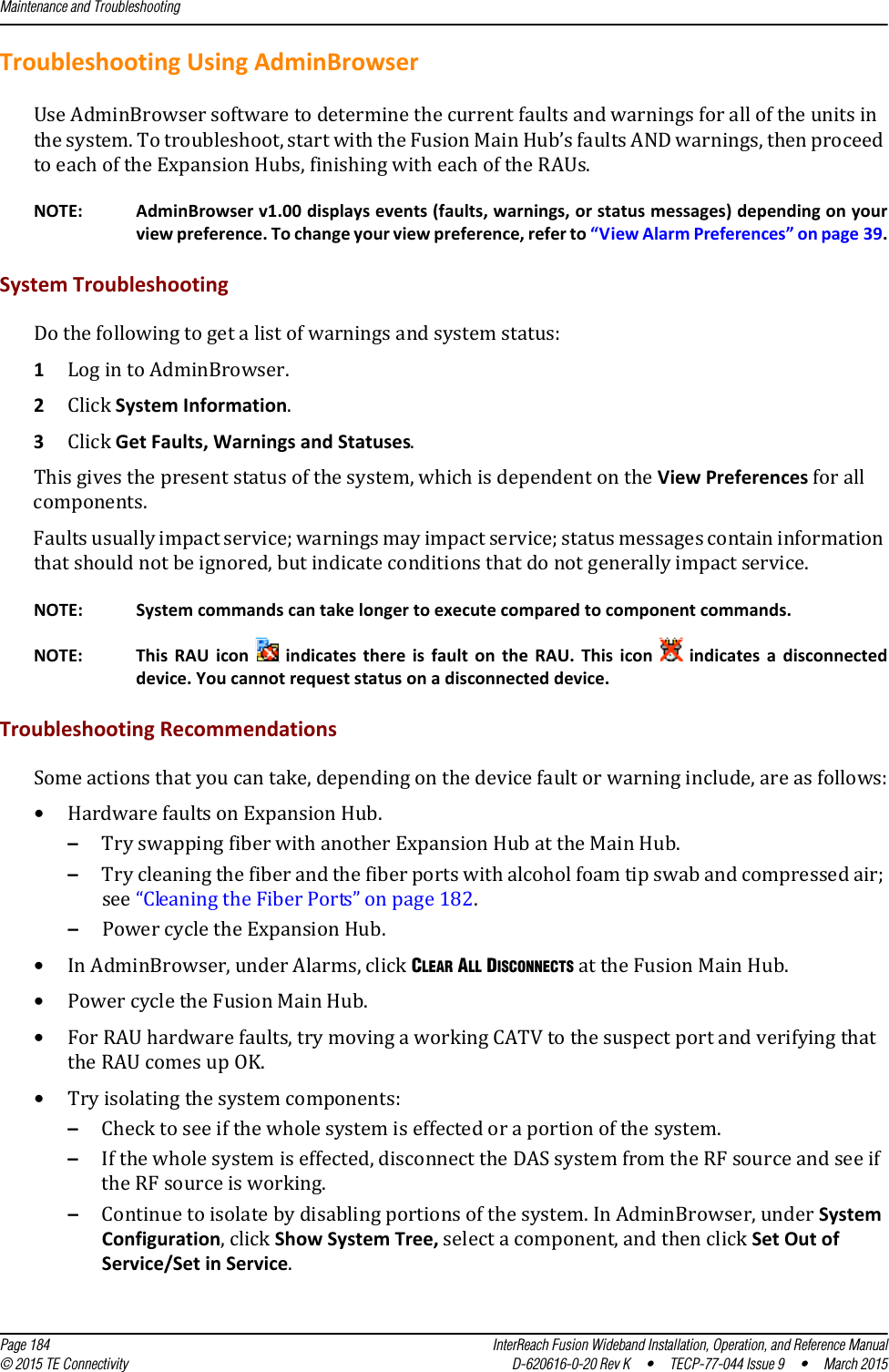
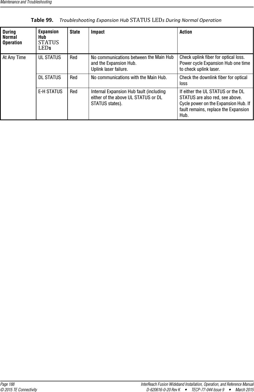
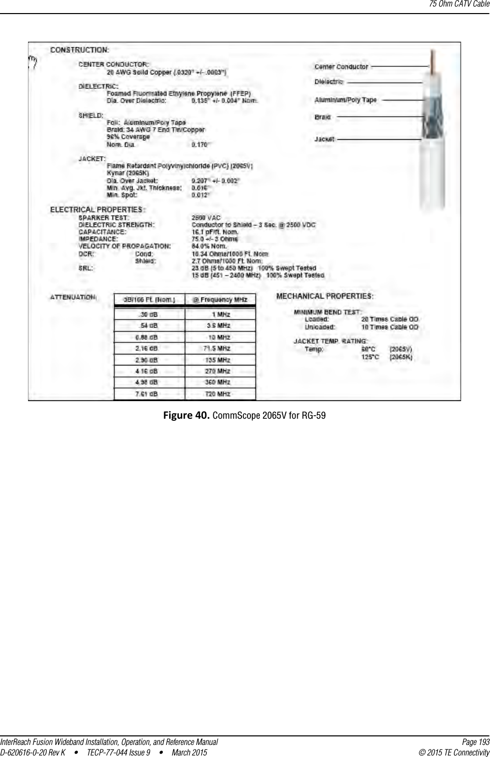
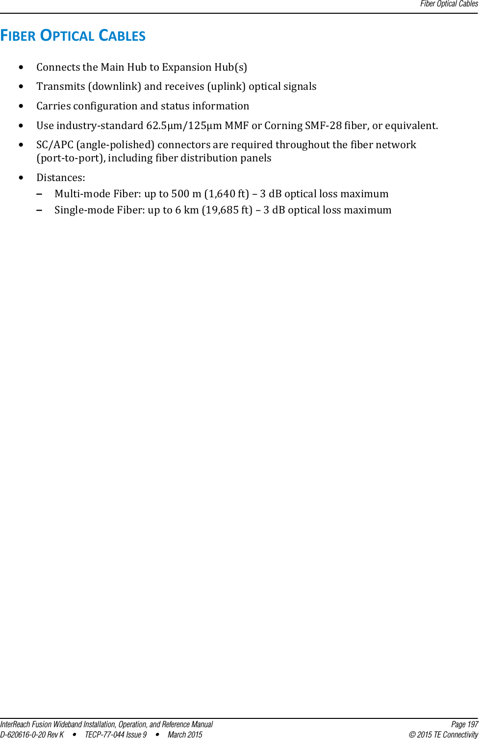
![Appendix C: Faults, Warnings, Status Tables for Fusion, Fusion Wideband, Fusion SingleStar Page 220 InterReach Fusion Wideband Installation, Operation, and Reference Manual© 2015 TE Connectivity D-620616-0-20 Rev K • TECP-77-044 Issue 9 • March 2015[M76]/S No UL test tone Port 4 (Band 3). Hub/Port UL path gain is low.[M77]/S Problem detected in the Hub. Contact TE Support for more information.[M78]/S Problem detected in the Hub. Contact TE Support for more information.[M79]/S Problem detected in the Hub. Contact TE Support for more information.[M80]/S Problem detected in the Hub. Contact TE Support for more information.[M81]/W Port 1 DL path loss is high. If the problem is on more than one port, replace the Hub. Switch the cable connection to a different hub port until the Hub can be replaced.[M82]/W Port 2 DL path loss is high. If the problem is on more than one port, replace the Hub. Switch the cable connection to a different hub port until the Hub can be replaced.[M83]/W Port 3 DL path loss is high. If the problem is on more than one port, replace the Hub. Switch the cable connection to a different hub port until the Hub can be replaced.[M84]/W Port 4 DL path loss is high. If the problem is on more than one port, replace the Hub. Switch the cable connection to a different hub port until the Hub can be replaced.[M85]/W Port 5 DL path loss is high. If the problem is on more than one port, replace the Hub. Switch the cable connection to a different hub port until the Hub can be replaced.[M86]/W Port 6 DL path loss is high. If the problem is on more than one port, replace the Hub. Switch the cable connection to a different hub port until the Hub can be replaced.[M87]/W Port 7 DL path loss is high. If the problem is on more than one port, replace the Hub. Switch the cable connection to a different hub port until the Hub can be replaced.[M88]/W Port 8 DL path loss is high. If the problem is on more than one port, replace the Hub. Switch the cable connection to a different hub port until the Hub can be replaced.[M89]/W Port 1 UL path loss is high. Check the cable for high RF loss. Switch the cable connection to a different hub port. If the problem on more than one port, replace the Hub, otherwise replace the RAU.[M90]/W Port 2 UL path loss is high. Check the cable for high RF loss. Switch the cable connection to a different hub port. If the problem is on more than one port, replace the Hub, otherwise replace the RAU.[M91]/W Port 3 UL path loss is high. Check the cable for high RF loss. Switch the cable connection to a different hub port. If the problem is on more than one port, replace the Hub, otherwise replace the RAU.[M92]/W Port 4 UL path loss is high. Check the cable for high RF loss. Switch the cable connection to a different hub port. If the problem is on more than one port, replace the Hub, otherwise replace the RAU.[M93]/W Port 5 UL path loss is high. Check the cable for high RF loss. Switch the cable connection to a different hub port. If the problem is on more than one port, replace the Hub, otherwise replace the RAU.Table 107. Warnings/Status Messages for Main Hubs (Cont.)Message Number/DefaultDescription Reason/Action](https://usermanual.wiki/ADC-Telecommunications/F0851-111/User-Guide-2572832-Page-228.png)
![Messages for Main HubsInterReach Fusion Wideband Installation, Operation, and Reference Manual Page 221D-620616-0-20 Rev K • TECP-77-044 Issue 9 • March 2015 © 2015 TE Connectivity[M94]/W Port 6 UL path loss is high. Check the cable for high RF loss. Switch the cable connection to a different hub port. If the problem is on more than one port, replace the Hub, otherwise replace the RAU.[M95]/W Port 7 UL path loss is high. Check the cable for high RF loss. Switch the cable connection to a different hub port. If the problem is on more than one port, replace the Hub, otherwise replace the RAU.[M96]/W Port 8 UL path loss is high. Check the cable for high RF loss. Switch the cable connection to a different hub port. If the problem is on more than one port, replace the Hub, otherwise replace the RAU.[M97]/W Port 1 UL path exceeds maximum gain. If the problem is common to more than one port, replace the Hub, otherwise check the RAU.[M98]/W Port 2 UL path exceeds maximum gain. If the problem is common to more than one port, replace the Hub, otherwise check the RAU.[M99]/W Port 2 UL path exceeds maximum gain. If the problem is common to more than one port, replace the Hub, otherwise check the RAU.[M100]/W Port 2 UL path exceeds maximum gain. If the problem is common to more than one port, replace the Hub, otherwise check the RAU.[M101]/W Port 2 UL path exceeds maximum gain. If the problem is common to more than one port, replace the Hub, otherwise check the RAU.[M102]/W Port 2 UL path exceeds maximum gain. If the problem is common to more than one port, replace the Hub, otherwise check the RAU.[M103]/W Port 2 UL path exceeds maximum gain. If the problem is common to more than one port, replace the Hub, otherwise check the RAU.[M104]/W Port 8 UL path exceeds maximum gain. If the problem is common to more than one port, replace the Hub, otherwise check the RAU.[M105]/W Port 1 54 VDC Power Enabled. Caution: Port 54 VDC power may be present at the output.[M106]/W Port 2 54 VDC Power Enabled. Caution: Port 54 VDC power may be present at the output.[M107]/W Port 3 54 VDC Power Enabled. Caution: Port 54 VDC power may be present at the output.[M108]/W Port 4 54 VDC Power Enabled. Caution: Port 54 VDC power may be present at the output.[M109]/W Port 5 54 VDC Power Enabled. Caution: Port 54 VDC power may be present at the output.[M110]/W Port 6 54 VDC Power Enabled. Caution: Port 54 VDC power may be present at the output.[M111]/W Port 7 54 VDC Power Enabled. Caution: Port 54 VDC power may be present at the output.[M112]/W Port 8 54 VDC Power Enabled. Caution: Port 54 VDC power may be present at the output.Table 107. Warnings/Status Messages for Main Hubs (Cont.)Message Number/DefaultDescription Reason/Action](https://usermanual.wiki/ADC-Telecommunications/F0851-111/User-Guide-2572832-Page-229.png)
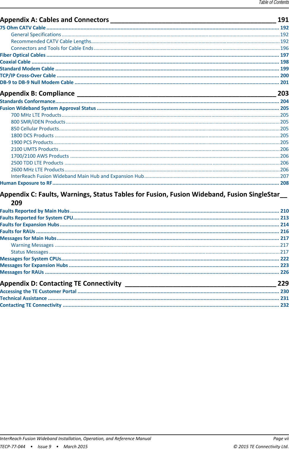
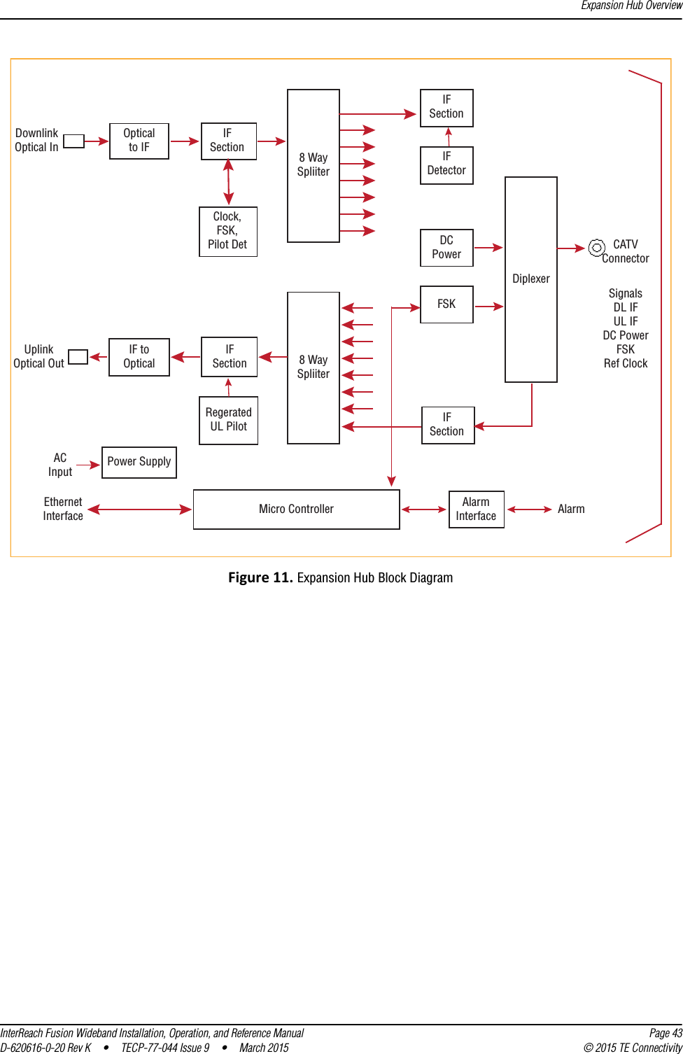
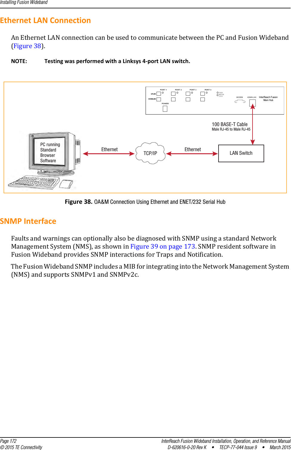
![Appendix C: Faults, Warnings, Status Tables for Fusion, Fusion Wideband, Fusion SingleStar Page 222 InterReach Fusion Wideband Installation, Operation, and Reference Manual© 2015 TE Connectivity D-620616-0-20 Rev K • TECP-77-044 Issue 9 • March 2015MESSAGES FOR SYSTEM CPUSIn Table 108, the message number is in the following form:[Snn]/X where •nn equals the message number•X equals the default of one of the following–S—Status–W—Warning.Table 108. Warning/Status Messages for System CPUs Message Number/ DefaultDescription Reason/Action[S01]/W Alarm Input 1. Check equipment connected to alarm input 1.[S02]/W Alarm Input 2. Check equipment connected to alarm input 2.[S03]/W Alarm Input 3. Check equipment connected to alarm input 3.[S04]/S Performed System Test System has just performed system test.[S05]/S Problem detected in the System CPU. Contact TE Support for more information.[S06]/S Loaded default etb file. Contact TE Support for more information.[S07]/S Loaded default SBC status file. Contact TE Support for more information.[S08]/S Problem detected in the System CPU. Contact TE Support for more information.[S09]/S TTL is full. Retrieve the TTL and erase.[S10]/S Problem detected in the System CPU. Contact TE Support for more information.[S11]/S Problem detected in the System CPU. Contact TE Support for more information.[S12]/S Loaded default Password file. Contact TE Support for more information.[S13]/S Loaded default sys config file. Contact TE Support for more information.[S14]/S Communication retries exceeded. Attempted command three times without response.[S15]/S Problem detected in the System CPU. Contact TE Support for more information.[S16]/S Problem detected in the System CPU. Contact TE Support for more information.](https://usermanual.wiki/ADC-Telecommunications/F0851-111/User-Guide-2572832-Page-230.png)
![Messages for Expansion HubsInterReach Fusion Wideband Installation, Operation, and Reference Manual Page 223D-620616-0-20 Rev K • TECP-77-044 Issue 9 • March 2015 © 2015 TE ConnectivityMESSAGES FOR EXPANSION HUBSTable 109. Warning/Status Message for Expansion Hubs Message Number/DefaultDescription Reason/Action[E01]/W Alarm Input 1. Check the equipment connected to alarm input 1.[E02]/W Alarm Input 2. Check the equipment connected to alarm input 2.[E03]/W Alarm Input 3. Check the equipment connected to alarm input 3.[E04]/S Problem detected in the EH. Contact TE Support for more information.[E05]/W SNMP Trap #1. TBD.[E06]/W SNMP Trap #2. TBD.[E07]/W SNMP Trap #3. TBD.[E08]/S Problem detected in the EH. Contact TE Support for more information.[E09]/S Fan 1 failure. Check the fan for proper rotation, air flow blockage, and dust accumulation. Replace the Hub on high temperature warning.[E10]/S Fan 2 failure. Check the fan for proper rotation, air flow blockage, and dust accumulation. Replace the Hub on high temperature warning.[E11]/W -5 VDC Monitor. DC power out of range, replace the Hub.[E12]/W 5 VDC Monitor. DC power out of range, replace the Hub.[E13]/W 9 VDC Monitor. DC power out of range, replace the Hub.[E14]/W 54 VDC Pwr Supply failure. DC port power supply out of range, replace the Hub.[E15]/W 3 VDC Monitor. DC power out of range, replace the Hub.[E16]/W 12 VDC Monitor. DC power out of range, replace the Hub.[E17]/W Temperature High. Reduce the ambient temperature, check for air flow blockage, fan rotation.[E18]/W DL path exceeds maximum gain. If the problem is common to more than one port, replace the MH, otherwise check the EH.[E19]/W DL path loss is high. Check the cable for high RF loss. Switch the cable connection to a different MH port. If the problem is on more than one port, replace the EH, otherwise replace the RAU.[E20]/W Hardware Failure (High UL Pilot). Cycle power once. If the fault persists, replace the EH.[E21]/W Hardware Failure (Low UL Pilot). Cycle power once. If the fault persists, replace the EH.[E22]/W Low optical input power. Check the downlink fiber connection.[E23]/W High laser current. Contact TE Support for more information.[E24]/S Problem detected in the EH. Contact TE Support for more information.[E25]/W Port 1 No DL test tone (Band 1). Hub/Port DL path gain is low.[E26]/W Port 2 No DL test tone (Band 1). Hub/Port DL path gain is low.[E27]/W Port 3 No DL test tone (Band 1). Hub/Port DL path gain is low.[E28]/W Port 4 No DL test tone (Band 1). Hub/Port DL path gain is low.[E29]/W Port 5 No DL test tone (Band 1). Hub/Port DL path gain is low.[E30]/W Port 6 No DL test tone (Band 1). Hub/Port DL path gain is low.[E31]/W Port 7 No DL test tone (Band 1). Hub/Port DL path gain is low.[E32]/W Port 8 No DL test tone (Band 1). Hub/Port DL path gain is low.[E33]/W Port 1 No DL test tone (Band 2). Hub/Port DL path gain is low.](https://usermanual.wiki/ADC-Telecommunications/F0851-111/User-Guide-2572832-Page-231.png)
![Appendix C: Faults, Warnings, Status Tables for Fusion, Fusion Wideband, Fusion SingleStar Page 224 InterReach Fusion Wideband Installation, Operation, and Reference Manual© 2015 TE Connectivity D-620616-0-20 Rev K • TECP-77-044 Issue 9 • March 2015[E34]/W Port 2 No DL test tone (Band 2). Hub/Port DL path gain is low.[E35]/W Port 3 No DL test tone (Band 2). Hub/Port DL path gain is low.[E36]/W Port 4 No DL test tone (Band 2). Hub/Port DL path gain is low.[E37]/W Port 5 No DL test tone (Band 2). Hub/Port DL path gain is low.[E38]/W Port 6 No DL test tone (Band 2). Hub/Port DL path gain is low.[E39]/W Port 7 No DL test tone (Band 2). Hub/Port DL path gain is low.[E40]/W Port 8 No DL test tone (Band 2). Hub/Port DL path gain is low.[E41]/W Port 1 No DL test tone (Band 3). Hub/Port DL path gain is low.[E42]/W Port 2 No DL test tone (Band 3). Hub/Port DL path gain is low.[E43]/W Port 3 No DL test tone (Band 3). Hub/Port DL path gain is low.[E44]/W Port 4 No DL test tone (Band 3). Hub/Port DL path gain is low.[E45]/W Port 5 No DL test tone (Band 3). Hub/Port DL path gain is low.[E46]/W Port 6 No DL test tone (Band 3). Hub/Port DL path gain is low.[E47]/W Port 7 No DL test tone (Band 3). Hub/Port DL path gain is low.[E48]/W Port 8 No DL test tone (Band 3). Hub/Port DL path gain is low.[E49]/W Port 1 DL path loss is high. If the problem is on more than one port, replace the Hub. Switch the cable connection to a different hub port until the Hub can be replaced.[E50]/W Port 2 DL path loss is high. If the problem is on more than one port, replace the Hub. Switch the cable connection to a different hub port until the Hub can be replaced.[E51]/W Port 3 DL path loss is high. If the problem is on more than one port, replace the Hub. Switch the cable connection to a different hub port until the Hub can be replaced.[E52]/W Port 4 DL path loss is high. If the problem is on more than one port, replace the Hub. Switch the cable connection to a different hub port until the Hub can be replaced.[E53]/W Port 5 DL path loss is high. If the problem is on more than one port, replace the Hub. Switch the cable connection to a different hub port until the Hub can be replaced.[E54]/W Port 6 DL path loss is high. If the problem is on more than one port, replace the Hub. Switch the cable connection to a different hub port until the Hub can be replaced.[E55]/W Port 7 DL path loss is high. If the problem is on more than one port, replace the Hub. Switch the cable connection to a different hub port until the Hub can be replaced.[E56]/W Port 8 DL path loss is high. If the problem is on more than one port, replace the Hub. Switch the cable connection to a different hub port until the Hub can be replaced.[E57]/W Port 1 UL path loss is high. Check the cable for high RF loss. Switch the cable connection to a different hub port. If the problem is on more than one port, replace the Hub, otherwise replace the RAU.[E58]/W Port 2 UL path loss is high. Check the cable for high RF loss. Switch the cable connection to a different hub port. If the problem is on more than one port, replace the Hub, otherwise replace the RAU.[E59]/W Port 3 UL path loss is high. Check the cable for high RF loss. Switch the cable connection to a different hub port. If the problem is on more than one port, replace the Hub, otherwise replace the RAU.[E60]/W Port 4 UL path loss is high. Check the cable for high RF loss. Switch the cable connection to a different hub port. If the problem is on more than one port, replace the Hub, otherwise replace the RAU.Table 109. Warning/Status Message for Expansion Hubs (Cont.)Message Number/DefaultDescription Reason/Action](https://usermanual.wiki/ADC-Telecommunications/F0851-111/User-Guide-2572832-Page-232.png)
![Messages for Expansion HubsInterReach Fusion Wideband Installation, Operation, and Reference Manual Page 225D-620616-0-20 Rev K • TECP-77-044 Issue 9 • March 2015 © 2015 TE Connectivity[E61]/W Port 5 UL path loss is high. Check the cable for high RF loss. Switch the cable connection to a different hub port. If the problem is on more than one port, replace the Hub, otherwise replace the RAU.[E62]/W Port 6 UL path loss is high. Check the cable for high RF loss. Switch the cable connection to a different hub port. If the problem is on more than one port, replace the Hub, otherwise replace the RAU.[E63]/W Port 7 UL path loss is high. Check the cable for high RF loss. Switch the cable connection to a different hub port. If the problem is on more than one port, replace the Hub, otherwise replace the RAU.[E64]/W Port 8 UL path loss is high. Check the cable for high RF loss. Switch the cable connection to a different hub port. If the problem is on more than one port, replace the Hub, otherwise replace the RAU.[E65]/W Port 1 UL path exceeds maximum gain. If the problem is common to more than one port, replace the Hub, otherwise check RAU.[E66]/W Port 2 UL path exceeds maximum gain. If the problem is common to more than one port, replace the Hub, otherwise check RAU.[E67]/W Port 3 UL path exceeds maximum gain. If the problem is common to more than one port, replace the Hub, otherwise check RAU.[E68]/W Port 4 UL path exceeds maximum gain. If the problem is common to more than one port, replace the Hub, otherwise check RAU.[E69]/W Port 5 UL path exceeds maximum gain. If the problem is common to more than one port, replace the Hub, otherwise check RAU.[E70]/W Port 6 UL path exceeds maximum gain. If the problem is common to more than one port, replace the Hub, otherwise check RAU.[E71]/W Port 7 UL path exceeds maximum gain. If problem is common to more than one port, replace the Hub, otherwise check RAU.[E72]/W Port 8 UL path exceeds maximum gain. If the problem is common to more than one port, replace the Hub, otherwise check RAU.[E73]/W Port 1 54 VDC Power Enabled. Caution: Port 54 VDC power may be present at the output.[E74]/W Port 2 54 VDC Power Enabled. Caution: Port 54 VDC power may be present at the output.[E75]/W Port 3 54 VDC Power Enabled. Caution: Port 54 VDC power may be present at the output.[E76]/W Port 4 54 VDC Power Enabled. Caution: Port 54 VDC power may be present at the output.[E77]/W Port 5 54 VDC Power Enabled. Caution: Port 54 VDC power may be present at the output.[E78]/W Port 6 54 VDC Power Enabled. Caution: Port 54 VDC power may be present at the output.[E79]/W Port 7 54 VDC Power Enabled. Caution: Port 54 VDC power may be present at the output.[E80]/W Port 8 54 VDC Power Enabled. Caution: Port 54 VDC power may be present at the output.Table 109. Warning/Status Message for Expansion Hubs (Cont.)Message Number/DefaultDescription Reason/Action](https://usermanual.wiki/ADC-Telecommunications/F0851-111/User-Guide-2572832-Page-233.png)
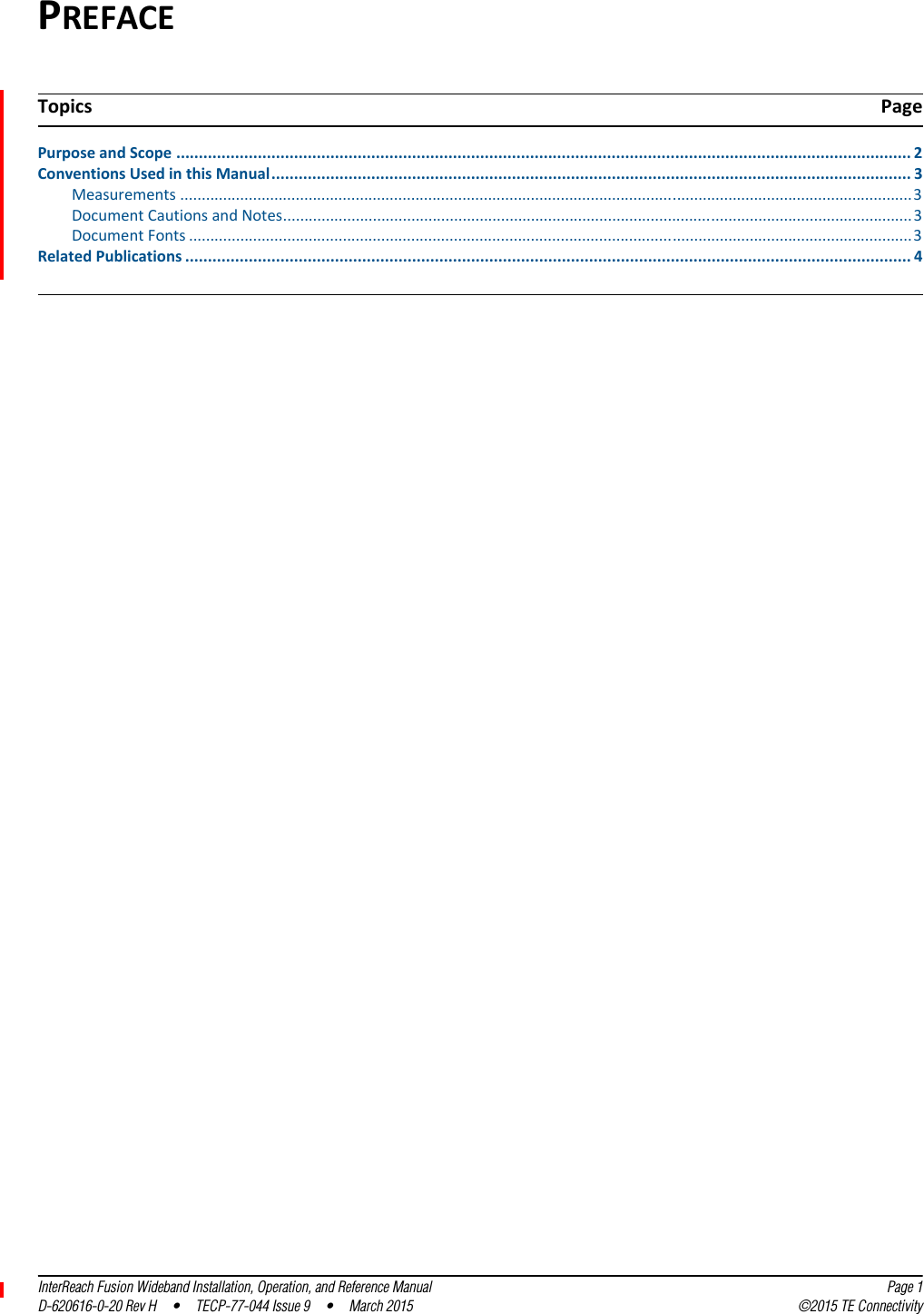
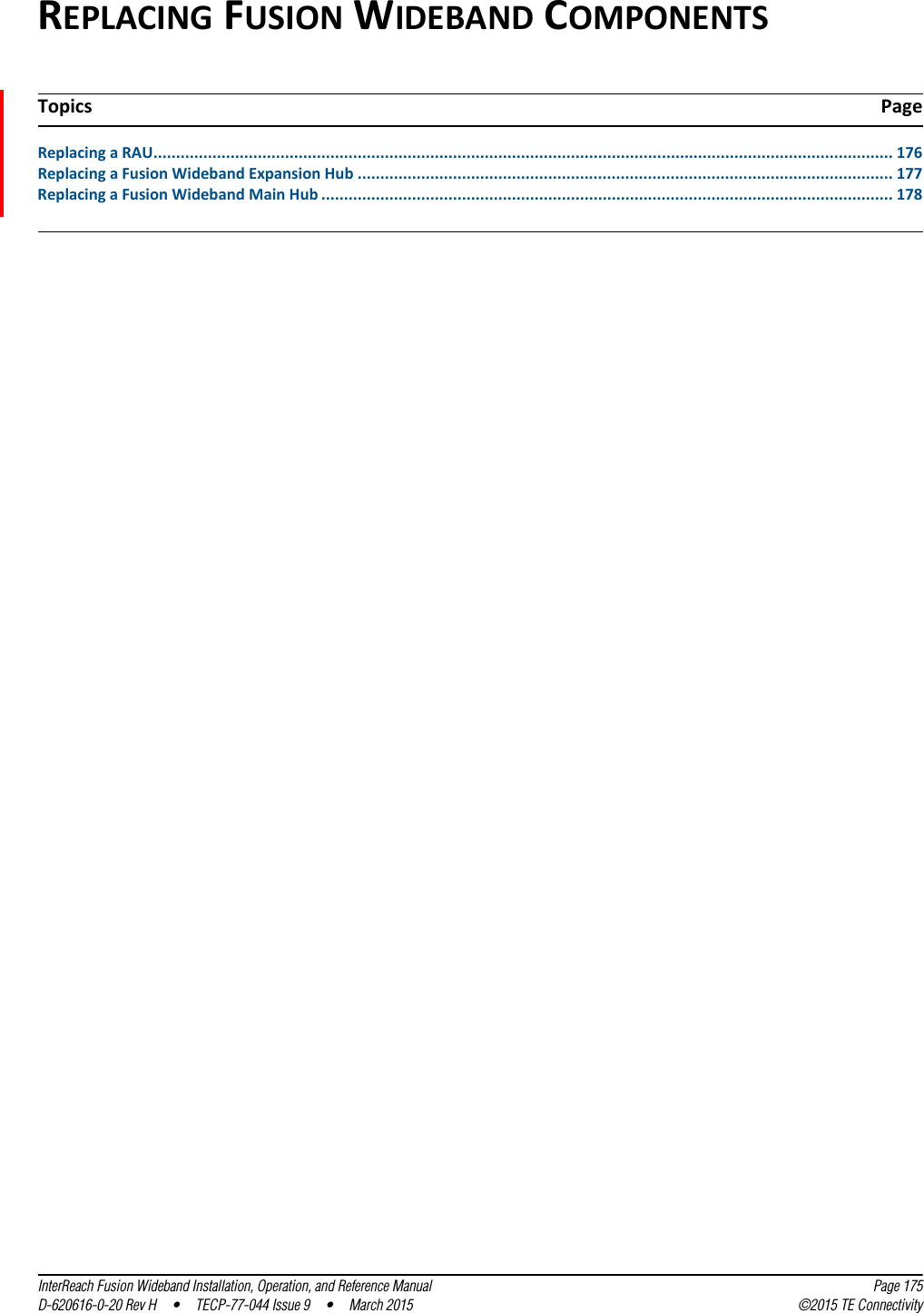
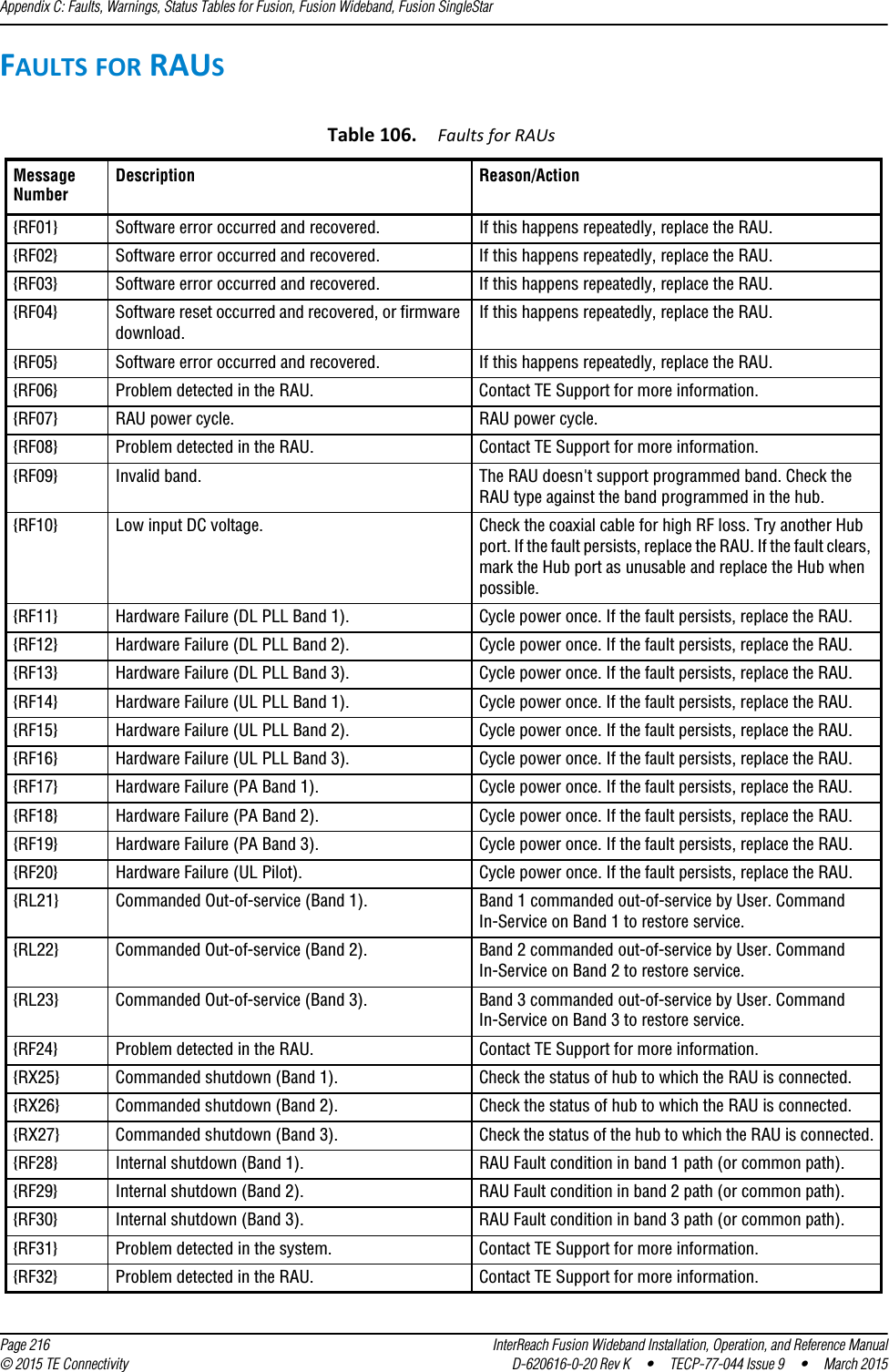
![Appendix C: Faults, Warnings, Status Tables for Fusion, Fusion Wideband, Fusion SingleStar Page 226 InterReach Fusion Wideband Installation, Operation, and Reference Manual© 2015 TE Connectivity D-620616-0-20 Rev K • TECP-77-044 Issue 9 • March 2015MESSAGES FOR RAUSIn Table 110, the message number is in the following form:[Rnn]/X where •nn equals the message number•X equals the default of one of the following–S—Status–W—Warning.Table 110. Warning/Status Messages for RAUs Message Number DefaultDescription Reason/Action[R01]/W Temperature High. Check RAU location for excessive temperature; check for air flow blockage and/or incorrect installation. Move the RAU to a cooler environment.[R02]/W No communications from Hub. Check the cable for high RF loss. Switch the cable connection to a different hub port. If the problem persists, replace the RAU.[R03]/W DL RF path loss is too high. Check the cable for high RF loss. Switch the cable connection to a different hub port. If the problem persists, replace the RAU.[R04]/W DL RF path exceeds maximum gain. Check the Hub for proper operation; switch the cable connection to a different hub port. If the problem persists, replace the RAU.[R05]/S DL RF path problem (Band 1). Unable to complete the DL system end-to-end test, replace the RAU when possible.[R06]/S DL RF path problem (Band 2). Unable to complete the DL system end-to-end test, replace the RAU when possible.[R07]/S DL RF path problem (Band 3). Unable to complete the DL system end-to-end test, replace the RAU when possible.[R08]/S System test required. Run system test.[R09]/W Antenna Disconnected. Check RAU antenna connection; re-run system test.[R10]/S UL RF path problem (Band 1). Unable to complete the UL system end-to-end test, replace the RAU when possible.[R11]/S UL RF path problem (Band 2). Unable to complete the UL system end-to-end test, replace the RAU when possible.[R12]/S UL RF path problem (Band 3). Unable to complete the UL system end-to-end test, replace the RAU when possible.[R13]/S Problem detected in the RAU. Contact TE Support for more information.[R14]/S Problem detected in the RAU. Contact TE Support for more information.[R15]/S Problem detected in the RAU. Contact TE Support for more information.[R16]/S Problem detected in the RAU. Contact TE Support for more information.[R17]/S Antenna disconnected (Band 1). Check the RAU Band 1 antenna, then rerun the system test.[R18]/S Antenna disconnected (Band 2). Check the RAU Band 2 antenna, then rerun the system test.[R19]/S Hardware Failure (UL FD PLL Band 1). Unable to complete a UL system end-to-end test. Replace the RAU when possible.[R20]/W TDD signaling tone outside valid range (Band 1). If the Main Hub and Expansion Hub are okay, replace the RAU.](https://usermanual.wiki/ADC-Telecommunications/F0851-111/User-Guide-2572832-Page-234.png)
![Messages for RAUsInterReach Fusion Wideband Installation, Operation, and Reference Manual Page 227D-620616-0-20 Rev K • TECP-77-044 Issue 9 • March 2015 © 2015 TE Connectivity[R21]/W TDD signaling tone outside valid range (Band 2). If the Main Hub and Expansion Hub are okay, replace the RAU.[R22]/S High PA current (Band 1). The unit is operating with reduced gain. Verify that the input signal is at the appropriate level. If the problem persists, replace the RAU when possible.[R23]/S High PA current (Band 2). The unit is operating with reduced gain. Verify that the input signal is at the appropriate level. If the problem persists, replace the RAU when possible.Table 110. Warning/Status Messages for RAUs (Cont.)Message Number DefaultDescription Reason/Action](https://usermanual.wiki/ADC-Telecommunications/F0851-111/User-Guide-2572832-Page-235.png)