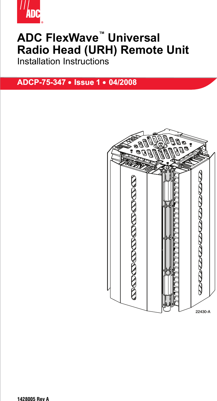
ADC Telecommunications FWURH08B FlexWave™ URH - Cellular User Manual

ADC Telecommunications Inc FlexWave™ URH - Cellular

User manual

ADC FlexWave™ UniversalRadio Head (URH) Remote UnitInstallation InstructionsADCP-75-347 • Issue 1 • 04/2008ADCP-75-347 • Issue 1 • 04/20081428005 Rev A22430-A
ADCP-75-347 • Issue 1 • 04/2008 • PrefacePage iiCOPYRIGHT© 2008, ADC Telecommunications, Inc. All Rights ReservedREVISION HISTORYTRADEMARK INFORMATIONADC is a registered trademark of ADC Telecommunications, Inc., FlexWave is a trademark of ADC Telecommunications, Inc.DISCLAIMER OF LIABILITYContents herein are current as of the date of publication. ADC reserves the right to change the contents without prior notice. In no event shall ADC be liable for any damages resulting from loss of data, loss of use, or loss of profits and ADC further disclaims any and all liability for indirect, incidental, special, consequential or other similar damages. This disclaimer of liability applies to all products, publications and services during and after the warranty period.This publication may be verified at any time by contacting ADC’s Technical Assistance Center at 1-800-366-3891, extension 73475 (in U.S.A. or Canada) or 952-917-3475 (outside U.S.A. and Canada), or by e-mail to connectivity_tac@adc.com.ISSUE DATE REASON FOR CHANGE1 04/2008 OriginalADC Telecommunications, Inc.P.O. Box 1101, Minneapolis, Minnesota 55440-1101In U.S.A. and Canada: 1-800-366-3891Outside U.S.A. and Canada: (952) 938-8080Fax: (952) 917-1717
ADCP-75-347 • Issue 1 • 04/2008 • PrefacePage iii© 2008, ADC Telecommunications, Inc.TABLE OF CONTENTSContent PageAbout This Manual   . . . . . . . . . . . . . . . . . . . . . . . . . . . . . . . . . . . . . . . . . . . . . . . . . . . . . . . . . . . . . . . . . . . . . . . . . . .  vRelated Publications . . . . . . . . . . . . . . . . . . . . . . . . . . . . . . . . . . . . . . . . . . . . . . . . . . . . . . . . . . . . . . . . . . . . . . . . . .  vAdmonishments  . . . . . . . . . . . . . . . . . . . . . . . . . . . . . . . . . . . . . . . . . . . . . . . . . . . . . . . . . . . . . . . . . . . . . . . . . . . . .  vGeneral Safety Precautions   . . . . . . . . . . . . . . . . . . . . . . . . . . . . . . . . . . . . . . . . . . . . . . . . . . . . . . . . . . . . . . . . . . . . .  vSTANDARDS CERTIFICATION   . . . . . . . . . . . . . . . . . . . . . . . . . . . . . . . . . . . . . . . . . . . . . . . . . . . . . . . . . . . . . . . . . . . . viList of Acronyms and Abbreviations . . . . . . . . . . . . . . . . . . . . . . . . . . . . . . . . . . . . . . . . . . . . . . . . . . . . . . . . . . . . . . .  vii1 DESCRIPTION . . . . . . . . . . . . . . . . . . . . . . . . . . . . . . . . . . . . . . . . . . . . . . . . . . . . . . . . . . . . . . . . . . . . . . . . . . 11.1 RF Spectrums . . . . . . . . . . . . . . . . . . . . . . . . . . . . . . . . . . . . . . . . . . . . . . . . . . . . . . . . . . . . . . . . . . . . 11.2 Primary Components . . . . . . . . . . . . . . . . . . . . . . . . . . . . . . . . . . . . . . . . . . . . . . . . . . . . . . . . . . . . . . . 31.3 Mounting . . . . . . . . . . . . . . . . . . . . . . . . . . . . . . . . . . . . . . . . . . . . . . . . . . . . . . . . . . . . . . . . . . . . . . . 31.4 Fault Detection and Alarm Reporting  . . . . . . . . . . . . . . . . . . . . . . . . . . . . . . . . . . . . . . . . . . . . . . . . . . . . 31.5 FlexWave URH RU Dimensions . . . . . . . . . . . . . . . . . . . . . . . . . . . . . . . . . . . . . . . . . . . . . . . . . . . . . . . . 41.6 Wavelength Division Multiplexer System  . . . . . . . . . . . . . . . . . . . . . . . . . . . . . . . . . . . . . . . . . . . . . . . . . 51.7 Antenna Cable Connections. . . . . . . . . . . . . . . . . . . . . . . . . . . . . . . . . . . . . . . . . . . . . . . . . . . . . . . . . . . 51.8 Powering . . . . . . . . . . . . . . . . . . . . . . . . . . . . . . . . . . . . . . . . . . . . . . . . . . . . . . . . . . . . . . . . . . . . . . . 51.9 Grounding  . . . . . . . . . . . . . . . . . . . . . . . . . . . . . . . . . . . . . . . . . . . . . . . . . . . . . . . . . . . . . . . . . . . . . . 51.10 Cooling  . . . . . . . . . . . . . . . . . . . . . . . . . . . . . . . . . . . . . . . . . . . . . . . . . . . . . . . . . . . . . . . . . . . . . . . . 51.11 Lightning Surge Suppressor (Accessory). . . . . . . . . . . . . . . . . . . . . . . . . . . . . . . . . . . . . . . . . . . . . . . . . . 61.12 User Interface . . . . . . . . . . . . . . . . . . . . . . . . . . . . . . . . . . . . . . . . . . . . . . . . . . . . . . . . . . . . . . . . . . . . 62 UNPACKING AND INSPECTION  . . . . . . . . . . . . . . . . . . . . . . . . . . . . . . . . . . . . . . . . . . . . . . . . . . . . . . . . . . . . . . 73 MOUNTING PROCEDURES  . . . . . . . . . . . . . . . . . . . . . . . . . . . . . . . . . . . . . . . . . . . . . . . . . . . . . . . . . . . . . . . . . 84 INSTALLATION PROCEDURES . . . . . . . . . . . . . . . . . . . . . . . . . . . . . . . . . . . . . . . . . . . . . . . . . . . . . . . . . . . . . . . 84.1 Installation Overview . . . . . . . . . . . . . . . . . . . . . . . . . . . . . . . . . . . . . . . . . . . . . . . . . . . . . . . . . . . . . . . 94.1.1 Installation Hardware Provided with RU . . . . . . . . . . . . . . . . . . . . . . . . . . . . . . . . . . . . . . . . . . . 94.1.2 Tools and Materials Required . . . . . . . . . . . . . . . . . . . . . . . . . . . . . . . . . . . . . . . . . . . . . . . . . . 94.2 Network Cable Installation  . . . . . . . . . . . . . . . . . . . . . . . . . . . . . . . . . . . . . . . . . . . . . . . . . . . . . . . . . .  104.3 Quad Fiber Cable Installation  . . . . . . . . . . . . . . . . . . . . . . . . . . . . . . . . . . . . . . . . . . . . . . . . . . . . . . . .  114.4 Antenna Cable Installation  . . . . . . . . . . . . . . . . . . . . . . . . . . . . . . . . . . . . . . . . . . . . . . . . . . . . . . . . . .  124.5 Ground Wire Installation. . . . . . . . . . . . . . . . . . . . . . . . . . . . . . . . . . . . . . . . . . . . . . . . . . . . . . . . . . . .  134.6 AC Power Wiring Installation. . . . . . . . . . . . . . . . . . . . . . . . . . . . . . . . . . . . . . . . . . . . . . . . . . . . . . . . .  144.7 Solar Shield Installation . . . . . . . . . . . . . . . . . . . . . . . . . . . . . . . . . . . . . . . . . . . . . . . . . . . . . . . . . . . .  174.8 Touch-Up Painting . . . . . . . . . . . . . . . . . . . . . . . . . . . . . . . . . . . . . . . . . . . . . . . . . . . . . . . . . . . . . . . .  184.9 Power-Up and Testing  . . . . . . . . . . . . . . . . . . . . . . . . . . . . . . . . . . . . . . . . . . . . . . . . . . . . . . . . . . . . .  194.10 URH Remote Unit Replacement. . . . . . . . . . . . . . . . . . . . . . . . . . . . . . . . . . . . . . . . . . . . . . . . . . . . . . .  195 INSTALLING REMOTE UNIT ON THE MOUNTING BRACKET. . . . . . . . . . . . . . . . . . . . . . . . . . . . . . . . . . . . . . . . . . .  196 SPECIFICATIONS. . . . . . . . . . . . . . . . . . . . . . . . . . . . . . . . . . . . . . . . . . . . . . . . . . . . . . . . . . . . . . . . . . . . . . .  217 POWER CONSUMPTION . . . . . . . . . . . . . . . . . . . . . . . . . . . . . . . . . . . . . . . . . . . . . . . . . . . . . . . . . . . . . . . . . .  227.1 Power Calculation . . . . . . . . . . . . . . . . . . . . . . . . . . . . . . . . . . . . . . . . . . . . . . . . . . . . . . . . . . . . . . . .  228 CUSTOMER INFORMATION AND ASSISTANCE . . . . . . . . . . . . . . . . . . . . . . . . . . . . . . . . . . . . . . . . . . . . . . . . . . .  24
ADCP-75-347 • Issue 1 • 04/2008 • PrefacePage iv© 2008, ADC Telecommunications, Inc.TABLE OF CONTENTSContent PageBlank
ADCP-75-347 • Issue 1 • 04/2008 • PrefacePage v© 2008, ADC Telecommunications, Inc.ABOUT THIS MANUALThis manual describes how to install and cable a URH Remote Unit in an outdoor environment such as pole or mast. RELATED PUBLICATIONSListed below are related manuals, their content, and their publication numbers. Copies of these publications can be ordered by contacting the Technical Assistance Center at 1-800-366-3891, extension 73476 (in U.S.A. or Canada) or 952-917-3476 (outside U.S.A. and Canada). All ADC technical publications are available for downloading from the ADC web site at www.adc.com. ADC FlexWave™ Universal Radio Head (URH) Host Unit Installation Instructions78-348ADC FlexWave™ Universal Radio Head (URH) System User Manual 75-349ADC FlexWave™ Universal Radio Head (URH) System EMS User Manual 75-350ADC FlexWave™ URH Remote Unit Mounting Kit Installation Instructions 75-351ADMONISHMENTSImportant safety admonishments are used throughout this manual to warn of possible hazards to persons or equipment. An admonishment identifies a possible hazard and then explains what may happen if the hazard is not avoided. The admonishments — in the form of Dangers, Warnings, and Cautions — must be followed at all times. These warnings are flagged by use of the triangular alert icon (seen below), and are listed in descending order of severity of injury or damage and likelihood of occurrence.GENERAL SAFETY PRECAUTIONS-Title/Description ADCP NumberDanger: Danger is used to indicate the presence of a hazard that will cause severe personal injury, death, or substantial property damage if the hazard is not avoided.Warning: Warning is used to indicate the presence of a hazard that can cause severe personal injury, death, or substantial property damage if the hazard is not avoided.Caution:  Caution is used to indicate the presence of a hazard that will or can cause minor personal injury or property damage if the hazard is not avoided.Warning:  Wet conditions increase the potential for receiving an electrical shock when installing or using electrically-powered equipment. To prevent electrical shock, never install or use electrical equipment in a wet location or during a lightning storm.
ADCP-75-347 • Issue 1 • 04/2008 • PrefacePage vi© 2008, ADC Telecommunications, Inc.STANDARDS CERTIFICATIONFCC: This equipment complies with the applicable sections of Title 47 CFR Part 15 (Host unit), Part 22 (800 MHz Cellular), Part 24 (1900 MHz - PCS), and Part 90 (800/900 - SMR).IC: This equipment complies with the applicable sections of RSS-131. The term “IC:” before the radio certification number only signifies that Industry Canada Technical Specifications were met.The Manufacturer's rated output power of this equipment is for single carrier operation. For situations when multiple carrier signals are present, the rating would have to be reduced by 3.5 dB, especially where the output signal is re-radiated and can cause interference to adjacent band users. This power reduction is to be by means of input power or gain reduction and not by an attenuator at the output of the device.Note: To comply with Maximum Permissible Exposure (MPE) requirements, the maximum composite output form the antenna cannot exceed 1000 Watts ERP (Cellular and SMR), the antenna cannot exceed 1640 Watts EIRP (PCS), and the antenna must be permanently installed in a fixed location that provides at least 6 meters (20 feet) of separation from all persons.UL/CUL: This will be installed in a restricted access location. This equipment complies with NEMA Type 6, per UL and CUL 50, Standard for Enclosures for Electrical Equipment. This equipment provides the degree of protection specified by IP67 as defined in IEC Publication 529.FDA/CDRH: This equipment uses a Class 1 LASER according to FDA/CDRH Rules. This product conforms to all applicable standards of 21 CFR Part 1040.Caution: Modifications not expressly approved by the party responsible for compliance could void the user's authority to operate the equipment.Danger: This equipment uses a Class 1 Laser according to FDA/CDRH rules. Laser radiation can seriously damage the retina of the eye. Do not look into the ends of any optical fiber. Do not look directly into the optical transceiver of any digital unit or exposure to laser radiation may result. An optical power meter should be used to verify active fibers. A protective cap or hood MUST be immediately placed over any radiating transceiver or optical fiber connector to avoid the potential of dangerous amounts of radiation exposure. This practice also prevents dirt particles from entering the adapter or connector.Caution: This system is a RF Transmitter and continuously emits RF energy. Maintain 3 foot (91.4 cm) minimum clearance from the antenna while the system is operating. Wherever possible, shut down the RAN before servicing the antenna.Caution:  Always allow sufficient fiber length to permit routing of patch cords and pigtails without severe bends. Fiber optic patch cords or pigtails may be permanently damaged if bent or curved to a radius of less than 2 inches (5.1 cm). Caution: Exterior surfaces of the RU may be hot. Use caution during servicing. Caution: Cooling fins on the Remote Unit may have sharp corners and edges, to prevent cuts and scrapes always wear gloves and appropriate protective clothing when handling the Remote Unit.
ADCP-75-347 • Issue 1 • 04/2008 • PrefacePage vii© 2008, ADC Telecommunications, Inc.LIST OF ACRONYMS AND ABBREVIATIONSThe acronyms and abbreviations used in this manual are detailed in the following list:AC Alternating CurrentBTS Base Transceiver StationCCentigradeCM CentimeterCPU Central Processing UnitDART Digital/Analog Radio Transceiver (DART board)DAS Distributed Antenna SystemdB decibeldBc The ratio (in dB) of the sideband power of a “signal” measured in a given band-width at a given frequency offset from the center frequency of the same signal, to the total inband power of the signal.dB(FS) decibals (Full Scale – digital reading)dBm deciBels relative to 1mWDC Direct CurrentDiv DiversityEMS Element Management SystemESD Electrostatic DischargeFFahrenheitFCC Federal Communications CommissionGPS Global Positioning SystemGUI Graphical User InterfaceHU Host UnitIC Industry CanadaIF Intermediate FrequencyIP Internet ProtocolLED Light Emitting DiodeLNA Low Noise AmplifierLPA Linear Power AmplifierLSE Location Services EquipmentLVD Low Voltage DisconnectMUX MultiplexerOSP Outside PlantPA Power AmplifierPC Personal ComputerPCI  Peripheral Component Interconnect busRDI Remote DART Interface (RDI board)RF Radio FrequencyRU Remote UnitSeRF Serialized RF (SeRF board)
ADCP-75-347 • Issue 1 • 04/2008 • PrefacePage viii© 2008, ADC Telecommunications, Inc.SFP Small Form-Factor Pluggable Optical TransceiverSMA Subminiature version A; Small form factor coaxial connectorUL Underwriters LaboratoriesVAC Volts Alternating CurrentVDC Volts Direct CurrentVSWR Voltage Standing Wave RatioWDM Wave Division MultiplexWSP Wireless Service Provider
ADCP-75-347 • Issue 1 • 04/2008Page 1© 2008, ADC Telecommunications, Inc.1 DESCRIPTIONThe FlexWave URH Remote Unit interfaces with the Host Unit and performs the optical to electrical conversions for transport to the antennas. A typical FlexWave URH system consists of a Host Unit (HU) and a Remote Unit (RU). The RU is comprised of three RF doors and one common door on a single chassis. The doors are named left, right and front as viewed from the top of the chassis (Figure 1). The common door is necessary for all deployments. For normal operating conditions the host DART RF matches the remote. In simulcast mode the host DART RF matches the remote in the simulcast ratio.Figure 1. RU Door Locations Top View1.1 RF SpectrumsThe following RF spectrums are supported:Cellular 800 A• TX: 869-880, 890-891.5 MHz• RX: 824-835, 845-846.5 MHzCellular 800 B• TX: 880-890, 891.5-894 MHz• RX: 835-845, 846.5-849 MHzMOUNTING BRACKETCOMMON (REAR) DOORFRONT DOORLEFT DOORRIGHT DOOR22431-A
ADCP-75-347 • Issue 1 • 04/2008Page 2© 2008, ADC Telecommunications, Inc.PCS 1900 (Supports only 35 MHz contiguous per door)• TX: 1930-1990 MHz• RX: 1850-1910 MHzSMR/ESMR 800/900 MHZ• TX: 851-869, 935-940 MHz• RX: 806-824, 896-901 MHzRF spectrums may be changed by replacing a door on the RU. Additional RF spectrum options may be supported through new spectral allocations by means of pluggable RF boards.The URH Remote Unit, shown in Figure 2, consists of an environmentally-sealed unit and various electronic modules that are housed within the unit. Excess heat is dissipated using a passive cooling system which eliminates the need for external cooling fans. Solar shields are included and installed over the left, right, and front door. The low profile design of the unit requires minimal real estate for installation. The RU may be mounted on a pole or a flat surface. Separate antennas (not provided) connect to the RU. Figure 2. URH Remote Unit22433-ALIFTINGEYEMOUNTINGBRACKETLEFTDOORFRONTDOORRIGHTDOOR
ADCP-75-347 • Issue 1 • 04/2008Page 3© 2008, ADC Telecommunications, Inc.Each RU door is factory configured to order, fully tested assembled and shipped as a single unit ready for deployment. Three solar shields are included and one must be must be installed over the left, right, and front door.A fiber connector cable assembly is provided with 10 meters of environmentally hardened cable and 1 meter of exposed, un-terminated single-mode 900µm optical fiber sufficient for splicing in an OSP splice tray.A power connector cable assembly is provided with 15 feet (4.6 m) of environmentally hardened cable allowing power junction termination.The FlexWave RU, supports or provides the following basic functions:• Provides RF interface (antenna port) for the antennas. • Accepts AC power input.• Provides a visual indication of unit status• Optical backhaul of digitized RF1.2 Primary ComponentsThe remote is comprised of three doors and one common door on a common chassis. A bracket that allows the chassis to pivot is secured to the chassis at the left rear corner. This bracket is secured to the top and bottom right rear corner of the chassis with two capscrews. The RU doors are factory configured to order, fully tested assembled and shipped as a single unit ready for deployment. Three solar shields are included and installed over each door. The RU houses the electronic assemblies, controls RF emissions, seals out dirt and moisture, and provides passive cooling. The antenna cable connectors, fiber connectors, AC power connector, and the unit status indicator are located on the bottom of the unit.1.3 MountingThe FlexWave URH RU should be mounted on a utility pole, mast, or on a flat surface. A mounting kit is available for each unit. Installation consists of securing the bracket to the mounting surface and then hanging the unit from the bracket. The bracket may be attached to a variety of surfaces such as wood, concrete, or steel. The FlexWave URH RU should be mounted in a restricted access location only. 1.4 Fault Detection and Alarm ReportingThe FlexWave URH RU detects and reports fault and alarm information. RU has a single red STATUS LED on the bottom. At startup, LED is turned “ON” prior to being controlled by the SeRF processor. After startup, unique patterns are displayed to show the current status. Table 1defines the patterns displayed for the different conditions. Different sets of patterns may be defined based upon a pattern “code”. In this release (Software Version 1.1), the “code” can not be provisioned and is assumed to be zero. When more than 1 condition exists, the pattern for the condition with the higher priority is displayed. The highest priority is a “0”, with higher numeric values having a lower priority. Fault and alarm information is also available using the FlexWave URH GUI.
ADCP-75-347 • Issue 1 • 04/2008Page 4© 2008, ADC Telecommunications, Inc.1.5 FlexWave URH RU DimensionsThe basic dimensions of the URH RU are shown in Figure 3. Figure 3. URH RU DimensionsTable 1. LED CodesCONDITION PRIORITY CODE = 0System Startup. Processor is not in control. N/A Solid ONNo Condition. In service, operating normally. N/A Solid OFFMinor Alarm 1 Solid OFFMajor Alarm 0 Solid OFFWaiting to Connect to Host 3 Solid OFFDownloading software 4 Solid OFF22432-A16.95 IN.(43.1 CM)17.63 IN.(44.8 CM)30.45 IN.(77.3 CM)
ADCP-75-347 • Issue 1 • 04/2008Page 5© 2008, ADC Telecommunications, Inc.1.6 Wavelength Division Multiplexer SystemThe Wavelength Division Multiplexer (WDM) system is an accessory product that is used when it is desirable or necessary to combine the forward and reverse path optical signals from one URH system onto a single optical fiber. Each WDM system consists of a host module and a remote module. At the HU there is a WDM chassis that contains the WDM modules at the RU the WDM is built into the fiber patch cord. The WDM system is available as an accessory item.1.7 Antenna Cable ConnectionsThe TX0/RX0 antenna cable connections are through 50-ohm N-type female connectors. The RU includes an internal duplexer which allows a single antenna cable to carry both forward and reverse path RF signals between the antenna and the RU. The RX1 diversity antenna cable connections are through 50-ohm N-type female connectors.An externally-mounted lightning surge suppressor is available as an accessory. The surge/antenna connector on the lightning suppressor is an N-type female connector. The URH Remote Unit must be properly grounded for the lighting surge suppressor to function properly. 1.8 PoweringThe FlexWave URH is powered by 100 to 240 VAC (nominal 120 or 240 VAC), 50 to 60 Hz power. The AC power is supplied through a 15-foot (4.6m) three-wire power cable that is provided with the unit. The power cable connects to a mini 3-pin AC power connector mounted on the bottom of the RU. The power cable is rated for indoor or outdoor use and must not be placed within electrical conduit as this will impede the cooling of the cable during usage. The stub end of the power cable must be routed to an external junction box (not provided) for connection to the AC power source. A circuit breaker rated at 15 Amps (120 VAC) should be used to provide overcurrent protection for the FlexWave URH power circuit. It is also recommended that an external AC outlet (not provided) be installed near the FlexWave URH RU to power test equipment and power tools. 1.9 GroundingA grounding threaded hole (hex socket capscrew and washer provided by installer) is located on the bottom of the unit for connecting a grounding cable to the unit. A #6 copper wire terminated with a ring terminal must be provided to link the unit to an earth ground source.1.10 CoolingPassive cooling of the electronic assemblies is provided by conducting excess heat from the internal electronic components to the aluminum enclosure. The heat is then dissipated by Caution: For proper and safe equipment operation, an approved earth ground connection must be provided.
ADCP-75-347 • Issue 1 • 04/2008Page 6© 2008, ADC Telecommunications, Inc.radiation to the external fins where convection air flow over the enclosure’s external fins cools the unit. An alarm is generated if a high temperature condition occurs within the enclosure. 1.11 Lightning Surge Suppressor (Accessory)An external lightning surge suppressor is available separately for the RU. It is recommended that a lightning surge suppressor be installed at each antenna port to reduce the chance of damage to electronic components should a lightning strike occur. The lighting surge suppressor antenna port is an N-Type female connector. 1.12 User InterfaceThe Remote Unit user interface consists of the connectors (RF and fiber), RJ-45 connector, and LED that are provided on the bottom of the unit. The RU user interface points are indicated in Figure 4 and described in Table 2. Figure 4. FlexWave URH Remote Unit User Interface22435-A
ADCP-75-347 • Issue 1 • 04/2008Page 7© 2008, ADC Telecommunications, Inc.2 UNPACKING AND INSPECTIONThis section provides instructions for opening the shipping boxes, verifying that all parts have been received, and verifying that no shipping damage has occurred. The basic RU includes the following items:•Remote Unit• Solar ShieldsTable 2. FlexWave URH Remote Unit User InterfaceUSER INTERFACE DESIGNATION DEVICE FUNCTIONAL DESCRIPTIONFIBER 1BX5 Duplex Female sin-gle-mode non-angled UPC fiber (>50 dB return loss *)Connection point for the OSP cable from the Host unit.FIBER 2BX5 Duplex Female sin-gle-mode non-angled UPC fiber (>50 dB return loss *)SpareANT 1 TXO/RXO N-Type 50-Ohm female RF coaxial connectorLeft door connection point for transmit RF power and primary receive to/from the antenna.ANT 1 RX1 N-Type 50-Ohm female RF coaxial connectorLeft door connection point for diversity receive for RF power from the antenna.ANT 2 TXO/RXO N-Type 50-Ohm female RF coaxial connectorRight door connection point for transmit RF power and primary receive to/from the antenna.ANT 2 RX1 N-Type 50-Ohm female RF coaxial connectorRight door connection point for diversity receive for RF power from the antenna.ANT 3 TXO/RXO N-Type 50-Ohm female RF coaxial connectorFront door connection point for transmit RF power and primary receive to/from the antenna.ANT 3 RX1 N-Type 50-Ohm female RF coaxial connectorFront door connection point for diversity receive for RF power from the antenna.Network Sealed RJ-45 female con-nectorConnection point for communication with the entire connected network: host, remote, and ENET connected devices at the remote. Status Red LED(off, Flashing red)Indicates if RU is powered and normal (off) or if a major fault is detected (flashing red). 100/240 VAC 50–60 HZ 15 AMPSSealed 3-wire AC power connectorConnection point for the AC power cord. Socket head screw Connection point for grounding unit.* – ADC connector specificationCaution: Cooling fins on the Remote Unit may have sharp corners and edges, to prevent cuts and scrapes always wear gloves and appropriate protective clothing when handling the Remote Unit.
ADCP-75-347 • Issue 1 • 04/2008Page 8© 2008, ADC Telecommunications, Inc.• Fasteners, cables, and mounting bracket as specified in Table 3 and Unit Mounting Kit Installation Instructions (ADCP-75-351)The following accessories may also be shipped with the RU:• Lightning surge suppressorsUnpack and inspect the various components as follows:1. Inspect the exterior of the shipping container(s) for evidence of rough handling that may have damaged the components in the container.2. Unpack each container while carefully checking the contents for damage and verify with the packing slip.3. If damage is found or parts are missing, file a claim with the commercial carrier and notify ADC Customer Service. Save the damaged cartons for inspection by the carrier.4. Refer to Section 8 Customer Information and Assistance if you need to contact ADC.5. Save all shipping containers for use if the equipment requires shipment at a future date. 3 MOUNTING PROCEDURESDetailed instructions for mounting the FlexWave URH RU are in the Remote Unit Mounting Kit Installation Instructions (ADCP-75-351). Refer to this document when mounting the FlexWave URH Remote Unit. After mounting the RU come back to this document for the remainder of the installation procedure.4 INSTALLATION PROCEDURESThis section provides procedures for installing and connecting antenna cables, fiber cables, and AC power cables; and installing the shields. Installation of the RU may proceed separately from the installation of the corresponding Host Unit. When the installation of the RU is completed, refer to the appropriate manuals (see Related Publications section) for the system turn-up and test procedures. Caution: It is the installer’s responsibility to verify that the wall or pole will support the weight of the mounting bracket, remote unit with components. The weight of a fully loaded remote unite is 197 pounds (89.4 kg). Use appropriate means to safely lift and handle the RU during unpacking and installation.Danger: Wet conditions increase the potential for receiving an electrical shock when installing or using electrically-powered equipment. To prevent electrical shock, never install or use electrical equipment in a wet location or during a lightning storm.
ADCP-75-347 • Issue 1 • 04/2008Page 9© 2008, ADC Telecommunications, Inc.4.1 Installation OverviewInstallation of the RU consists of the following basic steps: 1. Connecting the fiber cables.2. Connecting the antenna coaxial cables to the RU antenna ports. 3. Installing the AC power cable and connecting it to the RU power port. 4. Installing the shields. 4.1.1 Installation Hardware Provided with RUThe installation hardware that is provided with the RU is listed in Table 3.4.1.2 Tools and Materials RequiredThe following tools are required in order to complete the procedures in this instruction:• #6 metric socket key or 7/32-inch hex key wrench• Wire cutters• Wire stripper• Compression pliers for splicing grounding cable• Tools for installing exterior AC circuit• Tool kit for attaching N-Type connectors to coaxial cableThe following materials are required in order to complete the installation procedures: • #6 AWG (4 mm) copper wire and splice• #10 ring terminal for attaching #6 grounding wire to bottom of unit• Connector for attaching #6 grounding wire to approved earth ground source• Junction box, conduit, fasteners, connectors, and wire to install an exterior AC circuit.• N-Type male connectorsNote: To insure that all connectors and ports remain dust-free during installation, leave all dust caps and dust protectors in place until directed to remove them. Table 3. Remote Unit Installation HardwareITEM QUANTITYAC Power Cable (15 feet/4.6m) 1Quad Fiber Cables 1Solar Shields 33/8-inch hex standoff 33/8-inch 10-32 phillips screw 3#10 split washer 3
ADCP-75-347 • Issue 1 • 04/2008Page 10© 2008, ADC Telecommunications, Inc.4.2 Network Cable InstallationThe RU provides a network port allowing communications with the internal processor and transfer of service data to the optical protocol allowing IP servicing between the host and remote(s). This port is customer accessible for monitoring the interface with the connected host and ENET connected devices at the remote. The Network port is 10/100/1000 BASE-T/TX (802.3ab compliant) MDI and requires a minimum of CAT 5 cable.The network cable must be terminated with a hardened RJ-45 male connector for connection to the Network port. The maximum cable length is 300 feet (91.4 m). Use the following procedure to install the Network cable: 1. Remove the dust cap from the RJ-45 connector located at the bottom of the RU as shown in Figure 5. Figure 5. Network Cable Installation2. Route the network cable from the network connection to the underside of the RU. 3. Align the plug end of the RJ-45 cable connector with the RJ-45 port receptacle and then insert the cable plug into the port receptacle. RJ-45 NETWORKCONNECTOR PORTNETWORKCABLEBOTTOM VIEW22438-ACONNECTORNUTRJ-45PLUG
ADCP-75-347 • Issue 1 • 04/2008Page 11© 2008, ADC Telecommunications, Inc.4. Slide the connector nut up to the port until it engages the connector locking mechanism. 5. Tighten the connector nut in a clockwise direction (if necessary, use a wrench or pliers to grip the connector nut) until it snaps past the detent position and locks into place. 4.3 Quad Fiber Cable InstallationURH Remote Unit is shipped a 10 meter of environmentally hardened cable with 1 meter of exposed, un-terminated single-mode 900µm optical fiber sufficient for splicing in an Outside Plant (OSP) splice tray. The fiber cable connector is a BX5 4-port fiber connector. Use the following procedure to install the fiber cables: 1. Remove the dust cap from the BX5 connectors located at the bottom of the RU as shown in Figure 6. 2. Remove the dust cap from the fiber cable BX5 connector (FIBER 1). 3. Align the plug end of the BX5 cable connector with the BX5 port receptacle and then insert the cable plug into the port receptacle.4. Slide the strain relief boot over the connector.Figure 6. Fiber Cable Installation5. Route the fiber cable from the underside of the RU to the OSP box. Note: It may be necessary to apply 30 to 50 lbs/force-inches (3.4 to 5.6 Nm) of torque to the connector nut in order to turn it past the detent position. BX5 PORTRECEPTACLEBX5 CABLECONNECTOR22439-A
ADCP-75-347 • Issue 1 • 04/2008Page 12© 2008, ADC Telecommunications, Inc.6. Secure fiber cable in place following local practices.Figure 7. Fiber Locations4.4 Antenna Cable InstallationCoaxial antenna cables must be routed from the antenna to the URH RU. The cables must be terminated with an N-Type male connector for connection to the RU antenna port or the lightning surge suppressor (accessory). Refer to Table 2 on page 7 for relationship between antenna number and the unit doors. Use the following procedure to install the antenna cable(s): 1. Remove the dust cap from the N-type female connector located on the underside of the unit as shown in Figure 8. 2. If specified, connect a lightning surge suppressor (accessory) to the antenna port. 3. Connect a ground wire to the lightning surge suppressor. Connect the ground wire to an approved earth ground.4. Route the coaxial antenna cable from the antenna to the underside of the RU. 5. Cut the antenna cable to the required length and terminate with an N-type male connector. 6. Connect the antenna cable to the lightning surge suppressor or to the antenna port. 7. Repeat the above steps for the remaining antenna cables.Note:  Observe the fiber numbers and their positions in the quad cable connector. See Figure 7. The fibers at the other end of the fiber cable are numbered with the same numbering scheme.Note:  To comply with Maximum Permissible Exposure (MPE) requirements, the maximum composite output from the antenna cannot exceed 1640 Watts EIRP and the antenna must be permanently installed in a fixed location that provides at least 6 meters(20 feet) of separation from all persons.FIBER4FIBER3FIBER1FIBER222440-A
ADCP-75-347 • Issue 1 • 04/2008Page 13© 2008, ADC Telecommunications, Inc.Figure 8. Connecting Antenna Cable to Antenna Port4.5 Ground Wire InstallationA socket head capscrew with washer is provided on the underside of the cabinet for attaching a #6 copper grounding wire to the unit. A #6 AWG copper wire terminated with a ring terminal should be used to connect the unit to an approved grounding source. Avoid sharp bends in the ground wire. Use the following procedure to install the grounding wire: 1. Locate a #6 AWG (4 mm) copper grounding wire long enough to reach an approved earth ground. 2. Locate the grounding point provided on the underside of the unit as shown in Figure 9. 3. Remove the socket-head capscrew and flat washer from the unit using a #6 metric key or a 7/32-inch hex key wrench. 4. Secure the ring terminal end of the grounding wire to the unit using the screw and washer removed in Step 3. Tighten securely.Caution: For proper and safe equipment operation, an approved earth ground connection must be provided. The recommended minimum wire size is #6 AWG copper wire.BOTTOM VIEWANTENNA PORT(N-TYPE FEMALE)22443-AANTENNACABLETOEARTHGROUNDLIGHTNINGSURGE SUPPRESSOR(ACCESSORY)SURGE PORTCONNECTOR
ADCP-75-347 • Issue 1 • 04/2008Page 14© 2008, ADC Telecommunications, Inc.Figure 9. Connecting Grounding Cable to Unit5. Route the free end of the grounding wire to an approved earth ground source. 6. Cut the ground wire to length and connect it to the earth ground source as specified by local code or practice. 4.6 AC Power Wiring InstallationA 20-foot connectorized 3-wire cable (also available in lengths of 40, 60, or 100 feet) is provided for the AC power connections. The connectorized end of the cable connects to the AC power port located on the bottom of the unit. The stub end of the cable must be routed to an external junction box (not provided) for permanent connection to the AC power system wiring. The AC power source must supply between 100 and 240 VAC, 50 or 60 Hz, single-phase power through a circuit breaker or fuse. The AC power cable provides three wire leads for line, neutral, and ground connections. The power cable is rated for indoor or outdoor use and must not be placed within electrical conduit as this will impede the cooling of the cable during usage. The electrical junction box and any conduit, wire, and fittings required must be provided by the installer.Note:  All electrical work must comply with local codes and requirements. A locally licensed electrical contractor is best qualified to perform this work. For additional information, consult with the ADC Technical Assistance Center.Danger: Use extreme caution when working with high voltage AC power. Ensure all power is disconnected before working on power circuits.BOTTOM VIEW22715-AGROUNDPOINTTOEARTHGROUNDGROUNDLUG STARWASHERSOCKETSCREW
ADCP-75-347 • Issue 1 • 04/2008Page 15© 2008, ADC Telecommunications, Inc.Use the following procedure to install the AC power wiring:1. Locate the AC power cable that is provided separately with the remote unit.2. Route the power cable between the AC power port, located on the underside of the remote unit and the nearest AC power junction box as shown in Figure 10. It may be necessary to install a new junction box if an existing junction box is not available. 3. Secure the cable between the AC power port and the AC power junction box per local practice. Leave sufficient slack in the cable to allow it to be easily connected and disconnected from the AC power port. 4. Install any AC power supply wires that may be required between the AC junction box and the AC circuit breaker box. Figure 10.  Typical AC Power Cable Routing5. Connect the AC power cable wires to the AC power supply wires. Refer to Figure 11 to identify the color code and wire designations. Note: The power cable is rated for indoor or outdoor use and must not be placed within electrical conduit as this will impede the cooling of the cable during usage. The cable run distance to the AC power source must not exceed 100 feet. Note: It is recommended that an AC outlet be installed near the remote unit for powering tools and test equipment. This outlet must include a GFCI device for protection. Note:  An appropriate disconnect device, as well as branch circuit protection, must be provided as part of the installation.URH RUENCLOSURE22444-AAC POWER JUNCTION BOX AC POWER CABLE AC POWER WIRES ROUTED TO CIRCUIT BREAKER PANEL
ADCP-75-347 • Issue 1 • 04/2008Page 16© 2008, ADC Telecommunications, Inc.Figure 11. AC Power Cable Connections6. At the AC box, connect the AC power supply load wires to a circuit breaker or fuse. 7. Connect the ground wire to an approved earth ground.8. Place the circuit breaker in the ON position and then test the connectorized end of the AC power cable for proper voltage levels and correct polarity. 9. When testing is complete, place the circuit breaker in the OFF position. 10. Remove the dust cap from the AC power port located on the bottom of the remote unit as shown in Figure 12. 11. Connect the power cable connector to the AC power port. 12. Tighten coupling nut until the green band at the top of the connector body is visible. Caution: For proper and safe equipment operation, an approved earth ground connection must be provided and maintained.Danger: While trying to connect the AC power cable to the remote unit AC power port, it is possible for the line terminal on the cable connector to contact the ground pin on the power port. If the AC cable is energized, this will result in a direct short to ground for the AC power. To avoid possible personal injury and equipment damage, always turn the AC power off before connecting the AC power cable to the AC power port. AC POWER CORDPROVIDED WITH REMOTE UNIT BLACK GREEN/YELLOW WHITE LINE GROUND NEUTRAL 120 VAC POWER WIRING AC POWER CORDPROVIDED WITH REMOTE UNIT BLACK GREEN/YELLOW WHITE LINE 1 GROUND LINE 2 240 VAC POWER WIRING 120 VAC CONNECTIONS 240 VAC CONNECTIONS 22445-ACONNECTOR PIN DESIGNATIONS PIN 1 - GREEN/YELLOW PIN 2 - WHITE PIN 3 - BLACK END VIEW OF CONNECTOR 1  2 3
ADCP-75-347 • Issue 1 • 04/2008Page 17© 2008, ADC Telecommunications, Inc.Figure 12. Connecting AC Power Cable to Remote Unit4.7 Solar Shield InstallationA set of shields is provided with the URH RU. The shields primarily reduce the effects of solar loading on the aluminum unit. The shields also prevent accidental contact with surface areas of the unit that under extreme service conditions may become hot enough to cause burns. Install the three 3/8-inch hex standoffs as shown in Figure 13. Secure the two side shields and the front shield to the standoffs using the three 3/8-inch 10-32 phillips screws and three #10 split washers provided.Warning: Cooling fins on the Remote Unit have sharp corners and edges, to prevent cuts and scrapes always wear gloves and appropriate protective clothing when handling the Remote Unit.BOTTOM VIEW22446-APOWERCABLEGREEN BAND WILL BEVISIBLE WHEN COUPLINGNUT IS TIGHTENED
ADCP-75-347 • Issue 1 • 04/2008Page 18© 2008, ADC Telecommunications, Inc.Figure 13. Solar Shield Installation4.8 Touch-Up PaintingA brush-in-cap type bottle of paint is available for touching-up nicks and scratches in the factory coat of paint. Lightly sand the area to be painted and then clean it thoroughly to remove and dirt, dust, or foreign matter. Shake the paint bottle until thoroughly mixed and then apply a light coat of paint to the damaged area using the small brush attached to the cap. Wait until the paint is dry and apply a second coat if necessary. When finished painting, replace the paint bottle cap and tighten securely. 3/8-INCH HEXSTANDOFF (3)#10 SPLITWASHER (3)3/8-INCH 10-32 SCREWWITH PHILLIPS DRIVE (3)22448-A
ADCP-75-347 • Issue 1 • 04/2008Page 19© 2008, ADC Telecommunications, Inc.4.9 Power-Up and TestingWhen the installation is complete, refer to the applicable publications for the system turn-up and test procedures. To verify that the remote unit is ready to be placed into service, place the AC breaker in the closed (on) position and observe the LED indicator light on the bottom of the remote unit. The LED indicator should turn red immediately following power-up. The LED will continue to stay red for up to 30 minutes following the initial power-up during which time the remote unit will synchronize with an external clock source. When the remote unit timing has been synchronized, the LED will turn off. 4.10 URH Remote Unit ReplacementURH Remote Unit doors may be replaced or changed if there is a failure or a different RF spectrum is needed. Failure of any door component will require replacement of the entire door. The unit mounting hardware, the various cables, and any attached antenna systems may be reused with the replacement door. 5 INSTALLING REMOTE UNIT ON THE MOUNTING BRACKETUse the following procedure to secure the FlexWave URH RU to the mounting bracket.1. Hang the RU from the mounting bracket as shown in Figure 14. The tear drop slots in the rear side of the RU fit into the two mounting posts at the top of the mounting bracket.2. Place a 3/8-inch flat washer and 3/8-inch flat washer on each hex bolt. 3. Insert a 3/8 x 1-inch hex bolt through each hole in the pivot bracket located at the bottom of the RU. 4. Thread bolts into mounting bracket and tighten securely. Caution: It is the installer’s responsibility to verify that the wall or pole will support the weight of the mounting bracket, remote unit with components. The weight of a fully loaded remote unite is 197 pounds (89.4 kg). Use appropriate means to safely lift and handle the RU during unpacking and installation.Warning: Cooling fins on the Remote Unit have sharp corners and edges, to prevent cuts and scrapes always wear gloves and appropriate protective clothing when handling the Remote Unit.
ADCP-75-347 • Issue 1 • 04/2008Page 20© 2008, ADC Telecommunications, Inc.Figure 14. Securing Remote Unit To Pole22451-APOLEMOUNTINGBRACKET1-INCHSTAINLESSSTEELBANDINGREMOTEUNITMOUNTINGPOSTS3/8 x 1-INCHHEX HEADBOLT3/8-INCHLOCK WASHER3/8-INCHFLAT WASHER
ADCP-75-347 • Issue 1 • 04/2008Page 21© 2008, ADC Telecommunications, Inc.6 SPECIFICATIONSThe specifications for the FlexWave URH Remote Unit are listed in Table 4. Table 4. URH RU Specifications PARAMETER SPECIFICATION REMARKSPhysical/Environmental/ ElectricalRU dimensions (H×W×D) 30.45 × 17.63 × 16.95 inches(77.3 × 44.8 × 43.1 cm)Mounting Pole/WallWeight 197 lbs (89.4 kg) With solar shields installedWeather resistance  IP.67 Indoor or outdoor installationOperating temperature –40º to +50º C (–40º to +122º F) 10–90% Humidity non-condens-ingStorage temperature –40º to +85 C (–40º to +185º F)RJ Sealed RJ-45 female connectorAC power connector Sealed 3-pin AC powerAntenna cable connector 50 ohm N-Type (female) 50 ohms input/output impedanceLightning suppression (for antenna cable connector)20 kA IEC 1000-4-5 8/20 μs wave-formProvided by external lightning surge suppressor (accessory)Voltage input 100 to 240 VAC, 50 to 60 Hz Operating range 90 to 265 VACPower consumption See Table 5 and Table 6.Current rating Calculate based on power consump-tion and operating Voltage. See Section 7.1 Power Calculation.Maximum fuse size 20 Amps.
ADCP-75-347 • Issue 1 • 04/2008Page 22© 2008, ADC Telecommunications, Inc.7 POWER CONSUMPTION7.1 Power CalculationReview the Remote Unit order to determine the number of DARTs, number of power supplies, and the number of SFPs. Use this information to find the power consumption for the doors from Table 5 and Table 6 when used.Use the following formula to determine the maximum power consumption and then determine the circuit breaker or fuse to use.Enter the power consumption in the spaces provided:Rear door power consumption from Table 5 _________WattsFront door power consumption from Table 6 _________WattsAdditional SFP’s _____ x 1.25  _________Watts              _________ TOTAL POWER CONSUMPTIONTo determine the current (Amperes) requirements divide the total Watts by the input Voltage:Once you have calculated the current (Amps) draw determine the circuit breaker or fuse size based on local codes and practices. Circuit breaker or fuse size must be 20 Amps or less.WattsVolts = Amps
ADCP-75-347 • Issue 1 • 04/2008Page 23© 2008, ADC Telecommunications, Inc.Table 5. Rear Door Power ConsumptionCONFIGURATION WATTSSUPPLY #1 SUPPLY #2 NOMINAL MAX.TWO POWER SUPPLIES (ONE DOOR)SeRF Power Supply not shared *Power Supply  Connected to:6W - 1 DART Door 231 2356W - 2 DART Door 254 25920W - 1 DART Door 330 36820W - 2 DART Door 353 392TWO POWER SUPPLIES (TWO DOORS)SeRF Power Supply shared with 6W – 1 DART Door *Power Supply  Connected to:6W - 1 DART Door 426 4316W - 2 DART Door 449 45520W - 1 DART Door 525 56420W - 2 DART Door 548 588SeRF Power Supply shared with  6W – 2 DART Door *Power Supply  Connected to:6W - 1 DART Door 449 4556W - 2 DART Door 471 47920W - 1 DART Door 548 58820W - 2 DART Door 570 612SeRF Power Supply shared with 20W – 1 DART Door *Power Supply  Connected to:6W - 1 DART Door 525 5646W - 2 DART Door 548 58820W - 1 DART Door 624 69820W - 2 DART Door 646 721SeRF Power Supply shared with 20W – 2 DART Door *Power Supply  Connected to:6W - 1 DART Door 548 5886W - 2 DART Door 570 61220W - 1 DART Door 646 72120W - 2 DART Door 669 745* – Power Consumption calculated for a SeRF with one SFP populated. Add 1.25 Watts for each additional SFP.Table 6. Front Door Power ConsumptionCONFIGURATION NOMINAL (W) MAX. (W)ONE POWER SUPPLY (THREE DOORS)Power Supply connected to 6W - 1 DART Door 195 196Power Supply connected to 6W - 2 DART Door 218 220Power Supply connected to 20W - 1 DART Door 294 329Power Supply connected to 20W - 2 DART Door 316 353
ADCP-75-347 • Issue 1 • 04/2008Page 24© 2008, ADC Telecommunications, Inc.8 CUSTOMER INFORMATION AND ASSISTANCE13944-QContents herein are current as of the date of publication. ADC reserves the right to change the contentswithout prior notice. In no event shall ADC be liable for any damages resulting from loss of data,loss of use, or loss of profits and ADC further disclaims any and all liability for indirect, incidental,special, consequential or other similar damages. This disclaimer of liability applies to all products,publications and services during and after the warranty period.REPRINTS:www.adc.com/manualsPDF copies of manuals are availablefor downloading at the following link:PRODUCT INFORMATION AND TECHNICAL ASSISTANCE:connectivity.tac@adc.comwireless.tac@adc.comeuro.tac@adc.comasiapacific.tac@adc.comADCP Number:WRITE:ADC Telecommunications (S’PORE) PTE, LTD;100 Beach Road, #18-01, Shaw Towers.Singapore 189702.ADC Telecommunications, INCPO Box 1101,Minneapolis, MN 55440-1101, USAADC European Customer Service, INCBelgicastraat 2,1930 Zaventem, BelguimPHONE:U.S.A. or CANADASales:     1-800-366-3891 Extension   73000Technical Assistance:  1-800-366-3891 Connectivity Extension: 73475 Wireless Extension:  73476EUROPESales Administration:  +32-2-712-65 00Technical Assistance:  +32-2-712-65 42EUROPEAN TOLL FREE NUMBERSGermany:   0180 2232923UK:     0800 960236Spain:   900 983291France:   0800 914032Italy:     0800 782374ASIA/PACIFICSales Administration:  +65-6294-9948Technical Assistance:  +65-6393-0739ELSEWHERESales Administration:  +1-952-917-3000Technical Assistance:  +1-952-917-3475 75-347

Navigation menu