ADC Telecommunications FWURHHOST FlexWave™ URH Host User Manual 75348p1
ADC Telecommunications Inc FlexWave™ URH Host 75348p1
Contents
- 1. User manual 1
- 2. User manual 2
- 3. Brochure
User manual 2

ADCP-75-348 • Issue 1 • 04/2008
Page 18
© 2008, ADC Telecommunications, Inc.
6.8.1 Optical Connections Without WDM System
Use the following procedure to connect the optical fibers when there is no WDM installed with the
HU:
1. Obtain two patch cords that are of sufficient length to reach from the HU to the fiber
distribution panel.
2. Designate one of the patch cords as the forward path link and the other as the reverse
path link and attach an identification label or tag next to the connector.
3. Remove the dust caps from the HU SeRF SFP optical ports and from the patch cord
connectors that will be connected to the SeRF SFP optical ports.
4. Clean each patch cord connector following the patch cord supplier’s recommendations.
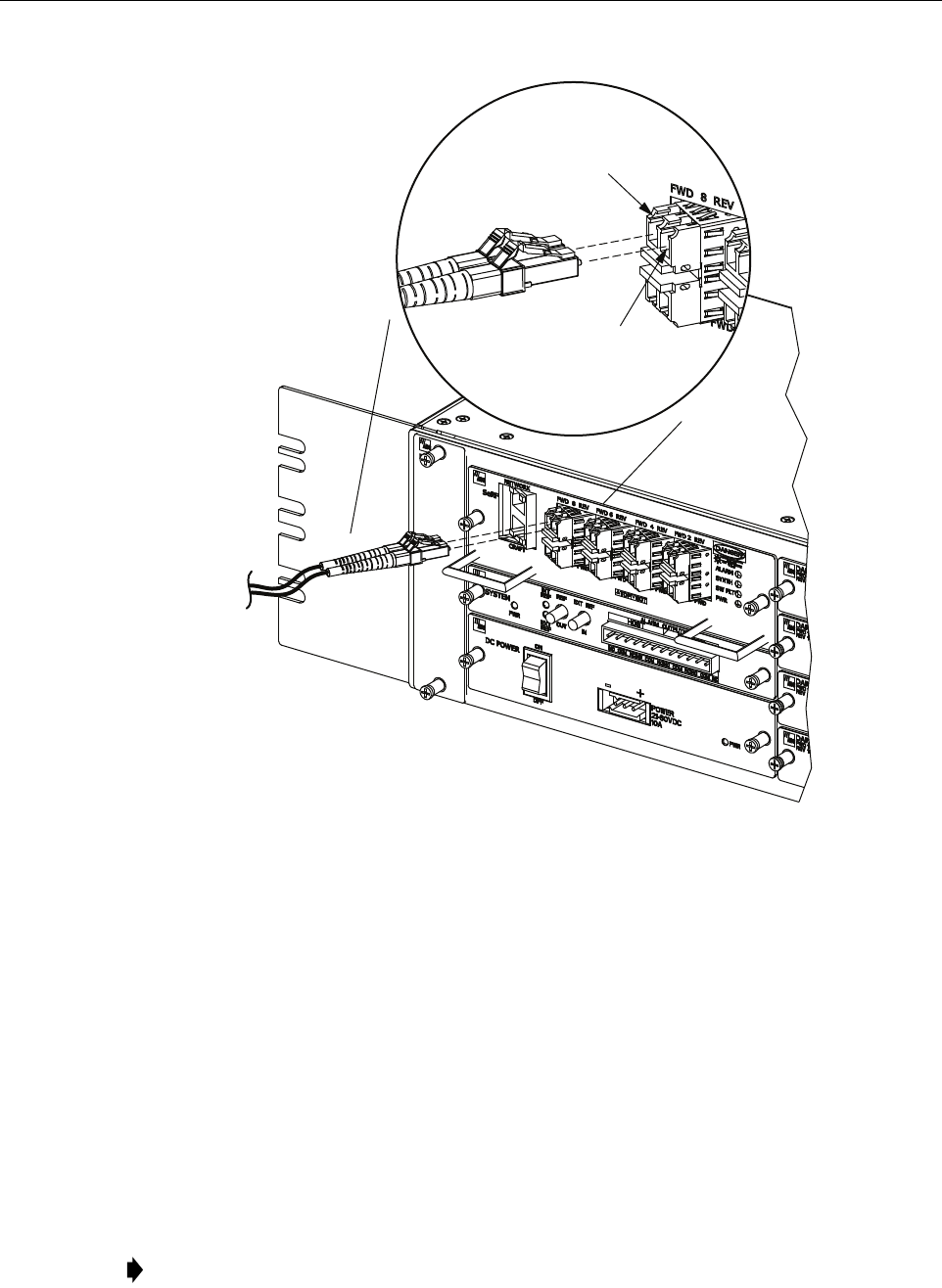
5. Insert each patch cord connector into the appropriate optical port as shown in Figure 13
and as specified by the following:
PORT 1 FWD - Forward path patch cord
PORT 1 REV - Reverse path patch cord
6. Route the patch cords from the HU to the fiber distribution panel.
7. At the fiber distribution panel, identify the OSP cable optical fiber terminations that
correspond to the forward and reverse paths.
8. Remove the dust caps from the OSP cable optical fiber adapters and from the patch cord
connectors.
9. Clean each patch cord connector (follow patch cord supplier’s recommendations) and then
mate the connector with the appropriate OSP cable adapter.
Danger: This equipment uses a Class 1 Laser according to FDA/CDRH rules. Laser radiation
can seriously damage the retina of the eye. Do not look into the ends of any optical fiber. Do not
look directly into the optical transmitter of any unit or exposure to laser radiation may result.
An optical power meter should be used to verify active fibers. A protective cap or hood MUST
be immediately placed over any radiating transmitter or optical fiber connector to avoid the
potential of dangerous amounts of radiation exposure. This practice also prevents dirt particles
from entering the connector.
Note: To protect the optical receivers, insert a 15 dB attenuator in each optical path. When
the system is turned-up and tested, the attenuator may be resized or removed.
Caution:
Improper handling can damage fiber optic cables. Do not bend fiber optic cable more
sharply than the minimum recommended bend radius specified by the cable manufacturer. Do not
apply more pulling force to the cable than specified.
Note: The HU optical adapters are angled to the left. Therefore, always route patch cords
to the HU from the left side of the rack. Routing patch cords to the HU from the right may
exceed the bend radius limitations for the optical fiber.
ADCP-75-348 • Issue 1 • 04/2008
Page 19
© 2008, ADC Telecommunications, Inc.
Figure 13. Fiber Optic Cable Connections To Host Unit
10. Repeat this procedure for the remaining SeRF SFPs in the HU.
11. Store any excess patch cord slack at the fiber distribution panel or storage panel.
6.8.2 Optical Connections For Systems With a WDM
Use the following procedure to connect the optical fibers when a WDM module is installed with
the HU:
1. Obtain a patch cord that is of sufficient length to reach from the WDM module to the fiber
distribution panel.
2. Remove the dust cap from WDM Port or Port 4 on the WDM module and from the patch
cord connector that will be connected to the WDM module.
Note: WDM module ports are labeled FWD, REV, TEST, and WDM.
22410 -A
PORT 8 FWD
(FORWARD PATH)
PORT 8 REV
(REVERSE PATH)
ADCP-75-348 • Issue 1 • 04/2008
Page 20
© 2008, ADC Telecommunications, Inc.
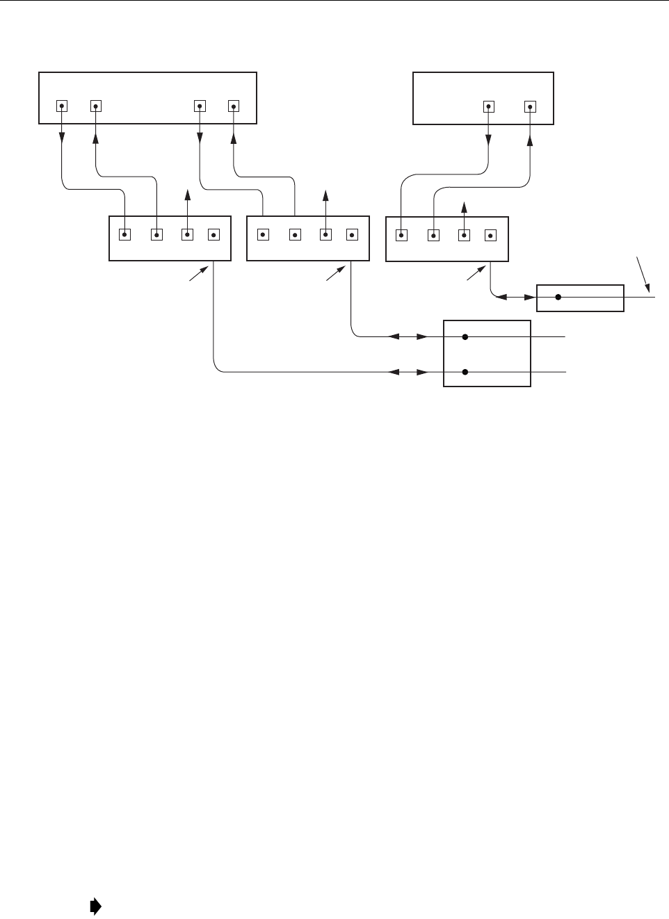
Figure 14. Fiber Optic Connections To WDM Module
3. Clean the patch cord connector (follow patch cord supplier’s recommendations).
4. Insert the connector into the WDM module optical WDM port (port 4).
5. Route the patch cord from the WDM to the fiber distribution panel or storage panel.
6. Identify the OSP cable optical fiber termination that corresponds to the RU.
7. Remove the dust cap from the OSP cable optical adapter and from the patch cord
connector.
8. Clean the patch cord connector (follow patch cord supplier’s recommendations) and then
mate the connector with the appropriate OSP cable adapter.
9. Store any excess patch cord slack at the fiber distribution panel.
10. Obtain two patch cords that are of sufficient length to reach from the WDM module to the HU.
11. Designate one of the patch cords as the forward path link and the other as the reverse
path link and attach an identification label or tag next to the connector.
12. Remove the dust caps from the HU SeRF SFP optical ports and from the patch cord
connectors that will be connected to the SeRF SFP optical ports.
13. Clean each pigtail connector (follow the procedures provided with the WDM module) and
then insert the connector into the appropriate optical port on the HU as shown in Figure 13
and as diagramed in Figure 14.
Note: To protect the optical receivers, insert a 15 dB attenuator in each optical path. When
the system is turned-up and tested, the attenuator may be resized or removed.
FIBER DISTRIBUTION
PANEL (FDP)
X
X
HOST UNIT 1
PORT 8
FWD
PORT 8
REV
REVERSE
PATH
FORWARD
PATH
WAVELENGTH
DIVISION
MULTIPLEXERS
1234
PORT 1
FWD
PORT 1
REV
HOST UNIT 2
REVERSE
PATH
FORWARD
PATH
22416-A
TO/FROM
REMOTE UNIT 1
TO/FROM
REMOTE UNIT 1
HOST UNIT 1
(BI-DIRECTIONAL FIBER
LINK WITH REMOTE UNIT)
HOST UNIT 1
(BI-DIRECTIONAL FIBER
LINK WITH REMOTE UNIT)
PORT 1
FWD
PORT 1
REV
REVERSE
PATH
FORWARD
PATH
1234
TESTTEST
1234
TEST
FIBER DISTRIBUTION
PANEL (FDP)
X
TO/FROM
REMOTE UNIT 2
HOST UNIT 2
(BI-DIRECTIONAL FIBER
LINK WITH REMOTE UNIT)
ADCP-75-348 • Issue 1 • 04/2008
Page 21
© 2008, ADC Telecommunications, Inc.
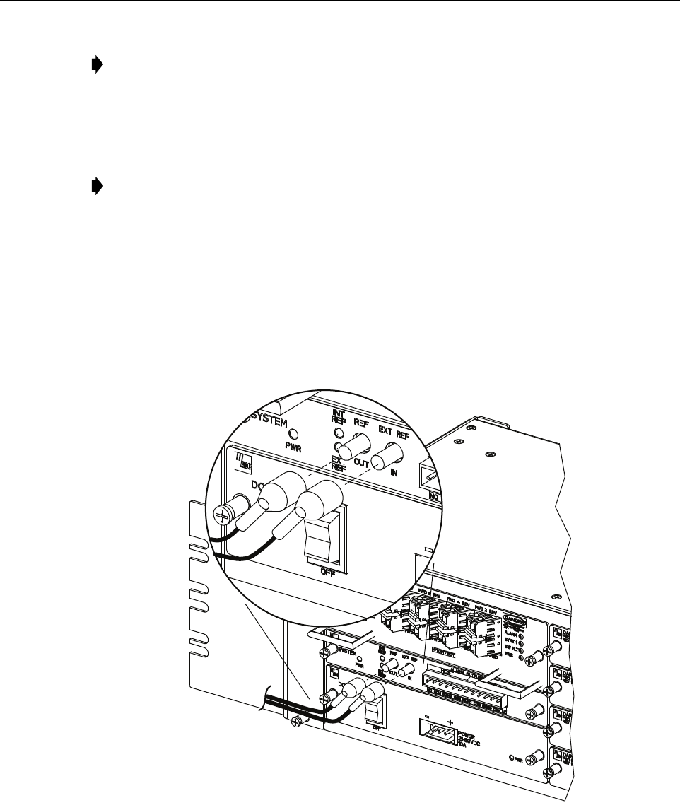
6.9 EXT REF Connections
EXT REF connections between multiple HU’s is supported through two QMA type female
connectors mounted on the System card. One of the jacks is designated as the IN port and the
other jack is designated as the OUT port. The EXT REF interface allows HU’s to be connected
together (in daisy-chain fashion) and clocked through a single source. Use the following
procedure to connect EXT REF interface cables between multiple HU’s:
1. Connect one end of the EXT REF interface cable (accessory) to either the IN or OUT port
on HU #1 as shown in Figure 15.
Figure 15. EXT REF Connections
2. Route the EXT REF interface cable to HU #2 and connect the cable’s free end to the port
that is the logical opposite of the EXT REF interface connection at HU #1.
Note: The HU SeRF SFP optical adapters are angled to the left. Therefore, pigtails should
always be routed to the HU from the left side of the rack. Routing pigtails to the HU from
the right side of the rack may exceed the bend radius limitations for the optical fiber.
Note: When using the 10 MHz external reference clock the signal must be connected to
the HU before enabling the clock source in the software.
22407-A
ADCP-75-348 • Issue 1 • 04/2008
Page 22
© 2008, ADC Telecommunications, Inc.
3. If a third HU will be connected to the network, connect a second EXT REF interface cable
to the remaining network port on HU #2.
4. Route the second EXT REF interface cable to HU #3 and connect the cable’s free end to
the port that is the logical opposite of the EXT REF interface connection at HU #2.
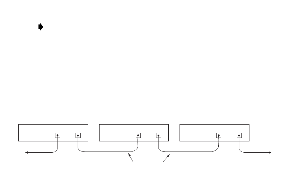
5. Repeat steps 3 and 4 for each additional HU that is added to the network. A diagram of
typical EXT REF interface connections is shown in Figure 16.
Figure 16. Configuring EXT REF Connections with Multiple Host Units
6.10 Computer Connection (CRAFT)
The service interface connection between the HU and the computer is supported by a single RJ-
45 connector. Use the following procedure to install the service interface cable:
1. Connect one end of the service interface cable (accessory) to the CRAFT port as shown in
Figure 17.
2. Route the service interface cable to the computer and connect the free end of the cable to
the computer’s port. Refer to the user manual provided with the computer to locate and
configure the specified port.
Note: Connect OUT to IN and IN to OUT. If connected to a EXT REF OUT port at HU
#1, connect to the EXT REF IN port at HU #2. If connected to a EXT REF IN port at HU
#1, connect to a EXT REF OUT port at HU #2.
HOST UNIT 3 HOST UNIT 2 HOST UNIT 1
OUT EXT IN NET IN NET OUT NET IN NET OUT
22414-A
COAXIAL
INTERFACE CABLES
TO NEXT HOST UNIT
(NOTE: LAST HOST HAS NO
CONNECTION AT EXT OUT)
OUT EXT IN OUT EXT IN
REF CLOCK
INPUT
ADCP-75-348 • Issue 1 • 04/2008
Page 23
© 2008, ADC Telecommunications, Inc.
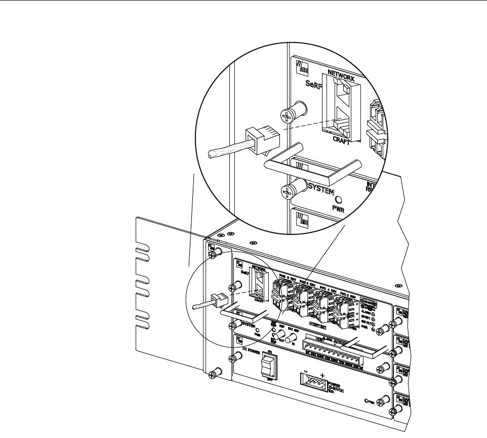
Figure 17. Craft Interface and Network Interface Connections
6.11 Network Connection
A network connection between the HU and the network is used to monitor and configure the
FlexWave URH system through a single IP connection. Use the following procedure to install
the network interface cable:
1. Connect one end of the cable (accessory) to the NETWORK port as shown in Figure 17.
2. Route the cable to the computer and connect the free end of the cable to the computer’s
port. Refer to the user manual provided with the computer to locate and configure the
specified port.
22403-A
RJ-45
CONNECTOR
DETAIL
ADCP-75-348 • Issue 1 • 04/2008
Page 24
© 2008, ADC Telecommunications, Inc.
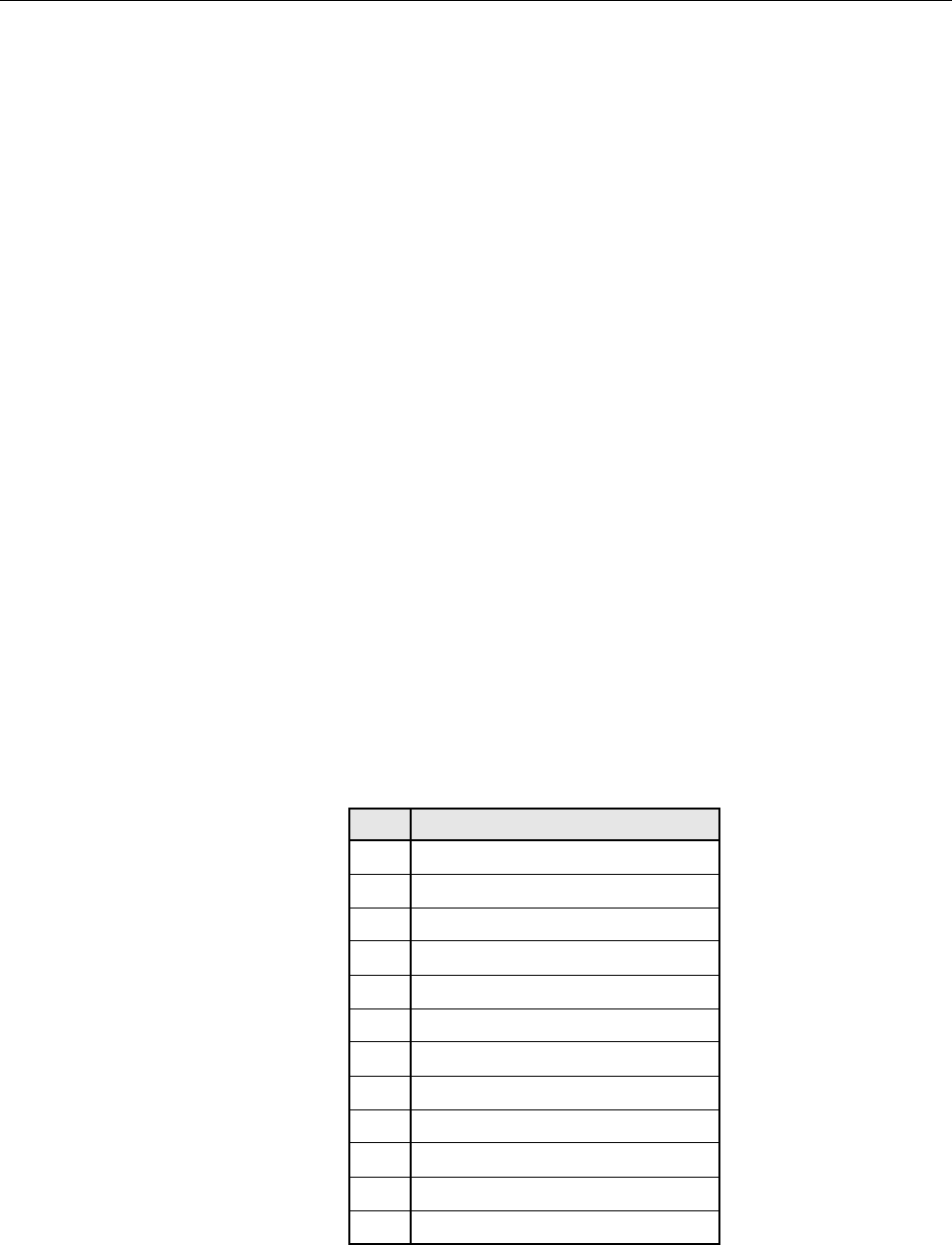
6.12 System Alarm System Connections
The alarm interface between the HU and an alarm system is supported by twelve-terminal plug
(with screw-type terminals) that connects to a receptacle mounted on the HU System card front
panel. The terminal plug provides connections to normally open (NO) and normally closed
(NC) dry type alarm contacts for both major and minor alarms. A category 3 or 5 cable is
typically used to connect the HU System card to the alarm system. Use the following procedure
to install the alarm wiring and connect it to the HU:
1. Obtain the required length of category 3 or 5 cable.
2. Route the cable between the HU System card and the alarm system (if not already routed)
and then cut to the required length. Allow sufficient slack for dressing and organizing the
cable at the HU.
3. Strip back the outer cable sheath and insulation to expose the wires at both ends of the
cable and strip back 0.2 inches (5 mm) of insulation from each wire.
4. Connect the Major alarm wire pair to the MAJOR COM/NC or MAJOR COM/NO
terminals (whichever is required by the alarm system) on the HU System card alarm
terminal connector (supplied with HU System card) as shown in Figure 18.
5. Connect the Minor alarm wire pair to the MINOR COM/NC or MINOR COM/NO
terminals (whichever is required by the alarm system) on the HU System card alarm
terminal connector (see Figure 18 and Table 4).
6. Connect the Major and Minor alarm wire pairs to the appropriate terminals on the external
alarm system.
7. Dress and secure cable per standard industry practice.
Table 4. System Card Alarm Pin Designations
PIN DESCRIPTION
1Host Minor Normally Closed
2Host Minor Common
3Host Minor Normally Open
4Host Major Normally Closed
5Host Major Common
6Host Major Normally Open
7Remote Minor Normally Closed
8Remote Minor Common
9Remote Minor Normally Open
10 Remote Major Normally Closed
11 Remote Major Common
12 Remote Major Normally Open
ADCP-75-348 • Issue 1 • 04/2008
Page 25
© 2008, ADC Telecommunications, Inc.
Figure 18. Alarm System Connections
6.13 Power Connections
HU is powered by a modular power supply located on the lower left side of the chassis. An On/
Off switch is provided on the HU power supply module front panel.
6.13.1 DC Power Connections
The HU is powered by ± 20 to 60 VDC power (nominal ± 24 or ± 48 VDC), install DC Power
Supply in the lower left side of the HU chassis. Secure in place by turning screws clock-wise
until tight.
22406-A
PIN 12
PIN 1

ADCP-75-348 • Issue 1 • 04/2008
Page 26
© 2008, ADC Telecommunications, Inc.
A three position terminal block is provided for connecting the power wires. The power is fed to
the HU Power Supply module through a connector located on the front of the unit. Power to the
HU must be supplied through a fuse panel such as the 20 position PowerWorx GMT Fuse Panel
(available separately) and the power must be protected with a 15 Amp GMT fuse.
Use the following procedure to install the power wiring:
1. Obtain the items listed below:
• Wire stripper and screwdriver
•Wire,
#18 AWG (1.00 mm) red and black insulated copper wire
. Recommended wire size
for the power leads, when fused in the same bay.
2.
Turn power switch on power supply OFF.
3. Connect the wires to the designated terminals on the fuse panel.
4. Dress and secure the wires to the rack following local practice. Route wiring away from
sharp edges and secure in place to prevent chaffing and provide strain relief.
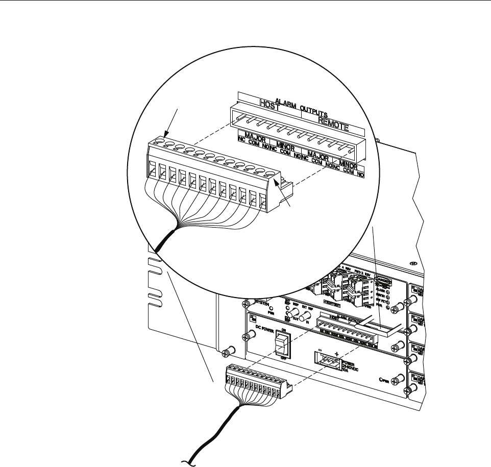
5. Route the wires to the terminal block (Figure 19) on the HU Power Supply and cut them to
length, allowing sufficient length for termination.
6. Loop both power wires around and through the Ferrite as shown in Figure 19.
7. Strip 1.27 cm (0.5 inch) of insulation from the end of each wire.
8. Insert one end of each wire into the terminal block, one into + and the other into the – position.
9. The terminal block must plug into the three-pin receptacle on the front of the HU Power
Supply.
10. Install fuses in the fuse panel. Update office records as required.
11.
Turn power switch on power supply ON.
12. The procedure for checking the voltage level and verifying that the HU is ready to power up
is provided in the applicable System Operation and Maintenance Manual (see Related
Publications section).
Note: All DC input wiring should be routed away from any sharp edges and properly
secured in place to prevent chafing and to provide strain relief. This may be achieved by
tie-wrapping wires to the rack frame or by a similar means.
Note: When connecting the equipment to the supply circuit, be sure to check equipment
nameplate ratings to avoid overloading circuits which may cause damage to over-current
protection devices and supply wiring.
ADCP-75-348 • Issue 1 • 04/2008
Page 27
© 2008, ADC Telecommunications, Inc.
Figure 19. DC Power Connections
6.14 Installation Complete
When the installation is complete, refer to the applicable System User Manual (see Related
Publications section) for the system turn-up and test procedures.
7 MAINTENANCE
This section provides the HU maintenance procedures. Refer to this section when scheduled
maintenance is required. The fault isolation and troubleshooting procedures are provided in the
applicable System Operation and Maintenance Manual (see Related Publications section). Host
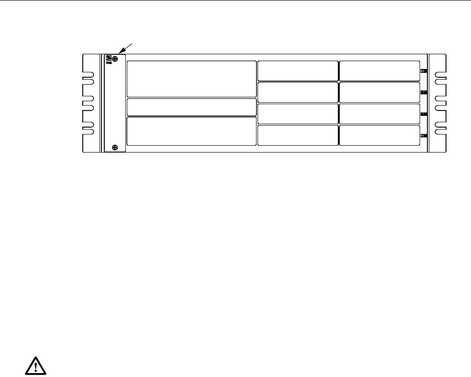
Unit card locations are shown in Figure 20.
22405-A
FERRITE
ADCP-75-348 • Issue 1 • 04/2008
Page 28
© 2008, ADC Telecommunications, Inc.
Figure 20. Host Unit Card Locations
7.1 Host Unit Fan Replacement Procedure
The HU is equipped with a fan assembly consisting of two cooling fans which is located on the
left side of the HU enclosure. The cooling fans blow cool air into the enclosure. Heated air is
exhausted through the vent openings on the right side of the enclosure. Replacement of fan
assembly does not require that the HU be turned off. The recommended replacement interval is
60 months. Use the following procedure to remove and replace the HU cooling fans:
1. Before working on the HU or handling a fan, slip on an Electro-Static Discharge (ESD)
wrist strap and connect the ground wire to an earth ground source. Wear the ESD wrist
strap while completing each section of the fan installation procedure.
2. Notify the NOC or alarm monitoring system operator that the fan is being replaced.
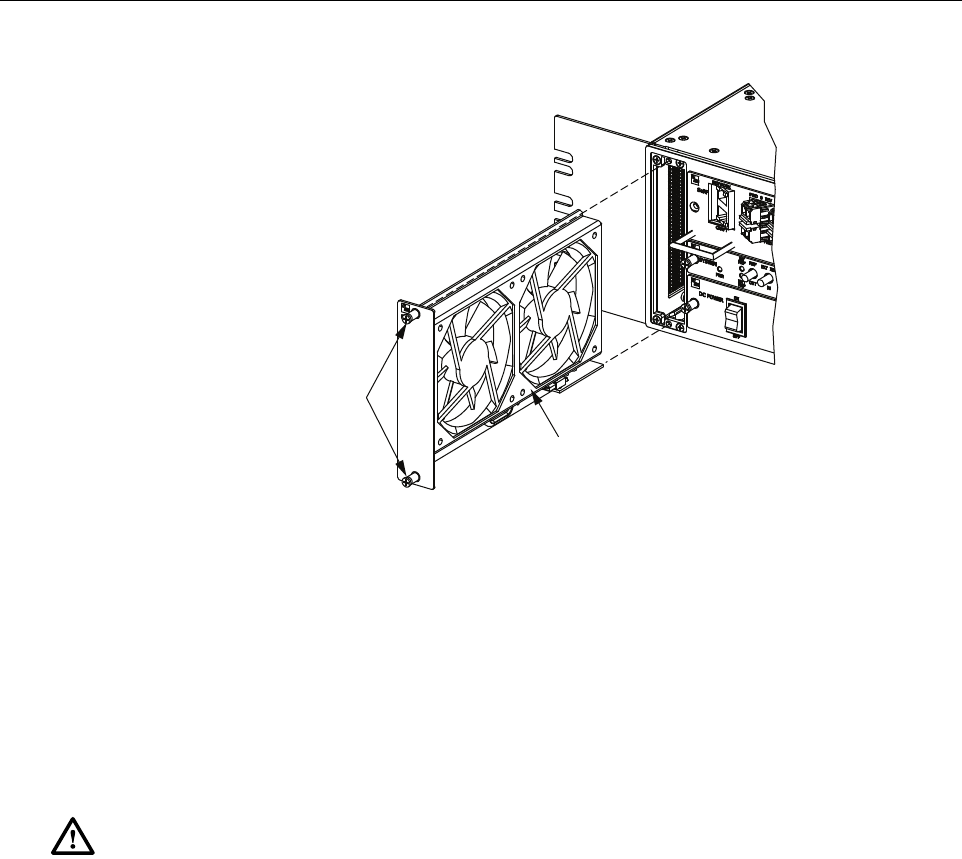
3. Loosen the two thumb screws that secure the fan/grill assembly to the front of the HU
enclosure as shown in Figure 21.
4. Carefully withdraw the fan/grill assembly from the enclosure.
5. Slide the new fan assembly into the HU chassis until it is firmly seated.
6. Secure the fan/grill assembly to the front of the enclosure (see Figure 21) using the two
screws loosened in Step 3.
7. Verify that the fans run properly following power-up.
8. Notify the NOC or alarm monitoring system operator that the fans are back in operation.
Warning: Electronic components can be damaged by static electrical discharge. To prevent
ESD damage, always wear an ESD wrist strap when working on the HU and when handling
electronic components.
SeRF CARD
SYSTEM CARD
POWER SUPPLY
DART CARD
DART CARD
DART CARD
DART CARD
DART CARD
DART CARD
DART CARD
DART CARD
FAN ASSEMBLY
22402-A
ADCP-75-348 • Issue 1 • 04/2008
Page 29
© 2008, ADC Telecommunications, Inc.
Figure 21. Host Unit Fan Assembly Removal
7.2 Power Supply Replacement Procedure
Removing the power supply will disable the Host Unit and interrupt service. Notify the NOC or
alarm monitoring system operator that the system will be out of service for a period of time.
1. Before working on the HU or handling a power supply, slip on an Electro-Static Discharge
(ESD) wrist strap and connect the ground wire to an earth ground source. Wear the ESD
wrist strap while completing each section of the fan installation procedure.
2. Turn power switch to the OFF position.
3. Unplug power plug by applying pressure to the left and right side of the connector and
pulling it straight out.
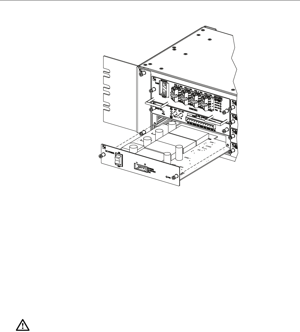
4. Loosen the two thumb screws that secure the Power Supply to the front of the HU
enclosure. See Figure 22.
5. Carefully withdraw the Power Supply from the enclosure.
6. Slide replacement Power Supply into the HU chassis until it is firmly seated.
7. Secure the Power Supply to the front of the enclosure using the two thumb screws
loosened in Step 4.
8. Plug power plug into the power connector on the front of the Power Supply. Make certain
that it is fully seated.
Warning: Electronic components can be damaged by static electrical discharge. To prevent
ESD damage, always wear an ESD wrist strap when working on the HU and when handling
electronic components.
22396-A
FAN
ASSEMBLY
THUMB
SCREWS
ADCP-75-348 • Issue 1 • 04/2008
Page 30
© 2008, ADC Telecommunications, Inc.
Figure 22. Power Supply Replacement
9. Turn power switch to the ON position.
10. Notify the NOC or alarm monitoring system operator that the system is back in operation.
7.3 System Card Replacement Procedure
System Card can be replaced without disrupting service. If the EXT REF is being used
communications to other HU’s will be disrupted.
1. Before working on the HU or handling a System Card, slip on an Electro-Static Discharge
(ESD) wrist strap and connect the ground wire to an earth ground source. Wear the ESD
wrist strap while completing each section of the fan installation procedure.
2. Notify the NOC or alarm monitoring system operator that the System Card is being
replaced.
3. If used, disconnect EXT REF cables from the front of the System Card.
4. Remove alarm plug from the front of the System Card by pressing on the lock tabs.
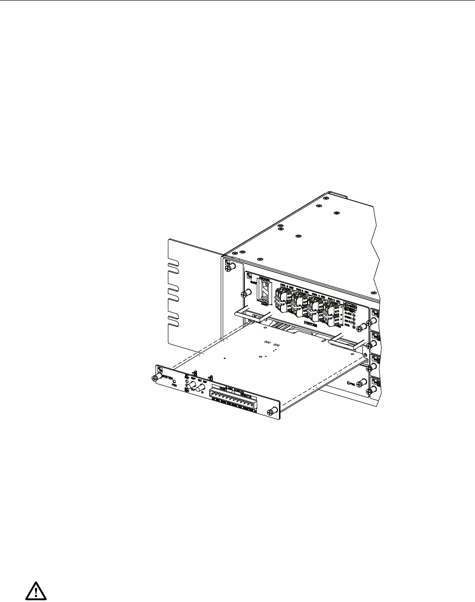
5. Loosen the two thumb screws that secure the System Card to the front of the HU
enclosure. See Figure 23.
Warning: Electronic components can be damaged by static electrical discharge. To prevent
ESD damage, always wear an ESD wrist strap when working on the HU and when handling
electronic components.
22400-A
ADCP-75-348 • Issue 1 • 04/2008
Page 31
© 2008, ADC Telecommunications, Inc.
6. Carefully withdraw the System Card from the enclosure.
7. Slide replacement System Card into the HU chassis until it is firmly seated.
8. Secure the System Card to the front of the enclosure using the two thumb screws loosened
in Step 5.
9. If used, connect EXT REF cables to the front of the System Card.
10. Plug alarm plug into the connector on the System Card.
11. On the Power Supply turn the power switch OFF and then back ON to reset the System Card.
12. Notify the NOC or alarm monitoring system operator that the system is back in operation.
Figure 23. System Card Replacement
7.4 SeRF Card Replacement Procedure
Removing the SeRF Card will disable the Host Unit and interrupt service. Notify the NOC or
alarm monitoring system operator that the system will be out of service for a period of time.
1. Before working on the HU or handling a SeRF Card, slip on an Electro-Static Discharge
(ESD) wrist strap and connect the ground wire to an earth ground source. Wear the ESD
wrist strap while completing each section of the fan installation procedure.
Warning: Electronic components can be damaged by static electrical discharge. To prevent
ESD damage, always wear an ESD wrist strap when working on the HU and when handling
electronic components.
22398-A
ADCP-75-348 • Issue 1 • 04/2008
Page 32
© 2008, ADC Telecommunications, Inc.
2. Remove Network and Craft RJ-45 plugs from the front of the SeRF Card.
3. Remove fiber pigtails from the SFP’s. Note the location of the pigtails.
4. Loosen the two thumb screws that secure the System Card to the front of the HU
enclosure. See Figure 24.
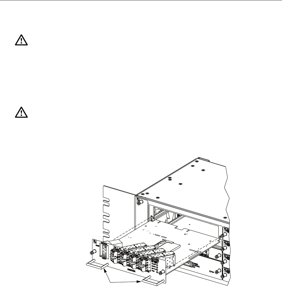
Figure 24. SeRF Card Replacement
5. Use the two handles to carefully withdraw the SeRF Card from the enclosure.
6. Slide replacement SeRF Card into the HU chassis until it is firmly seated.
7. Secure the SeRF Card to the front of the enclosure using the two thumb screws loosened in
Step 4.
8. If necessary install new SFP’s or remove them from the SeRF card removed in Step 5 and
install them in the new SeRF Card.
9. Plug fiber pigtails back into the SFP’s.
Danger: This equipment uses a Class 1 Laser according to FDA/CDRH rules. Laser radiation
can seriously damage the retina of the eye. Do not look into the ends of any optical fiber. Do not
look directly into the optical transmitter of any unit or exposure to laser radiation may result.
An optical power meter should be used to verify active fibers. A protective cap or hood MUST
be immediately placed over any radiating transmitter or optical fiber connector to avoid the
potential of dangerous amounts of radiation exposure. This practice also prevents dirt particles
from entering the connector.
Caution:
Improper handling can damage fiber optic cables. Do not bend fiber optic cable more
sharply than the minimum recommended bend radius specified by the cable manufacturer. Do not
apply more pulling force to the cable than specified.
22397-A
HANDLES

ADCP-75-348 • Issue 1 • 04/2008
Page 33
© 2008, ADC Telecommunications, Inc.
10. Plug Network and Craft RJ-45 plugs into the connector on the SeRF Card. Make certain
the pigtails are inserted in the correct SFP.
11. Notify the NOC or alarm monitoring system operator that the system is back in operation.
7.5 DART Card Replacement/Installation Procedure
Each DART Card provides an interface between the SeRF and the Power Amplifier they are
spectrum specific. When additional service is needed another DART Card can be added to the
HU and the corresponding cover added to a Remote Unit. Individual DART Cards may be
replaced without disrupting service to the entire remote system. Only the RF spectrum of the
DART Card being removed is affected. Refer to Figure 25.
7.5.1 Replacement
1. Before working on the HU or handling a DART Card, slip on an Electro-Static Discharge
(ESD) wrist strap and connect the ground wire to an earth ground source. Wear the ESD
wrist strap while completing each section of the fan installation procedure.
2. Notify the NOC or alarm monitoring system operator that the DART Card is being
replaced.
3. Disconnect REF IN and OUT cables from the front of the DART Card.
4. Loosen the two thumb screws that secure the DART Card to the front of the HU enclosure.
5. Carefully withdraw the DART Card from the enclosure.
6. Slide replacement DART Card into the HU chassis until it is firmly seated.
7. Secure the DART Card to the front of the enclosure using the two thumb screws loosened
in Step 4.
8. Connect REF IN and OUT cables to the front of the DART Card.
9. Notify the NOC or alarm monitoring system operator that the system is back in operation.
Warning: Electronic components can be damaged by static electrical discharge. To prevent
ESD damage, always wear an ESD wrist strap when working on the HU and when handling
electronic components.
ADCP-75-348 • Issue 1 • 04/2008
Page 34
© 2008, ADC Telecommunications, Inc.
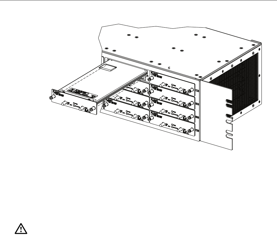
Figure 25. DART Card Replacement/Installation
7.5.2 Install New DART Card
1. Before working on the HU or handling a DART Card, slip on an Electro-Static Discharge
(ESD) wrist strap and connect the ground wire to an earth ground source. Wear the ESD
wrist strap while completing each section of the fan installation procedure.
2. Notify the NOC or alarm monitoring system operator that another DART Card is being
added the HU.
3. Determine slot location of the new DART Card. Remove blank panel from the front of the
HU.
4. Slide DART Card into the HU chassis until it is firmly seated.
5. Secure the DART Card to the front of the enclosure using the two thumb screws.
6. Obtain the required lengths of high performance, flexible, low loss 50-ohm coaxial
communications cable (RG-400 or equivalent) for all coaxial connections.
7. Route the forward and reverse path coaxial cables between the HU and the BTS interface
(per system design plan) and cut to the required length. Allow sufficient slack for dressing
and organizing cables at the HU and for installing an external attenuator in the forward
path link.
8. Terminate each cable with an QMA-type male connector following the connector
supplier’s recommendations.
9. If required, install an external attenuator in the forward path.
Warning: Electronic components can be damaged by static electrical discharge. To prevent
ESD damage, always wear an ESD wrist strap when working on the HU and when handling
electronic components.
22401-A

ADCP-75-348 • Issue 1 • 04/2008
Page 35
© 2008, ADC Telecommunications, Inc.
10. Connect the forward path cable to the FWD RF IN connector on the HU DART front
panel as shown in Figure 12.
11. Connect the reverse path cable to the REV RF OUT connector on the HU DART front
panel (see Figure 12).
12. Dress and secure cables at the right side of the HU.
13. Complete all remaining coaxial connections as specified in the system design plan.
14. Notify the NOC or alarm monitoring system operator that the DART Card is in operation.
Note: The composite forward path RF signal level at the HU must be between –25 and
+5 dBm. Do not connect the forward path cable until the composite forward path RF
signal level is measured and the amount of external attenuation required is determined.
ADCP-75-348 • Issue 1 • 04/2008
Page 36
© 2008, ADC Telecommunications, Inc.
8 CUSTOMER INFORMATION AND ASSISTANCE
13944-Q
Contents herein are current as of the date of publication. ADC reserves the right to change the contents
without prior notice. In no event shall ADC be liable for any damages resulting from loss of data,
loss of use, or loss of profits and ADC further disclaims any and all liability for indirect, incidental,
special, consequential or other similar damages. This disclaimer of liability applies to all products,
publications and services during and after the warranty period.
REPRINTS:
www.adc.com/manuals
PDF copies of manuals are available
for downloading at the following link:
PRODUCT INFORMATION AND TECHNICAL ASSISTANCE:
connectivity.tac@adc.com
wireless.tac@adc.com
euro.tac@adc.com
asiapacific.tac@adc.com
ADCP Number:
WRITE:
ADC Telecommunications (S’PORE) PTE, LTD;
100 Beach Road, #18-01, Shaw Towers.
Singapore 189702.
ADC Telecommunications, INC
PO Box 1101,
Minneapolis, MN 55440-1101, USA
ADC European Customer Service, INC
Belgicastraat 2,
1930 Zaventem, Belguim
PHONE:
U.S.A. or CANADA
Sales: 1-800-366-3891
Extension 73000
Technical Assistance: 1-800-366-3891
Connectivity Extension: 73475
Wireless Extension: 73476
EUROPE
Sales Administration: +32-2-712-65 00
Technical Assistance: +32-2-712-65 42
EUROPEAN TOLL FREE NUMBERS
Germany: 0180 2232923
UK: 0800 960236
Spain: 900 983291
France: 0800 914032
Italy: 0800 782374
ASIA/PACIFIC
Sales Administration: +65-6294-9948
Technical Assistance: +65-6393-0739
ELSEWHERE
Sales Administration: +1-952-917-3000
Technical Assistance: +1-952-917-3475
75-348