ADC Telecommunications FWURHSMR FlexWave™ URH - SMR User Manual User guide
ADC Telecommunications Inc FlexWave™ URH - SMR User guide
User guide
Mailing Address: P.O. Box 1101, Minneapolis, Minnesota 55440-1101
World Headquarters: Minneapolis, Minnesota USA +1.952.938.8080 www.adc.com
Hardware Installation – FlexWaveTM URH - Preliminary
FlexWave™ URH
Operation and Maintenance Manual - Preliminary
PRODUCT DESCRIPTION
This publication provides basic information about the FlexWave™ URH installation.
The FlexWave URH provides the same functionality as the ADC Wireless family of distributed
antenna systems (DAS). However, the URH platform implements three single band DAS
system capability into one single chassis. The system is comprised of a host and remote
chassis with a fiber optic interface. The host chassis is intended for central office equipment
enclosure/indoor use. This remote chassis is functional for indoor and outdoor installation.
The remote chassis provides the degree of protection specified by NEMA 6 and IP67 as
defined by IEC Publication 60529.
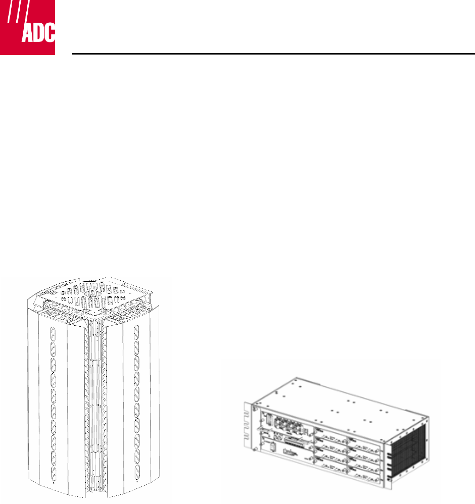
INSTALLATION OVERVIEW
REMOTE ENCLOSURE HOST ENCLOSURE

Mailing Address: P.O. Box 1101, Minneapolis, Minnesota 55440-1101
World Headquarters: Minneapolis, Minnesota USA +1.952.938.8080 www.adc.com
Mounting
The FlexWave™ URH host chassis is 19/23 inch equipment rack mountable requiring
3 RU spacing.
The Flexwave URH remote chassis has a mounting bracket provided with each unit.
The mounting bracket is banded to the pole with three 1.0” wide stainless steel bands. The
chassis is then hung from the bracket by means of protrusions and keyhole slots. Once the
chassis is in place, it is further secured to the mounting bracket with two 7/16” stainless
steel hex bolts.

Mailing Address: P.O. Box 1101, Minneapolis, Minnesota 55440-1101
World Headquarters: Minneapolis, Minnesota USA +1.952.938.8080 www.adc.com
SPECIFICATIONS
RF Specification
Supported Frequency Blocks 1-3 per Remote Unit; 1-8 per Host Unit
Bandwidth 1.5 to 35 MHz non-contiguous
Frequency Band Supported 800 Cellular, E-SMR 800/900, 1900 PCS,
1800/2100 AWS (First Release)
700, 1800 & 2500 MHz (Future Releases)
Digital Simulcast Up to 8:1 Single Host (can daisy chain Host for higher simulcast)
Diversity Receive Yes (Optional)
Propagation Delay
System Delay <12 microseconds
Delay Management Digital (Manual or Automatic)
Noise Figure
Noise Figure <5 dB
Input IP3 >-8 dBm
Optical Specifications
Optical Budget 10 dB (Standard); 26 dB (Optional)
Digital Transport Rate 3.072 Gbps
Output Power
Output Power per Band 38 dBm (6.5 Watts) Cell/SMR - October '07
43 dBm (20 Watts) PCS – November ‘07
43 dBm (20 Watts) AWS – December ‘07
43 dBm (20 Watts) Cell & SMR – Q2 ‘08
39 dBm (8 Watts) WiMAX – Q2 ‘08
General Specifications
Remote Unit Outside Ambient Temp Rating -40°C to +50°C
Storage Temperature -40°C to +70°C
Humidity 10% to 90% non-condensing
Lightning Protection 20kA IEC 1000-45 8/30 μs Waveform
Remote Unit
Enclosure IP-65
Mounting Wall, Pole
Dimensions 16.45” x 15.6” x 29.38”
Weight ≤200 Pounds (No component greater than 80 pounds)
Volume 3.66 cubic feet
Cooling Passive Convection
Optical Connectors Sealed ProAx
Impedance 50 Ohm
Host Unit
Mounting 19- and 23-inch rack
Rack Units 3 Rack Units
Weight <25 Pounds
Host Unit Power Requirements
Power Source 21 to 60 VDC floating
Remote Unit Power Requirements
Power Supply 100-240 VAC
Battery Backup UPS
Element Management
Embedded EMS Yes
SNMP Based Management Yes

Mailing Address: P.O. Box 1101, Minneapolis, Minnesota 55440-1101
World Headquarters: Minneapolis, Minnesota USA +1.952.938.8080 www.adc.com
STANDARDS CERTIFICATION
FCC: This equipment complies with the applicable sections of Title 47 CFR Part 15 (Host
unit), Part 22 (800 MHz Cellular), Part 24 (1900 MHz - PCS), and Part 90 (800/900 - SMR)
IC: This equipment complies with the applicable sections of RSS-131. The term “IC:” before
the radio certification number only signifies that Industry Canada Technical Specifications
were met.
The Manufacturer's rated output power of this equipment is for single carrier operation. For
situations when multiple carrier signals are present, the rating would have to be reduced by
3.5 dB, especially where the output signal is re-radiated and can cause interference to
adjacent band users. This power reduction is to be by means of input power or gain
reduction and not by an attenuator at the output of the device.
Note: To comply with Maximum Permissible Exposure (MPE) requirements, the maximum
composite output form the antenna cannot exceed 1000 Watts ERP (Cellular and SMR), the
antenna cannot exceed 1640 Watts EIRP (PCS), and the antenna must be permanently
installed in a fixed location that provides at least 6 meters (20 feet) of separation from all
persons.
UL/CUL: This will be installed in a restricted access location. This equipment complies with
NEMA Type 6, per UL and CUL 50, Standard for Enclosures for Electrical Equipment. This
equipment provides the degree of protection specified by IP67 as defined in IEC Publication
529.
Conforms to ANSI/UL Std. 60950. Certified to CAN/CSA STD C22.2 No 60950
FDA/CDRH: This equipment uses a Class 1 LASER according to FDA/CDRH Rules. This
product conforms to all applicable standards of 21 CFR Part 1040.
Caution: Modifications not expressly approved by the party responsible for compliance
could void the user’s authority to operate the equipment.
Mailing Address: P.O. Box 1101, Minneapolis, Minnesota 55440-1101
World Headquarters: Minneapolis, Minnesota USA +1.952.938.8080 www.adc.com
AC Power Wiring Installation
A 15-foot connectorized 3-wire cable is provided for the AC power connections. The connectorized end
of the cable connects to the AC power port located on the bottom of the enclosure. The stub end of the
cable must be routed to an external junction box (not provided) for permanent connection to the AC
power system wiring. The socket outlet shall be installed near the equipment and shall be easily
accessible.
The AC power source must supply 120 or 240 VAC, 50 or 60 Hz, single-phase power through a
15 Amp circuit breaker. The AC power cable provides three wire leads for line, neutral, and
ground connections. The power cable is rated for indoor or outdoor use and must not be placed
within electrical conduit as this will impede the cooling of the cable during usage. The electrical
junction box and any conduit, wire, and fittings required must be provided by the installer.
Use the following procedure to install the AC power wiring:
1. Locate the AC power cable that is provided separately with the enclosure.
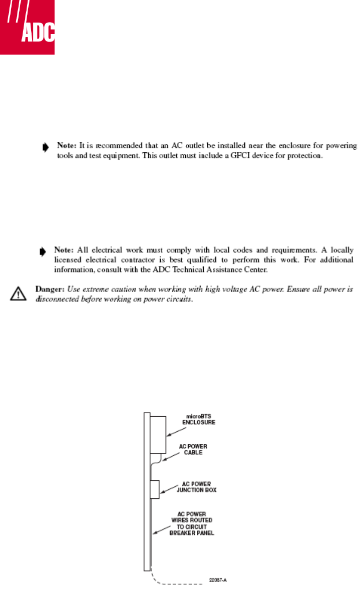
2. Route the power cable between the AC power port, located on the underside of the enclosure
and the nearest AC power junction box as shown in Figure 14. It may be necessary to install a
new junction box if an existing junction box is not available.
Figure 14. Typical AC Power Cable Routing
Mailing Address: P.O. Box 1101, Minneapolis, Minnesota 55440-1101
World Headquarters: Minneapolis, Minnesota USA +1.952.938.8080 www.adc.com
3. Secure the cable between the AC power port and the AC power junction box per local
practice. Leave sufficient slack in the cable to allow it to be easily connected and
disconnected from the AC power port.
4. Install any AC power supply wires that may be required between the AC junction box and
the AC circuit breaker box.
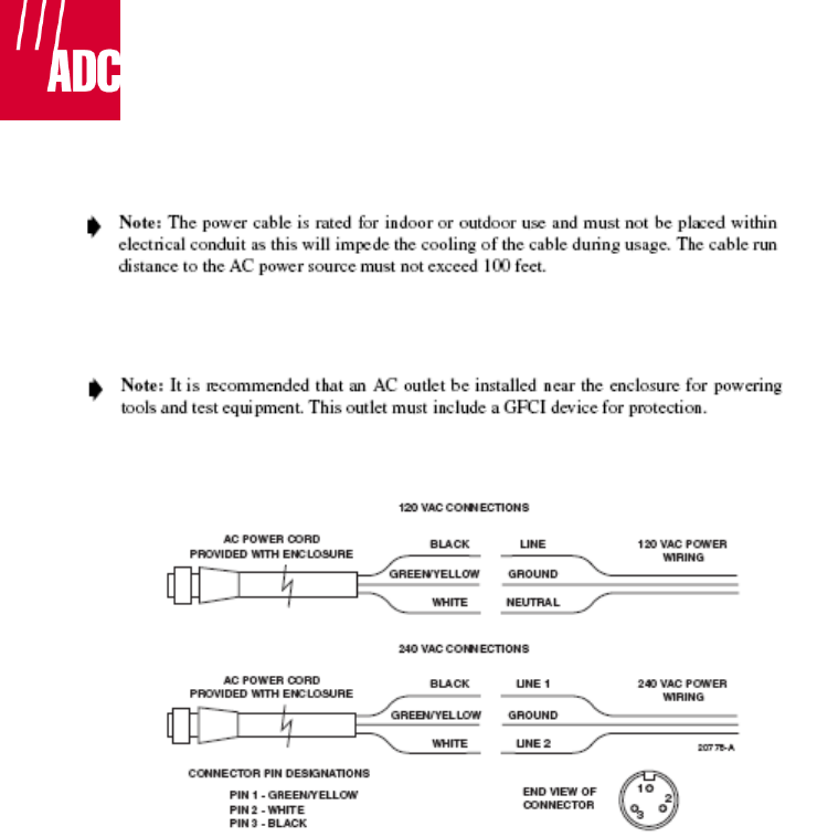
5. Connect the AC power cable wires to the AC power supply wires. Refer to Figure 15 to
identify the color code and wire designations.
Figure 15. AC Power Cable Connections
6. At the AC circuit breaker box, connect the AC power supply load wires to a 15 Amp
circuit breaker.
7. Place the circuit breaker in the ON position and then test the connectorized end of the AC
power cable for proper voltage levels and correct polarity.
8. When testing is complete, place the circuit breaker in the OFF position.
9. Remove the dust cap from the AC power port located on the bottom of the enclosure.
.
Danger: While trying to connect the AC power cable to the remote unit AC power port, it is
possible for the line terminal on the cable connector to contact the ground pin on the power
port. If the AC cable is energized, this will result in a direct short to ground for the AC power. To
avoid possible personal injury and equipment damage, always turn the AC power off before
connecting the AC power cable to the AC power port.

Mailing Address: P.O. Box 1101, Minneapolis, Minnesota 55440-1101
World Headquarters: Minneapolis, Minnesota USA +1.952.938.8080 www.adc.com
10. Connect the power cable connector to the AC power port.
11. Tighten coupling nut until the green band at the top of the connector body is visible.