ADC Telecommunications IRP0801A InterReach® picoBTS 800 MHz User Manual
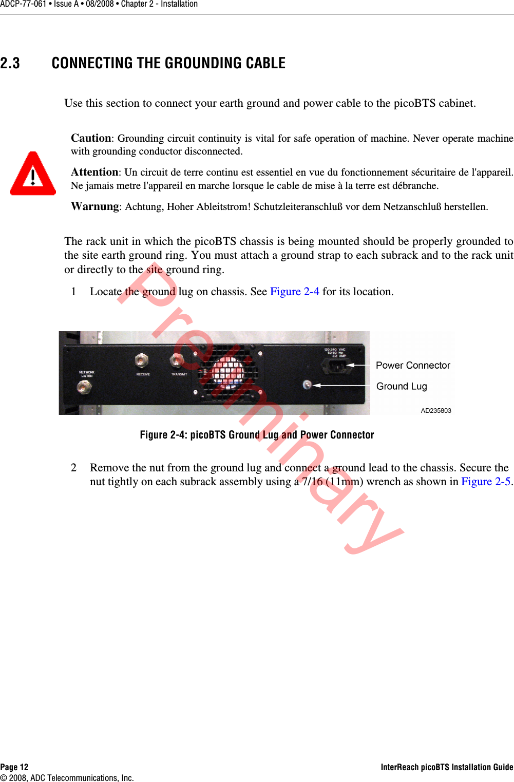
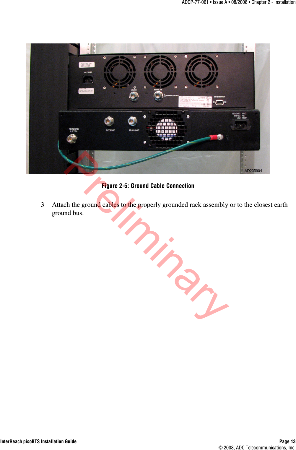
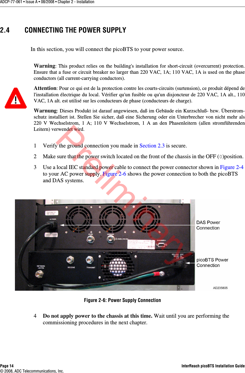
ADC Telecommunications Inc InterReach® picoBTS 800 MHz
UserManual.wiki
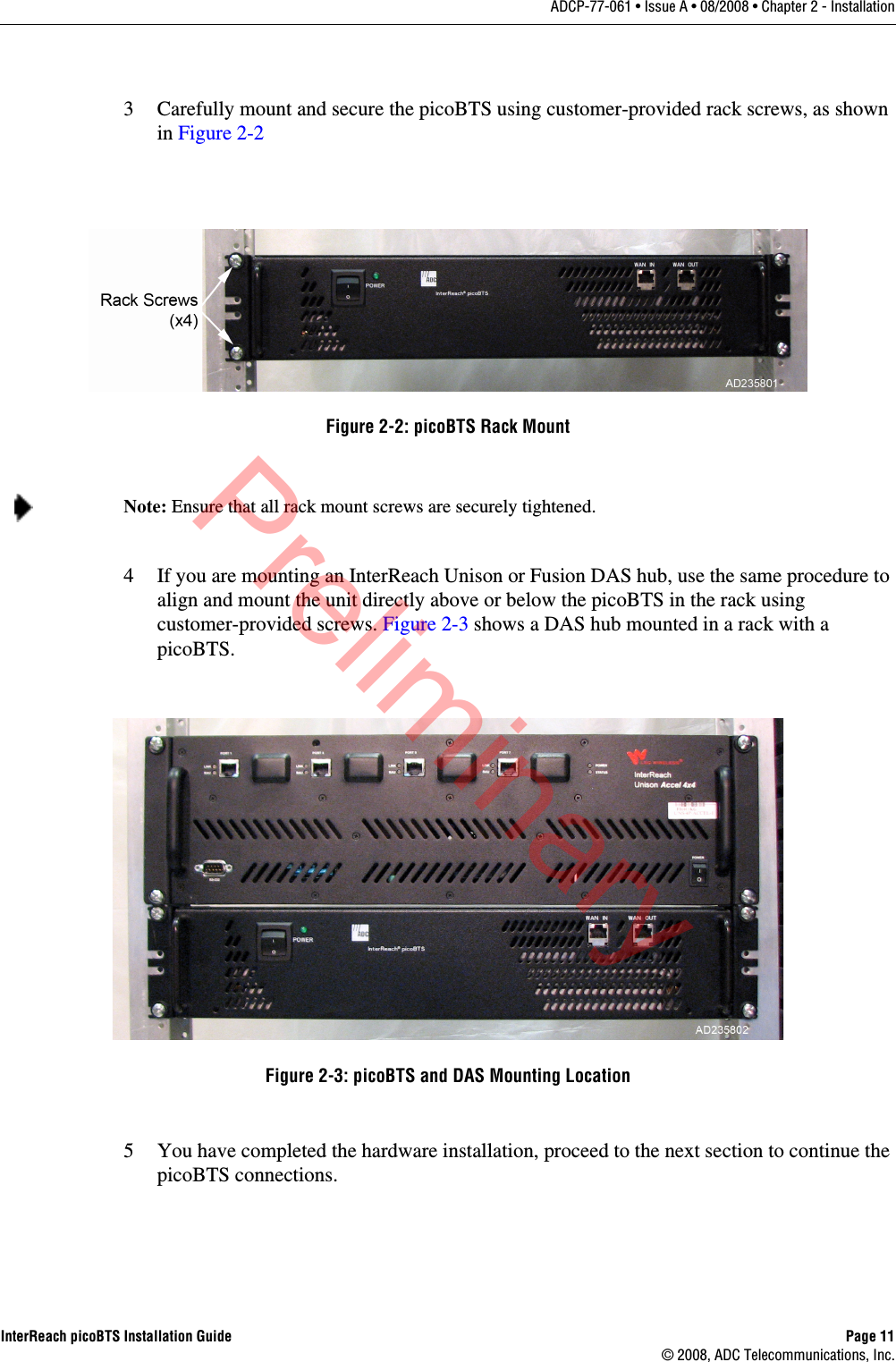
>
ADC Telecommunications
>
IRP0801A User Manual
User manual
Navigation menu
Upload a User Manual
Namespaces
Wiki Guide
HTML
PDF
Info
Views
User Manual
Discussion / Help
Navigation


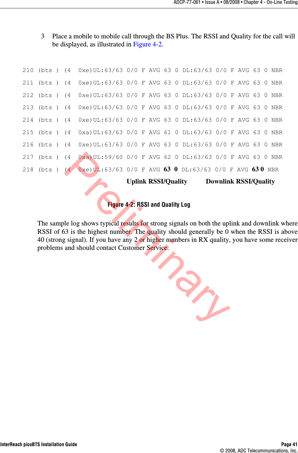
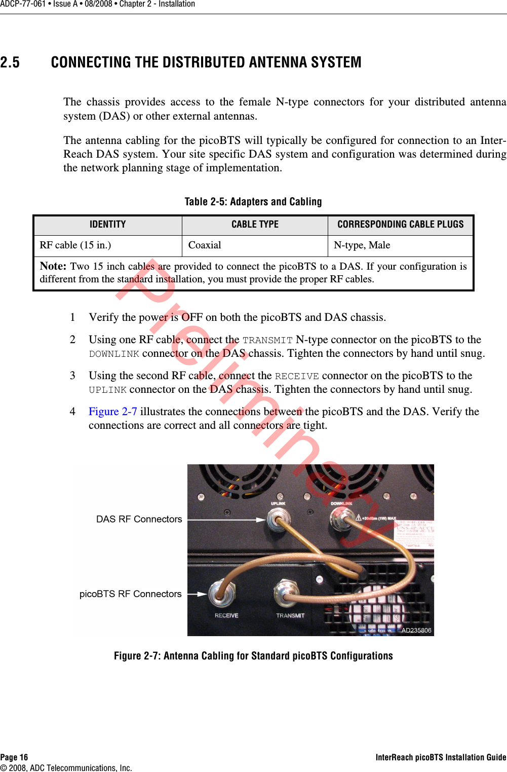
![Page x InterReach picoBTS Installation Guide© 2008, ADC Telecommunications, Inc.ADCP-77-061 • Issue A • 08/2008 • PrefaceADMONISHMENTSImportant safety admonishments are used throughout this manual to warn of possible hazards to persons or equipment. An admonishment identifies a possible hazard and then explains what may happen if the hazard is not avoided. The admonishments — in the form of Dangers, Warnings, and Cautions — must be followed at all times. These warnings are flagged by use of an alert icon (seen below), and are listed in descending order of severity of injury or damage and likelihood of occurrence. CONVENTIONS USED IN THIS MANUALThe following type and style conventions are used in this manual:DANGER: Danger is used to indicate the presence of a hazard that will cause severe personal injury, death, or substantial property damage if the hazard is not avoided.WARNING: Warning is used to indicate the presence of a hazard that can cause severe personal injury, death, or substantial property damage if the hazard is not avoided.Caution: Caution is used to indicate the presence of a hazard that will or can cause minor personal injury or property damage if the hazard is not avoided.Conventions Used in This Manual CONVENTION MEANINGBody Text Used for regular body textBold Indicates a menu or button choiceCommand Indicates computer generated text and promptsUser Input Indicates user input<hostname> In command syntax, indicates user-specified command line parameters<variable> In body text, indicates user-specified command line parameters[BRACKETS] Indicates a key on the keyboard or instrumentNote: Provides relevant additional informationPreliminary](https://usermanual.wiki/ADC-Telecommunications/IRP0801A/User-Guide-1099129-Page-12.png)


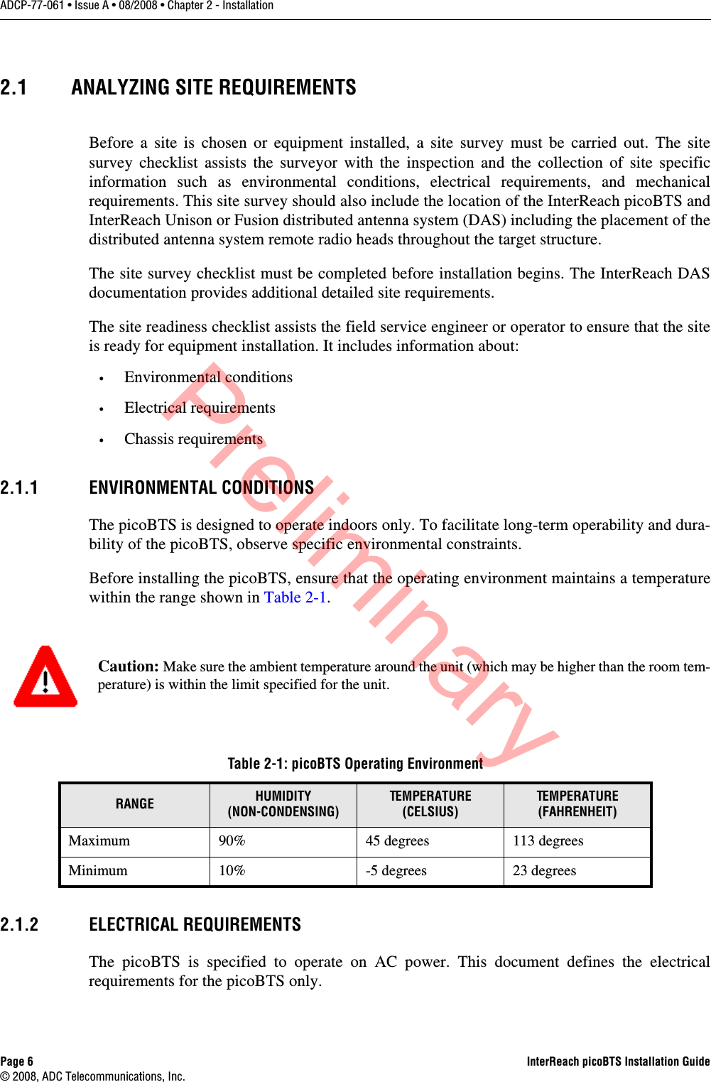


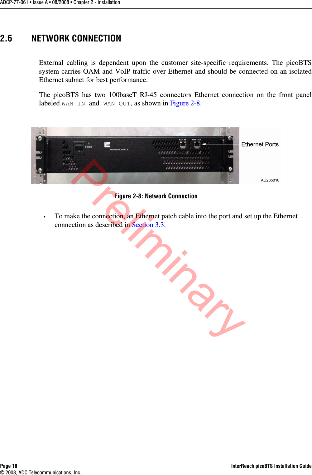


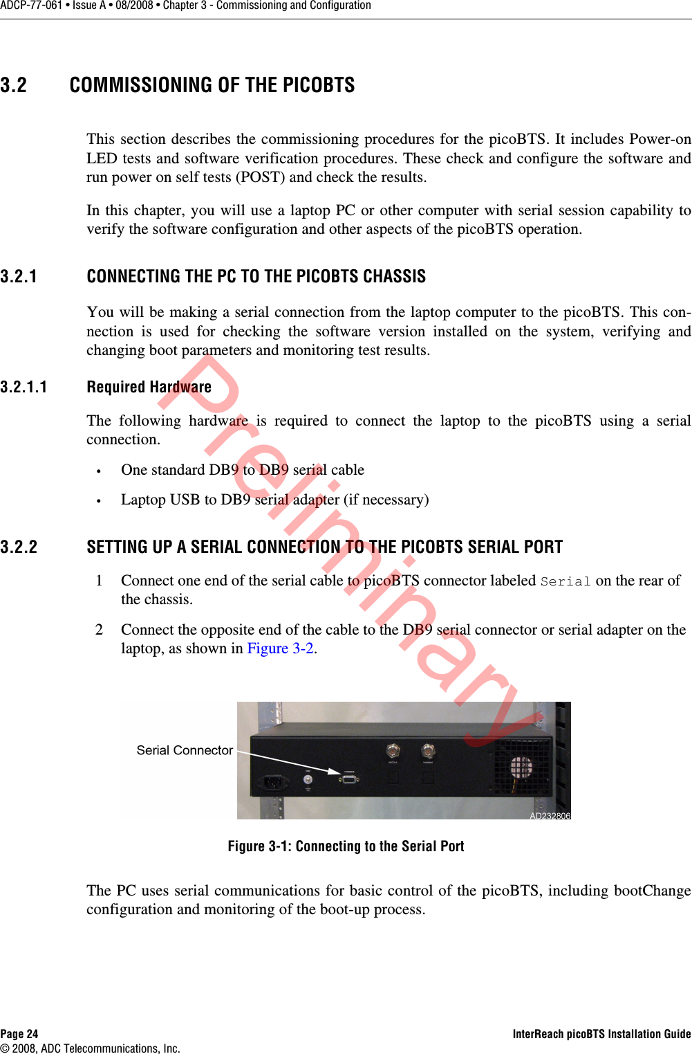
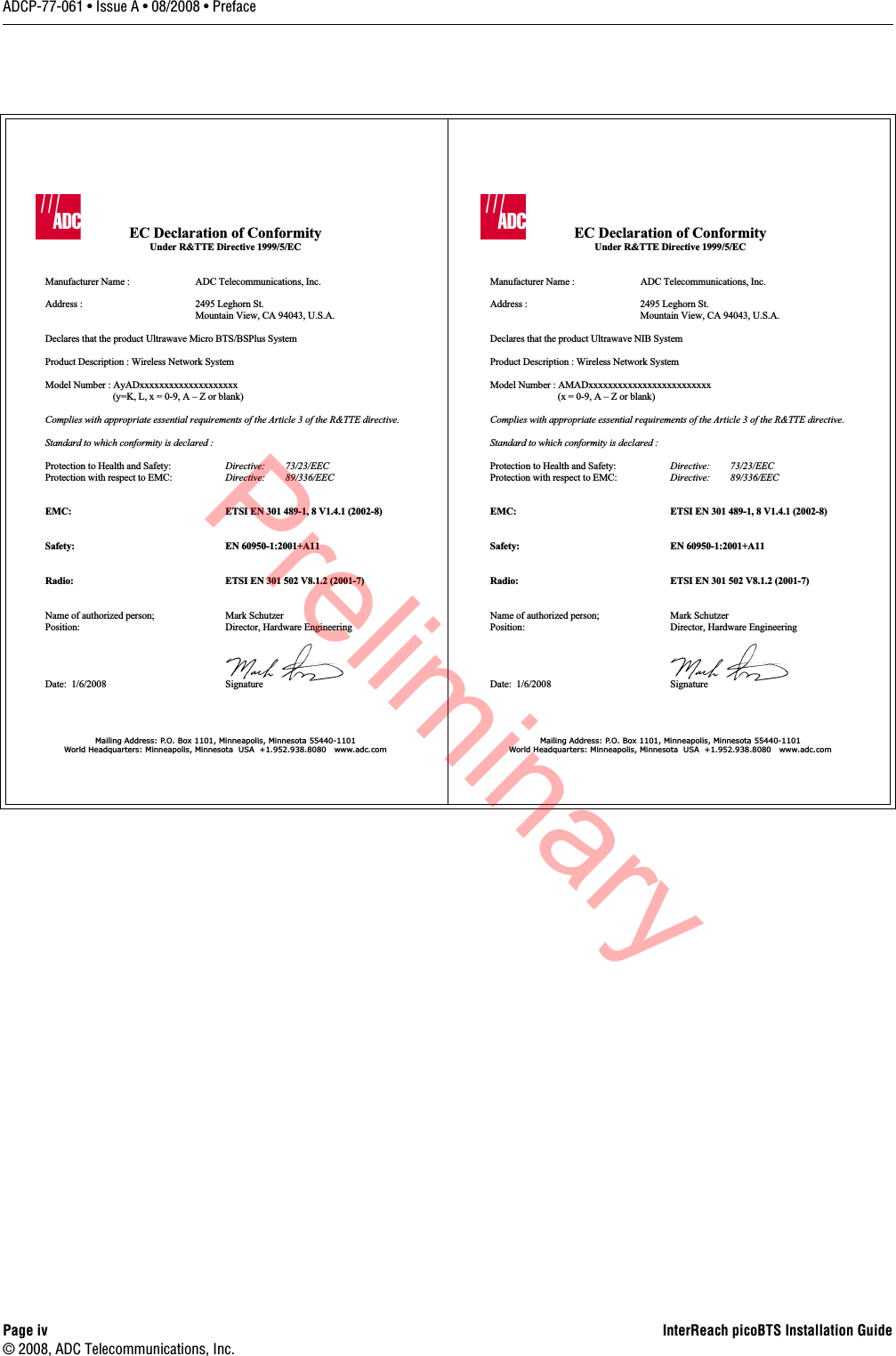
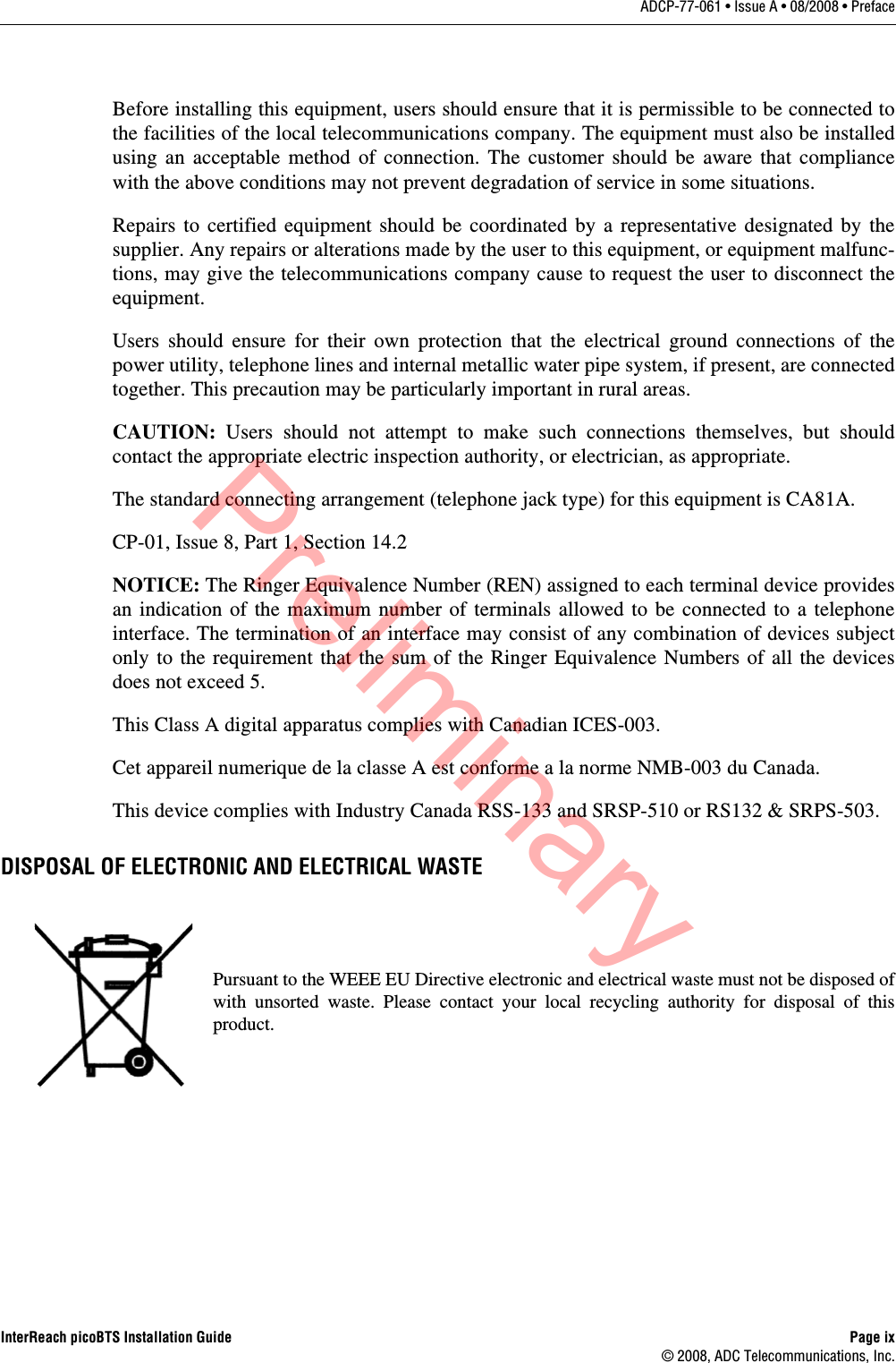
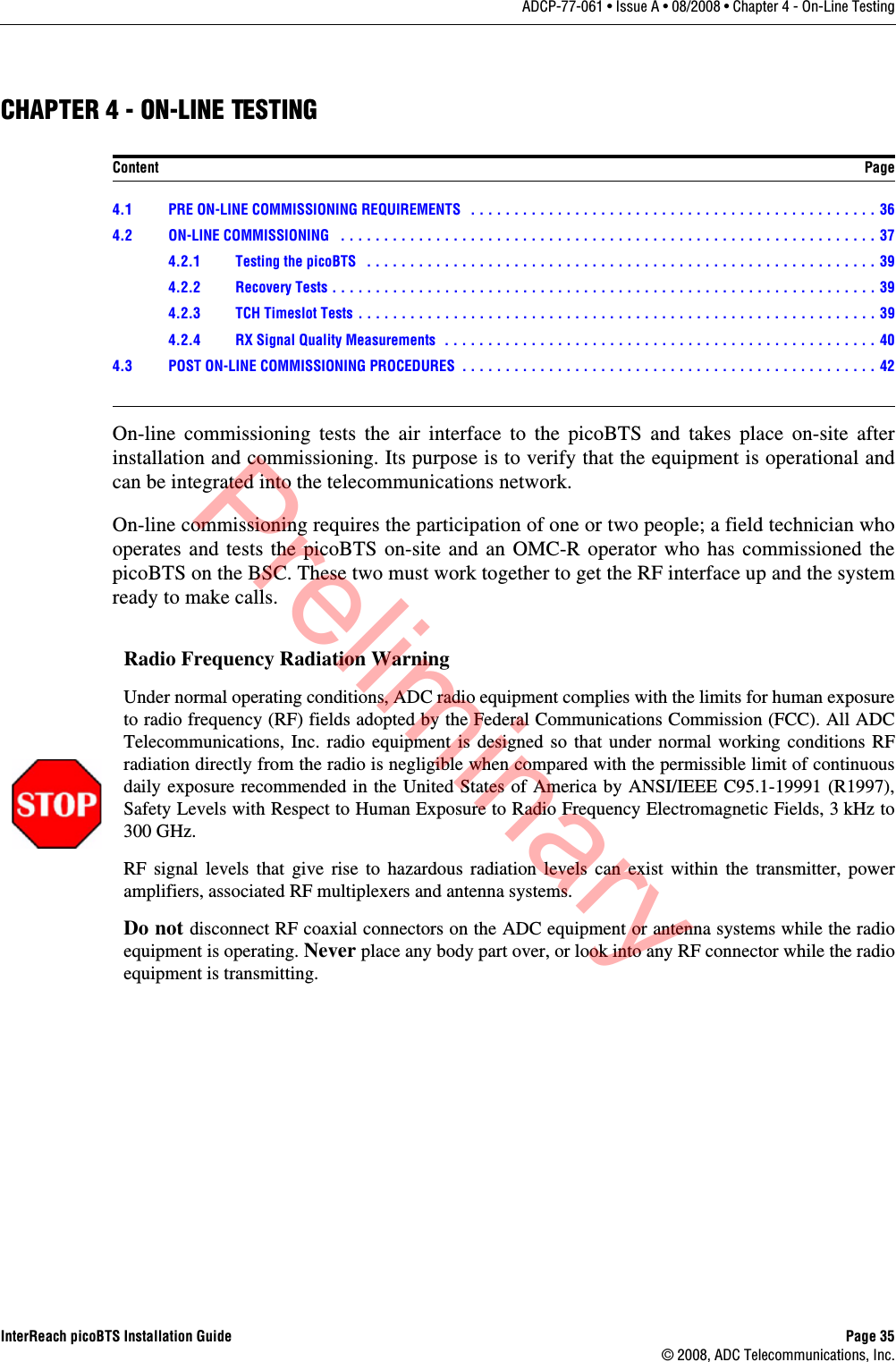
![InterReach picoBTS Installation Guide Page 27© 2008, ADC Telecommunications, Inc.ADCP-77-061 • Issue A • 08/2008 • Chapter 3 - Commissioning and Configuration5 You can monitor the status of the boot process using the serial session opened in Section 3.4.Once the LEDs on the processor cards have reached their final online status, press the [ENTER] key in the HyperTerminal window. The prompt now changes to the following:HD:iwbox->Preliminary](https://usermanual.wiki/ADC-Telecommunications/IRP0801A/User-Guide-1099129-Page-39.png)
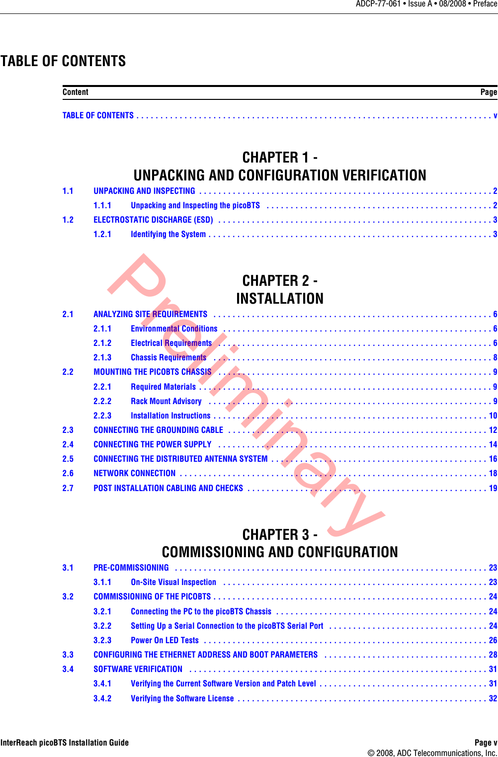
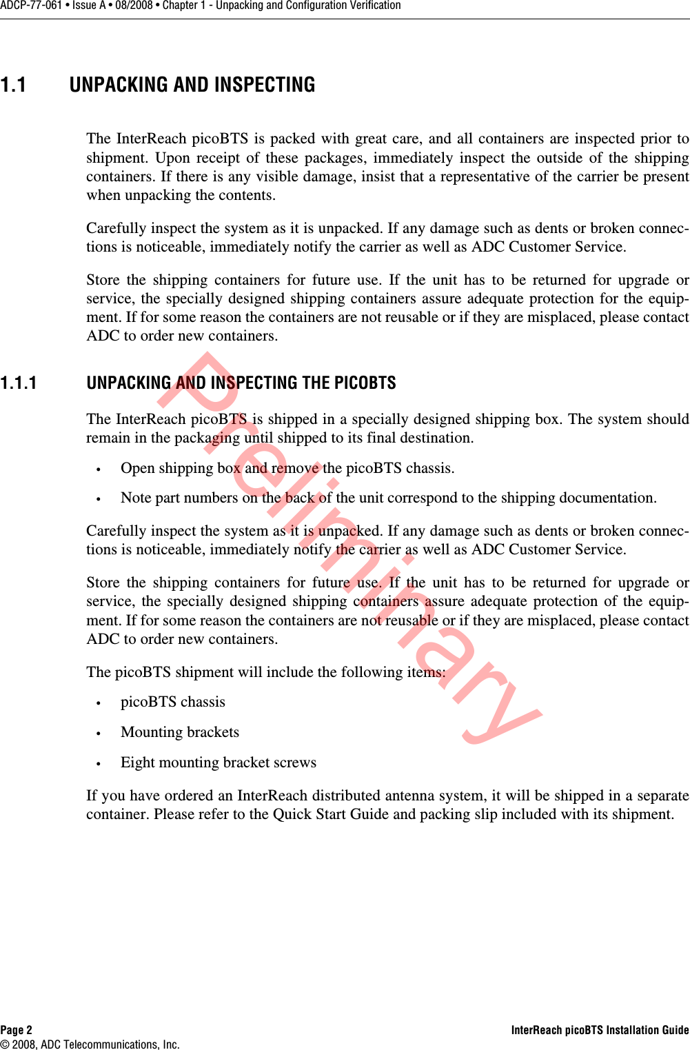
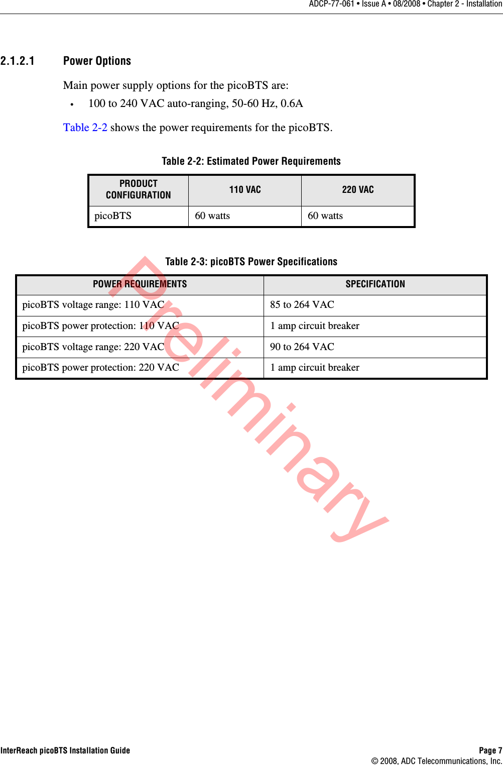
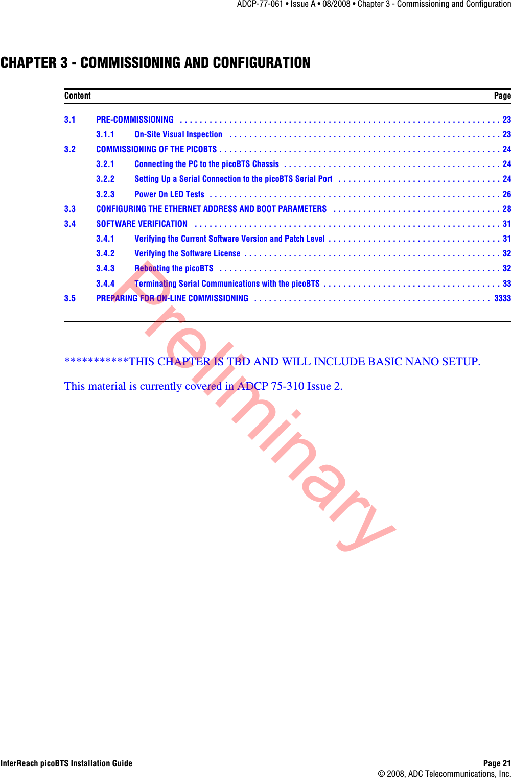
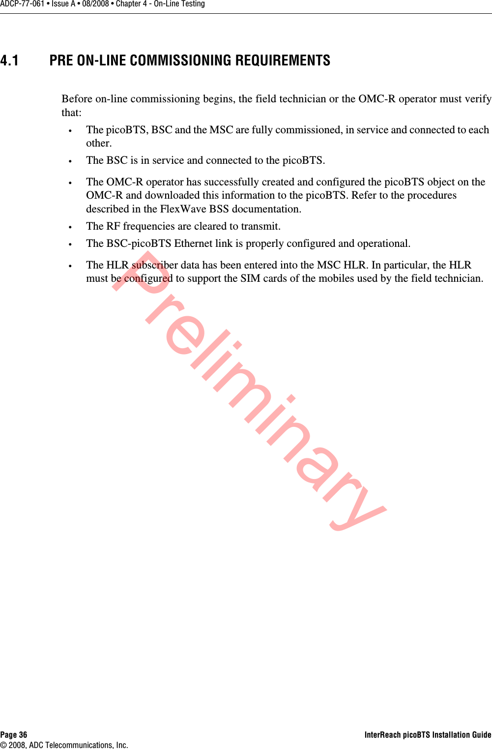
![Page 28 InterReach picoBTS Installation Guide© 2008, ADC Telecommunications, Inc.ADCP-77-061 • Issue A • 08/2008 • Chapter 3 - Commissioning and Configuration3.3 CONFIGURING THE ETHERNET ADDRESS AND BOOT PARAMETERSIn this section, you configure the boot parameters to modify the IP address of the system. After changing the boot parameters, the chassis must be reset before the changes take effect.1 If not already done, establish serial communications with the picoBTS as described in Section 3.2.2.2 Once the picoBTS boots normally, press the [ENTER] key to show the prompt:HD:iwbox->3 Display the boot parameters, by typing:bootChange [ENTER]4 The boot parameters display individually after pressing the [ENTER] key. Each param-eter can be modified by simply entering the new values after the existing value is displayed and pressing the [ENTER] key. You cannot use the backspace or delete keys in this window. Edit the parameter values using the following commands:Figure 3-4 shows the default bootChange parameters for the system. Table 3-2: Changing Boot ParametersCOMMAND ACTION[ENTER] Accepts the current parameter value and proceeds to the next parameter.. [ENTER] Erases the current parameter value and proceeds to the next parameter.- [ENTER] Returns to the previous parameter.[CTRL][d] Aborts all changes and reverts to the current values.Preliminary](https://usermanual.wiki/ADC-Telecommunications/IRP0801A/User-Guide-1099129-Page-40.png)
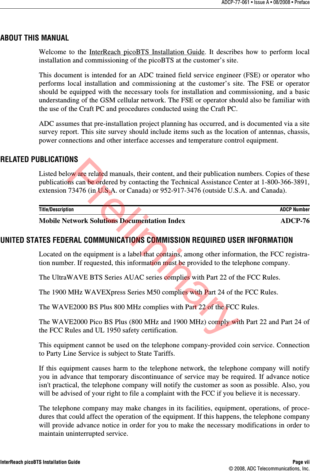
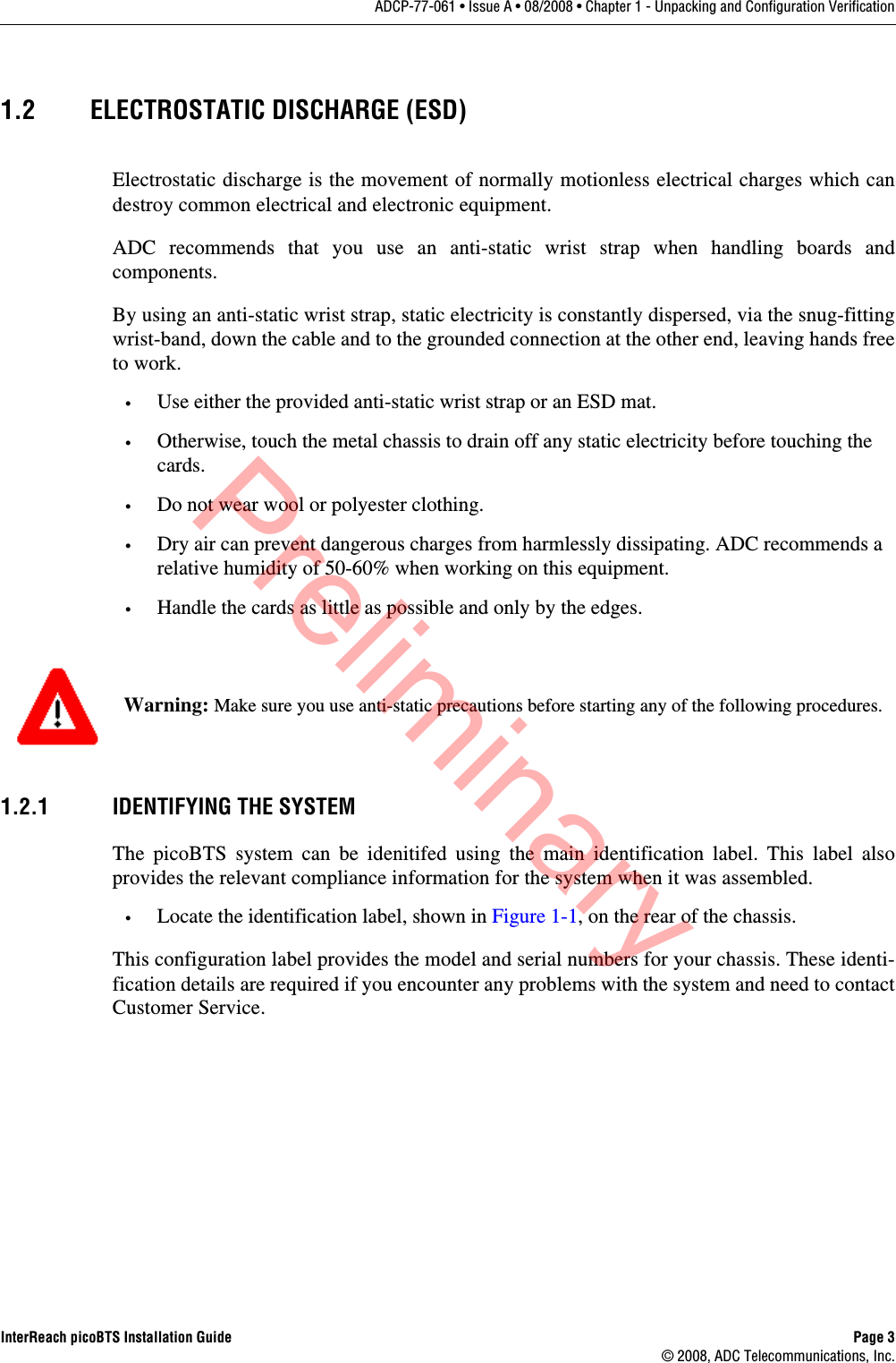
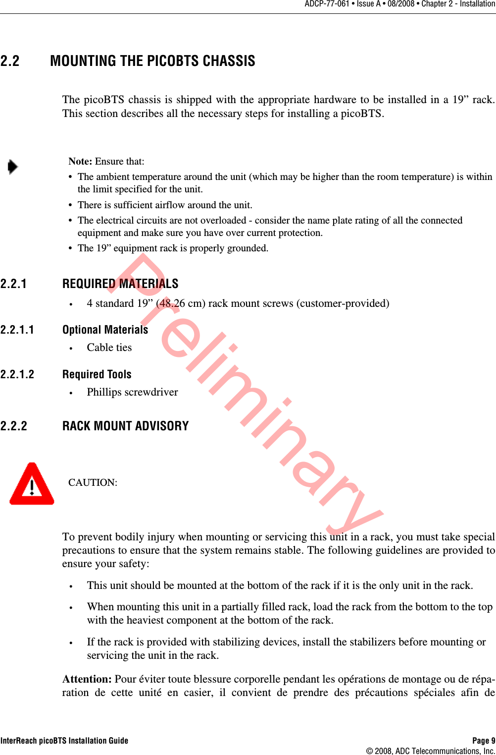
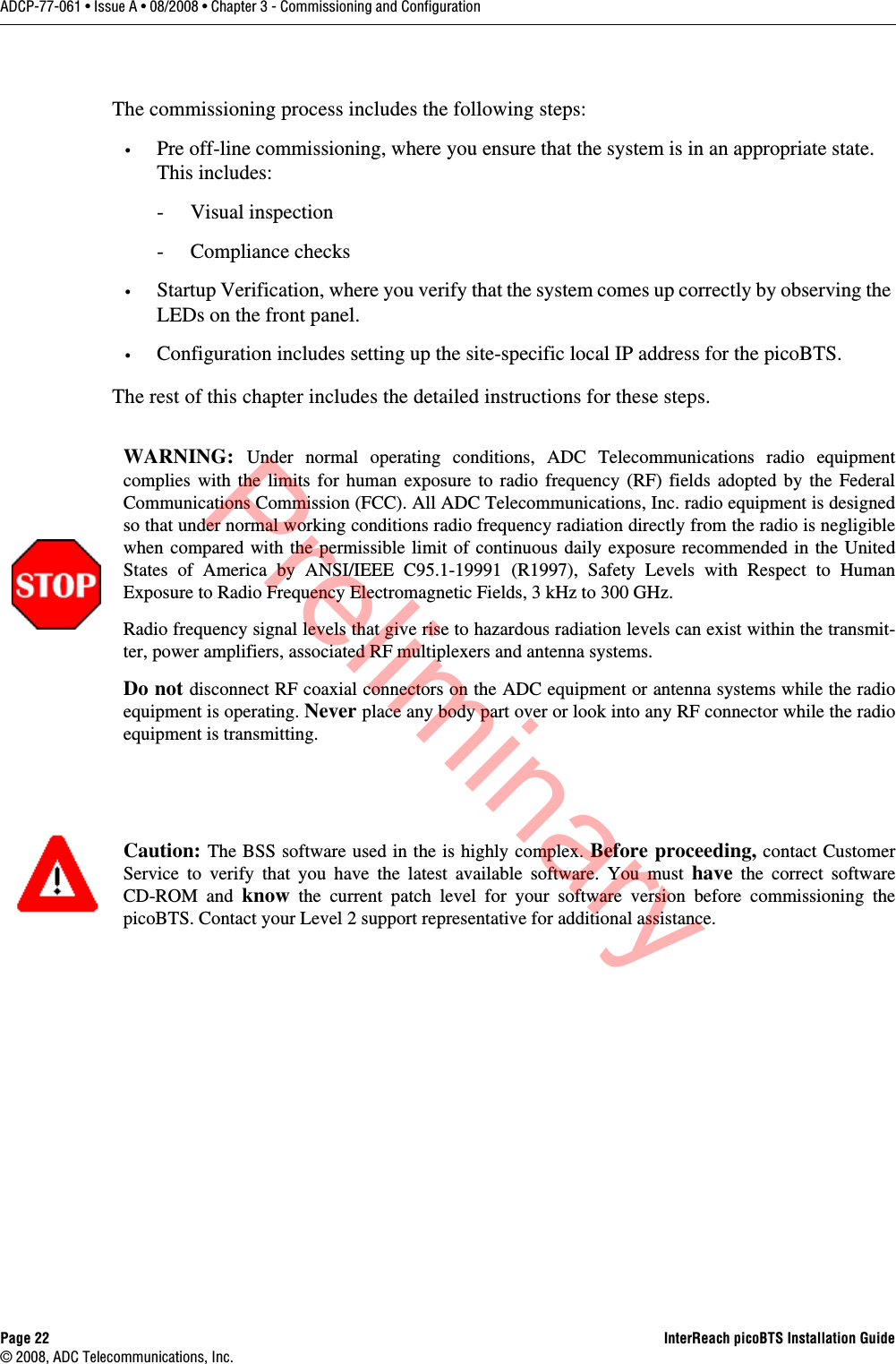
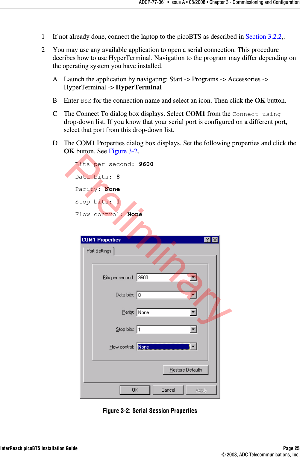
![InterReach picoBTS Installation Guide Page 29© 2008, ADC Telecommunications, Inc.ADCP-77-061 • Issue A • 08/2008 • Chapter 3 - Commissioning and ConfigurationIt is necessary to change the default picoBTS Ethernet address to match your site-specific network configuration. Use the following steps to modify the IP address and target name of the picoBTS.5 Type the bootChange command to edit the boot parameters. The parameters will be displayed one line at a time.bootChange [ENTER]'.' = clear field; '-' = go to previous field; ^D = quit boot device : ata.0 processor number : 0 host name : file name : hd0:/vxWorks inet on ethernet (e) : 172.16.80.42:fffff000 inet on backplane (b): host inet (h) : gateway inet (g) : user (u) : target ftp password (pw) (blank = use rsh): flags (f) : 0x0 target name (tn) : iwbox startup script (s) : /hd0/iwvstart other (o) : motfcc value = 0 = 0x0 HD:iwbox-> _Figure 3-4: Default Boot Parameters'.' = clear field; '-' = go to previous field; ^D = quit boot device : ata.0 processor number : 0 host name : file name : hd0:/vxWorks inet on ethernet (e) : XXX.XXX.XXX.XXX:fffff000 inet on backplane (b): host inet (h) : gateway inet (g) : YYY.YYY.YYY.YYY user (u) : ftp password (pw) (blank = use rsh): flags (f) : 0x0 target name (tn) : TARGETNAME startup script (s) : /hd0/iwvstart other (o) : motfcc value = 0 = 0x0 HD:iwbox-> _Figure 3-5: Boot Parameters Requiring ChangesPreliminary](https://usermanual.wiki/ADC-Telecommunications/IRP0801A/User-Guide-1099129-Page-41.png)
![Page 30 InterReach picoBTS Installation Guide© 2008, ADC Telecommunications, Inc.ADCP-77-061 • Issue A • 08/2008 • Chapter 3 - Commissioning and Configuration6Figure 3-5 shows the IP address parameters which must be modified to add your picoBTS to your Ethernet network.-XXX.XXX.XXX.XXX is the IP address. Replace it with the site-specific Ethernet IP address for your network. The IP address is followed by ‘:fffff000’ which is the subnet mask as a hexadecimal value. To modify the subnet mask of the processor card, determine the proper hexadecimal value and enter following the colon. For example to use a subnet of 255.255.255.0, you would follow the IP address with ‘:ffffff00’. The value displayed in the example ‘:fffff000’ is equal to 255.255.240.0.-YYY.YYY.YYY.YYY is the gateway router IP address. Enter the IP address of the gateway router.- TARGET NAME sets the IP name. The default is “iwbox”. The TARGET NAME parameter sets the IP name. The default is “iwbox”. You should enter a different name for each system. 7 Ensure that all other boot parameters are configured exactly as shown in the previous figures.8 If you have changed anything, for the new parameters to take effect, reboot the chassis by pressing the key combination [CTRL][x]. If you do not receive a prompt after reboot, press [ENTER] to display the HD:iwbox-> prompt.9 Connect an Ethernet RJ-45 patch cable to the WAN port on the front of hte chassis.10 Notify the OMC operator that the picoBTS is connected to the Ethernet, and give the OMC operator the IP address and IP Name.Note: Use the IP name and IP address you received from your network administrator.Caution: You should ONLY change the inet on ethernet, target name and gateway inet parameters. All other parameters should NOT be modified.Caution: The OMC operator MUST have the correct picoBTS IP address, or the OMC will not be able to communicate with the BS Plus.Preliminary](https://usermanual.wiki/ADC-Telecommunications/IRP0801A/User-Guide-1099129-Page-42.png)
![InterReach picoBTS Installation Guide Page 31© 2008, ADC Telecommunications, Inc.ADCP-77-061 • Issue A • 08/2008 • Chapter 3 - Commissioning and Configuration3.4 SOFTWARE VERIFICATIONYou should use the following commissioning procedures to verify the software installed on the picoBTS.3.4.1 VERIFYING THE CURRENT SOFTWARE VERSION AND PATCH LEVEL1 If not already done, establish serial communications with the picoBTS as described in Section 3.2.2.2After the HD:iwbox-> prompt appears, verify the current software version and patch level by typing:iwversion [ENTER]The following software information will be displayed:BSC code version: iw07_05.ZZZRelease number: 7.5ABIS version: 1.1Packages Installed: Encryption: A5/1Patches Installed: patch<#> <file directory> <patch size> <iw07_05.ZZZ>The current software version is displayed, represented above by the parameter iw07_05.ZZZ.This number should correspond to the software version detailed in the release notes included with the CD-ROM. Keep this number for your records.3 Verify under Patches Installed: that the most current patch is installed, if appli-cable. Refer to the GSM Craft PC User Guide for procedures to install required patches. If you are unsure if you require software patches, contact your Level 2 support representa-tive for additional assistance.Note: The following section describes procedures performed using the Craft PC. For more information pertaining to the use of the Craft PC, please refer to the GSM Craft PC User Guide.Note: If the displayed software version number does not coincide with the software version being run on the network for which this picoBTS is going to be used, contact Customer Service for instructions on how to install a different software version.Preliminary](https://usermanual.wiki/ADC-Telecommunications/IRP0801A/User-Guide-1099129-Page-43.png)
![Page 32 InterReach picoBTS Installation Guide© 2008, ADC Telecommunications, Inc.ADCP-77-061 • Issue A • 08/2008 • Chapter 3 - Commissioning and Configuration3.4.2 VERIFYING THE SOFTWARE LICENSEIn this section you will complete the following procedures:•Backup the software license files from the processor card to the PC or OMC.•Verify the software license files are compatible with the system.1 Verify the serial cable is connected to the chassis and you have an open serial session as detailed in Section 3.2.2.2 Verify the license file using the following command:printLicenseKeyThe following output is a sample of properly configured license file:License Keys :printLicenseKeyGENERAL : VALIDGPRS : VALIDFREQHOP : VALIDXTNDCELL : VALIDSECTOR : VALIDTRX_84 : VALIDPDCH_60 : VALIDvalue = 1 = 0x1HD:iwbox-> Done.The licenses will vary depending based on your sales order and your network configuration. Your license will not have all of the the entries listed above and may display an error message similar to the following:1219117434.733 (tShell) VerifyKey: key not found 4This is normal, however if your license does not have any VALID entries. The file may be corrupt or not properly installed, contact Customer Service. 3.4.3 REBOOTING THE PICOBTS•Using the serial session window, reboot the picoBTS by typing:reboot [ENTER]The entire chassis will now reboot. Preliminary](https://usermanual.wiki/ADC-Telecommunications/IRP0801A/User-Guide-1099129-Page-44.png)

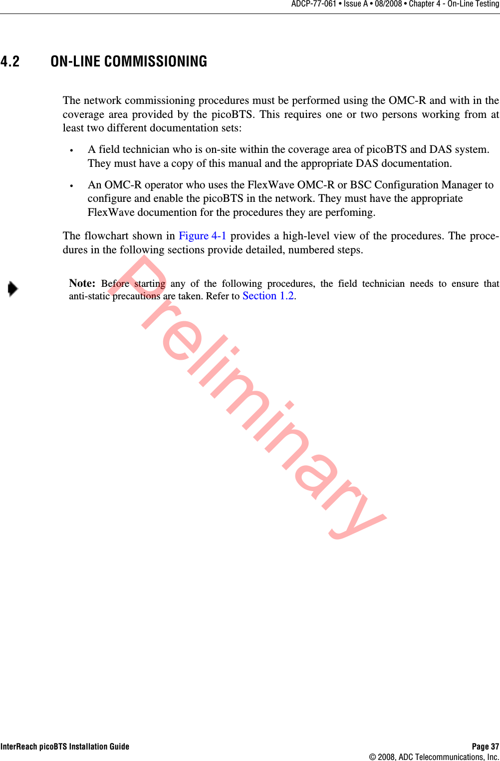
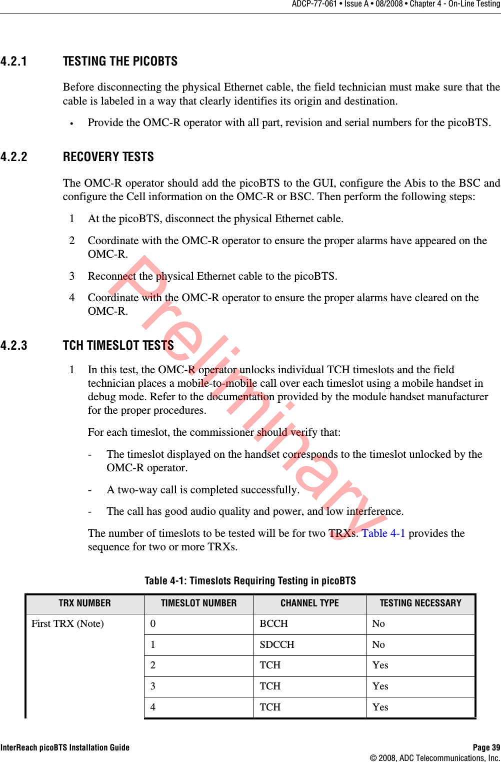
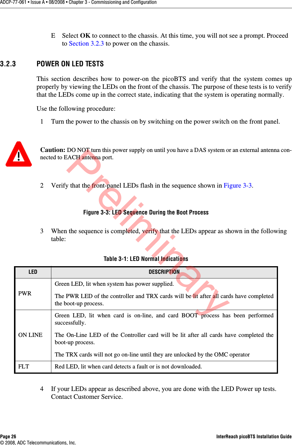
![Page 40 InterReach picoBTS Installation Guide© 2008, ADC Telecommunications, Inc.ADCP-77-061 • Issue A • 08/2008 • Chapter 4 - On-Line Testing4.2.4 RX SIGNAL QUALITY MEASUREMENTSThe objectives of this test are to verify the performance of the Receive path of the picoBTSand the operation of the RX module in the TRX. Before these tests can take place, the picoBTSmust be returned to its original “on air” working state with call processing possible.1 From an Xterm window on the OMC-R, telnet to the picoBTS to be tested, or alternatively connect directly using a serial session to the picoBTS with the laptop PC.THIS SECTION FROM HERE IS TOO BE DETERMINED.2 From the picoBTS prompt type the following to activate the RX RSSI and quality data logging:HD:iwbox-> log_none [ENTER] HD:iwbox-> ho_log_on_bts [ENTER]5TCHYes6TCHYes7TCHYesSecond TRX (Note) 0 TCH Yes1TCHYes2TCHYes3TCHYes4TCHYes5TCHYes6TCHYes7TCHYesNote: The BCCH can be assigned to any TRX within the picoBTS. The label “First TRX” applies to the TRX to which is assigned the BCCH. All TCH timeslots on the secondTRX must be tested.Table 4-1: Timeslots Requiring Testing in picoBTS, continuedTRX NUMBER TIMESLOT NUMBER CHANNEL TYPE TESTING NECESSARYPreliminary](https://usermanual.wiki/ADC-Telecommunications/IRP0801A/User-Guide-1099129-Page-52.png)