ADC Telecommunications IRP1901A InterReach® picoBTS 1900 MHz User Manual
ADC Telecommunications Inc InterReach® picoBTS 1900 MHz
User manual
Mobile Network Solutions
InterReach™ picoBTS
Installation and Commissioning Guide
D-620091-0-20 Ver. A
AD235808
ADCP-77-061 • Issue A • 08/2008
Preliminary
Preliminary

Mobile Network Solutions
UltraWAVE picoBTS
Installation and Commissioning Guide
ADCP-77-061 • Issue A • 08/2008
D-620091-0-20 Ver. A
Preliminary

ADCP-77-061 • Issue A • 08/2008 • Preface
Page ii InterReach picoBTS Installation Guide
© 2008, ADC Telecommunications, Inc.
COPYRIGHT
© 2008, ADC Telecommunications, Inc.
All Rights Reserved
REVISION HISTORY
LIST OF CHANGES
The technical changes incorporated into this issue are listed below.
TRADEMARK INFORMATION
ADC is a registered trademark and InterReach, InterReach Unison, InterReach Fusion, WAVEXchange, FlexWave are registered
trademarks and trademarks of ADC Telecommunications, Inc. or LGC Wireless, Inc. a wholly owned subsidiary of ADC. All other
products, company names, service marks, and trademarks mentioned in this document or website are used for identification
purposes only and may be owned by other companies.
DISCLAIMER OF LIABILITY
Contents herein are current as of the date of publication. ADC reserves the right to change the contents without prior notice. In no
event shall ADC be liable for any damages resulting from loss of data, loss of use, or loss of profits and ADC further
disclaims any and all liability for indirect, incidental, special, consequential or other similar damages. This disclaimer of
liability applies to all products, publications and services during and after the warranty period.
This publication may be verified at any time by contacting ADC’s Technical Assistance Center at 1-800-366-3891, extension 73476
(in U.S.A. or Canada) or 952-917-3476 (outside U.S.A. and Canada), or by e-mail to wireless.tac@adc.com.
ISSUE DATE REASON FOR CHANGE
A 08/2008 Original
PAGE IDENTIFIER DESCRIPTION OF CHANGE
All New publication
ADC Telecommunications, Inc.
P.O. Box 1101, Minneapolis, Minnesota 55440-1101
In U.S.A. and Canada: 1-800-366-3891
Outside U.S.A. and Canada: (952) 938-8080
Fax: (952) 917-1717
Preliminary

ADCP-77-061 • Issue A • 08/2008 • Preface
InterReach picoBTS Installation Guide Page iii
© 2008, ADC Telecommunications, Inc.
DECLARATIONS OF CONFORMITY
Mailing Address: P.O. Box 1101, Minneapolis, Minnesota 55440-1101
World Headquarters: Minneapolis, Minnesota USA +1.952.938.8080 www.adc.com
EC Declaration of Conformity
Under R&TTE Directive 1999/5/EC
Manufacturer Name : ADC Telecommunications, Inc.
Address : 2495 Leghorn St.
Mountain View, CA 94043, U.S.A.
Declares that the product Ultrawave Base Station Controller System
Product Description : Base Station Controller
Model Number : ASABxxxxxxxxxxxxxxxxxxxxxxxxx
(x = 0-9, A – Z or blank)
Complies with appropriate essential requirements of the Article 3 of the R&TTE directive.
Standard to which conformity is declared :
Protection to Health and Safety: Directive: 73/23/EEC
Protection with respect to EMC: Directive: 89/336/EEC
EMC: ETSI EN 300 386 V1.2.1 (2000-03)
Safety: EN 60950-1:2001+A11
Name of authorized person; Mark Schutzer
Position: Director, Hardware Engineering
Date: 1/6/2008 Signature
Mailing Address: P.O. Box 1101, Minneapolis, Minnesota 55440-1101
World Headquarters: Minneapolis, Minnesota USA +1.952.938.8080 www.adc.com
EC Declaration of Conformity
Under R&TTE Directive 1999/5/EC
Manufacturer Name : ADC Telecommunications, Inc.
Address : 2495 Leghorn St.
Mountain View, CA 94043, U.S.A.
Declares that the product Ultrawave BTS/BSPlus 850/900/1800MHz System
Product Description : GSM Base Transceiver Station
Model Number : AVADxxxxxxxxxxxxxxxxxxxx
(x = 0-9, A – Z or blank)
Complies with appropriate essential requirements of the Article 3 of the R&TTE directive.
Standard to which conformity is declared :
Protection to Health and Safety: Directive: 73/23/EEC
Protection with respect to EMC: Directive: 89/336/EEC
EMC: ETSI EN 301 489-1, 8 V1.4.1 (2002-8)
Safety: EN 60950-1:2001+A11
Radio: ETSI EN 301 502 V8.1.2 (2001-7)
Name of authorized person; Mark Schutzer
Position: Director, Hardware Engineering
Date: 1/6/2008 Signature
Preliminary

ADCP-77-061 • Issue A • 08/2008 • Preface
Page iv InterReach picoBTS Installation Guide
© 2008, ADC Telecommunications, Inc.
Mailing Address: P.O. Box 1101, Minneapolis, Minnesota 55440-1101
World Headquarters: Minneapolis, Minnesota USA +1.952.938.8080 www.adc.com
EC Declaration of Conformity
Under R&TTE Directive 1999/5/EC
Manufacturer Name : ADC Telecommunications, Inc.
Address : 2495 Leghorn St.
Mountain View, CA 94043, U.S.A.
Declares that the product Ultrawave Micro BTS/BSPlus System
Product Description : Wireless Network System
Model Number : AyADxxxxxxxxxxxxxxxxxxxx
(y=K, L, x = 0-9, A – Z or blank)
Complies with appropriate essential requirements of the Article 3 of the R&TTE directive.
Standard to which conformity is declared :
Protection to Health and Safety: Directive: 73/23/EEC
Protection with respect to EMC: Directive: 89/336/EEC
EMC: ETSI EN 301 489-1, 8 V1.4.1 (2002-8)
Safety: EN 60950-1:2001+A11
Radio: ETSI EN 301 502 V8.1.2 (2001-7)
Name of authorized person; Mark Schutzer
Position: Director, Hardware Engineering
Date: 1/6/2008 Signature
Mailing Address: P.O. Box 1101, Minneapolis, Minnesota 55440-1101
World Headquarters: Minneapolis, Minnesota USA +1.952.938.8080 www.adc.com
EC Declaration of Conformity
Under R&TTE Directive 1999/5/EC
Manufacturer Name : ADC Telecommunications, Inc.
Address : 2495 Leghorn St.
Mountain View, CA 94043, U.S.A.
Declares that the product Ultrawave NIB System
Product Description : Wireless Network System
Model Number : AMADxxxxxxxxxxxxxxxxxxxxxxxxx
(x = 0-9, A – Z or blank)
Complies with appropriate essential requirements of the Article 3 of the R&TTE directive.
Standard to which conformity is declared :
Protection to Health and Safety: Directive: 73/23/EEC
Protection with respect to EMC: Directive: 89/336/EEC
EMC: ETSI EN 301 489-1, 8 V1.4.1 (2002-8)
Safety: EN 60950-1:2001+A11
Radio: ETSI EN 301 502 V8.1.2 (2001-7)
Name of authorized person; Mark Schutzer
Position: Director, Hardware Engineering
Date: 1/6/2008 Signature
Preliminary

InterReach picoBTS Installation Guide Page v
© 2008, ADC Telecommunications, Inc.
ADCP-77-061 • Issue A • 08/2008 • Preface
TABLE OF CONTENTS
TABLE OF CONTENTS . . . . . . . . . . . . . . . . . . . . . . . . . . . . . . . . . . . . . . . . . . . . . . . . . . . . . . . . . . . . . . . . . . . . . . . . . . v
CHAPTER 1 -
UNPACKING AND CONFIGURATION VERIFICATION
1.1 UNPACKING AND INSPECTING . . . . . . . . . . . . . . . . . . . . . . . . . . . . . . . . . . . . . . . . . . . . . . . . . . . . . . . . . . . . . 2
1.1.1 Unpacking and Inspecting the picoBTS . . . . . . . . . . . . . . . . . . . . . . . . . . . . . . . . . . . . . . . . . . . . . . . 2
1.2 ELECTROSTATIC DISCHARGE (ESD) . . . . . . . . . . . . . . . . . . . . . . . . . . . . . . . . . . . . . . . . . . . . . . . . . . . . . . . . . 3
1.2.1 Identifying the System . . . . . . . . . . . . . . . . . . . . . . . . . . . . . . . . . . . . . . . . . . . . . . . . . . . . . . . . . . . 3
CHAPTER 2 -
INSTALLATION
2.1 ANALYZING SITE REQUIREMENTS . . . . . . . . . . . . . . . . . . . . . . . . . . . . . . . . . . . . . . . . . . . . . . . . . . . . . . . . . . 6
2.1.1 Environmental Conditions . . . . . . . . . . . . . . . . . . . . . . . . . . . . . . . . . . . . . . . . . . . . . . . . . . . . . . . . 6
2.1.2 Electrical Requirements . . . . . . . . . . . . . . . . . . . . . . . . . . . . . . . . . . . . . . . . . . . . . . . . . . . . . . . . . 6
2.1.3 Chassis Requirements . . . . . . . . . . . . . . . . . . . . . . . . . . . . . . . . . . . . . . . . . . . . . . . . . . . . . . . . . . 8
2.2 MOUNTING THE PICOBTS CHASSIS . . . . . . . . . . . . . . . . . . . . . . . . . . . . . . . . . . . . . . . . . . . . . . . . . . . . . . . . . 9
2.2.1 Required Materials . . . . . . . . . . . . . . . . . . . . . . . . . . . . . . . . . . . . . . . . . . . . . . . . . . . . . . . . . . . . . 9
2.2.2 Rack Mount Advisory . . . . . . . . . . . . . . . . . . . . . . . . . . . . . . . . . . . . . . . . . . . . . . . . . . . . . . . . . . . 9
2.2.3 Installation Instructions . . . . . . . . . . . . . . . . . . . . . . . . . . . . . . . . . . . . . . . . . . . . . . . . . . . . . . . . . 10
2.3 CONNECTING THE GROUNDING CABLE . . . . . . . . . . . . . . . . . . . . . . . . . . . . . . . . . . . . . . . . . . . . . . . . . . . . . . 12
2.4 CONNECTING THE POWER SUPPLY . . . . . . . . . . . . . . . . . . . . . . . . . . . . . . . . . . . . . . . . . . . . . . . . . . . . . . . . 14
2.5 CONNECTING THE DISTRIBUTED ANTENNA SYSTEM . . . . . . . . . . . . . . . . . . . . . . . . . . . . . . . . . . . . . . . . . . . . . 16
2.6 NETWORK CONNECTION . . . . . . . . . . . . . . . . . . . . . . . . . . . . . . . . . . . . . . . . . . . . . . . . . . . . . . . . . . . . . . . . 18
2.7 POST INSTALLATION CABLING AND CHECKS . . . . . . . . . . . . . . . . . . . . . . . . . . . . . . . . . . . . . . . . . . . . . . . . . . 19
CHAPTER 3 -
COMMISSIONING AND CONFIGURATION
3.1 PRE-COMMISSIONING . . . . . . . . . . . . . . . . . . . . . . . . . . . . . . . . . . . . . . . . . . . . . . . . . . . . . . . . . . . . . . . . . 23
3.1.1 On-Site Visual Inspection . . . . . . . . . . . . . . . . . . . . . . . . . . . . . . . . . . . . . . . . . . . . . . . . . . . . . . . 23
3.2 COMMISSIONING OF THE PICOBTS . . . . . . . . . . . . . . . . . . . . . . . . . . . . . . . . . . . . . . . . . . . . . . . . . . . . . . . . . 24
3.2.1 Connecting the PC to the picoBTS Chassis . . . . . . . . . . . . . . . . . . . . . . . . . . . . . . . . . . . . . . . . . . . . 24
3.2.2 Setting Up a Serial Connection to the picoBTS Serial Port . . . . . . . . . . . . . . . . . . . . . . . . . . . . . . . . . 24
3.2.3 Power On LED Tests . . . . . . . . . . . . . . . . . . . . . . . . . . . . . . . . . . . . . . . . . . . . . . . . . . . . . . . . . . . 26
3.3 CONFIGURING THE ETHERNET ADDRESS AND BOOT PARAMETERS . . . . . . . . . . . . . . . . . . . . . . . . . . . . . . . . . . 28
3.4 SOFTWARE VERIFICATION . . . . . . . . . . . . . . . . . . . . . . . . . . . . . . . . . . . . . . . . . . . . . . . . . . . . . . . . . . . . . . 31
3.4.1 Verifying the Current Software Version and Patch Level . . . . . . . . . . . . . . . . . . . . . . . . . . . . . . . . . . . 31
3.4.2 Verifying the Software License . . . . . . . . . . . . . . . . . . . . . . . . . . . . . . . . . . . . . . . . . . . . . . . . . . . . 32
Content Page
Preliminary

Page vi InterReach picoBTS Installation Guide
© 2008, ADC Telecommunications, Inc.
ADCP-77-061 • Issue A • 08/2008 • Preface
3.4.3 Rebooting the picoBTS . . . . . . . . . . . . . . . . . . . . . . . . . . . . . . . . . . . . . . . . . . . . . . . . . . . . . . . . . . 32
3.4.4 Terminating Serial Communications with the picoBTS . . . . . . . . . . . . . . . . . . . . . . . . . . . . . . . . . . . .33
3.5 PREPARING FOR ON-LINE COMMISSIONING . . . . . . . . . . . . . . . . . . . . . . . . . . . . . . . . . . . . . . . . . . . . . . . . . . 33
CHAPTER 4 -
ON-LINE TESTING
4.1 PRE ON-LINE COMMISSIONING REQUIREMENTS . . . . . . . . . . . . . . . . . . . . . . . . . . . . . . . . . . . . . . . . . . . . . . . 36
4.2 ON-LINE COMMISSIONING . . . . . . . . . . . . . . . . . . . . . . . . . . . . . . . . . . . . . . . . . . . . . . . . . . . . . . . . . . . . . . . 37
4.2.1 Testing the picoBTS . . . . . . . . . . . . . . . . . . . . . . . . . . . . . . . . . . . . . . . . . . . . . . . . . . . . . . . . . . . . 39
4.2.2 Recovery Tests . . . . . . . . . . . . . . . . . . . . . . . . . . . . . . . . . . . . . . . . . . . . . . . . . . . . . . . . . . . . . . . 39
4.2.3 TCH Timeslot Tests . . . . . . . . . . . . . . . . . . . . . . . . . . . . . . . . . . . . . . . . . . . . . . . . . . . . . . . . . . . . 39
4.2.4 RX Signal Quality Measurements . . . . . . . . . . . . . . . . . . . . . . . . . . . . . . . . . . . . . . . . . . . . . . . . . . 40
4.3 POST ON-LINE COMMISSIONING PROCEDURES . . . . . . . . . . . . . . . . . . . . . . . . . . . . . . . . . . . . . . . . . . . . . . . . 42
Preliminary

InterReach picoBTS Installation Guide Page vii
© 2008, ADC Telecommunications, Inc.
ADCP-77-061 • Issue A • 08/2008 • Preface
ABOUT THIS MANUAL
Welcome to the InterReach picoBTS Installation Guide. It describes how to perform local
installation and commissioning of the picoBTS at the customer’s site.
This document is intended for an ADC trained field service engineer (FSE) or operator who
performs local installation and commissioning at the customer’s site. The FSE or operator
should be equipped with the necessary tools for installation and commissioning, and a basic
understanding of the GSM cellular network. The FSE or operator should also be familiar with
the use of the Craft PC and procedures conducted using the Craft PC.
ADC assumes that pre-installation project planning has occurred, and is documented via a site
survey report. This site survey should include items such as the location of antennas, chassis,
power connections and other interface accesses and temperature control equipment.
RELATED PUBLICATIONS
Listed below are related manuals, their content, and their publication numbers. Copies of these
publications can be ordered by contacting the Technical Assistance Center at 1-800-366-3891,
extension 73476 (in U.S.A. or Canada) or 952-917-3476 (outside U.S.A. and Canada).
Mobile Network Solutions Documentation Index ADCP-76
UNITED STATES FEDERAL COMMUNICATIONS COMMISSION REQUIRED USER INFORMATION
Located on the equipment is a label that contains, among other information, the FCC registra-
tion number. If requested, this information must be provided to the telephone company.
The UltraWAVE BTS Series AUAC series complies with Part 22 of the FCC Rules.
The 1900 MHz WAVEXpress Series M50 complies with Part 24 of the FCC Rules.
The WAVE2000 BS Plus 800 MHz complies with Part 22 of the FCC Rules.
The WAVE2000 Pico BS Plus (800 MHz and 1900 MHz) comply with Part 22 and Part 24 of
the FCC Rules and UL 1950 safety certification.
This equipment cannot be used on the telephone company-provided coin service. Connection
to Party Line Service is subject to State Tariffs.
If this equipment causes harm to the telephone network, the telephone company will notify
you in advance that temporary discontinuance of service may be required. If advance notice
isn't practical, the telephone company will notify the customer as soon as possible. Also, you
will be advised of your right to file a complaint with the FCC if you believe it is necessary.
The telephone company may make changes in its facilities, equipment, operations, of proce-
dures that could affect the operation of the equipment. If this happens, the telephone company
will provide advance notice in order for you to make the necessary modifications in order to
maintain uninterrupted service.
Title/Description ADCP Number
Preliminary

Page viii InterReach picoBTS Installation Guide
© 2008, ADC Telecommunications, Inc.
ADCP-77-061 • Issue A • 08/2008 • Preface
If the trouble is causing harm to the telephone network, the telephone company may request
you to remove the equipment from the network until the problem is resolved.
It is recommended that the customer install a surge arrester in the AC outlet to which that
device is connected. This is to avoid damaging the equipment caused by local lightning strikes
and other electrical surges.
This equipment uses the following USOC jacks and codes:
Note: This equipment has been tested and found to comply with the limits for a Class A digital
device, pursuant to Part 15 of the FCC Rules. These limits are designed to provide reasonable
protection against harmful interference when the equipment is operated in a commercial envi-
ronment. This equipment generates, uses and can radiate radio frequency energy and, if not
installed and used in accordance with the instruction manual, may cause harmful interference
to radio communications. Operation of this equipment in a residential area is likely to cause
harmful interference in which case the user will be required to correct the interference at his
own expense.
Changes of modifications not expressly approved by ADC can void the user's authority to
operate the equipment. FCC and IC certification labels denoting the product specific certifica-
tion numbers may be found on the product.
INDUSTRY CANADA REQUIRED USER INFORMATION
CP-O1, Issue 8, Part 1, Section 14.1
NOTICE: The Industry Canada label identifies certified equipment. This certification means
that the equipment meets certain telecommunications network protective, operational and
safety requirements as prescribed in the appropriate Terminal Equipment Technical Require-
ments document(s). The Department does not guarantee the equipment will operate to the
user's satisfaction.
MODEL NAME FACILITY INTERFACE CODE SERVICE ORDER CODE JACK TYPE
340122/340133 04DU9-BN 6.ON RJ-48C
340122/340133 04DU9-DN 6.ON RJ-48C
340122/340133 04DU9-1KN 6.ON RJ-48C
340122/340133 04DU9-1SN 6.ON RJ-48C
340122/340133 04DU9-1ZN 6.ON RJ-48C
Preliminary

InterReach picoBTS Installation Guide Page ix
© 2008, ADC Telecommunications, Inc.
ADCP-77-061 • Issue A • 08/2008 • Preface
Before installing this equipment, users should ensure that it is permissible to be connected to
the facilities of the local telecommunications company. The equipment must also be installed
using an acceptable method of connection. The customer should be aware that compliance
with the above conditions may not prevent degradation of service in some situations.
Repairs to certified equipment should be coordinated by a representative designated by the
supplier. Any repairs or alterations made by the user to this equipment, or equipment malfunc-
tions, may give the telecommunications company cause to request the user to disconnect the
equipment.
Users should ensure for their own protection that the electrical ground connections of the
power utility, telephone lines and internal metallic water pipe system, if present, are connected
together. This precaution may be particularly important in rural areas.
CAUTION: Users should not attempt to make such connections themselves, but should
contact the appropriate electric inspection authority, or electrician, as appropriate.
The standard connecting arrangement (telephone jack type) for this equipment is CA81A.
CP-01, Issue 8, Part 1, Section 14.2
NOTICE: The Ringer Equivalence Number (REN) assigned to each terminal device provides
an indication of the maximum number of terminals allowed to be connected to a telephone
interface. The termination of an interface may consist of any combination of devices subject
only to the requirement that the sum of the Ringer Equivalence Numbers of all the devices
does not exceed 5.
This Class A digital apparatus complies with Canadian ICES-003.
Cet appareil numerique de la classe A est conforme a la norme NMB-003 du Canada.
This device complies with Industry Canada RSS-133 and SRSP-510 or RS132 & SRPS-503.
DISPOSAL OF ELECTRONIC AND ELECTRICAL WASTE
Pursuant to the WEEE EU Directive electronic and electrical waste must not be disposed of
with unsorted waste. Please contact your local recycling authority for disposal of this
product.
Preliminary
Page x InterReach picoBTS Installation Guide
© 2008, ADC Telecommunications, Inc.
ADCP-77-061 • Issue A • 08/2008 • Preface
ADMONISHMENTS
Important safety admonishments are used throughout this manual to warn of possible hazards
to persons or equipment. An admonishment identifies a possible hazard and then explains what
may happen if the hazard is not avoided. The admonishments — in the form of Dangers,
Warnings, and Cautions — must be followed at all times.
These warnings are flagged by use of an alert icon (seen below), and are listed in descending
order of severity of injury or damage and likelihood of occurrence.
CONVENTIONS USED IN THIS MANUAL
The following type and style conventions are used in this manual:
DANGER: Danger is used to indicate the presence of a hazard that will cause severe personal injury,
death, or substantial property damage if the hazard is not avoided.
WARNING: Warning is used to indicate the presence of a hazard that can cause severe personal
injury, death, or substantial property damage if the hazard is not avoided.
Caution: Caution is used to indicate the presence of a hazard that will or can cause minor personal
injury or property damage if the hazard is not avoided.
Conventions Used in This Manual
CONVENTION MEANING
Body Text Used for regular body text
Bold Indicates a menu or button choice
Command Indicates computer generated text and prompts
User Input Indicates user input
<hostname> In command syntax, indicates user-specified command line parameters
<variable> In body text, indicates user-specified command line parameters
[BRACKETS] Indicates a key on the keyboard or instrument
Note: Provides relevant additional information
Preliminary

InterReach picoBTS Installation Guide Page 1
© 2008, ADC Telecommunications, Inc.
ADCP-77-061 • Issue A • 08/2008 • Chapter 1 - Unpacking and Configuration Verification
CHAPTER 1 - UNPACKING AND CONFIGURATION VERIFICATION
1.1 UNPACKING AND INSPECTING . . . . . . . . . . . . . . . . . . . . . . . . . . . . . . . . . . . . . . . . . . . . . . . . . . . . . . . . . . . . . 2
1.1.1 Unpacking and Inspecting the picoBTS . . . . . . . . . . . . . . . . . . . . . . . . . . . . . . . . . . . . . . . . . . . . . . . 2
1.2 ELECTROSTATIC DISCHARGE (ESD) . . . . . . . . . . . . . . . . . . . . . . . . . . . . . . . . . . . . . . . . . . . . . . . . . . . . . . . . . 3
1.2.1 Identifying the System . . . . . . . . . . . . . . . . . . . . . . . . . . . . . . . . . . . . . . . . . . . . . . . . . . . . . . . . . . . 3
This chapter provides instructions for opening the shipping container and inspecting the con-
tents. When you have completed the procedures in this chapter you will have confirmed that
the hardware arrived undamaged, and that everything you ordered is present and configured
correctly.
Content Page
Preliminary

Page 2 InterReach picoBTS Installation Guide
© 2008, ADC Telecommunications, Inc.
ADCP-77-061 • Issue A • 08/2008 • Chapter 1 - Unpacking and Configuration Verification
1.1 UNPACKING AND INSPECTING
The InterReach picoBTS is packed with great care, and all containers are inspected prior to
shipment. Upon receipt of these packages, immediately inspect the outside of the shipping
containers. If there is any visible damage, insist that a representative of the carrier be present
when unpacking the contents.
Carefully inspect the system as it is unpacked. If any damage such as dents or broken connec-
tions is noticeable, immediately notify the carrier as well as ADC Customer Service.
Store the shipping containers for future use. If the unit has to be returned for upgrade or
service, the specially designed shipping containers assure adequate protection for the equip-
ment. If for some reason the containers are not reusable or if they are misplaced, please contact
ADC to order new containers.
1.1.1 UNPACKING AND INSPECTING THE PICOBTS
The InterReach picoBTS is shipped in a specially designed shipping box. The system should
remain in the packaging until shipped to its final destination.
•Open shipping box and remove the picoBTS chassis.
•Note part numbers on the back of the unit correspond to the shipping documentation.
Carefully inspect the system as it is unpacked. If any damage such as dents or broken connec-
tions is noticeable, immediately notify the carrier as well as ADC Customer Service.
Store the shipping containers for future use. If the unit has to be returned for upgrade or
service, the specially designed shipping containers assure adequate protection of the equip-
ment. If for some reason the containers are not reusable or if they are misplaced, please contact
ADC to order new containers.
The picoBTS shipment will include the following items:
•picoBTS chassis
•Mounting brackets
•Eight mounting bracket screws
If you have ordered an InterReach distributed antenna system, it will be shipped in a separate
container. Please refer to the Quick Start Guide and packing slip included with its shipment.
Preliminary

InterReach picoBTS Installation Guide Page 3
© 2008, ADC Telecommunications, Inc.
ADCP-77-061 • Issue A • 08/2008 • Chapter 1 - Unpacking and Configuration Verification
1.2 ELECTROSTATIC DISCHARGE (ESD)
Electrostatic discharge is the movement of normally motionless electrical charges which can
destroy common electrical and electronic equipment.
ADC recommends that you use an anti-static wrist strap when handling boards and
components.
By using an anti-static wrist strap, static electricity is constantly dispersed, via the snug-fitting
wrist-band, down the cable and to the grounded connection at the other end, leaving hands free
to work.
•Use either the provided anti-static wrist strap or an ESD mat.
•Otherwise, touch the metal chassis to drain off any static electricity before touching the
cards.
•Do not wear wool or polyester clothing.
•Dry air can prevent dangerous charges from harmlessly dissipating. ADC recommends a
relative humidity of 50-60% when working on this equipment.
•Handle the cards as little as possible and only by the edges.
1.2.1 IDENTIFYING THE SYSTEM
The picoBTS system can be idenitifed using the main identification label. This label also
provides the relevant compliance information for the system when it was assembled.
•Locate the identification label, shown in Figure 1-1, on the rear of the chassis.
This configuration label provides the model and serial numbers for your chassis. These identi-
fication details are required if you encounter any problems with the system and need to contact
Customer Service.
Warning: Make sure you use anti-static precautions before starting any of the following procedures.
Preliminary
Page 4 InterReach picoBTS Installation Guide
© 2008, ADC Telecommunications, Inc.
ADCP-77-061 • Issue A • 08/2008 • Chapter 1 - Unpacking and Configuration Verification
•Record your model number and configuration.
Figure 1-1: Identification Label
MODEL: InterReach picoBTS
CONFIG: ADCIR-BTS-1800
SERIAL:
P/N:
REVISION:
INPUT POWER:
MFG DATE: 08/2008
100-240 VAC ~50-60 Hz, 0.6A
AD235809
Preliminary

InterReach picoBTS Installation Guide Page 5
© 2008, ADC Telecommunications, Inc.
ADCP-77-061 • Issue A • 08/2008 • Chapter 2 - Installation
CHAPTER 2 - INSTALLATION
2.1 ANALYZING SITE REQUIREMENTS . . . . . . . . . . . . . . . . . . . . . . . . . . . . . . . . . . . . . . . . . . . . . . . . . . . . . . . . . . 6
2.1.1 Environmental Conditions . . . . . . . . . . . . . . . . . . . . . . . . . . . . . . . . . . . . . . . . . . . . . . . . . . . . . . . . 6
2.1.2 Electrical Requirements . . . . . . . . . . . . . . . . . . . . . . . . . . . . . . . . . . . . . . . . . . . . . . . . . . . . . . . . . 6
2.1.3 Chassis Requirements . . . . . . . . . . . . . . . . . . . . . . . . . . . . . . . . . . . . . . . . . . . . . . . . . . . . . . . . . . 8
2.2 MOUNTING THE PICOBTS CHASSIS . . . . . . . . . . . . . . . . . . . . . . . . . . . . . . . . . . . . . . . . . . . . . . . . . . . . . . . . . 9
2.2.1 Required Materials . . . . . . . . . . . . . . . . . . . . . . . . . . . . . . . . . . . . . . . . . . . . . . . . . . . . . . . . . . . . . 9
2.2.2 Rack Mount Advisory . . . . . . . . . . . . . . . . . . . . . . . . . . . . . . . . . . . . . . . . . . . . . . . . . . . . . . . . . . . 9
2.2.3 Installation Instructions . . . . . . . . . . . . . . . . . . . . . . . . . . . . . . . . . . . . . . . . . . . . . . . . . . . . . . . . . 10
2.3 CONNECTING THE GROUNDING CABLE . . . . . . . . . . . . . . . . . . . . . . . . . . . . . . . . . . . . . . . . . . . . . . . . . . . . . . 12
2.4 CONNECTING THE POWER SUPPLY . . . . . . . . . . . . . . . . . . . . . . . . . . . . . . . . . . . . . . . . . . . . . . . . . . . . . . . . 14
2.5 CONNECTING THE DISTRIBUTED ANTENNA SYSTEM . . . . . . . . . . . . . . . . . . . . . . . . . . . . . . . . . . . . . . . . . . . . . 16
2.6 NETWORK CONNECTION . . . . . . . . . . . . . . . . . . . . . . . . . . . . . . . . . . . . . . . . . . . . . . . . . . . . . . . . . . . . . . . . 18
2.7 POST INSTALLATION CABLING AND CHECKS . . . . . . . . . . . . . . . . . . . . . . . . . . . . . . . . . . . . . . . . . . . . . . . . . . 19
This chapter will guide you through the complete installation and configuration of the Inter-
Reach picoBTS hardware.
Content Page
Preliminary

Page 6 InterReach picoBTS Installation Guide
© 2008, ADC Telecommunications, Inc.
ADCP-77-061 • Issue A • 08/2008 • Chapter 2 - Installation
2.1 ANALYZING SITE REQUIREMENTS
Before a site is chosen or equipment installed, a site survey must be carried out. The site
survey checklist assists the surveyor with the inspection and the collection of site specific
information such as environmental conditions, electrical requirements, and mechanical
requirements. This site survey should also include the location of the InterReach picoBTS and
InterReach Unison or Fusion distributed antenna system (DAS) including the placement of the
distributed antenna system remote radio heads throughout the target structure.
The site survey checklist must be completed before installation begins. The InterReach DAS
documentation provides additional detailed site requirements.
The site readiness checklist assists the field service engineer or operator to ensure that the site
is ready for equipment installation. It includes information about:
•Environmental conditions
•Electrical requirements
•Chassis requirements
2.1.1 ENVIRONMENTAL CONDITIONS
The picoBTS is designed to operate indoors only. To facilitate long-term operability and dura-
bility of the picoBTS, observe specific environmental constraints.
Before installing the picoBTS, ensure that the operating environment maintains a temperature
within the range shown in Table 2-1.
2.1.2 ELECTRICAL REQUIREMENTS
The picoBTS is specified to operate on AC power. This document defines the electrical
requirements for the picoBTS only.
Caution: Make sure the ambient temperature around the unit (which may be higher than the room tem-
perature) is within the limit specified for the unit.
Table 2-1: picoBTS Operating Environment
RANGE HUMIDITY
(NON-CONDENSING)
TEMPERATURE
(CELSIUS)
TEMPERATURE
(FAHRENHEIT)
Maximum 90% 45 degrees 113 degrees
Minimum 10% -5 degrees 23 degrees
Preliminary

InterReach picoBTS Installation Guide Page 7
© 2008, ADC Telecommunications, Inc.
ADCP-77-061 • Issue A • 08/2008 • Chapter 2 - Installation
2.1.2.1 Power Options
Main power supply options for the picoBTS are:
•100 to 240 VAC auto-ranging, 50-60 Hz, 0.6A
Table 2-2 shows the power requirements for the picoBTS.
Table 2-2: Estimated Power Requirements
PRODUCT
CONFIGURATION 110 VAC 220 VAC
picoBTS 60 watts 60 watts
Table 2-3: picoBTS Power Specifications
POWER REQUIREMENTS SPECIFICATION
picoBTS voltage range: 110 VAC 85 to 264 VAC
picoBTS power protection: 110 VAC 1 amp circuit breaker
picoBTS voltage range: 220 VAC 90 to 264 VAC
picoBTS power protection: 220 VAC 1 amp circuit breaker
Preliminary

Page 8 InterReach picoBTS Installation Guide
© 2008, ADC Telecommunications, Inc.
ADCP-77-061 • Issue A • 08/2008 • Chapter 2 - Installation
2.1.3 CHASSIS REQUIREMENTS
Before installing the picoBTS, ensure that adequate clearance space is allowed around the unit.
Enough clearance should be provided from the back of the chassis to allow adequate cooling
and cable connections to the distributed antenna system.
This requires at least 7.9 inches (20.0 cm) from the rear panel. The minimum clearance
required from the front and on either side of the chassis is 3.9 inches (10.0 cm). This unit is
designed to be rack mount and there is no minimum clearance required above or below the
chassis.
These mounting clearances should provide ample clearance for the RF and Ethernet cables to
be attached to the connectors at the front and rear of the chassis.
The picoBTS should be installed indoors away from salt spray and in an area where there are
minimal vibrations.
Table 2-4 lists the weight and dimensions of the picoBTS chasiss.
Table 2-4: Chassis Weight and Dimensions
SCALE WEIGHT
(MAXIMUM CONFIGURATION) HEIGHT WIDTH DEPTH
Metric 11.2 kg 9.0 cm 48.3 cm 40.6 cm
Imperial 25.0 lbs 3.5 inches 19.0 inches 15.0 inches
Preliminary

InterReach picoBTS Installation Guide Page 9
© 2008, ADC Telecommunications, Inc.
ADCP-77-061 • Issue A • 08/2008 • Chapter 2 - Installation
2.2 MOUNTING THE PICOBTS CHASSIS
The picoBTS chassis is shipped with the appropriate hardware to be installed in a 19” rack.
This section describes all the necessary steps for installing a picoBTS.
2.2.1 REQUIRED MATERIALS
•4 standard 19” (48.26 cm) rack mount screws (customer-provided)
2.2.1.1 Optional Materials
•Cable ties
2.2.1.2 Required Tools
•Phillips screwdriver
2.2.2 RACK MOUNT ADVISORY
To prevent bodily injury when mounting or servicing this unit in a rack, you must take special
precautions to ensure that the system remains stable. The following guidelines are provided to
ensure your safety:
•This unit should be mounted at the bottom of the rack if it is the only unit in the rack.
•When mounting this unit in a partially filled rack, load the rack from the bottom to the top
with the heaviest component at the bottom of the rack.
•If the rack is provided with stabilizing devices, install the stabilizers before mounting or
servicing the unit in the rack.
Attention: Pour éviter toute blessure corporelle pendant les opérations de montage ou de répa-
ration de cette unité en casier, il convient de prendre des précautions spéciales afin de
Note: Ensure that:
• The ambient temperature around the unit (which may be higher than the room temperature) is within
the limit specified for the unit.
• There is sufficient airflow around the unit.
• The electrical circuits are not overloaded - consider the name plate rating of all the connected
equipment and make sure you have over current protection.
• The 19” equipment rack is properly grounded.
CAUTION:
Preliminary
Page 10 InterReach picoBTS Installation Guide
© 2008, ADC Telecommunications, Inc.
ADCP-77-061 • Issue A • 08/2008 • Chapter 2 - Installation
maintenir la stabilité du système. Les directives ci-dessous sont destinées à assurer la protec-
tion du personnel:
•Si cette unité constitue la seule unité montée en casier, elle doit être placée dans le bas.
•Si cette unité est montée dans un casier partiellement rempli, charger le casier de bas en
haut en plaçant l'élément le plus lourd dans le bas.
•Si le casier est équipé de dispositifs stabilisateurs, installer les stabilisateurs avant de
monter ou de réparer l'unité en casier.
Warnung: Zur Vermeidung von Körperverletzung beim Anbringen oder Warten dieser
Einheit in einem Gestell müssen Sie besondere Vorkehrungen treffen, um sicherzustellen, daß
das System stabil bleibt. Die folgenden Richtlinien sollen zur Gewährleistung Ihrer Sicherheit
dienen:
•Wenn diese Einheit die einzige im Gestell ist, sollte sie unten im Gestell angebracht
werden.
•Bei Anbringung dieser Einheit in einem zum Teil gefüllten Gestell ist das Gestell von
unten nach oben zu laden, wobei das schwerste Bauteil unten im Gestell anzubringen ist.
•Wird das Gestell mit Stabilisierungszubehör geliefert, sind zuerst die Stabilisatoren zu
installieren, bevor Sie die Einheit im Gestell anbringen oder sie warten.
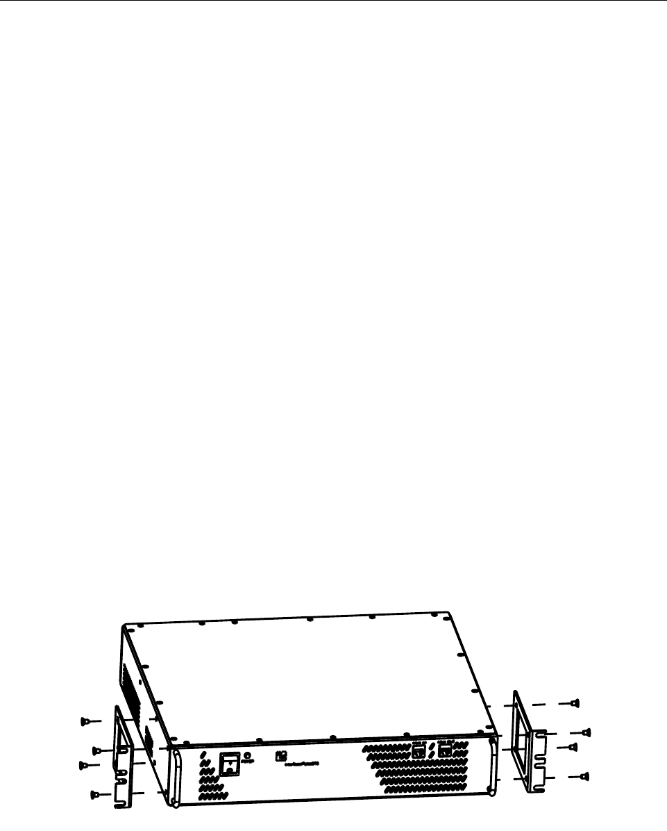
2.2.3 INSTALLATION INSTRUCTIONS
1 Using the screws provided. attach a mounting bracket to each side of the picoBTS, as
shown in Figure 2-1.
2 The rack mount brackets have cutouts to accommodate the 19" (48.26 cm) rack screws.
Using two people, carefully align the chassis with the rack holes.
Figure 2-1: Mounting Brackets
AD235807
Preliminary
InterReach picoBTS Installation Guide Page 11
© 2008, ADC Telecommunications, Inc.
ADCP-77-061 • Issue A • 08/2008 • Chapter 2 - Installation
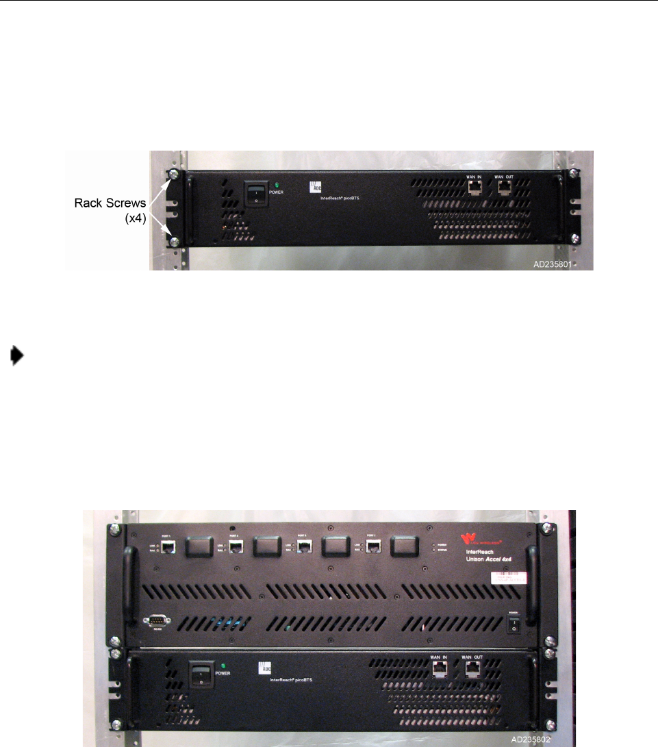
3 Carefully mount and secure the picoBTS using customer-provided rack screws, as shown
in Figure 2-2
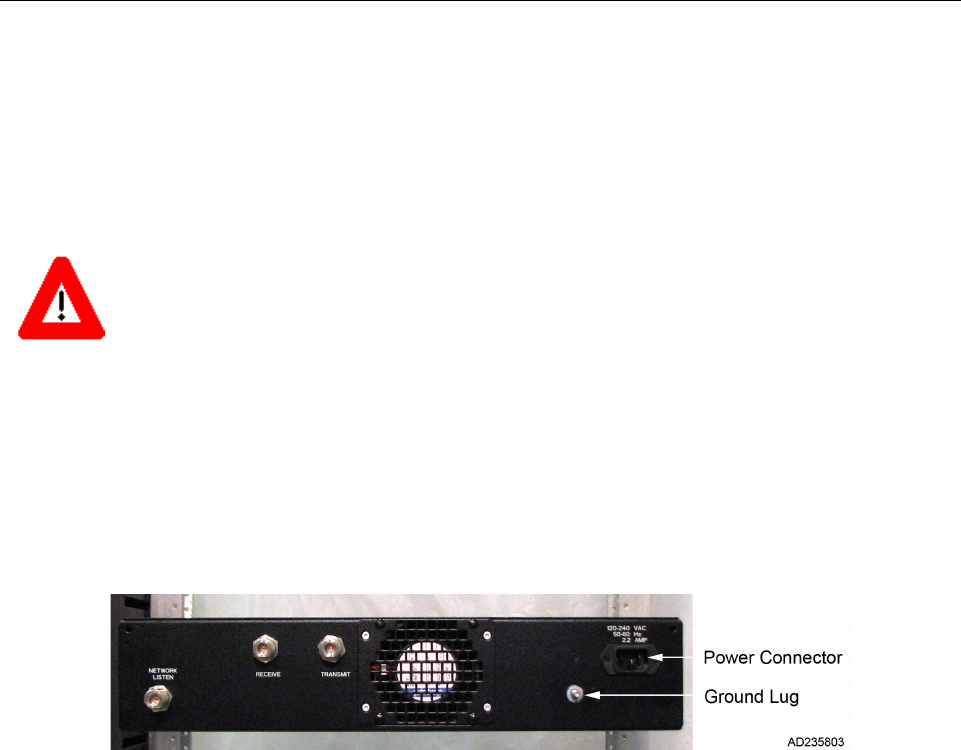
4 If you are mounting an InterReach Unison or Fusion DAS hub, use the same procedure to
align and mount the unit directly above or below the picoBTS in the rack using
customer-provided screws. Figure 2-3 shows a DAS hub mounted in a rack with a
picoBTS.
5 You have completed the hardware installation, proceed to the next section to continue the
picoBTS connections.
Figure 2-2: picoBTS Rack Mount
Note: Ensure that all rack mount screws are securely tightened.
Figure 2-3: picoBTS and DAS Mounting Location
Preliminary
Page 12 InterReach picoBTS Installation Guide
© 2008, ADC Telecommunications, Inc.
ADCP-77-061 • Issue A • 08/2008 • Chapter 2 - Installation
2.3 CONNECTING THE GROUNDING CABLE
Use this section to connect your earth ground and power cable to the picoBTS cabinet.
The rack unit in which the picoBTS chassis is being mounted should be properly grounded to
the site earth ground ring. You must attach a ground strap to each subrack and to the rack unit
or directly to the site ground ring.
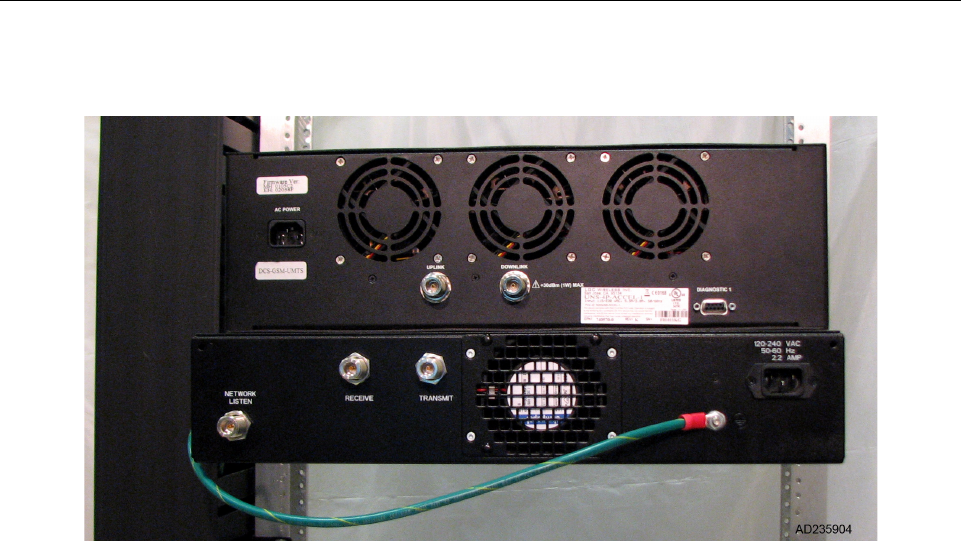
1 Locate the ground lug on chassis. See Figure 2-4 for its location.
2 Remove the nut from the ground lug and connect a ground lead to the chassis. Secure the
nut tightly on each subrack assembly using a 7/16 (11mm) wrench as shown in Figure 2-5.
Caution: Grounding circuit continuity is vital for safe operation of machine. Never operate machine
with grounding conductor disconnected.
Attention: Un circuit de terre continu est essentiel en vue du fonctionnement sécuritaire de l'appareil.
Ne jamais metre l'appareil en marche lorsque le cable de mise à la terre est débranche.
Warnung: Achtung, Hoher Ableitstrom! Schutzleiteranschluß vor dem Netzanschluß herstellen.
Figure 2-4: picoBTS Ground Lug and Power Connector
Preliminary
InterReach picoBTS Installation Guide Page 13
© 2008, ADC Telecommunications, Inc.
ADCP-77-061 • Issue A • 08/2008 • Chapter 2 - Installation
3 Attach the ground cables to the properly grounded rack assembly or to the closest earth
ground bus.
Figure 2-5: Ground Cable Connection
Preliminary
Page 14 InterReach picoBTS Installation Guide
© 2008, ADC Telecommunications, Inc.
ADCP-77-061 • Issue A • 08/2008 • Chapter 2 - Installation
2.4 CONNECTING THE POWER SUPPLY
In this section, you will connect the picoBTS to your power source.
1 Verify the ground connection you made in Section 2.3 is secure.
2 Make sure that the power switch located on the front of the chassis in the OFF (0)position.
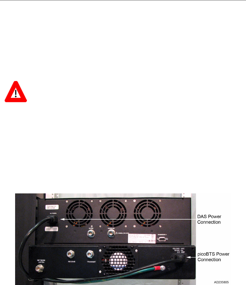
3 Use a local IEC standard power cable to connect the power connector shown in Figure 2-4
to your AC power supply. Figure 2-6 shows the power connection to both the picoBTS
and DAS systems.
4Do not apply power to the chassis at this time. Wait until you are performing the
commissioning procedures in the next chapter.
Warning: This product relies on the building's installation for short-circuit (overcurrent) protection.
Ensure that a fuse or circuit breaker no larger than 220 VAC, 1A; 110 VAC, 1A is used on the phase
conductors (all current-carrying conductors).
Attention: Pour ce qui est de la protection contre les courts-circuits (surtension), ce produit dépend de
l'installation électrique du local. Vérifier qu'un fusible ou qu'un disjoncteur de 220 VAC, 1A alt., 110
VAC, 1A alt. est utilisé sur les conducteurs de phase (conducteurs de charge).
Warnung: Dieses Produkt ist darauf angewiesen, daß im Gebäude ein Kurzschluß- bzw. Überstrom-
schutz installiert ist. Stellen Sie sicher, daß eine Sicherung oder ein Unterbrecher von nicht mehr als
220 V Wechselstrom, 1 A; 110 V Wechselstrom, 1 A an den Phasenleitern (allen stromführenden
Leitern) verwendet wird.
Figure 2-6: Power Supply Connection
Preliminary

InterReach picoBTS Installation Guide Page 15
© 2008, ADC Telecommunications, Inc.
ADCP-77-061 • Issue A • 08/2008 • Chapter 2 - Installation
Caution: The power supply cord is used as the main disconnect device, ensure that the socket-outlet is
located/installed near the equipment and is easily accessible.
Attention: Le cordon d'alimentation est utilisé comme interrupteur général. La prise de courant doit
être située ou installée à proximité du matériel et être facile d'accés.
Warnung: Das Netzkabel dient als Netzschalter. Stellen Sie sicher, das die Steckdose einfach zugän-
glich ist.
Preliminary
Page 16 InterReach picoBTS Installation Guide
© 2008, ADC Telecommunications, Inc.
ADCP-77-061 • Issue A • 08/2008 • Chapter 2 - Installation
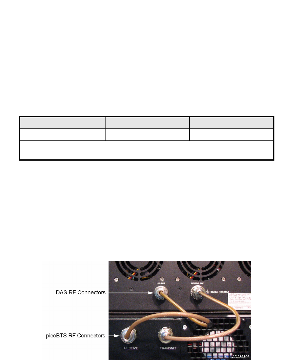
2.5 CONNECTING THE DISTRIBUTED ANTENNA SYSTEM
The chassis provides access to the female N-type connectors for your distributed antenna
system (DAS) or other external antennas.
The antenna cabling for the picoBTS will typically be configured for connection to an Inter-
Reach DAS system. Your site specific DAS system and configuration was determined during
the network planning stage of implementation.
1 Verify the power is OFF on both the picoBTS and DAS chassis.
2 Using one RF cable, connect the TRANSMIT N-type connector on the picoBTS to the
DOWNLINK connector on the DAS chassis. Tighten the connectors by hand until snug.
3 Using the second RF cable, connect the RECEIVE connector on the picoBTS to the
UPLINK connector on the DAS chassis. Tighten the connectors by hand until snug.
4Figure 2-7 illustrates the connections between the picoBTS and the DAS. Verify the
connections are correct and all connectors are tight.
Table 2-5: Adapters and Cabling
IDENTITY CABLE TYPE CORRESPONDING CABLE PLUGS
RF cable (15 in.) Coaxial N-type, Male
Note: Two 15 inch cables are provided to connect the picoBTS to a DAS. If your configuration is
different from the standard installation, you must provide the proper RF cables.
Figure 2-7: Antenna Cabling for Standard picoBTS Configurations
Preliminary

InterReach picoBTS Installation Guide Page 17
© 2008, ADC Telecommunications, Inc.
ADCP-77-061 • Issue A • 08/2008 • Chapter 2 - Installation
WARNING: All RF cabling must be completed with the chassis powered off and, preferably, with the
power cable disconnected from the cabinet.
Do not disconnect RF coaxial connectors on the ADC equipment or antenna systems while the radio
equipment is operating. Never place any body part over or look into any RF connector while the radio
equipment is transmitting.
RF signal levels that give rise to hazardous radiation levels can exist within the transmitter, power
amplifiers, associated RF multiplexers and antenna systems.
Preliminary
Page 18 InterReach picoBTS Installation Guide
© 2008, ADC Telecommunications, Inc.
ADCP-77-061 • Issue A • 08/2008 • Chapter 2 - Installation
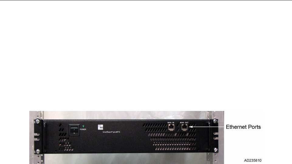
2.6 NETWORK CONNECTION
External cabling is dependent upon the customer site-specific requirements. The picoBTS
system carries OAM and VoIP traffic over Ethernet and should be connected on an isolated
Ethernet subnet for best performance.
The picoBTS has two 100baseT RJ-45 connectors Ethernet connection on the front panel
labeled WAN IN and WAN OUT, as shown in Figure 2-8.
•To make the connection, an Ethernet patch cable into the port and set up the Ethernet
connection as described in Section 3.3.
Figure 2-8: Network Connection
Preliminary

InterReach picoBTS Installation Guide Page 19
© 2008, ADC Telecommunications, Inc.
ADCP-77-061 • Issue A • 08/2008 • Chapter 2 - Installation
2.7 POST INSTALLATION CABLING AND CHECKS
Before proceeding to the next chapter and commissioning the equipment, make sure that:
•The chassis and mounting rack are properly grounded.
•The power cable is properly connected to the chassis and input power supply.
•The chassis power is turned off.
Preliminary

Page 20 InterReach picoBTS Installation Guide
© 2008, ADC Telecommunications, Inc.
ADCP-77-061 • Issue A • 08/2008 • Chapter 2 - Installation
Blank
Preliminary

InterReach picoBTS Installation Guide Page 21
© 2008, ADC Telecommunications, Inc.
ADCP-77-061 • Issue A • 08/2008 • Chapter 3 - Commissioning and Configuration
CHAPTER 3 - COMMISSIONING AND CONFIGURATION
3.1 PRE-COMMISSIONING . . . . . . . . . . . . . . . . . . . . . . . . . . . . . . . . . . . . . . . . . . . . . . . . . . . . . . . . . . . . . . . . . 23
3.1.1 On-Site Visual Inspection . . . . . . . . . . . . . . . . . . . . . . . . . . . . . . . . . . . . . . . . . . . . . . . . . . . . . . . 23
3.2 COMMISSIONING OF THE PICOBTS . . . . . . . . . . . . . . . . . . . . . . . . . . . . . . . . . . . . . . . . . . . . . . . . . . . . . . . . . 24
3.2.1 Connecting the PC to the picoBTS Chassis . . . . . . . . . . . . . . . . . . . . . . . . . . . . . . . . . . . . . . . . . . . . 24
3.2.2 Setting Up a Serial Connection to the picoBTS Serial Port . . . . . . . . . . . . . . . . . . . . . . . . . . . . . . . . . 24
3.2.3 Power On LED Tests . . . . . . . . . . . . . . . . . . . . . . . . . . . . . . . . . . . . . . . . . . . . . . . . . . . . . . . . . . . 26
3.3 CONFIGURING THE ETHERNET ADDRESS AND BOOT PARAMETERS . . . . . . . . . . . . . . . . . . . . . . . . . . . . . . . . . . 28
3.4 SOFTWARE VERIFICATION . . . . . . . . . . . . . . . . . . . . . . . . . . . . . . . . . . . . . . . . . . . . . . . . . . . . . . . . . . . . . . 31
3.4.1 Verifying the Current Software Version and Patch Level . . . . . . . . . . . . . . . . . . . . . . . . . . . . . . . . . . . 31
3.4.2 Verifying the Software License . . . . . . . . . . . . . . . . . . . . . . . . . . . . . . . . . . . . . . . . . . . . . . . . . . . . 32
3.4.3 Rebooting the picoBTS . . . . . . . . . . . . . . . . . . . . . . . . . . . . . . . . . . . . . . . . . . . . . . . . . . . . . . . . . 32
3.4.4 Terminating Serial Communications with the picoBTS . . . . . . . . . . . . . . . . . . . . . . . . . . . . . . . . . . . . 33
3.5 PREPARING FOR ON-LINE COMMISSIONING . . . . . . . . . . . . . . . . . . . . . . . . . . . . . . . . . . . . . . . . . . . . . . . . 3333
***********THIS CHAPTER IS TBD AND WILL INCLUDE BASIC NANO SETUP.
This material is currently covered in ADCP 75-310 Issue 2.
Content Page
Preliminary
Page 22 InterReach picoBTS Installation Guide
© 2008, ADC Telecommunications, Inc.
ADCP-77-061 • Issue A • 08/2008 • Chapter 3 - Commissioning and Configuration
The commissioning process includes the following steps:
•Pre off-line commissioning, where you ensure that the system is in an appropriate state.
This includes:
- Visual inspection
- Compliance checks
•Startup Verification, where you verify that the system comes up correctly by observing the
LEDs on the front panel.
•Configuration includes setting up the site-specific local IP address for the picoBTS.
The rest of this chapter includes the detailed instructions for these steps.
WARNING: Under normal operating conditions, ADC Telecommunications radio equipment
complies with the limits for human exposure to radio frequency (RF) fields adopted by the Federal
Communications Commission (FCC). All ADC Telecommunications, Inc. radio equipment is designed
so that under normal working conditions radio frequency radiation directly from the radio is negligible
when compared with the permissible limit of continuous daily exposure recommended in the United
States of America by ANSI/IEEE C95.1-19991 (R1997), Safety Levels with Respect to Human
Exposure to Radio Frequency Electromagnetic Fields, 3 kHz to 300 GHz.
Radio frequency signal levels that give rise to hazardous radiation levels can exist within the transmit-
ter, power amplifiers, associated RF multiplexers and antenna systems.
Do not disconnect RF coaxial connectors on the ADC equipment or antenna systems while the radio
equipment is operating. Never place any body part over or look into any RF connector while the radio
equipment is transmitting.
Caution: The BSS software used in the is highly complex. Before proceeding, contact Customer
Service to verify that you have the latest available software. You must have the correct software
CD-ROM and know the current patch level for your software version before commissioning the
picoBTS. Contact your Level 2 support representative for additional assistance.
Preliminary

InterReach picoBTS Installation Guide Page 23
© 2008, ADC Telecommunications, Inc.
ADCP-77-061 • Issue A • 08/2008 • Chapter 3 - Commissioning and Configuration
3.1 PRE-COMMISSIONING
This section must be completed before doing the commissioning. The commissioning of the
chassis should take place on-site after the physical installation of the picoBTS. Use the appro-
priate lists depending on where the off-line commissioning is being performed.
3.1.1 ON-SITE VISUAL INSPECTION
If you are doing your visual inspection on-site, check that:
•The chassis has been securely installed at the appropriate site.
•The power to the chassis is OFF.
•The chassis is connected to a suitable power source.
•The chassis is correctly grounded.
•All cables are available and secured in their correct positions.
Caution: DO NOT turn the power supply ON until you have a DAS or external antenna connected to
EACH antenna port.
Preliminary

Page 24 InterReach picoBTS Installation Guide
© 2008, ADC Telecommunications, Inc.
ADCP-77-061 • Issue A • 08/2008 • Chapter 3 - Commissioning and Configuration
3.2 COMMISSIONING OF THE PICOBTS
This section describes the commissioning procedures for the picoBTS. It includes Power-on
LED tests and software verification procedures. These check and configure the software and
run power on self tests (POST) and check the results.
In this chapter, you will use a laptop PC or other computer with serial session capability to
verify the software configuration and other aspects of the picoBTS operation.
3.2.1 CONNECTING THE PC TO THE PICOBTS CHASSIS
You will be making a serial connection from the laptop computer to the picoBTS. This con-
nection is used for checking the software version installed on the system, verifying and
changing boot parameters and monitoring test results.
3.2.1.1 Required Hardware
The following hardware is required to connect the laptop to the picoBTS using a serial
connection.
•One standard DB9 to DB9 serial cable
•Laptop USB to DB9 serial adapter (if necessary)
3.2.2 SETTING UP A SERIAL CONNECTION TO THE PICOBTS SERIAL PORT
1 Connect one end of the serial cable to picoBTS connector labeled Serial on the rear of
the chassis.
2 Connect the opposite end of the cable to the DB9 serial connector or serial adapter on the
laptop, as shown in Figure 3-2.
The PC uses serial communications for basic control of the picoBTS, including bootChange
configuration and monitoring of the boot-up process.
Figure 3-1: Connecting to the Serial Port
Preliminary
InterReach picoBTS Installation Guide Page 25
© 2008, ADC Telecommunications, Inc.
ADCP-77-061 • Issue A • 08/2008 • Chapter 3 - Commissioning and Configuration
1 If not already done, connect the laptop to the picoBTS as described in Section 3.2.2,.
2 You may use any available application to open a serial connection. This procedure
decribes how to use HyperTerminal. Navigation to the program may differ depending on
the operating system you have installed.
A Launch the application by navigating: Start -> Programs -> Accessories ->
HyperTerminal -> HyperTerminal
BEnter
BSS for the connection name and select an icon. Then click the OK button.
C The Connect To dialog box displays. Select COM1 from the Connect using
drop-down list. If you know that your serial port is configured on a different port,
select that port from this drop-down list.
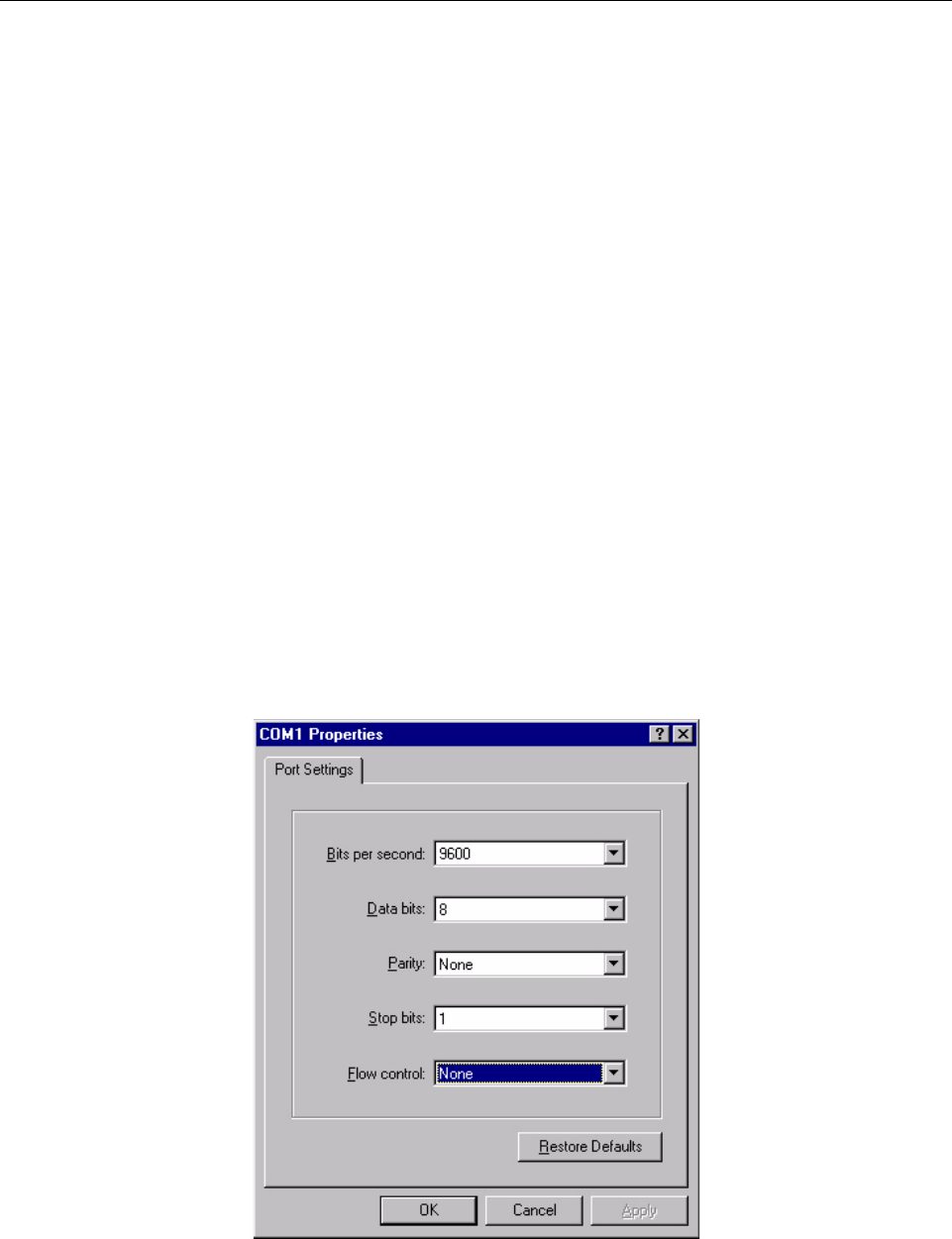
D The COM1 Properties dialog box displays. Set the following properties and click the
OK button. See Figure 3-2.
Bits per second: 9600
Data bits: 8
Parity: None
Stop bits: 1
Flow control: None
Figure 3-2: Serial Session Properties
Preliminary
Page 26 InterReach picoBTS Installation Guide
© 2008, ADC Telecommunications, Inc.
ADCP-77-061 • Issue A • 08/2008 • Chapter 3 - Commissioning and Configuration
E Select OK to connect to the chassis. At this time, you will not see a prompt. Proceed
to Section 3.2.3 to power on the chassis.
3.2.3 POWER ON LED TESTS
This section describes how to power-on the picoBTS and verify that the system comes up
properly by viewing the LEDs on the front of the chassis. The purpose of these tests is to verify
that the LEDs come up in the correct state, indicating that the system is operating normally.
Use the following procedure:
1 Turn the power to the chassis on by switching on the power switch on the front panel.
2 Verify that the front-panel LEDs flash in the sequence shown in Figure 3-3.
3 When the sequence is completed, verify that the LEDs appear as shown in the following
table:
4 If your LEDs appear as described above, you are done with the LED Power up tests.
Contact Customer Service.
Caution: DO NOT turn this power supply on until you have a DAS system or an external antenna con-
nected to EACH antenna port.
Figure 3-3: LED Sequence During the Boot Process
Table 3-1: LED Normal Indications
LED DESCRIPTION
PWR
Green LED, lit when system has power supplied.
The PWR LED of the controller and TRX cards will be lit after all cards have completed
the boot-up process.
ON LINE
Green LED, lit when card is on-line, and card BOOT process has been performed
successfully.
The On-Line LED of the Controller card will be lit after all cards have completed the
boot-up process.
The TRX cards will not go on-line until they are unlocked by the OMC operator
FLT Red LED, lit when card detects a fault or is not downloaded.
Preliminary

InterReach picoBTS Installation Guide Page 27
© 2008, ADC Telecommunications, Inc.
ADCP-77-061 • Issue A • 08/2008 • Chapter 3 - Commissioning and Configuration
5 You can monitor the status of the boot process using the serial session opened in
Section 3.4.
Once the LEDs on the processor cards have reached their final online status, press the
[ENTER] key in the HyperTerminal window. The prompt now changes to the following:
HD:iwbox->
Preliminary

Page 28 InterReach picoBTS Installation Guide
© 2008, ADC Telecommunications, Inc.
ADCP-77-061 • Issue A • 08/2008 • Chapter 3 - Commissioning and Configuration
3.3 CONFIGURING THE ETHERNET ADDRESS AND BOOT PARAMETERS
In this section, you configure the boot parameters to modify the IP address of the system. After
changing the boot parameters, the chassis must be reset before the changes take effect.
1 If not already done, establish serial communications with the picoBTS as described in
Section 3.2.2.
2 Once the picoBTS boots normally, press the [ENTER] key to show the prompt:
HD:iwbox->
3 Display the boot parameters, by typing:
bootChange [ENTER]
4 The boot parameters display individually after pressing the [ENTER] key. Each param-
eter can be modified by simply entering the new values after the existing value is
displayed and pressing the [ENTER] key. You cannot use the backspace or delete keys in
this window. Edit the parameter values using the following commands:
Figure 3-4 shows the default bootChange parameters for the system.
Table 3-2: Changing Boot Parameters
COMMAND ACTION
[ENTER] Accepts the current parameter value and proceeds to the next parameter.
. [ENTER] Erases the current parameter value and proceeds to the next parameter.
- [ENTER] Returns to the previous parameter.
[CTRL][d] Aborts all changes and reverts to the current values.
Preliminary

InterReach picoBTS Installation Guide Page 29
© 2008, ADC Telecommunications, Inc.
ADCP-77-061 • Issue A • 08/2008 • Chapter 3 - Commissioning and Configuration
It is necessary to change the default picoBTS Ethernet address to match your site-specific
network configuration. Use the following steps to modify the IP address and target name of the
picoBTS.
5 Type the bootChange command to edit the boot parameters. The parameters will be
displayed one line at a time.
bootChange [ENTER]
'.' = clear field; '-' = go to previous field; ^D = quit
boot device : ata.0
processor number : 0
host name :
file name : hd0:/vxWorks
inet on ethernet (e) : 172.16.80.42:fffff000
inet on backplane (b):
host inet (h) :
gateway inet (g) :
user (u) : target
ftp password (pw) (blank = use rsh):
flags (f) : 0x0
target name (tn) : iwbox
startup script (s) : /hd0/iwvstart
other (o) : motfcc
value = 0 = 0x0
HD:iwbox-> _
Figure 3-4: Default Boot Parameters
'.' = clear field; '-' = go to previous field; ^D = quit
boot device : ata.0
processor number : 0
host name :
file name : hd0:/vxWorks
inet on ethernet (e) : XXX.XXX.XXX.XXX:fffff000
inet on backplane (b):
host inet (h) :
gateway inet (g) : YYY.YYY.YYY.YYY
user (u) :
ftp password (pw) (blank = use rsh):
flags (f) : 0x0
target name (tn) : TARGETNAME
startup script (s) : /hd0/iwvstart
other (o) : motfcc
value = 0 = 0x0
HD:iwbox-> _
Figure 3-5: Boot Parameters Requiring Changes
Preliminary
Page 30 InterReach picoBTS Installation Guide
© 2008, ADC Telecommunications, Inc.
ADCP-77-061 • Issue A • 08/2008 • Chapter 3 - Commissioning and Configuration
6Figure 3-5 shows the IP address parameters which must be modified to add your picoBTS
to your Ethernet network.
-XXX.XXX.XXX.XXX is the IP address. Replace it with the site-specific Ethernet IP
address for your network. The IP address is followed by ‘:fffff000’ which is the
subnet mask as a hexadecimal value. To modify the subnet mask of the processor
card, determine the proper hexadecimal value and enter following the colon. For
example to use a subnet of 255.255.255.0, you would follow the IP address with
‘:ffffff00’. The value displayed in the example ‘:fffff000’ is equal to
255.255.240.0.
-YYY.YYY.YYY.YYY is the gateway router IP address. Enter the IP address of the
gateway router.
- TARGET NAME sets the IP name. The default is “iwbox”. The TARGET NAME
parameter sets the IP name. The default is “iwbox”. You should enter a different name
for each system.
7 Ensure that all other boot parameters are configured exactly as shown in the previous
figures.
8 If you have changed anything, for the new parameters to take effect, reboot the chassis by
pressing the key combination [CTRL][x]. If you do not receive a prompt after reboot,
press [ENTER] to display the HD:iwbox-> prompt.
9 Connect an Ethernet RJ-45 patch cable to the WAN port on the front of hte chassis.
10 Notify the OMC operator that the picoBTS is connected to the Ethernet, and give the
OMC operator the IP address and IP Name.
Note: Use the IP name and IP address you received from your network administrator.
Caution: You should ONLY change the inet on ethernet, target name and gateway
inet parameters. All other parameters should NOT be modified.
Caution: The OMC operator MUST have the correct picoBTS IP address, or the OMC will not be
able to communicate with the BS Plus.
Preliminary

InterReach picoBTS Installation Guide Page 31
© 2008, ADC Telecommunications, Inc.
ADCP-77-061 • Issue A • 08/2008 • Chapter 3 - Commissioning and Configuration
3.4 SOFTWARE VERIFICATION
You should use the following commissioning procedures to verify the software installed on the
picoBTS.
3.4.1 VERIFYING THE CURRENT SOFTWARE VERSION AND PATCH LEVEL
1 If not already done, establish serial communications with the picoBTS as described in
Section 3.2.2.
2After the HD:iwbox-> prompt appears, verify the current software version and patch
level by typing:
iwversion [ENTER]
The following software information will be displayed:
BSC code version: iw07_05.ZZZ
Release number: 7.5
ABIS version: 1.1
Packages Installed:
Encryption: A5/1
Patches Installed:
patch<#> <file directory> <patch size> <iw07_05.ZZZ>
The current software version is displayed, represented above by the parameter iw07_05.ZZZ.
This number should correspond to the software version detailed in the release notes included
with the CD-ROM. Keep this number for your records.
3 Verify under Patches Installed: that the most current patch is installed, if appli-
cable. Refer to the GSM Craft PC User Guide for procedures to install required patches. If
you are unsure if you require software patches, contact your Level 2 support representa-
tive for additional assistance.
Note: The following section describes procedures performed using the Craft PC. For more information
pertaining to the use of the Craft PC, please refer to the GSM Craft PC User Guide.
Note: If the displayed software version number does not coincide with the software version being run
on the network for which this picoBTS is going to be used, contact Customer Service for instructions
on how to install a different software version.
Preliminary

Page 32 InterReach picoBTS Installation Guide
© 2008, ADC Telecommunications, Inc.
ADCP-77-061 • Issue A • 08/2008 • Chapter 3 - Commissioning and Configuration
3.4.2 VERIFYING THE SOFTWARE LICENSE
In this section you will complete the following procedures:
•Backup the software license files from the processor card to the PC or OMC.
•Verify the software license files are compatible with the system.
1 Verify the serial cable is connected to the chassis and you have an open serial session as
detailed in Section 3.2.2.
2 Verify the license file using the following command:
printLicenseKey
The following output is a sample of properly configured license file:
License Keys :
printLicenseKey
GENERAL : VALID
GPRS : VALID
FREQHOP : VALID
XTNDCELL : VALID
SECTOR : VALID
TRX_84 : VALID
PDCH_60 : VALID
value = 1 = 0x1
HD:iwbox-> Done.
The licenses will vary depending based on your sales order and your network
configuration. Your license will not have all of the the entries listed above and may
display an error message similar to the following:
1219117434.733 (tShell) VerifyKey: key not found 4
This is normal, however if your license does not have any VALID entries. The file may be
corrupt or not properly installed, contact Customer Service.
3.4.3 REBOOTING THE PICOBTS
•Using the serial session window, reboot the picoBTS by typing:
reboot [ENTER]
The entire chassis will now reboot.
Preliminary

InterReach picoBTS Installation Guide Page 33
© 2008, ADC Telecommunications, Inc.
ADCP-77-061 • Issue A • 08/2008 • Chapter 3 - Commissioning and Configuration
3.4.4 TERMINATING SERIAL COMMUNICATIONS WITH THE PICOBTS
•To terminate serial communications, use the disconnect menu within HyperTerminal or
other application.
3.5 PREPARING FOR ON-LINE COMMISSIONING
The following procedure is necessary to ensure that the picoBTS is ready for use and ready for
on-line testing.
1 Power on the picoBTS if it is not already on. Verify that all PWR and On-Line LEDs are
green.
2 Using the appropriate documentation, ensure the distributed antenna system (DAS) is
properly connected, cabled and configured.
3 Inform the OMC operator that the picoBTS is ready for network configuration.
4 After the OMC operator has configured the picoBTS, continue with on-line commis-
sioning tests in the next chapter.
Preliminary

Page 34 InterReach picoBTS Installation Guide
© 2008, ADC Telecommunications, Inc.
ADCP-77-061 • Issue A • 08/2008 • Chapter 3 - Commissioning and Configuration
Blank
Preliminary

InterReach picoBTS Installation Guide Page 35
© 2008, ADC Telecommunications, Inc.
ADCP-77-061 • Issue A • 08/2008 • Chapter 4 - On-Line Testing
CHAPTER 4 - ON-LINE TESTING
4.1 PRE ON-LINE COMMISSIONING REQUIREMENTS . . . . . . . . . . . . . . . . . . . . . . . . . . . . . . . . . . . . . . . . . . . . . . . 36
4.2 ON-LINE COMMISSIONING . . . . . . . . . . . . . . . . . . . . . . . . . . . . . . . . . . . . . . . . . . . . . . . . . . . . . . . . . . . . . . 37
4.2.1 Testing the picoBTS . . . . . . . . . . . . . . . . . . . . . . . . . . . . . . . . . . . . . . . . . . . . . . . . . . . . . . . . . . . 39
4.2.2 Recovery Tests . . . . . . . . . . . . . . . . . . . . . . . . . . . . . . . . . . . . . . . . . . . . . . . . . . . . . . . . . . . . . . . 39
4.2.3 TCH Timeslot Tests . . . . . . . . . . . . . . . . . . . . . . . . . . . . . . . . . . . . . . . . . . . . . . . . . . . . . . . . . . . . 39
4.2.4 RX Signal Quality Measurements . . . . . . . . . . . . . . . . . . . . . . . . . . . . . . . . . . . . . . . . . . . . . . . . . . 40
4.3 POST ON-LINE COMMISSIONING PROCEDURES . . . . . . . . . . . . . . . . . . . . . . . . . . . . . . . . . . . . . . . . . . . . . . . . 42
On-line commissioning tests the air interface to the picoBTS and takes place on-site after
installation and commissioning. Its purpose is to verify that the equipment is operational and
can be integrated into the telecommunications network.
On-line commissioning requires the participation of one or two people; a field technician who
operates and tests the picoBTS on-site and an OMC-R operator who has commissioned the
picoBTS on the BSC. These two must work together to get the RF interface up and the system
ready to make calls.
Content Page
Radio Frequency Radiation Warning
Under normal operating conditions, ADC radio equipment complies with the limits for human exposure
to radio frequency (RF) fields adopted by the Federal Communications Commission (FCC). All ADC
Telecommunications, Inc. radio equipment is designed so that under normal working conditions RF
radiation directly from the radio is negligible when compared with the permissible limit of continuous
daily exposure recommended in the United States of America by ANSI/IEEE C95.1-19991 (R1997),
Safety Levels with Respect to Human Exposure to Radio Frequency Electromagnetic Fields, 3 kHz to
300 GHz.
RF signal levels that give rise to hazardous radiation levels can exist within the transmitter, power
amplifiers, associated RF multiplexers and antenna systems.
Do not disconnect RF coaxial connectors on the ADC equipment or antenna systems while the radio
equipment is operating. Never place any body part over, or look into any RF connector while the radio
equipment is transmitting.
Preliminary

Page 36 InterReach picoBTS Installation Guide
© 2008, ADC Telecommunications, Inc.
ADCP-77-061 • Issue A • 08/2008 • Chapter 4 - On-Line Testing
4.1 PRE ON-LINE COMMISSIONING REQUIREMENTS
Before on-line commissioning begins, the field technician or the OMC-R operator must verify
that:
•The picoBTS, BSC and the MSC are fully commissioned, in service and connected to each
other.
•The BSC is in service and connected to the picoBTS.
•The OMC-R operator has successfully created and configured the picoBTS object on the
OMC-R and downloaded this information to the picoBTS. Refer to the procedures
described in the FlexWave BSS documentation.
•The RF frequencies are cleared to transmit.
•The BSC-picoBTS Ethernet link is properly configured and operational.
•The HLR subscriber data has been entered into the MSC HLR. In particular, the HLR
must be configured to support the SIM cards of the mobiles used by the field technician.
Preliminary

InterReach picoBTS Installation Guide Page 37
© 2008, ADC Telecommunications, Inc.
ADCP-77-061 • Issue A • 08/2008 • Chapter 4 - On-Line Testing
4.2 ON-LINE COMMISSIONING
The network commissioning procedures must be performed using the OMC-R and with in the
coverage area provided by the picoBTS. This requires one or two persons working from at
least two different documentation sets:
•A field technician who is on-site within the coverage area of picoBTS and DAS system.
They must have a copy of this manual and the appropriate DAS documentation.
•An OMC-R operator who uses the FlexWave OMC-R or BSC Configuration Manager to
configure and enable the picoBTS in the network. They must have the appropriate
FlexWave documention for the procedures they are perfoming.
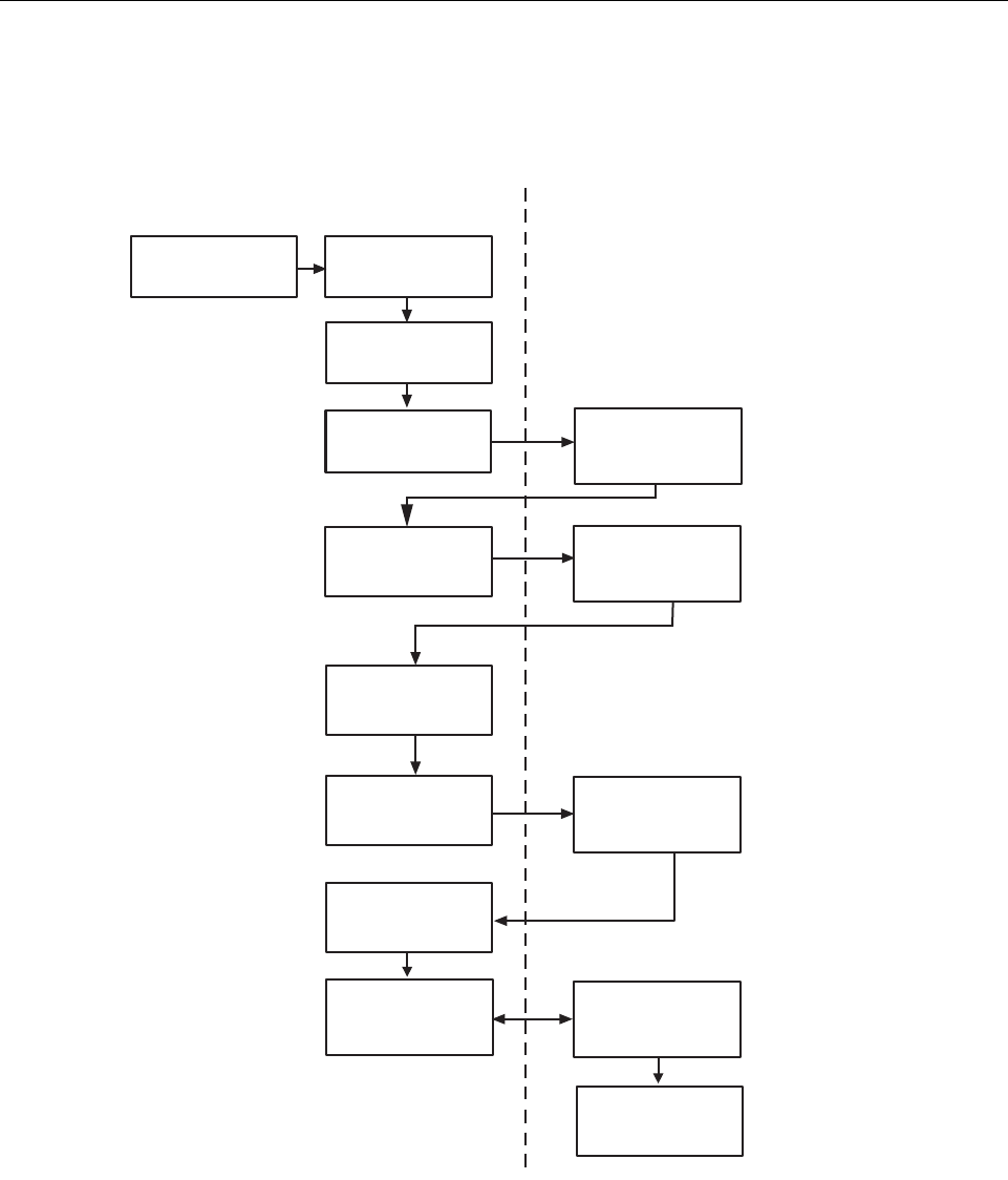
The flowchart shown in Figure 4-1 provides a high-level view of the procedures. The proce-
dures in the following sections provide detailed, numbered steps.
Note: Before starting any of the following procedures, the field technician needs to ensure that
anti-static precautions are taken. Refer to Section 1.2.
Preliminary
Page 38 InterReach picoBTS Installation Guide
© 2008, ADC Telecommunications, Inc.
ADCP-77-061 • Issue A • 08/2008 • Chapter 4 - On-Line Testing
Figure 4-1: On-Line Commissioning Procedures
Procedures for OMC Operator
AD235811
Procedures for Field
Technician (at picoBSS)
Step 2
Reconnect
WAN Cable
Step 1
Disconnect
WAN Link Cable
Configure Cell
Configure Abis
interface to BSC
Create picoBSS
on OMC or BSC
Verify
Status Changes
Check Alarm
Event Log
Check Alarm
Event Log
Enable Cell
Check State
Verify Test Calls Make Test Calls
Site Clean-up
Step 3
Check LEDs are
Green and Steady
Preliminary

InterReach picoBTS Installation Guide Page 39
© 2008, ADC Telecommunications, Inc.
ADCP-77-061 • Issue A • 08/2008 • Chapter 4 - On-Line Testing
4.2.1 TESTING THE PICOBTS
Before disconnecting the physical Ethernet cable, the field technician must make sure that the
cable is labeled in a way that clearly identifies its origin and destination.
•Provide the OMC-R operator with all part, revision and serial numbers for the picoBTS.
4.2.2 RECOVERY TESTS
The OMC-R operator should add the picoBTS to the GUI, configure the Abis to the BSC and
configure the Cell information on the OMC-R or BSC. Then perform the following steps:
1 At the picoBTS, disconnect the physical Ethernet cable.
2 Coordinate with the OMC-R operator to ensure the proper alarms have appeared on the
OMC-R.
3 Reconnect the physical Ethernet cable to the picoBTS.
4 Coordinate with the OMC-R operator to ensure the proper alarms have cleared on the
OMC-R.
4.2.3 TCH TIMESLOT TESTS
1 In this test, the OMC-R operator unlocks individual TCH timeslots and the field
technician places a mobile-to-mobile call over each timeslot using a mobile handset in
debug mode. Refer to the documentation provided by the module handset manufacturer
for the proper procedures.
For each timeslot, the commissioner should verify that:
- The timeslot displayed on the handset corresponds to the timeslot unlocked by the
OMC-R operator.
- A two-way call is completed successfully.
- The call has good audio quality and power, and low interference.
The number of timeslots to be tested will be for two TRXs. Table 4-1 provides the
sequence for two or more TRXs.
Table 4-1: Timeslots Requiring Testing in picoBTS
TRX NUMBER TIMESLOT NUMBER CHANNEL TYPE TESTING NECESSARY
First TRX (Note) 0 BCCH No
1 SDCCH No
2TCHYes
3TCHYes
4TCHYes
Preliminary

Page 40 InterReach picoBTS Installation Guide
© 2008, ADC Telecommunications, Inc.
ADCP-77-061 • Issue A • 08/2008 • Chapter 4 - On-Line Testing
4.2.4 RX SIGNAL QUALITY MEASUREMENTS
The objectives of this test are to verify the performance of the Receive path of the picoBTS
and the operation of the RX module in the TRX. Before these tests can take place, the picoBTS
must be returned to its original “on air” working state with call processing possible.
1 From an Xterm window on the OMC-R, telnet to the picoBTS to be tested, or alternatively
connect directly using a serial session to the picoBTS with the laptop PC.
THIS SECTION FROM HERE IS TOO BE DETERMINED.
2 From the picoBTS prompt type the following to activate the RX RSSI and quality data
logging:
HD:iwbox-> log_none [ENTER]
HD:iwbox-> ho_log_on_bts [ENTER]
5TCHYes
6TCHYes
7TCHYes
Second TRX (Note) 0 TCH Yes
1TCHYes
2TCHYes
3TCHYes
4TCHYes
5TCHYes
6TCHYes
7TCHYes
Note: The BCCH can be assigned to any TRX within the picoBTS. The label “First TRX” applies to the
TRX to which is assigned the BCCH. All TCH timeslots on the secondTRX must be tested.
Table 4-1: Timeslots Requiring Testing in picoBTS, continued
TRX NUMBER TIMESLOT NUMBER CHANNEL TYPE TESTING NECESSARY
Preliminary

InterReach picoBTS Installation Guide Page 41
© 2008, ADC Telecommunications, Inc.
ADCP-77-061 • Issue A • 08/2008 • Chapter 4 - On-Line Testing
3 Place a mobile to mobile call through the BS Plus. The RSSI and Quality for the call will
be displayed, as illustrated in Figure 4-2.
The sample log shows typical results for strong signals on both the uplink and downlink where
RSSI of 63 is the highest number. The quality should generally be 0 when the RSSI is above
40 (strong signal). If you have any 2 or higher numbers in RX quality, you have some receiver
problems and should contact Customer Service.
210 (bts ) (4 0xe)UL:63/63 0/0 F AVG 63 0 DL:63/63 0/0 F AVG 63 0 NBR
211 (bts ) (4 0xe)UL:63/63 0/0 F AVG 63 0 DL:63/63 0/0 F AVG 63 0 NBR
212 (bts ) (4 0xe)UL:63/63 0/0 F AVG 63 0 DL:63/63 0/0 F AVG 63 0 NBR
213 (bts ) (4 0xe)UL:63/63 0/0 F AVG 63 0 DL:63/63 0/0 F AVG 63 0 NBR
214 (bts ) (4 0xe)UL:63/63 0/0 F AVG 63 0 DL:63/63 0/0 F AVG 63 0 NBR
215 (bts ) (4 0xa)UL:63/63 0/0 F AVG 61 0 DL:63/63 0/0 F AVG 63 0 NBR
216 (bts ) (4 0xe)UL:63/63 0/0 F AVG 63 0 DL:63/63 0/0 F AVG 63 0 NBR
217 (bts ) (4 0xa)UL:59/60 0/0 F AVG 62 0 DL:63/63 0/0 F AVG 63 0 NBR
218 (bts ) (4 0xe)UL:63/63 0/0 F AVG 63 0 DL:63/63 0/0 F AVG 63 0 NBR
Uplink RSSI/Quality Downlink RSSI/Quality
Figure 4-2: RSSI and Quality Log
Preliminary

Page 42 InterReach picoBTS Installation Guide
© 2008, ADC Telecommunications, Inc.
ADCP-77-061 • Issue A • 08/2008 • Chapter 4 - On-Line Testing
4.3 POST ON-LINE COMMISSIONING PROCEDURES
1 Leave the power to the OMC-R and picoBTS on.
2 Check that all power cable and ground connections are tight.
3 Ensure that the picoBTS site is left in a tidy state.
This concludes the commissioning of the picoBTS. The technician may now leave the
picoBTS site.
Preliminary

ADCP-77-061 • Issue A • 08/2008 • Back Cover
InterReach picoBTS Installation Guide Page 43
© 2008, ADC Telecommunications, Inc.
Blank
Preliminary
13944-P
Contents herein are current as of the date of publication. ADC reserves the right to change the contents
without prior notice. In no event shall ADC be liable for any damages resulting from loss of data,
loss of use, or loss of profits and ADC further disclaims any and all liability for indirect, incidental,
special, consequential or other similar damages. This disclaimer of liability applies to all products,
publications and services during and after the warranty period.
REPRINTS:
www.adc.com/manuals
PDF copies of manuals are available
for downloading at the following link:
PRODUCT INFORMATION AND TECHNICAL ASSISTANCE:
connectivity.tac@adc.com
wireless.tac@adc.com
euro.tac@adc.com
asiapacific.tac@adc.com
ADCP Number:
WRITE:
ADC Telecommunications (S’PORE) PTE, LTD;
100 Beach Road, #18-01, Shaw Towers.
Singapore 189702.
ADC Telecommunications, INC
PO Box 1101,
Minneapolis, MN 55440-1101, USA
ADC European Customer Service, INC
Belgicastraat 2,
1930 Zaventem, Belguim
PHONE:
U.S.A. or CANADA
Sales: 1-800-366-3691
Extension 73000
Technical Assistance: 1-800-366-3891
Connectivity Extension: 73475
Wireless Extension: 73476
EUROPE
Sales Administration: +32-2-712-65 00
Technical Assistance: +32-2-712-65 42
EUROPEAN TOLL FREE NUMBERS
Germany: 0180 2232923
UK: 0800 960236
Spain: 900 983291
France: 0800 914032
Italy: 0800 782374
ASIA/PACIFIC
Sales Administration: +65-6294-9948
Technical Assistance: +65-6393-0739
ELSEWHERE
Sales Administration: +1-952-938-8080
Technical Assistance: +1-952-917-3475
ADCP-77-061
Preliminary
Preliminary

Website: www.adc.com
Preliminary