ADC Telecommunications LAB2442A Long Range Wireless Transmitter User Manual LPS20X
ADC Telecommunications Inc Long Range Wireless Transmitter LPS20X
Contents
- 1. Users Manual Part 1
- 2. Users ManualPart 2
Users Manual Part 1
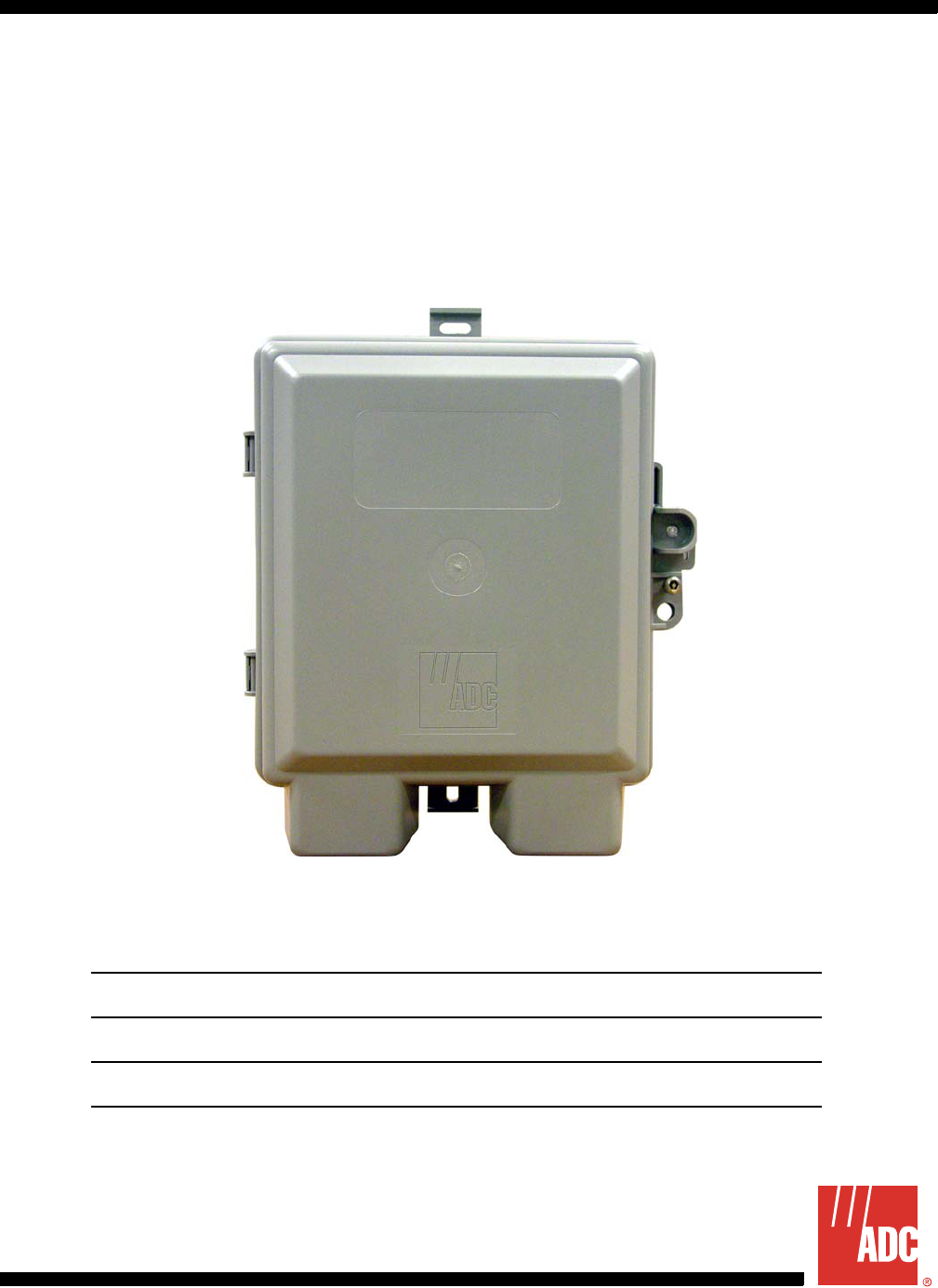
Section SCP-LPS20x-011-012-01H
LoopStar™ LPS-20xR
Span-Powered Access Point
Technical Practice
Model xDSL List CLEI Code
LPS-200R G.SHDSL 1A(x) WDMFA00A~~
LPS-200R G.SHDSL 1B(x) WDMFB00A~~
LPS-202R ADSL 1A(x) WDUIAAAA~~
LPS-202R ADSL 1B(x) WDUIAABA~~
12A-LPS20xR1

December 20, 2004 SCP-LPS20x-011-012-01H
ADC Telecommunications, Inc. i
REVISION HISTORY
Copyright © 2004 ADC Telecommunications, Inc. All Rights Reserved.
ADC is a registered trademark and LoopStar is a trademark of ADC Telecommunications, Inc. No right, license, or
interest to such trademarks is granted hereunder, and you agree that you shall assert no such right, license, or
interest with respect to such trademarks.
Wi-Fi is a registered trademark of the Wi-Fi Alliance.
Other product names mentioned in this document are used for identification purposes only and may be trademarks
or registered trademarks of their respective companies.
nformation contained in this document is company private to ADC Telecommunications, Inc., and ADC DSL
Systems, Inc., and shall not be modified, used, copied, reproduced or disclosed in whole or in part without the
written consent of ADC.
Contents herein are current as of the date of publication. ADC reserves the right to change specifications at any time
without notice. Information furnished by ADC is believed to be accurate and reliable. In no event shall ADC be liable
for any damages resulting from the loss of data, loss of use, or loss of profits and ADC further disclaims any and all
liability for indirect, incidental, special, consequential or other similar damages. This disclaimer of liability applies to
all products, publications and services during and after the warranty period.
Revision Release Date Revisions Made
01 December 20, 2004 Initial Release.
SCP-LPS20x-011-012-01H December 20, 2004
ii ADC Telecommunications, Inc.
USING THIS TECHNICAL PRACTICE
The following style conventions and terminology are used throughout this guide.
EU COMPLIANCE
This product has been CE marked in accordance with the requirements of European Directive 73/23/EEC; the
following mentioned product is in conformity with Low Voltage Directive 73/23/EEC in order to comply with the
requirements in the Council Directive 73/23/EEC relating to electrical equipment designed for use within certain
voltage limits and the Amendment Directive 93/68/EEC.
For safety evaluation of the compliance with this Directive 73/23/EEC, these standards were applied: IEC
60950:1999, EN 60950:2000.
INSPECTINGYOUR SHIPMENT
Upon receipt of the equipment:
• Unpack each container and visually inspect the contents for signs of damage. If the equipment has been dam-
aged in transit, immediately report the extent of damage to the transportation company and to ADC. Order
replacement equipment, if necessary.
• Check the packing list to ensure complete and accurate shipment of each listed item. If the shipment is short or
irregular, contact ADC as described in Product Support on page 177. If you must store the equipment for a pro-
longed period, store the equipment in its original container.
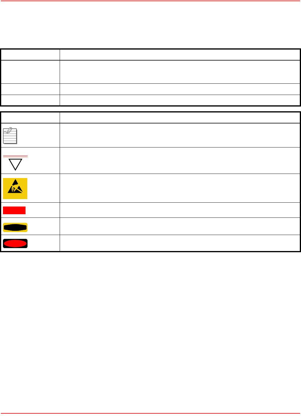
Element Meaning
Bold font Text that you must input exactly as shown (e.g., type 1 for card 1), menu buttons
(e.g., ACCEPT SHELF OPTIONS) or menu screen options (e.g., ALARMS screen) that you
must select
Italic font Variables that you must determine before inputting the correct value (e.g., Password )
Monospace font References to screen prompts (e.g., Invalid Password...Try Again:.)
Reader Alert Meaning
Alerts you to supplementary information
!
IMPORTANT Alerts you to supplementary information that is essential to the completion of a task
ATTENTION
Alerts you to possible equipment damage from electrostatic discharge
CAUTION Alerts you to possible data loss, service-affecting procedures, or other similar type problems
WARNING Alerts you that failure to take or avoid a specific action might result in hardware damage or
loss of service
DANGER Alerts you that failure to take or avoid a specific action might result in personal harm

Table of Contents
December 20, 2004 SCP-LPS20x-011-012-01H
ADC Telecommunications, Inc. iii
Revision History ...................................................................................................................... i
Using this Technical Practice ..................................................................................................ii
EU Compliance ................................................................................................................. ii
InspectingYour Shipment .................................................................................................. ii
Introduction ........................................................................................................................... 1
Overview ................................................................................................................................ 3
Description ............................................................................................................................ 4
Wi-Fi CO-Based DSLAM Deployment .................................................................................... 4
G.SHDSL Rate/Reach ....................................................................................................... 5
ADSL Rate/Reach ............................................................................................................. 6
LPS-20x ............................................................................................................................. 7
Specifications .......................................................................................................................... 8
Span-Powered xDSL Modem ................................................................................................. 11
Interface - (G.SHDSL) ....................................................................................................... 11
Interface (ADSL) ................................................................................................................ 11
ATM ................................................................................................................................... 12
DSL - Wide Area Network (WAN) Side ................................................................................... 13
ATM Internetworking Requirements (Table 8) ................................................................... 13
SNMP Management .......................................................................................................... 13
HTTP Management ........................................................................................................... 13
Software Download ................................................................................................................. 14
GUI Methods ..................................................................................................................... 14
SNMP Method ................................................................................................................... 14
Start-Up ............................................................................................................................. 14
Performance Monitoring .................................................................................................... 14
Wi-Fi LPS-20x ......................................................................................................................... 15
Wireless Interface .............................................................................................................. 15
IP Address .............................................................................................................................. 16
Output Power and Range ....................................................................................................... 16
Antenna ................................................................................................................................... 17
Installation and Test ............................................................................................................. 19
For equipment using an RFT circuit ....................................................................................... 19
Preparing the Unit ................................................................................................................... 19

SCP-LPS20x-011-012-01H December 20, 2004
iv ADC Telecommunications, Inc.
Mounting the Unit .................................................................................................................... 20
Open the Unit .......................................................................................................................... 20
Reference Labels .................................................................................................................... 21
Attach the Ground Wire .......................................................................................................... 22
Attach the xDSL Tip and Ring Wires ...................................................................................... 22
Using External Antenna(s) ......................................................................................................24
Attach External N-Type Single Antenna (Optional) ................................................................ 24
Attach External SMA-Type Antenna (Optional) ...................................................................... 25
System Status Window and LEDs .......................................................................................... 26
Reset Button ........................................................................................................................... 27
Restarting ........................................................................................................................ 28
Resetting to Factory Defaults ............................................................................................ 28
Close the Unit ......................................................................................................................... 28
Introduction to the Wireless Access Point .............................................................................. 29
Intelligent Bridge ..................................................................................................................... 29
Service Sensor ....................................................................................................................... 30
Roaming ................................................................................................................................. 30
MAC-Level Filtering ................................................................................................................ 30
Location-Aware Authentication ............................................................................................... 30
Wireless Bridging .................................................................................................................... 31
Multiple SSID and VLAN Support ........................................................................................... 32
Planning your Installation .................................................................................................... 33
Overview ................................................................................................................................. 33
Access Controller ..............................................................................................................33
LPS-20x ............................................................................................................................. 34
Installation steps ..................................................................................................................... 34
Management Tool ................................................................................................................. 35
Management Station ............................................................................................................... 35
Configuring the Management Station for Wireless Access ............................................... 35
Configuring the Management Station for Wired Access ................................................... 35
Management Scenarios .......................................................................................................... 36
Local Management ............................................................................................................ 36
Remote Management ........................................................................................................ 36
Wireless Port ..................................................................................................................... 36
Upstream Port ................................................................................................................... 36
Downstream Port ............................................................................................................... 36

December 20, 2004 SCP-LPS20x-011-012-01H
ADC Telecommunications, Inc. v
Management Tool .............................................................................................................. 36
Connecting to the LPS-20x for the First Time ......................................................................... 37
Assumptions ........................................................................................................................... 37
Setup ....................................................................................................................................... 37
AP Static IP Configuration ...................................................................................................... 37
AP DHCP Configuration ......................................................................................................... 37
Starting the Management Tool ................................................................................................ 38
Home Page Parameters ......................................................................................................... 40
Current IP Address ............................................................................................................ 40
Wireless MAC Address ..................................................................................................... 40
SNMP System Name ........................................................................................................ 40
Wireless Network Name (SSID) ........................................................................................ 40
Up Time ............................................................................................................................. 40
Wireless Security Mode .................................................................................................... 40
Firmware Version .............................................................................................................. 40
Hardware Revision ............................................................................................................ 40
Serial Number ................................................................................................................... 40
Logout ............................................................................................................................... 40
Restart ............................................................................................................................... 41
Main Menu Tree ...................................................................................................................... 42
Main Menu Tree Parameters .................................................................................................. 43
Home ................................................................................................................................. 43
Wireless ............................................................................................................................. 43
Overview ...................................................................................................................... 43
Wi-Fi ............................................................................................................................. 43
WLAN Profiles ............................................................................................................. 43
Wireless Links .............................................................................................................. 43
Neighborhood .............................................................................................................. 43
MAC Filtering ............................................................................................................... 43
Network ............................................................................................................................. 43
Ports ............................................................................................................................. 43
Bandwidth Control ....................................................................................................... 43
DNS ............................................................................................................................. 43
Security ............................................................................................................................. 44
RADIUS ....................................................................................................................... 44
Certificates ...................................................................................................................44
Access Controller ......................................................................................................... 44

SCP-LPS20x-011-012-01H December 20, 2004
vi ADC Telecommunications, Inc.
Management .....................................................................................................................44
Management Tool ........................................................................................................ 44
SNMP ...........................................................................................................................44
System Time ................................................................................................................ 44
Status ................................................................................................................................ 44
Wireless .......................................................................................................................44
Bridge ........................................................................................................................... 44
Ports ............................................................................................................................. 44
VLAN ............................................................................................................................ 44
Tools .................................................................................................................................. 45
System Log .................................................................................................................. 45
System Tools ............................................................................................................... 45
IP Trace .......................................................................................................................45
Ping .............................................................................................................................. 45
Maintenance ...................................................................................................................... 45
Configuration File Management .................................................................................. 45
Firmware Updates ....................................................................................................... 45
System Information ...................................................................................................... 45
Management Tool Security ..................................................................................................... 46
Administrator Password .................................................................................................... 46
Administrator Authentication Parameters ......................................................................... 47
Authentication Via ........................................................................................................ 47
Username .................................................................................................................... 47
Current Password ........................................................................................................ 47
New Password ............................................................................................................. 47
Confirm New Password ............................................................................................... 47
Login Override ................................................................................................................... 47
Allow administrator override login ................................................................................ 47
Web Server Parameters .................................................................................................... 47
Secure Web Server Port .............................................................................................. 47
Web Server Port .......................................................................................................... 47
Validating Administrator Logins using a RADIUS Server .................................................. 48
Connection Security .......................................................................................................... 49
HTTPS ......................................................................................................................... 49
Security Settings ............................................................................................................... 49
To Configure Security Options ..................................................................................... 49
Security Parameters .......................................................................................................... 50

December 20, 2004 SCP-LPS20x-011-012-01H
ADC Telecommunications, Inc. vii
Allowed Addresses ...................................................................................................... 50
Active Interfaces .......................................................................................................... 50
Upstream/Downstream ................................................................................................ 50
Wireless Port ............................................................................................................... 50
Configuring Remote Management Support ............................................................................ 51
Scenario 1 ........................................................................................................................ 51
Scenario 2 ........................................................................................................................ 51
On The Access Controller ................................................................................................. 52
Create static NAT mappings ........................................................................................ 52
On The RADIUS Server .................................................................................................... 52
Configure the access controller profile .............................................................................. 52
MAC address authentication .................................................................................... 52
Access list .................................................................................................................. 52
Create a LPS-20x profile ................................................................................................... 52
Create a user account for each LPS-20x .......................................................................... 52
Firmware Management ........................................................................................................... 53
Manual Update ..................................................................................................................53
Firmware Update Parameters ........................................................................................... 54
Firmware Updates ....................................................................................................... 54
Install Firmware ............................................................................................................ 54
Manual .................................................................................................................... 54
Scheduled .............................................................................................................. 54
Using cURL .................................................................................................................. 55
Configuration File Management ............................................................................................. 56
Manual Updates ................................................................................................................ 56
Backup Configuration File ............................................................................................ 56
Reset Configuration ..................................................................................................... 56
Restore Configuration File ........................................................................................... 57
Using cURL ....................................................................................................................... 57
Uploading the Configuration File ................................................................................. 57
Downloading the Configuration File ............................................................................. 57
Resetting the Configuration to Factory Defaults .......................................................... 58
System Information ................................................................................................................. 58
System Time ........................................................................................................................... 59
System Time Parameters .................................................................................................. 59
Set Time Zone and DST .............................................................................................. 59
Set Date and Time (Manually) ..................................................................................... 59

SCP-LPS20x-011-012-01H December 20, 2004
viii ADC Telecommunications, Inc.
Set Date and Time (Time Server) ................................................................................ 59
Wireless Overview .................................................................................................................. 60
Wireless Network Parameters ........................................................................................... 60
Network is up or down ................................................................................................. 60
Mode ............................................................................................................................ 60
SSID ............................................................................................................................. 60
Device name ................................................................................................................ 60
Wireless client station Parameters .................................................................................... 60
Mac address ................................................................................................................ 60
SSID ............................................................................................................................. 60
Association time ........................................................................................................ 60
Authorized .................................................................................................................. 61
Signal .......................................................................................................................... 61
Noise ........................................................................................................................... 61
SNR ............................................................................................................................. 61
Configuration – Setting up the Wireless LAN .................................................................... 62
Access Point Parameters .................................................................................................. 62
WLAN name (SSID) ..................................................................................................... 62
Maximum number of wireless client stations ............................................................... 62
Broadcast WLAN name (SSID) ................................................................................... 63
Permit traffic exchange between wireless client stations ............................................ 63
Radio Parameters ............................................................................................................. 63
Wireless Mode ............................................................................................................. 63
Operating Frequency ................................................................................................... 63
Distance Between Access Points ................................................................................ 63
RTS Threshold ............................................................................................................. 63
Transmit Power ............................................................................................................ 63
Use this parameter to set the transmission power of the wireless radio. .................... 63
VLAN Parameters ............................................................................................................. 64
VLAN ID ....................................................................................................................... 64
Wireless Protection Parameters ........................................................................................ 64
WPA ............................................................................................................................. 64
Key Source ............................................................................................................ 64
Key/Confirm key ..................................................................................................... 64
802.1x .......................................................................................................................... 65
RADIUS profile ............................................................................................................ 65
WEP encryption ........................................................................................................... 65

December 20, 2004 SCP-LPS20x-011-012-01H
ADC Telecommunications, Inc. ix
WEP ............................................................................................................................. 65
Key 1, 2, 3, 4 .......................................................................................................... 65
Transmission key ................................................................................................... 65
Key format .............................................................................................................. 65
Dynamic Keys Parameters ................................................................................................ 65
WEP key length ........................................................................................................... 65
Key Change Interval .................................................................................................... 65
WLAN Profiles ........................................................................................................................ 66
To create a wireless profile ....................................................................................... 66
Access Point Parameters .................................................................................................. 67
WLAN name (SSID) ..................................................................................................... 67
Maximum number of wireless client stations ............................................................... 67
Broadcast WLAN name (SSID) ................................................................................... 67
VLAN Parameters ............................................................................................................. 67
VLAN ID ....................................................................................................................... 67
Wireless Protection Parameters ........................................................................................ 68
WPA ............................................................................................................................. 68
Key Source ............................................................................................................. 68
RADIUS Profile ....................................................................................................... 68
802.1x .......................................................................................................................... 68
RADIUS profile ............................................................................................................ 68
Dynamic WEP encryption ......................................................................................... 68
WEP ............................................................................................................................. 69
Key 1, 2, 3, 4 .......................................................................................................... 69
Transmission Key ................................................................................................... 69
Key format ............................................................................................................. 69
DNS Management .................................................................................................................. 70
Overriding Dynamically Assigned DNS Servers ............................................................... 70
DNS Server Parameters ................................................................................................... 70
Server 1 .......................................................................................................................70
Server 2 .......................................................................................................................70
DNS cache ................................................................................................................... 70
Setting up a Multi-Cell Wireless Network .......................................................................... 70
Operating Frequency ......................................................................................................... 71
Network Bandwidth Control .................................................................................................... 71
Outgoing Traffic Throttle Parameters ................................................................................ 71
Examples: .................................................................................................................... 71

SCP-LPS20x-011-012-01H December 20, 2004
xADC Telecommunications, Inc.
Configuring Overlapping Wireless Cells ................................................................................. 72
Performance Degradation and Channel Separation ......................................................... 72
Choosing Channels ........................................................................................................... 73
Channel Availability ...................................................................................................... 73
Distance Between Access Points ...................................................................................... 78
Configuring the Connection to the Access Controller ............................................................. 79
Security Filters ................................................................................................................... 79
Access Controller Shared Secret ...................................................................................... 79
Intelligent Bridge ................................................................................................................ 80
Upstream Port Filter (incoming traffic) ......................................................................... 80
Downstream Port Filter (incoming traffic) .................................................................... 80
Wireless Port Filter (incoming traffic) ........................................................................... 80
Network Port Configuration .....................................................................................................81
Setting Up DHCP Client Services ..................................................................................... 81
Assign IP Address via Parameters .................................................................................... 82
DHCP client ............................................................................................................... 82
Static .......................................................................................................................... 82
VLAN ......................................................................................................................... 82
Restrict VLAN to management traffic only ................................................................. 82
Downstream Port Link Settings ......................................................................................... 83
Duplex ....................................................................................................................... 83
Setting Parameter ............................................................................................................. 83
DHCP Client ID .......................................................................................................... 83
Assigned by DHCP Server Parameters ............................................................................ 83
IP address ................................................................................................................. 83
Mask .......................................................................................................................... 83
Primary DNS address ................................................................................................ 83
Secondary DNS address ........................................................................................... 83
Default gateway ......................................................................................................... 83
Expiration time ........................................................................................................... 83
Release ..................................................................................................................... 83
Renew ....................................................................................................................... 83
Setting a Static IP Address ................................................................................................ 84
Settings Parameters .......................................................................................................... 85
IP Address ................................................................................................................. 85
Address Mask .............................................................................................................. 85
Default Gateway .......................................................................................................... 85

December 20, 2004 SCP-LPS20x-011-012-01H
ADC Telecommunications, Inc. xi
Configure ATM Settings .......................................................................................................... 86
User PVC Parameters ....................................................................................................... 87
VPI ............................................................................................................................. 87
VCI ............................................................................................................................. 87
Encapulation ................................................................................................................ 87
Inband Management PVC Parameters ............................................................................. 87
VPI ............................................................................................................................. 87
VCI ............................................................................................................................. 87
Encapulation ................................................................................................................ 87
Configure G.SHDSL Settings (LPS-200 only) ......................................................................... 88
G.SHDSL Setting Parameters ........................................................................................... 89
Standard Annex ........................................................................................................... 89
Startup SNR Margin ..................................................................................................... 89
Configure ADSL Settings (LPS-202 only) ............................................................................... 90
ADSL Settings (Coding Type) Parameter ......................................................................... 91
Connecting to a wired LAN ..................................................................................................... 92
Bridge ................................................................................................................................ 92
IP Addressing .................................................................................................................... 92
Disabling the Security Filters ............................................................................................. 93
Service Sensor ....................................................................................................................... 94
Configuration Procedure ................................................................................................... 94
Service Sensor Parameters .............................................................................................. 95
Default Gateway .......................................................................................................... 95
Custom .........................................................................................................................95
Retry ............................................................................................................................ 95
Timeout ........................................................................................................................95
MAC-Level Filtering ................................................................................................................ 96
Configuration Procedure ................................................................................................... 96
MAC Filtering Parameters ................................................................................................. 96
Filter Behavior .............................................................................................................. 96
MAC Address List .............................................................................................................. 96
Location-Aware Authentication ............................................................................................... 97
How it Works ..................................................................................................................... 97
Configuration Procedure ................................................................................................... 97
Location-Aware Authentication Parameters ...................................................................... 98
Group Name ................................................................................................................ 98
Wireless Bridging .................................................................................................................... 99

SCP-LPS20x-011-012-01H December 20, 2004
xii ADC Telecommunications, Inc.
Overview ........................................................................................................................... 99
Setting up a Wireless Link ................................................................................................. 100
Wireless Link Configuration Parameters ........................................................................... 101
Status ........................................................................................................................... 101
Name ...........................................................................................................................101
Remote MAC Address ................................................................................................. 101
Setting Parameters ............................................................................................................ 101
Link Name .................................................................................................................... 101
Speed ........................................................................................................................... 101
Security Parameters .......................................................................................................... 101
None ............................................................................................................................ 101
WEP ............................................................................................................................. 101
Addressing Parameters ..................................................................................................... 101
Remote MAC Address ................................................................................................. 101
Local MAC Address ..................................................................................................... 101
Wireless Link Status .......................................................................................................... 101
Wireless Neighborhood ..........................................................................................................102
Wireless Neighborhood Parameters ................................................................................. 103
List of authorized access points ................................................................................... 103
Field Descriptions ........................................................................................................ 103
VLAN Support ......................................................................................................................... 103
Default VLAN ..................................................................................................................... 103
Per-SSID VLAN ................................................................................................................. 104
Per-user VLAN ..................................................................................................................104
VLAN Priority ..................................................................................................................... 104
Scenario ............................................................................................................................ 105
How it works ................................................................................................................. 105
Configuration Roadmap .................................................................................................... 106
On the Access Controller ............................................................................................. 106
On the LPS-20xs ......................................................................................................... 106
On the RADIUS server ................................................................................................ 106
VLAN Status ........................................................................................................................... 107
Wireless client station Parameters .................................................................................... 107
Mac address ................................................................................................................ 107
SSID ............................................................................................................................. 107
Association time ........................................................................................................ 107
Authorized .................................................................................................................. 107

December 20, 2004 SCP-LPS20x-011-012-01H
ADC Telecommunications, Inc. xiii
Signal .......................................................................................................................... 107
Noise ........................................................................................................................... 107
SNR ............................................................................................................................. 107
WEP Security .......................................................................................................................... 108
Configuration Procedure ................................................................................................... 108
Wireless Protection Parameter ......................................................................................... 109
Keys 1, 2, 3, 4 .............................................................................................................. 109
Transmission Key ........................................................................................................ 109
Key Format .................................................................................................................. 109
WPA Security .......................................................................................................................... 110
Configuration Procedure ................................................................................................... 110
Wireless Protection Parameter ......................................................................................... 111
Key Source .................................................................................................................. 111
RADIUS Profile ............................................................................................................ 111
802.1x Security ....................................................................................................................... 112
Configuration Procedure ................................................................................................... 112
Wireless Protection Parameter ......................................................................................... 113
RADIUS profile ............................................................................................................ 113
WEP encryption ........................................................................................................... 113
Wireless Status ....................................................................................................................... 114
Access Point Status Parameters ....................................................................................... 114
Wireless Port ............................................................................................................... 114
Device Name ............................................................................................................... 114
Wireless Network Name (SSID) .................................................................................. 114
Frequency .................................................................................................................... 115
Protocol ........................................................................................................................ 115
Tx Packets ................................................................................................................... 115
Tx Dropped .................................................................................................................. 115
Tx Errors ......................................................................................................................115
Rx Packets ................................................................................................................... 115
Rx Dropped .................................................................................................................. 115
Rx Errors ......................................................................................................................115
Tx Multicast Octets ...................................................................................................... 115
Tx Unicast Octets ........................................................................................................ 115
Tx Fragments ............................................................................................................... 115
Tx Multicast Frames .................................................................................................... 115
Tx Unicast Frames ....................................................................................................... 115

SCP-LPS20x-011-012-01H December 20, 2004
xiv ADC Telecommunications, Inc.
Tx Discards Wrong SA ................................................................................................ 115
Tx Discards .................................................................................................................. 116
Tx Retry Limit Exceeded .............................................................................................. 116
Tx Multiple Retry Frames ............................................................................................. 116
Tx Single Retry Frames ............................................................................................... 116
Tx Deferred Transmissions .......................................................................................... 116
Rx Multicast Octets ...................................................................................................... 116
Rx Unicast Octets ........................................................................................................ 116
Rx Fragments .............................................................................................................. 116
Rx Multicast Frames .................................................................................................... 116
Rx Unicast Frames ...................................................................................................... 116
Rx Discards no Buffer .................................................................................................. 117
Rx Discards WEP Excluded ........................................................................................ 117
Rx Discards WEP ICV Error ........................................................................................ 117
Rx MSG in Bad MSG Fragments ................................................................................ 117
Rx MSG in MSG Fragments ........................................................................................ 117
Rx WEP Undecryptable ............................................................................................... 117
Rx FCS Error ............................................................................................................... 117
Wireless Client Station Parameters ................................................................................... 118
MAC Address ............................................................................................................... 118
VLAN ............................................................................................................................ 118
SSID ............................................................................................................................. 118
Association Time .......................................................................................................... 118
Signal ........................................................................................................................... 118
Noise ............................................................................................................................ 118
SNR ............................................................................................................................. 118
Bridge Status ........................................................................................................................... 119
Bridge Stat Parameters ..................................................................................................... 120
State ............................................................................................................................. 120
ID ................................................................................................................................. 120
Spanning Tree Protocol ............................................................................................... 120
Bridge Forwarding Table Parameters ................................................................................ 120
Port .............................................................................................................................. 120
MAC Address ............................................................................................................... 120
Local? .......................................................................................................................... 120
Aging Timer .................................................................................................................. 120
G.SHDSL Ports Status (LPS-200 Only) .................................................................................. 121

December 20, 2004 SCP-LPS20x-011-012-01H
ADC Telecommunications, Inc. xv
G.SHDSL Stat Parameters ................................................................................................ 121
Operational State ......................................................................................................... 121
Current Bit Rate ........................................................................................................... 121
Annex Type .................................................................................................................. 121
Current SNR Margin/Startup SNR Margin ................................................................... 121
LOSW Errors ............................................................................................................... 122
CRC Errors .................................................................................................................. 122
ES Count ...................................................................................................................... 122
SES Count ................................................................................................................... 122
UAS Count ................................................................................................................... 122
ATM PVC Stat Parameters ................................................................................................ 122
User PVC ..................................................................................................................... 122
Management PVC ....................................................................................................... 122
Total Tx Cells ............................................................................................................... 122
Total Rx Cells ............................................................................................................... 122
Total Rx HEC Errored Cells ......................................................................................... 122
Total Rx Dropped Cells ................................................................................................ 122
Downstream Port Stats ...................................................................................................... 123
IP Address ................................................................................................................... 123
Mask ............................................................................................................................ 123
Tx Packets ................................................................................................................... 123
Tx Dropped .................................................................................................................. 123
Tx Errors ......................................................................................................................123
Rx Packets ................................................................................................................... 123
Rx Dropped .................................................................................................................. 123
Rx Errors ......................................................................................................................123
Collisions ...................................................................................................................... 123
ADSL Ports Status (LPS-202 Only) ........................................................................................ 124
ADSL Stat Parameters ...................................................................................................... 124
Operational State ......................................................................................................... 124
Coding type .................................................................................................................. 125
Framing Mode .............................................................................................................. 125
Latency ........................................................................................................................125
Downstream Current Bit Rate ...................................................................................... 125
Upstream Current Bit Rate .......................................................................................... 125
Local Tx Power ............................................................................................................ 125
Local Line Atten ........................................................................................................... 125

SCP-LPS20x-011-012-01H December 20, 2004
xvi ADC Telecommunications, Inc.
Local SNR Margin ........................................................................................................ 125
Remote Line Atten ....................................................................................................... 125
Local LOS .................................................................................................................... 125
Local LOF .................................................................................................................... 125
Local ES .......................................................................................................................125
Local SES .................................................................................................................... 125
Local UAS .................................................................................................................... 125
Local FEC .................................................................................................................... 125
Local HEC .................................................................................................................... 126
Local CRC .................................................................................................................... 126
Remote FEC ................................................................................................................ 126
Remote HEC ................................................................................................................ 126
Remote SNR Margin .................................................................................................... 126
Remote CRC ............................................................................................................... 126
ATM PVC Stat Parameters ................................................................................................ 126
User PVC ..................................................................................................................... 126
Management PVC ....................................................................................................... 126
Total Tx Cells ............................................................................................................... 126
Total Rx Cells ............................................................................................................... 126
Total Rx HEC Errored Cells ......................................................................................... 126
Total Rx Dropped Cells ................................................................................................ 126
Downstream Port Stats ...................................................................................................... 127
IP Address ................................................................................................................... 127
Mask ............................................................................................................................ 127
Tx Packets ................................................................................................................... 127
Tx Dropped .................................................................................................................. 127
Tx Errors ......................................................................................................................127
Rx Packets ................................................................................................................... 127
Rx Dropped .................................................................................................................. 127
Rx Errors ......................................................................................................................127
Collisions ...................................................................................................................... 127
Security RADIUS – Add New Profile ...................................................................................... 128
Profile Name Parameter .................................................................................................... 129
Setting Parameters ............................................................................................................ 129
Authentication Port ...................................................................................................... 129
Accounting Port ........................................................................................................... 129
Retry Interval ................................................................................................................ 129

December 20, 2004 SCP-LPS20x-011-012-01H
ADC Telecommunications, Inc. xvii
Authentication Method ................................................................................................. 129
NAS Id .......................................................................................................................... 129
Always Try Primary Server First .................................................................................. 130
Primary RADIUS Server .................................................................................................... 130
Server Address ............................................................................................................ 130
Secret/Confirm Secret ................................................................................................. 130
Secondary RADIUS Server (Optional) .............................................................................. 130
Server Address ............................................................................................................ 130
Secret/Confirm Secret ................................................................................................. 130
Security Certificates ................................................................................................................ 131
Configuring the SNMP Interface ......................................................................................... 132
To Configure SNMP Options ............................................................................................. 132
Attributes ........................................................................................................................... 132
System Name .............................................................................................................. 132
Contact ......................................................................................................................... 132
Community Name ........................................................................................................ 132
Read-only community name ..................................................................................... 132
Agent ................................................................................................................................. 133
Port .............................................................................................................................. 133
SNMP Protocol ............................................................................................................ 133
Traps ................................................................................................................................. 133
Community Name ........................................................................................................ 133
Host .............................................................................................................................. 133
Port .............................................................................................................................. 133
Configure Traps ........................................................................................................... 133
Security ............................................................................................................................. 133
Allowed Addresses ...................................................................................................... 133
Active Interfaces .......................................................................................................... 133
Standard MIBs ........................................................................................................................ 134
Management Consoles ..................................................................................................... 134
MIB II Support Details ....................................................................................................... 134
Colubris Enterprise MIB .......................................................................................................... 136
Traps ............................................................................................................................ 138
SSL Certificates .................................................................................................................... 139
Overview of SSL Certificates .................................................................................................. 139
SSL Authentication ............................................................................................................ 139

SCP-LPS20x-011-012-01H December 20, 2004
xviii ADC Telecommunications, Inc.
About Certificate Warning Messages ..................................................................................... 140
Installing a new SSL certificate ...............................................................................................141
Step 1: Creating SSL Certificates ........................................................................................... 142
Certificate Tools ................................................................................................................. 142
Obtaining a Registered Certificate .................................................................................... 142
Becoming a Private CA ..................................................................................................... 145
Creating the CA certificates ......................................................................................... 145
Creating the web server certificates ............................................................................ 147
Creating a Self-Signed Certificate ..................................................................................... 150
Viewing the Certificate ....................................................................................................... 153
Verifying the Certificate ..................................................................................................... 154
Step 2: Preparing the certificate chain .................................................................................... 155
Step 3: Converting a Certificate to PKCS #12 Format ........................................................... 156
Step 4: Installing a New SSL Certificate ................................................................................. 157
Manual Installation ............................................................................................................157
Step 5: Installing Certificates in a Browser ............................................................................. 158
Internet Explorer ................................................................................................................ 158
Netscape Navigator ........................................................................................................... 162
The Configuration File .......................................................................................................... 163
Manually Editing the Config File ............................................................................................. 163
Retrieving/Restoring the Configuration File ...................................................................... 163
Configuration File Structure .................................................................................................... 164
Troubleshooting ................................................................................................................... 165
System Log ............................................................................................................................. 165
Setting Parameters ............................................................................................................ 166
Filter ............................................................................................................................. 166
Syslog Server .............................................................................................................. 166
Syslog Server Facility .................................................................................................. 166
System Tools .......................................................................................................................... 167
IP Trace .................................................................................................................................. 168
IP Trace Parameters ......................................................................................................... 169
Port to Trace ................................................................................................................ 169
Destination ................................................................................................................... 169
Timeout ........................................................................................................................169
Number of Packets ...................................................................................................... 169
Packet Size .................................................................................................................. 169

December 20, 2004 SCP-LPS20x-011-012-01H
ADC Telecommunications, Inc. xix
Filter ............................................................................................................................. 170
Trace Results ............................................................................................................... 172
Start Trace ................................................................................................................... 172
Stop Trace .................................................................................................................... 172
Save Trace in Text Format ........................................................................................... 172
Save Trace in PCAP Format ....................................................................................... 172
Ping ......................................................................................................................................... 172
Ping Parameters ................................................................................................................172
Address/URL to Ping ................................................................................................... 172
Timeout ........................................................................................................................172
Regulatory, Wireless Interoperability, and Health Information ........................................ 173
Regulatory Information ........................................................................................................... 173
Canada - Industry Canada (IC) ......................................................................................... 173
Europe - EU Declaration of Conformity ............................................................................. 173
USA - Federal Communications Commission (FCC) ........................................................ 173
Caution: Exposure to Radio Frequency Radiation ...................................................... 173
Interference Statement ................................................................................................ 174
Health Information .................................................................................................................. 174
Acronyms .............................................................................................................................. 175
Product Support ................................................................................................................... 177
Technical Support ..............................................................................................................177
Limited Warranty ...............................................................................................................177
Returns .............................................................................................................................. 177
FCC Class B Compliance ....................................................................................................... 178
Modifications ..................................................................................................................... 178

SCP-LPS20x-011-012-01H December 20, 2004
xx ADC Telecommunications, Inc.

List of Figures
December 20, 2004 SCP-LPS20x-011-012-01H
ADC Telecommunications, Inc. xxi
Figure 1. CO-Based DSLAM Deployment .......................................................................... 3
Figure 2. Wi-Fi CO-Based DSLAM Deployment ................................................................ 4
Figure 3. LPS-20x Functional Diagram .............................................................................. 7
Figure 4. Main Access Door ............................................................................................... 20
Figure 5. Reference Labels ................................................................................................ 21
Figure 6. Attach Frame-Ground Wire and xDSL Tip and Ring Wires,
Disconnect Right Internal Antenna ...................................................................... 23
Figure 7. Attach N-Type and SMA-Type Single External Antennas ................................... 25
Figure 8. System Status Window ........................................................................................ 26
Figure 9. Reset Button ........................................................................................................ 27
Figure 10. LPS-20x ............................................................................................................... 29
Figure 11. Roaming ..............................................................................................................30
Figure 12. Wireless Bridging ................................................................................................. 31
Figure 13. Multiple SSID amd VLAN Support ....................................................................... 32
Figure 14. Access Controller ................................................................................................ 33
Figure 15. Management Tool Main Menu Tree ..................................................................... 42
Figure 16. Configuring Remote Management Support ......................................................... 51
Figure 17. Overlapping Wireless Cells on Same Frequency ................................................ 72
Figure 18. North America Installation ................................................................................... 75
Figure 19. Stagger Cells ....................................................................................................... 76
Figure 20. Expanded Coverage using Three Channels ...................................................... 77
Figure 21. Connecting to a Wired LAN ................................................................................. 92
Figure 22. Wireless Bridging ................................................................................................. 99
Figure 23. WLANS - Public and Private ............................................................................... 105

SCP-LPS20x-011-012-01H December 20, 2004
xxii ADC Telecommunications, Inc.

List of Tables
December 20, 2004 SCP-LPS20x-011-012-01H
ADC Telecommunications, Inc. xxiii
Table 1. LPS-20x Versions ................................................................................................... 1
Table 2. LPS-21x Versions ................................................................................................... 2
Table 3. G.SHDSL Reach/Rate ............................................................................................ 5
Table 4. ADSL Reach/Rate - Fast Mode .............................................................................. 6
Table 5. ADSL Reach/Rate - Interleaved Mode ................................................................... 6
Table 6. Specifications .........................................................................................................8
Table 7. LPS-20x ATM Requirements .................................................................................. 12
Table 8. LPS-20x Internetworking Specifications ................................................................. 13
Table 9. LPS-20x Wi-Fi Specifications ................................................................................. 15
Table 10. Antenna Specifications ........................................................................................... 17
Table 11. Supported Channels .............................................................................................. 73
Table 12. Maximum Transmit Power and Channel Availability .............................................. 74
Table 13. Channel Availability ................................................................................................ 74
Table 14. MIB II Read/Write Objects ...................................................................................... 134
Table 15. MIB II Read/Write Objects ...................................................................................... 136
Table 16. Syntax .................................................................................................................... 170

SCP-LPS20x-011-012-01H December 20, 2004
xxiv ADC Telecommunications, Inc.

December 20, 2004 SCP-LPS20x-011-012-01H
ADC Telecommunications, Inc. 1
INTRODUCTION
There are several versions of Access Points (APs) and AP/Access Controllers (ACs) available: the LPS-20xR
L1A(x) Outdoor and the LPS-20xR L1B(x) Low Profile powered units series (Table 1) and the LPS-21xR L1A(x)
Outdoor and the LPS-21xR L1B(x) Low Profile powered units Table 2 on page 2.
Table 1. LPS-20x Versions
xDSL is used to indicate G.SHDSL and/or ADSL transport technologies unless otherwise specified.
xDSL Catalog Number Country Code CLEI for FCC xDSL
G.SHDSL
Outdoor
LPS-200R L1A1 North America WDMFA00A~~ G.SHDSL
Outdoor
LPS-200R L1A2 ETSI N/A
LPS-200R L1A3 France
LPS-200R L1A4 Japan
LPS-200R L1A5 Spain
G.SHDSL
Low Profile
LPS-200R L1B1 North America WDMFB00A~~ G.SHDSL
Low Profile
LPS-200R L1B2 ETSI N/A
LPS-200R L1B3 France
LPS-200R L1B4 Japan
LPS-200R L1B5 Spain
ADSL
Outdoor
LPS-202R L1A1 North America WDUIAAAA~~ ADSL
Outdoor
LPS-202R L1A2 ETSI N/A
LPS-202R L1A3 France
LPS-202R L1A4 Japan
LPS-202R L1A5 Spain
ADSL
Low Profile
LPS-202R L1B1 North America WDUIAABA~~ ADSL
Low Profile
LPS-202R L1B2 ETSI N/A
LPS-202R L1B3 France
LPS-202R L1B4 Japan
LPS-202R L1B5 Spain

SCP-LPS20x-011-012-01H December 20, 2004
2ADC Telecommunications, Inc.
Table 2. LPS-21x Versions
This technical practice covers all AP versions. These versions include both G.SHDSL and ADSL (xDSL), outdoor
and low profile enclosures, and the LPS-20x software.
xDSL Catalog Number Country Code CLEI for FCC xDSL
G.SHDSL
Outdoor
LPS-210R L1A1 North America WDMFD00A~~ G.SHDSL
Outdoor
LPS-210R L1A2 ETSI N/A
LPS-210R L1A3 France
LPS-210R L1A4 Japan
LPS-210R L1A5 Spain
G.SHDSL
Low Profile
LPS-210R L1B1 North America WDMFE00A~~ G.SHDSL
Low Profile
LPS-210R L1B2 ETSI N/A
LPS-210R L1B3 France
LPS-210R L1B4 Japan
LPS-210R L1B5 Spain
ADSL
Outdoor
LPS-212R L1A1 North America WDMFF00A~~ ADSL
Outdoor
LPS-212R L1A2 ETSI N/A
LPS-212R L1A3 France
LPS-212R L1A4 Japan
LPS-212R L1A5 Spain
ADSL
Low Profile
LPS-212R L1B1 North America WDMFG00A~~ ADSL
Low Profile
LPS-212R L1B2 ETSI N/A
LPS-212R L1B3 France
LPS-212R L1B4 Japan
LPS-212R L1B5 Spain
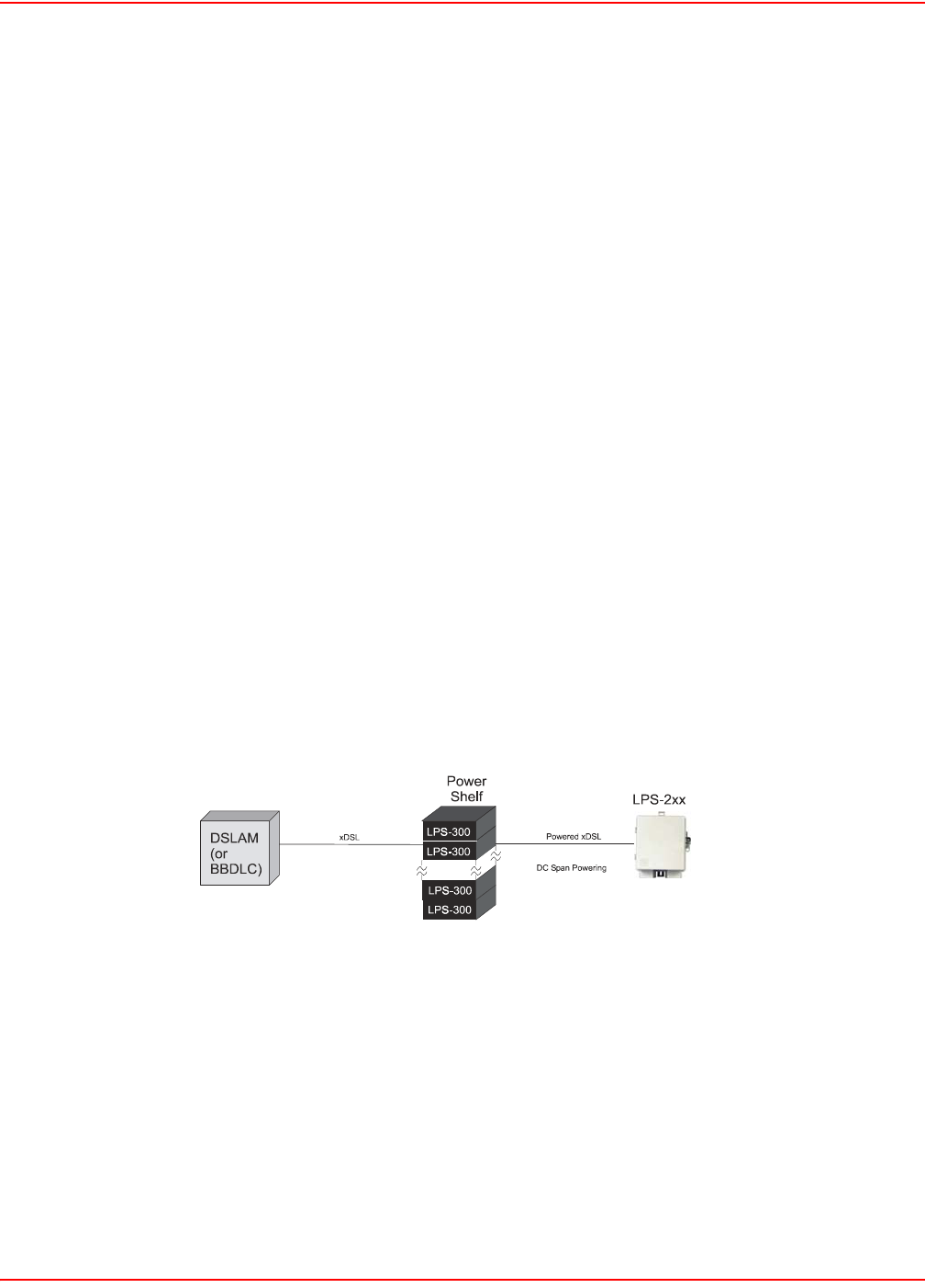
December 20, 2004 SCP-LPS20x-011-012-01H
ADC Telecommunications, Inc. 3
OVERVIEW
The LPS-20xR is an outdoor/low profile span-powered Access Point (AP). The LPS-300C Central Office (CO) power
module provides span powering to the LPS-20x. Each LPS-300 can power two individual LPS-20xs. There are
currently two types of APs available: the LPS-20xR L1A Outdoor series and the LPS-20xR L1B Low Profile series
units.
Telco carriers in the Wireless Fidelity (Wi-Fi®) market can create a carrier class access point with the following
features:
• Span powering over symmetric or asymmetric, rate adaptive Digital Subscriber Loop (DSL) from any
Digital Subscriber Line Access Multiplexer (DSLAM) supporting xDSL transport
• Hardened outdoor packaging
• Roadmap support for class Quality of Service (QoS) in the Asynchronous Transfer Mode (ATM) DSL
backhaul
• Simple Network Management Protocol (SNMP) Management Information Base (MIB), allowing integration
into their management system
• Product family support for fatter pipe, NxDS1 backhaul
• Low first-cost deployment from remote cabinet DSLAM and Digital Loop Carrier (DLC) platforms
• NEBS and OSMINE compliant
Wi-Fi deployment fits into the overall DSLAM broadband services market. It allows Telco carriers to use their
existing infrastructure to easily be part of the public Wi-Fi arena. The LPS-20x is a simple end device that, with the
exception of the span powering, uses standards based interfaces. This permits it to be deployed directly from
existing DSLAM equipment without the need to introduce new CO ATM switching elements into the Telco carrier’s
network.
The two-wire dry xDSL interface from the DSLAM is routed through a power shelf co-located in the CO (Figure 1).
The LPS-300C located in the power shelf does not regenerate the xDSL signal; rather, it superimposes a Class A2,
DC powering voltage on the outside plant (OSP) interface. This is a standard xDSL signal since it comes from a
DSLAM. Therefore, there is no proprietary signal added to the stream.
Figure 1. CO-Based DSLAM Deployment
13-LPS20xR
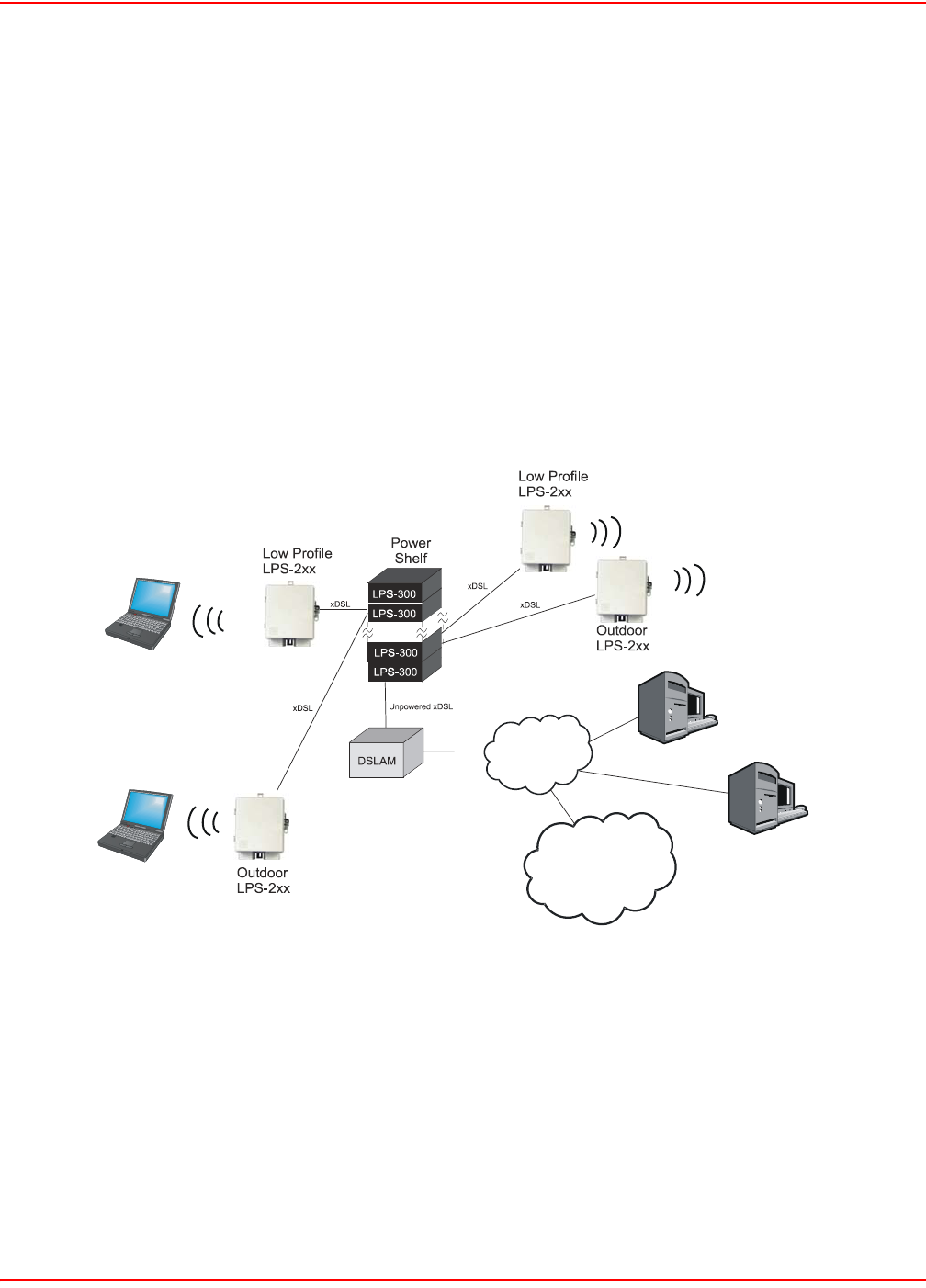
SCP-LPS20x-011-012-01H December 20, 2004
4ADC Telecommunications, Inc.
DESCRIPTION
WI-FI CO-BASED DSLAM DEPLOYMENT
Using existing DSLAMs, a G.SHDSL or ADSL pair is routed to the LPS-300C power card in the HMS-318 power
shelf (Figure 2). The LPS-300C is a 3192 double-wide card that supports two powered xDSL pairs per module. A
total of 11 LPS-300C cards can be installed in the UL-60950 compliant HMS-318 power shelf for a total of 22
span-powered pairs. The LPS-300C, without affecting the xDSL signal, adds power to the span to operate the
LPS-20x.
The access point converts the ATM data coming in on the span and bridges it an Ethernet transparent bridge
broadcasting via 802.11b Wi-Fi standards to any client who has a wireless Network Interface Card (NIC).
The Access Controller forwards to the RADIUS Server authentication requests, then the RADIUS Server
authenticates the user. Once authenticated, the user has access to the internet. The Access Server tracks the
connection time for billing purposes. Some applications may include the replacement of pay phones with LPS-20xs
to create a wireless public hotspot.
Figure 2. Wi-Fi CO-Based DSLAM Deployment
Tel c o
Customer 1
Customer 2
Access Controller/Server
Internet
14-LPS20xR1
RADIUS Server

December 20, 2004 SCP-LPS20x-011-012-01H
ADC Telecommunications, Inc. 5
G.SHDSL RATE/REACH
G.SHDSL is a symmetrical rate adaptive transport technology and ranges from 72 kb/s to 2.368 Mb/s in 64 kb/s
increments over a single twisted pair. The LPS-20x defaults to rate adaptive mode for best link speed. The range on
an unimpaired G.SHDSL cable is shown in Table 3. The G.SHDSL attenuation is less than 0.5 dB.
Table 3. G.SHDSL Reach/Rate
Cable Gauge
Reach
(kft)
Rate
(kb/s)
26 AWG 1-7 2320
8 1808
10 1048
12 656
14 464
16 336

SCP-LPS20x-011-012-01H December 20, 2004
6ADC Telecommunications, Inc.
ADSL RATE/REACH
ADSL is an asymmetrical rate adaptive transport technology and ranges from 288 kb/s to 8000 kb/s downstream
and 128 kb/s to 800 kb/s upstream. The range on an unimpaired ADSL cable (Fast Mode) is shown in Table 4 and
(Interleaved Mode) in Table 5.
Table 4. ADSL Reach/Rate - Fast Mode
Table 5. ADSL Reach/Rate - Interleaved Mode
Cable Gauge
Reach
(kft)
Rate -
Upstream
(kb/s)
Rate -
Downstream
(kb/s)
26 AWG 1-8 800 8000
10 736 5728
12 608 3200
14 450 1728
16 256 768
18 128 288
Cable Gauge
Reach
(kft)
Rate -
Upstream
(kb/s)
Rate -
Downstream
(kb/s)
26 AWG 1-8 800 8000
10 736 5728
12 608 3520
14 480 1728
16 288 768
18 128 288
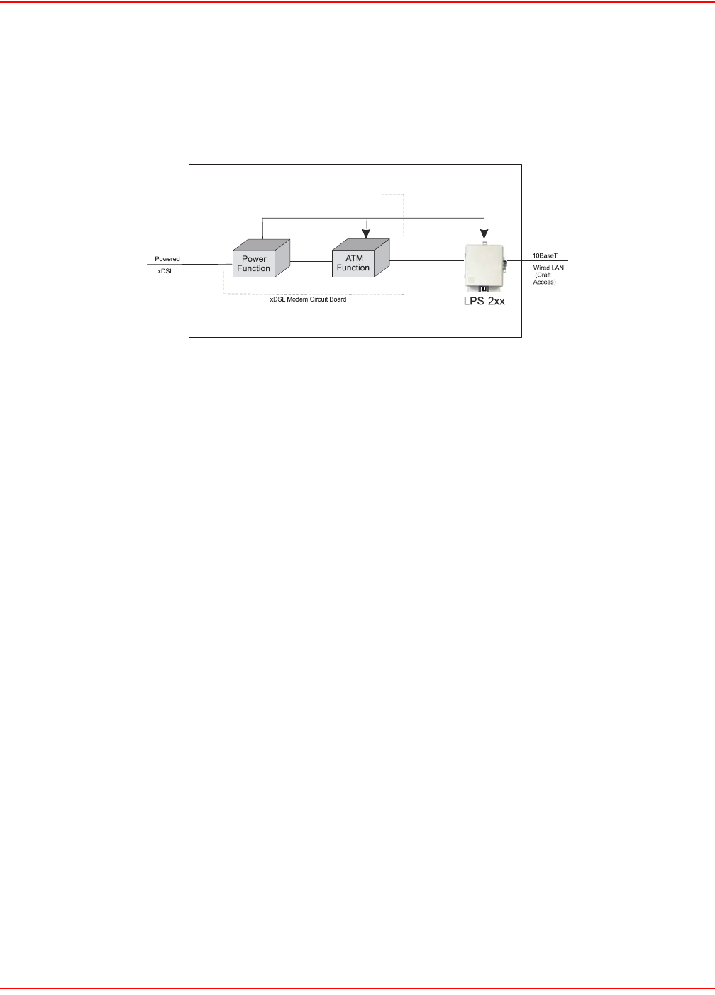
December 20, 2004 SCP-LPS20x-011-012-01H
ADC Telecommunications, Inc. 7
LPS-20X
The power function within the LPS-20x removes the line power provided by the LPS-300C and generates the DC
voltage for the LPS-20x functions (Figure 3). As shown in Figure 3, the power function is integrated with the xDSL
modem circuit board. The ATM function of the modem maps all users to a single Virtual Circuit (VC) with
Unspecified Bit Rate (UBR) services.
Figure 3. LPS-20x Functional Diagram
1
5
-LP
S
2
0
xR1

SCP-LPS20x-011-012-01H December 20, 2004
8ADC Telecommunications, Inc.
SPECIFICATIONS
Table 6 lists the specifications for the LPS-20x.
Table 6. Specifications
Category Item Value
Operational RFT Circuit Voltage ± 135 Vdc
Effective Capacitance between the tip
and ring connection points of the xDSL
conductors of the Telecommunication
Network
Effective Capacitance between the tip or
ring connection and earth of the xDSL
conductor of the Telecommunication
Network
Power Power Mode(s) Span powered (local power in future)
Power Consumption <13 W total for AP
Power-on operating voltage range ± 100 to ± 135 Vdc (nominal)
Polarity Tolerant of Tip/Ring reversals between CO
power module and AP
Voltage Class (Span Powering) NEBS Class A2
xDSL Line Attenuation < 0.5 dB
Line Code TC-PAM
Protection AP Gas tube primary with secondary protection
Environmental Temperature -4° F to +149° F
-20° C to +65° C
Humidity 5% to 95% (non-condensing)
Altitude -200 ft. MSL to 13,000 ft. MSL;
-60 m MSL to 4,000 m MSL
Compliance NEBS GR-63-CORE, Issue 2
GR-1089-CORE, Issue 3
SR-3580, Level 3
Safety UL/cUL 60950-1
UL/cUL 60950-21
EN 60950-1:2001
EN 60950-21:2003
EMC EN 300/328-2, V1.1.1:July 2000
EN 301 489-1, V1.2.1:August 2000
EN 301 489-17 V1.1.1:September 2000
EN 300 386-2 V1.1.3:December 1997

December 20, 2004 SCP-LPS20x-011-012-01H
ADC Telecommunications, Inc. 9
Connectors xDSL 1/2” terminal nuts
Wired Local Area Network (LAN)
(Craft Access)
10BaseT RJ-45 Jack
Antenna Dual spatial diversity internal, external
antennas via dual SMA female jack connectors
Mounting Two point wall or pole mount requiring no template
Category Item Value

SCP-LPS20x-011-012-01H December 20, 2004
10 ADC Telecommunications, Inc.
Physical – Low
Profile
Height 10.25 in. (26.0 cm.)
Width 8.5 in. (21.6 cm.)
Depth 3.0 in. (7.62 cm.)
Weight 4.0 lbs. (1.81 kg.)
Physical – Outdoor Height 10.25 in. (26.0 cm.)
Width 8.5 in. (21.6 cm.)
Depth 4.8 in. (12.2 cm.)
Weight 4.0 lbs. (1.81 kg.)
Category Item Value

December 20, 2004 SCP-LPS20x-011-012-01H
ADC Telecommunications, Inc. 11
SPAN-POWERED XDSL MODEM
INTERFACE - (G.SHDSL)
On the network side, the LPS-20x supports one High-Speed Digital Subscriber Line (G.SHDSL) pair. The LPS-20x
conforms to the G.SHDSL ITU-T G.991.2, Annex A and Annex B standards. However, by default, the LPS-20x
comes up in auto mode, which means it automatically detects and switches to the Annex being used on the pair.
On the client side, it supports a Local Area Network (LAN) interface that is compliant with the IEEE 802.3 (10BaseT)
standards and a Wireless Local Area Network (WLAN) interface that is compliant with IEEE 802.11b standards.
INTERFACE (ADSL)
On the network side, the LPS-20x supports one Asymmetric Digital Subscriber Line (ADSL) pair. The LPS-20x
conforms to the ADSL ITU G.992.1, G.dmt, ANSI T1.413i2, Alcatel, Alcatel 1.4, ADI standards. However, by default,
the card comes up in auto mode, which means it automatically detects and switches to the line coding type being
used on the pair.
On the client side, it supports a Local Area Network (LAN) interface that is compliant with the IEEE 802.3 (10BaseT)
standards and a Wireless Local Area Network (WLAN) interface that is compliant with IEEE 802.11b standards.

SCP-LPS20x-011-012-01H December 20, 2004
12 ADC Telecommunications, Inc.
ATM
The ATM specifications are listed in Table 7. The LPS-20x provides Unspecified Bit Rate (UBR) service on two
Virtual Circuits (VCs) – one User VC and one Management VC.
Table 7. LPS-20x ATM Requirements
Parameter Specification
UNI ATM Forum UNI Version 3.1 and 4.0
Signaling ITU-T Q.2931
ATM Adaptation Layer 5 ITU I.363.5
Cell Delineation and HEC ITU I.432
ATM Cell Format ITU I.361
Classes of Service UBR (CBR and VBR-nrt in future)
User VC 1 UBR bridge session
Management VC 1 UBR bridge session management can be
accessed.
ATM Provisioning Virtual Circuit Identifier (VCI)/Virtual Path
Identifier (VPI) are assignable
Network Management SNMP V2, RFC-1213, MIB II, RFC-1493 Bridge,
RFC-3276 G.SHDSL, IEEE 802DOT11
Standards - G.SHDSL ITU-T G.991.2, Annex A, B
Standards - ADSL ITU-T G.992.1, (ADSL G.dmt), Annex A
ITU G.992.5 (ADSL +)
ANSI T1.413 i2
ITU G.992.3 (ADSL2, G.dmt.bis) (future)

December 20, 2004 SCP-LPS20x-011-012-01H
ADC Telecommunications, Inc. 13
DSL - WIDE AREA NETWORK (WAN) SIDE
Transparent bridging is supported. The default for the management IP address is statically defined as 192.168.1.1.
ATM INTERNETWORKING REQUIREMENTS (Table 8)
Table 8. LPS-20x Internetworking Specifications
SNMP MANAGEMENT
Remote SNMP v2c is supported over all interfaces (user configurable). SNMP supports all applicable groups of the
following MIBs: RFC-1213 MIB II, RFC-1493 Bridge, RFC-3276 G.SHDSL and RFC-2662 ADSL. For a complete list
of MIBs, refer to Configuring the SNMP Interface on page 132.
HTTP MANAGEMENT
This interface is used to access and configure the LPS-20x. Access to the management screens is protected with a
simple username and password login. The web browser-based screens are accessible over the LAN, WAN or
WLAN.
Configuration changes are done via webpages served up by the LPS-20x.
Parameter Specification
Protocol RFC 1483 Bridged Ethernet over ATM
Encapsulation Logical Link Control (LLC) or VC-Mux

SCP-LPS20x-011-012-01H December 20, 2004
14 ADC Telecommunications, Inc.
SOFTWARE DOWNLOAD
GUI METHODS
There are three supported methods to download software (under Maintenance\Firmware Updates):
• upload an image from a local drive
• immediately download an image from a remote server
• periodically download an updated image from a remote server
SNMP METHOD
All variations supported by the Graphical User Interface (GUI) Method are also available via SNMP. See
COLUBRIS-MAINTENANCE-MIB for more information.
START-UP
xDSL start-up is totally transparent and requires no provisioning by the customer.
PERFORMANCE MONITORING
The LPS-20x collects xDSL performance metrics. Refer to Network|Ports|Status for more information.

December 20, 2004 SCP-LPS20x-011-012-01H
ADC Telecommunications, Inc. 15
WI-FI LPS-20X
WIRELESS INTERFACE
Refer to Table 9 for LPS-20x Wi-Fi specifications.
Table 9. LPS-20x Wi-Fi Specifications
Parameter Specification
Wireless Standard IEEE 802.11B Unlicensed ISM radio band
Frequency Band 2.4 GHz to 2.4835 MHz
Range Up to 100 meters (300 feet)
Modulation Direct Sequence Spread Spectrum (DSSS)
supporting three non-overlapping channels
(CCK, DQPSK, DBPSK)
Networking • DNS Relay
• DHCP Client
• IP Routing: Static and RIP v1 (RFC 1058),
RIP v2 (RFC 1723)
• SNMP v2c
• RADIUS Client (RFC 2865 and RFC 2866)
• ICMP (RFC 792)
• ARP (RFC 826)
• CIDR (RFC 1519)
• VLAN support (static or dynamically
assigned per user via RADIUS)
• Up to 16 simultaneous wireless networks
with distinct SSIDs/configurations
• Wireless bridging with up to 6 other units
Communication • Communicates with all Wi-Fi certified
wireless adapters
• Supports all operating systems
Security • Secure connection (SSL) to on-board web
based management tools
• Wireless forwarding between client stations
disabled by default
• Optional filters to block traffic not addressed
to the access controller
Management • Web-based management tool
• Secure local and remote management via
HTTPS
• Remote Syslog
• Web-based firmware upgrades
• Real-time status and information protocol
traces
Interfaces • 10BaseT port used for craft access
Media Access Protocol CSMA/CA with ACK

SCP-LPS20x-011-012-01H December 20, 2004
16 ADC Telecommunications, Inc.
IP ADDRESS
The default for management IP address assignment is provisioned statically.
OUTPUT POWER AND RANGE
The radio output power is software controlled and can be set to 23, (20 dBm - Europe) 17 and 13 dBm. Free air
distances of 100 m can be expected when set to 23 dBm. The range varies depending on the power output. Refer to
Overview on page 3 and to Introduction to the Wireless Access Point on page 29 for more information.
Data Rate 11 Mb/s with fallback to 5.5, 2 and 1 Mb/s
Transmit Power 23 dBm (200 mW)*
20 dBm (100 mW) (Europe)
17 dBm (50 mW)
13 dBm (20 mW)
Antennas Dual internal antennas for receive path spatial
diversity with support for external antennas
Number of Clients 254
Global Market Requirements Complies with R&TTE Directive, EN 300-328-2
V1.2.1, EN 301 489-1, EN301 486-17
* Used in North America only. All others are 100 mW maximum (refer to Table 1 on page 1 and
Table 2 on page 2).
Parameter Specification

December 20, 2004 SCP-LPS20x-011-012-01H
ADC Telecommunications, Inc. 17
ANTENNA
The enclosure supports dual internal dipole antennas for diversity (Table 10). The LPS-20x always transmits on one
antenna. However, dual antennas allow diversity in the receive direction. Spatial diversity in the receive path
improves overall system performance by switching from one antenna to the other and selecting the antenna offering
the best receive signal. The access point electronics makes this selection. You have the option to attach one or two
external antennas via dual SMA connectors. One antenna is always used for transmission and reception. Therefore,
for single external antenna installations, make sure that the antenna intended as the transmit/receive antenna is
connected to the SMA connector labeled XMIT/RECEIVE.
Table 10. Antenna Specifications
Parameter Specification
Frequency 2.4 to 2.5 GHz
VSWR 2.0:1
Peak Gain 2 to 3 dBi
Radiation Pattern Omni-directional
Polarization Vertical or Horizontal

SCP-LPS20x-011-012-01H December 20, 2004
18 ADC Telecommunications, Inc.

December 20, 2004 SCP-LPS20x-011-012-01H
ADC Telecommunications, Inc. 19
INSTALLATION AND TEST
The LPS-20xR can be mounted to either a wall or pole.
To ensure the safety of personnel and equipment, observe the following safety rules:
FOR EQUIPMENT USING AN RFT CIRCUIT
At the time of installation, a system assessment must be carried out to ensure that the effective capacitance of the
total system, including the capacitance if the AP does not exceed 400 µf line to earth and 13 µf line to line.
At the time of installation, you must ensure that the voltage rating of the wiring of the AP is adequate for the normal
RFT circuit voltage along with superimposed transients and that the circuits to be connected together are either all
RFT-C circuits or all RFT-V circuits.
Required Tools
• (2) #10 x 1-1/2” wood screws
• (2) #10 x 1” anchors
• (2) #10 flat washers
• 1/4-inch flat-head screwdriver
• No. 1 Phillips screwdriver
• 216 Tool (can wrench) or 3/8” insulated nut driver
• 5/32-inch hex key, drilled for tamper-proof fasteners
• insulated-handle wire stripper
• insulated-handle needlenose pliers
• insulated-handle wire cutter
PREPARING THE UNIT
DANGER Always treat the xDSL pair as if it were live with high voltage present. Follow local practice when
installing a xDSL pair because voltages up to ±135 Vdc may be present.
All wiring external to this product should conform to local wiring codes and practices.
ATTENTION
STATIC SENSITIVE DEVICE – DO NOT HANDLE ANY MATERIAL WITHOUT FIRST TAKING
PROPER STATIC CONTROL PRECAUTIONS.
WARNING Maintain a minimum distance of 20 cm when operating this device to avoid RF Exposure.
Step Action
1 The xDSL wiring is threaded through the left rubber grommet at the bottom of the unit.
2 Use a knife to slice a small cross or “x” between the four small round punchouts in the left rubber
grommet.
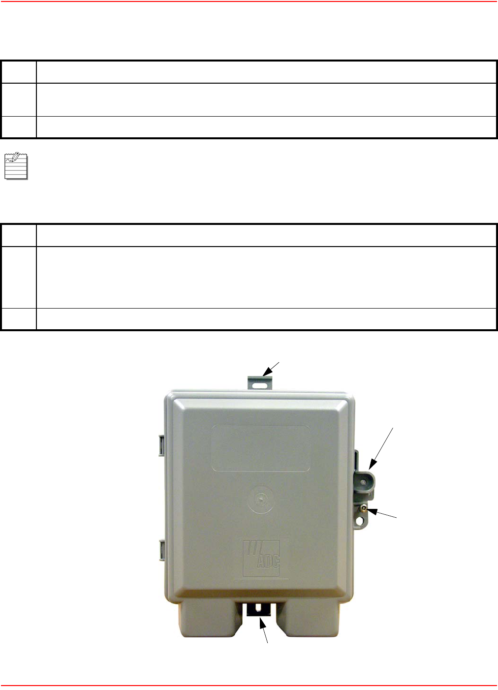
SCP-LPS20x-011-012-01H December 20, 2004
20 ADC Telecommunications, Inc.
MOUNTING THE UNIT
OPEN THE UNIT
Figure 4. Main Access Door
Step Action
1 Use the two No. 10 x 1.5-inch wood screws and flat washers provided in the Mounting Kit to attach the
unit to the side of the wall or pole (Figure 4).
2 For mounting on stucco or other similar surfaces, use the two No. 10 x 1-inch anchors from the kit.
Mount the unit as shown in Figure 4, with all access openings facing down. Refer to Table 6 on page 8 for
dimensions.
Step Action
1 You have full access to the interior of the unit by loosening the tamper proof screw from the front cover
(Figure 4).
The tamper proof screw requires a 5/32-inch drilled hex key. The tamper proof screw is preferred for
improved security.
2 Push in the main access latch and open the cover.
Mounting Hole
Mounting Hole
Main Access Latch
12A-LPS20xR1
Tamper Proof
Screw
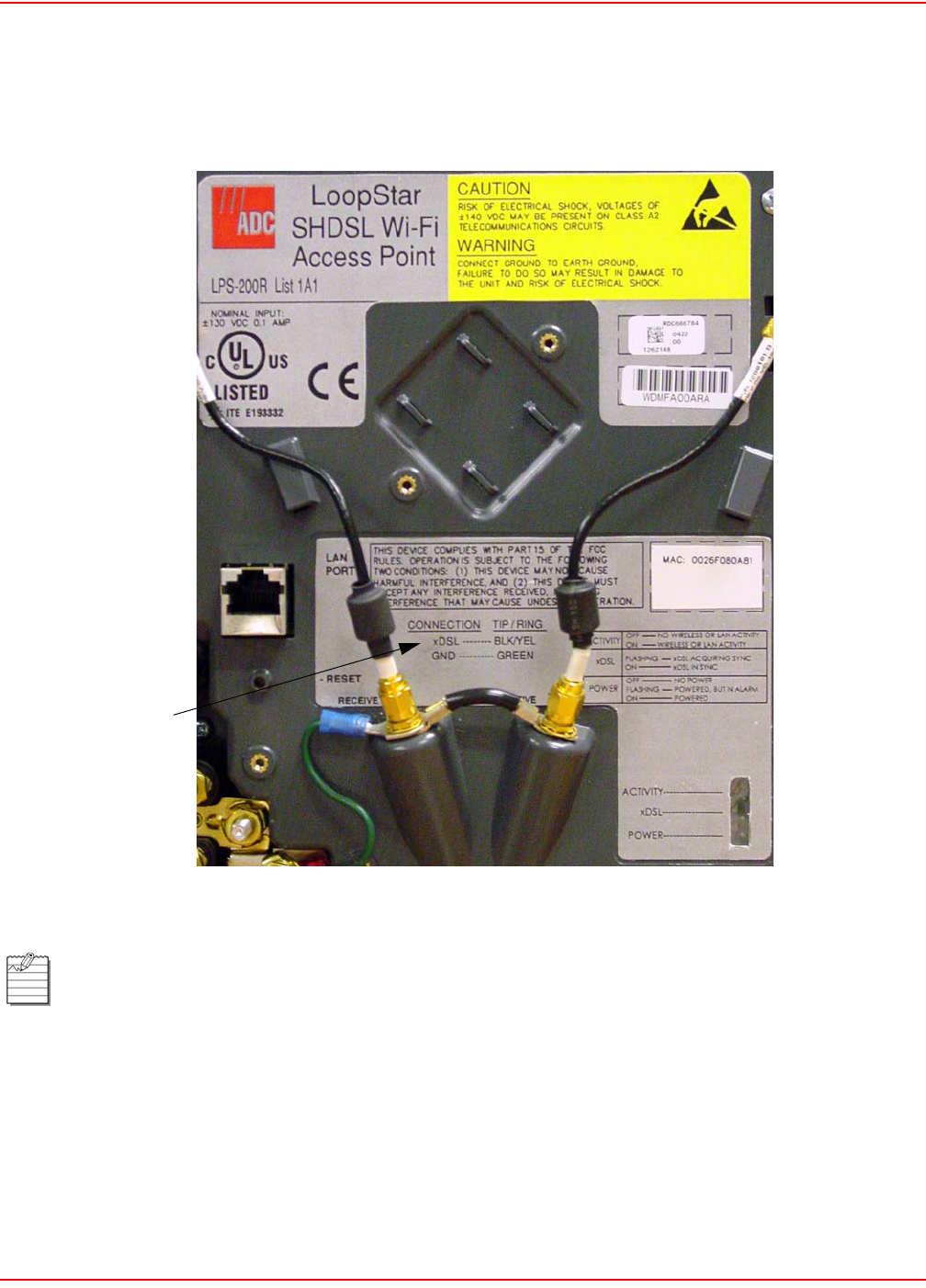
December 20, 2004 SCP-LPS20x-011-012-01H
ADC Telecommunications, Inc. 21
REFERENCE LABELS
During installation, refer to the Reference labels (Figure 5) affixed on the electronics cover. The bottom label (middle
section of the Reference Label) identifies the Ground and xDSL Tip and Ring wires.
Figure 5. Reference Labels
The reference labels for the following models will look similar to the ones above:
LPS-200R L1B(x) (G.SHDSL)
LPS-202R L1A(x) (ADSL)
LPS-202R L1B(x) (ADSL)
30-LPS20xR1
Ground and xDSL
Tip and Ring wires

SCP-LPS20x-011-012-01H December 20, 2004
22 ADC Telecommunications, Inc.
ATTACH THE GROUND WIRE
ATTACH THE XDSL TIP AND RING WIRES
WARNING The ground termination on the unit is also used for the primary gas-tube protectors for the xDSL
circuit.
Use #10 AWG wire to ensure a good ground connection to the unit.
Step Action
1 Route the ground wire through the bottom left rubber grommet of the unit (Figure 6 on page 23).
A 10 AWG (25.8 mm) solid copper ground wire is recommended.
2 Use a 216 tool to loosen the nut and the top two washers from the ground lug.
3 Loop the ground wire around the ground lug.
4 Tighten the nut with a 216 tool.
5 Connect the other end of the ground wire to a suitable ground termination point such as a ground rod,
following local practice.
DANGER Always treat the xDSL pair as if it were live with high voltage present. Review the safety
precautions at the beginning of this section before preceeding.
To avoid electrical shock, handle the stripped xDSL wire by its insulation with insulated-
handled needlenose pliers.
Step Action
1 Route the service cable through the bottom left rubber grommet of the unit (Figure 6 on page 23).
2 Use a 216 tool to loosen the nuts on the xDSL tip and ring termination posts in the unit.
3 Prepare the xDSL tip and ring conductors in the service cable using insulated wire strippers.
4 Use insulated needle nose pliers to loop the tip and ring conductors around the xDSL tip and ring
termination posts between the first and second washers.
5 Tighten both nuts with a 216 tool.
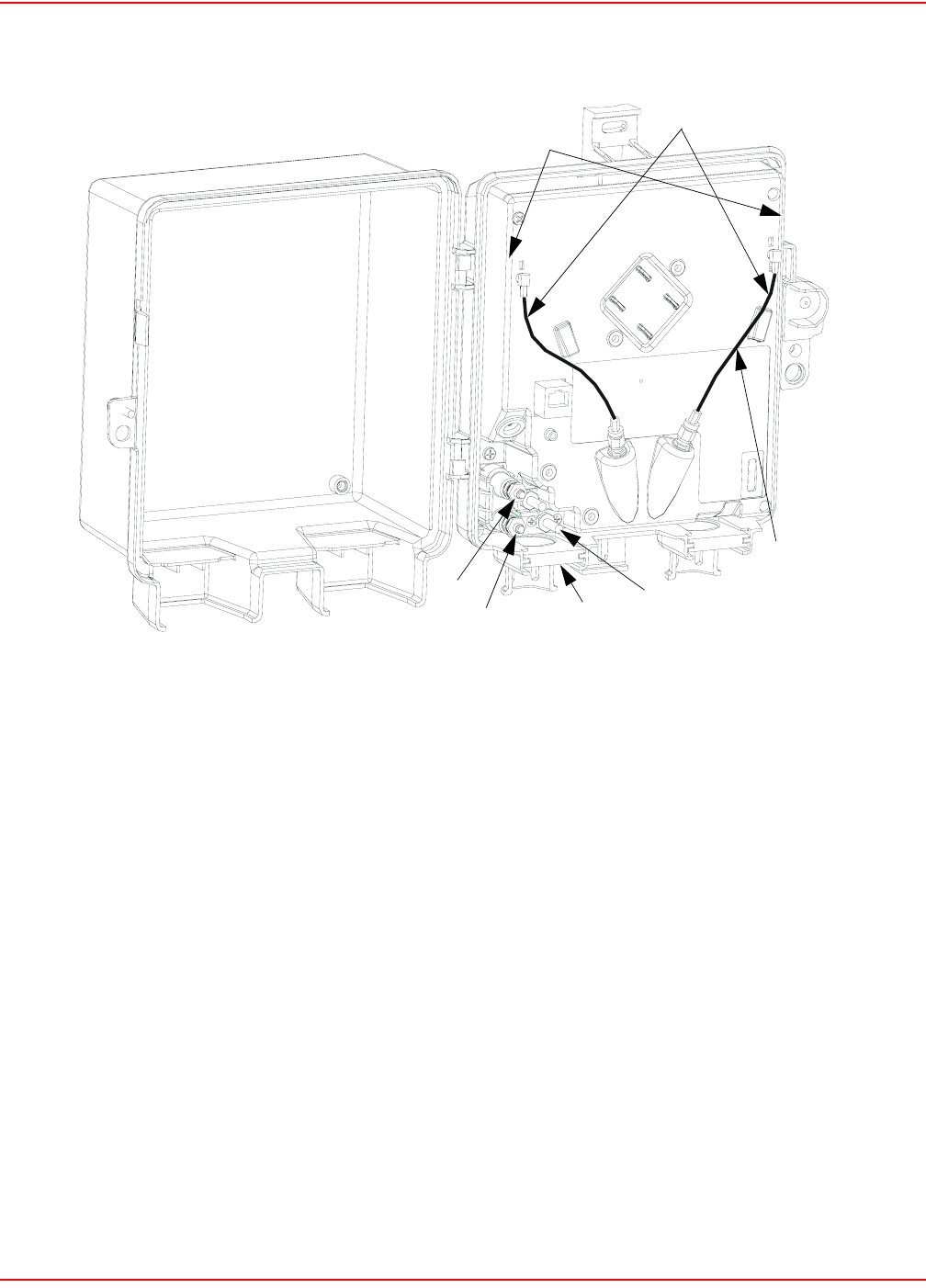
December 20, 2004 SCP-LPS20x-011-012-01H
ADC Telecommunications, Inc. 23
Figure 6. Attach Frame-Ground Wire and xDSL Tip and Ring Wires,
Disconnect Right Internal Antenna
xDSL Ring
xDSL Tip Left Rubber
Internal Antenna Leads
20A-LPS20xR1
Grommet
Ground Lug
Internal Antennas
Behind Cover
Remove XMIT/RECEIVE
Cable

SCP-LPS20x-011-012-01H December 20, 2004
24 ADC Telecommunications, Inc.
USING EXTERNAL ANTENNA(S)
Typical single external antenna applications use only the XMIT/RECEIVE antenna connection. The second antenna
connection can be used when receive diversity is desired with dual external antennas.
ATTACH EXTERNAL N-TYPE SINGLE ANTENNA (OPTIONAL)
The receive-only internal antenna (left cable) should be removed when directional radiation patterns are
required for the external antenna application. Consult your appropriate engineering guide.
The external antenna mounting kit is an optional item that can be purchased from ADC
(LPS-299 L1). This kit is used when you are connecting an external antenna that has an N-Type connector.
Refer to Product Support on page 177. If the unit is not opened, refer to Open the Unit on page 20.
Step Action
1 Disconnect the right internal antenna (XMIT/RECEIVE) cable connections on both ends (Figure 6 on
page 23). Store in a safe place for later use. The left internal antenna (receive only) cable should be left
attached (refer to Note above for exception).
2 Remove the right rubber grommet at the bottom of the unit (Figure 7 on page 25).
3 Use a knife to slice a small cross or “x” between the four small round punchouts in the rubber grommet.
4 Route the external antenna lead end connector through the grommet and pull the cable assembly up
into the middle of the unit.
5 Seat the rubber grommet into the right grommet slot at the bottom of the unit (Figure 7 on page 25).
6 Connect the N-Type external antenna connector to the LPS-299 L1 SMA to N-Type adapter assembly
(Figure 7 on page 25).
7 Screw the SMA connector of the adapter assembly to the right side SMA connector of the LPS-20x
(Figure 7 on page 25).
8 Tie wrap connectors to the electronics cover with those supplied in the mounting kit.
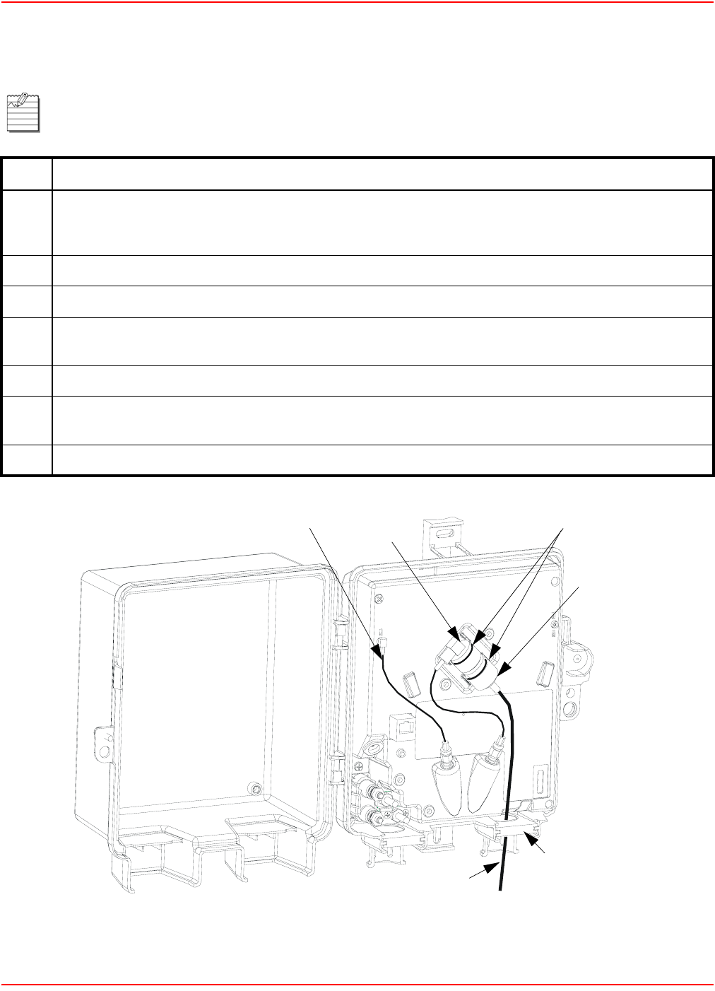
December 20, 2004 SCP-LPS20x-011-012-01H
ADC Telecommunications, Inc. 25
ATTACH EXTERNAL SMA-TYPE ANTENNA (OPTIONAL)
Figure 7. Attach N-Type and SMA-Type Single External Antennas
The external antenna mounting kit is an optional kit that can be purchased from ADC
(LPS-299 L1). This kit is used when you are connecting an SMA-Type external antenna only. Refer to
Product Support on page 177. If the unit is not opened, refer to Open the Unit on page 20.
Step Action
1 Disconnect the right internal antenna (XMIT/RECEIVE) cable connections on both ends (Figure 6 on
page 23). Store in a safe place for later use. The left internal antenna (receive only) cable should be left
attached. (Refer to Note under Using External Antenna(s) on page 24 for exception).
2 Remove the right rubber grommet at the bottom of the unit (Figure 7 on page 25).
3 Use a knife to slice a small cross or “x” between the four small round punchouts in the rubber grommet.
4 Route the external antenna lead end connector through the grommet and pull the cable assembly up
into the middle of the unit.
5 Seat the rubber grommet into the right grommet slot at the bottom of the unit (Figure 7 on page 25).
6 Screw the SMA connector of the external antenna to the right side SMA connector of the LPS-20x
(Figure 7 on page 25).
7 Tie wrap connectors to the electronics cover with those supplied in the mounting kit.
External Antenna Lead
Type N Connector
SMA to N-Type
Adapter Assembly
Right Rubber Grommet
Tie Wraps
Internal Antenna
21A-LPS20xR1
Lead

SCP-LPS20x-011-012-01H December 20, 2004
26 ADC Telecommunications, Inc.
SYSTEM STATUS WINDOW AND LEDS
The electronics enclosure has a System Status window through which Status LEDs can be viewed. The Status
LEDs indicate different system states. The top portion of the reference label provides a guide to what the Status
LEDs indicate (Figure 8).
Figure 8. System Status Window
ACTIVITY
ON WIRELESS OR LAN ACTIVITY
xDSL IN SYNC
NO POWER
xDSL ACQUIRING SYNC
POWERED
POWERED, BUT IN ALARM
POWER
xDSL
ON
OFF
FLASHING
ON
FLASHING
NO WIRELESS OR LAN ACTIVITY
OFF
POWER---------------------
xDSL---------------------
ACTIVITY---------------------
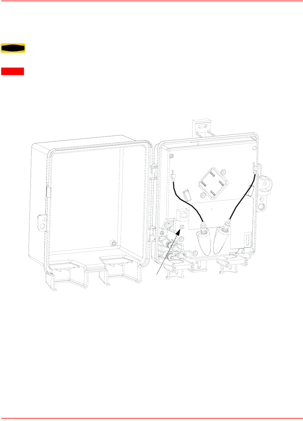
December 20, 2004 SCP-LPS20x-011-012-01H
ADC Telecommunications, Inc. 27
RESET BUTTON
The reset button is located on the lower left side of the inside of the LPS-20x (Figure 9). Use the end of a paper clip
or another pointed object to press the button.
Figure 9. Reset Button
WARNING Do not press the reset button for more than 5 seconds. Doing so will cause the LPS-20x to revert
to the factory defaults.
CAUTION Resetting the LPS-20x deletes all your configuration settings, resets the Administrator username
and password to ‘admin’ , and sets the Wireless port and LAN port IP address to 192.168.1.1.
The management tool can also be used to restart or reset the LPS-20x.
Reset
20A-LPS20xR1
Button

SCP-LPS20x-011-012-01H December 20, 2004
28 ADC Telecommunications, Inc.
RESTARTING
Press and release the button from 1 to <5 seconds to restart the LPS-20x. This is equivalent to cycling the power.
The LPS-20x will restart immediately.
RESETTING TO FACTORY DEFAULTS
To reset the LPS-20x to its factory default settings, do the following:
CLOSE THE UNIT
To close the unit:
WARNING Do not press the reset button for more than 5 seconds. Doing so will cause the LPS-20x to revert
to the factory defaults.
Restarting will drop all active connections.
CAUTION Resetting the LPS-20x deletes all your configuration settings, resets the Administrator username
and password to ‘admin’ , and sets the Wireless port and LAN port IP address to 192.168.1.1.
The management tool can also be used to restart or reset the LPS-20x.
Step Action
1 Press and hold the reset button for more than 5 seconds. All the lights on the LPS-20x front panel will
light up.
2 When the lights begin to flash (after about five seconds), release the button.
3 The LPS-20x will restart with factory default settings. When the xDSL LED stops flashing, the LPS-20x
is fully operational.
Failure to close the access door leaves the interior exposed to the environment. This shortens the life span
of the components.
Step Action
1 Close the front cover.
2 Tighten the tamper proof screw on the front cover until it is completely seated.
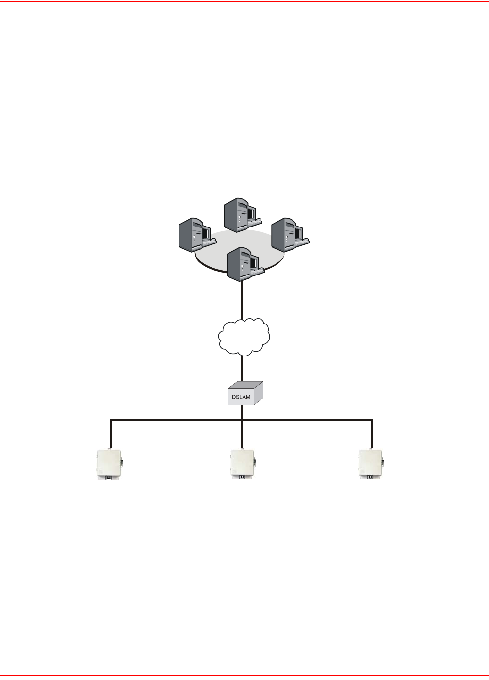
December 20, 2004 SCP-LPS20x-011-012-01H
ADC Telecommunications, Inc. 29
INTRODUCTION TO THE WIRELESS ACCESS POINT
The LPS-20x wireless Access Point (AP) series are remote units that are designed to work in conjunction with
Remote Authenication Dial-In User Service (RADIUS) Servers, access controllers or similar products (Figure 10).
The role of the LPS-20x is to extend the wireless network and provide intelligent data forwarding to maintain the
security of the network.
The LPS-20xs are interconnected using a backbone LAN or are daisy-chained together. This makes it easy to add
more wireless coverage to service additional floor space or an increasing number of users.
Figure 10. LPS-20x
The LPS-20x provides wireless network coverage in a radius of up to 100 meters (300 feet). It uses radio waves in
the 2.4 Ghz band to communicate with client stations. To maintain the security of individual client stations on the
wireless network, the LPS-20x does not forward data between wireless client stations by default.
INTELLIGENT BRIDGE
Unlike a traditional bridge which automatically forwards all traffic between ports, the LPS-20x can apply security
filters to maintain the security of the network. When enabled, these filters essentially block all traffic that is not
addressed to or received from the access controller.
01-LPS21xR1
LPS-20x LPS-20x LPS-20
x
Internet
Secure tunnels protected
by IPSec or PPTP
RADIUS
server
VPN
server
Management
station
Network Operations Center
Access
Controller
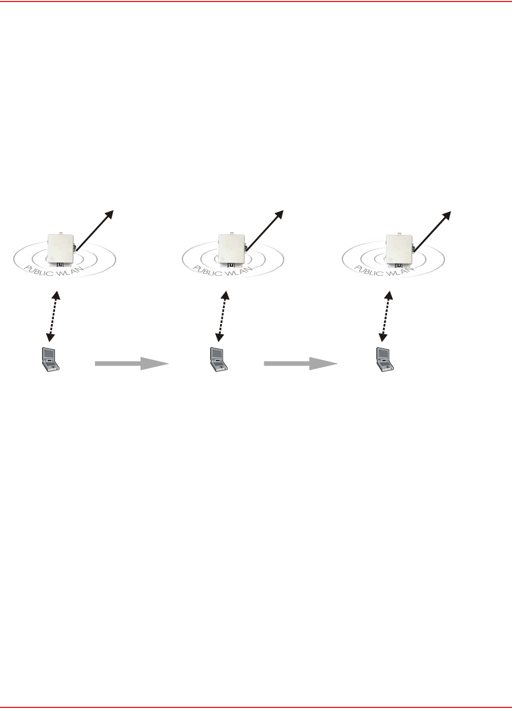
SCP-LPS20x-011-012-01H December 20, 2004
30 ADC Telecommunications, Inc.
SERVICE SENSOR
The service sensor enables the LPS-20x to determine if access to the network or a particular server is available. If
not, the LPS-20x automatically shuts off its radio transmitter taking down the wireless cell. The service sensor polls
the target device approximately every half second. For more details, refer to Service Sensor on page 94.
ROAMING
Client computers are able to move between wireless cells (called roaming) without losing contact with the network
(Figure 11). This is possible because the wireless network adapters in the client computers automatically switch to
the best available device. Authentication and billing (if used) are maintained. Figure 11 shows roaming across
several LPS-20xs.
Figure 11. Roaming
MAC-LEVEL FILTERING
When enabled, this option enables you to control access to the wireless network based on the MAC address of
client stations. You can either block access or allow access depending on your requirements.
LOCATION-AWARE AUTHENTICATION
This feature enables you to control logins to the public access network based on the wireless access point a
customer is connected to. This feature works when you use the LPS-20x in conjunction with an LPS-21x or a
Colubris access controller (e.g., CN3000) that also supports the Location-Aware Authentication. If you enable this
option, when a customer attempts to login to the public access network, the access controller sets the Called-
Station-ID in the RADIUS access request to the MAC address of the wireless port the customer is associated with.
Server-side code can be written to manage access based on this information.
LPS-20x
LPS-20x LPS-20x
Client moves Client moves
connection automatically switches connection automatically switches
02-LPS20xR1
t
o
access
con
t
ro
ll
er
t
o
access
con
t
ro
ll
er to access controlle
r
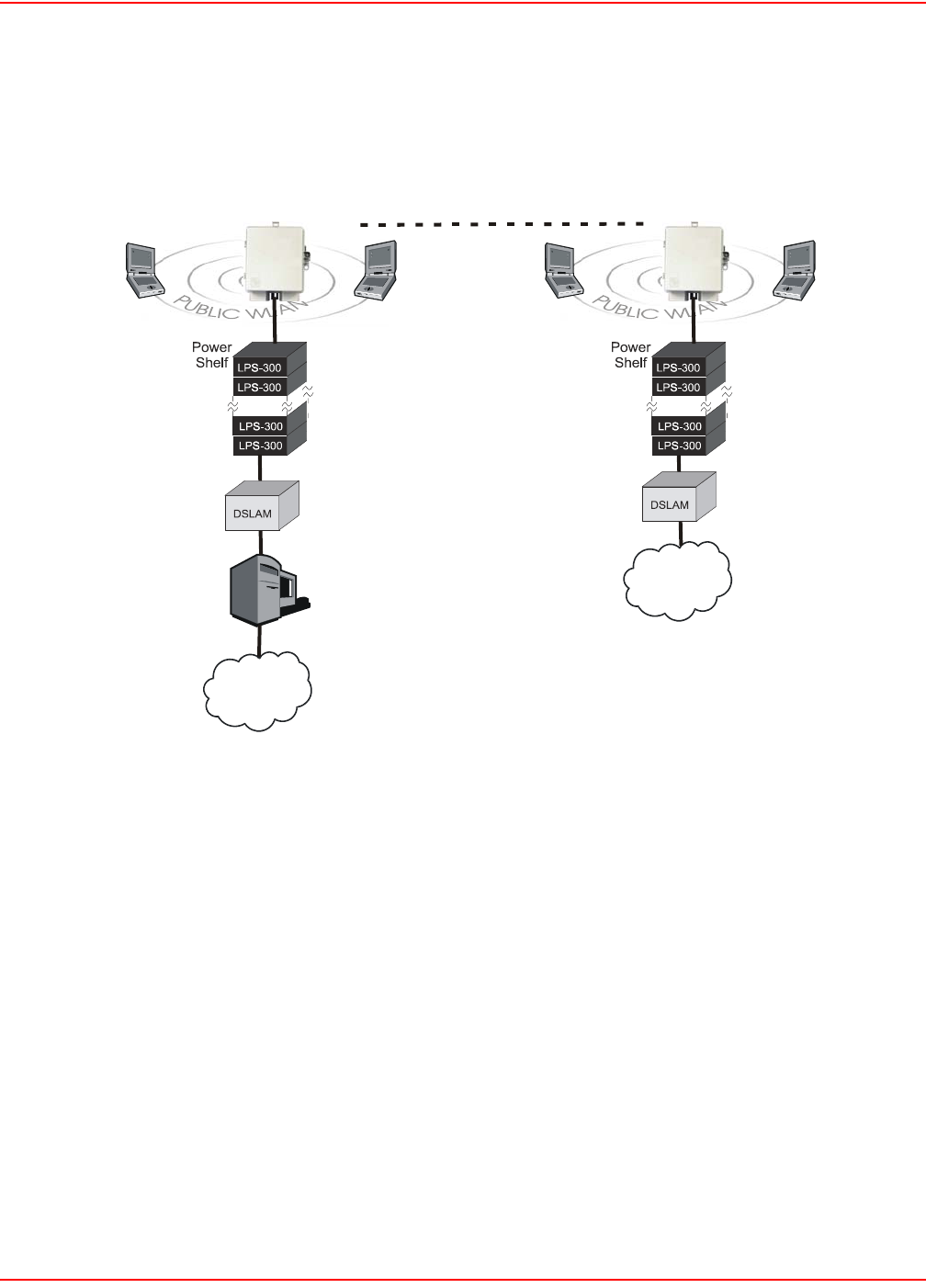
December 20, 2004 SCP-LPS20x-011-012-01H
ADC Telecommunications, Inc. 31
WIRELESS BRIDGING
The LPS-20x wireless bridging feature enables you to use the wireless radio to create point-to-point wireless links
with other access points (Figure 12). This feature can be used to extend the reach of a network without additional
wiring.
Figure 12. Wireless Bridging
Wireless bridge
Access
Controller
LP
S
-2
0
x
24-LPS20xR1
LAN
LP
S
-2
0
x
Internet
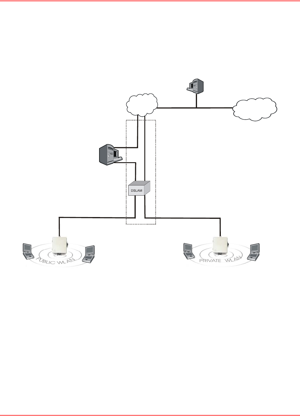
SCP-LPS20x-011-012-01H December 20, 2004
32 ADC Telecommunications, Inc.
MULTIPLE SSID AND VLAN SUPPORT
The LPS-20x provides support for multiple Service Set Identifiers (SSIDs) (Figure 13). This allows the wireless
network to be segmented into multiple distinct entities, each with its own SSID. This feature is very useful when
combined with Virtual Local Area Network (VLAN) support. For example, in this scenario public and private users
share the same infrastructure with complete security.
Figure 13. Multiple SSID amd VLAN Support
The wireless network is split into two WLANs: public and private:
• The Public WLAN maps authentication traffic between the LPS-20x and the Access Controller on VLAN
60. Once a user is authenticated, traffic to the Internet does not use a VLAN.
• The Private WLAN maps authentication traffic between the LPS-20x and the RADIUS Server on VLAN
70. Once a user is authenticated, traffic to the Internet or Corporate Intranet is mapped across VLANs 51,
52, 53.
2
5
-LP
S
2
0
xR1
LPS-20x LPS-20x
Access
Controller
Internet Corporate
Intranet
RADIUS Server
VLAN 60
A
uthentication VLAN 70
Traffic VLAN 51, 52, 53
VLAN 70, 51, 52, 53
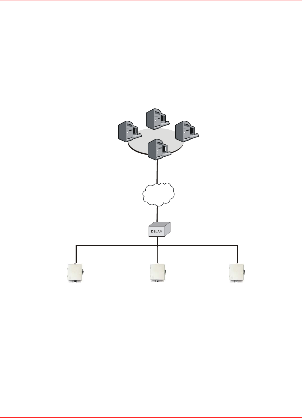
December 20, 2004 SCP-LPS20x-011-012-01H
ADC Telecommunications, Inc. 33
PLANNING YOUR INSTALLATION
OVERVIEW
The LPS-20x enables you to extend the coverage of a public access network. One or more LPS-20xs can be
installed in conjunction with an access controller (Figure 14).
Figure 14. Access Controller
ACCESS CONTROLLER
The access controller provides user authentication and accounting support for the wireless customers and manages
the security of the network. This means ensuring that only authorized traffic is permitted to reach the protected
network resources. If connected to the Internet, its integrated firewall provides protection from hackers.
01-LPS21xR1
LPS-20x LPS-20x LPS-20
x
Internet
Secure tunnels protected
by IPSec or PPTP
RADIUS
server
VPN
server
Management
station
Network Operations Center
Access
Controller

SCP-LPS20x-011-012-01H December 20, 2004
34 ADC Telecommunications, Inc.
LPS-20X
The LPS-20x (and the access controller) provide wireless network coverage in a radius of up to 100 meters
(300 feet). This is called a wireless cell. To maximize coverage of the cell, the LPS-20x is best installed in an open
area with as few obstructions as possible. Try to choose a location that is central to the area being served.
The LPS-20x uses radio waves in the 2.4 Ghz band to communicate with client stations. Radio waves cannot
penetrate metal, instead they are reflected. This means that the LPS-20x is able to transmit through wood or plaster
walls, and closed windows. However, the steel reinforcing found in concrete walls and floors may block
transmissions or reduce signal quality by creating reflections. This can make it difficult for a single LPS-20x to serve
users on different floors in a concrete building. Such installations will require a separate LPS-20x on each floor.
Client computers are able to move between cells (called roaming) without loosing contact with the network. This is
possible because wireless adapters automatically switch to the best available LPS-20x.
INSTALLATION STEPS
1. Install the LPS-20x (Installation and Test on page 19).
2. Establish a connection to the management tool (Management Tool on page 35).
3. Define management tool security settings (Management Tool Security on page 46).
4. Configure and deploy the wireless network (Configuration – Setting up the Wireless LAN on page 62).
5. Configure the connection to the access controller
(Configuring the Connection to the Access Controller on page 79).
6. Configure the service sensor (optional) (Service Sensor on page 94).
7. Configure MAC-level filtering (optional) (MAC-Level Filtering on page 96).
8. Configure location-aware authentication (optional) (Location-Aware Authentication on page 97).

December 20, 2004 SCP-LPS20x-011-012-01H
ADC Telecommunications, Inc. 35
MANAGEMENT TOOL
The management tool is a Web-based interface to the LPS-20x that provides easy access to all configuration
functions via WLAN, LAN, or Internet Port.
MANAGEMENT STATION
The management station is the computer that you will use to connect to the management tool. To act as a
management station, a computer must:
• have a JavaScript-enabled Web browser installed (Netscape 7.1 or higher, or Internet Explorer 6.0 or
higher)
• be able to establish an IP connection with the LPS-20x
Although there are several ways to manage the LPS-20x after installation (see Management scenarios below), the
first time you configure the LPS-20x you should do so from a computer equipped with a wireless LAN card. If it is
impossible to install a wireless LAN card in your computer, you can use a computer equipped with an Ethernet card
instead. This requires a cross-over Ethernet cable.
CONFIGURING THE MANAGEMENT STATION FOR WIRELESS ACCESS
Install and configure the wireless adapter in the management station according to the directions that came with it.
During installation make sure that:
• encryption is disabled
• TCP/IP is installed and configured. The IP address of the wireless station must be on the same subnet as
the access point.
• Set the SSID to be “ADC”.
CONFIGURING THE MANAGEMENT STATION FOR WIRED ACCESS
Install and configure a network adapter in the management station according to the directions that came with it.
During installation make sure that TCP/IP is installed and configured.
!
IMPORTANT Only one administrator can be logged into the management tool at a given time. If a second
administrator logs in while the first is connected, the first administrator may be logged out
depending on system configuration (refer to Management|Management Tool|Login override).
A static IP address must be used when configuring the LPS-20x for the first time. Refer to Connecting to
the LPS-20x for the First Time on page 37.

SCP-LPS20x-011-012-01H December 20, 2004
36 ADC Telecommunications, Inc.
MANAGEMENT SCENARIOS
The LPS-20x can be managed both locally and remotely for complete flexibility. The following management
scenarios are supported:
LOCAL MANAGEMENT
• A computer connected to the wireless AP via a wireless network card.
• A computer directly connected to the LAN port on the LPS-20x. A cross-over Ethernet cable is required.
• A computer on the wired LAN that is connected to the LPS-20x.
REMOTE MANAGEMENT
Remote management of the LPS-20x is possible. For more details, refer to Configuring Remote Management
Support on page 51.
WIRELESS PORT
• IP address: 192.168.1.1 (bridged with the other ports)
• Wireless network name: ADC
• Operating frequency: Channel 10
• ESSID broadcast: On
• Relay between wireless station: Off
• Security: None
UPSTREAM PORT
• IP address: 192.168.1.1 (bridged with the other ports)
DOWNSTREAM PORT
• IP address: 192.168.1.1 (bridged with the other ports)
• Firewall: High security
MANAGEMENT TOOL
• Allow access via LAN port and downstream port
• Login name: admin
• Password: admin
!
IMPORTANT When the intelligent bridge function is enabled, wireless stations can only communicate with the
LPS-20x they are directly connected to. Managing other LPS-20xs is not possible. For more
details, refer to Intelligent Bridge on page 80.

December 20, 2004 SCP-LPS20x-011-012-01H
ADC Telecommunications, Inc. 37
CONNECTING TO THE LPS-20X FOR THE FIRST TIME
Your LPS-20x is factory configured with a static IP address assignment. The address is 192.168.1.1. In order to
connect to the LPS-20x, a computer with a WLAN or LAN NIC card is required.
It is recommended that you access the LPS-20x via a wireless connection. However, you may also connect via the
wired LAN port located on the electronics enclosure.
ASSUMPTIONS
It is assumed that the LPS-20x has already been installed and wired to the xDSL as noted in section Installation and
Test on page 19. You cannot perform any configuration on this device until power has been applied.
SETUP
1. Configure your computer with the following static IP address: 192.168.1.2. This puts your computer on the
same logical network segment as the LPS-20x. This is required so that you can gain access to the manage-
ment tool.
2. Establish a wireless connection with the LPS-20x or connect the wired LAN connector on the LPS-20x to
your computer using a cross-over Ethernet cable.
3. You are now ready to start the management tool and configure the LPS-20x.
AP STATIC IP CONFIGURATION
Please refer to Setting a Static IP Address on page 84 if you are going to install this access point into your network
with a static IP address.
AP DHCP CONFIGURATION
Please refer to Network Port Configuration on page 81 if you are going to install this access point into your network
as a DHCP client.
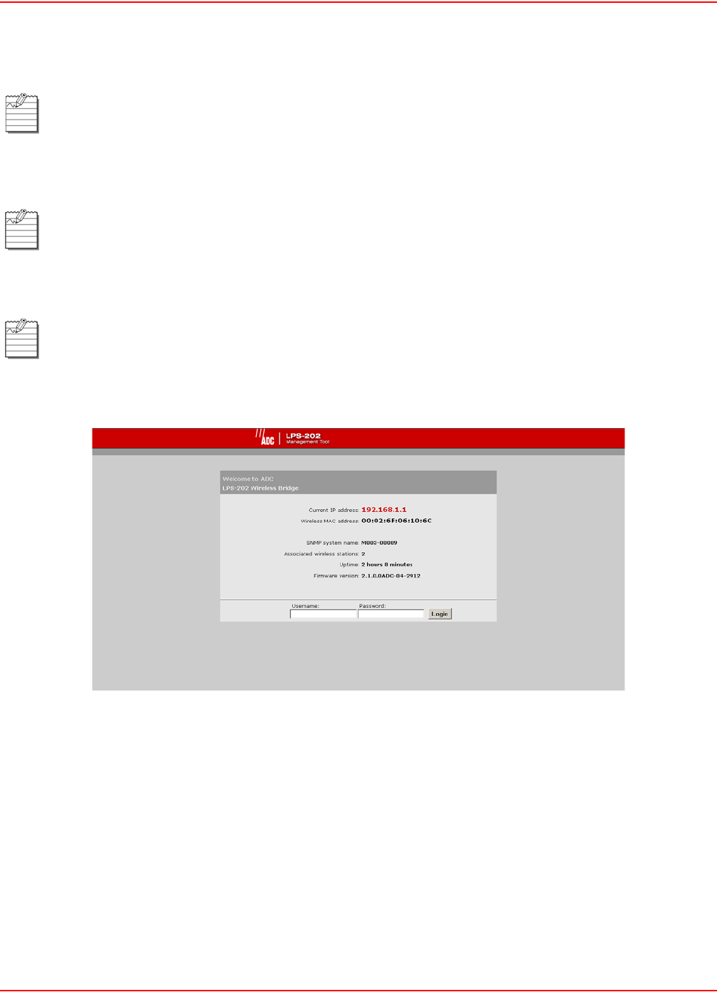
SCP-LPS20x-011-012-01H December 20, 2004
38 ADC Telecommunications, Inc.
STARTING THE MANAGEMENT TOOL
1. Start your Web browser.
2. In the address box, specify: HTTPS://192.168.1.1.
3. Press Enter. You will be prompted to accept an ADC security certificate. Do so to continue. To eliminate
this warning message, you can install your own certificate as described in SSL Certificates on page 139.
4. After you accept the ADC certificate, the management tool login page opens. By default, the username is
set to admin and the password is set to admin.
Most of the screens in this software section were captured using the LPS-202. However, the content of
screens remain the same for all LPS-20x (unless otherwise noted).
Make sure that you specify HTTPS and not HTTP.
To safeguard the security of the LPS-20x, access to the management tool must occur via a secure
connection. Before this connection can be established, you must accept an ADC security certificate. The
procedure for accepting the certificate varies depending on the browser you are using.
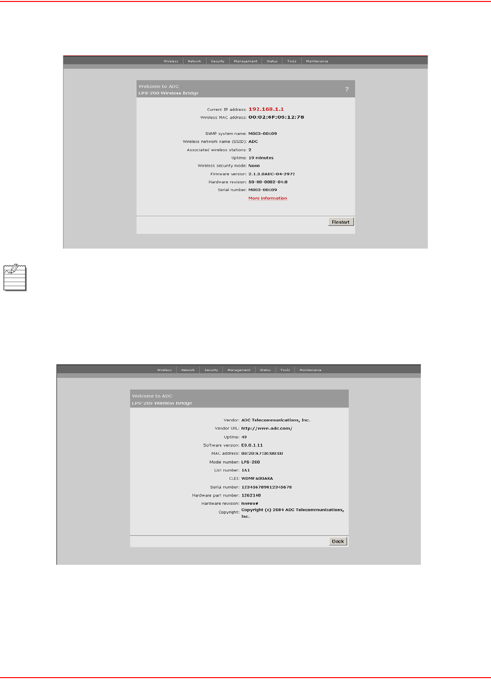
December 20, 2004 SCP-LPS20x-011-012-01H
ADC Telecommunications, Inc. 39
5. You will see the home page after you have successfully logged into the system.
6. For more information about the LPS-20x, click on More information. The following screen appears.
If this is the first time the AP has been powered up from the factory, a pop-up window will appear asking
you to change your password.
It is highly recommended that you change your password at this time.
You may also change your password under Management|Management Tool.

SCP-LPS20x-011-012-01H December 20, 2004
40 ADC Telecommunications, Inc.
HOME PAGE PARAMETERS
The LPS-20x does not require day-to-day management for successful, efficient operation.The most you will want to
do is inquire about status and statistics.
CURRENT IP ADDRESS
This is the IP assigned to all ports of the LPS-20x.
WIRELESS MAC ADDRESS
This is the MAC address associated with the LPS-20x.
SNMP SYSTEM NAME
Identifies the LPS-20x on your network. To set this, go to Management|SNMP.
WIRELESS NETWORK NAME (SSID)
Identifies the wireless network. Each client that wants to connect to the LPS-20x must use this name (unless the
broadcast WLAN name option is enabled, in which case no name needs to be specified on the client station).To set
this value, go to the Wireless>Wi-Fi page.
UP TIME
Indicates the amount of time that has passed since the LPS-20x was powered on or reset.
WIRELESS SECURITY MODE
Inidcates the protocol being used to secure the wireless network. By default, this is set to None.
FIRMWARE VERSION
Indicates the version number of the firmware currently loaded on the LPS-20x. To upgrade the firmware, go to the
Maintenance>Firmware>Updates page.
HARDWARE REVISION
Indicates the version number of the LPS-20x hardware.
SERIAL NUMBER
Indicates the serial number of the LPS-20x hardware.
LOGOUT
Click this button to log out. If you do not log out, the LPS-20x continues to maintain your connection as active until it
times out (after 10 minutes of inactivity).
The SSID is case-sensitive.

December 20, 2004 SCP-LPS20x-011-012-01H
ADC Telecommunications, Inc. 41
RESTART
Click on this button to restart the LPS-20x. It may take up to 60 seconds for the LPS-20x to become fully operational
again. When the DSL light stops flashing, the LPS-20x is fully operational. Resetting does not affect your
configuration.
Restarting will drop all active connections.

SCP-LPS20x-011-012-01H December 20, 2004
42 ADC Telecommunications, Inc.
MAIN MENU TREE
Figure 15 shows the main menu tree of the management tool.
Figure 15. Management Tool Main Menu Tree
Wireless
Wi-Fi
WLAN Profiles
Overview
Wireless Links
Neighborhood
Network
Address Allocation
Bandwidth Control
RADIUS
Security
Certificates
Access Controller
MAC Filtering
Network
Address Allocation
Bandwidth Control
Ports
Management
SNMP
System Time
Management Tool
Network
Bandwidth Control
Ports
DNS
Network
Bandwidth Control
Ports
DNS
Network
Bandwidth Control
Ports
DNS
Network
Bandwidth Control
Ports
DNS
Network
Address Allocation
Bandwidth Control
Ports
Network
Address Allocation
Bandwidth Control
Ports
Network
Address Allocation
Bandwidth Control
Ports
Status
Bridge
Ports
Wireless
Network
Bandwidth Control
Ports
IP Routes
DNS
Tools
System Tools
System Log
IP Trace
Ping
Network
Address Allocation
Bandwidth Control
Ports
Maintenance
Firmware Updates
System Info
Config File Management
23-LPS20XR1
VLAN

December 20, 2004 SCP-LPS20x-011-012-01H
ADC Telecommunications, Inc. 43
MAIN MENU TREE PARAMETERS
The following information is a brief overview of the management tool menu options. For detailed information on each
option and its parameters, consult the online help, which is available by clicking the help icon [?] that appears in the
top right corner of most boxes.
HOME
Displays basic status information on the operation of the LPS-20x. For a description of the information on the Home
page, refer to Home Page Parameters on page 40.
WIRELESS
Displays basic status information on the operation of the wireless network. Included in this menu are:
Overview
Provides a summary of important wireless settings.
Wi-Fi
Use this page to configure the operating characteristics of the wireless network.
WLAN Profiles
Use this page to define multiple SSIDs.
Wireless Links
Use this page to define point-to-point links to other access points.
Neighborhood
Use this page to do site surveys and discover other wireless access points that are operating nearby.
MAC Filtering
This option enables you to control access to the LPS-20x based on the MAC address of client stations. You can
either block access or allow access depending on your requirements.
NETWORK
The network menu contains all the options you need to fine tune the networking operation of the LPS-20x. Included
in this menu are:
Ports
Configures the settings for the upstream, downstream and wireless ports. This is where you define the settings for
your Internet connection, your connection via a broadband modem, and your connection to a wired LAN.
Bandwidth Control
Enables you to limit the flow of data traffic through the LPS-20x by controlling the outgoing bandwidth allocated to
each port.
DNS
Enables you to set the DNS servers assigned to the LPS-20x.

SCP-LPS20x-011-012-01H December 20, 2004
44 ADC Telecommunications, Inc.
SECURITY
The security menu lets you define all security-related settings. Included in this menu are:
RADIUS
This is where you define the settings the LPS-20x uses to communicate with external RADIUS servers.
Certificates
Use this option to manage the SSL certificates used by the LPS-20x.
Access Controller
This is where you specify the address of the access controller the LPS-20x will communicate with and enable the
service sensor and location-aware authentication features.
MANAGEMENT
The management menu enables you to configure the operation of the management tool and its SNMP
implementation. Included in this menu are:
Management Tool
Use this page to set the admin name and password and define security parameters that control access to the
management tool.
SNMP
Configures SNMP properties and security settings.
System Time
Configures system time.
STATUS
Use this option to view the status of the various components on the LPS-20x.
Wireless
Operational status of the LPS-20x.
Bridge
Current status of the bridge.
Ports
Determines the status of the upstream and downstream ports.
VLAN
Determines the status of the virtual LAN.

December 20, 2004 SCP-LPS20x-011-012-01H
ADC Telecommunications, Inc. 45
TOOLS
Provides diagnostic tools that can be used to investigate anomalies. Generally, you will use these only under the
direction of ADC. These tools also enable you to view the system log. The system log contains a record of all
significant events that occur on the LPS-20x. This information is useful when troubleshooting the LPS-20x with the
assistance of ADC. If needed, the system log can be configured to forward entries to a remote syslog server on the
LAN or via the Internet.
System Log
System log includes date, time, level, process and message.
System Tools
Runs different tools (e.g., interface information).
IP Trace
Trace upstream/downstream port.
Ping
Ping an IP address.
MAINTENANCE
Lets you manage configuration and firmware files and save system information for troubleshooting purposes.
Configuration File Management
Manual and automated updates of the configuration file.
Firmware Updates
Allows for manual and automated updates of the firmware file.
System Information
Save system information to your computer’s hard drive (using download command). After downloading, you restart
the LPS-20x (using restart command).
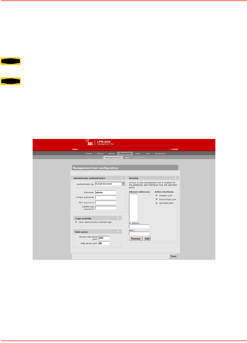
SCP-LPS20x-011-012-01H December 20, 2004
46 ADC Telecommunications, Inc.
MANAGEMENT TOOL SECURITY
The management tool is protected by the following security features.
ADMINISTRATOR PASSWORD
Access to the LPS-20x management tool is protected by a username and password to safeguard configuration
settings. The factory default setting for username is admin and password is admin. It is strongly recommended that
you change both.
To change the username and/or password, do the following:
1. On the main menu, click Management. The Management tool configuration page opens.
2. In the Administrator authentication box, enter the new username, current password, the new password,
and then repeat the new password for confirmation.
3. Click Save when you are done.
WARNING Failure to change the user name and password will leave your network at an increased risk of
attack.
WARNING If you forget the administrator password, the only way to gain access to the management tool is
to reset the LPS-20x to factory default settings (refer to Resetting to Factory Defaults on page 28).

December 20, 2004 SCP-LPS20x-011-012-01H
ADC Telecommunications, Inc. 47
ADMINISTRATOR AUTHENTICATION PARAMETERS
Authentication Via
Choose how the administrator’s username and password are verified. You can choose to store this information on
the LPS-20x (local account) or remotely on a RADIUS Server. Using a RADIUS Server enables you to have multiple
administrators, each with a unique name and password. To use a RADIUS Server, you must define a RADIUS
profile in Security>RADIUS.
Username
Login name for the administrator. The default login is “admin”.
Current Password
Current administrator password. New passwords must be at least six characters long and contain at least four
different characters. The default password is “password#1”.
New Password
Specify the new administrator password.
Confirm New Password
Retype the new administrator password.
LOGIN OVERRIDE
Allow administrator override login
When this option is enabled, an active administrator’s session will be terminated by the login of another
administrator. This prevents the management tool from being locked by an idle session until the timeout expires.
WEB SERVER PARAMETERS
Secure Web Server Port
Specify the port number the LPS-20x will use to provide secure access to the managment tool (HTTPS). By default,
this parameter is set to port 443.
Web Server Port
Specify the port number the LPS-20x will use to provide standard HTTP access to the management tool. HTTP
connections made to this port are met with a warning and the browser is redirected to the secure web server port. By
default, this parameter is set to port 80.
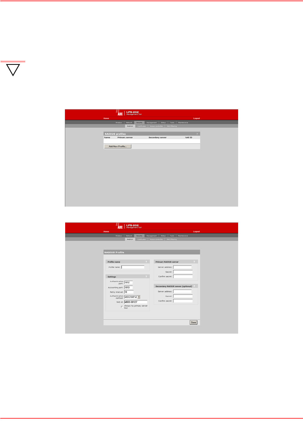
SCP-LPS20x-011-012-01H December 20, 2004
48 ADC Telecommunications, Inc.
VALIDATING ADMINISTRATOR LOGINS USING A RADIUS SERVER
You can use a RADIUS server to authenticate logins to the management tool. One advantage of this is that it
enables you to create several administrator accounts, each with its own username and password.
To setup RADIUS authentication, do the following:
1. On the main menu, click Security then click RADIUS. The Radius profiles page opens.
2. Click Add New Profile. The Add Radius profiles page opens.
3. Define the settings for the RADIUS profile you want to use to validate administrator logins. Either use an
existing profile or add a new one.
4. Click Save.
5. On the main menu, click Management. The Management tool configuration page opens.
6. In the Administrator authentication box, select the RADIUS server you defined in Step 2.
7. Click Save.
!
IMPORTANT Make sure that the RADIUS profile you select is configured and that the administrator account is
defined on a functioning RADIUS server. If not, you will not be able to log back into the LPS-20x
because the administrator password cannot be authenticated.
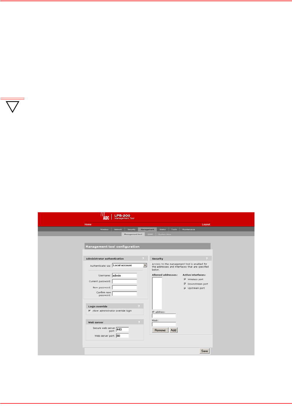
December 20, 2004 SCP-LPS20x-011-012-01H
ADC Telecommunications, Inc. 49
CONNECTION SECURITY
To maintain the integrity of the configuration settings, only one user can be connected to the management tool at a
given time. To prevent the management tool from being locked up by an idle user, two mechanisms are in place:
• If a user’s connection to the management tool remains idle for more than ten minutes, the LPS-20x auto-
matically logs the user out.
• If a second user connects to the management tool and logs in with the correct username and password,
the first user’s session may be terminated depending on system configuration. Refer to Manage-
ment|Management Tool|Login override.
HTTPS
Communications between the management station and the LPS-20x occurs via HTTPS. Before logging into the
management tool, users must accept an ADC certificate. You can replace this certificate with your own. For more
information, refer to SSL Certificates on page 139.
SECURITY SETTINGS
The LPS-20x can be managed both locally and remotely for complete flexibility. Management occurs via the Web-
based management tool which resides on the LPS-20x. For details, refer to Management Scenarios on page 36.
To Configure Security Options
1. On the main menu, click Management. The Management tool configuration page opens.
2. In the Security box, enable the management options you require. The options are described in the section
that follows.
3. Click Save.
!
IMPORTANT If you do not log out, the LPS-20x continues to maintain your connection as active until it times
out (after 10 minutes of inactivity). During this period, no other user can connect to the
management tool unless Login override under Management|Management Tool is checked.

SCP-LPS20x-011-012-01H December 20, 2004
50 ADC Telecommunications, Inc.
SECURITY PARAMETERS
Allowed Addresses
Lets you define a list of IP addresses from which access to the management tool is permitted. To add an entry,
specify the IP address and appropriate mask and click Add. When the list is empty, access is permitted from any IP
address.
Active Interfaces
Choose the interfaces through which client stations will be able to access the management tool.
Upstream/Downstream
Choose this option to allow access to the management tool via the upstream or downstream ports. These options
are enabled by default.
Wireless Port
Choose this option to allow access to the management tool via the wireless port. This option is enabled by default.
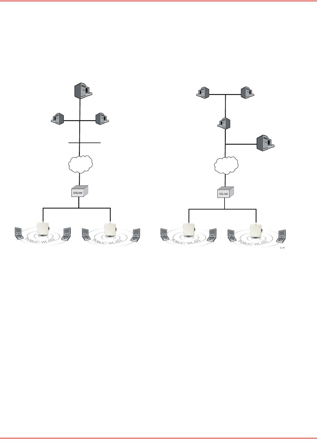
December 20, 2004 SCP-LPS20x-011-012-01H
ADC Telecommunications, Inc. 51
CONFIGURING REMOTE MANAGEMENT SUPPORT
If the LPS-20x is installed behind an access controller or RADIUS server, enabling remote access to the
management tool requires configuration settings to be defined on the access controller, RADIUS server, and the
LPS-20x. This section explains how to accomplish this for the following two scenarios (Figure 16):
Figure 16. Configuring Remote Management Support
To reach the management tool, the management stations specify the following addresses in their web browsers:
SCENARIO 1
• To reach LPS-20x A: HTTPS://192.168.10.1:5002
• To reach LPS-20x B: HTTPS://192.168.10.1:5003
SCENARIO 2
• To reach LPS-20x A: HTTPS://192.168.30.2:5002
• To reach LPS-20x B: HTTPS://192.168.30.2:5003
Static NAT mappings are used on the access controller to direct traffic to the proper LPS-20x. MAC address
authentication enables the LPS-20xs to log into the public access network. Access list definitions allow traffic to be
sent from the LPS-20xs to the management stations.
The following sections explain these configuration settings in more detail.
26-LPS20xR1
LPS-20x LPS-20x
Internet
Access
Controller
RADIUS
Server
192.168.10.0
192.168.20.0
Management
Station
20.1 20.4
192.168.1.0
S
cenario 1
LPS-20x LPS-20x
Internet
A
ccess
Controller
RADIUS
Server
30.1
Management
Station
20.2 20.3
192.168.1.0
Scenario 2
10.1
30.2
VPN Server
192.168.20.0
VPN Tunnel
20.1
30.3
ABAB

SCP-LPS20x-011-012-01H December 20, 2004
52 ADC Telecommunications, Inc.
ON THE ACCESS CONTROLLER
Create static NAT mappings
To direct management traffic to the proper LPS-20x, you need to create static NAT mappings to redirect HTTPS
traffic to the new ports you defined on the LPS-20xs.
• Map traffic on port 5002 to IP address 192.168.1.2 and port 443.
• Map traffic on port 5003 to IP address 192.168.1.3 and port 443.
ON THE RADIUS SERVER
CONFIGURE THE ACCESS CONTROLLER PROFILE
MAC address authentication
For the LPS-20x to communicate with the remote management station, it must log into the public access network.
To accomplish this, use the MAC address attribute when creating the RADIUS profile for the access controller. This
attribute enables the access controller to authenticate devices based on their MAC address. For details, see the
access controller’s administrator’s guide.
Access list
In both scenario 1 and 2, it makes sense to protect access to the RADIUS server and management station. This is
done with an access list definition that blocks all traffic to 192.168.20.0 for scenario 1, and 192.168.30.0 for scenario
2.
However, to enable the LPS-20xs and the management station to communicate, you must create an additional
access list definition as follows:
• Scenario 1: Create an access list that permits HTTPS traffic to address 192.168.20.4.
This is the IP address of the management station. For example:
access-list=LPS-20x,ACCEPT,tcp,192.168.20.4,443
• Scenario 2: The list should permit HTTPS traffic to address 192.168.30.3.
This is the IP address of the management station inside the VPN tunnel.
access-list=LPS-20x,ACCEPT,tcp,192.168.30.3,443
CREATE A LPS-20X PROFILE
Define a RADIUS profile for the LPS-20xs. The profile should activate the access list that was defined in the access
controller profile. For example:
use-access-list=LPS-20x
CREATE A USER ACCOUNT FOR EACH LPS-20X
Define a RADIUS user account for each LPS-20x. Define a unique username and password for each device.
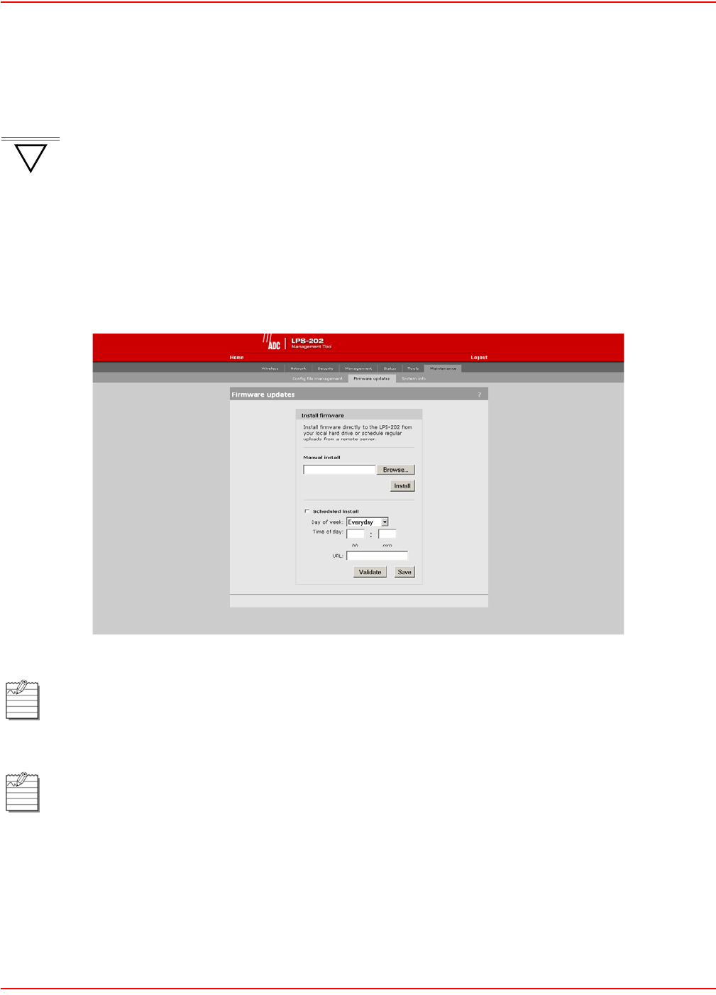
December 20, 2004 SCP-LPS20x-011-012-01H
ADC Telecommunications, Inc. 53
FIRMWARE MANAGEMENT
Firmware updates can be handled manually, automatically, or with a tool like cURL.
MANUAL UPDATE
1. On the Maintenance menu, click Firmware updates.
2. In the Install firmware box, click the Browse button and select the .cim file you just unzipped.
3. Click Install.
!
IMPORTANT When an LPS-20x is restarted, it automatically initializes itself to the default address 192.168.1.1.
If the DHCP client is enabled on the Internet port, it takes about 30 seconds after the restart for
the DHCP client to request an address. Therefore, for a short period of time after restarting, the
LPS-20x may conflict with another device on the network. This will usually not be an issue.
However, if you are using an automated tool (like cURL) to update the configuration/firmware on
several LPS-20xs at the same time, you may experience difficulties. It is recommended that you
schedule your updates to occur in succession, leaving a three minute interval between each
device.
This procedure assumes you have already loaded and unzipped the .cim file to your local hard drive.
The LPS-20x will automatically restart after the firmware has been installed. This will disconnect all client
stations. Once the LPS-20x resumes operation, all client stations will have to reconnect. Configuration
settings are preserved during firmware upgrades.

SCP-LPS20x-011-012-01H December 20, 2004
54 ADC Telecommunications, Inc.
FIRMWARE UPDATE PARAMETERS
Firmware Updates
The firmware is special software that controls the operation of the LPS-20x. Periodically, ADC will make new
versions of the firmware available.
Install Firmware
Two options are available: Manual and Scheduled.
Manual
Click the Browse button and then locate a firmware file. Select it, and then click Install to upload it to the LPS-20x.
When installation is complete, the LPS-20x will automatically restart.
Scheduled
The LPS-20x can automatically retrieve and install firmware from a local or remote URL at preset times. By placing
LPS-20x firmware on a web or ftp server, you can automate the update process for multiple units.
Click the validate button to check if the URL you specified points to a valid firmware file.
When the update process is triggered, the LPS-20x retrieves the first 2K of the firmware file to determine if it is
different than the active version. If different (older or newer version), the entire firmware file is then downloaded and
installed. This enables you to return to other firmware version, if required.
Configuration settings are preserved during the update unless stated otherwise in the release notes for the firmware.
However, all active connections will be terminated. Customers will have to log in again after the LPS-20x restarts.
All configuration settings are preserved during the update unless stated otherwise in the release notes for
the firmware.

December 20, 2004 SCP-LPS20x-011-012-01H
ADC Telecommunications, Inc. 55
Using cURL
It is possible to automate management tasks using a tool like cURL. cURL is a software client that can be used to
get/send files to/from a server using a number of different protocols (HTTP, HTTPS, FTP, GOPHER, DICT,
TELNET, LDAP or FILE).
cURL is designed to work without user interaction or any kind of interactivity. It is available for Windows and LINUX
at: http://curl.haxx.se/. You must use version 7.9.8 or higher.
The following cURL commands illustrate how to update the firmware. The following setup is assumed:
• IP address of the LPS-20x’s Internet port is 24.28.15.22.
• Management access to the Upstream port is enabled.
• Firmware is located in LPS2xx.CIM.
Login to the management interface.
curl --dump-header cookie.txt -s -m 60 "https://24.28.15.22/goform/
Logout?username=admin&pw=admin"
Prepare the LPS-20x to receive the firmware update.
curl --cookie cookie.txt -m 60 "https://24.28.15.22/script/firmware_init.asp"
Upload the firmware. Once the upload is complete, the LPS-20x will automatically restart.
curl --cookie cookie.txt -s -m 600 -F firmware=@LPS20x.cim -F backup=Install
"https://24.28.15.22/goform/ScriptUploadFirmware"
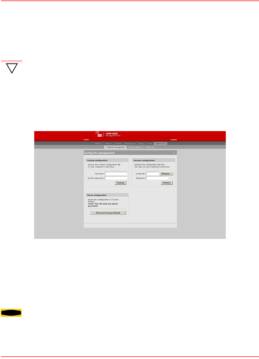
SCP-LPS20x-011-012-01H December 20, 2004
56 ADC Telecommunications, Inc.
CONFIGURATION FILE MANAGEMENT
The configuration file contains all of the settings that customize the operation of the LPS-20x.
You can save and restore the configuration file manually, automatically, or with a tool like cURL.
MANUAL UPDATES
Use the Config file management option on the Maintenance menu to manage your configuration files.
The following three options are available:
Backup Configuration File
This option enables you to backup your configuration settings so they can be easily restored in case of failure. This
option is also used when you want to directly edit the configuration file (refer to WPA Security on page 110).
Reset Configuration
Use this option to return the configuration of the LPS-20x to its factory default settings.
!
IMPORTANT When an LPS-20x is restarted, it automatically initializes itself to the current address (default is
192.168.1.1). If the DHCP client is enabled on the Internet port, it takes about 30 seconds after the
restart for the DHCP client to request an address. Therefore, for a short period of time after
restarting, the LPS-20x may conflict with another device on the network. This will usually not be
an issue. However, if you are using an automated tool (like cURL) to update the configuration/
firmware on several LPS-20xs at the same time, you may experience difficulties. It is
recommended that you schedule your updates to occur in succession, leaving a three minute
interval between each device.
WARNING Resetting to factory defaults sets the administrator password to ‘admin’ and resets all configuration
settings.

December 20, 2004 SCP-LPS20x-011-012-01H
ADC Telecommunications, Inc. 57
Restore Configuration File
Enables you to restore a configuration from a previously saved backup. This feature enables you to maintain several
configuration files with different settings, which can be useful if you frequently need to alter the configuration of the
LPS-20x or if you are managing several LPS-20xs from a central site.
USING CURL
It is possible to automate management tasks using a tool like cURL. cURL is a software client that can be used to
get/send files to/from a server using a number of different protocols (HTTP, HTTPS, FTP, GOPHER, DICT,
TELNET, LDAP or FILE).
cURL is designed to work without user interaction or any kind of interactivity. It is available for Windows and LINUX
at: http://curl.haxx.se/. You must use version 7.9.8 or higher.
The following cURL commands illustrate how to manage the configuration file. The following setup is assumed:
• IP address of the LPS-20x’s Internet port is 24.28.15.22.
• Management access to the Upstreaam port is enabled.
• Configuration file is located in LPS2xx.CFG.
Uploading the Configuration File
1. Login to the management interface.
curl --dump-header cookie.txt -s -m 60 "https://24.28.15.22/goform/
Logout?username=admin&pw=admin"
2. Prepare the LPS-20x to receive the configuration update.
curl --cookie cookie.txt -m 60 "https://24.28.15.22/script/ config_init.asp"
3. Upload the configuration file.
curl --cookie cookie.txt -s -m 600 -F config=@LPS2xx.cfg -F backup=Restore
"https://24.28.15.22/goform/ScriptUploadConfig"
4. Reset the LPS-20x to activate the new configuration.
curl --cookie cookie.txt -s -m 60 "https://24.28.15.22/script/reset.asp"
Downloading the Configuration File
1. Login to the management interface.
curl --dump-header cookie.txt -s -m 60 "https://24.28.15.22/goform/
Logout?username=admin&pw=admin"
2. Download the configuration file.
curl --cookie cookie.txt "https://24.28.15.22/download/config.cfg"
-o config.cfg
3. Logout.
curl --cookie cookie.txt -s -m 4 "https://24.28.15.22/goform/
Logout?logout=Logout"
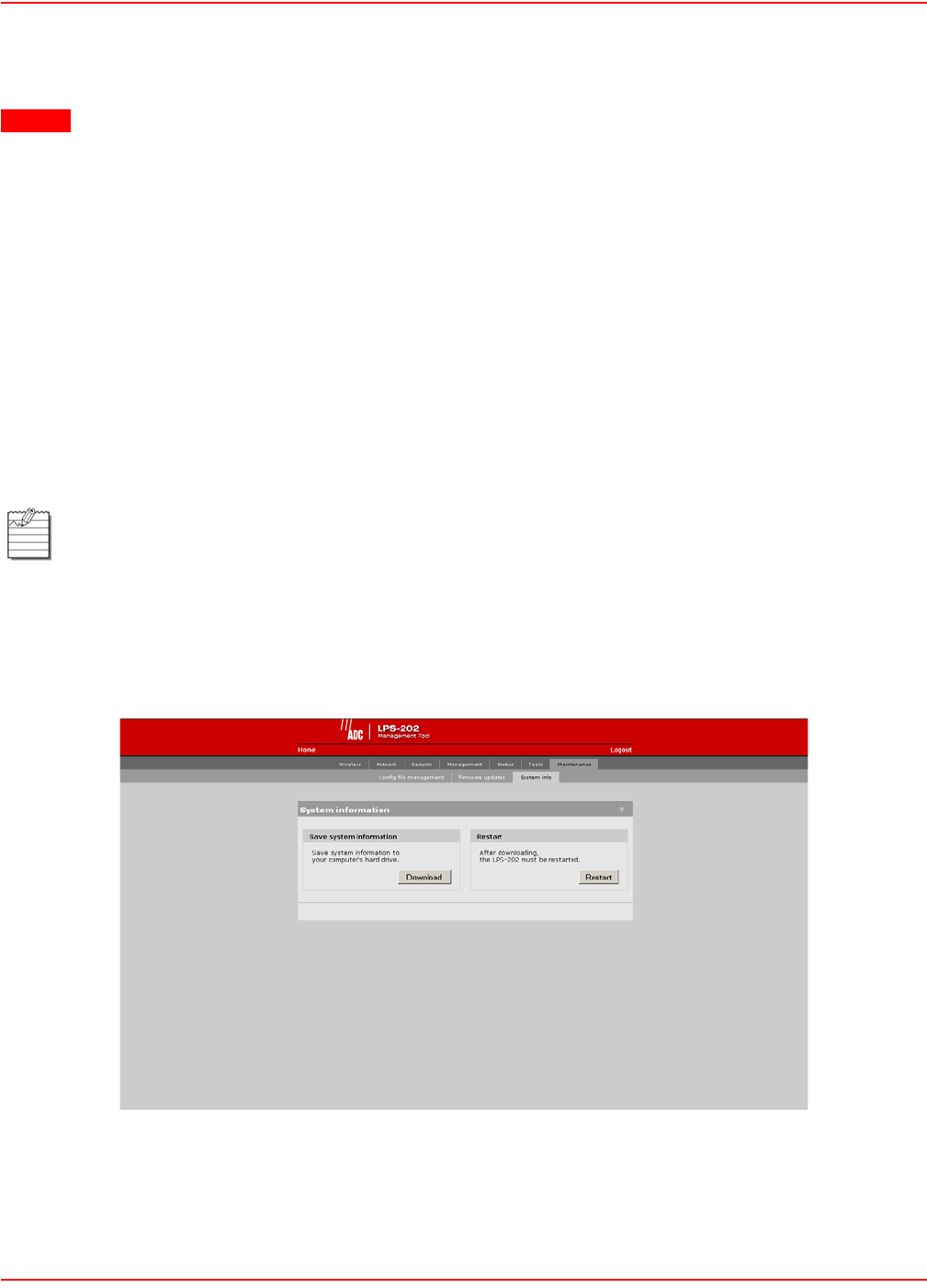
SCP-LPS20x-011-012-01H December 20, 2004
58 ADC Telecommunications, Inc.
Resetting the Configuration to Factory Defaults
1. Login to the management interface.
curl --dump-header cookie.txt -s -m 60 "https://24.28.15.22/goform/
Logout?username=admin&pw=admin"
2. Reset configuration to factory defaults.
curl --cookie cookie.txt -m 5 "https://24.28.15.22/goform/
ScriptResetFactory?reset=Reset+to+Factory+Default"
3. Reset the LPS-20x to activate the new configuration.
curl --cookie cookie.txt -s -m 60 "https://24.28.15.22/script/reset.asp"
SYSTEM INFORMATION
Use this screen to save troubleshooting information to your computer’s hard drive. The information in this file can
only be decoded by ADC. After you save system information, you must restart the LPS-20x to resume proper
operation.
1. On the Maintenance menu, click System info.
2. In the save system information box, click the Download button to save the system information to your
computer’s hard drive.
3. In the Restart box, click the Restart button. You will be asked to log back into the system (refer to Starting
the Management Tool on page 38).
CAUTION Resetting the LPS-20x deletes all your configuration settings, resets the Administrator username
and password to ‘admin’ , and sets the Wireless port and LAN port IP address to 192.168.1.1.
The management tool can also be used to restart or reset the LPS-20x.
Restarting will drop all active connections.
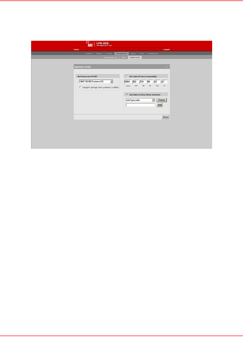
December 20, 2004 SCP-LPS20x-011-012-01H
ADC Telecommunications, Inc. 59
SYSTEM TIME
1. On Management menu, click System time. The System time configuration page opens.
SYSTEM TIME PARAMETERS
Set Time Zone and DST
Choose the time zone the LPS-20x is located in. You may also enable support for daylight savings time.
Set Date and Time (Manually)
Use this option to manually set the system date and time.
Set Date and Time (Time Server)
Choose this option to have the LPS-20x periodically contact a network time server to update its internal clock. Time
servers are checked in the order they appear in the list. Use the Add and Delete buttons to define new servers or
remove existing servers.
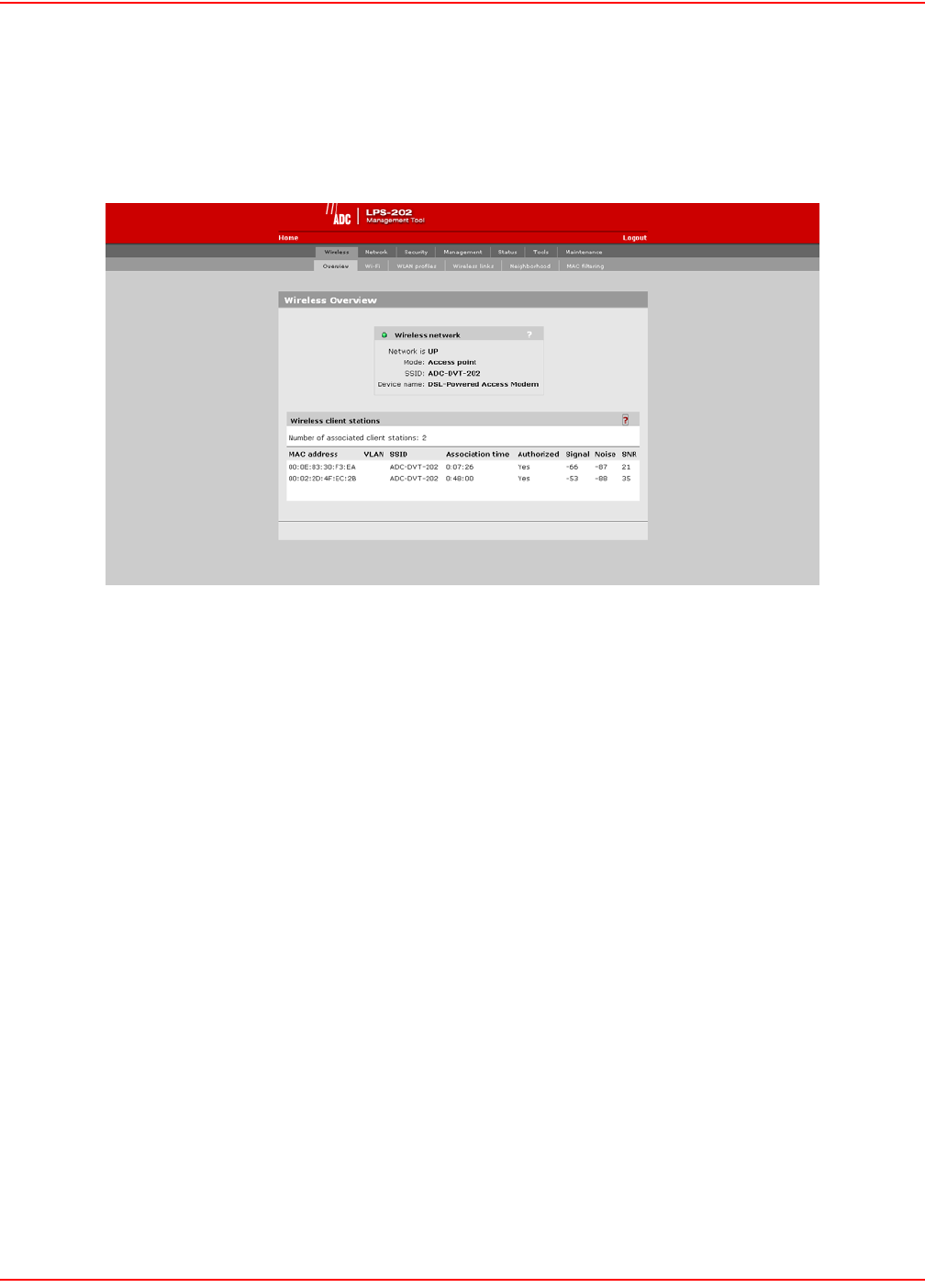
SCP-LPS20x-011-012-01H December 20, 2004
60 ADC Telecommunications, Inc.
WIRELESS OVERVIEW
Use this screen to gather information on your wireless system.
1. On the Wireless menu, click Overview.
WIRELESS NETWORK PARAMETERS
Network is up or down
Indicates the status of the wireless network.
Mode
Indicates if the LPS-20x is operating in Access Point or in Point-to-Point mode.
SSID
Name assigned to the wireless network.
Device name
The name that identifies the LPS-20x on the wireless network (for information purposes only).
WIRELESS CLIENT STATION PARAMETERS
Mac address
The Ethernet address of client station(s) that are associated to the AP.
SSID
The SSID that the client station(s) is associated with.
Association time
Indicates how long the client station has been associated with the LPS-20x.

December 20, 2004 SCP-LPS20x-011-012-01H
ADC Telecommunications, Inc. 61
Authorized
Applies to client stations using 802.1x only. A value of “Yes” indicates that 802.1x authentication was successful. A
value of “No” indicates that 802.1x authentication was unsuccessful. If 802.1x support is not enabled on the LPS-
20x, this field shows “yes”.
Signal
Indicates the strength of the radio signal received from the client stations. Signal strength is expressed in dBm. The
higher the number, the stronger the signal.
Noise
Indicates how much background noise exists in the signal path between client stations and the LPS-20x. Noise is
expressed in dBm. The lower (more negative) the value, the weaker the noise.
SNR
Indicates the relative strength of client station radio signals versus the radio interference (noise) in the radio signal
path. In most environments, SNR is a good indicator for the quality of the radio link between the client stations and
the LPS-20x. A higher SNR value means a better quality radio link.
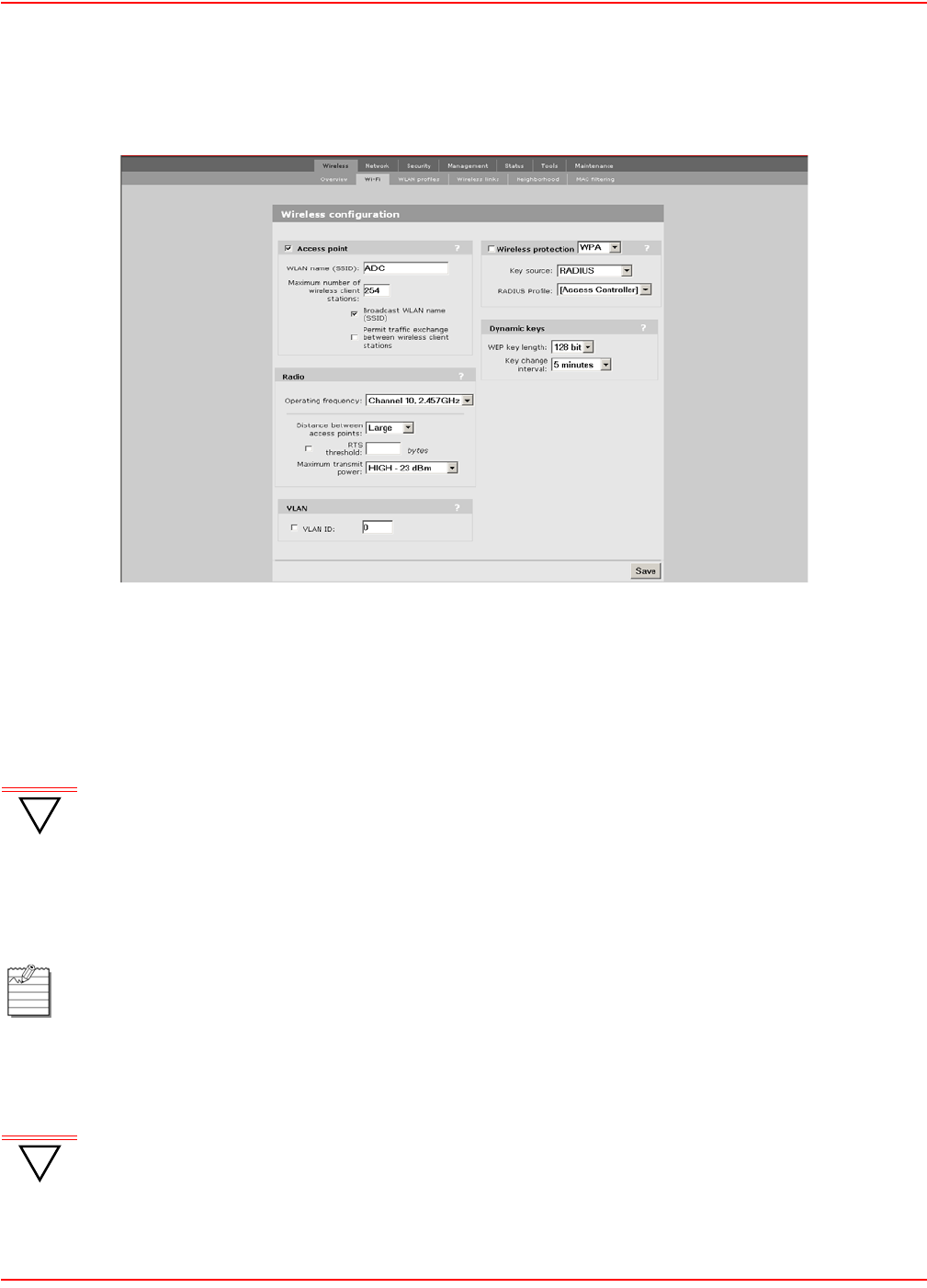
SCP-LPS20x-011-012-01H December 20, 2004
62 ADC Telecommunications, Inc.
CONFIGURATION – SETTING UP THE WIRELESS LAN
1. On the main menu, click Wireless, then click Wi-Fi. The Wireless configuration page opens.
2. Configure the parameters as described in the sections that follow.
3. Click Save when you are done.
ACCESS POINT PARAMETERS
Enable this option to activate the wireless access point (default). When this option is disabled, wireless client
stations will not be able to connect.
WLAN name (SSID)
Specify a name to uniquely identify your wireless network. Each client computer that wants to connect to the
LPS-20x must use this name.
Maximum number of wireless client stations
Specify the maximum number of wireless client stations that can be associated with this SSID at the same time.
!
IMPORTANT If you turn this feature off while provisioning the LPS-20x via a wireless connection, you will lose
communication to the device.
The name is case-sensitive.
!
IMPORTANT The total number of wireless client stations that can be connected to the LPS-20x at the same time
across all WLAN profiles is 254.

December 20, 2004 SCP-LPS20x-011-012-01H
ADC Telecommunications, Inc. 63
Broadcast WLAN name (SSID)
When this option is enabled, the LPS-20x will broadcast its wireless network name (SSID) to all client stations. Most
wireless adapter cards have a setting that enables them to automatically discover access points that broadcast their
names and automatically connect to the one with the strongest signal. If you disable this option, client stations will
have to specify the network name you enter for WLAN name when they connect.
Permit traffic exchange between wireless client stations
Enable this option to allow wireless client stations to exchange data with one another. By default, the LPS-20x
blocks all traffic between wireless client stations.
RADIO PARAMETERS
Wireless Mode
The transmission speed and frequency band is 802.11b: 11 Mbps in the 2.4 GHz frequency band.
Operating Frequency
Select the correct frequency for the LPS-20x to operate in. The frequencies that are available are determined by the
radio installed in the LPS-20x and the regulations that apply in your country.
For optimum performance when operating in 802.11b mode, choose a frequency that differs from other wireless
access points operating in neighboring cells by at least 25 MHz. Consult the Wireless > Neighborhood page to
view a list of access points currently operating in your area.
Distance Between Access Points
Use this parameter to adjust the receiver sensitivity of the LPS-20x. This parameter should only be changed if:
• you have more than one wireless access point installed in your location
• you are experiencing throughput problems
In all other cases, use the default setting of Large. If you have installed multiple LPS-20xs, reducing the receiver
sensitivity of the LPS-20x from its maximum level will help to reduce the amount of crosstalk between the wireless
stations to better support roaming clients. By reducing the receiver sensitivity, client stations will be more likely to
connect with the nearest access point.
RTS Threshold
Use this parameter to control collisions on the link that can reduce throughput. If the Status -> Wireless page
shows increasing values for Tx multiple retry frames or Tx single retry frames, you should adjust this value until
the errors clear up. Start with the largest value and slowly decrease until errors are minimized. Note that using a
small value for RTS threshold can affect throughput.
If a packet is larger than the threshold, the LPS-20x will hold it and issue a request to send (RTS) message to the
client station. Only when the client station replies with a clear to send (CTS) message will the LPS-20x send the
packet. Packets smaller than the threshold are transmitted without this handshake.
Transmit Power
Use this parameter to set the transmission power of the wireless radio.
• HIGH: Sets the maximum transmission power the wireless card is capable of. It will be either 100 mW (20
dBm) or 200 mW for North America (23 dBm).
• MEDIUM: 17 dBm
• LOW: 13 dBm

SCP-LPS20x-011-012-01H December 20, 2004
64 ADC Telecommunications, Inc.
VLAN PARAMETERS
VLAN ID
Assigns a VLAN ID to the wireless network. The LPS-20x bridges all wireless traffic to the matching VLAN
connected to the Internet port.
WIRELESS PROTECTION PARAMETERS
Select the type of protection you want to use for the wireless network.
WPA
This option enables support for users with Wi-Fi Protected Areas (WPA) client software.
Key Source
This option determines how the Temporary Key Integrity Protocol (TKIP) keys are generated.
• RADIUS: The LPS-20x obtains the Microsoft Point-to-Point Encryption (MPPE) protocol key from the
RADIUS server. This is a dynamic key that changes each time the user logs in and is authenticated. The
MPPE key is used to generate the TKIP keys that encrypt the wireless data stream. Select the appropriate
RADIUS server.
• Preshared Key: The LPS-20x uses the key you specify in the Key field to generate the TKIP keys that
encrypt the wireless data stream. Since this is a static key, it is not as secure as the RADIUS option.
Specify a key that is between 8 and 64 characters in length. It is recommended that the preshared key be
at least 20 characters long, and be a mix of letters and numbers.
Key/Confirm key
Specify a key that is between 8 and 64 characters in length.
!
IMPORTANT Enabling this feature bypasses all security features that are active on the LPS-20x. Make sure that
your VLAN has the appropriate security installed to protect access to the network.

December 20, 2004 SCP-LPS20x-011-012-01H
ADC Telecommunications, Inc. 65
802.1x
This option enables support for users with 802.1x client software. The LPS-20x supports 802.1x client software that
uses EAP-TLS, EAP-TTLS, and PEAP.
RADIUS profile
Communications with the RADIUS server is handled via the access controller. This setting cannot be changed.
WEP encryption
Enable the use of dynamic WEP keys for all 802.1x sessions. Dynamic key rotation occurs on key 1, which is the
broadcast key. Key 0 is the pairwise key. It is automatically generated by the LPS-20x. Key length and key change
interval are set in the Dynamic keys box.
WEP
Key 1, 2, 3, 4
The number of characters you specify for a key determines the level of encryption the LPS-20x will provide.
• For 40-bit encryption, specify 5 ASCII characters or 10 HEX digits
• For 128-bit encryption, specify 13 ASCII characters or 26 HEX digits
When encryption is enabled, wireless stations that do not support encryption cannot communicate with the LPS-20x.
The definition for each encryption key must be the same on the LPS-20x and all client stations. Keys must also be in
the same position. For example, if you are using key 3 to encrypt transmissions, then each client station must also
define key 3 to communicate with the LPS-20x.
Transmission key
Select the key the LPS-20x will use to encrypt transmitted data. All four keys are used to decrypt received data.
Key format
Select the format you used to specify the encryption keys:
ASCII
ASCII keys are much weaker than carefully chosen HEX keys. You can include ASCII characters between 32 and
126, inclusive in the key. However, note that not all client stations support non-alphanumeric characters such as
spaces, punctuation, or special symbols in the key.
HEX
Your keys should only include the following digits: 0-9, a-f, A-F
DYNAMIC KEYS PARAMETERS
WEP key length
This setting determines the level of encryption the LPS-20x will provide for 802.1x and WPA.
Key Change Interval
Specifies how often key rotation occurs for 802.1x and WPA.
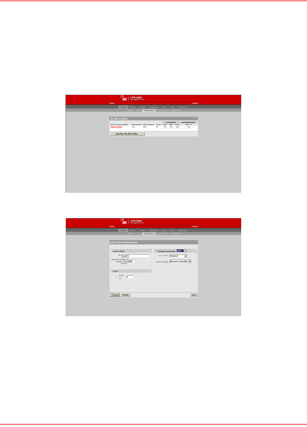
SCP-LPS20x-011-012-01H December 20, 2004
66 ADC Telecommunications, Inc.
WLAN PROFILES
The LPS-20x enables you to create multiple wireless networks all sharing the same wireless port. Each network has
its own SSID (network name) and configuration settings that are defined in a profile. Up to 16 profiles can be
created.
To create a wireless profile
1. On the main menu, click Wireless, and then click WLAN profiles. The WLAN profiles page opens. Initially,
it displays the default WLAN profile.
2. Click Add New Profile.
3. Specify the settings for the profile. Refer to the sections that follow for details.
4. Click Save when you are done.

December 20, 2004 SCP-LPS20x-011-012-01H
ADC Telecommunications, Inc. 67
ACCESS POINT PARAMETERS
Enable this option to activate the wireless access point. When this option is disabled, wireless client stations will not
be able to connect.
WLAN name (SSID)
Specify a name to uniquely identify your wireless network. Each client computer that wants to connect to this profile
must use this name. The name is case-sensitive.
Maximum number of wireless client stations
Specify the maximum number of wireless client stations that can be associated with this SSID at the same time.
Broadcast WLAN name (SSID)
When this option is enabled, the LPS-20x will broadcast its wireless network name (SSID) of this profile to all client
stations. Most wireless adapter cards have a setting that enables them to automatically discover access points that
broadcast their names and automatically connect to the one with the strongest signal.
If you disable this option, client stations will have to specify the network name you enter for WLAN name when they
connect.
VLAN PARAMETERS
VLAN ID
Assigns a VLAN ID to the wireless network. The LPS-20x bridges all wireless traffic with the matching VLAN on the
Internet port.
!
IMPORTANT The total number of wireless client stations that can be connected to the LPS-20x at the same time
across all WLAN profiles is 254.
Only 100 customers can be logged into the public access interface at one time. Customers that
are not logged in can still make use of the wireless network to access public resources (i.e., those
resources specified in the white list or with an access list “accept”).
!
IMPORTANT Enabling this feature bypasses all security features enabled on the LPS-20x. Make sure that your
VLAN has the appropriate security installed to protect access to the network.
The LPS-20x also provides per-user VLAN support.

SCP-LPS20x-011-012-01H December 20, 2004
68 ADC Telecommunications, Inc.
WIRELESS PROTECTION PARAMETERS
Select the type of protection you want to use for the wireless network.
WPA
This option enables support for users with WPA client software.
Key Source
This option determines how the TKIP keys are generated.
• RADIUS: The LPS-20x obtains the MPPE key from the RADIUS server. This is a dynamic key that
changes each time the user logs in and is authenticated. The MPPE key is used to generate the TKIP
keys that encrypt the wireless data stream. Select the appropriate RADIUS server.
WPA sessions are terminated by the LPS-20x. This means that the LPS-20x handles all authentication
tasks and must communicate with the RADIUS server or access controller to validate login credentials.
The LPS-20x sends this authentication traffic on the downstream port. Therefore, the RADIUS server or
access controller must be reachable via this port.
• Preshared Key: The LPS-20x uses the key you specify in the Key field to generate the TKIP keys that
encrypt the wireless data stream. Since this is a static key, it is not as secure as the RADIUS option.
Specify a key that is between 8 and 64 characters in length. It is recommended that the preshared key be
at least 20 characters long, and be a mix of letters and numbers.
RADIUS Profile
Only valid value is Access Controller.
802.1x
This option enables support for users with 802.1x client software. The LPS-20x supports 802.1x client software that
uses EAP-TLS, EAP-TTLS, and PEAP.
Note that all authentication tasks are handled by the LPS-20x and not the wireless client station. This means that the
RADIUS server must be reachable via the downstream port.
RADIUS profile
Communications with the RADIUS server is handled via the access controller. This setting cannot be changed.
Dynamic WEP encryption
Enable the use of dynamic WEP keys for all 802.1x sessions. Dynamic key rotation occurs on key 1, which is the
broadcast key. Key 0 is the pairwise key. It is automatically generated by the LPS-20x.
Key length and key change interval are set in the Dynamic keys box.

December 20, 2004 SCP-LPS20x-011-012-01H
ADC Telecommunications, Inc. 69
WEP
Key 1, 2, 3, 4
The number of characters you specify for a key determines the level of encryption the LPS-20x will provide.
• For 40-bit encryption, specify 5 ASCII characters or 10 HEX digits
• For 128-bit encryption, specify 13 ASCII characters or 26 HEX digits
When encryption is enabled, wireless stations that do not support encryption cannot communicate with the LPS-20x.
The definition for each encryption key must be the same on the LPS-20x and all client stations. Keys must also be in
the same position. For example, if you are using key 3 to encrypt transmissions, then each client station must also
define key 3 to communicate with the LPS-20x.
Transmission Key
Select the key the LPS-20x will use to encrypt transmitted data. All four keys are used to decrypt received data.
Key format
Select the format you used to specify the encryption keys:
ASCII
ASCII keys are much weaker than carefully chosen HEX keys. You can include ASCII characters between 32 and
126, inclusive, in the key. However, note that not all client stations support non-alphanumeric characters such as
spaces, punctuation, or special symbols in the key.
HEX
Your keys should only include the following digits: 0-9, a-f, A-F
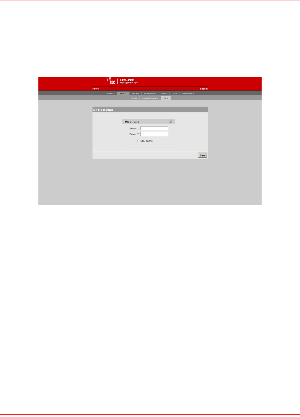
SCP-LPS20x-011-012-01H December 20, 2004
70 ADC Telecommunications, Inc.
DNS MANAGEMENT
OVERRIDING DYNAMICALLY ASSIGNED DNS SERVERS
If required, you can override the DNS servers dynamically assigned by PPPoE or DHCP as follows:
1. In the management tool, click Network, then click DNS. The DNS configuration page opens.
2. Specify the addresses of Server 1 and Server 2.
3. Click Save when you are done.
DNS SERVER PARAMETERS
Server 1
Specify the IP address of the first DNS server that the LPS-20x will use.
Server 2
Specify the IP address of the second DNS server that the LPS-20x will use.
DNS cache
Enables the DNS cache. Once the host name has been successfully resolved to an IP address by a remote DNS
server, it is stored in the cache. This speeds up network performance as the remote DNS server now does not have
to be queried for subsequent requests for this host.
The entry stays in the cache until:
• an error occurs when connecting to the remote host
• the time to live (TTL) of the DNS request expires
• the LPS-20x is restarted
SETTING UP A MULTI-CELL WIRELESS NETWORK
Multiple LPS-20xs are installed in conjunction with a RADIUS Server to provide multiple wireless cells for coverage
of large locations. Client computers are able to move between cells (called roaming) without losing contact with the
network. This is possible because wireless adapters automatically switch to the best available wireless access point.
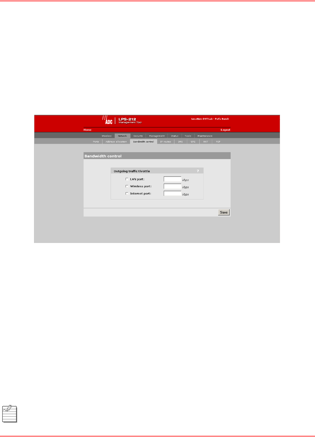
December 20, 2004 SCP-LPS20x-011-012-01H
ADC Telecommunications, Inc. 71
OPERATING FREQUENCY
When using multiple units, it is important that each pair of wireless cells that overlap be set to operate on a different
channel. This helps to eliminate crosstalk and increase performance. For information on selecting operating
frequencies, refer to Configuring Overlapping Wireless Cells on page 72.
NETWORK BANDWIDTH CONTROL
These parameters enable you to limit the flow of data traffic through the LPS-20x by controlling the outgoing
bandwidth allocated to each port.
1. On the Network menu, click Bandwidth control.
OUTGOING TRAFFIC THROTTLE PARAMETERS
These parameters enable you to limit the data traffic through the LPS-20x by controlling the outgoing bandwidth
allocated to each port. Note that the LPS-212 is shown, but the LPS-20x screen is identical to the LPS-212.
• If outgoing traffic arrives at the port at the defined bandwidth limit (or less), it is processed without delay.
• If outgoing traffic arrives at the port at a rate that is greater than the defined bandwidth limit, it causes the
LPS-20x to throttle the traffic for that port.
• If the traffic rate is over-limit for just a short burst, the data will be queued and forwarded without loss. If
the traffic rate is over-limit for sustained period, the LPS-20x will drop data to bring the rate down to the
bandwidth limit that is set.
Examples:
• If you want to limit the traffic that wireless client stations can download from the Internet to 500 kbps, set a
value of 500 for the wireless port.
• If you want to limit the traffic that LAN client stations can download from the Internet to 1000 kbps, set a
value of 1000 for the LAN port.
• If you want to limit the traffic that wireless and LAN client stations can upload to the Internet to 800 kbps,
set a value of 800 for the Internets port.
These are aggregate values per port and not per user values.
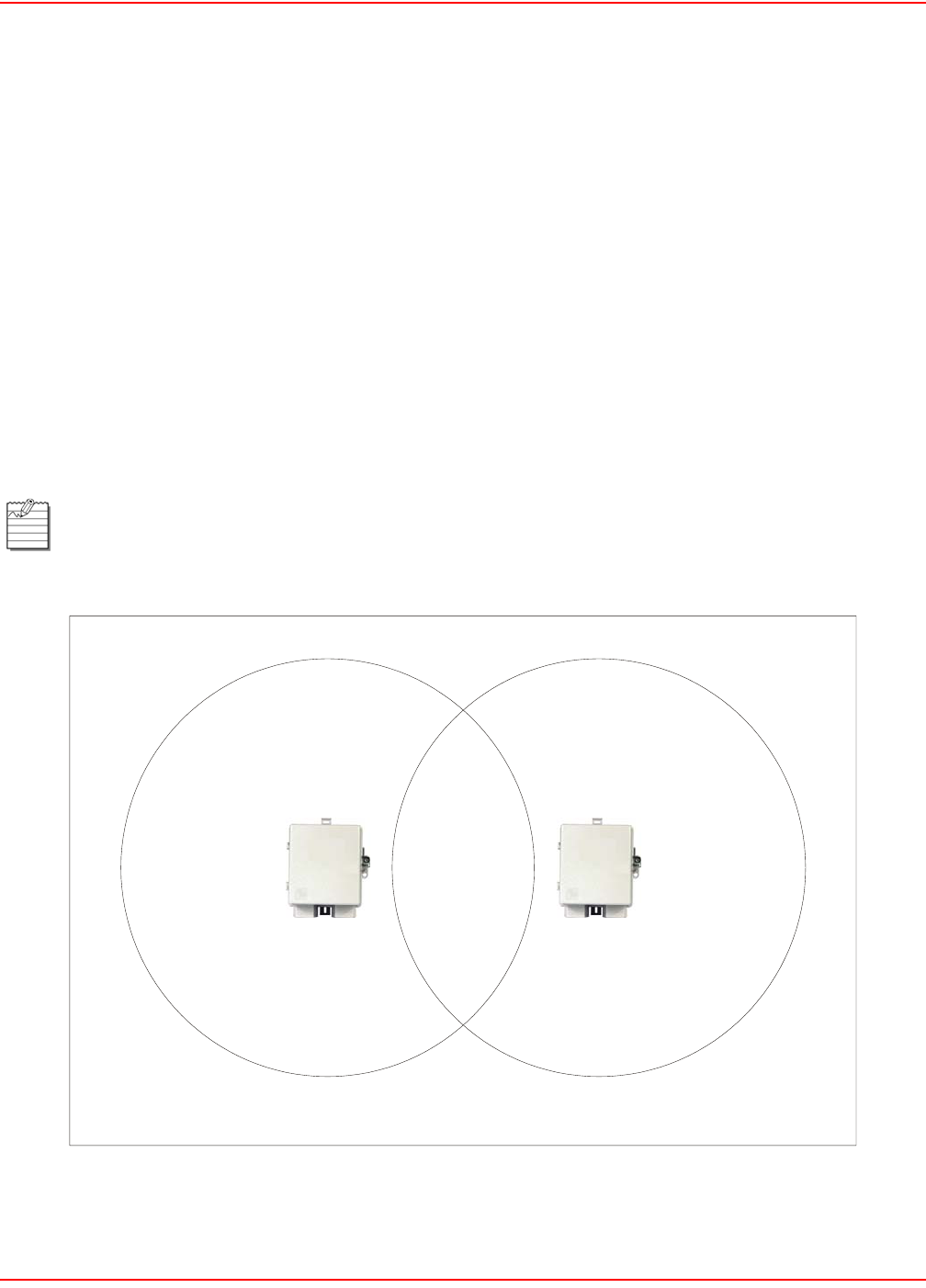
SCP-LPS20x-011-012-01H December 20, 2004
72 ADC Telecommunications, Inc.
CONFIGURING OVERLAPPING WIRELESS CELLS
Overlapping wireless cells are caused when two or more access points are within transmission range of each other.
This may be under your control (when setting up multiple cells to cover a large location) or out of your control (when
your neighbors set up their own wireless networks.). In either case, the problems you face are similar.
PERFORMANCE DEGRADATION AND CHANNEL SEPARATION
When two wireless cells operating on the same frequency overlap, it can cause a reduction in throughput in both
cells. This occurs because a wireless station that is attempting to transmit will defer (delay) its transmission if
another station is currently transmitting. On a network with many clients and a lot of traffic, this can severely affect
performance as stations defer multiple times before the channel becomes available. If a station is forced to delay its
transmission too many times, data may be lost.
Delays and lost transmissions can severely reduce throughput on a network. Use the Wireless option on the Status
menu to view this information on your network.
Figure 17 shows two overlapping wireless cells operating on the same frequency. Since both access points are
within range of each other, the number of deferred transmissions will be large.
Figure 17. Overlapping Wireless Cells on Same Frequency
Overlapping wireless cells can cause transmission delays.
cell 1 cell 2
05
-LP
S
2
0
xR1

December 20, 2004 SCP-LPS20x-011-012-01H
ADC Telecommunications, Inc. 73
The solution to this problem is to set the two networks to different channels with as great a separation as possible in
their operating frequencies. This reduces cross-talk and enables client stations connected to each access point to
transmit at the same time.
CHOOSING CHANNELS
For optimum performance when operating in 802.11b mode, choose a frequency that differs from other wireless
access points operating in neighboring cells by at least 25 MHz. (Note that this is the recommended minimum. Two
channels with this separation will always perform worse than two channels using the maximum separation. So it is
always best to use the greatest separation possible between overlapping networks.)
Consult the Wireless > Neighborhood page to view a list of access points currently operating in your area.
With the proliferation of wireless networks, it is very possible that the wireless cells of access points outside your
control may overlap your intended area of coverage. To generate a list of all access points operating near you and
view their operating frequencies, go to Wireless > Neighborhood.
The set of available channels is automatically determined by the LPS-20x, based on the Country setting that has
been programmed into the firmware. Available channels can be viewed on the Wi-Fi page. This means that the
number of non-overlapping channels available to you will vary. This will affect how you set up your multi-cell
network.
Channel Availability
The LPS-20x supports the following 14 channels in the 2.4 GHz band (Table 11).
Table 11. Supported Channels
Channel Frequency
12412
22417
32422
42427
52432
62437
72442
82447
92452
10 2457
11 2462
12 2467
13 2472
14 2477

SCP-LPS20x-011-012-01H December 20, 2004
74 ADC Telecommunications, Inc.
Different regions have specified maximum transmit power and channel availability (Table 12). The number of
channels available in a particular country are determined by the regulations defined by the local governing body.
Table 12. Maximum Transmit Power and Channel Availability
Since the minimum recommended separation between overlapping channels is 25 MHz (five cells), then the
recommended maximum number of overlapping cells you can have in most regions is three (Table 13).
Table 13. Channel Availability
Region
Maximum Transmit
Power
Channel
Availability
North America 200 mW 1-11
ETSI 100 mW 1-13
France 100 mW 10-13
Japan 100 mW 1-14
Spain 100 mW 10-11
North America Europe Japan
cell 1 on channel 1 cell 1 on channel 1 cell 1 on channel 1
cell 2 on channel 6 cell 2 on channel 7 cell 2 on channel 7
cell 3 on channel 11 cell 3 on channel 13 cell 3 on channel 14