ADC Telecommunications M64-25 TurboMax Base Station User Manual
ADC Telecommunications Inc. TurboMax Base Station Users Manual
UserManual.wiki
>
ADC Telecommunications
>
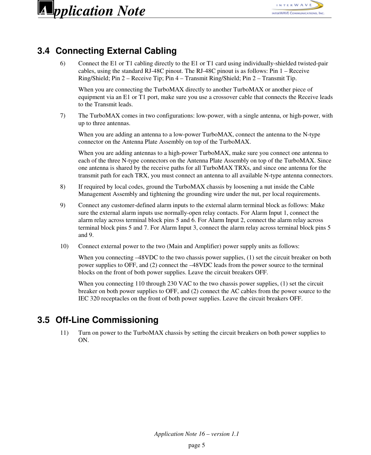
M64 25 User Manual
Users Manual
Navigation menu
Upload a User Manual
Namespaces
Wiki Guide
HTML
PDF
Info
Views
User Manual
Discussion / Help
Navigation
![Application Note 16 – version 1.1page 8pplication NoteAIW206001ON/LINEPORT 112PORT 012ALARMSFLTPWRALARMSCraft PCcomputerIWP, 64MEG, MMUHARD DISKDB-9 portconnectorDB-9 extension cableDB-9 portconnectorONLINEPWRFLTSCNRSTCONENETEXTXREFFigure 4. Connecting the Craft PC to the TurboMAX via the Serial Port15) Power up the Craft PC, and allow the Linux operating system to bootup.16) Logon as ‘build’, and start XWindows by entering ‘startx’.17) Establish serial communications with the TurboMAX by entering ‘cu –l ttyS0 –s 9600’. TheTurboMAX responds with ‘Connected’. Press the [ENTER] key to display the ‘bts:A->’ prompt.](https://usermanual.wiki/ADC-Telecommunications/M64-25/User-Guide-130286-Page-8.png)
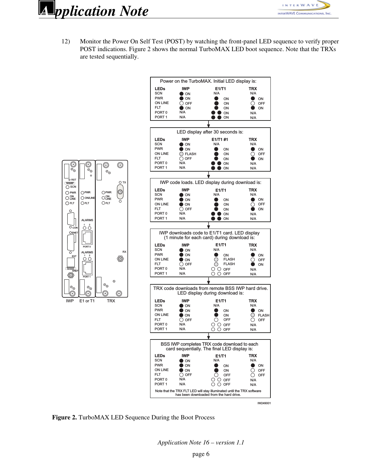
![Application Note 16 – version 1.1page 9pplication NoteA18) Verify the boot parameters by entering ‘bootChange’. A list of parameters appears as you press the[ENTER] key, as shown in Figure 5.’.’ = clear field; ’-’ = go to previous field; ^D = quitboot device : quprocessor number : 0host name : craftpcfile name : /home/target/vxWorksinet on ethernet (e) : 172.16.80.42:fffff000inet on backplane (b):host inet (h) : 172.16.80.43gateway inet (g) :user (u) : targetftp password (pw) (blank = use rsh):flags (f) : 0xatarget name (tn) : btsstartup script (s) : /home/target/iwvstartother (o) :Figure 5. Verifying/Changing TurboMAX Boot ParametersMake sure the parameters include the listed values. If so, continue with the next step. If not, reenter‘bootChange’, press the [ENTER] key to display the desired line, press period ‘.’ to delete theincorrect entry, type in the correct entry, and press the [ENTER] key to continue with the nextparameter. When all the bootChange parameters display the correct values, continue with the nextstep.19) Reboot the TurboMAX by pressing the [CTRL][x] key combination. Verify the current softwareversion and patch level by pressing [RETURN] to display the ‘bts:A->’ prompt. Then enter‘iwversion’. The TurboMAX responds with the BSX code version, the software release, theencryption status, and the patches currently installed. Verify that you have the software versioniw05_00.132 or later installed.20) Verify the images loaded in the TurboMAX IWP flash version by entering ‘printConfigBlocks’. Theresulting parameters display the Primary Config Block imageCurrent and Secondary Config BlockimageCurrent entries in the form ‘iwXX_YY.ZZZ’, which indicates the IWP flash version. ContactTechnical Support to ensure you have IWP flash version iw05_00.132 or later installed.21) Run the E1 or T1 POST diagnostics by disconnecting all E1 and T1 lines from the TurboMAX,entering ‘reboot’ at the ‘bts:A->’ prompt. Verify that the resulting seven sequential tests appear as‘PASSED’. If the E1 or T1 Trunk card fails any of these tests, the E1 or T1 card is defective; returnthe E1 or T1 card to interWAVE, and redo this test with the replacement E1 or T1 Trunk card.22) Terminate any existing telnet and/or rlogin session by logging in as root (bts:A-> su – root), clearingexisting sessions (# /sbin/arp –d iwbox), and logging out of root (# exit).](https://usermanual.wiki/ADC-Telecommunications/M64-25/User-Guide-130286-Page-9.png)
![Application Note 16 – version 1.1page 10pplication NoteA23) Verify telnet communications with the IWP card by terminating the serial connection by entering‘~.’ (tilde .), which returns the prompt to ‘build@craftpc:~>’.After the serial connection is terminated, enter ‘telnet bts’ to display the ‘bts:A->’ prompt. Thisshows that you are able to set up a telnet session with the TurboMAX.Terminate the telnet session by entering ‘logout’. This causes the TurboMAX to display ‘Connectionclosed by foreign host’ and the prompt changes back to ‘build@craftpc:~>’.24) Reestablish a serial connection with the TurboMAX by entering ‘cu –l ttyS0 –s 9600’. TheTurboMAX responds with ‘Connected’. Press the [ENTER] key to display the ‘bts:A->’ prompt.25) At the ‘bts:A->’ prompt, enter ‘runtrxpost’ to test the TRX card(s). The resulting output contains theoutput for the various TRX tests, including one line for each TRX that reads: ‘TRX CARD IN SLOT<2, 4, or 6>: COMPLETED TRX POST OFFLINE TEST: <PASSED/FAILED>’.26) Review the E1/T1 and BTS POST test results by entering ‘postReportE1Trx’. The TurboMAXdisplays a summary of the E1/T1 and TRX test results, which should all appear as ‘PASSED’ exceptthose which appear as ‘NOT-RUN’.27) Reboot the TurboMAX after running the POST tests by entering ‘reboot’ at the ‘bts:A->’ prompt.28) Have the E1 or T1 link provider certify that the links pass a BER (Bit Error Rate or Bit Error Ratio)test at 10-8 or better over 20 minutes.29) Reconnect all E1 or T1 cables disconnected to run the POST tests.3.6 Performing Racal Tests30) Perform the Racal Test procedures for the TurboMAX as described in the interWAVE FieldMaintenance Guide for the 16W TurboWAVE. The only difference is that the output power of theTurboMAX is slightly higher.3.7 Off-Line Commissioning of a TurboMAX Daisy ChainThis is an optional section, and is only required if multiple TurboMAXs are to be daisy-chained off of aBSC, BS Plus, or NIB. If this configuration is used, each TurboMAX must be installed separately, and musthave off-line commissioning procedures independently performed. Once each TurboMAX is installed andcommissioned, the TurboMAXs can be daisy chained together.31) Before connecting any TurboMAXs, ensure that they are all installed and off-line commissioned.32) Ensure that all the TurboMAXs have been tested using the Racal Test Set.33) Ensure that a different Abis link has been set for each TurboMAX using the Abis Manager time slothas been set for each TurboMAX as follows:After each TurboMAX has been Racal tested, enter ‘getFlashE1Chan’ at the Craft PC ‘bts:A->’prompt. The TurboMAX displays the timeslot reserved for the LAPD signaling timeslot (default =16).To change this value, enter ‘setFlashE1Chan <timeslot>’ at the Craft PC ‘bts:A->’ prompt,where<number> is any unassigned E1 or T1 timeslot between 1 and 31, or between 1 and 24,respectively.Note that interWAVE recommends the following Abis timeslot assignments: First TurboMAX in thedaisy chain, Abis timeslot = 16. Second TurboMAX in the daisy chain, Abis timeslot = 17. Third](https://usermanual.wiki/ADC-Telecommunications/M64-25/User-Guide-130286-Page-10.png)
![Application Note 16 – version 1.1page 11pplication NoteATurboMAX in the daisy chain, Abis timeslot = 18. Fourth TurboMAX in the daisy chain, Abistimeslot = 19.Verify that the Abis timeslot has been changed correctly. Enter ‘getFlashE1Chan’ at the ‘bts:A->’prompt. The TurboMAX displays the timeslot reserved for the LAPD signaling timeslot.34) Reboot each TurboMAX by entering ‘reboot’ at the ‘bts:A->’ prompt.35) After all TurboMAXs in a daisy chain have been assigned unique Abis LAPD links, connect them toeach other and to the associated BSC, BS Plus, or NIB with E1 or T1 links as described in Section3.4.3.8 Shutting Down the Craft PC and Disconnecting the Serial andEthernet Connections36) Terminate the serial connection with the TurboMAX by entering ‘~.’ (tilde .), which returns theprompt to ‘build@craftpc:~>’.37) Exit the XWindows session by pressing [CTRL][ALT] and [BACKSPACE] simultaneously. At the‘build@craftpc:~>”’ prompt, enter ‘exit’.38) At the ‘craftpc login:’ prompt enter ‘root’ to display the ‘craftpc:~#’ prompt.39) Shut down the Craft PC operating system by entering ‘shutdown –h now’. After about one minute,the Craft PC displays ‘System halted’ and ‘INIT: No more processes left in runlevel 0’.40) Turn off the Craft PC by toggling the power switch. The serial and ethernet connections can now beremoved between the Craft PC and the TurboMAX.41) Inform the OMC operator that the TurboMAX is ready for on-line commissioning.3.9 On-Line CommissioningOn-line commissioning of the TurboMAX requires that an on-site field engineer work with the OMCoperator, after installation and off-line commissioning.42) Verify that the TurboMAX is fully commissioned, that it is connected to a BSC, BS Plus, or NIBnetwork element, and that the OMC is communicating with the connected network element.43) Have the operator verify that the RF frequencies are cleared to transmit.44) Have the OMC operator download the TurboMAX configuring and correct software version andoperational parameters as defined in the WAVEView OMC Operations and Maintenance Guide andthe interWAVE Network Implemetation Manual.45) Have the OMC operator perform the following:Create a planned cell in the OMC database corresponding to this TurboMAX. The planned cellshould at minimum include the Cell ID and LAC for the TurboMAX.Define neighbor relationships for the planned cell.Create a managed cell from the planned cell.Set the TurboMAX parameters, including its base station identity code.Set the TurboMAX Abis parameters, including the corresponding E1 or T1 card slot and AbisLAPD link.](https://usermanual.wiki/ADC-Telecommunications/M64-25/User-Guide-130286-Page-11.png)