ADC Telecommunications PRSMAW4A FlexWave™ Prism - AWS 40 Watt User Manual 77073
ADC Telecommunications Inc FlexWave™ Prism - AWS 40 Watt 77073
Contents
- 1. User manual 1
- 2. User manual 2
- 3. User manual 3
User manual 1
ADC FlexWave™ Prism
Host, Remote and EMS 5.1
System Reference
D-620098-0-20 Rev B
Antenna
Antenna
Antenna
Quad Band
Remote Unit
Host Unit
Antenna
77073-001
ADCP-77-073 x Issue 2 x 11/2009

ADC Telecommunications, Inc.
P.O. Box 1101, Minneapolis, Minnesota 55440-1101
In U.S.A. and Canada: 1-800-366-3891
Outside U.S.A. and Canada: (952) 938-8080
Fax: (952) 917-1717
Copyright
© 2009 ADC Telecommunications, Inc. All Rights Reserved.
Information contained in this document is company private to ADC Telecommunications, Inc. and
shall not be modified, used, copied, reproduced or disclosed in whole or in part without the written
consent of ADC.
Trademark Information
ADC is a registered trademark and FlexWave is a trademark of ADC Telecommunications, Inc. No
right, license, or interest to such trademarks is granted hereunder, and you agree that no such right,
license, or interest shall be asserted by you with respect to such trademark.
Other product names mentioned in this practice are used for identification purposes only and may
be trademarks or registered trademarks of their respective companies.
Disclaimer of Liability
Contents herein are current as of the date of publication. ADC reserves the right to change the
contents without prior notice. Should the content of printed user documentation shipped with
product differ from documentation provided on a product CD (inclusive of the associated Help
modules), the printed user documentation supersedes the documentation on the product CD. In no
event shall ADC be liable for any damages resulting from loss of data, loss of use, or loss of profits,
and ADC further disclaims any and all liability for indirect, incidental, special, consequential or other
similar damages. This disclaimer of liability applies to all products, publications and services during
and after the warranty period.
Specific Disclaimer for High-Risk Activities
This Software Product is not specifically designed, manufactured, tested or intended for use in high-
risk activities including, without restricting the generality of the foregoing, on-line control of aircraft,
air traffic, aircraft navigation or aircraft communications; or in the design, construction, operation
or maintenance of any nuclear facility. ADC (including its affiliates) and its suppliers specifically
disclaim any express or implied warranty of fitness for such purposes or any other purposes.
Screenshots in User Documentation
Due to concurrent development of this documentation, artwork, and the FlexWave URH EMS
product, there may be some minor discrepancies between screenshots contained in this
documentation and those actually displayed in the FlexWave URH EMS. These discrepancies will
generally be few and minor and should not affect your understanding of FlexWave URH EMS.

FlexWave Prism Host, Remote and EMS 5.1 System Reference Page iii
ADCP-77-073 • Issue 2 • 11/2009 ©2009 ADC Telecommunications, Inc.
TABLE OF CONTENTS
Preface _______________________________________________ix
FlexWave Prism User Documentation........................................................................... x
Following the EMS Procedures in This Document ...........................................................xi
General Safety Precautions .......................................................................................xii
Standards Certification ............................................................................................ xiii
Part I: FlexWave Prism System Overview ____________1
Chapter 1: FlexWave Prism System _________________________ 3
1.1 Prism System Overview ....................................................................................... 4
1.1.1 Product Features ......................................................................................... 4
1.1.2 Applications ................................................................................................ 5
1.2 Basic System Components.................................................................................... 6
1.3 Multi-Host Systems ........................................................................................... 10
1.4 DART Cards...................................................................................................... 12
1.4.1 DARTs and Host Units ................................................................................ 13
1.4.2 DARTs and Remote Units ............................................................................ 15
1.5 E911 Support ................................................................................................... 16
1.6 Fiber Optic Transport ......................................................................................... 17
1.7 Timeslots Versus Bandwidth ............................................................................... 19
1.8 Bandwidths ...................................................................................................... 20
1.9 AWS and PCS Band Options................................................................................ 24

Page iv FlexWave Prism Host, Remote and EMS 5.1 System Reference
© 2009 ADC Telecommunications, Inc ADCP-77-073 • Issue 2 • 11/2009
Chapter 2: Prism System Components ______________________ 27
2.1 FlexWave Prism Family Overview ........................................................................ 28
2.2 FlexWave Prism Host Units ................................................................................. 30
2.2.1 Host Front Panel........................................................................................ 30
2.2.2 Host Network Connection ........................................................................... 33
2.2.3 Host RF Signal Connections......................................................................... 33
2.2.4 Host System Card...................................................................................... 34
2.3 Prism Remote Units ........................................................................................... 35
2.3.1 Handset Interface...................................................................................... 36
2.3.2 Remote Components.................................................................................. 36
2.3.2.1 Remote RF Modules............................................................................ 38
2.3.2.1.1 Remote Duplexer and Low Noise Amplifier ..................................... 40
2.3.2.1.2 Linear Power Amplifiers............................................................... 41
2.3.2.2 Remote SeRF Modules ........................................................................ 43
2.3.2.3 Remote Power Supply and Cable Assembly............................................ 44
2.3.2.4 Solar Shield ...................................................................................... 45
2.3.2.5 Mounting Bracket (Remotes) ............................................................... 46
2.3.2.6 Remote Connectors............................................................................ 47
2.3.2.7 Remote Fiber Connector Cable Assembly............................................... 49
2.3.2.8 Remote Antenna Cable Connections ..................................................... 49
2.3.2.9 Remote Grounding ............................................................................. 49
2.3.2.10 Remote Cooling ............................................................................... 49
2.4 Prism System Accessories .................................................................................. 50
2.4.1 Lightning Surge Suppressor (Remote Accessory) ........................................... 50
2.4.2 Uninterruptible Power Supply (Accessory) ..................................................... 50
2.4.3 Wavelength Division Multiplexer System (Accessory)...................................... 50
2.4.4 Course Wavelength Division Multiplexer System (Accessory) ........................... 51
2.4.5 Millimeter Wave Systems (Accessory) .......................................................... 55
2.5 Prism System Specifications ............................................................................... 56
2.5.1 Host Unit Specifications .............................................................................. 56
2.5.2 Remote Unit Specifications ......................................................................... 57
2.5.3 System Nominal Optical Specifications.......................................................... 58
Part II: Host and Remote Installation ______________ 61
Chapter 3: Installing the Host Unit ________________________ 63
3.1 Before Starting Installation................................................................................. 64
3.2 Tools and Materials............................................................................................ 65
3.3 Install the Host ................................................................................................. 66
3.3.1 Unpacking and Inspection........................................................................... 66
3.3.2 Install Host in Equipment Rack .................................................................... 66
3.3.3 OSP Fiber Cable Installation Guidelines......................................................... 68
3.3.4 Chassis Ground Connection......................................................................... 69
3.3.5 Coaxial Cable Connections .......................................................................... 70
3.3.6 Optical Connections ................................................................................... 72
3.3.7 LC Attenuator ........................................................................................... 73
3.3.7.1 Optical Connections Without WDM System ............................................ 74
3.3.7.2 Optical Connections For Systems With a WDM ....................................... 76
3.3.8 EXT REF Connections ................................................................................. 78
3.3.9 Computer Connection (Craft) ...................................................................... 80
3.3.10 System Alarm Connections........................................................................ 81
3.3.11 Power Connections................................................................................... 83

FlexWave Prism Host, Remote and EMS 5.1 System Reference Page v
ADCP-77-073 • Issue 2 • 11/2009 © 2009 ADC Telecommunications, Inc.
3.4 Installing the WDM Host Module Mounting Shelf and WDM Host Module .................... 87
3.4.1 Wavelength Division Multiplexer System Overview ......................................... 87
3.4.2 Install WDM Host Components .................................................................... 90
Chapter 4: Installing the Remote Unit ______________________ 93
4.1 Remote Installation Overview ............................................................................. 94
4.1.1 Installation Hardware Provided with Remote.................................................. 94
4.1.2 Required Tools and Materials....................................................................... 95
4.2 Remote Mounting Plans...................................................................................... 96
4.3 Install the Remote............................................................................................. 97
4.3.1 Unpack and Inspect the Remote and Components .......................................... 97
4.3.2 Install the Remote RF Module(s) .................................................................. 98
4.4 Install any 40W RF Module(s) ............................................................................107
4.4.1 Prepare the Remote and RF Module.............................................................108
4.4.2 Remove Module Shelf(s)............................................................................108
4.4.3 Install the 40W RF Module .........................................................................110
4.4.4 Ground Wire Installation............................................................................118
4.4.5 Network Cable Installation .........................................................................119
4.4.6 Quad Fiber Cable Installation .....................................................................121
4.4.7 Antenna Cable Installation .........................................................................123
4.4.8 AC Power Wiring Installation ......................................................................125
4.4.9 Determine the Circuit Breaker or Fuse for Remote.........................................129
4.4.9.1 Power Consumption ..........................................................................129
4.4.9.2 Power Consumption Tables.................................................................131
4.4.10 Mount the Remote and Power Up ..............................................................132
Part III: System Setup and Management __________133
Chapter 5: FlexWave Element Management System __________ 135
5.1 FlexWave EMS Overview ...................................................................................136
5.2 EMS Graphical User Interface.............................................................................138
5.3 Product Identity ...............................................................................................139
5.4 EMS Menu Bar .................................................................................................140
5.5 EMS Alarm Indications ......................................................................................141
5.6 EMS System Requirements ................................................................................142

Page vi FlexWave Prism Host, Remote and EMS 5.1 System Reference
© 2009 ADC Telecommunications, Inc ADCP-77-073 • Issue 2 • 11/2009
Chapter 6: Initial Prism System Setup _____________________ 143
6.1 Access the EMS................................................................................................144
6.2 Discover IP Addresses.......................................................................................146
6.3 Enter a Host Name, Clock Source, and Linking Mode .............................................147
6.4 Set the Clock Priority Level................................................................................150
6.5 Provision the Host SeRF Optical Ports..................................................................151
6.6 Configure the Host DARTs .................................................................................152
6.7 Enter a Remote Name.......................................................................................156
6.8 Configure the Remote SeRF Optical Ports ............................................................158
6.9 Link the Host and Remote DARTs. ......................................................................159
6.9.1 Use of Multi Fibers ....................................................................................159
6.9.2 RF Groups in the Remote and the EMS GUI ..................................................160
6.9.3 Link a Remote DART to a Host DART ...........................................................162
6.10 Conclude Initial System Setup..........................................................................167
6.11 (Optional) Configuring Multi-Host Systems for Manual Mode .................................168
6.11.1 Set the Multi-Host System to Manual Mode ................................................168
6.11.2 Configure the Host DARTs........................................................................168
6.11.3 Configure the Remote DARTs ...................................................................173
Chapter 7: Using the EMS to Manage a Prism System _________ 177
7.1 Displaying the System View...............................................................................178
7.2 Setting Auto Refresh.........................................................................................179
7.3 Working with the System Inventory ....................................................................180
7.3.1 System Inventory View Components ...........................................................180
7.3.1.1 System Inventory and Host Inventory Tables........................................181
7.3.1.2 Remote Inventory Tables ...................................................................182
7.4 Working with Prism System Network Interfaces....................................................184
7.4.1 Changing to Built-In Network Mode.............................................................186
7.4.2 EMS Access Methods.................................................................................188
7.4.2.1 Accessing the EMS Through the Remote Network Port............................189
7.4.2.2 Accessing the EMS Through the Remote Craft Port ................................192
Chapter 8: Managing User Accounts_______________________ 195
8.1 FlexWave EMS User Accounts ............................................................................196
8.2 Viewing User Accounts......................................................................................197
8.3 Adding a User Account ......................................................................................198
8.4 Changing a User Access Level ............................................................................202
8.5 Changing the Password of Another User ..............................................................206
8.6 Changing Your Own Password ............................................................................208
8.7 Deleting a User Account ....................................................................................210
Chapter 9: Managing Host Units__________________________ 213
9.1 Viewing the Host Summary ...............................................................................214
9.2 Resetting the Host Unit .....................................................................................215
9.3 Viewing Host SeRF Ethernet Ports.......................................................................217
9.4 Decommissioning a DART in a Host.....................................................................220
9.5 Viewing the Host SeRF Summary .......................................................................222
9.6 Viewing Host SeRF Optical Ports.........................................................................224
9.7 Viewing Host DART Alarms ................................................................................226

FlexWave Prism Host, Remote and EMS 5.1 System Reference Page vii
ADCP-77-073 • Issue 2 • 11/2009 © 2009 ADC Telecommunications, Inc.
Chapter 10: Managing Remote Units ______________________ 229
10.1 Viewing Remote SeRF Ethernet Ports.................................................................230
10.2 Decommissioning an RF Module in a Remote ......................................................232
10.3 Configuring Dual-Slot LPAs ..............................................................................235
10.4 Restarting an LPA ...........................................................................................236
10.4.1 Identify the LPA Fault ..............................................................................236
10.4.2 Reset the LPA.........................................................................................238
10.5 Monitoring a Remote Unit ................................................................................240
10.6 Decommissioning a Remote Unit.......................................................................244
10.7 Resetting a Remote Unit..................................................................................246
10.8 Viewing Remote SeRF Alarms...........................................................................248
10.9 Viewing Remote SeRF Optical Ports...................................................................248
10.10 Viewing an Alarm Summary of the Remote RF Groups .......................................250
10.11 Viewing RF Band Alarm Details .......................................................................252
10.12 Viewing Remote GPS Alarms and Location Parameters .......................................255
Chapter 11: Managing Alarms ___________________________ 257
11.1 Viewing Active Alarms .....................................................................................258
11.2 Viewing an Alarm History Log...........................................................................259
11.3 Masking an Alarm Type ...................................................................................260
11.4 Unmasking an Alarm Type ...............................................................................262
11.5 Troubleshooting Alarms...................................................................................264
Chapter 12: SNMP Interface ____________________________ 275
12.1 EMS SNMP Interface .......................................................................................276
12.2 SNMP Overview..............................................................................................277
12.2.1 Background Information on SNMP .............................................................278
12.2.2 MIB Used by FlexWave System .................................................................280
12.3 SNMP Procedures ...........................................................................................281
12.4 Accessing the FlexWave-Prism Agent MIB ..........................................................282
12.5 Configuring the Trap Viewer.............................................................................283
12.5.1 Registering the Manager for Receiving Traps
(static—non AdventNet MIB Browser) .............................................................283
12.5.2 Registering the Manager for Receiving Traps
(dynamic—AdventNet MIB Browser) ...............................................................284
12.5.3 Viewing Traps.........................................................................................287
12.5.3.1 Date and Time Stamps ....................................................................287
12.5.3.2 Variable Bindings ............................................................................288
12.5.3.3 View the Traps................................................................................290
12.6 FlexWave-URH Agent MIB................................................................................292
12.7 Traps ............................................................................................................308

Page viii FlexWave Prism Host, Remote and EMS 5.1 System Reference
© 2009 ADC Telecommunications, Inc ADCP-77-073 • Issue 2 • 11/2009
Part IV: Appendices __________________________ 311
Appendix A: Host Unit Module Replacement ________________ 313
A.1 Host Fan Replacement Procedure .......................................................................314
A.2 Power Supply Replacement Procedure ................................................................315
A.3 System Card Replacement Procedure..................................................................317
A.4 SeRF Card Replacement Procedure .....................................................................319
A.4.1 Preserve System Configuration...................................................................319
A.4.2 Remove the SeRF Card .............................................................................322
A.4.3 Swap Compact Flash From Old SeRF Card to New SeRF Card..........................323
A.4.4 Install New SeRF Card...............................................................................324
A.5 DART Card Replacement/Installation Procedure....................................................325
A.5.1 Replacing a DART Card in the Host Chassis ..................................................325
A.5.2 Installing a New DART Card in the Host Chassis............................................325
Appendix B: General Information_________________________ 329
B.1 Warranty/Software...........................................................................................329
B.2 Software Service Agreement..............................................................................329
B.3 Repair/Exchange Policy.....................................................................................329
B.4 Repair Charges ................................................................................................330
B.5 Replacement/Spare Products .............................................................................330
B.6 Returned Material ............................................................................................330
Appendix C: Glossary __________________________________ 331
Appendix D: Contacting ADC ____________________________ 335
Index ______________________________________________ 337

FlexWave Prism Host, Remote and EMS 5.1 System Reference Page ix
ADCP-77-073 • Issue 2 • 11/2009 ©2009 ADC Telecommunications, Inc.
PREFACE
FlexWave Prism User Documentation........................................................................... x
Following the EMS Procedures in This Document ...........................................................xi
General Safety Precautions .......................................................................................xii
Standards Certification ............................................................................................ xiii
This document provides basic description, application, and configuration
information about the ADC® FlexWave™ Prism system. The information in this
document guides you through:
•• designing a Prism system
•• installing Prism Host and Remote Units
•• configuring the Prism system through the FlexWave Web-Based Element
Management System (EMS) Version 5.1. The EMS is an embedded software
application that runs on the Host and that may be accessed via an internet
connection using a Web browser. This document shows how to connect to the EMS
software using a SNMP manager to interact with the SNMP database that is used
to store system parameters. SNMP (Simple Network Management Protocol) is an
international standard for remote management of online devices.
Throughout this publication, all items referenced as “accessory items” are not
furnished with the basic product and must be purchased separately.
Content Page
Page x FlexWave Prism Host, Remote and EMS 5.1 System Reference
© 2009 ADC Telecommunications, Inc ADCP-77-073 • Issue 2 • 11/2009
FLEXWAVE PRISM USER DOCUMENTATION
The FlexWave Prism user documentation is intended for system engineers,
administrators, and end users that are responsible for planning, administering,
configuring, and maintaining ADC FlexWave Prism systems. Familiarity with SNMP
and common network technologies is required.
Each FlexWave Prism document describes a different aspect of the FlexWave Prism
system. The following manuals correspond to this FlexWave Prism release:
Icons
Three types of messages, identified by icons, appear in the text:
Title ADCP Number
ADC® FlexWave Prism Host, Remote and EMS 5.1 System Reference 77-073
ADC® FlexWave Prism Host Unit Installation Guide 77-071
ADC® FlexWave Prism Remote Unit Installation Guide 77-072
ADC® FlexWave Prism Remote Mounting Kit Installation Instructions 77-077
ADC® FlexWave Prism Remote RF Module Installation Instructions 77-079
ADC® FlexWave Prism Coarse Wavelength Division Multiplexer User Manual 77-075
The Caution icon indicates operations or steps that could:
••cause personal injury
• induce a safety problem in a managed device
• destroy or corrupt information
• interrupt or stop services.
The Note icon indicates text that contains information about special circumstances.
The User icon indicates text that lists which user roles are required for a procedure or
EMS access.

FlexWave Prism Host, Remote and EMS 5.1 System Reference Page xi
ADCP-77-073 • Issue 2 • 11/2009 © 2009 ADC Telecommunications, Inc.
Fonts
You will find the following font conventions in use throughout the document:
•
This font
indicates a reference to a EMS dialog box, menu item, configuration
option, or other parameter.
•This font indicates text you type at a prompt.
•THIS FONT indicates keys that you need to press on your keyboard.
•• When a procedure requires clicking on a sequence of items, commas separate the
items. For example, “click
User Account Management
,
User Account
” indicates that in
the Function Explorer Tree, you select the
User Account Management
node, and then
select the
User Account
node.
Illustrations
Some illustrations have numeric callouts. These callouts indicate the related step
numbers in the accompanying text.
FOLLOWING THE EMS PROCEDURES IN THIS DOCUMENT
This document includes descriptions of how to use the FlexWave EMS to configure
and manage FlexWave Prism devices.
Starting a Procedure
All procedures in this document assume that you have already logged in to FlexWave
EMS as described in “Access the EMS” on page 144.
Finishing or Canceling a Procedure
In general, the procedures in this document end each procedure with having you click
OK
or
Apply
to accept changes or input. However, you can also click
Close
without
clicking
Apply
to abandon any changes made, or click
Refresh
to update the data being
shown.
The following table describes the most common EMS dialog buttons.
Button Function
OK
Applies your configuration changes and closes the dialog.
Apply
Applies your configuration changes without closing the dialog.
Close
Discards any changes you have made in the dialog—unless you have
previously clicked
Apply
—and closes the dialog. In a performance or
status dialog, closes the dialog.
Refresh
Updates status information to reflect current conditions.
Page xii FlexWave Prism Host, Remote and EMS 5.1 System Reference
© 2009 ADC Telecommunications, Inc ADCP-77-073 • Issue 2 • 11/2009
GENERAL SAFETY PRECAUTIONS
Wet conditions increase the potential for receiving an electrical shock when installing or
using electrically- powered equipment. To prevent electrical shock, never install or use
electrical equipment in a wet location or during a lightning storm.
This equipment uses a Class 1 Laser according to FDA/CDRH rules. Laser radiation can
seriously damage the retina of the eye. Do not look into the ends of any optical fiber. Do
not look directly into the optical transceiver of any digital unit or exposure to laser
radiation may result. An optical power meter should be used to verify active fibers. A
protective cap or hood MUST be immediately placed over any radiating transceiver or
optical fiber connector to avoid the potential of dangerous amounts of radiation
exposure. This practice also prevents dirt particles from entering the adapter or
connector.
This system is an RF Transmitter and continuously emits RF energy. Maintain 3 foot
(91.4 cm) minimum clearance from the antenna while the system is operating. Wherever
possible, shut down the RAN before servicing the antenna.
Always allow sufficient fiber length to permit routing of patch cords and pigtails without
severe bends. Fiber optic patch cords or pigtails may be permanently damaged if bent
or curved to a radius of less than 2 inches (5.1 cm).
Exterior surfaces of the Remote may be hot. Use caution during servicing.

FlexWave Prism Host, Remote and EMS 5.1 System Reference Page xiii
ADCP-77-073 • Issue 2 • 11/2009 © 2009 ADC Telecommunications, Inc.
STANDARDS CERTIFICATION
FCC:: This equipment complies with the applicable sections of Title 47 CFR Part 15
(Host unit), Part 22 (800 MHz Cellular), Part 24 (1900 MHz - PCS), Part 90 (800/900 -
SMR), and Part 27 (2100 MHz - AWS).
IC:: This equipment complies with the applicable sections of RSS-131. The term “IC:”
before the radio certification number only signifies that Industry Canada Technical
Specifications were met.
The Manufacturer's rated output power of this equipment is for single carrier
operation. For situations when multiple carrier signals are present, the rating would
have to be reduced by 3.5 dB, especially where the output signal is re-radiated and
can cause interference to adjacent band users. This power reduction is to be by
means of input power or gain reduction and not by an attenuator at the output of the
device.
Note:: To comply with Maximum Permissible Exposure (MPE) requirements, the
maximum composite output form the antenna cannot exceed 1000 Watts ERP
(Cellular and SMR), the antenna cannot exceed 1640 Watts EIRP (PCS), and the antenna
must be permanently installed in a fixed location that provides at least 6 meters (20
feet) of separation from all persons.
UL/CUL:: This will be installed in a restricted access location. This equipment
complies with NEMA Type 4, per UL and CUL 50, Standard for Enclosures for Electrical
Equipment. This equipment provides the degree of protection specified by IP65 as
defined in IEC Publication 529.
FDA/CDRH:: This equipment uses a Class 1 LASER according to FDA/CDRH Rules.
This product conforms to all applicable standards of 21 CFR Part 1040.
Caution:: Modifications not expressly approved by the party responsible for
compliance could void the user's authority to operate the equipment.
EU Harmonized Standardss: Meets essential requirements of R&TTE 1999/5/EC.
•• Article 3.1a—The protection of the health and the safety of the user and any other
person, including the objectives with respect to safety requirements contained in
Directive 2006/95/EC, but with no voltage limit applying.
•• Article 3.1b—The protection requirements with respect to electromagnetic
compatibility contained in Directive 2004/108/EC.
•• Article 3.2—In addition, radio equipment shall be so constructed that it effectively
uses the spectrum allocated to terrestrial/space radio communication and orbital
resources so as to avoid harmful interference.
EMC Standards:: EN 55022 and EN55024 (CE marked)
Safety Standards:
•• IEC 60950-1, First Edition (CE marked)
•• UL 60950-1 (File number E174166) (USA and Canada)

Page xiv FlexWave Prism Host, Remote and EMS 5.1 System Reference
© 2009 ADC Telecommunications, Inc ADCP-77-073 • Issue 2 • 11/2009
Intentionally Blank Page

FlexWave Prism Host, Remote and EMS 5.1 System Reference Page 1
ADCP-77-073 • Issue 2 • 11/2009 © 2009 ADC Telecommunications, Inc.
PART 1
FLEXWAVE PRISM SYSTEM OVERVIEW

Page 2 FlexWave Prism Host, Remote and EMS 5.1 System Reference
© 2009 ADC Telecommunications, Inc ADCP-77-073 • Issue 2 • 11/2009
Intentionally Blank Page

FlexWave Prism Host, Remote and EMS 5.1 System Reference Page 3
ADCP-77-073 • Issue 2 • 11/2009 ©2009 ADC Telecommunications, Inc.
1FLEXWAVE PRISM SYSTEM
1.1 Prism System Overview ....................................................................................... 4
1.1.1 Product Features ......................................................................................... 4
1.1.2 Applications ................................................................................................ 5
1.2 Basic System Components.................................................................................... 6
1.3 Multi-Host Systems ........................................................................................... 10
1.4 DART Cards...................................................................................................... 12
1.4.1 DARTs and Host Units ................................................................................ 13
1.4.2 DARTs and Remote Units ............................................................................ 15
1.5 E911 Support ................................................................................................... 16
1.6 Fiber Optic Transport ......................................................................................... 17
1.7 Timeslots Versus Bandwidth ............................................................................... 19
1.8 Bandwidths ...................................................................................................... 20
1.9 AWS and PCS Band Options................................................................................ 24
This section provides a basic description and application and configuration
information about the FlexWave Prism system. Throughout this publication, all items
referenced as “accessory items” are not furnished with the basic product and must
be purchased separately.
Content Page

FlexWave Prism System
Page 4 FlexWave Prism Host, Remote and EMS 5.1 System Reference
© 2009 ADC Telecommunications, Inc ADCP-77-073 • Issue 2 • 11/2009
1.1 PRISM SYSTEM OVERVIEW
ADC’s FlexWave™ Prism is a compact radio head for macro gap coverage that
supports up to four frequency bands delivering high-performance coverage with
end-to-end management.
The FlexWave Prism enhances wireless networks in outdoor locations and large
venues in an easy and cost-effective manner. Based on patented technology and
ADC’s 15-year leadership in outdoor wireless distributed antenna system (DAS)
technology, FlexWave Prism offers mobile operators a small, light, and flexible
solution for extending macro network coverage for 2G, 3G, and 4G services.
The new FlexWave Prism system is ideal for enhancing outdoor and indoor coverage
in cities, suburbs, canyons, tunnels, campuses, stadiums, and other public areas. It is
35 percent lighter and up to 60 percent smaller than the FlexWave URH product it
replaces, and is available in four different cabinet sizes to support one, two, three or
four frequency bands. Operators can future-proof their deployments by purchasing
a larger cabinet and adding more frequency bands when needed. FlexWave Prism uses
ADC’s proven radio head technology and management system along with an IP-65
rated remote.
1.1.1 Product Features
•• Management under the same host end equipment and EMS as the FlexWave URH,
allowing operators to scale legacy URH deployments with the FlexWave Prism
•• ADC’s patented RF-over-fiber transport eliminates installation-dependent gain or
fiber length adjustments
•• Improved manageability for installation and upgrades
•• Smaller size to ease placement and zoning approvals
•• 4G readiness with Four Band remote, which is ideal for incorporating 2G and 3G
services with needs of 4G technologies such as LTE
•• The unique capability to support digital RF as well as baseband compatibility into
a single fiber pair and remote radiating point
•• Support for millimeter wave backhaul
•• With its unique use of wideband digital RF transport, FlexWave Prism delivers
reliable and consistent performance in all environments. Signals are not affected
by reflection, dispersion, or frequency attenuation over fiber. FlexWave Prism
delivers a reliable signal at every remote location.

Prism System Overview
FlexWave Prism Host, Remote and EMS 5.1 System Reference Page 5
ADCP-77-073 • Issue 2 • 11/2009 © 2009 ADC Telecommunications, Inc.
1.1.2 Applications
•• Dense urban environments
•• Tunnels and canyons
•• Roadside and coastal
•• Suburban areas
•• Corporate and university campuses
•• Stadium and large public venues
•• Next-generation network augmentation

FlexWave Prism System
Page 6 FlexWave Prism Host, Remote and EMS 5.1 System Reference
© 2009 ADC Telecommunications, Inc ADCP-77-073 • Issue 2 • 11/2009
1.2 BASIC SYSTEM COMPONENTS
A very basic Prism system consists of a Host Unit (Host) and a Remote Unit (Remote):
•• The Host is a three rack unit high chassis with multiple cards that mounts in a
standard equipment rack.
•• The Remote consists of multiple electronic and optical modules mounted in an
outdoor enclosure.
On an optional basis, the Prism system supports reverse path diversity. In addition,
various accessory items including a passive Wavelength Division Multiplexer (WDM)
system, Coarse Wavelength Division Multiplexer (CWDM) system, and expansion
panels are available as accessories.
Control and monitoring functions are provided by the FlexWave Element
Management System (EMS).
Some examples of FlexWave Prism Systems are shown in Figure 1-1,Figure 1-2,
Figure 1-3.
Basic System Components
FlexWave Prism Host, Remote and EMS 5.1 System Reference Page 7
ADCP-77-073 • Issue 2 • 11/2009 © 2009 ADC Telecommunications, Inc.
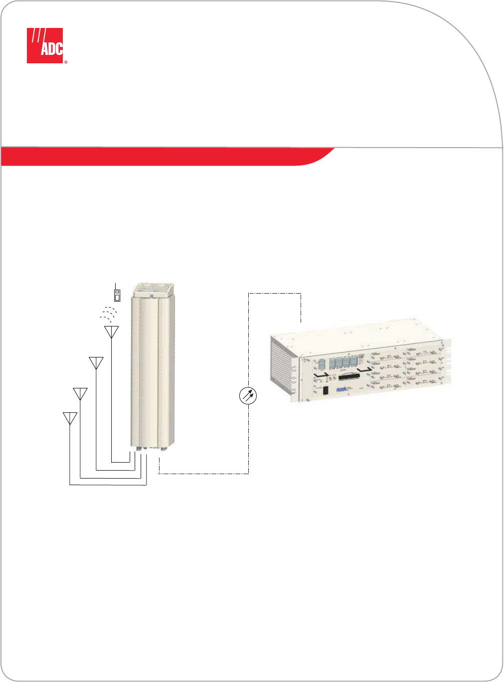
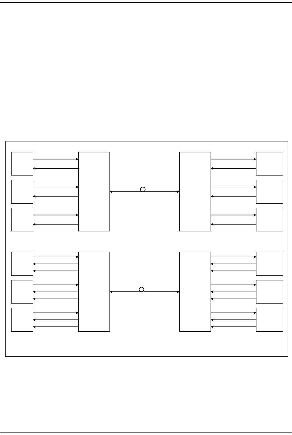
Figure 1-1. Multiple Point-to-Point Configuration
(One Band per Remote, Three Nodes)
Host Unit
Antenna
Band A
Sector Y
Antenna
Band A
Sector B
Antenna
Band A
Sector A
Remote Unit
Remote Unit
Remote Unit
77073-002
RF
Base
Transceiver
Stations
Band A
Sector Y
Band A
Sector B
Band A
Sector A
RF
RF
FlexWave Prism System
Page 8 FlexWave Prism Host, Remote and EMS 5.1 System Reference
© 2009 ADC Telecommunications, Inc ADCP-77-073 • Issue 2 • 11/2009
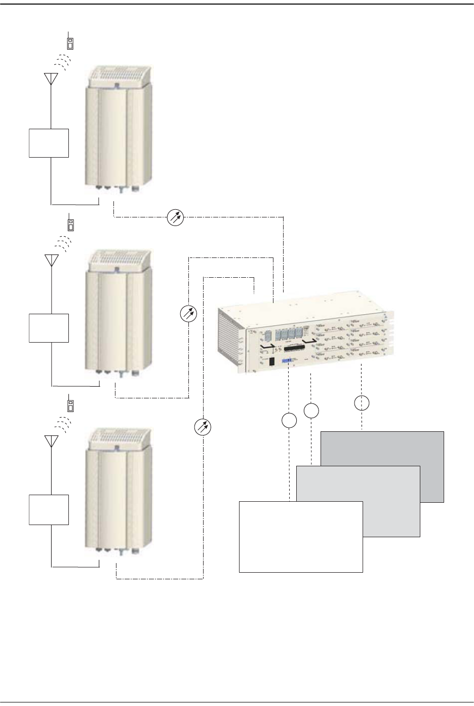
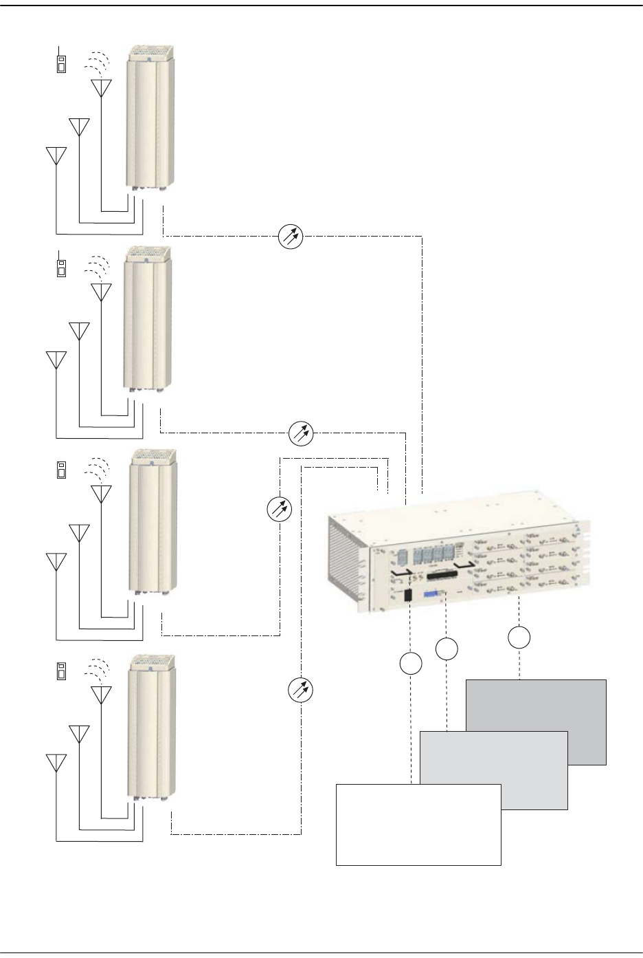
Figure 1-2. Four Remote Simulcast, Three Bands
Host Unit
Antenna
Band A
Antenna
Band B
Antenna
Band C
Antenna
Band A
Antenna
Band B
Antenna
Band C
Antenna
Band A
Antenna
Band B
Antenna
Band C
Antenna
Band A
Antenna
Band B
Antenna
Band C
Tri-Band
Remote
Base
Transceiver
Stations
Band C
Band B
Band A
RF
RF
RF
77073-003
Tri-Band
Remote
Tri-Band
Remote
Tri-Band
Remote
Basic System Components
FlexWave Prism Host, Remote and EMS 5.1 System Reference Page 9
ADCP-77-073 • Issue 2 • 11/2009 © 2009 ADC Telecommunications, Inc.
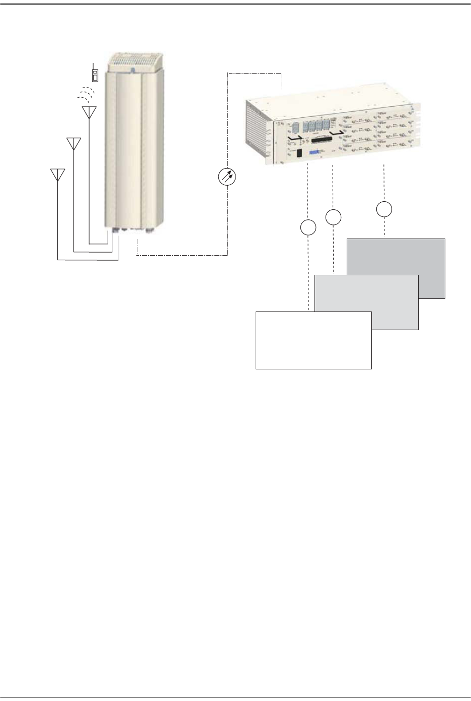
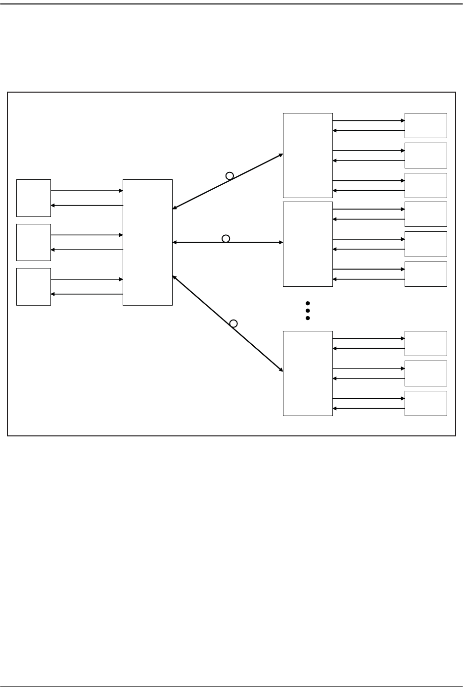
Figure 1-3. Three Bands to One Remote
Antenna
Band A
Antenna
Band B
Antenna
Band C
Host Unit
Tri-Band
Remote Unit
Base
Transceiver
Stations
Band C
Band B
Band A
RF
RF
RF
77073-004

FlexWave Prism System
Page 10 FlexWave Prism Host, Remote and EMS 5.1 System Reference
© 2009 ADC Telecommunications, Inc ADCP-77-073 • Issue 2 • 11/2009
1.3 MULTI-HOST SYSTEMS
ADC’s FlexWave Prism provides a Multi-Host feature that allows a Prism Remote to be
shared by multiple Host Units. To accomplish this:
•• One Host is designated as the IP Manager for a set of Remotes; this Host can serve
as IP manager for multiple Remotes. As the IP Manager, the managing Host
controls the exchange of management data with the Remote(s).
•• There is no Host to Host connectivity.
•• A Prism Remote can receive bands over multiple fibers that originate on different
Hosts. However, only one Host, the IP Manager, can manage the Remote. If a Host
attempts to manage a Remote already under the management of an IP Manager,
the second Host causes an IP Conflict fault (see “Viewing Host SeRF Optical Ports”
on page 224).
•• All the Hosts in a Multi-Host network can be configured to serve as clock master.
Each Host will be configured with a priority level in the range of
0
-
15
. The Host
with the priority level of
1
distributes the clock in the network. If the Host
designated as clock master fails or shuts down, the Host with the next highest
priority level takes over. (For information on setting the master clock, see “Set the
Clock Priority Level” on page 150.)
•• The FlexWave EMS provides a
Linking Mode
parameter that can be set to
Automated
or
Manual
for each Host. The
Linking Mode
is applicable for all Remotes connected
to the IP Manager. A Multi-Host system requires that the
Linking Mode
be set to
Manual
(see “(Optional) Configuring Multi-Host Systems for Manual Mode” on
page 168.
•• The Host that manages the Remote must be able to provision one or more
passbands on that Remote for which the Host does not have a DART card. Remote
DARTs are linked back to one or more Hosts in a Multi-Host system.
Multi-Host Systems
FlexWave Prism Host, Remote and EMS 5.1 System Reference Page 11
ADCP-77-073 • Issue 2 • 11/2009 © 2009 ADC Telecommunications, Inc.
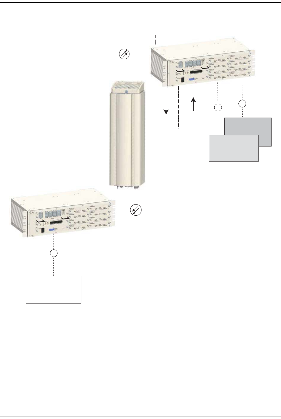
Figure 1-4. Multi-Host System
Tri-Band
Remote
Base
Transceiver
Stations
Band B
Band A
RF
RF
GET SET
(Host that manages the Remote)
Host 1 Location A
Host 2 Location B
77073-022
Base
Transceiver
Station
Band C
RF

FlexWave Prism System
Page 12 FlexWave Prism Host, Remote and EMS 5.1 System Reference
© 2009 ADC Telecommunications, Inc ADCP-77-073 • Issue 2 • 11/2009
1.4 DART CARDS
Digital/Analog Radio Transceiver (DART) cards provide the interface between base
station equipment and the SeRF. There are three types of FlexWave DART cards:
•• Classic
•• Single SuperDART
•• Dual SuperDART.
FlexWave DARTS are band specific assemblies available in the versions listed in
Table 1-1.
DART cards:
•• amplify, down-convert, filter and digitize the incoming RF signal from the BTS
•• convert incoming digital signal from the Remote to analog, filter, amplify and
up-convert the frequency from Intermediate Frequency (IF) to RF
•• provide a bi-directional interface between parallel digital RF (to D/A and from
A/D) and Serial RF (SeRF) to/from SeRF board
•• perform adjustable delay processing.
Table 1-1. FlexWave DART Card Types
Band Maximum
Bandwidth
(MHz)
Number of
Fiber Slots
Slot
Requirement
Classic DART Cards
AWS 2100 35 6 Single
Cell 850 35 6 Single
PCS 1900 35 6 Single
SMR 800 35 6 Single
SMR 900 35 6 Single
Single SuperDART Cards
GSM 900 35 6 Single
Dual SuperDART Cards
AWS 2100 45 8 Dual
GSM 1800 75 12 Dual
PCS 1900 70 12 Dual
UMTS 2100 60 12 Dual
DART Cards
FlexWave Prism Host, Remote and EMS 5.1 System Reference Page 13
ADCP-77-073 • Issue 2 • 11/2009 © 2009 ADC Telecommunications, Inc.
1.4.1 DARTs and Host Units
The Host can support up to eight Classic DARTS and/or Single SuperDARTs or up to
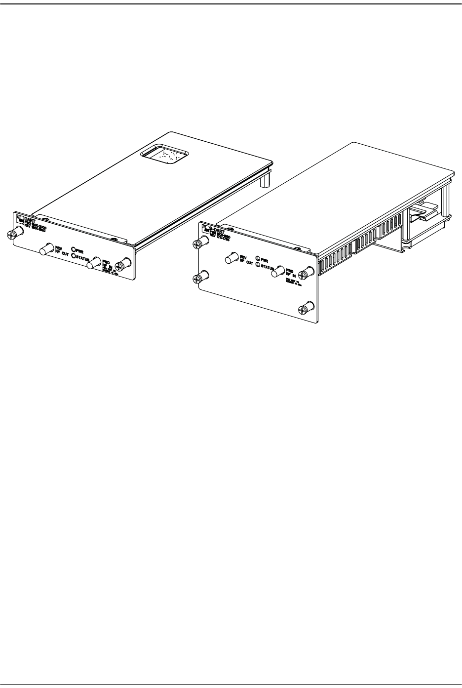
four Dual SuperDARTs. Figure 1-5 provides generic representations of Classic DARTS
or Single SuperDARTs and Dual SuperDARTs.
Figure 1-5. DART Cards
Generic representation of a
Classic DART or Single SuperDART
Genreic representation of a
Dual SuperDART
77073-076
FlexWave Prism System
Page 14 FlexWave Prism Host, Remote and EMS 5.1 System Reference
© 2009 ADC Telecommunications, Inc ADCP-77-073 • Issue 2 • 11/2009
Figure 1-6 shows the possible slot assignments for Single and Dual SuperDARTs, and
where slot-divider bars are located.
•• A Classic DART or Single SuperDART can be installed in each of the eight slots in
the Host.
•• Dual SuperDARTs occupy two slots (1/3, 2/4, 5/7 or 6/8).
•• Dual SuperDARTs cannot occupy slot combinations 3/5 or 4/6.
•• Any combination of DARTs may be installed.
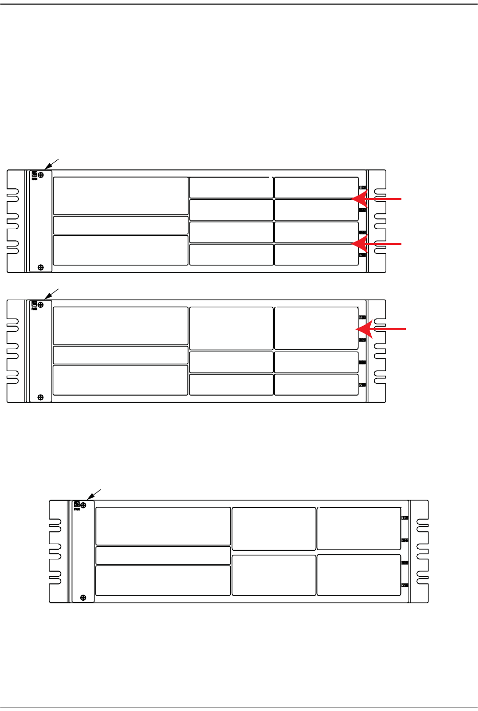
Figure 1-6. DART Slot Assignments in Host Chassis
Figure 1-7 shows a Host that is fully loaded with Dual SuperDART cards.
Figure 1-7. Host with Dual SuperDARTs
SeRF Card
System Card
Power Supply
Single-Slot DART
in Slot 1
Single-Slot DART
in Slot 3
Single-Slot DART
in Slot 2
Single-Slot DART
in Slot 4
Single-Slot DART
in Slot 7
Single-Slot DART
in Slot 5
Single-Slot DART
in Slot 8
Single-Slot DART
in Slot 6
Fan Assembly
Divider bars between
Slots 1 and 3
and Slots 2 and 4
Divider bars between
Slots 5 and 7
and Slots 6 and 8
SeRF Card
System Card
Power Supply
Fan Assembly
77073-077
Dual-Slot DART
in Slots 1 and 3
Dual-Slot DART
in Slots 2 and 4
Single-Slot DART
in Slot 7
Single-Slot DART
in Slot 5
Single-Slot DART
in Slot 8
Single-Slot DART
in Slot 6
Divider bars between
Slots 1 and 3 and
Slots 2 and 4 removed
to accommodate
Dual-Slot DARTs
SeRF Card
System Card
Power Supply
Fan Assembly
Dual SuperDART
in Slots 1 and 3
Dual SuperDART
in Slots 2 And 4
Dual SuperDART
in Slots 5 And 7
Dual SuperDART
in Slots 6 And 8
77073-078

DART Cards
FlexWave Prism Host, Remote and EMS 5.1 System Reference Page 15
ADCP-77-073 • Issue 2 • 11/2009 © 2009 ADC Telecommunications, Inc.
1.4.2 DARTs and Remote Units
The Remote DARTs are encased in its RF Module. Each RF Module will have up to two
Classic DARTs or Single SuperDARTs, or one Dual SuperDART, and there can be up to:
•• one RF Module in a Single-Band chassis
•• two RF Modules in a Dual-Band chassis
•• three RF Modules in a Tri-Band chassis
•• four RF Modules in a Quad-Band chassis.
The Remote DART Interface cards (RDI) and the Remote SeRF interface board (RSI)
provide Remote SeRF and DART connectivity for the Prism high speed digital
connections. The configuration of the DART cards provide the RF spectrum.
Prism Remote RF Modules are not field serviceable. To replace a DART within a Prism
Remote, you must replace the RF Module.
FlexWave Prism System
Page 16 FlexWave Prism Host, Remote and EMS 5.1 System Reference
© 2009 ADC Telecommunications, Inc ADCP-77-073 • Issue 2 • 11/2009
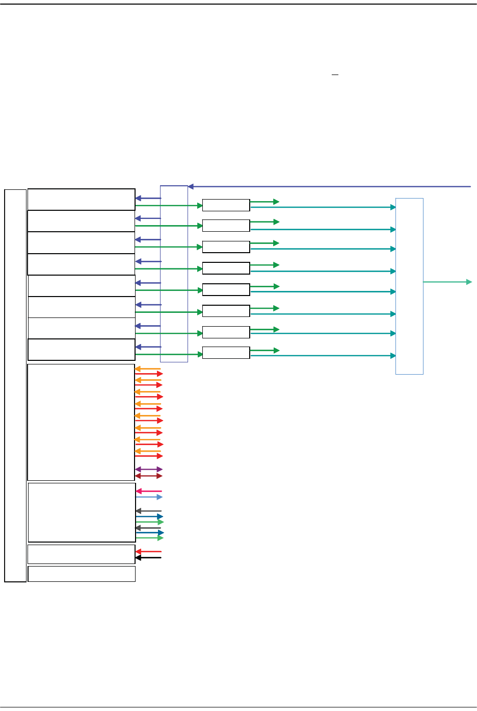
1.5 E911 SUPPORT
The DART type determines the maximum number of links, where there can be up to
8 DARTs for a 35MHz spectrum and up to 4 DARTs for a <75MHz spectrum.
E911 support may be achieved by using a configuration similar to the one shown in
Figure 1-8. Remote simulcasting in this configuration requires analog splitting and
combining to and from the individual Host DARTs. External analog
splitting/combining ensures that the E911 system receives uplink signals from each
Remote location before they are combined with uplink signals from the other
Remotes in the simulcast.
Figure 1-8. 8:1 Analog Simulcast U-TDoA E911 Support Diagram
2:1 Splitter
2:1 Splitter
2:1 Splitter
2:1 Splitter
2:1 Splitter
2:1 Splitter
2:1 Splitter
2:1 Splitter
8:18:1
DART BOARD (1)
DART BOARD (2)
DART BOARD (3)
DART BOARD (4)
DART BOARD (5)
DART BOARD (6)
DART BOARD (7)
DART BOARD (8)
SeRF BOARD
SYSTEM BOARD
POWER BOARD
FAN CARD
2:1 Splitter
2:1 Splitter
2:1 Splitter
2:1 Splitter
2:1 Splitter
2:1 Splitter
2:1 Splitter
2:1 Splitter
E911
E911
E911
E911
E911
E911
E911
E911
B
A
C
K
P
L
A
N
E
B
O
A
R
D
BTS REV
BTS FWD
77073-031
Fiber Optic Transport
FlexWave Prism Host, Remote and EMS 5.1 System Reference Page 17
ADCP-77-073 • Issue 2 • 11/2009 © 2009 ADC Telecommunications, Inc.
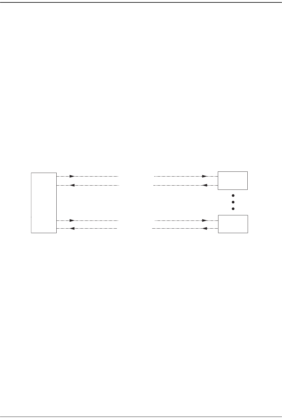
1.6 FIBER OPTIC TRANSPORT
In a typical Prism system the Host is connected to the Remote using two single-mode
optical fibers. One fiber is used to transport the forward pathh optical signal and a
second fiber is used to transport the reverse pathh optical signal. With the diversity
option, the diversity reverse pathh optical signal is sent on the same rev erse path
fiber. (However, the diversity signal can also be transmitted on a separate fiber pair
if more than 12 timeslots are required at a single Remote.) Because the optical signal
is digital, the input and output RF signal levels at the Host or the Remote are not
dependent on the level of the optical signal or the length of the optical fiber. A
diagram of the standard fiber optic transport system for both a non-diversity and
diversity system is shown in Figure 1-9.
The maximum length of the optical links is dependent on the loss specifications of
the optical fiber and the losses imposed by the various connectors and splices. The
system provides an optical budget of 25 dBB (typical) when used with 9/125
single-mode fiber. There must be at least 10 dB of optical loss to prevent over-driving
and possible damage to the optical receiver.
Figure 1-9. Standard Fiber Optic Transport Application
The SeRF (Serialized RF) digital protocol consists of digitized RF, Fast Ethernet, and
Host to Remote communication and management. The protocol provides you with
full access to the 100BASE-T (Ethernet) connection between the Host and each
Remote, and the ability to provision the RF spectrum of the DARTs. The digitized RF
portion of the SeRF protocol is divided into 12 timeslots, with each timeslot
representing roughly 5 MHz of digitized RF spectrum. Utilizing the full 12 timeslots
yields between 60 and 75 MHz of total digitized RF on each SeRF Small Form-Factor
Pluggable (SFP) laser connection.
77073-008
Remote
Unit
Forward Path
Reverse Path
Non-Diversity Fiber Optic Link
Forward Path
Diversity Fiber Optic Link
Reverse Path
And
Diversity Reverse Path
Host
Unit
Remote
Unit
Up To
Eight

FlexWave Prism System
Page 18 FlexWave Prism Host, Remote and EMS 5.1 System Reference
© 2009 ADC Telecommunications, Inc ADCP-77-073 • Issue 2 • 11/2009
The available RF bandwidth per timeslot is shown in Table 1-2.
For example, a user who wishes to transport PCS A block, Cellular A, and AWS B block,
the system would require the following:
PCS A 15MHz, 3 timeslots
Cellular A 10MHz, 2 timeslots
AWS B 10MHz, 2 timeslots
Total = 35MHz, 7 timeslots
Table 1-2. Available RF Bandwidth
Number
of
Timeslots
Maximum Contiguous
RF Bandwidth (MHz)
Classic
DARTs
Single and Dual
SuperDARTs
15 6
2 12.5 12
320 18
425 ---
635 39
8 --- 45
12 --- 60-75

Timeslots Versus Bandwidth
FlexWave Prism Host, Remote and EMS 5.1 System Reference Page 19
ADCP-77-073 • Issue 2 • 11/2009 © 2009 ADC Telecommunications, Inc.
1.7 TIMESLOTS VERSUS BANDWIDTH
Each fiber pair supports 12 timeslots, or up to 75 MHz of bandwidth. Table 1-2 shows
the maximum bandwidth versus the number of timeslots.
If more than 70 MHz is required per Remote, up to three additional fiber pairs can be
brought to the Remote to get up to up to 280MHz per Remote (or 300MHz if all four
are GSM-1800). This supports applications where there are two Classic DARTs or
Single SuperDARTs or one Dual SuperDART in a Remote RF Module.
The SeRF (Serialized RF) digital protocol consists of digitized RF, 100BASE-T Ethernet,
and Host to Remote communication and management. The protocol provides you
with full access to the 100BASE-T Ethernet connection between the Host and each
Remote, and the ability to provision the RF spectrum of the DARTs. The digitized RF
portion of the SeRF protocol is divided into 12 timeslots, with each timeslot
representing roughly 5 MHz of digitized RF spectrum. Utilizing the full 12 timeslots
yields between 60 and 80 MHz of total digitized RF on each SeRF SFP laser connection.

FlexWave Prism System
Page 20 FlexWave Prism Host, Remote and EMS 5.1 System Reference
© 2009 ADC Telecommunications, Inc ADCP-77-073 • Issue 2 • 11/2009
1.8 BANDWIDTHS
In the FlexWave Prism system, there are different Bandwidths from which to select,
ranging from 5 to 75 MHz. The different bandwidths allow you to configure the
system to use any contiguous or non-contiguous blocks within the 35 MHz of a single
Host 6-timeslot DART or 60-75 MHz using a 12-timeslot DART. DART bandwidth
options are shown in Table 1-3.
For DART cards, if you need to use non-contiguous blocks within a given 35 MHz,
then the selected bandwidth must span both of these blocks, even if the blocks in
between are not used. For example, if you want to use both PCS DD and EE blocks, select
PCS D+B+E
, which spans 25 MHz. This allows both PCS DD & EE to be transported and
the BB block is effectively unused.
PCS D and E are only 10 MHz of spectrum, four timeslots are required since the actual
transported spectrum is 25 MHz for the PCS D, B, E block, as shown in Table 1-3.
Table 1-3. DART Bandwidths
Band
Down- Link RF Band
(MHz)
Up- Link RF Band
(MHz)
Bandwidth Slots
(MHz)
Start Stop Start Stop Bandwidth
in MHz
# of
Timeslots
AWS A 2110 2120 1710 1720 10 2
AWS A+B 2110 2130 1710 1730 20 3
AWS A+B+C 2110 2135 1710 1735 25 4
AWS A+B+C+D 2110 2140 1710 1740 30 6
AWS A+B+C+D+E 2110 2145 1710 1745 35 6
AWS B 2120 2130 1720 1730 10 2
AWS B+C 2120 2135 1720 1735 15 3
AWS B+C+D 2120 2140 1720 1740 20 3
AWS B+C+D+E 2120 2145 1720 1745 25 4
AWS B+C+D+E+F 2120 2155 1720 1755 35 6
AWS C 2130 2135 1730 1735 5 1
AWS C+D 2130 2140 1730 1740 10 2
AWS C+D+E 2130 2145 1730 1745 15 3
AWS C+D+E+F 2130 2155 1730 1755 25 4
AWS D 2135 2140 1735 1740 5 1
AWS D+E 2135 2145 1735 1745 10 2
AWS D+E+F 2135 2155 1735 1755 20 3
AWS E 2140 2145 1740 1745 5 1
AWS E+F 2140 2155 1740 1755 15 3
AWS F 2145 2155 1745 1755 10 2
AWS 2100 2110 2155 1710 1755 45 8
AWS H 1995 2000 1915 1920 5 1
Cellular A 870 880 825 835 10 2

Bandwidths
FlexWave Prism Host, Remote and EMS 5.1 System Reference Page 21
ADCP-77-073 • Issue 2 • 11/2009 © 2009 ADC Telecommunications, Inc.
Cellular A' 890 891.5 845 846.5 1.5 1
Cellular A''+A 869 880 824 835 11 2
Cellular A''+A+A' 869 891.5 824 846.5 22.5 4
Cellular A''+A+B+A'+B' 869 894 824 849 25 4
Cellular B 880 890 835 845 10 2
Cellular B' 891.5 894 846.5 849 2.5 1
Cellular B+B' 880 894 835 849 14 3
GSM 1800 FullBand 1805 1880 1710 1785 75 12
GSM 900 FullBand 921 960 876 915 39 6
PCS A 1930 1950 1850 1865 20 3
PCS A+D 1930 1950 1850 1870 20 3
PCS A+D+B 1930 1965 1850 1885 35 6
PCS A+D+B1 1930 1955 1850 1875 25 4
PCS A+D+B1+B2 1930 1960 1850 1880 30 6
PCS A1 1930 1935 1850 1855 5 1
PCS A1+A2 1930 1940 1850 1860 10 2
PCS A2 1935 1940 1855 1860 5 1
PCS A2+A3 1935 1945 1855 1865 10 2
PCS A2+A3+D 1935 1950 1855 1870 15 3
PCS A2+A3+D+B 1935 1965 1855 1885 30 6
PCS A2+A3+D+B+E 1935 1970 1855 1890 35 6
PCS A2+A3+D+B1 1935 1955 1855 1875 20 3
PCS A2+A3+D+B1+B2 1935 1960 1855 1880 25 4
PCS A3 1940 1945 1860 1865 5 1
PCS A3+D 1940 1950 1860 1870 10 2
PCS A3+D+B 1940 1965 1860 1885 25 4
PCS A3+D+B+E 1940 1970 1860 1890 30 6
PCS A3+D+B+E+F 1940 1975 1860 1895 35 6
PCS A3+D+B1 1940 1955 1860 1875 15 3
PCS A3+D+B1+B2 1940 1960 1860 1880 20 3
PCS B 1950 1965 1870 1885 15 3
PCS B+E 1950 1970 1870 1890 20 3
PCS B+E+F 1950 1975 1870 1895 25 4
PCS B+E+F+C3 1950 1980 1870 1900 30 6
PCS B+E+F+C3+C4 1950 1985 1870 1905 35 6
PCS B1 1950 1955 1870 1875 5 1
PCS B1+B2 1950 1960 1870 1880 10 2
PCS B2 1955 1960 1875 1880 5 1
PCS B2+B3 1955 1965 1875 1885 10 2
Table 1-3. DART Bandwidths (Cont.)
Band
Down- Link RF Band
(MHz)
Up- Link RF Band
(MHz)
Bandwidth Slots
(MHz)
Start Stop Start Stop Bandwidth
in MHz
# of
Timeslots

FlexWave Prism System
Page 22 FlexWave Prism Host, Remote and EMS 5.1 System Reference
© 2009 ADC Telecommunications, Inc ADCP-77-073 • Issue 2 • 11/2009
PCS B2+B3+E 1955 1970 1875 1890 15 3
PCS B2+B3+E+F 1955 1975 1875 1895 20 3
PCS B2+B3+E+F+C 1955 1990 1875 1910 35 6
PCS B2+B3+E+F+C2 1955 1982.5 1875 1902.5 27.5 6
PCS B2+B3+E+F+C3 1955 1980 1875 1900 25 4
PCS B2+B3+E+F+C3+C4 1955 1985 1875 1905 30 6
PCS B3 1960 1965 1880 1885 5 1
PCS B3+E 1960 1970 1880 1890 10 2
PCS B3+E+F 1960 1975 1880 1895 15 3
PCS B3+E+F+C 1960 1990 1880 1910 30 6
PCS B3+E+F+C + SMR G 1960 1995 1880 1915 35 6
PCS B3+E+F+C2 1960 1982.5 1880 1902.5 22.5 4
PCS B3+E+F+C3 1960 1980 1880 1900 20 3
PCS B3+E+F+C3+C4 1960 1985 1880 1905 25 4
PCS C 1975 1990 1895 1910 15 3
PCS C + SMR G 1975 1995 1895 1915 20 3
PCS C + SMR G + AWS H 1975 2000 1895 1920 25 4
PCS C1 1982.5 1990 1902.5 1910 7.5 2
PCS C1 + SMR G 1982.5 1995 1902.5 1915 12.5 2
PCS C1 + SMR G + AWS H 1982.5 2000 1902.5 1920 17.5 3
PCS C2 1975 1982.5 1895 1902.5 7.5 2
PCS C3 1975 1980 1895 1900 5 1
PCS C3+C4 1975 1985 1895 1905 10 2
PCS C4 1980 1985 1900 1905 5 1
PCS C4+C5 1980 1990 1900 1910 10 2
PCS C4+C5 + SMR G 1980 1995 1900 1915 15 3
PCS C4+C5 + SMR G + AWS H 1980 2000 1900 1920 20 3
PCS C5 1985 1990 1905 1910 5 1
PCS C5 + SMR G 1985 1995 1905 1915 10 2
PCS C5 + SMR G + AWS H 1985 2000 1905 1920 15 3
PCS D 1945 1950 1865 1870 5 1
PCS D+B 1945 1965 1865 1885 20 3
PCS D+B+E 1945 1970 1865 1890 25 4
PCS D+B+E+F 1945 1975 1865 1895 30 6
PCS D+B+E+F+C3 1945 1980 1865 1900 35 6
PCS D+B1 1945 1955 1865 1875 10 2
PCS D+B1+B2 1945 1960 1865 1880 15 3
PCS E 1965 1970 1885 1890 5 1
PCS E+F 1965 1975 1885 1895 10 2
Table 1-3. DART Bandwidths (Cont.)
Band
Down- Link RF Band
(MHz)
Up- Link RF Band
(MHz)
Bandwidth Slots
(MHz)
Start Stop Start Stop Bandwidth
in MHz
# of
Timeslots

Bandwidths
FlexWave Prism Host, Remote and EMS 5.1 System Reference Page 23
ADCP-77-073 • Issue 2 • 11/2009 © 2009 ADC Telecommunications, Inc.
PCS E+F+C 1965 1990 1885 1910 25 4
PCS E+F+C + SMR G 1965 1995 1885 1915 30 6
PCS E+F+C + SMR G +AWS H 1965 2000 1885 1920 35 6
PCS E+F+C2 1965 1982.5 1885 1902.5 17.5 3
PCS E+F+C3 1965 1980 1885 1900 15 3
PCS E+F+C3+C4 1965 1985 1885 1905 20 3
PCS F 1970 1975 1890 1895 5 1
PCS F+C 1970 1990 1890 1910 20 3
PCS F+C + SMR G 1970 1995 1890 1915 25 4
PCS F+C + SMR G + AWS H 1970 2000 1890 1920 30 6
PCS F+C2 1970 1982.5 1890 1902.5 12.5 2
PCS F+C3 1970 1980 1890 1900 10 2
PCS F+C3+C4 1970 1985 1890 1905 15 3
PCS FullBand 1930 2000 1850 1920 70 12
SMR 851-869 (SMR Low Wide) 851 869 806 824 18 3
SMR 863-869 (SMR Low) 863 869 818 824 6 2
SMR 935-940 (SMR High) 935 940 896 901 5 1
SMR G 1990 1995 1910 1915 5 1
SMR G + AWS H 1990 2000 1910 1920 10 2
UMTS 2100 2110 2170 1920 1980 60 12
Table 1-3. DART Bandwidths (Cont.)
Band
Down- Link RF Band
(MHz)
Up- Link RF Band
(MHz)
Bandwidth Slots
(MHz)
Start Stop Start Stop Bandwidth
in MHz
# of
Timeslots
FlexWave Prism System
Page 24 FlexWave Prism Host, Remote and EMS 5.1 System Reference
© 2009 ADC Telecommunications, Inc ADCP-77-073 • Issue 2 • 11/2009
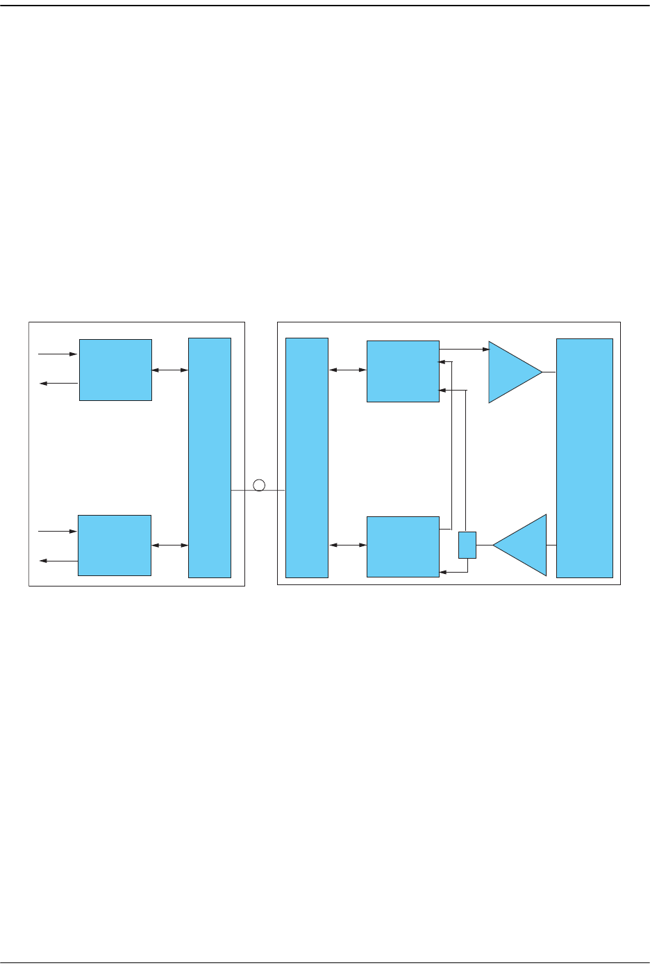
1.9 AWS AND PCS BAND OPTIONS
The Dual-AWS and Dual-PCS DARTs allow you to span non-contiguous bands:
•• the Dual-AWS DART comprises two 6-Timeslot AWS DARTs that span the full 45
MHz of the AWS band
•• the Dual-PCS DART provides two PCS blocks over the entire 70 MHz PCS
spectrum.
In the forward path, the two Remote DARTs are summed together before being sent
to the Linear Power Amplifier (LPA). In the reverse direction, the Low Noise Amplifier
(LNA) is split providing the full PCS or AWS spectrum to each DART. Each DART is
responsible for transporting its own spectrum, as shown in an the following example
for a PCS configuration.
Prism Host Prism Remote
PCS
DART
PCS
DART
TX
RX
TX
RX
PCS
DART
PCS
DART
LPA
PCS
Duplexor
Duplexer/
LNA
+
SeRF SeRF
77073-028

AWS and PCS Band Options
FlexWave Prism Host, Remote and EMS 5.1 System Reference Page 25
ADCP-77-073 • Issue 2 • 11/2009 © 2009 ADC Telecommunications, Inc.
PCS Configuration Example:
If the application requires both the A and C block, in the Remote the forward path of
the PCS A band is combined with the forward path of the PCS C band and these
signals are sent to the LPA to be amplified. In the reverse direction, the Duplexer/LNA
passes/amplifies the entire PCS band. The first DART digitizes the PCS A block
reverse path and the second DART digitizes the PCS C block reverse path and then
sends them back to the Host to be reconstructed back into RF.
The installer needs to provide the separate connections at the Host location either by
splitting already combined signals to/from each DART, or by providing them
independently.
If the two PCS reverse path blocks are combined at the Host location, then they must be
separated by at least 5 MHz to insure that the reverse paths do not interfere with each
other during the re- combining.

FlexWave Prism System
Page 26 FlexWave Prism Host, Remote and EMS 5.1 System Reference
© 2009 ADC Telecommunications, Inc ADCP-77-073 • Issue 2 • 11/2009
Intentionally Blank Page

FlexWave Prism Host, Remote and EMS 5.1 System Reference Page 27
ADCP-77-073 • Issue 2 • 11/2009 ©2009 ADC Telecommunications, Inc.
2PRISM SYSTEM COMPONENTS
2.1 FlexWave Prism Family Overview......................................................................... 28
2.2 FlexWave Prism Host Units ................................................................................. 30
2.2.1 Host Front Panel........................................................................................ 30
2.2.2 Host Network Connection............................................................................ 33
2.2.3 Host RF Signal Connections......................................................................... 33
2.2.4 Host System Card...................................................................................... 34
2.3 Prism Remote Units ........................................................................................... 35
2.3.1 Handset Interface...................................................................................... 36
2.3.2 Remote Components.................................................................................. 36
2.3.2.1 Remote RF Modules............................................................................ 38
2.3.2.1.1 Remote Duplexer and Low Noise Amplifier ..................................... 40
2.3.2.1.2 Linear Power Amplifiers............................................................... 41
2.3.2.2 Remote SeRF Modules ........................................................................ 43
2.3.2.3 Remote Power Supply and Cable Assembly............................................ 44
2.3.2.4 Solar Shield ...................................................................................... 45
2.3.2.5 Mounting Bracket (Remotes) ............................................................... 46
2.3.2.6 Remote Connectors............................................................................ 47
2.3.2.7 Remote Fiber Connector Cable Assembly............................................... 49
2.3.2.8 Remote Antenna Cable Connections ..................................................... 49
2.3.2.9 Remote Grounding ............................................................................. 49
2.3.2.10 Remote Cooling ............................................................................... 49
2.4 Prism System Accessories .................................................................................. 50
2.4.1 Lightning Surge Suppressor (Remote Accessory) ........................................... 50
2.4.2 Uninterruptible Power Supply (Accessory) ..................................................... 50
2.4.3 Wavelength Division Multiplexer System (Accessory)...................................... 50
2.4.4 Course Wavelength Division Multiplexer System (Accessory) ........................... 51
2.4.5 Millimeter Wave Systems (Accessory)........................................................... 55
2.5 Prism System Specifications ............................................................................... 56
2.5.1 Host Unit Specifications .............................................................................. 56
2.5.2 Remote Unit Specifications.......................................................................... 57
2.5.3 System Nominal Optical Specifications.......................................................... 58
Content Page
Prism System Components
Page 28 FlexWave Prism Host, Remote and EMS 5.1 System Reference
© 2009 ADC Telecommunications, Inc ADCP-77-073 • Issue 2 • 11/2009
2.1 FLEXWAVE PRISM FAMILY OVERVIEW
The ADC FlexWave Prism family of products is a Distributed Antenna System (DAS)
that provides ADC’s patented technology—bidirectional transport of digitized RF
spectrum over fiber. The high-speed digitalization of a wideband portion of spectrum
allows for transport of RF signals over extended distances, without the RF
degradation that normally results when analog systems are impacted by optical
effects. The basic function of the FlexWave Prism platform is to transport via fiber
optic cable RF signals from a Base Transceiver Station (BTS) to an antenna interface
allowing communication to a mobile device. Multiple BTS communication paths are
allowed over a single Prism system. Each link consists of a Host that provides the
interface between the base station RF ports and the optical fiber, and at least one
Remote that provides the interface between the optical fiber and the remote antenna.
A block diagram of the system is shown in Figure 2-1.
Figure 2-1. FlexWave Tri-Band Prism Block Diagram
FlexWave
Host
FWD RF IN
REV RF OUT
BTS 1
Antenna
Interface
BTS 1
BTS 2
BTS 3
Antenna
Interface
BTS 2
Antenna
Interface
BTS 3
NON-DIVERSITY
FWD RF IN
REV RF OUT
BTS 1
Antenna
Interface
BTS 1
BTS 2
BTS 3
Antenna
Interface
BTS 2
Antenna
Interface
BTS 3
DIVERSITY
REV DIV RF OUT
FWD RF OUT
REV RF IN
REV DIV RF IN
FWD RF OUT
REV RF IN
REV DIV RF IN
FWD RF OUT
REV RF IN
REV DIV RF IN
FWD RF IN
REV RF OUT
REV DIV RF OUT
FWD RF IN
REV RF OUT
REV DIV RF OUT
FWD RF IN
REV RF OUT
FWD RF IN
REV RF OUT
FWD RF OUT
REV RF IN
FWD RF OUT
REV RF IN
FWD RF OUT
REV RF IN
FlexWave
Host
FlexWave
Remote
FlexWave
Remote
77073-005
FlexWave Prism Family Overview
FlexWave Prism Host, Remote and EMS 5.1 System Reference Page 29
ADCP-77-073 • Issue 2 • 11/2009 © 2009 ADC Telecommunications, Inc.
The basic function of FlexWave Prism simulcast (point-to-multipoint) is to transport,
via fiber optic cable, RF signals from a Base Transceiver Station (BTS) to multiple
antenna interfaces allowing communication to a mobile device (see Figure 2-2). Up to
8 simulcast Remotes are supported.
Figure 2-2. System Block Diagram for Eight-Way Simulcast
FlexWave
Host
FWD RF IN
REV RF OUT
BTS 1
BTS 2
BTS 3
FWD RF IN
REV RF OUT
FWD RF IN
REV RF OUT
FlexWave
Remote 1
Antenna
Interface
BTS 1
FWD RF OUT
REV RF IN
FWD RF OUT
REV RF IN
FWD RF OUT
REV RF IN
FWD RF OUT
REV RF IN
FWD RF OUT
REV RF IN
FWD RF OUT
REV RF IN
FWD RF OUT
REV RF IN
FWD RF OUT
REV RF IN
FWD RF OUT
REV RF IN
FlexWave
Remote 2
FlexWave
Remote 8
Antenna
Interface
BTS 1
Antenna
Interface
BTS 1
Antenna
Interface
BTS 1
Antenna
Interface
BTS 1
Antenna
Interface
BTS 1
Antenna
Interface
BTS 1
Antenna
Interface
BTS 1
Antenna
Interface
BTS 1
77073-006

Prism System Components
Page 30 FlexWave Prism Host, Remote and EMS 5.1 System Reference
© 2009 ADC Telecommunications, Inc ADCP-77-073 • Issue 2 • 11/2009
2.2 FLEXWAVE PRISM HOST UNITS
The Host is designed for maximum RF flexibility to address Carriers’ changing and
evolving spectrum needs, making the most use of cost efficient resources for serving
multiple remotes such as simulcast architecture and sharing of common functions
such as power, control and management over multiple Hosts. Each Host may be
interfaced with one or more Base Transceiver Station (BTS). Each BTS provides the RF
channel inputs and outputs for a designated sector.
The Host is designed as a compact package that reduces rack space required within
a BTS Hotel. The Host is a three rack-unit high single-unit assembly that mounts in a
standard 19- or 23-inch equipment rack. Its front access interfaces with the BTS for
transport to subtended Remotes, and performs the analog to digital and electrical to
optical conversions for transport to a Host and subtended Remotes. Each Host can
support up to eight Remotes. The Remote is a modular self-contained outdoor
enclosure that houses various electronic components.
2.2.1 Host Front Panel.
The Host is designed for use within a non-condensing indoor environment such as
inside a wiring closet or controlled environment cabinet. All controls, connectors, and
indicators (except the grounding point) are mounted on the Host front panel and
allows vertical cable guides to be installed over the mounting brackets on either side.
The Host user interface on its front panel comprises the connectors, switches,
terminals, and LEDs that are described in Figure 2-3 and Table 2-1.
The Host can be mounted in either a 19- inch or 23- inch EIA or WECO equipment rack.
Unless noted otherwise, views of the Host in this document show the mounting
brackets in the 23- inch position. The default is the 19- inch position.
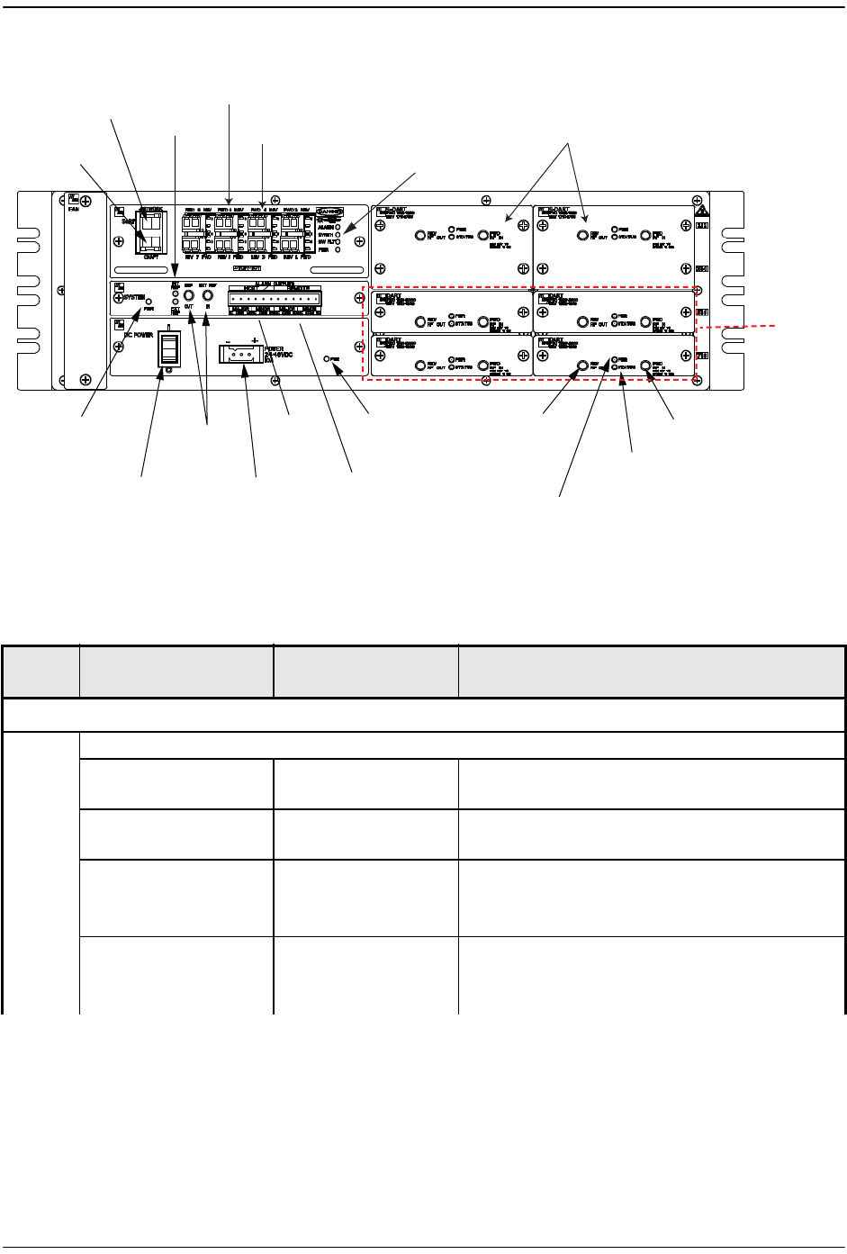
FlexWave Prism Host Units
FlexWave Prism Host, Remote and EMS 5.1 System Reference Page 31
ADCP-77-073 • Issue 2 • 11/2009 © 2009 ADC Telecommunications, Inc.
Figure 2-3. User Interface on Host Front Panel
Table 2-1. Host User Interface
Ref No User Interface
Designation
Device Functional Description
SeRF Card
1 SeRF Card LEDs
ALARM • ON
•OFF
• Initial bootup sequence
• System operation normal
SYNTH • GREEN
•RED
•Locked
•Unlocked
SW FLT • ON
•OFF
•RED
• Initial bootup sequence
• Software operating OK
• Software failed to start
PWR • GREEN
•RED
•OFF
• Power OK and operating properly
• Power supply out of tolerance
• No power present
(3) Optical Port
FWD & REV
Connectors 1 -8
(5) Craft
Interface
(4) Network
Interface (12) REF LED
Indicators
(1) SeRF CARD
ALARM LEDS
(9) System Card
Power LED
Indicator
(7) DC Power
ON/OFF Switch
(8) Power
Connector
(13 & 14)
REF OUT
& IN Jacks
(10) Host
Alarm
Outputs
(11) Remote
Alarm Outputs
(6) Power
LED Indicator (18) FWD RF
IN Jack
(16) DART Status
LED Indicator
(15) DART Power
LED Indicator
(17) REV RF
OUT Jack
(19) Two 12-Timeslot DARTs
(2) SFP RX
and TX LEDs
77073-032
(20) Four
6-Timeslot
DARTs

Prism System Components
Page 32 FlexWave Prism Host, Remote and EMS 5.1 System Reference
© 2009 ADC Telecommunications, Inc ADCP-77-073 • Issue 2 • 11/2009
2 SFP TX (LED) • OFF
• GREEN
•RED
• No Small Form-Factor Pluggable (SFP)
present
• SFP is present and the FPGA internal PLL is
locked
• SFP is present and the FPGA internal PLL is
not locked
SFP RX (LED) • OFF
• GREEN
•AMBER
• No Small Form-Factor Pluggable (SFP)
present
• Receiver has locked and framed to the
incoming signal
• Receiver has locked to the incoming
frequency, but there is no framing
information on the fiber
3 PORT 1–8 LC connector
(single-mode)
Input/output connection points for Ports 1
through 8 optical fibers. (FWD and REV)
4 NETWORK RJ-45 jack (female) Connection point for the NETWORK interface
5 CRAFT RJ-45 jack (female) Connection point for the CRAFT interface
POWER SUPPLY
6 PWR (LED) • GREEN
•RED
•DC Power Supply OK
•DC Power Supply Fault
7 ON/OFF On/Off rocker
switch
Provides Host power on/off control
8 POWER 20–60 Vdc Three position
connector
Connection point for the DC power wiring
SYSTEM CARD
9 PWR (LED) • GREEN
•RED
• System Card Power Supply OK
• System Card Power Supply Fault
10 ALARM OUTPUTS
HOST
Twelve position
terminal block.
Screw-type terminal
connector (14–26
AWG)
Connection points for a major and minor dry
alarm contacts. Includes normally open (NO),
normally closed (NC), and common (COM)
wiring connections
11 ALARM OUTPUTS
REMOTE
12 INT REF (LED) • GREEN
•OFF
• Internal 10 MHz reference selected as the
as Reference Clock.
• Internal 10 MHz reference not selected.
EXT REF (LED) • GREEN
•OFF
• External 10 MHz reference selected as the
as Reference Clock.
• External 10 MHz reference not selected
13 REF OUT QMA-Type female RF
coaxial connector
10 MHz reference clock output that may be
used to synchronize between multiple host
units.
14 EXT REF IN QMA-Type female RF
coaxial connector
10 MHz reference clock output that may be
used to synchronize between multiple host
units.
Table 2-1. Host User Interface (Cont.)
Ref No User Interface
Designation
Device Functional Description

FlexWave Prism Host Units
FlexWave Prism Host, Remote and EMS 5.1 System Reference Page 33
ADCP-77-073 • Issue 2 • 11/2009 © 2009 ADC Telecommunications, Inc.
2.2.2 Host Network Connection
The SeRF front panel has a Network port that creates a network connection between
the Host and the network to monitor and configure the FlexWave Prism system
through the FlexWave EMS.
The network interface connection between the Host and the network is supported by
a Gigabit Ethernet (10/100/1000) RJ-45 jack with integrated green ACTIVITY and
LINK LEDs. The Network port supports a maximum cable length of 100 meters (328
feet) to a switch or back-to-back nodes. CAT5 or better cable should be used when
making this connection. The Ethernet connection should not be connected to an
Ethernet circuit used outside the building.
For further information on using the Network port and the FlexWave EMS, see
“System Setup and Management.”
2.2.3 Host RF Signal Connections
The RF signal connections between the Host DART cards and the BTS are supported
through two (FWD RF IN and REV RF OUT) QMA-Type female connectors. One
connector is used for the forward path RF signal. The other connector is used for the
reverse path RF signal. In some installations, it may be necessary to install a
Conditioning Panel and/or Duplexing Panel (accessory items) to support the interface
between the Host and the BTS. The Host should be as close as possible to the BTS to
minimize cable losses.
DART CARD
15 PWR (LED) • GREEN
•OFF
• Card is powered.
• No power present at card.
16 STATUS (LED) • GREEN
•RED
• YELLOW
•OK
• Major Alarm
• ALC activated
17 REV RF OUT QMA-Type female RF
coaxial connector
Output connection point for the primary
reverse path RF coaxial cable
18 FWD RF IN QMA-Type female RF
coaxial connector
Input connection point for the forward path
RF coaxial cable
19 & 20 Slots 1 - 8 • Classic DARTs
•Single
SuperDARTs
• Dual SuperDARTs
• Classic DARTS and Single SuperDARTs can
occupy Slots 1 - 8 (usually a 6-Timeslot
DART)
• Dual SuperDARTs can occupy Slots 1/3,
5/7, 2/4 or 6/8 (12-Timeslot DARTs)
Table 2-1. Host User Interface (Cont.)
Ref No User Interface
Designation
Device Functional Description

Prism System Components
Page 34 FlexWave Prism Host, Remote and EMS 5.1 System Reference
© 2009 ADC Telecommunications, Inc ADCP-77-073 • Issue 2 • 11/2009
2.2.4 Host System Card
The System Card contains the fan controller, the clocking circuitry (internal or
external), the temperature sensor and the DCC contacts. Its front panel provides
connections for alarm outputs, 10 MHz output, and status LEDs. This card may be
used to provide a 10 MHz clock reference to which the SeRF's Master clock is
frequency locked from the internal crystal oscillator. When the internal clock is not
used the clock can be obtained from an external 10 MHz input.
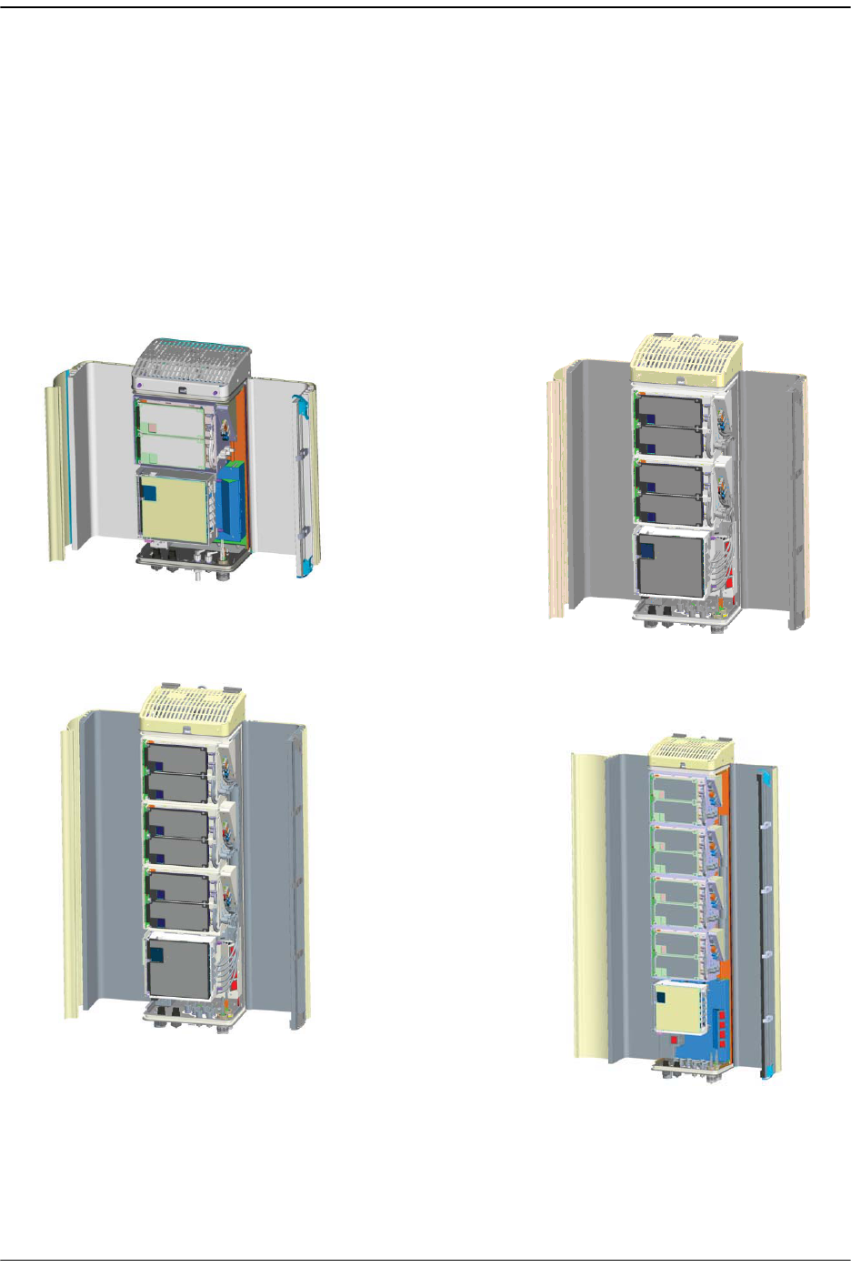
Prism Remote Units
FlexWave Prism Host, Remote and EMS 5.1 System Reference Page 35
ADCP-77-073 • Issue 2 • 11/2009 © 2009 ADC Telecommunications, Inc.
2.3 PRISM REMOTE UNITS
The Remote, shown in Figure 2-4, controls RF emissions, interfaces with the FlexWave
Host and performs the optical to electrical conversions for transport to the antennas.
The Remote is an environmentally-sealed unit that houses the electronic assemblies
such as the DART board and the Power Amplifier, and seals out dirt and moisture.
The Prism uses fans located on the top of each unit to cool the chassis. The antenna
cable connectors, fiber connectors, AC power connector, and the unit status indicator
are located on the bottom of the unit.
Figure 2-4. Prism Remote Units
Single-Band Remote Dual-Band Remote
Tri-Band Remote
Quad-Band Remote
77073-007

Prism System Components
Page 36 FlexWave Prism Host, Remote and EMS 5.1 System Reference
© 2009 ADC Telecommunications, Inc ADCP-77-073 • Issue 2 • 11/2009
The FlexWave Remote supports or provides the following basic functions:
•• Receives on the forward path the digitized spectrum from the Host and converts
the spectrum back into an RF signal to be distributed via an externally mounted
antenna system. On the reverse path, the Remote digitizes the designated RF
spectrum and digitally transports it over single mode fiber or Millimeter Wave
(MMW) to the Host.
•• Provides RF interface (antenna port) for the antennas.
•• Accepts AC power input.
2.3.1 Handset Interface
The Remote interfaces with the handsets (cell phones) through an antenna. In the
reverse path, the Remote receives RF signals from each handset (see Figure 1-3 on
page 9). The Remote digitizes the RF signals and then converts them to digital optical
signals for transport to the Host over the optical fiber link. In the forward path, the
Remote receives digital optical signals from the Host. The Remote converts the
optical signals to RF signals for transmission to the handsets.
2.3.2 Remote Components
Prism Remotes are shipped ready to accept easy to install RF Modules. The following
sections describe the Remote components listed below and shown in Figure 2-5.
•• RF Modules
•• SeRF Module
•• Remote SeRF interface board (RSI)
•• DART cards
•• Remote DART Interface (RDI) board
•• Power supply boards
•• Linear Power Amplifier (LPA)
•• Duplexer with a Low Noise Amplifier (LNA)
•• Solar shield
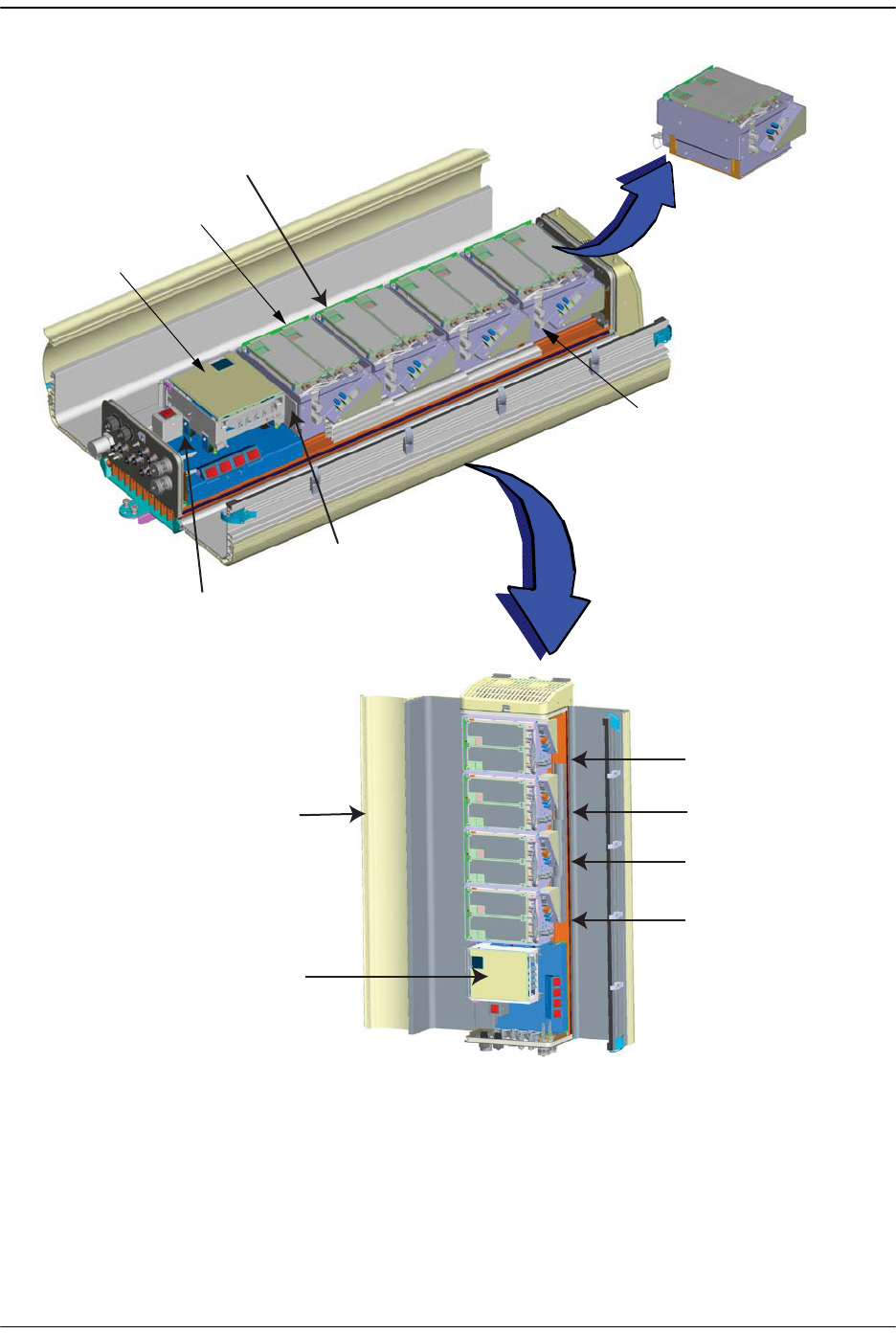
Prism Remote Units
FlexWave Prism Host, Remote and EMS 5.1 System Reference Page 37
ADCP-77-073 • Issue 2 • 11/2009 © 2009 ADC Telecommunications, Inc.
Figure 2-5. Prism Remote Components
SeRF
module
Duplexer
DART
card
Linear Power
Amplifier
(not shown)
Solar Shield
RF Module
(4 in this
Quad-Band Prism)
Remote DART
Interface (RDI)
Power Supply
(not shown)
SeRF module
Remote Slot MOD D
RF Module / Band D
Remote Slot MOD C
RF Module / Band C
Remote Slot MOD B
RF Module / Band B
Remote Slot MOD A
RF Module / Band A
77073-009
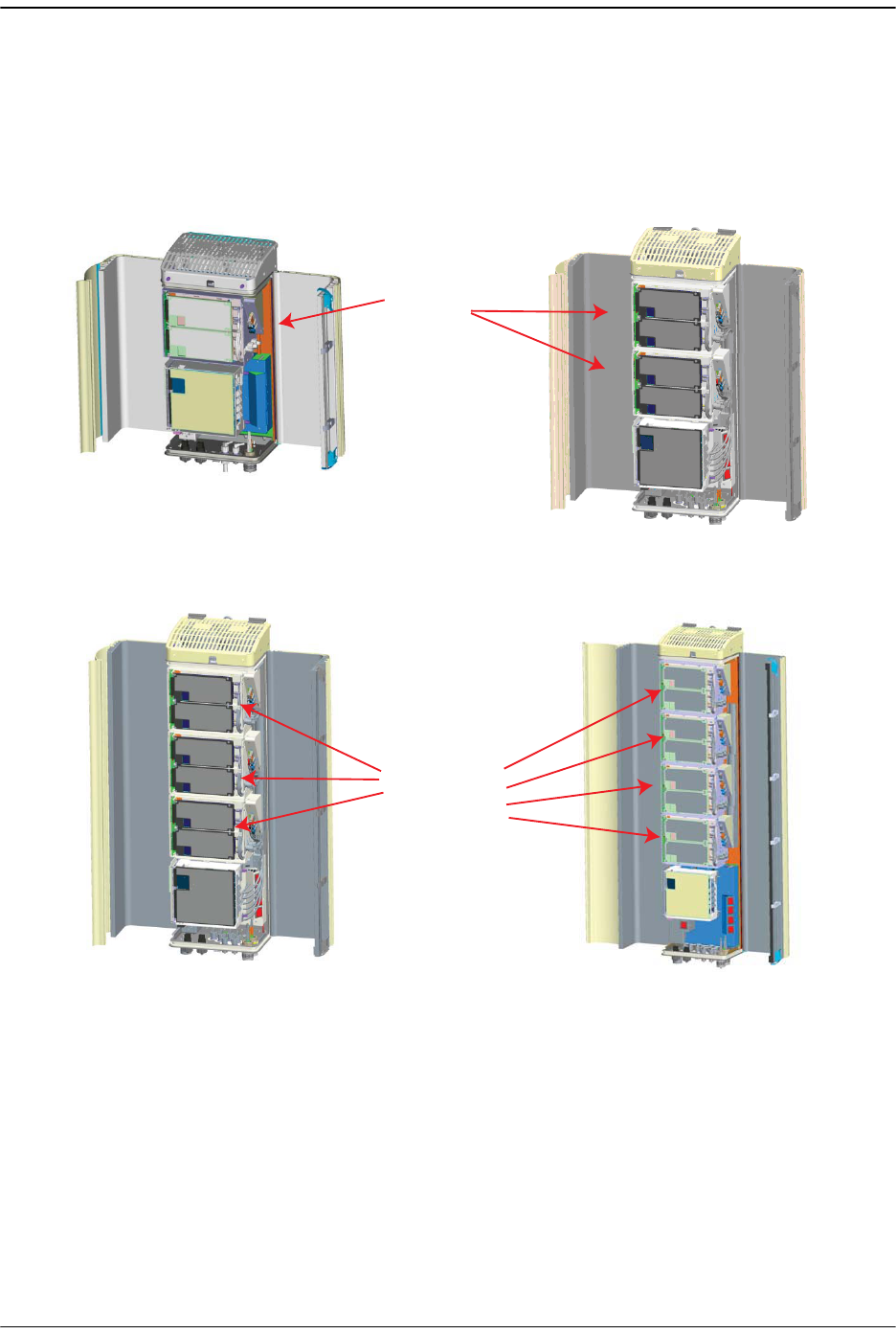
Prism System Components
Page 38 FlexWave Prism Host, Remote and EMS 5.1 System Reference
© 2009 ADC Telecommunications, Inc ADCP-77-073 • Issue 2 • 11/2009
2.3.2.1 Remote RF Modules
The Prism Remote comprises from 1 to 4 RF Module slots as shown in Figure 2-6.
Figure 2-6. RF Modules in Prism Remotes
Dual-Band Remote
with 2 RF module slots
Single-Band Remote
with 1 RF module slot
RF
module
slots
Tri-Band Remote
with 3 RF module slots
Quad-Band Remote
with 4 RF module slots
RF
module
slots
77073-019
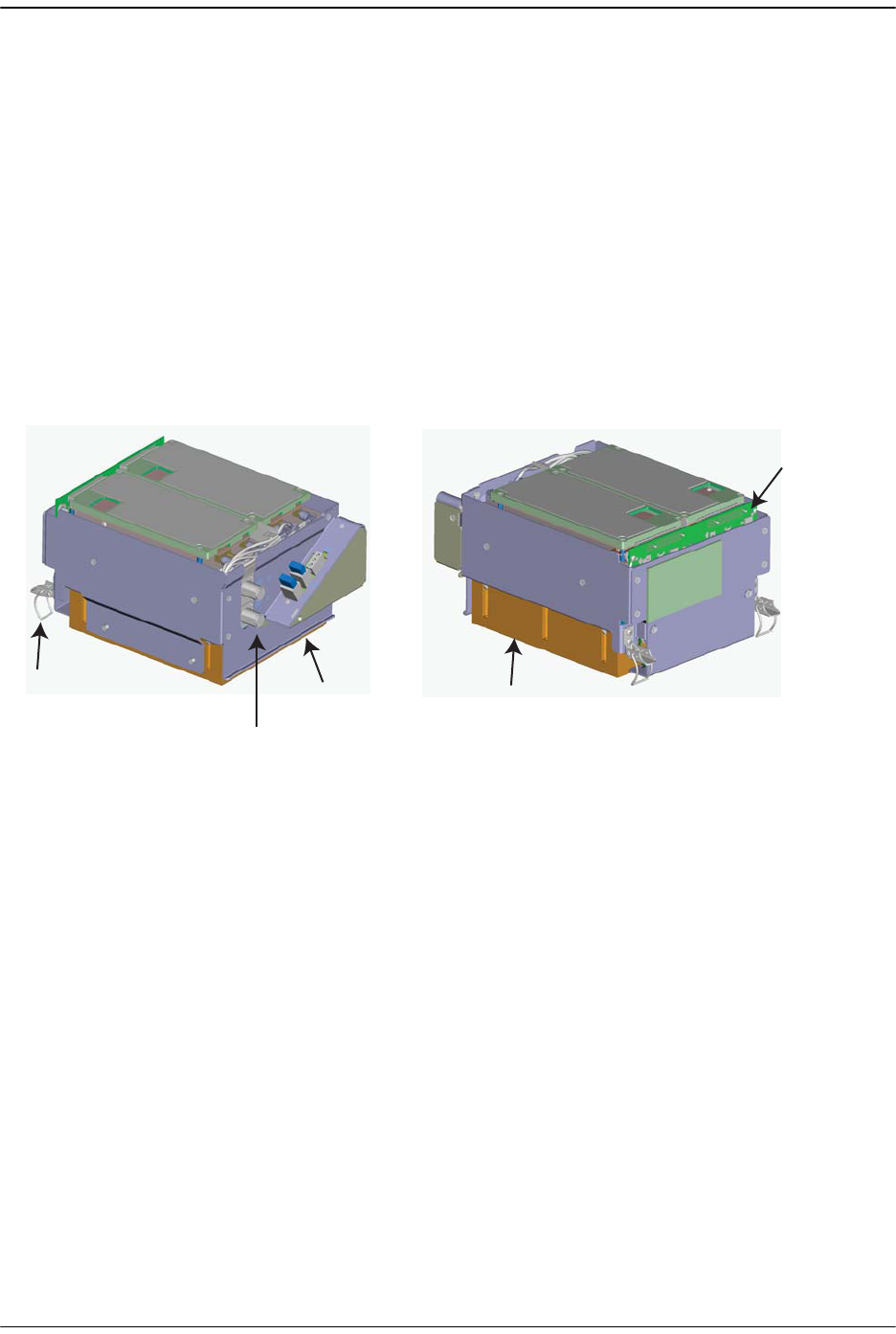
Prism Remote Units
FlexWave Prism Host, Remote and EMS 5.1 System Reference Page 39
ADCP-77-073 • Issue 2 • 11/2009 © 2009 ADC Telecommunications, Inc.
A Prism can support up to four RF Modules, dependent on the chassis size. Each RF
Module can comprise any of the following DART combinations:
•• one Classic DART or one Single SuperDART
•• two Classic DARTs
•• two Single SuperDARTs
•• one Classic DART and one Single SuperDART
•• one Dual SuperDART.
A Prism Remote can therefore comprise up to eight single-slot DARTS or up to four
Dual SuperDARTs, dependent on the Remote chassis size.
The Remote RF Modules are not field serviceable. To replace a DART card, you have
to replace the RF Module.
Figure 2-7. Remote RF Module
Mounting
latch Mounting
hook
Duplexer
Linear Power
Amplifier (LPA)
Remote DART
Interface (RDI)
77073-036
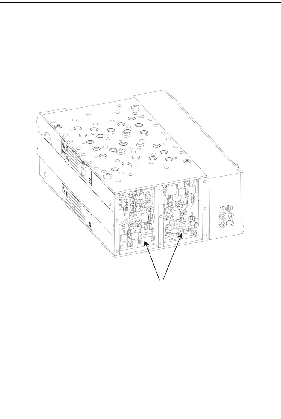
Prism System Components
Page 40 FlexWave Prism Host, Remote and EMS 5.1 System Reference
© 2009 ADC Telecommunications, Inc ADCP-77-073 • Issue 2 • 11/2009
2.3.2.1.1 Remote Duplexer and Low Noise Amplifier
The Remote has an internal Duplexer that is optimized to provide the desired RF
band-pass filtering and in-band equipment isolation between FWD and REV paths.
The Duplexer contains up to two REV path Low Noise Amplifiers (LNA for PRI and/or
SEC reverse paths). Each LNA (shown in Figure 2-8) is a high quality low noise
amplifier providing the Prism reverse path with nominal 30dB REV gain and system
NF of 5dB per RX path. The Duplexer and its LNA are housed in the RF Module, and
are not field servicable.
Figure 2-8. Remote Duplexer with Low Noise Amplifiers
Low Noise Ampliers in Duplexer
77073-050
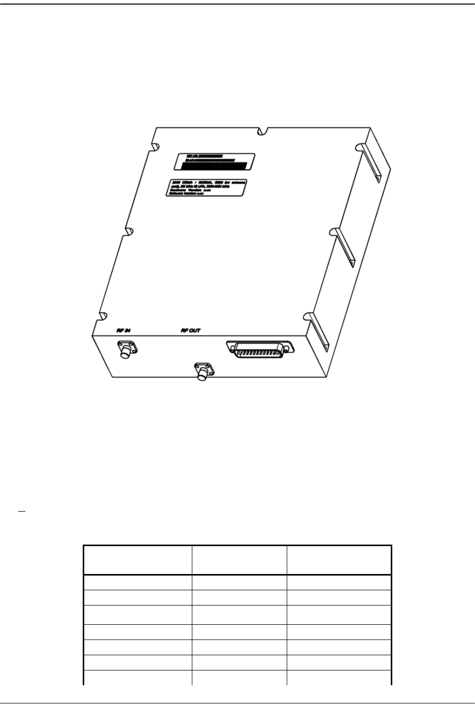
Prism Remote Units
FlexWave Prism Host, Remote and EMS 5.1 System Reference Page 41
ADCP-77-073 • Issue 2 • 11/2009 © 2009 ADC Telecommunications, Inc.
2.3.2.1.2 Linear Power Amplifiers
Figure 2-9 shows a Prism Linear Power Amplifier (LPA), which is a high quality
broadband RF amplifier used for achieving Prism product rated power for the Remote
Tx forward path spectrum RF.
Figure 2-9. Linear Power Amplifier
The FlexWave Prism Remote 40W RF Module is designed for AWS and PCS
frequencies. The Prism Remote 40W RF Module comprises one DART, two Linear
Power Amplifiers (LPAs), and one or two Remote DART Interface (RDI) boards (two
for a diversity module and one for a non-diversity module).
The LPAs are pass-band specific, with the maximum composite Tx power levels, and
>10dB instantaneous peak power rating listed in Table 2-2.
Table 2-2. LPA Maximum Composite Tx Power Levels
Passband* Maximum dBm
(WATT)
Instantaneous
Bandwidth
AWS +43dBm (20W) 45 MHz
AWS 2100 Dual-LPA +43dBm (20W) 45 MHz
Cellular +43dBm (20W) 25 MHz
EGSM 900 +40 dBm (10W) 39 MHz
GSM 1800/DCS +41 dBm (12.6W) 75 MHz
PCS +43dBm (20W) 70 MHz
PCS 1900 Dual-LPA +43dBm (20W) 70 MHz
75347-0006

Prism System Components
Page 42 FlexWave Prism Host, Remote and EMS 5.1 System Reference
© 2009 ADC Telecommunications, Inc ADCP-77-073 • Issue 2 • 11/2009
The LPA is housed within the Duplexer, and is not field serviceable.
SMR 800/900 +38dBm (6.5W) 18 MHz SMR800,
5 MHz SMR900
UMTS +42 dBm (15.8W) 60 MHz
* LPAs of the same passband can be combined to double the
output power or +3dBm.
Table 2-2. LPA Maximum Composite Tx Power Levels
Passband* Maximum dBm
(WATT)
Instantaneous
Bandwidth
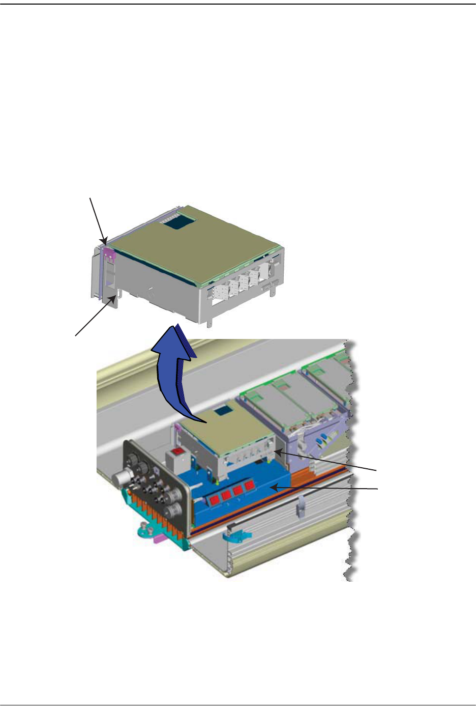
Prism Remote Units
FlexWave Prism Host, Remote and EMS 5.1 System Reference Page 43
ADCP-77-073 • Issue 2 • 11/2009 © 2009 ADC Telecommunications, Inc.
2.3.2.2 Remote SeRF Modules
The SeRF Module houses the SeRF board that supports:
•• eight SFP Fiber interfaces that run the SeRF protocol
•• eight DART Board interfaces
•• one crossbar multiplexer that splits, sums, and routes combinations of up to eight
DART links to a maximum of eight identical SeRF links
•• 10/100 Mbps ENET over fiber (up to 8 fibers)
•• hardware control of Remote under direction from the managing Host
Figure 2-10. Remote SeRF Module
SeRF Mounting Tab
(1 on each side)
Door Alarm
SeRF module
Power Supply
Bottom of
Remote Enclosure
77073-039
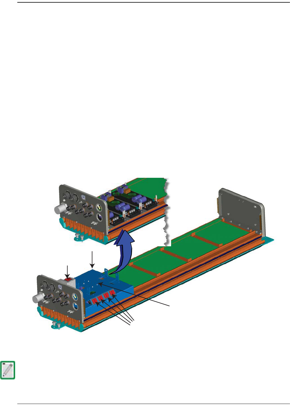
Prism System Components
Page 44 FlexWave Prism Host, Remote and EMS 5.1 System Reference
© 2009 ADC Telecommunications, Inc ADCP-77-073 • Issue 2 • 11/2009
2.3.2.3 Remote Power Supply and Cable Assembly
The Remote is powered by 100 to 240 VAC (nominal 120 or 240 VAC), 50 to 60 Hz
power. The AC power is supplied through a 15-foot (4.6m) three-wire power cable
that is provided with the unit. The power cable connects to a 3-pin AC power
connector mounted on the bottom of the Remote.
The stub end of the power cable must be routed to an external junction box (not
provided) for connection to the AC power source. A circuit breaker rated at 20 Amps
(120 VAC) should be used to provide over-current protection for the Prism power
circuit. It is also recommended that an external AC outlet (not provided) be installed
near the Remote to power test equipment and tools.
The Remote model determines the number of power supplies.
•• The Single-Band Remote is powered by one power supply.
•• The Dual-Band Remote is powered by two power supplies.
•• The Tri- and Quad-Band Remotes are powered by three power supplies.
There are up to four switches that independently control DC power for each RF
Module. These switches are labeled MOD A, MOD B, MOD C, and MOD D and
correspond to the RF Module shelves, from bottom to top, that are labeled the same.
Figure 2-11. Remote Power Supply
For further information on calculating required power, see “Power Consumption” on
page 129.
Power module
AC switch
for Remote
DC switches (4)
labeled MOD A - MOD D
for up to 4 RF Modules
Up to three power
supply units
SeRF module will be installed
on top of the Power Supply module
77073-038
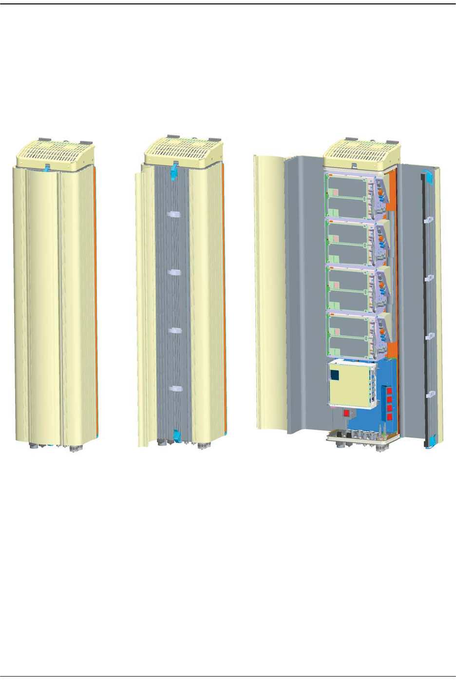
Prism Remote Units
FlexWave Prism Host, Remote and EMS 5.1 System Reference Page 45
ADCP-77-073 • Issue 2 • 11/2009 © 2009 ADC Telecommunications, Inc.
2.3.2.4 Solar Shield
The Prism solar shields are required to conduct air over the outside of the Prism. The
Prism ships with the solar shield factory installed.
Figure 2-12. Solar Shield
Quad-Band Remotes
Solar Shield is closed Solar Shield is open,
Remote door is closed
Solar Shield and Remote door are open
77073-024
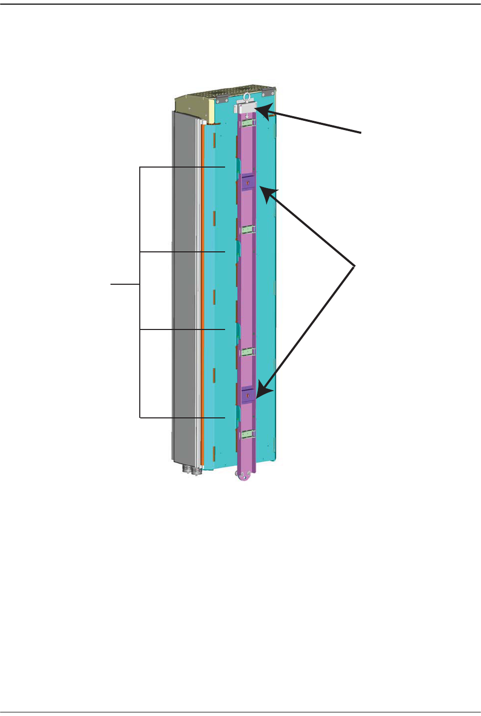
Prism System Components
Page 46 FlexWave Prism Host, Remote and EMS 5.1 System Reference
© 2009 ADC Telecommunications, Inc ADCP-77-073 • Issue 2 • 11/2009
2.3.2.5 Mounting Bracket (Remotes)
The Prism is designed to be pole or wall mounted or mounted on a flat surface.
Figure 2-13. Prism Back View—Mounting Components
Retracting-Lifting
Eye
Wall-Attachment
points (2)
Four pairs of
Mounting Hooks
77077-007
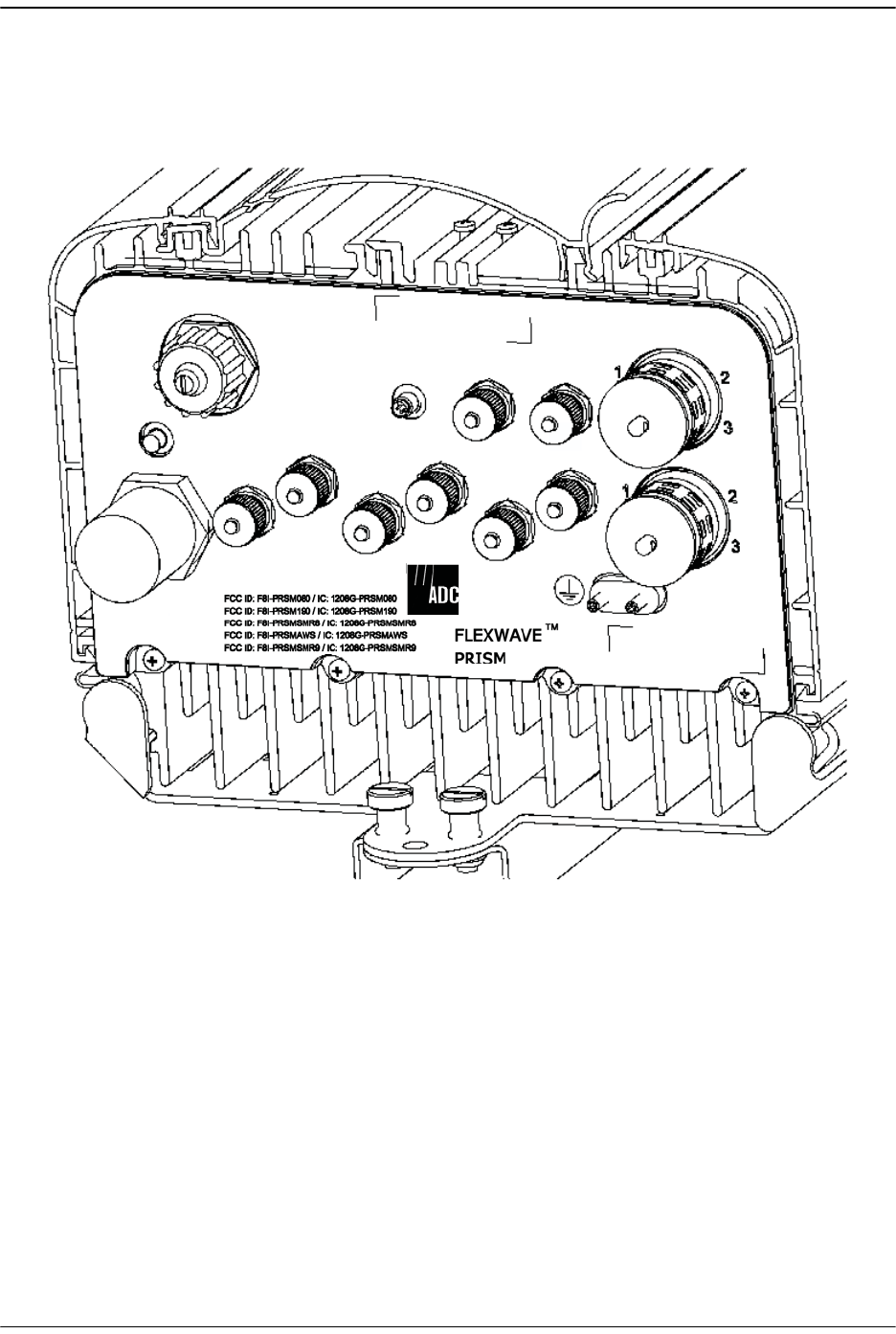
Prism Remote Units
FlexWave Prism Host, Remote and EMS 5.1 System Reference Page 47
ADCP-77-073 • Issue 2 • 11/2009 © 2009 ADC Telecommunications, Inc.
2.3.2.6 Remote Connectors
The bottom of the Remote comprises the RF, fiber and RJ-45 connectors as well as a
Status LED as indicated in Figure 2-14 and described in Table 2-3.
Figure 2-14. FlexWave Prism Remote Unit User Interface
NETWORK
AUX.
MOD A
RX1
MOD A
TX0/RX0
FIBER 1
FIBER 2
MOD B
TX0/RX0
MOD B
RX1
MOD C
TX0/RX0
MOD D
TX0/RX0
MOD C
RX1
MOD D
RX1
POWER
100-240 VAC
50-60 Hz
16 AMPS
77073-017

Prism System Components
Page 48 FlexWave Prism Host, Remote and EMS 5.1 System Reference
© 2009 ADC Telecommunications, Inc ADCP-77-073 • Issue 2 • 11/2009
Table 2-3. FlexWave Prism Remote Unit User Interface
User Interface Designation Device Functional Description
FIBER 1 BX5 Duplex Female
single-mode angled
UPC fiber (>50 dB
return loss 1)
Two fiber pairs which can support up to
140 MHz of duplexed RF spectrum.
FIBER 2 BX5 Duplex Female
single-mode angled
UPC fiber (>50 dB
return loss 1)
Two additional fiber pairs which can be
used to get to the maximum of 280 MHz of
RF spectrum.
Mod A TX0/RX0 2N-Type 50-Ohm female
RF coaxial connector
RF Module A connection point for transmit
RF power and primary receive to/from the
antenna.
Mod A RX1 N-Type 50-Ohm female
RF coaxial connector
RF Module A connection point for diversity
receive for RF power from the antenna.
Mod B TX0/RX0 N-Type 50-Ohm female
RF coaxial connector
RF Module B connection point for transmit
RF power and primary receive to/from the
antenna.
Mod B RX1 N-Type 50-Ohm female
RF coaxial connector
RF Module B connection point for diversity
receive for RF power from the antenna.
Mod C TX0/RX0 N-Type 50-Ohm female
RF coaxial connector
RF Module C connection point for transmit
RF power and primary receive to/from the
antenna.
Mod C RX1 N-Type 50-Ohm female
RF coaxial connector
RF Module C connection point for diversity
receive for RF power from the antenna.
Mod D TX0/RX0 N-Type 50-Ohm female
RF coaxial connector
RF Module D connection point for transmit
RF power and primary receive to/from the
antenna.
Mod D RX1 N-Type 50-Ohm female
RF coaxial connector
RF Module D connection point for diversity
receive for RF power from the antenna.
Network Sealed RJ-45 female
connector
Connection point for communication with
the entire connected network: Host,
Remote, and ENET connected devices at the
Remote.
Status LED Red LED At startup, the Status LED is ON (solid red)
prior to being controlled by the SeRF
processor. Otherwise, when the Remote is
in service, the Status LED is OFF.
100/240 VAC
50–60 HZ
16 Amps (Quad-Band)
13 Amps (Tri-Band)
10 Amps (Dual-Band)
6 Amps (Single-Band)
Sealed 3-wire AC
power connector
Connection point for the AC power cord.
Supplied ground lug Connection point for grounding unit.
1ADC connector specification
2Mod A/RF Module A is the bottommost Module in a Remote and Mod D/RF Module D is the
topmost module in a Quad-Band Remote.

Prism Remote Units
FlexWave Prism Host, Remote and EMS 5.1 System Reference Page 49
ADCP-77-073 • Issue 2 • 11/2009 © 2009 ADC Telecommunications, Inc.
2.3.2.7 Remote Fiber Connector Cable Assembly
A fiber connector cable assembly is provided with 10 meters of environmentally
hardened cable and 1 meter of exposed, un-terminated single-mode 900μm optical
fiber sufficient for splicing in an OSP splice tray.
2.3.2.8 Remote Antenna Cable Connections
The TX0/RX0 antenna cable connections are through 50-ohm N-type female
connectors. The Remote includes an internal Duplexer which allows a single antenna
cable to carry both forward and reverse path RF signals between the antenna and the
Remote. The RX1 diversity antenna cable connections are through 50-ohm N-type
female connectors.
2.3.2.9 Remote Grounding
A double-ground stud and ring lug is supplied with the unit. A #6 copper wire
terminated with the provided ring terminal must be provided to link the Remote to
an earth ground source.
2.3.2.10 Remote Cooling
The electronic compartment of the Prism is sealed to the environment. Prism
conducts its heat to a rear heat sink and the front doors. Two external
environmentally hardened fans are controlled and monitored by the system. When
turned on, these fans pull air over the external surfaces of the enclosure to ensure
the electronics run within their rated temperature. The fans run at three different
speeds depending on the internal temperature of the system. An alarm is generated
if a high temperature condition occurs within the enclosure.
The maximum ambient operating temp is 50°C (122°F).
The pigtail is a reduced bending radius type fiber. Therefore not all fusion splicers will
work to splice it. Do not use a splicer that uses light to align the cores.
30M, 40M, 60M, 80M, 100M and 150M fiber connector cable assemblies are also
available from ADC.
For proper and safe equipment operation, an approved earth ground connection must
be provided. The recommended minimum wire size is #6 AWG copper wire.

Prism System Components
Page 50 FlexWave Prism Host, Remote and EMS 5.1 System Reference
© 2009 ADC Telecommunications, Inc ADCP-77-073 • Issue 2 • 11/2009
2.4 PRISM SYSTEM ACCESSORIES
This section provides a brief description of various accessory items that are available
separately. The accessory items may or may not be required depending on the
application.
2.4.1 Lightning Surge Suppressor (Remote Accessory)
An externally-mounted lightning surge suppressor is available separately as an
accessory for the Remote. To reduce the chance of damage to electronic components
should a lightning strike occur, install a lightning surge suppressor at each antenna
port that connects to an outdoor antenna. The surge/antenna connector on the
lightning suppressor is an N-type female connector. The Prism Remote Unit must be
properly grounded for the lighting surge suppressor to function properly.
2.4.2 Uninterruptible Power Supply (Accessory)
Any power interruption without an external Uninterruptible Power Supply (UPS)
system will potentially result in an RF power outage. If a UPS is required it should be
designed into the site plan during the engineering process.
2.4.3 Wavelength Division Multiplexer System
(Accessory)
In some applications, it may be desirable or necessary to combine the forward path
and reverse path optical signals from a single Host/Remote pair onto a single optical
fiber. This can be accomplished by using a passive bi-directional Wavelength Division
Multiplexer (WDM) system. The optical wavelengths used in the Prism system are
1550 nm for the forward path and 1310 nm for the reverse path. Because different
wavelengths are used for the forward and reverse paths, both signals can be
combined on a single optical fiber. A WDM application is shown in Figure 2-15.
Figure 2-15. Wavelength Division Multiplexer Application
77073-053
NON-DIVERSITY FIBER OPTIC LINK
FORWARD AND
REVERSE PATH
DIVERSITY FIBER OPTIC LINK
WDM
FORWARD AND
REVERSE PATH
AND
DIVERSITY REVERSE PATH
WDM
HOST
UNIT
REMOTE
UNITS
WDM
REMOTE
UNITS
WDM
UP TO
EIGHT
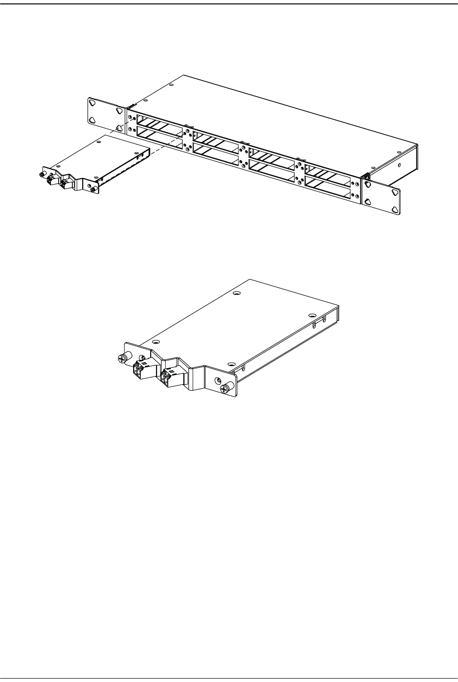
Prism System Accessories
FlexWave Prism Host, Remote and EMS 5.1 System Reference Page 51
ADCP-77-073 • Issue 2 • 11/2009 © 2009 ADC Telecommunications, Inc.
The WDM Host module mounting shelf and Host module are shown in Figure 2-16.
The WDM module is shown in Figure 2-17. WDMs at the Remote are in the fiber patch
cord and placed in the enclosure.
Figure 2-16. WDM Host Module and Host Module Mounting Shelf
Figure 2-17. Host Unit WDM Module
2.4.4 Course Wavelength Division Multiplexer System
(Accessory)
Prism Coarse Wavelength Division Multiplexer (CWDM) systems are pre-configured
with the correct wavelength SFPs installed as well as the correct wavelength OADM
module. SFPs installed in the Host provides the following optical wavelengths:
•• 1470 nm •• 1550 nm
•• 1490 nm •• 1570 nm
•• 1510 nm •• 1590 nm
•• 1530 nm •• 1610 nm
77073-054
77073-055
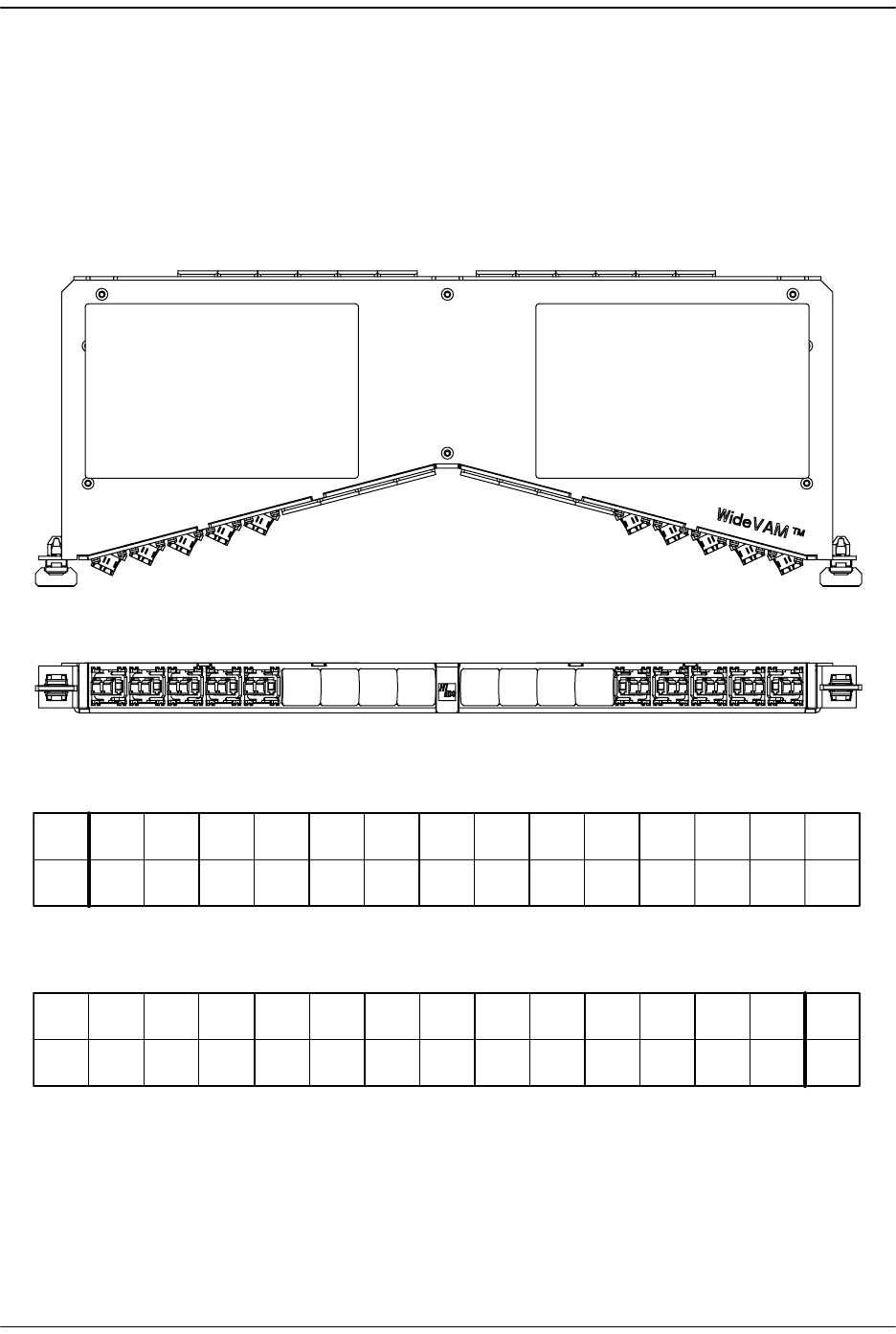
Prism System Components
Page 52 FlexWave Prism Host, Remote and EMS 5.1 System Reference
© 2009 ADC Telecommunications, Inc ADCP-77-073 • Issue 2 • 11/2009
The Host is connected to a CWDM chassis that contains the CWDM Mux/DeMux Units
that multiplex the wavelengths from the transceivers onto a single fiber in the
Forward path and de-multiplexes the wavelengths from the Remotes into their
respective wavelengths. The Remote within a CWDM system requires an internal
Prism CWDM Fiber Cable Assembly. Figure 2-18 on Page 52 shows the CWDM
Mux/DeMux unit and Figure 2-19 shows the CWDM Fiber Cable Assembly. For further
information on the Prism CWDM system, see the ADC FlexWave™ Prism Coarse
Wavelength Division Multiplexer User Manual (ADCP-75-353).
Figure 2-18. Prism Multiplexer/DeMultiplexer
LEFT SIDE PORTS (DEMUX) RIGHT SIDE PORTS (MUX)
19 20 21 22 23 24 25 26 27 28 29 30 31 32 33 34 35 361 2 3 4 5 6 7 8 9 10 11 12 13 14 15 16 17 18
NOT
USED
NOT
USED
NOT
USED
NOT
USED
NOT
USED
CWDM
PORTS
CWDM
PORTS
1 2 3 4 5 6 7 8 9 10 11 12 13 14 15 16 17 18
NOT
USED
NOT
USED
NOT
USED
NOT
USED
NOT
USED
19 20 21 22 23 24 25 26
COM
36353433323130292827
COM
1611 1591 1571 1551 1531 1511 1491 1471
16111591157115511531151114911471
DEMUX PORTS (FRONT, LEFT SIDE OF CWDM MUX/DEMUX UNIT)
MUX PORTS (FRONT, RIGHT SIDE OF CWDM MUX/DEMUX UNIT)
77073-056
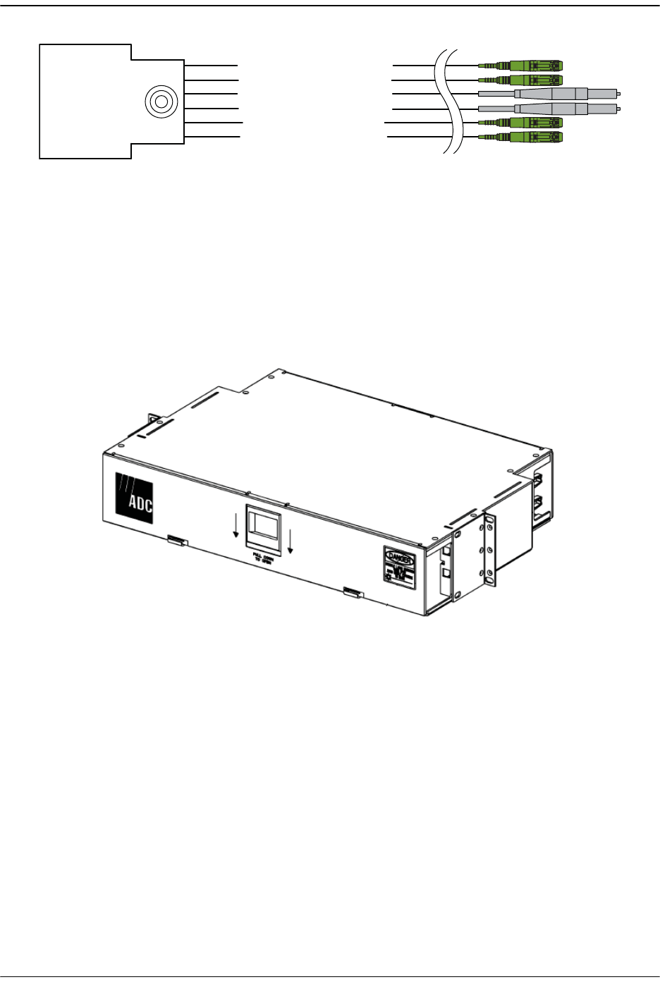
Prism System Accessories
FlexWave Prism Host, Remote and EMS 5.1 System Reference Page 53
ADCP-77-073 • Issue 2 • 11/2009 © 2009 ADC Telecommunications, Inc.
Figure 2-19. CWDM Fiber Cable Assembly
The Prism CWDM system works with ADC’s 7- and 3.5-inch industry-standard
WideVAM chassis to ensure consistent, superior cable management within the frame.
The 3.5-inch standard VAM chassis fits into any 19-inch rack mounting environment.
It accommodates a maximum of 4 plug-in modules, 4 bulkhead plates, 4 blank panels
or any combination thereof. Adjustable mounting brackets are provided for 23-inch
rack mounting environments.
Figure 2-20. 3.5-Inch Standard VAM Chassis (FVM-19x350-M6)
OUT FROM OADM 1, REV SEC
FWD (DROP FROM OADM 1 & 2)
REV (ADD FROM OADM 1 & 2)
IN FROM OADM 2, FWD SEC
IN FROM OADM 1, FWD PRIM
OUT FROM OADM 2, REV PRIM
77073-057
77073-051
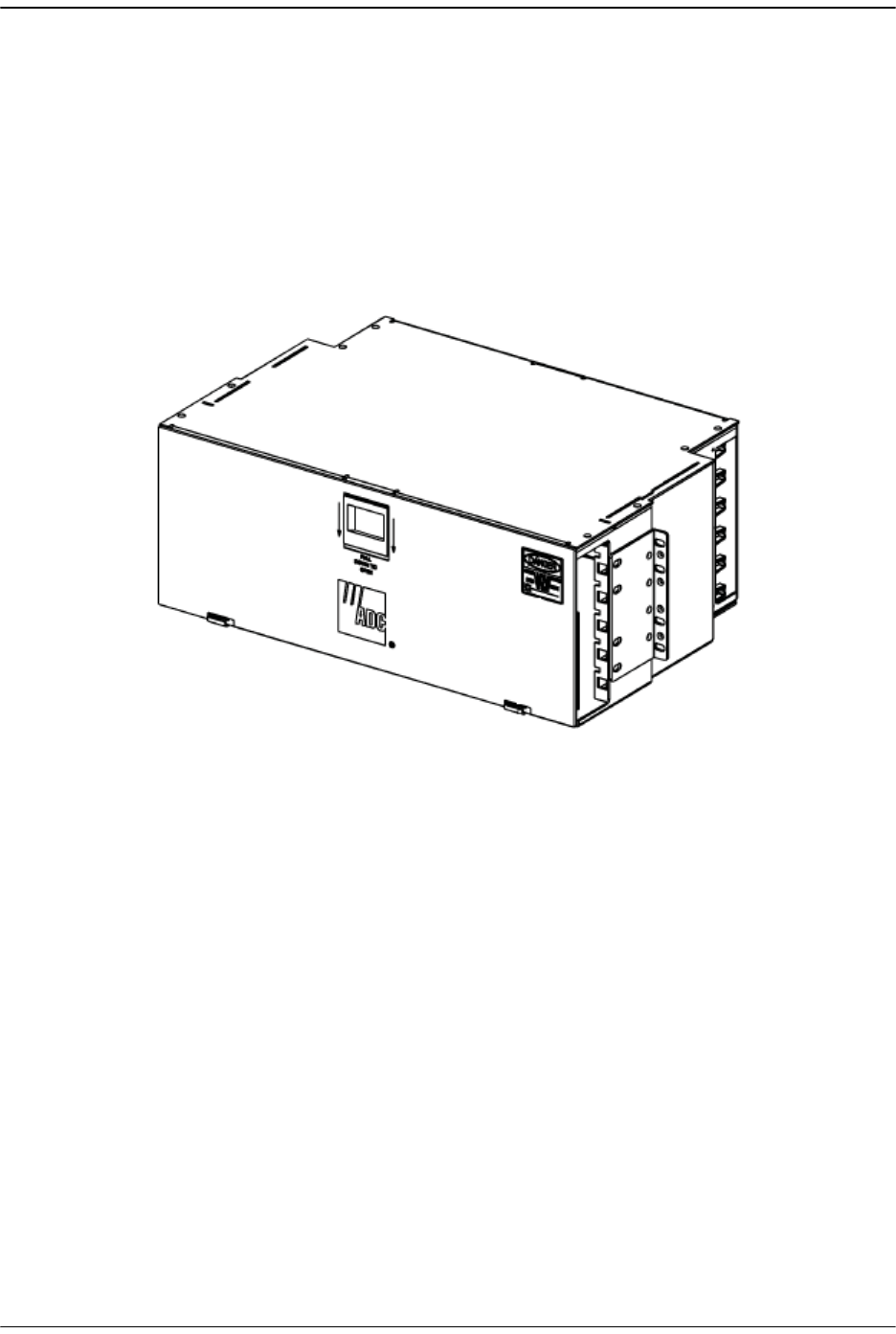
Prism System Components
Page 54 FlexWave Prism Host, Remote and EMS 5.1 System Reference
© 2009 ADC Telecommunications, Inc ADCP-77-073 • Issue 2 • 11/2009
The 7-inch standard VAM chassis fits into any open chassis location within an
existing ADC 7-inch panel system or in an LGX® compatible frame. It accommodates
a maximum of six components, in any combination of the following:
•• single plug-in modules
•• bulkhead plates
•• blank panels.
The 7-inch chassis mounts in EIA or WECO racks. Adjustable mounting brackets are
provided for 19- or 23-inch rack mounting environments.
Figure 2-21. 7-inch Standard VAM Chassis (FVM-19X700W)
77073-052

Prism System Accessories
FlexWave Prism Host, Remote and EMS 5.1 System Reference Page 55
ADCP-77-073 • Issue 2 • 11/2009 © 2009 ADC Telecommunications, Inc.
2.4.5 Millimeter Wave Systems (Accessory)
A Millimeter Wave (MMW) system with a data rate of not less than 3 Gbps (that meets
the FlexWave Prism data rate performance and BER requirements) may be used in
applications where it is desirable or necessary to bridge an open span and where it is
impractical to lay a fiber optic cable. One MMW transceiver unit may be mounted on
the Host side of the open span and the other MMW transceiver unit may be mounted
on the Remote side of the open span. A system diagram of an MMW application is
shown in Figure 2-22. MMW systems are available from various equipment
manufacturers.
Figure 2-22. FlexWave Millimeter Wave Application
A mmw link (3GBps) is required for 12 timeslots worth of RF traffic between the Host
and the Remote. This is roughly 60 - 75MHz depending on the modulation. If a
Remote has more bandwidth requirements (such as 210MHz of RF), there would need
to be 3 point-to-point mmw links.
77073-058
UP TO EIGHT
REMOTE
UNITS
FORWARD PATH
MMW
TX/RX
MMW
TX/RX
FLEXWAVE MILLIMETER WAVE
REVERSE PATH
FORWARD PATH
REVERSE PATH
HOST
UNIT

Prism System Components
Page 56 FlexWave Prism Host, Remote and EMS 5.1 System Reference
© 2009 ADC Telecommunications, Inc ADCP-77-073 • Issue 2 • 11/2009
2.5 PRISM SYSTEM SPECIFICATIONS
2.5.1 Host Unit Specifications
Parameter Specification Remarks
Dimensions (HuWuD) 5.17 u17.26u9.5 inches
(131.3 u 438.4 u 241.3 mm)
Dimension for width does not
include the mounting brackets
which can be installed for either
19- or 23-inch racks.
Mounting 19- or 23-inch rack EIA or WECO
Weight 20 lbs. (9.1 kg)
Weather resistance Indoor installation only Environmentally controlled
outdoor
cabinet.
Operating temperature 0º to 55º C (32º to 131º F)
Storage temperature –40º to 70º C (–40º to 158ºF)
Humidity 10% to 90% No condensation
Optical ports SFP transceivers LC (UPC)
Optical power levels Launch power
Minimum: -2 dBm
Maximum: 3 dBm
Receive power
Minimum: -27 dBm
Maximum: -9 dBm
Transceivers Wavelengths:
• Host transmits a 1550 nm
signal
• Remote transmits a 1310 nm
signal
• Host and Remote can receive
either a 1550 or 1310 nm
signal
For information on transceiver
transmissions with a CWDM, see
the ADC FlexWave Prism Coarse
Wavelength Division Multiplexer
User Manual (ADCP-75-353).
External alarm connector Screw-type terminals NO, COM, and NC relay contacts
DC Power ±20 – ±60 Vdc
Power consumption Maximum: 320 Watts
Nominal: 202 Watts
Current rating 4.2 Amps
8.4 Amps
At –48Vdc
At +24Vdc
RF coaxial cable connectors 50 ohm QMA – type (female) 50 ohms input/output
impedance
Network and Craft connectors RJ–45 jack
Reliability at 25ºC MTBF 200,000 hours Including fans

Prism System Specifications
FlexWave Prism Host, Remote and EMS 5.1 System Reference Page 57
ADCP-77-073 • Issue 2 • 11/2009 © 2009 ADC Telecommunications, Inc.
2.5.2 Remote Unit Specifications
Parameter Specification Remarks
Enclosure dimensions (HuWuD)
Single-Band 23.1" x 12.15" x 10.125"
(58.67 cm x 30.86 cm x 25.71
cm)
Dual-Band 31.1" x 12.15" x 10.125"
(78.99 cm x 30.86 cm x 25.71
cm)
Tri-Band 39.1" x 12.15" x 10.125"
(99.31 cm x 30.86 cm x 25.71
cm)
Quad-Band 50.2" x 12.15" x 10.125"
(127.51 cm x 30.86 cm x 25.71
cm)
Mounting Wall, Pole, Inside Pole, and
Vault
Weight (with solar shields installed)
Single-Band 64 lbs. (29 kg)
Dual-Band 96 lbs. (43 kg)
Tri-Band 127 lbs. (58 kg)
Quad-Band 163 lbs. (74 kg)
Outside Ambient
Temperature Rating -40° C to +50° C (-40º F to
+122º F)
Storage Temperature -40° C to +70° C (-40º F to
+158º F)
Humidity 10% to 90% non-condensing
Lightning Protection 20kA IEC 1000-45 8/30 ìs
Waveform
Provided by external lightning
protector (accessory)
Weather Resistance IP-65 Indoor or outdoor installation
Cooling Fan, IP-55
Connectors
Network port RJ-45 female connector
AC power connector Sealed 3-pin Connection point for the AC power
cord
Antenna cable connector 50 ohm N-Type (female) 50 ohms input/output impedance
Voltage input 100 to 240 VAC, 50 to 60 Hz Operating range 90 to 265 VAC
Current rating 15 AMPS

Prism System Components
Page 58 FlexWave Prism Host, Remote and EMS 5.1 System Reference
© 2009 ADC Telecommunications, Inc ADCP-77-073 • Issue 2 • 11/2009
2.5.3 System Nominal Optical Specifications
Parameter Specification aRemarks
Optical - Host and Remote
Unit
Fiber type
9/125, single-mode
Number of fibers required
Non-diversity with WDM
Diversity with WDM
Non-diversity without
WDM
Diversity without WDM
1
1
2
2
Assumes RF bandwidth does
not exceed 3 Gbps data rate
capacity of the fiber.
Forward path wavelength 1550 nm
Reverse path wavelength 1310 nm
Diversity path wavelength 1310 nm
Optical power levels Launch power
Minimum: -2 dBm
Maximum: 3 dBm
Receive power
Minimum: -27 dBm
Maximum: -9 dBm
Optical budget 25 dB For optical BER of 10–6
Optical connectors Industry standard LC Host and WDM
Optical - Host and Remote
WDM
WDM Passband 1310 nm ± 20 nm
1550 nm ± 20 nm
Forward path insertion loss
Host WDM
Remote WDM
0.7 dB
0.3 dB
Does not include connector
loss
Reverse path insertion loss
Host WDM
Remote WDM
0.3 dB
0.7 dB
Does not include connector
loss
Isolation > 30 dB minimum
Return loss (Reflectance) < –50 dB All input ports
aAll specifications apply after a five minute warm-up period.

Prism System Specifications
FlexWave Prism Host, Remote and EMS 5.1 System Reference Page 59
ADCP-77-073 • Issue 2 • 11/2009 © 2009 ADC Telecommunications, Inc.
Intentionally Blank Page

Prism System Components
Page 60 FlexWave Prism Host, Remote and EMS 5.1 System Reference
© 2009 ADC Telecommunications, Inc ADCP-77-073 • Issue 2 • 11/2009

FlexWave Prism Host, Remote and EMS 5.1 System Reference Page 61
ADCP-77-073 • Issue 2 • 11/2009 © 2009 ADC Telecommunications, Inc.
PART II
HOST AND REMOTE INSTALLATION

Page 62 FlexWave Prism Host, Remote and EMS 5.1 System Reference
© 2009 ADC Telecommunications, Inc ADCP-77-073 • Issue 2 • 11/2009
Intentionally Blank Page

FlexWave Prism Host, Remote and EMS 5.1 System Reference Page 63
ADCP-77-073 • Issue 2 • 11/2009 ©2009 ADC Telecommunications, Inc.
3INSTALLING THE HOST UNIT
3.1 Before Starting Installation................................................................................. 64
3.2 Tools and Materials............................................................................................ 65
3.3 Install the Host ................................................................................................. 66
3.3.1 Unpacking and Inspection........................................................................... 66
3.3.2 Install Host in Equipment Rack .................................................................... 66
3.3.3 OSP Fiber Cable Installation Guidelines......................................................... 68
3.3.4 Chassis Ground Connection......................................................................... 69
3.3.5 Coaxial Cable Connections .......................................................................... 70
3.3.6 Optical Connections ................................................................................... 72
3.3.7 LC Attenuator ........................................................................................... 73
3.3.7.1 Optical Connections Without WDM System ............................................ 74
3.3.7.2 Optical Connections For Systems With a WDM ....................................... 76
3.3.8 EXT REF Connections ................................................................................. 78
3.3.9 Computer Connection (Craft) ...................................................................... 80
3.3.10 System Alarm Connections........................................................................ 81
3.3.11 Power Connections................................................................................... 83
3.4 Installing the WDM Host Module Mounting Shelf and WDM Host Module .................... 87
3.4.1 Wavelength Division Multiplexer System Overview ......................................... 87
3.4.2 Install WDM Host Components .................................................................... 90
This section provides the installation procedures for the Host and the WDM Host
module (accessory item). Installation of the Remote components may proceed
separately from installation of the Host.
Content Page

Installing the Host Unit
Page 64 FlexWave Prism Host, Remote and EMS 5.1 System Reference
© 2009 ADC Telecommunications, Inc ADCP-77-073 • Issue 2 • 11/2009
3.1 BEFORE STARTING INSTALLATION
Do the following before you begin installation.
•• Review the system design plan.
•• Identify the equipment installation site.
•• Make sure all cable runs are mapped out.
•• Identify and obtain all tools and materials required to complete the installation.

Tools and Materials
FlexWave Prism Host, Remote and EMS 5.1 System Reference Page 65
ADCP-77-073 • Issue 2 • 11/2009 © 2009 ADC Telecommunications, Inc.
3.2 TOOLS AND MATERIALS
The following tools are required to complete the procedures in this section:
•• Medium size flat-bladed screwdriver
•• Phillips screwdriver (#2)
•• Pliers
•• Wire cutters
•• Wire stripper
•• Tool kit for attaching QMA-Type male connectors to coaxial cable
•• Crimp tool to attach ring terminals
•• Multimeter
•• Optical power meter
•• Fiber cleaning equipment
The following materials are required to complete the procedures in this section:
•• #18 AWG (1.0 mm) insulated stranded copper wire (for chassis grounding wire)
•• #18 AWG (1.0 mm) red and black insulated copper wire (for DC power wires)
•• Category 3 or 5 cable (for external alarm system wires)
•• Category 5 cable with RJ45 connectors for the Network and Craft port
•• #6 ring terminal (1) for #18 wire (for chassis ground wire connection)
•• #6 fork terminals (2) for #18 wire (for DC power wiring connection)
•• Single-mode patch cord(s) with LC connectors (1 – 8 depending on the application)
•• High performance, flexible, low-loss 50-ohm coaxial cable
•• QMA-type male connectors
•• Wire ties

Installing the Host Unit
Page 66 FlexWave Prism Host, Remote and EMS 5.1 System Reference
© 2009 ADC Telecommunications, Inc ADCP-77-073 • Issue 2 • 11/2009
3.3 INSTALL THE HOST
This chapter guides you through installing a Prism Host, which requires 70 steps that
are divided into 11 sections. Follow the steps in the order in which they are provided.
3.3.1 Unpacking and Inspection
This section provides instructions for opening the shipping boxes, verifying that all
parts have been received, and verifying that no shipping damage has occurred.
11 Inspect the exterior of the shipping container(s) for evidence of rough handling
that may have damaged the components in the container.
22 Unpack each container while carefully checking the contents for damage and
verify with the packing slip.
33 If damage is found or parts are missing, file a claim with the commercial carrier
and notify ADC Customer Service (see “Contacting ADC” on page 335). Save the
damaged cartons for inspection by the carrier.
44 Save all shipping containers for use if the equipment requires shipment at a
future date.
3.3.2 Install Host in Equipment Rack
A pair of reversible mounting brackets is provided that allow the Host to be mounted
in either a 19-inch or 23-inch EIA or WECO equipment rack. When installed, the Host
front panel is flush with the front of the rack.
Both US standard and metric machine screws are included for rack mounting the
Host. When loading the Host in a rack, make sure the mechanical loading of the rack
is even to avoid a hazardous condition such as an unbalanced rack. The rack should
safely support the combined weight of all the equipment it holds.
The maximum ambient temperature for the Host is 55º C (131º F).
The Host to be mounted in either a 19- inch or 23- inch EIA or WECO equipment rack.
Unless noted otherwise, views of the Host show the mounting brackets in the 23- inch
position.
Wet conditions increase the potential for receiving an electrical shock when installing or
using electrically powered equipment. To prevent electrical shock, never install or use
electrical equipment in a wet location or during a lightning storm.
To insure that all optical connectors remain dust- free during installation, leave all dust
caps and dust protectors in place until directed to remove them for connection.
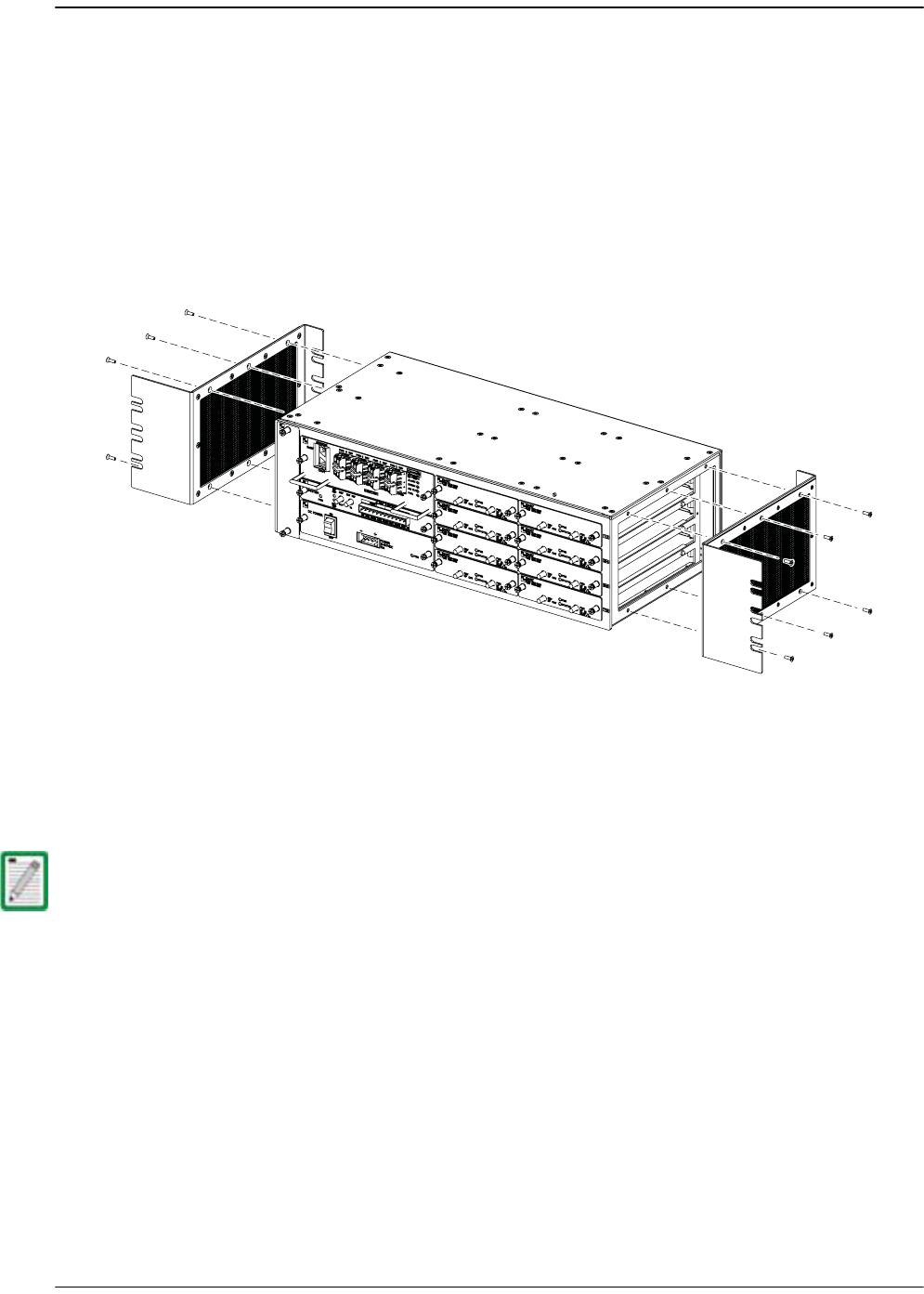
Install the Host
FlexWave Prism Host, Remote and EMS 5.1 System Reference Page 67
ADCP-77-073 • Issue 2 • 11/2009 © 2009 ADC Telecommunications, Inc.
Use the following procedure to install the Host in the equipment rack:
55 The Host is shipped with the mounting brackets installed for 19-inch rack
installations. If mounting the Host in a 19-inch rack, proceed to Step 6. If
mounting the Host in a 23-inch rack, proceed to Step 8.
66 Remove both mounting brackets from the Host (requires TORX screwdriver with
T20 bit) and save screws (six-screws on each side) for reuse.
77 Reinstall both mounting brackets so the long side of the bracket is flush with the
Host front panel as shown below. Use the screws removed in Step 6 to re-attach
the brackets to the Host chassis.
88 Position the Host in the designated mounting space in the rack (per system design
plan) and then secure (but do not tighten) the Host to the rack using the four
machine screws provided (use #12-24 or M6 x 10 screws, whichever is
appropriate).
99 Locate two vertical cable guides, not provided with the Host.
100 Back out the Host mounting screws just enough to provide clearance for
installation of the cable guides.
111 Slide each cable guide into position for installation and then securely tighten the
corresponding mounting screws.
A vertical cable guide kit is available separately as an accessory.
Install Mounting
Brackets as shown for
installation in 23-inch Racks
77073-060
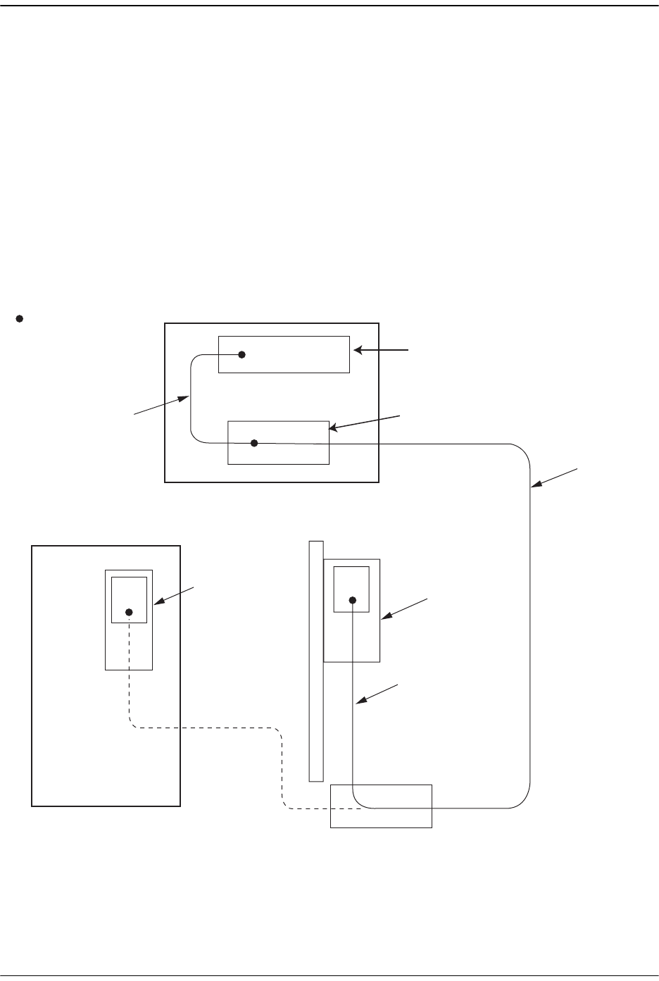
Installing the Host Unit
Page 68 FlexWave Prism Host, Remote and EMS 5.1 System Reference
© 2009 ADC Telecommunications, Inc ADCP-77-073 • Issue 2 • 11/2009
3.3.3 OSP Fiber Cable Installation Guidelines
The outside plant (OSP) fiber optic cables should be routed between the Host
distribution panel and Remote outside plant cabinet and terminated before the
equipment is installed. A diagram of a typical OSP cable routing is shown in
Figure 3-1. At the Host, the OSP cable should be terminated at a fiber distribution
panel and spliced to fiber patch cords. Jumper patch cords may then be used to link
the Host optical ports to the OSP cable terminations. Whenever possible, a guideway
such as the FiberGuide system should be provided to protect the fiber optic patch
cords from damage and to prevent excessive bending. The procedures for connecting
the OSP cable optical fibers to the Host is provided in “Optical Connections Without
WDM System” on page 74. and “Optical Connections For Systems With a WDM” on
page 76.
Figure 3-1. Typical Fiber Optic Cable Routing
Host Unit
Fiber
Distribution
Panel
Outdoor
Remote Site
Host Site
Patch
cords
Indoor/Outdoor
Quad Cable with
Pre-Terminated
Connector *
Outside Plant
Cable
Remote
Unit
77073-059
Indoor
Remote Site
X
Splice
Termination
X
Remote
Unit
Outside Plant
Cabinet
X
* One end of the Quad cable is
connectorized, and the other end
is stub
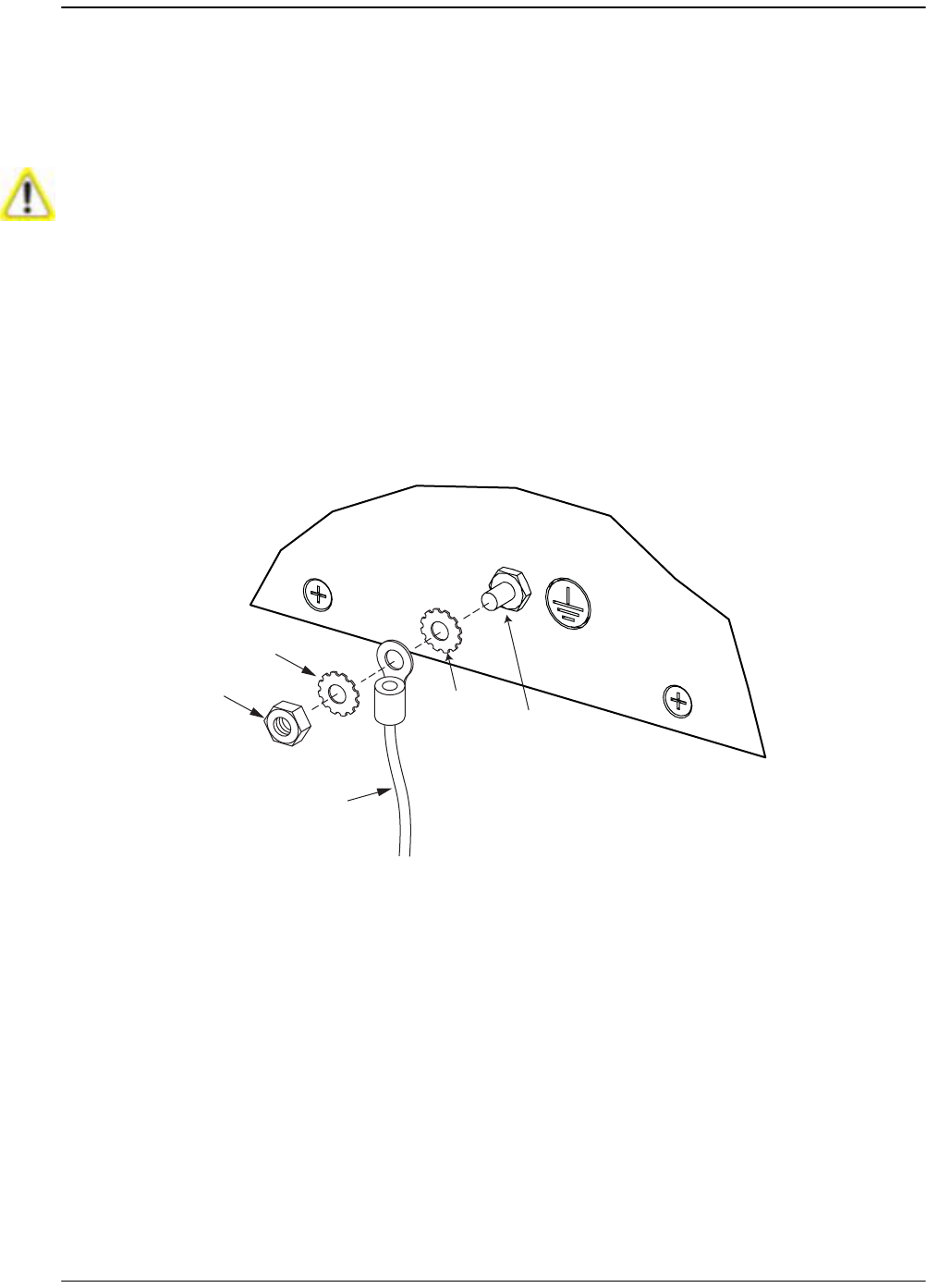
Install the Host
FlexWave Prism Host, Remote and EMS 5.1 System Reference Page 69
ADCP-77-073 • Issue 2 • 11/2009 © 2009 ADC Telecommunications, Inc.
3.3.4 Chassis Ground Connection
A stud is provided on the rear side of the chassis for connecting a grounding wire to
the chassis. Use the following procedure to connect the grounding wire to the chassis
and to route the grounding wire to an approved earth ground source.
122 Obtain a length of #18 AWG (1.00 mm) insulated stranded copper wire for use as
a chassis grounding wire.
133 Terminate one end of the wire with a ring terminal.
144 Locate the chassis-ground stud at the rear of the Host chassis as shown in in the
following graphic, and then attach the ring end of the wire to the chassis ground
stud.
155 Route the free end of the chassis grounding wire to an approved (per local code
or practice) earth ground source.
166 Cut the chassis grounding wire to length and connect it to the approved ground
source as required by local code or practice.
Maintain reliable grounding. Pay particular attention to ground source connections.
Rear of Host Chassis
Star
washer
Hex
nut
Ground
wire
77073-062
Star
washer Chassis-
ground
stud

Installing the Host Unit
Page 70 FlexWave Prism Host, Remote and EMS 5.1 System Reference
© 2009 ADC Telecommunications, Inc ADCP-77-073 • Issue 2 • 11/2009
3.3.5 Coaxial Cable Connections
The RF interface between the Host DART card and the EBTS/BTS is supported through
two type QMA female connectors mounted on each DART front panel. One connector
provides the coaxial cable connection for the forward path (downlink) signal and the
other connector provides the coaxial cable connection for the reverse path (uplink)
signal.
In most installations, it is usually necessary to insert an external attenuator into the
forward path link between the Host and the BTS. Before completing the forward path
connection at the BTS, verify that the composite forward path RF signal level at the
Host is between –25 and +5 dBm.
The Host should be mounted as close as possible to the EBTS/BTS to minimize cable
losses. Use the following procedure to route and connect the forward and reverse
path coaxial cables to the Host DART cards:
177 Obtain the required lengths of high performance, flexible, low loss 50-ohm coaxial
communications cable (RG-400 or equivalent) for all coaxial connections.
188 Route the forward and reverse path coaxial cables between the Host and the BTS
interface (per system design plan) and cut to the required length. Allow sufficient
slack for dressing and organizing cables at the Host and for installing an external
attenuator in the forward path link.
199 Terminate each cable with a QMA-Type male connector following the connector
supplier’s recommendations.
200 If required, install an external attenuator in the forward path.
211 Connect the forward and reverse path cables as shown in the following graphic.
aa Connect the forward path cable to the FWD RF IN connector on the Host DART
front panel.
bb Connect the reverse path cable to the REV RF OUT connector on the Host DART
front panel.
The composite forward path RF signal level at the Host must be between –25 and + 5
dBm. Do not connect the forward path cable until the composite forward path RF signal
level is measured and the amount of external attenuation required is determined.
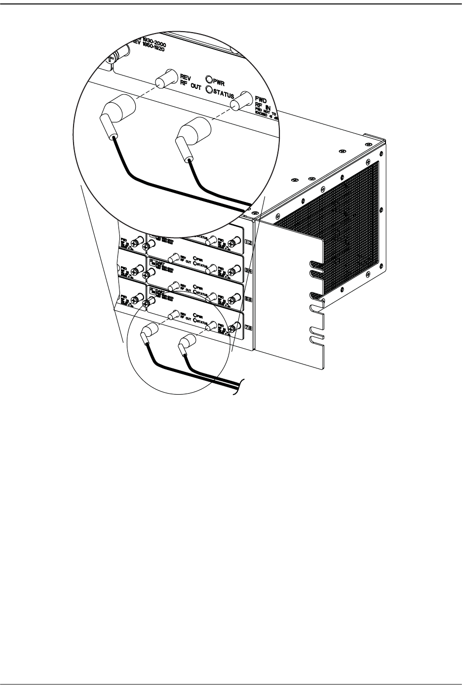
Install the Host
FlexWave Prism Host, Remote and EMS 5.1 System Reference Page 71
ADCP-77-073 • Issue 2 • 11/2009 © 2009 ADC Telecommunications, Inc.
222 Repeat this procedure for the remaining DART cards in the Host.
233 Dress and secure cables at the right side of the Host.
244 Complete all remaining coaxial connections as specified in the system design
plan.
77073-063

Installing the Host Unit
Page 72 FlexWave Prism Host, Remote and EMS 5.1 System Reference
© 2009 ADC Telecommunications, Inc ADCP-77-073 • Issue 2 • 11/2009
3.3.6 Optical Connections
Optical connections between the Host SeRF card and the Remote are supported
through Small Form-Factor Pluggable (SFP) transceivers. The optical interfaces are
standard single-mode duplex LC (flat polished UPC). One SFP comes with the
Host—additional SFPs (up to 7) must be ordered separately as needed.
There are two fiber connections—one FWD and one REV—for each SFP. As the SeRF
holds up to eight SFPs, there is a total of 16 connections: eight FWD and eight REV.
The FWD path is 1550nm (from the Host to the Remote) and the REV path is 1310nm
(from the Remote to the Host).
Each FWD port provides an optical connection for the forward path (downlink) signal.
Each REV port provide an optical connection for the reverse path (uplink) signal. Each
REV port can also provide the optical connection for the diversity reverse path
(uplink) signal.
The optical connections are dependent on whether or not a WDM Host module
(accessory) is installed:
•• If the installation does not include a WDM module, proceed to Section 2.9.2 for
the optical connections procedure.
•• If the installation includes a WDM module, proceed to Section 2.10 for the optical
connections procedure.
This equipment uses a Class 1 Laser according to FDA/CDRH rules. Laser radiation can
seriously damage the retina of the eye. Do not look into the ends of any optical fiber. Do
not look directly into the optical transmitter of any unit or exposure to laser radiation
may result. An optical power meter should be used to verify active fibers. A protective
cap or hood MUST be immediately placed over any radiating transmitter or optical fiber
connector to avoid the potential of dangerous amounts of radiation exposure. This
practice also prevents dirt particles from entering the connector.
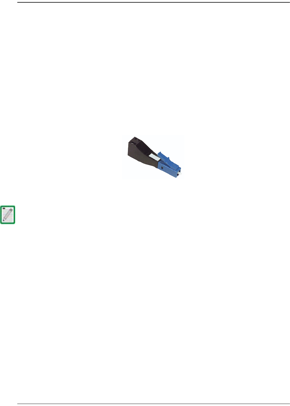
Install the Host
FlexWave Prism Host, Remote and EMS 5.1 System Reference Page 73
ADCP-77-073 • Issue 2 • 11/2009 © 2009 ADC Telecommunications, Inc.
3.3.7 LC Attenuator
To meet 3Gbps optical transmission requirements, the long reach transceivers (SFPs)
must be used. SFPs have the following specifications:
•• Launch: 0dBm
•• Normal Operation: -9dBm maximum to -27dBm minimum
•• Overdrive: >-9dBm
•• Underdrive: <-27dBm
•• RX No Light condition: <-34dBm
The receiver’s specification is -9 to -27dBm. Based on typical fiber runs, there's
usually only a few dB of loss, so the 15dB LC attenuator (Figure 3-2) ships with each
Host to put the receive level in the optimum receive range.
Figure 3-2. LC Attenuator
There is an option of ordering the WDM with a fiber pigtail. The document for the WDM
option describes using the LC attenuator option and requires an additional fiber patch
cord.
77073-064

Installing the Host Unit
Page 74 FlexWave Prism Host, Remote and EMS 5.1 System Reference
© 2009 ADC Telecommunications, Inc ADCP-77-073 • Issue 2 • 11/2009
3.3.7.1 Optical Connections Without WDM System
Use the following procedure to connect the optical fibers when a WDM is not
installed.
255 Obtain two patch cords that are of sufficient length to reach from the Host to the
fiber distribution panel.
266 Designate one of the patch cords as the forward path link and the other as the
reverse path link and attach an identification label or tag next to the connector.
277 Remove the dust caps from the Host SeRF SFP optical ports and from the patch
cord connectors that will be connected to the SeRF SFP optical ports.
288 Clean each patch cord connector following the patch cord supplier’s
recommendations.
299 Connect the LC attenuator to the patch cord.
300 Plug the FWD and REV path patch cords to the corresponding transmit (FWD) and
receive (REV) connections depending on the remote node SFP position.
Improper handling can damage fiber optic cables. Do not bend fiber optic cable more
sharply than the minimum recommended bend radius specified by the cable
manufacturer. Do not apply more pulling force to the cable than specified.
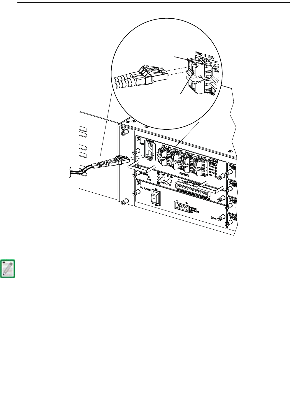
Install the Host
FlexWave Prism Host, Remote and EMS 5.1 System Reference Page 75
ADCP-77-073 • Issue 2 • 11/2009 © 2009 ADC Telecommunications, Inc.
311 Route the patch cords from the Host to the fiber distribution panel.
322 At the fiber distribution panel, identify the OSP cable optical fiber terminations
that correspond to the forward and reverse paths.
333 Remove the dust caps from the OSP cable optical fiber adapters and from the
patch cord connectors.
344 Clean each patch cord connector (follow patch cord supplier’s recommendations)
and then mate the connector with the appropriate OSP cable adapter.
355 Repeat this procedure for the remaining SeRF SFPs in the Host.
366 Store any excess patch cord slack at the fiber distribution panel or storage panel.
The Host optical adapters are angled to the left. Therefore, always route patch cords to
the Host from the left side of the rack. Routing patch cords to the Host from the right
may exceed the bend radius limitations for the optical fiber.
77073-033
FWD path
REV path
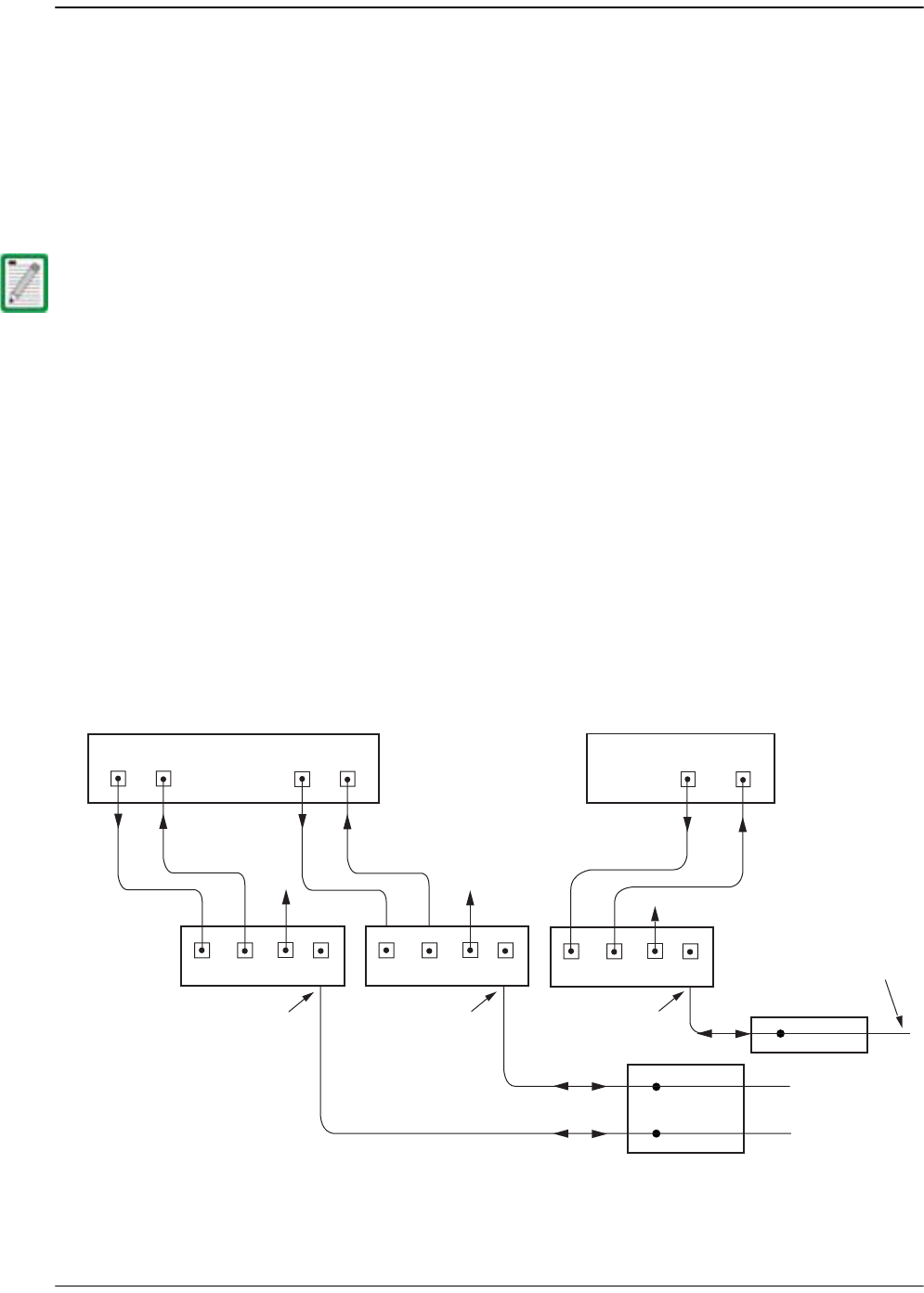
Installing the Host Unit
Page 76 FlexWave Prism Host, Remote and EMS 5.1 System Reference
© 2009 ADC Telecommunications, Inc ADCP-77-073 • Issue 2 • 11/2009
3.3.7.2 Optical Connections For Systems With a WDM
Use the following procedure to connect the optical fibers when a WDM module is
installed with the Host.
377 Obtain a patch cord that is of sufficient length to reach from the WDM module to
the fiber distribution panel.
388 Remove the dust cap from the WDM port on the WDM module and from the patch
cord connector that will be connected to the WDM module.
399 Clean the patch cord connector (follow patch cord supplier’s recommendations).
400 Insert the connector into the WDM port on the WDM module.
411 Obtain two patch cords that are of sufficient length to reach from the WDM
module to the Host.
422 Designate one of the patch cords as the forward path link and the other as the
reverse path link and attach an identification label or tag next to the connector.
433 Remove the dust caps from the Host SeRF SFP optical ports and from the patch
cord connectors that will be connected to the SeRF SFP optical ports.
444 Connect the LC attenuator (see Figure 3-2 on Page 73) to the patch cord.
455 Refer to the following diagram to understand the fiber optic connections to the
WDM module.
WDM module ports are labeled FWD, REV, TEST, and WDM.
Fiber Distribution
Panel (FDP)
X
X
Host Unit 1
PORT 8
FWD
PORT 8
REV
REV
path
FWD
path
Wavelength
Division
Multiplexers 1234
PORT 1
FWD
PORT 1
REV
Host Unit 2
REV
path
FWD
path
77073-065
To/From
Remote Unit 1
To/From
Remote Unit 1
Host Unit 1
(Bi-Directional Fiber
Link With Remote Unit)
Host Unit 1
(Bi-Directional Fiber
Link With Remote Unit)
PORT 1
FWD
PORT 1
REV
REV
path
FWD
path
1234
TestTest
1234
Test
Fiber Distribution
Panel (FDP)
X
To/From
Remote Unit 2
Host Unit 2
(Bi-Directional Fiber
Link With Remote Unit)
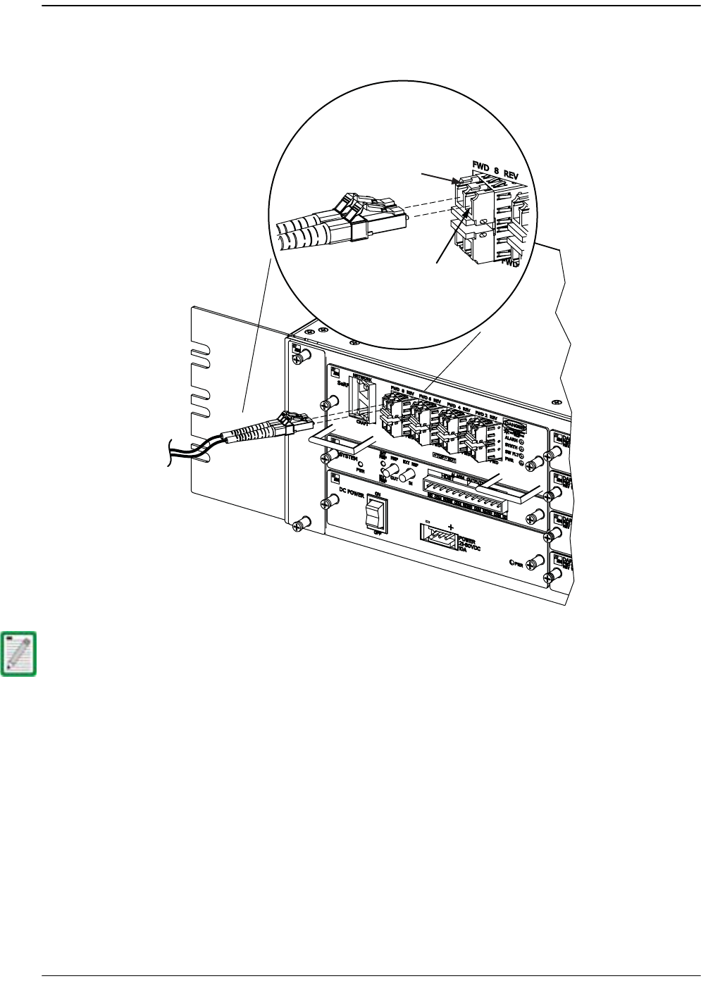
Install the Host
FlexWave Prism Host, Remote and EMS 5.1 System Reference Page 77
ADCP-77-073 • Issue 2 • 11/2009 © 2009 ADC Telecommunications, Inc.
466 Clean each fiber patch cord connector and then insert the connector into the
appropriate optical port on the Host as shown below.
477 (Optional) If adding CWDM accessories, see the ADC FlexWave™ Prism Coarse
Wavelength Division Multiplexer User Manual (ADCP-75-353) for installation
information. (For an overview of a Prism CWDM system, see Section 1.2, Course
Wavelength Division Multiplexer System, on page 4).
The Host SeRF SFP optical adapters are angled to the left. Therefore, fiber patch cords
should always be routed to the Host from the left side of the rack. Routing fiber patch
cords to the Host from the right side of the rack may exceed the bend radius limitations
for the optical fiber.
77073-033
FWD path
REV path
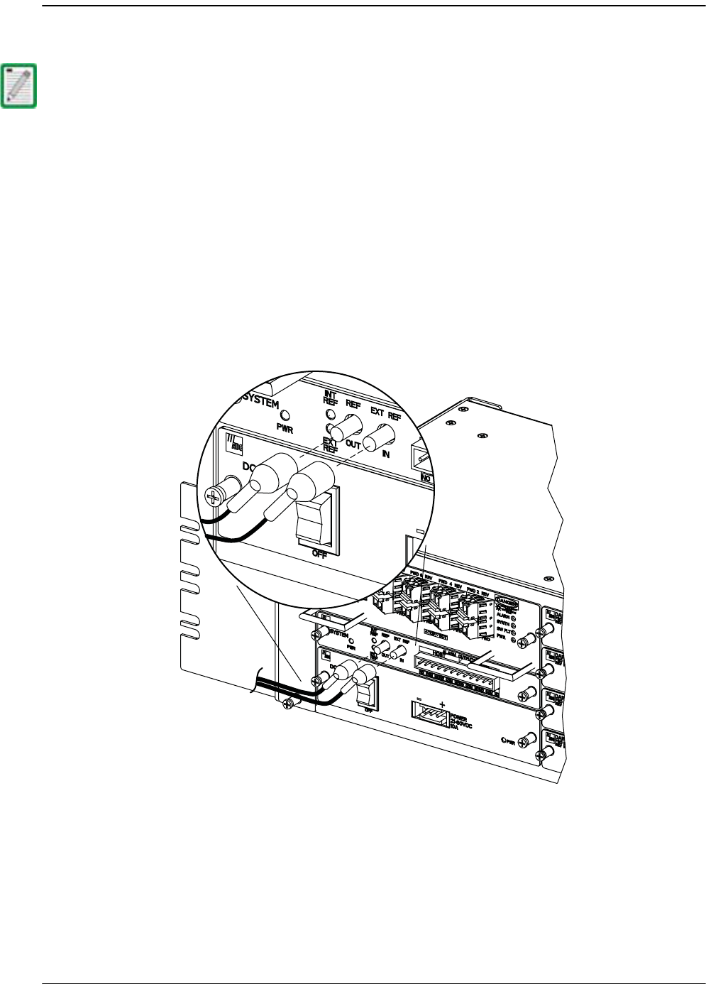
Installing the Host Unit
Page 78 FlexWave Prism Host, Remote and EMS 5.1 System Reference
© 2009 ADC Telecommunications, Inc ADCP-77-073 • Issue 2 • 11/2009
3.3.8 EXT REF Connections
EXT REF connections between multiple Hosts is supported through two QMA type
female connectors mounted on the System card. One of the jacks is designated as the
IN port and the other jack is designated as the OUT port. The EXT REF interface allows
Hosts to be connected together (in daisy-chain fashion) and clocked through a single
source.
Use the following procedure to connect EXT REF interface cables between multiple
Hosts:
488 Connect one end of the EXT REF interface cable (accessory) to the EXT REF OUT
port on Host #1.
When using the 10 MHz external reference clock the signal must be connected to the
Host before enabling the clock source in the software. If there isn’t a working external
clock source when you configure external timing, the optical sync at the Remote will be
lost and all traffic will stop flowing.
77073-066

Install the Host
FlexWave Prism Host, Remote and EMS 5.1 System Reference Page 79
ADCP-77-073 • Issue 2 • 11/2009 © 2009 ADC Telecommunications, Inc.
499 Connect the interface cables to the other Hosts that are to be daisy-chained to
Host 1. A diagram of typical EXT REF interface connections is shown below. At the
stopping point where no further Hosts are to be connected, the OUT would be left
unconnected:
aa Connect the interface cable from the EXT REF OUT port on Host 1 to the IN
port on Host 2.
bb Connect the interface cable from the EXT REF OUT port on Host 2 to the IN port
on Host 3.
500 Repeat Step 49 for each additional Host that is added to the network.
Host Unit 3 Host Unit 2 Host Unit 1
OUT EXT IN NET IN NET OUT NET IN NET OUT
77073-034
Coaxial
Interface Cables
To Next Host Unit
(Note: No EXT OUT
connection at last Host)
OUT EXT IN OUT EXT IN
REF Clock
Input
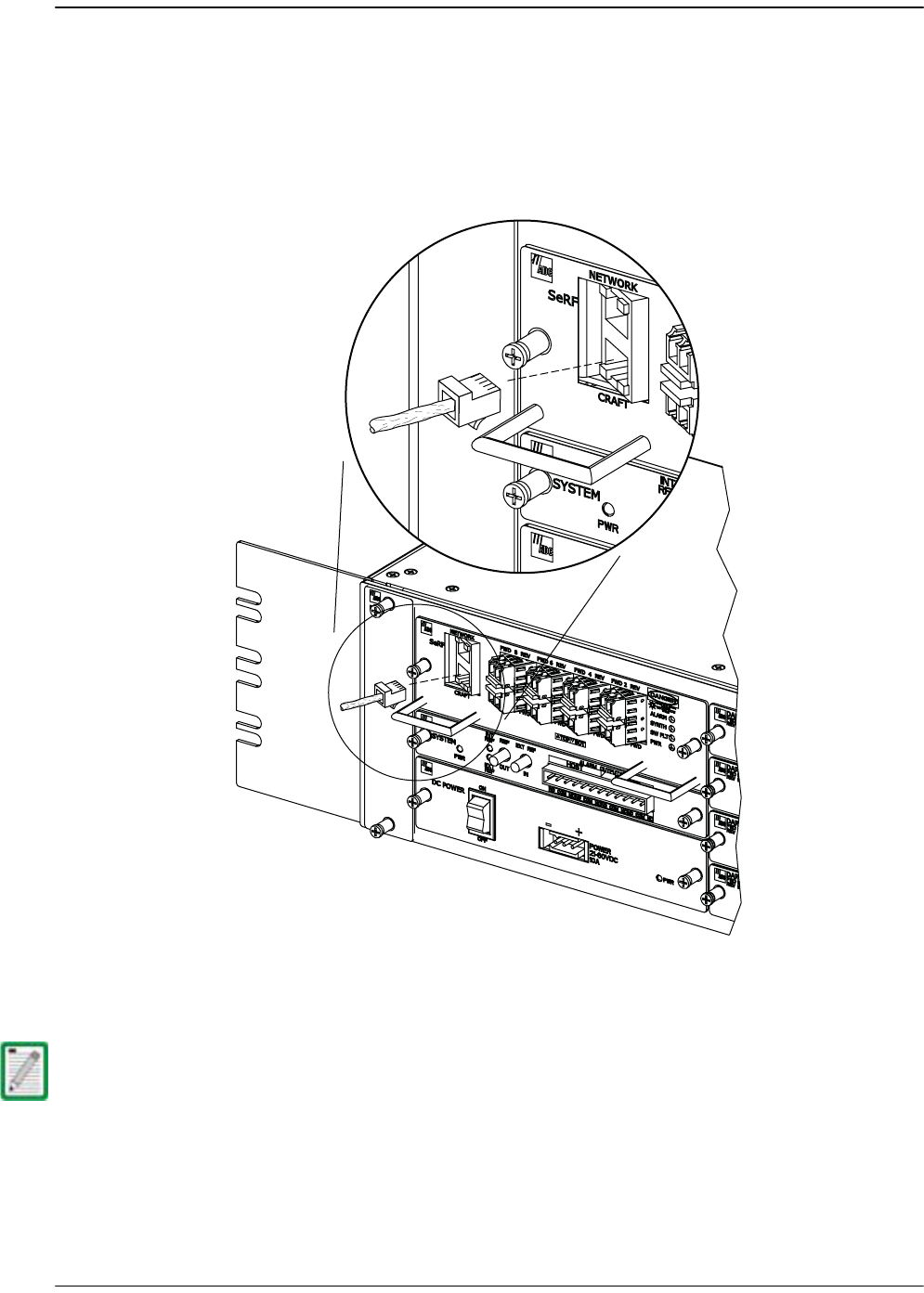
Installing the Host Unit
Page 80 FlexWave Prism Host, Remote and EMS 5.1 System Reference
© 2009 ADC Telecommunications, Inc ADCP-77-073 • Issue 2 • 11/2009
3.3.9 Computer Connection (Craft)
The SeRF front panel provides a Craft port that provides an Ethernet interface that
allows you to connect a computer to access the EMS.
511 Connect one end of an Ethernet cable (CAT5 or better, not provided by ADC) to
the Host Craft port as shown below.
522 Connect the free end of the cable to the computer’s port. Refer to the user manual
provided with the computer to locate and configure the specified port.
In the default configuration, the Craft port has a DHCP server that assigns an IP address
to the computer that is connected. You should therefore have your network interface
configured for DHCP, or configured with a static IP address in the same subnet, where
the default is 192.168.0.1/24.
77073-067
RJ-45
Connector
detail

Install the Host
FlexWave Prism Host, Remote and EMS 5.1 System Reference Page 81
ADCP-77-073 • Issue 2 • 11/2009 © 2009 ADC Telecommunications, Inc.
3.3.10 System Alarm Connections
The alarm interface between the Host and an alarm system is supported by
twelve-terminal plug (with screw-type terminals) that connects to a receptacle
mounted on the Host System card front panel. The terminal plug provides
connections to normally open (NO) and normally closed (NC) dry type alarm contacts
for both major and minor alarms. A category 3 or 5 cable is typically used to connect
the Host System card to the alarm system.
Table 3-1. System Card Alarm Pin Designations
PI
NDescription
Required
Wires
NC NO
1 Host Minor Normally Closed X
2 Host Minor Common X X
3 Host Minor Normally Open X
4 Host Major Normally Closed X
5 Host Major Common X X
6 Host Major Normally Open X
7 Remote Minor Normally
Closed
X
8 Remote Minor Common X X
9 Remote Minor Normally
Open
X
10 Remote Major Normally
Closed
X
11 Remote Major Common X X
12 Remote Major Normally Open X
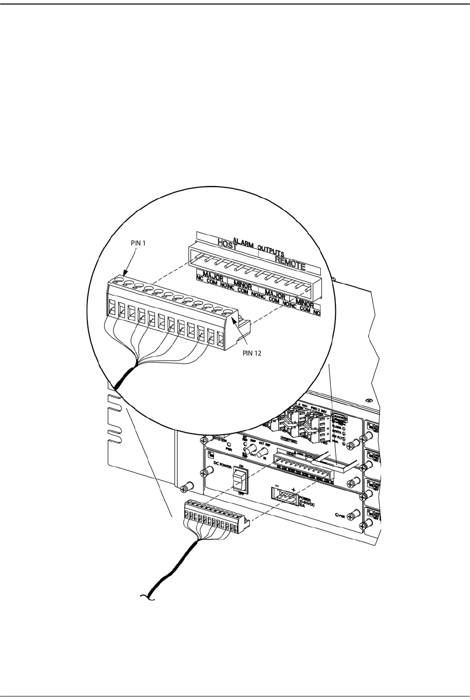
Installing the Host Unit
Page 82 FlexWave Prism Host, Remote and EMS 5.1 System Reference
© 2009 ADC Telecommunications, Inc ADCP-77-073 • Issue 2 • 11/2009
Use the following procedure to install the alarm wiring and connect it to the Host:
533 Obtain the required length of category 3 or 5 cable.
544 Route the cable between the Host System card and the alarm system (if not
already routed) and then cut to the required length. Allow sufficient slack for
dressing and organizing the cable at the Host.
555 Strip back the outer cable sheath and insulation to expose the wires at both ends
of the cable and strip back 0.2 inches (5 mm) of insulation from each wire.
566 Connect the Major alarm wire pair to the MAJOR COM/NC or MAJOR COM/NO
terminals (whichever is required by the alarm system) on the Host System card
alarm terminal connector (supplied with Host System card).
77073-068
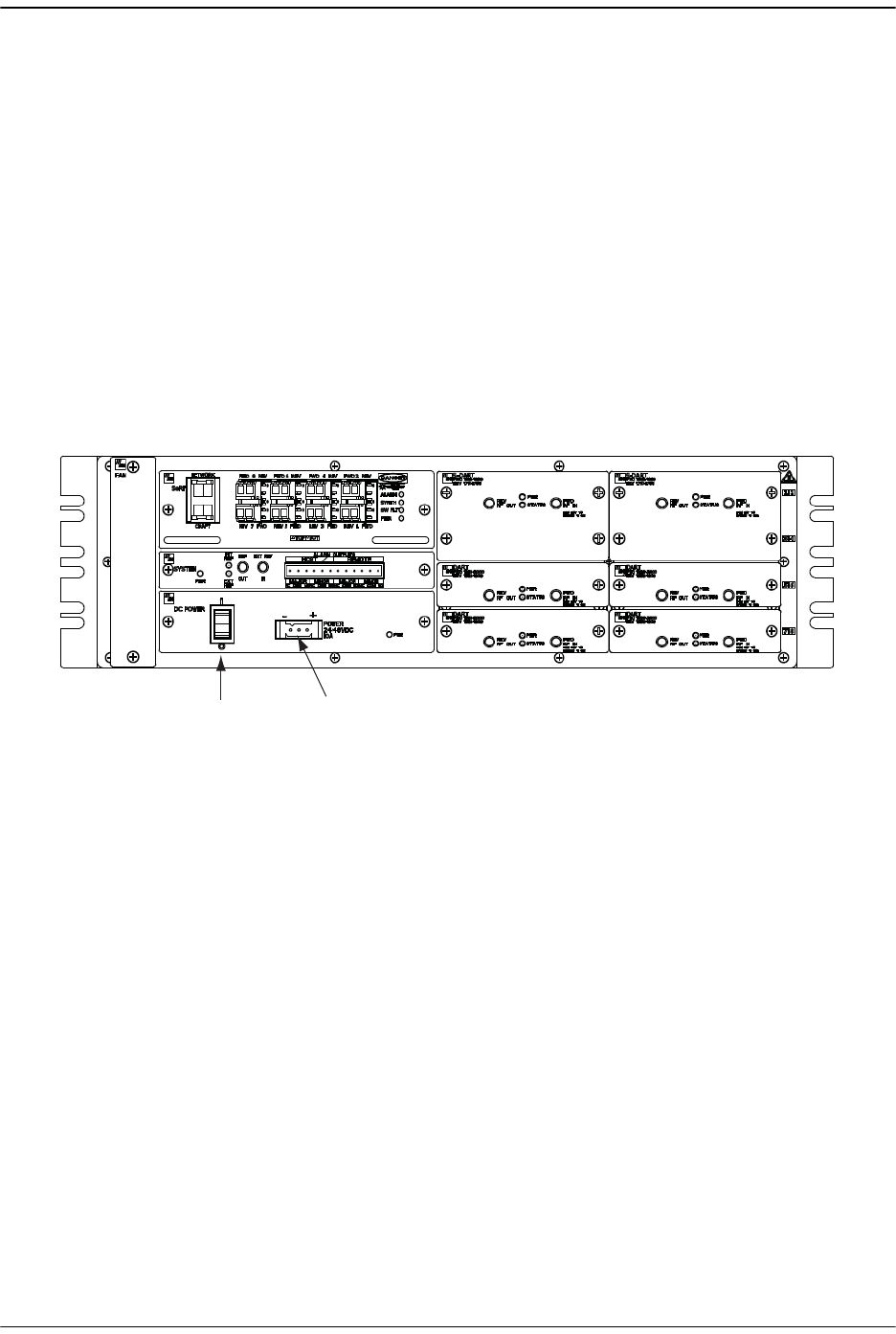
Install the Host
FlexWave Prism Host, Remote and EMS 5.1 System Reference Page 83
ADCP-77-073 • Issue 2 • 11/2009 © 2009 ADC Telecommunications, Inc.
577 Connect the Minor alarm wire pair to the MINOR COM/NC or MINOR COM/NO
terminals (whichever is required by the alarm system) on the Host System card
alarm terminal connector (as shown above and in Table 3-1).
588 Connect the Major and Minor alarm wire pairs to the appropriate terminals on the
external alarm system.
599 Dress and secure cable per standard industry practice.
3.3.11 Power Connections
The Host has a modular DC to DC power supply located on the lower left side of the
chassis, which is secured by turning its screws clock-wise until tight.
An On/Off switch is provided on the Host power supply module front panel
(Figure 3-3).
Figure 3-3. Host Power Connector
The Host is powered by ± 20 to ± 60 Vdc power (nominal ± 24 or ± 48 Vdc), which is
fed to the Host through a connector located on the front of the module. Power to the
Host must be supplied through a fuse panel (available separately). Each Host must be
protected with a fuse.
A three position terminal block is provided for connecting the power wires. The
power is fed to the Host Power Supply module through the Power Connector located
on the Host front panel (Figure 3-3). Power to the Host must be supplied through a
fuse panel such as the 20 position PowerWorx GMT Fuse Panel (available separately)
and the power must be protected with an appropriate GMT fuse:
•• 5 Amp GMT fuse for 48Vdc
•• 10 Amp GMT fuse for 24 Vdc
Power
Connector
DC Power
Switch
77073-069

Installing the Host Unit
Page 84 FlexWave Prism Host, Remote and EMS 5.1 System Reference
© 2009 ADC Telecommunications, Inc ADCP-77-073 • Issue 2 • 11/2009
Table 3-2 provides a Host power consumption matrix that you should use to calculate
power consumption for your system.
* Add 1W for each SFP added
For example, the power consumption of a fully-loaded Host, with four Dual
SuperDARTs, a SeRF card (that comprises eight SFPs), and a System card would be:
•• Nominal—131W
•• Maximum—148.4W
•• 15% Headroom—171W
Use the following procedure to install the power wiring:
600 Obtain the items listed below:
•• Wire stripper and screwdriver
•• Wire, #18 AWG (1.00 mm) red and black insulated copper wire. Recommended
wire size for the power leads, when fused in the same bay.
611 Turn power switch on power supply OFF.
622 Connect the wires to the designated terminals on the fuse panel.
633 Dress and secure the wires to the rack following local practice. Route wiring away
from sharp edges and secure in place to prevent chaffing and provide strain relief.
644 Route the wires to the terminal block on the Host Power Supply and cut them to
length, allowing sufficient length for termination.
Table 3-2. Host Power Consumption
PCB
Classic or
Single
SuperDART
Dual
SuperDART
System Card
(including Fans)
SeRF
(1 SFP)
SeRF
(8 SFPs)*
Power Consumption
Nominal 18.7W 23W 12W 23W 30W
Maximu
m
20W 26W 12.4W 25W 32W
All DC input wiring should be routed away from any sharp edges and properly secured
in place to prevent chafing and to provide strain relief. This may be achieved by
tie- wrapping wires to the rack frame or by a similar means.
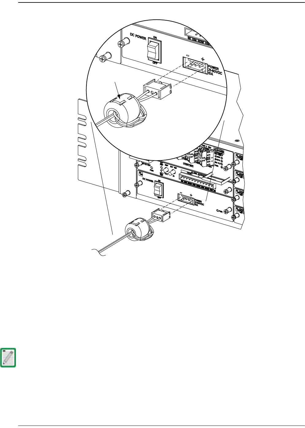
Install the Host
FlexWave Prism Host, Remote and EMS 5.1 System Reference Page 85
ADCP-77-073 • Issue 2 • 11/2009 © 2009 ADC Telecommunications, Inc.
655 Loop both power wires around and through the Ferrite as shown above. (The
Ferrite is required for FCC radiated-emissions compliance.)
666 Strip 0.5 inch (1.27 cm) of insulation from the end of each wire.
677 Insert one end of each wire into the terminal block, one into the positive (+) and
the other into the negative (–) position.
688 Insert the terminal block into the 3-pin receptacle on the front of the Host Power
Supply.
699 Install fuses in the fuse panel. Update office records as required.
When connecting the equipment to the supply circuit, check equipment nameplate
ratings to avoid overloading circuits which may cause damage to over- current
protection devices and supply wiring.
77073-070
Ferrite
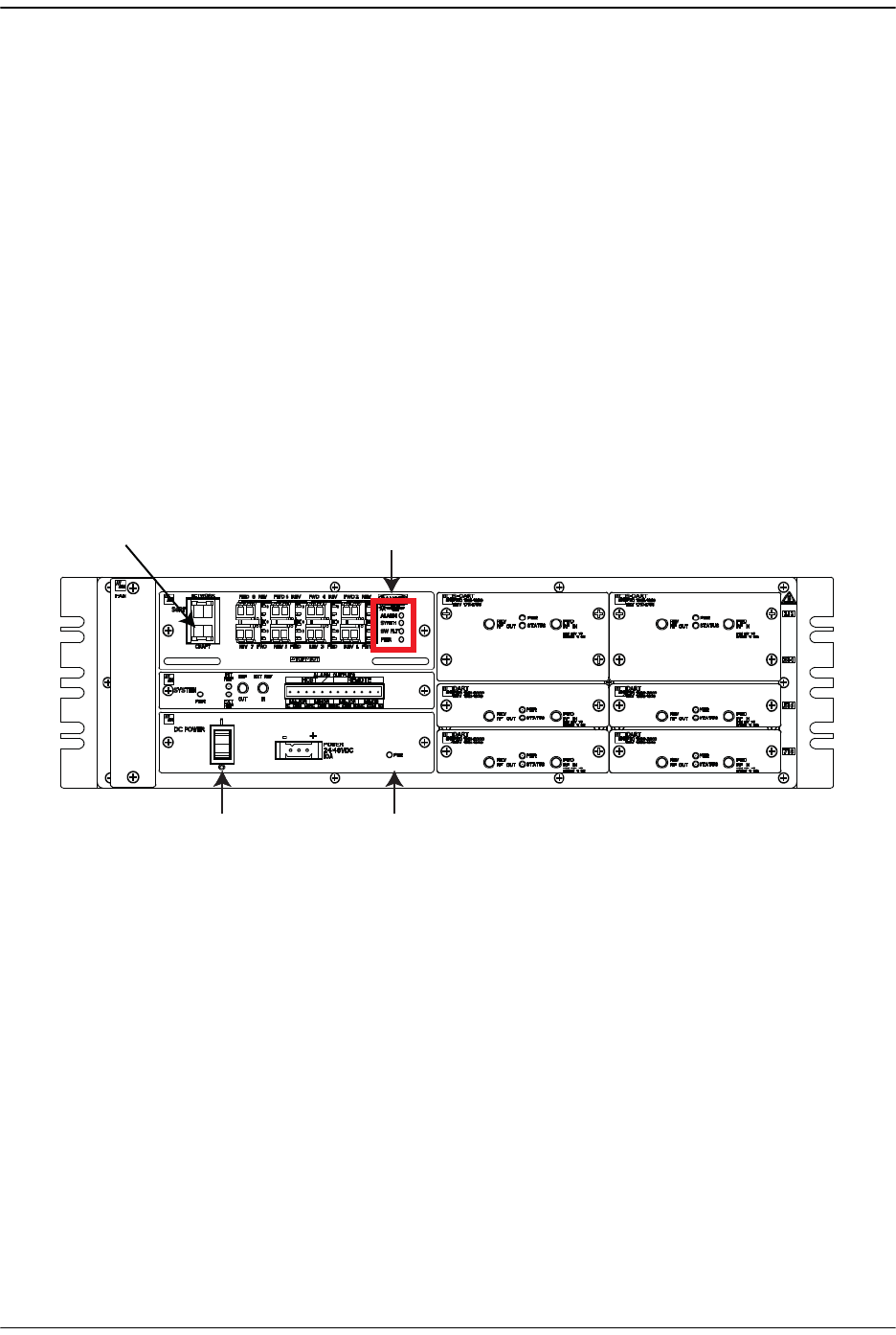
Installing the Host Unit
Page 86 FlexWave Prism Host, Remote and EMS 5.1 System Reference
© 2009 ADC Telecommunications, Inc ADCP-77-073 • Issue 2 • 11/2009
700 Turn the DC power switch to its ON position.
Under normal operating conditions, the Host responds as follows:
aa Immediately—PWR LED turns Green
bb Within 6 to 7 seconds—ALARM, SYNTH, and SW FLT LEDs turn Red
cc Approximately 10 seconds—ALARM LED goes out
dd Approximately 30 seconds—SYNTH LED goes out
ee Approximately 1 minute—SW FLT LED goes out
ff Approximately 2.5 minutes—Craft port assigns IP Address to Laptop,
making Telnet management through the Craft port available
gg Approximately 3 minutes—SYNTH LED turns Green
hh Approximately 5 minutes—Element Management System (EMS) available on
Craft port (1 - 2 minutes after SYNTH LED turns Green)
Refer to the following graphic for location of the LEDs referenced above.
ALARM LED
SYNTH LED
SW FLT LED
DC power switch Power LED
77073-074
Craft port
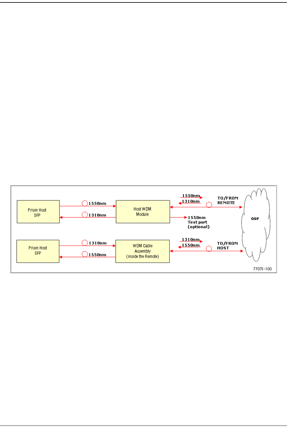
Installing the WDM Host Module Mounting Shelf and WDM Host Module
FlexWave Prism Host, Remote and EMS 5.1 System Reference Page 87
ADCP-77-073 • Issue 2 • 11/2009 © 2009 ADC Telecommunications, Inc.
3.4 INSTALLING THE WDM HOST MODULE MOUNTING
SHELF AND WDM HOST MODULE
A bi-directional wavelength division multiplexer (WDM) system is available as an
accessory item for the Prism system.
If the Prism configuration does not require the use of a WDM system, skip this
section and proceed to “Install Host in Equipment Rack” on page 66.
3.4.1 Wavelength Division Multiplexer System Overview
The Wavelength Division Multiplexer (WDM) system is an accessory product that is
used when it is desirable or necessary to combine the forward and reverse path
optical signals from one Prism system onto a single optical fiber. Each WDM system
consists of a Host and a Remote. At the Host there is a WDM chassis that contains the
WDM modules, and there is a WDM cable assembly within the Remote. Both the Host
WDM module and the Remote WDM cable assembly consist of a bi-directional
wavelength division multiplexer, as shown in Figure 3-4. Note that the WDM enables
up to three Prism RF bands to operate on a single OSP fiber.
Figure 3-4. WDM System
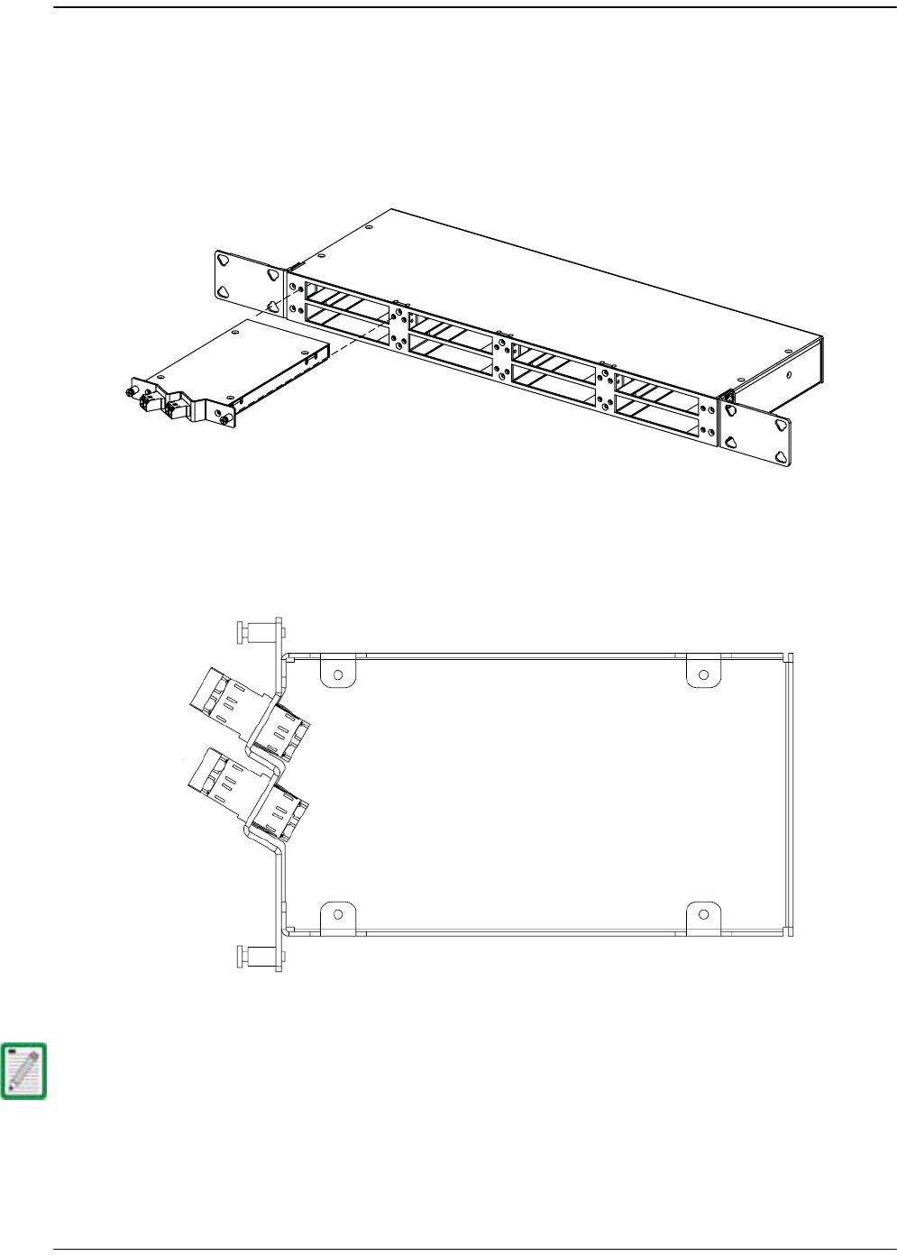
Installing the Host Unit
Page 88 FlexWave Prism Host, Remote and EMS 5.1 System Reference
© 2009 ADC Telecommunications, Inc ADCP-77-073 • Issue 2 • 11/2009
The Host WDM module is mounted within a powder-paint coated sheet metal
enclosure. A straight LC-type optical connector port is provided for connecting the
forward/reverse path optical fiber to the WDM module. A pair of fiber patch cord
leads with LC-type connectors are provided for connecting the WDM module to the
forward and reverse path optical ports on the Host SeRF card. The WDM Host module
mounting shelf and Host module are shown in Figure 3-5.
Figure 3-5. WDM Host Module and Host Module Mounting Shelf
Figure 3-6 provides WDM port information.
Figure 3-6. WDM Ports
The WDM Test port (Port 3 shown in Figure 3-6) is a monitor or trap port. When taking
a reading at this port, the signal power is 23 dB less than the input power going into
Port 1. The wavelength of light measured is 1550 nm.
22390-A
Port 1: 1550nm IN (FWD)
Port 2: 1310nm OUT (REV)
Ports
1
2
3
4
77073-029
Port 3: -23dB 1550nm Test port
Port 4: 1310/1550nm
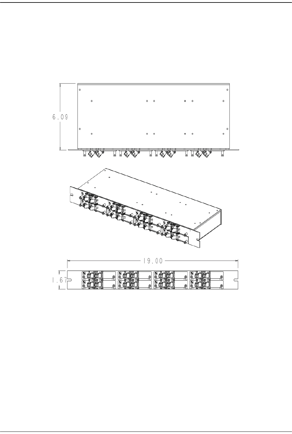
Installing the WDM Host Module Mounting Shelf and WDM Host Module
FlexWave Prism Host, Remote and EMS 5.1 System Reference Page 89
ADCP-77-073 • Issue 2 • 11/2009 © 2009 ADC Telecommunications, Inc.
Each WDM module supports a single Small Form-Factor Pluggable (SFP) port on the
Host, but a WDM chassis can support up to 8 WDM modules, which allows it to be
shared among multiple Hosts depending on the SFP port counts and system
configuration. That is, the 8 modules allows a fully loaded Host with 8 SFP modules
or multiple partially-loaded Hosts (for a maximum of 8 total SFPs). The WDM Host
module mounting shelf installs in the equipment rack with the Host. Figure 3-7 shows
a one Host WDM system.
Figure 3-7. One Host WDM System
77073-061
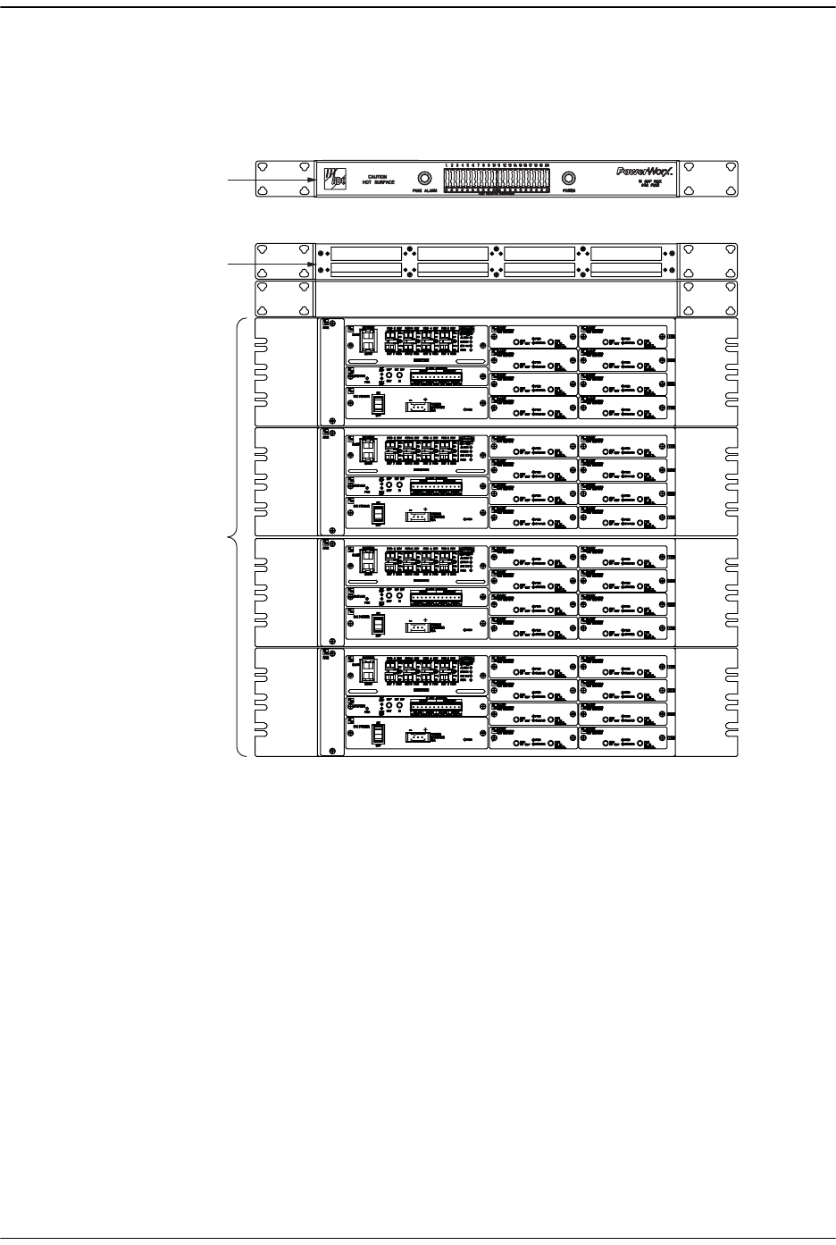
Installing the Host Unit
Page 90 FlexWave Prism Host, Remote and EMS 5.1 System Reference
© 2009 ADC Telecommunications, Inc ADCP-77-073 • Issue 2 • 11/2009
When multiple Hosts require connection to a WDM system, the Host module
mounting shelf and the Hosts should be mounted in the equipment rack as shown in
Figure 3-8. This configuration allows the fiber patch cord leads from the two Host
modules to be connected directly to the optical ports on any one of the four Hosts.
Figure 3-8. Typical WDM and Host Configuration
3.4.2 Install WDM Host Components
The WDM Host module mounting shelf may be mounted in either a 19-inch or 23-inch
EIA or WECO equipment rack. Four #12-24 screws are provided for securing the
mounting shelf to the rack.
Use the following procedure to install the WDM Host module mounting shelf in the
equipment rack and to mount the WDM modules in the WDM Host module mounting
shelf.
WDM MOUNTING
SHELF
(WITHOUT MODULES)
22392-A
POWERWORX
FUSE PANEL
HOST UNITS
HOST SLACK FIBER STORAGE
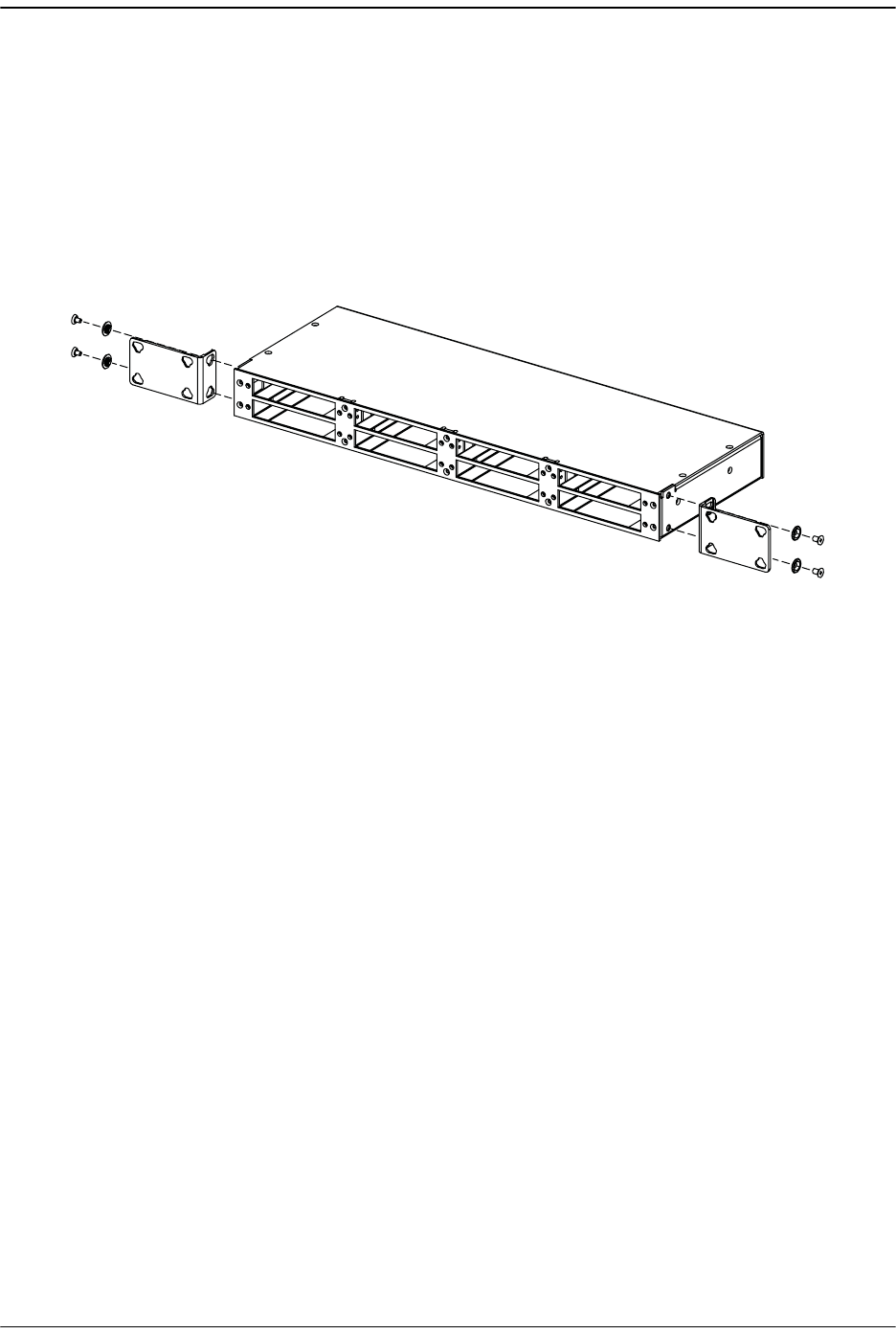
Installing the WDM Host Module Mounting Shelf and WDM Host Module
FlexWave Prism Host, Remote and EMS 5.1 System Reference Page 91
ADCP-77-073 • Issue 2 • 11/2009 © 2009 ADC Telecommunications, Inc.
11 The WDM Host module mounting shelf is shipped with the mounting brackets
installed for 23-inch rack installations. If installing the mounting shelf in a 23-inch
rack, proceed to Step 4. If installing the mounting shelf in a 19-inch rack proceed
to Step 2.
22 Remove both mounting brackets from the mounting shelf (requires Phillips
screwdriver) and save screws for reuse.
33 Reinstall both mounting brackets so the short side of the bracket is flush with the
front panel as shown below. Use the screws removed in Step 2 to attach the new
brackets to the mounting shelf.
44 Position the mounting shelf in the designated mounting space in the rack (per
system design plan) and then secure the mounting brackets to the rack using the
four #12-24 machine screws provided.
55 Install each WDM Host module in the mounting shelf. A rail on the side of the
module fits into a guide within the mounting.
66 Secure each Host module to the mounting shelf by twisting the handle on each
quarter-turn fastener 90º.
77 Carefully store the fiber patch cord leads from each Host module. At the Remote
end, the ProAx fiber used in WDM deployments is Fiber Number 1. The routing
and connection procedures for the fiber patch cords are provided in “Optical
Connections For Systems With a WDM” on page 76. Or, after connecting the fiber
patch cord, correctly store the slack cable.
22393-A

Installing the Host Unit
Page 92 FlexWave Prism Host, Remote and EMS 5.1 System Reference
© 2009 ADC Telecommunications, Inc ADCP-77-073 • Issue 2 • 11/2009
Intentionally Blank Page